Embed Size (px)
Citation preview

ePED® – electrically controlled escape door systems with Hi-O Technology
Escape route technology with intelligent door management

Escape door systemsePED technology
2
About us.
Whatever you want to secure,protect, maintain – we have technology you require.

3 Escape door systemsePED technology
Breaking new grounds, implementing new technologies, developing new ideas.Founded in 1936, the company effeff based in Albstadt became the market leaderin the field of door control systems by following a consistent strategy.After starting the electric strike production in 1947, a comprehensive productrange has been gradually developed, which enables effeff to offer suitable solutionsfor every door.
February 1st, 2000, effeff joined the ASSA ALBOY Group based in Stockholm,Sweden and merged at the beginning of 2005 with IKON GmbH Präzisionstechnik,Berlin who also belong to the group to become ASSA ABLOY SicherheitstechnikGmbH.
IKON and effeff, both renowned and well-established brands within the marketremain under ASSA ABLOY Sicherheitstechnik GmbH as do the production sites ofBerlin and Albstadt and a sales office in Ratingen.
ASSA ABLOY is the leading manufacturer and supplier of mechanical and electro-mechanical locks and related products worldwide. Our customers benefit from theextensive know-how of the largest international group of companies, meeting every requirement in terms of total security and comfort throughout the world.
Elbphilharmonie Hamburg
Bauhaus Dessau
HafenCity University Hamburg
Library Stuttgart

Escape door systemsePED technology
4
Hotline Technical advice
+49 7431 123-381
The experts at ASSA ABLOY Sicherheitstechnik would be pleased to advise youwhich electric strike model is most suitable for which installation position.
Technical adviceIn the matter of technical advice, with us you will be supported by professionals who will continue to help you on every question on technical details. Of course you can also be put into contact with specialists for questions of detail in the matter of technical risk assessment or key accounts.
Sales advice/order processingWith our commercial customer services you can deal with all questions to do withyour purchase order, for example the status of the order processing, the deliverydate, purchase order changes, but also returns or guarantee issues. Use this simpleand quick option to get information or help from our specialists. We will do thatwith pleasure.
Trade fairsYou will find effeff at many national and international trade fairs. You can obtain theexact dates from our website www.assaabloy.de
Hotline Sales/order processing
+49 7431 123-700
We assist you with words and deeds
Our product catalogue online at www.assaabloyopeningsolutions.de
Fast and up-to-datecomprehensive productinformation at any time
1 Clearly arranged layoutaccording to our different product areas...
2 the submenu will helpyou navigate through our database...
3 to find the model youneed.
4 By just clicking on thearticle, you can generatea detailed specificationsheet.
1 2
3
4

5 Escape door systemsePED technology Contents
Where can I find what I need?
About us 2 – 3Service, support and internet 4Contents 5
ePED SystemePED and Hi-O Technology 6 – 9AP0001 Escape door locking device with authorised access using key 10 – 11AP0003 Escape door locking device for doors with direction of escape from both sides 12 – 13AP0002 Application with time delay, escape door locking with time delay t1 authorised access via key 14 – 15AP0004 Application with time delay and central excape route control, escape door locking with timedelay t2 and authorised access via key 16 – 17System overview 18 – 19
ePED escape door terminalsePED® Escape door terminals in switch design 20 – 27ePED® Escape door terminals in switch design for access control sysstem 28 – 35ePED® Escape door terminals in switch design – Individual modules and accessories 36 – 48
ePED Escape door lockingIntroduction 49Escape door strike model 332.80, 332.208, 331U80F and striking plates 50 – 57 Mating coomponents 58Mounting accessories for escape door strike 59 – 60Holding magnets and accessories 61 – 66Door closer model DC700G-FT for hinge and non hinge side 67 – 76
ePED Emergency exit locksIntroduction 77Mechanical panic security lock 309N 78 – 79Mechanical panic security mutli-point lock 319N 80 – 82Motorized panic security lock 509N 83 – 84Motorized panic security multi-point lock 519N 85 – 87Handle-conrolled panic security lock 809N 88 – 89Handle-controlled panic security multi-point lock 819N 90 – 92Panic push bars type A, panic touch bars type B 93 – 94Accessories 95 – 98
ePED KonfigurationService Interface USB 99ePED IO interface and connector 100 – 102 CAN-Connector uP 103Central Control Unit (CMC) 104 – 105

Escape door systemsePED technology
6
ePED
The
Sys
tem
In the event of emergency or panic, everyone is going to be in a major hurry – and it’s situations like this that put the escape route management system to the test. Everything has to work fla-wlessly, and all components must interact with one another smoothly. effeff’s new development ePED now enables all users to combine the electrically controlled emergency exit technology with the complex door system and its control technology via intelligent bus-based Hi-O Tech-nology. ePED stands for electrically controlled Panic Exit Device. A real highlight is the ePED panic touch bar – a combination of locking
mechanism and innovative operating concept which informs and guides the user based on the situation with its simple menu and intuitive dis-play. Further advantages of ePED include delayed opening of the emergency exits as protection and useful functions such as fire protection tech-nology and access control. Reliable release when the emergency switch is thrown in the event of a malfunction as well as information on main-tenance, opening cycles and fault diagnostics are also of great benefit to the user.
Optimize security, integrate emergency exits:with ePED and Hi-O Technology
Top functionality for many applications: Nursery schools, public institutions and event venues, demen-tia wards in nursing homes, clinics, public offices, production facilities, retail stores, shopping malls and more.
Reliability, security, versatile functions and compliance with standards such as EN 13637 as a self-con-tained complete solution – ePED makes it possible!

7 Escape door systemsePED technology
ePED
The
Sys
tem
Competence which puts hazard management at ease:ePED is technology, bus control and function all in one
Operating elements: ∙ ePED door terminal with key, ePED display door terminal and ePED panic touch bar
∙ Each with operation via touch display and situa-tion-based information to guide the user
∙ A wide range of safety functions are available via bus for all versions.
∙ Modular planning, easy installation with only 4 wires and a guarantee that all system com-ponents are legally compliant complete the system’s great number of advantages.
Locking elements: ∙ The escape route locking system is activated via ePED interface with latest Hi-O Technology
∙ All-round integration into the hazard manage-ment system
∙ Worth noting: the option of connecting up to 8 ePED interfaces per door
∙ The elements are as follows: Compact surface holding magnet 827 HA + magnetic contact, Surface holding magnet 828 + magnetic con-tact, escape door strikes 331 and 332.
ePED Door terminal
ePED Display door terminal
ePED Panic touch bar
Features at a glance
Based on individual requirements, ePED offers the product selection between 3 escape door operating elements for electro-nically controlling the escape door systems.
Product ePED panic touch bars ePED display door terminal ePED door terminal
Panic door lock Yes No No
Suitable for panic doors Yes Yes Yes
Suitable for emergency exits Yes Yes Yes
Operation Touch display Touch display Key
Authorisation PIN code PIN code/RFID Key
Various authorisations
Yes Yes No
Situation-based user guidance information
Yes Yes No
Escape route sign Integrated in touch display Integrated in touch display Separate
Down counter for time delay
Integrated in touch display Integrated in touch display Optional module
Configuration Integrated touch display Integrated touch display Configuration display
Hi-O Technology Yes Yes Yes
Safety functions via bus Yes Yes Yes
Easy installation with only 4 wires
Yes Yes Yes
Networking Gateway/Ethernet Gateway/Ethernet Gateway/Ethernet
Modular planning Yes Yes Yes
Basic design ePED panic touch bar ePED display door terminalePED locking system
ePED door terminalePED locking system
8 Escape door systemsePED technology Our strength lies in our specialist knowledge
Escape Route Technology from effeff
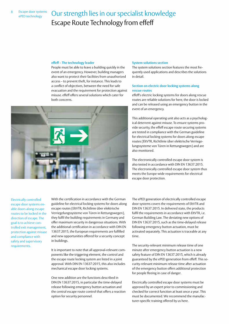
effeff – The technology leaderPeople must be able to leave a building quickly in the event of an emergency. However, building managers also want to protect their facilities from unauthorized access – to prevent theft, for instance. This leads to a conflict of objectives, between the need for safe evacuation and the requirement for protection against misuse. effeff offers several solutions which cater for both concerns.
System solutions section The system solutions section features the most fre-quently used applications and describes the solutions in detail.
Section on electric door locking systems along rescue routeseffeff's electric locking systems for doors along rescue routes are reliable solutions for here, the door is locked and can be released using an emergency button in the event of an emergency.
This additional operating unit also acts as a psycholog-ical deterrent against misuse. To ensure systems pro-vide security, the effeff escape route securing systems are tested in compliance with the German guideline for electrical locking systems for doors along escape routes (EltVTR, Richtlinie über elektrische Verriege-lungssysteme von Türen in Rettungswegen) and are also monitored.
The electronically controlled escape door system is also tested in accordance with DIN EN 13637:2015. The electronically controlled escape door system thus meets the Europe-wide requirements for electrical escape door protection.
With the certification in accordance with the German guideline for electrical locking systems for doors along escape routes (EltVTR, Richtlinie über elektrische Verriegelungssysteme von Türen in Rettungswegen), they fulfil the building requirements in Germany and offer maximum security in dangerous situations. With the additional certification in accordance with DIN EN 13637:2015, the European requirements are fulfilled and new opportunities offered for a security concept in buildings.
It is important to note that all approval-relevant com-ponents like the triggering element, the control and the escape route locking system are listed in a joint approval. With DIN EN 13637:2015, this also includes mechanical escape door locking systems.
One new addition are the functions described in DIN EN 13637:2015, in particular the time-delayed release following emergency button actuation and the central escape route control that offers a reaction option for security personnel.
The ePED generation of electrically controlled escape door systems covers the requirements of EltVTR and DIN EN 13637:2015. In delivered state, the products fulfil the requirements in accordance with EltVTR, i.e. German Building Law. The deviating new options of DIN EN 13637:2015, such as the time-delayed release following emergency button actuation, must be activated separately. This actuation is traceable at any time.
The security-relevant minimum release time of one minute after emergency button actuation is a new safety feature of DIN EN 13637:2015, which is already guaranteed by the ePED generation from effeff. This se-curity-relevant minimum release time after actuation of the emergency button offers additional protection for people fleeing in case of danger.
Electrically controlled escape door systems must be approved by an expert prior to commissioning and checked for correct function at least once a year. This must be documented. We recommend the manufac-turer-specific training offered by us here.
Electrically controlled escape door systems en-able doors along escape routes to be locked in the direction of escape. The goal is to achieve con-trolled exit management, protection against misuse and compliance with safety and supervisory requirements.

9 Escape door systemsePED technology ePED technology
Escape Route Technology from effeff
The Hi-O bus enables a simple 4-wire wiring of the Hi-O components around the door. For complex requirements in particular, this modular concept makes planning and installation easier compared with conventional solutions. The bus installation also includes the safety-relevant functions of the emer-gency button and therefore removes the need for any
additional wiring. The electrical safety functions are tested in accordance with DIN EN 61508 for functional safety of safety-related electrical/electronic/program-mable electronic systems according to class SIL 2. This certifies the fail-safe functionality for the bus solution and the delayed release when the emergency button is actuated.
24 V DC
The Hi-O door wiring offers easier installation with conventional installation cables with a limited bus wiring with a maximum total length of 50 m and stub cable length of 10 m. Special cable are required for longer cable lengths. This is described in detail in the manual D01021 ePED® Hi-O Technology™ bus.
Bus addresses are allocated automatically. A manual entry via dip switch is not necessary. A maximum of 32 bus addresses are possible in a Hi-O system. It is important to note that devices or combinations of devices need several bus addresses.
Further details are available in the ePED Hi-O Technology installation manual D01021.
Hi-O door wiring

Escape door systemsePED technology
10
ePED
The
Sys
tem
AP0001 Escape door locking device with authorised access using key
Locking device in direction of escape The door is also secured by an electric locking compo-nent (escape door strike or flat holding magnet) in the direction of escape.The door can be released at any time using the emergency button, which also triggers an audible and optical alarm. After the alarm interval has elapsed, a guidance signal is emitted to make it easier to find the exit if thick smoke is emitted, for example. The alarm is deactivated using the key switch on the door terminal.The power supply for the electrically controlled escape door system takes place via a power supply in accor-dance with DIN EN 60950-1 SELV 24 V (+/-15 %).
Escape door lock A panic lock in accordance with DIN EN 1125 or an emergency exit lock in accordance with DIN EN 179 is used depending on the application. A panic lock should preferably be used. For escape door systems in accordance with DIN EN 13637:2015, the test certifi-cate and the permissible combination described there should be observed.
Authorised access using keyAuthorised access in the direction of escape is gained using a key in the key switch integrated into the escape door control terminal. The key switch can also be used to set the door to permanent release, to re-lock and to deactivate the alarm.
The outer key switch is used to enter against the direc-tion of escape.The panic lock also needs to be unlocked.
Monitoring of the door release intervalThe time that the door is open is monitored during temporary release. A reminder signal, also known as the pre-alarm, is emitted once the permitted interval is exceeded. If this signal is ignored, the door alarm will sound and remain active until the alarm is reset. The time intervals for temporary release, pre-alarm and door alarm can be set as required. If the door is closed again before the temporary release interval comes to an end, it is then automatically re-locked or secured.
Fire alarm systemAn input is available on the ePED escape door terminal for connecting a fire alarm system. If the fire alarm system is activated, the escape door locking device is released and an alarm sounds. The alarm is auto-matically switched off and the door is locked again by resetting the fire alarm system. An alarm can be sent potential-free to other systems via the integrated relay output.
Function:
System overview:
AP001
FluchtrichtungFluchtrichtung
Gehflügel Standflügel
Panikgriffstange Panikgriffstange
Fluchttüröffnerund Fallenschloss
Fluchttüröffnerund Fallenschloss
Fluchttüröffnerund Fallenschloss
Fluchttürterminal1386-12B
Schlüsseltaster1140
1386-SIF-USB
Netz 230 V
Netzteil
Interface1386S00
Interface1386S00
Hi-OHi-O
1 x Eingang In1 KZF1 x Eingang In2 BMZ1 x Ausgang konfigurierbar
1 x input In1 temporary release1 x input In2 fire alarm system1 x output configurable
1386-SIF-USB
Key switches 1140
Escape Door Terminal1386-12B
Power 230 V
Mains adapter
Interface1386S00
Hi-O
Escape door strike and latch lock
Direction of escape
Hi-OInterface1386S00
Escape door strike and latch lock
Escape door strike and latch lock
Panic bar Panic bar
Direction of escape
Active leaf Inactive leaf

11 Escape door systemsePED technology
ePED
The
Sys
tem
Electronic access controlThe actuation via an EAC system takes place via an in-put on the ePED escape door terminal. When actuated, a temporary release is triggered. In place of a key pushbutton, the authorised operation of the escape door system can take place via an EAC system. For this, the connection of the key switch for the pulse actuation is configured by an EAC system contact and the tripping contact of the access control is contacted instead of the key switch. There are two independent inputs available, where the actuation of the internal and external side can take place separately.
OptionalFurther escape door locking elements can be connect-ed via an additional ePED interface for lockings. The ePED Hi-O IO interface for top-hat rails offers addi-tional inputs and outputs for connection with external systems and devices. The ePED Hi-O distribution aP acts as a central con-nection point for a structured Hi-O wiring. The Hi-O distributor has a supply terminal for the mains adapter of the system with max. 4A, a shear resistance for ter-minating and 8 plug-in screw terminals for connecting Hi-O cables.
EN 13637Tested device combinations in accordance with DIN EN 13637:2015 see test certificate. National require-ments, such as EltVTR in Germany, are also a prerequi-site for use.
System components Single-leaf door Double-leaf door Order code
ePED escape door terminals 24 V DC uP incl. illuminated sign as a set with ePED interface for lockings for installation
1x 1x 1386-12B2--04S0*
ePED interface for locks for installation - 1x 1386S00UP----00
Escape door strikes 1x 2x 332.80 24 VDC
Escape door strikes • • 331U80 24 VDC
Latch lock 1x 2x 807
Mains adapter 24 VDC, 1 A 1x 1x 1003-24-1----10
ePED Hi-O distribution aP • • 901-stroke-01---00
Escape door lock in accordance with DIN EN 1125 / DIN EN 179 According to the door situation and requirements. With DIN EN 13637:2015 systems, the test certificate must be observed.
Accessories Single-leaf door Double-leaf door Order code
ePED Hi-O IO interface for top-hat rail • • 901-IO-20----00
*For surfaces and versions, see variants in the product description.
• Optional
AP0001 Escape door locking device with authorised access using key

Escape door systemsePED technology
12
ePED
The
Sys
tem
AP0003 Escape door locking device for doors with direction of escape from both sides (bidirectional escape route)
Locking device in direction of escape The door is also secured by an electric locking compo-nent (escape door strike or flat holding magnet) in the direction of escape.The door can be released at any time using the emer-gency button, A door terminal is fitted to either side of the door. which also triggers an audible and optical alarm. After the alarm interval has elapsed, a guidance signal is emitted to make it easier to find the exit if thick smoke is emitted, for example. The alarm is deac-tivated using the key switch on the door terminal.Please note that the door provides no protection against burglary due to the lock's panic function on both sides and because the door can be released using the emergency button.The power supply for the electrically controlled escape door system takes place via a power supply in accor-dance with DIN EN 60950-1 SELV 24 V (+/-15 %).
Escape door lock A panic lock in accordance with DIN EN 1125 or an emergency exit lock in accor-dance with DIN EN 179 is used depending on the application. A panic lock should preferably be used. For escape door systems in accordance with DIN EN 13637:2015, the test certificate and the permissible combination described there should be observed.
Authorised access using keyAuthorised access in the direction of escape is gained using a key in the key switch integrated into the escape door control terminal. The key switch can also be used to set the door to permanent release, to re-lock and to deactivate the alarm.The outer key switch is used to enter against the direc-tion of escape.The panic lock also needs to be unlocked.
Monitoring of the door release intervalThe time that the door is open is monitored during temporary release. A reminder signal, also known as the pre-alarm, is emitted once the permitted interval is exceeded. If this signal is ignored, the door alarm will sound and remain active until the alarm is reset. The time intervals for temporary release, pre-alarm and door alarm can be set as required. If the door is closed again before the temporary release interval comes to an end, it is then automatically re-locked or secured.
Fire alarm systemAn input is available on the ePED escape door terminal for connecting a fire alarm system. If the fire alarm system is activated, the escape door locking device is released and an alarm sounds. The alarm is auto-matically switched off and the door is locked again by resetting the fire alarm system. An alarm can be sent potential-free to other systems via the integrated relay output.
Function:
System overview:
AP003
FluchtrichtungFluchtrichtung
Gehflügel Standflügel
Panikgriffstange Panikgriffstange
Fluchttüröffnerund Fallenschloss
Fluchttüröffnerund Fallenschloss
Fluchttüröffnerund Fallenschloss
Fluchttürterminal1386-12B
1386-SIF-USB
Netz 230 V
Netzteil Hi-O HubI/O-Modul901-IO-20
Interface1386S00
Interface1386S00
Hi-O
Hi-O1 x Eingang In1 KZF1 x Eingang In2 BMZ1 x Ausgang konfigurierbar
8 x Ausgang konfigurierbar9 x Eingang konfigurierbar
1 x input In1 temporary release1 x input In2 fire alarm system1 x output configurable
Hi-O
Escape door strike and latch lock
Power 230 V
Mains adapter Hi-O strokeI/O module901-IO-20
8 x output configurable9 x input configurable
Interface1386S00
1386-SIF-USB
Escape door terminal1386-12B
Direction of escape
Hi-O
Escape door strike and latch lock
Escape door strike and latch lock
Interface1386S00
Panic bar Panic bar
Active leaf Inactive leaf
Direction of escape

13 Escape door systemsePED technology
ePED
The
Sys
tem
Electronic access controlThe actuation via an EAC system takes place via an in-put on the ePED escape door terminal. When actuated, a temporary release is triggered. In place of a key pushbutton, the authorised operation of the escape door system can take place via an EAC system. For this, the connection of the key switch for the pulse actuation is configured by an EAC system contact and the tripping contact of the access control is contacted instead of the key switch. There are two independent inputs available, where the actuation of the internal and external side can take place separately.
OptionalFurther escape door locking elements can be connect-ed via an additional ePED interface for lockings. The ePED Hi-O IO interface for top-hat rails offers addi-tional inputs and outputs for connection with external systems and devices. The ePED Hi-O distribution aP acts as a central con-nection point for a structured Hi-O wiring. The Hi-O distributor has a supply terminal for the mains adapter of the system with max. 4A, a shear resistance for ter-minating and 8 plug-in screw terminals for connecting Hi-O cables.
EN 13637Tested device combinations in accordance with DIN EN 13637:2015 see test certificate. National require-ments, such as EltVTR in Germany, are also a prerequi-site for use.
System components Single-leaf door Double-leaf door Order code
ePED escape door terminals 24 V DC uP incl. illuminated sign as a set with ePED interface for lockings for installation
1x 1x 1386-12B2--04S0*
ePED escape door terminals 24 V DC uP incl. illuminated sign 1x 1x 1386-12B2--0400*
ePED interface for locks for installation - 1x 1386S00UP----00
Escape door strikes 1x 1x 332.80 24 VDC
Escape door strikes • • 331U80 24 VDC
Latch lock 1x 1x 807
Magnetic contact 1x
Mains adapter 24 VDC, 1 A 1x 1x 1003-24-1----10
ePED Hi-O distribution AP • • 901-stroke-01---00
Escape door lock in accordance with DIN EN 1125 / DIN EN 179 According to the door situation and requirements. With DIN EN 13637:2015 systems, the test certificate must be observed.
Accessories Single-leaf door Double-leaf door Order code
ePED Hi-O IO-interface for top-hat rail • • 901-IO-20----00
* For design versions, see product description.• Optional
AP0003 Escape door locking device for doors with direction of escape from both sides (bidirectional escape route)

Escape door systemsePED technology
14
ePED
The
Sys
tem
AP0002 Application with time delayEscape door locking with time delay t1 and authorised access via key
Locking device in direction of escape The door is also secured by an electric locking component (escape door strike or flat holding magnet) in the direction of escape.The door can be released at any time using the emergency button. This starts the time delay of max. 15 seconds to release and the alarm is triggered and indicated visually and acoustically. Once the time has elapsed, the electric escape door locking system is released automatically and the door can be accessed. The delayed release gives supervisory or security personnel a reaction time, thus enabling them to act accordingly. After the alarm interval has elapsed, a guidance signal is emitted to make it easier to find the exit if thick smoke is emitted, for example. The alarm is deactivated using the key switch on the door terminal.The power supply for the electrically controlled escape door system takes place via a power supply in accor-dance with DIN EN 60950-1 SELV 24 V (+/-15 %).Note: The use of a delayed release in escape routes requires approval by the responsible inspection authority.
Escape door lock A panic lock in accordance with DIN EN 1125 or an emergency exit lock in accordance with DIN EN 179 is used depending on the application. A panic lock should preferably be used. For escape door systems in accordance with DIN EN 13637:2015, the test certifi-
cate and the permissible combination described there should be observed.
Authorised access using keyAuthorised access in the direction of escape is gained using a key in the key switch integrated into the escape door control terminal. The key switch can also be used to set the door to permanent release, to re-lock and to deactivate the alarm.The outer key switch is used to enter against the direc-tion of escape.The panic lock also needs to be unlocked.
Monitoring of the door release intervalThe time that the door is open is monitored during temporary release. A reminder signal, also known as the pre-alarm, is emitted once the permitted interval is exceeded. If this signal is ignored, the door alarm will sound and remain active until the alarm is reset. The time intervals for temporary release, pre-alarm and door alarm can be set as required. If the door is closed again before the temporary release interval comes to an end, it is then automatically re-locked or secured.
Fire alarm systemAn input is available on the ePED escape door terminal for connecting a fire alarm system. If the fire alarm system is activated, the escape door locking device is released and an alarm sounds. The alarm is auto-
Function:
System overview:
AP002
FluchtrichtungFluchtrichtung
Gehflügel Standflügel
Panikgriffstange Panikgriffstange
Fluchttüröffnerund Fallenschloss
Fluchttüröffnerund Fallenschloss
Fluchttüröffnerund Fallenschloss
Fluchttürterminal1386Z12B
Schlüsseltaster1140
1386-SIF-USB
Netz 230 V
Netzteil
Interface1386S00
Interface1386S00
Hi-OHi-O
1 x Eingang In1 KZF1 x Eingang In2 BMZ1 x Ausgang konfigurierbar
1 x input In1 temporary release1 x input In2 fire alarm system1 x output configurable
Hi-O
Escape door strike and latch lock
Power 230 V
Mains adapter
Interface1386S00
1386-SIF-USB
Key switches1140
Escape door terminal1386Z12B
Direction of escape
Hi-O
Interface1386S00
Escape door strike and latch lock
Escape door strike and latch lock
Panic bar Panic bar
Active leaf Inactive leaf
Direction of escape

15 Escape door systemsePED technology
ePED
The
Sys
tem
matically switched off and the door is locked again by resetting the fire alarm system. An alarm can be sent potential-free to other systems via the integrated relay output.
Electronic access controlThe actuation via an EAC system takes place via an in-put on the ePED escape door terminal. When actuated, a temporary release is triggered. In place of a key pushbutton, the authorised operation of the escape door system can take place via an EAC system. For this, the connection of the key switch for the pulse actuation is configured by an EAC system contact and the tripping contact of the access control is contacted instead of the key switch. There are two independent inputs available, where the actuation of the internal and external side can take place separately.
OptionalFurther escape door locking elements can be connect-ed via an additional ePED interface for lockings. The ePED Hi-O IO interface for top-hat rails offers 9 additional inputs and 8 additional outputs for connec-tion with external systems and devices. The ePED Hi-O distribution aP acts as a central con-nection point for a structured Hi-O wiring. The Hi-O distributor has a supply terminal for the mains adapter of the system with max. 4A, a shear resistance for ter-minating and 8 plug-in screw terminals for connecting Hi-O cables.
EN 13637Tested device combinations in accordance with DIN EN 13637:2015 see test certificate. National require-ments, such as EltVTR in Germany, are also a prerequi-site for use.
System components Single-leaf door Double-leaf door Order code
ePED escape door terminals 24 V DC uP for time delay and illuminated sign as a set with ePED interface for lockings for installation
1x 1x 1386Z12B2--04S0
ePED interface for locks for installation 1x 1x 1386S00UP----00
Escape door strikes - 1x 332.80 24 VDC
Escape door strikes 1x 1x 331U80 24 VDC
Latch lock • • 807
Mains adapter 24 VDC, 1 A 1x 1x 1003-24-1----10
ePED Hi-O distribution AP 1x 901-stroke-01---00
Escape door lock in accordance with DIN EN 1125 / DIN EN 179 1x 1x 1003-24-1----10
ePED Hi-O distribution AP • • 901-stroke-01---00
Escape door lock in accordance with DIN EN 1125 / DIN EN 179 According to the door situation and requirements. With DIN EN 13637:2015 systems, the test certificate must be observed.
Accessories Single-leaf door Double-leaf door Order code
ePED Hi-O IO interface for top-hat rail • • 901-IO-20----00
* For design versions, see product description.• Optional
AP0002 Application with time delayEscape door locking with time delay t1 and authorised access via key

Escape door systemsePED technology
16
ePED
The
Sys
tem
AP0004 Application with time delay and central escape route controlEscape door locking with time delay t2 and authorised access via key
The central escape route control supplements the door-based electrically controlled escape door system with a central universal-door operating and control unit. This enables extended monitoring of the escape routes in the contents with the security concept of the building.
The ePED® central escape route control system 1386CMC is a central operating panel with which authorised persons monitor and operate the electri-cally-controlled escape-door system, includingthe double release delay.
The escape door system is equipped with ePED® escape route technology. The Ethernet connection is established with an ePED® CMC Connector 1386CMC-CON on every escape door (manual D01118xx ePED CMC Connector 1386CMC-CON), with the following applicable limits:a central escape route control 1386CMC can control a maximum of 128 escape doors via 128 CMC connec-tors 1386CMC-CON, andone escape door can be controlled by no more than 32 1386CMC central escape route control systems via a 1386CMC-CON CMC connector.
Note: The use of a delayed release in escape routes requires approval by the responsible inspection authority.
Emergency button for central release With the emergency button for central release, all escape doors of the building or escape door groups are released from one or several central points in an emergency or panic situation.The central points are manned by security personnel. An emergency button can be manned by anyone in the security personnel rooms.
Extended time delay t2Escape door terminals are located on the escape doors with time delay with a red emergency button. If an emergency button is actuated, the terminal for the relevant escape door reports a release request to the central escape route control.If a release request is triggered on one or multiple escape doors, the release delay is initially 15 seconds (t1). The escape doors remain locked during this time. This is reported to the central escape route control via a visual and an acoustic signal.The double release delay extends a triggered release delay from 15 to a maximum of 180 seconds (t2). The release delay can be extended from one or several central escape route controls by authorised security personnel during release delay t1. If the emergency buttons on several doors were actu-ated at the same time, the release delay is extended on all relevant escape doors. If more emergency buttons are then actuated, another notification takes place and the release delay can also be extended for these escape doors.
1386CMC 1386CMC
Function:
System overview:

17 Escape door systemsePED technology
ePED
The
Sys
tem
To assess the situation, the security personnel must be able to view all relevant escape doors directly or via video monitoring. An extension of the release delay without being able to see the escape doors is not permitted.Depending on the configuration, the initial release delay may be less than 15 seconds and the extended release time may be less than 180 seconds.
Status displayThe status of all escape doors or groups is shown on the operating panel of the central escape route con-trol. This is a summarised display of all escape doors, alarm and fault messages.
EN 13637Tested device combinations in accordance with DIN EN 13637:2015 see test certificate. National require-ments, such as EltVTR in Germany, are also a prerequi-site for use.
System components Single-leaf door Double-leaf door Order code
ePED escape door terminals 24 V DC uP for time delay and illuminated sign as a set with ePED interface for lockings for installation
1x 1x 1386Z12B2--04S0
ePED interface for locks for installation - 1x 1386S00UP----00
Escape door strikes 1x 2x 332.80 24 VDC
Escape door strikes • • 331U80 24 VDC
Latch lock 1x 2x 807
Mains adapter 24 VDC, 1 A 1x 1x 1003-24-2----10
ePED Hi-O distribution AP • • 901-stroke-01---00
Escape door lock in accordance with DIN EN 1125 / DIN EN 179 According to the door situation and requirements. With DIN EN 13637:2015 systems, the test certificate must be observed.
ePED® CMC Connector Ethernet 1x 1x 1386CMC-CON--00
Accessories Single-leaf door Double-leaf door Order code
ePED Hi-O IO interface for top-hat rail • • 901-IO-20----00
ePED® central escape route control (CMC)- in the combined wall / desktop enclosure- for control panel installation- in the 19” sub-rack
1x••
1386CMC-3-342001386CMC-1-342001386CMC-5-38400
Emergency power supply with two battery packs in the steel housing with top-hat rail 1x 1006-24030SG-00
* For design versions, see product description.• Optional
AP0004 Application with time delay and central escape route controlEscape door locking with time delay t2 and authorised access via key

Escape door systemsePED technology
18
ePED
The
Sys
tem
Applicationswithout time delay
Applicationswith time delay
ePED central escape routecontrol (CMC)
ePED CMCconnector
Hi-Odistributor
Interface forlocking devices
Controlled push bar withdisplay terminal
Controlled push bar
Push bar with emergency switch function
Hi-O IO Interface
StatusInput 1Input 2Input 3Input 4Input 5Input 6Input 7Input 8
Output 1Output 2Output 3Output 4Output 5Output 6Output 7Output 8
ePED Doorconnector
Push for emergency exit
System overview
Currently, device combinations are still being tested. Please enquire about the current status of approval.

19 Escape door systemsePED technology
ePED
The
Sys
tem
Applicationswithout time delay
Applicationswith time delay
ePED central escape routecontrol (CMC)
ePED CMCconnector
Hi-Odistributor
Interface forlocking devices
Controlled push bar withdisplay terminal
Controlled push bar
Push bar with emergency switch function
Hi-O IO Interface
StatusInput 1Input 2Input 3Input 4Input 5Input 6Input 7Input 8
Output 1Output 2Output 3Output 4Output 5Output 6Output 7Output 8
ePED Doorconnector
Push for emergency exit

Escape door systemsePED technology
20
ePED
® E
scap
e do
or te
rmin
al
ePED® Escape door terminal in switch designePED® escape door terminal 24 V DC, flush-mounted with illuminated pictogram
Technical attributes
Required power supply in accordance with DIN EN 60950-1 SELV 24 V (+/-15 %)
Outputs 1 x 30 V / 1 A switchover contact
Control function Yes, Hi-O technology
Operating and display function Yes, integrated
Power supply External power supply required
Connection 4-wire bus
Time delay No
Illuminated pictogram Yes
Down Counter No
Emergency button Yes, latching
Control element Key switch with Euro profile cylinder; cam position 8 x 45°; 30.5 mm long
Initial configuration With ePED® service inter-face and software for MS Windows
Operating temperature range -10 °C – +55 °C
Area of application For use in indoor areas
Class of protection IP30 (if fully installed)
Installation in DIN switch boxes >= 62.5 mm deep
Dimension 3 gang switch combination
Sabotage switch Yes
Inputs 2
Amount of bus addresses 2
Key switch on opposite side to direc-tion of escape
Yes (without display)
Escape door terminal with bi-directio-nal escape route
Yes
Certified in compliance with EltVTR; DIN EN 13637:2015
ePED® terminal, flush-mounted with illuminated pictogramFor use without time delay, with 4-wire bus cabling in Hi-O technology.With emergency open module for the control and monitoring of electrical locking elements for escape routes.For mounting in DIN switch boxes for light switch sys-tems with manufacturer-specific covers and frames.Consists of: ∙ illuminated pictogram; ∙ emergency open module; ∙ key switch module
Article / Feature Order no.
Jung AS500 - alpine white 1 3 8 6 - 1 2 B 1 - - 0 4 0 0
Jung AS500; green 1 3 8 6 - 1 2 B 1 - - 1 8 0 0
Jung LS 990 - alpine white 1 3 8 6 - 1 2 B 6 - - 0 4 0 0
Jung LS 990 - stainless steel 1 3 8 6 - 1 2 B 6 3 5 3 5 0 0
Gira E2 - gloss pure white 1 3 8 6 - 1 2 B 2 - - 0 4 0 0
Gira E2 – aluminium finish 1 3 8 6 - 1 2 B 2 - - 3 5 0 0
Gira Standard 55 - glossy, pure white 1 3 8 6 - 1 2 B 3 - - 0 4 0 0
Gira Stainless Steel Series 21 1 3 8 6 - 1 2 B 5 3 5 3 5 0 0

21 Escape door systemsePED technology
ePED
® E
scap
e do
or te
rmin
al
ePED® Escape door terminal in switch designePED® escape door terminal 24 V DC, flush-mounted with illuminated pictogram
Technical attributes
Required power supply in accordance with DIN EN 60950-1 SELV 24 V (+/-15 %)
Inputs 2
Outputs 1 x 30 V / 1 A switchover contact
Control function Yes, Hi-O technology
Operating and display function Yes, integrated
Power supply External power supply required
Connection 4-wire bus
Time delay No
Illuminated pictogram Yes
Down Counter No
Emergency button Yes, latching
Control element Key switch with Euro profile cylinder; cam position 8 x 45°; 30.5 mm long
Initial configuration With ePED® service inter-face and software for MS Windows
Operating temperature range -10 °C – +55 °C
Area of application For use in indoor areas
Class of protection IP30 (if fully installed)
Installation in DIN switch boxes >= 62.5 mm deep
Dimension 3 gang switch combination
Sabotage switch Yes
Amount of bus addresses 3
Key switch on opposite side to direc-tion of escape
Yes (without display)
Escape door terminal with bi-directio-nal escape route
Yes
Certified in compliance with EltVTR; DIN EN 13637:2015
ePED® terminal, flush-mounted with illuminated pictogram included 1386S00UPFor use without time delay, with 4-wire bus cabling in Hi-O technology.With emergency open module for the control and monitoring of electrical locking elements for escape routes.For mounting in DIN switch boxes for light switch sys-tems with manufacturer-specific covers and frames.Consists of: ∙ illuminated pictogram; ∙ emergency open module; ∙ key switch module
With ePED® interface for locks for installation in distri-bution boxes
Article / Feature Order no.
Jung AS500 - alpine white; incl. 1386S00UP
1 3 8 6 - 1 2 B 1 - - 0 4 S 0
Jung AS500 - green; incl. 1386S00UP 1 3 8 6 - 1 2 B 1 - - 1 8 S 0
Jung LS 990 - alpine white; incl. 1386S00UP
1 3 8 6 - 1 2 B 6 - - 0 4 S 0
Jung LS 990 - stainless steel; incl. 1386S00UP
1 3 8 6 - 1 2 B 6 3 5 3 5 S 0
Gira E2 - gloss pure white; incl. 1386S00UP
1 3 8 6 - 1 2 B 2 - - 0 4 S 0
Gira E2 – aluminum finish; incl. 1386S00UP
1 3 8 6 - 1 2 B 2 - - 3 5 S 0
Gira standard 55 - gloss pure white; incl. 1386S00UP
1 3 8 6 - 1 2 B 3 - - 0 4 S 0
Gira stainless steel Series 21; incl. 1386S00UP
1 3 8 6 - 1 2 B 5 3 5 3 5 S 0

Escape door systemsePED technology
22
ePED
® E
scap
e do
or te
rmin
al
ePED® Escape door terminal in switch designePED® escape door terminal 24 V DC, surface-mounted with illuminated pictogram
Technical attributes
Required power supply in accordance with DIN EN 60950-1 SELV 24 V (+/-15 %)
Inputs 2
Outputs 1 x 30 V / 1 A switchover contact
Control function Yes, Hi-O technology
Operating and display function Yes, integrated
Connection 4-wire bus
Time delay No
Illuminated pictogram Yes
Down Counter No
Emergency button Yes, latching
Control element Key switch with Euro profile cylinder; cam position 8 x 45°; 30.5 mm long
Initial configuration With ePED® service inter-face and software for MS Windows
Operating temperature range -10 °C – +55 °C
Area of application For use in indoor areas
Class of protection IP30 (if fully installed)
Installation Surface fitting
Dimension 3 gang housing
Sabotage switch Yes
Amount of bus addresses 2
Key switch on opposite side to direc-tion of escape
Yes (without display)
Escape door terminal with bi-directio-nal escape route
Yes
Certified in compliance with EltVTR; DIN EN 13637:2015
ePED® terminal, surface-mounted with illuminated pictogramFor use without time delay, with 4-wire bus cabling in Hi-O technology.With emergency open module for the control and monitoring of electrical locking elements for escape routes.For surface mounting with manufacturer-specific co-vers and housing.Consists of: ∙ illuminated pictogram; ∙ emergency open module; ∙ key switch module
Article / Feature Order no.
Gira profile 55 - pure white 1 3 8 6 - 1 2 B 7 - - 0 4 0 0
Gira profile 55 - aluminum finish 1 3 8 6 - 1 2 B 7 - - 3 5 0 0

23 Escape door systemsePED technology
ePED
® E
scap
e do
or te
rmin
al
ePED® Escape door terminal in switch designePED® escape door terminal 24 V DC, surface-mounted with illuminated pictogram
Technical attributes
Required power supply in accordance with DIN EN 60950-1 SELV 24 V (+/-15 %)
Inputs 2
Outputs 1 x 30 V / 1 A switchover contact
Control function Yes, Hi-O technology
Operating and display function Yes, integrated
Connection 4-wire bus
Time delay No
Illuminated pictogram Yes
Down Counter No
Emergency button Yes, latching
Control element Key switch with Euro profile cylinder; cam position 8 x 45°; 30.5 mm long
Initial configuration With ePED® service inter-face and software for MS Windows
Operating temperature range -10 °C – +55 °C
Area of application For use in indoor areas
Class of protection IP30 (if fully installed)
Installation Surface fitting
Dimension 3 gang housing
Sabotage switch Yes
Amount of bus addresses 3
Key switch on opposite side to direc-tion of escape
Yes (without display)
Escape door terminal with bi-directio-nal escape route
Yes
Certified in compliance with EltVTR; DIN EN 13637:2015
ePED® terminal, surface-mounted with illuminated pictogram, included 1386S00UPFor use without time delay, with 4-wire bus cabling in Hi-O technology.With emergency open module for the control and monitoring of electrical locking elements for escape routes.For surface mounting with manufacturer-specific co-vers and housing.Consists of: ∙ illuminated pictogram; ∙ emergency open module; ∙ key switch module
With ePED® interface for locks for installation in distri-bution boxes
Article / Feature Order no.
Gira profile 55 - pure white; incl. 1386S00UP
1 3 8 6 - 1 2 B 7 - - 0 4 S 0
Gira profile 55 - aluminum finish; incl. 1386S00UP
1 3 8 6 - 1 2 B 7 - - 3 5 S 0

Escape door systemsePED technology
24
ePED
® E
scap
e do
or te
rmin
al
ePED® Escape door terminal in switch designePED® escape door terminal 24 V DC, flush-mounted for time delay and illuminated pictogram
Technical attributes
Required power supply in accordance with DIN EN 60950-1 SELV 24 V (+/-15 %)
Inputs 2
Outputs 1 x 30 V / 1 A switchover contact
Control function Yes, Hi-O technology
Operating and display function Yes, integrated
Connection 4-wire bus
Time delay Yes
Illuminated pictogram Yes
Down Counter Yes
Emergency button Yes, latching
Control element Key switch with Euro profile cylinder; cam position 8 x 45°; 30.5 mm long
Initial configuration With ePED® service inter-face and software for MS Windows
Operating temperature range -10 °C – +55 °C
Area of application For use in indoor areas
Class of protection IP30 (if fully installed)
Installation in DIN switch boxes >= 62.5 mm deep
Dimension 4 gang switch combination
Sabotage switch Yes
Amount of bus addresses 3
Key switch on opposite side to direc-tion of escape
Yes (without display)
Escape door terminal with bi-directio-nal escape route
Yes
Certified in compliance with EltVTR; DIN EN 13637:2015
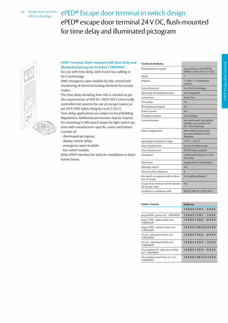
ePED® terminal, flush-mounted with time delay and illuminated pictogramFor use with time delay, with 4-wire bus cabling in Hi-O technology.With emergency open module for the control and monitoring of electrical locking elements for escape routes.The time delay deviating from this is checked as per the requirements of DIN EN 13637:2015 (electrically controlled exit systems for use on escape routes) as per EN 61508 Safety Integrity Level 2 (SIL2).Time delay applications are subject to local Building Regulations. Additional permissions may be reqired.For mounting in DIN switch boxes for light switch sys-tems with manufacturer-specific covers and frames.Consists of: ∙ illuminated pictogram; ∙ display release delay; ∙ emergency open module; ∙ key switch module
Article / Feature Order no.
Jung AS500 - alpine white 1 3 8 6 Z 1 2 B 1 - - 0 4 0 0
Jung AS500; green 1 3 8 6 Z 1 2 B 1 - - 1 8 0 0
Jung LS 990 - alpine white 1 3 8 6 Z 1 2 B 6 - - 0 4 0 0
Jung LS 990 - stainless steel 1 3 8 6 Z 1 2 B 6 3 5 3 5 0 0
Gira E2 - gloss pure white 1 3 8 6 Z 1 2 B 2 - - 0 4 0 0
Gira E2 – aluminium finish 1 3 8 6 Z 1 2 B 2 - - 3 5 0 0
Gira Standard 55 - glossy, pure white 1 3 8 6 Z 1 2 B 3 - - 0 4 0 0
Gira Stainless Steel Series 21 1 3 8 6 Z 1 2 B 5 3 5 3 5 0 0
25 Escape door systemsePED technology
ePED
® E
scap
e do
or te
rmin
al
ePED® Escape door terminal in switch designePED® escape door terminal 24 V DC, flush-mounted for time delay and illuminated pictogram
Technical attributes
Required power supply in accordance with DIN EN 60950-1 SELV 24 V (+/-15 %)
Inputs 2
Outputs 1 x 30 V / 1 A switchover contact
Control function Yes, Hi-O technology
Operating and display function Yes, integrated
Connection 4-wire bus
Time delay Yes
Illuminated pictogram Yes
Down Counter Yes
Emergency button Yes, latching
Control element Key switch with Euro profile cylinder; cam position 8 x 45°; 30.5 mm long
Initial configuration With ePED® service inter-face and software for MS Windows
Operating temperature range -10 °C – +55 °C
Area of application For use in indoor areas
Class of protection IP30 (if fully installed)
Installation in DIN switch boxes >= 62.5 mm deep
Dimension 4 gang switch combination
Sabotage switch Yes
Amount of bus addresses 4
Key switch on opposite side to direc-tion of escape
Yes (without display)
Escape door terminal with bi-directio-nal escape route
Yes
Certified in compliance with EltVTR; DIN EN 13637:2015
ePED® terminal, flush-mounted with time delay and illuminated pictogram included 1386S00UPFor use with time delay, with 4-wire bus cabling in Hi-O technology.With emergency open module for the control and monitoring of electrical locking elements for escape routes.The time delay deviating from this is checked as per the requirements of DIN EN 13637:2015 (electrically controlled exit systems for use on escape routes) as per EN 61508 Safety Integrity Level 2 (SIL2).Time delay applications are subject to local Building Regulations. Additional permissions may be reqired.For mounting in DIN switch boxes for light switch sys-tems with manufacturer-specific covers and frames.Consists of: ∙ illuminated pictogram; ∙ display release delay; ∙ emergency open module; ∙ key switch module
With ePED® interface for locks for installation in distri-bution boxes
Article / Feature Order no.
1 3 8 6 Z 1 2 B 1 - - 0 4 S 0
Jung AS500 - green; incl. 1386S00UP 1 3 8 6 Z 1 2 B 1 - - 1 8 S 0
Jung LS 990 - alpine white; incl. 1386S00UP
1 3 8 6 Z 1 2 B 6 - - 0 4 S 0
Jung LS 990 - stainless steel; incl. 1386S00UP
1 3 8 6 Z 1 2 B 6 3 5 3 5 S 0
Gira E2 - gloss pure white; incl. 1386S00UP
1 3 8 6 Z 1 2 B 2 - - 0 4 S 0
Gira E2 – aluminum finish; incl. 1386S00UP
1 3 8 6 Z 1 2 B 2 - - 3 5 S 0
Gira standard 55 - gloss pure white; incl. 1386S00UP
1 3 8 6 Z 1 2 B 3 - - 0 4 S 0
Gira stainless steel Series 21; incl. 1386S00UP
1 3 8 6 Z 1 2 B 5 3 5 3 5 S 0

Escape door systemsePED technology
26
ePED
® E
scap
e do
or te
rmin
al
ePED® Escape door terminal in switch designePED® escape door terminal 24 V DC, surface-mounted for time delay and illuminated pictogram
Technical attributes
Required power supply in accordance with DIN EN 60950-1 SELV 24 V (+/-15 %)
Inputs 2
Outputs 1 x 30 V / 1 A switchover contact
Control function Yes, Hi-O technology
Operating and display function Yes, integrated
Connection 4-wire bus
Time delay Yes
Illuminated pictogram Yes
Down Counter Yes
Emergency button Yes, latching
Control element Key switch with Euro profile cylinder; cam position 8 x 45°; 30.5 mm long
Initial configuration With ePED® service inter-face and software for MS Windows
Operating temperature range -10 °C – +55 °C
Area of application For use in indoor areas
Class of protection IP30 (if fully installed)
Installation Surface fitting
Dimension 5 gang housing
Sabotage switch Yes
Amount of bus addresses 3
Key switch on opposite side to direc-tion of escape
Yes (without display)
Escape door terminal with bi-directio-nal escape route
Yes
Certified in compliance with EltVTR; DIN EN 13637:2015
ePED® terminal, surface-mounted with time delay and illuminated pictogramFor use with time delay, with 4-wire bus cabling in Hi-O technology.With emergency open module for the control and monitoring of electrical locking elements for escape routes.The time delay deviating from this is checked as per the requirements of DIN EN 13637:2015 (electrically controlled exit systems for use on escape routes) as per EN 61508 Safety Integrity Level 2 (SIL2).Time delay applications are subject to local Building Regulations. Additional permissions may be reqired.For surface mounting with manufacturer-specific co-vers and housing.Consists of: ∙ illuminated pictogram; ∙ central cover; ∙ display release delay; ∙ emergency open module; ∙ key switch module
Article / Feature Order no.
Gira profile 55 - pure white 1 3 8 6 Z 1 2 B 7 - - 0 4 0 0
Gira profile 55 - aluminum finish 1 3 8 6 Z 1 2 B 7 - - 3 5 0 0

27 Escape door systemsePED technology
ePED
® E
scap
e do
or te
rmin
al
ePED® Escape door terminal in switch designePED® escape door terminal 24 V DC, surface-mounted for time delay and illuminated pictogram
Technical attributes
Required power supply in accordance with DIN EN 60950-1 SELV 24 V (+/-15 %)
Inputs 2
Outputs 1 x 30 V / 1 A switchover contact
Control function Yes, Hi-O technology
Operating and display function Yes, integrated
Connection 4-wire bus
Time delay Yes
Illuminated pictogram Yes
Down Counter Yes
Emergency button Yes, latching
Control element Key switch with Euro profile cylinder; cam position 8 x 45°; 30.5 mm long
Initial configuration With ePED® service inter-face and software for MS Windows
Operating temperature range -10 °C – +55 °C
Area of application For use in indoor areas
Class of protection IP30 (if fully installed)
Installation Surface fitting
Dimension 5 gang housing
Sabotage switch Yes
Amount of bus addresses 4
Key switch on opposite side to direc-tion of escape
Yes (without display)
Escape door terminal with bi-directio-nal escape route
Yes
Certified in compliance with EltVTR; DIN EN 13637:2015
ePED® terminal, surface-mounted with time delay and illuminated pictogram included 1386S00UPFor use with time delay, with 4-wire bus cabling in Hi-O technology.With emergency open module for the control and monitoring of electrical locking elements for escape routes.The time delay deviating from this is checked as per the requirements of DIN EN 13637:2015 (electrically controlled exit systems for use on escape routes) as per EN 61508 Safety Integrity Level 2 (SIL2).Time delay applications are subject to local Building Regulations. Additional permissions may be reqired.For surface mounting with manufacturer-specific co-vers and housing.Consists of: ∙ illuminated pictogram; ∙ central cover; ∙ display release delay; ∙ emergency open module; ∙ key switch module
With ePED® interface for locks for installation in distri-bution boxes
Article / Feature Order no.
Gira profile 55 - pure white; incl. 1386S00UP
1 3 8 6 Z 1 2 B 7 - - 0 4 S 0
Gira profile 55 - aluminum finish; incl. 1386S00UP
1 3 8 6 Z 1 2 B 7 - - 3 5 S 0

Escape door systemsePED technology
28
ePED
® E
scap
e do
or te
rmin
al
ePED® escape door terminal in switch design for access control systemePED® escape door terminal 24 V DC, flush-mounted with illuminated pictogram
Technical attributes
Required power supply in accordance with DIN EN 60950-1 SELV 24 V (+/-15 %)
Inputs 2
Outputs 1 x 30 V / 1 A switchover contact
Control function Yes, Hi-O technology
Operating and display function Yes
Power supply External power supply required
Connection 4-wire bus
Time delay No
Illuminated pictogram Yes
Down Counter No
Emergency button Yes, latching
Control element Via external AC system
Initial configuration With ePED® service inter-face and software for MS Windows
Operating temperature range -10 °C – +55 °C
Area of application For use in indoor areas
Class of protection IP30 (if fully installed)
Installation in DIN switch boxes >= 62.5 mm deep
Dimension 3 gang switch combination
Sabotage switch Yes
Amount of bus addresses 2
Escape door terminal with bi-directio-nal escape route
Yes
Certified in compliance with EltVTR; DIN EN 13637:2015
ePED® terminal, flush-mounted with illuminated pictogramFor use without time delay, with 4-wire bus cabling in Hi-O technology.With emergency open module for the control and monitoring of electrical locking elements for escape routes.Prepared for external AC system.With empty position for integration of e.g. a RFID rea-der of an external AC system.Connection to door terminal via: SYSCON-5 connec-tion cableFor mounting in DIN switch boxes for light switch sys-tems with manufacturer-specific covers and frames.Consists of: ∙ illuminated pictogram; ∙ emergency open module; ∙ empty position for accepting a RFID reader
Article / Feature Order no.
Jung AS500 - alpine white 1 3 8 6 - 1 L B 1 - - 0 4 0 0
Jung AS500; green 1 3 8 6 - 1 L B 1 - - 1 8 0 0
Jung LS 990 - alpine white 1 3 8 6 - 1 L B 6 - - 0 4 0 0
Jung LS 990 - stainless steel 1 3 8 6 - 1 L B 6 3 5 3 5 0 0
Gira E2 - gloss pure white 1 3 8 6 - 1 L B 2 - - 0 4 0 0
Gira E2 – aluminium finish 1 3 8 6 - 1 L B 2 - - 3 5 0 0
Gira Standard 55 - glossy, pure white 1 3 8 6 - 1 L B 3 - - 0 4 0 0
Gira Stainless Steel Series 21 1 3 8 6 - 1 L B 5 3 5 3 5 0 0

29 Escape door systemsePED technology
ePED
® E
scap
e do
or te
rmin
al
ePED® escape door terminal in switch design for access control systemePED® escape door terminal 24 V DC, flush-mounted with illuminated pictogram
Technical attributes
Inputs 2
Outputs 1 x 30 V / 1 A switchover contact
Control function Yes, Hi-O technology
Operating and display function Yes
Power supply External power supply required
Connection 4-wire bus
Time delay No
Illuminated pictogram Yes
Down Counter No
Emergency button Yes, latching
Control element Via external AC system
Initial configuration With ePED® service inter-face and software for MS Windows
Required power supply in accordance with DIN EN 60950-1 SELV 24 V (+/-15 %)
Operating temperature range -10 °C – +55 °C
Area of application For use in indoor areas
Class of protection IP30 (if fully installed)
Installation in DIN switch boxes >= 62.5 mm deep
Dimension 3 gang switch combination
Sabotage switch Yes
Amount of bus addresses 3
Escape door terminal with bi-directio-nal escape route
Yes
Certified in compliance with EltVTR; DIN EN 13637:2015
ePED® terminal, flush-mounted with illuminated pictogram included 1386S00UPFor use without time delay, with 4-wire bus cabling in Hi-O technology.With emergency open module for the control and monitoring of electrical locking elements for escape routes.Prepared for external AC system.With empty position for integration of e.g. a RFID rea-der of an external AC system.Connection to door terminal via: SYSCON-5 connec-tion cableFor mounting in DIN switch boxes for light switch sys-tems with manufacturer-specific covers and frames.Consists of: ∙ illuminated pictogram; ∙ emergency open module; ∙ empty position for accepting a RFID reader
With ePED® interface for locks for installation in distri-bution boxes
Article / Feature Order no.
Jung AS500 - alpine white; incl. 1386S00UP
1 3 8 6 - 1 L B 1 - - 0 4 S 0
Jung AS500 - green; incl. 1386S00UP 1 3 8 6 - 1 L B 1 - - 1 8 S 0
Jung LS 990 - alpine white; incl. 1386S00UP
1 3 8 6 - 1 L B 6 - - 0 4 S 0
Jung LS 990 - stainless steel; incl. 1386S00UP
1 3 8 6 - 1 L B 6 3 5 3 5 S 0
Gira E2 - gloss pure white; incl. 1386S00UP
1 3 8 6 - 1 L B 2 - - 0 4 S 0
Gira E2 – aluminum finish; incl. 1386S00UP
1 3 8 6 - 1 L B 2 - - 3 5 S 0
Gira standard 55 - gloss pure white; incl. 1386S00UP
1 3 8 6 - 1 L B 3 - - 0 4 S 0
Gira stainless steel Series 21; incl. 1386S00UP
1 3 8 6 - 1 L B 5 3 5 3 5 S 0
Escape door systemsePED technology
30
ePED
® E
scap
e do
or te
rmin
al
ePED® escape door terminal in switch design for access control systemePED® escape door terminal 24 V DC, surface-mounted with illuminated pictogram
Technical attributes
Required power supply in accordance with DIN EN 60950-1 SELV 24 V (+/-15 %)
Inputs 2
Outputs 1 x 30 V / 1 A switchover contact
Control function Yes, Hi-O technology
Operating and display function Yes
Connection 4-wire bus
Time delay No
Illuminated pictogram Yes
Down Counter No
Emergency button Yes, latching
Control element Via external AC system
Initial configuration With ePED® service inter-face and software for MS Windows
Operating temperature range -10 °C – +55 °C
Area of application For use in indoor areas
Class of protection IP30 (if fully installed)
Installation Surface fitting
Dimension 3 gang housing
Sabotage switch Yes
Amount of bus addresses 2
Escape door terminal with bi-directio-nal escape route
Yes
Certified in compliance with EltVTR; DIN EN 13637:2015
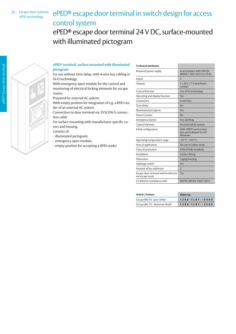
ePED® terminal, surface-mounted with illuminated pictogramFor use without time delay, with 4-wire bus cabling in Hi-O technology.With emergency open module for the control and monitoring of electrical locking elements for escape routes.Prepared for external AC system.With empty position for integration of e.g. a RFID rea-der of an external AC system.Connection to door terminal via: SYSCON-5 connec-tion cableFor surface mounting with manufacturer-specific co-vers and housing.Consists of: ∙ illuminated pictogram; ∙ emergency open module; ∙ empty position for accepting a RFID reader
Article / Feature Order no.
Gira profile 55 - pure white 1 3 8 6 - 1 L B 7 - - 0 4 0 0
Gira profile 55 - aluminum finish 1 3 8 6 - 1 L B 7 - - 3 5 0 0

31 Escape door systemsePED technology
ePED
® E
scap
e do
or te
rmin
al
ePED® escape door terminal in switch design for access control systemePED® escape door terminal 24 V DC, surface-mounted with illuminated pictogram
Technical attributes
Required power supply in accordance with DIN EN 60950-1 SELV 24 V (+/-15 %)
Inputs 2
Outputs 1 x 30 V / 1 A switchover contact
Control function Yes, Hi-O technology
Operating and display function Yes
Connection 4-wire bus
Time delay No
Illuminated pictogram Yes
Down Counter No
Emergency button Yes, latching
Control element Via external AC system
Initial configuration With ePED® service inter-face and software for MS Windows
Operating temperature range -10 °C – +55 °C
Area of application For use in indoor areas
Class of protection IP30 (if fully installed)
Installation Surface fitting
Dimension 3 gang housing
Sabotage switch Yes
Amount of bus addresses 3
Escape door terminal with bi-directio-nal escape route
Yes
Certified in compliance with EltVTR; DIN EN 13637:2015
ePED® terminal, surface-mounted with illuminated pictogram, included 1386S00UPFor use without time delay, with 4-wire bus cabling in Hi-O technology.With emergency open module for the control and monitoring of electrical locking elements for escape routes.Prepared for external AC system.With empty position for integration of e.g. a RFID rea-der of an external AC system.Connection to door terminal via: SYSCON-5 connec-tion cableFor surface mounting with manufacturer-specific co-vers and housing.Consists of: ∙ illuminated pictogram; ∙ emergency open module; ∙ empty position for accepting a RFID reader
With ePED® interface for locks for installation in distri-bution boxes
Article / Feature Order no.
Gira profile 55 - pure white; incl. 1386S00UP
1 3 8 6 - 1 L B 7 - - 0 4 S 0
Gira profile 55 - aluminum finish; incl. 1386S00UP
1 3 8 6 - 1 L B 7 - - 3 5 S 0

Escape door systemsePED technology
32
ePED
® E
scap
e do
or te
rmin
al
ePED® escape door terminal in switch design for access control systemePED® escape door terminal 24 V DC, flush-mounted for time delay and illuminated pictogram
Technical attributes
Required power supply in accordance with DIN EN 60950-1 SELV 24 V (+/-15 %)
Inputs 2
Outputs 1 x 30 V / 1 A switchover contact
Control function Yes, Hi-O technology
Operating and display function Yes
Connection 4-wire bus
Time delay Yes
Illuminated pictogram Yes
Down Counter Yes
Emergency button Yes, latching
Control element Via external AC system
Initial configuration With ePED® service inter-face and software for MS Windows
Operating temperature range -10 °C – +55 °C
Area of application For use in indoor areas
Class of protection IP30 (if fully installed)
Installation in DIN switch boxes >= 62.5 mm deep
Dimension 4 gang switch combination
Sabotage switch Yes
Amount of bus addresses 3
Escape door terminal with bi-directio-nal escape route
Yes
Certified in compliance with EltVTR; DIN EN 13637:2015
ePED® terminal, flush-mounted with time delay and illuminated pictogramFor use with time delay, with 4-wire bus cabling in Hi-O technology.With emergency open module for the control and monitoring of electrical locking elements for escape routes.The time delay deviating from this is checked as per the requirements of DIN EN 13637:2015 (electrically controlled exit systems for use on escape routes) as per EN 61508 Safety Integrity Level 2 (SIL2).Time delay applications are subject to local Building Regulations. Additional permissions may be reqired.Prepared for external AC system.With empty position for integration of e.g. a RFID rea-der of an external AC system.Connection to door terminal via: SYSCON-5 connec-tion cableFor mounting in DIN switch boxes for light switch sys-tems with manufacturer-specific covers and frames.Consists of: ∙ illuminated pictogram; ∙ display release delay; ∙ emergency open module; ∙ empty position for accepting a RFID reader
Article / Feature Order no.
Jung AS500 - alpine white 1 3 8 6 Z 1 L B 1 - - 0 4 0 0
Jung AS500; green 1 3 8 6 Z 1 L B 1 - - 1 8 0 0
Jung LS 990 - alpine white 1 3 8 6 Z 1 L B 6 - - 0 4 0 0
Jung LS 990 - stainless steel 1 3 8 6 Z 1 L B 6 3 5 3 5 0 0
Gira E2 - gloss pure white 1 3 8 6 Z 1 L B 2 - - 0 4 0 0
Gira E2 – aluminium finish 1 3 8 6 Z 1 L B 2 - - 3 5 0 0
Gira Standard 55 - glossy, pure white 1 3 8 6 Z 1 L B 3 - - 0 4 0 0
Gira Stainless Steel Series 21 1 3 8 6 Z 1 L B 5 3 5 3 5 0 0

33 Escape door systemsePED technology
ePED
® E
scap
e do
or te
rmin
al
ePED® escape door terminal in switch design for access control systemePED® escape door terminal 24 V DC, flush-mounted for time delay and illuminated pictogram
Technical attributes
Required power supply in accordance with DIN EN 60950-1 SELV 24 V (+/-15 %)
Inputs 2
Outputs 1 x 30 V / 1 A switchover contact
Control function Yes, Hi-O technology
Operating and display function Yes
Connection 4-wire bus
Time delay Yes
Illuminated pictogram Yes
Down Counter Yes
Emergency button Yes, latching
Control element Via external AC system
Initial configuration With ePED® service inter-face and software for MS Windows
Operating temperature range -10 °C – +55 °C
Area of application For use in indoor areas
Class of protection IP30 (if fully installed)
Installation in DIN switch boxes >= 62.5 mm deep
Dimension 4 gang switch combination
Sabotage switch Yes
Amount of bus addresses 4
Escape door terminal with bi-directio-nal escape route
Yes
Certified in compliance with EltVTR; DIN EN 13637:2015
ePED® terminal, flush-mounted with time delay and illuminated pictogram included 1386S00UPFor use with time delay, with 4-wire bus cabling in Hi-O technology.With emergency open module for the control and monitoring of electrical locking elements for escape routes.The time delay deviating from this is checked as per the requirements of DIN EN 13637:2015 (electrically controlled exit systems for use on escape routes) as per EN 61508 Safety Integrity Level 2 (SIL2).Time delay applications are subject to local Building Regulations. Additional permissions may be reqired.Prepared for external AC system.With empty position for integration of e.g. a RFID rea-der of an external AC system.Connection to door terminal via: SYSCON-5 connec-tion cableFor mounting in DIN switch boxes for light switch sys-tems with manufacturer-specific covers and frames.Consists of: ∙ illuminated pictogram; ∙ display release delay; ∙ emergency open module; ∙ empty position for accepting a RFID reader
With ePED® interface for locks for installation in distri-bution boxes
Article / Feature Order no.
Jung AS500 - alpine white; incl. 1386S00UP
1 3 8 6 Z 1 L B 1 - - 0 4 S 0
Jung AS500 - green; incl. 1386S00UP 1 3 8 6 Z 1 L B 1 - - 1 8 S 0
Jung LS 990 - alpine white; incl. 1386S00UP
1 3 8 6 Z 1 L B 6 - - 0 4 S 0
Jung LS 990 - stainless steel; incl. 1386S00UP
1 3 8 6 Z 1 L B 6 3 5 3 5 S 0
Gira E2 - gloss pure white; incl. 1386S00UP
1 3 8 6 Z 1 L B 2 - - 0 4 S 0
Gira E2 – aluminum finish; incl. 1386S00UP
1 3 8 6 Z 1 L B 2 - - 3 5 S 0
Gira standard 55 - gloss pure white; incl. 1386S00UP
1 3 8 6 Z 1 L B 3 - - 0 4 S 0
Gira stainless steel Series 21; incl. 1386S00UP
1 3 8 6 Z 1 L B 5 3 5 3 5 S 0

Escape door systemsePED technology
34
ePED
® E
scap
e do
or te
rmin
al
ePED® escape door terminal in switch design for access control systemePED® escape door terminal 24 V DC, surface-mounted for time delay and illuminated pictogram
Technical attributes
Required power supply in accordance with DIN EN 60950-1 SELV 24 V (+/-15 %)
Inputs 2
Outputs 1 x 30 V / 1 A switchover contact
Control function Yes, Hi-O technology
Operating and display function Yes
Connection 4-wire bus
Time delay Yes
Illuminated pictogram Yes
Down Counter Yes
Emergency button Yes, latching
Control element Via external AC system
Initial configuration With ePED® service inter-face and software for MS Windows
Operating temperature range -10 °C – +55 °C
Area of application For use in indoor areas
Class of protection IP30 (if fully installed)
Installation Surface fitting
Dimension 5 gang housing
Sabotage switch Yes
Amount of bus addresses 3
Escape door terminal with bi-directio-nal escape route
Yes
Certified in compliance with EltVTR; DIN EN 13637:2015
ePED® terminal, surface-mounted with time delay and illuminated pictogramFor use with time delay, with 4-wire bus cabling in Hi-O technology.With emergency open module for the control and monitoring of electrical locking elements for escape routes.The time delay deviating from this is checked as per the requirements of DIN EN 13637:2015 (electrically controlled exit systems for use on escape routes) as per EN 61508 Safety Integrity Level 2 (SIL2).Time delay applications are subject to local Building Regulations. Additional permissions may be reqired.Prepared for external AC system.With empty position for integration of e.g. a RFID rea-der of an external AC system.Connection to door terminal via: SYSCON-5 connec-tion cableFor surface mounting with manufacturer-specific co-vers and housing.Consists of: ∙ illuminated pictogram; ∙ central cover; display release delay; ∙ emergency open module; ∙ empty position for accepting a RFID reader
Article / Feature Order no.
Gira profile 55 - pure white 1 3 8 6 Z 1 L B 7 - - 0 4 0 0
Gira profile 55 - aluminum finish 1 3 8 6 Z 1 L B 7 - - 3 5 0 0

35 Escape door systemsePED technology
ePED
® E
scap
e do
or te
rmin
al
ePED® escape door terminal in switch design for access control systemePED® escape door terminal 24 V DC, surface-mounted for time delay and illuminated pictogram
Technical attributes
Required power supply in accordance with DIN EN 60950-1 SELV 24 V (+/-15 %)
Inputs 2
Outputs 1 x 30 V / 1 A switchover contact
Operating and display function Yes
Control function Yes, Hi-O technology
Connection 4-wire bus
Time delay Yes
Illuminated pictogram Yes
Down Counter Yes
Emergency button Yes, latching
Control element Via external AC system
Initial configuration With ePED® service inter-face and software for MS Windows
Operating temperature range -10 °C – +55 °C
Area of application For use in indoor areas
Class of protection IP30 (if fully installed)
Installation Surface fitting
Dimension 5 gang housing
Sabotage switch Yes
Amount of bus addresses 4
Escape door terminal with bi-directio-nal escape route
Yes
Certified in compliance with EltVTR; DIN EN 13637:2015
ePED® terminal, surface-mounted with time delay and illuminated pictogramFor use with time delay, with 4-wire bus cabling in Hi-O technology.With emergency open module for the control and monitoring of electrical locking elements for escape routes.The time delay deviating from this is checked as per the requirements of DIN EN 13637:2015 (electrically controlled exit systems for use on escape routes) as per EN 61508 Safety Integrity Level 2 (SIL2).Time delay applications are subject to local Building Regulations. Additional permissions may be reqired.Prepared for external AC system.With empty position for integration of e.g. a RFID rea-der of an external AC system.Connection to door terminal via: SYSCON-5 connec-tion cableFor surface mounting with manufacturer-specific co-vers and housing.Consists of: ∙ illuminated pictogram; ∙ central cover; display release delay; ∙ emergency open module; ∙ empty position for accepting a RFID reader
With ePED® interface for locks for installation in distri-bution boxes
Article / Feature Order no.
Gira profile 55 - pure white; incl. 1386S00UP
1 3 8 6 Z 1 L B 7 - - 0 4 S 0
Gira profile 55 - aluminum finish; incl. 1386S00UP
1 3 8 6 Z 1 L B 7 - - 3 5 S 0

Escape door systemsePED technology
36
ePED
® E
scap
e do
or te
rmin
al
ePED® Escape door terminal in switch design Individual modules and Accessories
Technical attributes
Installation To install flush mounted switch box, 62 mm deep, frame or surface housing necessary
Inputs 2
Outputs 1 x 30 V / 1 A switchover contact
Certified in compliance with EltVTR; DIN EN 13637:2015
Control function Yes, Hi-O technology
Operating and display function Yes, integrated
Connection 4-wire bus; SYSCON 4
Emergency button Yes, latching
Control element No, external operating unit required
Initial configuration With ePED® service inter-face and software for MS Windows
Required power supply in accordance with DIN EN 60950-1 SELV; 12 V (–15 %) to 24 V (+15 %); optimal voltage = 24 VDC
Operating temperature range -10 °C – +55 °C
Area of application For use in indoor areas
Class of protection IP30 (if fully installed)
Sabotage switch Yes
Amount of bus addresses 2
Escape door terminal with bi-directio-nal escape route
Yes
ePED® EMERGENCY OPEN moduleSingle module in Hi-O bus technology with optimized operating concept. To control locking/unlocking, tem-porary unlocking, alarm acknowledgement through a potencial-free contact such as card reader, door code systems or others. Or to conventionally control th-rough key switch, tested in compliace with EltVTR.
∙ Emergency button lights up; features reusable, non-detachable, shatterproof protective cover
∙ Integrated visual door status indicator with high-per-formance LEDs (green / red / yellow) signalling unlo-cked / locked / alarm status
∙ Emergency button sign (arrow pointing downwards) ∙ Acoustic signal and tampering contact ∙ Adjustable time period for delayed permanent re-
lease, temporary release, pre-alarm, alarm interval, guidance signal
∙ Monitoring of time door is open in the case of tem-porary unlocking
∙ With two inputs featuring adjustable parameters for: - control via an external operating element or; - temporary release via AC system or; - emergency locking via fire alarm system or; - unlocking via switching timer.
∙ With a relay output featuring adjustable parameters for: - door locked/unlocked, - door open/closed, - common alarm, - individual alarm or - activation of electric strike/ motorized lock/ revol-ving door drive/ arrestor system.
∙ System connector for setting parameters with ePED® service interface and software for MS Windows
∙ Connections: - SYSCON-4: Hi-O bus; - SYSCON-5: operating unit, - screw/ plug-in terminals
Article / Feature Order no.
Standard for 55 mm modules 1 3 8 6 D 0 0 - - - - - - 0 0

37 Escape door systemsePED technology
ePED
® E
scap
e do
or te
rmin
al
ePED® Escape door terminal in switch design Individual modules and Accessories
Technical attributes
Installation To install flush mounted switch box, 62 mm deep, frame or surface housing necessary
Control function No, Hi-O technology
Connection 4-wire bus; SYSCON 4
Time delay Yes
Required power supply in accordance with DIN EN 60950-1 SELV; 12 V (–15 %) to 24 V (+15 %); optimal voltage = 24 VDC
Operating temperature range -10 °C – +55 °C
Area of application For use in indoor areas
Class of protection IP30 (if fully installed)
Sabotage switch No
Amount of bus addresses 1
Escape door terminal with bi-directio-nal escape route
Yes
Certified in compliance with DIN EN 13637:2015
ePED® release delay displayIndividual module in Hi-O bus technology for display-ing the expiring time delay.Integrated visual door status indicator with high-per-formance LEDs (green / red / yellow) signalling unlo-cked / locked / alarm status
Article / Feature Order no.
Standard for 55 mm modules 1 3 8 6 D 0 0 - C o u n - 0 0
Technical attributes
Required power supply in accordance with DIN EN 60950-1 SELV 24 V (+/-15 %)
Installation Frame or surface-mounted module required to install flush-mounted switch boxes 45 mm deep
Connection SYSCON 4
Operating temperature range -10 °C – +55 °C
Area of application For use in indoor areas
Class of protection IP30 (if fully installed)
Sabotage switch No
Amount of bus addresses none
Certified in compliance with EltVTR; DIN EN 13637:2015
Illuminated information pictogram module for esca-pe routesFor marking of the emergency button in electrical con-trolled escape route system.With active background lightening and with self-adhe-sive pictogram according to DIN EN 13637:2015.For the connection with effeff escape route terminals 1383/1384/1385/1386D00 through standard system plug.Cable is included in the scope of delivery.The use is possible in combination with door terminal 1380.Suitable for 55 mm frames.
Article / Feature Order no.
Illuminated pictogram 1 3 8 6 D 0 0 - H W - - F 9 0

Escape door systemsePED technology
38
ePED
® E
scap
e do
or te
rmin
al
ePED® Escape door terminal in switch design Individual modules and accessories
Technical attributes
Operating and display function Operating function
Connection SYSCON 5
Control element Key switch with Euro profile cylinder; adjustable cam posi-tion 8 x 45°; 30.5 mm long
Operating temperature range -10 °C – +55 °C
Area of application For use in indoor areas
Class of protection IP30 (if fully installed)
Installation Frame or surface-mounted module required to install flush-mounted switch boxes 45 mm deep
Sabotage switch Yes
Connections (key switch) Screw/ plug-in terminals
Amount of bus addresses none
Key switch on opposite side to direc-tion of escape
Yes (without display)
Key switch module model 1385ES2Key switch for connection to an effeff escape door control module or door monitoring module for con-trolling unlocking, locking, temporary unlocking and alarm resetting, integrated tamper contact
Key switch module ∙ For standard flush-mounted boxes: 45 mm depth, with Euro profile half-cylinder, cam position 180°, length 30.5 mm
∙ Connection: SYSCON-5 and screw/ plug-in terminals
Article / Feature Order no.
System 55, Jung AS500, alpine white 1 3 8 5 E S 2 - 1 - - 0 4 0 0
System 55, Jung AS500, green 1 3 8 5 E S 2 - 1 - - 1 8 0 0
System 55, Gira E2; pure white gloss 1 3 8 5 E S 2 - 2 - - 0 4 0 0
System 55, Gira E2, aluminium finish 1 3 8 5 E S 2 - 2 - - 3 5 0 0
System 55, Gira Standard 55; pure white gloss
1 3 8 5 E S 2 - 3 - - 0 4 0 0
System 55, Gira series 21, stainless steel
1 3 8 5 E S 2 - 5 3 5 3 5 0 0
System 55, Jung LS990, alpine white 1 3 8 5 E S 2 - 6 - - 0 4 0 0
System 55, Jung LS990, stainless steel 1 3 8 5 E S 2 - 6 3 5 3 5 0 0
Technical attributes
System 55 mm
Main Cover Model 1385EZATo cover the power supply module
Article / Feature Order no.
Jung AS500 - alpine white 1 3 8 5 E Z A - 1 - - 0 4 0 0
Jung AS500; green 1 3 8 5 E Z A - 1 - - 1 8 0 0
Jung LS990 - alpine white 1 3 8 5 E Z A - 6 - - 0 4 0 0
Jung LS990 - stainless steel 1 3 8 5 E Z A - 6 3 5 3 5 0 0
Gira E2 - gloss pure white 1 3 8 5 E Z A - 2 - - 0 4 0 0
Gira E2; aluminium colour 1 3 8 5 E Z A - 2 - - 3 5 0 0
Gira Standard 55 - glossy, pure white 1 3 8 5 E Z A - 3 - - 0 4 0 0
Gira Series 21, stainless steel 1 3 8 5 E Z A - 5 3 5 3 5 0 0

39 Escape door systemsePED technology
ePED
® E
scap
e do
or te
rmin
al
ePED® Escape door terminal in switch design Individual modules and accessories
Technical attributes
Sockets SYSCON 4 on both sides
Syscon 4 Connecting Cable Model 1385EVL4To connect panels. The single conductors are highligh-ted in color.
Article / Feature Order no.
Syscon-4; double sided; 4-pin female connector
1 3 8 5 E V L 4 - - - - - 0 0
Technical attributes
Sockets SYSCON 5 on both sides
Syscon 5 Connecting Cable Model 1385EVL5To connect the escape door control unit with the key switch unit. The single conductors are highlighted in color.
Article / Feature Order no.
Syscon-5; double-sided; 5-pin female connector
1 3 8 5 E V L 5 - - - - - 0 0
Technical attributes
Sockets SYSCON-7 on both sides
Connecting cable Syscon-7To connect additional control and status signals. The single conductors are highlighted in color.
Article / Feature Order no.
Syscon-7 on both sides, 7-pole socket 1 3 8 5 E V L 7 - - - - - 0 0
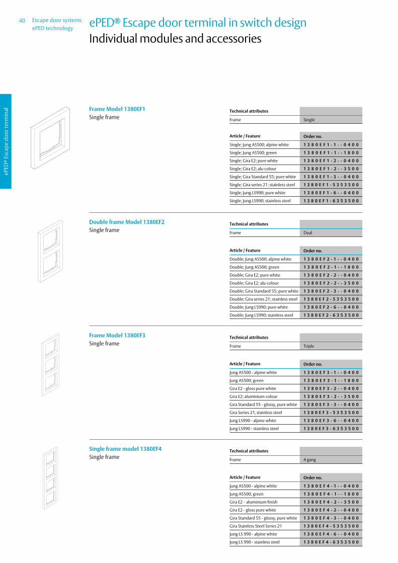
Escape door systemsePED technology
40
ePED
® E
scap
e do
or te
rmin
al
ePED® Escape door terminal in switch design Individual modules and accessories
Technical attributes
Frame Single
Frame Model 1380EF1Single frame
Article / Feature Order no.
Single; Jung AS500; alpine white 1 3 8 0 E F 1 - 1 - - 0 4 0 0
Single; Jung AS500; green 1 3 8 0 E F 1 - 1 - - 1 8 0 0
Single; Gira E2; pure white 1 3 8 0 E F 1 - 2 - - 0 4 0 0
Single; Gira E2; alu colour 1 3 8 0 E F 1 - 2 - - 3 5 0 0
Single; Gira Standard 55; pure white 1 3 8 0 E F 1 - 3 - - 0 4 0 0
Single; Gira series 21; stainless steel 1 3 8 0 E F 1 - 5 3 5 3 5 0 0
Single; Jung LS990; pure white 1 3 8 0 E F 1 - 6 - - 0 4 0 0
Single; Jung LS990; stainless steel 1 3 8 0 E F 1 - 6 3 5 3 5 0 0
Technical attributes
Frame Dual
Double frame Model 1380EF2Single frame
Article / Feature Order no.
Double; Jung AS500; alpine white 1 3 8 0 E F 2 - 1 - - 0 4 0 0
Double; Jung AS500; green 1 3 8 0 E F 2 - 1 - - 1 8 0 0
Double; Gira E2; pure white 1 3 8 0 E F 2 - 2 - - 0 4 0 0
Double; Gira E2; alu colour 1 3 8 0 E F 2 - 2 - - 3 5 0 0
Double; Gira Standard 55; pure white 1 3 8 0 E F 2 - 3 - - 0 4 0 0
Double; Gira series 21; stainless steel 1 3 8 0 E F 2 - 5 3 5 3 5 0 0
Double; Jung LS990; pure white 1 3 8 0 E F 2 - 6 - - 0 4 0 0
Double; Jung LS990; stainless steel 1 3 8 0 E F 2 - 6 3 5 3 5 0 0
Technical attributes
Frame Triple
Frame Model 1380EF3Single frame
Article / Feature Order no.
Jung AS500 - alpine white 1 3 8 0 E F 3 - 1 - - 0 4 0 0
Jung AS500; green 1 3 8 0 E F 3 - 1 - - 1 8 0 0
Gira E2 - gloss pure white 1 3 8 0 E F 3 - 2 - - 0 4 0 0
Gira E2; aluminium colour 1 3 8 0 E F 3 - 2 - - 3 5 0 0
Gira Standard 55 - glossy, pure white 1 3 8 0 E F 3 - 3 - - 0 4 0 0
Gira Series 21, stainless steel 1 3 8 0 E F 3 - 5 3 5 3 5 0 0
Jung LS990 - alpine white 1 3 8 0 E F 3 - 6 - - 0 4 0 0
Jung LS990 - stainless steel 1 3 8 0 E F 3 - 6 3 5 3 5 0 0
Technical attributes
Frame 4 gang
Single frame model 1380EF4Single frame
Article / Feature Order no.
Jung AS500 - alpine white 1 3 8 0 E F 4 - 1 - - 0 4 0 0
Jung AS500; green 1 3 8 0 E F 4 - 1 - - 1 8 0 0
Gira E2 – aluminium finish 1 3 8 0 E F 4 - 2 - - 3 5 0 0
Gira E2 - gloss pure white 1 3 8 0 E F 4 - 2 - - 0 4 0 0
Gira Standard 55 - glossy, pure white 1 3 8 0 E F 4 - 3 - - 0 4 0 0
Gira Stainless Steel Series 21 1 3 8 0 E F 4 - 5 3 5 3 5 0 0
Jung LS 990 - alpine white 1 3 8 0 E F 4 - 6 - - 0 4 0 0
Jung LS 990 - stainless steel 1 3 8 0 E F 4 - 6 3 5 3 5 0 0

41 Escape door systemsePED technology
ePED
® E
scap
e do
or te
rmin
al
ePED® Escape door terminal in switch design Individual modules and accessories
Technical attributes
System 55 mm
Intermediary Frame Model 1385EF1ZIntermediary frame for 55 mm switch modules.
Article / Feature Order no.
Gira Serie 21 on 55x55 mm 1 3 8 0 E F 1 Z 5 - - - - 0 0
Jung LS990; alpine white; for 55x55 mm
1 3 8 0 E F 1 Z 6 - - 0 4 0 0
Jung LS990 stainless steel (aluminium colour) on 55x55 mm
1 3 8 0 E F 1 Z 6 - - 3 5 0 0

Escape door systemsePED technology
42
ePED
® E
scap
e do
or te
rmin
al
ePED® Escape door terminal in switch design Individual modules and accessories
Technical attributes
Frame Single
Mounting method Surface-mounted
Housing for Model 1385EG1Housing
Article / Feature Order no.
Single; Gira Profil 55, pure white 1 3 8 5 E G 1 - 7 - - 0 4 0 0
Single; Gira Profil 55, aluminium finish 1 3 8 5 E G 1 - 7 - - 3 5 0 0
Technical attributes
Frame Dual
Mounting method Surface-mounted
Housing for Model 1385EG2Housing
Article / Feature Order no.
Double; Gira Profil 55, pure white 1 3 8 5 E G 2 - 7 - - 0 4 0 0
Double; Gira Profil 55, aluminium finish
1 3 8 5 E G 2 - 7 - - 3 5 0 0
Technical attributes
Frame Triple
Mounting method Surface-mounted
Housing for Model 1385EG3Housing
Article / Feature Order no.
Triple; Gira Profil 55, pure white 1 3 8 5 E G 3 - 7 - - 0 4 0 0
Triple; Gira Profil 55, aluminium finish 1 3 8 5 E G 3 - 7 - - 3 5 0 0
87
158
230

43 Escape door systemsePED technology
ePED
® E
scap
e do
or te
rmin
al
ePED® Escape door terminal in switch design Individual modules and accessories
Technical attributes
Frame 5 gang
Mounting method Surface-mounted
Housing model 1385EG5Housing
Article / Feature Order no.
Gira - glossy pure white 1 3 8 5 E G 5 - 7 - - 0 4 0 0
Gira - aluminum colour 1 3 8 5 E G 5 - 7 - - 3 5 0 0
372

Escape door systemsePED technology
44
ePED
® E
scap
e do
or te
rmin
al
ePED® Escape door terminal in switch design Individual modules and Accessories
Technical attributes
Type of cylinder Designed for with profile half-cylinder; cam position 8 x 45°; 30.5 mm long
LED display No
Mounting method Surface-mounted
Class of protection IP 54
Height 73,5 mm
Width 73,5 mm
Depth 45 mm
Key Switch Model 1140An operating unit to release doors against direction of escape (outdoors) in conjunction with escape door control unit.
Key switch module ∙ With a momentary n.o. contact which can be ope-
rated to the left or right, ∙ For locking/unlocking, temporary releasing ∙ Metal housing ∙ Connections: screw terminals Article / Feature Order no.
With momentary n.o. contact on both sides; surface-mounted
1 1 4 0 - 1 0 - - - - - - 0 0
Technical attributes
Height 100 mm
Mounting method Surface-mounted
Type of cylinder Designed for with profile half-cylinder; cam position 8 x 45°; 30.5 mm long
Depth 56 mm
Class of protection IP 54
Width 90 mm
LED display No
Key Switch Model 1140An operating unit to release doors against direction of escape (outdoors) in conjunction with escape door control unit.
Key switch module ∙ With a momentary n.o. contact which can be opera-ted to the left or right,
∙ For locking/unlocking, temporary releasing ∙ Metal housing ∙ Connections: screw terminals Article / Feature Order no.
With momentary n.o. contact on both sides; flush-mounted
1 1 4 0 - 1 1 - - - - - - 0 0

45 Escape door systemsePED technology
ePED
® E
scap
e do
or te
rmin
al
ePED® Escape door terminal in switch design Individual modules and Accessories
Technical attributes
Dimension 100 x 100 x 3 mm
Escape Route Sign Model 1385-FTSThe mandatory pictogram is printed on a 74 x 74 mm surface on a transparent acrylic panel measuring 100 x 100 x 3 mm.The imprint becomes luminescent after exposure to light for a certain period of time.
Article / Feature Order no.
For mounting on the wall, 100x100x3 mm clamp mounting with accessories
1 3 8 5 - F T S - - - - - 0 0
Technical attributes
Color Green
Dimension approx. 90 x 90 mm
Version Emergency button
Plastic sign model 1386 HWFor labelling the function of the emergency button, without time delay.
Article / Feature Order no.
Green / white base, adhesive 1 3 8 6 - H W - - - - - - 0 0
Technical attributes
Color Green
Dimension approx. 90 x 90 mm
Version Emergency button
Plastic sign model 1386-HWTFor labelling the function of the emergency button, with time delay.
Article / Feature Order no.
Green / white base, adhesive, with time delay
1 3 8 6 - H W T - - - - - 0 0
Technical attributes
For Product Alle Terminals
Inspection Sticker Model 2.1502-00030000For all terminals
Article / Feature Order no.
Inscription: Escape door locking system (Label only in German)
2 . 1 5 0 2 - 0 0 0 3 0 0 0 0

Escape door systemsePED technology
46
ePED
® E
scap
e do
or te
rmin
al
Escape Door LockingePED® Interface for locking
Technical attributes
Control function Yes, Hi-O technology
Connection 4-wire bus
Time delay Yes
Required power supply in accordance with DIN EN 60950-1 SELV; 12 V (–15 %) to 24 V (+15 %); optimal voltage = 24 VDC
Operating temperature range -10 °C – +55 °C
Area of application For use in indoor areas
Class of protection IP30 (if fully installed)
Installation For mounting in distributor or junction boxes.
Dimension 59 x 52 x 20 mm
Sabotage switch No
Amount of bus addresses 1
Certified in compliance with EltVTR; DIN EN 13637:2015
ePED® interface for locks for installationSystem interfaces with safety functions for the connection of approved escape-door locking systems. For mounting in distributor or junction boxes.
Article / Feature Order no.
for installation in distribution box 1 3 8 6 S 0 0 U P - - - - 0 0
Technical attributes
Control function Yes, Hi-O technology
Connection 4-wire bus
Time delay Yes
Required power supply in accordance with DIN EN 60950-1 SELV; 12 V (–15 %) to 24 V (+15 %); optimal voltage = 24 VDC
Operating temperature range -10 °C – +55 °C
Area of application For use in indoor areas
Class of protection IP30
Installation To fit on mounting rails in distributor housings.
Dimension 98 x 88 x 63 mm (H x W x D)
Sabotage switch No
Amount of bus addresses 1
Certified in compliance with EltVTR; DIN EN 13637:2015
ePED® interface for locks for distribution box installationSystem interfaces with safety functions for the connec-tion of approved escape-door locking systems. To fit on mounting rails in distributor housings.
Article / Feature Order no.
for distribution box installation 1 3 8 6 S 0 0 V T - - - - 0 0

47 Escape door systemsePED technology
ePED
® E
scap
e do
or te
rmin
al
Escape Door LockingePED® Interface for locking
Technical attributes
Control function Yes, Hi-O technology
Connection 4-wire bus
Time delay Yes
Required power supply in accordance with DIN EN 60950-1 SELV; 12 V (–15 %) to 24 V (+15 %); optimal voltage = 24 VDC
Operating temperature range -10 °C – +55 °C
Area of application For use in indoor areas
Class of protection IP30
Installation For surface mounting in dry rooms.
Dimension 125 x 80 x 41 mm (H x W x D)
Sabotage switch No
Amount of bus addresses 1
Certified in compliance with EltVTR; DIN EN 13637:2015
ePED® interface for locks in surface-mounted housingSystem interfaces with safety functions for the connection of approved escape-door locking systems. For surface mounting in dry rooms.
Article / Feature Order no.
in surface-mounted housing 1 3 8 6 S 0 0 A P - - - - 0 0
Technical attributes
Area of application For use in indoor areas
Class of protection IP30
Installation To fit on mounting rails in distributor housings.
Dimension 98 x 88 x 63 mm (H x W x D)
Sabotage switch No
Housing for 1386S00UP for distribution box instal-lationFor the installation of the ePED® interface for lockings 1386S00UP. To fit on mounting rails in distributor housings
Article / Feature Order no.
for distribution box installation 1 3 8 6 E - V T - - - - - 0 0
Technical attributes
Area of application For use in indoor areas
Class of protection IP30
Installation For surface mounting in dry rooms.
Dimension 125 x 80 x 41 mm (H x W x D)
Sabotage switch No
Housing for 1386S00UP for surface mountingFor the installation of the ePED® interface for lockings 1386S00UP. For surface mounting in dry rooms.
Article / Feature Order no.
for surface mounting 1 3 8 6 E - A P - - - - - 0 0

Escape door systemsePED technology
48
ePED
® E
scap
e do
or te
rmin
al
Escape Door LockingPower supply
Technical attributes
Class of protection IP20
Material housing plastic
Power supplyThere is a suitable power supply unit for each type of use. The individual power supply units stand out due to their constant output voltage during fluctuations in mains voltage and load alternation.These stabilised power supply units are used for ac-cess control, escape route systems and electric strike systems where a low-noise locking component is required.
Article / Feature Order no.
1 A, (W/D/H) 35,5x66x85 mm 1 0 0 3 - 2 4 - 1 - - - - 1 0
2 A, (W/D/H) 70x68,5x93 mm 1 0 0 3 - 2 4 - 2 - - - - 1 0
4 A, (W/D/H) 70x68,5x93 mm 1 0 0 3 - 2 4 - 4 - - - - 1 0
Technical attributes
Output voltage 24 V DC (regulated)
Input operating voltage 230 V AC/ ± 15 %; 50/60 Hz
Version in steel housing with top hat rail
Dimension 300 mm x 186 mm x 125 mm
Class of protection IP 30
Protection rating I
Color Grey white (RAL 9002)
Operating temperature range -10 °C to + 40 °C
Function indicator LED display
Announcements charge battery / Output voltage available / Battery voltage available / Battery in conservation charge / system voltage available
Outputs for messages Open Collector max . 24 V DC 30 mA
Connection Connection terminal
Certified in compliance with DIN EN 60950-1 SELV
Rated power output 72 W
Recommended accumulator 2 x 18003--------00
Emergency power supply with two batteries in the steel housing with top-hat railUninterruptible emergency power supply with integ-rated charging stage and battery management, with signal outputs for remote monitoring in stabilised steel sheet housing including rechargeable battery/ batteries. Connection terminals for load and battery. Only for hermetically sealed lead batteries.
Article / Feature Order no.
24 V DC 3A in housing with two batteries 18003
1 0 0 6 - 2 4 0 3 0 S G - 0 0
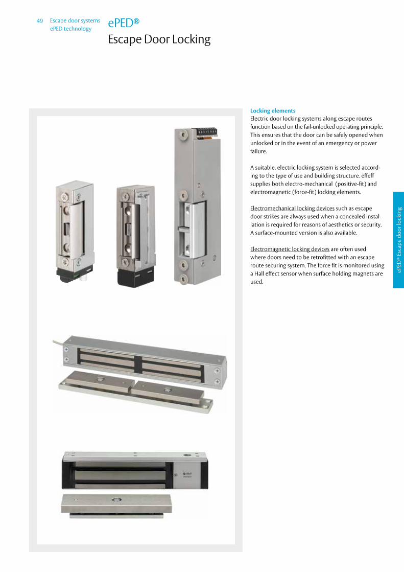
49 Escape door systemsePED technology
ePED
® E
scap
e do
or lo
ckin
g
ePED®
Escape Door Locking
Locking elementsElectric door locking systems along escape routes function based on the fail-unlocked operating principle.This ensures that the door can be safely opened when unlocked or in the event of an emergency or power failure.
A suitable, electric locking system is selected accord-ing to the type of use and building structure. effeff supplies both electro-mechanical (positive-fit) and electromagnetic (force-fit) locking elements.
Electromechanical locking devices such as escape door strikes are always used when a concealed instal-lation is required for reasons of aesthetics or security. A surface-mounted version is also available.
Electromagnetic locking devices are often used where doors need to be retrofitted with an escape route securing system. The force fit is monitored using a Hall effect sensor when surface holding magnets are used.

Escape door systemsePED technology
50
ePED
® E
scap
e do
or lo
ckin
g
Locking elementsEscape door strike 332.80Fail-unlocked
The compact design of the new effeff escape door strike 332 is comparable with a standard electric strike, thus guaranteeing fast, simple installation in a wide variety of different profiles and frames.
The advantages at a glance ∙ Radius latch ∙ Compact design ∙ Min. 2000 N, max. 3000 N holding power according to prEN13633 and prEN 13637
∙ Unlocking under preload with 100% holding power ∙ Monitoring contact is potential-free and armature contact is non-isolated * ∙ Suitable for DL/DR and horizontal installation ∙ Low power consumption ∙ Compact fitting dimensions ∙ Adjustable FaFix® latch: 2 mm adjustment range with 0.5 mm increments ∙ Adjustable via Fix grooves in housing
Characteristics
Adjustable latch (FF, FaFix®) •
Monitoring contact (RR) •
Diode (05) •
Fail-locked
Fail-unlocked •
DIN door swing directions
Universal 1
Voltage
12 V DC E924 V DC F9
Order no.
332.80------ * * 1
Technical attributes
Break-in resistance 3000 N
Height 77,6 mm
Width 28 mm
Depth 20 mm
Latch bolt engaging depth 6 mm
FaFix® adjustment range 2 mm
Max. pre-load 3000 N
Operating temperature range -15 °C to +40 °C
Continuous function load cycles 200000
Load cycles for in-plant test 500000
Installation position vertical and horizontal
Anchor contact Yes
Switching capacity - monitoring contact 24 V/ 1 A
Input operating voltage ± 10% ± 10%
Rated resistance 63 Ω 260 Ω
Current consumption DC (stabilised) 200 mA 100 mA
Electrical data 12 V DC 24 V DC
Certified escape door strike 332

51 Escape door systemsePED technology
ePED
® E
scap
e do
or lo
ckin
g
Short flat striking plate with latch bolt aperture.
The advantages at a glance ∙ DIN left and right usable
Locking elementsShort flat striking plate no. 096, square-cut
Finish DIN direction Order no.
01 Ducat gold 1 Universal -------09601-01
02 Dusty grey 1 Universal -------09602-01
35 Stainless steel 1 Universal -------09635-01
40 Smoothed, galvanised 1 Universal -------09640-01
Technical attributes
Length 130 mm
Width 24 mm
Thickness 3 mm
Dead bolt cutout No
Latch bolt guide No
x measurement 0 - 4 mm
∙ 332.80Compatible electric strike models

Escape door systemsePED technology
52
ePED
® E
scap
e do
or lo
ckin
g
Short angled striking plate with latch bolt aperture.
The advantages at a glance ∙ Can be used for left and right hand doors
Locking elementsShort angled striking plate no. 603
Technical attributes
Length 130 mm
Width 25/32 mm
Thickness 2 mm
Dead bolt cutout No
Latch bolt guide Yes
Finish DIN direction Order no.
35 Stainless steel 1 Universal -------60335-01
∙ 332.80Compatible electric strike models

53 Escape door systemsePED technology
ePED
® E
scap
e do
or lo
ckin
g
Locking elementsFail-Unlocked 332.208 ProFix® 1
The compact design of the new effeff Escape Door Strike 332 is comparable with a standard electric strike, thus guaranteeing fast, simple installation in a wide variety of different profiles and frames.
The advantages at a glance ∙ Radius latch ∙ Compact symmetrical design ∙ Min. 2000 N, max. 3000 N holding power according to prEN13633 and prEN 13637
∙ Unlocking under preload with 100% holding power ∙ Monitoring contact is potential-free and armature contact is non-isolated * ∙ Suitable for DL/DR and horizontal installation ∙ Compact fitting dimensions ∙ Adjustable FaFix® latch: 2 mm adjustment range with 0.5 mm increments ∙ Adjustable via Fix grooves in housing ∙ Compatible with ProFix® 1 striking plates
Characteristics
Adjustable latch (FF, FaFix®) •
Monitoring contact (RR) •
Diode (05) •
Fail-locked
Fail-unlocked •
DIN door swing directions
Universal 1
Voltage
12 V DC E924 V DC F9
Order no.
332.208----- * * 1
Technical attributes
Break-in resistance 3000 N
Height 77,6 mm
Width 28 mm
Depth 20 mm
Latch bolt engaging depth 6 mm
FaFix® adjustment range 2 mm
Max. pre-load 3000 N
Operating temperature range -15 °C to +40 °C
Continuous function load cycles 200000
Load cycles for in-plant test 500000
Installation position vertical and horizontal
Anchor contact Yes
Recovery diode Yes
Switching capacity - monitoring contact 24 V/ 1 A
Input operating voltage ± 10% ± 10%
Rated resistance 63 Ω 260 Ω
Current consumption DC (stabilised) 190 - 200 mA 95 - 100 mA
Electrical data 12 V DC 24 V DC
Certified escape door strike 332

Escape door systemsePED technology
54
ePED
® E
scap
e do
or lo
ckin
g
Short flat striking plate with latch bolt aperture.
The advantages at a glance ∙ DIN left and right usable ∙ For ProFix® model variations
Locking elementsFlat striking plate no. 522, ProFix® 1, square-cut
Finish DIN direction Order no.
35 Stainless steel 1 Universal -------52235-01
Technical attributes
Length 150 mm
Width 34 mm
Thickness 3 mm
Dead bolt cutout No
Latch bolt guide No
x measurement 13,5-15,5 mm
∙ 332.208Compatible electric strike models

55 Escape door systemsePED technology
ePED
® E
scap
e do
or lo
ckin
g
Locking elementsFail-Unlocked 331U80
Escape Door Strike 331U80 is especially designed to lock doors along escape routes. Our Model 331U80 is also suitable as an additional locking device for fire doors. Thanks to its reliable unlocking under preload (max. 5,000 N), it is primarily used in doors which are subject to escape route requirements. The 331U Model Series is guaranteed to work reliably in interlock systems, on soundproof doors and on doors where pressure is expected to act on the electric strike latch due to the structural design.
The advantages at a glance ∙ FaFix® latch with 2 mm adjustment range ∙ Integrated monitoring and armature contact ∙ Sturdy design for demanding requirements
Characteristics
Adjustable latch (FF, FaFix®) •
Monitoring contact (RR) •
Diode (05) •
Armature monitoring contact •
Fail-locked
Fail-unlocked •
DIN door swing directions
Left-hand 4
Voltage
12 V DC E924 V DC F9
Order no.
331U80F----- * * *
Technical attributes
Break-in resistance 5000 N
Height 134 mm
Width 39 mm
Depth 23 mm
Operating temperature range -15 °C to +40 °C
Installation position vertical and horizontal
Operating voltage tolerance range ± 1 V ± 2 V
Rated resistance 37,5 Ω 150 Ω
Current consumption DC (stabilised) 320 mA 160 mA
Max. latch preload DC (stabilised) 5000 N 5000 N
Electrical data 12 V DC 24 V DC
High-security fail-unlocked strike

Escape door systemsePED technology
56
ePED
® E
scap
e do
or lo
ckin
g
Short flat striking plate with latch bolt aperture.
The advantages at a glance ∙ For escape door electric strikes from the 331U Model Range as well as Security
Electric Strike 131
Locking elementsFlat striking plate no. 116For high-security applications
Finish DIN direction Order no.
02 Dusty grey 4 Left-hand -------11602-04
02 Dusty grey 5 Right-hand -------11602-05
35 Stainless steel 4 Left-hand -------11635-04
35 Stainless steel 5 Right-hand -------11635-05
40 Smoothed, galvanised 4 Left-hand -------11640-04
40 Smoothed, galvanised 5 Right-hand -------11640-05
Technical attributes
Length 200 mm
Width 25 mm
Thickness 3 mm
Dead bolt cutout No
Latch bolt guide No
x measurement 2,9-4,9 mm
∙ 331U80 ∙ 331U80F
Compatible electric strike models

57 Escape door systemsePED technology
ePED
® E
scap
e do
or lo
ckin
g
Short angled striking plate with latch bolt aperture.
The advantages at a glance ∙ For fire protection door openers
Locking elementsAngled striking plate no. 090For high-security applications
Finish DIN direction Order no.
35 Stainless steel 4 Left-hand -------09035-04
35 Stainless steel 5 Right-hand -------09035-05
Technical attributes
Length 220 mm
Width 30 mm
Thickness 3 mm
Depth 48 mm
Dead bolt cutout No
Latch bolt guide No
x measurement 3,1-5,1 mm
∙ 331U80 ∙ 331U80F
Compatible electric strike models

Escape door systemsePED technology
58
ePED
® E
scap
e do
or lo
ckin
g
Locking elementsMating components for escape door strikes
Mating component model 807 angularMortise latch bolt locks for Model Series 807 are test-ed in accordance with applicable regulations and are approved as suitable mating components for electrical locking systems in doors along escape routes.The latch bolt is adjustable from 12 mm to 17 mm (projection). This means that it can be adapted to the door gap on site thus ensuring actuation of the moni-toring contact.
Technical attributes
Fixing holes 2
Depth 40 mm
Version Adjustable
Article / Feature Order no.
Faceplate 110 x 24 mm 8 0 7 - 1 0 - - - - - - - 0 0
Faceplate 135 x 20 mm 8 0 7 - 1 1 - - - - - - - 0 0
Mating Component Model 807 RadiusMortise latch bolt locks for Model Series 807 are test-ed in accordance with applicable regulations and are approved as suitable mating components for electrical locking systems in doors along escape routes.The latch bolt is adjustable from 12 mm to 17 mm (projection). This means that it can be adapted to the door gap on site thus ensuring actuation of the moni-toring contact.
Technical attributes
Fixing holes 2
Depth 40 mm
Version Adjustable
Article / Feature Order no.
Faceplate 110 x 24 mm 8 0 7 - 1 2 - - - - - - - 0 0
Faceplate 110 x 20 mm 8 0 7 - 1 3 - - - - - - - 0 0

59 Escape door systemsePED technology
ePED
® E
scap
e do
or lo
ckin
g
Locking elementsMounting accessories for escape door strikes
Surface-Mounted Housing Model A01The solution to installation situations where electric door strikes cannot be installed due to technical dif-ficulties or legal provisions. Installed as an additional locking element, the door is secured in the direction of entry and exit. It is especially suitable for combining with effeff escape route and access control systems.Surface-Mounted Housing A01 integrates Escape Door Electric Strike 331U to safeguard escape routes.Always order compatible Electric Strike Models 131, 141 and 331U with a DIN left handing (4) and in a FaFix design (FF).Comprehensive installation material and drilling tem-plate are included in the supplied package.
Technical attributes
Area of application For metal and wood structures, plastic and aluminium profiles
Dimensions 165 x 57 x 40 mm
Surface Stainless steel
Article / Feature Order no.
1 surface-mounted casing set - - - - - - - A 0 1 3 5 - 0 4
Mounting Bracket Model A03Compatible with Models A01 und A02 for flush-fitted frame-to-door leaf structures.Comprehensive installation material and drilling tem-plate are included in the supplied package.Adjustable throw for projecting door max. 4 mm, for recessed door max. 11 mm
Technical attributes
Dimensions 165 x 46.5 x 46.5 mm
Surface Stainless steel
Article / Feature Order no.
includes installation material and drilling template
- - - - - - - A 0 3 3 5 - 0 1
Blind rivet nut M5 steelCounter-sunk screw M5x25 steel
mating component(hook unit)
Counter-sunk screw M5x15 steel
Strike with mounting plateCover
Frame profile
Door
For steel doors: Screws accessories includedFor wooden doors: Wood screws
Frame profile
Mounting bracket
Blind rivet nut M
8 countersunk scr
Cover
2 countersunk scr
Fix counterplate
2 countersunk scr
2 countersunk scr
Counterplate
Cover
Door strike with
Overall adjustment path
Door

Escape door systemsePED technology
60
ePED
® E
scap
e do
or lo
ckin
g
Locking elementsMounting accessories for escape door strikes
Stainless Steel Adhesive Plate Model A04Adhesive stainless steel plate to fasten the hook bolt in surface mount casing A01 to glass doors and mounting bracket A 03 to the top pane on all-glass doors A combination of adhesive plate A04 with surface mount casing A01 replaces adhesive model A02.Adhesive Plate A04 can also be used to fasten Mount-ing Bracket A03.
Technical attributes
Dimensions 165 x 45 x 3 mm
Version Corner radius 2 mm
System endurance test 250 000 cycles
Load per cycle 140 N (open - close)
Holding force 6000 N
Glass door leaf clearance for full glass doors
0 to max. 10 mm
Adhesive plate clearance 2 mm – 6 mm
Article / Feature Order no.
Adhesive panel incl. accessories - - - - - - - A 0 4 3 5 - 0 1
Adhesive Set Model 760-RK1500Two-component adhesive, consisting of adhesive and activator.Installation using adhesive without mixing two com-ponents (adhesive and activator).Adhesive set contains sufficient adhesive for about 4 Adhesive Plate Model A04.Six cleaning cloths are included as accessories.
Article / Feature Order no.
Adhesive kit 7 6 0 - R K 1 5 0 0 - - - 0 0

61 Escape door systemsePED technology
ePED
® E
scap
e do
or lo
ckin
g
Locking elementsHolding magnets
Holding Magnet Model 827HAHolding magnets are suitable for securing doors using an electro-magnetic system. They are easy to install, as there is no need to make modifications or cut-outs in door frames.
Technical attributes
Version surface
Holding force 2500 N
Connecting cable 4 m
Colour neutral anodized
Length 301 mm
Width 52 mm
Height 43 mm
Rated current consumption 12 V DC 500 mA
Rated current consumption 24 V DC 250 mA
Input operating voltage 24 V DC / 12 V DC
Article / Feature Order no.
Hall effect sensor, silver 8 2 7 H A - - - - - 4 4 F 9 0
Hall effect sensor, white 8 2 7 H A - - - - - 9 3 F 9 0
43
40
52

Escape door systemsePED technology
62
ePED
® E
scap
e do
or lo
ckin
g
Locking elementsMounting accessories for Model 827HA
Door Fastening Installation Set Model 827-6-1For fitting Holding Magnets 827HA onto flush-fitted door structures.
Technical attributes
Version Adjustable
Article / Feature Order no.
Set 8 2 7 - 6 - 1 - - - - - - 0 0
Surface L-Bracket Model 827-7For fitting Holding Magnets 827HA onto flush-fitted door structures.
Technical attributes
Version Adjustable
Article / Feature Order no.
Set 8 2 7 - 7 - - - - - - - - 0 0
185
0 55

63 Escape door systemsePED technology
ePED
® E
scap
e do
or lo
ckin
g
Locking elementsMounting accessories for Model 827HA
Reed contact model 10380A VdS class AThe set consists of a round reed contact, permanent magnet, 2 flange casings, 2 surface-mounted casings and 2 spacers; it is thus suitable for surface-mounted and mortise fitting in wood or aluminium windows and doors.
Technical attributes
Max. contact rating 200 V DC/ 500 mA/ 10 W
Max. sensing distance 15 mm
Class of protection IP 67
VdS class Class A
VdS-approval G104729
Connecting cable 6 m
Number of wires 2-wire
Colour grey white
Material housing Plastic
Operating temperature range 0 to +40 °C
Contact resistance 0,15 Ω
Article / Feature Order no.
Normal open 1 0 3 8 0 A - 6 - - - - - 0 0

Escape door systemsePED technology
64
ePED
® E
scap
e do
or lo
ckin
g
Locking elementsHolding Magnet Model 828
Holding Magnet Model 828Holding magnets are suitable for securing doors using an electro-magnetic system. They are easy to install, as there is no need to make modifications or cut-outs in door frames. Electro-Magnet 828 contains an inte-grated contact to monitor locking status (Hall effect sensor).
Technical attributes
Continous duty 100 % ED
Holding force 5000 N
Width of holding magnet 287 mm
Height of holding magnet 68 mm
Length of holding magnet 37,5 mm
Counterplate width 200 mm
Height of counterplate 60 mm
Counterplate length 27 mm
Rated current consumption 12 V DC 630 mA
Rated current consumption 24 V DC 315 mA
Input operating voltage 24 V DC / 12 V DC
Article / Feature Order no.
neutral anodized 8 2 8 - - - - - - - 4 4 F 9 0
L-Bracket Model 828-7For fitting Holding Magnets 827A and 828 onto flush-fitted door structures.
Technical attributes
Height 60 mm
Width 281 mm
Depth 60 mm
Article / Feature Order no.
1 set 8 2 8 - 7 - - - - - - - - 0 0
16 34,5
18
20
40
37,5 2663,5
38
68
Single rivetnut M6(on site)
Wood screws(on site)
Door frame
40
L bracketMod.828-7
Adjusting distance -5 +10Fixed counter piec
Spacer plate
Holding magnet
Counter-holding plate
Fixing screws (on site), depending conditions and installation require
Door

65 Escape door systemsePED technology
ePED
® E
scap
e do
or lo
ckin
g
Locking elementsMounting accessories for Model 828
Z-Bracket Model 828-6For fitting Holding Magnets 827A and 828 onto flush-fitted door structures.
Technical attributes
Height 170 mm
Width 306 mm
Depth 94 mm
Article / Feature Order no.
1 set 8 2 8 - 6 - - - - - - - - 4 4
Counter Fitting Bracket 828-5Counter fitting brackets 828-5 enable seamless screw joints to be fitted onto wood doors. This leads to greater stability when fastening holder strike plates to wood doors (not suitable for fire doors).
Technical attributes
Height 70 mm
Width 150 mm
Depth 5 mm
Article / Feature Order no.
1 set 8 2 8 - 5 - - - - - - - - 4 4
Masonry
Door frame
Mounting range91,5 - 105 mm
Surface holding magnetMod. 828..
Plastic cover
Mounting bracket828-4
Mounting bracketAdjusting distance9,5 10,5 mm
Surface holding magnetMod. 828..
Door leaf
Door frame
Mounting range63,5-82 mm
Door leafHaftgegenplatte
Mounting bracket828-4
Plastic cover
Counter-holding plate Mounting bracketAdjusting distance4,5 15,5 mm

Escape door systemsePED technology
66
ePED
® E
scap
e do
or lo
ckin
g
Locking elementsAccessories
Reed contact model 10380A VdS class AThe set consists of a round reed contact, permanent magnet, 2 flange casings, 2 surface-mounted casings and 2 spacers; it is thus suitable for surface-mounted and mortise fitting in wood or aluminium windows and doors.
Technical attributes
Max. contact rating 200 V DC/ 500 mA/ 10 W
Max. sensing distance 15 mm
Class of protection IP 67
VdS class Class A
VdS-approval G104729
Connecting cable 6 m
Number of wires 2-wire
Colour grey white
Material housing Plastic
Operating temperature range 0 to +40 °C
Contact resistance 0,15 Ω
Article / Feature Order no.
Normal open 1 0 3 8 0 A - 6 - - - - - 0 0

67 Escape door systemsePED technology
ePED
® E
scap
e do
or lo
ckin
g
Locking elementsCompact Holding Magnet Model 827H
Compact Holding Magnet Model 827HHolding magnet in compact design which provides a concealed securing system for doors along escape routes. Inherently stable aluminium housing for flush mount, including holder counterplate. A monitoring contact, such as Model 10380A, is not included in the supplied package.
Technical attributes
Continous duty 100 % ED
Holding force 2500 N
Connecting cable 4 m
Colour neutral anodized
Length of holding magnet 301 mm
Width of holding magnet 28 mm
Height of holding magnet 35 mm
Length of mating component 301 mm
Width of mating component 20 mm
Height of mating component 35 mm
Rated current consumption 12 V DC 500 mA
Rated current consumption 24 V DC 250 mA
Input operating voltage 24 V DC / 12 V DC
Article / Feature Order no.
Built-in fitting, hall sensor 8 2 7 H - - - - - - 4 4 F 9 0
Accessory Bag Model 827ZB-MMounting spacer plates, 10 units, 0.5 mm for Counter Holding Plate Model 827.
Technical attributes
Thick spacer plates 0.5 mm
Article / Feature Order no.
Accessory bag 8 2 7 Z B - M - - - - - - 0 0
Reed contact model 10380A VdS class AThe set consists of a round reed contact, permanent magnet, 2 flange casings, 2 surface-mounted casings and 2 spacers; it is thus suitable for surface-mounted and mortise fitting in wood or aluminium windows and doors.
Technical attributes
Max. contact rating 200 V DC/ 500 mA/ 10 W
Max. sensing distance 15 mm
Class of protection IP 67
VdS class Class A
VdS-approval G104729
Connecting cable 6 m
Number of wires 2-wire
Colour grey white
Material housing Plastic
Operating temperature range 0 to +40 °C
Contact resistance 0,15 Ω
Article / Feature Order no.
Normal open 1 0 3 8 0 A - 6 - - - - - 0 0

Escape door systemsePED technology
68
ePED
® E
scap
e do
or lo
ckin
g
Locking elementsDoor closer Model DC700G-FT
ASSA ABLOY DC700G-FTASSA ABLOY door closer with Cam-Motion® techno-logy, extended mounting plate and integrated latch bolt, extended guide rail with integrated escape door strikeSuitable for retrofit to fire doors with guide rail door closers and fastening using drilling template acc. to DIN EN 1154, Supplementary Sheet 1:2003-11Suitable for fire and smoke protection doorsCertified in compliance with EN 1154, size 3-6Escape door strike 332®, tested in compliance with the guideline for electrical locking systems for doors along escape routesFor single leaf doors, doors between 850 - 1200 mm wide
Characteristic of DC700G-FT ∙ Integrated escape door strike 332® in extended
guide rail ∙ Integrated latch bolt 807 on extended mounting
plate ∙ With 4 m connecting cable ∙ Flush or surface installation of wiring possible ∙ Suitable for fire and smoke protection doors ∙ Suitable for left and right handed doors ∙ Standard installation on hinge side ∙ Variable adjustable closing force ∙ Closing speed, latching speed and backcheck conti-
nuously adjustable ∙ Thermodynamic valves for consistent performance ∙ Axis continuously height adjustable up to 14 mm ∙ Standard colours: silver EV1, stainless steel
160727
6631
66
43
114
485
6516 48
200
Characteristics of guide rail ∙ Height-adjustable by 2 mm for tolerance ∙ Concealed fastening screws
8 6 1 13 4DC700 1121-CPR-AD5238
Dangerous substances: None
EN 1154:1996/A1:2002/AC:20063
16Abloy Oy,PO Box 10880101 JoensuuFinland
Characteristics of escape door locking system ∙ Holding force of 2000 N ∙ Latch position continuously adjustable between 12
mm and 17 mm ∙ Latch position adjustable horizontally between -3
mm and +6 mm ∙ Latch bolt can be adjusted vertically in 4 mm in-
crements (-4/ 0/ +4/ +8) ∙ Escape door strike using FaFix®, adjustable by 2 mm
(0.5 mm steps)

69 Escape door systemsePED technology
ePED
® E
scap
e do
or lo
ckin
g
Locking elementsDoor closer Model DC700G-FT
Technical attributes
Closing force EN 3-6
Door width up to 850 - 1200 mm
Suitable for fire doors Yes
Handing Left / right handed
Mounting method Standard installation on hinge side
Closing speed Variable between 160°-10°
Latching speed Variable between 10°-0°
Backcheck Variable above 75°
Max. door opening angle hinge side ca. 170°
Weight 8.2 kg
Dimension body 727 x 66 x 66 mm
Dimension guide rail 727 x 30 x 43.5 mm
Certified in compliance with EN 1154
CE marking for building products Yes
Escape door strike
Holding force 2000 N
Rated voltage 12 V DC / 24 V DC
Rated current 190 mA / 12 V; 95 mA / 24 V
Rated operational voltage tolerance +/- 10 %
Operating temperature range -15 °C to +40 °C
Anchor contact Yes
Certified in compliance with EltVTR
Approved system in compliance with EltVTR Escape route controller
You can find the com-plete specification on the internet at: www.assaabloy.de
Accessories:� 5 mm Spacer Plate
(narrow rebate) DC-FA01
� 15 mm Spacer Plate (wide rebate) DCFA02
� Replacement plate, 5 mm, for Drilling Tem-plate DCFA03
� Replacement plate, 15 mm, for External Drilling Template DCFA04
� Mounting / replace-ment plate, 5 mm, for Narrow Frame DCFA05
� Mounting / replace-ment plate, 15 mm, for Narrow Frame DCFA06
� Mechanical opening damper A188
ASSA ABLOY DC700G-FTASSA ABLOY door closer with Cam-Motion® techno-logy; extended mounting plate and integrated latch bolt, guide rail with integrated effeff escape door stri-ke 332®, 24V DC. ∙ Closing force continuously adjustable, EN size 3-6 ∙ Door closer approved in line with EN 11544, with CE
mark ∙ Escape door strike tested in compliance with the
guideline for electrical locking systems for doors along escape routes
∙ Closing speed, latching speed and backcheck conti-nuously adjustable
∙ Suitable for fire and smoke protection doors ∙ Recommended door width: at least 850 mm - max.
1200 mm ∙ Latch position continuously adjustable between 12
mm and 17 mm ∙ Latch position adjustable horizontally between -3
mm and +6 mm ∙ Latch bolt can be adjusted vertically in 4 mm in-
crements (-4/ 0/ +4/ +8) ∙ Escape door strike using FaFix®, adjustable by 2 mm ∙ Suitable for left and right handed doors ∙ Standard installation on hinge side
Colour:� Silver EV1
� Stainless steel

Escape door systemsePED technology
70
ePED
® E
scap
e do
or lo
ckin
g
Locking elementsDoor closer Model DC700G-FT
Kabelauslass vorsehen
816
68,511
4
Space required on doors for standard mounting on hinge sideLeft handed shown in diagramRight handed is the re-verse
1665
max.6
485110
142 160
42 65
16
200
Installation dimensions in compliance with EN 1154 Supplementary Sheet 1; standard hinge-side mountingLeft handed shown in diagramRight handed is the re-verse
NoticeThe positions of the locking components on the guide rail and mounting plate are designed in such a way that escape door strikes and latch bolt are correctly aligned when installed in a flush position (flush-fitted doors).Adjustment option on electric strike (FaFix®) of +/- 1 mm and latch bolt lock of +6/-3 mm mean that smaller differences in measurements can be compensated for.In the case of doors with an overlapping door leaf (narrow or wide rebate), the fol-lowing spacer plates must be used to ensure that the guide rail and mounting plate are in a flush position when on top of one another.
727
485
200
685
1130
215
Spacer Plate DCFA01For shimming guide rails over ASSA ABLOY drilling pattern. For use on nar-row-rebate doors with a max. door leaf overlap of 8 mm.
4216
52137
5
727
485
200
685
1130
2115
Spacer Plate DCFA02For shimming guide rails over ASSA ABLOY drilling pattern. For use on wi-de-rebate doors with a max. door leaf overlap of 18 mm.
1665
15
42

71 Escape door systemsePED technology
ePED
® E
scap
e do
or lo
ckin
g
Locking elementsDoor closer Model DC700G-FT
5
727
485
200
685
21
1130
30 30 30 30
428,5428,5
Replacement Plate DC-FA03For mounting guide rail over existing drill holes, for flush-fit doors and narrow rebate doors with door leaf overlap up to 8 mm.
4216
52137
5
15
727
485
200
685
21
1130
30 30 30 30
428,5428,5
Replacement Plate DC-FA04For mounting guide rail over existing drilling pattern, for wide-rebate doors with door leaf overlap up to 18 mm.
1665
15
42
5
727
485
200
685
21
2040
30 30 30 30
428,5428,5
Mounting and Replace-ment Plate DCFA05Mounting plate for nar-row frames. For moun-ting over ASSA ABLOY drilling pattern and over existing drill holes when the guide rail is replaced. For use on narrow-rebate doors with a max. door leaf overlap of 8 mm
4216
52137
5 Kabelauslass vorsehen
15
727
485
200
685
21
2040
30 30 30 30
428,5428,5
Mounting and Replace-ment Plate DCFA06Mounting plate for nar-row frames. For moun-ting over ASSA ABLOY drilling pattern and over existing drill holes when the guide rail is replaced. For use on wide-rebate doors with a max. door leaf overlap of 18 mm.
4216
52137
Opening damper A188Helps to prevent the door and door handle from hitting a return wall.Simple installation in the guide rail, but doesn´t replace the need for a door stop

Escape door systemsePED technology
72
ePED
® E
scap
e do
or lo
ckin
g
Locking elementsDoor closer Model DC700G-FT
Designation / Item Order no.
Security Door Closer Model DC700G-FT, comple-te, 24V DC, silver EV1
DC700FT0-FDEV1-
Sicherheitstürschließer Modell DC700G-FT, komplett, 24 VDC, Edelstahl-Design
DC700FT0-FD35--
Security Door Closer Model DC700G-FT, comple-te, 12V DC, silver EV1
DC700FT0-EDEV1-
Security Door Closer Model DC700G-FT, comple-te, 12V DC, stainless steel, ASSA ABLOY design
DC700FT0-ED35--
Spacer plate 5 mm for narrow-rebate doors, silver EV1
DCFA01---- -EV1-
Designation / Item Order no.
Spacer plate 15 mm for wide-rebate doors, silver EV1
DCFA02---- -EV1-
Spacer plate 5 mm for competitor‘s guide rail drilling template, silver EV1
DCFA03---- -EV1-
Spacer plate 15 mm for guide rail drilling templa-te, silver EV1
DCFA04---- -EV1-
Mounting / replacement plate, 5 mm, for narrow frame, silver EV1
DCFA05---- -EV1-
Mounting / replacement plate, 15 mm, for narrow frame, silver EV1
DCFA06---- -EV1-
Opening damper A188 D C A 1 8 8 - - - - - - - - -

73 Escape door systemsePED technology
ePED
® E
scap
e do
or lo
ckin
g
Locking elementsDC700G-FT BGS (non-hinge side)Door closer with Cam-Motion® technology, incorpora-ting integrated escape door strike, non-hinge side
ASSA ABLOY DC700G-FT BGSDoor closer with Cam-Motion® technology, incorpora-ting extended mounting plate and integrated escape strike within extended guide rail. Mounting position non-hinge sideSuitable for retrofitting on electrical locking device on doors without fire and smoke protection.Certified in compliance with EN 1154, size 3-6Escape door strike 332®, tested in compliance with the guideline for electrical locking systems for doors along escape routesFor single leaf doors, doors between 850 - 1200 mm wide
Characteristic of DC700G-FT BGS ∙ Integrated escape door strike 332® in extended
guide rail ∙ Integrated latch bolt 807 on extended mounting
plate ∙ With 4 m connecting cable ∙ Flush or surface installation of wiring possible ∙ Suitable for left and right handed doors ∙ Standard installation on non-hinge side ∙ Variable adjustable closing force ∙ Closing speed, latching speed and backcheck conti-
nuously adjustable ∙ Thermodynamic valves for consistent performance ∙ Axis continuously height adjustable up to 14 mm ∙ Standard colours: silver EV1, stainless steel
160
764
6631
66
43
114
485
6516 48
200
461727
Characteristics of guide rail ∙ Height-adjustable by 2 mm for tolerance ∙ Concealed fastening screws
8 6 1 13 4DC700 1121-CPR-AD5238
Dangerous substances: None
EN 1154:1996/A1:2002/AC:20063
16Abloy Oy,PO Box 10880101 JoensuuFinland
Characteristics of escape door locking system ∙ Holding force of 2000 N ∙ Latch position continuously adjustable between 12
mm and 17 mm ∙ Latch position adjustable horizontally between -3
mm and +6 mm ∙ Latch bolt can be adjusted vertically in 4 mm in-
crements (-4/ 0/ +4/ +8) ∙ Escape door strike using FaFix®, adjustable by 2 mm
(0.5 mm steps)

Escape door systemsePED technology
74
ePED
® E
scap
e do
or lo
ckin
g
Locking elementsDC700G-FT BGSTechnical attributes
Technical attributes
Closing force EN 3-6
Door width up to 1200 mm
Handing Left / right handed
Mounting method Standard installation on non-hinge side
Closing speed Variable between 160°-10°
Latching speed Variable between 10°-0°
Backcheck Variable above 75°
Max. door opening angle non-hinge side Ca. 120°
Weight 8.2 kg
Dimension body 727 x 66 x 66 mm
Dimension guide rail 727 x 30 x 43.5 mm
Certified in compliance with EN 1154
CE marking for building products Yes
Escape door strike
Holding force 2000 N
Rated voltage 12 V DC / 24 V DC
Rated current 190 mA / 12 V; 95 mA /24 V
Rated operational voltage tolerence +/- 10 %
Operating temperature range -15 °C to +40 °C
Anchor contact not potential-free
Recovery diode Yes
Certified in compliance with EltVTR
Approved system in compliance with EltVTR Escape route controller
You can find the com-plete specification on the internet at: www.assaabloy.de
Accessories:� Replacement plate
DCFA08
� Mounting / replace-ment plate for Narrow Frame DCFA09
� Mechanical opening damper A188
ASSA ABLOY DC700G-FT BGSASSA ABLOY door closer with Cam-Motion® techno-logy; extended mounting plate and integrated latch bolt, guide rail with integrated effeff escape door stri-ke 332®, 24V DC. ∙ Closing force continuously adjustable, EN size 3-6 ∙ Door closer approved in line with EN 11544, with CE
mark ∙ Escape door strike tested in compliance with the
guideline for electrical locking systems for doors along escape routes
∙ Closing speed, latching speed and backcheck conti-nuously adjustable
∙ Recommended door width: at least 850 mm - max. 1200 mm
∙ Latch position continuously adjustable between 12 mm and 17 mm
∙ Latch position adjustable horizontally between -3 mm and +6 mm
∙ Latch bolt can be adjusted vertically in 4 mm in-crements (-4/ 0/ +4/ +8)
∙ Escape door strike using FaFix®, adjustable by 2 mm ∙ Suitable for left and right handed doors ∙ Standard installation on non-hinge side ∙ 14 mm height adjustable arm system for ease of
fitting
Colour:� Silver EV1
� Stainless steel

75 Escape door systemsePED technology
ePED
® E
scap
e do
or lo
ckin
g
Locking elementsDC700G-FT BGSDimensional drawings
779
85816
114
Space required on doors for standard mounting on non-hinge sideLeft handed shown in diagramRight handed is the re-verse
160 105
485
6554
16
200 110
461
Fitting dimensions standard installation on non-hinge sideRight handed shown in diagramLedt handed is the re-verse
6516
max. 6
11
160 105
485
382716
200 110
461
Fitting dimensions after standard installation on non-hinge side with nar-row door frameRight handed shown in diagramLeft handed is the reverse
3816
max. 6
11
160 105
485
8754
16
200 110
461
Fitting dimensions standard installation on non-hinge side with mounting plate for nar-row frameRight handed shown in diagramLeft handed is the reverse
8716
5
NoticeThe positions of the locking components on the guide rail and mounting plate are designed in such a way that escape door strikes and latch bolt are correctly aligned when installed in a flush position (flush-fitted doors).Adjustment option on electric strike (FaFix®) of +/- 1 mm and latch bolt lock of +6/-3 mm mean that smaller differences in measurements can be compensated for.

Escape door systemsePED technology
76
ePED
® E
scap
e do
or lo
ckin
g
Locking elementsDC700G-FT BGSAccessories and oder placemant information
21
13
200485
13
21200
485
3040
1726,5
515 11,2
30
Replacement plate DC-FA08For mounting guide rail over existing drilling template for flush-fitted doors.
5
1665
21
13
200485
13
21200
485
3040
1726,5
5
25 2240
Mounting and Replace-ment Plate DCFA09Mounting plate for narrow frames or metal frame profiles.For mounting on the ASSA ABLOY drilling template and an existing drilling template
5
1687
Opening damper A188Helps to prevent the door and door handle from hitting a return wall.Simple installation in the guide rail, but doesn´t replace the need for a door stop
Designation / Item Order no.
Security Door Closer Model DC700G-FT, non-hinge side, complete, 24V DC, silver EV1
DC700FT1-FDEV1-
Security Door Closer Model DC700G-FT, non-hinge side, complete, 24V DC, stainless steel, ASSA ABLOY design
DC700FT1-FD35--
Security Door Closer Model DC700G-FT, non-hinge side, complete, 12V DC, silver EV1
DC700FT1-EDEV1-
Security Door Closer Model DC700G-FT, non-hinge side, complete, 12V DC, stainless steel, ASSA ABLOY design
DC700FT1-ED35--
Designation / Item Order no.
Replacement plate DCFA08, silver EV1 DCFA08---- -EV1-
Mounting and replacement plate DCFA09, silver EV1
DCFA09---- -EV1-
Opening damper A188 D C A 1 8 8 - - - - - - - - -

77 Escape door systemsePED technology
ePED
® E
mer
genc
y ex
it lo
cks
More information as well as further panic locks and accessories find in OneSystem catalogue. www.assaabloy.de
ePED®
Emergency exit locks
Emergency exit locksThe standard differentiates between three types of panic door lock. ∙ Type A: Panic door lock with handle bar ∙ Type B: Panic door lock with push bar
The handle bar is the horizontal actuating bar of a panic door lock (type A). It is designed to be fixed between two swivel arms or pivoted support brackets and operates in the direction of escape and/or in a downwards arc.
The push bar is the horizontal actuating bar of a panic door lock (type B). It is designed to be part of a frame or chassis or other mounting assembly and operates in the direction of escape.
An emergency exit lock in accordance with EN 179 is designed for emergencies where panic situations are not likely to arise. It is designed to enable safe and effective escape through a doorway with one single operation to release the emergency exit lock, although this may require prior knowledge of its operation.
Escape door locks in accordance with EN 179 are designed for emergencies where panic situations are not likely to arise. If it is foreseeable that people may push against the door leaf in panic situations, a panic door lock in accordance with EN 1125 should be used.
Emergency exit locks are also suitable for inwards opening single-leaf escape doors, providing this is permitted in the local building regulations.

Escape door systemsePED technology
78
ePED
® E
mer
genc
y ex
it lo
cks
More information as well as further panic locks and accessories find in OneSystem catalogue. www.assaabloy.de
Panic security lock 309NB / 309NEThe 309N is a self-activating panic lock for single-leaf doors. It fulfills the require-ments for burglary-resistant doors, fire doors, emergency exit doors and panic doors in accordance with EN 179 and EN 1125. A mechanical sequence control system reliably prevents unwanted extension of the bolt when the door is open. The lock can be used universally for DL/DR with a universal double action latch and switcha-ble control latch. The outwards or inwards opening panic side is also reversible.
1050
D
(9,5)7,5
21,5
25PZ
= 9
2 RZ
= 9
4 12
531
2
2520
75
15,5
9
Ø5,5
5,5Ø7
8,5
35 30
Ø3
2,5
Ø5,3
2654
21,5
4
14,5
20,5
11,5 (13,5)
6 (3)
141
186
24==
1530
356
30(1
5)
446
8
12
16
Ø10 x90°
Ø5,5
24 20
2
0,5
Panic function Single-leaf
B 309NB
E 309NE
Mechanical panic security lock 309NThe versions: Data & dimensions
Technical specifications
Backset 35, 40, 45, 55, 65, 80 mm
Handle follower 9 mm
Distance 92 mm (prepared for Euro profile cylinder), 94 mm (prepared for Swiss round cylinder)
Bolt throw 20 mm
Dimensions housing (L x W x H) 312 x 20 x backset + 15.5 mm
Dimensions face plate 446 x 24 x 6 mm
Material face plate Steel, chrome-plated
Side deadbolt stress according to EN 12209 20,000 N
Deadbolt counterforce according to EN 12209 6,000 N
Certified in compliance with EN 179 / EN 1125

79 Escape door systemsePED technology
ePED
® E
mer
genc
y ex
it lo
cks
More information as well as further panic locks and accessories find in OneSystem catalogue. www.assaabloy.de
Mechanical panic security lock 309NEuro profile cylinder and Swiss round cylinder
Article Face plate shape Face plate length Panic function
Article Face plate shape Face plate length Panic function
Panic security lock, mechanical F6 x 24 mm 446 mm B 3 0 9 N B 0 0 1 * 5 4 0 0 0 0Panic security lock, mechanical F6 x 24 mm 446 mm E 3 0 9 N E 0 0 1 * 5 0 0 0 0 0
Panic security lock 309NEuro profile cylinder, EN 179 & EN 1125, follower 9 mm, distance 92 mm
Backset (D) DirectionsDIN L/RPanic side switchable between DIN L/R
35 mm40 mm45 mm55 mm65 mm80 mm
012468
0
4
Panic security lock 309NSwiss round cylinder, EN 179 & EN 1125, follower 9 mm, distance 94 mm
Directions
DIN L/RPanic side switchable between DIN L/R
0
4
Note:Striking plate must be ordered separately.
Note:Striking plate must be ordered separately.
Backset (D)35 mm40 mm45 mm55 mm65 mm80 mm
012468
Panic security lock, mechanical F6 x 24 mm 446 mm B 3 0 9 N B 0 0 1 * 9 4 0 0 0 0Panic security lock, mechanical F6 x 24 mm 446 mm E 3 0 9 N E 0 0 1 * 9 0 0 0 0 0

Escape door systemsePED technology
80
ePED
® E
mer
genc
y ex
it lo
cks
More information as well as further panic locks and accessories find in OneSystem catalogue. www.assaabloy.de
1050
D
(9,5)7,5
21,5
25PZ
= 9
2 RZ
= 9
4 12
531
2
2520
75
15,5
9
Ø5,5
5,5Ø7
8,5
35 30
Ø3
2,5
Ø5,3
2654
21,5
4
14,5
20,5
11,5 (13,5)
6
141
3035
630
8
12
16
Ø10 x90°
Ø5,5
24 20
2
0,5
Ø5,
5
10 x
90 °
246
1515
3030
30
(176
0)
356
210
3030
249
250
3018
018
0
132
312
800
69
925
20,5
20,5
20,5
312
599
132
6944
713
2(6
9)
3511
7,5
698
722
35(1
17,5
)
20,5
50
50
20,5
6
1050
1050
125
Mechanical panic security multi-point lock 319NThe versions: Data & dimensions
Panic security multi-point lock 319NE / 319NBThe 319N is a self-activating panic lock with multi-point lock for single-leaf doors. It fulfills the requirements for burglary-resistant doors, fire doors, emergency exit doors and panic doors in accordance with EN 179 and EN 1125. A mechanical sequence control system reliably prevents unwanted extension of the bolt when the door is open. The lock can be used universally for DL/DR with a universal double action latch and switchable control latch.
Panic function Single-leaf
B 319NB
E 319NE
Technical specifications
Backset 35, 40, 45, 55, 65, 80 mm
Handle follower 9 mm
Distance 92 mm (prepared for Euro profile cylinder), 94 mm (prepared for Swiss round cylinder)
Bolt throw 20 mm
Dimensions housing (L x W x H) 312 x 20 x backset + 15.5 mm
Dimensions face plate 1760 x 24 x 6 mm
Material face plate Steel, chrome-plated
Side deadbolt stress according to EN 12209 20,000 N
Deadbolt counterforce according to EN 12209 6,000 N
Certified in compliance with EN 179 / EN 1125

81 Escape door systemsePED technology
ePED
® E
mer
genc
y ex
it lo
cks
More information as well as further panic locks and accessories find in OneSystem catalogue. www.assaabloy.de
23,5
24,5
32
40,2
64
40
3030
356
14,5
15,5
312
4024
18 2023
1 23
24
1050
453
Panic security multi-point lock 319NX with integrated latch lockThe 319N is a self-activating panic lock with multi-point lock for single-leaf doors. It fulfills the requirements for burglary-resistant doors, fire doors, emergency exit doors and panic doors in accordance with EN 179 and EN 1125. A mechanical sequence control system reliably prevents unwanted extension of the bolt when the door is open. The lock can be used universally for DL/DR with a universal double action latch, switchable control latch and reversible latch lock. A latch lock also integrated in the face plate acts as the mating component for use with an escape door strike as an escape door lock.
Panic function Single-leaf
B 319NB
E 319NE
Mechanical panic security multi-point lock, 319NThe versions: Data & dimensions

Escape door systemsePED technology
82
ePED
® E
mer
genc
y ex
it lo
cks
More information as well as further panic locks and accessories find in OneSystem catalogue. www.assaabloy.de
Mechanical panic security multi-point lock 319NWith panic function, Euro profile cylinder and Swiss round cylinder
Panic security multi-point lock, self-activating, mechanical F6 x 24 mm 1760 mm B 3 1 9 N B 0 0 1 * 9 4 0 0 0 0Panic security multi-point lock, self-activating, mechanical F6 x 24 mm 1760 mm E 3 1 9 N E 0 0 1 * 9 0 0 0 0 0Panic security multi-point lock, self-activating, mechanical with latch lock
F6 x 24 mm 1760 mm B 3 1 9 N B 0 F 1 * 9 4 0 0 0 0
Panic security multi-point lock, self-activating, mechanical with latch lock
F6 x 24 mm 1760 mm E 3 1 9 N E 0 F 1 * 9 0 0 0 0 0
Panic security multi-point lock, self-activating, mechanical F6 x 24 mm 1760 mm B 3 1 9 N B 0 0 1 * 5 4 0 0 0 0Panic security multi-point lock, self-activating, mechanical F6 x 24 mm 1760 mm E 3 1 9 N E 0 0 1 * 5 0 0 0 0 0Panic security multi-point lock, self-activating, mechanical with latch lock
F6 x 24 mm 1760 mm B 3 1 9 N B 0 F 1 * 5 4 0 0 0 0
Panic security multi-point lock, self-activating, mechanical with latch lock
F6 x 24 mm 1760 mm E 3 1 9 N E 0 F 1 * 5 0 0 0 0 0
Article Face plate shape Face plate length Panic function
Panic security multi-point lock 319NEuro profile cylinder, EN 179 & EN 1125, follower 9 mm, distance 92 mm
Backset (D)35 mm40 mm45 mm55 mm65 mm80 mm
012468
DirectionsDIN L/RPanic side switchable between DIN L/R
0
4
Article Face plate shape Face plate length Panic function
Panic security multi-point lock 319NSwiss round cylinder, EN 179 & EN 1125, follower 9 mm, distance 94 mm
Backset (D)35 mm40 mm45 mm55 mm65 mm80 mm
012468
DirectionsDIN L/RPanic side switchable between DIN L/R
0
4
Note:Striking plate must be ordered separately.
Latch lock optional
Note:Striking plate must be ordered separately.
Latch lock optional

83 Escape door systemsePED technology
ePED
® E
mer
genc
y ex
it lo
cks
More information as well as further panic locks and accessories find in OneSystem catalogue. www.assaabloy.de
Technical specifications
Backset 35, 40, 45, 55, 65, 80 mm
Handle follower 9 mm
Distance 92 mm (prepared for Euro profile cylinder), 94 mm (prepared for Swiss round cylinder)
Bolt throw 20 mm
Dimensions housing (L x W x H) 328 x 20 x backset + 15.5 mm
Dimensions face plate (L x W x D): 446 x 24 x 6 mm
Material face plate Steel, chrome-plated
Side deadbolt stress according to EN 12209 20,000 N
Deadbolt counterforce according to EN 12209 6,000 N
Certified in compliance with EN 179, EN 1125
Motorized security lock 509NThe 509N is a self-activating panic lock with motorized drive for single-leaf doors. It fulfills the requirements for burglary-resistant doors, fire doors, emergency exit doors and panic doors in accordance with EN 179 and EN 1125. A mechanical sequence control system reliably prevents unwanted extension of the bolt when the door is open. The lock can be used universally for DL/DR with a universal double action latch and switchable control latch. Integrated electronic control device for external triggering or connection to the ASSA ABLOY Hi/O bus system. Integrated monitoring functions via contactless sensors for status query via the external OneSystem IO module: - Door status via striking plate contact - Bolt retracted and bolt extended - Cylinder monitoring - Handle follower monitoring
1050
16
(9,5)7,5
(9,5)7,5
21,5
25PZ
= 9
2 RZ
= 9
4 12
531
2
2520
75
15,5
9
Ø5,5
5,5Ø7
8,5
40,5
35
(30)
(Ø3)
(2,5)
Ø5,3
2654
21,5
46
81
14,5
20,5
11,5 (13,5)
6 (3)
141
186
24==
1530
356
30
16
(15)
446
8
12
16
Ø10 x90°
Ø5,5
24 20
2
0,5
D
Model
509NE
Electrical data
Rated operating voltage 24 V DC +/- 15%
Rated current consumption locked in idle state motor active
50 mAmax. 2.2 A (<1.5 sec.)
Accessories Order no.
Connecting cable 10 m N 5 9 5 5 0 0 1 0 0 0 0 0 0 0
IO module N 5 9 5 0 0 0 0 0 0 0 0 0 0 0
Power supply 1 0 0 3 - 2 4 - 4 - - - - 1 0
Motorized panic security lock 509NThe versions: Data & dimensions

Escape door systemsePED technology
84
ePED
® E
mer
genc
y ex
it lo
cks
More information as well as further panic locks and accessories find in OneSystem catalogue. www.assaabloy.de
Motorized panic security lock 509NWith panic function, Euro profile cylinder and Swiss round cylinder
Motorized panic security lock F6 x 24 mm 446 mm E 5 0 9 N E 0 0 1 * 9 0 0 0 0 0
Motorized panic security lock F6 x 24 mm 446 mm E 5 0 9 N E 0 0 1 * 5 0 0 0 0 0
Motorized panic security lock 509NEEuro profile cylinder, EN 179 & EN 1125, follower 9 mm, distance 92 mm
Article Face plate shape Face plate length Panic function
Backset (D)35 mm40 mm45 mm55 mm65 mm80 mm
012468
DirectionsDIN L/R 0
Motorized panic security lock 509NESwiss round cylinder, EN 179 & EN 1125, follower 9 mm, distance 94 mm
Article Face plate shape Face plate length Panic function
Backset (D)35 mm40 mm45 mm55 mm65 mm80 mm
012468
DirectionsDIN L/R 0
Note:Connecting cable and striking plate must be ordered separately.
Note:Connecting cable and striking plate must be ordered separately.

85 Escape door systemsePED technology
ePED
® E
mer
genc
y ex
it lo
cks
More information as well as further panic locks and accessories find in OneSystem catalogue. www.assaabloy.de
Motorized multi-point lock 519NEThe 519N is a self-activating panic lock with multi-point lock and motorized drive for single-leaf doors. It fulfills the requirements for burglary-resistant doors, fire doors, emergency exit doors and panic doors in accordance with EN 179 and EN 1125. A mechanical sequence control system reliably prevents unwanted extension of the bolt when the door is open. The lock can be used universally for DL/DR with a universal double action latch and switchable control latch.Integrated electronic control device for external triggering or connection to the ASSA ABLOY Hi/O bus system. Integrated monitoring functions via contactless sensors for status query via the external OneSystem IO module:- Door status via striking plate contact - Bolt retracted and bolt extended- Cylinder monitoring- Handle follower monitoring
Ø5,
5
10 x
90 °
246
1515
3030
30
(176
0)
356
210
3030
249
250
3018
018
0
132
312
800
69
925
20,5
20,5
20,5
312
599
132
6944
713
2(6
9)
3511
7,5
698
722
35(1
17,5
)
20,5
50
50
20,5
6
1050
1050
125
Model
519NE
Electrical data
Rated operating voltage 24 V DC +/- 15%
Rated current consumption locked in idle state motor active
50 mAmax. 2.2 A (<1.5 sec.)
Technical specifications
Backset 35, 40, 45, 55, 65, 80 mm
Handle follower 9 mm
Distance 92 mm (prepared for Euro profile cylinder), 94 mm (prepared for Swiss round cylinder)
Bolt throw 20 mm
Dimensions housing (L x W x H) 328 x 20 x backset + 15.5 mm
Dimensions face plate (L x W x D): 1760 x 24 x 6 mm
Material face plate Steel, chrome-plated
Side deadbolt stress according to EN 12209 20,000 N
Deadbolt counterforce according to EN 12209 6,000 N
Certified in compliance with EN 179, EN 1125
Accessories Order no.
Connecting cable 10 m N 5 9 5 5 0 0 1 0 0 0 0 0 0 0
IO module N 5 9 5 0 0 0 0 0 0 0 0 0 0 0
Power supply 1 0 0 3 - 2 4 - 4 - - - - 1 0
Motorized panic security multi-point lock, 519NThe versions: Data & dimensions
1050
(9,5)7,5
(9,5)7,5
21,5
25PZ
= 9
2 RZ
= 9
4 12
531
2
2520
75
15,5
9
Ø5,5
5,5Ø7
8,5
40,5
35
(30)
(Ø3)
(2,5)
Ø5,3
2654
21,5
46
81
14,5
20,5
11,5 (13,5)
6
16
24 20
2
0,5
141
3035
630
446
8
12
16
Ø10 x90°
Ø5,5
D

Escape door systemsePED technology
86
ePED
® E
mer
genc
y ex
it lo
cks
More information as well as further panic locks and accessories find in OneSystem catalogue. www.assaabloy.de
Motorized multi-point lock 519NE with latch lockThe 519N is a self-activating panic lock with multi-point lock and motorized drive for single-leaf doors. It fulfills the requirements for burglary-resistant doors, fire doors, emergency exit doors and panic doors in accordance with EN 179 and EN 1125. In contrast to the standard version 519NE, an additional latch lock is integrated in the face plate. It acts as the mating component for use with an escape door strike as an escape door lock.
Further accessories can be found under accessories.
23,5
24,5
32
40,2
64
40
3030
356
14,5
15,5
312
4024
18 2023
1 23
24
1050
453
D
Model
519NE
Accessories Order no.
Connecting cable 10 m N 5 9 5 5 0 0 1 0 0 0 0 0 0
IO module N 5 9 5 0 0 0 0 0 0 0 0 0 0 0
Power supply 1 0 0 3 - 2 4 - 4 - - - - 1 0
Motorized panic security multi-point lock, 519NThe versions: Data & dimensions

87 Escape door systemsePED technology
ePED
® E
mer
genc
y ex
it lo
cks
More information as well as further panic locks and accessories find in OneSystem catalogue. www.assaabloy.de
Motorized panic security multi-point lock, 519NEuro profile cylinder and Swiss round cylinder
Motorized panic security multi-point lock F6 x 24 mm 1760 mm E 5 1 9 N E 0 0 1 * 5 0 0 0 0 0Motorized panic security multi-point lock with latch lock F6 x 24 mm 1760 mm E 5 1 9 N E 0 F 1 * 5 0 0 0 0 0
Motorized panic security multi-point lock 519NEEuro profile cylinder, EN 179 & EN 1125, follower 9 mm, distance 92 mm
Article Face plate shape Face plate length Panic function
Backset (D)35 mm40 mm45 mm55 mm65 mm80 mm
012468
DirectionsDIN L/R 0
Motorized panic security multi-point lock 519NESwiss round cylinder, EN 179 & EN 1125, follower 9 mm, distance 94 mm
Article Face plate shape Face plate length Panic function
Motorized panic security multi-point lock F6 x 24 mm 1760 mm E 5 1 9 N E 0 0 1 * 9 0 0 0 0 0Motorized panic security multi-point lock with latch lock F6 x 24 mm 1760 mm E 5 1 9 N E 0 F 1 * 9 0 0 0 0 0
Backset (D)35 mm40 mm45 mm55 mm65 mm80 mm
012468
DirectionsDIN L/R 0
Note:Connecting cable and striking plate must be ordered separately.
Latch lock optional
Note:Connecting cable and striking plate must be ordered separately.
Latch lock optional
Motorized panic security multi-point lock, 519NThe versions: Data & dimensions

Escape door systemsePED technology
88
ePED
® E
mer
genc
y ex
it lo
cks
More information as well as further panic locks and accessories find in OneSystem catalogue. www.assaabloy.de
Handle-controlled security lock 809NEThe 809N is a self-activating panic lock with electro-mechanically coupling external handle for single-leaf doors. It fulfills the requirements for burglary-resistant doors, fire doors, emergency exit doors and panic doors in accordance with EN 179 and EN 1125. A mechanical sequence control system reliably prevents unwanted extension of the bolt when the door is open. The lock can be used universally for DL/DR with a universal double action latch, switchable control latch and panic side. The fail-locked or fail-unlocked operating mode can be switched on the lock. Integrated electronic control device for external triggering or connection to the ASSA ABLOY Hi-O bus system. Integrated monitoring functions via contactless sensors for status query via the external OneSystem IO module: - Door status via striking plate contact - Bolt retracted and bolt extended - Cylinder monitoring - Handle follower monitoring inside and outside - Status handle coupling engaged/disengaged10
50
16
(9,5)7,5
(9,5)7,5
21,5
25PZ
= 9
2 RZ
= 9
4 12
531
2
2520
75
15,5
9
Ø5,5
5,5Ø7
8,5
40,5
35
(30)
(Ø3)
(2,5)
Ø5,3
2654
21,5
46
81
14,5
20,5
11,5 (13,5)
6 (3)
141
186
24==
1530
356
30
16
(15)
446
8
12
16
Ø10 x90°
Ø5,5
24 20
2
0,5
D
Model
809NE
Technical specifications
Backset 35, 40, 45, 55, 65, 80 mm
Handle follower 9 mm
Distance 92 mm (prepared for Euro profile cylinder), 94 mm (prepared for Swiss round cylinder)
Bolt throw 20 mm
Dimensions housing (L x W x H) 328 x 20 x backset + 15.5 mm
Dimensions face plate (L x W x D): 446x 24 x 6 mm
Material face plate Steel, chrome-plated
Side deadbolt stress according toEN 12209 20,000 N
Deadbolt counterforce according to EN 12209 6,000 N
Certified in compliance with EN 179, EN 1125
Electrical data
Rated operating voltage 12 -24 V DC +/- 15%
Rated current consumption locked in idle state coupling active
50 mA 80 mA (<500mS)
Accessories Order no.
Connecting cable 10 m N 5 9 5 5 0 0 1 0 0 0 0 0 0 0
IO module N 5 9 5 0 0 0 0 0 0 0 0 0 0 0
Power supply 1 0 0 3 - 2 4 - 1 - - - - 1 0
Handle-controlled panic security lock 809NThe versions: Data & dimensions

89 Escape door systemsePED technology
ePED
® E
mer
genc
y ex
it lo
cks
More information as well as further panic locks and accessories find in OneSystem catalogue. www.assaabloy.de
Handle-controlled panic security lock 809NWith panic function, Euro profile cylinder and Swiss round cylinder
Handle-controlled security lock with split handle follower F6 x 24 mm 446 mm E 8 0 9 N E 0 0 1 * 9 4 0 0 0 0
Handle-controlled panic security lock 809NEEuro profile cylinder, EN 179 & EN 1125, follower 9 mm, distance 92 mm
Article Face plate shape Face plate length Panic function
Handle-controlled security lock with split handle follower F6 x 24 mm 446 mm E 8 0 9 N E 0 0 1 * 5 4 0 0 0 0
Backset (D)35 mm40 mm45 mm55 mm65 mm80 mm
012468
DirectionsPanic side switchable between DIN L/R
4
Handle-controlled panic security lock 809NESwiss round cylinder, EN 179 & EN 1125, follower 9 mm, distance 94 mm
Article Face plate shape Face plate length Panic function
Backset (D)35 mm40 mm45 mm55 mm65 mm80 mm
012468
DirectionsPanic side switchable between DIN L/R
4
Note:Connecting cable and striking plate must be ordered separately.
Note:Connecting cable and striking plate must be ordered separately.

Escape door systemsePED technology
90
ePED
® E
mer
genc
y ex
it lo
cks
More information as well as further panic locks and accessories find in OneSystem catalogue. www.assaabloy.de
1050
(9,5)7,5
(9,5)7,5
21,5
25PZ
= 9
2 RZ
= 9
4 12
531
2
2520
75
15,5
9
Ø5,5
5,5Ø7
8,5
40,5
35
(30)
(Ø3)
(2,5)
Ø5,3
2654
21,5
46
81
14,5
20,5
11,5 (13,5)
6
16
24 20
2
0,5
141
3035
630
446
8
12
16
Ø10 x90°
Ø5,5
D
Handle-controlled security multi-point lock 819NEThe 819N is a self-activating panic lock with multi-point lock with electro-mecha-nically coupling external handle for single-leaf doors. It fulfills the requirements for burglary-resistant doors, fire doors, emergency exit doors and panic doors in accordance with EN 179 and EN 1125. A mechanical sequence control system relia-bly prevents unwanted extension of the bolt when the door is open. The lock can be used universally for DL/DR with a universal double action latch, switchable control latch and panic side. The fail-locked or fail-unlocked operating mode can be switched on the lock. Integrated electronic control device for external triggering or connection to the ASSA ABLOY Hi-O bus system. Integrated monitoring functions via contactless sensors for status query via the external OneSystem IO module: - Door status via striking plate contact - Bolt retracted and bolt extended - Cylinder monitoring - Handle follower monitoring inside and outside - Status handle coupling engaged/disengaged
Model
819NE
Electrical data
Rated operating voltage 12 -24 V DC +/- 15%
Rated current consumption locked in idle state coupling active
50 mA 80 mA (<500mS)
Technical specifications
Backset 35, 40, 45, 55, 65, 80 mm
Handle follower 9 mm
Distance 92 mm (prepared for Euro profile cylinder), 94 mm (prepared for Swiss round cylinder)
Bolt throw 20 mm
Dimensions housing (L x W x H) 328 x 20 x backset + 15.5 mm
Dimensions face plate (L x W x D): 1760 x 24 x 6 mm
Material face plate Steel, chrome-plated
Side deadbolt stress according to EN 12209 20,000 N
Deadbolt counterforce according to EN 12209 6,000 N
Certified in compliance with EN 179, EN 1125
Accessories Order no.
Connecting cable 10 m N 5 9 5 5 0 0 1 0 0 0 0 0 0 0
IO module N 5 9 5 0 0 0 0 0 0 0 0 0 0 0
Power supply 1 0 0 3 - 2 4 - 1 - - - - 1 0
Handle-controlled panic security multi-point lock 819NThe versions: Data & dimensions
Ø5,
5
10 x
90 °
246
1515
3030
30
(176
0)
356
210
3030
249
250
3018
018
0
132
312
800
69
925
20,5
20,5
20,5
312
599
132
6944
713
2(6
9)
3511
7,5
698
722
35(1
17,5
)
20,5
50
50
20,5
6
1050
1050
125

91 Escape door systemsePED technology
ePED
® E
mer
genc
y ex
it lo
cks
More information as well as further panic locks and accessories find in OneSystem catalogue. www.assaabloy.de
Handle-controlled security multi-point lock 819NE with latch lockThe 819N is a self-activating panic lock with multi-point lock with electro-mecha-nically coupling external handle for single-leaf doors. It fulfills the requirements for burglary-resistant doors, fire doors, emergency exit doors and panic doors in accordance with EN 179 and EN 1125. In contrast to the standard version 819NE, an additional latch lock is integrated in the face plate. It acts as the mating component for use with an escape door strike as an escape door lock.
23,5
24,5
32
40,2
64
40
3030
356
14,5
15,5
312
4024
18 2023
1 23
24
1050
453
D
Model
819NE
Handle-controlled panic security multi-point lock 819NThe versions: Data & dimensions

Escape door systemsePED technology
92
ePED
® E
mer
genc
y ex
it lo
cks
More information as well as further panic locks and accessories find in OneSystem catalogue. www.assaabloy.de
Handle-controlled panic security multi-point lock 819NWith panic function, Euro profile cylinder and Swiss round cylinder
Handle-controlled panic security multi-point lock F6 x 24 mm 1760 mm E 8 1 9 N E 0 0 1 * 9 4 0 0 0 0
Handle-controlled panic security multi-point lock with latch lock F6 x 24 mm 1760 mm E 8 1 9 N E 0 F 1 * 9 4 0 0 0 0
Handle-controlled panic security multi-point lock F6 x 24 mm 1760 mm E 8 1 9 N E 0 0 1 * 5 4 0 0 0 0
Handle-controlled panic security multi-point lock with latch lock F6 x 24 mm 1760 mm E 8 1 9 N E 0 F 1 * 5 4 0 0 0 0
Handle-controlled panic security multi-point lock 819NEEuro profile cylinder, EN 179 & EN 1125, follower 9 mm, distance 92 mm
Article Face plate shape Face plate length Panic function
Backset (D)35 mm40 mm45 mm55 mm65 mm80 mm
012468
DirectionsPanic side switchable between DIN L/R
4
Handle-controlled panic security multi-point lock 819NESwiss round cylinder, EN 179 & EN 1125, follower 9 mm, distance 94 mm
Article Face plate shape Face plate length Panic function
Backset (D)35 mm40 mm45 mm55 mm65 mm80 mm
012468
DirectionsPanic side switchable between DIN L/R
4
Note:Connecting cable and striking plate must be ordered separately.
Latch lock optional
Note:Connecting cable and striking plate must be ordered separately.
Latch lock optional

93 Escape door systemsePED technology
ePED
® E
mer
genc
y ex
it lo
cks
More information as well as further panic locks and accessories find in OneSystem catalogue. www.assaabloy.de
Oval covers
Panic push bars type AOval roses
Panic push bar, metal frame door version
The OneSystem panic touch bars are perfect for use on smoke protection doors, fire doors and escape doors. The uniform design compliment the new door closers and many other compo-nents from the ASSA ABLOY product portfolio. The flat overlap is therefore ideal
for narrow stile doors. The handle bar can be retrofitted on existing drilled holes on oval roses. The panic push bars are compatible with all OneSystem panic locks.
Panic push bar narrow stile version model N2500
5 5
50
34,5
85
145
L
BA
35 35
98
Technical specifications
Type Oval rose
DIN direction L/R
Type Handle bar length (L) Mounting distance (BA) Order no.
Stainless steel 760 mm up to 830 mm N 2 0 0 0 0 0 0 7 6 0 0 0 0 0
Stainless steel 1060 mm up to 1130 mm N 2 0 0 0 0 0 1 0 6 0 0 0 0 0
Stainless steel 1360 mm up to 1430 mm N 2 0 0 0 0 0 1 3 6 0 0 0 0 0
Aluminum 760 mm up to 830 mm N 2 0 0 0 0 4 0 7 6 0 0 0 0 0
Aluminum 1060 mm up to 1130 mm N 2 0 0 0 0 4 1 0 6 0 0 0 0 0
Aluminum 1360 mm up to 1430 mm N 2 0 0 0 0 4 1 3 6 0 0 0 0 0
Article / feature Order no.
Gearing mechanism complete, stainless steel N 2 5 0 0 0 0 0 0 0 0 0 0 0 0
Gearing mechanism complete, aluminum N 2 5 0 0 0 4 0 0 0 0 0 0 0 0
Panic push bar N2500 (type A) tested in conjunction with OneSystem panic locks and OneSystem passive leaf locks in accordance with EN 1125 / approved for fire barriers according to EN 1634 / product-specific environmental product declaration (EPD) in accordance with EN 15804 with article-specific parameters / tested for1,000,000 cycles and 300 kg door weight
Handle-controlled panic security multi-point lock 819NWith panic function, Euro profile cylinder and Swiss round cylinder

Escape door systemsePED technology
94
ePED
® E
mer
genc
y ex
it lo
cks
More information as well as further panic locks and accessories find in OneSystem catalogue. www.assaabloy.de
Panic touch bars type B Oval roses
Oval covers
Panic touch bar, narrow stile version
The OneSystem panic touch bars are suitable for use on smoke protection doors, fire doors and escape doors. Their reduced, slim-line design matches the new door closers from the ASSA ABLOY complete range and many other compo-nents.
The flat overlap is ideal for narrow stile doors. The touch bar can be retrofitted easily and conveniently on existing drilled holes on oval roses. The panic push bars are compatible with all OneSystem panic locks.
Panic touch bar narrow stile version model N2600
100
BA
2518
50
2518
50
L
75
Technical specifications
Type Oval rose
Material Stainless steel
DIN direction L/R
Profile length (L) Mounting distance (BA) Order no.
680 mm 610-730 mm N 2 6 0 0 0 0 0 6 8 0 0 0 0 0
780 mm 710-830 mm N 2 6 0 0 0 0 0 7 8 0 0 0 0 0
880 mm 810-930 mm N 2 6 0 0 0 0 0 8 8 0 0 0 0 0
980 mm 910-1030 mm N 2 6 0 0 0 0 0 9 8 0 0 0 0 0
1080 mm 1010-1130 mm N 2 6 0 0 0 0 1 0 8 0 0 0 0 0
1180 mm 1110-1230 mm N 2 6 0 0 0 0 1 1 8 0 0 0 0 0
1280 mm 1210-1330 mm N 2 6 0 0 0 0 1 2 8 0 0 0 0 0
1380 mm 1310-1430 mm N 2 6 0 0 0 0 1 3 8 0 0 0 0 0
Panic touch bar N2600 (type B) tested in conjunction with OneSystem panic locks and OneSystem passive leaf locks in accordance with EN 1125 / approved for fire barriers according to EN 1634 / product-specific environmental product declaration (EPD) in accordance with EN 15804 with article-specific parameters / tested for1,000,000 cycles and 300 kg door weight

95 Escape door systemsePED technology
ePED
® E
mer
genc
y ex
it lo
cks
More information as well as further panic locks and accessories find in OneSystem catalogue. www.assaabloy.de
Flat striking plate model 509ZBS033For lock model 309N / 509N / 809N
Technical specifications
Type Standard
Length 330 mm
Width 24 mm
Surface Chrome plated
Feature Order no.
Thickness 3 mm 5 0 9 Z B S 0 3 3 3 S B L 0 0
Thickness 6 mm 5 0 9 Z B S 0 3 3 6 S B L 0 0
Thickness 8 mm 5 0 9 Z B S 0 3 3 8 S B L 0 0
3-piece striking plateStriking plate standard
4590
9045
45
330
15
5532
5016
5 11
12
14
4595
45
77,5
55
765
210
12,5
670
15
6
66,5
6,5
6
6,5
6
6,5
55
210
4595
45
14
77,5
5555
275
(40)
4595
246 24
3/6/
8
14
14
765
670
(125
)
(165
)
55
4545
4524
045
9090
275
4595
1760
Ø5,
5
10 x
90°
5550
(230
)
32
(45)
245
12
11
24
12
5
5
1050
4590
9045
45
330
15
5532
50165 11
12
6
66,5
6,5
24
12
Suitable striking plates for the model series 319N/51N9/819NMaterial 2 mm striking plate: Stainless steelMaterial 3 mm striking plate: Steel, chrome-platedMaterial 6 mm striking plate: Steel, chrome-platedMaterial 8 mm striking plate: Steel, chrome-plated
Feature Order no.
Striking plate 3-piece, striking plate length 210/330 mm, Striking plate thickness 2 mm
8 1 9 Z B S 0 2 1 2 S B L 0 0
Striking plate 3-piece, striking plate length 210/330 mm, Striking plate thickness 3 mm
8 1 9 Z B S 0 2 1 3 S B L 0 0
Striking plate 3-piece, striking plate length 210/330 mm, Striking plate thickness 6 mm
8 1 9 Z B S 0 2 1 6 S B L 0 0
Striking plate 3-piece, striking plate length 210/330 mm, Striking plate thickness 8 mm
8 1 9 Z B S 0 2 1 8 S B L 0 0
Striking plate continuous type, striking plate length 1760 mm Striking plate thickness 2 mm
8 1 9 Z B S 1 7 6 2 S B L 0 0
Striking plate continuous type, striking plate length 1760 mm Striking plate thickness 3 mm
8 1 9 Z B S 1 7 6 3 S B L 0 0
Striking plate continuous type, striking plate length 1760 mm Striking plate thickness 6 mm
8 1 9 Z B S 1 7 6 6 S B L 0 0
Accessories panic security locksModels 309N / 509N / 809N / 319N / 519 / 819N
Information on the striking plate length:210 mm on the additional bolt, 330 mm on the lock
Spacer plate set 519ZB
Feature Order no.
1 mm for model x19N 5 1 9 Z B - D 1 - - - - - 0 0
1 mm for model x19N with 807 latch lock
5 1 9 Z B - D 1 F - - - - 0 0
The spacer plate sets are suitable for protecting sliding bars in wooden doors as well as compensating for the gap between striking plates and face plates.

Escape door systemsePED technology
96
ePED
® E
mer
genc
y ex
it lo
cks
More information as well as further panic locks and accessories find in OneSystem catalogue. www.assaabloy.de
Striking plates with integrated escape door strike 331U
Feature Order no.
3 mm striking plate, DIN left 3 3 1 U 8 0 - 6 0 8 4 8 F 9 4
3 mm striking plate, DIN right 3 3 1 U 8 1 - 6 0 8 4 8 F 9 5
6 mm striking plate, DIN left 3 3 1 U 8 0 - 6 0 9 4 8 F 9 4
6 mm striking plate, DIN right 3 3 1 U 8 1 - 6 0 9 4 8 F 9 5
Suitable for multi-point locks with latch lock 807-10
Loose striking plates prepared for escape door strike 331U
Feature Order no.
3 mm striking plate, DIN left - - - - - - - 6 0 8 4 8 - 0 4
3 mm striking plate, DIN right - - - - - - - 6 0 8 4 8 - 0 5
6 mm striking plate, DIN left - - - - - - - 6 0 9 4 8 - 0 4
6 mm striking plate, DIN right - - - - - - - 6 0 9 4 8 - 0 5
Suitable for multi-point locks with latch lock 807-10
Multi-point lock accessoriesModels 319N / 519N / 819N Version with latch lock
Multi-point locks 319N, 819N, 519N with integrated escape door strike 331U and latch lock.These multi-point lockscan be upgraded with the tried-and-tested effeff escape door technology face plate and striking plate products.
Special features· Optimal position for the escape door strike at shoul-
der height· Prevents attempted break-ins where the panic bar is
tampered with· Optimal door control via lock cylinder/ terminal cylinder or access control· Controlled entrance / exit· All functions in a single lock / keep rail· Reduced time spent building, planning and installing
Additional informationThis system also complies with all requirements for security doors, fire doors, emergency exits and pa-nic doors in accordance with DIN EN 179 and DIN EN 1125, as well as the requirements on electrical locking systems in doors along escape routes (El-tVTR).
Striking plate with escape door strike 331UFig. DIN L
75,5
75,5
276
356
Model x19 with latch lock 807-10

97 Escape door systemsePED technology
ePED
® E
mer
genc
y ex
it lo
cks
More information as well as further panic locks and accessories find in OneSystem catalogue. www.assaabloy.de
Multi-point lock accessoriesModels 319N / 519N / 819NExtensions and striking plates
Extensions for the model series 319N/519N/ 819N
Feature Minimum door leaf height approx.
Order no.
270 mm 2.16 m 8 1 9 Z B V 0 2 7 - - - - 0 0
350 mm 2.25 m 8 1 9 Z B V 0 3 5 - - - - 0 0
550 mm 2.45 m 8 1 9 Z B V 0 5 5 - - - - 0 0
Suitable striking plates for the extensions listed above
Feature Order no.
270 mm, striking plate thickness 3 mm
8 1 9 Z B V 0 2 7 3 S B L 0 0
350 mm, striking plate thickness 3 mm
8 1 9 Z B V 0 3 5 3 S B L 0 0
550 mm, striking plate thickness 3 mm
8 1 9 Z B V 0 5 5 3 S B L 0 0
270 mm, striking plate thickness 6 mm
8 1 9 Z B V 0 2 7 6 S B L 0 0
350 mm, striking plate thickness 6 mm
8 1 9 Z B V 0 3 5 6 S B L 0 0
550 mm, striking plate thickness 6 mm
8 1 9 Z B V 0 5 5 6 S B L 0 0
Extensions and striking platesAll multi-point locks 319N / 519N / 819N can be extended and upgraded with a 4th bolt.The following extensions are available for use:270 mm for door leaf heights from approx. 2.16 m350 mm for door leaf heights from approx. 2.25 m550 mm for door leaf heights from approx. 2.45 m
An extra 4th bolt is available for the upper part of doors for ceiling height doors or doors higher than 2.5 m.This means the otherwise unstable part of the door is also now secured to provide protection against attempted break-ins.
Special features· Requirements for burglary protection can therefore
also be met for extra high door systems. There is a trend in modern architecture towards ceiling height doors. We are able to cater for such a
demand with our extension system.
Height special doors
Height standard doors
Usage example of an extension for a mul-ti-point locking system.
550
250
6
44
132
66
35
30 50
6
2,5 6
104,
15
25
270
3018
030
135
25
350
80
24
30
6
20
224
Additional bolt 350 mm
Additional bolt 550 mm
Additional bolt 270 mm
Spacer plate set Z19ZB
Feature Order no.
1 mm for extension 270 mm Z 1 9 Z B - D 1 V 0 2 7 - 0 0
1 mm for extension 350 mm Z 1 9 Z B - D 1 V 0 3 5 - 0 0
1 mm for extension 550 mm Z 1 9 Z B - D 1 V 0 5 5 - 0 0
The spacer plate sets are suitable for protecting sliding bars in wooden doors as well as compensating for the gap between striking plates and face plates.

Escape door systemsePED technology
98
ePED
® E
mer
genc
y ex
it lo
cks
More information as well as further panic locks and accessories find in OneSystem catalogue. www.assaabloy.de
Accessories locks with monitoring functionAccessories motorized, handle-controlled locksIO module/fire protection module
Fire protection moduleFire safety module 519ZBFS is required in addition to the IO module N5950 when motorized locks are used on fire doors.In the event of a fire or power failure, the two modules ensure that the motorized lock changes to locked sta-tus from whatever status it was in and that the door can fulfill its fire safety function. It goes without saying that the panic function in the door handle or bar will continue to operate.The client’s smoke alarm system or a smoke detec-tor, such as the model RZ100, can be connected for smoke detection.
Technical specifications
Length 98 mm
Width 88 mm (5TE)
Depth 43 (49) mm
Feature Order no.
Fire protection module 5 1 9 Z B F S - - - - - - 0 0
Electrical data
Rated operating voltage 24 V + 10%
Rated current consumption approx. 50 mA
OneSystem IO module N5950The OneSystem IO module is suitable for digital con-nection of OneSytem locks with Hi-O technology. The OneSystem IO module provides the connection to conventional devices, e.g. access control, on-site inter-lock controls or monitoring controls. To this end, it provides non-isolated inputs for external control and potential-free relay outputs for querying the function states of the locks for higher-level systems.
The following settings and messages are possible () depending on the modelRelay outputs:· Outer handle· Inner handle· Cylinder operated· (Handle coupling active)· Unlocked· Locked· Door open/closed· Alarm / fault
Technical specifications
Length 85 mm
Width 105 mm = 6TE
Depth 60 mm
Electrical data
Rated operating voltage 12 V – 24 V ± 15%
Rated current consumption 12 V max. 185 mA
Rated current consumption 24 V max. 115 mA
Feature Order no.
OneSystem IO module N 5 9 5 0 0 0 0 0 0 0 0 0 0 0
Inputs:· (External release)· External door contact· (Central locking)
Settings:· Time mode: Unlocking time 2 – 28 sec.· Toggle function· Direct mode

99 Escape door systemsePED technology
ePED
® C
onfig
urat
ion
ePED®
Configuration
Technical attributes
Area of application For use in indoor areas
Length ca. 2 m
Required power supply USB
Pre-condition ePED® service software; minimum MS Windows 7
ePED® service interface USBFor configuring ePED® products with system connec-tor for the ePED® service interface.The configuration takes place via the ePED® service software for MS Windows.The ePED® service software can be downloaded from the website assaabloy.de under Service / Download.
Article / Feature Order no.
Service software in internet download 1 3 8 6 - S I F - U S B - 0 0

Escape door systemsePED technology
100
ePED
® A
cces
sorie
s
ePED®
ePED® IO interface and connector
Technical attributes
Current consumption 24 V DC 110 mA
Area of application For use in indoor areas
Function indicator Yes, inputs/outputs
Dimension 85 x 105 x 60 mm (H x W x D)
Operating temperature range -10 °C – +55 °C
Inputs 9
Connection 4-wire bus
Installation To fit on mounting rails in distributor housings.
Required power supply in accordance with DIN EN 60950-1 SELV; 12 V (–15 %) to 24 V (+15 %); optimal voltage = 24 VDC
Outputs 8
Initial configuration With ePED® service inter-face and software for MS Windows
Amount of bus addresses 2
Control function Yes, Hi-O technology
ePED® Hi-O IO-interface for top-hat railFor the connection of conventional devices and mes-sage control functions to the Hi-O bus. The inputs and outputs can be freely configured via the ePED® service interface and software for MS Windows for Hi-O mes-sages and control functions.
Output 1
Input 1
Input 2
Input 3
Input 4
Input 5
Input 6
Input 7
Input 8
Output 2
Output 3
Output 4
Output 5
Output 6
Output 7
Output 8
Status
901–IO–20
no USB
D01096
Article / Feature Order no.
For DIN rail 9 0 1 - I O - 2 0 - - - - 0 0

101 Escape door systemsePED technology
ePED
® A
cces
sorie
s
ePED®
ePED® IO interface and connector
Technical attributes
Current consumption 24 V DC 50 mA
Installation To install flush mounted switch box, 62 mm deep
Area of application For use in indoor areas
Sabotage switch Yes
Operating temperature range -10 °C – +55 °C
Inputs 5
Connection 4-wire bus
Required power supply in accordance with DIN EN 60950-1 SELV; 12 V (–15 %) to 24 V (+15 %); optimal voltage = 24 VDC
Class of protection IP30 (if fully installed)
Outputs 2 relays; 4 open collectors
Initial configuration With ePED® service inter-face and software for MS Windows
Amount of bus addresses 2
Control function Yes, Hi-O technology
Operating and display function Yes, inputs/outputs
ePED Hi-O IO Interface for installationFor the connection of conventional devices and mes-sage control functions to the Hi-O bus. The inputs and outputs can be freely configured via the ePED® service interface and software for MS Windows for Hi-O mes-sages and control functions.
Article / Feature Order no.
For installation 1 3 8 6 I O - P I L L - - 0 0

Escape door systemsePED technology
102
ePED
® A
cces
sorie
s
ePED®
ePED® IO interface and connector
Technical attributes
Area of application For use in indoor areas
Dimension 120 x 120 x 30 mm (H x W x D)
Sabotage switch No
Operating temperature range -10 °C – +55 °C
Inputs 8 Hi-O connections
Connection 4-wire bus
Installation For surface mounting in dry rooms.
Required power supply External power supply required
Class of protection IP30 (if fully installed)
Amount of bus addresses none
Control function No
Operating and display function No
ePED® Hi-O surface-mounted distribution boxAs a central connecting point for structured Hi-O cab-ling. The Hi-O distributor has a supply terminal for the mains adapter of the system with max. 4A and a shear resistance for terminating.
Article / Feature Order no.
In plastic housing 9 0 1 - H U B - 0 1 - - - 0 0

103 Escape door systemsePED technology
ePED
® A
cces
sorie
s
ePED®
ePED® CAN-Connector uP
Technical attributes
Total power consumption 0.2 A at 24 V DC
Area of application For use in indoor areas
Operating temperature range -10 °C – +55 °C
Connection Hi-O: 4-wire bus cabling; CAN: electrically isolated, address setting 1…128
Installation To install flush mounted switch box, 62 mm deep
Required power supply in accordance with DIN EN 60950-1 SELV 24 V (+/-15 %)
Class of protection IP30 (if fully installed)
Amount of bus addresses 2
ePED® CAN-Connector for installationCommunication interface between the Hi-O system bus and an automation control via CAN. Based on the CANopen protocol.
Article / Feature Order no.
For installation 1 3 8 6 C A N - P I L L - 0 0

Escape door systemsePED technology
104
ePED
® A
cces
sorie
s
ePED®
ePED® Central Control Unit (CMC)
Technical attributes
Control function Yes, Hi-O technology
Operating and display function Yes, integrated
Connection Ethernet
Emergency button Yes, latching
Control element To activate the second time delay
Initial configuration With ePED® service inter-face and software for MS Windows
Required power supply According to DIN EN 60950-1 SELV; 12 V (–10 %) until 24 V (+10 %) ideal voltage = 24 V DC
Operating temperature range -10 °C – +55 °C
Area of application For use in indoor areas
Class of protection IP30 (if fully installed)
Certified in compliance with EltVTR; DIN EN 13637:2015
ePED® Central Control Unit (CMC)The ePED® 1386CMC central escape route control sys-tem is a central operating panel with which authorised persons monitor and operate the electrically-control-led escape-door system, including the double release delay.To block the release, variant 1386CMCD is required.The operating panel contains an emergency button for the central release, operating and display elements for the double time delay and a status display of the linked escape-door system.System connector for setting parameters with ePED® service interface and software for MS Windows.The ePED® central escape route control system is connected with the escape doors via Ethernet. The doors are equipped with escape door systems with ePED® escape route technology. The Ethernet connec-tion is established with an ePED® 1386CMC-CON CMC Connector on every escape door, whereby the follo-wing limits apply: ∙ one 1386CMC central escape route control system
can control no more than 128 escape doors via 128 1386CMC-CON CMC connectors
and ∙ one escape door can be controlled by no more than
32 1386CMC central escape route control systems.
Article / Feature Order no.
In combined wall/desk housing; 152 x 259 x 269Â mm
1 3 8 6 C M C - 3 - 3 4 2 0 0
For mounting into a swich panel: 170 x 270 x 176Â cm
1 3 8 6 C M C - 1 - 3 4 2 0 0
Closed in 19 inch carrier; 266 x 483 x 176
1 3 8 6 C M C - 5 - 3 8 4 0 0
Technical attributes
Control function Yes, Hi-O technology
Operating and display function Yes, integrated
Connection Ethernet
Emergency button Yes, latching
Control element To activate the second time delay
Initial configuration With ePED® service inter-face and software for MS Windows
Required power supply According to DIN EN 60950-1 SELV; 12 V (–10 %) until 24 V (+10 %) ideal voltage = 24 V DC
Operating temperature range -10 °C – +55 °C
Area of application For use in indoor areas
Class of protection IP30 (if fully installed)
Certified in compliance with According to EltVTR; DIN EN 13637:2015
ePED® Central Control Unit (CMC) + DEThe ePED® Central Control Unit 1386CMC is a central control panel, where authorized persons monitor and control the escape door system as well as the second time delay and the denied exit.The control panel contains an emergency button, control and display devices for the second time delay, control and display devices for denied exit and a status indication of the connected escape door systems.System plug for the parametrization with ePED® Ser-vice Interface und Software for MS Windows.The ePED Central Control Units are connected to the escape doors through the ethernet. The doors are equipped with ePED® Escape Door System. The ether-net connection of the escape door door is provided by the ePED® CMC Connector 1386CMC-CON, with the following limits: ∙ One Central Control Unit 1386CMC can control ma-
ximum 128 escape doors through 128 CMC-Connec-tors 1386CMC-CON.
and ∙ One escape door can be controlled by maximum 32
Central Control Units 1386CMC through one CMC Connector 1386CMC-CON.
Article / Feature Order no.
In combined wall/desk housing; 152 x 366 x 269Â mm
1 3 8 6 C M C D 3 - 3 6 3 0 0
For mounting into a swich panel: : 170 x 376 x 176Â cm
1 3 8 6 C M C D 1 - 3 6 3 0 0
Closed in 19 inch carrier; 266 x 483 x 176
1 3 8 6 C M C D 5 - 3 8 4 0 0
1386CMC
1386CMC

105 Escape door systemsePED technology
ePED
® A
cces
sorie
s
Technical attributes
Control function Yes, Hi-O technology
Operating and display function No
Connection Ethernet
Initial configuration With ePED® service inter-face and software for MS Windows
Operating temperature range -10 °C – +55 °C
Area of application For use in indoor areas
Installation Mounting rail
Dimension 90 x 160 x 60 mm
Certified in compliance with EltVTR; DIN EN 13637:2015
ePED® CMC connector EthernetThe ePED® CMC Connector connects the ePED® esca-pe door system with the central control unit.System plug for the parametrization with ePED® Ser-vice Interface und Software for MS Windows.The ePED® CMC Connector is connected to the ePED Central Control Unit through the ethernet. The doors are equipped with ePED® Escape Door System. The ethernet connection of the escape door door is pro-vided by the ePED® CMC Connector 1386CMC-CON, with the following limits: ∙ One Central Control Unit 1386CMC can control ma-
ximum 128 escape doors through 128 CMC-Connec-tors 1386CMC-CON.
and ∙ One escape door can be controlled by maximum 32
Central Control Units 1386CMC through one CMC Connector 1386CMC-CON.
Article / Feature Order no.
Mortise security sash lock 1 3 8 6 C M C - C O N - - 0 0
ePED®
ePED® Central Control Unit (CMC)

© A
SSA
ABLO
Y | S
ubje
ct to
tech
nica
l cha
nges
. 2.
1901
-231
0G
0 00
_pdf
ASSA ABLOY Sicherheitstechnik GmbHBildstockstraße 2072458 AlbstadtGERMANYTel. + 49 7431 123-700Fax + 49 7431 123 258albstadt @ assaabloy.comwww.assaabloyopeningsolutions.de
The ASSA ABLOY Group is the global leader in access solutions. Every day we help people feel safe, secure and experience a more open world.