Embed Size (px)
Citation preview
ESC471H1 F Capstone Design: Final Report Bell’s Inequalities Experiment
Client: Professor Henry van Driel and the Advanced Physics Lab University of Toronto December 20, 2013
Debbie Lo Seth Strimas-‐Mackey Tatsuhiro Onodera Shashwat Sharma

2
Table of Contents
1. Introduction 3
2. Updated or New Design Decisions 3 2.1 Experimental setup 3 2.2 Safety prototype 6 2.3 LabVIEW software 7 2.4 Student lab manual 9
3. Source materials 11
3.1 Parts list 11 3.2 Final deliverables package contents 11 3.3 Files 11
4. Future Work 13 4.1 Lab setup 13 4.2 LabVIEW software 13 4.3 Alignment laser module 14 4.4 Extension to other quantum entanglement experiments 15
5. Bill of Materials 15
6. References 16 7. Appendix 17

3
1. Introduction The purpose of this document is to outline the major design decisions and processes leading up to the final design and setup of the Bell’s Inequalities experiment in the Advanced Physics Lab (APL). We provide an overview of all major updates and changes to the setup, the safety enclosure and the supporting documentation for the experiment, since the Design Proposal [1]. This document, along with the Project Proposal [2], Design Proposal and supporting documentation for the experiment (lab manual, TA/Instructor manual, alignment manual, electronic files) forms the complete package required when introducing this experiment to the APL, as well as extending and improving the experiment in the future.
2. Updated or New Design Decisions 2.1 Experimental Setup
Figure 1: Photograph of final set-‐up. Red line represent path of strong laser beam. Green lines represent path of entangled photons. The final implementation of the experimental set up for Bell’s experiment involves processing a laser beam from a 405 nm pump laser through a half wave plate and quarter wave plate before entangling a fraction of the transmitted photons through a BBO crystal. The pump laser is focused at the center of the BBO crystal to maximize the intensity dependent nonlinear effect that promotes photon entanglement. The entangled photons emerge from the BBO crystal as

4
two low intensity beams at trajectories separated by 3 degrees. Each beam is reflected off a steering mirror in their respective paths, guided through a linear polarizer, then through a 780 nm long pass filter and finally into multimode fibers connected to the APD detectors. The non-‐entangled beam is stopped by a beam stop designed to absorb the high intensity beam and also optically isolate the subsequent collectors from erroneously detecting additional single photons. As the open entangled beams traverse in free space, the beam waist increases. This is compensated by introducing focusing lens in the trajectory of the entangled beams into the collector. The results on figure 2 shows that the single photon counts has been improved by two orders of magnitude. All the components in the path of the entangled beam until the mirrors are aligned by a string rail system designed for maneuverability. In this way, when photon collection components are rearranged to perform the quantum entanglement experiments, the path of the entangled photons from the BBO crystal can be found at ease. Ultimately this experimental set up differs from the original proposed design [3] as well as the designs from referenced literature [3] in that additional mirrors were added to steer the beam into the collectors. This modification was a suggestion from a quantum optics graduate student, Dillan and recorded in our lab notebook (IE develop 10/7/13 entry). The purpose of the mirrors is to give students an additional degree of freedom in alignment to perfectly match the distance traveled by the entangled photons as well as the direction they travel in. The addition of these guiding mirrors lead to a 5-‐fold increase in correct coincidence counts. Unfortunately, the better performance offered by additional components leads to a complication of the alignment procedure. However this trade was a necessary trade off to ensure that students get statistically conclusive results.
Figure 2: Data taken at different stages of our project. Note that this data was taken with no polarizers or QWP. In this arrangement, the Bell state, a subset of entangled photons, a phase φ = 65% deviation from the pure state can be obtained. This is in contrast to [4] where the purity obtained in literature was φ = 26%. The state we produced has been theoretically verified to be capable of violating Bell’s Experiment. Nevertheless, we believe we can improve on this value, by changing not just the tilt angle of the QWP but also by rotating the QWP.

5
Figure 3: Experimental data for the bell state preparation The process of obtaining the Bell state can be deduced by adjusting the half wave and quarter wave plates iteratively and comparing the corrected coincidence counts at several polarizer combinations. The results of these measurements are shown in Figure 4 and 5. In particular, figure 5 shows that the φ measured has hits a local minimum at QWP angle = -‐5 degrees. Thus in order to decrease this further, the orientation of the QWP must be changed.
Figure 4: VV and HH corrected coincidence counts against HWP angle. The QWP in this set of data was at 5 degrees.

6
Figure 5: Bell state φ against QWP angle. Please note that VV and HH were first balanced before taking the φ measurement. 2.2 Safety prototype An initial idea for the safety enclosure was to build it out of semi-‐transparent material with optical density high enough to guarantee the user’s safety. However, we found that the cost of this material was quite high for a project of this scope (over $100 /sq. foot). The idea behind using a semi-‐transparent material was to allow students to see and understand components inside the box. However, considering the fact the experiment requires regular physical access to the components within the box, the design has to have an easily removable lid and safety interlock. Since there will be a lid, the box no longer needs to be made of semi-‐transparent material; the components in the box are visible and accessible by opening the lid. This allows us to use less expensive opaque material instead. The final design chosen for the safety enclosure is a rectangular box using black, completely opaque plastic (acrylic) as the material of choice. Plastic was chosen because it is relatively lightweight, durable and cost-‐effective. The entire top surface of the box is the lid, attached to one side of the box via hinges. The lid is safe to open because of an interlock system attached to the laser controller. The interlock is connected as follows: The lid is designed to have an inwards-‐pointing “tooth” that presses down on a microswitch when the box is shut. The

7
microswitch is attached to the inside of the box, and is electrically connected to the laser controller’s interlock pins. This forms an interlock that trips and shuts off the laser as soon as the box is opened, because opening the lid would lift the tooth off the microswitch, thus turning it off. This design has been approved by the University of Toronto laser safety officer (Dr. Sandu Sonoc), and the experiment has been deemed safe to perform without any laser safety training, and without the need for safety goggles, as long as the interlock is connected, the box is mounted immovably on the optical bench, and the lid is closed while the laser in on. A copy of the email confirming the above approval is attached in the Appendix. Currently, a low-‐fidelity fully functional prototype made out of black foam core has been mounted on the optical bench. Although this is a to-‐scale model that has been shown to work as expected and approved by the laser safety officer, it may not be as durable as a plastic / acrylic version. To this end, a CAD file will be given to the Department of Physics machine shop for them to fabricate an acrylic version of the design for long-‐term usage. 2.3 LabVIEW Software The LabVIEW software created by the 2012 capstone team has been modified to satisfy the requirement that the experiment must be operable by an individual student. In particular, alignment (see alignment manual) requires maximizing photon counts and consequently, feedback from the software. For safety and optical isolation, the collection module should not be adjacent to the computer monitor. To address this, the Reader.vi subfunction was created announce photon counts of the individual detectors (A and B) with the assumption that students will align detectors one at a time. Specifically, the function takes 100 times the logarithm of the photon for the reason that students will only need to make alignment decisions based on relative counts and logarithms have the property of conveying large numbers at the granularity required in the fewest number of digits. number announced = 100*log(single photon counts) The Reader.vi subfunction and the audio files are located in C://Quantum. It operates by processing the digits of the single photon counts and relaying the announced number one digit at a time. The function uses the absolute path to the audio files. Note that the function operates by interrupting the main function that continuously reads photon counts to the buffer. Thus the update period is limited by the count reading function regardless of the update period set.

8
Figure 6: Reader.vi logic. Three digits from the logarithm of the counts requested are announced when the associated button on the GUI is clicked.
Figure 7: A: Amendments to coincidence count logic B: Integration of audio alignment assistance subfunction
9
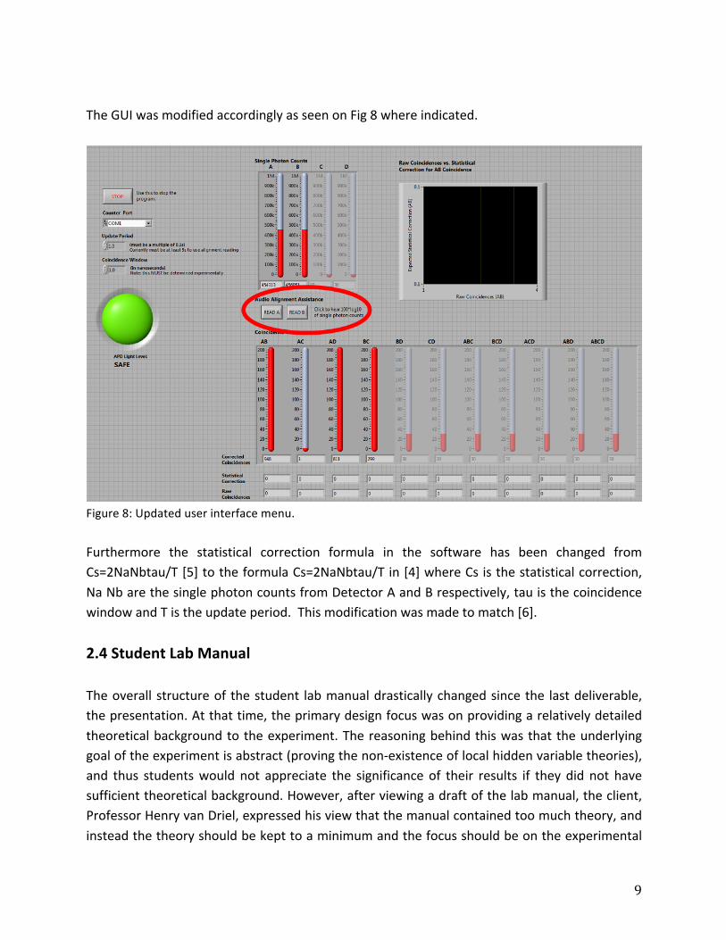
The GUI was modified accordingly as seen on Fig 8 where indicated.
Figure 8: Updated user interface menu. Furthermore the statistical correction formula in the software has been changed from Cs=2NaNbtau/T [5] to the formula Cs=2NaNbtau/T in [4] where Cs is the statistical correction, Na Nb are the single photon counts from Detector A and B respectively, tau is the coincidence window and T is the update period. This modification was made to match [6]. 2.4 Student Lab Manual The overall structure of the student lab manual drastically changed since the last deliverable, the presentation. At that time, the primary design focus was on providing a relatively detailed theoretical background to the experiment. The reasoning behind this was that the underlying goal of the experiment is abstract (proving the non-‐existence of local hidden variable theories), and thus students would not appreciate the significance of their results if they did not have sufficient theoretical background. However, after viewing a draft of the lab manual, the client, Professor Henry van Driel, expressed his view that the manual contained too much theory, and instead the theory should be kept to a minimum and the focus should be on the experimental

10
components. He pointed out that students would be likely be uninterested in the experiment if the lab manual was too long and difficult to read. Having agreed with the feedback given by the client, the lab manual was redesigned take these suggestions into account. A short introduction to the experiment is first provided to engage the students’ interests and give an overall picture. The theoretical background throughout the document is kept at a minimum. To account for students with an interest in understanding the background material, reference is made to a scientific paper that outlines the same experiment that the student will be performing. This paper provides all the necessary background material, and will be accessible to students with a basic background in quantum mechanics (preferably at a third-‐year level). While the client suggested that the theory written in the previous draft be included in an appendix to the manual, we have decided that this information may be redundant given the new design, and the access students have to the paper mentioned. Students completing the experiment who read both the manual and the paper should have a thorough appreciation for the implications and physics behind the experiment. Furthermore, less advanced students will still be able to complete the lab and gain some insight without reading the paper. Another design decision that the client suggested we alter was the use of pictures in the lab manual. Previously, we intended to include pictures for every component of the apparatus separately. The client pointed out that this was somewhat unnecessary, and in fact it would be providing too much information to the students. Instead, he recommended we include only pictures of the overall apparatus and label each component in the diagram. This change has been made in the new document. While some major components of the lab manual design have changed in response to the client’s feedback, some design decisions have been preserved from the previous draft. In particular, the general approach to maintaining a balance between clarity and open-‐endedness in the manual has not changed. A minimal theoretical explanation of how the experiment is to be completed is first provided, followed by a point-‐form list of instructions that are kept relatively open-‐ended (with the exception of the alignment stage, which requires more specific direction due to its difficulty). The aim of this design choice is to provide students with a general picture of how to complete the experiment so that the point-‐form instructions are not required to be as detailed and constraining. Another design choice that has been kept from the old draft is the ‘safety reminders box’ immediately preceding the procedures section of the manual. This component was a requirement expressed by Professor David Bailey.

11
3. Source Materials 3.1 Parts list
○ Detectors ○ Collectors ○ Focusing lens (new) ○ HWP ○ QWP (new) ○ Mirrors (new) ○ BBO ○ Polarizers ○ Pump laser ○ Rails ○ Beam stop (new) ○ Mounts ○ Filters ○ Collimating tube ○ Multimode fibers ○ Irises ○ Alignment laser ○ Laser pointer ○ Spanner wrench
3.2 Final Deliverables Package Contents
● Student Lab Manual with alignment guide ● TA Manual
3.3 Files In addition to the files listed in the previous development report the following files will be relevant for this experiment:
File Location Audience Purpose
SolidWorks file Sent through email Developers, laboratory technicians
Submit to machine shop to replace foam core prototype with a

12
plastic version
Final report Sent through email Developers
Lab manual Sent through email Students The main document to guide the students through the experiment
TA manual Sent through email Teaching assistants, professors
Extra information provided to the teaching team in case students require assistance
Alignment manual Appended to the lab manual
Students, Teaching assistants, Technicians
Flowchart to guide the students through the alignment process in a systematic way
Demo.xlsx MP 244 computer C://Quantum
Teaching assistants Sample data, data analysis, and measurement process
Detection.llb Installed in MP 244 computer C://Quantum
Developers Modified LabVIEW software and GUI
Detection_2012.llb MP 244 computer C://Quantum
Developers Unmodified LabVIEW software and GUI
Reader.vi Installed in MP 244 computer C://Quantum
Developers LabVIEW audio alignment assistance subfunction
Audio files Installed in MP 244 computer C://Quantum/audio
Developers Audio tracks for number reading in audio alignment assistance
IE develop labbook MP 244 Developers Lab notebook documenting development work since Jan 2013

13
4. Future Work 4.1 Laboratory Setup Numerous amendments could be explored that could increase the purity and consistency of the Bell state. We suspect that the pump laser polarization (with respect to earth) may fluctuate nontrivially over time. The experiment is extremely sensitive to polarization orientation, at times sensitive to half degree differences. To rectify this, the consequences of replacement the half wave plate (which rotates polarization) to a linear polarizer oriented 45 degrees with respect to earth should be investigated. This essentially forces the correct photon polarization to be modified by the QWP and subsequently entangled by the BBO crystal. This change would come at the expense of reduced transmission since much of the original pump laser light would be absorbed by the polarizer. Also the transmission may fluctuate, since the amount of light that transmits is a function of fluctuating pump laser polarization. Thus the effect of this change would be to trade fluctuation in polarization to fluctuation in transmission. As mentioned, mechanical vibrations are a leading cause of state drifting in this design. In the future, installing vibration pads beneath the optical table will assist in the optical isolation effort. A viable product to solve this problem is available at [7] which has been used under optical tables in other Advanced Physics Laboratory rooms. 4.2 LabVIEW Software Software and GUI modifications were not primary priorities at this time, however in the duration of this development project, we found that several modifications to the LabVIEW software would enhance the behaviour and interaction of students with the lab. These include:
1. Recalculation of the APD warning level: Currently the warning level on the GUI only considers the absolute single photon counts to determine photodetector safety regardless of the update period entered in the software. However the APDs meter saturates at a rate (1,000,000 photons/s) [6] which requires consideration of update period. It has been demonstrated that student behaviour is altered by the presence warning level so it is important that the warning signal does not constrain students unnecessarily.
2. Audio alignment assistance modifications

14
a. Maximal corrected coincidence counts are imperative to obtaining a discernable Bell state. As such an additional button should be added to read the corrected coincidence counts.
b. The placement of the buttons should be redesigned such that a student does not have to check the monitor for pointer placement. Furthermore, buttons for detector C and D counts have not been implemented but may be necessary for other entanglement experiments
c. The method currently used to discern is increase or decrease in counts reads numbers. In the future, it would be beneficial to hear more continuous feedback, for example, hearing a tone frequency as a function of photon counts.
Please refer to the final design documentation in 2012 [6] for further improvements on software modularity and performance. 4.3 Alignment Laser Module The fibers connecting the collectors to the APD detectors are fragile and should not under any circumstance be left unprotected. That said, the laser pointer used as an alignment laser must be secured such that light is coupled into the fiber without having the fiber touch the laser pointer. From Fig. 9, it can be observed that is it currently held in place by tape. To prevent students from damaging the fiber during alignment, a module should be designed to secure the laser pointer and fiber for alignment.
Figure 9: photograph of current laser alignment module.

15
4.4 Extension to other quantum entanglement experiments As discussed in the Design Proposal [1], our setup can easily be extended to perform experiments other than just the Bell’s Inequalities experiment. Since the generation of entangled photons is done separately from the manipulation of these photons, the same generation and detection modules can be adjusted to accommodate other experiments such as Hardy’s experiment, Granger’s experiment, quantum eraser and single photon interference experiments. See [1] for further information and resources regarding these experiments.
5. Bill of Materials
Item Unit cost (CAD) Vendor
Foam core sheets (x2) 12 Toose Art Supply Store
Acrylic sheet (x1) 14.07 Home Depot
HWP mounting bolts 10 Home Hardware
QWP (x1) 249 Newlight Photonics
Lenses (x2) 30 Thorlabs
Cage rotation mount (x1) 88 Thorlabs
HeNe laser adapter (x1) 50 Thorlabs
Kinematic mount (x2) 89 Thorlabs

16
6. References [1] D. Lo, S. Strimas-‐Mackey, T. Onodera, and S. Sharma "ESC471H1 F Capstone Design: Conceptual Design -‐ Bell's Inequalities Experiment." ESC471 Capstone Design, University of Toronto (2013) [2] D. Lo, S. Strimas-‐Mackey, T. Onodera, and S. Sharma "ESC471H1 F Capstone Design: Proposal -‐ Bell's Inequalities Experiment." ESC471 Capstone Design, University of Toronto (2013) [3] J. Bateman, J. Nicholls, Z. Zhu “Parts Inventory” ESC471 Capstone Design, University of Toronto (2012) [4] D. Dehlinger, and M. W. Mitchell. "Entangled photon apparatus for the undergraduate laboratory." American Journal of Physics 70 (2002) [5] J. Bateman, J. Nicholls, Z. Zhu “Final Report” ESC471 Capstone Design, University of Toronto (2012) [6] D. Dehlinger and M. W. Mitchell. “Entangled photons, nonlocality, and Bell inequalities in the undergraduate laboratory” Am. J. Phys. 70, 903 (2002). [7] ThorLabs product webpage, part number SB12A. Web. 17 Dec. 2013
URL: http://www.thorlabs.com/thorproduct.cfm?partnumber=SB12A

17
7. Appendix
12/20/13 Gmail - Quantum Entanglement experiment laser enclosure
https://mail.google.com/mail/u/0/?ui=2&ik=0395741723&view=pt&q=sandu.sonoc%40utoronto.ca&psize=20&pmr=100&pdr=50&search=apps&msg=142d84b69… 1/1
Shashwat Sharma <[email protected]>
Quantum Entanglement experiment laser enclosure
Sandu Sonoc <[email protected]> Mon, Dec 9, 2013 at 11:58 AMTo: Shashwat Sharma <[email protected]>
Hi Shashwat,
To use the experimental setting by persons without laser safety training the following conditions must be fulfilledfirst:
1. Verify that the box and the optic elements are well fixed on the table (they cannot be moved by mistake –you need a tool to move them)
2. The main beam is blocked by the beam stop inside the box
3. The interlock is connected, and working
If these conditions are fulfilled the experiment can be performed without laser safety training and without lasersafety goggles.
Best regards,
Sandu Sonoc, PhD, P.Eng.Senior Radiation Safety Officer, Laser Safety OfficerOffice of Environmental Health and Safety215 Huron St, Room 709FToronto, Ontario M5S 1A2Phone: 416-978-2028, Fax 416-971-1361
This email may contain information that is private, confidential, and / or legally privileged. It is intendedfor the sole use of the intended recipient(s). You must not distribute to others or allow others to reviewthis message without the specific consent of the sender. If you are not an intended recipient, youmust not review, copy or distribute this email, and you are asked to immediately notify the sender anddelete this email.
From: Shashwat Sharma [mailto:[email protected]] Sent: Monday, December 09, 2013 1:02 AM
[Quoted text hidden]
[Quoted text hidden]