Embed Size (px)
Citation preview
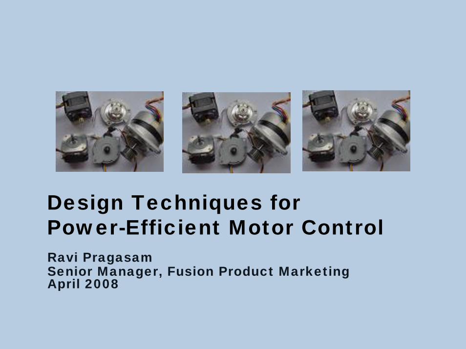
Ravi Pragasam Senior Manager, Fusion Product Marketing April 2008
Design Techniques for Power-Efficient Motor Control
Feb 29 08
Need for power-efficient motor controlImproving motor efficiencies using Programmable System Chips
Integrated Pulse Width Modulation Power efficiency schemes
Quadrature encoder interfaceLoad matching and variable speed controlSlip control
Summary
Design Techniques for Power-Efficient Motor Control
Agenda

Electronic motors have become increasingly ubiquitousWith this growth comes increasing requirements for improved performance, efficiency and flexibilityElectric motors use half of all US electricity consumed
In 2005, US consumed 4,055 billion KWh of electrical power More than 50% of this was consumed by electric motors
Design Techniques for Power-Efficient Motor Control Feb 29 08
Motor Control Power Consumption Profile

High cost of control and power electronics has been a major barrier to deployment of intelligent power management solutions Implemented broadly, efficient electronic motor control could result in savings of as much as 15% of the power consumed in the U.S.
An annual reduction of as much as 300 billion kWh and $15 billion saved
Feb 29 08Design Techniques for Power-Efficient Motor Control
The Need for Power-efficient Motor Control
Feb 29 08
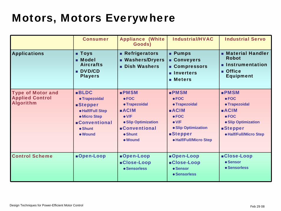
Consumer Appliance (White Goods)
Industrial/HVAC Industrial Servo
Applications ToysModel AircraftsDVD/CD Players
RefrigeratorsWashers/DryersDish Washers
PumpsConveyersCompressorsInvertersMeters
Material Handler RobotInstrumentationOffice Equipment
Type of Motor and Applied Control Algorithm
BLDCTrapezoidal
StepperHalf/Full StepMicro Step
ConventionalShuntWound
PMSMFOCTrapezoidal
ACIMV/FSlip Optimization
ConventionalShuntWound
PMSMFOCTrapezoidal
ACIMFOCV/FSlip Optimization
StepperHalf/Full/Micro Step
PMSMFOCTrapezoidal
ACIMFOCSlip Optimization
StepperHalf/Full/Micro Step
Control Scheme Open-Loop Open-LoopClose-Loop
Sensorless
Open-LoopClose-Loop
SensorSensorless
Close-LoopSensorSensorless
Design Techniques for Power-Efficient Motor Control
Motors, Motors Everywhere

64/29/2008Feb 29 08Feb 29 08
Need for power-efficient motor controlImproving motor efficiencies using Programmable System Chips
Integrated Pulse Width Modulation Power-efficiency schemes
Quadrature encoder interfaceLoad matching and variable speed controlSlip control
Summary
Design Techniques for Power-Efficient Motor Control
Agenda

Feb 29 08Design Techniques for Power-Efficient Motor Control
Traditional Motor Control Implementation
84/29/2008
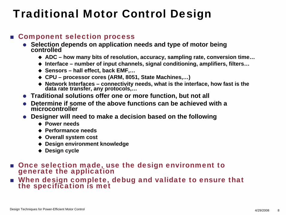
Component selection processSelection depends on application needs and type of motor being controlled
ADC – how many bits of resolution, accuracy, sampling rate, conversion time…Interface – number of input channels, signal conditioning, amplifiers, filters…Sensors – hall effect, back EMF,…CPU – processor cores (ARM, 8051, State Machines,…)Network Interfaces – connectivity needs, what is the interface, how fast is the data rate transfer, any protocols,…
Traditional solutions offer one or more function, but not allDetermine if some of the above functions can be achieved with a microcontroller Designer will need to make a decision based on the following
Power needsPerformance needsOverall system costDesign environment knowledge Design cycle
Once selection made, use the design environment to generate the applicationWhen design complete, debug and validate to ensure that the specification is met
Design Techniques for Power-Efficient Motor Control
Traditional Motor Control Design
94/29/2008
Component selection process Ideal solution will integrate several functions into oneSeveral benefits can be obtained with an integrated solution
Lower overall powerLower system costLess design complexityBetter signal integritySingle platform that can be scaled
Optional functions can be included based on needsPlatform needs to be flexible to accommodate different needs
Use design environment to generate the applicationWhen design complete, debug and validate to ensure that the specification is met
Design Techniques for Power-Efficient Motor Control
Changing Motor Control Design

Incorporate analog functions, embedded flash memory and FPGA fabric in a single chipFlexible platform for scalabilityOffers benefits of monolithic design environment
Design Techniques for Power-Efficient Motor Control
Programmable System Chips - PSCs

114/29/2008Feb 29 08
GPIO
FLASH Memory
JTAG Port
FPGA Fabric(incl. SRAM, CCC/PLL, IO)
Xtal OSC,RC OSC,
RTC, Vreg
PSC Offers Analog IntegrationSuccessive Approximation Register (SAR) ADC
Up to 12 bit or 600 KspsBetter than 1% total channel accuracy with calibrationInternal reference voltage
Built in sample and holdIncreases accuracy of dynamic signals
Analog I/O± 12 V TolerantUp to 30 channels inputCurrent monitor block
2 mV resolutionTemperature monitor block
+ 3o C accuracy+ 5O C Offset
MOSFET Gate driver outputProgrammable drive strengthP and N channel devices
AnalogInputs
MOSFETOutputs
A/DAna
Mux
Ana
Mux
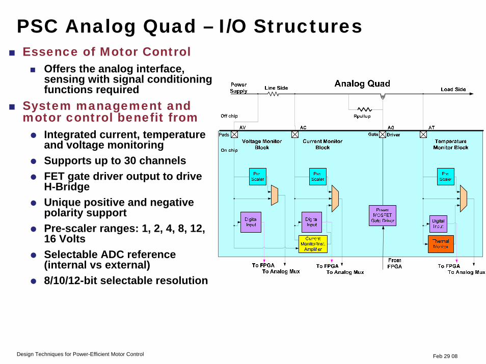
Essence of Motor Control Offers the analog interface, sensing with signal conditioning functions required
System management and motor control benefit from
Integrated current, temperature and voltage monitoring Supports up to 30 channelsFET gate driver output to drive H-BridgeUnique positive and negative polarity support Pre-scaler ranges: 1, 2, 4, 8, 12, 16 VoltsSelectable ADC reference (internal vs external) 8/10/12-bit selectable resolution
Feb 29 08Design Techniques for Power-Efficient Motor Control
PSC Analog Quad – I/O Structures

134/29/2008Feb 29 08
Methodology For Flexible Functionality
Graphical productivity toolsADC sampling
Digital low-pass filtering
Threshold comparisons
State filtering
Analog input
High current output
Flash memory access
Automatically connects FPGA, flash and analog block with required functions

Feb 29 08Design Techniques for Power-Efficient Motor Control
Using PSCs for Motor Control
Programmable System Chip
PSC
PSC can integrate multiple functions into a single platform
Take analog inputs from motor with the analog interface and ADCLeverage CPU for processing and control (Cortex-M1, 8051)Utilize flash memory to store the program and embedded SRAM blocks to store dataUse clock circuitry for generating signals needed for control (RC Oscillator)Interface to external components with network and peripheral interface Utilize soft PWM cores to generate current or voltage for gate drivers
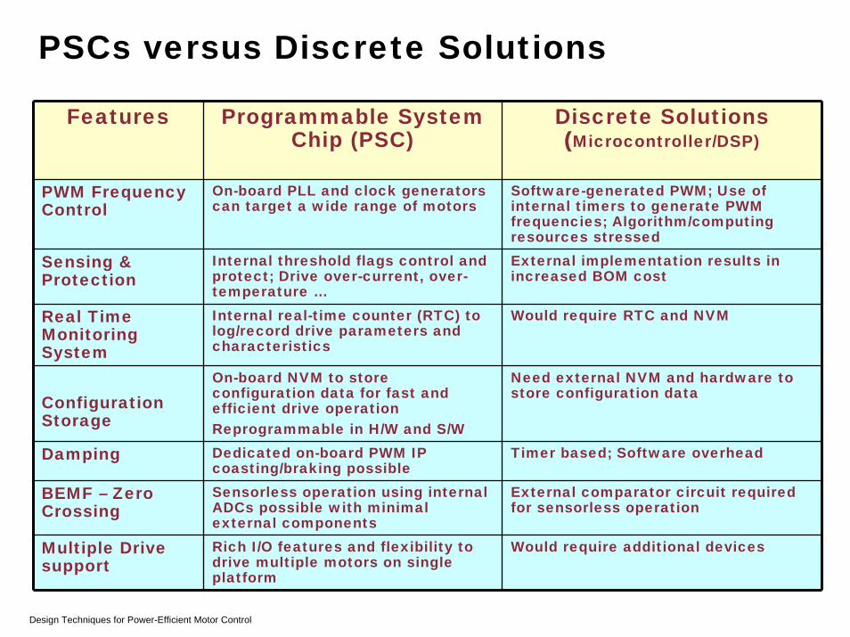
Features Programmable System Chip (PSC)
Discrete Solutions(Microcontroller/DSP)
PWM Frequency Control
On-board PLL and clock generators can target a wide range of motors
Software-generated PWM; Use of internal timers to generate PWM frequencies; Algorithm/computing resources stressed
Sensing & Protection
Internal threshold flags control and protect; Drive over-current, over-temperature …
External implementation results in increased BOM cost
Real Time Monitoring System
Internal real-time counter (RTC) to log/record drive parameters and characteristics
Would require RTC and NVM
Configuration Storage
On-board NVM to store configuration data for fast and efficient drive operationReprogrammable in H/W and S/W
Need external NVM and hardware to store configuration data
Damping Dedicated on-board PWM IP coasting/braking possible
Timer based; Software overhead
BEMF – Zero Crossing
Sensorless operation using internal ADCs possible with minimal external components
External comparator circuit required for sensorless operation
Multiple Drive support
Rich I/O features and flexibility to drive multiple motors on single platform
Would require additional devices
Design Techniques for Power-Efficient Motor Control
PSCs versus Discrete Solutions

PWM control works by switching the power supplied to the motor on and off very rapidlyDC voltage is converted to a square-wave signal, alternating between fully on and zero, giving the motor a series of power "kicks"If switching frequency is high enough, the motor runs at steady speed due to fly-wheel momentumBy adjusting the signal’s duty cycle, the average power and motor speed can varyUsed to implement closed loop control of motorsCan be implemented by discrete components
Feb 29 08Design Techniques for Power-Efficient Motor Control
Pulse Width Modulation (PWM) - Basics
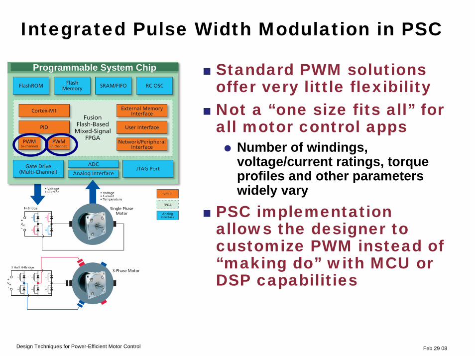
Standard PWM solutions offer very little flexibilityNot a “one size fits all” for all motor control apps
Number of windings, voltage/current ratings, torque profiles and other parameters widely vary
PSC implementation allows the designer to customize PWM instead of “making do” with MCU or DSP capabilities
Programmable System Chip
Integrated Pulse Width Modulation in PSC
Feb 29 08Design Techniques for Power-Efficient Motor Control
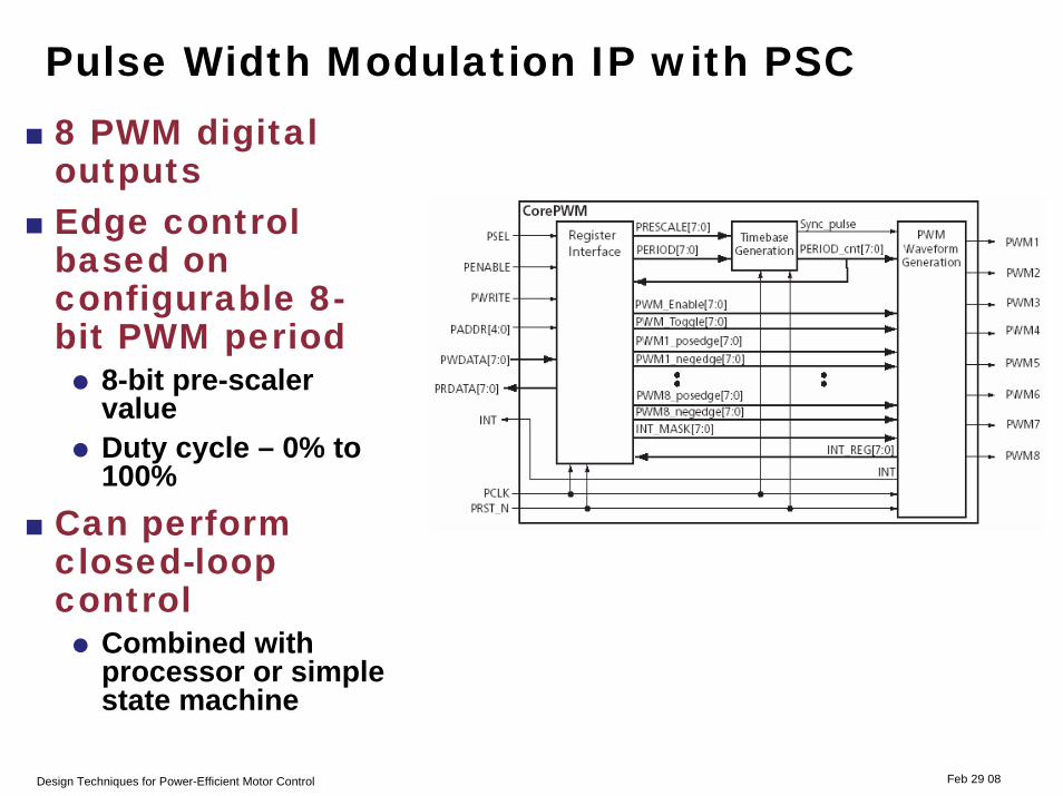
Feb 29 08
8 PWM digital outputsEdge control based on configurable 8-bit PWM period
8-bit pre-scaler valueDuty cycle – 0% to 100%
Can perform closed-loop control
Combined with processor or simple state machine
Design Techniques for Power-Efficient Motor Control
Pulse Width Modulation IP with PSC

Feb 29 08
Allows designer to define parameters based on need
Number of outputsNegative or positive edge of each output Interrupt maskEnable PWMDuty cycle
Effectively provides power-sensitive motor control based on environmental need
Design Techniques for Power-Efficient Motor Control
PWM Implementation Methodology
204/29/2008Feb 29 08
Need for power-efficient motor controlImproving motor efficiencies using Programmable System Chips
Integrated Pulse Width ModulationPower-efficiency schemes
Quadrature encoder interfaceLoad matching and variable speed controlSlip control
Summary
Design Techniques for Power-Efficient Motor Control
Agenda
214/29/2008
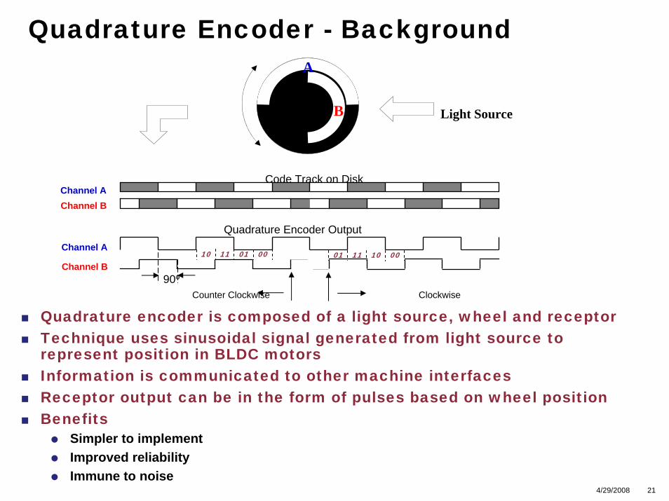
Quadrature Encoder - Background
Light Source
00011110
Code Track on DiskChannel AChannel B
Channel A
Channel B
Quadrature Encoder Output
90o
Counter Clockwise Clockwise
00101101
A
B
Quadrature encoder is composed of a light source, wheel and receptorTechnique uses sinusoidal signal generated from light source to represent position in BLDC motorsInformation is communicated to other machine interfacesReceptor output can be in the form of pulses based on wheel positionBenefits
Simpler to implement Improved reliabilityImmune to noise
Most high-precision motors, like the servo-type stepper motors, support quadrature-encoder interfaces Control system must provide quadrature-encoder interface logic to determine accurate speed, position and acceleration of the motion rotorsWith a PSC, accuracy and dynamic speed can be adjusted, depending on the characteristics of the motor
FPGA
Index
Filter
Filter
QuadratureDecoder
Up/DownCounter
DIR(U/D)
Reset
CNT
ChA
ChB
CCC/PLL
FPGA LogicFusion Block
Filter
QEB
QEA
Feb 29 08Design Techniques for Power-Efficient Motor Control
Implementing Quadrature Encoder Interface
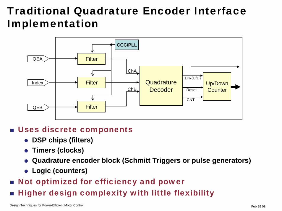
Uses discrete componentsDSP chips (filters) Timers (clocks)Quadrature encoder block (Schmitt Triggers or pulse generators) Logic (counters)
Not optimized for efficiency and powerHigher design complexity with little flexibility
FPGA
Index
Filter
Filter
QuadratureDecoder
Up/DownCounter
DIR(U/D)
Reset
CNT
ChA
ChB
CCC/PLL
FPGA LogicFusion Block
Filter
QEB
QEA
Feb 29 08Design Techniques for Power-Efficient Motor Control
Traditional Quadrature Encoder Interface Implementation
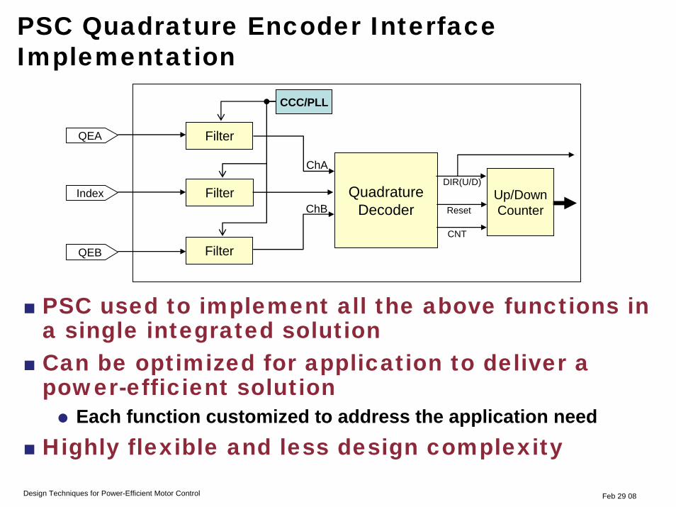
PSC used to implement all the above functions in a single integrated solutionCan be optimized for application to deliver a power-efficient solution
Each function customized to address the application needHighly flexible and less design complexity
Feb 29 08Design Techniques for Power-Efficient Motor Control
PSC Quadrature Encoder Interface Implementation
FPGA
Index
Filter
Filter
QuadratureDecoder
Up/DownCounter
DIR(U/D)
Reset
CNT
ChA
ChB
CCC/PLL
FPGA LogicFusion Block
Filter
QEB
QEA

For applications that need to be operated at a constant speed, intelligent load matching is a great way to deliver an efficient solution
Load sensed and matched with the proper input power, maximizing efficiency and minimizing power consumption and operating costs
Variable-Frequency Drives (VFD)For low-cost drives suitable for applications with known loading, VFDsused to vary the motor's rotational speed to match current load condition
Vector Control Schemes (Field oriented)Use real world feedback (speed or torque) to adjust to load variationsDeals with varying operating conditions and allows responsive and accurate speed control with a changing load Offers optimum efficiency even during motor transitionTraditional solutions use microcontrollers and DSPs to implement the closed loop control for speed and torqueUsing PSCs allow a single device to be used to control a range of motor types, including permanent-magnet AC and brushless DC motors
Feb 29 08Design Techniques for Power-Efficient Motor Control
Load Matching and Variable Speed Control
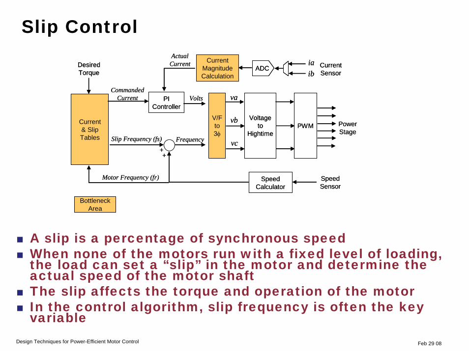
A slip is a percentage of synchronous speedWhen none of the motors run with a fixed level of loading, the load can set a “slip” in the motor and determine the actual speed of the motor shaftThe slip affects the torque and operation of the motor In the control algorithm, slip frequency is often the key variable
Voltage to
HightimePWM
SpeedCalculator
PI Controller
Motor Frequency (fr)
Frequency
Current & Slip Tables
Volts
Slip Frequency (fs)
++
Current Sensor
ADCib
Actual CurrentDesired
Torqueia
SpeedSensor
V/F to 3φ
va
vb
vc
CurrentMagnitude Calculation
Commanded Current
Power Stage
Bottleneck Area
Voltage to
HightimePWM
SpeedCalculator
PI Controller
Motor Frequency (fr)
Frequency
Current & Slip Tables
Volts
Slip Frequency (fs)
++
Current Sensor
ADCib
Actual CurrentDesired
Torqueia
SpeedSensor
V/F to 3φ
va
vb
vc
CurrentMagnitude Calculation
Commanded Current
Power Stage
Bottleneck Area
Feb 29 08Design Techniques for Power-Efficient Motor Control
Slip Control
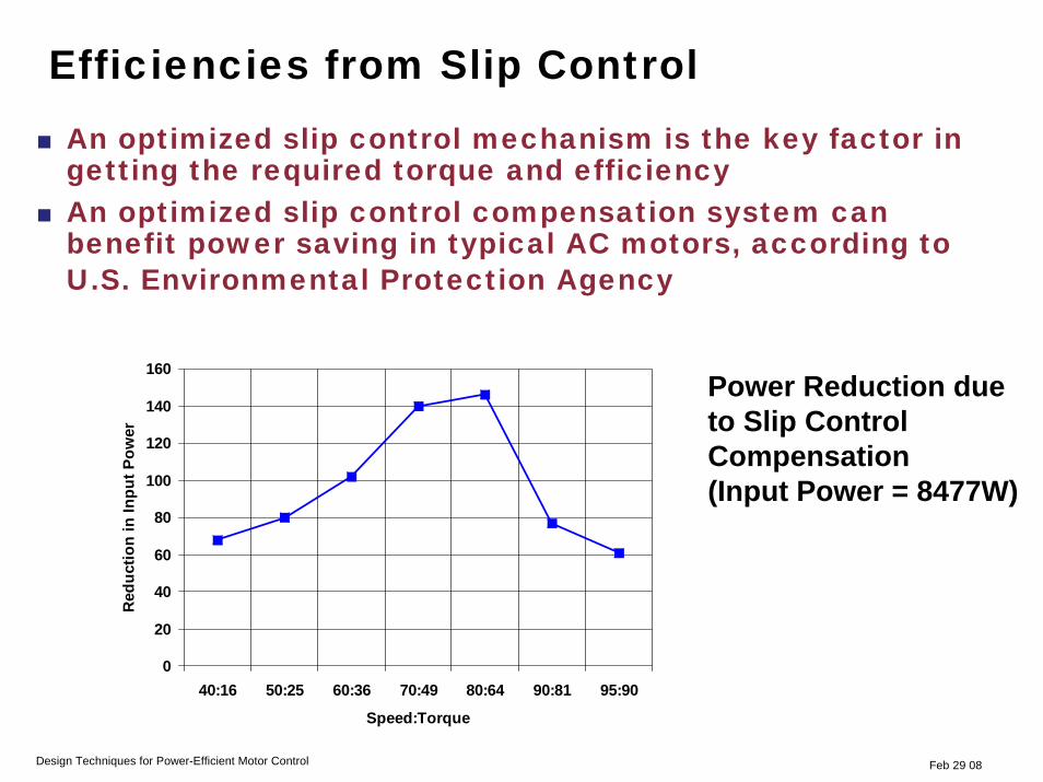
An optimized slip control mechanism is the key factor in getting the required torque and efficiencyAn optimized slip control compensation system can benefit power saving in typical AC motors, according to U.S. Environmental Protection Agency
0
20
40
60
80
100
120
140
160
40:16 50:25 60:36 70:49 80:64 90:81 95:90
Speed:Torque
Red
uctio
n in
Inpu
t Pow
er
Power Reduction due to Slip Control Compensation (Input Power = 8477W)
Feb 29 08Design Techniques for Power-Efficient Motor Control
Efficiencies from Slip Control
Feb 29 08
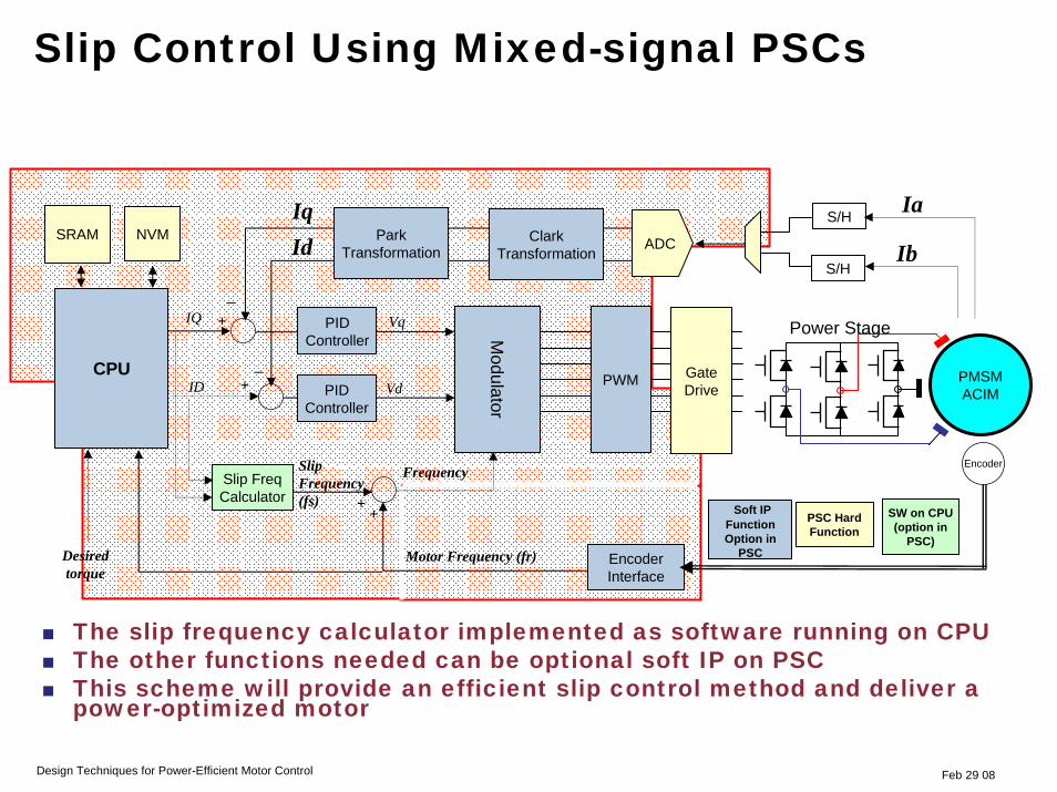
PWM Gate Drive
Power Stage
PMSMACIM
Encoder
Encoder Interface
PID Controller
Motor Frequency (fr)
Frequency
CPU
Slip Frequency (fs)
++
Ib
+
Desired torque
NVM
Ia
S/H
IqSRAM
+
_
Id
_Vd
Slip Freq Calculator
Vq
PID Controller
IQ
ID
ParkTransformation
ClarkTransformation
S/H
ADC
Modulator
Soft IP Function Option in
PSC
PSC Hard Function
SW on CPU (option in
PSC)
Design Techniques for Power-Efficient Motor Control
The slip frequency calculator implemented as software running on CPU The other functions needed can be optional soft IP on PSCThis scheme will provide an efficient slip control method and deliver a power-optimized motor
Slip Control Using Mixed-signal PSCs

294/29/2008Feb 29 08Feb 29 08
Need for power-efficient motor controlImproving motor efficiencies usingProgrammable System Chips
Integrated Pulse Width ModulationPower-efficiency schemes
Quadrature encoder interfaceLoad matching and variable speed controlSlip control
Summary
Design Techniques for Power-Efficient Motor Control
Agenda
Feb 29 08
Increasing demand for energy savings and lower power puts pressure on designers to use more efficient motorsTraditional solutions may not offer the best solution for efficient motorsHighly integrated, flexible PSCs allow designers to implement the most efficient design for their application and also use the same device across motor applications Implemented broadly, electronic motor control could result in savings of as much as 15% of the power used in the U.S.
Design Techniques for Power-Efficient Motor Control
Summary