Embed Size (px)
Citation preview
~\\~~\ esa~ - = II:: = 18111111l1li= III:: D
ESA STR-241
September 1997
An Inspection ofSpacelab Hardware
B. D. Dunn and R. StanyonEuropean Space Research and Technology CentreNoordwijk, The Netherlands
European Spate AgentyAgente spatia/e europeenne

SA STR-241
eptember 1997
Authors:
Published by:
Editor:
Price:
ISBN No.
Copyright:
Printed in:
11
A report onvisual inspection of Spacelab hardware
at NASA's Kennedy Space Center
24-261h February 1997
ESA STR-241- 'Spacelab Hardware Inspection'
B.D.Dunn and R.Stanyon
ESA Publications Division
ESTEC, Noordwijk, The Netherlands
R.A Harris
Dfl.35
92-9092-329-6@ 1997 The European Space Agency
The Netherlands

Summary
Spacelab has been one of the European Space Agency's most important long-termprojects and is a major contribution to the US Space Shuttle programme. All of itsstorage, launch and mission activities are controlled by NASA. The hardware wasmanufactured in Europe and qualified by ESA more than 15 years ago. Two ESA staffmembers who had participated in the Spacelab development activities during the1970's and 80's have now re-inspected much of the hardware (stored at NASA-KSC)and formally discussed materials and processes problems with long-term NASA andMDAC personnel. This report summarises their finding and contains a pictorial recordof inspected items which should be of interest to forthcoming projects such as theInternational Space Station.
III

This page deliberately left blank
IV

Contents
Abbreviations ... ... ... ... ... ... ... ... ... ... vii
I . In troducti 0n I
2. 0 bj ecti ve I
3. Method I
4. Fi n di n gs .. .. .. .. .. .. .. . .. .. .. . .. .. . . .. .. . .. .. .. .. . .. .. .. .. . .. . .. . .. .. .. . .. . . .. . .. . .. . .. . .. . .. . .. . .. . .. .. .. . .. .. . .. .. .. .. .. .. . .. .. . .. .. 3
4.1. Surface Protection Treatments for AA 2219 3
4.2. Water Condensation 3
4.3. Painted Surfaces and Optical Properties II
4.4. Mechanical Damage to Thermal Protection Systems II
4.5. In te rf ace Pro b Ie m s .. . .. . .. .. .. .. .. .. .. . .. .. .. .. . .. .. .. . .. . .. .. .. .. .. .. . .. . .. . .. . .. . .. .. . .. .. .. . .. .. .. .. .. .. . .. .. .. .. .. I I
4.6 Limited Life Items and Physical Degradation 17
4.7. Examination of MLI Hold-down Button 25
4.8. Space Station International Standard Payload Racks (ISPR) 33
5. Acknowledgements 33
References 35
Annex I Discussion Topics 37
Annex 2 List of Attendeesat Discussion on Spacelab Processing 38
Annex 3 Spacelab Hardware Assignments 39
Annex 4 STS - Orbiter - Payload Assignments 42
Index 43
v

This page deliberately left blank
VI

AAC/DCHXCOFDDUEMEPDBEVAFOPHDRRIMLIPSISPRKSCLEOLRULMSMDACMGSEMLIMMUMPRVMSFCMSLO&COFTPCBPTFERTVSCCSLSSPDBSTSTIG
Abbreviations
Aluminium alloy
Development and production phases of a projectCondensate Heat ExchangerColumbus Orbital FacilityData Display UnitEngineering ModelElectrical Power Distribution BoxExtra Vehicular ActivityFollow On ProductionHigh Data Rate RecorderInternational Microgravity LaboratoryInstrument Pointing SystemInternational Standard Payload rackKennedy Space CenterLow Earth OrbitLine Replacement UnitLife and Microgravity SciencesMcDonnell Douglas Astronautics Company (until December 1988)Mechanical Ground Support EquipmentMulti-layer InsulationMass Memory UnitModule Pressure Relief ValveMarshall Space Flight CenterMaterials Science LaboratoryOperations and CheckoutOrbital Flight TestPower Control BoxPol ytetrafluoroethy leneRoom Temperature VulcanisingStress Corrosion Crack (testing)Spacelab Life SciencesSystem Power Distribution BoxSpace Transportation SystemTungsten Inert Gas
VII

c.. .... ~- .
<::..,
.:J
~
". dr.
~
""
,...''"
~.~. .-
'f! ~:,'I
/.. .
{tfJ .
A
.'. ,'.. .'
';;?'-;..~',
t
"
.'~,
' ',..C.J /. \,
.'-.'-~
..,."
,~\~ I'.\ - .
i
"';', I. .
~', ... '~ 'c.,"""'-
~
\
'~... l 1i"', .
.
f,.':~. ..
\
f"'..'.
.
viii
~........:::
..c:1J)Q.I~~Q.,
r.rJQ.I
..c:....
.....0
"0'0..c:Q.I
..c:....:::....
I..c~
~~~Q.,
r.rJ

1. Introduction
Spacelab hardware was manufactured in the late 1970's and early 1980's, with design requirements ofa lifetime of at least 10 years and 50 missions of approximately 7 days duration. It is now more than15 years since the first hardware was delivered to the NASA-Kennedy Space Center (KSC) for theOrbital Flight Test (OFT) missions which utilised the Engineering Model (EM) Pallets EM 02 andEM 03. The first flight version of Spacelab was delivered on 5th February 1982, its maiden flightbeing in November 1983. Later deliveries of the IPS (Instrument Pointing System), the Igloo,Spacelab 2 Phase C/O and Follow on Production (FOP) systems and spares completed the inventoryof the ESA-supplied hardware by 1985.
The present condition of the Spacelab hardware is a significant source of information for checking theadequacy of the qualification procedures and processes that were used to achieve the 10 year liferequirement. The recent visit to inspect the various Spacelab hardware items visually and to discusspossible materials and process problems, with long-term NASA personnel who had been associatedwith the day-to-day use and operation of the hardware, proved to be extremely useful. It also helped tojustify the choice of the same materials and processes for the construction of the Columbus OrbitalFacility (COF) as well as for other future ESA projects. NASA-KSC engineers welcomed theproposal that ESA representatives should visit their facilities and made the Spacelab hardware,located in the Operations and Checkout (O&C) Building, available for viewing and inspection.
2. Objective
In addition to confirming the efficacy of the qualification, the objective of the inspection was toidentify problems which had been experienced and which can be fed back into future ESA tasks, toimprove performance. The hardware characteristics which were considered significant were:corrosion resistance, thermal protection, physical degradation, ageing and contamination.
Annex 1 lists the characteristics and topics discussed during the visit to KSC. The ESA participants, aproject Quality Engineer and a Metallurgist, are familiar with the early Spacelab developments inEurope.
3. Method
NASA, with the support of its Spacelab processing contractor McDonnell Douglas AstronauticsCompany (MDAC), provided a forum of engineers and technicians (see Annex 2) with experiencecovering the lifetime of the Spacelab utilisation. Each item in Annex 1 was discussed in detail andcomments, observations and where warranted constructive criticism, were made in very open andproductive meetings. An overview of the various Spacelab hardware assignments and the STS-Orbiterassignments is given in Annexes 3 and 4.
The common sentiment of the NASA and MDAC personnel was that the Spacelab hardware hadproved to be of high quality and reliability and that very few significant problems had beenexperienced since the anomalies on the Spacelab 1 and Spacelab 2 missions and the subsequentNASA replacement of the ESA-supplied computers and Data Display Units (DDU's) with moremodem equipment. Such information was very encouraging and welcome, but as the main objectivewas to identify lessons that may be learned from the 17 years of Spacelab processing, emphasis wasplaced on negative aspects of performance.
The discussions were followed by extensive viewing of the hardware and by inspection andphotography of items considered to be of interest.

Fig. 1: Partial construction of a Spacelab module in Europe during 1979.TIC Welding processes were used to weld panels and rings.
Base material is AA 2219-T851 (plates and forged rings).
Filler metal is AA 2319.
2

4. Findings
4.1. Surface Protection Treatments for AA 2219
4.1.1. Brief History
The selection of a main structural alloy for the European Space Agency (ESA) Spacelab project wasmade in the mid-1970's. The choice of aluminium alloy 2219 was based on the need for a materialhaving an optimum combination of mechanical strength, fracture toughness and resistance to generalcorrosion and stress-corrosion cracking. An extensive programme for the qualification of the Spacelabsurface protection treatments was undertaken on sheet, plate and forged rings that had been bothchemically milled and TIG welded. The qualification test samples were made with the processes,heat-treatments and finishes that would be later used to fabricate the first Spacelab module (seeFigures 1 to 3).
The waffle structures and general flat surfaces were chromic acid anodised. The TIG welds wereground, polished and brush Alodined. Large numbers of anodised waffle structures and welded platesfinished with Alodine 1200 were subjected to salt spray testing for up to 4 weeks (672 hours). It hadbeen proposed that a two-week (336 hours) exposure would represent the required 10 year Spacelablife. Whereas the anodised samples exhibited a good resistance to corrosion during the four-weekexposure to salt spray, the Alodined surfaces showed general surface and crevice corrosion, in theweld heat affected zones, after an exposure of only 7 days. Further salt spray tests demonstrated thatthe Alodine finish could be "restored" periodically, but that if it was painted with Cuvertin 001 (clearvarnish), corrosion could be prevented. Extensive stress corrosion crack (SCC) testing was alsoperformed to standard procedures that had been agreed with NASA/MSFC. Plates, weldments andsections cut from four-metre-diameter ring forgings, were SCC tested and found to have a highresistance to SCC (even when tested in the short transverse direction, at a constant load of 75% of thealloy's yield strength for a period of 30 days). Accounts of these test programmes are given in [I].
4.1.2. Corrosion of Anodised and Alodined Processed Surfaces
Inspection of the Spacelab module in February 1997, under good lighting conditions and using aneyeglass with a times-7 magnification, confirmed that the surface treatments have been extremelyeffective as no evidence of corrosion was detected on the structural parts. The brush Alodinedsurfaces of the module welds showed no deterioration (see Figures 4 and 5). Similarly, none of theanodised surfaces showed any degradation or corrosion.
.
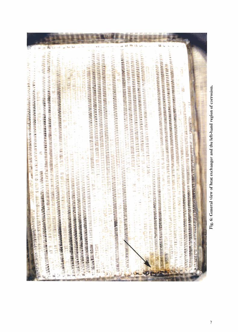
The only identified corrosion occurred on the flight-spare condensate heat exchanger. No problemreport was available but photographs were provided (see Figures 6 and 7) and indicated that thecorrosion was initiated by residual salt flux from the dip brazing fabrication process. These fluxes arecomposed of mixed salts (e.g. sodium chloride 23.0%, potassium chloride 47.5%, lithium chloride24.7% and remainder sodium fluoride). The brazing operation is performed at GOODCwhen the salt ismolten. On cooling to room temperature, all residual flux must be removed. The cleaning operationcan be monitored by a silver nitrate test to ensure contamination-free flight equipment [2].
4.2. Water Condensation
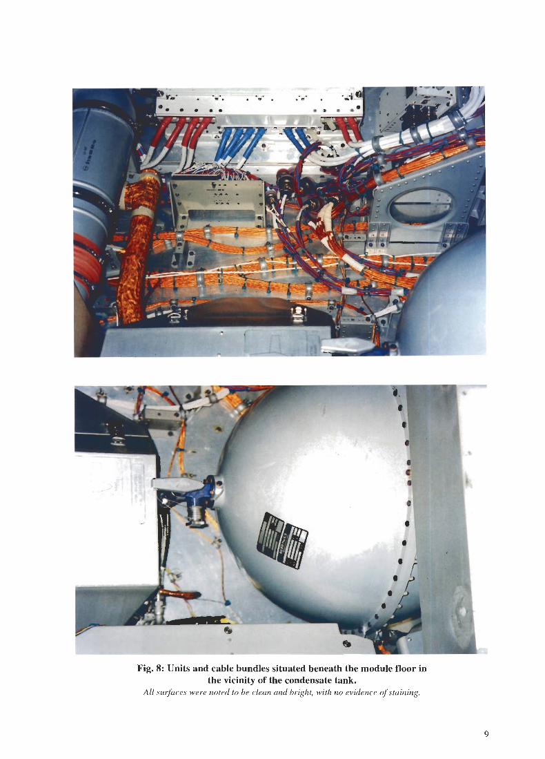
Concern had been raised that the condensation of water vapour on to cold surfaces during flightoperation might have introduced corrosion. Extensive inspections were made of racks, the modulewalls and beneath the module floor (e.g. Figure 8). No evidence of corrosion or staining wasobserved.
3

a.q
..
/~
.:'\
"V
/\r. .,
/-..
~
Fig. 2: Aft end cone, showing the fire extinguisher, hand rails and foot support.
All panels are chromic acid anodised.
All welds are ground, polished and brush alodined, as indicated by the arrows.
(1979 photograph)
4

-,.~;.~
~- I---
.-!";.'.'--=-,
i I#U .:::".. I.. .
---- -
I .I I
/ L""- .;..,---
"
-I
...
-..,I
~000\....OJ)c::"i:='"0UrfJ~
... ~olJ~
5

(; 0
Q.l
C
U--G:l
() tJ ~
"'~(;
\;; \or
(
,()J\
~
~
0_,,-.A,A
..-
(1
('(}
~,
() 0...... «'lIt ..
,:~~
Fig. 4: Brush alodined weldment (arrowed) in 1997, showing no evidence of corrosion.
\
.t'
,,-
Fig. 5: Macro-photograph of 20 mm wide "weld zone" between anodised panels.After extensive inspection of many metres of weld length,
only this small region was found to suffer from lines of tarnish (arrowed).
They were not associated with any corrosion products and appear to have no depth.
6
..
--.---- _.
:~~- -- ---- ,=- -- -
""--. -.. ~ -: - -- - - -.::::~- --- -- -
"'- ,,::.'
~ ~.- -- -=.-:- -~:: =-- -- -- =- - - -:==.: =
==..=-=:==;::::::
~ r~ ~- -- -='=
it:: ~ :::-~-===
- -
- ::~ ;=: ~..::: --=":: ;:;= :=- -- -= ~- =:- -- -- -.= -~~- -- - .....
- -;:J.-::'
~~-",:-- -":.!:::~-- ~ ~
";,1
~ - ;: " "'. :--". ::: -- .,..."..,..---.'- - -- ... :::"'-'"~ -- - --: --~};~-
~'-~E _ ::e:: .~~ ~ .::; "-: .-
r - -~
~: ~::;:
~
... ,... :::',,; rt .= _:
"#~ ,'::-.
"'"'~ . ::::,. ~
".::::
J.,,,,~ ~ '
-..==
~ 'r .::::.:- .:=4""'T::::; :::::-~'
,~ ..:; -~,,, ~~-:.:;:: "-::~~ 1; ~ - ...--.,,,' ..,;~ ...ti. t;.. '"::;: ~;;-.~:. :.:!,: ~ f'1'<'::::; :~ :...
.~~-
=-'t ~--
.;:.;: -" <'"~ ~~ ~~-- ~
::::
~.. ..~.. .. ..
---------_.~==;:::.
-= :-: ~ ::=;:=7:.:=;::::7-''''-- -~ ~ :::: ..,-~.. :-;::r::--:::.:::
::;:--"" G
-
~ ~ S~ """... '=-'''-. ;::- =
£::... '-~ ..~-'- .- -:;:.; " ::-o.t.-- ~ ~ --
. .
...;.":- ----.:;.-= ~
-'" .~ := :::_._-
-;;::-::::;,':::;-=:"':..":::::~~--::----
~:::~=----===:==----=-=::===:::.~~-- ---- - --:===-::::.=:--
-.~<r..
:tc=.
I;:
- -
---=::--,....
...:;:;
-::""'-- -" ---. :::: --=: -:::=- -- ---;?~:--" --== :: =--'
:.-_-..~ .:::::::-~:s:::=: .=:.--- - -.:::-:.:.:::: :-::::::;:::=.:-:-=:::..:::=:-:-~---==:::':---= =: ==;; --::::::::::--==~;;~J-:::==:::---"'-"-------- - """"""-~'-"---::; ::: '::= == -~~:::~-'-:; ~ ::: =
:......'-:. -:: ;:!!.;;: ~.~~~~=~~:;;:;a-::::~'-'--,~ ~ "': = ,::: ..''::; ~:.: ~ -:::.:-==.~ ~ :;: ~
~.::'"':::..'~,;:::.~~~;;:::;!:if~~OO::::;=.....::~~=~? ~ -~ :::: ,:.,.J.--
"-'" --""'........'" -:; "'.. --., ~
> . .ot;- .".'~i "
1f'.I
~~ ~l",*''''1'- '11-
- - "'.:>--".-. .....
~-. -.....---';:::;-~-
., ~-~ .. t ;::::t:E
==.--~;;::.:a--.....---.--.-.....--.-......-~~-'.---0;;::~
.oatit- ... t1.'
-.;;~' -- ::-- -.-::~=-:.:.-§.. -= -:. :;.S-::=--?
~~~!~:;~=:§:==-::=~=:::::===-- ------~-~~~-----=::-==='::: ':= ::: == ==::==-- =;-:====::-==:::==--=-=:::=:=--=:.:.=====:::=:-;:;:
-- ::::: --- ~:--:::::- -
---.-=..,...--
-=,
--- =-- :::: :-..::.----.---:'"':':-::::::-::::::-*' :;- ---~=
, ........
:- ~ ~--:!:::: - ----- --
- -
-'----------. ----::::::::.;-~-:::;::::::::::::~
'==
-:; ';.~g=:~-::::: ~~ ':;t.;;';;""3.-- ;"". -,.,= ::: ""-' '=:-~~"""!#=:-- ~.-- - --==-;.~~§~~
-= ':.~~--- --=.:",:::':;:;
---===.==:=====~::.=:-=::::=:::-- - ----- -:::::=::::::- -- -- - --- -==:;;§=-~- --:=:--- - -- 'f"-~§~~:: ~ ~ ~ '-=1
;~~~~i~_.- - ~ ;; -- ~ ~~=~: =:!- - -::... ~?I
~ ~ -.:S;::::1:-~r'" -~~'- -=:~~ ==;;~
- =- ;:;.-...:;., ;::; ;;.
~=~- § ~ ~::~E1::: :;; ~:;'"-:::~::-~~:=~~-----~.:: 5. ==~\'= ==~r:.:~'=='
::: -;:j', !:;. :: ~.l~
~~m~
.
'
~E-~~§~tj;i, :::;,:..::" ~.. ~..~~t;- - ~I~ ~.~~- :- S :;'??~_.~~? ::$
,
~; ~a ~.::-:: ~~:-'"
--~... ..
'-_.-
~
.~- ~ ....
- -.- --=:wE
..
-:;
tI
..I~
\~
t
~.
..
....
,", .
=,~
'"0I-<I-<0U
....0
=0'6iJQ,j
I-<
"0
=~-=I<:::
~Q,j
-=....
"0=~I-<Q,jOJ)
=~-=u~Q,j
....~Q,j
-=....0
~Q,j
'S:-;I-<Q,j
=Q,j
~
\C
~~
7

....
.....
~
------ .,...~~-
.." .--~
..,.,.'"lIIIIIIiIiIIiIr-'-~
....
.. -,...--.. r
"" W" -.ye"'-~
,~~.-,~
~',.;:;,1.'" \
\cic
11lio*'ii-- """"..
-"'"- -.-""""'"\
-- -,- ............. ~.. .....
,"' .IIf/I" ,..,'
.), -~t
..,.. 's."
8
- -.' -~;Ir ... --'....-
--.... ------................. - --------
--<if".,.....-..... --""'"r -
- .-A... ",',"'\.
~}!., «""'c.}t~:,-{~','~...
tift ...,'.'~.. ,-~""~')'
~~G'"
-'~
- --- ~- """-
- ~""" -"'"
~ .. .A..JI
...~ .........----
~~--...
\ ~ --~/~
",..'.
-'~~~~. ..~tt~j'-tC
.".'; ~
~....-....-
~':f"~. ~
...
-L --""'"
~
~.<If
....-
.....
~$Ii;~rg;;~:.;r~SI
Jft\
--., -y,,~- - ,.,.. -",Pn.
- .,...- ...........
,..A
~~-
~
...r--=~ -aL
..... ...... ..-.......
---....-..III"""""
...,...i
-'.....
-- - -. ~ ,
' .~- ~d.,.,r- - it"'--
~
- riJ~
--- .g
4 '~...".-
J,.;
1 --- ~
,- ~ e§..r- JJI<
, ,... e",... 0~ .t:
.J ....:;
~~.. J,.;
~o~ -;:
~~'" c..
. ,.: '" c..--."""" ~
~
,. ~..." .,.'....L ~ ~; ~ 14..f '. -, ~
~~ ','.8
~;a-i. '~J
~=:~
e=
'2's=c;
~~
~0J,.;J,.;0u~
-=E-<
r=-:
oiJ~
.-~
~..-, - ...
-- , -), "\
~~.,':. .~~
\1
110..-
...,......
~
-
If"'""L
~
~ ~
..-/
~.., ...:",,,,,1
,;!!
. . ., . "
..---,.
.
{ "....fill
.,'I
<01
:\
l I
\\,
~ ~
- - ..- - - ------ - -Fig. 8: Units and cable bundles situated beneath the module floor in
the vicinity of the condensate tank.All surfaces were noted to be clean and bright, with no evidence of staining.
9

- ---~
~. .~O.0::::::\~
_II
/
tf
Fig. 9: Detail, showing some small areas of paint that were removed from rounded cornersduring ground handling operations
~80
-.- ~
01 .
'" .--
.
-..... ..
~.;;..... .
>.
~..
... o(0.
~' ~
Fig. 10: Solar blankets appear undamaged.There is only a slight darkening of the cloth surrounding the ESA emblem.
None of the colours has degraded (cf new cloth during flight -page 8).
10

4.3. Painted Surfaces and Optical Properties
Paint peeling, flaking or degradation of optical properties had not been experienced on flight standardhardware (although some rework painting of the EM OFT Pallets was necessary prior to flight). TheChemglaze paint adhesion was generally excellent and only one region of paint detachment was seenduring the inspection (see Figure 9). This occurred at the corner of a pallet part and was attributed tohandling activities. However it was mentioned that when an element returned from orbit there was abarely discernible bluish hue on the thermal blankets, but after a few days the blankets returned totheir normal appearance.
Measurements of the optical properties of the blankets (Figure 10) always gave values within theacceptable range. Chemglaze paint on the pallets was reported to show a similar phenomenon. Someinvestigators consider that these visual effects are related to very minute amounts of siliconecontamination which became modified by exposure to ultra violet radiation and atomic oxygen inorbit [3].
4.4. Mechanical Damage to Thermal Protection Systems
4.4.1. Thermal Blankets
Thermal blanket degradation, caused by wear and handling problems had occurred. It was concludedthat handling damage was much more significant than degradation caused by exposure of theseblankets to the orbit environment. The inner layer of all thermal blankets had been replaced by Nomexbecause of splitting and tearing of the original material (see Figures II and 12). Blankets with smallbend radii were most susceptible to damage.
NASA logos are now painted directly on to Nomex cloth because less colour degradation isexperienced.
Recent NASA servicing of the Hubble Space Telescope found increased thermal blanket degradationthat is considered to be caused by long exposure to radiation.
4.4.2. Handling Problems
The blanket attachment devices caused problems that were relatively easy to resolve on ground butmuch more difficult to correct in orbit during the crew's extra vehicular activity (EVA). The blanketsare held in place by plastic spigots with ball ends (poppets) which pass through eyelets in theblankets. The poppets snap into split stainless steel tubular retainers which are bonded to the exteriorsurface of the structure (see Figure 13). On mounting the blankets, difficulties may be experiencedinserting the poppets into the retainers, resulting in a sector of the retainer bending over, therebypreventing proper insertion before a repair is performed. On occasions the friction in the retainer hascaused the spigot to break, leaving the poppet lodged in the retainer. Once again, a repair in orbit mayprove very difficult (see Figure 14).
4.5. Interface Problems
4.5.1. Wear and Friction on Trunnions and Mounting Points
There has been no identified degradation of the bearing surfaces of the ESA-supplied trunnions. Arecent investigation of a surface defect on the Main Module Trunnion, Serial No. 001, found that thesuspected damage was a deposit of aluminium alloy with trace amounts of hydrocarbon [4]. Thesource of the deposit was deemed to be the aluminium-rich coating used in the 'J' hooks in the VerticalProcessing Facility. Sustained loads on the coating can cause pick-up on the other side of thatinterface (see Figure 15). Cold-welding and the transfer of aluminium can occur on to the hardchromium-plated trunnion and this metallic contact combination is not desirable (see also [2]). It is
II

JI
~I
Fig. 11: De-lamination of goldised-Kapton thermal blanket, caused by repeated handling.
Fig. 12: Although it is hardly noticeable on this photograph, dark "staining" of this area of thegoldised film has occurred during operational life.
12

.,
~~..t.o:r rJ ~''<'''''00"'O,,!< "'+;°-1
'1...1-'Y",
~..:i~.
.
.'~
.
~>0 vo"
.'"'"
~~.' '".,"-~:.,'w ~~ 0'.
;'."~."".\;,.y2,,':
.'u'W ""'.(-,"'~-<P'
"""9-,&~'."'", "-,20'
~ '<-,> J,'%! .".
,j:~ 6'",-«. ~.l.,O#Jci~
Y)
."""",,;'-0'0 "'.>.'»-t.~,;,y:,;:::~f./~& J'"/u-U'.t;,~"P.y..('A ~>...\,/,~~?p~
'0(>.~t.b..."'~~'7;- . c~ ~v~°0.
~oo c.t?QQ
v~ #~/
"'qv~-~~
,.~b;'u>
;:J
.<a ~'b
ov"&,"3-19Q
'<;'>
<::~. ..t{b.5'4-'?,,,,,'~
'Y,I'Ioc;.A',,,.,,.'- .,;
~gI ~\/ "
>" ~/'
,a
""\.
\
JFig. 13: Plastic attachment devices for holding blankets.
These are easily de-assembled and the plastic ring shown here can uncontrollably spring away from theretaining groove of the tubular post during flight.
f,'!!
Fig. 14: Stainless steel retainers for thermal blanket attachment.
These parts are seen here adhesively bonded to an Igloo side wall. The spring-like spigots can
bend, or break leaving the blanket poppets in the retainer. The arrow indicates the locationof an electron beam weld run-out. The entire aluminium alloy .I'll/face has been anodised.
13
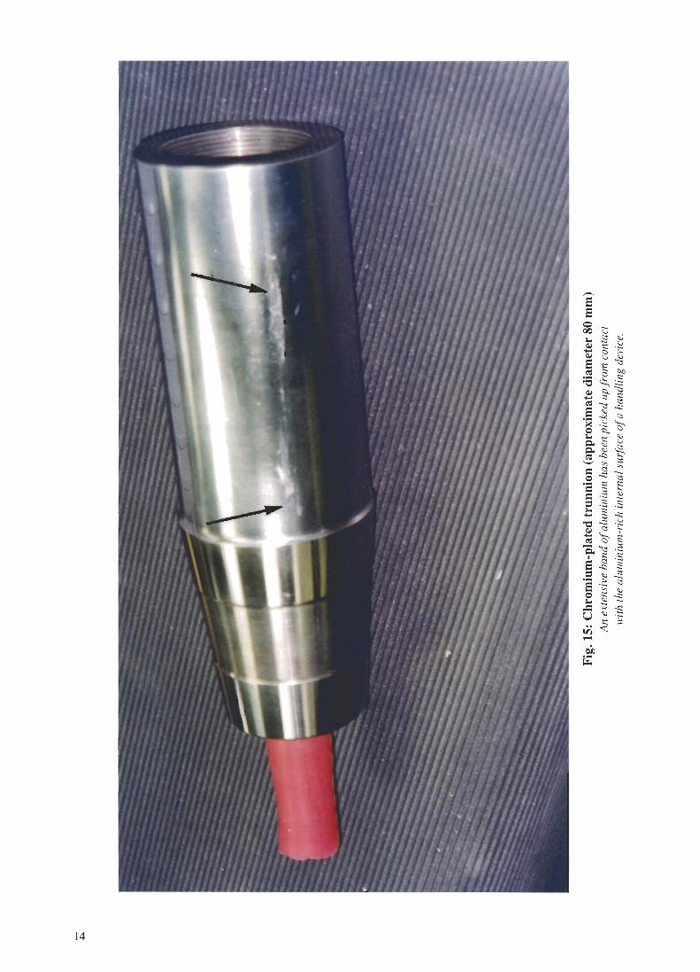
14
'58
0 ...00 \..)
1-0(:j <>.i
~ '=:: .::
~ 8 ~~ - "1:::1
~:: C()C) :::
~ <1::.,:..:::
~ §- ~~ "1:::1
(:j
8 '"~
.- :::c:i:j~ .:: ~e ~ ~~ <;;
\..)
~~'@,'-' '"
::::
=:(:j '"
o~~-= E:
::::... ::::
....
=: .;:: ~
8 .~ .S::: ...s::
"0 ~ .~Q,I (:j ....
~~~Q."1:::I .;::
I ::: :::8 .2
.~
=s
.- ~ ...:::8 .~
(:j
0 ::: '"1-0 '"
~-=~:;;u "'.';::.r; ~
;:
.-;ojJ
~

probable that the transferred aluminium could be removed by swabbing the affected surface with aweak solution of sodium hydroxide.
4.5.2. Rack Cooling Air Ducts
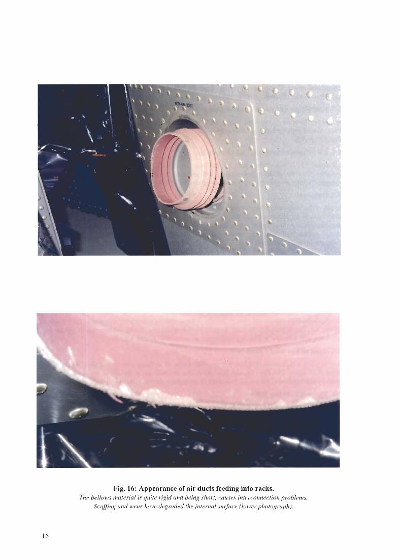
The ducting/bellows interface at the base of the racks created problems because the bellows materialis very rigid. A more flexible material would make the connection and clamp securing operations lessdifficult and reduce the amount of damage to and splitting of the bellows (see Figure 16). Such aninterface would be extremely difficult to make in orbit.
4.5.3. Keel Fitting - Spacelab Transfer Tunnel
The passive location of the Keel Fitting made the mating of the Spacelab Transfer Tunnel to theOrbiter a more difficult task than it would be with an active device as used on the Spacelab Module toOrbiter Keel Fitting.
4.5.4. Line Replacement Unit (LRU) Interfaces
Exchanging LRUs was complicated by the large number of fasteners and washers required formounting, plus the difficulty of making and securing the wide range of electrical connectorsemployed. A less complicated solution is recommended for COF in-orbit activities.
4.5.5. Fasteners
The use of the ultrasonic extensiometer for the setting of bolt pre-loads was a very complex task andreplacement of the transducers was frequently required. It is appreciated that their use was driven by adesign modification introduced late in the programme. This difficult method of checking the actualstresses within bolt materials would establish that no fasteners were loaded beyond theirrecommended maximum stress level.
Aluminium-rich coating on the Pallet Keel and Hard Point attachments bolts had a tendency to adhereto the nuts after long periods (approximately 1 year) of sustained loads. After de-mating the coatinghad to be removed before re-mating was possible.
NASA does not use aluminium-rich coating for this application.
4.5.6. Captive Nuts
The rounding-off of captive-nut corners, mainly in Racks and the subsequent spinning of the nut whenapplying torque was probably the most frequent problem experienced. One solution was to replace thecaptive nut with a loose nut. This is probably not an acceptable in-orbit solution.
4.5.7. Wear of Electrical Connectors
Wear was not a significant problem but the wide range of securing screws and their accessibilitycreated difficulties. The Pyro Control Box suffered a short-circuit at the connector feed when theprotective cap touched a live pin, an indication of inadequate clearance and a live male pin interface.
4.5.8 Thermal Interface Filler
The thermal interface filler, Chotherm Sheet, proved to be suitable for single use only, due to itsfragility. If it were to be used in the COF, it might present difficulties in replacement in-orbit. It wasrecommended that standard thermal interfaces be designed, e.g. an adapter plate for the MMU.
4.5.9. Fluid Disconnect Problems
The only problem experienced was during Spacelab 2 processing in 1985 when the Freon 21 QuickDisconnect coupling failed due to over-travel. The failure mode was that the split ring retainer wasforced out of its location groove by holding down the position locator button and rotating theactuating sleeve beyond the fully closed position. This allowed the support to separate from the body.
]5
'C. \...
.......
~ -..
I.
.,
...
...
\.~J
'0..~,
ci'.'-t1
Fig. 16: Appearance of air ducts feeding into racks.The bellows material is quite rigid and being short, causes interconnection problems.
Scuffing and wear have degraded the internal surface (lower photograph).
16

The recommended preventative action was to increase operator training and certification [5] and therewere no subsequent failures. If the same design is still to be employed on the COF hardware it will beessential to perform similar training for all operators. These fluid disconnect procedures must be wellunderstood during both ground and flight operations.
4.5.10. Threaded Connections
Captive systems were sometimes difficult to locate and operate.
4.5.11. Accidental Damage
Damage occurred to the Module Floor during Rack handling operations (see Figure 17). Improvedfloor protection covers were manufactured and were used as required in Modules, Pallets etc.
4.6 Limited Life Items and Physical Degradation
4.6.1 Seals and Associated LeakRates
No seal failures were experienced during processing at KSC, thus verifying the corrective measurestaken following the leak in the Water Separator in Europe in 1980 and the Igloo "Gask-O-Seal"problem that occurred during the Spacelab 2 acceptance-level tests performed during 1982.
4.6.2 Relief Valves, Positive and Negative Pressure
The relief valves were cycled prior to each mission and the only anomaly noted was when the ModulePressure Relief Valve (MPRV) (Negative) Popper was not rotated to the neutral position. This wasnot considered to be a problem. When cycled, all valves operated within their specified tolerances.
4.6.3 Brush Motors, Start-up After Long Periods of Non-Activation
The single occurrence of this type of problem was the failure of the oxygen latching valve in the02N2 Control Panel [6]. The cause of the non-operation of the valve was determined to beoff-gassing products from the silicone compound in the brush motor assembly, contaminating thebrushes and commutator. Corrective action was limited to annual measurements of the resistancevalues and the operation of the valves. Design or Material changes were apparently left as a customeroption while no firm recommendation was made concerning the implementation of a post-curing heat-treatment to reduce or eliminate off-gassing of this silicone material.
If the same design is still valid for the COF, it is recommended that the crew be required to activatethese valves and to measure resistance values at more frequent intervals in orbit.
4.6.4 Harness Attachment Points and Insulation Damage
The harness wire and cables suffered damage which was determined have been introduced by bothoperator handling and the natural ageing of the wires' insulation jacket. Kapton outer insulation wasthe most susceptible to handling damage, which resulted in splits and tears of the Kapton wrap andexposure of the shielding braid (see Figures 18 and 19). MDAC submitted samples of damaged wiresto the NASA KSC Materials Laboratory for failure analysis in January 1991. The findings of theanalysis resulted in the issue of a standard repair procedure for Spacelab wire aJid harness insulationdamage. Kapton and PTFE insulation are addressed, as may be seen in the Failure Analysis andrecommended repair procedure [7].
It is of interest to note that the International Space Station baseline is to use Teflon-coated Kaptoninsulation, which will be less susceptible to handling damage than unprotected Kapton. However theflaking of the colour code PTFE (Kapton) layer on the ESA-supplied wire may still present acontamination source due to ageing and handling degradation over the 15-year life of the COP. Itshould also be considered that, based on Spacelab experience, damage may also occur to the Tefloncoated Kapton wire if in-orbit maintenance is performed. Except for the incident shown in Figure 18,the harness attachment points did not present problems.
17

'C"""""""
. ~ ~'.
j.,
y.
Fig. 17: General view of the Module Floor, as removed from the spacecraft.
Damage and staining are visible in the lower photograph.
The floor finish is anodised aluminium, which should perhaps be better sealed,
to reduce absorption of liquids and to improve cleanability.
]8

~
Fig. 18: Photograph taken by NASA in 1995 to illustratedamaged Kapton insulation around a cable attachment point.
The bend radius of the braided cable appears to be too small.
I
<Iii
19

Fig. 19: Detailed view of aged Spacelab wire bundle.
It is probably J8 years sillce this was mallufaclllred by Rheillshagell.
The outer layer of the wrapped Kapton has crazed alld embrittled,
with some very small flakes being shed. (Wires, held ill storage by
Estec QMM and made by the same manufacturer at about the same
time and to the same specificatioll, show 110visible degradatioll).
20

4.6.5 Spliced Joints in Harnesses
The ESA method of splicing wires as a Jommg process was questioned by NASA during theintegration process of Spacelab 2. The evaluation of the process included discussions at ESTEC withNASA and a presentation of ESA's rationale for accepting splicing as a qualified process. The finaldisposition by NASA was to rework the IPS harness and eliminate all spliced joints. The Follow onProduction (FOP) IPS harness was not reworked but has not been flown on a mission. Splicing is stillan ESA-approved wire joining process.
4.6.6 Red-Plague
The existence of red-plague in wire harnesses used in Space Station hardware has recently beenreported by MDAC and confirmed by MSFC metallurgical analysis [8]. This wire was not ESA-procured and was purchased in the US to a Mil. Spec. Micro-section analysis showed it to support avery thin, porous layer of silver plating. The ESA requirement for all wire strands is for a minimum of2.0 microns of silver-plate in anyone location around each copper strand. Additionally, red-plaguescreening tests are required [9 - II] for all wires utilised on ESA space projects. This serves to remindusers to maintain their vigilance in process control, screening and quality tasks, to eliminate theoccurrence of red-plague from their hardware.
4.6.7 Condensate Heat Exchanger (CHX)
The hydrophilic coating of the CHX is common to Spacelab and the COF. Because the COF coatingwill be European sourced, the performance of the Spacelab hardware is therefore pertinent. Therewere no problems on Spacelab although there was an observable difference in the behaviour of thecoatings on the Spacelab I and FOP items, i.e. the liquid on the surface of the Spacelab I coatingdispersed readily to produce an overall wetting while liquid on the FOP surface formed into isolatedglobules. This phenomenon did not result in any water flow problems.
4.6.8 Tin Whiskers
Long filaments of tin, known as tin whiskers, can grow on tin-plated items. These whiskers have adiameter of between 0.1 and 0.5 microns, and can grow to a length exceeding 2 mm. As they areelectrically conductive (32 mA can be carried by an average sized whisker), it is common to forbid theuse of tin-plating on spacecraft hardware [2]. Tin whisker growths were reported, during the forum, tohave caused the failure of a relay in the System Power Distribution Box (SPDB) - they had createdelectrical short-circuits.
4.6.9 Fuse Holder Failures
The failure investigation of a blown fuse from the Igloo SPDB, during processing of the Astro 1mission in 1985, concluded that the probable cause of the failure was over-stressing due tomishandling. Further fuse failures, at currents lower than their rated values, led to more investigationin 1990, which identified a design problem in the fuse holders. A swaged joint, at the wire terminationto the spring loaded contact to the fuse, created a hot spot during current flow, thereby causing localthermal over-stress. The selection of COF fuse holder design should avoid the use of swagedterminations, to prevent similar failures [12].
Spacelab fuse holders with crimped terminations did not suffer failures and crimped joints became thebaseline.
4.6.10 Degradation of Foam
The most obvious form of degradation observed was that of Pyrel foam which was utilised for soundinsulation and packaging in toolboxes, work boxes and drawers. The foam began to decompose andbreak up into pieces ranging from particles to clumps with a soft sticky consistency (see Figures 20and 2]). Replacement became necessary after approximately 6 years and the substitute selected wasSolamide 30] coated with RTV 142 or Kapton tape. The Solamide was also found to shed particlesand needs to be suitably covered in order to contain these small-sized particulate contaminants.Foamed aluminium with a density of 0.48 g/cm3 has excellent sound absorption properties and isavailable in Europe under the trade name of Alulight [2].
21

~
~w P'V
-~..
r .- .-.\--I
-I --~I,. ~
I~
'.J
I
~*II
,.
...,.II
.-- ~/ !
/ '~-p;r,{ /
, ,
"...~.'-
.;"".
., ,- ~~~'.~~. ~'
4.'( ,~~'.;L' , ' ,
'~~i'f.'p' . --~. .~;v
./ .(,'-- .~~' I 0
Fig. 20: New on-board tool holder made from Solamide 301 foam.(Compare with Fig. 21)
22

I
It-
...,'*
,~.~
*1Fig. 21' P
WhenTh, tool hold.
yrel roam after 6
compressed by slight h
er
d
(upper photogra ph) Iyears of use.
an /in.
ws co Ig, It pulverises to th
mp etely degraded
e powder seen in the I~wer p hot ograph.
23

.. W e
;.d; e
. " "5 .. ..::i g-- ,
8'-!:;;~ II lib ,
~ i"..! \ i- ':;:"~ i
~ ~:g1- '"~
; Z."r i
><l '-::--0:::
' "-.......
v jo(-*~ ~. ..~ ~~& ~ 3
~ I''''''''''.~I
5 ~ .. ::i g._l 8 -!:;;
~--- II ~ ~~ :r - ! ~ ~ :! ~
.-.,.,?~ iO! ...,:: ..!:?.3.--.~ t.-;.} -:..v >(..~
-*~ ~.." I I ~ig ~ &
~..
- i ~ <.
.~~~ ~O;;)
r~
}it
.~
..~ ~,
'i' --...I
~//1
'(~
r~. CJ ...iiL- .-:...~..
/1;t
- - ~
_!-
~ . rr;:::_.~t -
7_'; .i- :.1'"
-,"
S_- ~~ ~ .~.GJO .. ~
it
f -1111'1 :.~!~..~.i !J-I . \ .. . -iO'
.~.'~UD t: .: . -, . ..~!~ - t~ I. ~~".io- . -..
...~
24
"1.....
I00" !.~!"...' '.
= .. ..: ,
~ f A~ t "~" r".:.II,.'--
I ' ....
~ i "eo ;'&1.~ '- -...
- -!'Qi.e~. .
..,..,
":"'"'---
\,
~
.tt). 411...r--
~...,. ;,
"'.(:.,.
~'1:I
-::---f:,
"
.1 _I( ~
f, ~
't:i ,;,Q) Q);... ".3 ~0"'"Q) S;... Q)Q).c::;... ....~
'"'"
Q); c::Q) (,J
".'.::0 ~u'". Q)
t:-s~ Q)
= "0 0(,J.c- ~~ Q)
="0Q)="0 ;...
.- ....(,J 0(,J ;...~ Q.,""....~ ~.- -=~ ....01)",~ ;...
"0~
Q).c;;.-.
~.c"""00 Q)
;"'''0Q., .-;;'-'''- 0.. o1j Q);'". ~ Q.,
= .~0"=Q)
0"0 .-~ ....
=(,J
.- Q)Q) ....;... 0
~;...Q.,
.c:: ~Q.,~~.c::;... Q.,OI)~0 ;...
01)0 0
.c::""Q.,~0::: Q.,
Q) ....-.c::
. ].~;...=';;;'.-
='" 0Q) .-
.c::""(,J ~(,J
.- 0~-"'~Q) (,J
.c:: ~~ ;...
;..... Q)
('1.c::('1....~o.- =~-

This could be considered, subject to satisfactory qualification, as an alternative to the organic foammaterials.
4.6.11 Microbial Contamination
No evidence of microbial contamination or dust accumulation was observed during pre- or post-flightprocessing, although microbial contamination checks were performed periodically by NASA. Afterthe IML mission the Cabin and Avionics loop air filters were investigated and of the 40 samples taken29 "responses" were recorded. Approximately 17 bacterial species were identified, together with onevariety of fungus. Detailed results were compared with the findings of the (STS 40) microbialinvestigation and are presented in [13].
4.6.12 High Data Rate Recorder (HDRR)
As known, corrective maintenance was performed on the HDRR by the crew during the Spacelab Imission. The HDRR was replaced several times throughout the Spacelab history.
4.6.13 Crew Interface Aspects
Switch guards have been supplemented with plastic covers which clip over the original guards. Thiswas necessary because accidental switching was possible by the astronauts' toes during zero-gravityactivities (see Figure 22).
The cover plates/lids of some equipment, e.g. the power control box (PCB) and electrical powerdistribution box (EPDB), are considered too flexible, because under crew-induced loads they deformsufficiently to create potential hazards.
4.6.14 Equipment Obsolescence and Spares
In the early years of Spacelab, delays were experienced in processing tasks because of thenon-availability of spare parts. This was later improved by better identification of so-called "longlead-time items" and early procurement of spares for these. MGSE spares for slings and hoistingequipment were a particular problem because some German DIN specifications used were obsolete atthe time of delivery of the equipment to KSC.
4.6.15 Detachment of Tape
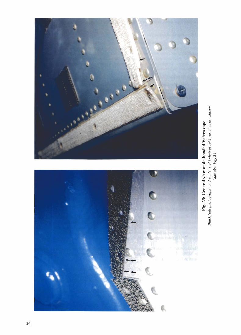
Instances of slight Velcro tape lifting were noted on a few of the Spacelab racks. This had occurredmainly at rack corners and in places where the tape was positioned over raised rivet-heads. Figures 23and 24 show the adhesive beneath the tape to be patchy and a continuous film might be preferable.
4.7. Examination of MLI Hold-down Button
A particularly interesting aspect of the visit was the inspection of post-flight multi-layer insulation(MU) blankets and goldized Kapton blankets in the KSC Sewing Room (see also Figures 11-13). Therecent change to Nomex cloth blankets also incorporates the use of very fine stranded stainless steelwire. This wire is sown to join the Nomex cloths and enables the blankets to be electrically grounded.The various MU blanket assembly methods were demonstrated during this sewing-room visit.
A MU hold-down button that had been used on a previous flight (duration and details not known) wasgiven to ESTEC. This has been examined in the ESTEC metallurgical laboratory [14] and the resultscan be seen in Figures 25 to 29.
The button surface has become visually dull following its exposure to the LEO environment. Thesurface immediately beneath the lacing tape remained bright and shiny (green-brown colour) however.The figures show that lacing tape had protected the button's surface from attack by atomic oxygen.
A further remarkable observation, is the presence of an impact point (only about 120 microns indiameter) on the button surface. This is shown in Figures 30 and 31.
25
~-, ,- r'
1 \ ))
~J
I
(
(
(
(
t"
\
26
~c-..:::..,
'".
"-Q) ~Q.. ..,
~'""-
0 .~r..
"-~ ~Q)--..
>-..:::~ ~Q)
CQ]2~0 c '<I-.Q-":::~~ ~"::O~ ~Lt.,
'0 E- .g
~ ~ ~.S:!~ ~;.. ;: ~-;~~ ~=--..
r~~"-' ~.. CQr<') 2N C
.-..:::
.!:!' ~~q::,
~.......~
"~~

'" I
/'
~..'r;;Q)..c:"0~.....0....=='08~Q)....~='0-Q)
"0~,5"0=~Q)(,J
..:s'"'='<I)
~(,J~'"'8=''is
's='';
'"'~=~
Q..I=0=Oil=.~0
..c:<I)Q)~Q..~~0'"'(,J
Q);,
"0Q)
~.....0
-';....Q)~-.:rNoiJ
~
27

.~ . \
';; !
rJ. \
*t
.,.,,
I
"}'$,, .\ \ .
\, \.
t: ~'I
i~.) , ..'i
f
I.'~
J.\ .~
,II
.. ~4m~. ~',L;.ri)~ J
Fig. 25: Post-flight MLI hold-down button, as seen by optical microscopy.Note the protective shadow (light band) produced by lacing tape.
28

Fig. 26: SEM photograph of the non-attacked centre area of the button,showing a typical polymer surface (Magnification x7500).
Fig. 27: SEM photograph of the border between the atox-attacked and the non-attacked area.
This border is quite sharp (10011111)(Magnification x500).
29

Fig. 28: SEM photograph of the atox-attacked area.This shows the typical cone-shaped features of an attacked polymer (MaRn~fication x 1000).
Fig. 29: Same as Fig. 28, but higher magnification (x7500).This clearly shows the cone type structures from the atomic oxygen attack (cf. Fig. 26).
30

Fig. 30: A molten circle in the atox-attacked area.
This feature is probably due to micrometeoroidldebris impact during the life of the button on Spacelab.
Note the irregular shaped halo around the impact. This consists of atox-attacked polymer,
but with a much finer structure than the surrounding surface. (Magnification x250).
Fig. 31: Same as Fig. 30, but showing the centre area of the impact.(Magnification x2500).
31

This page deliberately left blank
32

4.8. Space Station International Standard Payload Racks (ISPR)
The MSL payload recently integrated at KSC included an ISPR which necessitated modification ofthe Spacelab Rack Support Structure to simulate the Space Station-to-ISPR interface. Considerabledifficulties were experienced inserting the rear retaining pins at the base of the ISPR, even with therelatively good access and the use of fibre optics viewing equipment. In the opinion of the technicianswho performed the integration there will be serious problems inserting the rear retaining pins in orbit.The experience of the MSL ISPR integration should be evaluated by the responsible ISPR designauthorities and improvements made if necessary.
5. Acknowledgements
The cooperation and kindness of the NASA and MDAC personnel in providing access to the Spacelabhardware and supplying the records requested is greatly appreciated. Particularly thanks are expressedto Joe Lacovitch, John Link and Melodie Porta (NASA) and to Keith Manning (MDAC).
33

This page deliberately left blank
34

References
[I] Dunn, B.D., "The corrosion of Spacelab structural alloy aluminium 2219-T851 ",ESA STR-212, 1984.
[2] Dunn, B.D, "Metallurgical Assessment of Spacecraft Parts, Materials and Processes",John Wiley and Sons, Chichester and New York, 1997.
[3] Leger, LJ., M. McCargo. et aI., "Third European Symposium on Spacecraft Materialsin a Space Environment", ESA SP-232, pp 78-98, 1985.
[4] "Area of Scratches on Trunnion Mating Surface", Report 96-IC0599, NASA KSC Materialsand Chemical Analysis Branch, 14thNov. 1996.
[5] "Trip Report - Symetrics, Inc (Quick Disconnects)", SM85-396, MDAC/KSC,13thNov.1985.
[6] "Failure Analysis Report - 02N2 Control Panel", FAR90-27, Carleton Inc, loth July 1990.
[7] "Repair of Electrical Wire and Cable Insulation", A90-901-RKB-93035, MDAC/HSY,2ndAug. 1993.
[8] "Examination of McDonnell Douglas Aerospace Wire Harness", Metallurgical EngineeringWork Order Number 96-203, NASA/MSFC.
[9] "Determination of the susceptibility of silver-plated copper wire/cable to 'Red Plague'corrosion", ESA PSS 01-720,1985.
[10] Anthony, P.L. and a.M. Brown, "Red Plague Corrosion", Materials Protection, vol. 4, no.3,1965, pp 8-18.
[11] Dunn, B.D. et aI, "Corrosion of Silver-plated Copper Conductors", ESA Journal, Y 01. 8,pp307-335,1984.
[12] "Failure Analysis", Spacelab Anomaly Notice, SAN-FLT-H W - 069,MDAC/KSC, ih Feb. 1990.
[13] "IML-I Filter Debris Characterization and Weights", MSFC-IML,. NASA/MSFC,I st Aug. 1992.
[14] Rooij, A. de, "Examination of MLI Hold-down Button", ESTEC Metallurgy ReportNo. 2351,1997.
35

This page deliberately left blank
36

Annex 1 Discussion Topics
Agenda
Problem Areas for Possible Inspection and/or Discussion.
CorrosionAlodined weld and heat affected zones.Anodised surface degradation.Condensation and cold areas.
Painted SurfacesPeeling, flaking.Degradation of optical properties.Atomic oxygen effects.
Thermal ProtectionThermal blanket degradation.Wear, tarnishing etc.Handling problems.
Interface ProblemsWear, friction on trunnions and mounting points.Wear characteristics of fasteners.Wear of electrical connectors.Fluid disconnect problems.Threaded connections.Accidental damage (dings etc.) indication need of added protection.
Limited Life Items / Physical DegradationSeals and associated leak rates.Relief valves (positive and negative pressure) re-calibration of crack and reset pressures.Brush motors start-up after long periods of non-activation, possible "sticktion" problems.Harnesses attachment points and insulation damage, particularly at flexure regions.Condensate heat exchanger, information on hydrophilic coating status and possibledegradation due to contamination and microbial effects.Zones which accumulate dust, potential areas of stagnant air.Evidence of microbial contamination.
37

Name Organisation Tel. No.
John Link NASA - Mechanical Engineering 867-4789
Melodie Porta NASA - BE-CI 7-4789
Kevin Takada NASA - S/L Avionics 7-3747
John Smith MDAC - Fluids / ECS 7-5257
Bob Becker MDAC - S/L Mech. (LRUs) 7-3337
Greg Dawes MDAC - S/L Mech. 7-3337
Keith Garfield DAC - S/L Design 7-7249
Norm Jatz MDAC - S/L Handling 7-3596
Eric Hanson MDAC - S/L Electrical / Avionics 7-4246
Philip Lintereur MDAC - S/L Avionics 7 -4246
Dick Banta MDAC - M & P Eng. 7-4287
Michael Pavick MDAC - S/L Thermal Protection 7-3813
Brent Wenkstern MDAC - M & P Eng. 7-4287
Barrie Dunn ESA-ESTEC - Materials and Processes Division 3900
Roy Stanyon ESA-ESTEC - Manned Spaceflight Department 3375
Annex 2 List of Attendees at Discussion on Spacelab Processing
(0 & C Building KSC -25th February 1997)
38

Annex 3 Spacelab Hardware Assignments
MODULE ASSIGNMENTS
c/o (MD001)
SL-1SL-3EOM1/2 (CORE)SLS-1USML-1SL-D2IML-2USML-2MSL-1
FOP (MD002)
SL-D1IML-1SL-JSLS-2SL-MLMSNEUROLAB
FLOOR ASSIGNMENTS
C/O (MD001)
SL-1SL-3IML-1SLS-2SL-MNEUROLAB
FOP (MD002)
SL-D1SLS-1SL-JIML-2LMS
FOP II (MD003)
USML-1USML-2MSL-1
DOUBLE RACK ASSIGNMENTS
DR-COO3 -(MD002)
DR-COOS -(MD006)DR-COO6 -(MD004)
(MDOOS)
(MD001 )
SL-1 (4) - SYSTEM, LIFE SCIENCE - CAMERASL-D1 (4) - SYSTEM. BOTEX/STATEXUSML-1 (4) - SYSTEM (4 VCR)MSL-1 (4) - SYSTEM (4 VCR)SL-3 (10) - FESIML-1 (10) - FESSL-1 (7) - VITRSL-3 (3) - VIDEOEOM-1/2 (3)USML-1 (8) - DPMUSML-2 (8) - DPMDR-C007 - SL-1 (10) - CENTRIFUGESLS-1 (8) - LIFE SCIENCESLS-2 (8) - LIFE SCIENCEMSL-1 (8) - CM-1DR-C008 - SL-1 (9) - VWF - CAMERASL-D1 (7) - RSCIML-1 (8) - STOWAGESLS-2 (9) - REFRIGERATOR - FREEZERSL-M (9) - REFRIGERATOR - FREEZERNEUROLAB (9) - REFRIGERATOR - FREEZER
S M (EM-MD001)
EOM-1/2 (CORE)SL-D2
39

SINGLE RACK ASSIGNMENTS
SR-COO1 -(MDOO3)
SR-COO2 -(MDOO4)
SR-COO3 -(MDOO1)
SR-COO4 -(MDOO2)
SR-DOO9 -(MD011 )SR-D010
SR-FOO5 -(MDOO5)SR-FOO6 -(MD006)
SR-FOO7 -(MDOO7)
SR-FOO8 -(MD008)
SR-F012 -(MD009)
SR-F013 -(MD010)
SR-EM1-(MD002)
SR-EM2 -(MD003)
SR-EM3 -(MD001)
SR-EM4-(MD004)
40
SL-1 (5) - STOWAGESLS-1 (12) - CENTRIFUGESLS-2 (12) - CENTRIFUGELMS (12) - CENTRIFUGESL-1 (6) - LIFE SCIENCESLS-1 (6) - LIFE SCIENCE - ECHOSLS-2 (6) - LIFE SCIENCE - ECHONEUROLAB (6) - BAG-iN-BOXSL-1 (11) - MATERIAL SCIENCESLS-1 (11)-LlFESCIENCESLS-2 (11) - STOWAGE - ACTIVESL-M (11) - BAROREFLEXSL-1 (12) - STOWAGESL-D1 (12) - STOWAGEUSML-1 (6) - DPMUSML-2 (6) - DPMUSML-1 (12) - GBXUSML-2 (12) - GBXIML-1 (5) - BIORACKIML-2 (5) - BIORACKSL-3 (12) - VCGSIML-1 (12) - VCGSSL-3 (6) - STOWAGEEOM-1/2 (6) -SL-D2 (12) - BAROREFLEXSL-3(11)-GFFC-MICGIML-1 (11) - IMAX - MICGSLS-2 (5) - RAHFSL-M (12) - STOWAGENEUROLAB (12) - STOWAGESL-3 (5) - PRIMATE - RAHFSLS-1 (5) - SMIDEXSL-J (6) - STOWAGEMSL-1 (6) - CM-1EOM-1/2 (5)SL-J (11) - REFRIGERATOR - FREEZERIML-2 (6) - RAMSESMSL-1 (12) - MGBXSL-J (5)-FEEUSML-2 (5) - GFFCNEUROLAB(5)-LSLEIML-1 (6) - STOWAGEIML-2 (12) - STOWAGELMS (6) - STOWAGESL-J (12) - STOWAGEIML-2 (11) - STOWAGELMS (11) - STOWAGENEUROLAB (11) - STOWAGEUSML-1 (11) - STOWAGEUSML-2 (11) - STOWAGEMSL-1 (5) - STOWAGEUSML-1 (5) - STOWAGELMS (5) - STOWAGEMSL-1 (11)-STOWAGE
(NOT A SPACELAB-OWNED RACK)

PALLET ASSIGNMENTS
FOO1FOO2
(MDOO1) - SL-1, EOM-1/2, Space Station(MD009) - ASTRO-1 (AFT)
ASTRO-2 (AFT)
FOO3 (MDOO4) - SL-2 (3), TSS-1, TSS-1 RFOO4 (MDOO2) - SL-2 (1), ATLAS-1 (FWD).
Space StationFOOS (MDOO3) - SL-2 (2), ATLAS-1 (AFT)
Space StationFOO6 (MDOO5) - OSTA-3, SRL-1, SRL-2, SRTMFOO7 (MD006) - SRM (WEST AR). LlTE-1FOO8 (MDOO7) - SRM (PALAPA), ANT, ATLAS-2,
ATLAS-3, Space StationFOO9 (MD010) - HST SMF010 (MDOO8) - ASTRO-1 (FWD), ASTRO-2 (FWD)EOO1 (EOOI) -EOO2 (EM-MDOO1) - OST A-1EOO3 (EOO3) - OSS-1EOO4 (EOO4)-EOOS (E005) - TSS-1 (MOCKUP)
TUNNEL ASSIGNMENTS
MPESS ASSIGNMENTS
FOO1 - OSTA-2FOO2 - LFC/ORS, USMP-1 (AFT)
USMP-2 (AFT), USMP-3 (AFT),USMP-4 (AFT)
FOO3 - SL-3, EOM-1/2, EOIM-III, SRL-1,SRL-2
FOO4 - OAST-1, EASE/ACCESSTSS-1, TSS-1 R, MFD
FOO6 - MSL-2, USMP-1 (FWD)USMP-2 (FWD), USMP-3 (FWD)USMP-4 (FWD)
MDOO1 - SL-1, SL-3, SL-D1, SLS-1, IML-1, USML-1, SL-D2,.SLS-2, IML-2, USML-2, LMS-1, MSL-1,NEUROLAB
MDOO2 - SL-J, SL-M, S/MM-03, S/MM-04, S/MM-05, S/MM-06, S/MM-07, S/MM-08, S/MM-09
PALLET CONFIGURATIONS
EMP MDM
TSS-1 (HDRS)TSS-1 R (HDRS)LlTE-1
OSS-1OSTA-1OSTA-3SRL-1SRL-2
IGLOO
SL-2ASTRO-1A TLAS- 1A TLAS-2A TLAS-3ASTRO-2
4\

STS# ORBITER PAYLOAD LAUNCH LANDING LOCATION
2 OV102 OST A-1 11/12/81 11/14/81 DFRF3 OV102 OSS-1 03/22/82 03/30/82 DFRF7 OV099 OST A-2 06/18/83 06/24/83 DFRF9 OV102 SPACELAB - 1 11/28/83 12/08/83 DFRF
41D OV103 OAST -1 08/30/84 09/05/84 DFRF41G OV099 OST A-3 10/05/84 10/13/84 KSC51A OV103 SRM 11/08/84 11/16/84 KSC51B OV099 SPACELAB-3 04/29/85 05/06/85 DFRF51F OV099 SPACELAB-2 07/29/85 08/06/85 DFRF61A OV099 SPACELAB-D1 10/30/85 11/06/85 DFRF61B OV104 EASE/ACCESS 11/26/85 12/03/85 DFRF61C OV102 MSL-2 01/12/86 01/18/86 DFRF
35 OV102 ASTRO-1 12/02/90 12/10/90 DFRF40 OV102 SLS-1 06/05/91 06/14/91 DFRF42 OV103 IML-1 01/22/92 01/30/92 DFRF45 OV104 ATLAS-1 03/24/92 04/02/92 KSC50 OV102 USML-1 06/25/92 07/09/92 KSC46 OV104 TSS-1 07/31/92 08/08/92 KSC47 OV105 SPACELAB-J 09/12/92 09/20/92. KSC52 OV102 USMP-1 10/22/92 11/01/92 KSC56 OV103 ATLAS-2 04/08/93 04/17/93 KSC55 OV102 SPACELAB-D2 04/26/93 05/06/93 DFRF58 OV102 SLS-2 10/18/93 11/01/93 DFRF62 OV102 USMP-2 03/04/94 03/18/94 KSC59 OV105 SRL-1 04/09/94 04/20/94 DFRF65 OV102 IML-2 07/08/94 07/23/94 KSC64 OV103 LITE-1 09/09/94 09/20/94 DFRF68 OV105 SRL-2 09/30/94 10/11/94 DFRF66 OV104 ATLAS-3 11/03/94 11/14/94 DFRF67 OV105 ASTRO- 2 03/02/95 03/18/95 DFRF71 OV104 SL-M 06/27/95 07/07/95 KSC73 OV102 USML-2 10/20/95 11/4/95 KSC75 OV102 TSS-1 R/USMP-3 02/22/96 03/09/96 KSC78 OV102 LMS 06/20/96 07107/96 KSC83 OV102 MSL-1
Annex 4 STS - Orbiter - Payload Assignments
42

AA 2219 2,3ageing 17, 20air ducts 15, 16alodine 3,4, 6, 37A10dine 120O 3aluminium-rich 11, 14, 15assignments (hardware) 39,40,41,42atomic oxygen 11, 25, 29, 30, 31, 37attachment devices 11, 13attendees 38
Bellows 15, 16brush motor 17
Cable 9, 17, 19,20,21,25,35cold-welding 11condensate tank 9condensation 3, 37corrosion 3,6,7, 8,35,37
Data display unit Idip brazing 3
EVA 11
Fasteners 15, 37floor 17, 18fluid disconnect 15, 37fuse holder 21, 35
Hoisting equipment 25hold-down button 25,28,35
Igloo I, 13, 17,21,41
Index
Latching valve 17leak 17, 37
Microbial contamination 25, 37micrometeoroid 31
Nomex 11, 25
0 & C building 5, 38off-gassing 17
Paint 3, 10, 11Pyrel 21, 23Pyro Control Box 15
Red-Plague 21retaining pin 33
Short-circuit 15, 21silicone 11, 17Solamide 21,22solar blanket viii, 1°spigot 11, 13switch 24, 25
Thermal blanket 11,12,13,37tool holder 22,23trunnion 11,14,35,37
Velcro 25,26,27
Weld 2,3,4,6, 11, 13,37whiskers 21wire See cable
43