Embed Size (px)
Citation preview

TUBULARCEMENT - FLYASHSCREWCONVEYORS
ESESESESES

All the products described in this catalogue are manufactured according to WAMGROUP S.p.A. Quality System procedures.UNI EN ISO 9002 and extended to
the latest release of UNI EN ISO 9001, ensures that the entire production process, starting from the processing of the order to the technical service after delivery, is carried out in a controlled manner that guarantees the quality standard of the product.
This publication cancels and replaces any previous edition and revision.

CATALOG 2002ES - TUBULAR CEMENT SCREWS CONVEYORS
2
TUBULAR CEMENT SCREWS CONVEYORS Page
Standard Installation.............................................................................................................InquiryForm............................................................................................................................WamStandardCementScrew............................................................................................DimensionsGearboxes........................................................................................................StandardRound Inlet / Outlet Spout XBC........................................................................Optionals - Universal Inlet andOutlet Spout...................................................................ModularCodeKey..................................................................................................................
3456789 < 10

CATALOG 2002ES - TUBULAR CEMENT SCREWS CONVEYORS
3
STANDARD INSTALLATION
1 rotomcirtcelE
2 recuderraeG)tcapmoC(
3 gnilaestfahsrecuderraeG
4 tuopstelnI
5 gnisuohralubuT
6 hctahnoitcepsnI
7 gniraebetaidemretnI
8 gniraebdneteltuO
9 laripS
01 eyegnitfiL
11 rebmunlaireS
21 gniraebdnetelnI
31 tuopsteltuO

CATALOG 2002ES - TUBULAR CEMENT SCREWS CONVEYORS
4
INQUIRYFORM
INSTALLATION / DIMENSIONS
Conveyorís Diameter De =.....................................................................
Length (Center inlet to center outlet) L =.................................................
Angle of Inclination a =..........................................................................
Inlet Diameter (Circular)D1 =................................................................
Outlet Diameter (Circular)D2 =.............................................................
OPTIONAL INLETS & OUTLETS
Inlet Swivel Spout............................................................................
Inlet Swivel Spout Diameter...................................................................
Outlet Swivel Spout.........................................................................
Outlet Swivel Spout Diameter.................................................................
Square Inlet (Dimensions: L1 x L2)........................................................
Square Outlet (Dimensions: L1 x L2).....................................................
OPERATION
Indoor or outdoor installation..................................................................
Environmental temperature..............................................................
Continuous......................................................................................
Intermediate....................................................................................
Working hours/day.................................................................................
Working hours/years.............................................................................
Start/stops per hour...............................................................................
SEALS & HANGER BEARINGS
Special seals
Special hanger bearings
* Specify use
MATERIAL SPECIFICATIONS
Extracting - Flood Fed.................................................................
Conveying - Controlled Fed...........................................................
Product.................................................................................................
Bulk density...........................................................................
Mesh Particle Side............................................................................
Special characteristics...........................................................................
..............................................................................................................
..............................................................................................................
Product Moisture.............................................................................
CEMA code...........................................................................................
Feed rate....................................................................................
Feed rate....................................................................................
MOTOR INFORMATION
Voltage....................................................Cycles.............................
NEMA ratings......................................... RPM......................................
Direct drive...............................................................
DRIVE LOCATION
Inlet..................................... Outlet...............................
FINISHING
Standard................................................................................................
Color......................................................................................................
CONSTRUCTIONMATERIAL
Carbon steel construction................................................................
Stainless Steel 304 construction (TU only)......................................
F
*yes
*yes
no
no
Lbs/CF
%
Lb/min
CF/Hr
Hz
*yes no
1 coat of primer & 1 coat of paint

CATALOG 2002ES - TUBULAR CEMENT SCREWS CONVEYORS
5
* YTICAPAC NIM/SBL332 NIM/SBL0501 NIM/SBL0082 NIM/SBL0004 NIM/SBL0006 NIM/SBL0007
)OSE411(aiD"4 )1SE861(aiD"6 )3SE912(aiD"8 )4SE372(aiD"01 )5SE323(aiD"21 )5XE323(aiD"21
M1/TF82.3 PH2Wk5.171M PH3Wk2.271M PH5.7Wk5.521M PH5.7Wk5.521M PH51Wk1111M PH02Wk5111M
M2/TF65.6 PH2Wk5.171M PH5Wk7.371M PH5.7Wk5.521M PH01Wk5.721M PH51Wk1111M PH02Wk5111M
M3/TF48.9 PH2Wk5.171M PH5Wk7.371M PH5.7Wk5.521M PH01Wk5.721M PH51Wk1111M PH02Wk5111M
M4/TF21.31 PH2Wk5.171M PH5Wk7.371M PH01Wk5.721M PH01Wk5.721M PH02Wk5111M PH03Wk2251M
M5/TF04.61 PH2Wk5.171M PH5.7Wk5.521M PH01Wk5.721M PH51Wk1111M PH02Wk5111M PH03Wk2251M
M6/TF07.91 PH2Wk5.171M PH5.7Wk5.521M PH01Wk5.721M PH51Wk1111M PH52Wk5.8151M PH04Wk0351M
M7/TF00.32 PH3Wk2.271M PH5.7Wk5.521M PH51Wk1111M PH02Wk5111M PH03Wk2251M PH04Wk0351M
M8/TF52.62 PH3Wk2.271M PH5.7Wk5.521M PH51Wk1111M PH02Wk5111M PH03Wk2251M
M9/TF05.92 PH3Wk2.271M PH5.7Wk5.521M PH51Wk1111M PH52Wk5.8151M PH04Wk0351M
M01/TF08.23 PH5Wk7.371M PH01Wk5.721M PH51Wk1111M PH52Wk5.8151M PH04Wk0351M
M11/TF01.63 PH5Wk7.371M PH01Wk5.721M PH02Wk5111M PH52Wk5.8151M
M21/TF04.93 PH5Wk7.371M PH01Wk5.721M PH02Wk5111M PH52Wk5.8151M
M31/TF56.24 PH5Wk7.371M PH01Wk5.721M PH02Wk5111M PH52Wk5.8151M
WAM STANDARD CEMENT SCREW
ìESî SCREW CONVEYORSARE SPECIFICALLY DESIGNED FORCEMENT, FLYASH, AND SIMILAR PRODUCTS
CODEBREAKDOWN
ES.(external diameter in mm).(lengh in meters).(motor size)EXAMPLE: ES.219.7.1100 = 8î diameter - 7 meters long - 11.0 kW (15HP)
* NOTE:THECAPACITYREFERSTOPORTLANDCEMENTAT70 LBS/CFFLYASHCAPACITY ISAPPROXIMATELYONEHALFOFABOVECAPACITIES
OPTION:NONSTANDARDCAPACITIESAREAVAILABLE, CONTACTOUR TECHNICALDEPARTMENT
NOTE: LENGTH IS MEASURED FROM CENTER OF INLET TO CENTER OF OUTLET
NOITPIRCSEDLAIRETAM
KLUBESOOL
.Tf/#YTISNED3
EDOCLAIRETAMAMEC
)dnaltroP(detareA,tnemeC 57-06 M51001A
hsaylF 54-03 M6304A
DIAMETER
FEET / METERS

tinU mm sehcnI
SØ "4 "6 "8 "01 "21 "4 "6 "8 "01 "21411 861 912 372 323 411 861 912 372 323
A 65 04 04 04 04 2.2 75.1 75.1 75.1 75.1BØ
C 021 041 061 061 022 27.4 15.5 03.6 90.7 66.8DØ
E 041 061 081 022 022 15.5 03.6 90.7 66.8 66.8LFØ 091 052 572 033 504 84.7 48.9 38.01 99.21 49.51
GHMN 131 371 371 371 371 61.5 18.6 18.6 18.6 18.6
DIMENSIONS
GEARBOXES
NEMAMOTORS
=45 =0
71M mm sehcnI
PH Wk A B D E F G A B D E F G
2 5.1 451 872 001 052 38 001 60.6 9.01 49.3 48.9 72.3 49.3
3 2.2 461 203 001 072 38 521 54.6 9.11 49.3 6.01 72.3 29.4
5 4 461 433 001 072 38 521 54.6 1.31 49.3 6.01 72.3 29.4
5.7 5.5 991 173 001 223 38 051 38.7 6.41 49.3 7.21 72.3 09.5
21M mm sehcnI
PH Wk A B D E F G A B D E F G
5.5 0.4 202 433 601 072 001 521 59.7 1.31 71.4 6.01 49.3 29.4
5.7 5.5 322 173 601 223 001 051 87.8 5.41 71.4 7.21 49.3 19.5
01 5.7 322 904 601 223 001 051 87.8 1.61 71.4 7.21 49.3 19.5
51 11 322 584 601 314 001 571 65.9 1.91 71.4 3.61 49.3 98.6
11M mm sehcnI
PH Wk A B D E F G A B D E F G
5.7 5.5 242 173 031 223 031 051 35.9 6.41 21.5 7.21 21.5 19.5
01 5.7 242 904 031 223 031 051 35.9 1.61 21.5 7.21 21.5 19.5
51 11 272 584 031 504 031 571 7.01 1.91 21.5 9.51 21.5 98.6
02 51 272 925 031 504 031 571 7.01 8.02 21.5 9.51 21.5 98.6
CEI SROTOM AMEN SROTOM
Wk pH eziS egnalF eziS egnalF MPR
5.1 2 09 D 541 C 0081
2.2 3 001 D 281 C 0081
7.3 5 211 D 481 C 0081
5.5 5.7 S231 D 312 C 0081
5.7 01 M231 D 512 C 0081
11 51 M061 D 452 C 0081
51 02 L061 D 652 C 0081
5.81 52 M081 D 282 C 0081
22 03 L081 D 482 C 0081
03 04 002 D 423 C 0081
51M mm sehcnI
PH Wk A B D E F G A B D E F G
51 11 362 584 002 504 261 571 4.01 1.91 9.7 9.51 83.6 98.6
02 51 362 925 002 504 261 571 4.01 8.02 9.7 9.51 83.6 98.6
52 5.81 362 345 002 124 261 571 4.01 4.12 9.7 9.51 83.6 98.6
03 22 362 916 002 124 261 571 4.01 4.12 9.7 9.51 83.6 98.6
04 03 362 566 002 505 261 002 4.01 2.62 9.7 8.91 83.6 78.7

CATALOG 2002ES - TUBULAR CEMENT SCREWS CONVEYORS
7
STANDARDROUND INLET / OUTLET SPOUTXBC
Code X B C
ÿ D ÿ A C ααααα
1
F = with flange
T = with beaded edge
DØ AØ edoC *
"C"T-F-°anognidneped
gk°0 °5 °01 °51 °02 °52 °03 °53 °04 °54
F T F T F T F T F T F T F T F T F T F T
411
411§ 1...411411CBX 1 021 021 021 021 021 021 071 071 071 022 2
861 1...861411CBX 3 071 022 071 022 071 022 071 022 071 022 071 022 071 022 022 022 022 2
391 1...391411CBX 3 542 592 542 592 542 592 542 592 542 592 542 592 542 592 542 592 542 592 542 592 3
912 1...912411CBX 3 522 572 522 572 522 572 522 572 522 572 522 572 522 572 #522 572 #522 572 #522 572 3
861
861§ 1...861931CBX 1 571 571 571 571 571 571 571 522 522 052 3
391 1...391861CBX 4 032 032 032 032 032 092 092 092 053 053 5
912 1...912861CBX 4 032 032 032 032 032 092 092 092 053 053 8
372 1...372861CBX 3 523 573 523 573 523 573 523 573 523 573 523 573 523 573 523 573 523 573 573 5
912
391 1...391912CBX 1 502 502 502 502 502 502 552 552 503 503 5
912§ 1...912912CBX 1 502 502 502 502 552 552 593 593 593 593 8
372 1...372912CBX 4 082 082 082 082 082 553 533 533 504 504 01
323 1...323912CBX 3 023 073 023 073 023 073 023 073 023 073 023 073 023 073 023 073 073 #073 073 7
372
912 1...912372CBX 1 062 062 062 062 062 062 013 554 554 554 8
372§ 1...372372CBX 1 052 052 052 003 003 003 003 004 004 004#004 01
323 1...323372CBX 4 513 513 513 513 513 583 583 583 084 084 31
323372 1...372323CBX 1 062 062 062 062 063 063 063 063 064 064 01
323§ 1...323323CBX 1 003 003 03 003 003 063 063 063 064 064 31
CATALOG 2002ES - TUBULAR CEMENT SCREWS CONVEYORS
8
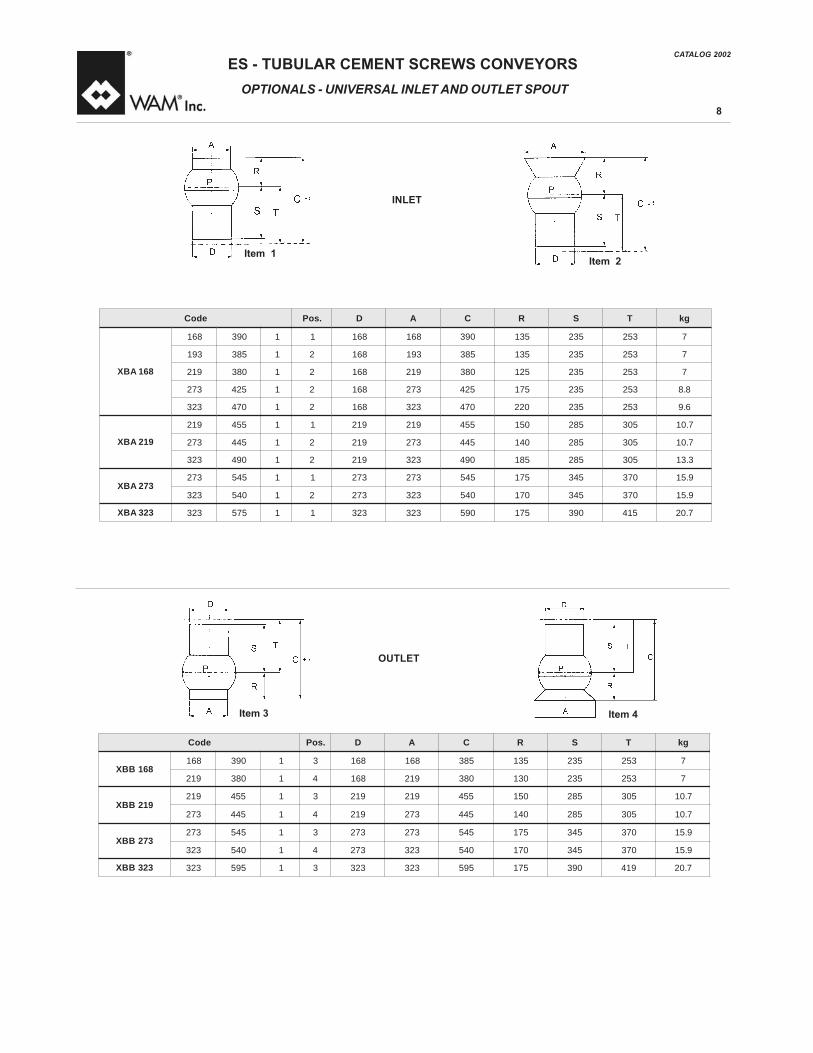
OPTIONALS - UNIVERSAL INLET ANDOUTLET SPOUT
INLET
OUTLET
Item 1
Item 4Item 3
Item 2
edoC .soP D A C R S T gk
861BBX861 093 1 3 861 861 583 531 532 352 7
912 083 1 4 861 912 083 031 532 352 7
912BBX912 554 1 3 912 912 554 051 582 503 7.01
372 544 1 4 912 372 544 041 582 503 7.01
372BBX372 545 1 3 372 372 545 571 543 073 9.51
323 045 1 4 372 323 045 071 543 073 9.51
323BBX 323 595 1 3 323 323 595 571 093 914 7.02
edoC .soP D A C R S T gk
861ABX
861 093 1 1 861 861 093 531 532 352 7
391 583 1 2 861 391 583 531 532 352 7
912 083 1 2 861 912 083 521 532 352 7
372 524 1 2 861 372 524 571 532 352 8.8
323 074 1 2 861 323 074 022 532 352 6.9
912ABX
912 554 1 1 912 912 554 051 582 503 7.01
372 544 1 2 912 372 544 041 582 503 7.01
323 094 1 2 912 323 094 581 582 503 3.31
372ABX372 545 1 1 372 372 545 571 543 073 9.51
323 045 1 2 372 323 045 071 543 073 9.51
323ABX 323 575 1 1 323 323 095 571 093 514 7.02

CATALOG 2002ES - TUBULAR CEMENT SCREWS CONVEYORS
9
MODULARCODEKEY
1st GROUPSTRUCTURE
1234567123456712345671234567123456712345671234567
Inclination
Inlet-outlet length114168 - 273323
Inlet typeA = UniversalC = Circular+ = None or special
Inlet diameter
Inlet height
Outlet type
B = UniversalC = Circular+ = None or speciale
Outlet diameter
Outlet height
mm
mm
mm
mm
cm
mm
degrees
ES ESL ESV
Pipe diameter114 = 4î168 = 6î219 = 8î273 = 10î323 = 12î

CATALOG 2002ES - TUBULAR CEMENT SCREWS CONVEYORS
10
2nd GROUPDRIVE UNIT
1234567123456712345671234567123456712345671234567
Gear reducerM11 - M12 - M15 - M17 - M19 - L19 - L17
Gear ratio05 - 07 - 10
Inst. drive power01 10 - 01 50 - 02 20 - 03 00 - 04 00 - 05 0007 50 - 09 20 - 11 00 - 15 00 - 18 50 - 22 00
Nbr of poles48 = 4/840 = 4
Voltage supply208 V230 V460 V575 V
Cycles50 = 50 Hz60 = 60 Hz++ = non-WAM
Drive positionC = Inlet endT = Outlet end
MODULARCODEKEY

ESES Code
(mm)
ES.114
ES.168
ES.219
ES.273
ES.323
ES.323
Tube ÿ
Nom
.
4î 6î 8î 10î
12î
12î
feet
3-45
3-45
3-45
3-45
3-45
3-23
meters
1-15
1-15
1-15
1-15
1-15 1-7
kW 1.5-4
2.2-7.5
5.5-15
5.5-22
11-22
22-30
HP
2-5.5
3-10
7.5-20
7.5-30
15-30
30-40
Ibs/min
233
1050
2800
4000
6000
7000
ton/hour
7 29 80 115
190
220
MotorRange
StandardFeed
RateCement
LengthRange
Standard
Screw
-Motor
-Gearbox
-Inlet&dischargewithsame
diameterastroughtube
-Motorandgearboxoninletside
Options
-Driveondishargeend
-Heavy-dutyhangerbearings
-Swivelspout-Rangesfrom6î-12î
ontopand/orbottom
ENDBEARING
Fasterinstallation
Lowermaintenance
PortlandCement70lbs/cf
SwiwelSpout-Rangesfrom6î-12îforinletordischarge
SplineDesign
INTERMEDIATE
BEARING
-Engineeredform
inimum
productobstruction
-Lowmaintenance
-Transmitsnonetorque
-Betteraligniment
MODULARCONSTRUCTION
-Easeofshipping
-Pre-assembled
Standardhangerinspection
Shotblasted
Primer/Finishcoat
SPLINED
COUPLING
Fasterinstallation-Lowermaintenance
SWIWELSPOUTADJUSTABLE
INCLINATION
Flexibletolerance-Allowforeasyfieldinstallation
GEARBOX
Heavy-dutyconstruction-Oversized
ï
SCREW
CONVEYORSARE
ESPECIALLYDESIGNEDFOR
CEM
ENTANDFLYASH
ï
CodeBreakdown
ES.(externalÿinmm).(lengthinmeters).(m
otorsize)
Example:ES.219.7.1100=8îdiameter-7meterslong-11.0kW
(15.0Hp)
ï
Average2weeksdelivery
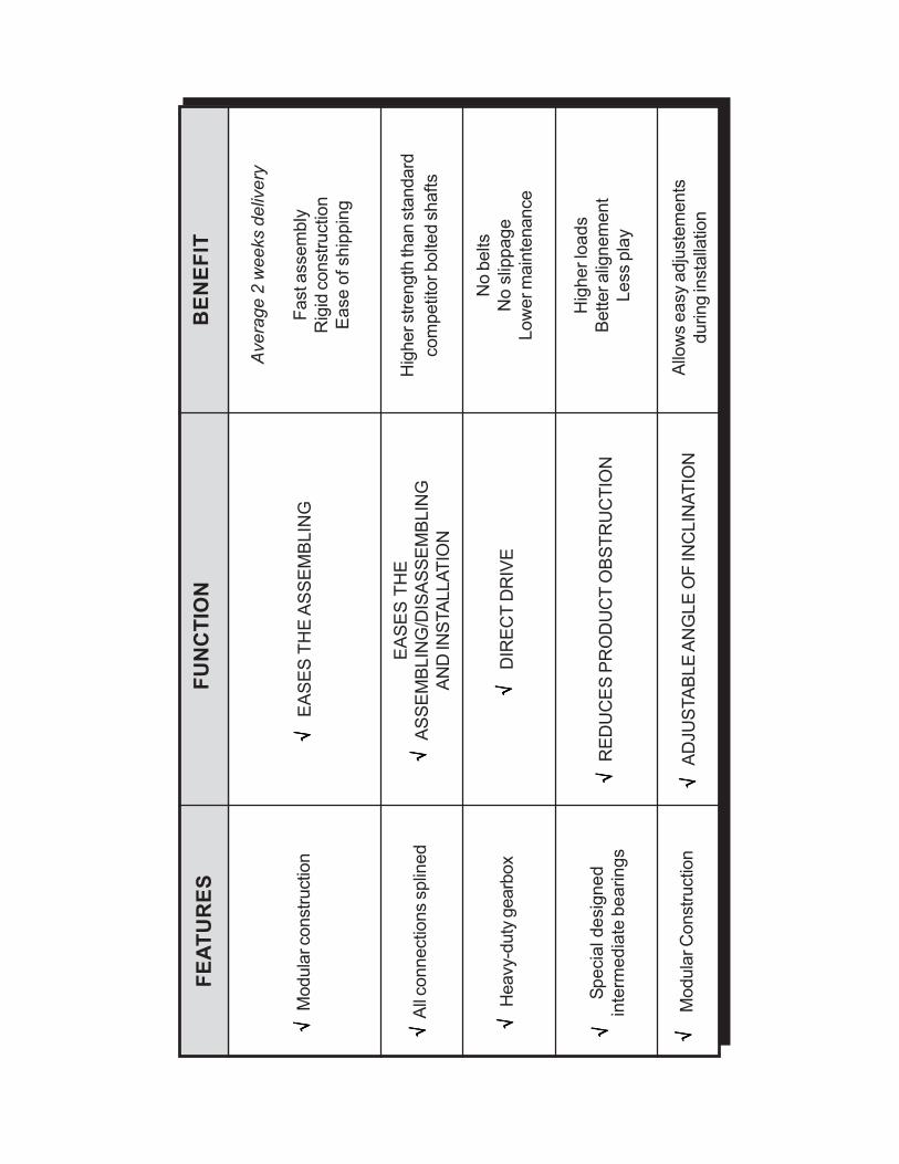
Modularconstruction
EASESTHEASSEMBLING
Average2weeksdelivery
Fastassembly
Rigidconstruction
Easeofshipping
BENEFIT
FUNCTION
FEATURES
Allconnectionssplined
Heavy-dutygearbox
Specialdesigned
intermediatebearings
ModularConstruction
EASESTHE
ASSEMBLING/DISASSEMBLING
ANDINSTALLATION
DIRECTDRIVE
REDUCES
PRODUCTOBSTRUCTION
ADJUSTABLEANGLEOFINCLINATION
Higherstrengththanstandard
competitorboltedshafts
Nobelts
Noslippage
Lowermaintenance
Higherloads
Betteralignement
Lessplay
Allowseasyadjustements
duringinstallation
√√√√ √ √√√√ √ √√√√ √ √√√√ √ √√√√ √
√√√√ √
√√√√ √
√√√√ √
√√√√ √ √√√√ √

CATALOG 2002ES - TUBULAR CEMENT SCREWS CONVEYORS
13
COMPONENTSANDACCESSORIES SECTION Page
Outlet EndBearingXTA.......................................................................................................Inlet EndBearingXTB..........................................................................................................IntermediateBearingXLR...................................................................................................Optional HeavyDutyHangerAssemblyXLY...................................................................Optionals - Flanges /Adjustable Support XJX...............................................................
1415161718

CATALOG 2002ES - TUBULAR CEMENT SCREWS CONVEYORS
14
OUTLETENDBEARINGXTA
X T AA S0 0 E 0 1
ÿ Feeder0 = 1141 = 1682 = 1933 = 2194 = 2735 = 323
ï
ï
edoCNID2845
DØE 1E 2E 3E 4E FØ 1FØ 2FØ
3FK gk gniraeB
Ø °N
10A0SE00ATX 52x82 571 05 45 56 2 841 071 091 8M 4 6 3 SR2-6006
10A1SE00ATX 63x04 5.791 23 5.27 58 3 261 022 052 01M 8 8 7 SR2-8006
10A2SE00ATX 63x04 5.791 23 5.27 58 3 681 022 052 01M 8 8 7 SR2-8006
10A3SE00ATX 63x04 5.791 23 5.27 58 3 012 052 572 01M 8 8 5.7 SR2-8006
10A4SE00ATX 63x04 5.791 23 5.27 58 3 562 503 033 01M 8 8 5.9 SR2-8006
10A5SE00ATX 63x04 5.791 62 5.27 58 4 513 073 504 01M 8 41 51 SR2-8006

CATALOG 2002ES - TUBULAR CEMENT SCREWS CONVEYORS
15
INLETENDBEARINGXTB
edoCINU7936
CØ
NID2845
DØE 1E 2E 3E 4E 5E 6E FØ Ø
1FØ2F
3FK
LxHxGNID5886
gkgniraeB esaerG
Ø °N .dar .xa gk
21B0SE52BTX 52 52x82 052 05 18 45 56 2 2 841 071 091 8M 4 21 54x7x8 6 56006 6011 60.0
21B1SE53BTX 53 63x04 033 55 5.711 5.27 58 2 3 261 022 052 01M 8 41 05x8x01 41 58026 8011 80.0
21B2SE53BTX 53 63x04 033 55 5.711 5.27 58 2 3 681 022 052 01M 8 41 05x8x01 41 58026 8011 80.0
21B3SE53BTX 53 63x04 033 55 5.711 5.27 58 2 3 012 052 572 01M 8 51 05x8x01 5.61 58036 8021 90.0
21B4SE53BTX 53 63x04 033 55 5.711 5.27 58 2 3 562 503 033 01M 8 51 05x8x01 7.91 58036 8021 90.0
21B5SE53BTX 53 63x04 033 55 5.711 5.27 58 2 4 513 073 504 01M 8 51 05x8x01 52 58036 8021 90.0
X T BB SE 1 2
ÿ Feeder0 = 1141 = 1683 = 2194 = 2735 = 323
ï
ï

CATALOG 2002ES - TUBULAR CEMENT SCREWS CONVEYORS
16
edoC ØtfahS
ØredeeF A B C DØ E L
MØNID2845
gK
44T010B820RLX 820 411 45 53 03 01M 8 071 52x82 7.1
44T210B820RLX 820 931 5.66 53 03 01M 01 071 52x82 8.1
44T510B040RLX 040 861 08 55 15 41M 51 542 63x04 5.3
44T710B040RLX 040 391 5.29 55 15 41M 51 542 63x04 9.3
44T020B040RLX 040 912 5.501 55 15 41M 51 542 63x04 3.4
44T520B040RLX 040 372 5.231 55 15 41M 51 542 63x04 5.4
44T030B040RLX 040 323 5.751 55 15 41M 51 542 63x04 5
X L TR B 4 4
ÿ Feeder010 = 114015 = 168017 = 193020 = 219025 = 273030 = 323
ï
ï
028 = ÿ114040 = ÿ168 - 219 - 273 - 323
CAST ALUMINIUM HANGER STRUCTURE WITH INCORPO-RATED SELF-LUBRICATING BUSHThe hanger is made up in two parts to enable dismantling without removing the spiral.
INTERMEDIATEBEARINGXLR

CATALOG 2002ES - TUBULAR CEMENT SCREWS CONVEYORS
17
edoC ØtfahS
ØredeeF A B C Ø
D L MØ2845NID gk
11T510H540YLX 54 861 08 57 26 41M 522 63x04 4
11T710H540YLX 54 391 5.29 57 26 41M 522 63x04 2.4
11T020H540YLX 54 912 5.501 57 26 41M 522 63x04 5.4
11T520H540YLX 54 372 5.231 57 26 41M 522 63x04 7.4
11T030H540YLX 54 323 5.751 57 26 41M 522 63x04 5
OPTIONAL HEAVY DUTY HANGERASSEMBLYXLY

CATALOG 2002ES - TUBULAR CEMENT SCREWS CONVEYORS
18
.giF edoC AØ BØ CØ
G
ssenkcihT
foepyT
SFV
evlaV
gk
°N Ø
1 192FKX 141 081 022 4 5.31 6 001 1
1 103FKX 611 081 022 4 41 6 001 5.1
1 113FKX 861 002 822 4 41 6 051 0.1
1 123FKX 391 052 872 4 41 6 002 7.1
2 133FKX 912 052 872 8 41 6 002 3.1
2 143FKX 372 003 823 8 41 6 052 5.1
2 153FKX 323 053 873 8 41 6 003 7.1
3 163FKX 323 573 044 8 41 6 003 0.4
2 173FKX 753 004 044 8 41 6 053 0.3
2 183FKX 804 074 035 8 41 6 004 0.5
OPTIONALS - FLANGES / ADJUSTABLE SUPPORT XJX
Adjustable supports are strong pipe clamps used for fixing of the feeder to an existing structure and to prevent vibrations and flections.They can be mounted at any point of the pipe section, as they are made up of two half-rings that are bolted together.
Finishing: galvanized
Mounted on framework
Example of application
OPTIONADJUSTABLE SUPPORT
edoC A B C D E gk
1912XJX 912 023 561 503 091 05.21372XJX 372 573 091 553 512 08.21323XJX 323 524 512 504 042 01.3

CATALOG 2002ES - TUBULAR CEMENT SCREWS CONVEYORS
19
OPERATIONANDMAINTENANCE
OPERATIONANDMAINTENANCE Page
Assembly InstructionsWhenUsingWAMÆButterfly Valve....................................Replacement ofHangerBearing...................................................................................OperationandMaintenance............................................................................................Operation andMaintenanceLubrification...................................................................
20212223

CATALOG 2002ES - TUBULAR CEMENT SCREWS CONVEYORS
20
1) The VFS-type valves made of aluminium alloy are not designed to bear the weight of equipment installed below (e.g. screw feeders, beltconveyors, vibratory feeders etc.).
2) To fix the valve, only use stud bolts that are long enough to pass through the upper connecting flange, the valve itself as well as the lowerconnecting flange, forming a sandwich. Screw on the nuts firmly but not excessively. The inside nuts have no weight-bearing function. Theyonly serve to secure the valve when the feeder installed below is stripped down.
3) Apply a thin layer of liquid seal before fitting the valve to the connecting flange.4) Close the valve only when material is flowing.5) Clean the valve regularly with either air or water. This is particularly important if the material handled tends to compact or to solidify due tolonger shutdown periods.
6) Operating temperature < 80 C.7) The material weight resting on the disc must never be greater than its maximum static torque. As it is difficult to calculate this weight exactlydue to varying material properties, as rule of thumb, one may consider there are no problems with bulk densities <1.3 t/m3 in standard hoppersand silos
8) Refer to assembly instructions on WAMÆactuators included in each package.
OPERATIONANDMAINTENANCE
ASSEMBLY INSTRUCTIONSWHEN USINGWAMÆBUTTERFLYVALVE
REPLACEMENTOF SEALS IN DRIVE HEADAND IN ENDBEARINGASSEMBLY
Referring to Fig.1 carry out the following steps:1) Close silo valve.2) Empty screw feeder.3) Disconnect electric motor from mains.4) Open inspection hatches.5) Prevent the inlet screw (D) from sliding out by introducing a plank (A) into the inlet hatch ensuring plank firmly locks in.6) Ensure eyebolt (F) of electric motor is tightly screwed on.7) Fix the lifting device to the eyebolt (F).8) Remove reducer flange bolts and remove gear motor (B).9) Replace seals (C) with new ones.10) Reassemble parts proceed-ing in the opposite way as described.
The same operations apply also if drive unit is at outlet end.And if the sealing of the end bearing has to be substituted
Fig.1

CATALOG 2002ES - TUBULAR CEMENT SCREWS CONVEYORS
21
OPERATIONANDMAINTENANCE
With reference to Fig. 2 carry out the following steps:
1) Open inspection hatch beneath the bearing to be replaced.2) Remove bolts that fasten the two bearing halves.3) Lower bearing half is now free. Remove external hanger bolts and turn upper hanger half until it can be extracted through the hatch.
In addition to Fig.1, as well as to instructions under reference Fig.2 proceed as follows:
4) Carefully loosen plank (A)5) Gently lower inlet spiral (D) until shaft (E) is free.6) Replace shaft (E).
For reassembly proceed the opposite way.
If only the slide bushes must be replaced the above-mentioned steps do not have to be carried out. The half bush may be simply replaced withoutcarrying out the above steps.
REPLACEMENT OF HANGER BEARING
REPLACEMENT OF HANGER BEARING(INCLUDING SHAFT)

CATALOG 2002ES - TUBULAR CEMENT SCREWS CONVEYORS
22
OPERATIONANDMAINTENANCE
TROUBLESHOOTING
Minor problems can be solved without consulting a specialist. Below isa list of the more common problems with their possible causes andremedies.
PROBLEMMotor does not startPOSSIBLE REASONS1) No correct wiring2) Motor failure or failure in the wiring supplyACTION1) Check fuses; if faulty, replace2) Repair or replace part concerned
PROBLEMThe motor starts but then stopsPOSSIBLE REASONS1) lncorrect rotation2) Screw obstruction3) Output rate too high4) Motor burnt out5) Defective bearing or gear re-ducer6) Outlet blockedACTION1) Reverse poles2) Change hanger bearings; if necessary clean whole screw feeder3) Check ampmeter reading and output rate; if both are too high contactour Sales Office.
4) Discover reason and only then replace motor5) Discover reason (see 2) - could be normal wear - replace part con-cerned
6) Free outlet
PROBLEMMotor starts, but screw does not conveyPOSSIBLE REASONS1) Gear pinion or drive shaft sheared2) Incorrect rotation3) Bad outflow of material from silo due to faulty fluidizationACTION1) Discover reason, replace part concerned2) Reverse poles3) Improve outflow of material.
CHECK LIST IN CASEOFSCREWFEEDER TROUBLE
1)General questions Fault descriptiona)Ask plant operator when and under which circumstances feederstops. Does feeder start without problems after long periods ofnon-operation?
b)Do weather conditions negatively influence feeder operation?c) If valve is fitted to feeder outlet check the center line of the valveshaft is parallel with the center line of the feeder, as would befitted in normal circumstances.
Check valve fully opens.Make sure feeder outlet valve is open when feeder starts and it onlycloses when feeder has already stopped.If necessary disconnect valve actuator in open position.
2) Silo checka) Is the silo equipped with a deflecting or bridge breaking cone?b) Does silo include a fluidization system? If so how does it operate?Automatically at intervals while feeder is turned on? Manually foremergency in case of bridging?
c) Is silo cone equipped with a vibrator or knocker? How does it work?3) Electric equipment checka) Is a drop in voltage possible through the contemporary starting ofvarious machines?
b) Is the plant equipped with a generator?c) Check main supply of motor.d) Check electric motor is correctly wired and make sure wires aretightly fastened.
e) Check adjustment of thermal cutout in the control panel and com-pare with data on the motor plate.
f ) Check motor rotation.g) Read amperage with feeder running empty, then with filled feederstarting, as well as with full feeder running.
h) Check cross section of mains cables are suitable for the installeddrive power.
4)Mechanical parts checka) Is breather plug of gear reducer functioning?b) Check outlet is free of crusts. Describe outlet (e.g. vertical or angu-lar).
c) Check weigh hopper vent is functioning correctly and check cor-rect dimensioning of same.
5) Feeder checka) Are feeder parts correctly assembled? Do all inspection hatchespoint downwards?
b) Does feeder bend? Stretch a string. If necessary additional sup-ports must be fitted (every 3 to 5 metres to feet).
c) Shut silo outlet valve. Empty feeder.d) Open inspection hatches. Check intermediate bearings are okayand correctly mounted.
e) Turn feeder by hand using a spanner on the outlet end bearing shaft.If you don't feel any resistance and don't hear any grinding noise itis most certain that feeder is mechanically sound.
f) Shut inspection hatches. Start feeder. Read amperage, voltage, cy-cles and screw r.p.m. with empty feeder running. Compare amme-ter reading with motor plate data.
h) Repeat starting procedure with feeder at full load and read amper-age, voltage and cycles.
6)Material checka) Material description?b) Bulk density? (kg/dm3)c) Particle size? (μm/mm)d) Humidity? (%)e) Flowability? (make material slide down a metal plate by varying theangle from low to steep)
f) Compressive material? (can you make a ìsnowballî?)g) Abrasive material? (does it hurt when rubbing it between yourfingers?)
CATALOG 2002ES - TUBULAR CEMENT SCREWS CONVEYORS
23
OPERATIONANDMAINTENANCELUBRIFICATION
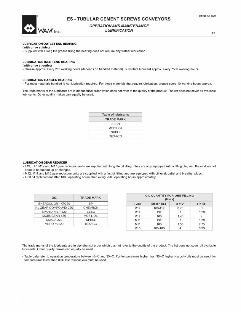
LUBRICATIONOUTLETENDBEARING(with drive at inlet)- Supplied with a long life grease filling the bearing does not require any further lubrication.
LUBRICATION INLET END BEARING(with drive at outlet)- Grease approx. every 200 working hours (depends on handled material). Substitute lubricant approx. every 7500 working hours.
LUBRICATION HANGER BEARING- For most materials handled is not lubrication required. For those materials that require lubrication, grease every 10 working hours approx.
The trade marks of the lubricants are in alphabetical order which does not refer to the quality of the product. The list does not cover all availablelubricants. Other quality makes can equally be used.
LUBRICATIONGEARREDUCER- L19, L17, M19 and M17 gear reduction units are supplied with long life oil filling. They are only equipped with a filling plug and the oil does notneed to be topped up or changed.- M12, M11 and M15 gear reduction units are supplied with a first oil filling and are equipped with oil level, outlet and breather plugs.- First oil replacement after 1000 operating hours, then every 2500 operating hours approximately.
The trade marks of the lubricants are in alphabetical order which dos not refer to the quality of the product. The list does not cover all availablelubricants. Other quality makes can equally be used.
- Table data refer to operation temperature between 0 C and 35 C. For temperatures higher than 35 C higher viscosity oils must be used, fortemperatures lower than 0 C less viscous oils must be used.
GNILLIFENOROFYTITNAUQLIO
)sretil(
epyT ezisrotoM °0=a °54=a
21M 211-001 57.0 1
21M 231 1 05.1
21M 061 04.1 /
11M 231 1 05.1
11M 061 05.1 57.2
51M 081-061 4 05.6
stnacirbulfoelbaTKRAMEDART
OSSELIOLIBOM
LLEHSOCAXET
LIO KRAMEDART
022PX-RGLOGRENE PB022DNUOPMOCRAEGLN NORVEHC
022PENATRAPS OSSE036RAEGLIBOM LIOLIBOM
022ALAMO LLEHS022APOREM OCAXET

CATALOG 2002ES - TUBULAR CEMENT SCREWS CONVEYORS
24
SPARE PARTS
SPARE PARTS Page
SpareParts..............................................................................................................................Tubular Screw Feeder Series Es With Three Hanger Bearings SteelFabricatedParts......................................................................................................................Tubular Screw Feeder Series Es Steel Fabricated Parts.............................................Outlet BearingAssemblySeriesXTA................................................................................Outlet BearingAssemblySeriesXTB...............................................................................HangerBearingSeriesXLR................................................................................................GearBoxM17..........................................................................................................................GearBoxM12..........................................................................................................................GearBoxM11..........................................................................................................................GearBoxM15..........................................................................................................................CompleteMotor......................................................................................................................Safety........................................................................................................................................
26
27 < 282930313233 < 3536 < 3738 < 3940 < 414243

CATALOG 2002ES - TUBULAR CEMENT SCREWS CONVEYORS
25
SPARE PARTS
ADDRESS OF DEALER OR LOCAL SERVICE POINT
IDENTIFICATION
Refer to other code and/or to the serial number in the acknowledgment of order in the invoice and on the packaging to identify the equipment.
1) Order code.2) Serial number.
EXAMPLE OF SERIAL NUMBER
CONTRAINDICATIONS TO USElf the customer observes the normal caution (typical of this kind of machines) together with the indications contained in this manual, work is safe.These machines are NOT suitable for handling of foodstuff.
The machine must not be started before the machine itself, as well as the plant it is going to be installed in, have been declared in conformity withthe European Directive 14/06/1982 (89/392/EEC).
It is the plant designerís / plant fitterís responsibility to design and install all necessary protection in order to avoid that breaking and/or yieldingof the quipment or of parts of it might damage people and/or parts of the plant (e.g. adequate protection against falling down of the motor etc.).For the handling of products with the following characteristics the plant designer or fitter must provide for appropriate protection devices: danger-ous, harmful when touched and/or inhaled, inflammable, explosive, infective.
12
ORDERING SPARE PARTS
A) Steel fabricated parts and bearing assembliesPlease indicate serial n . of the conveyor applied on each trough section, as well as page and item no. in this catalogue of the part concerned.Also indicate the required quantity of parts taking into consideration the minimum supply given in the price Iist.
B) Gear reduction units and electric motorsInstead of the screw serial n . indicate serial n . of gear reduction unit or of the electric motor and add information requested in paragraph A).Parts not included in price Iist cannot be supplied.These are:1) Standard parts if not included in kits2) Item numbers in brackets, i.e. single parts included in kits.
Check minimum supply before making an order. General Supply Conditions are valid.

CATALOG 2002ES - TUBULAR CEMENT SCREWS CONVEYORS
26
SPARE PARTS
TUBULAR SCREW FEEDER SERIES ES WITH THREE HANGER BEARINGS STEEL FABRICATED PARTS

CATALOG 2002ES - TUBULAR CEMENT SCREWS CONVEYORS
27
SPARE PARTS
TUBULAR SCREW FEEDER SERIES ES WITH THREE HANGER BEARINGS STEEL FABRICATED PARTS

CATALOG 2002ES - TUBULAR CEMENT SCREWS CONVEYORS
28
TUBULAR SCREW FEEDER SERIES ES STEEL FABRICATED PARTS
metI ytitnauQ sdradnatS NOITPIRCSED
1.A X+1 931-411SE tiKhctahnoitcepsnI
2.A X+1 391-861SE tikhctahnoitcepsnI
3.A X+1 323-372-912SE tiKhctahnoitcepsnI
2 1 855NID55x61M tloblanogaxeH
3 rebmunlaireS
A4 )eceip1(sepiplanretxE
B4 epiptelnilanretxE
C4 epipteltuolanretxE
D4 epipetaidemretnilanretxE
A5 )eceip1(wercs.lpC
B5 wercstelni.lpC
C5 wercsteltuo.lpC
D5 wercsetaidemretni.lpC
1.6 X8+8 8976NID8Ø )931-411SE(rehsaW
2.6 X61+61 8976NID01Ø )323...861SE(rehsaW
1.7 8 855NID52x8M )931-411SE(tlob.nogaxeH
2.7 61 855NID03x01M )323...861SE(tlob.nogaxeH
1.8 X4 855NID53x8M )931-411SE(tlob.nogaxeH
2.8 X8 855NID04x01M )372...861SE(tlob.nogaxeH
3.8 X8 855NID05x01M )323SE(tlob.nogaxeH
1.9 X4 855NID8M )931-411SE(tlob.nogaxeH
2.9 X8 855NID8M )323...861SE(tlob.nogaxeH
SPARE PARTS

CATALOG 2002ES - TUBULAR CEMENT SCREWS CONVEYORS
29
SPARE PARTS
OUTLET BEARINGASSEMBLYSERIES XTA
retemaiD rebmuNtraP
"4-mm411 1OA.0SE.00.ATX
"6-mm861 1OA.1SE.00.ATX
"8-mm912 1OA.3SE.00.ATX
"01-mm372 1OA.4SE.00.ATX
"21-mm323 1OA.5SE.00.ATX

CATALOG 2002ES - TUBULAR CEMENT SCREWS CONVEYORS
30
SPARE PARTS
OUTLET BEARINGASSEMBLYSERIES XTB
Only with drive unit mounted at outled end !
retemaiD rebmuNtraP
"4-mm411 21B.0SE.52.BTX
"6-mm861 21B.1SE.53.BTX
"8-mm912 21B.3SE.53.BTX
"01-mm372 21B.4SE.53.BTX
"21-mm323 21B.5SE.53.BTX

CATALOG 2002ES - TUBULAR CEMENT SCREWS CONVEYORS
31
SPARE PARTS
HANGERBEARINGSERIESXLR
retemaiD rebmuNtraP
"4-mm411 44T010B820.RLX
"6-mm861 44T510B040.RLX
"8-mm912 44T020B040.RLX
"01-mm372 44T520B040.RLX
"21-mm323 44T030B040.RLX

CATALOG 2002ES - TUBULAR CEMENT SCREWS CONVEYORS
32
GEAR REDUCTION HEAD SERIES M17 with incorporated end bearing
- for IEC and NEMA motors: 0.55 kW - 0.75 kW - 1.1 kW - 1.5 kW - 2.2 kW - 3 kW - 4 kW - 5.5 kW
SPARE PARTSGEAR BOX M17

CATALOG 2002ES - TUBULAR CEMENT SCREWS CONVEYORS
33
GEAR REDUCTION HEAD SERIES M17 with incorporated end bearing - for IEC and NEMA motors
metI ytitnauQ sdradnatS NOITPIRCSED1 1 OSEtfahSb1 1 3-2-1SEtfahSa2 1 )09-08(dnerotomgnisaCb2 1 )211-001(dnerotomgnisaCc2 1 )231(dnerotomgnisaCa3 1 OSEdnewercsgnisaCb3 1 1SEdnewercsgnisaCc3 1 2SEdnewercsgnisaCd3 1 )231(1SEdnewercsgnisaCe3 1 )231(2SEdnewercsgnisaCf3 1 )231(3SEdnewercsgnisaCaA 1 )09-08(5:1tiKraeG)4( 1 tfahsnoiniP)5( 1 leehwgoC)6( 1 5886NID52x7x8 yeKlellaraPbA 1 )211(5:1tiKraeG)4( 1 tfahsnoiniP)5( 1 leehwgoC)6( 1 5886NID02x7x8 yeKlellaraPcA 1 )231(5:1tiKraeG)4( 1 tfahsnoiniP)5( 1 leehwgoC)6( 1 5886NID02x7x8 yeKlellaraPdA 1 )09-08(7:1tikraeG)4( 1 tfahsnoiniP)5( 1 leehwgoC)6( 1 5886NID02x7x8 yeKlellaraPeA 1 )211(7:1tiKraeG)4( 1 tfahsnoiniP)5( 1 leehwgoC)6( 1 5886NID02x7x8 yeKlellaraP
metI ytitnauQ sdradnatS NOITPIRCSEDfA 1 )09-08(01/1tiKraeG)4( 1 tfahsnoiniP)5( 1 leehwgoC)6( 1 5886NID52x7x8 yeKlellaraPgA 1 )211(01/1tiKraeG)4( 1 tfahsnoiniP)5( 1 leehwgoC)6( 1 5886NID52x7x8 yeKlellaraPaB 1 )09-08(OSEtiKlaeslanretnI)8( 1 BN-0673NID laestfahS)9( 1 BN-0673NID laestfahSbB 1 )211-001(OSEtiKlaeslanretnI)8( 1 BN-0673NID laestfahS)9( 1 BN-0673NID laestfahScB 1 )211-001(OSEtiKlaeslanretnI)8( 1 BN-0673NID laestfahS)9( 1 BN-0673NID laestfahSdB 1 )211-001(2-1SEtiKlaeslanretnI)8( 1 BN-0673NID laestfahS)9( 1 BN-0673NID laestfahSeB 1 )231(3-2-1SEtiKlaeslanretnI)8( 1 BN-0673NID laestfahS)9( 1 BN-0673NID laestfahS
1 )09-08(OSEtiKgniraeB)21( 1 526NID gniraeB)31( 2 117NID gniraeB)41( 1 526NID gniraeB
bC 1 )211-001(OSEtiKgniraeB)21( 1 526NID gniraeB)31( 2 117NID gniraeB)41( 526NID gniraeB
SPARE PARTSGEAR BOX M17
M17 . . . . . ES .
0: ÿ 114-1391: ÿ 1682: ÿ 1933: ÿ 219
05: Ratio1:507: ì 1:710: ì 1:10
080 100-112090 132
Code
145 - 182184
NEMAIEC

CATALOG 2002ES - TUBULAR CEMENT SCREWS CONVEYORS
34
metI ytitnauQ sdradnatS NOITPIRCSEDdC 1 )09-08(2-1SEtiKgniraeB)21( 1 526NID gniraeB)31( 1 117NID gniraeB)51( 1 526NID gniraeB)71( 1 526NID gniraeB
eC 1 )211-001(2-1SEtiKgniraeB)21( 1 526NID gniraeB)31( 1 117NID gniraeB)51( 1 526NID gniraeB)71( 1 526NID gniraeB
fC 1 )231(3-2-1SEtiKgniraeB)21( 1 526NID gniraeB)31( 1 117NID gniraeB)51( 1 526NID gniraeB)71( 1 526NID gniraeB
42 1 "8/3 gulpliOa91 2 274NID86Ø )09-08(erobrofgnirgniniateRb91 2 274NID08Ø )211-001(erobrofgnirgniniateRc91 2 274NID59Ø )231(erobrofgnirgniniateRa12 2 174NID04Ø )09-08(tfahsrofgnirgniniateRb12 2 174NID05Ø )211-001(tfahsrofgnirgniniateRc12 2 174NID66Ø )231(tfahsrofgnirgniniateR
82 1 2SE-1SErecapS92 1 889NID1x24x03Ø gnirgniniateRa03 4 339NID52x01M )09-08(tloblanogaxeHb03 4 339NID03x21M )231-211-001(tloblanogaxeHa13 4 A521NID01Ø )09-08(rehsawdeleveBb13 4 A521NID21Ø )231-211-001(rehsawdeleveBa23 4 0897NID01Ø )09-08(rehsawcitsalEb23 4 0897NID21Ø )231-211-001(rehsawcitsalEa33 9 219NID03x8M )09-08(tlobtekcoslanogaxeHb33 9 219NID57x8M )231-211-001(tlobtekcoslanogaxeH
43 9 A521NID8Ø rehsawdeleveB53 9 0897NID8Ø rehsawcitsalE
7 1 )08(eveelsretpadA11 1 )08(yeKlellaraPa63 1 0SEtinugnilaestfahSb63 1 3-2-1SEtinugnilaestfahS
GEAR REDUCTION HEAD SERIES M17 with incorporated end bearing - for IEC and NEMA motors
M17 . . . . . ES .
0: ÿ 114-1391: ÿ 1682: ÿ 1933: ÿ 219
05: Ratio1:507: ì 1:710: ì 1:10
080 100-112090 132
Code
SPARE PARTSGEAR BOX M17
145 - 182184
NEMAIEC

CATALOG 2002ES - TUBULAR CEMENT SCREWS CONVEYORS
35
GEAR REDUCTION HEAD SERIES M12 with incorporated end bearing
- for IEC and NEMA motors: 3 kW - 4 kW - 5.5 kW - 7.5 kW - 9.2 kW - 11 kW
SPARE PARTSGEAR BOX M12

CATALOG 2002ES - TUBULAR CEMENT SCREWS CONVEYORS
36
GEAR REDUCTION HEAD SERIES M12 with incorporated end bearing - for IEC and NEMA motors
metI ytitnauQ sdradnatS NOITPIRCSED1 1 tfahSa2 1 )211-001(dnerotomgnisaCb2 1 )231(dnerotomgnisaCc2 1 )061(dnerotomgnisaCa3 1 1SEdnewercsgnisaCb3 1 2SEwercsgnisaCc3 1 5SE-3SEdnewercsgnisaCd3 1 4SEdnewercsgnisaCaA 1 )211(5/1tiKraeG)4( 1 tfahsnoiniP)5( 1 leehwgoC)6( 1 yeKlellaraPbA 1 )231(5/1tiKraeG)4( 1 tfahsnoiniP)5( 1 leehwgoC)6( 1 yeKlellaraPcA 1 )061(5/1tiKraeG)4( 1 tfahsnoiniP)5( 1 leehwgoC)6( 1 yeKlellaraPdA 1 )211(6/1tiKraeG)4( 1 tfahsnoiniP)5( 1 leehwgoC)6( 1 yeKlellaraPeA 1 )231(6/1tiKraeG)4( 1 tfahsnoiniP)5( 1 leehwgoC)6( 1 yeKlellaraP
metI ytitnauQ sdradnatS NOITPIRCSEDfA 1 )231(7/1tiKraeG)4( 1 tfahsnoiniP)5( 1 leehwgoC)6( 1 yeKlellaraPhA 1 )231(7/1tiKraeG)4( 1 tfahsnoiniP)5( 1 leehwgoC)6( 1 yeKlellaraPiA 1 )211(01/1tiKraeG)4( 1 tfahsnoiniP)5( 1 leehwgoC)6( 1 yeKlellaraPlA 1 )231(01/1tiKraeG)4( 1 tfahsnoiniP)5( 1 leehwgoC)6( 1 yeKlellaraPaB 1 )211(tiKlaeslanretnI)8( 1 BN-0673NID laestfahS)9( 1 BN-0673NID laestfahSbB 1 )061-231(tiKlaeslanretnI)8( 1 BN-0673NID laestfahS)9( 1 BN-0673NID laestfahsaC 1 )211-011(tiKgniraeB)21( 1 526NID gniraeB)31( 1 117NID gniraeB)41( 1 526NID gniraeB
bC 1 )061-231(tiKgniraeB)21( 1 526NID gniraeB)31( 1 117NID gniraeB)41( 1 526NID gniraeB
metI ytitnauQ sdradnatS NOITPIRCSEDE 1 tiKgulpliO
)32( 1 "8/3 gulpteltuoliO)42( 1 "8/3 gulprehtaerB)52( 1 "8/3 gulplevelliOa91 2 274NID08Ø 211-011erobrofgnirgniniateRb91 2 274NID59Ø 061-231erobrofgnirgniniateRa12 2 174NID05Ø 211-011tfahsrofgnirgniniateRb12 2 174NID06Ø 061-231tfahsrofgnirgniniateR
72 2 recapS03 4 339NID03x21M tloblanogaxeH13 4 A521NID21Ø rehsawdeleveB23 4 0897NID21Ø rehsawcitsalE33 9 219NID57x8M tlobtekcoslanogaxeH43 9 A521NID8Ø rehsawdeleveB53 9 0897NID8Ø rehsawcitsalE54 1 egnalF64 8 339NID53x01M tloblanogaxeH74 8 A521NID01Ø rehsawdeleveB84 8 0897NID01Ø rehsawcitsalE05 1 tinugnilaestfahS
SPARE PARTSGEAR BOX M12
0: ÿ 114-1391: ÿ 1682: ÿ 1933: ÿ 2194: ÿ 2735: ÿ 323
M12 . . . . . ES .
05: Ratio1:507: ì 1:710: ì 1:10
100-112132160
Code
184 - 213215
NEMAIEC

CATALOG 2002ES - TUBULAR CEMENT SCREWS CONVEYORS
37
GEAR REDUCTION HEAD SERIES M11 with incorporated end bearing
- for IEC and NEMA motors: 5.5 kW - 7.5 kW - 9.2 kW - 11 kW - 15 kW
SPARE PARTSGEAR BOX M11

CATALOG 2002ES - TUBULAR CEMENT SCREWS CONVEYORS
38
metI ytitnauQ sdradnatS NOITPIRCSED1 1 tfahSb2 1 )231(dnerotomgnisaCc2 1 )061(dnerotomgnisaCa3 1 1SEdnewercsgnisaCb3 1 2SEdnewercsgnisaCc3 1 5SE-3SEdnewercsgnisaCd3 1 4SEwercsgnisaCbA 1 )061(5/1tiKraeG)4( 1 tfahsnoiniP)5( 1 leehwgoC)6( 1 5886NID53x8x21 yeKlellaraPcA 1 )231(6/1tiKraeG)4( 1 tfahsnoiniP)5( 1 leehwgoC)6( 1 5886NID53x8x21 yeKlellaraPdA 1 )061(6/1tiKraeG)4( 1 tfahsnoiniP)5( 1 leehwgoC)6( 1 5886NID53x8x21 yeKlellaraPeA 1 )231(7/1tiKraeG)4( 1 tfahsnoiniP)5( 1 leehwgoC)6( 1 5886NID53x8x21 yeKlellaraPfA 1 )061(7/1tiKraeG)4( 1 tfahsnoiniP)5( 1 leehwgoC)6( 1 5886NID53x8x21 yeKlellaraP
GEAR REDUCTION HEAD SERIES M11 with incorporated end bearing - for IEC and NEMA motors
metI ytitnauQ sdradnatS NOITPIRCSEDgA 1 )231(01/1tiKraeG)4( 1 tfahsnoiniP)5( 1 leehwgoC)6( 1 yeKlellaraPhA 1 )061(01/1tiKraeG)4( 1 tfahsnoiniP)5( 1 leehwgoC)6( 1 yeKlellaraP
B 1 tiKslaeslanretnI)4( 1 BN-0673NID laestfahS)5( 1 BN-0673NID laestfahS
C 1 tiKgniraeB)21( 1 526NID gniraeB)31( 1 117NID gniraeB)41( 2 526NID gniraeB
E 1 tiKsgulpliO)32( 1 "8/3 gulpteltuoliO)42( 1 "8/3 gulprehtaerB)52( 1 "8/3 gulplevelliO
81 1 274NID59Ø erobrofgnirgniniateR02 2 174NID06Ø tfahsrofgnirgniniateR72 2 recapS03 4 339NID03x21M tloblanogaxeH13 4 A521NID21Ø rehsawdeleveB23 4 0897NID21Ø rehsawcitsalE33 9 219NID03x8M tlobtekcos.xeH43 9 A521NID8M rehsawdeleveB53 9 0897NID8M rehsawcitsalE54 1 egnalF64 8 339NID53x01M tloblanogaxeH74 8 A521NID01Ø rehsawdeleveB84 8 0897NID01Ø rehsawcitsalE05 1 tinugnilaestfahS
SPARE PARTSGEAR BOX M11
1: ÿ 1682: ÿ 1933: ÿ 2194: ÿ 2735: ÿ 323
M11 . . . . . ES .
05: Ratio1:507: ì 1:710: ì 1:10
132 - 160
Code
254 - 256NEMAIEC

CATALOG 2002ES - TUBULAR CEMENT SCREWS CONVEYORS
39
GEAR REDUCTION HEAD SERIES M15 with incorporated end bearing
- for IEC and NEMA motors: 11 kW - 15 kW - 18.5 kW - 22 kW - 30 kW
SPARE PARTSGEAR BOX M15

CATALOG 2002ES - TUBULAR CEMENT SCREWS CONVEYORS
40
GEAR REDUCTION HEAD SERIES M15 with incorporated end bearing - for IEC and NEMA motors
metI ytitnauQ sdradnatS NOITPIRCSED1 1 tfahSb2 1 )081-061(dnerotomgnisaCc2 1 )002(dnerotomgnisaCa3 1 5SE-3SEdnewercsgnisaCb3 1 4SEwercsgnisaCaA 1 )061(5/1tiKraeG)4( 1 tfahsnoiniP)5( 1 leehwgoC)6( 1 5886NID04x9x41 yeKlellaraPbA 1 )081(5/1tiKraeG)4( 1 tfahsnoiniP)5( 1 leehwgoC)6( 1 5886NID04x9x41 yeKlellaraPcA 1 )061(6/1tiKraeG)4( 1 tfahsnoiniP)5( 1 leehwgoC)6( 1 5886NID04x9x41 yeKlellaraPdA 1 )081(6/1tiKraeG)4( 1 tfahsnoiniP)5( 1 leehwgoC)6( 1 5886NID04x9x41 yeKlellaraPeA 1 )061(7/1tikraeG)4( 1 tfahsnoiniP)5( 1 leehwgoC)6( 1 5886NID04x9x41 yeKlellaraPfA 1 )081(7/1tiKraeG)4( 1 tfahsnoiniP)5( 1 leehwgoC)6( 1 5886NID04x9x41 lellaraP
metI ytitnauQ sdradnatS NOITPIRCSEDgA 1 )002(7/1tiKraeG)4( 1 tfahsnoiniP)5( 1 leehwgoC)6( 1 5886NID04x9x41 yeKlellaraPhA 1 )061(01/1tikraeG)4( 1 tfahsnoiniP)5( 1 leehwgoC)6( 1 5886NID04x9x41 yeKlellaraPiA 1 )081(01/1tikraeG)4( 1 tfahsnoiniP)5( 1 leehwgoC)6( 1 5886NID04x9x41 yeklellaraPlA 1 )002(01/1tiKraeG)4( 1 tfahsnoiniP)5( 1 leehwgoC)6( 1 5886NID04x9x41 yeKlellaraPaB 1 )081-061(tiKlaeslanretnI)8( 1 BN-0673NID laestfahS)9( 1 BN-0673NID laestfahSbB 1 )002(tiKlaeslanretnI)8( 1 BN-0673NID laestfahS)9( 1 BN-0673NID laestfahSaC 1 )081-061(tiKgniraeB)21( 1 526NID gniraeB)31( 1 117NID gniraeB)51( 1 526NID gniraeB)71( 1 526NID gniraeB
bC 1 )002(tiKgniraeB)21( 1 526NID gniraeB)31( 1 117NID gniraeB)51( 1 526NID gniraeB)71( 1 526NID gniraeB
metI ytitnauQ sdradnatS NOITPIRCSEDE 1 tiKgulpliO
)32( 1 "8/3 gulpteltuolIO)42( 1 "8/3 gulprehtaerB)52( 1 "8/3 gulplevelliOa91 2 274NID011Ø )081-061(erobrofgnirgniniateRb91 2 274NID521Ø )002(erobrofnirgniniateRa02 1 174NID07Ø )081-061(tfahSrofgnirgniniateRb02 1 174NID08Ø )002(tfahsrofgnirgniniateR
82 1 recapS92 1 recapS03 4 339NID04x61M tloblanogaxeH13 4 A521NID61Ø rehsawdeleveB23 4 0897NID61Ø rehsawcitsalE33 41 219NID57x01M tlobtekcoslanogaxeH43 41 A521NID01Ø rehsaWdeleveB53 41 0897NID01Ø rehsawcitsalE54 1 egnalF64 8 339NID53x01M tloblanogaxeH74 8 A521NID01Ø rehsawdeleveB84 8 0897NIDS01Ø rehsawcitsalE05 1 tinugnilaestfahS
SPARE PARTSGEAR BOX M15
3: ÿ 2194: ÿ 2735: ÿ 323
M15 . . . . . ES .
05: Ratio1:507: ì 1:710: ì 1:10
180200
Code
284 - 286324
NEMAIEC

CATALOG 2002ES - TUBULAR CEMENT SCREWS CONVEYORS
41
Code M . . . . . . 0 4 . . 54 = CLASS.F. IP55
metI ytitnauQ sdradnatS NOITPIRCSED
1 1 draugnaF
2 1 naF
egnalfraeR
gniraebnaF
gnisaC
rotatS
rotoR
gniraebtnorF
egnalftnorF
01 1 xoblanimreT
SPARE PARTS
COMPLETE MOTOR
12
ï
ï
W = 208 - 230 / 460V 60HzQ = 575V 60HzE = 220/380V 50Hz
NEMA
143145182-184213215-254256282
IEC
0900M0900L100LR100LH1120M1320S1320M1320L1600M1600L1800M
kW
1.11.52.23.04.05.57.59.211.015.018.5
Poles020406
3600 RPM1800RPM1200RPM
CATALOG 2002ES - TUBULAR CEMENT SCREWS CONVEYORS
42
SAFETY
Safety must be considered a basic factor inmachinery operation at all times. Most acci-dents are the result of carelessness or negli-gence. The following safety instructions are basicguidelines and should be considered as mini-mum provisions. Additional information shallbe obtained by the purchaser from other sourc-es, including the American Society of Mechan-ical Engineers, Standard ANSI B20.1, StandardANSI B15.1, Standard ANSI A12.1 StandardANSI MH4.7 and Standard ANSI Z244.WAM, Inc. does not install equipment, conse-
quently it is the responsibility of the contractor,installer, owner and user to install, maintainand operate the conveyor, components andassemblies in such a manner as to comply withthe William-Steiger Occupational Safety andHealth Act and with all state and local laws andordinances and the American National Stan-dard Institute (ANSI) safety code.In order to avoid an unsafe or hazardous con-dition, the assemblies or parts must be installedand operated in accordance with the followingminimum provisions.1. Conveyors, and all other rotating and vibrat-ing equipment (hereafter referred to asequipment) shall not be operated unless allcovers and/or guards for the equipment anddrive unit are in place. If the equipment is tobe opened for inspection cleaning, mainte-nance or observation, the electric power tothe motor driving the conveyor must beLOCKED OUT and TAGGED OUT in such amanner that the equipment cannot be re-started by anyone; however remote from thearea, until equipment cover or guards anddrive guards have been properly replaced.
2. If the equipment must have an open housingas a condition of its use and application, theentire equipment is then to be guarded by arailing or fence in accordance with ANSI stan-dard B20.1-1993, with special attention giv-en to section 6.12.
3. Feed openings for shovel, front loaders orother manual or mechanical equipment shallbe constructed in such a way that the equip-ment opening is covered by a grating. If thenature of the material is such that a gratingcannot be used, then the exposed
1. section of the equipment is to be guarded bya railing or fence and there shall be a warn-ing sign posted.
2. Do not attempt any maintenance or repairsof the equipment until power has beenLOCKED OUT and TAGGED OUT.
3. Control stored energy: Use safety blocks be-tween dangerous parts that could move andinjure. Always operate conveyor in accor-dance with these instructions and those con-tained on the caution labels affixed to theequipment.
4. Do not place hands or feet in the equipment.5. Never walk on equipment covers, grating orguards.
6. Do not use equipment for any purpose otherthan that for which it was intended.
7. Do not poke or prod material into the equip-ment with a bar or stick inserted through theopenings.
8. Keep area around equipment drive and con-trol station free of debris and obstacles.
9. Always regulate the feeding of material intothe unit at a uniform and continuous rate.
10.Do not attempt to clear jammed equipmentuntil power has been LOCKED OUT andTAGGED OUT.
11.Do not attempt field modification of equip-ment or components.
12.Equipment is not normally manufactured ordesigned to handle materials that are haz-ardous to personnel. These materials whichare hazardous include those that are explo-sive, flammable, toxic, or otherwise danger-ous to personnel. Equipment may be de-signed to handle these materials. Equipmentis not manufactured or designed to complywith local, state or federal codes for unfiredpressure vessels. If hazardous materials areto be conveyed or if the equipment is to besubjected to internal or external pressure,WAM, Inc. should be consulted prior to anymodifications.WAM, Inc. insists that disconnecting and lock-ing out and tagging out the power to the motordriving the unit provides this only real protec-tion against injury. Secondary safety devicesare available; however, the decision as to theirneed and the type required must be made
by the owner-assembler as we have no informa-tion regarding plant wiring, plant environment,the Interlocking of the equpment with otherequipment, extent of plant automation, etc.Other devices should not be used as a substi-tute for locking out the power prior to removingguards or covers. We caution that use of thesecondary devices may cause employees to de-velop a false sense of security and fail to lockout power before removing covers or guards.This could result in a serious injury should thesecondary device fail or malfunction.There are many kinds of electrical devices for
interlocking of equipment and equipment sys-tems such that if one item of equipment in asystem or process is stopped other equipmentfeeding it, or following it can also be automat-ically stopped.Electrical controls, machinery guards, railings,
walkways, arrangement of installation, trainingof personnel, etc. are necessary ingredients fora safe working place. It is the responsibility ofthe contractor, installer, owner and user to sup-plement the materials and services furnishedwith these necessary items to make the equip-ment installation comply with the law and ac-cepted standards.Equipment inlet and discharge openings are
designed to connect to other equipment ormachinery so that the flow of material into andout of the equipment is completely enclosed.One or more caution signs as illustrated be-
low are attached to equipment housings andequipment covers. Please order replacementcaution labels should the labels attached tothis equipment become illegible. Use Convey-or Equipment Manufacturers Association(CEMA) ìSafety Label Brochure and PlacementGuidelinesî (#201). CEMA can be contactedat: : www.cemanet.org , or may be written to at::
CEMA6724 Lone Oak Blvd.Naples, FL 34109
WAM, Inc. also provides this information toour customers free of charge when requested.The label shown below has been reduced in
size. The actual size is printed next to the la-bel. For more detailed instructions and infor-mation please request a free copy of our ìScrewConveyor Safety, Installation, Operation, Main-tenance Instructions.î
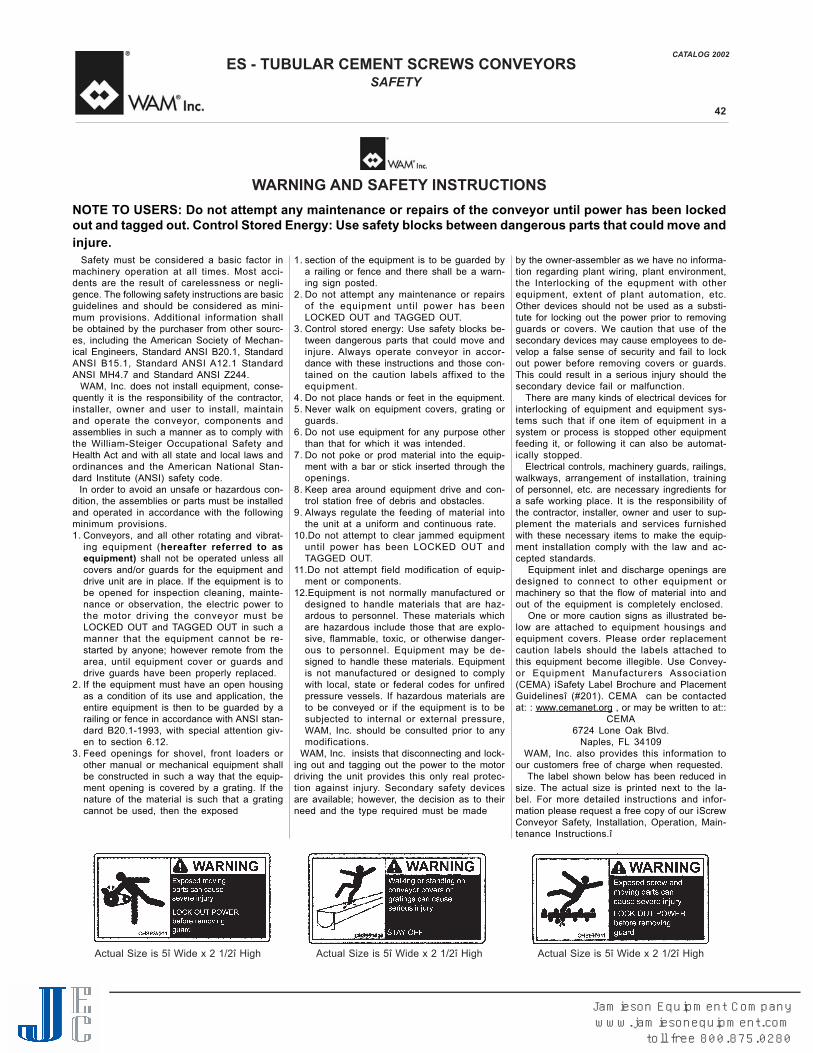
NOTE TO USERS: Do not attempt any maintenance or repairs of the conveyor until power has been lockedout and tagged out. Control Stored Energy: Use safety blocks between dangerous parts that could move andinjure.
WARNING AND SAFETY INSTRUCTIONS
Actual Size is 5î Wide x 2 1/2î High Actual Size is 5î Wide x 2 1/2î High Actual Size is 5î Wide x 2 1/2î High
Jamieson Equipment Companywww.jamiesonequipment.com
toll free 800.875.0280