Embed Size (px)
Citation preview

Keep this
manual onboard !
Installation and user's manualEN
N Installasjons og brukermanual
Mad
e in
Nor
way
© Sleipner Motor AS 2016
SLEIPNER MOTOR ASP.O. Box 519N-1612 FredrikstadNorwayTel: +47 69 30 00 60Fax: +47 69 30 00 70
w w w. s i d e - p o w e r . c o msidepower@sle ipner.no
ES 60/185 SSIDE-POWERThruster Systems

2 ES 60/185 S 1.0.3 - 2014
InnholdN
SAMSVARS ERKLÆRING Sleipner Motor AS Postboks 519 N-1612 Fredrikstad, NorgeErklærer at dette produktet med tilhørende standard kontrollsystemer er i samsvar med helse, og sikkerhetskravene i henhold til Direk-tiv 89/336/EEC FRA 23 Mai 89, korrigert av 92/31/EEC og 93/68/EEC.
Installasjons instruksjonerTekniske spesifikasjoner .............................................................3Planlegning og viktige forbehold.................................................4Tunnel installasjonPlassering av tunnel/thruster ......................................................5Utforming av tunnelåpninger ......................................................6Hvordan unngå turbulens rundt tunnelåpninger .........................7Forslag til tunnelinstallasjon på seilbåt .......................................8Tunnel installasjon i glassfiberbåter ...........................................9Thruster installasjonGearhus og motorbraket...........................................................11Oljebeholder og propeller .........................................................12Elektromotor .............................................................................13Elektrisk installasjon .................................................................14Kontrollpanel og kontrollkabler .................................................15Koblingsskjema elektrisk ..........................................................16Koblingsskjema ........................................................................17Sjekkpunktliste for kontroll av installasjon ................................18
BrukermanualViktige forbehold .......................................................................19Hvordan operere Sidepower thrustere .....................................20Vedlikehold og servise ..............................................................21Problemer og løsninger ............................................................22Garantierklæring ....................................................................23Reservedelsliste ....................................................................24Servicesentere ...................................................................... 28
Installation instructionsTechnical specifications ............................................................. 3Planning & important precautions.............................................. 4Tunnel installationPositioning of the tunnel / thruster ............................................ 5How to shape the tunnel ends ................................................... 6How to prevent drag from tunnel installation ............................. 7Possible tunnel installation in sailboats ..................................... 8Tunnel installation in a GRP boat .............................................. 9Thruster installationGearhouse and motorbracket .................................................. 11Oil tank & propeller ................................................................. 12Electromotor ............................................................................ 13Electrical installation ............................................................... 14Control panel and control-leads............................................... 15 Visual wiring diagram .............................................................. 16Technical wiring diagram ........................................................ 17Checklist for control of the installation ..................................... 18
User's manual Important user precautions ...................................................... 19How to use Sidepower thrusters.............................................. 20Maintenance & service ............................................................ 21Troubleshooting ....................................................................... 22Warranty statement .............................................................. 23Spareparts list & drawing .................................................... 24Service centres ..................................................................... 28
ContentsGB
DECLARATION OF CONFORMITYWe, Sleipner Motor AS P.O. Box 519 N-1612 Fredrikstad, Norwaydeclare that this product with accompanying standard remote control systems complies with the essential health and safety requirements according to the Directive 89/336/EEC of 23 May 1989 amended by 92/31/EEC and93/68/EEC.

3ES 60/185 S 1.0.3 - 2014
Tekniske spesifikasjonerNTechnical specificationsEN
METR
IC
IMPE
RIAL
Motor: Custom made reversible DC-motor.
Gearhouse: Seawateresistant bronze. Ball bearing at propeller shaft and combination of ball bearing and slide bearing at driveshaft. Pre-filled and sealed for life Motor bracket: Glass fibre reinforced composite material. Brass thread inserts.
Tunnel: Cross spun with rowing G.R.P tunnel
Propeller: Symetrical 3-blade design GRP reinforced composite.
Batteries: Minimum recommended battery capacity (cold crank capacity by DIN/SAE standard) ES 60/185S-12V : 350 CCA DIN/380 CCA SAE
Max. use: S2 = 3 min. or approx. 7-10% within a limited time frame.
Safety: Electronic time-lapse device protects against sudden change of drive direction. Electric thermal cut-off switch in electromotor protects against over heating (auto reset when electro motor cools down). Shearpin between electro-motor and driveshaft protects electromotor and gear system if propeller gets jammed.
If original Sidepower panel is used, the panel shuts off automatically 6 minutes after last use.
Integrated microprocessor monitors solenoids, reducing wear and risk of solenoid lock-in. Auto- stop of thruster in case of accidental solenoid lock-in or if run signal is continuous for more than 3 minutes.
Motor: Spesialutviklet reversibel DC-motor.
Girhus: Sjøvannsbestandig bronsje. Kulelagre på propellaksel. Kule og glidelager komb. på drivaksel.
Motorbraket: Glassfiberforsterket komposit materiale. Kobbertråd forsterket.
Tunnel: Kryssvevet glassfiber.
Propell: Symetrisk 3-blads propell i komposittmateriale.
Batterier: Minimum anbefalt batteri størrelse. (Kaldstart kapasitet etter DIN/SAE std.)
ES 60/185S-12V : 350 CCA DIN/380 CCA SAE
Drift tid: S2 = 3 min. Eller gjennomsnittlig 7-10% innen en beg-renset tidsperiode.
Sikkerhet: Elektronisk tidsforsinkelse forhindrer motorskade ved rask retningsendring. Motoren stanser automatisk ved overopphetning (slår seg automatisk på etter nedkjøling).
Brytepinne mellom drivaksel og motor beskytter gir hvis propell blir blokkert.
Om orginalt Side-Power panel blir brukt så vil dette slås av automatisk etter 6 minutter etter siste gang trøsteren ble brukt.
Integrerte microprossessor føler hele tiden på releet, reduserer slitasje og risk for ”heng” på relé. Trøsteren vil stoppe automatisk etter 3 minutter om det oppstår ”heng” på relé, eller om trøsteren går kontinuerlig i 3 minutter.
ES60/185S
Thrust [lbs] 132
A [in] 11,8
B1 [in] 7,3
B2max [in] 9,8
Cmax [in] 2,15
D [in] 10,6
E [in] 5,1
Fmin [in] 6,7
Motor output [Hp] 5,4
Voltage [V] 12
Weight [lbs] 48,5Note: Emin.: wall thickness of a standard Sidepower tunnel
Emax.: maximum wall thickness when using other GRP
ES60/185S
Thrust [kg] 60
A [mm] 300
B1 [mm] 185
B2max [mm] 250
C max [mm] 55
D [mm] 270
E [mm] 130
Fmin [mm] 170
Motor output [kW] 4
Voltage [V] 12
Weight [kg] 22Note: Emin.: wall thickness of a standard Sidepower tunnel
Emax.: maximum wall thickness when using other GRPsteel or aluminium tunnels

4 ES 60/185 S 1.0.3 - 2014
Viktige forholdsregler og planleggingN
Før installasjon må instruksjonsmanualen leses gjennom, og bruker må gjøre seg kjent med produktet.
Thrusteren må ikke installeres i rom som der gnister og høy varme medfører brannfare.
Elektromotoren vil produsere karbon støv fra børstene under drift slik att en lagringsplass må fysisk avskilles fra thrusteren for å unngå att det man lagrer blir støvete / møkkete.
Elektromotoren er avhengig av god kjøling, sørg derfor for ventilasjon eller god plass rundt motoren ved montering.
Elektromotoren kan monteres i alle vinkeler i fra vertikalt til horisontalt der hvor plassutnyttelsen krever det.
Hvis elektromotoren monteres i en vinkel på mer en 30o, må den støttes opp separat.
Elektromotoren må håndteres forsiktig. Den må ikke bæres etter kontaktpunktene, og motoren må ikke settes ned på drivakselen.
Følg de anbefalte målene som er oppgitt i manualen, propell eller girhus må ikke stikke ut av tunnelen.
Elektromotoren, tilhørende komponenter, kontakter eller åpne ledd i strømkabler må monteres så de ikke utsettes for vann.
Vi anbefaler å male girhuset med bunnstoff. PS sinkanoder, pakninger og propellaksel skal ikke påføres bunnstoff.
Ikke påfør gelcoat / topcoat eller lignende inne i tunellen. Det er bare plasee til ett lag primer og to lag bunnstoff mellom tunellen og propellene.
Når båten ligger på land har ikke elektromotoren den motstanden den har i vann. Motoren bruker derfor ekstremt kort tid før den oppnår ødeleggende høyt turtall. Med båten på land, unngå hurtig bytte av driftsretning da det kan forårsake skade på truster.
Denne manualen er beregnet som støttemateriell for montører med erfaring / utdanning, og har derfor ikke all informasjon nødvendig for å oppnå en korrekt installasjoner.
Installer ikke elektromotoren i nærheten av lett brennbart materiale, da motoren oppnår temperaturer over 100oC ved før den stopper automatisk.
Området intill thrusteren må ikke benyttes som lagringsplass da motoren vil bli varm samt att dette vil medføre en fare for att elektriske koblinger blir løse eller kortslutter
I de tilfeller båter skal godkjennes eller klassifiseres i henhold til internasjonal, eller spesielle standarder, er montør ansvarlig for at de gjeldende lover og regelverk følges. Sleipner Motor AS kan ikke garantere at instruksjonene i denne manualen er i henhold til alle gjeldende regelverk og standarder.
NB ! Ved feilaktig installasjon av panel, thruster eller tunnel frafaller all garanti stilt av Sleipner Motor AS.
Planning and important precautionsEN
Prior to installation, it is important that the installer reads this guide to ensure necessary acquaintance with this product.
The thruster must NOT be installed in compartments that require ignition proof electric equipment. If necessary, make a separate compartment.
The electromotor will generate some carbon dust so that any storage compartment must be separated from the thruster to prevent the stored items from becoming dusty/dirty.
If you are installing the Sidepower in a small room /compartment, it should be ventilated to ensure cooling of the electromotor.
If the height in the room you are installing the Sidepower is limited, the Sidepower can be installed horizontally or at any angle in between. - If the electro motor is positioned more than 30o off vertical, it must be supported separately. - The electromotor must be handled carefully. Do not lift it by the internal connections/main terminals or put it down on the driveshaft. - Beware to keep installation within advised measurements. No part of the propeller or gearhouse must be outside the tunnel.
The electromotor, its components, contacts / plugs or other joints in the control cables must be mounted so that they will keep dry at all times.
We advice to paint the gearhouse and propellers with antifouling. PS! Do not paint the zinc anodes, sealings or propellershafts.
Do not finish the inside of the tunnel with a layer of gelcoat / topcoat or similar. It is only room for a thin layer of primer and two layers of anti-fouling between the tunnel and the props.
With the boat on land, only run the thruster for a fraction of a second, as without resistance it will accelerate very fast to a damaging rpm. Also, while the thruster is in air, make sure that the propellers have come to a complete stop before performing a directions change of the thruster, as it might cause damage to the thruster.
This manual is intended to support educated/experienced staff and is therefore not sufficient in all details for the correct installation.
Don’t install the electromotor at close range to easily flammable objects as it will reach over 100°C before the temperature switch is activated.
Do not store items close to the thruster motor as it gets hot as well as any loose items near the thruster motor can cause problems with electrical wir-ing coming loose and short-circuiting.
When installed in boats approved or classified according to international or special national rules, the installer is responsible for following the demands in accordance with these regulations / classification rules. The instructions in this guide can not be guaranteed to comply with all different regulations/classification rules.
These instructions are only general instruction. If you are not skilled to do this work, please contact professional installers for assistance.
NB! Faulty installation of the tunnel, thruster or panel will render all warranty given by Sleipner Motor AS void.

5ES 60/185 S 1.0.3 - 2014
Plassering av tunnel og thrusterN
Velg plassering av akterthrusteren. Se skisser som viserinstallasjon og innbyggingsmål. (side 3)
Vurder følgende punkter før det lages hull i båtens akterende;
• Kontrollér at thrusterenheten ikke plasseres slik at vannstrømmen fra tunnellen hindres av hekkaggregat, trimflaps eller lign. da det vil redusere skyvekraften vesentlig.
• Thrusterenheten kan plasseres ute av senter dersom plassbehov krever det. Det er imidlertid viktig at minimumskrav til avstand opp til vannflaten overholdes. (Se skisse.)
• Kontroller at tunnellen ikke støter mot eksosutløp og at eksosen ikke suges inn i tunnellen da dette vil redusere skyvekraften vesentlig.
• Sørg for at det er mulig å montere støtte under motoren.Dette er nødvendig for å redusere belastningen på thrusterdeler og tunnel/akterspeil.
Positioning of the tunnel / thrusterEN
Determine the location for the stern thrusters; see installationdrawing and dimensional drawing. (page 3)
Before you make any cut-outs in the transom, please consider the follow-ing.
• Make sure that the water flow from the thruster is not obstructed by stern drive, trim tabs or other moving parts as this will reduce the thrust significantly.
• The propeller tunnel may be positioned off centre on the transom if required by space restrictions.
• Make sure the propeller tunnel does not interfere with the engine’s exhaust outlet pipe or allow exhaust to be sucked into the tunnel. The efficiency is reduced considerably if exhaust comes into the tunnel.
• Make sure that it is possible to install a motor support (5.1.1.). Such a device is necessary to reduce stress on the thruster components and tunnel/ transom.
Thruster model A mmES 60/185S 278

6 ES 60/185 S 1.0.3 - 2014
Montering av girhus og brakettNFitting gearhouse and motor bracketEN
Fig. 4
1. Once the position is determined, hold the propeller tunnel hori zontally on the outside of the transom and mark the cut-out for the bracket and the holes for the attachment bolts. Use the support plate (6) as a template.
2. Cut the hole for the bracket (8), in the transom, and drill the holes for the 10 mm bolts.
3. Seal the cut-out section and the bolt holes with two-component primer or equivalent sealer to prevent water from entering into the transom.
4. Buff the propeller tunnel’s interior and exterior and clean well with degreaser. Paint the tunnel with primer and antifouling paint.
5. Carefully apply suitable marine sealant on the bracket (8) and sup-port plate (6). Guide the bracket, from within, through the transom.
6. IMPORTANT: Make sure the oil nipple is positioned upwards.7. Apply sealant to support plate (6) and bolts (23/25). Place the plate
on the transom and fit the attachment bolts, from within the tran-som,through the bracket and transom. Fasten the bolts thoroughly.
8. Carefully apply sealant to the gear housing (2) before fitting the gear housing to the bracket. NB: Make sure to put sealant wherever leak-age might occur to prevent any kind of leakage. NB: Make sure the sealant does not obstruct the oil hole.
9. Guide the gear housing from within the tunnel through the hole. NB: No propeller(s) should be fitted during this process.
10. Guide the two attatchment bolts (23), from within the transom, through the bracket and fasten gear housing and propeller tunnel to the transom.
11. In some cases the tunnel flanges (1b) must be modified to fit close to the transom (11).
12. Fit the motor (12.2) to the bracket (12.3) and screw the units togeth-er. The motor has to be properly supported to support the weight of the motor and reduce tension on the transom and thrusters bracket (See 5.1.1.). NB: Place support under the motor body, do not place under the fan guard.
13. Attach the oil hose to its base on the bracket (8) and mount the oil container (31) close to the stern thruster but above the water line. The hose should be mounted in such a way that no air traps are formed which could hamper the oil flow to the gear housing.
14. Fill the oil container and open the oil drain plug in the gear housing until oil leaks out. Put the oil plug back in place. This is done to speed up the oil flow to the gear housing and also to purge any air that is left in the hose. Refill the oil container (31).
1. Når thrusterens plassering er bestemt, hold tunnellen horisontalt på utsiden av akterspeilet og merk avfor utskjæring av rørholder (8) og hull for festebolter (25). Benytt utvendig festeplate (6) som mal.
2. Skjær ut for rørholder (8) i akterspeilet og bor hull for 10 mm bolter.3. De utskjærte hullene må forsegles med to-komponent primer eller til-
svarende tetningsstoff for å forhindre vanninntrengning i akterspeilet.4. Puss/matt ned tunnellens innside og utside og rengjør med aceton.
Påfør primer og topcoat.5. Påfør egnet tetningsstoff på rørholderen (8) og festeplate (6). Før
rørholderen inn i hullet gjennom akterspeilet fra båtens inside.6. Viktig! Montér rørholderen slik at gummipluggen vender opp. Bruk tilpasset tetnigsmasse. NB! Benytt kun sjøvannsbestandig mykt tetningstoff7. Tilfør tetningstoff på festeplate (6) og bolter (23/25). Plassér feste-
platenpå akterspeilet og montér boltene fra båtens inside, gjennom rørholder og akterspeil. Trekk godt til.
8. Tilfør tetningstoff til gearhus (2) før dette monteres til rørholderen. (Se skisse)
NB: Tilfør tetningstoff alle steder vannlekkasje kan oppstå.9. Vær oppmerksom på at gearhuset er forhåndsfyllt med olje.10. Før inn girhuset gjennom hullet i tunnellen. NB: Propell(er) skal ikke være påmontert når girhuset monteres.11. Før inn de to festeboltene (23) fra innsiden, ut gjennom akterspeilet
via rørholderen og fest gearhus og tunnel til akterspeilet.12. Om nødvendig må tunnelflensene (1b) tilpasses slik at de ikke kom-
mer i konflikt med akterspeilet (11).13. Montér motoren (12.2) til overgangsflensen (12.3). Motoren må under-
støttes godt for å redusere belastningen på akterspeil og rørholder. (Se pkt. 4.2).NB: Plassér støtten under motoren som vist på skissen, ikke under ende-/viftedeksel.
14. Påfør gearhuset primer og bunnstoff. NB: Ikke påfør bunnstoff på sink anoden eller kontaktområdet melom sink og gearhus.
Påfør bunnstoff: Alle flater i tunnellen som er i kontakt med vann må påføres primer og bunnstoff.Kontrollér at thrustermontasjen ikke har noen lekkasjer når båten sjøsettes.
Apply bottom coating: All wet parts in the tunnel must be covered with bottom coating. Ensure that the in-stallation has no leaks when the boat is set afloat. NB! Do not paint the zinc anode or its contact area.
7ES 60/185 S 1.0.3 - 2014
Montering av propellN
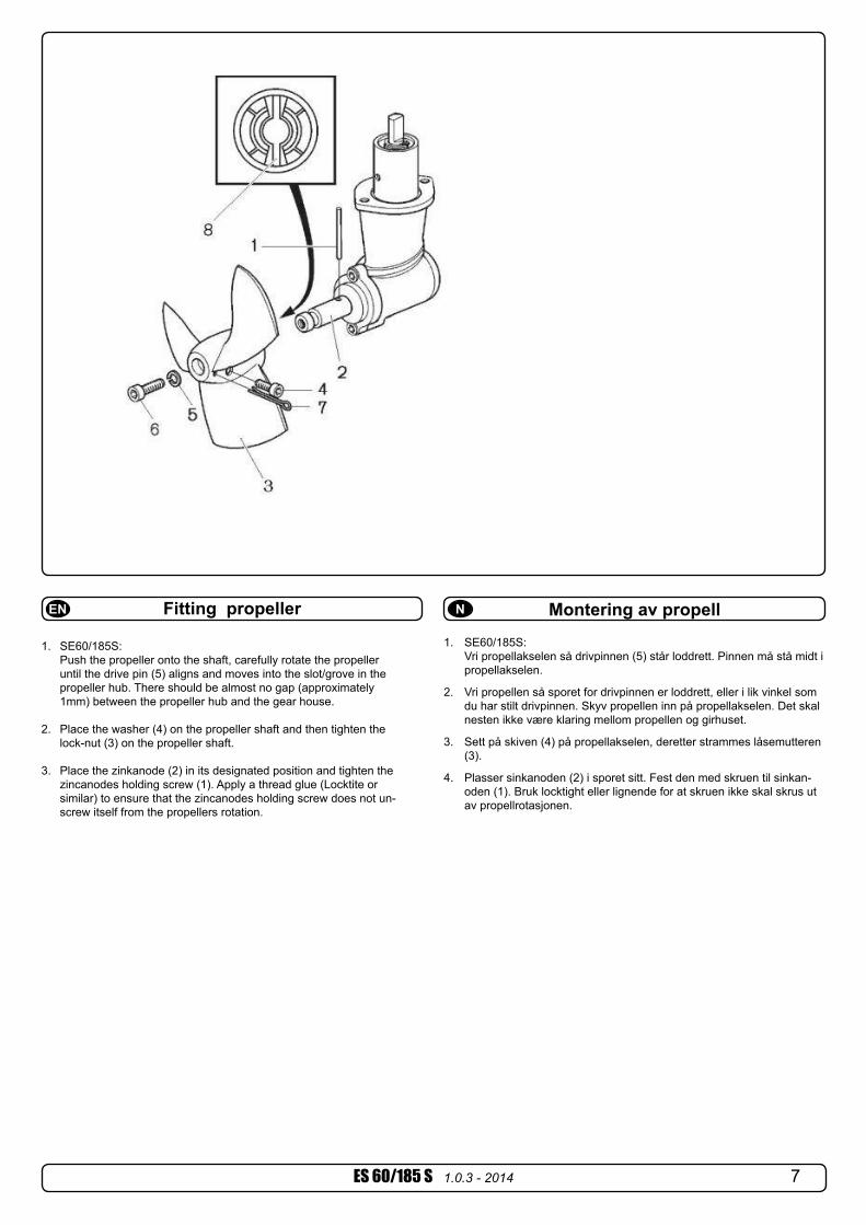
1. SE60/185S: Vri propellakselen så drivpinnen (5) står loddrett. Pinnen må stå midt i propellakselen.
2. Vri propellen så sporet for drivpinnen er loddrett, eller i lik vinkel som du har stilt drivpinnen. Skyv propellen inn på propellakselen. Det skal nesten ikke være klaring mellom propellen og girhuset.
3. Sett på skiven (4) på propellakselen, deretter strammes låsemutteren (3).
4. Plasser sinkanoden (2) i sporet sitt. Fest den med skruen til sinkan-oden (1). Bruk locktight eller lignende for at skruen ikke skal skrus ut av propellrotasjonen.
Fitting propellerEN
1. SE60/185S: Push the propeller onto the shaft, carefully rotate the propeller until the drive pin (5) aligns and moves into the slot/grove in the propeller hub. There should be almost no gap (approximately 1mm) between the propeller hub and the gear house.
2. Place the washer (4) on the propeller shaft and then tighten the lock-nut (3) on the propeller shaft.
3. Place the zinkanode (2) in its designated position and tighten the zincanodes holding screw (1). Apply a thread glue (Locktite or similar) to ensure that the zincanodes holding screw does not un- screw itself from the propellers rotation.

8 ES 60/185 S 1.0.3 - 2014
Fig. 1 Fig. 2
Montering av elektromotorNFitting the electromotorEN
Bolt tightening force (M 8):17 Nm (12,4 lb/ft)
1. Check if the springs for the brushes sit correctly on the brushes (see through the metal web around the top of the electromotor).
2. Turn the driveshaft in the gearhouse and the motor shaft so that the track for the shear pin has a corresponding direction with the shear pin in the motor shaft.
3. Slide the motor gently onto the driveshaft and motor bracket. You might have to jiggle it a bit to get it on as the fitting is tight. The electromotor can sit in all directions on the bracket. Ensure that the cable terminals are available for electric installation later.
4. Fasten the motor loosely to the bracket with the provided bolts.
5. If you are installing the motor in an angle of more than 30o off a vertical position, the electromotor needs a separate/additional support. See illustration in the measurements drawings.
6. Tighten the bolts holding the motor to the motorbracket with 17Nm /12,4 lb/ft as shown in Fig. 1.
7. Check the drive system by turning the propeller, it will be a little hard to turn (because of the gear reduction and the motor), but you should easily be able to turn it by hand. In some cases (shallow installation or workboat/fishing boat only) we recommend to protect the propeller by mounting a grid in the tunnel open-ing (Fig. 2). It is important to keep a grid to a minimum and as streamlined for the thrusters waterflow as possible, as it will decrease the effect of the thruster. Do not circular profile steel as it will decrease thrust significantly.
NB! Paint the gearhouse and propeller with antifouling made for propellers. Do not paint the propeller shaft, the zinc anodes or the end face of the gearhouse.NB! Do not run the thruster for more than very short bursts without being in the water.NB! If the boat is still being built when the electromotor is installed, it must be covered up to avoid dust from the building going into the motor and the solenoids. This cover must be removed before the thruster is being used.
1. Vri drivakselen i girhuset og akslelen i elektromotoren så sporet for brytepinnen i drivakselen korresponderer med brytepinnen i motor akselen.
2. Sett motoren forsiktig ned på motorbraketten og drivakselen. P.g.a. nøyaktig tilpasning kan det være vanskelig å treffe sporet for bry-tepinnen med brytepinnen. Elektromotoren kan stå i alle retninger på brakketen.
3. Fest motoren løst til braketten med bolter.4. Hvis motoren er vinklet med mer en 30o trenger motoren separat
oppstøtting.5. Stram boltene med 17Nm/12,4 lb/ft som vist i fig. 1.6. Sjekk systemet ved å vri på propellen. P.g.a. utvekslingen i gir-huset
vil dette være tungt, men det skal være mulig å vri den for hånd.7. Sjekk at børstefjærene sitter korrekt på børstene (gjøres ved å se
gjennom gitteret på siten av motoren).I visse tilfeller (ved grunne installasjoner, fiske/arbeidsfartøy fartøy) anbefaler vi å beskytte propell og girhus ved å montere et gitter foran tunnelåpningene (Fig. 2). Det er da meget viktig å beholde strømlinjefor-men, og å begrense gitteret til et minimum. Feil installasjon kan begrense skyvekraften med 10%.NB ! Påfør bunnstoff på girhus og propell for å unngå vekst som kan svekke thrusterens effekt. Sinkanoder propellaksling og tetninger skal ikke stoffes.NB ! Thrusteren må kun kjøres i meget korte perioder når den ligger på land.NB ! Hvis båten fortsatt er under bygging når thrusteren blir montert må motoren dekkes til for å unngå at støv og lignende trenger inn i girhus og elektromotor. Dekket må fjernes før motoren tas i bruk.

9ES 60/185 S 1.0.3 - 2014
Elektrisk installasjonN
• Forklaring til elektrisk tabell - Kabellengder tilsvarer + kabelen, og - kabelen (Frem og tilbake). - Min. batterikap. som kaldstartkapasitet (CCA), ikke Ampere. - Bruk trege sikringer for å forebygge spenningsfall.• Det er viktig å bruke kabler som er store nok, og et batteri med god ka-
ldstartkapasitet for å drive thrusteren. Det er Volten som kommer frem til motoren under kjøring som bestemmer turtallet til motoren og dermed også skyvekraften. Vær vennlig og jamfør listen over for minimum anbefalte kabel, og batteristørrelse.
• En hovedstrømbryter (*C) som ikke medfører stor spenningsfall må installeres på thrusterens plusskabel. Det bør være mulig å skru av strømmen til thruster uavhengig av resten av det elektriske systemet, når man ikke er om bord, eller i et nødstilfelle. Bryteren bør plasseres på et tilgjengelig sted, og båtens instruksmanual må ta for seg at denne skal skrus av slik som de andre hovedbrytere.
• Det må installeres sikring på pluss strømkabelen for å beskytte mot kortslutning av hovedstrømkablene. Sikringen bør være av høy kvalitet, noe som vanligvis betyr at de er fysisk store, for å unngå spenningsfall som ofte er resultatet av å bruke mindre, enklere sikringer. Sikringen skal være en treg type som tåler amper trekket til elektromotoren i minimum 5 min.
• En kretsbryter kan erstatte sikringen og hovedstrømbryteren hvis den har de samme funksjonene.
• Kabelendene kan må påmonteres terminaler og disse må isoleres mot alt som ikke er riktig kontaktpunkt.
• Det er viktig att kabelsko trekkes korrekt fast på koblingsbolt. Kontra mutter på koblingsbolt må holdes fast ved tiltrekking (Fig. 2). Minus kabelen (*A) tilkobles A1 (-) terminalen. Pluss kabelen (*B) tilkobles "+" terminalen.
SE30/125S-SE40/125S: ø8mm / 5/16" bolt, dra til med 15 Nm. SE 60/185 S: ø10mm / 3/8’’ bolt, dra til med 15 Nm.
Electrical installationEN
Battery12V or 24V
+
-
M
-
+
*D*C
Fig. 1 Fig. 2
• Explanation of electrical table - All cable lengths are the total of + and - (to and from). - Battery size is stated as minimum cold crank capacity, not Ah. - Use slow fuse rated to hold stated Amp-Draw for min. 5 minutes. * Cable size and main battery size when an extra bow battery with minimum the CCA mentioned as A is installed.• It is important that you use a good cable size and batteries with a high cranking capacity to feed the thruster, because it is the actual voltage at the motor while running the thruster that decides the output rpm of the motor and thereby the actual thrust. Please see the list below for advised min. sizes of cables and batteries. You can of course use larger cables for even better results.• A main switch (*C) that can take the load without noticeable voltage drop must be installed in the main positive lead so the power for the thruster can be turned off independent of the rest when not on board or in emergencies. This should be placed in an easy accessible place and the boats instructions should inform that this should be turned off like the boat’s other main switches.• We also advice to install a fuse (*D) in the positive lead for protection against short circuiting of the main cables. This fuse should be of a adequate quality which normally means that it is physically large as these have less voltage drop than the simple / small ones. It should be of the slow type and sized to take the amperage draw for at least 5 minutes.• A circuit breaker can be used instead of the fuse and main power switch as long as the functionality is the same. • The cable ends must be fitted with terminals and these must be well isolated against contact with anything but the proper connection point.• Terminals must be properly tightened. Secure/hold inner nut when tightening (Fig. 2). Tighten with max: 15 Nm/11lb/ft.The negative/ minus cable (*A) connects to the A1 (-) terminal. The positive/plus cable (*B) connects to the “+” terminal. SE30/125S-SE40/125S: ø8mm / 5/16" bolt. Tighten with 15 Nm / 11 lb/ft. SE 60/185S: ø10mm / 3/8" bolt. Tighten with 15 Nm/11lb/ft.
NB! Very important to check the following with mainswitch in off position: After all electrical connections have been completed check with an ohm meter that there is no electrical connection between electro- motor body and positive terminal on the motor and between the electromotor body and the negative (A1) terminal on the motor. If you feel unsure on how to perform this check, contact skilled personnel for guidance.
Battery & cable recommendations:
Minimum and recommended cable dimensions can be identical due to safety margins and cable heat considerations for short cable lenghts.* Minimum or recommended cable cross section in mm2
ES60/185S 12 V 340 A DIN: 350 SAE:665
mm2
AWG35 1
50 1/0
60 2/0
95 3/0
95 3/0
2x 70 2x 2/0
120 4/0
2x95 2x 3/0
2x 95 2x 3/0
2x120 2x 4/0
2x1202x 4/0
280*
24 V 170 A DIN: 175 SAE: 332
mm2
AWG25 1
35 1
25 1
35 1
25 1
35 1
35 1
50 1/0
50 1/0
60 2/0
60 2/0
702/0
Model Volt-age
Nom-inal current draw
Min. battery CCA
>7m total + & -
7-14m total + & -
15-21m total + & -
22-28m total + & -
28-35m total + & -
36-45m total + & -
Min. Rec. Min. Rec. Min. Rec. Min. Rec. Min. Rec. Min. Rec.
Fuse/Sikring (*D)Model Fuse Part no.ES60/185S 12V 250A ANL250*

10 ES 60/185 S 1.0.3 - 2014
Kontrollpanel og kontrollkablerKontrollpanel installasjon:• Alle standard ”Sidepower” panel for 1999 modeller og senere kan
brukes i enhver kombinasjon med hverandre.• Alle fireleders, toveis kontrollbrytere kan også brukes hvis de er utstyrt
med en ”av og på” bryter for som bryter strømmen til bryteren.• Det er mulig å installere så mange kontrollpanel som ønskelig ved å
bruke ”Sidepower” Y-stykker.• Hvis thrusteren skulle motta flere forskjellige signaler samtidig så kutter
den til den mottar kun et signal fra et kontrollpanel.• Ved bruk av Sidepower originalutstyr er alle elektriske kontakter klare til
å plugges i sammen.• Hvis kjøreretningen ikke stemmer overens med forventningene må blå
og grå ledning på Thruster-releet byttes om. For å få til dette må den elektroniske kontrollboksen snus 180o i braketten.
• Alle paneler må ha et fjær oppheng som gjør at de automatisk hopper til nøytral posisjon etter bruk.
• Monteringsveiledning for panelet følger panelet.• Thrusterpanelet bør monteres et sted det er lett å bruke. Siden gass og
gir ofte brukes samtidigt som thrusteren, er det ofte en god løsning å ha muligheten å operere disse med hver sin hånd.
Pinne konfigurasjon for fireleder AMP kontakt:Pinne 1: Svart = JordPinne 2: Blå = Aktiverer thruster rele StyrbordPinne 3: Grå = Aktiverer thruster rele BabordPinne 4: Rød = Pluss til kontrolpanel
NControl panel and control-leadsEN
1 2
3 4
2 1
34
Pin 4Pin 3Pin 2Pin 4Pin 3Pin 2
M12 or 24V SLEIPNER
SI D EPO W ERTHRUSTER
OFFON ON
SLEIPNER
SI D EPO W ERTHRUSTER
OFFON ON
Control panel installation:• All standard Sidepower control panels of 1999 models and later can be used in any combination as well as any two way switching device when installed with an ON/OFF switch that breaks control power to this switch.• You can install as many panels as you wish by using optional Y-connectors. If two or more panels are operated at the same time in opposite directions, the electronic control box will stop the thruster until it only receives a signal to go in one direction.• When using original Sidepower equipment it is all “plug & go”.• If the drive direction of the thruster is the opposite of what expected, the blue and grey wire must be changed on the thruster solenoid. You must turn the electronic control box 180o around in its clip to do this.• All controls must have spring load for automatic return to neutral position.• The mechanical installation of the panel is described in the manual following the panel.• The thruster control should be placed in a position were it is easy to use, and it is very common to use the thruster at the same time as your gear/throttle lever so it is normally a user friendly solution to be able to access these with one hand for each control.
Pin configuration of 4 pole AMP contact:Pin1: BLACK = GroundPin2: BLUE = Engages thruster SB solenoidPin3: GREY = Engages thruster Port solenoidPin4: RED = Positive voltage for control panel
32 SP 75 Ti / SP 95 Ti / SP 125 Ti 2.5.1- 2007
Schaltplan - Übersicht
"Visual" wiring diagramGB
D Schema di connessione visivoI
Schéma visuel de branchementF
Visualinen kytkentäkaavaFIKoblingsskjema elektriskN
A2
A1
Fuse
96
81
24
5
red
grey
blue
blac
k
grey
blue
brow
n
red
6 12
32i
Ele
ctro
nic
cont
rol b
ox
Ther
mal
switc
h
Bat
tery
12V
or 24V
Bat
tery
mai
nsw
itch
M
4 3 2 1
3
red
red
blac
k
7
whi
te
NB! Make sure to not useany electronic interfacebox (delay box) older thanthe 6 1232i (ex. 6 122x)on SP75Ti, SP95Ti, andSP125Ti.

11ES 60/185 S 1.0.3 - 201432 SP 75 Ti / SP 95 Ti / SP 125 Ti 2.5.1- 2007
Schaltplan - Übersicht
"Visual" wiring diagramGB
D Schema di connessione visivoI
Schéma visuel de branchementF
Visualinen kytkentäkaavaFIKoblingsskjema elektriskN
A2
A1
Fuse
96
81
24
5
red
grey
blue
blac
k
grey
blue
brow
n
red
6 12
32i
Ele
ctro
nic
cont
rol b
ox
Ther
mal
switc
h
Bat
tery
12V
or 24V
Bat
tery
mai
nsw
itch
M
4 3 2 1
3
red
red
blac
k
7
whi
te
NB! Make sure to not useany electronic interfacebox (delay box) older thanthe 6 1232i (ex. 6 122x)on SP75Ti, SP95Ti, andSP125Ti.
"Visual" wiring diagramEN N Koblingsskjema elektrisk
NB! Make sure to not use any electronic inter-face box (delay box) older than the 6 1232i (ex. 6 122x)

12 ES 60/185 S 1.0.3 - 2014 33SP 75 Ti / SP 95 Ti / SP 125 Ti 2.5.1 - 2007
SchaltplanD
Technical wiring diagramGB
Schema di connessione tecnicoI
Schéma technique de branchementF
Tekninen kytkentäkaavaFIKoblingsskjemaN
M
Ther
mal
switc
h
Elec
tron
icin
terf
ace
box
6 12
32i
A2
A1
4 pi
nA
MP
conn
ecto
r
On
Mot
or
4 2 1 3
Fuse
Bat
tery
mai
nsw
itch
1 54
2 689re
d (+
)
grey
(sig
+)
blue
(sig
+)
blac
k (-)
red
grey
(sig
-)
blue
(sig
-)
brow
n
3re
d
Fuse
din
side
1A
blac
k
7w
hite
NB! Make sure to not useany electronic interfacebox (delay box) older thanthe 6 1232i (ex. 6 122x)on SP75Ti, SP95Ti, andSP125Ti.
Technical wiring diagramEN N Koblingsskjema
NB! Make sure to not use any electronic interface box (delay box) older than the 6 1232i (ex. 6 122x)

13ES 60/185 S 1.0.3 - 2014 33SP 75 Ti / SP 95 Ti / SP 125 Ti 2.5.1 - 2007
SchaltplanD
Technical wiring diagramGB
Schema di connessione tecnicoI
Schéma technique de branchementF
Tekninen kytkentäkaavaFIKoblingsskjemaN
M
Ther
mal
switc
h
Elec
tron
icin
terf
ace
box
6 12
32i
A2
A1
4 pi
nA
MP
conn
ecto
r
On
Mot
or
4 2 1 3
Fuse
Bat
tery
mai
nsw
itch
1 54
2 689re
d (+
)
grey
(sig
+)
blue
(sig
+)
blac
k (-)
red
grey
(sig
-)
blue
(sig
-)
brow
n
3re
d
Fuse
din
side
1A
blac
k
7w
hite
NB! Make sure to not useany electronic interfacebox (delay box) older thanthe 6 1232i (ex. 6 122x)on SP75Ti, SP95Ti, andSP125Ti.
Signatur: ............................................... Dato: ................................
Anbefalt før leverings test for installør / verft som ikke bruker andre kvalitetskontroll systemer!
Thrustertype: ................................................ Volt: .............................
Serienummer: .....................................................................................
Leveringsdato: ....................................................................................
Korrekt kjørerettning per kontrollpanel: ..............................................
Spenning målt på thruster under kjøring: ...........................................
Strømkabler: .......................................................................................Skottet hvor thrusteren er montert er isolert fra kjølvann og har ingen åpenbar risiko for lekkasje.
Kommentar fra installør:
Propeller is fastened correctly to the shaft. Propeller turns freely in tunnel. The zinc-anode holding screw is tightened well with thread glue. Anti-fouling have been applied to the gearhouse and propeller but
NOT on the zincanode or the gearhouse lid where the propeller is fastened.
The brush springs are fitted correctly on the brushes in the electromo-tor (check through the grid around the top end of the motor).
Correct drive direction as per controlpanel. All electrical connections are clean, dry and tight, and the correct
cable, fuse and main switch sizes have been used. With a ohm meter check that there is no electrical connection
between electromotor body and positive terminal on the motor and between the electromotor body and the negative (A1) terminal on the motor.
The bolts holding the gearhouse and motorbracket together are tight-ened correctly.
The bolts holding the electromotor to its bracket are tightened cor-rectly.
ChecklistEN
The thruster has been installed as per the instructions in this manual and all points in checklist above have been controlled.
Signed: ................................................ Date:...............................
Extra pre-delivery tests by installer/yard who does not use other quality control systems !
Thruster type: .................................................. Voltage: ....................
Serial number: ................................. Date of delivery: .......................
Correct drive direction as per control panel: .....................................
Voltage at thruster when running: ......................................................
Battery cable size used: .....................................................................
The compartment where the thruster is fitted is isolated from general bilge water and has no obvious or suspected risks for flooding.
Other comments by installer:
SjekklisteN
Propellen er festet til akselen på korrekt vis. Propellen roterer fritt i tunnel. Festeskruen til sinkanoden er festet med gjengelim. Bunnstoff er påført girhus og propell, men ikke på sinkanode, tetnin-
ger eller propelaksel. Børstefjærene er riktig plassert mot børstene. Dette sjekkes ved å se
gjennom gitteret på siden av motoren. Kontrollpanel gir korrekt kjøreretning på thrusteren. Alle elektriske koblinger er rene, tørre og tette. Korrekte kabler,
sikringer og hovedstrømsbryter er brukt. Boltene som festet braket til girhus er festet korrekt. Boltene som festet motor til braket er festet korrekt.
Thrusteren er installert i henhold til instuksene gitt i denne manualen, og alle punkter i sjekklisten er kontrollert.
14 ES 60/185 S 1.0.3 - 2014
Important user precautionsEN
• Forviss deg om at du kjenner plasseringen av hovedstrømsbryteren til baugthrusteren, som kutter all strøm til thrusteren, så thrusteren kan skrus av i nødstilfelle.
• Før berøring av noen del av thrusteren må alltid strømmen skrus av. En tilfeldig start kan volde stor fysisk skade.
• Skru alltid av kontrollpanelet etter bruk.• Den maksimale sammenhengende kjøretiden for en elektrisk
thruster er ca. 3 min. da vil en føler automatisk skru av motoren når den når en viss varme. Dette må tas i betraktning når en manøver planlegges.
• Dette betyr at ved manøvere som tar lang tid vil ikke thrusteren kunne brukes hele kontinuerlig. Ved manøvere som tar lang tid kan man bruke thrusteren i ca 10 % av tiden, avhengig av tempraturen i vannet.
• Bruk aldri thrusteren når noen er i vannet, thrusteren vil trekke gjen-stander til seg og kontakt med propellen vil volde alvorlig skade.
• Kjør aldri thrusteren i mer enn 1 sek. når båten er på land. Uten motstand fra vannet vil thrusteren nå ødelegende turtall svært fort.
• Hvis thrusterne stopper å gi skyvekraft mens motoren er i gang, er det trolig oppstått problemer i girsystemet. Stopp umiddelbart å kjøre motoren, og skru den av. Uten motstand fra vannet vil thrusteren nå ødelegende turtall svært fort.
• Når man forlater båten skal alltid hovedstrømsbryteren slås av.• Vi anbefaler å ha motoren i gang når thrusteren kjøres. Da vil bat-
terien vedlikeholdes, og det vil være høyere spenning til elektromo-toren. Høyere spenning gir høyere turtall og bedre ytelse.
• Ytelsen til en baugthruster avhenger av hvilken spenning motoren mottar under kjøring. Kapasiteten til batterier avtar etter hvert som de blir eldre, og dermed også ytelsen til thrusteren. Ved å installere nye batterier vil thrusteren yte maksimalt igjen.
• Kun en kontroll skal brukes av gangen, hvis to kontroller brukes mot-satt vei vil thrusteren stoppe automatisk. Hvis to paneler opereres samme vei vil ikke dette skje.
• Hvis thrusteren ikke fungerer tilfredsstillende må feilen lokaliseres og rettes så snart som mulig, for at ikke thrusteren skal ta ytterligere skade, skru av hovestrømsbryteren hvis feilen er av elektrisk art.
Viktige brukerforebeholdN
• Ensure that you know the location of the main battery switch that disconnects the thruster from all power sources (batteries) so that the thruster can be turned off in case of a malfunction.• Always turn the main power switch off before touching any part of the thruster, as an incidental start while touching moving parts can cause serious injuries.• Always turn the control device off when the thruster is not in use.• The maximum continues usage time of the electrical thruster is approximately 3 minutes. The electromotor has a built in thermal cut-off switch that will shut off the electromotor if it is overheating and re-engage it when it has cooled down some. This should be considered when planning your maneuvering.• This also means that the thruster will limit its total running time per time period so that you can not count on the thruster to hold you in a current and side wind for extensive time periods. Depending on the surrounding temperatures etc. the thruster will be able to run approximately 10 % of the time.• Never use a thruster close to somebody in the water, as the thruster will draw objects close by into the tunnel and contact with the rotating propellers will cause serious injuries.• With the boat on land, only run the thruster for a fraction of a second, as without resistance it will accelerate very fast to a damaging rpm. Also, while the thruster is in air, make sure that the propellers have come to a complete stop before performing a directions change of the thruster, as it might cause damage to the thruster.• If the thruster stops giving thrust while the electromotor is running, chances are that there is a problem in the drive-system. You must then immediately stop trying to run it, and turn it off, as running the electromotor for more than a few seconds without resistance from the propeller, can cause serious damage to the electromotor.• When leaving the boat always turn off the main power switch for the thruster.• We advice to always keep the main engine(s) running while using a thruster. This will keep the batteries in a good charge condition. This will also give better performance to the thruster, as a higher voltage at the thruster results in a higher torque (power) in the electromotor.• Please note that the performance of a thruster strongly depends on the voltage available at the electromotor. This voltage will decrease by time because aging batteries have a reduction of capacity. By installing new batteries the effect of the thruster should be back at the original level.• Make sure that only one control is used at the same time, if two panels are operated in opposite directions at the same time the thruster will not run at all. If they are operated in the same direction the thruster will run in this direction.• If the thruster is not performing or functioning as usual, the cause for this must be found and corrected as soon as possible so to avoid causing any other or further damage to the equipment. You must also turn off the main battery switch immediately in case the problem is of electric origin.• Never store anything (e.g. equipment, sails, ropes etc.) in the same compartment as the thruster. When the thruster runs for a longer period it will get hot and will cause damage.

15ES 60/185 S 1.0.3 - 2014
Hvordan bruke Sidepower thrusterN
Hvordan bruke en baugthruster1. Skru på hovedstrømmen (skru alltid av hovedstrømmen når du ikke er
om bord i båten).2. Det er fordel om de prøver baugthrusteren på åpent vann den første
gangen.3. Skru på kontrollpanelet ved å trykke inn begge ”on” knappene på
Sidepower panelet. Hvis annet en originalt panel brukes må dette skrus på.
4. Snu baugen i ønsket retning ved å trykke rød knapp for babord, og grønn knapp for styrbord. Hvis du har joystickpanel så må stikka dyttes i den retning baugen skal vendes. Andre kontrollenheter som fotbrytere, eller brytere på gass hendel kan også brukes. Disse er vanligvis logisk installert og lette og operere. Ved tvil lønner det seg og prøve på åpent vann først.
5. Avhengig av hvor stor fart baugen får sideveis må thrusteren stoppes før baugen er i riktig posisjon, dette fordi baugen vil fortsette sideveis litt etter thrusteren skruses av.
Hvordan bruke en enkel hekkthruster Enkelte båter vil av plassmessige, eller andre hensyn bare instal-
lere en hekkthruster. I disse tilfeller brukes hekkthrusteren på samme måte som baugthrusteren.
Hvordan bruke hekk og baugthruster kombinert Kombinasjonen av baug og hekkthruster gir en total kontroll
over båtens bevegelser p.g.a. muligheten til å bevege hakken og baugen uavhengig av hverandre. Båten kan skyves sidelengs og dreies rundt sin egen akse.
• Det er også her fordel å prøve ut systemet på åpent vann.
How to use Sidepower thrustersEN
How to use a bowthruster1. Turn main power switch for the bowthruster on. (Always turn off the main power switch when not onboard.)2. Please take some time to exercise thruster usage in open water to avoid damages to your boat.3. Turn the control panel on by pushing both “ON” buttons on the original Sidepower panel simultaneously. If another type of control is installed, engage the On/Off switch for the bowthruster.4. Turn the bow in the desired direction by pushing the red button for port movement or the green button for starboard movement. If you have a joystick control, move it in the direction you wish the bow to move. Other controls like footswitches or toggle-switches on the throttle can be used. These are normally logically installed, so by engaging the port control, the bow goes port etc. In case of any doubts, try in open waters first.5. Depending on the sideways speed of the bow, you must disengage the control device shortly before the bow is in the desired direction, as the boat will continue to move after stopping the bowthruster. How to use a single stern thruster Some boats might however have installed a single stern thruster because of space limitation in the bow. In this case the stern thruster is used in the same way as a single bow thruster (see above) for moving the boat’s stern.How to use a bow and stern thruster combined The combination of a bow and stern thruster offers total manoeuvrability to the boat and the opportunity to move the bow and the stern separately from each other. This enables you to move the boat sideways in both directions and to turn the boat around its own axis staying at the same place. • Again, if in doubt, try in open water first!
38 SP 30 S2i / SP 40 S2 i/ SP 55 Si 3.5 - 2005
Benutzung einer Bugschraube1. Die Bugschraube über deren Hauptschalter einschalten. Den
Hauptschalter immer ausschalten, wenn niemand an Bord ist.2. Nehmen Sie sich etwas Zeit, um sich auf offenem Gewässer
mit der Steuerung der Bugschraube vertraut zu machen.3. Original Sidepower Panels durch gleichzeitiges Drücken der
"ON" Knöpfe einschalten. Falls eine anderes Panel verwendetwird, den On/Off Schalter für die Bugschraube einschalten.
4. Den Bug in die gewünschte Richtung bewegen; rot / BackbordKnopf für Richtung Backbord, grün / Steuerbord Knopf fürRichtung Steuerbord. Bei Verwendung eines Joystick Panels,dieses in die gewünschte Richtung bewegen. Kontrollpanelswie Fuß- und Kippschalter können ebenfalls verwendet werden.Diese sind normalerweise logisch installiert, d.h. der Bug folgtder entsprechenden Panelvorgabe. Bei Unklarheit, zunächstauf offenem Gewässer ausprobieren.
5. Abhängig von der Geschwindigkeit, mit der sich der Bug seit-wärts bewegt, muß die Steuerung bereits vor Erreichen desEndpunktes aufhören, da sich der Bug noch etwas in dieentsprechende Richtung "nachbewegt".
Benutzung einer HeckschraubeEinige Schiffe haben aufgrund von Platzmangel im Bug statt-dessen eine Heckschraube installiert. In diesem Fall ist dieHeckschraube wie eine Bugschraube (siehe oben) zu verwen-den, um das Heck zu bewegen.
Gemeinsame Benutzung von Bug- und HeckschraubeDie Kombination von Bug- und Heckschraube bietet die unab-hängige Manövrierbarkeit von Bug und Heck. Dies eröffnet dieMöglichkeit, das Boot seitwärts in beiden Richtungen oder aufder Stelle um die eigene Achse zu bewegen.
• Bei Unklarheit, zunächst auf offenem Gewässer ausprobieren.
Benutzung von Sidepower ThrusternD
How to use a bowthruster1. Turn main power switch for the bowthruster on. (Always turn off the
main power switch when not onboard.)2. Please take some time to exercise thruster usage in open water to
avoid damages to your boat.3. Turn the control panel on by pushing both “ON” buttons on the
original Sidepower panel simultaneously. If another type of controlis installed, engage the On/Off switch for the bowthruster.
4. Turn the bow in the desired direction by pushing the red button forport movement or the green button for starboard movement. If youhave a joystick control, move it in the direction you wish the bow tomove. Other controls like footswitches or toggle-switches on thethrottle can be used. These are normally logically installed, so byengaging the port control, the bow goes port etc. In case of anydoubts, try in open waters first.
5. Depending on the sideways speed of the bow, you must disengagethe control device shortly before the bow is in the desired direction,as the boat will continue to move after stopping the bowthruster.
How to use a single stern thruster Some boats might however have installed a single stern thruster
because of space limitation in the bow. In this case the stern thrusteris used in the same way as a single bow thruster (see above) formoving the boat’s stern.
How to use a bow and stern thruster combined The combination of a bow and stern thruster offers total
manoeuvrability to the boat and the opportunity to move the bowand the stern separately from each other. This enables you to movethe boat sideways in both directions and to turn the boat around itsown axis staying at the same place.
• Again, if in doubt, try in open water first!
Turn boat to port
Turn boat to starboardTo turn panel OFF
To turn panel ONBow+Stern
Thruster
How to use Sidepower thrustersGB

16 ES 60/185 S 1.0.3 - 2014
VedlikeholdN
» Etterstram boltene som holder girhuset sammen med braketten ved første på-land servicen med oppgitt moment (s. 13).
» Hold propellen og girhuset fritt for algevekst ved å påføre bunn-stoff før hver sesong. PS ! Sinkanoder, tetninger og propellaksel skal ikke påføres bunnstoff, pass på så det ikke kommer bunnstoff i gjenge-sporene til propellmutteren.
» Skift sinkanode før hver sesong, eller når ca. halvparten av sink-anoden har tæret bort. Bruk Locktite eller lignende på skruen til sinkanoden for at den ikke skal falle av. Ta i betraktning at under noen vannforhold er det nødvendig å montere en ekstra sink-anode for å være sikker på at de skal vare i hele perioden mellom vedlikehold. Ta kontakt med din forhandler for informasjon om hvordan å gjøre dette.
» Som en del av det periodiske vedlikeholdet av din båt, og før hver sesong må følgende ting sjekkes:
• Propellen sitter godt festet.
• Boltene som holder elektromotoren til braketten sitter.
• Skottet der baugpropellen er montert skal være rent, og tørt. Hvis det er vann i skottet må lekkasjen finnes og tettes.
• Alle elektriske tilkoblingspunkter er rene, og godt festet.
• Pass på at Deres batterier er i god stand så det kan gi høy spenning til thrusteren. Redusert spenning vil gi redusert effekt på thrusteren.
MaintenanceEN
ElectromotorDirectional solenoidsMotorbracket for holding motor and gearhouse together on the tunnel.Breakpin secures the electromotor if propeller is jammed. Changeable from inside the boat.
4
1
3
2
» Retighten the bolts holding the gearhouse to the motor bracket during the first on-land service with the specified bolt tightening force (see page 13).» Keep the propeller and gearhouse clean from growth by painting with antifouling before every season. PS! The zinc anode, sealing and propeller shafts must absolutely not be painted. Be careful that you don’t fill paint in the “tracks” in the gearhouse that the propeller hub moves in.
» Change the zinc anode before every season, or when about half the anode is gone. Always use a sealant on the screw holding the zincanode to ensure that it does not fall off. Please observe that in some waterconditions it can be necessary to install an extra zincanode to ensure that it lasts for the whole period between regular service lifts of the boat. Consult your dealer for information on how to do this.
» As a part of the seasonal service of your boat, and before every season, always check that:
• The propeller is securely fastened
• The bolts holding the electric motor to the motor bracket are fastened correctly.
• The area where the thruster is installed is clean and dry. If there are signs of water you must try to find the source and eliminate it.
• All electrical connections are clean and fastened firmly.
• Make sure that your batteries are in a good condition so that the thruster gets a good voltage. Old or bad batteries will give a reduced performance from the thruster.
1
2
3
4

17ES 60/185 S 1.0.3 - 2014
Before seeking assistance at the help desk of your Sidepower dealer/distributor please perform these tests and make notes of all measurements to ensure that they have as much information as possible to work on.NB! All check points and solutions must be carried out after consulting the relevant information elsewhere in this manual to under-stand how the system is intended to work. If you are unable to understand what to check, you must consult a professional.
Trouble shootingEN
Solution
Check the flexible coupling/shear pin and the motor installation to ensure correct con-nection of the flexible coupling before re-fitting the electromotor.
Re-fasten or replace the propeller and/or key/drive pin.
In case of a failure inside the gearhouse, we advice to get a replacement gear-house instead of attempting to repear the internal gear and bearing system.
If wrong, contact your dealer or distributor to obtain parts with the correct voltage.
The no load voltage should be: 12V system =12,7V / 24V system = 25,4 V. If below 12,3V / 24,6V your batteries are not in a good charge state or worn out and must be recharged or replaced before trying to run the thruster.
If less than 8,5V at the thruster the voltage is to low for the thruster to operate correctly. In a 24V boat the thruster will operate down to approx. 12V, but the performance will be very bad. Find and correct the reason for this low voltage which will probably be one or more of these points: main battery cable sizes and connections, battery size and condition, fuse and main power switch performance.
If the thruster runs in both directions, try the same in the connector that goes into the back of the control panel. If it also works in this position, check the contact and wires on the back of the panel and try to engage this again by pushing both ON buttons simultaneously. If the panel does not turn on (see control light), measure the voltage between the Red and the Black in the contact going into the thruster. If the voltage is good, chances are that the panel is not working.If it works by the thruster, and not by the panel there is a bad contact or a broken lead the control cables between these two test points.Measure that you have the correct voltage between the Red (+) and all the other col-ours in the contact. If you do not get a reading.
Between main minus (A1 on motor) and the blue and the grey wire connected to the sides of the main solenoids you should have the same voltage as betweenthe main battery cables on the thruster. If not, check that the internal wiring on the so-lenoid is ok and measure that there is contact through the magnetising spools of each side of the solenoid (measure between the red and blue on one side, and red and grey on the other side with an Ohm meter.). If there is no contact between these, the solenoid is broken and needs replacing.
If less than 10,5 V / 21V the thruster will not perform at specified effect.
If one or more brushes are loose/has no tension from the brush-spring, the perfor-mance will be low.
If there is growth in the tunnel, this will disturb/block the waterflow and especially bar-nacles on the propeller will greatly reduce performance.
Re-charge battery(ies), if this is not sufficient, replace battery(ies).Check for bad cable connections, if necessary tighten/re-adjust connections.Check cable size in accordance to manual.
Shut off thruster main switch, tap slightly on the solenoid to see if it will release. Turn on thruster main switch. If solenoid is still in lock-in mode, replace solenoid.
Check
If the flexible coupling between the motor and driveshaft is not fitted correct inside the boat. Are the propellers in the tunnel fastened correctly on the prop-shaft (key/drive pin present)
With the motor removed, turn the driveshaft from inside the boat to feel if the gears are engaging and turning the prop-shaft.
Check that the voltage of the electromotor is correct for your installation by their labels.
Check the voltage at the thruster between main minus input (A1 on motor) and main plus input point:
Check the voltage at the thruster while you are trying to run it. Keep main engine(s) running to have continous charge to the batteries.
If the main solenoids on the thruster are not even trying to engage (clicking) they are probably not getting a "run" sig-nal from the control system. Try to run the thruster without the panel by directly connecting the red and the blue or the red and the grey wires in the controlcable contact coming from the thruster.
If the thruster does not run at all, or only in one direction in the above tests, check the internal wiring on the thruster motor, solenoids and electronic motor inter-face box to be in accordance with the wiring diagram and ensure that all connections are clean and tight.
Check voltage at thruster when running.
Check that all the brush-springs sits correctly on the brus-hes in the electromotor.
Check that the propeller, gearhouse and tunnel is free from growth/barnacles etc.
Solenoid flapping, most probable cause: low voltage.
Solenoid lock-in, auto stop of thruster, auto retry every 10 seconds.
» The electromotor runs, but there is no thrust.
» The thruster does not start at all or works only in one direction.
» The thruster has an unexpected low performance.
» The thruster runs for approximately 0,5 seconds every 4 seconds.
» The thruster runs for approximately 0,5 seconds every 10 seconds.

18 ES 60/185 S 1.0.3 - 2014
Problemer og løsningerN
Før De søker hjelp hos din forhandler kan du foreta noen tester, og notere ned resultatet for at forhandleren skal ha mest mulig informasjon til rådighet.NB ! Alle sjekkpunktene på listen må sammenlignes med informasjon gitt tidligere i manualen for å forstå hvordan systemet skal fungere. Hvis du ikke forstår sjekklisten eller de relevante opplysningene gitt i manualen så må De ta kontakt med profesjonell hjelp.
Løsning
Sett i ny brytepinne og sjekk motorinstallasjonen.
Fest eller erstatt propellen og drivpinnen.
I tilfelle girhuset er skadet anbefaler vi skifte girhus, fremfor å prøve å reparere innven-dige gir og lagre.
Kontakt din forhandler for å skaffe deler beregnet for riktig spenning.
Spenningen skal være 12,7 V / 25,4 V når thrusteren ikke kjøres.Hvis spenningen er under 12,3 V / 24,6 V må batteriene lades, eller skiftes ut før thrust-eren kjøres.
Ved 8,5 V spenning, eller lavere vil ikke motoren kunne kjøres. En 24 V thruster vil kunne kjøres med så lav spenning som 12 V, men skyvekraften vil ikke være merkbar. Finn og rett opp feilen som skaper lav spenning. Feilen vil ofte være hovedstrømka-blene og koblingene, Spenningsfall over sikring eller hovedstrømsbryter, batteriets størrelse/tilstand.
Hvis thrusteren kjører i begge retninger prøv samme framgangsmåte på koblingen som går inn bak på kontrollpanelet. Hvis thrusteren fungerer må koblingene og kontaktpunk-tene på kontrollpanelet sjekkes. Prøv panelet igjen ved å trykke inn begge ON knap-pene samtidig. Hvis panelet ikke fungerer (sjekk kontroll lyset mellom ON knappene) må spenningen mellom Rød og Svart ledning som går inn i panelet. Hvis spenningen er bra er trolig panelet defekt. Hvis du får motoren til å kjøre ved thrusteren men ikke ved panelet så er problemet dårlig kontakt, eller ledningsbrudd.
Spenningen målt mellom hovedstrøms minus (A1 på motor), og blå eller grønn ledning på releet skal være lik spenningen mellom de to hoved batterikablene på thrusteren. Hvis spenningen ikke er riktig, må det kontroleres at det er kontakt mellom de magnet-iske spolene på hver side av releet (mål mellom rød og blå på motsatte sider, og rød og grå på motsatte sider, med et OHM-Meter). Hvis det ikke er kontakt mellom disse må releet skiftes ut.
Er spenningen lavere en 10,5V / 21V vil thrusteren sunke i turtall og skyvekraften senkes.
Thrusteren vil ha lav skyvekraft hvis en eller flere børster ikke får trykk fra fjærene.
Algevekst i tunnelen vil redusere vannstrømmen, algevekst på propellen kan redusere ytelsen betydelig.
Batterilading er nødvendig – eventuelt bytt ut defekte batterier.Kontroller alle kabeltilkoblinger for dårlig kontakt – sørg for god kontakt.Kontroller at kabler har riktig tverrsnitti henhold til manual.
Bryt hovedstrømmen til trøster med hovedstrømsbryteren og dunk forsiktig på relé for å se om kontaktflatene slipper. Slå på hovedstrømbryter og se om feilen er fikset. Om den vedvarer må relé byttes.
Kontroller
Brytepinnen mellom motoren og drivakselen kan være ha blitt brutt av. Er propellen festet til propellakselen, og er drivpinne på plass.
Med elektromotoren avmontert, kan drivakselen vris for hånd for å sjekke om gir, og lager er i orden.
Kontroller at elektromotoren er beregnet for riktig spen-ning i forhold til din installasjon.
Sjekk spenningen mellom positiv og negative koblingene på motoren.
Sjekk spenningen mellom motorens negative og positive koblinger under kjøring av thrusteren. Hold hovedmotoren i gang for å sikre kontinuerlig ladning av batteriene.
Hvis hovedreleet på thrusteren ikke slår inn i det hele tatt (det skal klikke når du prøver å kjøre thrusteren), så er det et tegn på at det ikke får signal fra kontrollpanelet. Prøv da å kjøre thrusteren uten panelet ved å koble Rød og Blå, eller Rød og Grå kabel sammen på kontrolpanelkabe-len som kommer fra thrusteren.
I tilfelle thrusteren ikke går i det hele tatt, eller bare i en retning i de tidligere testene. Sjekk at koblinger gjort på elektromotoren, rele og forsinkelsesrele er i henhold til koblingskjema, og at alle kontakter sitter godt, og er rene.
Mål spenningen på motoren under kjøring.
Sjekk at alle børstefjærene ligger riktig an mot børstene.
Kontroller propell, girhus og tunnel, og fjern eventuell algevekst og lignende.
Relé ”slår / klapprer” – forårsakes som oftest av for lav spenning .
Relèet er brent fast – Automatisk stopp av trøster. Forsø-ker reststart av trøster hvert 10 sekund for å se om feilen er rettet.
» Elektromotoren går, men det er ingen skyvekraft.
» Thrusteren går bare i en retning, eller ikke i det hele tatt.
» Thrusteren yter mindre en ventet.
» Trøsteren kjører i ca. 0,5 sekunder hvert 4 sekund.
» Trøsteren kjører i ca. 0,5 sekunder hvert 10 sekund.

19ES 60/185 S 1.0.3 - 2014
Warranty statementEN1. The equipment manufactured by Sleipner Motor AS (The “Warrantor”) is warranted to be free from defects in workmanship and materials under normal use and service.2. This Warranty is in effect for of two years from the date of purchase by the user. Proof of purchase must be included, to establish that it is inside the warranty period.3. This Warranty is transferable and covers the product for the specified time period. 4. In case any part of the equipment proves to be defective, other than those parts excluded in paragraph 5 below, the owner should do the following: (a) Prepare a detailed written statement of the nature and circumstances of the defect, to the best of the Owner’s knowledge, including the date of purchase, the place of purchase, the name and address of the installer, and the Purchaser’s name, address and telephone number; (b) The Owner should return the defective part or unit along with the statement referenced in the preceding paragraph to the warrantor, Sleipner Motor AS or an authorized Service Centre, postage/shipping prepaid and at the expense of the Purchaser; (c) If upon the Warrantor’s or Authorized Service Centre’s examination, the defect is determined to result from defective material or workmanship, the equipment will be repaired or replaced at the Warrantor’s option without charge, and returned to the Purchaser at the Warrantor’s expense; (d) no refund of the purchase price will be granted to the Purchaser, unless the Warrantor is unable to remedy the defect after having a reasonable number of opportunities to do so. Prior to refund of the purchase price, Purchaser must submit a statement in writing from a professional boating equipment supplier that the installation instructions of the Installation and Operation Manual have been complied with and that the defect remains; (e) warranty service shall be performed only by the Warrantor, or an authorized Service Centre, and any attempt to remedy the defect by anyone else shall render this warranty void.5. There shall be no warranty for defects or damages caused by faulty installation or hook-up, abuse or misuse of the equipment including exposure to excessive heat, salt or fresh water spray, or water immersion except for equipment specifically designed as waterproof. 6. No other express warranty is hereby given and there are no warranties which extend beyond those described in section 4 above. This Warranty is expressly in lieu of any other expressed or implied warranties, including any implied warranty of merchantability, fitness for the ordinary purposes for which such goods are used, or fitness for a particular purpose, and any other obligations on the part of the Warrantor or its employees and representatives.7. There shall be no responsibility or liability whatsoever on the part of the Warrantor or its employees and representatives for injury to any person or persons, or damage to property, loss of income or profit, or any other consequential or resulting damage or cost which may be claimed to have been incurred through the use or sale of the equipment, including any possible failure or malfunction of the equipment, or part thereof.8. The Warrantor assumes no liability for incidental or consequential damages of any kind including damages arising from collision with other vessels or objects.9. This warranty gives you specific legal rights, and you may also have other rights which vary from country to country.

20 ES 60/185 S 1.0.3 - 2014
PARTS LIST - ES 60/185 S

21ES 60/185 S 1.0.3 - 2014
Notes

22 ES 60/185 S 1.0.3 - 2014
Notes

23ES 60/185 S 1.0.3 - 2014
Notes

Worldwide sales and service
www.side-power.com
SLEIPNER MOTOR AS P.O. Box 519 N-1612 Fredrikstad NorwayTel: +47 69 30 00 60 Fax:+47 69 30 00 70 www.side-power.com [email protected]
The information given in the document was correct at the time it was published. However, Sleipner Motor AS can not accept liability for any inaccuracies or omissions it may contain. Continuous product improvement may change the product specifications without notice. Therefore, Sleipner Motor AS can not accept liability for any possi-ble differences between product and document.