Embed Size (px)
Citation preview

I i I I I I I I I I I
SFUND RECORDS CTR
88014825
SFUND RECORDS CTR
0222-00256
AROAS*^
Memorandum Report April 22, 1987
RESULTS OF PRELIMINARY HYDROGEOLOGIC INVESTIGATIONS HASSAYAMPA LANDFILL
MARICOPA COUNTY, ARIZONA
ERROL L. MONTGOMERY & ASSOCIATES, INC, CONSULTANTS IN HYDROGEOLOGY
I
I I
1075 EAST FORT LOWELL ROAD, SUITE B
TELEX: 165597 MONTE TUC
TUCSON, ARIZONA 85719 (602) 881-4912
HflSSflYftMPA LftNDFILL 3100084

Memorandum Report April 22, 1987
RESULTS OF PRELIMINARY HYDROGEOLOGIC INVESTIGATIONS HASSAYAMPA LANDFILL
MARICOPA COUNTY, ARIZONA
I

I CONTENTS
Page
CONCLUSIONS 1
INTRODUCTION 5
PREVIOUS INVESTIGATIONS 7
ANALYSIS OF EXISTING MONITOR WELLS 9 MONITOR WELLS (C-l-5)3daa[HS-l], C-l-5)3dac[HS-2],
AND (C-l-5)3ddal[HS-3] 9 Well Construction Details 10 TV Video Surveys 11 Hydrogeologic Conditions and Potential Impact
of Monitor Well Design on Groundwater 13 Survey for Water Level Measuring Points 15 Water Level Measurements 15
SOIL BORING (C-l-5)3dad[HW-B-l] AND VADOSE ZONE MONITOR WELLS (C-l-5)3dda2[HW-B-2] AND (C-l-5)3dbd[HW-B-3] 16
GROUNDWATER MOVEMENT 18
HASSAYAMPA LANDFILL PROPERTY BOUNDARIES 20
REFERENCES CITED 21
TABLES
Table
SUMMARY OF WATER LEVEL MEASUREMENTS FOR MONITOR WELLS {C-l-5)3daa [HS-1], (C-l-5)3dac[HS-23, and (C-l-5)3ddal[HS-3], HASSAYAMPA LANDFILL, MARICOPA COUNTY, ARIZONA
SUMMARY OF WELL CONSTRUCTION DETAILS FOR EXISTING VADOSE ZONE MONITOR WELLS (FROM ERTEC WESTERN, INC., 1982)

I
ILLUSTRATIONS
Figure
1 LOCATION MAP FOR HASSAYAMPA LANDFILL
2 SCHEMATIC DIAGRAM OF WELL CONSTRUCTION FOR MONITOR WELL (C-1-5)3daa[HS-l]
3 SCHEMATIC DIAGRAM OF WELL CONSTRUCTION FOR MONITOR WELL (C-1-5)3dac[HS-2]
4 SCHEMATIC DIAGRAM OF WELL CONSTRUCTION FOR MONITOR WELL (C-1-5)3ddal[HS-3]
5 RESULTS OF TOPOGRAPHIC SURVEY
6 PLOT PLAN MAP FOR HASSAYAMPA LANDFILL AREA (FROM MARICOPA COUNTY LANDFILL DEPARTMENT)
7 PLOT PLAN MAP FOR HASSAYAMPA LANDFILL (FROM MARICOPA COUNTY LANDFILL DEPARTMENT)
8 SITE PLAN MAP (FROM ERTEC WESTERN, INC., 1982)
APPENDICES
APPENDIX
A WELL NUMBERING SYSTEM
B RESULTS OF TV VIDEO SURVEYS
C LITHOLOGIC DESCRIPTIONS FOR DRILL CUTTINGS

Memorandum Report April 22, 1987
RESULTS OF PRELIMINARY HYDROGEOLOGIC INVESTIGATIONS HASSAYAMPA LANDFILL
MARICOPA COUNTY, ARIZONA
I CONCLUSIONS
The following conclusions are based on results of preliminary hydro-
geologic investigations for the Hassayampa Landfill:
I
1. On-site monitor wells (C-l-5)3daa[HS-l], (C-l-5)3dac[HS-2],
and (C-l-5)3ddal[HS-3] were constructed by Arizona Department
of Health Services. Lithologic descriptions for drill cut
tings obtained during drilling of these monitor wells indi
cate that basin-fill deposits were penetrated by the monitor
wells. These basin-fill deposits may be classified, in order
of increasing depth, as follows:
a. Upper alluvial deposits unit, which consists chiefly of
clayey, silty, or gravelly sand, with some interbedded
silty clay and clayey sand; thickness ranges from 39 to
55 feet.
b. Basalt/fanglomerate unit, which is reported to consist
chiefly of interbedded black basaltic lava-flow rocks and
coarse alluvial deposits; top of the unit was penetrated
at depths ranging from 39 to 55 feet; thickness ranges
from 13 to 29 feet.

I
ERROL L. MONTGOMERY & ASSOCIATES, INC.
c. Sandy si It/siIty clay unit; top of the unit was penetra
ted at depths of 67 and 68 feet; thickness ranges from 33
to 44 feet.
d. Gravelly sand unit; top of the unit was penetrated at
depths ranging from 101 to 111 feet.
2. Review and analysis of data for monitor wells (C-l-5)3daa
[HS-1], (C-l-5)3dac[HS-2], and (C-l-5)3ddal[HS-3] indicate
that construction operations and design for the wells could
adversely affect chemical quality of groundwater samples
obtained from the wells, particularly for well (C-l-5)3daa
[HS-1]. The monitor wells provide a potential conduit for
movement of contaminants from the upper alluvial deposits
unit to the gravelly sand unit. Therefore, although labora
tory chemical analyses have detected volatile organic com
pounds in groundwater samples obtained from well (C-l-5)3daa
[HS-1], these results should not be used to conclude that the
contaminants have reached the uppermost aquifer zone by per
colation through the natural basin-fill sediments.
3. Results of TV video surveys conducted for monitor wells (C-
l-5)3daa[HS-l], (C-l-5)3dac[HS-2], and (C-l-5)3ddal[HS-3]
were analyzed to determine perforated intervals and condition
of casing. The perforated interval reported for well (C-1-
5)3daa[HS-l] was 58 to 88 feet, and is different from the
observed perforated interval, which is 83 to 88 feet. No
casing damage was observed in the wells.
4. On-site soil boring (C-l-5)3dad[HW-B-l] and vadose zone mon
itor wells (C-l-5)3dda2[HW-B-2] and (C-l-5)3dbd[HW-B-3] were
drilled and constructed by Ertec Western, Inc. Because the
annular seal in the wells does not extend below a depth of
three feet, the annulus provides a potential conduit for

ERROL L. MONTGOMERY & ASSOCIATES, INC.
downward movement of liquids. Abandonment procedures for
soil boring (C-l-5)3dad[HW-B-l] are not reported. If impro
perly abandoned, soil boring (C-l-5)3dad[HW-B-l] could pro
vide a conduit for downward movement of liquids. It is not
known if these wells have been monitored after construction.
The monitor wells were not noted during our site inspection
on April 1, 1987.
5. On April 1, 1987, water levels were measured, and altitude
and location of measuring points were surveyed for monitor
wells (C-l-5)3daa[HS-l], (C-l-5)3dac[HS-2], and (C-l-5)3ddal
[HS-3]. Analyses of results indicate that direction of
groundwater flow in the uppermost aquifer zone is to the
south-southwest; average hydraulic gradient is about 0.005,
or about 26 feet per mile.
6. Average hydraulic conductivity of the uppermost aquifer zone
penetrated by monitor wells (C-l-5)3daa[HS-l], (C-l-5)3dac
[HS-2], and (C-l-5)3ddal[HS-3] was estimated by Arizona
Department of Health Services (1982), from analysis of water 2
level recovery data, to be about 22 gpd/ft (gallons per day
per square foot of aquifer at 1:1 hydraulic gradient). Based
on our review of lithologic descriptions for sediments pene
trated by the monitor wells (Appendix C) and on our expe
rience with similar sediments in the Salt River Valley, we
believe that the magnitude of hydraulic conductivity esti
mated by Arizona Department of Health Services lies within
the range of values that would be appropriate for sediments
which occur in the perforated interval of the monitor wells.
Average hydraulic gradient is about 0.005, and average
effective porosity was estimated by Arizona Department of
Health Services (1982) to be about 0.25. These relations
indicate that average groundwater velocity in the uppermost
aquifer zone at the Landfill may be in the magnitude of 0.06

ERROL L. MONTGOMERY & ASSOCIATES, INC.
foot per day, or about 21 feet per year.
7. Nearly all of the Maricopa County property at the Hassayampa
Landfill is used for landfilling operations except for two
small parcels located west of Wickenburg Road and east of
monitor well (C-l-5)3daa[HS-l] (Figure 1).
a
i

ERROL L. MONTGOMERY & ASSOCIATES, INC.
Memorandum Report
April 22, 1987
RESULTS OF PRELIMINARY HYDROGEOLOGIC INVESTIGATIONS
HASSAYAMPA LANDFILL
MARICOPA COUNTY, ARIZONA
INTRODUCTION
In accordance with arrangements made by Mr. James G. Derouin, of
Jennings, Strouss & Salmon, on behalf of the Hassayampa Steering Committee,
this report was prepared to give results of preliminary hydrogeologic in
vestigations at the Hassayampa Landfill, Maricopa County, Arizona. The
preliminary investigations included the following TASKS, as outlined in our
March 31, 1987 proposal:
TASK 1: Conduct topographic survey to determine altitude and
location of measuring points for the three existing
monitor wells at the Hassayampa Landfill.
TASK 2: Measure water level in each existing monitor well using
calibrated water level sounders.

ERROL L. MONTGOMERY & ASSOCIATES, INC.
TASK 3: Conduct TV video surveys to verify perforated intervals
and conditions in each monitor well.
TASK 4: Analyze water level data for the monitor wells to assess
direction and rate of groundwater movement.
TASK 5: Analyze several reports and documents to obtain data on
monitor well construction; conduct telephone interviews
with field personnel responsible for construction of the
monitor wells; evaluate the monitor well construction
details for appropriateness; and assess potential water
quality problems associated with the monitor well de
sign.
TASK 6: Prepare memorandum report containing results for TASKS 1
through 5.

ERROL L. MONTGOMERY & ASSOCIATES, INC.
PREVIOUS INVESTIGATIONS
Results of previous investigations for the Hassayampa Landfill are
sources of information for hydrogeologic conditions, historic disposal
practices, disposal pit locations, types of substances disposed, and for
locations of off-site and on-site wells. Several documents were received
from the Hassayampa Steering Committee regarding the previous investiga
tions. These documents were reviewed and analyzed for preparation of the
present report. The documents include:
Hydrogeologic Conditions and Waste Disposal at the Hassayampa,
Casa Grande and Somerton Landfills, Arizona. Prepared by
Kenneth D. Schmidt and Robert C. Scott for Arizona Department
of Health Services, dated January 1977.
Site Inspection Report on Hassayampa Landfill, Hassayampa,
Arizona. Prepared by Ecology and Environment, Inc. for U. S.
Environmental Protection Agency, dated February 10, 1981.
Arizona Department of Health Services inter-office memorandum,
dated October 27, 1981, from Bob Hollander to Tibaldo Canez.
RE: Alternatives and cost estimates for completion of moni
toring wells at the Hassayampa Landfill.
Letter, dated November 19, 1981, from James Angel 1, Arizona
Department of Health Services, to William Wood, City of
Phoenix Engineering Department. RE: Monitoring well speci
fications.
Geotechnical Evaluation of the Influence of Hassayampa Land
fill Hazardous Wastes on the PVNGS Conveyance Pipeline.
Prepared by Ertec Western, Inc. for Arizona Nuclear Power

ERROL L. MONTGOMERY & ASSOCIATES, INC.
Project and NUS Corporation, dated March 17, 1982.
Open Dump Inventory of Hassayampa Landfill, Ground Water
Criterion. Prepared by Arizona Department of Health Services,
dated September 1982.
Site Inspection and Sampling Documentation Report, Hassayampa
Landfill. Prepared by Ecology and Environment, Inc. for U. S.
Environmental Protection Agency, dated August 5, 1983.
Hassayampa Landfill Site Inspection Report. Prepared by
Arizona Department of Health Services, dated May 1, 1985.
In addition, data and reports for the Landfill area in our files were
reviewed and analyzed. These reports include:
Study of Waterlogging Problems in the West Salt River and
Hassayampa Sub-Basins of the Phoenix Active Management Area:
Task IA - Evaluation of Past Hydrogeologic Conditions. Pre
pared by Montgomery & Associates for Arizona Department of
Water Resources, dated August 25, 1986.

ERROL L. MONTGOMERY & ASSOCIATES, INC.
ANALYSIS OF EXISTING MONITOR WELLS
Three monitor wells were constructed at the Hassayampa Landfill in
fall 1981 by Arizona Department of Health Services. These wells are iden
tified as (C-l-5)3daa[HS-l], (C-l-5)3dac[HS-2], and (C-l-5)3ddal[HS-3].
Construction details for these wells were given by Arizona Department of
Health Services (1981a, 1981b, 1982, and 1985). In addition, soil boring
(C-l-5)3dad[HW-B-l] and monitor wells (C-l-5)3dda2[HW-B-2] and (C-l-5)3dbd
[HW-B-3] were drilled and constructed at the Landfill by Ertec Western,
Inc. in December 1981; construction details were given by Ertec Western,
Inc. (1982). The well numbering system used in this report is given in
Appendix A. Locations for the five monitor wells and the soil boring are
shown on Figure 1. None of the monitor wells are equipped with pumps.
MONITOR WELLS (C-l-5)3daa[HS-l],
(C-l-5)3dac[HS-2], AND (C-l-5)3ddal[HS-3]
On April 1, 1987, Montgomery & Associates personnel conducted or
supervised field operations at the Landfill, including:
1. TV video surveys in monitor wells (C-l-5)3daa[HS-l], (C-1-
5)3dac[HS-2], and (C-l-5)3ddal[HS-3].
2. Survey for location and altitude of water level measuring
points for monitor wells (C-l-5)3daa[HS-l], (C-l-5)3dac[HS-
2], and (C-l-5)3ddal[HS-3].
3. Measurement of water levels in monitor wells (C-l-5)3daa[HS-
1], (C-l-5)3dac[HS-2], and (C-l-5)3ddal[HS-3].
4. Inspection of the Landfill property and surroundings.

10. ERROL L. MONTGOMERY & ASSOCIATES, INC.
5. On-site interview with Manuel Garcia and James Emmons of the
Maricopa County Landfill Department.
In addition, Arizona Department of Health Services personnel assigned to
construction of monitor wells (C-l-5)3daa[HS-l], (C-l-5)3dac[HS-2], and
(C-l-5)3ddal[HS-3] were interviewed via telephone. These personnel include
Allen L. Roesler, James Angel 1, and Robert Hollander.
Well Construction Details
Figures 2, 3, and 4 are schematic diagrams of well construction for
monitor wells (C-l-5)3daa[HS-l], (C-l-5)3dac[HS-2], and (C-l-5)3ddal[HS-3].
These figures were constructed from analysis of reports prepared by Arizona
Department of Health Services (1981a, 1982, and 1985), from results of
telephone interviews with Arizona Department of Health Services personnel,
and from analysis of results from the TV video surveys.
The monitor wells were drilled by Western Technologies, Inc., Phoenix,
Arizona, using mud-rotary drilling methods with organic-base drilling mud.
Initial construction for each of the monitor wells began in September 1981
by drilling an 8-3/4-inch diameter borehole to a depth of 120 feet below
land surface. Lithologic descriptions of drill cuttings from this borehole
were prepared by Allen L. Roesler (Arizona Department of Health Services,
1982 and 1985). Six-inch diameter blank and perforated PVC casing was
installed to total depth of the borehole, and an attempt was made to in
stall gravel pack material and bentonite pellets in the 3/4-inch annular
space between the casing and the borehole wall. Subsequent modification of
these wells was necessary for the following reasons (Arizona Department of
Health Services, 1981a):
. Annular space was insufficient for proper installation of
bentonite pellets.

ERROL L. MONTGOMERY & ASSOCIATES, INC.
. Position of the gravel pack and bentonite pellets in the
borehole was not known, and could not be determined.
. Proper grouting or sealing of the annular space in the vadose
zone could not be assured.
. Perforated interval in the wells was too deep to obtain water
samples from the uppermost aquifer zone.
. Because development operations after completion of drilling
were delayed, collapse of the annular space may have occurred
prior to installation of cement grout, which was intended to
provide an annular seal.
Arizona Department of Health Services subsequently modified the moni
tor wells. These modifications were completed in December 1981, nearly
three months after the initial drilling operations began. Telephone
interviews with Allen L. Roesler (March 25, 1987) and James Angell (March
30, 1987) indicate that the 6-inch diameter PVC casing was drilled and/or
pulled out of the 8-3/4-inch diameter boreholes. Using mud-rotary drilling
methods and organic-base mud, the boreholes were reamed to 11-3/4-inch
diameter to depths ranging from 88 feet at well (C-l-5)3daa[HS-l] to 107
feet at well (C-l-5)3dac[HS-2] (Figures 2, 3, and 4 ) . Four-inch diameter
blank and perforated PVC casing was installed to the reamed depths. Gravel
pack, sand pack, and cement were then placed in the annulus in the inter
vals shown on Figures 2, 3, and 4 (Arizona Department of Health Services,
1985). Perforations were reported to be 0.01-inch horizontal machine-cut
slots, 168 slots per linear foot (Arizona Department of Health Services,
1985).
TV Video Surveys
Results of TV video surveys conducted in the monitor wells on April 1,

ERROL L. MONTGOMERY & ASSOCIATES, INC. 12.
1987 by Buck Weber & Associates, Inc., Tempe, Arizona, were analyzed to
determine perforated interval. Perforated intervals reported by Arizona
Department of Health Services (1985) and perforated intervals observed dur
ing the TV video survey are given as follows:
MONITOR WELL
PERFORATED INTERVAL
(in feet below land surface)
REPORTED OBSERVED
(C-l-5)3daa[HS-l]
(C-l-5)3dac[HS-2]
(C-l-5)3ddal[HS-3]
58 - 88
77 - 107
83 - 88
77 - 107
68 - 98 70 - 98
(or 61 - 98 ?)
Results of the TV video survey for well (C-l-5)3ddal[HS-3] indicate that
perforations were clearly visible below 70 feet, and may also occur in the
interval from 61 to 70 feet. Observed perforated intervals are shown on
Figures 2, 3, and 4. Reports of the TV video surveys are given in Appendix
B.
Lateral movement of the TV camera during a TV video survey indicates
that the well casing is not vertically plumb. Such movement occurred dur
ing the TV video surveys for all three wells, and was most noticeable for
well (C-l-5)3dac[HS-2] (Appendix B). At wells (C-l-5)3dac[HS-2] and (C-1-
5)3ddal[HS-3], the PVC casing exits the ground at a noticeable angle from
vertical. No damage or failure of the casing was observed during the TV
video survey. Gas bubbles were occasionally observed rising in the water
in the wells.

ERROL L. MONTGOMERY & ASSOCIATES, INC. 13.
Hydrogeologic Conditions and Potential
Impact of Monitor Well Design on Groundwater
Lithologic descriptions for drill cuttings samples obtained during
drilling of monitor wells (C-l-5)3daa[HS-l], (C-l-5)3dac[HS-2], and (C-1-
5)3ddal[HS-3] are given in Appendix C and are summarized on Figures 2, 3,
and 4. The lithologic descriptions indicate that basin-fill deposits were
penetrated by the monitor wells. The basin-fill deposits may be classi
fied, in order of increasing depth, as follows:
1. Upper alluvial deposits unit, consisting chiefly of
clayey, silty, or gravelly sand, with some interbedded
silty clay and clayey sand; thickness ranges from 39 to
55 feet.
2. Basalt/fanglomerate unit, reported to consist chiefly of
interbedded black basaltic lava-flow rocks and coarse
alluvial deposits; top of the unit was penetrated at
depths ranging from 39 to 55 feet; thickness ranges from
13 to 29 feet.
3. Sandy silt/silty clay unit; top of the unit was pene
trated at depths of 67 and 68 feet; thickness ranges
from 33 to 44 feet.
4. Gravelly sand unit; top of the unit was penetrated at
depths ranging from 101 to 111 feet.
During construction of monitor wells (C-l-5)3daa[HS-l], (C-l-5)3dac
[HS-2], and (C-l-5)3ddal[HS-3], the basalt/fanglomerate unit and the sandy
silt/silty clay unit was believed by Arizona Department of Health Services
to comprise a zone of low permeability. The base of the annular seal in

ERROL L. MONTGOMERY & ASSOCIATES, INC. ^^'
these wells is reported to occur from three to nine feet below the top of
the basalt/fanglomerate unit. However, descriptions of correlative basalt
flows on Arlington Mesa (Ertec Western, Inc., 1982) and lithologic descrip
tions for drill cuttings of the basalt penetrated by the monitor wells
(Appendix C) indicate that the basalt zones penetrated by the monitor wells
are likely to have relatively high permeability. This relatively high
permeability is attributed to the occurrence of fractures, brecciation, and
blocky texture in the basalt. Permeability of the sandy silt/silty clay
unit is likely to be low and, where present, this unit may retard the ver
tical movement of liquids between the more permeable overlying and under
lying units. Permeability of coarse-grained sediments in the upper allu
vial deposits unit and the gravelly sand unit is likely to be moderate to
high (Ertec Western, Inc., 1982), and vertical and lateral groundwater
movement may occur readily in these units. To prevent vertical movement of
liquids across the low permeable sandy silt/silty clay unit via the annulus
in the wells, a continuous cement annular seal should have been installed
from land surface to a point below the base of the basalt/fanglomerate
unit.
Water levels measured in the monitor wells on April 1, 1987 were two
to 10 feet below the reported depth of the top of the low permeable sandy
silt/silty clay unit (Figures 2, 3, and 4). Therefore, the annulus in the
wells provides a potential conduit for movement of liquids from above the
low permeable sandy silt/silty clay unit to the more permeable sediments in
the underlying gravelly sand unit.
The nonreamed part of the 8-3/4-inch diameter borehole in each well
(Figures 2, 3, and 4) is most likely to be substantially or completely
filled with sloughed material from the borehole wall or with drill cuttings
from reaming operations. Because the sandy silt/silty clay unit would
provide a relatively stable borehole, sloughing would be most likely to
occur from the sand and gravel strata or from fractured or brecciated
portions of the basalt/fanglomerate unit. If drill cuttings from the ream
ing operations have filled the 8-3/4-inch borehole, these drill cuttings

15. ERROL L. MONTGOMERY & ASSOCIATES, INC.
would have first been derived from reaming of the upper alluvial deposits
unit, which consists chiefly of permeable coarse-grained sediments. In
either case, the fill material would be considerably more permeable than
the sandy silt/silty clay unit and would provide a potential conduit for
vertical movement of liquids.
At well (C-l-5)3daa[HS-l], located in the hazardous waste disposal
area, drill cuttings from reaming operations or sloughed material from the
upper alluvial deposits unit could have been contaminated with hazardous
waste. Material from the borehole wall could have sloughed to the lower
portions of the 11-3/4-inch borehole during installation of the four-inch
PVC casing and during the period between installation of the casing and
installation of the gravel pack. In addition, because the gravel pack and
sand pack materials were installed by pouring down the annulus, sediments
in the upper alluvial deposits unit could have been eroded from the bore
hole wall and could have mixed with the gravel and sand pack. Because the
wells were drilled using the mud-rotary drilling method, detection of
saturated or wetted sediments above the regional water table would have
been difficult.
The use of organic-base drilling mud is inappropriate for construction
of monitor wells to be used for analyses of organic compounds in ground
water.
These relations indicate that construction operations and design for
the monitor wells could adversely affect chemical quality of groundwater
samples obtained from the wells, particularly for well (C-l-5)3daa[HS-l].
The wells provide a potential conduit for movement of contaminants from the
upper alluvial deposits unit to the gravelly sand unit.
Survey for Water Level Measuring Points
On April 1, 1987, altitude and location of water level measuring

I I I I I I I I I I I I I I I I B
ERROL L. MONTGOMERY & ASSOCIATES, INC.
points for monitor wells (C-l-5)3daa[HS-l], (C-l-5)3dac[HS-2], and (C-1-
5)3ddal[HS-3] were surveyed by Morea-Hall Engineering, Inc., Phoenix,
Arizona. Results of the survey are shown on Figure 5. Water level meas
uring point for each well is a notch in the top of the uncapped four-inch
diameter PVC casing. Locations shown for these wells on Figure 1 are in
accordance with results of the survey.
Water Level Measurements
Static water levels were measured in monitor wells (C-l-5)3daa[HS-l],
(C-l-5)3dac[HS-2], and (C-l-5)3ddal[HS-3] on April 1, 1987 using a calibra
ted electrical water level sounder. Results are given in Table 1.
SOIL BORING (C-l-5)3dad[HW-B-l] AND VADOSE ZONE MONITOR
WELLS (C-l-5)3dda2[HW-B-2] AND (C-l-5)3dbd[HW-B-3]
Purpose and construction details of soil boring (C-l-5)3dad[HW-B-l]
and vadose zone monitor wells (C-1-5)3dda2[HW-B-2] and (C-l-5)3dbd[HW-B-3]
were given by Ertec Western, Inc. (1982). Drilling operations were con
ducted in December 1981 using a 7-inch diameter hollow-stem auger. Total
depth of the boreholes ranged from 20 to 30 feet. Approximate locations
for the soil boring and monitor wells are shown on Figure 1.
Lithologic logs for the 7-inch boreholes are given in Appendix C.
Ertec Western, Inc. (1982) reported that soil moisture content of the
strata penetrated was low. None of the borings are located near the
hazardous waste disposal site at the Landfill.
Soil borings at the (C-l-5)3dda2[HW-B-2] and (C-l-5)3dbd[HW-B-3] sites
were completed as vadose zone monitor wells. Construction details for
these wells are given in Table 2. Because the annular seal in these wells
I

I I I I I I I I I I I I I I I I I I I
17, ERROL L. MONTGOMERY & ASSOCIATES, INC.
does not extend below a depth of three feet, the annulus provides a poten
tial conduit for downward movement of liquids. Abandonment procedures for
soil boring (C-l-5)3dad[HW-B-l] are not reported. If improperly abandoned,
soil boring (C-l-5)3dad[HW-B-l] could provide a conduit for downward move
ment of liquids.
It is not known if these wells have been monitored after construction.
The monitor wells were not noted during our site inspection on April 1,
1987.

1 o ERROL L. MONTGOMERY & ASSOCIATES, INC.
GROUNDWATER MOVEMENT
Water level altitudes in the monitor wells were analyzed to determine
direction and rate of groundwater movement at the Landfill. These analyses
indicate that groundwater in the uppermost aquifer zone flows to the
south-southwest in response to a hydraulic gradient of about 0.005, or
about 26 feet per mile. This direction of groundwater movement is similar
to directions cited in previous investigations for the Landfill, and to the
direction given by Montgomery & Associates (1986) for the Hassayampa area.
Comparison of water level contour maps and water level change maps prepared
by Stulik and Laney (1976) with recent water level contour maps and water
level change maps prepared by Montgomery & Associates for the Hassayampa
area indicates that groundwater levels and direction of groundwater move
ment in the Landfill area have been relatively constant for more than 20
years.
The velocity of groundwater movement in an aquifer is directly propor
tional to the aquifer hydraulic conductivity and to hydraulic gradient; and
is inversely proportional to effective porosity of the aquifer media.
Effective porosity of aquifer media is less than porosity and is approxima
ted by specific yield. These relations are expressed as follows:
KI Where: V = Groundwater velocity in feet per day V = 7.48 ng
K = Aquifer hydraulic conductivity in gallons per day per square foot at 1:1 hydraulic gradient
I = Hydraulic gradient (dimensionless)
n = Effective porosity (dimensionless)
Average hydraulic conductivity of the uppermost aquifer zone penetra
ted by monitor wells (C-l-5)3daa[HS-l], (C-l-5)3dac[HS-2], and (C-l-5)3ddal
[HS-3] was estimated by Arizona Department of Health Services (1982), from

I I I I I I I I I I I I 1 I I I I I I
ERROL L. MONTGOMERY & ASSOCIATES, INC. ^^'
2
analysis of water level recovery data, to be about 22 gpd/ft (gallons per
day per square foot of aquifer at 1:1 hydraulic gradient). Based on our
review of lithologic descriptions for sediments penetrated by the monitor
wells (Appendix C) and on our experience with similar sediments in the Salt
River Valley, we believe that the magnitude of hydraulic conductivity
estimated by Arizona Department of Health Services lies within the range of
values that would be appropriate for sediments which occur in the
perforated interval of the monitor wells. Average hydraulic gradient is
about 0.005, or about 26 feet per mile. Average specific yield was
estimated by Arizona Department of Health Services (1982) to be about 0.25.
These relations indicate that average groundwater velocity in the uppermost
aquifer zone at the Landfill may be in the magnitude of 0.06 foot per day,
or about 21 feet per year.

I I I I I I I I I I I I I I I I I I I
20 ERROL L. MONTGOMERY & ASSOCIATES, INC.
HASSAYAMPA LANDFILL PROPERTY BOUNDARIES
In addition to TASKS described in our proposal dated March 31, 1987,
we were requested to prepare a plot plan delineating the boundary line of
the Maricopa County property in relation to the border of the Landfill area
and waste disposal pits. Montgomery & Associates requested this informa
tion from the Maricopa County Landfill Department and received the plot
plans shown on Figures 6 and 7. These illustrations and information
obtained from interviews with on-site personnel were used to construct
Figure 1, which shows the approximate County property boundary. The area
shown as fenced on Figure 1 is the approximate boundary of the Landfill
area. Location and boundaries of disposal sites within the Landfill area
were not received from the County; however, schematic diagrams for these
sites were given by Ecology & Environment, Inc. (1981 and 1983), Arizona
Department of Health Services (1982), and Ertec Western, Inc. (1982). The
general location of the boundary for the hazardous waste disposal site is
shown on Figure 8.
The County does not own land outside the property boundary shown on
Figure 1. However, the County has applied for a lease for a tract of
Federal land adjacent to the north boundary of the Landfill property. At
present (April 1987), this application is dormant. As shown on Figure 1,
small parcels of County property outside of the Landfill area lie west of
Wickenburg Road and east from monitor well (C-l-5)3daa[HS-l].

ERROL L. MONTGOMERY & ASSOCIATES, INC. 21,
REFERENCES CITED
Arizona Department of Health Services, 1981a. Subject: alternatives and cost estimates for completion of monitoring wells at the Hassayampa Landfill. Inter-office memorandum from Bob Hollander to Tibaldo Canez, October 27, 1981.
, 1981b. Subject: monitoring well specifications. Letter from James ^Angell, Arizona Department of Health Services, to William Wood, City of Phoenix Engineering Department, November 19, 1981.
, 1982. Open dump inventory of Hassayampa Landfill, ground water criterion. Prepared by James Angell, September 1982.
, 1985. Hassayampa Landfill site inspection report. "Charles 6. Graf, May 1, 1985.
Prepared by
Ecology and Environment, Inc., 1981. Site inspection report on Hassayampa Landfill, Hassayampa, Arizona. Prepared for U. S. Environmental Protection Agency, February 10, 1981.
, 1983. Site inspection and sampling documentation report, Hassayampa Landfill. Prepared for U. S. Environmental Protection Agency, August 5, 1983.
Errol L. Montgomery & Associates, Inc., 1986. Study of waterlogging problems in the West Salt River and Hassayampa Sub-Basins of the Phoenix Active Management Area: Task IA - evaluation of past hydrogeologic conditions. Prepared for Arizona Department of Water Resources, August 25, 1986.
Ertec Western, Inc., 1982. Geotechnical evaluation of the influence of Hassayampa Landfill hazardous wastes on the PVNGS conveyance pipeline. Prepared for Arizona Nuclear Power Project and NUS Corporation, March 17, 1982.
Schmidt, K. E., and Scott, R. C , 1977. Hydrogeologic conditions and waste disposal at the Hassayampa, Casa Grande and Somerton Landfills, Arizona. Prepared for Arizona Department of Health Services, January 1977.
Stulik, R. S., and Laney, R. L., 1976. Maps showing ground-water conditions in the Lower Hassayampa area, Maricopa County, Arizona -1975. U. S. Geological Survey Water Resources Investigations 76-35, Open-File Report.

v^
3= OO
\r-

TABLE 1. SUMMARY OF WATER LEVEL MEASUREMENTS FOR MONITOR WELLS (C-l-5)3daa[HS-l], (C-l-5)3dac[HS-2], and (C-l-5)3ddal[HS-3]
HASSAYAMPA LANDFILL, MARICOPA COUNTY, ARIZONA
MONITOR WELL
(C-l-6)3daa[HS-l]
(C-l-5)3dac[HS-2]
(C-l-5)3ddal[HS-3]
DATE MEASURED
04-01-87
04-01-87
04-01-87
ALTITUDE OF MEASURING POINT^ ,
(feet msl)"
917.81
917.48
912.06
ALTITUDE OF LAND SURFACE , (feet msl)'
915.6
917.5
910.4
DEPTH TO WATER BELOW MEASURING POINT^ (feet)
71.87
77.00
73.33
WATER LEVEL ALTITUDE . (feet msl)°
845.94
840.48
838.73
, Measuring point is notch in top of uncapped four-inch diameter PVC casing Feet above mean sea level
ERROL L. MONTGOMERY & ASSOCIATES, INC. TUCSON, ARIZONA

TABLE 2. SUMMARY OF WELL CONSTRUCTION DETAILS FOR EXISTING VADOSE ZONE MONITOR WELLS
(FROM ERTEC WESTERN, INC., 1982)
Well No.
HV7-B-2
Casing and Uell Screen Type
4" Sch 40 PVC
Slot Size (Inches)
0.04
Depth of Slotted Interval (Ft.)
14,0 - 20.0
Sand Pack
No. 3 -Monterrey Sand
HV7-B-3 4- Sch 40 PVC 0.04 18.5 - 23.7 No. 3 -Monterrey Sand
NOTE: Grout seal placed around upper 3 feet of casing to reduce the possibility of surface in-flow.
s Ertec

73 3>
O

E X P L A N A T I 0 N
0
O
A
' • • ' • : $ : : ; : ; :
EXISTING MONITOR WELL FOR UPPERMOST AQUIFER ZONE
EXISTING VADOSE ZONE MONITOR WELL
SOIL BORING
MARICOPA COUNTY PROPERTY 0 I
IOOO
F E E T
FIGURE 1. LOCATION MAP FOR HASSAYAMPA LANDFILL
ERROL L. MONTCOMERy A ASSOCIATES, INC. C O N S U L T A N T S I N HYOKOOEOLOOV
TUCSON. ARIZONA

PVC SLIP CAP-
INCH BLANK STEEL CASING WITH LOCKING LID
CEMENT-
IIV4-INCH REAMED BOREHOLE-
SAND PACK—'•
4-INCH BLANK SCHEDULE 40 PVC CASING, GLUED JOINTS-
CEMENT-
SAND PACK PEA GRAVEL PACK-
< - i - 8 7 -STATIC VATER LEVEL
4-INCH PERFORATED SCHEDULE 40 PVC CASING, THREADED JOINTS (O.Oi-INCH, HORIZONTAL MACHINE-CUT SLOTS)
7
1
PVC CAP'
8%-INCH BOREHOLE
DEPTH, N FEET, BELOW
LAND SURFACE
LITHOLOGIC LOG (BASED ON ARIZONA
DEPARTMENT OF HEALTH SERVICES, 1985)
•49
55-•58
63 6 8 .
•70
•83
88
UPPER ALLUVIAL DEPOSITS UNIT
BASALT/FANGLOMERATE UNIT
SANDY SILT/SILTY CLAY UNIT
GRAVELLY SAND UNIT
120
PERFORATED INTERVAL IS BASED ON TV VIDEO SURVEY CONDUCTED 4 - 1 - 8 7
FIGURE 2. SCHEMATIC DIAGRAM OF WELL CONSTRUCTION FOR MONITOR WELL (C - l - 5)3daa [ HS - l ]
ERROL L. MONTGOMERY & ASSOCIATES, INC. CONSULTANTS IN HVOMOOEOLOOV TUCSON, ARIZONA

12-INCH BLANK STEEL CASING WITH LOCKING LID
PVC SLIP CAP
11%-INCH REAMED BOREHOLE
CEMENT
4-INCH BLANK SCHEDULE 40 PVC CASING, GLUED JOINTS
DEPTH, IN FEET, BELOW
LAND SURFACE
PVC CAP
SAND PACK
STATIC WATER LEVEL 4 - 1 - 8 7
PEA GRAVEL PACK
4-INCH PERFORATED SCHEDULE 40 PVC CASING, THREADED JOINTS (O.OI-INCH, HORIZONTAL MACHINE-CUT SLOTS)
8 % -INCH BOREHOLE
LITHOLOGIC LOG (BASED ON ARIZONA
DEPARTMENT OF HEALTH SERVICES, 1985)
UPPER ALLUVIAL DEPOSITS UNIT
BASALT/ FANGLOMERATE UNIT
SANDY SILT/SILTY CLAY UNIT
GRAVELLY SAND UNhT
PERFORATED INTERVAL IS BASED ON TV VIDEO SURVEY CONDUCTED 4 - 1 - 8 7
FIGURE 3. SCHEMATIC DIAGRAM OF WELL CONSTRUCTION FOR MONITOR WELL ( C - l - 5 ) 3 d a c [ H S - 2 ]
ERROL L. MONTGOMERY A ASSOCIATES, INC. CONSULTANTS IN HVDROOKOLOOV
TUCSON, ARIZONA

PVC SLIP CAP
12-INCH BLANK STEEL CASING WITH LOCKING LID
CEMENT
11%-INCH REAMED BOREHOLE
4- INCH BLANK SCHEDULE 40 PVC CASING, GLUED JOINTS
SAND PACK-
PEA GRAVEL PACK STATIC WATER LEVEL 4 - l - B ?
DEPTH, N FEET, BELOW
LAND SURFACE
4-INCH PERFORATED SCHEDULE 40 PVC CASING, THREADED JOINTS (O.OI-INCH HORIZONTAL MACHINE-CUT SLOTS)
PVC CAP
8V4- INCH BOREHOLE
LITHOLOGIC LOG (BASED ON ARIZONA
DEPARTMENT OF HEALTH SERVICES, 1985)
UPPER ALLUVIAL DEPOSITS UNIT
BASALT/FANGLOMERATE UNIT'
SANDY SILT/SILTY CLAY UNIT
GRAVELLY SAND UNIT
RESULTS OF TV VIDEO SURVEY CONDUCTED 4 - 1 - 8 7 INDICATE THAT PERFORATIONS ARE CLEARLY VISIBLE BELOW 70 FEET AND MAY ALSO
OCCUR FROM 61 TO 70 FEET.
FIGURE 4. SCHEMATIC DIAGRAM OF WELL CONSTRUCTION FOR MONITOR WELL ( C - l - 5 ) 3 d d a l [ H S - 3 ]
ERROL L. MONTGOMERY A ASSOCIATES, INC. CONSULTANTS IN HYDROOBOLOOV
TUCSON, ARIZONA

MOREA - HALL ENGINEERING, INC.
5225 N. 19th Avenue Suite 214 PHOENIX. ARIZONA 85015
(602) 246-8969
///fl^S/fy^M/^'y^ H/^^JJS J^2293.05
SHEET NO .
CALCULATED BY-
CHECKED BY
SCALE
OF.
DATE--
DATE
9/7.43
H ^ d . ^ l / = 9/2. <Pd ^r^p/^^a^/^i/^. e A^/J/^KJ / / s . 3 \
^ / 7 i 0 / ^ ^ / ^J0^^ /^ / / y^ :7^ • / ^ ^ / ^ T / / /"^^<0£//(yf^/Pj /7^./PA/dy £r^ i /A/^- /z /^y^/^n: : .^
^ / . ^ u < = 90 / . 2 2 ^ /!7J^/^^<^X. 7^/?' ^ • f ^ ^ (^ /p ' ^ . ^ ^ 7 7 / < ^ ^ . ^ . z:^^.
^
\
^.^^r^^/A/^ ^£t::. 3
I \
I t
I
> '
/'^^ao'/p'
/ 'St:7/y7?/^^sr ^ / ?^ . / ^ ^ c : . ^y r/^.^ / ? . , s ^
FIGURE 5. RESULTS OF TOPOGRAPHIC SURVEY

/JtfOt
15 14
i : - r r V JT ' /.
"Tosr ELLir^T Z"^.
& a a* * t
FIGURE 6. PLOT PLAN MAP FOR HASSAYAMPA LANDFILL AREA (FROM MARICOPA COUNTY LANDFILL DEPARTMENT)

I 9 A^y , ' * ^ ^ i : / /^b
/ .
FIGURE 7. PLOT PLAN MAP FOR HASSAYAMPA LANDFILL (FROM MARICOPA COUNTY LANDFILL DEPARTMENT)

APPROXIMATE LIMITS OF HAZARDOUS WASTE OISTOSAL AREA
HASSAYAMPA LANDFILL
EXPLANATIOH
HWB-I • ERTEC BORING LOCATION
H S I A APPROXIMATE LOCATION OF
WELLS INSTALLED BY
ARIZONA OEPARTMENT OF
HEALTH SERVICES (ADHS)
SCALE 1 - . 12J8 -
0 i t n 1000
250 750
2000 3000 l c «
SErtac I HASSAV ADM WASTE/ | Ptff LINE STUOY
SITE PLAM l l
FIGURE 8. SITE PLAN MAP (FROM ERTEC WESTERN, INC. , 1982)

3=
o X
33

APPENDIX A
WELL NUMBERING SYSTEM
The well numbers used in this report are in accordance with the Bureau of Land Management's system of land subdivision. The land survey in Arizona is based on the Gila and Salt River meridian and base line, which divide the state into four quadrants. These quadrants are designated, counter-clockwise, by the capital letters A, B, C, and D. All land north and east of the point of origin is in quadrant A; all land north and west of the origin is in quadrant B; all land south and west is in quadrant C; and all land south and east is in quadrant D. The first digit of a well number indicates the township, the second digit the range, and the third digit the section in which the well is located. The lowercase letters a, b, c, and d after the section number indicate the well location within the section. The first letter denotes a particular 160-acre tract or quarter section; the second letter denotes the 40-acre tract or quarter-quarter section; and the third letter denotes the 10-acre tract or quarter-quarter-quarter section. These letters are also assigned in a counter-clockwise direction, beginning in the northeast quarter. As Figure A-1 shows, well number (A-1-1)8baa designates the well as being located in the Northeast 1/4, Northeast 1/4, Northwest 1/4, Section 8, Township 1 North, Range 1 East. Where more than one well is located within a 10-acre tract, consecutive numbers beginning with "1" are added as suffixes.
For this investigation, additional well identifiers enclosed in brackets are added as suffixes, as is shown on Figure 1. The additional well identifiers HS-1, HS-2, and HS-3 are used to identify monitor wells located at the Hassayampa Landfill.

GILA AND SALT RIVER
B
BASE LINE \
c
z «t o E Ul
z a: Ul > CE
l -- 1 < OT
a z <
< - I
R.IW./
\ (
\ \
V
6
S
4
3
2
^ t 3i ' 1
N R . I E .
•\
z 3 -» 5 6
;• \
^
\ \
WELL ( A - I - I ) 8 b a a
6
7
18
19
3 0
31
S
V 17
2 0
29
32
,y 9
16
21
2B
33
y 3
10
IS
22
27
34
2
II
14
23
26
39
1
12
13
24
29
36
1 1
1
1
-H 1
1
— (
1
1 1
1 ) — 1 —
1
1 — L _ e
1
1 —
1 1
1 c
1
1
1
— 1 — c
1
1 1 1
1
1
1
FIGURE A - 1 . WELL NUMBERING DIAGRAM
ERROL L. MONTGOMERY A ASSOCIATES, INC. CONSULTANTS IN HVDROOSOLOOV
TUCSON, ARIZONA

-a
I—I
X
CO

APPENDIX B
RESULTS OF TV VIDEO SURVEYS
Figure
B-1
B-2
B-3
RESULTS OF TV VIDEO SURVEY FOR MONITOR WELL (C-l-5)3daa[HS-l]
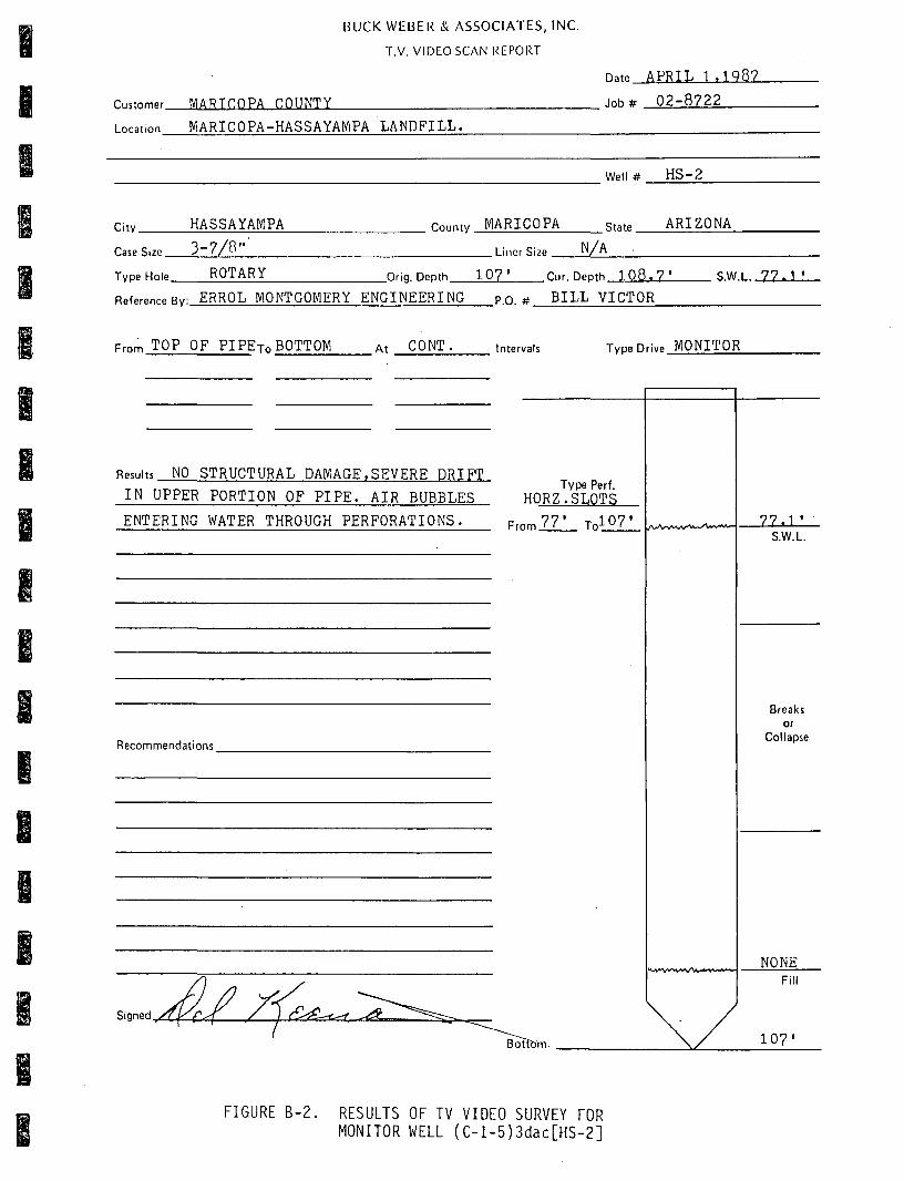
RESULTS OF TV VIDEO SURVEY FOR MONITOR WELL (C-l-5)3dac[HS-2]
RESULTS OF TV VIDEO SURVEY FOR MONITOR WELL (C-l-5)3ddal[HS-3]

BUCK WEBER & ASSOCIATES, INC.
T.V. VIDEO SCAN REPORT
rn.tnmpr WiARICOPA COUNTY
Location MARICOPA-HASSAYAMPA LANDFILL
n.tp APRIL 1 , 1 9 8 7
,„H^ 0 2 - 8 7 2 1
Well # HS-1
Citv HASSAYAMPA
r..P?;i.P 3 - 7 / 8 " I . D .
County MARICOPA State ARIZONA
Liner Size N /^
ROTARY _Orig. Depth 8 8 ' Cur. Deoth 8 8 ' S.W.L. 7 1 . 9 ' Type Hole
Reference RyiFRRni, MONTnOMFPY FNOTNFFRTNO PO # RTT.L VTCTOR
From TOP OF PIPETo BOTTOM TOP OF PIPE BOTTOM
.At CONT Intervals Tvoe Drive MONITOR
CONT.
Results NO STRUCTURAL DAMAGE,SOME DRIFT IN
WELL FROM 3 0 ' TO BOTTOM.
Recommendations
Signed. d ^ r - r . ^ . - ^ .
Type Perf. H O R Z . S L O T S
Frnm 8 3 - Tn 8 8 '
X
71 . 0 -S.W.L.
Breaks or
Collapse
NONE FIII
Bottom .asj
FIGURE B-1. RESULTS OF TV VIDEO SURVEY FOR MONITOR WELL (C-l-5)3daa[HS-l]
BUCK WEBER & ASSOCIATES, INC.
T.V. VIDEO SCAN REPORT
Cuunmer MARICOPA COUNTY
Location MARICOPA-HASSAYAMPA LANDFILL.
n.te A P R I L 1 . 1 9 8 7
. inh# 0 2 - 8 7 2 2
Well # H S - 2
Citv. HASSAYAMPA
Case Size 3 - 7 / 8 "
County MARICOPA state A R I Z O N A
Liner Size n / h
Type Hole. ROTARY _Orig. Depth 1 0 7 ' Cur. Depth 1 0 8 . 7 ' S W l 7 7 - 1 '
Reference Bv: ERROL MONTGOMERY ENGINEERING P.O. # BILL VICTOR
From TOP OF P I P E T O BOTTOM At CONT. intervals Type Drive MONITOR
Results NO STRUCTURAL DAMAGE.SEVERE DRIFT
IN UPPER PORTION OF P I P E . AIR BUBBLES Type Perf.
HORZ.SLOTS
ENTERING WATER THROUGH PERFORATIONS. FromlZJ_ T o l ^ Z l /V^^-v*^^v^^*"
Recommendations
Signed y ^ K ^ z : ^ ^ ^ ^.^g_
t^^i»%A/SV'./\/\A., V > ^ - |
Botf&m
77.1 ' S.W.L.
Breaks or
Collapse
NONE Fill
107'
FIGURE B-2. RESULTS OF TV VIDEO SURVEY FOR MONITOR WELL (C-l-5)3dac[HS-2]

BUCK WEBER & ASSOCIATES, INC.
T.V. VIDEO SCAN REPORT
Customer.
Location
MARICOPA COUNTY
MARICOPA-HASSAYAMPA LANDFILL.
n..te APRIL 1 .1987
, „ , ^ 02-8723
Well # HS-3
City. HASSAYAMPA County MARICOPA state ARIZONA
Case Si7e 3 - 7 / 8 " I . D . . Liner Size N/A
Type Hole. ROTARY _Orig. Depth. 9 8 ' Cur. Depth 9 8 . 9 ' S W l . 7 3 . V
Reference Rv: ERROL MONTGOMERY ENGINEERING p.p. # BILL VICTOR
From TOP OF PI PETO BOTTOM At CONT. intervals Tvoe Drive MONITOR
Results NO STRUCTURAL DAMAGE,SLIGHT DRIFT
IN UPPER PORTION OF PIPE,SLIGHT AMOUNT
OF AIR BUBBLES ENTERING WATER THROUGH
PERFORATIONS.
Type Perf. HORZ.SLOTS
Frnm 6 1 ' J , j Q ^
Recommendations
H.^*V».'^V*^*/W.v.«^-A*'
Bottom
7 3 - 5 ' S.W.L.
Breaks or
Collapse
NONE Fill
98'
FIGURE B-3. RESULTS OF TV VIDEO SURVEY FOR MONITOR WELL (C-l-5)3ddal[HS-3]

• a -a n 2 :
I—I X
o

I I I I I I I I I
APPENDIX C
LITHOLOGIC DESCRIPTION FOR DRILL CUTTINGS
Figure
C-l LITHOLOGIC DESCRIPTION FOR DRILL CUTTINGS FROM MONITOR WELL (C-1-5)3daa[HS-l] (FROM ARIZONA DEPARTMENT OF HEALTH SERVICES, 1985)
B C-2 LITHOLOGIC DESCRIPTION FOR DRILL CUTTINGS FROM MONITOR WELL (C-1-5)3dac[HS-2] (FROM ARIZONA DEPARTMENT OF HEALTH SERVICES, 1985)
I C-3 LITHOLOGIC DESCRIPTION FOR DRILL CUTTINGS FROM MONITOR WELL (C-1-
5)3ddal[HS-3] (FROM ARIZONA DEPARTMENT OF HEALTH SERVICES, 1985) C-4 LITHOLOGIC LOG FOR SOIL BORING (C-l-5)3dad[HW-B-l] (FROM ERTEC
WESTERN, INC., 1982]
C-5 LITHOLOGIC LOG FOR VADOSE ZONE MONITOR WELL (-l-5)3dda2[HW-B-2] (FROM ERTEC WESTERN, INC., 1982)
C-6 LITHOLOGIC LOG FOR VADOSE ZONE MONITOR WELL (C-l-5)3dbd[HW-B-3] (FROM ERTEC WESTERN, INC., 1982)

A n . sons bepsrtaenc oi neaxi;n o e m c e a Bureau of Waste Control LOO or TEST HOLtS
Siting Area ^ ^ ^ ^ ^ „ ^ ^ Tn.'S»nif nry ( a n d f i U
Ha$$avampa-Hazardou$ Waste Section
A.L. Roesler OATt
g/?i/ni OHaDNO CQUirutNT
Hayhew 1000-Rotory Drill Rlq
HOLC
UG-1
•TAl*
•uitrAcc ILCVATION
915.7
1
Hole Depth
Prom Pt.
0
5.0
7.0
13.0
14.0
15.0
18.5
19.5
25.0
To Pt.
5.0 •
7.0
13.0
14.0
15.0
18.5
19.5
25.0
47.0
t •
' •'Maricopa I 1
^.ponsor „,,^„p, Co. Hiqhway Deot. *'*" AZ
'"'"'•**"'Hassayampa Monitoring Well Installation
lOCAIION or MOUS f ^ Corner, Cast of Pit 3, 10' from fence
OtSCmPTTON or MATCRULt
Brown slltv gravelly ?and w/cobbles, drv, vp.ry
dense, little to moderate cementation
Brown silty clay, dry, brittle and friable.
w/callche nodules and moderate caliche cementation
Reddish brown clayey sand, dry, moderate caliche
cementation, root voids common
Grayish brown silty sand. dry. firm
Brownish gray silty sand w/flne gravel, dry, loose
Gray gravelly sand w/gravel stringers and lenses.
dry, loose
Gray sand, dry, loose
Brown clayey sand w/hard caliche lenses, dry.
very dense and difficult to excavate
Jrown gravelly silty sand, w/scattered cobbles.
Iry. moderate cementation
U S C
s *;«
CL
SC
SM
SP-
SP
SP
5C
SM
Standard Penetration Test Oata "N" Rlftw?
SH
tAMPlt* j
1 TYTC
rnOM' TO Inc.
rr. ' rr. % COMMEHT
1
I . DISTURBCIMINOItTURBIO-IIOClt COKC
FIGURE C-la.
t . COARSC MATCRIAI. KCMOYCD 1. rCRCCNT SAMPLE RCCOVtRY
LITHOLOGIC DESCRIPTION FOR DRILL CUTTINGS FROM MONITOR WELL (C-l-5)3daa[HS-l] (FROM ARIZONA DEPARTMENT OF HEALTH SERVICES, 1985)
•Hter 1 or y »Hiri

AriBona Department of Health Sendees Dureau of Waste Control t o o or I tST HOLtS
S i t i n g Area
iccAnoN
ICCCtO BY OATE
CmilllNQ IQUIPMENT
MOtt
\r,.\
• •
S T A : *
•UHfACt
mVATIOM
•
1
.
Hole ^ Depth Prom
P t .
47.0
55.0
68.0
76.0
101.0
111.0
To —Et*.
65.0
68.0
•
76.0
101.0
U l . O
120.0
i ; i t y / C o u n t y
i ip ona o r
|«JTt»«».
t l A T l
rnoitcT:
tOCATION o r MOLES
MscHtpnoN or MATCMIAIS
Brown ^ i l t v l c l a v . w/abundant cal iche cementation.
l i t t l e to no qravel
Black basal t , hard; may be a combination of
cemented cobbles and boulders as in a fanglomerate
along wi th seams of f low mater ia l .
Red sandy s i l t , w/scattered s i l t s tone seams •
Reddish brown c lay , w/scattered zones of gravel
as str ingers or lenses, wet
Reddish brown clayey gravel ly sand, saturated.
w/abundant f i ne gravel
Reddish brown s i l t y gravel ly sand, w/abundant -
angular to subrounded gravel , saturated.
Water Table 9 68.65' 9/24/81 •
\
•
u s c
CL
.
ML
CL
SP-
SP-
Standard 'enetrat ion Test Oata - t t " p l nw«
SC.
SM
u u n t t 1
nrf f r»ovl TO es t
rr. 1 rr.
1 1
% COMMENT
1
•
I . OtSTUMBnMJNOttTUBBRMtOCIt COBC
FIGURE C-lb.
I . COAItSC MATtDMl MtMOVtO J. f cRcerrr t A u n c Ricovtirr
LITHOLOGIC DESCRIPTION FOR DRILL CUTTINGS FROM MONITOR WELL (C-l-5)3daa[HS-l] (FROM ARIZONA DEPARTMENT OF HEALTH SERVICES, 1985)
•MttT or j M t r s

Arizona Dspartment of Heallh Services ftireau of Waste Control LOC or TEST HOLtS
Siting Area Maricopa County Sanitary Landfill ICCATION
Hassawamoa-Hazardous Waste Section
A.L. Roesler ""'9/23/81
Mayhew 1000-Rotary Drill Rig
NOtt
IM
oe-2
.
BTALA
BUHrACt
tlCVATION
915.5
,
t
»
Hole Depth
Prom Pt.
0
2.0
52.0
67.0
To Pt.
2.0
52.0
67.0
111.0
tity/County ISITIHO. Marlcooa 1 2
oponaor ^^^^^op, county Hiqhway Dept. *'*" Arizona"
Hassayampa Monitoring Well Installation LOCATION or MOLf s
Southern boundrv. across frran Ward Rd
DfSCBirnoN or MATCMUIB
Fill - silt, sand and 9ravel. drv, loose
Brown gravelly silty sand, w/thin seams of slltv
clay and clayey sand and stringers of sandy silt to
gravelly sand, dry, firm to dense
Black basalt; probable intercalated layers or
ieds of basaltic flow material, breccia,
agglomerate, cemented volcanic ash, and fanglomerate
:onsist1ng of caliche cemented basalt gravel.
:obbles and boulders; formation is very dense and
frilled slow but fairly smooth
led sandy silt, low plasticity, w/very fine to
Lo fine sand seams and scattered silty clay
stringers; scattered cemented fragments appear as
;1milar to siltstone; scattered cobbles throughout.
•
U S C
SM
.
L
Standard fenetration Test Oata "M- Rlnw«
SAMPltS 1
1
r rn rirou' TO
n. ' rr.
1
C.C
« COMMEHT
•
t . OlSTUBBtlMmtNtTUBBCtMIOeitCORC
FIGURE C-2a.
I . COAirSt WATtmAl BtMOVtO I . rCBCENT SAMPlC BECOVERV fMin or SHtri
LITHOLOGIC DESCRIPTION FOR DRILL CUTTINGS FROr-i MONITOR WELL (C-l-5)3dac[HS-2] (FROM ARIZONA DEPARTMENT OF HEALTH SERVICES, 1985)

Bureau of Wast e Control LOC o r TEST HOLES .
Si t ing Area ICCATtON
t e e s t o BY V
OATE
O m i U N O EOUll>MENT
NOlC M A
nfi.?
•
.
BT«:&
BunrACC
ClCVAnON
1
Hole Depth
From P t .
i i i . n
.
•
To _ P t .
120.0
•
t l l y / C o u n t y
Sponsor
I t i : : NO.
• » A I E
PROJECT:
lOCATIOM o r HOLES
eESCRimoN or MATCRUIB
Brown s i l t y gravel ly sand, w/abundant angular to
subrounded f i ne qravel. Water table 9 66.11'
9/24/81 24 hours af ter d r i l l i n g
•
•
•
•
U [standard S Penetration C
SP
Test Data "N» Rlnwc
SM
.
SAMPl tS
TYPE 'ROM* TO
rT. 1 rr.
L —
1
1
est.
H
COHHENT
I . 0(STURBEDmNDf<TURBCO4IOCK CORE 1 COARSC MATCRIAI REMOVCD I . PERCENT SAMPLE RECOVERY SHEET o r SMirrs
FIGURE C-2b, LITHOLOGIC DESCRIPTION FOR DRILL CUTTINGS FROM MONITOR WELL (C-l-5)3dac[HS-2] (FROM ARIZONA DEPARTMENT OF HEALTH SERVICES, 1985)

jureo
Sitim
u ur Hasce ConT;r01 LOC OF TEST HOLES
* *"• Maricooa Co. Sanitary landfill
Hajsavamoa-Hazardous Waste Section
"*""•' A.L. Roesler I"" 9/24/81 ORiiiiNBcouiPMENT^^^^ lOOO-Rotary Drill Rig
NOtC
NO.
W-3
.
•unrACC
tVCVATTON
010 4
1
Hole ^ Depth Proa Pt.
9
Z,0
39.0
68.0
89.0
104.0
112.0
TO Pt.
?.o
39.0
68.0
89.0
104.0
112.0
120.0
^"y^^°""'^y Maricopa ^ " ^ 3 kiponsor siATE
Marlcooa Co. Hiohwav Oeot. AZ PROJECT: ( jjjjyj j Monitoring Well Installation LOCATION or MOLES 5^ ^ ^ ^ ^ ^ ^
DCSCRtPTION or MATCRIAU
Fill, consisting of silt, sand and gravel
Brown silty sand, dense, well cemented w/caliche,
cobbles and hard caliche cementation * 25.0'
Black basalt, hard; fanglomerate w/c411che .
cementation appears to be dominant in the upper
Interval; small percentage of quartz and rhyolite
grains noted in cuttings
led sandy silt, low plasticity, w/very fine to
fine sand; scattered cemented fragments have the
sppearance of siltstone; w/scattered cobbles
Brown to red silty clay w/scattei-ed cobbles;
water bearing formation •
Brown clavev fine sand, soft
Brown silty qravelly sand, w/anqular to subrounded
fine gravel abundant. Water table 9 71.2' 9/25/81
U S C
SM
.
ffl.
:L
SP-
SP-
Standard Penetration Test Oata "N" Rlnw«
.
SC
SM
-
SAMPLES
1 TYPE
FROM' TO
rr. I rr.
'
1 1
CSC.
« COMMENT
18 hours after drilling 1. OltTURBCO-UWrnTURBCfMIOCK CORC i . COARSC MATCRtAL REMOVCO I . PERCENT SAMPLE RECOVERY SHEET 2 or 2 SMErS
FIGURE C-3. LITHOLOGIC DESCRIPTION FOR DRILL CUTTINGS FROM MONITOR WELL (C-l-5)3ddal[HS-3] (FROM ARIZONA DEPARTMENT OF HEALTH SERVICES, 1985)

A - 1
H i t
0 -
, SAUPLC r v p c
p f N C I R A l l O H O E N S l l V RfSlSTAHCC UOlStURC C O N S l S U N C v
I
.^, c
I
^
10-
15-
20-
25-
30-
35-
18
22
52
70
81
Slightly Moist
Medium OenM
Yellow Brown
SANO AND GRAVELLY SANO (SP-SM). tubangular to subrounded, fine to couns; variable gravel content up to 20%; gravel to ) t " recovered; weakly cemented below about 20 feet.
Very Dense
TQTAL DEPTH 30 FEET
ELEVATION: 908FEET OATE ORILLEO: 12/8/81
EQUIPMENT USED; 7" HOLLOW STEM AUGER WATER LEVEL; N O T ENCOUNTERED
a STAHOinO S P l l l SPOON S A M P l t A D m OENSIIY ILO/Cu F I I
lASTM D I S a « l
[ o ] CRTCC I I ' I " ORIVI SAMPtC
[ a ] SULK S A u p i c
m THIN w i l l TuaC SAMPIE l A s i u o i s t r i
riELO MOiSTunc i%on> M I I IAS1U D77I6I
NH HO nccovEov
^ErtBC m . g . » f c i ^ M i . t , c . t . M.I
HASSAYAMPA WfASTE/ PIPELINE STUDY
LOG OF BORING HW-B-I
Pro|.ct numbw 78-056-05 202. s Ertec
FIGURE C-4. LITHOLOGIC LOG FOR SOIL BORING (C-l-5)3dad[HW-B-l] (FROM ERTEC WESTERN,.INC., 1982)

A-2
F i l l
0 -
SAMPLE I YPE
P E N C i n A r i o N o E N S i i v f nESISIANCE UQISIURE CONSlSIEMCt
o Ca
,^
10-
15-
20-
Slightly Moist
52
23
59
84
Very Dense
Light Brown
CUYEY SANO (SC), fine to medium, medium plasticity; weakly cemented; trace of fine gravel.
Medium Dense
Red Brown
SANO AND GRAVELLY SANO (SW-SM), fine to course; weakly cemented below about 12 feet; some gravel to 3/8" recovered.
Very Dense
)
25—
30-
35—
TOTAL DEPTH 20.0 FEET
ELEVATION: 912FEET OATE DRILLED: 12/8/81 EQUIPMENT USED 7" HOLLOW STEM AUGER WATER LEVEL NOT ENCOUNTERED
S S T A N O A N O S P l l l SPOON SAMPLE A ODV DENSIIV ILO/CII F I I
lASIV l O t S t t I
[ o ] tRTCC J I O " DRi» t SAMPLE
[ a ] BULK SAMPLE
m l M N O A l l l ueE SAMPLE l A S H t O I M M
FIELO MOISTURE t « ORT W i t l A S I M o i r i s i
NR NO RECOVEHV
^E r tEC HASSAYAMPA WASTE/ PIPELINE STUOY
LOG OF BORING HW-B-2
Pfoi .et f iumb.# 76-OM-OS 1/B?
s ErtEC
FIGURE C-5. LITHOLOGIC LOG FOR VADOSE ZONE MONITOR WELL (C-i-5)3dda2[HW-B-2] (FROM ERTEC WESTERN, INC., 1982)

A - J
FCEI
0-
-SAMPLE ITPE
P C N E I R A I I O N nEHSiivi KESlSIAHCE HOISIURE CONSISIEHCf
10
- • -70
— I — .0
- t -
a.
' V ,
>
M
Vl
I
\
-I
10-
15 —
20—
25 — • ^ F
30-
35-
21
70
Slightly Moist
Stiff To Hard
Light Brown
SANDY CLAY-CLAYEY SANO (CL-SC). medium plasticity, predominantly fine sand size.
Medium Dense
Brown SILTY SANO (SM). fine weakly cemented.
Hard Red Brown
SANDY CLAY-CUYEY SAND (CL-SC), medium plasticity, fine to coana sand s i l l . tracB of gravel to 3/8" recovered; moderately to strongly cemented; layer of silty sand (SM) at 22' to 24*.
Very Dense
TOTAL DEPTH 23.7 FEET
(-o ELEVATION: 916FEET DATE DRILLED: 12/8/81 EOUIPMENT USED: 7" HOLLOW STEM AUGER WATER LEVEL: NOT ENCOUNTERED
a STANOARO SPLIT SPOON SAMPLE A DRT OEHSITV ILO'CU F Tl
lASTM D i s a a i
f p ] E K T t C I I ' J " DRIVE SAMPLE
( T ) »UIK SAMPLE
Q IHIN HALL lUaE SAMPLE lASTM O I M T I
A FIELD MOISTURE 1% D R f W I I ^ lASTM D l l l t l
NR HO RECOVERf
SsErtBC HASSAYAMPA WASTE/ PIPELINE STUOY
LOG OF BORING HW-B-3
P f o | « c t n u m b w 76 0 S « - O 5 >/»?
a Ertec
FIGURE C-6. LITHOLOGIC LOG FOR VADOSE ZONE MONITOR WELL (-l-5)3dbd[HW-B-3] (FROM ERTEC WESTERN, INC., 1982)