Embed Size (px)
Citation preview

Erosion and Sediment Control Guidelines for the Cook Islands
Prepared forInfrastructure Cook Islands
Prepared byTonkin + Taylor
DateAugust 2019
Job Number1009382

3Erosion and Sediment Control Guidelines for the Cook Islands
Table of Figures
(Place holder)
Appendix A: Example calculations
Appendix B: Standard drawings

4Erosion and Sediment Control Guidelines for the Cook Islands
Preface - Purpose and scope of this documentThis document provides technical guidance for erosion and sediment control (ESC) measures for earthwork activities in a Cook Island context. Earthwork activities covered in this document comprise:
• Vegetation removal and subsequent soil/ground disturbance for residential, commercial and infrastructure developments (including roads, utility trenches); and
• Earthworks associated with permitted Quarrying and Sand mining activities, such as overburden excavation and disposal.
The intended audience of this document are designers, contractors and other implementers who are responsible for operating and maintaining ESC measures for earthworks. This document also provides useful information for:
• Developers and designers, in planning of works which may have sediment impacts to the environment; and
• Regulatory officers, who assess and approve earth working activities where sediment impacts to the environment need to be managed.
Links and references to relevant technical resources are compiled in Section 6.
Clean waterWater that is free of sediment or pollutants. In the ESC context, this typically is the water from above a work site that has not run through the works area. This water could be in contained in streams or channels, or stormwater runon.
Construction staging Earthworks are undertake (or staged) over smaller areas in a site, with progressive revegetation to limit erosion
Decanting earth bund (DEB)
An area to temporarily store water, formed from a temporary bund or ridge of compacted earth. The bund provides an area where dirty water runoff can be ponded, and suspended sediment can settle out before runoff is discharged.
Dirty water Water that contains soil/sediment, and is typically discoloured. In the ESC context this usually water that requires treatment prior to discharge.
Discharge or Discharge point
The point where water (either clean or dirty) leaves the boundary of a site, and enters into streams, channels or ground beyond the boundary.
Erosion The process of wearing away the land surface by running water, wind and/or ice.
ESC Erosion and Sediment Control
ESC Designer The author of the Erosion and Sediment Control Plan
ESCP Erosion and Sediment Control Plan. Best practise would be to have this plan approved by a permitting authority prior to Works commencing
Receiving waters A natural water body or drainage feature that receives the site discharge
Runoff Surface flow of water that occurs when precipitation occurs (primarily rain).
Runon Surface flow of water that enters into a site boundary
Sediment control structures
Constructed ESC measures (e.g. DEB, SRP) that installed, monitored and maintained for the purpose of capturing eroded sediment
Sedimentation The process where sediment particles enter and move through the water column, typically accumulating at the bottom
Silt fence A temporary barrier of woven geotextile fabric that is used to capture mainly coarse sediments carried in sheet flow runoff. Silt fences provides impoundment and allows sediment to settle out of the water.
Site The extent and boundary of Works that is addressed by the ESCP
Site erodiability The amount of sediment generated by a site (with or without erosion controls). This depends on the erodibility of the soil, the energy of the rainfall and the site conditions (vegetation cover, slope, amount of earthworks)
Stabilised entrance
AA protected entry or exit point of a construction site. These points are typically stabilised through measures such large rocks and are designed to prevent site access points becoming sources of sediment, and/or assist in minimising dust generation and disturbance of areas adjacent to the road frontage by providing a defined entry and exit point.
Treatment The practise of constructing structural measures for sediment removal from water.
Works Activities requiring ESC practises. This typically comprises construction activities that remove vegetation to expose erodible soil, and/or disturbs the underlying soil
Terminology Terminology and acronyms used in this document are set out below. The first use of these terms and acronyms are highlighted bold in the subsequent sections.

5Erosion and Sediment Control Guidelines for the Cook Islands
1. Why is erosion and sediment control important
The Cook Islands has experienced an increase in land use and development, resulting in more construction earthworks being permitted and carried out.
Without measures to minimise erosion, the impact on fresh water and coastal environments can be significant.
Environmental effects associated with sediment release have been documented both globally, and for the Cook Islands. They include:
• Build-up of sediment in the stream bed
• Alteration of aquatic habitats (e.g. smothering spawning areas, changing light penetration, temperature change)
• Accumulation of pollutants transported by sediments (e.g. hydrocarbons, agricultural nutrients and toxic substances)
• Blocking water flows, increasing susceptibility to flooding and consequent damage to property
• Effects on water quality used for irrigation, stock and domestic water supplies (e.g. clogging of pumps, filters and sprinkle nozzles, increased water treatment required)
• Reduced appearance of water for recreational use (e.g. swimming, fishing)
• Physical changes to the stream channel and banks.
This document set outs a systematic approach for designing and implementing Erosion and Sediment Control (ESC).,The intention of effective ESC is to minimise erosion and the subsequent amount of sediment discharged from Works, which generate sediment. This document has been structured as follows:
Diagram 1.1 – Document flowchart
Why is erosion and sediment control important?
Steps to effective design and implementation
2. Principals of erosion
and sediment controls
1. Construction Site
Planning
2. Understanding Site
Hydrology
3. Understanding
Erosion and Sediment Control
4. Technical
references

6Erosion and Sediment Control Guidelines for the Cook Islands
2. Principles of erosion and sediment controls
2.1 Understanding erosionErosion and sedimentation are related processes. Erosion is the process of wearing away the land surface by running water, wind and/or ice. Through the erosion process, soil particles are dislodged and mobilised, generally from rainfall. The amount of sediment generated depends on the erodibility of the soil, the energy of the rainfall and the site conditions (referred hereafter as site erodabilitiy).
Typically, the steeper the site and the longer the flow lengths, the more energy will be created by rainfall flowing across the ground, and sediment is more likely to be generated. Modifying site conditions (e.g. excavating and loosening soil, removing vegetation covering) increases the site erodabilty, and further increases the likelihood of sediment generation.
Once soil particles are dislodged, sedimentation is the process where these particles enter and move through the water column, typically accumulating at the bottom (refer Figure 2.1).
2.1.1 GeologyThe Cook Islands are the result of volcanic activity andcoral growth (ref 1). Rarotonga is the largest of the CookIslands, and has been broadly classified into three zones:
• Coastal margins, comprising the estuarine and beachridges;
• Flood plains, on slopes typically less than 5 degrees; and
• Interior fans, terraces and upland hilly and steep land(moderately sloping to steep).
A typical geological cross section for Rarotonga isillustrated below (refer Figure 2.2).
Based on this cross section, and supporting informationcontained in the soil survey report (ref 2), erodible soils re present at Rarotonga and likely to be exposed during vegetation removal and/or earthworks (even shallow
earthworks). Unless basaltic rock is being exposed,most soils are likely to be susceptible to natural erosion.These soils could range from yellow beach sands (for thebeach ridge areas) to alluvial and colluvium silts and claydeposits of brown, grey/dark grey and red in colour (inthe flood plains and interior land).
The loosening of these soil through human activitiessuch has earthworks has the potential to furtherincrease its erodability and result in sedimentation. Wellimplemented erosion controls can reduce this increase.
Specific geological information for the outer islandsis not available. Unless specific planning and/orinvestigations demonstrates site erodabiltiy will notincrease because of the Works, planning of Works mustconsider erosion controls.
Figure 2.1 The erosion andsedimentation process
Erosion
Sedimentation
Soil (Non-erodable)
Soil (Erodable)
The adverse environmental effects resulting from this process (refer Section 1) are the reasons to understand what influence soil erosion, and implement effective ESC during activities that can increase the site erodability.
Figure 2.2: Diagrammatic cross-section of Rarotonga Reproduced from NZ Soil Survey Report 49: Soils of Rarotonga Cook Islands, NZ Soil Bureau (1980).

7Erosion and Sediment Control Guidelines for the Cook Islands
2.1.2 Climate The Cook Islands experiences a tropical climate with two seasons:
• Wet season: Typically November to May, characterised by high humidity, sudden downpours, strong winds and tropical cyclones (hurricanes).
• Dry season: Typically June to October, characterised by cooler temperatures.
In the Northern Cooks Islands, the temperature can remain mostly constant throughout the year, while in the Southern Cooks (including Rarotonga and Aitutaki) there is slight difference between the wet (warmer) and dry (cooler) months.
Climate outlooks and forecasts provide valuable guidance for construction planning, as they can guide start and duration of Works.
Climate outlooks and forecasts are available on The Cook Islands Meteorological Service website: https://www.met.gov.ck/
Works should always be timed to start in periods of forecasted dry weather (i.e. no rain). If Works cannot be completed within the same period of dry, ESC measures are required unless it is demonstrated that site erodability will not increase because of the Works.
2.2 Understanding SedimentationErosion control is the most effective way to minimisethe effects from sedimentations. However in mostcases, increasing of site erodability cannot becompletely eliminated and some sedimentation willoccur (as sedimentation results when erosion occurs).
The sedimentation process can be managed to reduceits impacts through artificial structures (sedimentcontrols) which allow eroded soil in dirty water to be“trapped” before being carried into receiving waterswhich have human and environmental value (refer Figure 2.3).
Vegetation is the most effective form of erosioncontrol, in preventing or reducing erodabilty of soilsurfaces. Vegetation provides a shield to the energyof falling rain, slows the velocity of rainfall runoff,holds soil particles together, and increases thecapacity of soil to absorb water. While Works areoccurring, artificial shields can be created using mulch,geotextiles or similar to temporarily cover the ground.Once complete, the ground cover should be replacedeither through paving, or re-grassing where otherwiseexposed soil would remain.
For Works that include removal of existing vegetationground cover (e.g. grass), planning of the Works mustconsider erosion controls.
Figure 2. 3 – Water treatment concept
Figure 2. 3
DirtyWater
Settling Zone
Sludge Zone
Soil particle settles to the sludge zone
*Dashed lines are imaginary
V
V
Inlet Zone
Outlet Zone
CleanWater
2.1.3 Ground cover Vegetation is the most effective form of erosion control, in preventing or reducing erodabilty of soil surfaces. Vegetation provides a shield to the energy of falling rain, slows the velocity of rainfall runoff, holds soil particles together, and increases the capacity of soil to absorb water. While Works are occurring, artificial shields can be created using mulch, geotextiles or similar to temporarily cover the ground. Once complete, the ground cover should be replaced either through paving, or re-grassing where otherwise exposed soil would remain.
For Works that include removal of existing vegetation ground cover (e.g. grass), planning of the Works must consider erosion controls.

8Erosion and Sediment Control Guidelines for the Cook Islands
2.3 Construction planning Construction planning is an important part of understanding how Works can be carried out to maximum erosion control and minimise sediment control.
Earthworks carried out over the entire site maximises the time and area that soil is exposed and prone to erosion. Construction staging is useful for large projects. This involves completing earthworks in smaller areas, with progressive revegetation to limit erosion, reducing the level of sediment control necessary.
Construction planning shall consider:• How Works are sequenced. This can be done
through illustrative sketches showing the construction steps.
• Duration and timing of Works, including timing of ground cover is removed and subsequently replaced.
• Site erodability, and level of ESC required.
• Site specific considerations e.g.
- Protecting steep slopes, either through avoiding ground cover clearance, or by diverting water around cleared slopes
- Protecting waterbodies within the site, by establishing “no-go” zones for vegetation clearance.
• The risk to all waterbodies and public drainage infrastructure within and around the Site, in particular
- How can site discharges enter streams
- How can site discharges enter public drainage infrastructure
Construction planning shall also consider how temporary stockpiles, site access and utility service installation are managed so not to increase site erodability. Covering stockpiles, maintaining designated access points, and timing of service installation to dry weather are examples of how this could be achieved.
The construction planning considerations and the Works sequencing shall be set out in a site specific Erosion and Sediment Control Plan (ESCP).
The ESC designer (i.e. the author of the ESCP) shall be suitability experienced and able to:
• Understand the nature of Works and assess site erodability accordingly
• Set out the construction planning
• Select and design ESC measures in accordance with this guideline
• Supervise and monitor the implementation of ESC in accordance with the approved ESCP and relevant permit requirements.
The subsequent sections have been prepared to guide the ESC designer, and provide a framework of minimum requirements for a permitting authority to approve the ESCP.
Image to come

9Erosion and Sediment Control Guidelines for the Cook Islands
3. Erosion and sediment control (ESC) design
3.1 Understanding site hydrology It is important to quantify the amount of water entering into (runon), and running off from a site (runoff) when selecting appropriate ESC.
To assess site hydrology for an ESC context, the following must first be determined:
• Duration of works =
- Less than 1 month
- 1 to 6 months
- More than 6 months
• Catchment Area =
Site Area (A s, in hectares)
+ Upstream Catchment entering site (A u-in, in hectares)
+ Upstream Catchment diverted around site (A u-out, in hectares)
• ESC design Area A esc =
Catchment Area – A u-out
3.1.1 Acceptable rainfall riskA design storm can be defined to achieve a set level of protection for the protection of downstream water bodies. Typically, the 20 year ARI event is adopted as the design storm in an ESC context. However, Works with shorter duration has reduced exposure (and so susceptibility) to soil erosion, and a lower design storm may be acceptable (refer Figure 3.1), though this must be balanced by the sensitivity of receiving waters.
The following provides guidance for the ESC designer to determine the design storm for Works of varying durations:
• Less than 1 month: no less than the 1 year event
• 1 to 6 months: 2 – 10 year event, depending on sensitivity of receiving waters.
• More than 6 months: 10 -20 year event, depending on sensitivity of receiving waters
3.1.2 Estimating design runoff The rational method provides a simple empirical model suitable for estimating peak flow from storm water runoff (refer Eq. 1) and is widely accepted in New Zealand applications for runoff flow estimations.
Eq. 1:
Where: Q = Peak discharge (m³/s)
C = Runoff coefficient (see section 4.3.1.2)
i = Rainfall intensity (mm/hour)
A = Area of catchment (hectares)
Rainfall intensity is a function of the time of concentration (i.e. the shortest time for water to travel over the longest path within your site). For small sites typically < 0.5 ha (5,000 m2), a 10 min time of concentration is appropriate in most cases. For larger sites, the ESC designer shall calculate a site-specific time of concentration. High intensity rainfall data (e.g. HIRDs, or similar) is used to determine the rainfall intensity which corresponds to the time of concentration.
Q= CiA360
Note: HIRDs data for Cook Is-lands is under development. It is recommended the NewZealand HIRDs or Australianequivalent for regions ofcomparable climate is adopted in the interim (refer Section 7). For ESC design, climate changefactors may be ignored.
Figure 3.1: Rainfall probability graph (based on New Zealand data)

10Erosion and Sediment Control Guidelines for the Cook Islands
3.1.2 Estimating design runoff cont...Table 3.1 provides values for typical runoff coefficients (C) by soil type. A high level understanding of site soil and its erodability is recommended before selecting an appropriate C value. For large sites, multiple C values may be appropriate. In this case, Area (A) in Eq. 1 should be adjusted to reflect the extent that the C-value would apply to.
Table 3.1: Runoff co-efficient ‘C’
Runoff Co-efficient by soil type
Topsoil 0.4
Flat sand (<5°) 0.15
Flat bare silt (<5°) 0.3
Moderately sloping bare silt (10-20°) 0.4
Moderate sloping bare clay (<10°) 0.65
Steep bare clay (>10°) 0.75
Gently sloping grass cover (<10°, sand or clay)
0.1 – 0.2
Steep steep bush 0.6
A design runoff estimate is required for sizing the following ESC measures:• Cleanwater diversion drains (refer section 4.1):
Use A u-out in Eq. 1
• Dirty water diversion drains (refer section 5.1): Use Aesc Eq. 1
Worked example: Step 1: Assess acceptable risk
Works duration: 1 month in October (dry season)
Receiving water sensitivity: Stream -> Coastal Lagoon; High
Design storm: 5 year (18% chance of exceedance, considered acceptable)
Step 2: Estimate design run off
Site extents: 50 m wide x 100 m long, so site area = 5000 m2, 0.5 ha
For 0.5 ha, adopt time of concentration (tc) of 10 min.
For tc of 10 min, design storm of 5 year, rainfall intensity i (refer Figure 3.1) = 75 mm/hr
Figure 3.1: NZ HIRDs data table from Northland (considered to have comparable climate)
Site soils = sand, C = 0.15 (from Table 3.1)
Run-off to size dirty water channel
= C x i x Aesc /360
= 0.15 x 75 x 0.5/360
= 0.015 m3/s

12Erosion and Sediment Control Guidelines for the Cook Islands
Stockpiled material for site without sediment controls
Covered rainfall protection to site materials
Erosion controls act to limit the amount of sediment eroded.As discussed above, construction planning should placeemphasis on erosion control to minimise the mobilisation ofsediment. By this, less sediment is required to be capturedand treated through the control measures compared torelying solely on sediment control.
Effective erosion control is about reducing the energyof runon water to dislodge sediment and/or providinggreater protection to “shield” soil from it energy. This isachieved through:
• Minimising the volume and velocity of water entering, and subsequently existing the site; and
• Maintaining or providing a protective layer against soil erosion through existing vegetation or using soil stabilisation techniques.
For most activities, a combination of both techniques will need to be applied. Specific guidance on these techniques are set out below.
13Erosion and Sediment Control Guidelines for the Cook Islands
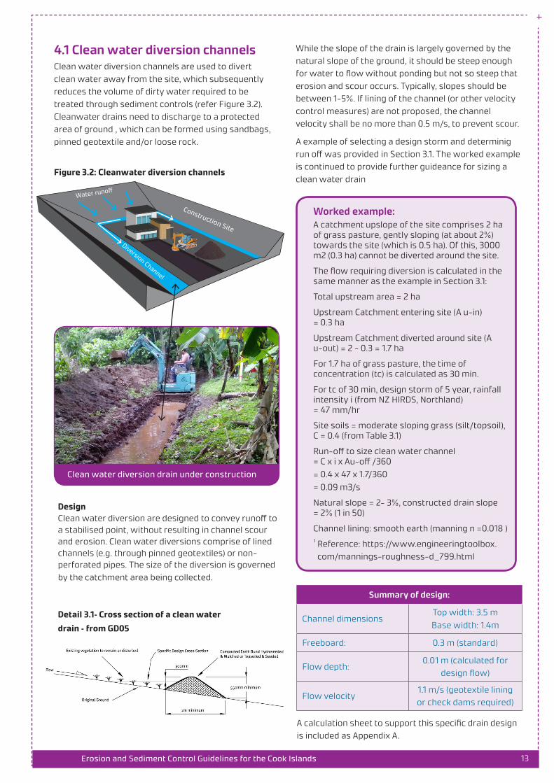
4.1 Clean water diversion channelsClean water diversion channels are used to divertclean water away from the site, which subsequentlyreduces the volume of dirty water required to betreated through sediment controls (refer Figure 3.2).Cleanwater drains need to discharge to a protectedarea of ground , which can be formed using sandbags,pinned geotextile and/or loose rock.
Figure 3.2: Cleanwater diversion channels
Water runoff
Construction Site
Diversion Channel
Clean water diversion drain under construction
Design Clean water diversion are designed to convey runoff to a stabilised point, without resulting in channel scour and erosion. Clean water diversions comprise of lined channels (e.g. through pinned geotextiles) or non-perforated pipes. The size of the diversion is governed by the catchment area being collected.
Detail 3.1– Cross section of a clean water
drain – from GD05
While the slope of the drain is largely governed by the natural slope of the ground, it should be steep enough for water to flow without ponding but not so steep that erosion and scour occurs. Typically, slopes should be between 1-5%. If lining of the channel (or other velocity control measures) are not proposed, the channel velocity shall be no more than 0.5 m/s, to prevent scour.
A example of selecting a design storm and determinig run off was provided in Section 3.1. The worked example is continued to provide further guideance for sizing a clean water drain
Worked example: A catchment upslope of the site comprises 2 ha of grass pasture, gently sloping (at about 2%) towards the site (which is 0.5 ha). Of this, 3000 m2 (0.3 ha) cannot be diverted around the site.
The flow requiring diversion is calculated in the same manner as the example in Section 3.1:
Total upstream area = 2 ha
Upstream Catchment entering site (A u-in) = 0.3 ha
Upstream Catchment diverted around site (A u-out) = 2 - 0.3 = 1.7 ha
For 1.7 ha of grass pasture, the time of concentration (tc) is calculated as 30 min.
For tc of 30 min, design storm of 5 year, rainfall intensity i (from NZ HIRDS, Northland) = 47 mm/hr
Site soils = moderate sloping grass (silt/topsoil), C = 0.4 (from Table 3.1)
Run-off to size clean water channel = C x i x Au-off /360= 0.4 x 47 x 1.7/360= 0.09 m3/s
Natural slope = 2- 3%, constructed drain slope = 2% (1 in 50)
Channel lining: smooth earth (manning n =0.018 )
¹ Reference: https://www.engineeringtoolbox.com/mannings-roughness-d_799.html
Summary of design:
Channel dimensions Top width: 3.5 mBase width: 1.4m
Freeboard: 0.3 m (standard)
Flow depth:0.01 m (calculated for
design flow)
Flow velocity 1.1 m/s (geotextile lining or check dams required)
A calculation sheet to support this specific drain design is included as Appendix A.

14Erosion and Sediment Control Guidelines for the Cook Islands
4.2 Check dams Check dams are small temporary dams constructed across an open drain or small water channel, usually comprise of multiple in series. Their primary purpose is to slow down water velocity and prevent channel scour and may be used for drain catchments less than 1 ha. Where catchments exceed 1ha, drain lining should be adopted.
As a rule of thumb, flow velocities exceeding 0.5 m/s in sand, or 1 m/s in clay are likely to cause scour.
They are made from non-erodible material such as, sandbags and loose rocks (rip-rap).
A series of rock check dams
A temporary sandbag check dam – Auckland GDO5
DesignCheck dams are typically constructed with either 450 or 600 mm high centres, the maximum height of check dams should be 200 mm below the top of the channel. The spacing of the check dams is dictated by the slope of the channel; a steep slope will have faster flows and require more dams to reduce velocity.
Table 3.1
Detail 3.2
Worked example: A temporary clean water diversion drain is required for 2 weeks to divert water over a 6% slope. The clean water drain has already been sized for the catchment area; 1.2 m wide and 0.6 m in height, and needs to be 20 m long. The flow velocity is much higher than 0.5 m/s and channel scour is considered likely.
Lining the channel is an expensive option as the channel will only be required for 2 weeks. Instead, check dams created from sandbags are proposed.
• Step 1: Check Dam height. The centre dam height must be lower than the channel height, the channel height is 600 mm (0.6m) so 450 mm is selected as the check dam height.
• Step 2: Spacing between Check dams. The slope of the channel is 6% and the height is 450 mm. From Table 3.1, the required spacing between dams is 5 m. As our slope length is 20 m this would require 4 check dams (20 / 5). If 0 m is the start of the slope and 20 m is the end, the dams would be located at 5m, 10m, 15m and 20m.

15Erosion and Sediment Control Guidelines for the Cook Islands
4.3 Stabilised entranceways A stabilised entranceway is designed to stop site access ways becoming sources of sediment. They are located at any entry and exit points to the construction site. Design of a stabilised entryway need to consider:
• Location of permanent entry/exit points;
• Length of the entrance way; and
• The expected daily traffic volumes.
Design
Wheel wash to remove sediment from tires
A grid to remove sediment from tires
Detail 3.3
Detail 3.4
Table 3.2
Worked example: The earthworks site is close to the main village and construction vehicles will be using the main road to get to and from site. This activity is likely to track mud and dirt along the main road and result in complaints from the community.
A stabilised entrance will reduce the quantity of mud and dirt leaving the site and being tracked on the main road.
The size of the stabilised entranceway is constrained by the site conditions, however the minimum distances can be met (shown in the table above).

16Erosion and Sediment Control Guidelines for the Cook Islands
4.4 Soil surface stabilisationA site that can reduces the area of exposed soil is one that has reduced its erodabilty, and is sometimes necessary.
• For large sites, greater than 2 ha;
• Where implemented sediment control are not proving effective.
Techniques to stabilise (or provide temporary ground cover) include grassing, mulching and geotextile placement.
4.4.1 Grassing Grass and vegetation is often the simplest way to achieve stabilisation. However, it is only effective if good grass strike is achieved with at least 80% coverage, so it is important to time the seeding with the seasons and achieve good seed coverage. Grassing is primarily used as a medium to long term solution.
4.4.2 Mulching This involves covering the disturbed soil with a layer of mulch which includes wood pulp, hay, bark and straw creates a protective layer over the soil. Mulching is primarily used to achieve rapid stabilisation for a short to medium term solution.
Initial hydro seeding and slope planting
Hay mulching next to stream
Well struck hydroseed
Bark mulching, retaining moisture for plants

17Erosion and Sediment Control Guidelines for the Cook Islands
4.4.3 Geotextile placementhis involves placing and pinning geotextile fabric over the top of the disturbed soil. Once applied this control will immediately reduce the erodability of disturbed soil. This can be a short term, or long term (semi-permanent) solution depending on the geotextile chosen.
Geotextile fabrics cover a range products. Biodegradable geotextiles provide temporary erosion protection allowing time for vegetation to establish itself before breaking down into the environment. Non-biodegradable geotextiles should be removed after their use, they are typically used to stabilise short steep slopes, on batters and stockpiles.
Biodegradable coconut matting Non-biodegradable geotextile
Worked example: Earthworks for a new house site have been conducted at the end dry season but the new house will not be built until after the wet season. During the wet season, sediment will be washed from the site and enter the nearby stream, if the soil is left exposed.
The soil surface should be stabilised to prevent rainfall washing away the soil. As the site will not be worked on for another 6 months, grass stabilisation is chosen to achieve this. Grass will take approximately 6-8 weeks to establish. So a temporary cover is required to protect the soil while the grass establishes. A biodegradable matting or 50 mm layer of mulch can be used. In this case, the mulch is readily available and the matting is not, so mulch has been chosen.
Solution: Apply grass seed to the soil, and covering with a thin layer of mulch to protect the seed as the grass strike is established.

19Erosion and Sediment Control Guidelines for the Cook Islands
Sediment controls act to remove sediment once it has been dislodged and mobilised in rainfall runoff. Sediment controls must be applied before dirty water runoff leaves a site and enters receiving waters.
Effective sediment controls focuses on the two keys aspects of sedimentation transportation:
• Capture and convey dirty water to sediment control structures; and
Earthworks (which increase site erodibility) carried out without sediment controls
Site fence to control dirty water from slope earthworks
• Reduce its velocity to allow enable sedimentation to occur at these sediment control structures.
The amount of sediment control required is governed by the ESC design area (Aesc), and a larger area will always result in a greater amount of sediment control necessary. Sediment controls should always be applied with erosion control methods outlined earlier in this guidance.

20Erosion and Sediment Control Guidelines for the Cook Islands
5.1 Dirty water conveyance Dirty water drains are used to collect and carry dirty water (runoff with sediment) from a site area to an appropriate sediment treatment pond. Dirty water drains are normally constructed across a slope, at a grade of 2% and discharge to a treatment structure (sediment retention pond, or decanting earth bund)
Dirty water drains are typically unlined, unless notable scouring of the drain base is observed.
Example of a dirty water drain
Design • Drain are often constructed from a combination of
a back or bund with the excavation upslope, or an earthen back constructed from compacted earth (refer Detail 4.1 on the following page)
• For larger sites areas (typically >2ha, 20,000 m2) or drains steeper than >2% (1 in 50), the same design process for cleanwater drain sizing shall be carried out for dirty water drains.
• Where possible, choose a route to the sediment treatment device that avoids trees, infrastructure, fence lines and other features
• Like clean water drains, dirty water drains must 300 mm freeboard.
Once implemented, if scour of the drain invert is observed on more than 3 occasions, or compromises the drain function (e.g. allows water to escape), geotextile lining or check dams should be considered.
Detail 4.1 – Standard cross section of dirty water drain
Table below is produced for a U channel, 0.6 m width, allowing for 0.3 m freeboard (approximate standard detail
A calculation sheet to support this design check is included as Appendix A.
Slope Design depth Design flow capacity Design flow capacity Comments
1 in 50 (2%) 0.08 0.024 m/s 1.0 m/s Standard detail
1 in 16.7 (6%) 0.08 0.041 m/s - ok 1.8 m/s – not okVelocities too high.
Need specific design
Worked example: A catchment upslope of the site comprises 2 ha of grass pasture, gently sloping (at about 2%) towards the site which is 0.5 ha. Of this, 3000 m2 (0.3 ha) cannot be diverted around the site. The site area falls at 6% grade (3.5°), and it is not practical to construct a dirty water drain at a shallower grade.
Dirty water drains are sized in the same manner as clean water diversion drains.
Total upstream area = 2 ha
Upstream Catchment entering site (A u-in) = 0.3 ha
Upstream Catchment diverted around site (A u-out) = 2 - 0.3 = 1.7 ha
ESC design Area A esc
= Site Area + A u-in
= 0.5 + 0.3 = 0.7 ha
For 0.7 ha of bare earth (silt) the time of concentration (tc) is calculated as 10 min.
For tc of 10 min, design storm of 5 year, rainfall intensity i (from NZ HIRDS, Northland) = 75 mm/hr
Site soils = flat bare silt (<5°), C = 0.3 (from Table 3.1)
Run-off to size dirty water channel
= C x i x Au-off /360
= 0.3 x 75 x 0.7/360
= 0.04 m3/s
Constructed drain slope = 6% (1 in 16.7, or 3.5°)
Channel lining: smooth earth (manning n =0.018 )
Check against hydraulic performance for the standard cross-section detail:
21Erosion and Sediment Control Guidelines for the Cook Islands
The size of an SRP is based on the ESC design area which contributes to that specific SRP (Aesc -x), and the slope of surrounding ground. A maximum of 3 ha can be treated by a single SPR.
As guidance: • For sites with slopes less than 10% grade the main bay
size is a 200 m3 per ha
• For sites with slopes greater that 10% the main bay should 300 m3 per ha
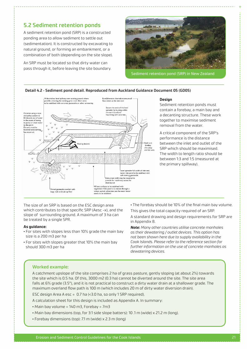
5.2 Sediment retention ponds A sediment retention pond (SRP) is a constructed ponding area to allow sediment to settle out (sedimentation). It is constructed by excavating to natural ground, or forming an embankment, or a combination of both (depending on the site slope).
An SRP must be located so that dirty water can pass through it, before leaving the site boundary.
Sediment retention pond (SRP) in New Zealand
Design Sediment retention ponds must contain a forebay, a main bay and a decanting structure. These work together to maximise sediment removal from the water.
A critical component of the SRP’s performance is the distance between the inlet and outlet of the SRP which should be maximised. The width to length ratio should be between 1:3 and 1:5 (measured at the primary spillway).
Detail 4.2 – Sediment pond detail. Reproduced from Auckland Guidance Document 05 (GD05)
Worked example: A catchment upslope of the site comprises 2 ha of grass pasture, gently sloping (at about 2%) towards the site which is 0.5 ha. Of this, 3000 m2 (0.3 ha) cannot be diverted around the site. The site area falls at 6% grade (3.5°), and it is not practical to construct a dirty water drain at a shallower grade. The maximum overland flow path is 100 m (which includes 20 m of dirty water diversion drain).
ESC design Area A esc = 0.7 ha (<3.0 ha, so only 1 SRP required).
A calculation sheet for this design is included as Appendix A. In summary:
• Main bay volume = 140 m3, Forebay = 7m3
• Main bay dimensions (top, for 3:1 side slope batters): 10 .1 m (wide) x 21.2 m (long).
• Forebay dimensions (top): 7.1 m (wide) x 2.3 m (long)
• The forebay should be 10% of the final main bay volume.
This gives the total capacity required of an SRP.
A standard drawing and design requirements for SRP are in Appendix B.
Note: Many other countries utilise concrete manholes as their dewatering / outlet devices. This option has not been shown here due to supply availability in the Cook Islands. Please refer to the reference section for further information on the use of concrete manholes as dewatering devices.

22Erosion and Sediment Control Guidelines for the Cook Islands
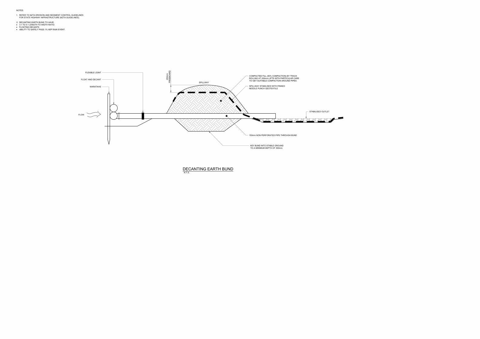
5.3 Decanting earth bundsA decanting earth bund (DEB) is ponding area constructed from a temporary compacted earth bund. A DEB has the same function as SRP, however is only appropriate for treating up to 3000 m2 (0.3 ha). DEB’s purpose is to reduce the amount of sediment contained within runoff before leaving the work site.
DEB from – Ecan ESC 2007
DEB shall remain until the contributing catchment has been stabilised.
Design• A pipe should pass through the DEB to allow clean
water to discharge downstream.
• The inlet of the pipe should be 150mm lower than the spillway.
• The maximum catchment area contributing to a DEB should not exceed 0.3 ha. DEBs shall be sized
Detail 4.3 – Decanting earth bund. Reproduced from Environment Canterbury Guidelines (Ecan ESC 2007)
Worked example: A new stockpiling area is required for excavated soil. A flat area of 2000 m2 is available adjacent to the site, and is proposed to hold the stockpile material, but also to park dirty machinery at the end of each working day. A DEB is proposed at the lowest point of the site to provide treatment of the full area.
ESC design Area A esc = 0.2 ha (2000 m2)
DEB volume = 30/100 x 2000
= 60 m3
DEB Area = 60 m3/ 1.2 m
= 50 m2
Dimensions = 7.1 m x 7.1 m (assuming a square shape)
to store 30 m3 for every 100 m2 (0.1 ha) of the catchment.
• The DEB should be no more than 1.2 m deep
The cross section and elevation drawings below, illustrates the key design parameters for a decanting earth bund.

23Erosion and Sediment Control Guidelines for the Cook Islands
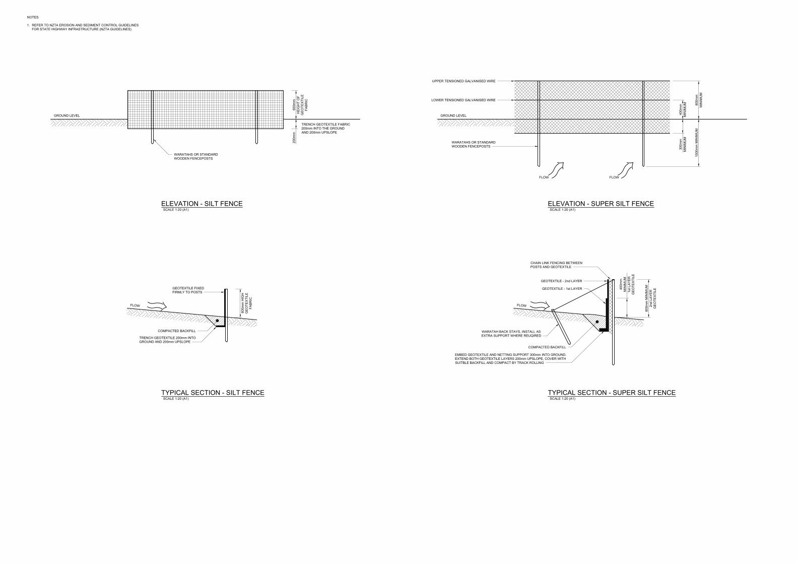
5.4 Silt fencesSilt fences act as temporary barriers to capture coarse sediment carried by surface water. Silt fences slow down the water and allow the sediment to settle out of the water. Silt fences are best used for containing stockpiles of earth or for areas where site runoff tends to spread out, and cannot be captured by a dirty water drain.
Silt fence with warratahs
Silt fence with timber pegs
DesignSilt fences should be:
• Minimum of 600 mm high above ground and 200 mm below
• Maximum post spacing of 2 m
• Have returns every 20 - 60m along the length of the Silt fence depending on the slope
Using Table 4.1, the slope is 5%, so a row of silt fence is required for each 40 m length of slope. The slope length for the stockpile area is 20 m, so only one row of fence is necessary.
Using Table 4.1, 2m returns are required for every 60 m length of fence that is perpendicular to the slope. Returns are not required (only 25 m is perpendicular).
Detail 4.4 – Silt fence schematic from Auckland ESC for building on small site
Table 4.1
Worked example:A large quantity excavated material needs tobe stockpiled in an area 20 m by 20 m on a 5%slope for a couple of months until it can beused at another site for fill. This soil is likelyto erode and cause uncontrolled sedimentto enter the road drainage system. The roaddrainage goes to the marine lagoon area, andcan impact the marine environment.
A silt fence can be installed around thestockpile area to stop the soil and sedimentmoving towards the drainage inlet. The silt fence should completely surround the stock-piled material on three sides (there is no need for a silt fence upslope of the stockpile as thesediment will only move downwards). This willrequire a total of 75 m of silt fence of which 25m is perpendicular to the slope (refer Sketch 3)
25m
25m
20m
20mSilt fence
Silt fence
Stockpile
Stockpile
PLAN
CROSS-SECTIONA B
A B
5%
Sketch 3 - Example for a silt fence design
24Erosion and Sediment Control Guidelines for the Cook Islands
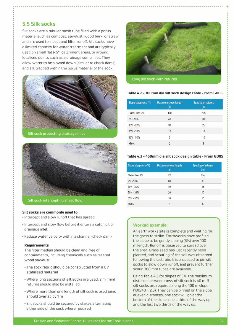
5.5 Silk socksSilt socks are a tubular mesh tube filled with a porus material such as compost, sawdust, wood bark, or straw and are used to incept and filter runoff. Silt socks have a limited capacity for water treatment and are typically used on small flat (<5°) catchment areas, or around localised points such as a drainage sump inlet. They allow water to be slowed down (similar to check dams) and silt trapped within the porus material of the sock.
Silt sock protecting drainage inlet
Long silt sock with returns
Silt sock intercepting sheet flow
Silt socks are commonly used to:• Intercept and slow runoff that has spread
• Intercept and slow flow before it enters a catch pit or drainage inlet
• Reduce water velocity within a channel (check dam)
Requirements The filter median should be clean and free of containments, including chemicals such as treated wood sawdust
• The sock fabric should be constructed from a UV stabilised material
• Where long sections of silt socks are used, 2 m (min) returns should also be installed.
• Where more than one length of silt sock is used joins should overlap by 1 m
• Silt socks should be secured by stakes alternating either side of the sock where required
Table 4.2 – 300mm dia silt sock design table - from GD05
Table 4.3 - 450mm dia silt sock design table – From GD05
Worked example: An earthworks site is complete and waiting for the grass to strike. Earthworks have profiled the slope to be gently sloping (3%) over 100 m length. Runoff is observed to spread over the area. Grass seed has just recently been planted, and scouring of the soil was observed following the last rain. It is proposed to pin silt socks to slow down runoff, and prevent further scour. 300 mm tubes are available.
Using Table 4.2 for slopes of 3%, the maximum distance between rows of silt sock is 40 m. 3 silt socks are required along the 100 m slope (100/40 = 2.5). They can be pinned on the slope at even distances; one sock will go at the bottom of the slope, one a third of the way up and the last two thirds of the way up.

25Erosion and Sediment Control Guidelines for the Cook Islands
6. Supplementary drainage structures
6.1 Pipe drop structures and flumes The sections above set out the design open channel drains, which are largely the same for cleanwater and dirtywater purposes. A pipe drop or flume is a drainage structure that allows water to be carried down steep slopes, without causing erosion of the slope. They are typically established on slopes steeper than 1V:3H., and is used in conjunction with diversions channels (either clean or dirty), as outlined earlier in the document (i.e. drain comes into it at the top, and a second drain collects the water at the bottom). These structure may be constructed as a temporary or permanent fixtures depending on their application
Typically, the steeper the site and the longer the flow lengths, the more energy will be created by rainfall flowing across the ground, and sediment is more likely to be generated. Modifying site conditions (e.g. excavating and loosening soil, removing vegetation covering) increases the site erodabilty, and further increases the likelihood of sediment generation.
Once soil particles are dislodged, sedimentation is the process where these particles enter and move through the water column, typically accumulating at the bottom (refer Figure 2.1).
Temporary pipe drop (flexible pipe)
Permeant concrete flume let down
Design
Detail 5.1 - pipe drop and flume schematic taken from GD05
26Erosion and Sediment Control Guidelines for the Cook Islands
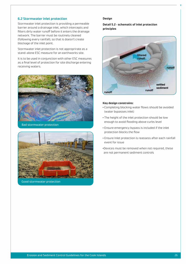
6.2 Stormwater inlet protection Stormwater inlet protection is providing a permeable barrier around a drainage inlet, which intercepts and filters dirty water runoff before it enters the drainage network. The barrier must be routinely cleaned (following every rainfall), so that is doesn’t create blockage of the inlet point.
Stormwater inlet protection is not approprirate as a stand-alone ESC measure for an earthworks site.
It is to be used in conjunction with other ESC measures as a final level of protection for site discharge entering receiving waters.
Bad stormwater protection
Good stormwater protection
Design
Detail 5.2 – schematic of inlet protection principles
Key design constrains: • Completing blocking water flows should be avoided
(water bypasses inlet)
• The height of the inlet protection should be low enough to avoid flooding above curbs level
• Ensure emergency bypass is included if the inlet protection blocks the flow
• Ensure Inlet protection is reassess after each rainfall event for issue
• Devices must be removed when not required, these are not permanent sediment controls

27Erosion and Sediment Control Guidelines for the Cook Islands
Worked example: Treated water runoff from the SRP (Aesc –x =0.7) needs to go down a steep slope (approx. 15%) that is 10 m long, before it can discharge into a drainage inlet. The steep slope will cause the water to scour and get dirty again. If dirty water is discharged to the drainage inlet, it will enter the lagoon.
As the slope is greater than 10% check dams are not an appropriate. A pipe drop or flume channel is proposed, with the bottom located at the road channel.
Step 1: Select from a pipe or a flume option.
As the site area is less than 1 ha, both a pipe or flume can be used (if it was larger than only a flume could have been chosen). HDPE lining is available on site so a flume is selected.
Step 2: Design the flume size.
The width of the flume should be 1.5 m per ha of catchment area: 1.5 x 0.7 = 1.1 m in width
The depth of the flume is a minimum of 0.3 m.
The length of the flume should cover be the entire slope length plus a 1 m at the inlet and 1m at the outlet. The total flume length is 10 + 1 + 1 = 12 m.
Over this length the liner should be pinned either size of the flume every 0.5 m down the entire length.
Step 3: Inlet and outlet protection A stabilised inlet is required as per Detail 5.1 above.
A stabilised outlet is also required to protect the drainage channel from scour as water exists the flume. Placing sandbags or loose rock over 1m of lining will achieved this. As a final level of protection, silt socks are placed around the adjacent drainage sump for stormwater inlet protection.

28Erosion and Sediment Control Guidelines for the Cook Islands
7. Guidance for Permit Authorities

29Erosion and Sediment Control Guidelines for the Cook Islands
8. Further technical resources
8.1 Weather Cook Island Meteorological Services
https://www.met.gov.ck/
8.2 Technical Reports Soils of Rarotonga, Cook Islands
http://digitallibrary.landcareresearch.co.nz/cdm/ref/collection/p20022coll4/id/91
Soil map of Rarotonga, Cook Islands (Available from ICI)
8.3 Design Guidance Compliance Document for New Zealand Building Code, Clause E1 Surface Water (2017)
https://www.building.govt.nz/assets/Uploads/building-code-compliance/e-moisture/e1-surface-water/asvm/e1-surface-water-1st-edition-amendment10.pdf
Manning’s roughness Co-efficients
https://www.engineeringtoolbox.com/mannings-roughness-d_799.html
New Zealand HIRDs: https://www.niwa.co.nz/information-services/hirds
Australian Design rainfall service: http://www.bom.gov.au/water/designRainfalls/revised-ifd/
8.4 ESC guidelines from New Zealand Erosion and Sediment Control Guide for Land Disturbing Activities in the Auckland Regionhttp://content.aucklanddesignmanual.co.nz/regulations/technical-guidance/Documents/GD05%20Erosion%20and%20Sediment%20Control.pdf
Erosion and Sediment Control Guidelines for the Wellington Region
http://www.gw.govt.nz/assets/Resource-Consents/Erosion-and-sediment-control-guidelines-2002.PDF
Erosion and Sediment Control Guidelines for Land Disturbing Activities, Environment Bay of Plenty
https://www.boprc.govt.nz/media/29555/Guideline-100624-ErosionandSedimentControl.pdf
Environment Canterbury Regional Council Erosion and Sediment Control Website
https://www.esccanterbury.co.nz/yourproject/
Building on small sites, doing it right. Erosion and Sediment controls for small site in Auckland
https://www.aucklandcouncil.govt.nz/building-and-consents/understanding-building-consents-process/starting-building-renovation-work/Documents/bc5850-building-small-sites-brochure.pdf

30Erosion and Sediment Control Guidelines for the Cook Islands
Appendix A: Example calculations
Project03 Trapezoidal channel__________________________________________________________________________
19/07/2019Page 1 of 1
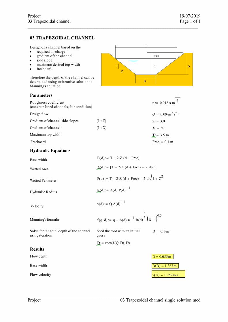
03 TRAPEZOIDAL CHANNEL
Z
1 d D
B
Free
TDesign of a channel based on therequired discharge ·gradient of the channel·side slope·maximum desired top width·freeboard.·
Therefore the depth of the channel can bedetermined using an iterative solution toManning's equation.
Parameters
Roughness coefficient (concrete lined channels, fair condition)
n 0.018 s m
1-
3:=
Design flow Q 0.09 m3
s1-
:=
Gradient of channel side slopes (1 : Z) Z 3.0:=
Gradient of channel (1 : X) X 50:=
Maximum top width T 3.5 m:=
Freeboard Free 0.3 m:=
Hydraulic Equations
B d( ) T 2 Z d Free+( )-:=Base width
A d( ) T 2 Z d Free+( )- Z d+[ ] d:=Wetted Area
P d( ) T 2 Z d Free+( )- 2 d 1 Z2
++:=Wetted Perimeter
R d( ) A d( ) P d( )1-
:=Hydraulic Radius
v d( ) Q A d( )1-
:=Velocity
Manning's formula f q d, ( ) q A d( ) n1-
R d( )
2
3 X
1-( )0.5-:=
Solve for the total depth of the channelusing iteration
Seed the root with an initialguess
D 0.1 m:=
D root f Q D, ( ) D, ( ):=
Results
Flow depth D 0.055m=
Base width B D( ) 1.367 m=
Flow velocity v D( ) 1.059m s1-
=
___________________________________________________________________________Project 03 Trapezoidal channel single solution.mcd

GDB - Flow in U channels - Mannings___________________________________________________________________________
19/07/2019Page 1 of 2
02 U CHANNEL FLOW
dD
B
B/2
Determine the hydraulic characteristics ofa U channel. The cross section consistsof a semi circular invert and verticalstraight sides above this.
An efficient cross section minimises theslope required to carry a given flow. Thisis provided by minimising the wettedperimeter (frictional resistance) for a crosssectional area of flow. Slope of channel (1 : x)
Units L 103-m
3:=
Parameters
Design freeboard Free 300mm:=
Channel depth Genrally D = B this allows thechannel to be defined with a singledimension
Roughness coefficient (n) n 0.018 s m
1-
3:=
Mannings Equation
Velocity of flow V d B, x, ( ) θ 2 acos 12 d
B-
dB
2<if
π otherwise
AB
2
8θ sin θ( )-( )
dB
2<if
π B2
8d
B
2-
B+
otherwise
PB θ
2d
B
2<if
π B
22 d
B
2-
+
otherwise
RA
P
s1
x
1
nR( )
2
3 s( )
1
2
:=
_________________________________________________________________________Swire SITA Waste Services Limited 02 Mannings U channel.mcd

NWNT & GDB Landfills RestorationGDB - Flow in U channels - Mannings___________________________________________________________________________
19/07/2019Page 2 of 2
Flow Q d B, x, ( ) θ 2 acos 12 d
B-
dB
2<if
π otherwise
AB
2
8θ sin θ( )-( )
dB
2<if
π B2
8d
B
2-
B+
otherwise
A V d B, x, ( )
:=
Results
Base width of channel B 600mm:=
Hydraulic design depth d D B
D Free-
:= d 0.3 m=
Slope x 100:= V d B, x, ( ) 1.568m s1-
=
Q d B, x, ( ) 0.222m3.000
s1.000-
=
Slope x 75:= V d B, x, ( ) 1.811m s1-
=
Q d B, x, ( ) 0.256m3.000
s1.000-
=
Slope x 50:= V d B, x, ( ) 2.218m s1-
=
Q d B, x, ( ) 0.314m3.000
s1.000-
=
Slope x 20:= V d B, x, ( ) 3.507m s1-
=
Q d B, x, ( ) 0.496m3.000
s1.000-
=
Slope x 10:= V d B, x, ( ) 4.96 m s1-
=
Q d B, x, ( ) 0.701m3.000
s1.000-
=
_________________________________________________________________________Swire SITA Waste Services Limited 02 Mannings U channel.mcd
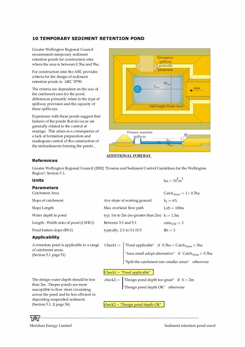
10 TEMPORARY SEDIMENT RETENTION POND
Lmid
h
BS1
Wmid
Emergencyspillwaygeotextileprotection
Primary manholespillway
Inlet
Mid height Water level
hlive
hdead
Greater Wellington Regional Councilrecommends temporary sedimentretention ponds for construction siteswhere the area is between 0.3ha and 5ha.
For construction sites the ARC providescriteria for the design of sedimentretention ponds in ARC TP90.
The criteria are dependent on the size ofthe catchment area for the pond.differences primarily relate to the type ofspillway provision and the capacity ofthese spillways.
Experience with these ponds suggest thatfailures of the ponds that do occur aregenerally related to the control ofseepage. This arises as a consequence ofa lack of formation preparation andinadequate control of the construction ofthe embankments forming the ponds.
ADDITIONAL FOREBAY References
Greater Wellington Regional Council (2002) "Erosion and Sediment Control Guidelines for the WellingtonRegion", Section 5.1.
Units ha 104m
2:=
Parameters Catchment Area CatchArea 1 0.7 ha:=
Slope of catchment Ave slope of existing ground S1 6%:=
Slope Length Max overland flow path LoS 100m:=
Water depth in pond typ. 1m to 2m (no greater than 2m) h 1.5m:=
Length : Width ratio of pond (LWR:1) Between 3:1 and 5:1 ratioLW 3:=
Pond batters slope (BS:1) typically. 2:1 to 3:1 H:V BS 3:=
Applicability
A retention pond is applicable to a rangeof catchment areas.(Section 5.1 page 51)
Check1 "Pond applicable" 0.3ha CatchArea< 3haif
"Area small adopt alternative" CatchArea 0.3haif
"Spilt the catchment into smaller areas" otherwise
:=
Check1 "Pond applicable"=
The design water depth should be lessthan 2m. Deeper ponds are moresusceptible to flow short circulatingacross the pond and be less efficient indepositing suspended sediment.(Section 5.1, l) page 56)
check2 "Design pond depth too great" h 2m>if
"Design pond depth OK" otherwise
:=
check2 "Design pond depth OK"=
__________________________________________________________________________________________
Meridian Energy Limited Sediment retention pond.xmcd

Project: MunroDescription: 0.33 haComputed:EDB
Job No:83208.012WBS:
Checked:
September 2011
Volume of Main bay pond
Volume of pond (minimum)Guidelines provide minima criteria basedon the slope of the catchment
Vpond CatchArea 2%( )m S1 10%<( )if
CatchArea 3%( )m otherwise
:=
Minimum pond volume to meet the criteria Vpond 140 m3
=
For sandy soils (less than 8% clay and less than 40% silt) the pond volumemay be calculated using the formula:
pond surface area = 1.5 peak inflow rate (5% AEP). Ensure that the pond·has a minimum depth of 1m. Calculate the inflow rates using HIRD(high intensity rainfall data).
Dimensions of Main bay pond
A trapezoidal cross-section is the most common form of section for aretention pond. This section results from the use of earth embankments toretaining the pond. The dimensions are determined based on a rectangularpond of trapezoidal cross section in both directions.
Area of pond (at mid-depth) Amid Vpond h1-
:= Amid 93.333 m2
=
Width of pond (at mid-depth) Wmid
Amid
ratioLW:= Wmid 5.6 m=
Length of pond (minimum at mid-depth) Lmid ratioLW Wmid:= Lmid 16.7 m=
Base dimensions: Wbase Wmid BS h-:= Wbase 1.1 m=
Lbase Lmid BS h-:= Lbase 12.2 m=
Top of water surface dimensions Wtop Wmid BS h+:= Wtop 10.1 m=
Ltop Lmid BS h+:= Ltop 21.2 m=
Atop Wtop Ltop:= Atop 214 m2
=
Forebay DesignVfore CatchArea 0.1%( )m S1 10%<( )if
CatchArea 0.3%( )m otherwise
:=Volume of forebay (minimum)Guidelines provide minima criteria basedon the slope of the catchment (Section 5.1, a) & i) pages 52 & 55)
Minimum forebay volume to meet the criteria.Vfore 7 m
3=
Total volume of ppnd & forebay Vtot := Vpond + Vfore Vtot = 147 m3
____________________________________________________________________________________
Project: MunroDescription: 0.33 haComputed:EDB
Job No:83208.012WBS:
Checked:
September 2011
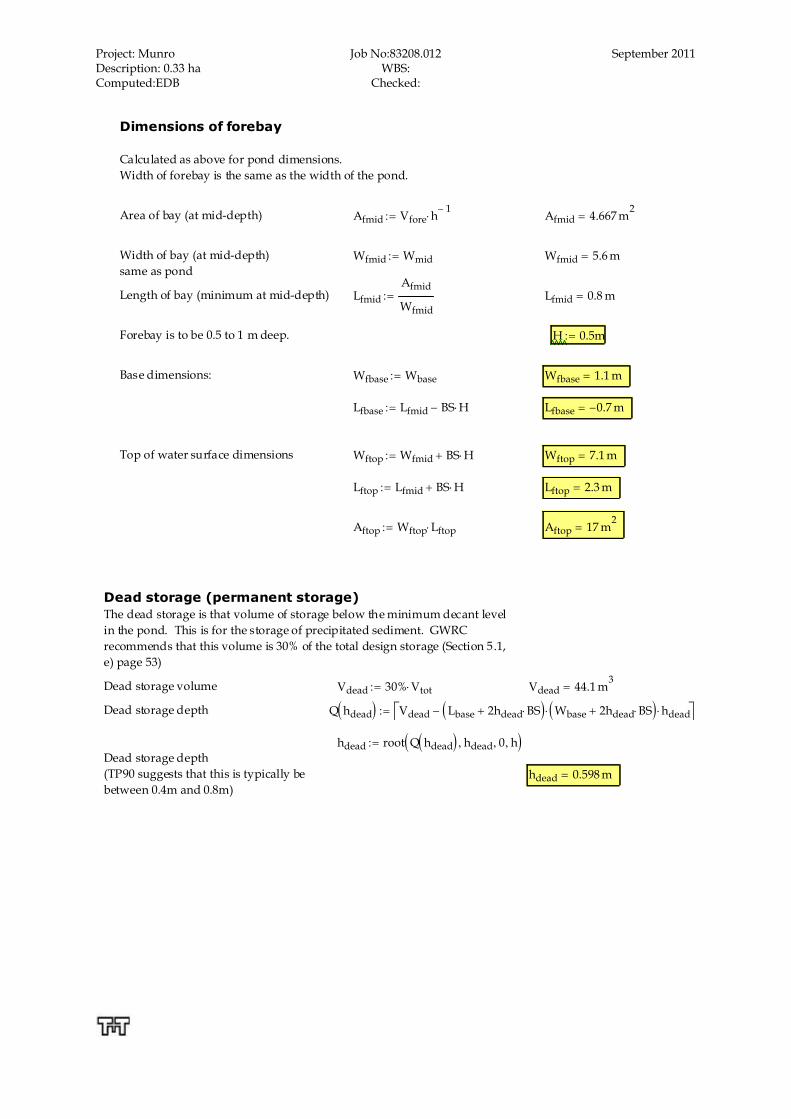
Dimensions of forebay
Calculated as above for pond dimensions. Width of forebay is the same as the width of the pond.
Area of bay (at mid-depth) Afmid Vfore h1-
:= Afmid 4.667 m2
=
Width of bay (at mid-depth)same as pond
Wfmid Wmid:= Wfmid 5.6 m=
Length of bay (minimum at mid-depth) Lfmid
Afmid
Wfmid:= Lfmid 0.8 m=
Forebay is to be 0.5 to 1 m deep. H 0.5m:=
Base dimensions: Wfbase Wbase:= Wfbase 1.1 m=
Lfbase Lfmid BS H-:= Lfbase 0.7- m=
Top of water surface dimensions Wftop Wfmid BS H+:= Wftop 7.1 m=
Lftop Lfmid BS H+:= Lftop 2.3 m=
Aftop Wftop Lftop:= Aftop 17 m2
=
Dead storage (permanent storage)The dead storage is that volume of storage below the minimum decant levelin the pond. This is for the storage of precipitated sediment. GWRCrecommends that this volume is 30% of the total design storage (Section 5.1,e) page 53)
Dead storage volume Vdead 30% Vtot:= Vdead 44.1 m3
=
Dead storage depth Q hdead( ) Vdead Lbase 2hdead BS+( ) Wbase 2hdead BS+( ) hdead- :=
hdead root Q hdead( ) hdead, 0, h, ( ):=Dead storage depth (TP90 suggests that this is typically bebetween 0.4m and 0.8m)
hdead 0.598 m=

30Erosion and Sediment Control Guidelines for the Cook Islands
Appendix B: Standard drawings

WIDE SHALLOW LEVEL SPILLWAY OVER
EXISTING GROUND WHERE POSSIBLE,
RETAINING THE EXISTING GRASS COVER.
MINIMUM WIDTH 6m. BARE AREAS TO BE
STABILISED WITH CONCRETE, TWO LAYERS
OF GEOTEXTILE OR OTHER ARMOURING
SEDIMENT FOREBAY
(1m DEEP AND 2m WIDE)
LEVEL SPREADER FULL WIDTH OF INLET
END, BATTER INTO POND TO BE STABILISED
WITH SOFT MATTING GEOTEXTILE
EXTRA CREST WIDTH MAY BE REQUIRED
TO PROVIDE FOR MACHINERY ACCESS
FOR CLEANING OUT
ALL BARE SURFACES TO BE STABILISED
WITH VEGETATION IF THE POND IS TO
REMAIN THROUGH A WINTER PERIOD,
OTHERWISE JUST THE OUTER BATTER
NEEDS TO BE STABILISED
BUND/DIVERSION CHANNELS
TO ENSURE ALL FLOW
ENTERS AT THE INLET END
SECURE THE ENDS OF THE LEVEL
SPREADER BY BURYING WITHIN
THE EARTH BUND AND
HAUNCHING WITH CONCRETE
PINNED GEOTEXTILE OVERLAID WITH
LARGE ROCK TO BREAK UP FLOW
N.T.S.
SCHEMATIC - SEDIMENT RETENTION POND
N.T.S.
SECTION - SEDIMENT RETENTION POND FOR THREE DECANTS
POURED CONCRETE ANTI-SEEP COLLAR
300mmØ DISCHARGE PIPE LAID
AT 1 TO 2% GRADIENT
POURED CONCRETE ANTI-SEEP COLLAR
POND BATTERS 2:1 TO 3:1
SPILLWAY COMPACTED AND SMOOTHED TO
ELIMINATE ALL VOIDS PRIOR TO LAYING AND
PINNING APPROPRIATE GEOTEXTILE/CONCRETE
WIDTH OF TOP EMBANKMENT SHOULD BE WIDE ENOUGH TO
ENSURE MACHINERY ACCESS FOR DE-SLUDGING OF POND,
IF THERE ARE NO OTHER ACCESS POINTS AVAILABLE
MIN
IM
UM
F
RE
EB
OA
RD
3
00
mm
30
0m
m
UPPER DECANT
OPERATES OVER TOP 1/3
OF LIVE STORAGE ONLY
LOWER DECANT OPERATES
OVER FULL DEPTH OF LIVE
STORAGE UP TO 1500mm
MIDDLE DECANT
OPERATES OVER TOP 2/3
OF LIVE STORAGE ONLY
500mm
DEAD STORAGE
CONCRETE RISER MAY REQUIRE
WEIGHTING OR ANCHORING TO
PREVENT FLOATING
LOWEST INLET PIPE TO RISER IS
ANGLED UPWARD AT 15° TO EASE
TENSION ON FLEXIBLE JOINT
WARATAH STAKES REQUIRED
FOR ALL DECANTS
NOTES
1. REFER TO NZTA EROSION AND SEDIMENT CONTROL GUIDELINES FOR STATE HIGHWAY
INFRASTRUCTURE (NZTA GUIDELINES)
2. PRIOR TO SEDIMENT RETENTION POND CONSTRUCTION:
· CHECK GROUND CONDITIONS TO ENSURE STABLE AND GEOTECHNICAL ASSESSMENT OCCURS.
· CONFIRM DESIGN IS NOT IN THE FLOOD PLAIN.
· INSTALL SILT FENCE OR SUPER SILT FENCE BELOW WORKS AREA.
· REMOVE UNSUITABLE MATERIAL AND CONFIRM APPROPRIATE LOCATION.
B
20
0m
m6
00
mm
HE
IG
HT
O
F
GE
OT
EX
TIL
E
FA
BR
IC
TRENCH GEOTEXTILE FABRIC
200mm INTO THE GROUND
AND 200mm UPSLOPE
GROUND LEVEL
WARATAHS OR STANDARD
WOODEN FENCEPOSTS
SCALE 1:20 (A1)
ELEVATION - SILT FENCE
SCALE 1:20 (A1)
TYPICAL SECTION - SILT FENCE
60
0m
m H
IG
H
GE
OT
EX
TIL
E
FA
BR
IC
FLO
W
GEOTEXTILE FIXED
FIRMLY TO POSTS
TRENCH GEOTEXTILE 200mm INTO
GROUND AND 200mm UPSLOPE
COMPACTED BACKFILL
10
00
mm
M
IN
IM
UM
40
0m
m
MIN
IM
UM
GROUND LEVEL
WARATAHS OR STANDARD
WOODEN FENCEPOSTS
SCALE 1:20 (A1)
ELEVATION - SUPER SILT FENCE
UPPER TENSIONED GALVANISED WIRE
LOWER TENSIONED GALVANISED WIRE
80
0m
m
MIN
IM
UM
30
0m
m
MIN
IM
UM
FLOW FLOW
SCALE 1:20 (A1)
TYPICAL SECTION - SUPER SILT FENCE
40
0m
m
MIN
IM
UM
1st L
AY
ER
GE
OT
EX
TIL
E
GEOTEXTILE - 2nd LAYER
EMBED GEOTEXTILE AND NETTING SUPPORT 300mm INTO GROUND.
EXTEND BOTH GEOTEXTILE LAYERS 200mm UPSLOPE, COVER WITH
SUITBLE BACKFILL AND COMPACT BY TRACK ROLLING
80
0m
m M
IN
IM
UM
2n
d L
AY
ER
GE
OT
EX
TIL
E
GEOTEXTILE - 1st LAYER
CHAIN LINK FENCING BETWEEN
POSTS AND GEOTEXTILE
WARATAH BACK STAYS, INSTALL AS
EXTRA SUPPORT WHERE REUQIRED
FLO
W
COMPACTED BACKFILL
NOTES
1. REFER TO NZTA EROSION AND SEDIMENT CONTROL GUIDELINES
FOR STATE HIGHWAY INFRASTRUCTURE (NZTA GUIDELINES)
FLOAT AND DECANT
WARATAHS
FLEXIBLE JOINT
25
0m
m
FR
EE
BO
AR
D
SPILLWAY
SPILLWAY STABILISED WITH PINNED
NEEDLE PUNCH GEOTEXTILE
STABILISED OUTLET
COMPACTED FILL (90% COMPACTION) BY TRACK
ROLLING AT 200mm LIFTS WITH PARTICULAR CARE
TO GET SUITABLE COMPACTION AROUND PIPES
150mm NON PERFORATED PIPE THROUGH BUND
KEY BUND INTO STABLE GROUND
TO A MINIMUM DEPTH OF 300mm
N.T.S.
DECANTING EARTH BUND
FLOW
NOTES
1. REFER TO NZTA EROSION AND SEDIMENT CONTROL GUIDELINES
FOR STATE HIGHWAY INFRASTRUCTURE (NZTA GUIDELINES)
2. DECANTING EARTH BUNS TO HAVE:
· 3:1 TO 5:1 LENGTH TO WIDTH RATIO
· FLOATING DECANTS
· ABILITY TO SAFELY PASS 1% AEP RAIN EVENT.

AGGREGATE (50-100mm WASHED)
CARRIAGEWAY
NOT TO SCALE
PLAN - STABILISED VEHICLE ENTRANCEWAY
NOT TO SCALE
SECTION - STABILISED VEHICLE ENTRANCEWAY
CARRIAGEWAY
150mm THICKNESS OR 1.5 x AGGREGATE SIZE
GEOTEXTILE
SITE ACCESS
OR HAUL ROAD
NOTES
1. REFER TO NZTA EROSION AND SEDIMENT CONTROL GUIDELINES
FOR STATE HIGHWAY INFRASTRUCTURE (NZTA GUIDELINES)

N.T.S.
SECTION - CLEAN WATER DIVERSION TYPE B
N.T.S.
SECTION - DIRTY WATER DIVERSION
2:1 OR FLATTER
COMPACTED EMBANKMENT
3:1 OR FLATTER
ORIGINAL GRADE
30
0m
m
DE
SIG
N F
LO
W D
EP
TH
EXISTING VEGETATION RETAINED
2H
1V
E
X
I
S
T
I
N
G
S
L
O
P
E
0.5H
1V
P
R
O
P
O
S
E
D
C
U
T
F
A
C
E
COMPACTED TOPSOIL BUND
ALONG THE CONTOUR
N.T.S.
SECTION - CLEAN WATER DIVERSION TYPE A
N.T.S.
SECTION - CLEAN WATER DIVERSION TYPE C
EXISTING VEGETATION RETAINED
E
X
I
S
T
I
N
G
S
L
O
P
E
0.5H
1V
PROPOSED CUT
FLOW ALONG THE CONTOUR
S
O
M
E
F
L
O
W
D
O
W
N
T
H
E
S
L
O
P
E
GEOFABRIC MATERIAL (SILT
FENCE OR SIMILAR) FIXED TO
REINFORCED WARATAHS
E
X
I
S
T
I
N
G
S
L
O
P
E
F
L
O
W
D
O
W
N
T
H
E
S
L
O
P
E
COMPACTED TOPSOIL BUND (MIN
0.3m HEIGHT) TO KEEP DIRTY WATER
SEPARATE FROM CLEANWATER
PROPOSED FILL
CLEANWATER CHANNEL INSTALLED AS FILL
RISES. CHANNEL BASE AND SIDE LINED
WITH GEOTEXTILE IF SCOURING OBSERVED
EXISTING VEGETATION RETAINED
1H
12V
EXPECTED ROCK
CUT FACE
CUT EARTHWORKS SHALL SHAPE AND
MAINTAIN A CHANNEL AS THE CUT IS
PROGRESSED AND THE CUT IS STABILISED
(E.G. SOIL NAILS, EXPOSED ROCK)
MULCH OR SLASH BUND (WHERE
AVAILABLE) AS REQUIRED TO REDUCE
FLOW VELOCITIES. FIXED TO SLOPE
USING WARATHS AND WIRE OR SIMILAR
SOME FLOW ALONG THE CONTOUR
3H
1V
WATER LEVEL
NOTES
1. REFER TO NZTA EROSION AND SEDIMENT CONTROL GUIDELINES
FOR STATE HIGHWAY INFRASTRUCTURE (NZTA GUIDELINES)
2. DESIGN DIMENSIONS SUBJECT TO SPECIFIC DESIGN WITHIN
CWMP AND SITE SPECIFIC MANAGEMENT PLAN DETAILS.