Embed Size (px)
Citation preview

ERIKS Sealing Technology Polymer Components for Automotive and Transportation

2 Contents
Through rigid application of process and quality control we are able to offer our customers the consistent reliable product demanded in safety critical applications.Lee Murray Operations ManagerERIKS Sealing Technology
Unitised PTFE lip seal for high speed shaft operation and easy installation.

3
Contents
All information in this documentation has been compiled with care to ensure accuracy. Despite this we can bear no liability for error and/or changes in legislation that may affect content. Recommendations are intended as guidelines only, for further information and technical assistance, please consult your Applications Engineer.
Freon, Viton and Vamac are trademarks of Dupont. Stellite is a trademark of Deloro Stellite Company Inc. Aflas is a trademark of Asahi Glass
Shore® is a registered trademark of Instron Corporation Hydrin® is a registered trademark of Zeon Corporation
© No part of this publication may be reproduced without clear reference to the source. All rights expressly reserved by ERIKS.
CaPabILITIES 04
MaTERIaLS 08
Elastomers 08
Chemical compatibility chart 17
aPPLICaTIonS 18
PRodUCTS 28
Elastomeric Rotary Lip Seals 28
PTFE Rotary Lip Seals 32
Unitised Seals 36
Technical and Installation Information 40
GS Split Seals 46
R70 Fabric Located Heavy Duty Rotary Seals 47
O-Rings 48
X-Ring 50
Typical Applications 52
Capped O-ring 54
Double Acting Cap Seal 56
T-Seal 58
Energised Lip Seal 60
Asymmetric U-Cup 62
Single Acting Cap Seal 64
Exclusion Devices / Wiper Rings 66
Machines Wear Ring / Bearing Strip 68
Bearing Strip 70
addITIonaL PRodUCTS and SERvICES 74

4 Introduction
Quality Control and assurance are the foundations upon which ERIKS Sealing Technology builds its offering of high-performance products into transportation applications. Pioneer Weston is the premium brand of ERIKS Sealing Technology. after more than 80 years Pioneer Weston remains at the forefront of sealing technology offering continued innovation in both material development and product design.
Leader in Sealing Technology
Pioneer Weston originated from the
partnership of two British manufacturers,
Charles Weston, a supplier of Elastomer
and Leather seals into high performance
industries, and the prominent Pioneer
Oilseals; supplier of Static and Rotary
seals into the automotive industry. This
strong collaboration helped to make
Pioneer Weston a global leader in both
the Automotive and General Industrial
markets, offering a wide range of sealing
products. Whilst the product portfolio
has evolved, the core principals of the
business remain the same, offering
engineered sealing systems that have
gained an enviable reputation for quality
and performance in some of the world’s
most demanding applications.
ERIKS Sealing Technology supplies a
range of O-ring and technical rubber
mouldings in compounds specifically
tailored to the needs of the transportation
industry. The Pioneer Weston product
range consists of Elastomer and PTFE
Rotary seals, and bespoke Mechanical
seals. The Pioneer Weston Rotary seal
style suffixes of R4, R6, R21 and R23
have become a recognised standard to
engineers specifying rotary seals - a true
testament to the impact the company has
made on global industry.
Experienced Application Engineers draw
upon in-depth technical knowledge to
ensure that the optimal seal is impartially
specified for your application; whether
this is a standard product from our
premium manufacturing facilities, or
as a bespoke solution tailored to your
needs. ERIKS design teams work closely
with our material scientists to produce
accurate materials data upon which our
non-linear finite element analyses (FEA)
are based, to minimise design iterations
in successfully satisfying your application.
We use the latest 3D CAD to capture
design intent, which is verified using our
contact and non-contact with coordinate
measurement machine (CMM).
These products are supported by
advanced technical and logistical services
that form the link between our know-how
and your delivery.
ERIKS Sealing Technology is a world
leader in high-performance O-rings,
elastomeric and polymer seals. We hold
ISO 9001:2008 certification across both
of the UK sealing core competence
centres and throughout our distribution
network for your peace of mind. Our
quality management system embraces
the process approach of TS16949 and
we are able to draw upon TS16949
qualified supply chain for automotive
and IRIS (International Railway Industry

5
Continuity of SupplyAs one of the world’s largest stockholders
of sealing and associated products, you
are assured of the highest levels of
availability to keep your plant working.
We hold extensive stocks of O-rings that
may be despatched same-day to meet
your requirements. O-rings are available
in AS568, BS1806, BS4518 JIS,
DIN3771 and ISO 3601, sizes together
with Hydraulic Seals, Back-up Rings,
Metal Face Seals, Mechanical and Rotary
Seals. Customer specific stock holding
Support ▪ Dedicated office based technical
support staff and customer service
▪ Field based Sealing Technology
Application Engineers and specialists
▪ Excellent technical support from
skilled Research and Development
engineers
▪ 24-hour UK call out service available
Standard) certified suppliers for rail
applications. Our Quality Control
Engineers work closely with our supply
chain to ensure process control and
product consistency through formal
PPAP (Production Part Approval Process)
methodologies.
is our speciality. This maintains continuity
of supply, including specific qualified
products that we would not otherwise
hold. Our advanced logistics software
helps us optimise customer specific stock
to maximise availability yet minimise your
capital exposure.
The global ERIKS group of companies are product driven industrial service providers, focussing on five core activities:
▪ Sealing technology
▪ Power transmission
▪ Flow technology
▪ Industrial plastics
▪ Tools and maintenance products

6 Technical
Product design
We run test programmes to SAE standard specifications, our own demanding
internal validation standards, customer specific requirements and special test
programmes for development projects or competitor benchmarking.
Summary of standard test capability
Maximum Seal od: 250mm
Speed: 20,000 r.p.m. (max), Cycles up to 7,000 r.p.m. (max)
Rotation: Clockwise/Anti-clockwise
orientation: Shaft or housing rotation
Pressure: 0-10 bar (water, oil, air)
Temperature: -40°C up to +200°C
Shaft Eccentricity: Adjustable up to 1 mm
Housing offset: Adjustable up to 2 mm
Torque Measurement: Max 20 Nm
data Logging: Speed, temperatures and pressures
Environmental: Slurry, dust, water
Test and validation
In an environment dedicated to innovation
and free thought, our highly talented
design team, work with the latest 3D
CAD tools to capture design intent with
your engineers.
This technology proves an invaluable
tool in communicating and developing
conceptual solutions involved in
co-engineering partnerships; we can
share 3D data in many standard formats
including IGES and STEP.
Change control and configuration
management techniques are used to
ensure that the design intent is fully
embodied into the finished product;
with our combined visual and CMM
dimensional measurement system being
programmed from the original 3D CAD
model.
Finite Element analysis (FEa)Using FEA as a mathematical technique
to predict deflection strain, stress,
reaction force and contact pressure
based on dimensional information,
physical constraints and material
properties improves design integrity and
speed. Our Materials Technology Centre
can generate temperature specific,
validated, hyper-elastic material models
on which to base these analyses. FEA
allows our engineers to rapidly iterate
to optimal design solutions, minimising
product development time and cost.
new picture

7
Material Technology CentreThe Material Technology Centre’s
principal activities are to ensure
our high quality standards are
maintained and to develop new
compounds or technical solutions
for your applications.
Situated in Warrington this facility benefits
from continuous investment in technology
and people and is one of the major
factors in ERIKS Sealing Technology’s
success.
Capabilities: ▪ Hardness (°IRHD/Shore A)
▪ Compression-set
▪ Mechanical property testing
▪ Chemical and heat ageing
▪ Ozone resistance
▪ Material composition
▪ Dimensional measurements
▪ Surface defects
▪ Material properties at temperatures from –70°C to 300°C
▪ Wet bench analysis
▪ Extraction testing
▪ Failure analysis
▪ Hyper elastic material characterisation
▪ Immersion testing
▪ UV resistance
▪ DMTA – Dynamic Mechanical Thermal Analysis
Fourier Transform Infra-red Spectroscopy (FTIR)Molecules have specific frequencies at which they naturally rotate or vibrate.
By exposing a material sample to a spectrum of infra-red frequencies the equipment can
identify which molecules are present by detecting which frequencies are absorbed. This
technique is used to identify the base polymers material type in quality control and to
identify thermo-chemical decomposition.
Thermo-Gravimetric analysis (TGa)TGA is used to identify weight loss of a compound either isothermally over time or over a
ramped temperature range. The relative composition of compounds can be identified, to
quantify polymer, organic and inorganic filler contents and types.
differential Scanning Calorimetry (dSC) DSC analysis measures changes in enthalpy (exothermic or endothermic energy changes)
over time, or, with changes in temperature. DSC analysis can be used as a quality tool
(residual cure), an analytical tool (failure analysis), or in development of new materials (glass
transition, oxidation etc).
With modulated DSC (MDSC), the samples are subjected to a non-linear heating/cooling
regime (i.e. sinusoidal). This non-linear temperature profile allows the measurement of heat-
capacity effects simultaneously with the kinetic effect, as well as increasing the sensitivity of
the system. With the MDSC, overlapping events can also be separated, i.e. measurement of
the Tg and molecular relaxation.
▪ Abrasion resistance
▪ Compression Stress Relaxation
▪ Internal mixers
▪ Compression moulding
▪ 2-Roll mills
8
Elastomers
Materials
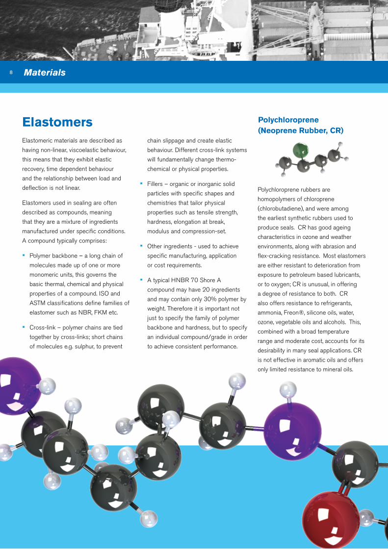
Polychloroprene(neoprene Rubber, CR)
Polychloroprene rubbers are
homopolymers of chloroprene
(chlorobutadiene), and were among
the earliest synthetic rubbers used to
produce seals. CR has good ageing
characteristics in ozone and weather
environments, along with abrasion and
flex-cracking resistance. Most elastomers
are either resistant to deterioration from
exposure to petroleum based lubricants,
or to oxygen; CR is unusual, in offering
a degree of resistance to both. CR
also offers resistance to refrigerants,
ammonia, Freon®, silicone oils, water,
ozone, vegetable oils and alcohols. This,
combined with a broad temperature
range and moderate cost, accounts for its
desirability in many seal applications. CR
is not effective in aromatic oils and offers
only limited resistance to mineral oils.
Elastomeric materials are described as
having non-linear, viscoelastic behaviour,
this means that they exhibit elastic
recovery, time dependent behaviour
and the relationship between load and
deflection is not linear.
Elastomers used in sealing are often
described as compounds, meaning
that they are a mixture of ingredients
manufactured under specific conditions.
A compound typically comprises:
▪ Polymer backbone – a long chain of
molecules made up of one or more
monomeric units, this governs the
basic thermal, chemical and physical
properties of a compound. ISO and
ASTM classifications define families of
elastomer such as NBR, FKM etc.
▪ Cross-link – polymer chains are tied
together by cross-links; short chains
of molecules e.g. sulphur, to prevent
chain slippage and create elastic
behaviour. Different cross-link systems
will fundamentally change thermo-
chemical or physical properties.
▪ Fillers – organic or inorganic solid
particles with specific shapes and
chemistries that tailor physical
properties such as tensile strength,
hardness, elongation at break,
modulus and compression-set.
▪ Other ingredients - used to achieve
specific manufacturing, application
or cost requirements.
▪ A typical HNBR 70 Shore A
compound may have 20 ingredients
and may contain only 30% polymer by
weight. Therefore it is important not
just to specify the family of polymer
backbone and hardness, but to specify
an individual compound/grade in order
to achieve consistent performance.

9
Silicone(vMQ)
Hydrogenated nitrile (HnbR)
nitrile(nbR)
The properties of Hydrogenated Nitrile
Rubber (HNBR) are dependent upon
the acrylonitrile content and the degree
of hydrogenation of the butadiene
copolymer. They have a better oil
and chemical resistance than nitrile
rubber and can withstand much higher
temperatures. HNBR has excellent
resistance to glycol based coolants, hot
water and ozone. Physical properties
(e.g. tensile and tear strength, elongation,
abrasion resistance, compression set,
etc.) are also excellent and compounds
display strong dynamic behaviour at
elevated temperatures.
HNBR can either be cured with sulphur
or peroxide, depending upon which
properties are the most important.
Typical applications include accumulator
bladders, diaphragms, gaskets and
seals. Limitations include poor electrical
properties, poor flame resistance and
attack by aromatic oils..
Silicone elastomers are commonly
used for extreme temperature ranges
(-90°C to +230°C) and offer good low
temperature flexibility. They also offer
resistance to ultra violet radiation (UV),
oxygen and ozone.
Silicone is best suited to non-dynamic
applications, as this elastomer type
possess relatively low tear strength and
abrasion resistance, although higher
strength grades are available. They
are also compliant with engine and
transmission oils, vegetable oils and
some brake fluids.
Nitrile (often referred to as Buna-N)
is the most commonly used elastomer
in the seal industry and is a copolymer
of two monomers; acrylonitrile (ACN)
and butadiene. The properties of
this elastomer are ruled by the ACN
content which is broken down into three
classifications:
High Nitrile: >45% ACN content Medium Nitrile: 30 – 45% ACN content Low Nitrile: <30% ACN content
The higher the ACN content, the
better the elastomers resistance to
hydrocarbon oils. With lower ACN content,
the material offers better flexibility at
low temperatures. Medium nitrile is,
therefore, the most widely specified
due to its good overall balance in most
applications. Typically, nitrile rubber can be
compounded to work over a temperature
range of -35°C to +120°C and is superior
to most other elastomers in regard to
compression set, tear and abrasion
resistance. Nitrile rubbers posses
excellent resistance to oil-based fluids,
vegetable oils, greases, water and air.

10
Types of Flourocarbon Rubber
Fluorocarbon Rubber (FKM, viton®)
FKMs (sometimes known as FPMs in
Europe) are frequently used to resist
extreme temperatures and harsh
chemicals. The strong carbon-fluorine
bonds that make up the polymer
structure provide high thermo-chemical
resistance, giving excellent ageing
characteristics shown by low compression
set at elevated temperatures.
FKMs offer excellent resistance to
mineral oils and greases, aliphatic,
aromatic and some chlorinated
hydrocarbons, fuels, silicone oils and
greases. However FKMs show poor
resistance to bases.
FKMs are available as a copolymer (two
monomers), terpolymer (three monomers)
or as a tetrapolymer (four monomers).
Each type determines both fluorine
content and chemical structure which
in turn significantly impact the chemical
resistance and temperature performance
of the polymer.
More recent innovations include the
development of FKM materials for use in
low temperature applications, where with
a glass transition of -40°C, it is possible
to use FKMs down to -51°C in service.
Specific grades are also available for use
in biofuels, e.g. ethanol or bio-diesel.
Materials
ASTM D1418 Designation
Common Name
Typical Cure systemTypical Fluorine
ContentDescription
Type 1 Viton® A Bisphenol or amine 66% General purpose with excellent mechanical properties
Type 2 Viton® B, F or GFBisphenol, amine or
peroxide66 - 70%
Improved fluid and oil/solvent resistance, including improved fuel resistance. Peroxide cured materials offer improvements
in coolant and water resistance
Type 3 Viton® GLT Peroxide 64 - 67%Improved low temperature resistance but reduced chemical
resistance
Type 4 Aflas® Peroxide 55%Excellent resistance to lubricating oils, corrosion inhibitors and
coolants.
Type 5 Viton® ETP Peroxide 67%Speciality grade, excellent chemical resistance, including
increased resistance to amines and fuel additives.
Ultra-low temp Ultra-low temp Peroxide 66%Speciality polymers are available that further extend the low
temperature performance of FKMs.

11
Types of Perfluoroelastomers
Common FFKM Types
Peroxide 240°C Broad chemical resistance.
Triazinic 327°CHigh temperature, excellent mechanical properties. Reduced
chemical and steam resistance.
Modified Triazinic 275°C Broad chemical resistance, excellent mechanical properties.
Modified Peroxide 325°CHigh temperature resistance, excellent mechanical properties,
reduced amine and base resistance.
Perfluoroelastomers (FFKM)
offer the ultimate thermo-chemical
resistance.
This is demonstrated by the good long-
term, high-temperature, compression-
set resistance. Chemical resistance is
second to none, with good performance
in a broad variety of harsh environments:
performance fuels, MBTE, steam,
solvents, hydrocarbons etc.
Traditionally, FFKM polymers have offered
limited resistance to low temperatures.
New polymer chemistry now offers
FFKM grades capable of sealing at
temperatures down to -40°C.
Although all FFKM polymer backbones
are fully fluorinated, the cross-linking
systems used to join the polymer
chains together differ significantly,
resulting in varied temperature and
chemical resistance.
Perfluoroelastomers (FFKM) have a fully
fluorinated polymer backbone resulting in
a fluorine content >71%. As the material
is free from carbon-hydrogen bonds in
the polymer chain, the FFKM materials

12
Ethylenepropylene Rubbers (EPM, EPdM)
Ethylenepropylene based rubbers
are forms of non-polar synthetic
rubbers. EPM (sometimes also known
as EP) rubber is based on ethylene
and propylene monomers, with no
unsaturation (carbon-carbon double
bonds) present. EPDM is also based on
the same constituent monomers, however
as no unsaturation is present in the
backbone, it is added as a third monomer,
pendent to the main chain. EPDM
materials can be cured with either sulphur
or peroxide; sulphur offers improved
mechanical properties and peroxide
enhanced heat stability. EPM rubber
can only be cured using free-radicals
(peroxide or radiation curing). As the
polymer chains of both EPM and EPDM
have completely saturated hydrocarbon
backbones, excellent ozone resistance
and very good resistance to heat and
oxidation are achieved.
Being non-polar elastomers, EPM and
EPDM offer good performance in polar
fluids such as alcohols, water, steam,
coolants etc., but perform badly in non-
polar fluids such as hydrocarbon oils,
lubricants and greases.
Polyurethane (aU, EU, PU)
Materials
Polyurethane is a polymer formed from a
chain of organic units joined by urethane
links. Polyurethanes are produced by the
addition reaction of a polyisocyanate with
a polyalcohol (polyol) in the presence of a
catalyst and other additives.
Polyurethane demonstrates excellent
resistance to weathering and oxidation.
They resist hydrocarbon fuels and mineral
oils, however some grades degrade
(hydrolyse) in hot water. Polyurethane
also offers some of the best resistance
to abrasion, and are therefore often
specified for use in reciprocating seals.

13
Epichlorohydrin(Co, GCo, ECo, GECo, Hydrin®)
Epichlorohydrin rubber is a synthetic
elastomer which The American Society
for Testing and Materials (ASTM) has
designated as:
▪ CO - Homopolymer of
epichlorohydrin (ECH)
▪ GCO - Copolymer of epichlorohydrin/
allyl glycidyl ether (ECH/AGE)
▪ ECO - Copolymer of epichlorohydrin/
ethylene oxide (ECH/EO)
▪ GECO - Terpolymer of
epichlorohydrin/ethylene oxide/allyl
glycidyl ether (ECH/EO/AGE)
The saturated polymer chain provides
excellent ozone resistance. Levels of
each of the different monomers can be
optimized to improve permeation, fuel and
ozone resistance.
In sealing applications, epichlorohydrin
rubber compounds are noted for
their superior gas impermeability
and physical properties over a wide
temperature range while maintaining
excellent resistance to petroleum oils.
It has a stable cycling capability from
low to high temperature. Resistance
to ozone, oxidation, weathering, and
sunlight are other typical ECO qualities.
Service temperatures are -51°C to
+150°C (-60°F to +300°F).
Epichlorohydrin compounds can
also provide vibration dampening
comparable to natural rubber (NR). This
characteristic makes epichlorohydrin
compounds a good technical candidate
for suspension mounts and impact
absorbers.
acrylic Elastomers (aCM, aEM vamac®)
There are generally two forms of acrylic-
based elastomer available: Polyacrylates
(ACM) and ethylene-acrylates (AEM,
Vamac®).
Polyacrylates offer good resistance to
lubricating oils and high temperatures,
and are commonly used where the
two are found in combination. ACM
elastomers show excellent resistance
to engine oils (semi and fully-synthetic),
petroleum based lubricants, transmission
fluids, aliphatic hydrocarbons, ozone and
ultraviolet radiation.
Ethylene acrylic elastomers (AEM) are
terpolymers of ethylene, acrylic and a
cure-site monomer, supplied by DuPont™
under the tradename of Vamac®. AEM
elastomers exhibit mechanical properties
similar to ACM, although they can
operate over a wider temperature range
than ACM and hydrogenated nitriles
(HNBR).

14
Polytetrafluoroethylene (PTFE)
which offer higher temperature (+315°C)
and deformation resistance. PTFE is
also available with fillers to enhance its
physical characteristics.
Typical fillers include:
▪ Glass fillers for improved deformation
and wear.
▪ Inorganic fillers (e.g. calcium silicate,
wollastonite) are used in a similar
manner to glass fillers, with reduced
abrasiveness.
▪ Carbon-filled for considerable wear
and deformation improvement, and
increased thermal conductivity.
▪ Carbon fibre filled for increased wear
resistance and use against non-
hardened surfaces.
▪ Graphite or molybdenum disulphide
(MoS2) filled to lower the coefficient
of friction.
▪ Bronze filled for excellent wear,
deformation strength, thermal
conductivity (reduced chemical
resistance) .
▪ Polyester filled for improved high
temperature and wear resistance, for
applications where running surfaces
are non-hardened.
▪ Polyphenylenesulphide (PPS) filled
for improved wear extrusion and
deformation resistance.
▪ Polyimide (PI) fillers are used to
increase wear and abrasion resistance,
being polymeric the abrasion of
running surfaces is reduced.
▪ Combinations of some of the above
are also often used to offer optimal
performance in service.
Materials
Materials
PTFE (polytetrafluoroethylene) is a
synthetic, thermoplastic polymer which
offers exceptional chemical resistance
over a wide range of temperatures and
offers extremely low levels of friction.
PTFE lacks elasticity which prevents
its use as an elastomeric-type sealing
ring, however it is commonly used for
anti-extrusion as a back-up ring, and for
non-stick requirements. Owing to its low
friction and excellent chemical resistance,
it is also commonly used for applications
such as bearings, gears, rotary seals etc.
Non-filled (virgin) grades are stable
up to +260°C and are quite flexible
and resistant to breaking under tensile
and compressive stresses. Modified
backbone grades of PTFE are available

15
Polyamide (nylon )
Fabric / Phenolic ResinComposites
Phenolic resins, also known as phenol
formaldehyde resins (PF), are synthetic
thermosetting resins created by the
reaction of phenols with formaldehyde.
These thermosets perform well in
most engineering applications such as:
hydraulic fluids, oils, glycols, phosphate
esters, silicone oils and brake fluids
etc. Phenolic resins demonstrate high
compressive strength, dimensional
stability and abrasion resistance, and are
commonly used in wear-ring applications
as fabric resin composites.
Nylon offers excellent mechanical
properties in combination with good
sheer strength, deformation and wear
resistance. Chemical resistance is
generally broad, with good resistance to
most chemicals, although Nylon can be
susceptible to damage when exposed to
moisture i.e. it is hydroscopic.
Nylon is a generic designation for a family
of synthetic thermoplastic polymers known
as polyamides. Nylons are condensation
copolymers formed by reacting a diamine
and a dicarboxylic acid. Chemical elements
included are carbon, hydrogen, nitrogen,
and oxygen. The numerical suffix specifies
the numbers of carbons donated by the
monomers; the diamine first and the diacid
second.
The most common variant is Nylon 6-6
which refers to the fact that the diamine
and the diacid each donate 6 carbons
to the polymer chain. The levels of
these monomers has an influence on
the chemical resistance as well as the
mechanical properties.

16 Materials
TPEs are advantageous in that they
have elastomeric properties, yet can be
processed using methods more
common in plastics processing (TPEs
can be processed by blow molding,
thermoforming, and heat welding). TPEs
also have advantages with respect to
environmental impact when compared to
traditional thermosetting rubbers: TPEs
have the potential to be recycled since
they can be molded, extruded and re-used
like plastics, but also require less energy
during processing.
The most common types of commercial
TPEs include:
▪ Elastomeric alloys (TPE-v or TPV)
▪ Thermoplastic polyurethanes
▪ Styrenic block copolymers
▪ Polyolefin blends
▪ Thermoplastic copolyester
▪ Thermoplastic polyamides
Thermoplastic Elastomers (TPE)
Thermoplastic elastomers (TPE) are a
range of co-polymers or a physical mix of
polymers (usually a plastic and a rubber).
Those based on mixed polymer systems
consist of polymers with both plastic and
elastic properties. Traditional elastomers
are thermosetting materials with covalent
crosslinks between the polymer chains
(formed during the ‘vulcanisation process’),
but require processing using different
methods to higher-volume thermoplastics,
e.g. higher temperatures, longer
processing times etc.
The major difference between
thermosetting elastomers and TPEs is
the type of crosslink utilized. In TPEs,
the crosslink is a covalent bond; the
crosslinking in TPEs is a weaker dipole,
hydrogen bond, or a covalent bond within
only one of the phases of the material.
Due to the variety of materials available,
each family will offer different chemical
and thermal resistance. Related to
the differences in crosslinking, TPEs
have relatively poor heat resistance
and can show high compression set at
elevated temperatures when compared
to thermosetting elastomers. Therefore,
TPEs are often used in less demanding
applications such as door seals, bumpers,
extruded profiles etc.

17
Common Chemical Compatibilities of Materials
Med
ia
NB
R
HN
BR
CR
AC
M
AE
M
PU
/PE
FKM
(A
)
FKM
(G
F)
VM
Q
EP
DM
TPE
FFK
M
AdBlue 2 2 3 2 2 3 1 1 2 1 1 1
Aliphatic Hydrocarbons 1 1 2 1 2 1 1 1 3 4 4 1
Alkanes 1 1 2 1 2 1 1 1 3 4 4 1
Ammonia 2 2 3 4 4 1 4 4 2 1 1 1
Aromatic Hydrocarbons 1 1 4 2 3 3 1 1 3 4 4 1
Bioethanol 2 2 1 4 3 4 3 1 2 1 1 1
Brake fluid - DOT 3, 4 and 5.1 types 3 3 2 4 4 4 4 3 3 1 1 1
Brake fluid - DOT 5 type 1 1 1 1 1 1 1 1 4 1 1 1
Butanol 2 1 1 4 1 3 1 1 3 1 1 1
Corrosion inhibitors 2 1 2 3 3 3 4 4 3 1 1 1
Crude oil 3 3 3 3 3 3 2 1 3 4 4 1
Diesel fuel 1 1 2 1 1 2 2 1 4 4 4 1
Engine lubricating oils 1 1 2 1 2 1 1 1 3 4 4 1
Ester based hydraulic fluids 4 4 4 4 4 4 3 3 3 4 4 1
Ethanol 2 2 1 4 2 4 1 1 1 1 1 1
Fatty acid methyl ester (FAME) 2 2 2 1 1 2 2 1 3 3 3 1
Glycol-based coolants 2 1 1 4 1 3 3 1 3 1 1 1
Glycol-ether based brake fluids 3 3 2 4 4 4 4 3 3 1 1 1
Heavy fuel oil / bunker fuel 3 3 3 3 3 3 2 1 3 4 4 1
Hydraulic oil 1 1 3 1 1 1 1 1 3 4 4 1
IRM 901 fluid (ASTM Oil #1) 1 1 2 1 1 1 1 1 2 4 4 1
IRM 902 fluid (ASTM Oil #2) 1 1 2 1 1 1 1 1 2 4 4 1
IRM 903 fluid (ASTM Oil #3) 2 2 3 3 3 2 1 1 3 4 4 1
Liquidified natural gas (LNG) 1 2 2 3 4 1 1 1 3 4 4 1
Low sulpur diesel fuel 1 1 2 1 1 2 2 1 4 4 4 1
Lubricating oils (API CC-type) 1 1 2 1 2 1 1 1 3 4 4 1
Lubricating oils (API CD-II-type) 3 1 3 2 3 2 1 1 4 4 4 1
Lubricating oils (API CD-type) 1 1 2 1 2 1 1 1 3 4 4 1
Lubricating oils (API CE-type) 1 1 2 1 2 1 1 1 4 4 4 1
Methanol 2 2 1 4 1 4 2 1 2 1 1 1
Methyltertiarybutylether (MTBE) 4 4 4 4 4 4 4 3 4 3 3 1
Mineral oil 1 1 2 1 2 1 1 1 3 4 4 1
Organophosphate ester 4 4 4 4 4 4 3 3 3 3 3 1
Ozone 2 1 2 1 1 2 1 1 1 1 1 1
Petroleum fuels 2 2 2 2 2 2 2 1 3 4 4 1
Polyalkylene glycol (PAG) 2 1 2 4 2 3 3 1 3 2 2 1
Polyalphaolefin 1 1 2 1 2 1 1 1 3 4 4 1
Polyethylene glycol 2 1 1 4 1 3 3 1 3 1 1 1
Polypropylene glycol 2 1 1 4 1 3 3 1 3 1 1 1
Rapeseed (canola) oil 1 1 3 1 1 1 1 1 4 4 4 1
Refridgerant R134a 1 1 2 1 1 1 4 4 2 1 1 2
Silicone oils 1 1 1 1 1 1 1 1 4 1 1 1
Sythetic oil 1 1 2 1 1 1 1 1 3 4 4 1
Universal Transdraulic fluids 3 4 3 2 3 2 1 1 3 4 4 1
Vegetable oils 1 1 3 1 1 1 1 1 4 4 4 1
Water / coolant <100degC 2 1 2 4 1 2 1 1 1 1 2 1
Water / coolant <150degC 4 3 3 4 3 3 3 1 2 1 4 1
Water / coolant <200degC 4 4 4 4 4 4 4 2 4 3 4 1
Weathering 2 1 1 1 1 1 1 1 1 1 1 1
Material information can also be found on our Chemical Compatibility tool:
http://oring-groove-wizard.eriks.co.uk/chemicalcompatibility.aspx
KEY:1 = Excellent 2 = Good 3 = Poor 4 = not recommended

18 ASTM D2000
american Society for Testing and Materials (aSTM) d-2000 Line call-outs
aSTM d2000-90 M 2 HK _ 7 14 a1-10, b38, C12, EF31, E088, F15, Z_
DEVIATIONS FROM STANDARD TEST PROCEDURES
ADDITIONAL REQUIREMENT SUFFIXES
TENSILE STRENGTH (MPa if M IS PRESENT)
HARDNESS (DUROMETER)
CLASS
TYPE
GRADE NUMBER
UNITS OF MEASURE
Units of measure:If present an “M” denotes that metric units of measure should be used, i.e. MPa for tensile strength, °C for temperature and kN/m
for tear strength.
Grade number1 = Basic Requirements
2 to 6 = Different requirements as detailed in table 6 of ASTM D2000 this specifies minimum basic requirements for tensile
strength, elongation, heat aging, oil immersion and compression set by Classification (Type-class). Appropriate additional
requirements apply to each classification, with the grade determining the allowable results.
Material information can also be found on our Chemical Compatibility tool:
http://oring-groove-wizard.eriks.co.uk/AstmLookup.aspx
The values in this guide have been extracted, with permission, from ASTM D2000-12 Standard Classification System for Rubber Products in Automotive Applications. Users
should reference and confirm results with the originally published version of ASTM D2000-12. The complete standard may be obtained from ASTM, www.astm.org.

19
aSTM d2000-90 M 2 HK _ 7 14 a1-10, b38, C12, EF31, E088, F15, Z_
Material designation
(type and class)
Type of Polymer Most often Used
AA Natural, Reclaim, SBR, Butyl, EPDM, Polyisoprene
AK Polysulfides
BA EPDM, High Temp SBR and Butyl Components
BC Chloroprene
BE Chloroprene
BF NBR
BG NBR, Urethanes
BK NBR
CA EPDM
CE Chlorosulfonated Polythylene (Hypalon®)
CH NBR, Epichlorohydrin
DA EPDM
DF Polyacrylic (Butyl Acrylate type)
DH Polyacrylic
DE CM, CSM
EE AEM
EH ACM
FC Silicones (high Temp)
FE Silicones
FK Fluorosilicones
GE Silicones
HK Fluorosilicones
KK FFKM
With the exception of type/class FC, FE, FK, and GE, all materials are assumed to be black.
Class Max. Swell, %
A No Requirement
B 140
C 120
D 100
E 80
F 60
G 40
H 30
J 20
K 10
Type Test Temp, 0C
A 70
B 100
C 125
D 150
E 175
F 200
G 225
H 250
J 275
K 300
Type
The type classifies materials by temperature resistance. ASTM D2000 limits the
change in mechanical properties following 70 hours of heat ageing to: Tensile strength:
±30%, Hardness: -50% max., Hardness: ±15 points.
The test temperature used defines the Type, designated by a letter.
ClassThe Class classifies materials by their resistance to swelling in ASTM Oil Number 3,
after 70 hours at the temperature defined by the type, up to 150°C, the temperature
limit of the oil. ASTM D2000 limits the maximum allowable volume swell by class.
The allowable volume swell defines the Class, designated by a letter.
Hardness (durometer)The hardness of the material, measured in Shore® A is detailed as a single number which is the specified hardness / 10,
expressed to 0 decimal places. The limit upon variation in hardness is ±5 points.
Tensile strengthMinimum tensile strength is detailed in MPa, or as psi / 100 to 0 decimal places if using imperial (English) units)
20
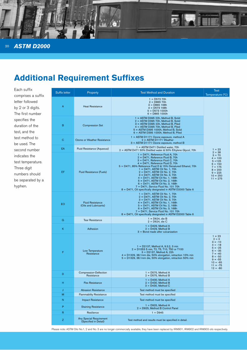
additional Requirement Suffixes
Suffix letter Property Test Method and DurationTest
Temperature (°C)
A Heat Resistance
1 = D573 70h2 = D865 70h
3 = D865 168h4 = D573 168h
5 = D573 1000h6 = D865 1000h
1 = 232 = 383 = 70
4 = 1005 =1256 = 1507 = 1758 = 2009 = 225
10 = 25011 = 275
B Compression Set
1 = ASTM D395 22h, Method B, Solid2 = ASTM D395 70h, Method B, Solid3 = ASTM D395 22h, Method B, Piled4 = ASTM D395 70h, Method B, Piled
5 = ASTM D395 1000h, Method B, Solid6 = ASTM D395 1000h, Method B, Piled
C Ozone or Weather Resistance1 = ASTM D1171 Ozone exposure, method A
2 = ASTM D1171 Weather3 = ASTM D1171 Ozone exposure, method B
EA Fluid Resistance (Aqueous) 1 = ASTM D471 Distilled water, 70h2 = ASTM D471 50% Distilled water & 50% Ethylene Glycol, 70h
EF Fluid Resistance (Fuels)
1 = D471, Reference Fluid A, 70h2 = D471, Reference Fluid B, 70h3 = D471, Reference Fluid C, 70h4 = D471, Reference Fluid D, 70h
5 = D471, 85% Reference Fluid D & 15% Denatured Ethanol, 70h1 = D471, ASTM Oil No. 1, 70h2 = D471, ASTM Oil No. 2, 70h3 = D471, ASTM Oil No. 3, 70h
4 = D471, ASTM Oil No. 1, 168h5 = D471, ASTM Oil No. 2, 168h6 = D471, ASTM Oil No. 3, 168h
7 = D471, Service Fluid No. 101 70h8 = D471, Oil specifically designated in ASTM D2000 Table 6
EO Fluid Resistance (Oils and Lubricants)
1 = D471, ASTM Oil No. 1, 70h2 = D471, ASTM Oil No. 2, 70h3 = D471, ASTM Oil No. 3, 70h
4 = D471, ASTM Oil No. 1, 168h5 = D471, ASTM Oil No. 2, 168h6 = D471, ASTM Oil No. 3, 168h
7 = D471, Service Fluid No. 101 70h8 = D471, Oil specifically designated in ASTM D2000 Table 6
G Tear Resistance 1 = D624, die B2 = D624, die C
K Adhesion1 = D429, Method A2 = D429, Method B
3 = Bond made after vulcanization
F Low Temperature Resistance
1 = D2137, Method A, 9.3.2, 3 min2 = D1053 5 min, T2, T5, T10, T50 or T100
3 = D2137, Method A, 22h4 = D1329, 38.1mm die, 50% elongation, retraction 10% min5 = D1329, 38.1mm die, 50% elongation, retraction 50% min
1 = 232 = 0
3 = -104 = -185 = -256 = -357 = -408 = -509 = -55
10 = -6511 = -7512 = -80
D Compression-Deflection Resistance
1 = D575, Method A2 = D575, Method B
H Flex Resistance1 = D430, Method A2 = D430, Method B3 = D430, Method C
J Abrasion Resistance Test method must be specified
M Flammability Resistance Test method must be specified
N Impact Resistance Test method must be specified
P Staining Resistance 1 = D925, Method A2 = D925, Method B Control Panel
R Resilience 1 = D945
Z Any Special Requirement (Specified in Detail) Test method and results must be specified in detail.
Each suffix
comprises a suffix
letter followed
by 2 or 3 digits.
The first number
specifies the
duration of the
test, and the
test method to
be used. The
second number
indicates the
test temperature.
Three digit
numbers should
be separated by a
hyphen.
ASTM D2000
Please note: ASTM Oils No.1, 2 and No. 3 are no longer commercially available, they have been replaced by IRM901, IRM902 and IRM903 oils respectively.

21
Fuel use in TransportationThe variety of fuels used in transportation
systems is an important factor when
optimum sealing solutions are required.
Petroleum (“petrol”, “gasoline”) and
diesel fuels are the most common
in the automotive market, but recent
developments include bio-based
alternatives. In marine applications
heavy-fuel oils represent a significant
challenge. In each case sealing materials
need to offer: good chemical resistance,
low permeability, and a broad temperature
operating range.
With respect to standard fuels, ECO,
NBR, HNBR and FKMs are all possible
sealing solutions for both petrol and
United States Environmental Protection agency (EPa) Federal Emission Standards
vehicle Classifications:
Light Duty
Vehicles
and Trucks
Clean Fuel Fleet
Clean Vehicle Fuel
National Low Emission Vehicle
Tier 0
Tier 1
Tier 2
Motor Cycles Driving Cycles
Heavy-Duty
Highway
Engines and
Vehicles
Clean Fuel Fleet
Compression Ignition (CI) engines
Spark-ignition (SI engines)
Aircraft
Compression Ignition (CI) Engines
Spark-ignition (SI Engines)
Marine (CI) Engines
Marine (SI) Engines and Vessels
Recreational Engines and Vehicles
SI Engines 19KW and below
The EPA’s Office of Transportation
and Air Quality (OTAQ) determines the
standards controlling mobile source
emission in the US through applicable
Code of Federal Regulations (CFR)
citations.
Standards are grouped by Light Duty,
Heavy Duty, Non-road and Fuel Sulphur
and govern levels of : Non-Methane
Organic Gas (NMOG), Nitrous Oxides
(NOx), Carbon monoxide (CO), Total
hydrocarbon equivalent (THCE), non-
methane hydrocarbon equivalent
(NMHCE), Formaldehyde and Particulate
Matter (PM). Both exhaust and
evaporative emissions are controlled
with the vehicle type and model year
governing the maximum permissible
emissions.
The continuing drive to reduce emissions
demands the use of additives in fuels and
elevated temperatures which both place
increased thermo-chemical demand upon
the seals. ERIKS Sealing Technology are
able to assist in selection of the correct
compounds to resist these challenges,
together with controlling fuel permeability
to achieve evaporative emissions
standards. The permeation of fuels into
and through elastomer components is
challenging due to the variety of fuels
now available in the market place, with
some applications requiring resistance to
more than one type.
diesel applications. However, where
bio-based fuels are used care should
be taken, as not all grades are suitable.
Breakdown products from such fuels
can cause degradation of elastomers,
so specialist materials should be sought,
especially in the case of FKMs.
Heavy fuel oil contains many species
which are problematic for elastomers,
and can require elevated temperatures
to assist the fuel in flowing. Again,
FKMs are common in such systems, with
the family of FFKMs also becoming of
interest due to the long-term chemical
and thermal stability.
For high-performance applications, or
those where numerous different fuels
are encountered (such as fuel delivery
systems), FFKMs are becoming the
material of choice. This is again due to
the broad chemical resistance offered
by FFKMs.
The largest challenge with fuel
systems now comes with increasing
demands for sealing at temperatures
at -40°C and below. Here, standard
materials are reaching their limits. New
technology with FKMs and FFKMs
allows sealing of fuel systems over
a broad range of temperatures, from
-51°C to > +200°C.

22 Production
Production Part approval Process – PPaPTS16949 requires the use of PPAP to provide the evidence that all customer
engineering design records and specification requirements are properly understood
by the supplier. Also showing the process has the potential to produce product
consistently meeting these requirements during an actual production run, at the quoted
production rate.
Typically seals to be used in automotive / transportation applications require the
submission of either a Level 2 or Level 3 PPAP report.
▪ Level 1 - Warrant only (and for designated appearance items, an Appearance
Approval Report) submitted to customer.
▪ Level 2 - Warrant with product samples and limited supporting data submitted to
customer. Typically: initial sample inspection report, drawings, material data-sheets,
part submission warrant.
▪ Level 3 - Warrant with product samples and complete supporting data submitted to
customer. Typically: gauge repeatability and reproducibility, process failure mode
effect analysis (FMEA), control plan, process flow diagram, process capability report,
drawings, material data-sheets, part submission warrant.
Cpk Parts per million defective
1.00 2,700.0
1.10 967.0
1.20 318.0
1.30 96.0
1.40 26.0
1.50 6.8
1.60 1.6
1.70 0.34
1.80 0.06
2.00 0.0018
The use of PPAP drives consistency within the supply chain, minimising enterprise risk.
Process Capability Index – CpkThe Cpk of a process defines how centred the output of the process is between its lower and upper specification limits and how
variable the output is. It is calculated as the ratio of the delta between the actual process mean and the nearest tolerance limit
divided by 3 times the standard deviation.
Although many industrial processes require a minimum process Cpk of 1.33 it is common for automotive applications
to require a Cpk of 1.67.

23Applications
Case Study
Summary
background: A customer was experiencing leakages when using a low-temperature nitrile (NBR)
elastomer in a hydraulic application. The material grade was selected based upon
conformance against a customer specification.
Investigation: The material was re-tested against the full customer specification, with no immediate
problems identified (the material met all requirements). Utilizing Fourier-transform
infrared analysis (FTIR) and thermogravimetric analysis (TGA) it was determined
that the NBR compound in question obtained its low-temperature performance by
being compounded using hydrocarbon-based plasticizers. In service in the hydraulic
application, these plasticizers were being ‘washed out’ with the seal then losing
volume, leading to a reduction in sealing force and leakage. Although the material
met the required specification, it was not actually suitable for the service conditions
over a sustained period.
Solution: Low temperature performance of NBR compounds can be enhanced by the use of
plasticizers and/or selection of a low temperature (low acrylonitrile) polymer. In this
application, by switching from a highly plasticized NBR to a low-ACN content NBR,
the customer could successfully seal the application. Recommendations were made
to the customer as to how their material specification could be updated to prevent
similar future occurrences of the same issue.
ERIKS Sealing Technology are happy to assist customers to select appropriate
ASTM or custom specifications to help them deliver reliable, consistent product.

24 Applications
automotiveautomotive applications post a vast array of needs in under-bonnet, drive-train and ancillary applications.
applications Requirements Seal Profiles Sealing Materials
Steering column Oil / grease resistanceRotary Seals
O-RingsWashers
NBRHNBRFKM
PolyacrylicPTFE
SuspensionOil / grease resistance
Low temperature
Rod sealsRotary sealsPiston rings
Lip sealsFork seals
NBRHNBRPTFE
Braking systemsOil / grease resistance
Low temperature
Cover sealsDiaphragms
O-ringsHydraulic seals
CRNBR
EPDM PTFE
Turbo chargerHeat resistanceLow temperature
wear resistance, low friction O-rings
FKMVMQ
Fuel pump and systemHeat resistanceFuel resistance
Elastomer rotaryPTFE Rotary
O-rings
FKMPTFEFFKM
Water pumpCoolant resistance
Oil Resistance
Elastomer Rotary sealsMechanical seals
O-rings
EPDMNBR
Differential / Gearbox Transmission / Drive shaft
Oil / grease resistanceHeat resistance
Rotary sealsO-rings
NBRHNBRFKMACMPTFE
Radiators
Coolant resistanceLow temperatureSteam resistance
Corrosion inhibitor resistance
Moulded gasketsO-rings
EPDM
Screen wash systemsAntifreeze resistance
Low temperature
O-ringsHydraulic sealsMoulded tube
EPDMNBRPTFE
Air conditioningChemical compatibility
Rapid gas decompression O-ringsEPDMHNBR
Engine head & blockHeat, oil, coolant, wear resistance, low friction
Rotary seals, valve stem O-rings, moulded
components
NBR, FKM, VMQ, ACM, PTFE, FFKM

25
Truck & Trailer, bus & Public Service vehicle
applications Requirements Seal Profiles Sealing Materials
Hub & PinionAbrasion resistance
Dirt exclusionOil / grease resistance
Unitised sealsO-rings
Bespoke rotary seals
NBRHNBRFKMACM
Differential / GearboxTransmissionDrive shaft
Abrasion resistanceDirt exclusion
Oil / grease resistance
O-ringsRotary seals
NBRHNBRFKMACM
EngineHeat resistanceOil resistance
RotaryO-rings
Valve stem sealsLiner seals
FKMPTFEFFKM EPDMVMQACM
Braking SystemsOil compatibilityLow temperatureHigh temperature
Cover seals / BootsDiaphragms / Bellows
O-ringsHydraulic / Pneumatic seals
CRNBR
EPDMVMQ
Buffers & BumpersMechanical strength
Ozone resistanceShock resistance
Rubber mouldings
CRNBRTPE
Suspension systemsOil / grease resistance
Low frictionHigh frequency
Torque arm bushesRotary sealsPiston ringsRod seals
NBRHNBR
26 Applications
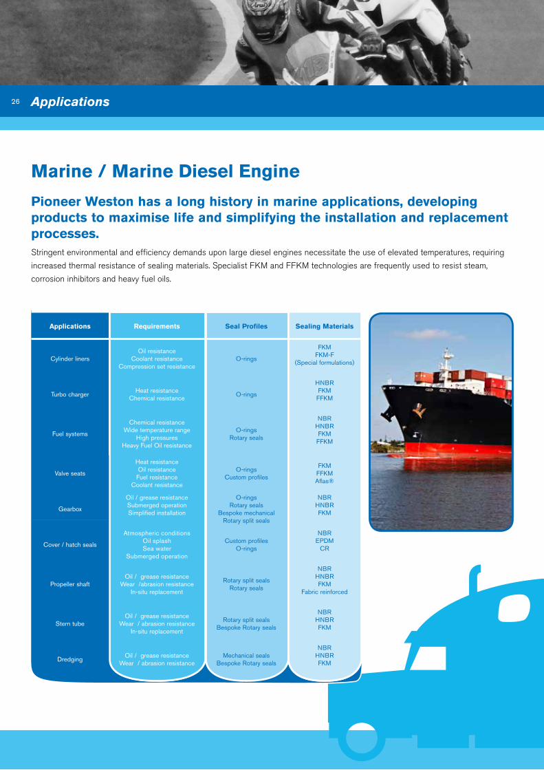
Marine / Marine diesel Engine
Pioneer Weston has a long history in marine applications, developing products to maximise life and simplifying the installation and replacement processes.Stringent environmental and efficiency demands upon large diesel engines necessitate the use of elevated temperatures, requiring
increased thermal resistance of sealing materials. Specialist FKM and FFKM technologies are frequently used to resist steam,
corrosion inhibitors and heavy fuel oils.
applications Requirements Seal Profiles Sealing Materials
Cylinder linersOil resistance
Coolant resistanceCompression set resistance
O-rings
FKMFKM-F
(Special formulations)
Turbo chargerHeat resistance
Chemical resistanceO-rings
HNBRFKM
FFKM
Fuel systems
Chemical resistanceWide temperature range
High pressuresHeavy Fuel Oil resistance
O-ringsRotary seals
NBRHNBRFKM
FFKM
Valve seats
Heat resistanceOil resistance
Fuel resistanceCoolant resistance
O-ringsCustom profiles
FKMFFKMAflas®
Gearbox
Oil / grease resistanceSubmerged operation Simplified installation
O-ringsRotary seals
Bespoke mechanicalRotary split seals
NBRHNBRFKM
Cover / hatch seals
Atmospheric conditionsOil splashSea water
Submerged operation
Custom profilesO-rings
NBREPDM
CR
Propeller shaftOil / grease resistance
Wear /abrasion resistanceIn-situ replacement
Rotary split sealsRotary seals
NBRHNBRFKM
Fabric reinforced
Stern tubeOil / grease resistance
Wear / abrasion resistanceIn-situ replacement
Rotary split sealsBespoke Rotary seals
NBRHNBRFKM
DredgingOil / grease resistance
Wear / abrasion resistanceMechanical seals
Bespoke Rotary seals
NBRHNBRFKM

27
Rail
Utilities
applications Requirements Seal Profiles Sealing Materials
Screw compressorsHigh speed
High temperatureLow friction
PTFE Lip sealsO-rings
Moulded gaskets Poppet valve seats
PTFEFKMVMQ
Brake actuation (Pneumatic)
Lubricant compatibilityLow temperature
Cover sealsDiaphragms
O-ringsMoulded gaskets
U-cupsWipers
CRNBRAU
Valves / Manifolds(Pneumatic)
Lubricant compatibilityLow temperature
O-ringsPneumatic seals
Poppet valve seals
PUNBR
HNBRPTFE
Axle / Bogie
Grease compatibilityAbrasion resistance
Low frictionDirt / water ingress resistance
Bespoke rotary sealsWear sleeves
Poppet valve seats
NBRHNBR
Engine head & blockHeat, oil, coolantWear resistance
Low friction
Rotary sealsValve stem O-rings
Moulded components
NBRFKMVMQACMPTFEFFKM
applications Requirements Seal Profiles Sealing Materials
Screw compressorsHigh speed
High temperatureLow friction
PTFE Lip sealsO-rings
PTFENBR
HNBRFKM
Hydraulic actuation
Wear resistanceDirt exclusion
Oil / Grease resistanceTight leakage control
Low temperatureHigh pressures
O-ringsU-cups
Cap sealsBearingsX-rings
ExcludersWipers
NBRFKMPTFEPU
Fabric reinforced
Pneumatic actuation
Wear resistanceDirt exclusion
Oil / Grease resistanceTight leakage control
Low temperature
Cap sealsO-ringsU-cupsX-rings
ExcludersWipers
NBRFKMPTFEPU
Fabric reinforcedThermoplastics

28
Product overview One of the most frequently used types of seal is the rotary lip seal, generally used for
sealing lubricating oil or grease in rotary shaft applications. This is achieved by:
▪ Providing static sealing between the outer diameter of the seal and its housing.
▪ Sealing between the shaft and the main sealing lip when either static or dynamic.
The radial load exerted by the sealing lip must be sufficient to retain the oil or
grease, but not so high that excessive friction or wear occurs.
The principal of this can be affected by the following basic parameters and must
always be taken into consideration when selecting the correct profile and material to
enable the optimum performance.
▪ Shaft rotational speed and direction
▪ Operating temperature
▪ Application hardware details
▪ Medium being sealed both internally and externally
▪ Pressure seen within sealed unit
The Pioneer Weston range of rotary lip seals, offered through the
ERIKS group, comply with a range of standards including
DIN 3760/3761 and ISO 6194. Non-standard designs and
materials are available on request.
Elastomeric Rotary Lip Seals
Products

29
Profile Profile Features Profile Advantages Applications
R4 – Ground metal outer diameter
– Spring-loaded primary seal lip
– Press fit metal OD for precise location in housing
– Used in a wide and varied number of applications
– Transmission
– Gearbox
– Axles
R6 – Ground metal outer diameter
– Spring-loaded primary seal lip
– Additional dust lip
– Press fit metal OD for precise location in housing
– Used in a wide and varied number of applications
– The addition of a dust lip offers protection against low to medium dust and dirt ingress
– Similar to R4 but within environments where contaminants are present
R21 – Rubber covered outer diameter
– Spring-loaded primary seal lip
– Rubber OD sealing allows use in housings of increased roughness or with minor surface defects
– Used in a wide and varied number of applications
– The addition of a dust lip for R23 style offers protection against low to medium dust and dirt ingress
– Can accommodate housing materials with high thermal expansion
– Transmission
– Gearbox
– Axles
– Crankshafts
R23 – Rubber covered outer diameter
– Spring-loaded primary seal lip
– Additional dust lip
– Rubber OD sealing allows use in housings of increased roughness or with minor surface defects
– Used in a wide and varied number of applications
– The addition of a dust lip offers protection against low to medium dust and dirt ingress
– Can accommodate housing materials with high thermal expansion
– Similar to R21 but within environments where contaminants are present
R1 – Ground metal outer diameter
– Spring loaded primary seal lip
– Additional reinforcing metal insert
– Press fit metal OD for precise location in housing
– Metal insert gives seal more rigidity specifically for larger sizes
– Can accommodate greater installation errors
– Similar to R4
R5 – Ground metal outer diameter
– Two spring loaded seal lips incorporated in to one design
– Press fit metal OD for precise location in housing
– Seal for separation of two media or where liquid or viscous contaminant is present
– Axles
– Power take-off units
R12 – Ground metal outer diameter
– Primary sealing lip without spring
– Good solution for grease applications
– Can be used as a second seal against low to medium dirt and dust ingress
– Press fit metal OD for precise location in housing
– Similar to R4 but in grease filled applications
R26 – Rubber covered outer diameter
– Primary sealing lip without spring
– Good solution for grease applications
– Can be used as a second seal against low to medium dirt and dust ingress
– Rubber OD sealing allows use in housings of increased roughness or with minor surface defects
– Similar to R21 but in grease filled applications
R14 – Rubber covered outer diameter
– Spring-loaded shorter primary seal lip
– Additional dust lip
– For use in pressure rated applications up to 8 bar dependent on rpm
– Rubber OD sealing allows use in housings of increased roughness or with minor surface defects
– The addition of a dust lip offers protection against low to medium dust and dirt ingress from application environment
– Can accommodate housing materials with high thermal expansion
– Hydraulic pumps
– Hydraulic motors
Elastomeric Rotary Lip Styles

30
W
iMPERiAL DESiGNAToR
Imperial (English)
300 200 37 R4 F1 / 29
MATERiAL DESiGNAToRF1
RoTARY PRoFiLE R4
WiDTH† 0.37”
SHAFT DiAMETER†
2.00”
HoUSiNG DiAMETER† 3.00”
-
†Dimension rounded down to 2 decimal places then multiplied by 100
SPECiAL FEATURE iF APPLiCABLE
Standard Rotary Lip Seal Elastomeric Compound Reference
Products
Polmer TypeCompound Reference
ColourHardnes (iRHD)
Temperature Range Select for..Material
Designator
Nitrile rubber (NBR) N-70-194 Black 70 -35 to +110°C General purpose
Fluorocarbon (FKM, A-type)
V-75-27 Black 75 -20 to +200°C
High temperature performance; high speed applications
F1
V-85-195 Black 85 -20 to +200°C F2
V-75-50 Brown 75 -20 to +200°C F3
V-80-271 Black 80 -51 to +200°C Specialist ultra-low temperature FKM F4
V-80-88 Black 80 -15 to +200°CSpecialist FKM terpolymer developed for use
with bio-fuelsF5
Silicone (VMQ) S-80-78 Red 80 -55 to +230°CHigh and very low temperature; high
eccentricityS1
Polyacrylate (ACM) A-70-196 Black 70 -30 to +175°CHigh and low temperature capabilities; good
compatibility with engine oilsA1
Hydrogenated nitrile (HNBR)
H-80-40 Black 80 -40 to +180°C Abrasion resistance; high temperatures H1
Other materials are available on request

31
R
METRiC DESiGNAToR
Metric
20 30 7 R21 F1 / 50 / C
MATERiALF1
PRoFiLE R21
WiDTH 7mm
HoUSiNG DiAMETER 30mm
SHAFT DiAMETER 20mm
-SPECiAL FEATURE iF APPLiCABLE
Feature Function Selection Designator
Ribbed outer diameterHelps to reduce press in force and improves static sealing on outer
diameter. This function is primarily used for aftermarket requirements and is available only on seals with elastomeric outer diameters.
As per ag-con 50
Hydrodynamic aidHelps as a pumping aid to improve functionality of the seal by
transferring fluid away from the lip at high speeds to give a positive impact on the life of the seal.
ClockwiseAnti-clockwiseBi-directional
CAB
Stainless steel spring Rust and acid resistant spring As per ag-con 29
Sealant paintOnly available on metal cased seals, this sealant paint helps to seal
against any housing imperfections.RED
BLUE23
Special Feature designator
If multiple special features are required, these should be expressed using multiple suffixes separated by a “/” sequenced as per
the above table. Examples below:
A metric sized fluorocarbon R21 with a ribbed outer diameter and clockwise hydrodynamic aid, would be as follows:
R20X30X7R21-F1/50/C
An imperial sized HNBR R23 with an anti-clockwise hydrodynamic aid and stainless steel spring would be as follows:
W30020037R23-H1/A/29
XX

32
PTFE Rotary Lip Seals
Products
Product overview Pioneer Weston’s high speed PTFE seal range was first introduced during the 1970s
to offer a superior performance to existing rubber seals. This is characterised by the
following advantages across this range:
▪ Low friction
▪ Aggressive media resistance
▪ Temperature extremes -100 °C to +250 °C
▪ Shaft surface speeds up to 30 metres/sec.
▪ Dry running qualities – reducing breakout friction and stiction
▪ Low lip wear ensuring prolonged service life
▪ Extended shelf life – unaffected by ultraviolet & oxidation
▪ Reduced shaft grooving
Performance can be optimised through the selection of specific
PTFE grades, see page 14 for examples of filler packages.
The Pioneer Weston range of PTFE lip seals, offered through the ERIKS group,
retro-fit into hardware dimensions as defined in standards including DIN 3760/3761
and ISO 6194. Non-standard designs and materials are available on request.

33
Profile Profile Features Profile Advantages Applications
R81 – Ground metal outer diameter with OD sealant paint
– Primary PTFE sealing element with hydrodynamic aid
– Elastomeric gasket
– Press fit metal OD for precise location in housing
– OD sealant paint can help to seal slight housing imperfections
– Directional hydrodynamic sealing aid to provide pumping action to increase sealing ability
– Fuel pumps
– Compressors
R88 – Ground metal outer diameter with OD sealant paint
– Primary PTFE sealing element with hydrodynamic aid
– Additional PTFE wiper lip for R88 style
– Elastomeric gasket
– Press fit metal OD for precise location in housing
– The addition of wiper lip offers protection against low to medium dust and dirt ingress from application environment
– OD sealant paint can help to seal slight housing imperfections
– Directional hydrodynamic sealing aid to provide pumping action to increase sealing ability
– Diesel engine crankshafts
– Transmissions
R82 – Ribbed elastomeric covered outer diameter
– Primary PTFE sealing element with hydrodynamic aid bonded to inner shell
– Elastomer dust lip
– Ribbed elastomer OD sealing allows use in housings of increased roughness or with minor surface defects.
– The addition of a dust lip offers protection against low to medium dust and dirt ingress from application environment
– Directional hydrodynamic sealing aid to provide pumping action to increase sealing ability
– Diesel engine crankshafts
– Gearboxes
PTFE Rotary Lip Styles

34
W
SHAFT DiAMETER† 5.00”
Imperial (English)
600 500 M / / /S2 E2 a / 2
PTFE DESiGNAToRE2
ELASToMER DESiGNAToR S2
SHELL MATERiAL DESiGNAToR M
PRoFiLE R81
WiDTH† 0.50”
SPECiAL FEATURE iF APPLiCABLE
Elastomer Compounds
iMPERiAL DESiGNAToR
HoUSiNG DiAMETER† 6.00”
50 R81 -
Metal Shell Material Desiginator
Mild Steel M
Stainless Steel S
Aluminium AL
†Dimension rounded down to 2 decimal places then multiplied by 100
Shell Materials
Products
Polymer FamilyCompound Reference
ColourHardness
(iRHD)Temperature Range Select for..
Elastomer Designator
Fluorocarbon (FKM, A-type)
V-75-198 Black 75 -20 to +200°CHigh temperature performance; high speed
applicationsF4
Silicone (VMQ) S-70-197 Red 70 -55 to +230°CHigh and very low temperature; high
eccentricityS2
Polyacrylate (ACM)A-70-196 Black 70 -30 to +175°C
High and low temperature capabilities; good compatibility with engine oils
A1

35
Feature Function Selection Designator
Hydrodynamic aidHelps as a pump aid to improve functionality of the seal by transferring fluid away from the lip at high speeds to
give a positive impact on the life of the seal
Clockwise C
Anti-clockwise A
OD sealant paint Only available on metal cased seals, this sealant paint helps to seal against any housing imperfections
RED 2
BLUE 3
Special Features designator
If multiple special features are required then these should be expressed using multiple suffixes separated by a “/ ” sequenced as per the above table e.g. An R81 profile with a clockwise hydrodynamic aid and red sealant paint would be as follows; W60050050R81-M/S2/E1/C/2
Material Composition
Compound Reference
ColourCoefficient of Friction
Temperature Range Select for..PTFE
Designator
Glass and MoS2 reinforced PTFE
PF-200 Grey 0.06 / 0.10 -160 to +290°C Low wear, high life, reduced friction E1
Graphite reinforced PTFE
PF-201 Grey / Black 0.06 / 0.10 -200 to +250°C Soft shafts, reduced friction E2
PTFE Grades
R
HoUSiNG DiAMETER 100mm
Metric
80 100 M S2 E1 a / 2
PTFE DESiGNAToRE1
ELASToMER DESiGNAToR S2
SHELL MATERiAL DESiGNAToR M
PRoFiLE R82
WiDTH 10mm
SPECiAL FEATURE iF APPLiCABLE
METRiC DESiGNAToR
SHAFT DiAMETER 80mm
X10X R82 - / / /
Other grades are available on request.
36
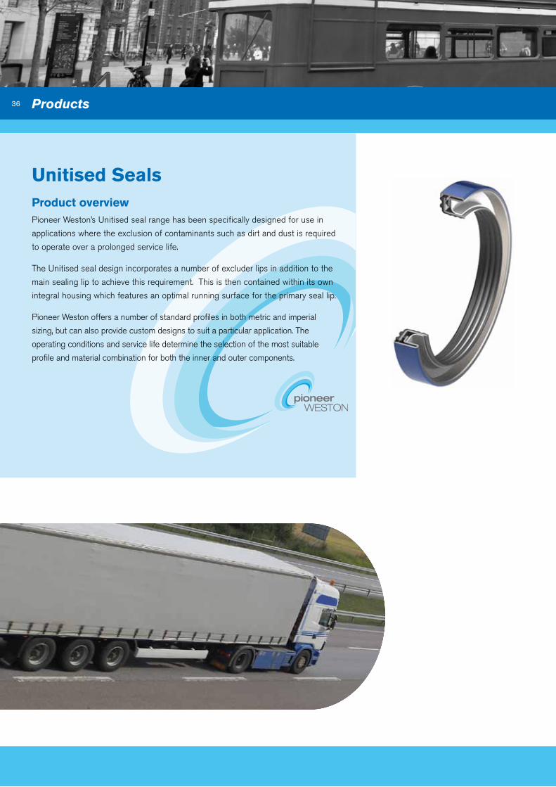
Unitised Seals
Products
Product overview Pioneer Weston’s Unitised seal range has been specifically designed for use in
applications where the exclusion of contaminants such as dirt and dust is required
to operate over a prolonged service life.
The Unitised seal design incorporates a number of excluder lips in addition to the
main sealing lip to achieve this requirement. This is then contained within its own
integral housing which features an optimal running surface for the primary seal lip.
Pioneer Weston offers a number of standard profiles in both metric and imperial
sizing, but can also provide custom designs to suit a particular application. The
operating conditions and service life determine the selection of the most suitable
profile and material combination for both the inner and outer components.
Unitised Seals

37
Seal Profile Profile Features Profile Advantages Applications
R52 – Two piece construction
– Protected radial spring-loaded primary seal lip with hydrodynamic aid
– Excluder lips
– Ribbed elastomer inner diameter
– Ground metal outer diameter with sealant paint
– Integral running surface
– Press fit metal OD for precise location in housing, addition of bore sealant paint helps to fill small imperfections in housing.
– Ribbed elastomer ID gives effective static sealing on shaft surface as well as aiding installation.
– Excluder lips offer contamination protection from the environment.
– Integral running surface means no shaft grooving and calls for no special shaft preparation.
– A bi-directional hydrodynamic aid helps as a pumping aid to improve functionality of the seal, by transferring fluid away from the lip at high speeds to give a positive impact on the life of the seal.
– Primary lip is protected against installation and contamination damage, located remotely from the entry point of any dirt ingress.
– Large wheel hubs
– Pinions
– Prop shafts
R53 – Two piece construction
– Protected radial spring-loaded primary seal lip
– Excluder lips
– Ribbed elastomer inner and outer diameter
– Integral running surface
– Elastomer OD sealing allows use in housings of increased roughness or with minor surface defects as well as aiding installation.
– Ribbed elastomer ID and OD gives effective static sealing on shaft surface as well as aiding installation.
– Excluder lips offer contamination protection from the environment.
– Integral running surface means no shaft grooving and calls for no special shaft preparation.
– Centrifugal lip configuration to allow a constant lip load to be maintained at varying speeds.
– A bi-directional hydrodynamic aid helps as a pumping aid to improve functionality of the seal, by transferring fluid away from the lip at high speeds to give a positive impact on the life of the seal.
– Primary lip is protected against installation and contamination damage, located remotely from the entry point of any dirt ingress.
– Large wheel hubs
– Pinions
– Prop shafts
R57 – Robust 3 piece construction
– Protected radial spring-loaded primary seal lip with hydrodynamic aid
– Excluder lip with fixed interference
– Ribbed elastomer inner and outer diameter
– Integral running surface
– Increased depth of seal
– Elastomer OD sealing allows use in housings of increased roughness or with minor surface defects as well as aiding installation.
– Ribbed elastomer ID and OD gives effective static sealing on shaft surface as well as aiding installation.
– Excluder lip offer contamination protection from the environment.
– Integral running surface means no shaft grooving and calls for no special shaft preparation.
– Centrifugal lip configuration to allow a constant lip load to be maintained at varying speeds.
– A bi-directional hydrodynamic aid helps as a pumping aid to improve functionality of the seal, by transferring fluid away from the lip at high speeds to give a positive impact on the life of the seal.
– Fixed interference of wiper lip ensures wiper contact at all times.
– Suitable for deep bore applications common on American hub units.
– Environmentally exposed surfaces rubber covered.
– Primary lip is protected against installation and contamination damage, located remotely from the entry point of any dirt ingress.
– Large wheel hubs
R59 – Two piece construction
– Ground metal outer diameter with sealant paint
– Ribbed elastomer inner diameter
– PTFE primary lip
– Excluder lips
– Integral running surface
– Press fit metal OD for precise location in housing, addition of bore sealant paint helps to fill small imperfections in housing.
– Ribbed elastomer ID gives effective static sealing on shaft surface as well as aiding installation.
– PTFE primary lip allows for use at high speeds and helps reduce friction and increase life.
– Excluder lips offer contamination protection from the environment.
– Integral running surface means no shaft grooving and calls for no special shaft preparation.
– Optional hydrodynamic aid helps as a pumping aid to improve functionality of the seal, by transferring fluid away from the lip at high speeds to give a positive impact on the life of the seal.
– Primary lip is protected against installation and contamination damage, located remotely from the entry point of any dirt ingress.
– Diesel engine crankshaft
– Differential
– Transmission
– Pinions
– Small wheel hubs
Unitised Seal Styles
38
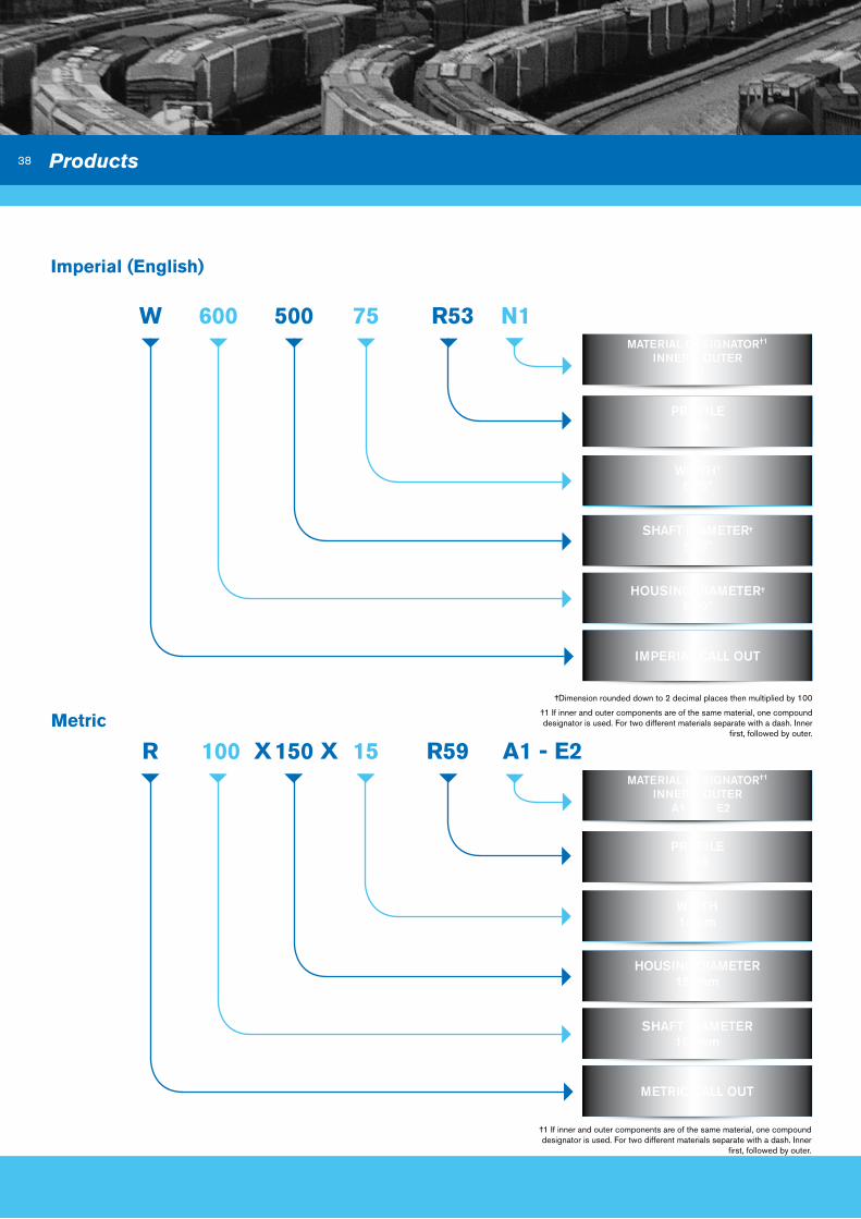
W
iMPERiAL CALL oUT
Imperial (English)
600 500 75 R53 n1
PRoFiLE R53
WiDTH†
0.75”
SHAFT DiAMETER†
5.00”
HoUSiNG DiAMETER†
6.00”
R
METRiC CALL oUT
Metric
100 X 150 X 15 R59 a1 - E2
PRoFiLER59
WiDTH15mm
HoUSiNG DiAMETER150mm
SHAFT DiAMETER 100mm
†Dimension rounded down to 2 decimal places then multiplied by 100
†1 If inner and outer components are of the same material, one compound designator is used. For two different materials separate with a dash. Inner
first, followed by outer.
†1 If inner and outer components are of the same material, one compound designator is used. For two different materials separate with a dash. Inner
first, followed by outer.
MATERiAL DESiGNAToR†1
iNNER – oUTER N1
MATERiAL DESiGNAToR†1
iNNER – oUTER A1 - E2
Products
39
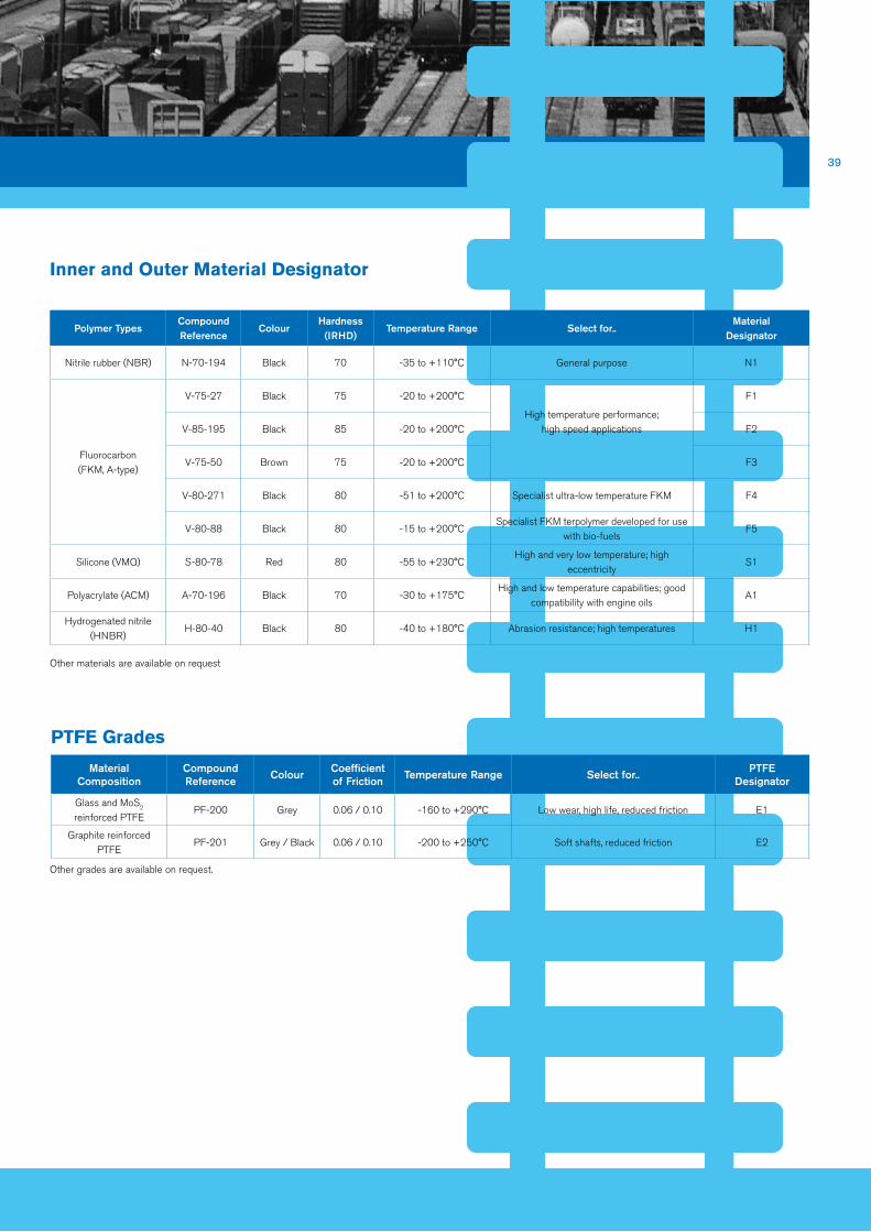
Inner and outer Material designator
Other materials are available on request
Polymer TypesCompound Reference
ColourHardness
(iRHD)Temperature Range Select for..
Material Designator
Nitrile rubber (NBR) N-70-194 Black 70 -35 to +110°C General purpose N1
Fluorocarbon (FKM, A-type)
V-75-27 Black 75 -20 to +200°C
High temperature performance; high speed applications
F1
V-85-195 Black 85 -20 to +200°C F2
V-75-50 Brown 75 -20 to +200°C F3
V-80-271 Black 80 -51 to +200°C Specialist ultra-low temperature FKM F4
V-80-88 Black 80 -15 to +200°CSpecialist FKM terpolymer developed for use
with bio-fuelsF5
Silicone (VMQ) S-80-78 Red 80 -55 to +230°CHigh and very low temperature; high
eccentricityS1
Polyacrylate (ACM) A-70-196 Black 70 -30 to +175°CHigh and low temperature capabilities; good
compatibility with engine oilsA1
Hydrogenated nitrile (HNBR)
H-80-40 Black 80 -40 to +180°C Abrasion resistance; high temperatures H1
Material Composition
Compound Reference
ColourCoefficient of Friction
Temperature Range Select for..PTFE
Designator
Glass and MoS2 reinforced PTFE
PF-200 Grey 0.06 / 0.10 -160 to +290°C Low wear, high life, reduced friction E1
Graphite reinforced PTFE
PF-201 Grey / Black 0.06 / 0.10 -200 to +250°C Soft shafts, reduced friction E2
PTFE Grades
Other grades are available on request.

40
Technical and Installation Information
Housings Materials Most engineering materials can accommodate standard rotary lip seals. All steels and cast iron are suitable providing they are
machined in accordance with the standards given, and there are no surface imperfections sufficient to provide a leak path. High
thermal expansion materials such as light alloys and plastics are best catered for by rubber covered seals of the R21 and R23
types.
Surface Roughness, dimensions and Tolerances
Parameter Seals with Metal outer Diameter Seals with Rubber outer Diameter
Surface Roughness (Ra) 0.2 - 0.8 µm 1.6 - 6.3 µm
Tolerance (ISO 286) H8 H8
Housing Diameter Length of Chamfer Housing Bore Radius
Up to and Including 100mm(4.000")
0.70 to 1.00mm0.028" to 0.040"
0.75mm max 0.030" max
Over 100mm(4.000")
1.20 to 1.50mm0.047" to 0.059"
1.00mm max0.040" max
Products
41
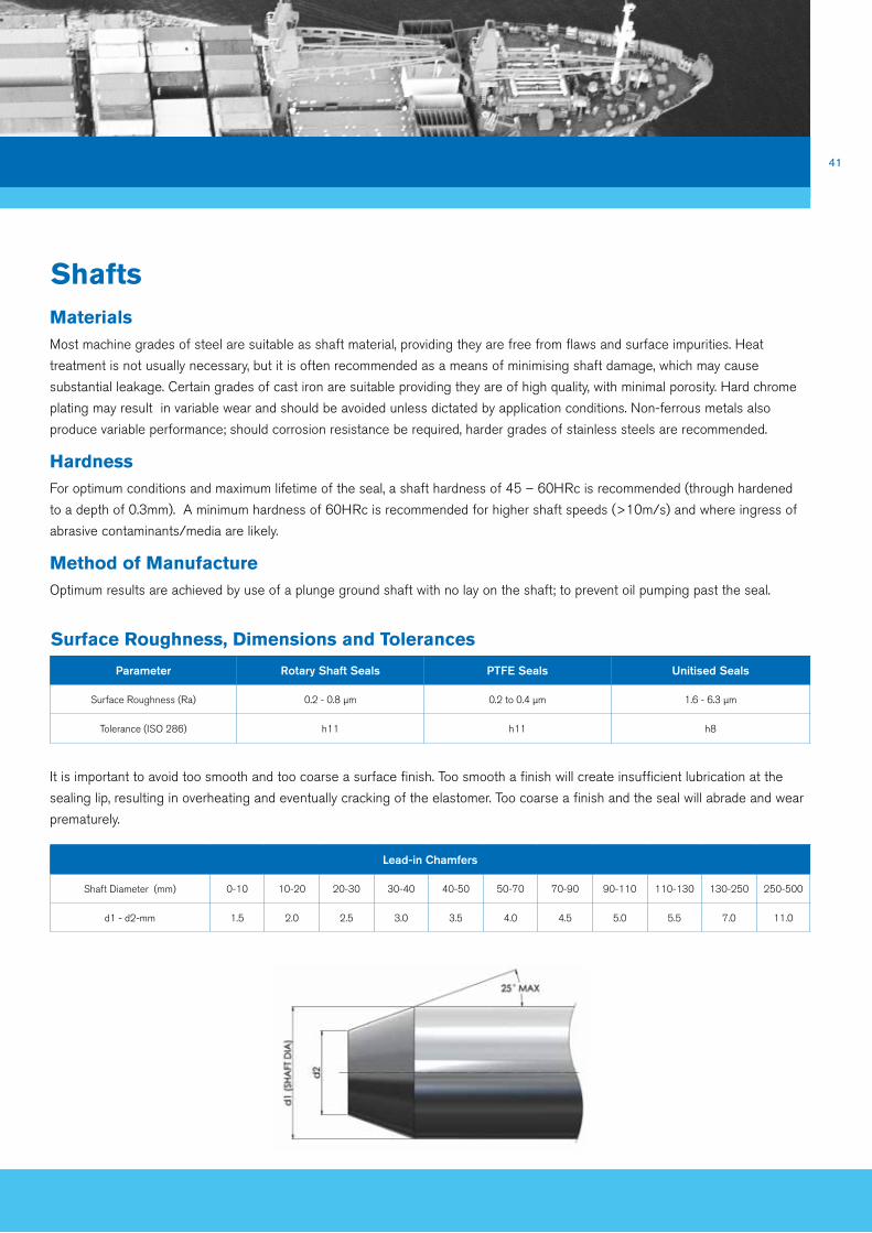
Shafts
Parameter Rotary Shaft Seals PTFE Seals Unitised Seals
Surface Roughness (Ra) 0.2 - 0.8 µm 0.2 to 0.4 µm 1.6 - 6.3 µm
Tolerance (ISO 286) h11 h11 h8
Surface Roughness, dimensions and Tolerances
Lead-in Chamfers
Shaft Diameter (mm) 0-10 10-20 20-30 30-40 40-50 50-70 70-90 90-110 110-130 130-250 250-500
d1 - d2-mm 1.5 2.0 2.5 3.0 3.5 4.0 4.5 5.0 5.5 7.0 11.0
MaterialsMost machine grades of steel are suitable as shaft material, providing they are free from flaws and surface impurities. Heat
treatment is not usually necessary, but it is often recommended as a means of minimising shaft damage, which may cause
substantial leakage. Certain grades of cast iron are suitable providing they are of high quality, with minimal porosity. Hard chrome
plating may result in variable wear and should be avoided unless dictated by application conditions. Non-ferrous metals also
produce variable performance; should corrosion resistance be required, harder grades of stainless steels are recommended.
HardnessFor optimum conditions and maximum lifetime of the seal, a shaft hardness of 45 – 60HRc is recommended (through hardened
to a depth of 0.3mm). A minimum hardness of 60HRc is recommended for higher shaft speeds (>10m/s) and where ingress of
abrasive contaminants/media are likely.
Method of Manufacture Optimum results are achieved by use of a plunge ground shaft with no lay on the shaft; to prevent oil pumping past the seal.
It is important to avoid too smooth and too coarse a surface finish. Too smooth a finish will create insufficient lubrication at the
sealing lip, resulting in overheating and eventually cracking of the elastomer. Too coarse a finish and the seal will abrade and wear
prematurely.

42
Shaft Misalignment
0.00
0.05
0.10
0.15
0.20
0.25
0.30
0.35
0.40
0 50 100 150 200 250 300
Shaft Diameter (mm)
Sha
ft E
ccen
tric
ity (m
m)
0.00
0.05
0.10
0.15
0.20
0.25
0.30
0.35
0.40
0 1000 2000 3000 4000 5000 6000 7000 8000
Shaft Velocity (rpm)
Sha
ft R
un-o
ut (m
m)
VMQ
NBR, ACM, FKM
0.00
0.20
0.30
0.40
0.50
0.60
1000 2000 3000 4000 5000 6000
Revolutions per minute (rpm)
Loss
of P
ower
(hp)
Ø80
Shaft D
iameter (m
m)
Ø70
Ø60
Ø50Ø40
Ø30
Ø20Ø10
0.10
0
4000
8000
12000
16000
20000
0 20 40 60 80 100 120 140 160 180 200
Shaft Diameter (mm)
Per
mis
sabl
e sp
eed
(rpm
)
0 20 40 60 80 100 120 140 160 180 200 220
0,40
0,30
0,20
0,10
0
shaf
t exc
entr
icity
in m
m
shaft diameter till 500 mm
ACM
VMQ, FKM
NBR
0.00
0.05
0.10
0.15
0.20
0.25
0.30
0.35
0.40
0 50 100 150 200 250 300
Shaft Diameter (mm)
Sha
ft E
ccen
tric
ity (m
m)
0.00
0.05
0.10
0.15
0.20
0.25
0.30
0.35
0.40
0 1000 2000 3000 4000 5000 6000 7000 8000
Shaft Velocity (rpm)
Sha
ft R
un-o
ut (m
m)
VMQ
NBR, ACM, FKM
0.00
0.20
0.30
0.40
0.50
0.60
1000 2000 3000 4000 5000 6000
Revolutions per minute (rpm)
Loss
of P
ower
(hp)
Ø80
Shaft D
iameter (m
m)
Ø70
Ø60
Ø50Ø40
Ø30
Ø20Ø10
0.10
0
4000
8000
12000
16000
20000
0 20 40 60 80 100 120 140 160 180 200
Shaft Diameter (mm)
Per
mis
sabl
e sp
eed
(rpm
)
0 20 40 60 80 100 120 140 160 180 200 220
0,40
0,30
0,20
0,10
0
shaf
t exc
entr
icity
in m
m
shaft diameter till 500 mm
ACM
VMQ, FKM
NBR
Eccentricity between the centre line of the shaft and the centre line of the housing bore should be kept to a
minimum, if there is a large deviation between the two, a unilateral load will be applied to the sealing edge,
thus creating heavier wear on one side of the seal. This will in time affect the performance and the life of the
seal. For permissible values see graph.
Shaft Run-out (T.I.R.)Shaft run-out is to be avoided as much as possible, at higher shaft surface speeds it is increasingly difficult
(due to its inertia) for the sealing lip to follow the shaft if there is any run-out present. If the lip cannot follow
the shaft, the edge will lift from the shaft allowing a leak path through the inside diameter of the seal. This can
be kept to a minimum by locating the seal in close proximity to the bearing. Permissible run-out values are
shown below.
Products
Run
-out
Sha
ft of
fset
Sha
ft R
un-o
ut (m
m)
Sha
ft E
ccen
tric
ity (m
m)
Shaft Velocity (rpm)
Shaft Diameter (mm)
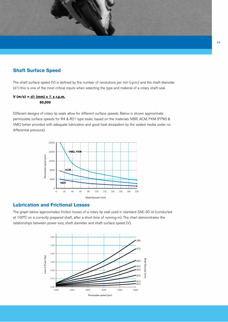
43
Lubrication and Frictional LossesThe graph below approximates friction losses of a rotary lip seal used in standard SAE-30 oil (conducted
at 100°C on a correctly prepared shaft, after a short time of running-in). The chart demonstrates the
relationships between power loss, shaft diameter and shaft surface speed (V).
0.00
0.05
0.10
0.15
0.20
0.25
0.30
0.35
0.40
0 50 100 150 200 250 300
Shaft Diameter (mm)
Sha
ft E
ccen
tric
ity (m
m)
0.00
0.05
0.10
0.15
0.20
0.25
0.30
0.35
0.40
0 1000 2000 3000 4000 5000 6000 7000 8000
Shaft Velocity (rpm)
Sha
ft R
un-o
ut (m
m)
VMQ
NBR, ACM, FKM
0.00
0.20
0.30
0.40
0.50
0.60
1000 2000 3000 4000 5000 6000
Revolutions per minute (rpm)
Loss
of P
ower
(hp)
Ø80
Shaft D
iameter (m
m)
Ø70
Ø60
Ø50Ø40
Ø30
Ø20Ø10
0.10
0
4000
8000
12000
16000
20000
0 20 40 60 80 100 120 140 160 180 200
Shaft Diameter (mm)
Per
mis
sabl
e sp
eed
(rpm
)
0 20 40 60 80 100 120 140 160 180 200 220
0,40
0,30
0,20
0,10
0
shaf
t exc
entr
icity
in m
m
shaft diameter till 500 mm
ACM
VMQ, FKM
NBR
0.00
0.05
0.10
0.15
0.20
0.25
0.30
0.35
0.40
0 50 100 150 200 250 300
Shaft Diameter (mm)
Sha
ft E
ccen
tric
ity (m
m)
0.00
0.05
0.10
0.15
0.20
0.25
0.30
0.35
0.40
0 1000 2000 3000 4000 5000 6000 7000 8000
Shaft Velocity (rpm)
Sha
ft R
un-o
ut (m
m)
VMQ
NBR, ACM, FKM
0.00
0.20
0.30
0.40
0.50
0.60
1000 2000 3000 4000 5000 6000
Revolutions per minute (rpm)
Loss
of P
ower
(hp)
Ø80
Shaft D
iameter (m
m)
Ø70
Ø60
Ø50Ø40
Ø30
Ø20Ø10
0.10
0
4000
8000
12000
16000
20000
0 20 40 60 80 100 120 140 160 180 200
Shaft Diameter (mm)
Per
mis
sabl
e sp
eed
(rpm
)
0 20 40 60 80 100 120 140 160 180 200 220
0,40
0,30
0,20
0,10
0
shaf
t exc
entr
icity
in m
m
shaft diameter till 500 mm
ACM
VMQ, FKM
NBR
Shaft Surface Speed
The shaft surface speed (V) is defined by the number of revolutions per min (r.p.m.) and the shaft diameter
(d1) this is one of the most critical inputs when selecting the type and material of a rotary shaft seal.
v (m/s) = d1 (mm) x p x r.p.m.
60,000
Different designs of rotary lip seals allow for different surface speeds. Below is shown approximate
permissible surface speeds for R4 & R21 type seals, based on the materials NBR, ACM, FKM (FPM) &
VMQ (when provided with adequate lubrication and good heat dissipation by the sealed media under no
differential pressure).
Per
mis
sibl
e sp
eed
(rpm
) Lo
ss o
f Pow
er (h
p)
Shaft D
iameter (m
m)
Shaft Diameter (mm)
Permissible speed (rpm)

44
Seal Installation
Design of tool to fit a seal partway down a bore.
Tool designed to fit a seal flush with the housing. Plate pressed to face of housing gives square location of seal.
Use of sleeve for assembly over a sharp corner. Use of spigot to ensure concentricity of seal to shaft.
Products
The rotary lip seal, shaft and housing must be clean prior to installation. Contaminants i.e. dirt, grit etc, which may enter the system
during assembly can lead to leakage.
The inside diameter of the rotary lip seal has to be stretched during assembly, thus it is necessary that the shaft has a chamfer. The
chamfer angle should be between 15 - 25°. If there is a spline present on the shaft there is a danger that the inside diameter of the
seal could be damaged, resulting in immediate leakage. Therefore the sealing lip must be protected on installation by the use of a
fitting sleeve.
Insertion of the rotary lip seal into the housing must be done evenly; an adapted fitting tool should be used to ensure force is
transferred through to the metal part of the rotary lip seal.

45
Shaft Sleeves Shaft Sleeves are typically used to repair damaged running surfaces, however they
can be used in production to cost-effectively achieve appropriate surface hardness
and finish. ERIKS Sealing Technology can provide shaft sleeves manufactured
from chromed stainless steel and HVOF-applied wear surfaces. Our manufacturing
processes carefully control the average roughness (Ra) and material ratio (Tp) of the
surface to maximise life and sealing efficiency.
non-Standard Elastomeric Rotary Lip Seals The demands of the Transportation industry often mean that additional profile features
are required over that of a standard Rotary Lip Seal to achieve specific requirements.
Some of these additional features and benefits are listed below:
▪ A flanged Rotary lip seal will allow easy installation or replacement, giving additional
structural rigidity as well as limiting installation depth into the housing.
▪ Multiple / extended secondary lip configurations for improved retention of lubricants
and to keep out high levels of dirt.
▪ Pre-greased cavity between primary and secondary lips to combat initial dry running.
▪ Increased flexible beam section designed for operation at high speeds and in
conditions of unusually high shaft deflections.
▪ Non-standard application hardware or where limited space is available.
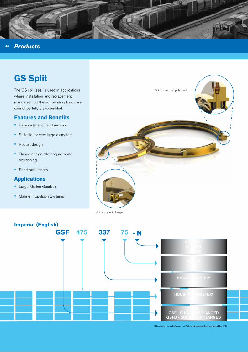
46 Products
GS Split
GSF
TYPE GSF - SiNGLE LiP FLANGED
GSFD - DoUBLE LiP FLANGED
Imperial (English)
475 337 75
WiDTH† 0.750”
SHAFT DiAMETER†
3.375”
HoUSiNG DiAMETER† 4.75”
†Dimension rounded down to 2 decimal places then multiplied by 100
The GS split seal is used in applications
where installation and replacement
mandates that the surrounding hardware
cannot be fully disassembled.
Features and benefits ▪ Easy installation and removal
▪ Suitable for very large diameters
▪ Robust design
▪ Flange design allowing accurate
positioning
▪ Short axial length
applications ▪ Large Marine Gearbox
▪ Marine Propulsion Systems
GSF - single lip flanged
GSFD - double lip flanged
MATERiALN – NBR F – FKM
- n
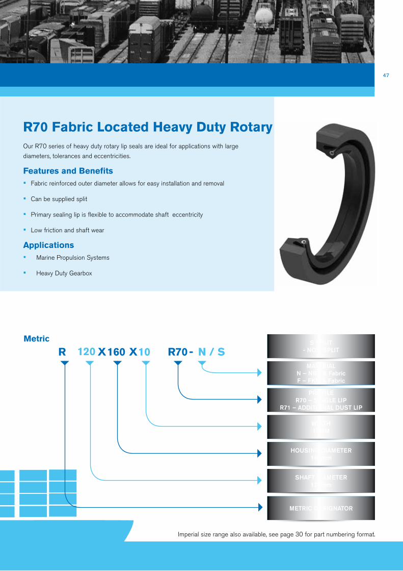
47
R70 Fabric Located Heavy duty Rotary Our R70 series of heavy duty rotary lip seals are ideal for applications with large
diameters, tolerances and eccentricities.
Features and benefits ▪ Fabric reinforced outer diameter allows for easy installation and removal
▪ Can be supplied split
▪ Primary sealing lip is flexible to accommodate shaft eccentricity
▪ Low friction and shaft wear
applications ▪ Marine Propulsion Systems
▪ Heavy Duty Gearbox
R
SHAFT DiAMETER 120mm
Metric
120 160 10 R70 n / SS SPLiT
- NoN-SPLiT
MATERiALN – NBR & FabricF – FKM & Fabric
PRoFiLER70 – SiNGLE LiP
R71 – ADDiTioNAL DUST LiP
WiDTH10MM
HoUSiNG DiAMETER 160mm
-XX
METRiC DESiGNAToR
Imperial size range also available, see page 30 for part numbering format.
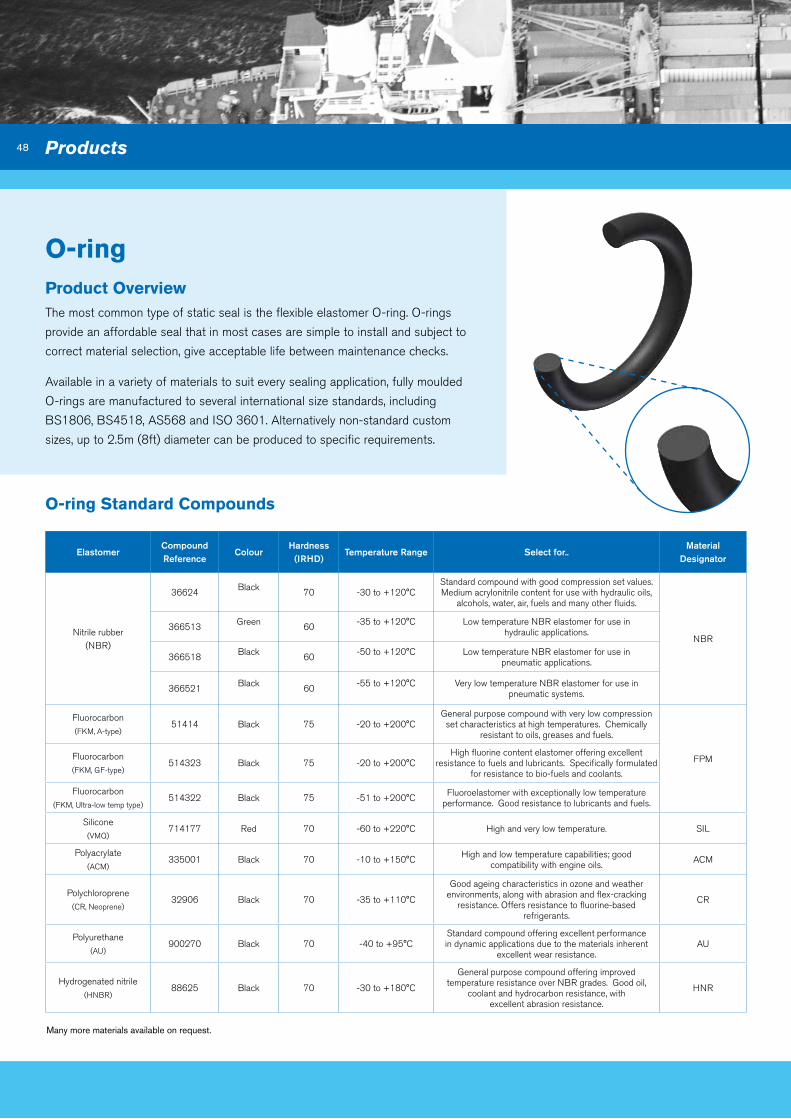
48
o-ring Product overview The most common type of static seal is the flexible elastomer O-ring. O-rings
provide an affordable seal that in most cases are simple to install and subject to
correct material selection, give acceptable life between maintenance checks.
Available in a variety of materials to suit every sealing application, fully moulded
O-rings are manufactured to several international size standards, including
BS1806, BS4518, AS568 and ISO 3601. Alternatively non-standard custom
sizes, up to 2.5m (8ft) diameter can be produced to specific requirements.
o-ring Standard Compounds
ElastomerCompound Reference
ColourHardness
(iRHD)Temperature Range Select for..
Material Designator
Nitrile rubber(NBR)
36624 Black 70 -30 to +120°CStandard compound with good compression set values. Medium acrylonitrile content for use with hydraulic oils,
alcohols, water, air, fuels and many other fluids.
NBR366513 Green 60 -35 to +120°C Low temperature NBR elastomer for use in
hydraulic applications.
366518 Black 60 -50 to +120°C Low temperature NBR elastomer for use in pneumatic applications.
366521 Black 60 -55 to +120°C Very low temperature NBR elastomer for use in pneumatic systems.
Fluorocarbon(FKM, A-type)
51414 Black 75 -20 to +200°CGeneral purpose compound with very low compression
set characteristics at high temperatures. Chemically resistant to oils, greases and fuels.
FPMFluorocarbon (FKM, GF-type)
514323 Black 75 -20 to +200°CHigh fluorine content elastomer offering excellent
resistance to fuels and lubricants. Specifically formulated for resistance to bio-fuels and coolants.
Fluorocarbon (FKM, Ultra-low temp type)
514322 Black 75 -51 to +200°C Fluoroelastomer with exceptionally low temperature performance. Good resistance to lubricants and fuels.
Silicone(VMQ)
714177 Red 70 -60 to +220°C High and very low temperature. SIL
Polyacrylate(ACM)
335001 Black 70 -10 to +150°C High and low temperature capabilities; good compatibility with engine oils. ACM
Polychloroprene(CR, Neoprene)
32906 Black 70 -35 to +110°C
Good ageing characteristics in ozone and weather environments, along with abrasion and flex-cracking
resistance. Offers resistance to fluorine-based refrigerants.
CR
Polyurethane(AU)
900270 Black 70 -40 to +95°CStandard compound offering excellent performance in dynamic applications due to the materials inherent
excellent wear resistance.AU
Hydrogenated nitrile (HNBR)
88625 Black 70 -30 to +180°C
General purpose compound offering improved temperature resistance over NBR grades. Good oil,
coolant and hydrocarbon resistance, with excellent abrasion resistance.
HNR
Many more materials available on request.
Products

49
†O-rings are supplied to ISO3601-1 class 2 tolerances unless otherwise specified.
†O-rings are supplied to ISO3601-1 class 2 tolerances unless otherwise specified.
139.3 -5.7 FPM 75 51414
*O-ring and hardware dimensional details are available at:
http://oring-groove-wizard.eriks.co.uk/DiameterGrooves.aspx
CoMPoUND REFERENCE51414 Viton®
HARDNESS 75 °iRHD ±5
MATERiAL FAMiLY DESiGNAToR FPM Viton®
NoMiNAL CRoSS SECTioN 5.70 mm
NoMiNAL iNNER DiAMETER 139.30 mm
bS -214 nbR 70 36624
CoMPoUND REFERENCE36624
HARDNESS 70 °iRHD ±5
MATERiAL FAMiLY DESiGNAToR NBR Nitrile
DASH SizE REFERENCE†
214
TYPE BS1806, AS-568, iSo3601-1
X
Imperial o-rings
Metric o-rings

50
X-ring Product overview X-rings can be used in a wide variety of static and dynamic sealing applications.
They are available in standard O-ring sizes.
Their four-lobed design provides a larger sealing area in comparison to a standard
O-ring. The double seal action requires lower squeeze levels to maintain an
effective seal, thus reducing friction level and improving seal life.
X-ring parting lines are between the lobes, away from the sealing surface,
therefore eliminating the problems of leakage often resulting from a parting lines
irregular surface as found on an O-ring.
X-rings are designed to out perform a standard O-ring in rotary seal applications.
The four lobed configuration creates a more stable seal avoiding spiral twisting
which can occur in reciprocating applications.
X-Rings
Q4 -210 nbR 70 36624
CoMPoUND REFERENCE36624
HARDNESS 70 °iRHD
MATERiAL FAMiLY DESiGNAToR NBR Nitrile
DASH SizE REFERENCE210
x-RiNG DESiGNAToR
Products

51
X-ring Materials
Q4
x-RiNG DESiGNAToR
139.3 5.7 FPM 75 51414
CoMPoUND REFERENCE51414
HARDNESS 75 °iRHD
MATERiAL FAMiLY DESiGNAToR FPM Viton®
CRoSS SECTioN 5.7 mm
iNNER DiAMETER 139.3 mm
X
Elastomer ColourHardness
(iRHD)Temperature Range Select for..
Compound Reference
Material Family Designator
Nitrile rubber (NBR) Black 70 -30 to +120°C
Standard compound with good compression set values. Medium acrylonitrile content for use with hydraulic oils, alcohols, water, air, fuels and many
other fluids.
36624 NBR
Fluorocarbon (FKM, A-type)
Black 75 -20 to +200°C
General purpose compound with very low compression set characteristics at high
temperatures. Chemical resistant to oils, greases and fuels.
51414 FPM
Metric X-Rings
*O-ring and hardware dimensional details are available at:
http://oring-groove-wizard.eriks.co.uk/DiameterGrooves.aspx

52
Typical Seal arrangement for CylindersERIKS Sealing Technology are able to specify and
provide complete sealing systems for your application.
Piston Seal and bearing
arrangement comprising
cap seal and bearing strips.
Products

53
Rod seal and bearing
arrangement comprising
Asymmetric U-cup, a metal
encased polyurethane
scraper, machined wear ring,
bearing strip and static
O-ring.
*O-ring and hardware dimensional details are available at:
http://oring-groove-wizard.eriks.co.uk/DiameterGrooves.aspx

54
Capped o-ring
CoP - - - -10000 C 36624 E491 - PWI
PTFE GRADE CoDEE491
ELASToMERiC ENERGiSER CoMPoUND REFERENCE
36624
BoRE/RoD DiAMETER150.00 mm
TYPECoP = PiSToN
CoR = RoD
RADiAL SECTioN CoDE A = 1.78B = 2.62C = 3.53D = 5.33E = 6.99
Product overview Capped O-rings are a cost-effective solution for providing cap seals for rod
and piston seal applications. The seal assembly consists of a cap manufactured
from one of ERIKS premier PTFE compounds and an O-ring to act as the seal
energiser.
The design of the capped O-ring protects the elastomer from extrusion and
nibbling. The specially profiled cap element acts as the seal’s dynamic interface
and prevents spiral failure and reduces stick slip, commonly associated with O-ring
seals.
Our capped O-rings are designed to retrofit existing O-ring
grooves, including AS4716 standard housing dimensions. Both
metric and imperial sizes are available and can be tailored to fit
housing dimensions provided. Our technical team can also advise
on how to optimise O-ring squeeze to minimise seal friction.
Products

55
*O-ring and hardware dimensional details are available at:
http://oring-groove-wizard.eriks.co.uk/DiameterGrooves.aspx
PTFE Grade Codes
Elastomeric Energiser Materials
Elastomer ColourHardness
(iRHD)Temperature
RangeSelect for..
Compound Reference
Silicone (VMQ) Red 70 -60 to +220°C High and very low temperature; high eccentricity 714177
Polyacrylate (ACM) Black 70 -10 to +150°CHigh temperature capabilities; good compatibility with
engine oils335001
Nitrile rubber (NBR) Black 70 -30 to +120°C General purpose 36624
Fluorocarbon (FKM, A-type)
Black 75 -20 to +200°C
High temperature performance; high speed applications; 514141 for improved coolant and fuel
resistance
51414
Green 75 -20 to +200°C 51414G
Fluorocarbon (FKM, GF-type)
Black 75 -10 to +200°C 514141
Hydrogenated nitrile (HNBR)
Black 70 -30 to +180°C High temperatures, moderate fuel resistance 88625
Material Composition
ColourCoefficient of
FrictionTemperature
RangeSelect for..
PTFE Reference
Virgin PTFE White 0.05 / 0.08 -240 to +200°C Static or low duty cycles E400
Glass and MoS2 reinforced PTFE
Grey / Black 0.06 / 0.10 -160 to +290°CDynamic or static, medium duty cycles, hardened metal
running surfacesE431
Graphite reinforced PTFE Black 0.06 / 0.10 -200 to +250°C Dynamic, medium duty cycles E471
Carbon and graphite reinforced PTFE
Black 0.08 / 0.12 -200 to +250°C Dynamic, medium duty cycles E462
Polyester reinforced PTFE Beige 0.08 / 0.12 -130 to +290°CDynamic or static, medium to high duty cycles, minimum
45 HRc running surfaceE491
Carbon, graphite and PPS reinforced PTFE
Grey/Black 0.08 / 0.12 -130 to +290°CDynamic or static, high duty cycles, hardened metal
running surfacesE282Z

56
double acting Cap Seal
C SP- - - -15000 d 36624 E471 - PWI
PTFE GRADE CoDE E471
ELASToMERiC ENERGiSER CoMPoUND REFERENCE
36624
RADiAL SECTioN CoDE A = 1.78B = 2.62C = 3.53D = 5.33E = 6.99
BoRE/RoD DiAMETER150.00 mm
TYPE SP – Piston Type Single Acting DP – Piston Type Double Acting
SR – Rod Type Single Acting DR – Rod Type Double Acting
Product overview A self-actuating, bi-directional, extrusion resistant seal that combines low breakout
and running friction with minimal leakage. The seal is constructed of a premium
grade PTFE sealing element and an elastomer energiser.
The Double Acting Cap Seal is a reliable, compact design with a long service
life and is available in both rod and piston type geometries to
retro-fit into ISO7425-2. Stick-slip is eliminated even after long
periods of inactivity whether in a lubricated or non-lubricated
environment, giving low breakout friction.
Standard Radial SectionsRadial Section
CodeStandard Bore / Rod diameter
(mm)Piston Groove Diameter (mm) Rod Groove Diameter (mm) Groove Width (mm)
A = 1.78 8 – 16.9 Bore Ø – 4.9 Rod Ø + 4.9 2.20
B = 2.62 17 – 26.9 Bore Ø – 7.3 Rod Ø + 7.3 3.20
C = 3.53 27 – 59.9 Bore Ø – 10.7 Rod Ø + 10.7 4.20
D = 5.33 60 – 199.9 Bore Ø – 15.1 Rod Ø + 15.1 6.30
E = 6.99 200 – 255.9 Bore Ø – 20.5 Rod Ø + 20.5 8.10
Products
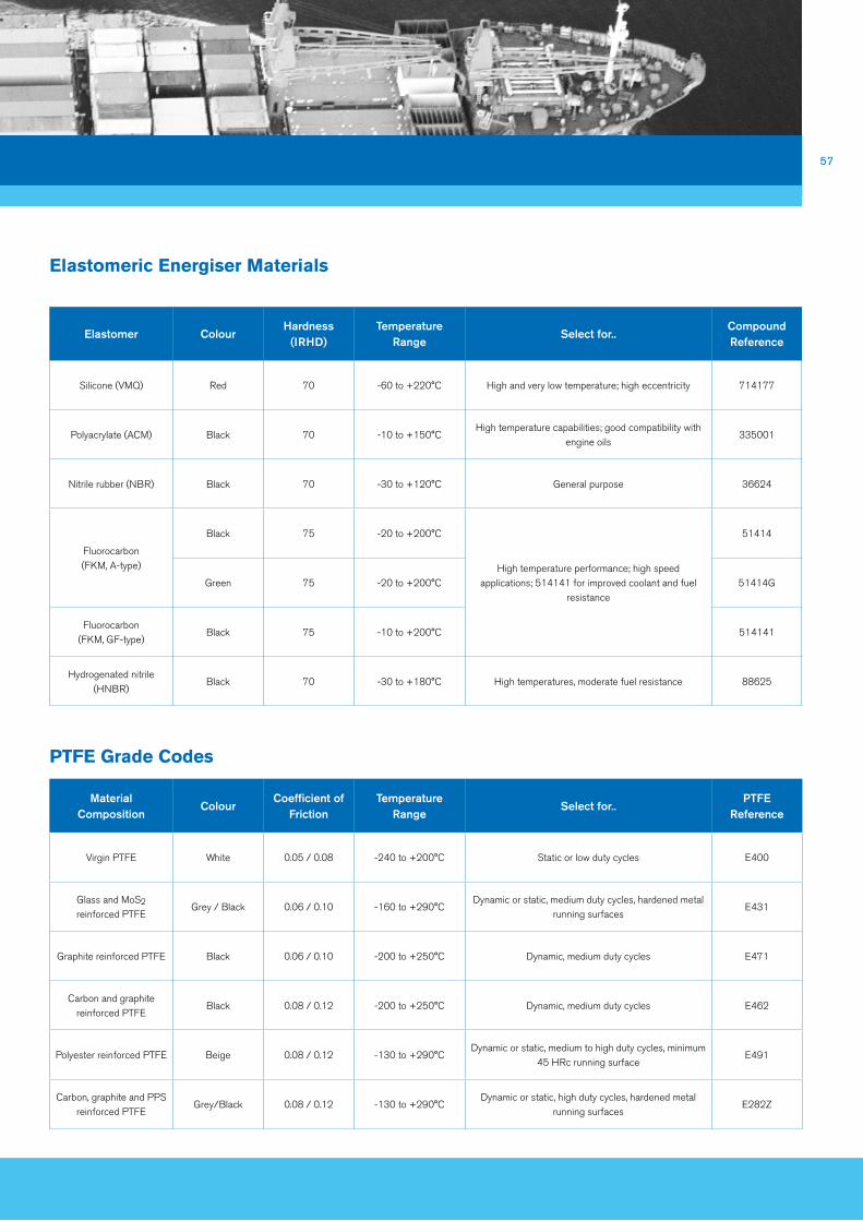
57
Elastomeric Energiser Materials
PTFE Grade Codes
Elastomer ColourHardness
(iRHD)Temperature
RangeSelect for..
Compound Reference
Silicone (VMQ) Red 70 -60 to +220°C High and very low temperature; high eccentricity 714177
Polyacrylate (ACM) Black 70 -10 to +150°CHigh temperature capabilities; good compatibility with
engine oils335001
Nitrile rubber (NBR) Black 70 -30 to +120°C General purpose 36624
Fluorocarbon (FKM, A-type)
Black 75 -20 to +200°C
High temperature performance; high speed applications; 514141 for improved coolant and fuel
resistance
51414
Green 75 -20 to +200°C 51414G
Fluorocarbon (FKM, GF-type)
Black 75 -10 to +200°C 514141
Hydrogenated nitrile (HNBR)
Black 70 -30 to +180°C High temperatures, moderate fuel resistance 88625
Material Composition
ColourCoefficient of
FrictionTemperature
RangeSelect for..
PTFE Reference
Virgin PTFE White 0.05 / 0.08 -240 to +200°C Static or low duty cycles E400
Glass and MoS2 reinforced PTFE
Grey / Black 0.06 / 0.10 -160 to +290°CDynamic or static, medium duty cycles, hardened metal
running surfacesE431
Graphite reinforced PTFE Black 0.06 / 0.10 -200 to +250°C Dynamic, medium duty cycles E471
Carbon and graphite reinforced PTFE
Black 0.08 / 0.12 -200 to +250°C Dynamic, medium duty cycles E462
Polyester reinforced PTFE Beige 0.08 / 0.12 -130 to +290°CDynamic or static, medium to high duty cycles, minimum
45 HRc running surfaceE491
Carbon, graphite and PPS reinforced PTFE
Grey/Black 0.08 / 0.12 -130 to +290°CDynamic or static, high duty cycles, hardened metal
running surfacesE282Z

58
T- SealPiston
Rod
Product overview Typically used in reciprocating and high pressure static applications, T-Seals
comprise a single T-section elastomeric energiser and two thermoplastic back-up
rings. Available in both piston and rod geometries, T-Seals can retro-fit into most
standard O-ring grooves designed for widths to accommodate 0, 1 or 2 back-ups.
The shape prevents spiral failure whilst reciprocating. The elastomer component
transmits the system pressure under the low pressure back-up ring, forcing
it into position, closing the extrusion gap. As an elastomeric contact seal, the
T-Seal provides highly efficient sealing and can be used in
applications where two fluid types need to be separated e.g. gas,
oil separation by an accumulator piston seal.
T1P- - - -bSI 214 36624 - PWI
BACK-UP MATERiAL REFERENCEE471
ELASToMER ENERGiSER CoMPoUND REFERENCE
36624
BACK-UP RiNG STYLEC=SCARF CUT S = SoLiD
GRooVE WiDTH0 = zero back-up ring width (Narrow)1 = Single back-up ring width (inter)2 = Double back-up ring width (Wide)
GRooVE DESiGN STANDARDBSi = BS1806, ASD = AS4716ASS = ASS857, iSo = iSo3601
BSM = BS4518
TYPET1P = PiSToN
T1R = RoD
C E471- -
SizE REFERENCE214
Products

59
Elastomeric Energiser Materials
back-Up Material Reference Codes
Elastomer ColourHardness
(iRHD)Temperature
RangeSelect for..
Compound Reference
Nitrile rubber (NBR) Black 70 -30 to +120°C General purpose 36624
Fluorocarbon (FKM, A-type)
Black 75
-20 to +200°CHigh temperature performance; high speed applications
51414
Green 75 51414G
Material Composition
ColourCoefficient of
FrictionTemperature
RangeSelect for..
PTFE Reference
Virgin PTFE White 0.05 / 0.08 -240 to +200°C Static or low duty cycles E400
Glass and MoS2 reinforced PTFE
Grey / Black 0.06 / 0.10 -160 to +290°CDynamic or static, medium duty cycles, hardened metal
running surfacesE431
Graphite reinforced PTFE Black 0.06 / 0.10 -200 to +250°C Dynamic, medium duty cycles E471
Carbon and graphite reinforced PTFE
Black 0.08 / 0.12 -200 to +250°C Dynamic, medium duty cycles E462
Polyester reinforced PTFE Beige 0.08 / 0.12 -130 to +290°CDynamic or static, medium to high duty cycles, minimum
45 HRc running surfaceE491
Carbon, graphite and PPS reinforced PTFE
Grey/Black 0.08 / 0.12 -130 to +290°CDynamic or static, high duty cycles, hardened metal
running surfacesE282Z
*O-ring and hardware dimensional details are available at:
http://oring-groove-wizard.eriks.co.uk/DiameterGrooves.aspx
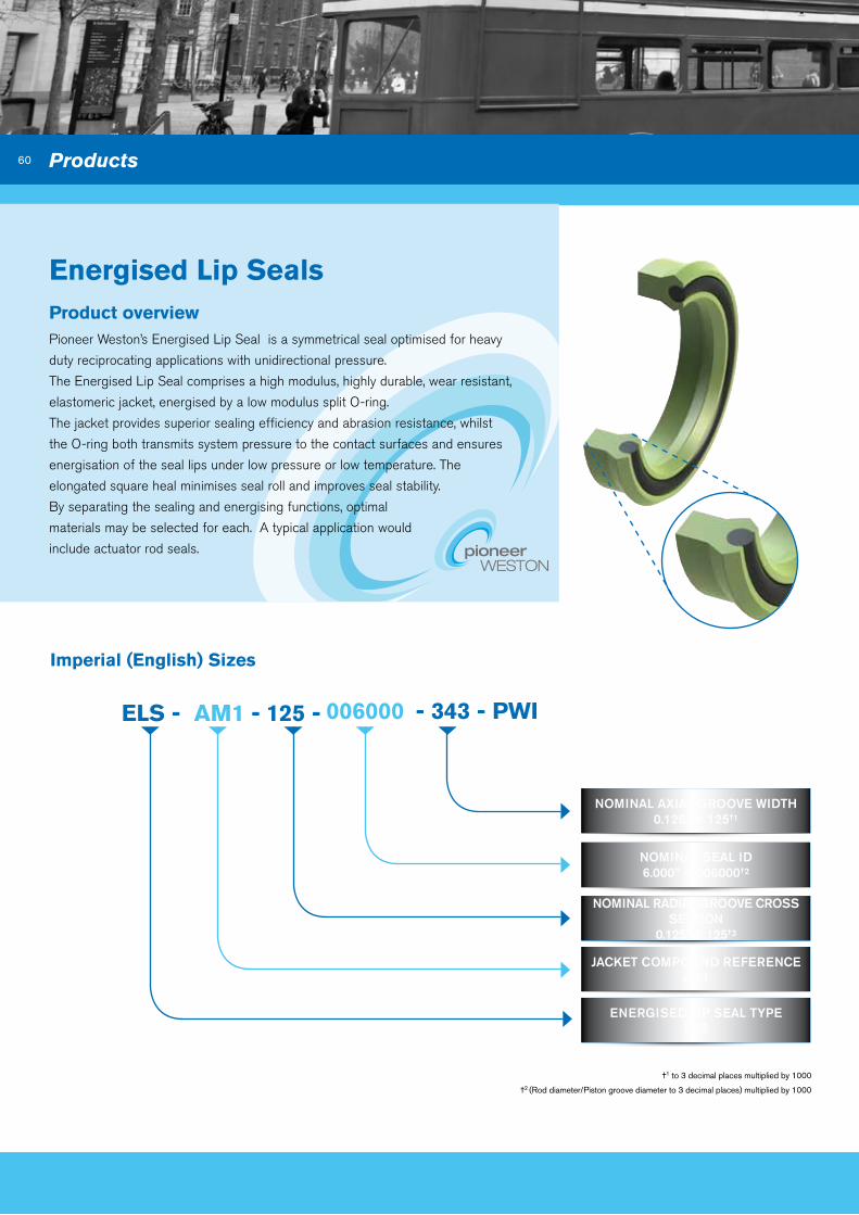
60
Energised Lip Seals
ELS -
ENERGiSED LiP SEAL TYPEELS
Imperial (English) Sizes
aM1 - 125 - 006000 - 343 - PWI
NoMiNAL AxiAL GRooVE WiDTH0.125” = 125†1
NoMiNAL SEAL iD6.000” = 006000†2
NoMiNAL RADiAL GRooVE CRoSS SECTioN
0.125” = 125†3
JACKET CoMPoUND REFERENCEAM1
†1 to 3 decimal places multiplied by 1000
†2 (Rod diameter/Piston groove diameter to 3 decimal places) multiplied by 1000
Product overview Pioneer Weston’s Energised Lip Seal is a symmetrical seal optimised for heavy
duty reciprocating applications with unidirectional pressure.
The Energised Lip Seal comprises a high modulus, highly durable, wear resistant,
elastomeric jacket, energised by a low modulus split O-ring.
The jacket provides superior sealing efficiency and abrasion resistance, whilst
the O-ring both transmits system pressure to the contact surfaces and ensures
energisation of the seal lips under low pressure or low temperature. The
elongated square heal minimises seal roll and improves seal stability.
By separating the sealing and energising functions, optimal
materials may be selected for each. A typical application would
include actuator rod seals.
Products

61
Compound References
Jacket MaterialCompound Reference
Energiser Material
ColourHardness
(iRHD)Temperature
RangeSelect for..
Material Designator
Polyurethane, moulded PU-90-203 NBR 70 Black 90 -40 to +100°CHydraulic ram rod seals for high volume
manufacture.AM1
Polyurethane, machined PU-90-202 NBR 70 Green 90 -40 to +100°CHydraulic ram rod seals for low volume
manufacture.AC1
Polyurethane, hydrolysis resistant
PU-95-166 NBR 70 Red 95 -40 to +100°CHydraulic ram rod seals in aqueous
environments- low volume manufacture.AH1
Nitrile rubber (NBR) N-90-204 NBR 70 Black 90 -35 to +110°CPiston applications for low – medium
pressureNJ1
Hydrogenated nitrile (HNBR), moulded
H-85-205 HNBR 70 Black 85 -40 to +180°CElevated temperatures, high abrasion
resistanceHJ1
Hydrogenate nitrile (HNBR), machined
H-85-206 HNBR 70 Black 85 -40 to +180°CElevated temperatures, high abrasion
resistance, low volume, rapid manufacture
HJ2
Fluorocarbon(FKM, A-type)
V-85-207 FKM 75 Green 85 -20 to +200°CHigh temperatures, increased chemical
resistance FJ1

62
asymmetric U-Cup
aUCP -
TYPEAUCP = PiSToN
AUCR = RoD
Imperial (English) Sizes
aM1 - 125 - 001000 - 375 - PWI
NoMiNAL AxiAL GRooVE WiDTH0.375” = 375†1
NoMiNAL SEAL iD (RoD DiAMETER)1.000” = 001000†2
NoMiNAL GRooVE RADiAL PACKiNG SPACE
0.125” = 125†3
MATERiAL DESiGNAToRAM1
Rod Type
PistonType
†1 to 3 decimal places multiplied by 1000
Product overview Pioneer Weston’s asymmetric U-cup is available in both piston and rod geometries
and offers a stand alone, robust solution for both hydraulic and pneumatic
reciprocating applications. The asymmetric U-cup may be used as the primary seal
in tandem rod arrangements, or back-to-back in piston applications due to the
venting lip design. Under low pressure the asymmetric U-cup exerts low friction
upon mating hardware requiring low actuation force. Available in a range of high
performance materials, the asymmetric U-cup offers exceptional performance
and service life, whilst minimising the required space envelope
required.
Symmetric U-cup designs are also available.
Products

63
Compound References
Jacket MaterialCompound Reference
ColourHardness
(iRHD)Temperature
RangeSelect for..
Material Designator
Polyurethane, moulded PU-90-203 Black 90 -40 to +100°CHydraulic ram rod seals for high volume
manufacture.AM1
Polyurethane, machined PU-90-202 Green 90 -40 to +100°CHydraulic ram rod seals for low volume
manufacture.AC1
Polyurethane, hydrolysis resistant
PU-95-166 Red 95 -40 to +100°CHydraulic ram rod seals in aqueous
environments- low volume manufacture.AH1
Nitrile rubber (NBR) N-90-204 Black 90 -35 to +110°C Piston applications for low – medium pressure NJ1
Hydrogenated nitrile (HNBR), moulded
H-85-205 Black 85 -40 to +180°C Elevated temperatures, high abrasion resistance HJ1
Hydrogenate nitrile (HNBR), machined
H-85-206 Black 85 -40 to +180°CElevated temperatures, high abrasion resistance,
low volume, rapid manufactureHJ2
Fluorocarbon(FKM, A-type)
V-85-207 Green 85 -20 to +200°C High temperatures, increased chemical resistance FJ1

64
Single acting Cap Seal
Standard Radial Sections
Radial Section Code
Standard Bore / Rod diameter (mm)
Piston Groove Diameter (mm) Rod Groove Diameter (mm) Groove Width (mm)
A = 1.78 8 – 16.9 Bore Ø – 4.9 Rod Ø + 4.9 2.20
B = 2.62 17 – 26.9 Bore Ø – 7.3 Rod Ø + 7.3 3.20
C = 3.53 27 – 59.9 Bore Ø – 10.7 Rod Ø + 10.7 4.20
D = 5.33 60 – 199.9 Bore Ø – 15.1 Rod Ø + 15.1 6.30
E = 6.99 200 – 255.9 Bore Ø – 20.5 Rod Ø + 20.5 8.10
CSP- - - -15000 d 36624 E471 - PWI
PTFE GRADE CoDE E471
ELASToMERiC ENERGiSER CoMPoUND REFERENCE
36624
BoRE/RoD DiAMETER150.00mm
TYPE CSP – Piston Type Single Acting DP – Piston Type Double Acting
SR – Rod Type Single Acting DR – Rod Type Double Acting
RADiAL SECTioN CoDE A = 1.78B = 2.62C = 3.53D = 5.33E = 6.99
Product overview A self-actuating, pressure venting, extrusion resistant seal that combines low
breakout and running friction with minimal leakage. The seal is constructed of a
premium grade PTFE sealing element and an elastomer energiser.
The Single Acting Cap Seal is a reliable, compact, design with a long service life
and is available in both rod and piston type geometries to retro-fit into
ISO7425-2. Stick-slip is eliminated even after long periods of inactivity whether
in a lubricated or non-lubricated environment, giving low breakout
friction.
Products
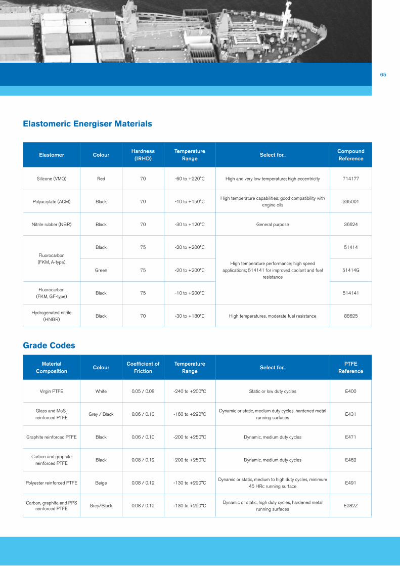
65
Elastomeric Energiser Materials
Grade Codes
Elastomer ColourHardness
(iRHD)Temperature
RangeSelect for..
Compound Reference
Silicone (VMQ) Red 70 -60 to +220°C High and very low temperature; high eccentricity 714177
Polyacrylate (ACM) Black 70 -10 to +150°CHigh temperature capabilities; good compatibility with
engine oils335001
Nitrile rubber (NBR) Black 70 -30 to +120°C General purpose 36624
Fluorocarbon (FKM, A-type)
Black 75 -20 to +200°C
High temperature performance; high speed applications; 514141 for improved coolant and fuel
resistance
51414
Green 75 -20 to +200°C 51414G
Fluorocarbon (FKM, GF-type)
Black 75 -10 to +200°C 514141
Hydrogenated nitrile (HNBR)
Black 70 -30 to +180°C High temperatures, moderate fuel resistance 88625
Material Composition
ColourCoefficient of
FrictionTemperature
RangeSelect for..
PTFE Reference
Virgin PTFE White 0.05 / 0.08 -240 to +200°C Static or low duty cycles E400
Glass and MoS2 reinforced PTFE
Grey / Black 0.06 / 0.10 -160 to +290°CDynamic or static, medium duty cycles, hardened metal
running surfacesE431
Graphite reinforced PTFE Black 0.06 / 0.10 -200 to +250°C Dynamic, medium duty cycles E471
Carbon and graphite reinforced PTFE
Black 0.08 / 0.12 -200 to +250°C Dynamic, medium duty cycles E462
Polyester reinforced PTFE Beige 0.08 / 0.12 -130 to +290°CDynamic or static, medium to high duty cycles, minimum
45 HRc running surfaceE491
Carbon, graphite and PPS reinforced PTFE
Grey/Black 0.08 / 0.12 -130 to +290°CDynamic or static, high duty cycles, hardened metal
running surfacesE282Z
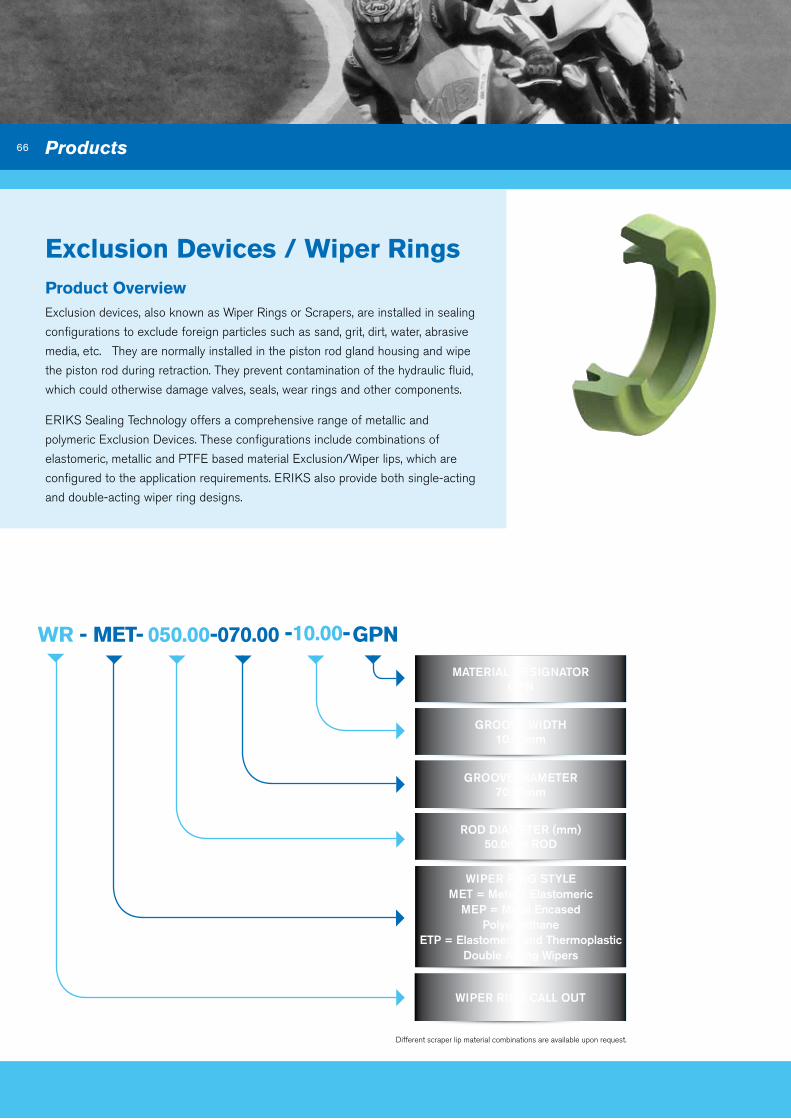
66
Exclusion devices / Wiper RingsProduct overview Exclusion devices, also known as Wiper Rings or Scrapers, are installed in sealing
configurations to exclude foreign particles such as sand, grit, dirt, water, abrasive
media, etc. They are normally installed in the piston rod gland housing and wipe
the piston rod during retraction. They prevent contamination of the hydraulic fluid,
which could otherwise damage valves, seals, wear rings and other components.
ERIKS Sealing Technology offers a comprehensive range of metallic and
polymeric Exclusion Devices. These configurations include combinations of
elastomeric, metallic and PTFE based material Exclusion/Wiper lips, which are
configured to the application requirements. ERIKS also provide both single-acting
and double-acting wiper ring designs.
- - -WR MET 050.00 070.00
MATERiAL DESiGNAToRGPN
GRooVE WiDTH10.00mm
GRooVE DiAMETER70.00mm
RoD DiAMETER (mm)50.0mm RoD
WiPER RiNG STYLEMET = Metal / Elastomeric
MEP = Metal EncasedPolyeurethane
ETP = Elastomeric and ThermoplasticDouble Acting Wipers
WiPER RiNG CALL oUT
GPn-10.00-
Different scraper lip material combinations are available upon request.
Products

67
Elastomeric Scrapers
The ME1 metal encased Elastomeric Scraper and ME2 Elastomeric covered metal
insert Scraper profiles can be installed into open grooves. The Elastomeric Scraper
element offers highly effective scraping performance and abrasion resistance, giving
proven protection to hydraulic and pneumatic cylinders by excluding dust, dirt, water,
etc. The standard elastomeric material for these profiles would be Nitrile (NBR).
Metal Encased Polyurethane Scraper
The MEP profile as like the Elastomeric Scraper seals can be installed into open
grooves. The profile comprises of a polyurethane (AU) scraper element housed in
a ground metal casing. The Metal Encased Polyurethane scraper element offers
improved scraping performance and abrasion resistance over the elastomeric
profiles in more demanding environments.
Elastomeric and Thermoplastic double acting Wipers
A Double acting wiper has either a sealing and a scraping lip in Nitrile (NBR) or
proprietary reinforced PTFE. It is optimised when used with rod seals that have
a back pumping capability. The double acting wiper is recommended for light to
medium duty and is available in alternative elastomeric/PTFE grades on request.
Material designator description Temperature Range
BPN Bronze reinforced PTFE / NBR 70 -30°C to +100°C
BPV Bronze reinforced PTFE / FKM 70 -20°C to +200°C
GPN Graphite reinforced PTFE / NBR 70 -30°C to +100°C
GPV Graphite reinforced PTFE / FKM 70 -20°C to +200°C
UPN UHMW-PE / NBR 70 -30°C to +80°C
UPV UHMW-PE / FKM 70 -20°C to +80°C
Material designator Codes

68
- -MWR bP -125.00 - 2.15
BoRE/RoD DiAMETER5mm To 999.99mm
GRooVE WiDTH (mm)
THiCKNESS (GRooVE DEPTH)
TYPE oF CUTA = Angled B = Butt
S = Stepped
MATERiAL DESiGNAToR
V = Virgin PTFE
C = Carbon Filled PTFE
B = Bronze Filled PTFE
F = Fabric Composite
BEARiNG oRiENTATioN P = Piston Type R = Rod Type
b-14.50-
MWR – Machined Wear Ring BT – Pre-cut Bearing Strip
Machined Wear Ring / bearing Strip Product overview The design intent of a Bearing Strip or Wear Ring is to guide the piston and/or
rod into a pneumatic or hydraulic cylinder. Any potential side or transverse loads
applied to the piston rod will be supported by the Wear Ring, thus preventing
contact between the static and sliding parts of the cylinder.
Wear Rings are non-metallic and offer advantages over traditional metallic
bearings. These benefits include improved load distribution, reduced friction, easy
installation and lower abrasion.
Different types of materials are available depending upon the application
requirements. PTFE based Wear Rings are for use in low to medium loads, fabric
composite Wear Rings are to be used under high load conditions.
Wear Rings are precision machined to mate with the customer’s hardware and are
available in a range of sizes, as defined by the below part numbering system.
Products

69
Machined Wear Ring dimensions
PiSToN BEARiNGS
Bearing Radial Thickness (mm)
Groove Width (+0.25/0.00)
Bearing Groove Diameterinternal Groove
Radii
1.00 6.00 Bore Diameter - 2.00/2.05mm
0.25mmMax
1.503.20
Bore Diameter - 3.00/3.05mm10.00
1.552.50
Bore Diameter - 3.10/3.15mm4.00
2.009.70
Bore Diameter - 4.00/4.05mm15.00
2.50
4.20
Bore Diameter - 5.00/5.05mm
5.60
6.30
8.10
9.70
15.00
20.00
25.00
30.00
3.00 20.00 Bore Diameter - 6.00/6.05mm
4.009.70
Bore Diameter - 8.00/8.05mm25.00
RoD BEARiNGS
Bearing Radial Thickness (mm)
Groove Width (+0.25/0.00)
Bearing Groove Diameterinternal Groove
Radii
1.00 6.00 Rod Diameter - 2.00/2.05mm
0.25mmMax
1.503.20
Rod Diameter - 3.00/3.05mm10.00
1.552.50
Rod Diameter - 3.10/3.15mm4.00
2.009.70
Rod Diameter - 4.00/4.05mm15.00
2.50
4.20
Rod Diameter - 5.00/5.05mm
5.60
6.30
8.10
9.70
15.00
20.00
25.00
30.00
3.00 20.00 Rod Diameter - 6.00/6.05mm
4.009.70
Rod Diameter - 8.00/8.05mm25.00
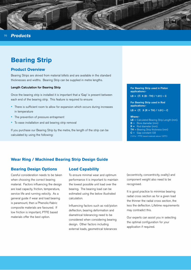
70
bearing StripProduct overviewBearing Strips are skived from material billets and are available in the standard
thicknesses and widths. Bearing Strip can be supplied in metre lengths.
Length Calculation for Bearing Strip
Once the bearing strip is installed it is important that a ‘Gap’ is present between
each end of the bearing strip. This feature is required to ensure:
▪ There is sufficient room to allow for expansion which occurs during increases
in temperature
▪ The prevention of pressure entrapment
▪ To ease installation and aid bearing strip removal
Wear Ring / Machined bearing Strip design Guide
bearing design optionsCareful consideration needs to be taken
when choosing the correct bearing
material. Factors influencing the design
are load capacity, friction, temperature,
service life and running velocity. As a
general guide if wear and load bearing
is paramount, then a Phenolic/fabric
composite materials are favoured. If
low friction is important, PTFE based
materials offer the best option.
Load Capability To ensure minimal wear and optimum
performance it is important to maintain
the lowest possible unit load over the
bearing. The bearing load can be
estimated using the below illustrated
calculation.
Influencing factors such as rod/piston
deflection, bearing deformation and
diametrical tolerancing need to be
considered when considering bearing
design. Other factors including
external loads, geometrical tolerances
(eccentricity, concentricity, ovality) and
component weight also need to be
recognised.
It is good practice to minimise bearing
radial cross section as for a given load
the thinner the radial cross section, the
less the deflection. Lifetime requirements
may contradict this.
Our experts can assist you in selecting
the optimal configuration for your
application if required.
Products
If you purchase our Bearing Strip by the metre, the length of the strip can be
calculated by using the following:
For Bearing Strip used in Piston applications:-
LB = (p x (B - TH) / 1.01) – C
For Bearing Strip used in Rod applications:-
LB = (p x (R + TH) / 1.01) – C
Where:-LB = Calculated Bearing Strip Length (mm).B = Bore diameter (mm)R = Rod diameter (mm).TH = Bearing Strip thickness (mm)C = Gap constant: 0.8 (1.8 for PTFE based materials above 120°C)
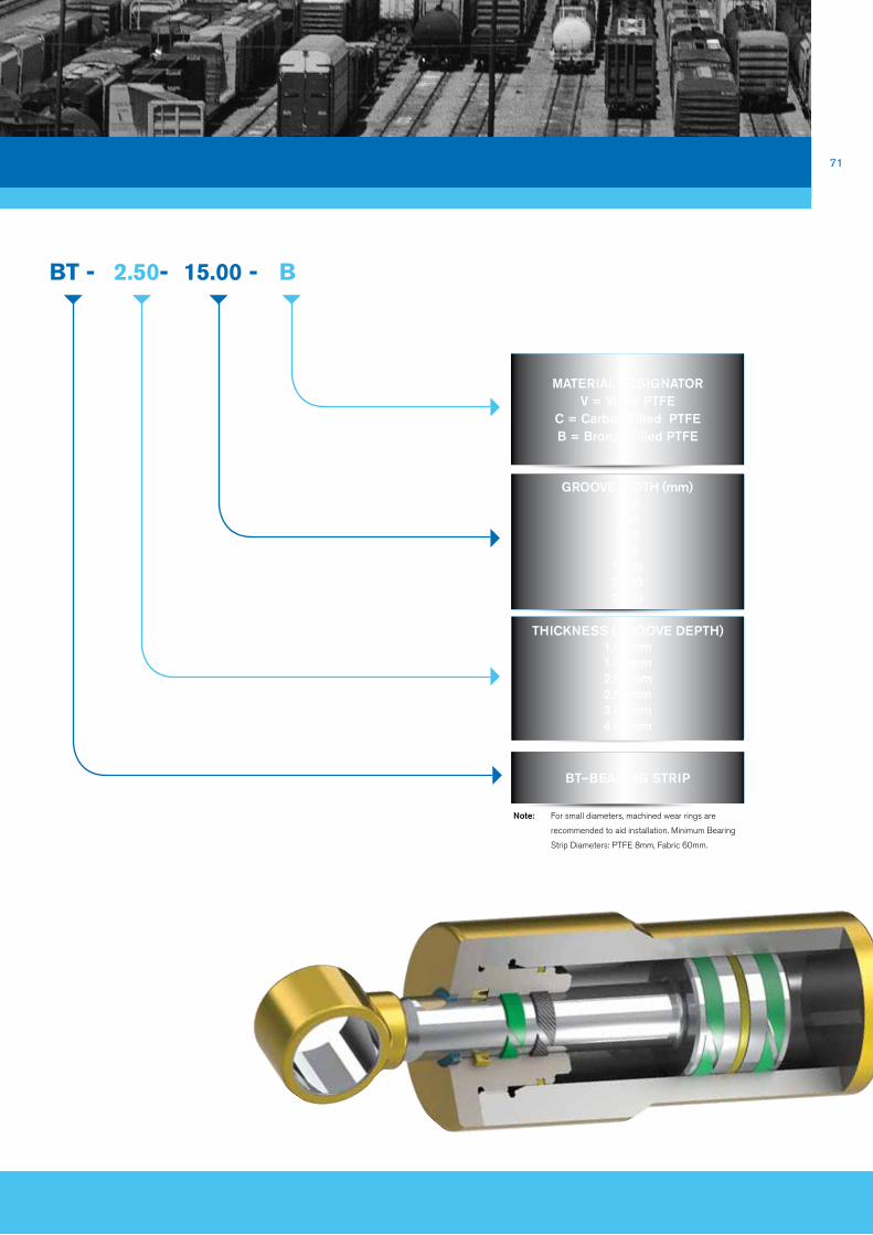
71
bT -
BT–BEARiNG STRiP
2.50- 15.00 - b
MATERiAL DESiGNAToRV = Virgin PTFE
C = Carbon Filled PTFEB = Bronze Filled PTFE
GRooVE WiDTH (mm)2.504.005.609.7015.0020.0025.00
THiCKNESS (GRooVE DEPTH)1.00mm1.55mm2.00mm2.50mm3.00mm4.00mm
Note: For small diameters, machined wear rings are
recommended to aid installation. Minimum Bearing
Strip Diameters: PTFE 8mm, Fabric 60mm.

72
bearing Calculation
For the Bearing Load Calculation we assume the load distribution is uniform over a project bearing area. The bearing area may be
approximated by using the following calculation:
Projected Bearing Area (Bpa) = Internal Bearing Diameter (Bd) X Bearing Axial Length (BL).
Products
e.g. Internal Bearing Diameter (Bd) = 50mm
Bearing Axial Length (BL) = 25mm
Projected Bearing Area (Bpa) = 1,250mm2
When the Projected Bearing Area (shaded red) has been approximated, the bearing pressure may be found by dividing the Total
Force Load by the Projected Bearing Area. This will determine the minimum compressive strength (Cs) of the bearing material to be
utilised. If your design requires the incorporation of a safety factor, it is advisable to multiply the Total Force Load (FL) by the desired
factor of safety (FOS), e.g. 2. The required bearing compressive strength can be calculated as follows:
Cs = FoS X FL
( bd X bL)
Cs = (2 X 3000n) (50mm X 25mm)
Cs = 6000 1250
= 4.8 MPa

73
Angle Cut Straight Cut
GA
P
Stepped Cut
GAP
GA
P GA
P
Type of CutAngled cuts are recommended for use in
reciprocating applications. Straight cuts
are for rotary applications. Stepped cuts
are used in special applications, e.g. for
flow restriction.
Machined Wear Rings are application
specific. Based upon application data,
the appropriate dimensions and hardware
tolerances will be calculated by our
technical team for the entire sealing
system.
Material Selection
MaterialCompressive
Strength (Max)Max Surface Speed Mating Surface Size Availability General Uses
Bronze filled PTFE15 MPa at 25 °C12 MPa at 80 °C8 MPa at 120 °C
15.0 m/s
Steel Hard Chrome, Steel Hardened Rings 8mm to
2600mm
Up to 4600 in Strip form
Light load, lubricated environment
Carbon filled PTFE12 MPa at 25 °C9 MPa at 80 °C
5 MPa at 120 °C
Stainless Steel, Hard Anodised Aluminium
Light duty, can run dry
Phenolic(Fabric composite)
300 MPa at 25 °C(Static)
50 MPa at 60°C(Dynamic)
1.0 m/sSteel Hard Chrome, Steel
Hardened10mm to 1500mm
(Rod Dia)Heavy load, lubricated
environment
Calculating the required bearing material strength is important in determining the correct material to use. Listed below are
additional criteria that need to be considered:
▪ Is the application rotary, reciprocating or static?
▪ What surface speed will the bearing see?
▪ Is lubrication present?
▪ What are the temperature extremes?
▪ What is the shaft/bore material, hardness and surface finish?
▪ Does the bearing have exposure to abrasive, erosive and chemically aggressive media?

74 Additional Products and Services
bellows, diaphragms and Cover SealsA wide range of custom moulded diaphragms and bellows are available. We offer
expertise when selecting the correct compound, optimising modulus to achieve
specified force deflection characteristics and life.
These components are available with fabric reinforcement
to provide increased stiffness and pressure capability.
Circlips, also known as retaining rings, are typically used to maintain the axial location
of bearings and seals within housings. Available in metric (DIN 471/DIN 472)
and imperial sizing, circlips are typically produced in high performance spring steel,
although other materials, including stainless steel and phosphor-bronze are available
upon request.
External circlips fit around the outside diameter of a shaft, and internal circlips are
installed into a housing bore recess.
Circlips

75
buffers and bump StopsCustom design structural components to act as buffers and bump stops can be
either moulded or extruded in traditional thermo-set elastomers, or in thermoplastic
elastomer grades.
Traditional elastomers offer a wider variety of chemical compatibilities.
Thermoplastic elastomer grades offer reduced environmental
impact, due to reduced energy demand in
manufacture and they may be recycled.
Advice on design and the incorporation of moulded
features for location is readily available from
our expert technical staff.
V-rings are an elastomer axial seal for shafts and bearings, installed onto the shaft
or counterface. This type of seal has been used widely for many applications and
has proved to be reliable and effective against dust, dirt, water, oil splash and other
media.
v-rings
A Type L Type
S Type RME Type

76 Additional Products and Services
Rubber Moulded and Extruded ProductsRubber MouldingsThe moulding of rubber and elastomeric
compounds is accomplished by forcing
the material into a shape using heat and
pressure. Rubber and elastomers can
be moulded by compression, transfer and
injection methods. The volume of parts
and type of compound required
will determine the moulding method used.
Our engineers participate with
you to develop innovative solutions for
your production.
Extruded Rubber Profiles/InflatablesOur comprehensive product range
incorporates not only rubber, but also
Thermo Plastic Elastomer (TPE).
Our in-house CAD/CAM capability
also enables us to quickly design and
accurately manufacture innovative
solutions to meet new applications and
operating conditions utilising our in-house
3D rubber printing capabilities.
Metal bonded Seals
Many of our elastomer grades are available as co-moulded (bonded) components.
Typical applications ▪ Gaskets
▪ Covers
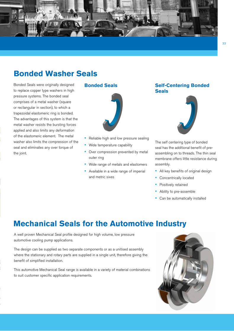
77
bonded Washer SealsBonded Seals were originally designed
to replace copper type washers in high
pressure systems. The bonded seal
comprises of a metal washer (square
or rectangular in section), to which a
trapezoidal elastomeric ring is bonded.
The advantages of this system is that the
metal washer resists the bursting forces
applied and also limits any deformation
of the elastomeric element. The metal
washer also limits the compression of the
seal and eliminates any over torque of
the joint.
bonded Seals
▪ Reliable high and low pressure sealing
▪ Wide temperature capability
▪ Over compression prevented by metal
outer ring
▪ Wide range of metals and elastomers
▪ Available in a wide range of imperial
and metric sixes
Self-Centering bonded Seals
The self centering type of bonded
seal has the additional benefit of pre-
assembling on to threads. The thin seal
membrane offers little resistance during
assembly.
▪ All key benefits of original design
▪ Concentrically located
▪ Positively retained
▪ Ability to pre-assemble
▪ Can be automatically installed
Mechanical Seals for the automotive IndustryA well proven Mechanical Seal profile designed for high volume, low pressure
automotive cooling pump applications.
The design can be supplied as two separate components or as a unitised assembly
where the stationary and rotary parts are supplied in a single unit, therefore giving the
benefit of simplified installation.
This automotive Mechanical Seal range is available in a variety of material combinations
to suit customer specific application requirements.

78
valve Stem Seals
Additional Products and Services
Valve stem seals are engineered to control the amount of lubrication to the engine
valves by allowing the right amount of oil to pass the seal lip. This has a direct impact
on efficiency and reliable life of the engine. Too much oil can result in increased engine
emissions and too little lubrication allowed to enter the system can result in
engine failure.
Valve stem seals are designed in a number of
varied profiles and materials to suit specific
customer application conditions. These design
considerations are applied when engineering
a suitable solution.
Kitting and bagging ERIKS Sealing Technology can provide bespoke kits
and aftermarket bagging of individual parts to service
your industry requirements.
Our specially tailored kits are assembled and
packaged with clearly marked part numbering and
can be supplied with our own brand, or alternatively,
customer specific branding.
We are able to offer kits that include a variety of our
core product, ranging from Rotary Seals and O-rings
to Hydraulic Seals, Washers and Gaskets.

79
other brochures in this Series
ERIKS Sealing Technology Engineered Seals for Agriculture and Earth Moving Applications
ERIKS Sealing Technology Polymer Sealing Solutions for the Chemical Process Industry
ERIKS Sealing Technology Engineered Polymer Solutions for Oil & Gas Applications

ERIKS Sealing Technology ERIKS Sealing Technology offers a comprehensive range of high performance sealing
products, supported by a world-class technical and logistical service to deliver the right
seal on time to your critical applications.
ERIKS Sealing Technology Unit 5, Yorks Park blowers Green Roaddudley West MidlandsdY2 8UL
Tel 0845 603 1221Fax 0845 603 1441 www.eriks.co.uk
ERIKS Sealing Technology206 Cavendish Placebirchwood ParkWarringtonCheshireWa3 6WU
Tel 01925 853000Fax 01925 853030
www.pioneerweston.com