Embed Size (px)
Citation preview

By: Georgia Institute of Technology Team Autonomous Rocket
Equipment System (A.R.E.S.)
Georgia Institute of Technology North Avenue NW Atlanta GA, 30332
Project Name: Hermes MAXI-MAV Competition
Friday, November 6, 2015

2014-2015 Georgia Tech Team ARES Preliminary Design Review
Page 1 of 72
Table of Contents 1 Introduction ............................................................................................................................. 5
1.1 Team Summary ................................................................................................................ 5
1.2 Work Breakdown Structure .............................................................................................. 5
1.3 Launch Vehicle Summary ................................................................................................ 6
1.3.1 Overview ................................................................................................................... 6
1.3.2 Changes since Proposal............................................................................................. 6
1.4 AGSE Summary ............................................................................................................... 7
1.4.1 Overview ................................................................................................................... 7
1.4.1 Changes since Proposal............................................................................................. 7
2 Project Hermes Overview ....................................................................................................... 8
2.1 Mission Statement ............................................................................................................ 8
2.2 Mission Objectives and Mission Success Criteria ........................................................... 8
2.2.1 Launch Vehicle ......................................................................................................... 8
2.2.2 Autonomous Ground Support Equipment ................................................................ 9
3 Launch Vehicle ..................................................................................................................... 10
3.1 Overview ........................................................................................................................ 10
3.2 Mission Success Criteria ................................................................................................ 12
3.3 System Design Overview ............................................................................................... 12
3.4 Recovery System ............................................................................................................ 14
3.4.1 Parachute Requirements.......................................................................................... 15
3.4.2 Parachute Dimensions ............................................................................................. 15
3.4.3 Drift Profile Analysis .............................................................................................. 16
3.4.4 Kinetic Energy of Launch Vehicle ......................................................................... 19

2014-2015 Georgia Tech Team ARES Preliminary Design Review
Page 2 of 72
3.4.5 Ejection Charges ..................................................................................................... 19
3.4.6 Testing..................................................................................................................... 20
3.5 Launch Vehicle Performance Analysis .......................................................................... 21
3.5.1 Fin Design ............................................................................................................... 21
3.5.2 CP and CG .............................................................................................................. 23
3.5.3 Nose Cone ............................................................................................................... 27
3.5.4 Motor Selection ....................................................................................................... 28
3.5.5 Booster Section ....................................................................................................... 29
3.5.6 Altitude Predictions ................................................................................................ 31
3.5.7 Apogee Targeting System Analysis ........................................................................ 31
3.5.8 Fabrication and Materials ....................................................................................... 36
3.5.9 Future Testing and Analysis ................................................................................... 37
3.6 Mass Breakdown ............................................................................................................ 37
3.7 Confidence and Maturity of Design ............................................................................... 38
3.8 Interfaces and Integration ............................................................................................... 39
3.8.1 Interfaces with the Ground...................................................................................... 40
3.8.2 Interfaces with AGSE ............................................................................................. 40
3.9 Launch Vehicle Operations ............................................................................................ 40
4 Autonomous Ground Support Equipment ............................................................................ 41
4.1 Overview ........................................................................................................................ 41
4.2 Mission Success Criteria ................................................................................................ 41
4.3 System Design Overview ............................................................................................... 42
4.4 Robotic Delivery Payload System ................................................................................. 44
4.5 Rocket Erection System (RES) ...................................................................................... 47
4.6 Motor Ignition System (MIS) ......................................................................................... 48

2014-2015 Georgia Tech Team ARES Preliminary Design Review
Page 3 of 72
4.7 Electronics ...................................................................................................................... 49
4.7.1 Power ...................................................................................................................... 49
4.7.2 Microcontroller ....................................................................................................... 49
4.8 Component Testing ........................................................................................................ 51
5 Flight Systems ....................................................................................................................... 52
5.1 Overview ........................................................................................................................ 52
5.2 Success Criteria .............................................................................................................. 52
5.3 Flight Systems Avionics Bay ......................................................................................... 52
5.4 Altimeters ....................................................................................................................... 54
5.5 Apogee Targeting System Electronics ........................................................................... 55
5.6 Component Testing ........................................................................................................ 56
5.7 GPS................................................................................................................................. 57
5.8 Power .............................................................................................................................. 57
6 Safety .................................................................................................................................... 59
6.1 Overview ........................................................................................................................ 59
6.2 Launch Vehicle Safety ................................................................................................... 61
6.3 AGSE Safety .................................................................................................................. 63
6.4 Environmental Concerns ................................................................................................ 63
7 Project Plan ........................................................................................................................... 64
7.1 Project Schedule ............................................................................................................. 64
7.2 Schedule Risk ................................................................................................................. 64
7.2.1 High Risk Tasks ...................................................................................................... 64
7.2.2 Low-to-Moderate Risks Tasks ................................................................................ 65
7.3 Critical Path .................................................................................................................... 67
8 Project Budget ....................................................................................................................... 68

2014-2015 Georgia Tech Team ARES Preliminary Design Review
Page 4 of 72
8.1 Funding Plan .................................................................................................................. 68
8.2 Current Sponsors ............................................................................................................ 68
8.3 Projected Project Costs................................................................................................... 69
8.4 Budget Summary ............................................................................................................ 69
9 Education Engagement Plan and Status ................................................................................ 70
9.1 Overview ........................................................................................................................ 70
9.2 Atlanta Maker’s Faire..................................................................................................... 70
9.3 FIRST Lego League ....................................................................................................... 71
9.4 CEISMC GT ................................................................................................................... 71
10 Appendix I ............................................................................................................................ 72

2014-2015 Georgia Tech Team ARES Preliminary Design Review
Page 5 of 72
1 Introduction
1.1 Team Summary
Team Summary
School Name Georgia Institute of Technology
Mailing Address North Avenue NW, Atlanta GA 30332
Team Name Team Autonomous Rocket Equipment System (A.R.E.S.)
Project Title Hermes
Launch Vehicle Name Skyron
Project Lead Victor R.
Safety Officer Stephen K
Team Advisors Dr. Eric Feron
NAR Section Primary: Southern Area Launch vehiclery (SoAR) #571
NAR Contact, Number & Certification Level
Primary Contact: Joseph Mattingly
NAR/TRA Number: 92646
Certification Level: Level 2
Secondary: Jorge Blanco
1.2 Work Breakdown Structure
Team Autonomous Rocket Erector System (ARES) is composed of twenty-one students studying
varying fields of engineering. Our team is composed of less than 50% Foreign Nationals (FN) per
NASA competition requirements. To work more effectively, the team is broken down into groups
that focus on special tasks. Each sub-team has a general manager supported by several technical
leads and subordinate members. Team memberships were selected based on each individual's area
of expertise and personal interest. Figure 1 shows the work breakdown structure of Team ARES.

2014-2015 Georgia Tech Team ARES Preliminary Design Review
Page 6 of 72
Figure 1: Team Breakdown Structure
1.3 Launch Vehicle Summary
1.3.1 Overview
The Skyron Launch Vehicle is 90.16 inches in length and projected to weigh 22.22 lb. with a 30%
mass margin. Skyron is designed to accommodate a 3.5 inch PVC pipe payload in the payload bay
located just before the nose cone. A Cesaroni Technology L820 reloadable rocket motor was
chosen to propel the rocket to an apogee of 5280 ft. A 2.5 foot diameter drogue parachute will
deploy from a compartment between the booster and avionics sections an apogee, and a 4.3 ft.
diameter main parachute will be deployed below 700 ft. AGL to slow the rocket such that the
kinetic energy at ground impact will be below 75 ft-lbf.
1.3.2 Changes since Proposal
x New Design of the ATS system to open tabs horizontally out from the body to an angle of
45 degrees with the rocket body instead of the previous ninety degree translation
x ATS system will be powered by four push-pull solenoids to extend the tabs
x Switch the location of the Main and Drogue Parachutes
x Motor Selection: L820 (with L990 in consideration)

2014-2015 Georgia Tech Team ARES Preliminary Design Review
Page 7 of 72
1.4 AGSE Summary
1.4.1 Overview
The Autonomous Ground Support Equipment (AGSE) will have a robotic arm that can grab a
payload that is off the platform and secure said payload inside the launch vehicle. The Rocket
Erection System (RES) will then raise the launch vehicle from a horizontal position to a position
5 degrees from the vertical. The Motor Ignition System (MIS) will then insert an electronic match
12 inches into the motor to ignite the motor. The overall system will be largely constructed from
1010 rails and have a 10 ft. by 2 ft. base and be 1.5 ft. in height and weight approximately 60 lbs.
1.4.1 Changes since Proposal
x Switch REM from linear actuator to spool raising mechanism
x Incorporating claw design for RDPS

2014-2015 Georgia Tech Team ARES Preliminary Design Review
Page 8 of 72
2 Project Hermes Overview
2.1 Mission Statement
The mission of Team ARES is:
To maintain a sustainable team dedicated to the gaining of knowledge through the designing,
building, and launching of reusable launch vehicles with innovative payloads in accordance with
the NASA University Student Launch Initiative Guidelines.
2.2 Mission Objectives and Mission Success Criteria
2.2.1 Launch Vehicle Table 1: Mission Success Criteria for Skyron
Requirement Design feature to satisfy that requirement
Requirement Verification
Success Criteria
Reach an altitude of 5,280 ft. as accurately
as possible.
The A.T.S. will deploy during cruise flight to adjust the flight profile curve to match a real-time ideal projection of the rocket’s trajectory for the
designated altitude by increasing the drag coefficient of the launch
vehicle.
Gathering data post-launch from the on-
board altimeters.
The A.T.S. directs the
launch vehicle to an accuracy in apogee of 2%.
The vehicle must be reusable.
Robust materials will be selected for the components of the launch vehicle that will be subjected to
high-stress environments.
By inspecting every element of the
launch vehicle to ensure no structure was compromised
No visible structural damage is
visible and every component is still functional
The payload must be retained
at all times during flight
A payload bay with secure payload holders will provide
sufficient force to prevent detachment due to vibrations.
By inspecting the payload bay post-
launch for partial or complete
detachment.
The payload will remain in the
same position as it was pre-
launch.

2014-2015 Georgia Tech Team ARES Preliminary Design Review
Page 9 of 72
2.2.2 Autonomous Ground Support Equipment Table 2: Mission Success Criteria for AGSE
Requirement Design feature to satisfy that requirement
Requirement Verification
Success Criteria
Pick up the Payload from a location at least 12” away from the launch vehicle and place the Payload inside the launch vehicle
The RDPS System is a 3-DOF arm that will automatically detect the location of the payload using IR sensors and place the payload inside the payload bay
Testing the RDPS Subsystem on the ground to ensure accurate completion of task
The RDPS has successfully placed the payload and secured the hatch; all autonomously
Raise the launch vehicle to 5 degrees off the vertical
The REM system will use an arm-spool mechanism to raise the rail the launch vehicle is sitting on effectively and safely
Testing the REM Subsystem on the ground to ensure completion of the task
Accurate measurement of the system to exactly 5 degrees off the vertical
Insert an Igniter into the launch vehicle motor
The MIS System will use a rack and pinion to system to place the igniter 12” inside the rocket motor
Testing the REM Subsystem on the ground to ensure completion of the task
The Igniter is securely placed inside the solid rocket motor

2014-2015 Georgia Tech Team ARES Preliminary Design Review
Page 10 of 72
3 Launch Vehicle
3.1 Overview
The purpose of the launch vehicle Skyron is to achieve a precise altitude of 5280 ft., whiling
retaining a payload and gathering flight data throughout the full length of the flight. Skyron must
successfully launch, reach the altitude, deploy the recovery system at the correct altitude, and land
without any structural damage. During the ascent of the vehicle, it must actively target the desired
altitude using electronic guidance in order to attain the highest level of precision possible. The
project also requires an extensive phase of design, manufacturing and testing that will be carried
out with the highest safety standards and most efficient procedures as is reasonably possible. The
main structure of the launch vehicle is illustrated below in Figure 2.
The dimensions of the launch vehicle were specifically determined in order to be able to achieve
the mission requirements detailed in the previous section, and also to accommodate the various
systems efficiently and effectively, while still maintaining a high stability margin to ensure the
safety of the operation. The specific dimensions are as follows in Table 3.
Figure 2: General Layout of Launch Vehicle

2014-2015 Georgia Tech Team ARES Preliminary Design Review
Page 11 of 72
Table 3: Length of the components of the launch vehicle
Parameter Value
Overall Length 90 in
Booster Section 29 in
Avionics Section 18 in
Payload Section 25 in
Body Diameter 5 in
Nose Cone Length 18 in
Fin Height 5.3 in
Fin Root Chord 7.5 in
Fin tip Chord 3.1 in
The dimensions for the systems that are categorized as inner components of the launch system are
detailed below in Table 4.
Table 4: Dimensions of the inner components of the launch vehicle
Parameter Value
Payload Bay 6.2 in
Avionics Bay 11 in
ATS 4.2 in
Motor Casing 20.4 in
Couplers 7 in
Bulkheads & Centering Rings (Thickness) 0.25 in
The launch vehicle, from aft to front, consists of three detachable segments: the booster section,
the avionics section, and the payload section. Skyron will utilize a dual-deployment recovery
system that will minimize the drift of the launch vehicle by mitigating the effects of wind
conditions. However, to still achieve the purpose of a reusable launch vehicle, a main parachute
will be deployed during the descent to ensure a safe landing.

2014-2015 Georgia Tech Team ARES Preliminary Design Review
Page 12 of 72
3.2 Mission Success Criteria Table 5: Mission Success Criteria for Skyron
Requirement Design feature to satisfy that requirement
Requirement Verification
Success Criteria
Reach an altitude of 5,280 ft. as accurately
as possible.
The A.T.S. will deploy during cruise flight to adjust the flight profile curve to match a real-time ideal projection of the rocket’s trajectory for the
designated altitude by increasing the drag coefficient of the launch
vehicle.
Gathering data post-launch from the on-
board altimeters.
The A.T.S. directs the
launch vehicle to an accuracy in apogee of 2%.
The vehicle must be reusable.
Robust materials will be selected for the components of the launch vehicle that will be subjected to
high-stress environments.
By inspecting every element of the
launch vehicle to ensure no structure was compromised
No visible structural damage is
visible and every component is still functional
The payload must be retained
at all times during flight
A payload bay with secure payload holders will provide
sufficient force to prevent detachment due to vibrations.
By inspecting the payload bay post-
launch for partial or complete
detachment.
The payload will remain in the
same position as it was pre-
launch.
3.3 System Design Overview Table 6: Launch Vehicle Requirements
Requirement Design Feature to Satisfy Requirement
Verification Method
Status
Vehicle altimeter will report an apogee altitude of most nearly 5,280 feet AGL.
Low-mounted electric-controlled fins will be extended and retracted in reaction to altimeter readings to control drag and limit altitude.
Analysis In Progress
Launch vehicle will be designed to be recoverable and reusable within the day of initial launch.
Vehicle will be constructed of fiberglass to resist fractures and ensure stability.
Design Review
In Progress
Vehicle will be prepared within 2 hours and will be able to
Compartmentalized design with standard assembly procedure.
Execution In Progress

2014-2015 Georgia Tech Team ARES Preliminary Design Review
Page 13 of 72
Requirement Design Feature to Satisfy Requirement
Verification Method
Status
maintain launch-ready position for at least 1 hour.
The launch vehicle shall have a maximum of four (4) independent sections.
Three (3) sections include: payload, avionics, and booster
Inspection In Progress
The vehicle will be limited to a single stage, solid motor propulsion system, delivering an impulse of no more than 5,120 Newton-seconds.
Single-staged design that utilizes a single “L” impulse classification motor.
Design Review
In Progress
Team must launch and recover both a subscale and full scale model prior to each CDR and FRR respectively.
Efficient Recovery System with redundancies to ensure successful operation.
Execution In Progress
The launch vehicle shall stage the deployment of its recovery devices, where a drogue parachute is deployed at apogee and a main parachute is deployed at a much lower altitude.
Redundant altimeters programmed to deploy at specific altitudes.
Inspection In Progress
At landing, the launch vehicle shall have a maximum kinetic energy of 75 ft-lbf.
Optimization of parachute sizing for the total mass of the launch vehicle
Testing In Progress
The recovery system will contain redundant altimeters, each with their own power supply and dedicated arming switch located on the exterior of the rocket airframe
Install a master key-switch at the rear of the avionics bay to close all circuits simultaneously, and independent compartment for sensors and power supply.
Inspection In Progress
Each detachable section of the vehicle and payload must contain an electronic tracking device and continue transmission to the ground throughout flight and landing.
Independent GPS compartment with transmission capabilities and ground station with receiving capabilities.
Inspection In Progress

2014-2015 Georgia Tech Team ARES Preliminary Design Review
Page 14 of 72
3.4 Recovery System
The main parachute will be housed above the avionics section while the drogue will be located
within Skyron’s booster section, as shown in Figure 3. The location of our parachutes were chosen
to effectively distribute the weight through the vehicle thereby maintaining the vehicle’s stability.
Figure 3: Parachute Locations
Parachutes made of rip-stop nylon were selected in order to ensure that both chutes support the
weight of the rocket. Both parachutes will be protected by an insulated material in order to reduce
the likelihood of combustion from sparks generated by the explosive charge used to separate the
upper and lower section of the rocket’s main body during descent. The parachutes will be secure
to U-bolts located on bulkheads/centering rings insulting both the upper and lower sections from
variations in pressure.

2014-2015 Georgia Tech Team ARES Preliminary Design Review
Page 15 of 72
3.4.1 Parachute Requirements
3.4.2 Parachute Dimensions
Parachutes were sized in accordance to equations highlighted in Figure 4. The equations account
for the overall length and diameter of the vehicle. From the equation, it was found that a drogue
chute of 24” in diameter would be a high fidelity solution. The main chute was size both to support
the weight of the rocket and to minimize the impact kinetic energy of each of the rocket’s
independent sections. Main parachutes of diameter ranges between 72” and 85” were tested in the
OpenRocket simulator and it was determined that a main parachute of 80” in diameter had both
the capacity to minimize impact K.E and support the rocket’s weight.

2014-2015 Georgia Tech Team ARES Preliminary Design Review
Page 16 of 72
Figure 4: Calculating Area of Parachutes
Table 7: Parachute Dimensions
3.4.3 Drift Profile Analysis
The following graphs are a simulated bird’s eye view of Skyron’s drift at 0,5,10, and 20 mph winds.
x 0mph

2014-2015 Georgia Tech Team ARES Preliminary Design Review
Page 17 of 72
x 5mph
x 10-mph wind

2014-2015 Georgia Tech Team ARES Preliminary Design Review
Page 18 of 72
x 20-mph wind.

2014-2015 Georgia Tech Team ARES Preliminary Design Review
Page 19 of 72
3.4.4 Kinetic Energy of Launch Vehicle
The impact KE was calculate for each section of the rocket body using the equation taking into
account flight conditions at the launch site and allowing for margin of error.
𝐾𝐸 = ½ 𝑚𝑉2 The impact KE of each component upon landing is show in Table 8.
Table 8:Kinetic Energy
Section Impact KE (lbf-ft)
Booster 22.67
Avionics 12.02
Upper Coupler 16.1
Nose Cone 5.36
Total 58.72
3.4.5 Ejection Charges
To eject the parachutes, redundant black powder charges will be used. The containers housing the
chutes will also be pressurized in order to ensure chute deployment. Due to the different
requirements for the drogue and main chutes, two sets of calculations will be needed. The amount
of black powder used in the ejections charges can be calculated through the equation below. Once
the amount of black powder is determined the values can then be tested before flight. The equation
relates weight of black powder to the ejection pressure, volume of the container, black powder
combustion gas constant, and the black powder combustion temperature. The constants used are
listed below in Table 9.
𝑙𝑏 𝑜𝑓 𝐵𝑙𝑎𝑐𝑘 𝑃𝑜𝑤𝑑𝑒𝑟 =𝑃𝑟𝑒𝑠𝑠𝑢𝑟𝑒 ∗ 𝑉𝑜𝑙𝑢𝑚𝑒
𝑅 ∗ 𝑇
Table 9: Black Power Properties
Constant Value
Combustion Gas Constant 22.16 ft lbf / lbm °R
Combustion Temperature 3307 °R

2014-2015 Georgia Tech Team ARES Preliminary Design Review
Page 20 of 72
Using the pressurization of 10 psig and 9 psig as a structural maximum for the main and drogue
chute compartments, the resulting black powder masses are calculated to be 3 grams and 1 grams
for the main and drogue chutes, respectively, as illustrated below in Table 10.
Table 10: Black Powder Masses
Main Drogue
Total Pressurization 10 psig 9 psig
Ejection Force 446 lbf 393 lbf
Black Powder Mass 3 g 1 g
3.4.6 Testing
In order to ensure the safety and viability of the calculations made in determining the black powder
masses, ground testing will be done before flying the launch vehicle. Ground testing will occur
before every launch including the subscale. Skyron will be placed horizontally on the ground, on
a relatively smooth surface to minimize unwanted static friction irrelevant to a flight environment.
Table X1 and Table X2 illustrate the conditions for test success and failure
Table 11: Recovery System Test Success Criteria
Table 12: Recovery System Test Failure Criteria

2014-2015 Georgia Tech Team ARES Preliminary Design Review
Page 21 of 72
3.5 Launch Vehicle Performance Analysis
3.5.1 Fin Design
The fins will be made using G10 Fiberglass as the material of choice. Initially, the fins were
attempted to be made with a smooth airfoil shape in order to improve the aerodynamics of the fin
and reduce drag. Due to complications in the sanding process, it was determined that the smooth
airfoil shape would be unreasonable for the fins due to the fact that G10 Fiberglass is not one solid
material, but multiple layers on top of each other. During sanding, it is expected that the layers
would begin to peel off one another.
The fin has a clipped delta fin shape (Figure 5) which was determined as the most viable option
for a launch vehicle with four fins. With four fins, the stability of Skyron will increase as opposed
to using only three fins (stability is expected increase by slightly over 50%). The fin flutter speed
was calculated using the Flutter Boundary Equation published in NACA Technical Paper 4197:
The corresponding variables for our fin are listed in Table 13 located below. The fin flutter speed
was calculated to be 1326.109 mph. Comparing Vf to our maximum velocity Vmax of 552.148 mph
(0.72 Mach), Skyron will not experience the unstable effects of fin flutter. Exceeding the fin flutter
speed will exponentially amplify the oscillations and rapidly increase the energy in the fins;
causing greater induced moments and more instability.
Table 13: Fin Dimensions
Variable Unit
Speed of Sound, a 1105.26 ft/s
Pressure, P 13.19 lbm/in2
Temperature, T 48.32 Fahrenheit
Shear Modulus, G 425,000 psi
Taper Ratio, 0.3627

2014-2015 Georgia Tech Team ARES Preliminary Design Review
Page 22 of 72
Variable Unit
Tip Chord 7 cm or 2.75591 in
Root Chord 19.3 cm or 7.598 in
Thickness 0.318 cm or 0.1252 in
Fin Area 55.23 in2
Span 13.4 cm or 5.275591 in
Aspect Ratio 0.50392
Figure 5: Solidworks Fin Model
The fin will be attached to the booster tube with a system of brackets made out of aluminum sheets
that will provide a secure method of attachment as well as a simple method for a fin replacement
in case there is a structural problem with one of the 4 fins. The fins will be held in place with the
use of .125 in. screws to the fin braces shown in Figure 6, and this fin brace will be epoxied along

2014-2015 Georgia Tech Team ARES Preliminary Design Review
Page 23 of 72
all its contact surface to the booster tube. The full assembly of the booster section with fins is
shown in Figure 10.
3.5.2 CP and CG
A big factor in rocket stability is the Center of Pressure (CP) and its relative location to the Center
of Gravity (CG). With our OpenRocket program, multiple important equations are able to be
calculated such as stability, CG, and CP as seen in Figure 7 below.
To make sure that OpenRocket is correctly calculating the center of pressure accurately, the
Barrowman Equations were used and compared to the calculated CP value of 184 cm from the tip
of the nosecone. Diagram of the variables of the rocket and the terms that correspond to each
respective length. The figure to the right describes the corresponding length. By comparing Figure
Figure 6: Fin brace
Figure 7: CP and CG locations on Skyron

2014-2015 Georgia Tech Team ARES Preliminary Design Review
Page 24 of 72
7 & Figure 8, the respective terms to be used in the equations are defined in Table 14 below. In
OpenRocket, each section of our rocket can be clicked on and the respective lengths and
parameters can be determined.
Figure 8: General Rocket Dimensions

2014-2015 Georgia Tech Team ARES Preliminary Design Review
Page 25 of 72
Table 14: Terms and their Respective Values
Term Length (cm)
LN 45.7
D 12.7
dF 12.7
dR 12.7
LT 45.7
XP 96.5
CR 19.3
Term Length (cm)
CT 7.1
S 13.4
R 6.35
XR 11.9
XB 209.3
N 4 Fins
LF, the length of fin-mid chord line, had to be calculated using the equation below. The calculations are as follows.
Using simple trigonometry rules, theta was able to be determined as follows:
Thus, LF was calculated to be equal to 14.6013698 cm. Next, the nose cone terms need to be
calculated and determined. (CN)N is already given to be equal to 2. Since we are using a Von Karman
nose cone, the closest equation we can use is for an Ogive nose cone as seen and calculated in the
equation below.

2014-2015 Georgia Tech Team ARES Preliminary Design Review
Page 26 of 72
Next, the conical transition terms need to be calculated. These terms were calculated using the two
following equations below.
Next, the fin terms need to be calculated. These terms were calculated using the two following
equations below.
Finally, the center of pressure can be calculated. First, the sum of the coefficients, (CN)R, needs to
be calculated. Then, the center of pressure distance from the nose tip, x̄, can be calculated using
the terms given and solved for from above. The two equations and calculations are as follows.

2014-2015 Georgia Tech Team ARES Preliminary Design Review
Page 27 of 72
Comparing the calculation for the center of pressure from above to the value calculated from
OpenRocket, 184 cm, this yields a percent error of 0.6545%. Considering that this error is nearly
half of just 1%, it can be concluded that OpenRocket is a valuable and reliable tool in our rocket
design and implementation process for CP and CG.
A stability caliber equal to at least 1.75 is desired right after flight. Figure 9 displays the anticipated
CP and CG changes during flight in response to a 13.5 ft/s horizontal wind and mass changes based
on an L820 motor and a gross lift off weight of 22.22 lbm.
3.5.3 Nose Cone
The nose cone style selected is a Von Karman nose cone. Von Karman nose cones are designed
for a theoretical minimum drag, and described mathematically by the following equations:
Figure 9: Stability Factors during Flight

2014-2015 Georgia Tech Team ARES Preliminary Design Review
Page 28 of 72
𝜃 = cos−1(1 − 2𝑥𝐿
)
𝑦 = 𝐷/2√𝜋
√𝜃 −sin(2𝜃)
2
The variables are defined below in Table 15.
Table 15: Nose Cone Symbol Definitions
Symbol Definition
𝜃 Surface Turning Angle
𝑥 Incremental Length from Nose Cone Tip
𝐿 Overall Nose Cone Length
𝑦 Incremental Distance from Nose Cone Centerline
𝐷 Maximum Nose Cone Diameter
These equations yield a nose cone with a length of 18 in. and an outer diameter of 5 in.
3.5.4 Motor Selection
Currently the final motor choice for Skyron is a Cesaroni L820. However due to the space
constraints between the motor tube and the inner wall of the booster section, a 54mm motor is
being considered due to the more maneuverability for the ATS mechanics. The differences are
outlined below in Table 16.

2014-2015 Georgia Tech Team ARES Preliminary Design Review
Page 29 of 72
Table 16: Motor specifications
MOTOR NAME Cesaroni L820 Cesaroni L990
DIAMETER 75mm 54mm
LENGTH 48.6cm 64.9cm
PROP WEIGHT 1.760kg 1.369kg
TOTAL WEIGHT 3.420kg 2.236kg
AVG THRUST 819.9N 991.0N
MAX THRUST 948.8N 1702.7N
TOTAL IMPULSE 2,945.6 N-s 2771.6
BURN TIME 3.6s 2.8s
3.5.5 Booster Section
At the head of the booster section, the motor tube is capped with a 0.25 inch thick thrust plate,
secured across multiple surfaces to the motor tube as well as the body tube via epoxy and option
L-bracket installation. A U-bolt runs through the thrust plate, providing a point of attachment for
Recovery System components.
The entirety of the booster section is designed to slide into the main rocket body tube as a single
component, including the fins and motor. Once positioned inside the body tube, the assembly may
be secured via the L-bracket points. This design allows for rapid access to the booster section in
the event that modification or repair is necessary.
2014-2015 Georgia Tech Team ARES Preliminary Design Review
Page 30 of 72
Figure 10: Booster Section Assembly

2014-2015 Georgia Tech Team ARES Preliminary Design Review
Page 31 of 72
3.5.6 Altitude Predictions
Skyron will have a dry mass of 14.68 lbs. prior to the installation of the rocket motor. Currently,
the selected rocket motor is rated as a L820. Based on this motor selection, the gross lift-off weight
is 22.2 lbs. Flight weather conditions based on previous competitions were used as inputs for flight
simulations completed in Open Rocket. Wind at launch was approximated at 13.5 ft/s with a
standard atmospheric model using the elevation above sea level at Toney, Alabama. Flight
simulation approximates an apogee at 5,967.848 ft. AdeGL, as shown in Figure 11.
3.5.7 Apogee Targeting System Analysis
Skyron will include an Apogee Targeting System (ATS) which will consist of four (4) acrylic tabs
positioned between Skyron’s fins, and its mechanical system will surround the inner booster
section. These tabs will open laterally from the launch vehicle to an angle of 45 degrees, in an
umbrella fashion. Each tab will be attached to a 90 degree hinge piece as its axis of rotation which
is then attached to a hinge inside of the rocket body. The tabs will be curved to fit the 5 in diameter
of the launch vehicle body in order to reduce drag when not deployed. Acrylic was chosen for the
tab material because it is lightweight and easily shaped for fitting closely to the launch vehicle
body. Figure 12 shows the tab design with the hinge placer attached.
Figure 11: Altitude vs Time with a L820 Motor

2014-2015 Georgia Tech Team ARES Preliminary Design Review
Page 32 of 72
Figure 12: Apogee Targeting System Acrylic Tab
Figure 13: ATS with Solenoids
Each ATS tab will have its own large push-pull solenoid (Figure 13) with 24 DC operation
and 15 Newton starting force controlling its extension. The four solenoids, mounted internally
around the booster section, have a ten millimeter throw pushing down on the ninety degree hinge
pieces attached to the tabs. The point of contact on the hinge will be 10 millimeters from the axis

2014-2015 Georgia Tech Team ARES Preliminary Design Review
Page 33 of 72
of rotation to achieve the 45 degree extension. Solenoids were chosen for the system due to their
simplicity and the linear motion.
The solenoids and tabs will have two states: 0 degree extension and 45 degree full
extension. The flight computer will determine the state of the system based on a need for
additional drag in reaching the target apogee. The flight computer will contain pre-calculated
scenarios in the onboard memory bank to be compared with the actual rocket values of velocity
and apogee altitude after motor burnout. The aerodynamic effects caused by the acrylic tabs will
be recorded and analyzed prior to launch. The tabs will be tested and analyzed during the subscale
launch and in a wind tunnel in its two states: tabs fully deployed and tabs adjacent to the body.
The wind tunnel data in combination with validated CFD results will construct the rocket guidance
database for the flight computer.
The OpenRocket simulations have Skyron overshooting the targeted apogee by approximately 170
meters (560 ft.). The launch vehicle is designed with this overreach in mind. The ATS will deploy
flaps to slow ascent following burnout and allow the rocket to coast to the target of 5,280 ft.
Using simulation software Ansys R16.1 and OpenRocket, we have calculated an average Cd of
approximately 0.61 in normal flight. When the ATS is engaged, ANSYS Fluent shows that the Cd
jumps to a value of 1.1. These resources establish a starting point for our drag calculations that we
will develop into a program that will communicate precisely when to deploy and retract the ATS
flaps. The program will be designed around figures gathered through the general rocket equation
and energy equations. Further validation of results will be conducted in a wind tunnel and during
the subscale launch.
ANSYS 16 has been used in all CFD analysis of Skyron. Previously, there was question on the
placement of the ATS system on the rocket fuselage. For weight management purposes, it was
hypothesized that lower in the rocket would be most suitable. The interaction between the fins and
the ATS flaps was undetermined and could upset the stability of the rocket due to turbulent flow
off the flaps.
The rocket was evaluated at 300 m/s well beyond the burnout velocity projected in OpenRocket
of 244 m/s. To get to this assumed velocity, the rocket was evaluated using the rocket equation:

2014-2015 Georgia Tech Team ARES Preliminary Design Review
Page 34 of 72
𝑑𝑢 = −𝑢𝑒 𝑑𝑀𝑣
𝑀𝑣−
𝐷 𝑀𝑣
𝑑𝑡 − 𝑔𝑐𝑜𝑠(𝜃)𝑑𝑡
Using the assumptions of zero drag, vertical launch, and using the specific impulse in place
of the exit velocity we get:
𝑢 = 𝑔[𝐼𝑠𝑝 𝑙𝑛(𝑀𝑣𝑜𝑀𝑣
) − 𝑡]
This equation evaluated at burnout, gives the max velocity of the rocket (288 m/s).
Figure 14 shows the contour of the turbulent kinetic energy. It can be seen in the image that the
flaps have little turbulent interaction with the fins. The interaction can also be seen as flow is
tracked along the surface of Skyron as shown in Figure 15. These models show that extension of
the flaps should not cause the rocket to become unstable. Models show the ATS flaps 18 cm from
the bottom of Skyron. Based on flow about the flaps, the ATS system could be moved up or down
the fuselage with little to no change in the flow about the fins.
Figure 14: Contour of Turbulent KE around Skyron

2014-2015 Georgia Tech Team ARES Preliminary Design Review
Page 35 of 72
Figure 16 gives us a pressure contour. The information gathered from this image will information
to refine the design of the flap’s control system as it pertains the extension arm and the structural
integrity of the flaps.
Figure 15: Track of Particles released from the rocket
Figure 16: Pressure Contour in Pa

2014-2015 Georgia Tech Team ARES Preliminary Design Review
Page 36 of 72
The simulation models are bound by the academic licensing constraints within the ANSYS
programs. A finer mesh would result in a more accurate model. Further analysis will be done
during the subscale launch and in the wind tunnel to validate simulation.
3.5.8 Fabrication and Materials
3.5.8.1 Fins:
This will lead to structural failure of the fins which will greatly affect the stability of the rocket.
The fin will be manufactured using a water jet cutter provided by Georgia Tech. Using a water jet
cutter will allow an accurate model of the fin to be made; however, because G10 Fiberglass is
layered, the layers will begin to peel off due to the high pressure from the water jet cutter. To
eliminate this problem, after the water jet cutting process has been completed, the fiberglass layers
that have peeled off will be epoxied on and placed under weights in order to reform the original
shape.
3.5.8.2 Avionics Bay:
The avionics bay consists of two different materials: G10 fiberglass and 0.125in plywood boards.
These two materials require different manufacturing methods to ensure that their structural
integrity isn’t permanently affected. For the plywood boards, the conventional method for altering
the dimensions of the board is using a high powered laser cutter for precise and safe manufacturing.
As to the fiberglass tubes, What is most convenient is to use a table saw, while still taking into
account the safety hazards that arise from cutting fiberglass, so the appropriate safety equipment
must be used by every individual present during the time of manufacturing. As to the holes that
secure the Avionics Bay in place, a conventional drill will be used while still accounting for the
same safety hazards as previously discussed. These methods ensure there will be little deformation,
delamination, and precise cuts for the manufacture of each component.
3.5.8.3 Booster Section
A large majority of the Booster section can be created using conventional manufacturing
tools. Laser cutters will be sufficient to create the centering rings, while a waterjet cutter or CNC
router would be employed in order to cut the thrust plate. Any cardboard tubing, such as the motor
tube, can be cut using power tools. L-brackets would be bought rather than manufactured and

2014-2015 Georgia Tech Team ARES Preliminary Design Review
Page 37 of 72
subsequently attached via nuts and bolts. All components not secured via fasteners would be fixed
in place by epoxy (i.e. centering rings to the motor tube).
3.5.8.4 ATS
The ATS tabs will be cut from acrylic sheets and curved to fit a five inch inner diameter by using
a heat gun and five inch fiberglass tubing. The top corners will then be sanded down. The triangular
hinge piece will attach to the tab by screws or bolts as well as the hinge. A small hole will be cut
in the fiberglass body tube in order to fit the hinge of the ATS tab.
3.5.9 Future Testing and Analysis
The following are potential tests that are going to be performed on the launch vehicle:
1. Perform Wind Tunnel Test to obtain experimental Cd for comparison with test flight
2. Perform Wind Tunnel Test to obtain ATS Cd
3. Perform FEA Analysis on Thrust Plate
4. Use strain gauges to determine flutter and vibrations on fins
5. Perform ATS Ground Test to acquire Torque Data
3.6 Mass Breakdown
The mass of the launch vehicle is depicted in Figure 17 below. The different categories are defined
by what purpose they serve in the launch vehicle’s performance. Combined, all the components of
54%
3%
1%
11%
31%
Mass Breakdown
Structure
Recovery
Payload
Flight Systems
Propulsions
Figure 17: Mass breakdown

2014-2015 Georgia Tech Team ARES Preliminary Design Review
Page 38 of 72
the vehicle have a total mass of 9749 grams. This is an educated estimation of what the total mass
of the rocket will vary. Of course, this mass estimation isn’t absolute, since a growth of 25-33%
was accounted for since the submission of the Project Proposal.
This increase usually is due to unexpected malfunctions in some of the components, ballast, or
simply the disregarding of small components such as nuts and bolts. The basis of this mass estimate
is simply accounting for every known component that is required for the manufacture and
completion of each subsystem, with an increment of 25% in each section of the vehicle to account
for unexpected variables. Evidently, some subsystems of the launch vehicle require more thorough
assembly than others, which might shift the center of gravity of the vehicle, but accounting for this
is unnecessary because an increase in mass will be most likely in sections located nearer to the
front of the rocket than the current center of gravity, which would mean that the separation of the
center of gravity and the center of pressure can only increase. This would benefit the stability of
the rocket, since the location of the center of pressure is invariant because it varies solely with
respect to the outer geometry of the launch vehicle. In case the launch vehicle is lighter than
expected, utilizing the same motor would be excessive and would make the vehicle overshoot the
target altitude and it would also shift the center of gravity dangerously close to the center of
pressure. To account for this possibility it would be required to select a lower powered motor
which would still have the necessary impulse because of the reduced mass of the launch vehicle,
and a lower mass property which would re-establish a safe stability margin for the vehicle.
3.7 Confidence and Maturity of Design
Designs for each subsystem have been completed and are now at the finalized design stage in
accordance with the projected milestone dates. Remaining details for each design is to integrate
smaller support components (i.e. L-brackets, screws, etc.) to ensure that the design is mechanically
proficient.
Each subsystem performs its task under the expected dimensions and mass parameters, as well as
having a relatively straightforward manufacturing process, so the overall level of confidence in the
reasonably mature design is high. Of course, this level of confidence also varies slightly for each
subsystem, but none falls below the safe range of expectations. Mechanically complex designs are
the main concern, since the constrained volumes within the launch vehicle will require a higher
level of precision at the time of assembling such systems.

2014-2015 Georgia Tech Team ARES Preliminary Design Review
Page 39 of 72
The ATS is particularly concerning in this aspect due to the extreme constraints present by the
diameter of the inner tube, which is a function of the diameter of the rocket motor selected. A
completed Solidworks design for each subsystem validates the functionality of each system, but
until their performance can be physically tested in upcoming stages of the project, the confidence
in Skyron’s design is at a stagnation point. Some subsystems still require slight reconfigurations
as seen in the above sections; nevertheless the maturity of the design corresponds to the initial
estimations.
3.8 Interfaces and Integration
Multiple subsystems will be required to cooperate for the effective operation of the entire project.
Thus the interaction between these subsystems is essential and requires a heightened level of
attention to detail as to the method of operation of each.
With respect to the payload bay, there must be a cooperation between the payload insertion system,
and the payload bay itself. After several iterations, a consolidated design of the payload insertion
system was devised, which is described in detail in a subsequent section of the report. One of the
main considerations for this design was the ability to operate with the least amount degrees of
freedom as possible to minimize the probability of unexpected motions in the mechanism. The
insertion system has to be able to access the interior of the launch vehicle, and safely secure the
payload, preferably without any complex operations. Thus, the simplest interface that the team
designed involves motion along a single axis for the payload insertion. This motion demanded
another simple but effective payload retention system, which would become a system (refer to the
Payload Bay section above) that could be easily manufactured with additive manufacturing and
relied only on the flexibility properties of the material. This design reduces significantly the
possible points of failure in this specific subsystem and ensures the successful cooperation of both
subsystems.
The avionics subsystem was designed specifically to involve motion solely along one axis. The
design guarantees that with the insertion of the Avionics Bay into its compartment, every circuit
will be closed simultaneously, with the safety measure of a master key-switch on the rear side of
the airframe, ensuring the safety of this operation. This design iteration is a significant
improvement from the original design which involved the separation of multiple segments of the

2014-2015 Georgia Tech Team ARES Preliminary Design Review
Page 40 of 72
vehicle in order to insert the Avionics Bay, and thus minimizes the probability of a mechanical
failure in the design. The concept behind this design is inspired by a secure, compartmentalized
system which can be easily detached from the vehicle only if the correct procedures are followed.
The design has no moveable components with the exception of the Avionics Bay itself which will
be secured with multiple screws to the airframe so that a permanent attachment to the vehicle
during flight is guaranteed.
3.8.1 Interfaces with the Ground
Skyron will have a GPS tracking system that will deliver real-time telemetry, as well as the launch
vehicle’s landing location, to the ground tracking station via an Eggfinder radio transmitter. When
the power system is locked to the ON position on the launch pad, the Eggfinder will begin
transmitting telemetry data.
3.8.2 Interfaces with AGSE
The interaction of the launch vehicle with the AGSE is dependent on rail buttons which are secured
onto the booster section, and effectively slide down the main rail of the rocket erection system.
This design eliminates any degree of freedom, with the exception of the vertical motion once the
launch vehicle is in its erected state at 85° above the horizontal required to launch. A further in
depth description of this subsystem can be found in a subsequent section of the report.
3.9 Launch Vehicle Operations
It is the responsibility of Launch Operations to create comprehensive guides and checklists to
ensure proper operation of the launch vehicle and the safety of the SLI team. Proper operation of
the launch vehicle requires that certain protocols and procedures are observed by Team ARES
during assembly and launch.

2014-2015 Georgia Tech Team ARES Preliminary Design Review
Page 41 of 72
4 Autonomous Ground Support Equipment
4.1 Overview
The Autonomous Ground Support Equipment (AGSE) will have a robotic arm that can grab a
payload that is off the platform and secure said payload inside the launch vehicle. The Rocket
Erection System (RES) will then raise the launch vehicle from a horizontal position to a position
5 degrees from the vertical. The Motor Ignition System (MIS) will then insert an electronic match
12 inches into the motor to ignite the motor. The overall system will be largely constructed from
1010 rails and have a 10 ft. by 2 ft. base and be 1.5 ft. in height and weight approximately 60 lbs.
4.2 Mission Success Criteria
Requirement Design Feature Requirement Verification
Success Criteria
Grab the payload Robotic arm with IR sensors will locate and grip the payload
Visual inspection
The payload stays in the grip of the claw
Move the payload into payload bay
Robotic arm will have 4 DOF
Visual inspection
The arm moves with speed and stability
Secure payload in payload bay
Plastic clips will snap around the payload
Visual and audio inspection (from snapping sound of plastic clips)
The payload does not fall out of the bay
Raise the launch vehicle A cable and spool system will pull the guide rail upwards to appropriate angle
Visual inspection and sensor feedback
The launch vehicle moves from a horizontal position to 5 degrees from the vertical
Keep the launch vehicle upright
A ratchet system will ensure the launch vehicle can only move upwards
Visual inspection
The launch vehicle does not fall
Insert the igniter A rack and pinion system will move the
Visual inspection
The igniter is inserted 1 ft.

2014-2015 Georgia Tech Team ARES Preliminary Design Review
Page 42 of 72
Requirement Design Feature Requirement Verification
Success Criteria
electronic match into the motor cavity
into the motor cavity
Safety The electronics will have flashing LEDs and pause switches
Visual inspection
The LEDs indicate when the AGSE is on and the pause button allows for a stop in the system
4.3 System Design Overview
The AGSE will be comprised of three subsystems, the Robotic Payload Delivery System
(RPDS), the Rocket Erection System (RES), and the Motor Ignition System (MIS). The RPDS
will be located near the nose cone of the launch vehicle for easier access to the payload bay. The
RES will be underneath the rocket’s guide rail. The MIS will be attached at the end of the guide
rail. The estimated time for completion is 8 minutes. A breakdown of the time can be seen in the
Figure 24 below.

2014-2015 Georgia Tech Team ARES Preliminary Design Review
Page 43 of 72
Figure 18: Estimated Time for AGSE Completion
The estimated times were estimated based on last year’s competition and guesswork based on the mechanisms and systems in place.
Design Feature to Satisfy Requirement Requirement Verification Method
Robotic Payload Delivery System will close the hatch securely
The security of the bay and retention system will be verified by inspection.
Low-mounted electric-controlled fins will be extended and retracted in reaction to altimeter readings to control drag and limit altitude.
Maximum altitude reading from altimeters will be recorded and verified. Later on altimeter data will be plotted and analyzed to inspect effectiveness of the ATS.
Vehicle will be constructed of fiberglass to resist fractures and ensure stability.
The launch vehicle will be inspected after ground impact for fractures and structural damage.
Simple-to-assemble Design The vehicle will be assembled within a reasonable time interval. (2-3 hours)
Three (3) sections include: payload, avionics, and booster
Each section will be verified to remain attached to the vehicle after the launch by inspection.
Single Motor Performance Altimeter data will be analyzed post-launch to cross reference the thrust curve to the expected curve.
RPDS, 3
RES, 4
MIS, 1
RPDS
RES
MIS

2014-2015 Georgia Tech Team ARES Preliminary Design Review
Page 44 of 72
Design Feature to Satisfy Requirement Requirement Verification Method
Effective Recovery System Altimeter data will be analyzed to determine accuracy and efficiency of altimeter recovery deployment.
Master key-switch at the rear of the avionics bay to close all circuits simultaneously
Functionality of all systems will be verified by collected data and auditory confirmation.
Efficient and tested GPS system Continuous transmission of data during flight will be verified.
4.4 Robotic Delivery Payload System
Requirements Design Features
Locate the payload IR Sensors
Grab the payload Robotic Gripper Claw
Move the payload into the rocket 4 Degrees of Freedom
Secure the payload into payload bay Payload clips
The system adopted to insert the payload consists of two independent sections. One is the robotic
arm that will transport the payload from its original position into the payload bay area of the rocket.
The second section is the mechanism that will secure the payload in place inside the rocket.
The design of the robotic arm is simple, yet efficient. It consists of 3 degrees of freedom
enabled by three servo motors rotating in a single plane, and another smaller servo to motorize a
claw mechanism to capture the payload. Because the servo motors have a maximum torque at a
certain voltage input, the robotic arm was meticulously designed to prevent failure from servos.
Regarding materials, most of the mechanism is composed of parts made of wood, ABS, and delrin
plastic. These materials are light enough for the servos’ load capability and strong enough to
sustain the payload weight. Figure 21 displayed below, shows a CAD of the robotic arm assembled.

2014-2015 Georgia Tech Team ARES Preliminary Design Review
Page 45 of 72
The mechanism in the robotic arm that grabs the payload, named “claw”, was also designed to be
as simple as possible. As a result, it is relatively light, it performs its tasks effectively, it is
composed of relatively few parts, and it is powered by a single small servo motor. The movement
of the claw is guided by a supporting rail and the mechanism that connects it to the motor allows
the two claws to translate in opposite directions. The mechanism is shown below with two figures,
one (left) showing the claw open and another (right) closed. Because this design is simple and
practical, the parts can be made by regular FDM 3D printers and laser cut plywood.
Figure 21: Robotic Arm
Figure 20: Open Claw Figure 19: Closed Claw

2014-2015 Georgia Tech Team ARES Preliminary Design Review
Page 46 of 72
Finally, the section that will secure the payload in the rocket is simply composed by two
plastic clips that can elastically deform to encompass the payload and secure it by press fit. The
figure below is a clos-eup view of the part itself.
Figure 22: Payload Securing Component

2014-2015 Georgia Tech Team ARES Preliminary Design Review
Page 47 of 72
4.5 Rocket Erection System (RES)
Functional requirements of Rocket Erection System Design Features
Start at horizontal position Launch vehicle rests on railing
Raise the rocket up 85 degrees Spool and cable system
Maintain the rocket’s angle throughout ignition process Locking system
The rocket begins in the horizontal position resting on the frame. The frame will be constructed
out of aluminum t-slotted beams. The RES consists of arm, also made out of t-slotted beams, that
lies angled beneath the rocket. It is connected to a pivot hinge on the frame on one end, and sliding
hinge on the beam the rocket rests on on the other end. A 0.25” diameter steel cable is connected
to the arm and pulled around a spool on the other end by a stepper motor. The steel cable is about
7 ft long. As the stepper motor turns the spool, the spool reels in the steel cable, which will pull
the arm under the rocket. As the arm is pulled, the sliding hinge will slide down the beam the

2014-2015 Georgia Tech Team ARES Preliminary Design Review
Page 48 of 72
rocket is resting on, and the rocket will raise. This simple, cheap, strong, and lightweight design
relies on a steel cable to perform lifting the rocket.
4.6 Motor Ignition System (MIS)
Functional requirements of Ignition Insertion System Design Features
Hold the electronic match Fastened to rack
Move the electronic match into the motor cavity Rack and pinion system
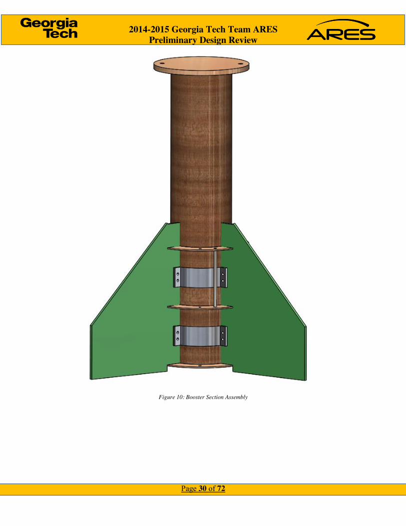
The Motor Ignition System (MIS), shown in Figure 23 will be a rack and pinion system powered
by a DC motor. The DC motor has a gear attached to the shaft which, when spun, moves the rack
up the rocket’s guide rail, into the motor cavity. The rack will have an electronic match attached
to the front which will ignite the rocket. Attached to the front of the MIS will be a steel blast plate.
The MIS will be 1.5 ft long, allowing for the rack to move up to 18 inches into the rocket. It will
be approximately 5 lbs. Attached to the front of the MIS will be a steel blast plate.
2014-2015 Georgia Tech Team ARES Preliminary Design Review
Page 49 of 72
Figure 23: Motor Igniter System
4.7 Electronics
The major components of the AGSE electronics are: 4 servo motors for the payload insertion
system, a unipolar stepper motor for the RES, and a bipolar stepper motor for the IIS. The minor
components are 2 LEDs and a button to start and stop the program. An Arduino based system will
be used to control the components because of its easy-to-use hardware and software. Specifically,
an Arduino Uno-R3 will be used as the microcontroller for the AGSE. The combination of all the
components of the AGSE occupy 13 digital I/O and 5 analog I/O. The Arduino Uno-R3 contains
14 digital I/O and 6 analog I/O. Also, the Uno-R3 has an operating voltage of 5V, which will work
more efficiently with the motors than the 3.3V that some other Arduinos use.
4.7.1 Power
The entire system will be powered by a 12V - 10.5Ah lead acid battery. This battery has enough
power to run the entire system for up to 45 minutes. Also, the Arduino Uno-R3 can run through
an external voltage of up to 20V, but the recommended maximum is 12V. This makes this battery
the ideal power source for the AGSE.
4.7.2 Microcontroller
The Arduino Uno-R3 will be connected as seen in the figure below. Each servo motor can directly
function as input to the Arduino, but stepper motors cannot because they require a different

2014-2015 Georgia Tech Team ARES Preliminary Design Review
Page 50 of 72
operating voltage from the Arduino. The two drivers shown in the figure below are used to convert
the operating voltage of the Arduino to the operating voltage of each specific stepper motor. All
the minor components can also be connected directly to the Arduino.
Each component operates at a different current; this can be seen in the table below. The
total current needed to run every system works out to be 2850 mA. Because of the 10.5 Ah from
the battery, the total time the battery can power the AGSE is 2.58 hours. This was calculated using
the formula:

2014-2015 Georgia Tech Team ARES Preliminary Design Review
Page 51 of 72
𝑇𝑖𝑚𝑒 = 𝐵𝑎𝑡𝑡𝑒𝑟𝑦 𝐶𝑎𝑝𝑎𝑐𝑖𝑡𝑦
𝐶𝑜𝑛𝑠𝑢𝑚𝑝𝑡𝑖𝑜𝑛 ∗ .7.
The .7 is used to account for all the external factors that can affect the battery life. Because not
every component is running at all times, this battery life should be significantly higher.
Arduino Component Quantity Total Operating Current
Servo Motor 4 400 mA
Unipolar Stepper Motor 1 2000 mA
Bipolar Stepper Motor 1 330 mA
LED 2 80 mA
Button 1 40 mA
Total: 2850 mA As a safety feature, the Arduino power source will be connected through a switch. In case
of any malfunction, this switch can immediately turn the Arduino off and shut down the entire
system.
4.8 Component Testing
As of the PDR, the AGSE has only one scheduled test to validate the arm-spool mechanism for
the RES. To test the RES, the team needs to construct a preliminary version of the frame and lifting
mechanism. It will include spool, wire, and motor components, as well as the lifting arm and
hinges. The first test will analyze the strength and durability of the RES by applying a 30lbs weight
in place of the rocket. We will record whether or not the RES can hold the weight stationary at
different angles of incline, including the final 85 degrees. The second test will analyze the speed
at which the rocket is raised by timing the amount of time it takes to lift a 30lbs weight to final
position. The third test determines the optimal placement for the spool in relation to the frame to
yield the greatest torque on the cable to lift the rocket.

2014-2015 Georgia Tech Team ARES Preliminary Design Review
Page 52 of 72
5 Flight Systems
5.1 Overview
Skyron’s Flight System is responsible for ensuring we reach our target apogee through the ATS,
track the location of the launch vehicle in real time, and record Skyron’s flight data. The Flight
Systems will incorporate a wide range of technologies to acquire the necessary data to activate the
recovery system and the ATS.
5.2 Success Criteria
Table 17: Mission Success Criteria for Flight Systems
Requirement Design Feature to Satisfy Requirement
Requirement Verification
Success Criteria
The vehicle shall not exceed an apogee of 5,280 ft.
Drag from the ATS system
Subscale flight test
Apogee within 1% of target
The vehicle will be tracked in real- time for location and ground recovery
GPS module will be used in the vehicle and base station
Subscale flight test
The vehicle will be located on a map after it lands for recovery
The data of the vehicle’s flight will be recorded
Sensors will save data into a memory card
Subscale flight test
The data will be recovered and readable after flight
5.3 Flight Systems Avionics Bay
The Avionics bay will house the components in charge with the recovery system, ATS system,
and data collection system. Skyron’s Avionics Bay (AB) is where all the board readings,
measurements and information is processed. To house all of the necessary avionics components
located in Table 18, the AB will be placed on a 11” x ⅛” vertical plywood board attached
perpendicularly to a G10 Fiberglass 5in Diameter hatch (Figure 25 ). This slot-vertical board hatch
assembly will then be screwed in place, using standard issue screws with ⅛” diameter, to an inner
body tube. The goal of the new dual slot feature with screws is to improve overall hatch security
during flight (Figure 24).

2014-2015 Georgia Tech Team ARES Preliminary Design Review
Page 53 of 72
Table 18: Avionics Components
Part Function
Stratologger SL100 Altimeter - used to receive and record altitude
MMA8452Q Accelerometer - used to receive and record acceleration
mbed LPC 1768 Microcontroller - used to receive sensor data to compute and control the ATS system
Eggfinder TX/RX Module GPS module - used to track the rocket in real time
9V Alkaline Batteries Used to power all Avionics components
3.7V Lithium-Polymer Batteries
High discharge batteries used for the solenoids
Figure 25: Avionics Bay in an Open Configuration Figure 24: Avionics Bay in a Closed Configuration

2014-2015 Georgia Tech Team ARES Preliminary Design Review
Page 54 of 72
5.4 Altimeters
We will be using two StratologgerCF altimeters that record data at a rate of 20 samples per second
and store it for later use. They also include a Data I/O connector which allows real-time altimeter
data to be sent to the onboard flight computer. Table 19 lists the different ports of StratologgerCF
and briefly describes the functionality of each.
Figure 26: StratologgerCF
Table 19: Stratologger Port Details
Port Name Description
A Battery Connect a 9V battery here
B Power Switch Connect a power switch here
C Main Ejection Output Connect to match for deployment
D Drogue Ejection Output Connect to match for deployment
E Data I/O Connector Connect to flight computer for real-time data transfer
F Beeper Audibly reports setting via a series of beeps
G Preset Program Button Not used

2014-2015 Georgia Tech Team ARES Preliminary Design Review
Page 55 of 72
These altimeters are functional up to 100,000 feet and deploy both main and drogue chutes. Figure
27: Electrical Schematic of Altimeter System represents the electrical process by which both the
main and drogue parachutes are deployed.
Figure 27: Electrical Schematic of Altimeter System
5.5 Apogee Targeting System Electronics
Two altimeters and one accelerometer will be the only sensors used to feed information to the
controller in order to store the information, and use it to ensure it will reach apogee. The heart of
the avionics will be the microcontroller. We will use the MBED NXP LPC1768. The altimeters
will send data serially to the MBED while the accelerometers will send data through I2C ports.
The MBED will run computations to store correct values and use those values to make flight
Figure 28: EagleCAD of main components

2014-2015 Georgia Tech Team ARES Preliminary Design Review
Page 56 of 72
adjustments. The connections of the avionics section, along with the separate GPS tracker, are
shown in the simplified diagram of Figure 28. Finally, the schematic with the main components
are shown in Figure 29.
5.6 Component Testing
To test the solenoids used in the Apogee Targeting System, we designed a simple force test to see
how much force the solenoid could generate. The solenoid was tested with how much weight (a
container with a fixed amount of water) it could pull/push in a vertical position. The force was
measured by finding the maximum amount of water that the solenoid could lift at each
displacement value The following graph illustrates the result of the test.
Figure 29: Overall Schematic of Flight Systems

2014-2015 Georgia Tech Team ARES Preliminary Design Review
Page 57 of 72
This graph shows the results of an experiment to test an individual solenoid’s force rating when
powered by a 50V source and a 33V source. The x-axis represents the displacement of the starting
position of the solenoid and the y-axis measures the resulting force. The general of the graph is
that the lifting power of the solenoid increases exponentially as the starting displacement increases.
5.7 GPS
The GPS will be the telemetry system’s most important sensor. We will use an Eggfinder GPS
tracker to send NMEA data to stream the rocket’s position as it launches and lands. The module
transmits data in the 900 MHz license-free ISM band at 100mW. The module sends packets in
9600 baud, 8 bits, and no parity. The module will be in a separate compartment within the avionics
bay. It will be shielded by placing aluminum sheet between the GPS tracker and the rest of the
compartments.
5.8 Power
The rocket’s avionics bay will be powered by 9V batteries for the microcontroller, Stratologgers,
and GPS each having their own 9V source. The solenoid ATS be powered separately by a 50V
source comprised of either 9V or high power Li-Po batteries. Here are some considerations for
each battery type:
Table 20: Different Battery Configurations
Battery Total Voltage
Number Weight Max discharge
Volume Pros

2014-2015 Georgia Tech Team ARES Preliminary Design Review
Page 58 of 72
9V 56 6 320g 500 mA 117.17 cm3 Easy Assembly
Li-Po (3.7V)
51.8 14 252g 10 A 167.09 cm3 Rechargeable, Customizable Design

2014-2015 Georgia Tech Team ARES Preliminary Design Review
Page 59 of 72
6 Safety
6.1 Overview
Team A.R.E.S. is dedicated to maintaining safe operating conditions for all team members and
anyone involved in competition activities. Under the tutelage of the Safety Officer, Stephen Kim,
Team A.R.E.S. will undergo rigorous safety briefings to ensure the integrity and safety of the entire
team and equipment is unchanged. During manufacturing, fabrication, and testing of rocket vehicle
and AGSE components, it is important to identify the hazards of your environment, and how
following safety procedures and protocols can prevent accident and injury to oneself or damage to
competition hardware. When working with construction equipment, Team A.R.E.S. members are
instructed to work in minimum team sizes of two. This ensures that one team member would be
available to provide immediate assistance or quickly get help should an incident occur while using
the equipment. The Invention Studio, where team members use the necessary equipment for
manufacturing and fabrication, is equipped with first aid kits, fire extinguishers, safety glasses,
and expert supervision for the use of all equipment. During physical testing of the rocket structure,
and during ejection charge testing, team members will wear safety glasses, have a first aid kit and
fire extinguisher on hand, and have licensed safety officials present. In order to use the machines,
all team members have been briefed on the proper protocols and procedures of using the lab
machines. Risk identification and mitigation techniques are used to assess the dangers of tools and
activities to personnel, and how they may create safe operating conditions. To that end, Table XX
lists the procedure to identify what hazards and risks may exist and how to minimize the chances
of occurrence.
Step Name Step Definition
1. Hazard Identification
Team will collectively brainstorm to identify any possible hazards that the team may encounter.
2. Risk and Hazard Assessment
Team will determine the severity and probability of consequences in case the hazard were to be encountered. How to approach each
hazard will also be reviewed.

2014-2015 Georgia Tech Team ARES Preliminary Design Review
Page 60 of 72
3. Risk Control and Elimination
After the hazard has been identified and assessed, a plan will be put in place to ensure the hazard will not occur.
4. Reviewing Assessments
The entire process will be repeated for any new hazards or existing hazard that needs to be updated.
Table XX lists the hazards, risks, and mitigations that may be experienced by the team.
Hazard Severity Likelihood Mitigation & Control
Batteries Explode
Burns, skin and eye irritation
Low Wear safety glasses and gloves when handling. Make sure no shorts exist in
circuits using batteries. If battery gets too hot, stop its use and disconnect it from any
circuits.
Black Powder Explosions, burns, skin and eye irritation
Medium Wear safety glasses, gloves when handling black powder. Be careful when pouring black powder. Operate in a static-free
environment
Dremel Cuts and scrapes Medium Only operate tools with supervision of teammates. Use tools in appropriate
manner. Wear safety glasses to prevent debris from getting into eyes.
Power Tools Cuts, punctures, and scrapes
Medium Only operate power tools with supervision of teammates. Use tools in appropriate manner. Wear safety glasses to prevent
debris from getting into eyes.
Epoxy/Glue Toxic fumes, skin and eye
irritation
High Wear gloves, nitrile for epoxy, face masks, and safety glasses. Work in well ventilated
area.
Exacto/Craft Knives
Cuts, serious/fatal
injury
Medium Only use knives with teammate supervision. Only use tools in appropriate
manner. Do not cut in the direction towards oneself.

2014-2015 Georgia Tech Team ARES Preliminary Design Review
Page 61 of 72
Fire Burns, serious/fatal
injury
Low Keep a fire extinguisher nearby. If an object becomes too hot, or does start a fire, remove power (if applicable) and be prepared to use the fire extinguisher.
Hammers Bruises, serious/fatal
injury
Medium Be aware of where you are swinging the hammer, so that it does not hit yourself,
others, or could bounce and hit someone.
Hand Saws Cuts, serious/fatal
injury
Medium Only use saws with teammate supervision. Only use tools in appropriate manner. Wear safety glasses to prevent debris from getting
in eyes.
Waterjet Cutter Cuts, serious/fatal injury, flying
debris
Low Only operate under supervision of Undergraduate/Graduate Learning
Instructors, and with other teammates. Follow proper operating procedures, wear
safety glasses.
Improper dress during
construction
Cuts, serious/fatal
injury
High Wear closed toed shoes, tie back long hair, do not wear baggy clothing.
Power Supply Electrocution, serious/fatal
injury
Medium Only operate power supply with teammate supervision. Turn off power supply when
working with circuitry.
6.2 Launch Vehicle Safety
Table XX lists the possible failure modes and respective failure prevention procedures that the Launch Vehicle may encounter during testing.
Potential Failure
Effects of Failure Failure Prevention
Apogee Targeting System (ATS)
Vehicle will not reach target altitude
Test ATS using subscale launch vehicles

2014-2015 Georgia Tech Team ARES Preliminary Design Review
Page 62 of 72
Body structure
buckling on takeoff
Launch failure, damage to launch vehicle, unable to be reused,
flying shrapnel towards personnel/crown
Test structure to withstand expected forces at launch with a factor of safety. Have proper sized couplers connecting
sections.
Drogue separation
Main parachute will deploy at high speed and may rip or
disconnect from vehicle, launch vehicle may become ballistic
Perform ground test and flight test.
Fins Fins could fall off, causing unstable flight.
Fins break or disconnect from launch vehicle, unable to be
classified as reusable
Test fin at attachment points using expected forces to ensure strength of
attachment method.
Do not have fins with sharp pointed edges, ensure parachute is large enough to minimize impact kinetic energy, test fin at attachment points using expected forces to ensure strength of attachment.
Ignition failure
Failure to launch Follow proper procedures when attaching igniter to AGSE.
Launch buttons
Launch vehicle will separate from rail, causing an unstable flight
Ensure launch rail is of proper size to accommodate the buttons, ensure buttons
slide easily into rail.
Main parachute separation
High impact velocity may damage vehicle and make it
unrecoverable, vehicle may become ballistic causing serious
injury or death
Perform ground test and flight test to ensure veracity of deployment method.
Motor failure Motor explodes, damaging launch vehicle/AGSE beyond repair
Follow NAR regulations and manufacturer’s instructions when
assembling motor. Assemble motor under supervision.
Motor retention
Motor casing falls out, lost motor case, could damage
persons/property
Test reliability of motor retention system

2014-2015 Georgia Tech Team ARES Preliminary Design Review
Page 63 of 72
Payload separation
Main parachute may not deploy correctly, higher impact velocity may damage launch vehicle, or cause personal/property damage
Perform ground and flight test to ensure veracity of deployment method
Thrust plate failure
Motor goes through vehicle, damage to vehicle, causing it to be
not reusable
Test plate and attachment method to withstand expected launch forces with a
factor of safety
6.3 AGSE Safety
Potential Failure
Effects of Failure Failure Prevention
Payload is not secured in bay
Payload will bounce inside payload bay, disrupting flight
Test various plastic clip dimensions to find best fit
RES is not stable while
raising
Rocket will not be raised, and potentially the motors will be
broken
Test subsystem, add counterweights to reduce necessary force from motor, and add more framing to increase stability
RES does not stay upright
Launch vehicle will fall unpredictably
Perfect ratchet system, ensure tension in steel cable
Electronics short circuit or are overloaded
System will lose control Fuses will protect electronics, subscale testing will prevent short circuits and
overloads
6.4 Environmental Concerns
As already mentioned in Section 6.1, the same methodology to identify and assess risks for vehicle
and payload safety will be used to identify hazards for constructing various flight and testing
components. A Material Safety Data Sheet (MSDS) is on hand for all materials used in the
construction of components, and team members have been briefed on best practices for creating a
safe workplace.

2014-2015 Georgia Tech Team ARES Preliminary Design Review
Page 64 of 72
7 Project Plan
7.1 Project Schedule
Team ARES’s project is driven by the design milestone’s set forth by the NASA SLI Program
Office. These milestones – and their dates – are listed in Table XX. Additionally, a preliminary
Gantt chart is provided in Appendix 1. It is important to note that due to the complexities of both
the launch vehicle and AGSE designs, the Gantt chart will contain only high-level activities. In
order to visualize the major tasks/steps in our design, the Team will utilize a PERT Chart/Network
Diagram. This will allow for the identification of the critical path(s), and any alternative paths.
Table XX Design Milestones set by SLI Program Office
Deadline Date
Proposal 11 SEPT
Web Presence Established 23 OCT
PDR Documentation 6 NOV
PDR Teleconference 9-20 NOV
CDR Documentation 15 JAN
CDR Teleconference 19-29 JAN
FRR Documentation 14 MAR
FRR Teleconference 17-30 MAR
Competition 13-16 APR
PLAR Documentation 29 APR
7.2 Schedule Risk
7.2.1 High Risk Tasks
Two items have been identified as “High Risk Items.” These are:
x Launch Vehicle ATS Design – failure will lead to overshooting the intended target
x Recovery System Design – failure will result in potential disaster for launch vehicle

2014-2015 Georgia Tech Team ARES Preliminary Design Review
Page 65 of 72
Table XX identifies the mitigations for these two items:
High-Risk Task Potential Impact on Project Hermes Mitigation
Launch Vehicle
ATS Design,
Fabrication, and
Testing
1) Schedule Impact
2) Budgetary Impact
3) Not qualifying for
Competition Launch
1) Ensure personnel have direct
and free access to experienced
personnel on and off the team
2) Ensure personnel have the
necessary knowledge to
effectively utilize simulation
and analysis tools
3) Ensure personnel are familiar
with relevant fabrication
techniques
Recovery
System Design,
Fabrication &
testing
1) Excessive Kinetic Energy
during landing resulting in
damage to the launch
vehicle
2) Failure to deploy drogue
and/or main parachute
resulting in a high energy
impact with the ground
destroying the launch
vehicle
1) Ensure recovery system lead
has direct and free access to
experienced personnel on and
off the team
2) Provide real time feedback of
the design decision to ensure
all recovery-related
requirements and meet with at
least a 5% margin wherever
possible
3) Ensure proper manufacturing
techniques are utilized during
the fabrication of the recovery
system
7.2.2 Low-to-Moderate Risks Tasks
The “low-to-moderate risk tasks” are considered to be those risks that pose a risk to either the
project schedule and/or project budget but little to no risk of not meeting the Mission Success
Criteria in Table XYZ. The risks and mitigations are provided in Table XX.

2014-2015 Georgia Tech Team ARES Preliminary Design Review
Page 66 of 72
Risk Task Potential Impact on Project Hermes Mitigation
Fabrication of
Launch Vehicle
Sections
1) Schedule Impact
2) Budgetary Impact
3) Not qualifying for
Competition Launch
1) Ensure personnel have direct
and free access to experienced
personnel on and off the team
2) Ensure personnel have the
necessary knowledge to
effectively utilize simulation
and analysis tools
3) Ensure personnel are familiar
with relevant fabrication
techniques
Full-Scale
Launch Vehicle
Test Flight
1) Schedule Impact
2) Budgetary Impact
3) Not qualifying for
Competition Launch
1) Ensure Launch Procedures are
established practiced prior to
any launch opportunity.
2) Have a sufficient number of
launch opportunities that are
in different geographical areas
as to minimize the effects of
weather on the number of
launch opportunities.
Flight
Computer
Fabrication/
Calibration
1) Budgetary Impact
2) Not able to collect in-flight
data
1) Ensure proper manufacturing
techniques are observed
during fabrication.
2) Ensure Manufacturing and
Fabrication Orders (MFO’s)
are sufficiently detailed for
the task.

2014-2015 Georgia Tech Team ARES Preliminary Design Review
Page 67 of 72
7.3 Critical Path
The critical path for the next section of the NASA SLI Program involves cooperation across all
four major fronts: Launch Vehicle, AGSE, Flight Systems, and Project Plan

2014-2015 Georgia Tech Team ARES Preliminary Design Review
Page 68 of 72
8 Project Budget
8.1 Funding Plan
In order to fund the 2015-2016 competition cycle, Team ARES have sought sponsorships from
academic and industry sources. The current sponsors of Team ARES and their predicted
contributions can be found in Table XX. Additionally, the Team has also received a dedicated
room in which the Team can construct and store their launch vehicle, payload, and other non-
explosive components. All explosive components (i.e. black power) are properly stored in Fire
Lockers in either the Ben T. Zinn Combustion Laboratory or the Ramblin’ Rocket Club Flammable
Safety Cabinet. Furthermore, the Georgia Tech Invention Studio will support all fabrication needs
of the Team.
Sponsor Contribution Date
2014-2015 Unused Funds $1,200 --
Georgia Space Grant Consortium $1,000 Nov 2015
Georgia Tech School of Aerospace
Engineering
(est.) $1,000 Dec 2015
Georgia Tech Student Gov’t Association (est.) $1,000 Dec 2015
Corporate Donations (est.) $2,000 Jan 2016
Orbital ATK Travel Stipend (est.) $400 Apr 2016
Total $6,600
8.2 Current Sponsors
Table XX lists the current sponsors of Team ARES and their contributions
Sponsor Contribution
Georgia Space Grant Consortium Financial Contribution for general project expenses
Advanced Circuits Manufacturing of Flight Systems throughout design
process

2014-2015 Georgia Tech Team ARES Preliminary Design Review
Page 69 of 72
8.3 Projected Project Costs
The projected project budget is approximately $5.872.38 – below the projected fundraising goal
by just over 11%. This cost was derived using the actual project costs from the 2015-2016 NASA
SLI competition cycle and a 15% margin was added to the Launch Vehicle and Flight Systems
costs during the previous project cycle. The project budget breakdown is listed numerically in
Table 21: Budget Summary and graphically in Figure 30.
Table 21: Budget Summary
Section Cost
Avionics $700.00
AGSE $808.60
Launch Vehicle $963.78
Testing $900.00
Motor $1,000.00
Operations $1,000.00
Outreach $500.00
Total Budget $5,872.38
8.4 Budget Summary
Table 22 lists the expenses as of the PDR Milestone. The summary is broken down into five (5)
main categories: Launch Vehicle, AGSE, Flight Systems, Operations, and Testing. The Launch
Vehicle and Flight Systems categories are further broken down into two (2) subcategories: Flight
Hardware and Testing. Operational expenses include: non-system specific test equipment, Team
supplies, non-system specific fabrication supplies, as well as any travel and outreach expenses.
Any system-specific equipment bought for testing is charged against that specific system.
$700.00
$808.60
$963.78
$900.00
$1,000.00
$1,000.00
$500.00
2015-2016 ARES Projected Budget Distribution
Avionics
AGSE
Launch Vehicle
Testing
Motor
Operations
Outreach
Figure 30: Budget Summary
2014-2015 Georgia Tech Team ARES Preliminary Design Review
Page 70 of 72
Table 22: Expenses as of PDR
Subsystem Amount
Launch Vehicle $0
Flight Systems $14.53
AGSE $92.69
Operations $20.00
Testing $2.50
Total $129.72
As of PDR, no purchases have been made for the Launch Vehicle, however with the Subscale
launch in two weeks, purchases will be made sooner rather than later.
9 Education Engagement Plan and Status
9.1 Overview
The goal of Georgia Tech’s outreach program is to promote interest in the Science, Technology,
Engineering, and Mathematics (STEM) fields. Team A.R.E.S. intends to conduct various outreach
programs targeting middle school Students and Educators. Team A.R.E.S. will have an outreach
request form on their webpage for Educators to request presentations or hands-on activities for
their classroom. The team plans to particularly encourage requests from schools in disadvantaged
areas of Atlanta, with the goal of encouraging students there to seek careers in STEM fields.
9.2 Atlanta Maker’s Faire
Team ARES had a booth at the Atlanta Makers Fair, a fair in which various craftsman from the
community and Georgia Tech assemble to show off their accomplishments. The intent of this
program is to give clubs, organizations, and other hobbyists the opportunity to show others their
unique creations and skills. The event is open to the entire Atlanta community and had a large
attendance this year. The Team ARES booth had a display of our various rockets, as well as a
station for children to use stomp rockets. Our booth had 45-60 middle school aged children attend
and participate in the stomp rocket activity across the two days.

2014-2015 Georgia Tech Team ARES Preliminary Design Review
Page 71 of 72
9.3 FIRST Lego League
FIRST Lego League is an engineering competition designed for middle school children in which
they build and compete with an autonomous MINDSTORMS robot. Annual competitions are held
centered on a theme exploring a real-world problem. Team A.R.E.S. plans to have a booth at the
Georgia Tech FIRST Lego League Tournament, with the goal of illustrating how the skills and
ideas utilized in the competition translate to real world applications; in particular, a rocket with
autonomous capabilities. The team also plans to help judge the tournament.
9.4 CEISMC GT
The Center for Education Integrating Science, Mathematics, and Computing (CEISMC) is a
partnership uniting the Georgia Institute of Technology with educational groups, schools,
corporations, and opinion leaders throughout the state of Georgia. Team ARES is dedicated to the
enhancement of STEM education and will look forward to partnering with CEISMC and their
events in the near future.

2014-2015 Georgia Tech Team ARES Preliminary Design Review
Page 72 of 72
10 Appendix I

ID Task Mode
Task Name Start Finish
1 NASA SL Competition Fri 8/7/15 Mon 4/18/16
2 RFP Released by NASA Fri 8/7/15 Fri 9/11/15
3 Proposal Fri 8/7/15 Fri 11/6/15
4 Team Formation Thu 8/20/15 Mon 8/24/15
5 Initial Rocket Design Thu 8/20/15 Thu 9/3/15
6 Initial AGSE Design Thu 8/20/15 Thu 9/3/15
7 Internal Proposal Review Thu 9/3/15 Fri 9/11/15
8 Proposal Submitted Fri 9/11/15 Fri 9/11/15
9 Prelimary Design Review Thu 8/20/15 Fri 11/6/15
10 Launch Vehicle Fri 9/11/15 Fri 10/30/15
11 Avionics Bay Final Design Thu 10/1/15 Thu 10/8/15
12 ATS Final Design Thu 10/1/15 Thu 10/8/15
RFP Released by NASA
Proposal
9/11
Prelimary Design Review
Launch Vehicle
E B M E B M E B MJuly August September October
Task
Split
Milestone
Summary
Project Summary
Inactive Task
Inactive Milestone
Inactive Summary
Manual Task
Duration-only
Manual Summary Rollup
Manual Summary
Start-only
Finish-only
External Tasks
External Milestone
Deadline
Progress
Manual Progress
Page 1
Project: GC 15 MK 1Date: Fri 11/6/15

ID Task Mode
Task Name Start Finish
13 Individual CAD Components Thu 10/1/15 Thu 10/8/15
14 Complete Materials List for Full Scale
Fri 10/9/15 Fri 10/16/15
15 FullScale Design Complete Sat 10/17/15 Sat 10/17/15
16 Complete Materials List for Sub Scale
Mon 10/19/15
Thu 10/22/15
17 Sub Scale Material Purchase Thu 10/22/15
Thu 10/22/15
18 AGSE Fri 9/11/15 Fri 10/30/15
19 Finalize Overall Design Fri 9/11/15 Thu 10/8/15
20 PLIS Overall Design Fri 9/11/15 Tue 10/6/15
21 REM Overall Design Fri 9/11/15 Tue 10/6/15
22 MIS Overall Design Fri 9/11/15 Tue 10/6/15
23 AGSE Internal Design Review Fri 10/9/15 Fri 10/9/15
24 Electronic Schematics Fri 9/11/15 Thu 10/8/15
AGSE
10/9
E B M E B M E B MJuly August September October
Task
Split
Milestone
Summary
Project Summary
Inactive Task
Inactive Milestone
Inactive Summary
Manual Task
Duration-only
Manual Summary Rollup
Manual Summary
Start-only
Finish-only
External Tasks
External Milestone
Deadline
Progress
Manual Progress
Page 2
Project: GC 15 MK 1Date: Fri 11/6/15

ID Task Mode
Task Name Start Finish
25 Complete Materials List Fri 10/9/15 Tue 10/13/15
26 SubSystem Testing Planning Fri 10/9/15 Thu 10/29/15
27 Prelimaniry PLIS Construction Thu 10/15/15
Thu 10/29/15
28 Flight Systems Fri 9/11/15 Thu 10/29/15
34 PDR Review Thu 10/29/15
Thu 11/5/15
35 PDR Submitted Fri 11/6/15 Fri 11/6/15
36 Critical Design Review Mon 11/9/15
Fri 1/15/16
37 Flight Systems Mon 11/9/15
Mon 11/9/15
38 Full Design Implementation Mon 11/9/15
Mon 11/23/15
39 Full Component Testing Mon 11/23/15
Mon 11/30/15
40 Recovery System Test Sat 11/28/15 Sat 11/28/15
41 Launch Vehicle Mon 11/9/15
Fri 1/15/16
Flight Systems
11/6
Critical Design Review
Flight Systems
11/28
E B M E B M E B MJuly August September October
Task
Split
Milestone
Summary
Project Summary
Inactive Task
Inactive Milestone
Inactive Summary
Manual Task
Duration-only
Manual Summary Rollup
Manual Summary
Start-only
Finish-only
External Tasks
External Milestone
Deadline
Progress
Manual Progress
Page 3
Project: GC 15 MK 1Date: Fri 11/6/15

ID Task Mode
Task Name Start Finish
42 Final Design of Launch Vehicle Mon 11/9/15
Sat 12/12/15
43 ATS Static Ground Testing Mon 11/9/15
Fri 11/13/15
44 ATS Wind Tunnel Testing Sun 11/22/15
Sat 12/12/15
45 Structural Testing Mon 11/30/15
Sat 12/12/15
46 Full Scale Material Purchase Mon 11/23/15
Mon 11/30/15
47 Full Scale Material Purchase Mon 11/16/15
Fri 11/20/15
48 Beginning of Full Scale Construction
Mon 1/11/16
Fri 1/15/16
49 Flight Readiness Review Thu 1/14/16 Mon 3/14/16
51 Avionics Bay Refinement Sat 1/16/16 Thu 3/3/16
52 Control System for ATS Refinement
Sat 1/16/16 Thu 3/3/16
53 Launch Vehicle Mon 1/18/16
Thu 3/3/16
54 Final Launch Vehicle Construction
Mon 1/18/16
Fri 2/19/16
E B M E B M E B MJuly August September October
Task
Split
Milestone
Summary
Project Summary
Inactive Task
Inactive Milestone
Inactive Summary
Manual Task
Duration-only
Manual Summary Rollup
Manual Summary
Start-only
Finish-only
External Tasks
External Milestone
Deadline
Progress
Manual Progress
Page 4
Project: GC 15 MK 1Date: Fri 11/6/15

ID Task Mode
Task Name Start Finish
55 Full Scale Recovery System Launch
Sat 2/13/16 Sat 2/13/16
56 Full Scale Test Launch Sat 2/20/16 Sat 2/20/16
57 AGSE Mon 1/18/16
Thu 3/3/16
58 Finalize Construction of Entire AGSE
E B M E B M E B MJuly August September October
Task
Split
Milestone
Summary
Project Summary
Inactive Task
Inactive Milestone
Inactive Summary
Manual Task
Duration-only
Manual Summary Rollup
Manual Summary
Start-only
Finish-only
External Tasks
External Milestone
Deadline
Progress
Manual Progress
Page 5
Project: GC 15 MK 1Date: Fri 11/6/15
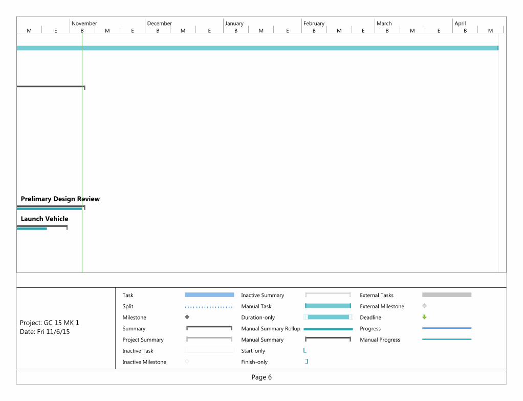
RFP Released by NASA
Proposal
9/11
Prelimary Design Review
Launch Vehicle
M E B M E B M E B M E B M E B M E B M EOctober November December January February March April
Task
Split
Milestone
Summary
Project Summary
Inactive Task
Inactive Milestone
Inactive Summary
Manual Task
Duration-only
Manual Summary Rollup
Manual Summary
Start-only
Finish-only
External Tasks
External Milestone
Deadline
Progress
Manual Progress
Page 6
Project: GC 15 MK 1Date: Fri 11/6/15

AGSE
10/9
M E B M E B M E B M E B M E B M E B M EOctober November December January February March April
Task
Split
Milestone
Summary
Project Summary
Inactive Task
Inactive Milestone
Inactive Summary
Manual Task
Duration-only
Manual Summary Rollup
Manual Summary
Start-only
Finish-only
External Tasks
External Milestone
Deadline
Progress
Manual Progress
Page 7
Project: GC 15 MK 1Date: Fri 11/6/15
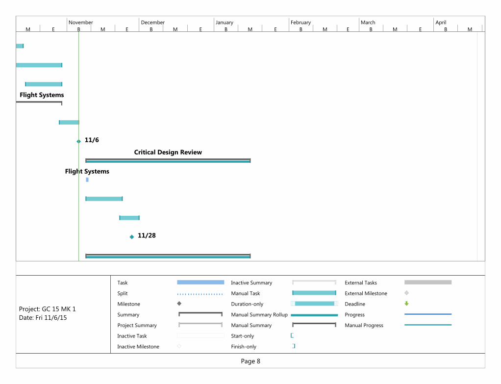
Flight Systems
11/6
Critical Design Review
Flight Systems
11/28
M E B M E B M E B M E B M E B M E B M EOctober November December January February March April
Task
Split
Milestone
Summary
Project Summary
Inactive Task
Inactive Milestone
Inactive Summary
Manual Task
Duration-only
Manual Summary Rollup
Manual Summary
Start-only
Finish-only
External Tasks
External Milestone
Deadline
Progress
Manual Progress
Page 8
Project: GC 15 MK 1Date: Fri 11/6/15

Flight Readiness Review
M E B M E B M E B M E B M E B M E B M EOctober November December January February March April
Task
Split
Milestone
Summary
Project Summary
Inactive Task
Inactive Milestone
Inactive Summary
Manual Task
Duration-only
Manual Summary Rollup
Manual Summary
Start-only
Finish-only
External Tasks
External Milestone
Deadline
Progress
Manual Progress
Page 9
Project: GC 15 MK 1Date: Fri 11/6/15

2/13
2/20
M E B M E B M E B M E B M E B M E B M EOctober November December January February March April
Task
Split
Milestone
Summary
Project Summary
Inactive Task
Inactive Milestone
Inactive Summary
Manual Task
Duration-only
Manual Summary Rollup
Manual Summary
Start-only
Finish-only
External Tasks
External Milestone
Deadline
Progress
Manual Progress
Page 10
Project: GC 15 MK 1Date: Fri 11/6/15