Embed Size (px)
Citation preview

Equipment Safety aspects of the SRF Cavity/He Vessel/Tuner system.Role of the Cavity Tuner to support/deliver equipment safety demands.Modification of the LCLS II pCM Tuner
Yuriy PischalnikovMarch 26, 2015

LCLS II pCM Tuner_V1
2

Outline
Review of the Cavity/He Vessel/Tuner system safety (equipment)
Table with anticipated steps during assembly and operation of the CM
* SRF Cavity safety* Tuner active components safety
Modifications introduced into the design the LCLS II Tuner_V1 for pCM (Tuner_V2)
Summary
3

I.Gonin/T.KhabiboulineCOMSOL simulation of the cavity/He Vessel/Tuner (brackets) system
4

TEM
PERA
TURE
PRO
TECT
ION
The step during cavity assembly or operations
Insu
late
d Va
cuum
, bar
abs
Cavi
ty B
eam
line,
ba
r abs
Heliu
m V
esse
l, ba
r abs
Forces on cavity flange
with absolutely restrained cavity, kN
Cavity lengthwill changes if
flange non-restrained,
mm
Tcav
=300
K REST
RAIN
BRA
CKET
S
0 Cavity is relaxed after HV welding 1 1 1 0 0
1 Cavity/He Vessel Leak Check at MP9 1 1 0 -2.6 -0.6
2 Cavity/He Vessel Pressure test at MP9 1 1 3.3 6.0 1.4
3 Cavity/He Vessel Leak Check in CM/HTS 1 0 0 -3.8 -0.8
4 Cavity/He Vessel leak check in Clean Room 1 0 1 -1.2 -0.25
TUN
ER IN
STAL
LED
ON
CAV
ITY
5 He Vessel pressure test in CM 1 0 3.3 4.9 1.1
6 Start of cooling down CM 0 0 1.5 3.9 0.8
7Linac maintenance (e.g.,
tuner or interconnect access)
1 0 1.4 0 0
8a Tuner access and disconnect (e.g., replace piezo), what is max cryo
system pressure
1 0 0 -3.8 -0.8
8b 1 0 2.5 2.7 0.6
5K 9 End of cooling down 0 0 1.5 3.9 0.8
2K 10 Operating condition 0 0.03 0 0 0
5K 11Worst case cold loss of vacuum accident. Will
piezo and tuner survive?0 0 4 10.4 2.2
Highlighted steps when cavity at 300K will go beyond elastic deformation if do not protected with tuner/safety brackets system.
Impact on the Cavity/He Vessel/Tuner system for various pressure conditions during anticipated steps of assembly and operation of the CM.
Requirements: |∆XT=300K| < 0.6mm
Accident at cold CM Impact on the Tuner/piezo

Safety (restrain) Brackets for Cavity/He Vessel system(serve at steps 0,1,2,3,4 )cavity flange split ring &brackets need to be installed as soon as cavity welded into He Vessel.
Brackets (& flange ring) will remain as part of the system during pressure/leak check; during transportation; at processing facility; inside Clean Room; during test at VTS (and occasional test at HTS /without Tuner-High Q0 test).
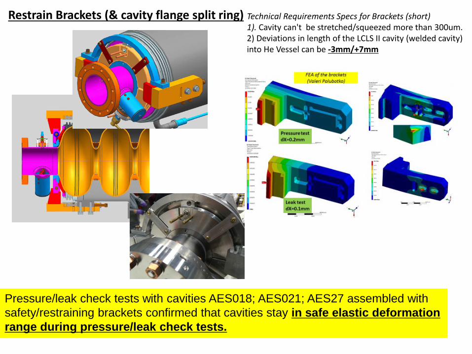
Restrain Brackets (& cavity flange split ring) Technical Requirements Specs for Brackets (short) 1). Cavity can't be stretched/squeezed more than 300um.2) Deviations in length of the LCLS II cavity (welded cavity) into He Vessel can be -3mm/+7mm
Pressure/leak check tests with cavities AES018; AES021; AES27 assembled with safety/restraining brackets confirmed that cavities stay in safe elastic deformation range during pressure/leak check tests.

Role of the Safety Restrain Brackets (and Arc) to protect cavity during transportation /assemblyAnalysis & COMSOL simulation performed by Gonin/Khabibouline
Fv=g*ρ corresponding to Earth gravity
Total Displacement
Cavity Support Arc was designed to protect Helium Vessel bellows against transverse acceleration
Cavity limit for transverse acceleration is 3g Bellows limit for transverse acceleration is 23g Detailed analysis demonstrated that cavity is weaker
than bellows in term of transverse acceleration Support Arc not designed to protect the cavity
against axial acceleration (brackets OR tuner will protect cavity)
Cavity displacement and deformation due to gravity is small and not depend on Support Arc installation
Therefore recommended to remove Support Arc from Dressed Cavity assemblySupport Arc will be used only to support cavity inside Clean Room assembly… Arc will be reusable part (made from 304)…Removal of the Arc will increase range of the Slow Tuner
Support Arc
8

LCLS II pCM Tuner_V2 (Modification of theTuner_V1) - (1)- Safety Rod
– to protect cavity from excessive stretching during leak check test inside CM
Tuner_V1 designed to tune cavity by “pushing” on the cavity… no any mechanism to prevent cavity from excessive deformation by forces directed inside cavity volume… Step#3
F=3.8kN
Tuner_V1(no safety rod)
Tuner_V2(with safety rod)
9

LCLS II pCM Tuner_V2 (Modification of theTuner_V1) –Safety Rod (1) & Piezo Preload tuning mechanism (2)
Small Tuner modification (removing Support Arc, modifying edges of arms) led to increasing tuning range to 1.7mm (on the cavity flange)∆F will increase 450kHz 580kHz
Screw on the Top&Bottom main levers will help to adjust uniform preload of the Top&Bottom piezo-stacks.
10

LCLS II pCM Tuner_V2 (Modification of theTuner_V1) –Stepper Motor Limit switches(3) & washers to avoid loosening screws(4)
Equipment safetyLimit switches to prevent hitting “hard stops”.When tuner arm hit “hard stops” forces applied to traveling nut can reach 2-4kN (much above 1.3kN design forces)… traveling nut will be damaged ---experience from first cold test of the Tuner
In the XFEL design “hard stops” will damage harmonic drive…
washers to avoid loosening screws(4)
11

Piezostack safety in case of vacuum accident (Step #11)(equipment safety)
Encapsulated piezo designed and manufactured by Physik Instrumente (PI) per FNAL specifications.Blocking Forces 3,8kN
Designated Test of “cold-80K” piezo “6kN survivor” test
Fixture with piezo-capsule was cool-down inside LN2,installed into INSTRON and measured C vs Forces
Piezo Survived 6kN test
12

Summary
FNAL LCLS II team reviewed equipment safety aspects of the Cavity/He Vessel/Tuner (C/HV/T) system.
As a result of the review special table was generated. Table presented anticipated steps of assembly and operation of the CM and for various pressure conditions.
Unsafe steps (when any part of C/HV/T system can compromised) were identified.
Tuner design was modified to address uncovered deficiency.
Designated tests were conducted to confirm safe operation of the components of C/HV/T system
13