Embed Size (px)
Citation preview

16 JANUARY 2018 Mınıng engıneerıng www.miningengineeringmagazine.com
Equipment
The Coeur d’Alene mining district in northern Idaho was first discovered more
than 130 years ago and has been the most prolific silver producer in the United States. The Lucky Friday Mine of Hecla Mining Co. (Fig. 1) is the oldest (76 years) and deepest mine in the district, producing approximately 725 t/day (800 stpd) from narrow, vertical lead-zinc-silver veins. Cut-and-fill stoping is currently employed at
depths to about 2.3 km (7,500 ft) below ground surface, making it one of the three deepest mines in the western hemisphere. The #4 Shaft, a winze collared at approximately 1.8 km (5,900 ft) below surface and extending to a depth of nearly 2.9 km (9,600 ft), was recently completed
to exploit the high-grade 30 Vein, whose resource has been identified to at least 3 km (9,700 ft) in depth.
As with other deep mines worldwide, a number of challenging engineering issues occur, including: high in situ rock stress, squeezing ground, seismicity, high in situ rock temperature that requires refrigeration, diesel equipment that generates diesel particulate matter
(DPM) requiring high ventilation airflow rates and long travel times for worker transport to mining areas.
This article describes the methods that Hecla Mining Co. has employed during the past 50 years to combat these issues, with emphasis on the current efforts to implement continuous, mechanical mining with automated or tele-remote operation and to introduce electric and battery-powered equipment to minimize refrigeration and ventilation requirements for the removal of DPMs.
Geology and in situ stressThe host rock mass is an extremely thick
sedimentary sequence (the Belt Series) that has been tilted vertically by mountain building. The rock mass in the current section of the mine consists of weak, heavily foliated argillites and stronger, bedded silty-argillites termed siltite. The vertical veins (80° to 85° dip) are parallel to the foliation with an approximate width of around 3 m (10 ft). There are two regional, vertical faults that parallel the vein; one forming the hangingwall of the orebody and one approximately 90 m (300 ft) in the footwall. Additionally, there are several thin, rough north-dipping faults that occur in the footwall of the vein which terminate on the major vertical faults.
Both the argillite and vein package rock have moderate strength, with uniaxial compressive strength averaging about 100 MPa (14,700 psi with a range from about 70 to 125 MPa), and are moderately abrasive, with CERCHAR abrasivity index of 2 to 3. The major in situ stress is horizontal and oriented in a northwest direction with magnitude about 1.5 times the vertical stress. Consequently, the Lucky Friday stress magnitude at depth is analogous to significantly deeper South African gold operations.
Evolution of the mining methodOverhand cut and fill with hydraulic fill.The primary mining method employed at
the Lucky Friday Mine since its inception has been cut and fill. Prior to the 1980s, overhand cut and fill with hydraulic sand backfill was used. Horizontal production levels were driven every 60 m (200 ft) vertically from the shaft, and five or more slusher stopes established on each level. As the horizontal line of stopes
Mobile mechanical vein miner; New machine developed for Lucky Friday Mineby Clayr Alexander, Mark Board, Wes Johnson and Mikael Ramström
Clayr Alexander and Wes Johnson, members SME, are vice president- general manager and chief engi-neer, Hecla Ltd, Lucky Friday Mine, Mullan, ID, Mark Board, member SME, is vice president, technical services, Hecla Ltd, Coeur d’Alene, ID, and Mikael Ramström, is direc-tor - global strategic partners and alliances, with Atlas Copco, Örebro, Sweden, email [email protected].
The Lucky Friday Mine is located in the Northern Idaho Panhandle near the Montana state line.
Figure 1

www.miningengineeringmagazine.com Mınıng engıneerıng JANUARY 2018 17
Equipment
progressed upward toward the previously mined level above, a sill pillar of diminishing height was created. When this pillar was reduced in height to less than around 15 m (50 ft), pillar bursting would begin and continue until the pillar yielded. To minimize the size and occurrence of the seismicity, the advance line of the stopes was altered to a staggered pyramid or stair-step shape in the mid-1970s (Board and Crouch, 1977). This change in geometry, though simple, tended to minimize the amount of highly stressed pillar, reduced the overall energy release rate and tended to shunt stresses to the abutments.
Underhand mining with paste fill. Although the overhand stope advance geometry change reduced the magnitude of seismic events, it did not totally prevent them, since pillars were still created. A study focused on reducing the seismic hazard was conducted in the late 1970s, with a recommendation to convert the method to a mechanized underhand approach (Board and Voegele, 1981). In the early 1980s, the mining method was changed accordingly, utilizing an engineered cemented paste fill back. The method, termed the Lucky Friday Underhand Longwall (LFUL) converted the stope access from captive in-vein raises to a series of footwall spiral ramps with slotting to the vein. The original objective of the method was to create a downward-advancing longwall that would eliminate pillars and continuously shunt the stresses to abutments in advance of mining. This method is still currently in use and has been successful in reducing seismic occurrence and event magnitude through minimizing the creation of pillars and reducing in the exposure of miners to the stope face area. The engineered cemented paste fill back has been very successful in improving stope ground conditions. In the mid-1990s, a major new vein (the 30 Vein) was discovered at depth beneath the historic Gold Hunter mine — about 1.6 km (1 mile) northwest of the Lucky Friday Mine. Whereas the host rock mass at the Lucky Friday was a brittle and strong siliceous quartzite (the Revett formation), the 30 Vein is located in the weaker and heavily foliated argillite (the Wallace formation) described previously. The 30 Vein is located approximately 1.6 km (1 mile) north of the Lucky Friday Vein.
Underhand mining using teleremote continuous mechanical cutting. All mining activity was transferred from the Lucky Friday vein to the 30 Vein (and associated parallel veins) in the late 1990s, with access to the 30 Vein via horizontal haulage drives from the Silver Shaft at the 4900 and 5900 levels. The shallower depth and lithologic change to a weaker, more deformable rock mass resulted in a significant reduction in seismicity. As mining continued with depth, seismicity occurred, primarily at some distance from the vein as the result of slip on the north-dipping fault structures. Currently, mining has progressed down-dip to approximately the 6300 Level, 2.2 km (7,300 ft) below surface (Fig. 2). Exploration drilling below the advancing mining front has identified a prominent widening 30 Vein resource with increasing silver and base metal grades. The current reserve has been identified to the 7600 level and has been intercepted below the 8000 level. To exploit this deep resource, a decision was made in 2009 to begin construction on a winze from the 4760 Level to the 8620 Level (2.9 km or 9,590 ft) depth. This shaft was completed in January 2017 (Sturgis, et al., 2017).
To ensure the viability of mining the 30 Vein to such great depth, a revision of the current
Cross section view of 30 Vein mining showing north wall LFUL develop-ment including the #4 shaft completed in 2017.
Figure 2
Author’s Note:AtlasCopco’sMiningandRockExcavationTechniquebusinessareaisinthemidstofchangingitsnametoEpiroc,inpreparationforasplitfromtheparentcom-panyinmid-2018.ThisarticlewillthereforerefertobothEpirocandAtlasCopco.

18 JANUARY 2018 Mınıng engıneerıng www.miningengineeringmagazine.com
Equipment
underhand mining method is necessary to minimize both seismic potential and exposure of workers to increased heat and diesel particulates. An internal Hecla study was conducted to initially identify overall criteria for the method and to then develop a mining concept. The criteria identified were as follows:
• Minimize seismic potential by elimination of pillars using a true underhand longwall to bottom-slice the 30 Vein, and, through use of an incremental, continuous mechanical mining method that eliminates in-stope blasting that may trigger remote fault-slip movement.
• Eliminate diesel particulates and reduce heat rejection to the ventilation by implementing battery and electric equipment to the extent possible. Ultimately, this will minimize refrigeration requirements and increasing ventilation demand.
• Remove workers from in-stope conditions to the extent possible by using state-of-the-art teleremote and autonomous operations.
Based on these criteria, Hecla entered into discussions with numerous equipment OEM’s for development of a specially purposed mechanical mobile miner that could cut the relatively weak and moderately abrasive vertical veins. Mechanical cutting is facilitated by the relatively uniform width of the 30 Vein and the predictable orientation and continuity (no offsets) of the vein over its 760 m (2,500 ft) strike length. Atlas Copco was selected as a partner in this project due to its long-term development of steel disc-based tunnel boring machine (TBM) Mobile Miner technology (including a similar unit in current testing)
and its willingness to share in development engineering and testing costs. A set of design and operational criteria were developed for the mobile miner based on:
• Advance rate (ft/day/machine).• Mining width and height. • Maneuverability (turning radius) and
negotiable grade.• Operation within the constraints of the
current underhand mining system with engineered paste-fill roof.
• Teleremote (nontethered) operation and automated face-cutting operations.
• Onboard bolter for wall bolting and meshing (roof presupported) with goal of eventual automation.
• Wall collision detection and guidance assist.
• High definition cameras for face viewing.
Confirmation of the cutability of the 30 Vein package, which consists of sulfide ore and gangue material of siderite (iron carbonate) and argillite was achieved via linear cutter testing on large blocks of vein package material at the Earth Mechanics Institute of the Colorado School of Mines (CSM, 2017). This testing, using standard 43 cm (17 in.) steel disc cutters, demonstrated successful cutting and spalling of rock chips using 75 to 100 mm (3 to 4 in.) cutter spacing and moderate applied cutter forces (Fig. 3). Due to the moderate abrasivity of the vein, cutter wear is expected to be low.
An approximate one-and-a-half year design program was initiated in 2015, culminating in completion of the design in early 2018 with manufacturing scheduled to be completed by early 2019. Currently, it is estimated that a five-month testing phase will be conducted in a test mine at the manufacturer’s site, followed by shipment, reassembly, commissioning and proof-of-concept at the Lucky Friday Mine starting in late 2019 or early 2020.
Hecla Mobile Miner descriptionThe Hecla Mobile Miner is a machine for
mechanical rock excavation of tunnels in hard rock. It uses standard steel disc ring rolling cutters on the circumference of a wheel, or cutterhead, to crack and fracture the rock so it can be transported via a conveyor to the back of the machine. The cutterhead is suspended on a boom and the rotating axis is horizontal so the cutters are rolling with vertical kerfs. The mobile miner is a partial-face machine, which requires the cutterhead to be repositioned to be
Linear cutter testing of 30 Vein blocks at Colorado School of Mines Earth Mechanics Institute — Chip formation between cutter tracks.
Figure 3

www.miningengineeringmagazine.com Mınıng engıneerıng JANUARY 2018 19
Equipment
able to excavate the entire tunnel face.Its main benefits are:
• High mobility — multi face development.• High productivity compared to drill and
blast.• No need for blasting and therefore no need
for charging, ventilating and scaling.• No secondary cracks in rock due to
blasting which improves ground support application and stability.
The following are operational requirements and specifications developed for the Mobile Miner:
GeometryTunnel Width: 3 to 4.5 m (10 to 14.7 ft) Height: 3.6 to 4.5 m (11.8 to 14.7 ft) Incline: ±20 percentTurning Horizontal radius: 13 m (42.5 ft) at 4.5 m (14/7 ft) width Vertical radius: 50 m (164 ft)Machine size Width: <2.5 m (8.2 ft) Height: 3.5 m (11.4 ft) Length: ~20 m (65 ft) Transport size: 1.8 m x 1.8 m (6 x 6 ft) Ground clearance: nom. 200 mm (7.8 in.)
ElectricCutting Voltage: 13.8 kV/60 Hz, 4160v/60 Hz Power: 2 x 350 kW (470 hp) Cable: 50 mm² Cable reel: yes, 150 m (492 ft)
Motor control centerCutting Type: VFD Location: Remote Communication: Ethernet Safety certification: UL
Step-down transformer: yes, from 13.8 kVTramming Voltage: 480V/60 Hz Power: 95 kW (127 hp) Inlet socket: 70 mm² Cable reel: no
Cutting systemCutterhead standard Number of cutters: 32 Spacing: nom. 86 mm (3.4 in.) Cutter per kerf: 2 Type of cutter: 43 cm (17 in.) steel ringCutterhead dimensions Diameter: Ø3.5 m (11.8 ft) Width: 1.2 m (4 ft)Drive system Rotation Speed: 12 rpm Drive train: hydraulic radial piston Power: 500 kW (670 hp) hydraulicCutterhead kinematics Boom slew: ±25° Boom lift: 26.5° up, 6.5° down Total stroke: 840 mm (33 in.) Cutting stroke: 650 mm (26 in.)
General arrangement. The mobile miner consists of two major parts; the rear power unit and the front miner (Fig. 4). The miner part incorporates the cutterhead and everything needed to excavate rock while the power module that contains all the motors, pumps, ground support and control systems. Each unit is roughly 10 m (30 ft) in length. The two parts are connected by an articulation joint to improve negotiation of tight corners as well as minimize vibration at the operator’s cab. The miner has two track units and the power unit one twin track that can be controlled separately. To obtain better steering control of the power unit, the track is mounted on a slewing bearing allowing the trailer to swing sideways when the tracks are slewed 90°.
Miner. The miner part consists of the thrust
Side view of the mobile miner showing major machine components.
Figure 4
20 JANUARY 2018 Mınıng engıneerıng www.miningengineeringmagazine.com
Equipment
module, with cutterhead and front frame. During cutting, the thrust module moves the cutterhead in a forward, up-down or slewing motion, while the front frame remains gripped to the excavation.
Thrust module. The thrust module consists of the thrust frame that holds the link, slew cylinders, lift cylinder, attachment for the thrust cylinder and hoses that feed the cutterhead motor. Its main purpose is to provide a reaction for the forces produced in the cutterhead and link them into the main frame. The forces are routed to the main frame via two guide tubes in front and two tubes in the aft portion of the thrust frame. Bearings on guide tubes are cylindrical bronze bushings sealed with hydraulic cylinder wiper rings and lubricated by grease. Thrust is provided by one cylinder attached between the main module and the thrust module.
Front frame. The front frame fixes the machine to the excavation to make it a stable platform for the thrust frame. It consists of a main frame, track frames, two lower jacks and 10 upper stingers. The front frame also carries the front apron with the conveyor, two dust collectors and a dust shield. The frame is a steel plate, central box frame designed to take and transfer all loads from stingers and the thrust frame. At the rear end of the frame is the articulation joint where the power module
is attached. There is one track drive on each side of the front frame; each drive is driven independently of the other to make steering possible. The dust shield is mounted on the front wall between the front frame and the moving thrust module. The dust shield, when inflated, creates a seal against the stope back and walls, making the dust suppression system more efficient. During cutting, the upper roof stingers transfer applied forces to the lowered jacks and tracks to accommodate the lateral loads applied to the cutter wheel.
Cutterhead. The cutters are attached to four segments bolted to the
drive unit. The cutterhead drive units consist of a fixed inner part, which holds the bearing and the hydraulic motor. A spline shaft transfers the torque from the motor to the rotating outer part without any gearbox. This solution drastically reduces the complexity of the drive unit, making it more robust. The bearing between the fixed and rotating part consists of a cylindrical roller bearing for radial loads and two cylindrical roller thrust bearings for the axial and bending loads. Multiple seals protect the bearings. The outermost seal is replaceable without dismantling the drive unit. The seals are pressurized and lubricated by a combination of compressed air and lubrication oil. The motor is a radial piston hydraulic motor with hollow spline shaft and can be rotated in either direction. A cross-over valve is used to protect the motor from peak pressures. A proximity sensor measures the speed of the output shaft.
Bearing lube system. The cutterhead main bearing runs in an oil bath — the bearing cavity is partially filled with lubrication oil. The lubricant is collected in a small sump inside the cutterhead and pumped through a filter and via the heat exchanger back to the bearing. A flow sensor control is used to detect circulation and temperature sensors in the heat exchanger check the incoming and outgoing lubricant temperature.
Boom. The cutterhead boom is of cast steel
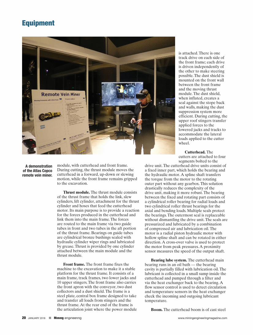
A demonstration of the Atlas Copco remote vein miner.

www.miningengineeringmagazine.com Mınıng engıneerıng JANUARY 2018 21
Equipment
design. The boom has an attachment for the drive unit, the boom lift pin and the lift cylinder. The attachment to the cutterhead is made in such a way that the hydraulic motor could be changed without dismantling the cutterhead.
Tracks. The track drives are of normal excavator type, hydraulic axial piston motor and planetary gear. Tracks are independently maneuvered (as on a bulldozer) and are used for moving and steering the machine and as a stable fixed point during the cutting sequence.
Stingers. Upper stingers are plain hydraulic cylinders used to press the machine down to create a reaction force on the lowered jacks and on both tracks. The pressure in the stingers can be set and monitored by the control system to avoid overloading the paste backfill roof. Many small cylinders are chosen because it’s easier to keep the surface pressure low and well distributed.
Jacks. Two jacks (one on each side) are used to level the mining module before cutting. Levelling is done mainly in pitch but could also be used for small lateral adjustments. Jacks are also designed to take all shearing loads from the thrust module and transfer them to ground.
Power module. The power module holds installations of hydraulic, electric, water, air and control systems and the bolting and meshing unit. It also contains the belt conveyor and the twin track unit.
Cabin. The air-conditioned, falling object protection (FOP)-rated cabin has room for one standing operator (bolting) and one sitting (miner). There will also be an auxiliary seat behind the miner operator. The cabin is placed as close as possible to the bolting and mesh handling unit to provide good vision for the bolter operator. The miner-operator will have limited vison of the cutting head due to dust and will rely on video monitors and automated operation of cutter head movement during sumping into the face. Automated operation of the head position will prevent cutting into the paste fill back, and video icons of the cutter head will show its position during cutting operations. After a face advance (roughly 600 mm or 2 ft) the face is washed down and high definition cameras and LED lighting used to inspect the vein.
Other subsystems. The muck handling system includes the apron and apron wings for
directing the cuttings towards the conveyor. There are two conveyors that direct cuttings from the face to the rear of the machine. The first conveyor in the miner unit is a chain conveyor, the second in the power module is a belt conveyor. The transfer point between the two is in the articulation area. To move the cuttings further aft and to stack a small muck pile, a tail conveyor could be used to directly feed a truck or loader bucket. This conveyor is mounted to the rear end of the power module and is slewable with height adjustable by hydraulic cylinders for loading to trucks.
The dust suppression system includes an inflatable dust shield mounted on the front wall of the miner ventilation filtration unit for removal of dust in front of the dust shield as well as a water mist and direct water spray on the cutterhead.
Elevated walkways provide easy access to the cabin and bolting unit from the rear of the machine while a FOPs-protected walkway can be extended to provide access to the front of the miner where the walls are unsupported. A manually operated gantry crane with a lift block located over the walkway lifts and transports supplies (cutters) to the front of the miner.
Power system — hydraulics. There are two
separate hydraulic systems; actuator and cutter systems. The reason for dividing the systems is to optimize and to reduce contamination risk. The cutterhead drive is the big consumer with large pumps and hydraulic motors. To work at optimum, it needs a thicker oil than the actuator system. The actuator system has a much higher risk for contamination with cylinders, which is also a reason for two separate systems.
There are two hydraulic pumps for the cutter head drive system, each driven by its own electric motor. These hydraulic pumps have their own hydraulic tank with filters and cooling capability. As the pumps in this system work in a closed loop configuration, the only flow through the tank is the cooling flow, thus keeping the size of tank very small.
The actuator hydraulic system has two drive modes. In standard mode, two pumps provide the power off the two main motors (same shaft as cutterhead pumps) and in auxiliary mode a small electric motor drives the hydraulic pumps for the actuator system, tramming, positioning, stingers and jacks. This pump has a bigger tank capability to feed all cylinders when they have maximum extension. The system has its own filters and coolers.
Electrical system. The power system has two
22 JANUARY 2018 Mınıng engıneerıng www.miningengineeringmagazine.com
Equipment
different modes: high power operating on 4,160 V and low power operating on 480 V. The power for cutting is approximately 10 times greater than what is needed for tramming. The motor control center is placed outside the stope on the sublevel of the ramp access to provide for a well-ventilated, temperature-controlled, accessible location.
The 480 V system can be used to tram and control actuators, but not rotate the cutterhead. Power can come from either the mine electrical system, generator or battery. The 4,160 V system is used in the stope when cutting. A remote-controlled switchgear controls the power. The motor control center is placed centrally on the sublevel and a single power cable goes directly from the frequency drive to the machine’s main motors. When the main power is off, a hydraulically driven generator provides 24 V power to run lights and the control system.
With the use of 4,160 V it is possible to use a single, medium-size cable, thus allowing a cable reel located on the power module that will pay out the cable (approximately 150 m or 500 ft total length) while advancing. A hot stick is used to lift the cable to hooks protruding from the paste fill back. When the cable is fully extended, an extension cable can be easily added. The
cable reel pulls the disconnected cable back onto the reel which is then reconnected to the installed extension cable.
The mobile miner is equipped with a rig control system (RCS). This is a computerized control system based on CAN-bus technology. RCS is used for most communication and the steering of actuators, sensorsa and lights and can also be used for remote control of the machine. RCS also has capability to log data if needed.
Project phases and milestonesThe Hecla Mobile Miner project is divided
into six phases:
Phase 1 – Prefeasibility study.Phase 2 – Feasibility study.Phase 3 – Design.Phase 4 – Manufacture and testing.Phase 5 – Test trial at Atlas Copco/Epiroc test
mine.Phase 6 – Field trial at Lucky Friday Mine.
The project is currently in Phase 4. Manufacturing will be complete in January 2019 with deployment of the field trial at the Lucky Friday in early 2020.
Deployment strategyAs stated previously, the mobile miner will be
used to create an underhand longwall by bottom-slicing the 30 Vein. The miner will enter one end of the vein and advance horizontally on strike, mining beneath the engineered paste fill roof until it exits the mineable vein at the end of its strike.
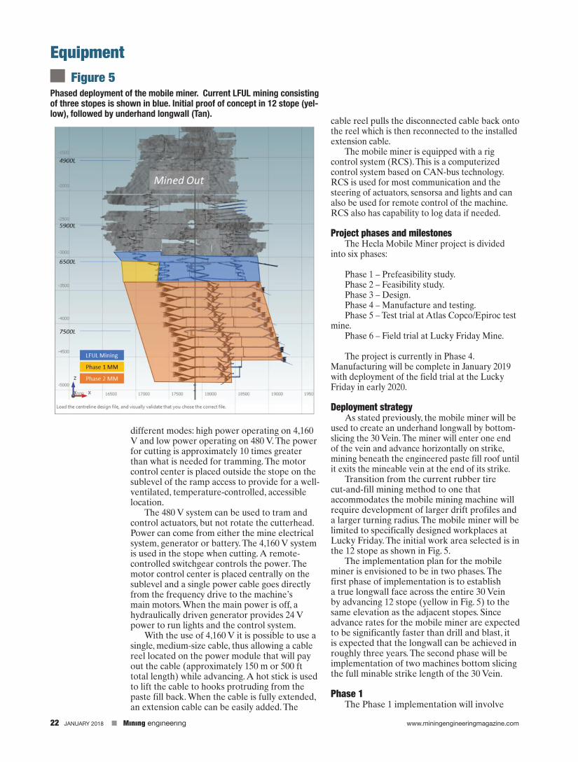
Transition from the current rubber tire cut-and-fill mining method to one that accommodates the mobile mining machine will require development of larger drift profiles and a larger turning radius. The mobile miner will be limited to specifically designed workplaces at Lucky Friday. The initial work area selected is in the 12 stope as shown in Fig. 5.
The implementation plan for the mobile miner is envisioned to be in two phases. The first phase of implementation is to establish a true longwall face across the entire 30 Vein by advancing 12 stope (yellow in Fig. 5) to the same elevation as the adjacent stopes. Since advance rates for the mobile miner are expected to be significantly faster than drill and blast, it is expected that the longwall can be achieved in roughly three years. The second phase will be implementation of two machines bottom slicing the full minable strike length of the 30 Vein.
Phase 1The Phase 1 implementation will involve
Phased deployment of the mobile miner. Current LFUL mining consisting of three stopes is shown in blue. Initial proof of concept in 12 stope (yel-low), followed by underhand longwall (Tan).
Figure 5

www.miningengineeringmagazine.com Mınıng engıneerıng JANUARY 2018 23
Equipment
development of the infrastructure necessary to assemble and maintain the Mobile Miner and cutters. An assembly shop with overhead crane (Fig. 6), will be developed near the 12 stope. To keep large spans at a minimum (shop depth is approximately 2,300 m or 7,500 ft), the crane bay will be limited to travel on one side of the Mobile Miner (power module or mining module). Large excavations have previously been mined at this elevation to support refrigeration system expansion. Lessons learned at Lucky Friday have shown that aligning the drift perpendicular to foliation in the argillite enhances stability significantly.
Mobilization of components underground will be a significant logistical task, as the mine does not intend to curtail production while the machine is being assembled. The transport path for parts is approximately 6.4 km (4 miles) long and must pass down the Silver Shaft to the 5900 mine level. The Silver Shaft is limited to a footprint of 1.8 m x 1.8 m (6 ft x 6 ft) and a weight of 14,000 kg (31,000 lbs). With a machine that is more than 150 t (165 st) fully assembled, the disassembled machine will be reduced to much smaller components for transport. Large components, such as the main frame and cutter head boom will require special shipping down the shaft.
After assembly near the 6500 level, the machine will be used to mine in the lagging 12 stope, starting on the east side and mining a series of horizontal cuts west to the economic limit of the 30 Vein (a strike length of approximately150 m or 500 ft). The machine will then back up to the sublevel to allow for backfilling of the stope. This process will result in establishing a single elevation longwall front.
Phase 2Phase 2 will involve regular mining of the
underhand longwall along the entire strike length. The following major activities will be performed (Fig. 7):
• Establish sublevel ahead of mining.• Combine current three ramps that
service the drill-and-blast stopes into one central ramp with centralized utilities.
• Advance and retreating sequence shown in Fig. 7.
The mining method to utilize the mobile miner across the full length of the 30 Vein (760 m or 2,500 ft) requires a different development layout and production strategy. Conventional rubber tire mechanized cut-and-fill mining is
designed to minimize development in waste. Therefore, the LFUL cut and fill layout has central access into the vein and mines to an efficient ending limit of 90 m (300 ft) per side. The mobile miner will be deployed at one end of the vein and mine to the extent of economic mineralization. Access to the vein will be via a series of slots that range in grade from +20 percent to -20 percent (Fig. 7). One sublevel, as shown in this figure, will service 10 total stope cuts. Phase 2 implementation will allow for a higher utilization of the ore face by dedicating the full strike length to the machine and allowing non-mining activities to occur behind the advancing ore face. As the miner exits the vein, it will move out through the slot to the sublevel and loop back around to start the next cut.
It is planned to utilize two machines mining on successive, staggered horizontal cuts with a lead/lag of approximately 300 m (1,000 ft). This means that the lower miner will be excavating beneath paste fill placed behind the upper miner. Backfilling of the vein will be done behind the advancing mobile miner after it has passed each slot access point (and a new stope entry/exit is established), thereby removing
Phase 1 development for proof of concept testing of the mobile miner showing assembly chamber and access to 12 Stope.
Figure 6

24 JANUARY 2018 Mınıng engıneerıng www.miningengineeringmagazine.com
Equipment
backfill activity from the critical path of ore mining.
The sublevel spacing will be every 45 m (150 vertical ft) and require an increase of waste development over the current LFUL of about 25 percent due to the enlarged drift size and sublevel configuration. Development will be mined using drill-and-blast methods with a strategy to complete development just in time so that the mobile miner is not delayed by development activity. The mining method used in Phase 2 will allow for the mobile miner to remain at the ore face while backfilling occurs behind. This change allows for an estimated 20 percent more time at the face when compared to the current LFUL method.
Summary
The Lucky Friday Mine is one of the deepest mines in the western hemisphere. As the depth has increased, engineering issues typical of deep mines such as seismicity and heat become important aspects of the mine design. A number of revisions to the mining method
Phase 2 deployment – Full 30 vein implementation.
Figure 7
have been made to increase safety and maintain productivity. Hecla Mining is currently making a step-change in deep vein mining technology by developing and employing remote continuous mechanical mining as well as battery technology to ensure the continued safety and productivity of the mine. n
ReferencesBoard, M. P., and S. L. Crouch. (1977) “Mine Planning
to Control Rockburst in Cut and Fill Exca¬vations,” in Design Methods in Rock Mechanics, pp. 249 256. New York: ASCE, 1977.
Board, M. P., and M. D. Voegele. (1981) “Examination and Demonstration of Undercut and Fill Stoping for Ground Control in Deep Vein Mining,” in Application of Rock Mechanics to Cut and Fill Mining, pp. 300 306. London: Institute of Mining & Metallurgy.
CSM (Colorado School of Mines) Earth Mechanics Institute, “DRAFT - Results of Laboratory Linear Cutting Tests and Performance Estimates for Proposed Atlas Copco Mobile Miner/Vein Miner at Lucky Friday Mine” (2017).
Sturgis, G., D. Berberick, M. Board, W. Strickland and M. Swanson. (2017) “Elliptical Shaft Excavation in Response to Depth Induced Ground Pressure”, Deep and High Stress Mining, 2017, Australian Centre for Geomechanics, Perth, Australia, Potvin, Ed.