Embed Size (px)
Citation preview

SERVICE MANUAL
Color Inkjet Printer
Epson WF-7525 / Epson WF-7521 / Epson WF-7520/Epson WF-7515 / Epson WF-7511 / Epson WF-7510/Epson WF-7018 / Epson WF-7015 / Epson WF-7012/Epson WF-7011 / Epson WF-7010
SEMF10-012

Notice:
All rights reserved. No part of this manual may be reproduced, stored in a retrieval system, or transmitted in any form or
by any means, electronic, mechanical, photocopying, recording, or otherwise, without the prior written permission of
SEIKO EPSON CORPORATION.
All effort have been made to ensure the accuracy of the contents of this manual. However, should any errors be
detected, SEIKO EPSON would greatly appreciate being informed of them.
The contents of this manual are subject to change without notice.
The above not withstanding SEIKO EPSON CORPORATION can assume no responsibility for any errors in this
manual or the consequences thereof.
EPSON is a registered trademark of SEIKO EPSON CORPORATION.
Note :Other product names used herein are for identification purpose only and may be trademarks or registered
trademarks of their respective owners. EPSON disclaims any and all rights in those marks.
Copyright 2011 SEIKO EPSON CORPORATION
I&I CS Quality Assurance Department

Safety Precautions
All safety procedures described here shall be strictly adhered to by all parties servicing and maintaining this
product.
DANGER
Strictly observe the following cautions. Failure to comply could result in serious bodily injury or loss of life.
1. Always disconnect the product from the power source and peripheral devices when servicing the product or
performing maintenance.
2. When performing works described in this manual, do not connect to a power source until instructed to do so.
Connecting to a power source causes high voltage in the power supply unit and some electronic components
even if the product power switch is off. If you need to perform the work with the power cable connected to a
power source, use extreme caution to avoid electrical shock.
WARNING
Strictly observe the following cautions. Failure to comply may lead to personal injury or loss of life.
1. Always wear protective goggles for disassembly and reassembly to protect your eyes from ink in working. If
any ink gets in your eyes, wash your eyes with clean water and consult a doctor immediately.
2. When using compressed air products; such as air duster, for cleaning during repair and maintenance, the use
of such products containing flammable gas is prohibited.
PRECAUTIONS
Strictly observe the following cautions. Failure to comply may lead to personal injury or damage of the product.
1. Repairs on Epson product should be performed only by an Epson certified repair technician.
2. No work should be performed on this product by persons unfamiliar with basic safety knowledge required for
electrician.
3. The power rating of this product is indicated on the serial number/rating plate. Never connect this product to
the power source whose voltages is different from the rated voltage.
4. Replace malfunctioning components only with those components provided or approved by Epson;
introduction of second-source ICs or other non-approved components may damage the product and void any
applicable Epson warranty.
5. The capacitors on the Main Board may be electrically charged right after the power turns off or after driving
motors which generates counter electromotive force such as when rotating the PF Roller or when moving the
CR Unit. There is a risk to damage the Main Board if the Head FFC is short-circuited with the capacitors on
the Main Board electrically charged, therefore, after the power turns off or after motors are driven, leave the
printer untouched for approximately 30 seconds to discharge the capacitors before starting disassembly/
reassembly.
6. To prevent the circuit boards from short-circuiting, be careful about the following when handling FFC or
cables.
When handling FFC, take care not to let the terminal section of FFC touch metal parts.
When connecting cables/FFC to the connectors on circuit boards, connect them straight to the connectors to avoid
slant insertion.
7. In order to protect sensitive microprocessors and circuitry, use static discharge equipment, such as anti-static
wrist straps, when accessing internal components.
8. Do not tilt this product immediately after initial ink charge, especially after performing the ink charge several
times. Doing so may cause ink to leak from the product because it may take some time for the waste ink pads
to completely absorb ink wasted due to the ink charge.
9. Never touch the ink or wasted ink with bare hands. If ink comes into contact with your skin, wash it off with
soap and water immediately. If you have a skin irritation, consult a doctor immediately.
10. When disassembling or assembling this product, make sure to wear gloves to avoid injuries from metal parts
with sharp edges.
11. Use only recommended tools for disassembling, assembling or adjusting the printer.
12. Observe the specified torque when tightening screws.
13. Be extremely careful not to scratch or contaminate the following parts.
Nozzle plate of the printhead
CR Scale
PF Scale
Coated surface of the PF Roller
Gears
Rollers
LCD
Scanner Sensor
Exterior parts
14. Never use oil or grease other than those specified in this manual. Use of different types of oil or grease may
damage the component or give bad influence on the printer function.
15. Apply the specified amount of grease described in this manual.
16. Make the specified adjustments when you disassemble the printer.
17. When cleaning this product, follow the procedure described in this manual.
18. When transporting this product after filling the ink in the printhead, pack the printer without removing the
ink cartridges in order to prevent the printhead from drying out.
19. Make sure to install antivirus software in the computers used for the service support activities.
20. Keep the virus pattern file of antivirus software up-to-date.
21. When disassembling/reassembling this product, if you find adhesive power of the double-sided tape which
secure the parts or FFC is not enough, replace the tape with new one and attach it correctly to the specified
points where the parts or FFC should be secured.
22. Unless otherwise specified in this manual, the labels attached on the returned product should be transferred to
the corresponding attachment positions on the new one referring to the labels on the returned product.

About This Manual
This manual, consists of the following chapters, is intended for repair service personnel and includes information
necessary for properly performing maintenance and servicing the product.
CHAPTER 1. PRODUCT DESCRIPTIONS
Provides a general overview and specifications of the product.
CHAPTER 2. OPERATING PRINCIPLES
Describes the theory of mechanical operations of the product.
CHAPTER 3. TROUBLESHOOTING
Describes the step-by-step procedures for the troubleshooting.
CHAPTER 4. DISASSEMBLY / REASSEMBLY
Describes the disassembly/reassembly procedures for main parts/units of the product.
CHAPTER 5. ADJUSTMENT
Describes the required adjustments for servicing the product.
CHAPTER 6. MAINTENANCE
Describes maintenance items and procedures for servicing the product.
Symbols Used in this Manual
Various symbols are used throughout this manual either to provide additional information on a specific topic or
to warn of possible danger present during a procedure or an action. Pay attention to all symbols when they are
used, and always read explanation thoroughly and follow the instructions.
Indicates an operating or maintenance procedure, practice or condition that, if not strictly observed,
could result in serious injury or loss of life.
Indicates an operating or maintenance procedure, practice, or condition that, if not strictly observed,
could result in bodily injury, damage or malfunction of equipment.
May indicate an operating or maintenance procedure, practice or condition that is necessary to
accomplish a task efficiently. It may also provide additional information that is related to a specific
subject, or comment on the results achieved through a previous action.
For Chapter 4 “Disassembly/Reassembly”, symbols other than indicated above are used to show additional
information for disassembly/reassembly. For the details on those symbols, see "4.2 Disassembly/Reassembly
Procedures (p46)".

Revision Status
Revision Date of Issue Description
A Aug. 24, 2011 First Release

7
Epson WF-7520/7510/7010 series Revision A
Contents
Chapter 1 Product description
1.1 Features . ................................................................................................................................................................... 10
1.2 Printing Specifications . ............................................................................................................................................ 12
1.2.1 Basic Specifications. ........................................................................................................................................ 12
1.3 Scanner Specifications (WF-7520/7510 series only) ............................................................................................... 13
1.3.1 Basic Specifications. ........................................................................................................................................ 13
1.4 Control Panel. ........................................................................................................................................................... 14
1.4.1 Operation Buttons. ........................................................................................................................................... 14
1.4.2 LEDs and LCD Indications . ............................................................................................................................ 16
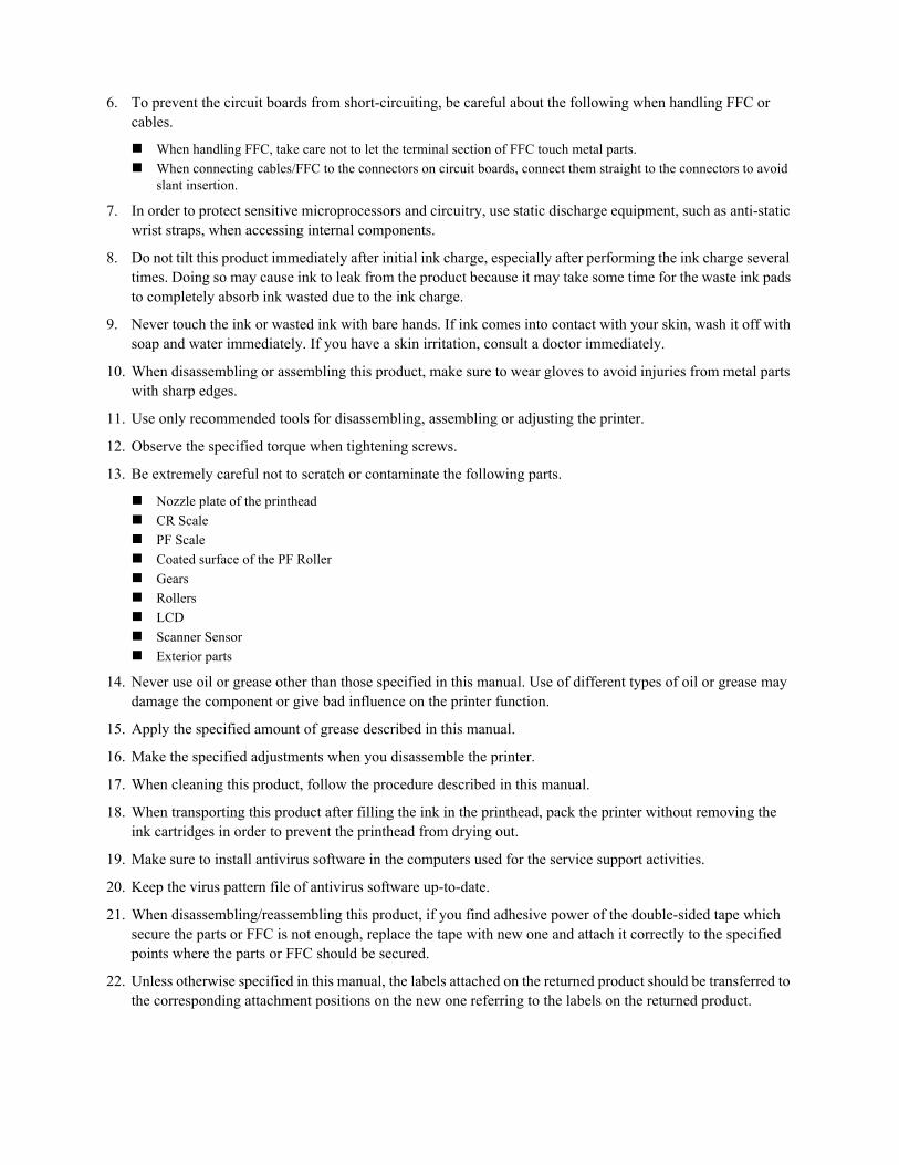
1.5 Various Settings . ...................................................................................................................................................... 19
1.5.1 Panel Operation . .............................................................................................................................................. 19
1.5.1.1 Setup Menu Configuration (WF-7520/7510 series only) ....................................................................... 19
1.5.1.2 Forced Power OFF (WF-7010 series only)............................................................................................. 20
1.5.1.3 Printer Status Sheet . ................................................................................................................................ 20
Chapter 2 Operating Principles
2.1 Overview . ................................................................................................................................................................. 22
2.2 Motors and Sensors . ................................................................................................................................................ 22
2.3 Optical Sensor Control . ............................................................................................................................................ 25
2.4 Power-On Sequence . ................................................................................................................................................ 26
Chapter 3 Troubleshooting
3.1 Troubleshooting. ....................................................................................................................................................... 30
3.1.1 Error Message List. .......................................................................................................................................... 30
3.1.2 Troubleshooting Workflow . ............................................................................................................................ 31
3.1.3 Fatal Error Code . ............................................................................................................................................. 33
3.1.4 FAX Troubleshooting (WF-7520/7510 series only) ....................................................................................... 37
3.1.4.1 FAX Log . ................................................................................................................................................ 37
3.1.4.2 Error Code/Superficial Phenomenon-Based Troubleshooting ............................................................... 42
Chapter 4 Disassembly/Reassembly
4.1 Overview . ................................................................................................................................................................. 45
4.1.1 Tools . ............................................................................................................................................................... 45
4.1.2 Jigs . .................................................................................................................................................................. 45
4.2 Disassembly/Reassembly Procedures . ..................................................................................................................... 46
4.2.1 Parts/Units Need to be Removed in Advance ................................................................................................. 46
4.2.2 Disassembling Flowchart . ............................................................................................................................... 48
4.2.2.1 Exterior Parts . ......................................................................................................................................... 48
4.2.2.2 Printer Mechanism. ................................................................................................................................. 52
4.3 Detailed Disassembly/Reassembly Procedure for each Part/Unit............................................................................ 55
4.4 Routing FFCs/cables . ............................................................................................................................................... 63
4.5 Connector Summary. ................................................................................................................................................ 67

8
Epson WF-7520/7510/7010 series Revision A
Chapter 5 Adjustment
5.1 Required Adjustments . ............................................................................................................................................. 69
5.2 Details of Adjustments . ............................................................................................................................................ 75
5.2.1 PF Timing Belt Tension Check . ...................................................................................................................... 75
5.2.2 Checking the Platen Gap . ................................................................................................................................ 76
5.2.3 Scanner Timing Belt Tension Check............................................................................................................... 77
5.2.4 MAC Address Setting. ..................................................................................................................................... 78
Chapter 6 Maintenance
6.1 Overview . ................................................................................................................................................................. 80
6.1.1 Cleaning. .......................................................................................................................................................... 80
6.1.2 Lubrication. ...................................................................................................................................................... 80
6.2 Lubrication Points and Instructions. ......................................................................................................................... 81

CHAPTER 1
PRODUCT DESCRIPTION

Product description Features 10
Epson WF-7520/7510/7010 series Revision A
1.1 Features
WF-7520/7510/7010 series are an A3 color inkjet printer based on Epson WorkForce 840/Epson Stylus Office
BX925FWD. Major features are as follows.
Common futures
Printer
Maximum print speed: 15 ppm (A4, monochrome, draft printing mode)
O6-Chip Turbo 2 Printhead (Black: 128 nozzles x 3, Color: 128 nozzles x 1 per color)
Maximum print resolution: 5760 x 1440 dpi
Auto duplex printing up to A3 paper with the Duplex Unit (WF-7520/7010 series only)
Four independent ink cartridges are installed (pigment inks)
Interface
In addition to USB connection, wired/wireless LAN connection are available
Scanner (WF-7520/7510 series only)
CIS type sensor (scanning resolution: 1200 x 2400 dpi)
ADF up to A3 paper scanning*
Note"*": Auto duplex scanning is available only for WF-7520 series. (A4 or letter sized paper only)
Differences between the models
WF-7520/7510/7010 series are different as shown below.
Note *: The availability of the WiFi varies depending on the destinations.
Available: EHC/Euro/CISMEA/ESP/ETT/EKL
Not available: EAL/Latin/EAL/ECC/EHK
In this chapter, the product names are called as follows:
WF-7520 series: Epson WF-7525/Epson WF-7521/Epson WF-7520
WF-7510 series: Epson WF-7515/Epson WF-7511/Epson WF-7510
WF-7010 series: Epson WF-7018/Epson WF-7015/Epson WF-7012/Epson WF-7011/
Epson WF-7010
Table 1-1. Differences between the Models
Item WF-7520 series WF-7510 series WF-7010 series
LCD display size 2.5 inch 2.5 inch No
Auto duplex printing Yes No Yes
Scanner / ADF Yes Yes No
USB host
(for PictBridge / Backup of an external storage device)Yes Yes No
FAX Yes Yes No
Wi-Fi Yes Yes Yes*
2nd cassette Yes No Yes

Product description Features 11
Epson WF-7520/7510/7010 series Revision A
External view
Figure 1-1. External View
Note *1: Paper support for rear ASF and stacker are closed. Rubber feet are included.
*2: Excluding the weight of ink cartridges and power cable.
Table 1-2. Dimensions
Model Dimensions (W x D x H)*1 Weight*2
WF-7520 series 559 mm x 418 mm x 365 mm 18.9 kg
WF-7510 series 559 mm x 418 mm x 287 mm 15.6 kg
WF-7010 series 558 mm x 414 mm x 264 mm 12.3 kg
WF-7520 series WF-7510 series WF-7010 series

Product description Printing Specifications 12
Epson WF-7520/7510/7010 series Revision A
1.2 Printing Specifications
1.2.1 Basic Specifications
Note *: For paper thickness: 0.11 mm, 80 g/m2.
Table 1-3. Printer Specifications
Item Specification
Print method On-demand ink jet
Nozzle configuration Black: 384 nozzles (128 nozzles x 3)
Color: 384 nozzles (128 nozzles x 1 per color)
Color Black, Cyan, Magenta, Yellow
Print direction Bi-directional minimum distance printing, Unidirectional printing
Print resolution Horizontal x Vertical (dpi)
• 360 x 120
• 360 x 360
• 360 x 720
• 720 x 720
• 1440 x 720
• 5760 x 1440
Control code • ESC/P Raster command
• ESC/P-R (RGB) command
Input buffer size Printing from PC: 64 KBytes
Stand-alone printing: 132 KBytes
Paper feed method Friction feed
Paper feed amount 250 pages (plain paper*), 20 pages (photo paper), 50 pages (postcard)
Paper path Front feed, front out
PF interval 0.01764 mm (1/1440 inch)

Product description Scanner Specifications (WF-7520/7510 series only) 13
Epson WF-7520/7510/7010 series Revision A
1.3 Scanner Specifications (WF-7520/7510 series only)
1.3.1 Basic Specifications
Note *: WF-7520 series only
Table 1-4. Basic Specifications
Item Specification
Scanner type Flatbed, color
Scanning method Moving carriage, stationary document
Home position The rear left corner
Photoelectric device CIS
Light source LED
Maximum document sizes A3 or US B (tabloid)
Scanning range 11.7” x 17” (297 mm x 431.8 mm)
Maximum resolution Main scan: 1,200 dpi
Sub scan: 2,400 dpi
Maximum effective pixels 14,040 x 20,400 pixels
Pixel depth 16 bit per pixel (input) and 1 bit or 8 bit per pixel (output)
Table 1-5. ADF Specifications
Item Specification
Document loading Face-up
Maximum document sizes A4 to A3/tabloid
Supported paper type Plain paper only
Paper thickness 64 to 95 g/m2
Maximum number of documents which can be set 30 sheets or 3 mm at maximum
Document path Feeds from upper tray and ejects to lower tray
Document set position Center
Auto duplex scanning* A4 or US Letter only

Product description Control Panel 14
Epson WF-7520/7510/7010 series Revision A
1.4 Control Panel
1.4.1 Operation Buttons
The operation buttons, LEDs, and LCD are shown below. See Table 1-6 and Table 1-7 for the functions.
WF-7520/7510 series
Figure 1-2. Control Panel (WF-7520/7510 series)
Table 1-6. Operation Buttons, LEDs and LCD (WF-7520/7510 series)
Item Icon Name Function
LCD Indicates the printer status, error, and menu screen.
Button/
touch panel
Power Turns the power on/off.
Photo Enters photo mode.
Display/Crop• Enters zoom setting screen for selected image.
• Switches preview screens on LCD.
Copy Enters copy mode.
Reduce/Enlarge Specifies copy magnification.
Quality Specifies print quality.
2-Sided Specifies auto duplex print setting. (WF-7520 series only)
Setup Enters setup mode.
Help Displays help for solutions to problems.
Reset Resets the current setting and displays the home screen.
Arrows
• Selects menus.
• Specifies the number of copies.
• Moves the cursor in fax mode.
OK Activates the setting you have selected.
Menu Displays detailed settings for each mode.
Back Cancels/returns to the previous menu.
Stop Stops printing.
Ten key
• Specifies the date/time
• Specifies the number of copies
• Specifies fax numbers
Fax Enters fax mode.
Auto Answer Turns on/off auto answer mode.
Redial/Pause• Displays the last number dialed.
• Inserts a pause symbol (-) when entering numbers in fax mode.
Speed Dial Displays speed dial list in fax mode.
Scan Enters scan mode.
Start Starts copying in each mode.
Start
Photo Fax Scan
Menu
Start
Back
Stop
Copy
WF-7520 series only
- , ,

Product description Control Panel 15
Epson WF-7520/7510/7010 series Revision A
Note : See "1.4.2 LEDs and LCD Indications (p16)" for more details about the LCD.
WF-7010 series
Figure 1-3. Control Panel (WF-7010 series)
Note : See "1.4.2 LEDs and LCD Indications (p16)" for more details about the LEDs.
Note *: The corresponding color LED is indicated.
LED
Power• Lights when the printer is on.
• Flashes when the printer is in process.
Network Indicates the network connection status.
Auto Answer On when the fax is in auto answer mode.
Table 1-7. Operation Buttons and LEDs (WF-7010 series)
Item Icon Name Function
Button
Power Turns the power on/off.
Network status sheet Prints a network status sheet.
--- Wi-Fi Configures the wireless network.
Paper feed/eject• Loads or ejects paper.
• Resumes printing after a paper out error, multiple page feed error.
Ink• Starts ink replacement.
• Starts head cleaning.
Cancel Cancels printing during a print job.
LED
Power• Lights when the printer is on.
• Flashes when the printer is in process.
Network Indicates the network connection status.
Paper Indicates error status for paper.
Ink* Indicates error status for ink.
Table 1-6. Operation Buttons, LEDs and LCD (WF-7520/7510 series)
Item Icon Name Function
Note : The WiFi logo and button on the control panel vary
depending on the destinations. (See Table 1-1.)

Product description Control Panel 16
Epson WF-7520/7510/7010 series Revision A
1.4.2 LEDs and LCD Indications
Table 1-8. LEDs and LCD Indications
Status
WF-7010 series WF-7520/7510 series
LEDLCD Message
Power Network Paper Ink
Operating
Printer fatal errorFlash at
high speed
Flash at
high speed
Flash at
high speed
Flash at
high speed
Printer error. Turn power off and then on
again. For details, see your documentation or
visit Epson.com.
Printer fatal error
(paper jam)
Flash at
high speed
Flash at
high speed
Flash at
high speed
Flash at
high speed
Paper jam inside, in back, or in ADF. Press
OK to see how to remove jammed paper.
Scanner fatal error*1 --- --- --- ---
Scanner error. Turn power off and then on
again. In the error is not fixed, visit
Epson.com for technical support.
ADF fatal error*1 --- --- --- --- Automatic Document Feeder (ADF) error.
ADF paper jam error*1 --- --- --- ---Paper jam in the Automatic Document
Feeder (ADF).
Waste ink pad end error Flash*2 ---Alternate
flash 1
Alternate
flash 2
A printer's ink pad is at the end of its service
life. Please contact Epson Support.
Waste ink pad near end
errorFlash*2 ---
Alternate
flash 1
Alternate
flash 2
A printer's ink pad is nearing the end of its
service life. Please contact Epson Support.
Paper jam error Flash*2 --- Flash ---Paper jam. Press OK to see how to remove
jammed paper.
No paper cassette error Flash*2 --- ON ---Load Cassette correctly and press or
.
Paper out error Flash*2 --- ON ---Paper out or paper jam. Check paper size and
load paper in paper cassette.
Multi-feed error Flash*2 --- ON ---Multi-page feed error. Remove and reload
the paper, then press or .
Paper length mismatch
error for duplex
printing*3Flash*2 --- ON ---
Incorrect paper size detected. Load correct
paper size and press or .
Paper size mismatch
errorFlash*2 --- ON ---
No paper source matches paper size setting.
Load appropriate paper in Cassette 1. Press
or .
Incorrect paper size
error*1 --- --- --- ---Paper size is incorrect. Load US B 11x17in
size plain paper in Cassette.
Printer/printer driver
mismatch errorFlash*2 ---
Flash at
high speed
Flash at
high speedError Press .
Cover open error Flash --- Flash 2 Flash 2 Close the scanner unit.
Ink end error Flash*2 --- --- ON*4You need to replace the following ink
cartridge(s).
<Ink Cartridges>XXXXXXX*5
Ink cartridge detection
errorFlash*2 --- --- ON*4
Cannot recognize the following cartridge(s).
Try installing them again.
<Ink Cartridges>XXXXXXX*5
Ink cartridge detection
error (non-Epson
cartridge)
Flash*2 --- --- ON*4Ink cartridge is not recognized. Please
replace the cartridge.
<Ink Cartridges>XXXXXXX*5
No ink cartridge error Flash*2 --- --- ON*4The cartridge is installed incorrectly. Press it
down until it clicks.
<Ink Cartridges>XXXXXXX*5

Product description Control Panel 17
Epson WF-7520/7510/7010 series Revision A
Operating
Starting filling of ink
(after carriage moves)Flash --- --- ---
Replace the cartridge(s) and close the
scanner unit.
<Ink Cartridges>XXXXXXX*5
Ink cartridge cover open
errorFlash*2 --- --- ---
The ink cartridge cover is open. Close the ink
cartridge cover.
Starting initialization Flash --- --- ---Install the ink cartridges. See the setup sheet
for details.
Initializing Flash --- --- ---
Initializing...Please wait.
Do not turn off until initialization is
complete. This takes about 7 minutes.
Filling of ink Flash --- --- --- Charging ink...Please wait.
Checking ink cartridges Flash --- --- --- Checking the ink cartridges...
Drying 1st side
(printing from PC)Flash --- --- ---
Printing 2-sided document. Do not touch the
paper in the output tray until printing is
complete.
Printing (PC) Flash --- --- --- Printing...
Printing nozzle check
patternFlash --- --- --- Printing...
Printing printer status
sheetFlash --- --- --- Printing...
Printing (UPNP) Flash Flash --- --- Printing...
Receiving data Flash Flash --- --- Receiving data...
Canceling (PC)*6 Flash --- --- --- Canceling...
Cleaning (PC) Flash --- --- --- Cleaning print head...Please wait.
Print head cleaning Flash --- --- --- Cleaning print head...Please wait.
Canceling nozzle check
pattern printFlash --- --- --- Canceling...
Canceling printer status
sheet printFlash --- --- --- Canceling...
Initializing network Flash*2 Flash --- --- ---
Waiting for network
initializationFlash*2 --- --- --- ---
Network initialization
(LED ON)OFF*2 ON --- --- ---
Network initialization
(LED OFF)OFF*2 OFF --- --- ---
Preparing to update
firmware (cancel OK)ON*2 Flash at
high speed--- --- Preparing to update...
Updating firmware Flash*7 OFF OFF OFF
Updating firmware...Do not turn power off.
It turns off and on automatically when
complete.
Preparing to update
firmwareON*2 Flash at
high speed--- --- Preparing to update...
Canceling firmware
updateON*2 Flash at
high speed--- --- Canceling...
Table 1-8. LEDs and LCD Indications
Status
WF-7010 series WF-7520/7510 series
LEDLCD Message
Power Network Paper Ink

Product description Control Panel 18
Epson WF-7520/7510/7010 series Revision A
Note : Flash Turns on and off at intervals of 1.25 seconds.
Flash 2 On for 0.5 sec., Off for 0.5 sec., On for 0.5 sec. and Off for 1.0 sec.
Flash at high speed Turns on and off at intervals of 0.5 seconds.
Alternate flash 1 Same as “Flash”
Alternate flash 2 Turns on and off at intervals of 1.25 seconds.
Note *1: WF-7520/7510 series only
*2: Flashes if the status arises when printing starts or when the printer starts up, but lights if the status arises when printing is
complete.
*3: WF-7520/7010 series only
*4: The corresponding ink LED flashes/lights.
*5: The corresponding ink cartridge product number is indicated.
*6: Occurs when cancelling printing from PC, UPNP printing.
*7: Lights and then flashes.
*8: This does not occur independently. Occurs together with operating or standby state.
Operating
Powering OFFFlash at
high speed--- --- --- Turning off...
Powering ON Flash Flash --- --- Starting up...Please wait.
Feeding a paper
(load/eject)Flash --- --- --- Printing...
Standby
No error ON --- --- --- ---
Ink level low ON*2 --- --- Flash*4 Ink low.
Waste ink pad near end
errorON*2 ---
Alternate
flash 1
Alternate
flash 2
A printer's ink pad is nearing the end of its
service life. Please contact Epson Support.
Requiring ink cartridges
(carriage is at the
replacement position)
Flash --- --- ---
Replace the cartridge(s) and close the
scanner unit.
<Ink Cartridges>XXXXXXX*5
Ink end error
(during Bk mode)ON*2 --- --- ON*4 You can temporarily copy, print and fax in
B&W on plain paper on the next job.
Ink end error
(out of Bk mode)ON*2 --- --- ON*4
You need to replace the following ink
cartridge(s).
<Ink Cartridges>XXXXXXX*5
No ink cartridge error ON*2 --- --- ON*4The cartridge is installed incorrectly. Press it
down until it clicks.
<Ink Cartridges>XXXXXXX*5
Ink cartridge detection
errorON*2 --- --- ON*4
Cannot recognize the following cartridge(s).
Try installing them again.
<Ink Cartridges>XXXXXXX*5
Ink cartridge detection
error (non-Epson
cartridge)
ON*2 --- --- ON*4Ink cartridge is not recognized. Please
replace the cartridge.
<Ink Cartridges>XXXXXXX*5
Operating/
Standby*8
When starting up --- Flash --- --- ---
Not connected --- --- --- --- ---
Connected via wired
LAN (with IP)--- ON --- --- ---
Table 1-8. LEDs and LCD Indications
Status
WF-7010 series WF-7520/7510 series
LEDLCD Message
Power Network Paper Ink
Product description Various Settings 19
Epson WF-7520/7510/7010 series Revision A
1.5 Various Settings
1.5.1 Panel Operation
1.5.1.1 Setup Menu Configuration (WF-7520/7510 series only)
The following explains the setup menu structure and the outline of the menu functions.
Note *1: WF-7520 series only
*2: Not available for some destinations.
Table 1-9. Setup Menu Configuration (WF-7520/7510 series only)
Menu Description
Setup Ink Levels --- Displays the status of ink cartridges.
Maintenance Print Head Nozzle Check Prints a nozzle check pattern.
Print Head Cleaning Runs a print head cleaning.
Print Head Alignment Prints a gap adjustment pattern.
Ink Cartridge Replacement Starts ink cartridge replacement.
Printer Setup Paper Size Loaded*1 Selects the paper size.
Sound Turns the sound on/off.
Screen Saver*2 Configures the screen saver setting.
Display Format Specifies display format for the images in the memory card.
Date/Time Selects display format for data/time.
Daylight Saving Time Selects daylight saving time.
Country/Region Selects country/region.
Language Selects the language displayed on the LCD.
Paper Size Notice*1 Checks the paper size and selects whether to alert users when an
error occurs (Off/On).
Wi-Fi/Network
Settings
Wi-Fi Setup Selects a connection method for wireless LAN.
General Network Setup Configures the general setting for network.
Wi-Fi/Network Connection
Check
• Checks the network connection status.
• Prints the connection check result.
Confirm Network Settings • Displays the network information.
• Prints a network status sheet.
File Sharing Setup USB Sets the access priority when accessing the storage device
connected to the USB host port to USB or Wi-Fi/Network.Wi-Fi/Network
External Device
Setup
Print Settings Configures the print and paper settings when printing an image in
external device.
Photo Adjustments Configures the color correction for photo.
Print Status Sheet --- Prints a printer status sheet.
Restore Default
Settings
Reset Fax Send/Receive
SettingsInitializes the fax send/receive settings.
Reset Fax Data Settings Deletes the fax data settings.
Reset Wi-Fi/Network
SettingsInitializes the Wi-Fi/network settings.
Reset All except Wi-Fi/
Network & Fax SettingsInitializes the settings except Wi-Fi/network/fax settings.
Reset All Settings Initializes the all settings.

Product description Various Settings 20
Epson WF-7520/7510/7010 series Revision A
1.5.1.2 Forced Power OFF (WF-7010 series only)
For WF-7010 series, the power can be turned off forcibly by the following panel operation. If the power is turned
off forcibly, the same process of the normal power-off is executed.
Operation method
1. Press the power button and then stop button, and hold down the buttons for seven seconds or more.
2. When the Power LED starts flashing, release the buttons.
1.5.1.3 Printer Status Sheet
WF-7520/7510/7010 series print the printer status sheet by the following operation.
Note : When printing the network status sheet to check the network information, follow the procedure below.
WF-7520/7510 series: Select “Wi-Fi/Network Settings” - “Confirm Wi-Fi/Network Settings”, and press the OK button.
(See "1.5.1.1 Setup Menu Configuration (WF-7520/7510 series only) (p19)".)
WF-7010 series: Press the “network status sheet” button. (See "1.4.1 Operation Buttons (p14)".)
Table 1-10. Status Sheet
Model Procedure
WF-7520/7510 series 1. Press the setup button.
2. Select “Print Status Sheet” from the setup menu.
3. Press the OK button.
WF-7010 series Turn the power on while pressing the paper feed/eject button.

CHAPTER 2
OPERATING PRINCIPLES

Operating Principles Overview 22
Epson WF-7520/7510/7010 series Revision A
2.1 Overview
This chapter describes the operating principles of WF-7520/7510/7010 series printer mechanism.
2.2 Motors and Sensors
The following table lists the motors and sensors of WF-7520/7510/7010 series.
Printer Mechanism
Figure 2-1. Motors & Sensors (Printer Mechanism)
In this chapter, the product names are called as follows:
WF-7520 series: Epson WF-7525/Epson WF-7521/Epson WF-7520
WF-7510 series: Epson WF-7515/Epson WF-7511/Epson WF-7510
WF-7010 series: Epson WF-7018/Epson WF-7015/Epson WF-7012/Epson WF-7011/
Epson WF-7010
Table 2-1. List of Motors & Sensors (Printer Mechanism)
Mechanism Motor or Sensor No.
Printhead ---
Carriage mechanism CR Motor A
CR Encoder 1
PW Sensor 2
Cover Open Sensor 3
Paper loading/feed mechanism PF Motor B
PF Encoder 4
PE Sensor 5
Pre-PE Sensor 6
Paper Stopper Lever Sensor 1st 7
A
Printhead
1
2
5
3
4
B
7
6

Operating Principles Motors and Sensors 23
Epson WF-7520/7510/7010 series Revision A
2nd cassette (WF-7520/7010 series only)
Figure 2-2. Motors & Sensors (2nd Cassette)
Table 2-2. List of Motors & Sensors (2nd Cassette)
Mechanism Motor or Sensor No.
Paper loading/feed mechanism Pickup Motor A
Pickup Encoder 1
Paper Stopper Lever Sensor 2nd 2
2
1
A

Operating Principles Motors and Sensors 24
Epson WF-7520/7510/7010 series Revision A
Scanner (WF-7520/7510 series only)
Figure 2-3. Motors & Sensors (Scanner)
Figure 2-4. Motors & Sensors (ADF)
Table 2-3. List of Motors & Sensors (Scanner)
Mechanism Motor or Sensor No.
Scanner mechanism Scanner Motor Assy A
CIS Unit 1
Table 2-4. List of Motors & Sensors (ADF)
Mechanism Motor or Sensor No.
ADF mechanism ADF Motor A
ADF PE Sensor 1
ADF DOC Sensor 2
ADF Encoder 3
1
A
A
1
2
3

Operating Principles Optical Sensor Control 25
Epson WF-7520/7510/7010 series Revision A
2.3 Optical Sensor Control
WF-7520/7510/7010 series uses the optical sensor to control itself. The following describes the operating
principles of optical sensor control.
Control method
To ensure accurate printing, each part must be controlled to make an adequate amount (time) of movement. The
optical sensors read the amount (time) of movements as follows to printer to control it for achieving accurate printing.
1. Rotates the motors for control of the printer, and transmits drive force to the each part via the gear or the
timing belt.
2. The encoder reads the drive amount of each part from the scale one by one to printer to monitor that the part
drives for an adequate amount (time).
Controlled parts
The following table lists where the optical sensor control is used.
Note *1: See Fig. 2-1 (p22) and Fig. 2-2 (p23) for the positions of the parts.
*2: WF-7520/7010 series only
*3: WF-7520/7510 series only
Operating principles
The following describes the PF drive control as an example of the actual operation for the optical sensor.
The PF scale consists of light-passing and light-blocking portions on its surface, and runs through the slit between
the encoder’s light-emitting and light-receiving devices. While the printer is operating, the encoder always emits
light from light-emitting device toward the light-receiving device, and the light-receiving device detects light when
the light is transmitted through the light-passing portion of the scale, and does not detect light when the light is
blocked by the light-blocking portion of the scale. According to the counts of light-detected and non detected times,
the printer controls paper feed drive direction and amount.
When the encoder cannot read light-emitting/blocking counts correctly due to the misalignment, broken or
contaminated scale, paper jam, foreign object and increasing a load, the fatal error occurs and the printer stops.
Figure 2-5. PF Drive Control Section
Table 2-5. Controlled Parts*1
Item Motor Scale Encoder Transmission method
PF/ASF (1st cassette) PF Motor PF Scale PF Encoder PF Timing Belt
CR CR Motor CR Scale CR Encoder CR Timing Belt
ASF (2nd cassette*2) Pickup Motor Pickup Scale Pickup Encoder Gear
ADF*3 ADF Motor ADF Scale ADF Encoder Gear
PF EncoderWith cover
Without cover (light-emitting and receiving devices)
Left side of Printer Mechanism
PF Encoder
Light passes
Light does not pass
PF Scale
PF Timing Belt PF Motor

Operating Principles Power-On Sequence 26
Epson WF-7520/7510/7010 series Revision A
2.4 Power-On Sequence
This section describes the power-on sequences for this product. The preconditions are as follows.
Condition 1: Normal power-on sequence (See Table 2-6.)
Turning on the printer after turning it off without an error.
Initial ink charge has finished and every cartridge has sufficient ink.
No paper on the paper path.
The Printhead is capped with the Cap of the Ink System Assy.
The Carriage is normally fixed by the CR Lock.
Condition 2: Power-on sequence after recovering from a paper jam error (See Table 2-7.)
Turning on the printer after turning it off with a paper jam error.
There still remains paper on the paper path out of the detecting area of the PE sensor.
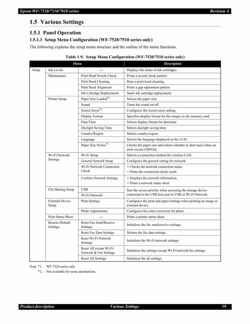
Table 2-6. Condition 1: Normal Power-on Sequence *1
Operation*2Carriage/PF Roller
movement and
position*3
1. Printhead initialization
1-1.Initializes the Printhead, and checks for the fuse on the board in the Printhead.*4
2. Checking for waste ink overflow
2-1.Checks the waste ink counter if the waste ink overflow is occurring.
3. Avoiding deadlock sequence *5
3-1.The carriage moves to the 0-digit side slowly and confirms it touches the Right Frame.
3-2.The carriage slightly moves to the 130-digit side slowly.
3-3.The PF Motor rotates clockwise, and releases the CR lock.
4. Seeking the home position
4-1.The carriage moves to the 0-digit side slowly and confirms it touches the Right Frame. The position when it
touches the Right Frame is set as the origin position temporarily.
4-2.The carriage slowly moves to the CR lock set position.
4-3.The PF Motor rotates counterclockwise, and sets the CR lock.
4-4.The carriage moves to the 130-digit side slowly and confirms it touches the CR lock.
4-5.The carriage slowly moves toward the 0-digit side and reaches the CR lock set position.
4-6.The PF Motor rotates clockwise, and releases the CR lock.
4-7.The carriage moves to the 130-digit side slowly and confirms it does not touch the CR lock.
4-8.The carriage slowly moves to its home position, and the origin position is fixed.
Afterward, the carriage position is monitored according to the signals from the CR Encoder.
130
130
130
130
130
130
130
130
130
130
130
130
130
Operating Principles Power-On Sequence 27
Epson WF-7520/7510/7010 series Revision A
Note *1: The PF motor drive is not transmitted to the Pickup Roller during this power-on sequence.
*2: The rotation directions of the PF Motor are as follows.
Clockwise: Paper is fed normally
Counterclockwise: Paper is fed backward
*3: The conditions of the CR lock are as follows.
Red CR lock is set
White CR lock is released
*4: The fatal error occurs if there is a problem such as the fuse blew.
*5: Confirm that the CR lock is not get stuck in the gap of the carriage or any other parts preventing the carriage from moving.
*6: Eject paper if any.
*7: Executed when the detected temperature is under 5 oC (41oF) by the thermistor on the Printhead.
*8: The empty suction operation may occur depending on situations.
5. PF initialization
5-1.The PF Motor rotates clockwise for approximately one second.
5-2.The PE sensor detects if paper exists*6 and the PF Motor rotates clockwise for approximately 0.5 second.
6. Low temperature operation sequence*7
6-1.The carriage moves back and forth between the CR lock and the 130-digit side for two times.
7. PF measurement and PW sensor initialization
7-1.The carriage slowly moves to the 130-digit side.
7-2.The carriage moves to the VHCheck position quickly and stops; meanwhile the voltage values detected by the PW
sensor at the specified three points are recorded. At the same time, the PF Motor rotates clockwise and its load is
measured.
7-3.The carriage detects the voltage of the PW sensor at the carriage stop position (the black area at the Paper Guide
Front).
7-4.The carriage returns near its home position. At the same time, the PF Motor rotates clockwise and its load is
measured.
8. Detecting ink cartridge and initializing ink system*8
8-1.After the carriage slightly moves to the 130-digit side and checks the ink end sensor, detects the ink remaining.
8-2.The carriage slowly returns to its home position.
8-3.The carriage slowly moves to the 0-digit side to the CR lock set position.
8-4.The PF Motor rotates counterclockwise and sets the CR lock.
8-5.The carriage slowly returns to its home position.
Table 2-6. Condition 1: Normal Power-on Sequence *1
Operation*2Carriage/PF Roller
movement and
position*3
130
130
130
130
130
130
130
130
130
130
130
130

Operating Principles Power-On Sequence 28
Epson WF-7520/7510/7010 series Revision A
Note *1: “Paper exists” is detected when the carriage touches the paper. When “paper does not exist” is detected, the power-on sequence
of condition 1 (Table 2-6) is executed from No.6.
*2: If the paper jam error cannot be solved after repeating the power-on sequence on condition 2 (Table 2-7) twice, the printer turns
into the paper jam fatal error for the third time.
Table 2-7. Condition 2: Power-on Sequence after Recovering from a Paper Jam Error
Operation
Carriage/PF Roller
movement and
position
Executes No.1 to No.5 on the normal power-on sequence (Table 2-6).
6. Detecting remaining paper
6-1.The carriage moves to the 130-digit side and confirms there is no paper.*1
6-2.The carriage quickly returns to its home position, and the paper jam error occurs again.
When the user removes the paper and releases the paper jam error by panel operation, the normal power-on sequence from No.1 (Table 2-6) is executed again.*2
130
130

CHAPTER 3
TROUBLESHOOTING

Troubleshooting Troubleshooting 30
Epson WF-7520/7510/7010 series Revision A
3.1 Troubleshooting
This section describes the error message list, troubleshooting workflow, fatal error code and FAX
Troubleshooting.
3.1.1 Error Message List
In this chapter, the product names are called as follows:
WF-7520 series: Epson WF-7525/Epson WF-7521/Epson WF-7520
WF-7510 series: Epson WF-7515/Epson WF-7511/Epson WF-7510
WF-7010 series: Epson WF-7018/Epson WF-7015/Epson WF-7012/Epson WF-7011/
Epson WF-7010
Table 3-1. Error Message List
Status
WF-7010 series WF-7520/7510 series
LEDLCD Message
Power Network Paper Ink
Printer fatal errorFlash at
high speed
Flash at
high speed
Flash at
high speed
Flash at
high speed
Printer error. Turn power off and then on again. For
details, see your documentation or visit Epson.com.
Printer fatal error
(paper jam)
Flash at
high speed
Flash at
high speed
Flash at
high speed
Flash at
high speed
Paper jam inside, in back, or in ADF. Press OK to see
how to remove jammed paper.
Scanner fatal error*1 --- --- --- ---
Scanner error. Turn power off and then on again. In
the error is not fixed, visit Epson.com for technical
support.
ADF fatal error*1 --- --- --- --- Automatic Document Feeder (ADF) error.
ADF paper jam error*1 --- --- --- ---Paper jam in the Automatic Document Feeder
(ADF).
Waste ink pad end error Flash*2 ---Alternate
flash 1
Alternate
flash 2
A printer's ink pad is at the end of its service life.
Please contact Epson Support.
Waste ink pad near end error Flash*2 ---Alternate
flash 1
Alternate
flash 2
A printer's ink pad is nearing the end of its service
life. Please contact Epson Support.
Paper jam error Flash*2 --- Flash ---Paper jam. Press OK to see how to remove jammed
paper.
No paper cassette error Flash*2 --- ON --- Load Cassette correctly and press or .
Paper out error Flash*2 --- ON ---Paper out or paper jam. Check paper size and load
paper in paper cassette.
Multi-feed error Flash*2 --- ON ---Multi-page feed error. Remove and reload the paper,
then press or .
Paper length mismatch error
for duplex printing*3 Flash*2 --- ON ---Incorrect paper size detected. Load correct paper size
and press or .
Paper size mismatch error Flash*2 --- ON ---No paper source matches paper size setting. Load
appropriate paper in Cassette 1. Press or .
Incorrect paper size error*1 --- --- --- ---Paper size is incorrect. Load US B 11x17in size plain
paper in Cassette.
Printer/printer driver
mismatch errorFlash*2 ---
Flash at
high speed
Flash at
high speedError Press .
Cover open error Flash --- Flash 2 Flash 2 Close the scanner unit.
Ink end error Flash*2 --- --- ON*4 You need to replace the following ink cartridge(s).
<Ink Cartridges>XXXXXXX*5
Ink cartridge detection error Flash*2 --- --- ON*4Cannot recognize the following cartridge(s). Try
installing them again.
<Ink Cartridges>XXXXXXX*5

Troubleshooting Troubleshooting 31
Epson WF-7520/7510/7010 series Revision A
Note : Flash Turns on and off at intervals of 1.25 seconds.
Flash 2 On for 0.5 sec., Off for 0.5 sec., On for 0.5 sec. and Off for 1.0 sec.
Flash at high speed Turns on and off at intervals of 0.5 seconds.
Alternate flash 1 Same as “Flash”
Alternate flash 2 Turns on and off at intervals of 1.25 seconds.
Note *1: WF-7520/7510 series only
*2: Flashes if the status arises when printing starts or when the printer starts up, but lights if the status arises when printing is
complete.
*3: WF-7520/7010 series only
*4: The corresponding ink LED flashes/lights.
*5: The corresponding ink cartridge product number is indicated.
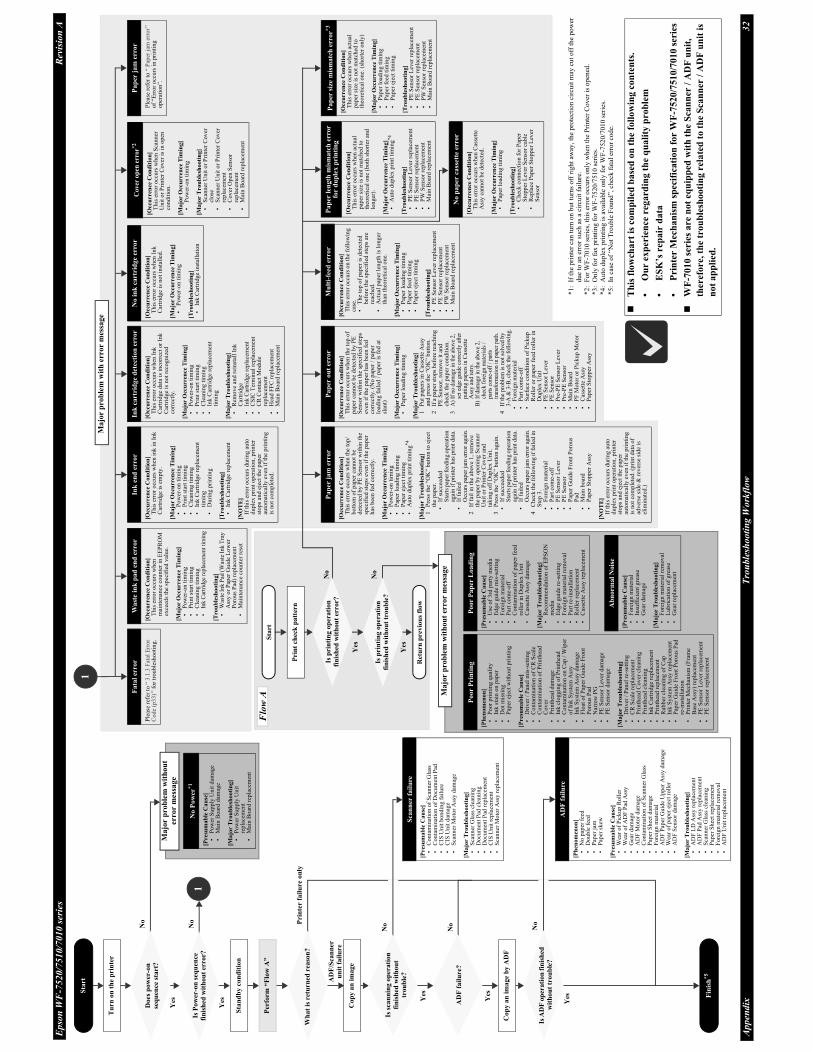
3.1.2 Troubleshooting Workflow
The following page describes the troubleshooting workflow. Follow the flow when troubleshooting problems.
Ink cartridge detection error
(non-Epson cartridge)Flash*2 --- --- ON*4
Ink cartridge is not recognized. Please replace the
cartridge.
<Ink Cartridges>XXXXXXX*5
No ink cartridge error Flash*2 --- --- ON*4The cartridge is installed incorrectly. Press it down
until it clicks.
<Ink Cartridges>XXXXXXX*5
Ink cartridge cover open
errorFlash*2 --- --- ---
The ink cartridge cover is open. Close the ink
cartridge cover.
Table 3-1. Error Message List
Status
WF-7010 series WF-7520/7510 series
LEDLCD Message
Power Network Paper Ink
Ep
son
WF
-752
0/7
51
0/7
010
ser
ies
Rev
isio
n A
Ap
pen
dix
Tro
uble
sho
oti
ng
Wo
rkfl
ow
32
Th
is f
low
chart
is c
om
pil
ed
base
d o
n t
he
foll
ow
ing c
on
ten
ts.
•O
ur
exp
eri
ence
reg
ard
ing t
he
qu
ali
ty p
rob
lem
•E
SK
’s r
epair
data
•P
rin
ter
Mec
han
ism
sp
ecif
icati
on
for
WF
-7520/7
510/7
010 s
erie
s
WF
-7010 s
eri
es a
re n
ot
eq
uip
ped
wit
h t
he
Sca
nn
er /
AD
F u
nit
,
ther
efore,
th
e tr
ou
ble
shooti
ng r
ela
ted
to
th
e S
ca
nn
er /
AD
F u
nit
is
no
t a
pp
lied
.
Fata
l er
ror
Ple
ase
refe
r to
“ 3
.1.3
Fat
al E
rro
r C
od
e (p
33
)” f
or
tro
ub
lesh
oo
tin
g.
Wa
ste
ink
pa
d e
nd
err
or
[Occu
rren
ce
Co
nd
itio
n]
Th
is e
rro
r o
ccu
rs w
hen
m
ain
ten
ance
co
un
ter
in E
EP
RO
M
exce
eds
the
spec
ifie
d v
alu
e.
[Ma
jor
Occu
rren
ce T
imin
g]
•P
ow
er-o
n t
imin
g•
Pri
nt
star
t ti
min
g•
Cle
anin
g t
imin
g•
Ink C
artr
idge
repla
cem
ent
tim
ing
[Tro
ub
lesh
oo
tin
g]
•W
aste
In
k P
ad (
Was
te I
nk
Tra
y
Ass
y o
r P
aper
Gu
ide
Lo
wer
P
oro
us
Pad
) re
pla
cem
ent
•M
ain
ten
ance
co
un
ter
rese
t
Ink
en
d e
rro
r
[Occu
rren
ce C
on
dit
ion
]T
his
err
or
occ
urs
wh
en i
nk
in
In
k
Car
trid
ge
is e
mp
ty.
[Ma
jor
Occu
rren
ce T
imin
g]
•P
ow
er-o
n t
imin
g•
Pri
nt
star
t ti
min
g•
Cle
anin
g t
imin
g•
Ink
Car
trid
ge
rep
lace
men
t ti
min
g•
Duri
ng p
rin
tin
g
[Tro
ub
lesh
oo
tin
g]
•In
k C
artr
idg
e re
pla
cem
ent
[NO
TE
]If
th
is e
rro
r o
ccu
rs d
uri
ng
au
to
du
ple
x p
rin
t o
per
atio
n,
pri
nte
r st
op
s an
d e
ject
th
e p
aper
au
tom
atic
ally
ev
en i
f th
e pri
nti
ng
is n
ot
com
ple
ted.
Ink
ca
rtri
dg
e d
etect
ion
erro
r
[Occ
urre
nce
Co
nd
itio
n]
Th
is e
rro
r o
ccu
rs w
hen
In
k
Car
trid
ge
dat
a is
in
corr
ect
or
Ink
C
artr
idg
e is
no
t re
cog
niz
ed
corr
ectl
y.
[Ma
jor O
ccu
rren
ce T
imin
g]
•P
ow
er-o
n t
imin
g•
Pri
nt
star
t ti
min
g•
Cle
anin
g t
imin
g•
Ink
Car
trid
ge
rep
lace
men
t ti
min
g
[Ma
jor
Tro
ub
lesh
oo
tin
g]
•R
emo
ve
and
rei
nst
all
Ink
C
artr
idg
e•
Ink
Car
trid
ge
rep
lace
men
t•
CS
IC T
erm
inal
rep
lace
men
t•
CR
Co
nta
ct M
od
ule
re
pla
cem
ent
•H
ead
FF
C r
epla
cem
ent
•M
ain
Bo
ard
rep
lace
men
t
No
in
k c
art
rid
ge
erro
r
[Occu
rren
ce C
on
dit
ion
]T
his
err
or
occ
urs
wh
en I
nk
C
artr
idg
e is
no
t in
stal
led
.
[Ma
jor O
ccu
rren
ce T
imin
g]
•P
ow
er-o
n t
imin
g
[Tro
ub
lesh
oo
tin
g]
•In
k C
artr
idg
e in
stal
lati
on
Cover
op
en e
rror*
2
[Occ
urre
nce
Co
nd
itio
n]
Th
is e
rro
r o
ccu
rs w
hen
Sca
nn
er
Un
it o
r P
rin
ter
Co
ver
is
in o
pen
co
ndit
ion.
[Ma
jor O
ccu
rre
nce
Tim
ing
]•
Po
wer
-on
tim
ing
[Ma
jor T
ro
ub
lesh
ooti
ng]
•S
can
ner
Un
it o
r P
rin
ter
Co
ver
cl
ose
•S
can
ner
Un
it o
r P
rin
ter
Co
ver
re
pla
cem
ent
•C
ov
er O
pen
Sen
sor
rep
lace
men
t•
Mai
n B
oar
d r
epla
cem
ent
Pa
per
ja
m e
rro
r
Ple
ase
refe
r to
“ P
aper
jam
err
or”
o
f “E
rro
r o
ccu
rs i
n p
rin
tin
g
oper
atio
n”.
Pap
er
jam
err
or
[Occu
rren
ce C
on
dit
ion
]T
his
err
or
occ
urs
wh
en t
he
top
/b
ott
om
of
pap
er c
ann
ot
be
det
ecte
d b
y P
E S
enso
r w
ith
in t
he
spec
ifie
d s
tep
s ev
en i
f th
e pap
er
has
bee
n f
ed c
orr
ectl
y.
[Ma
jor
Occu
rren
ce T
imin
g]
•P
ow
er-o
n t
imin
g•
Pap
er l
oad
ing
tim
ing
•P
aper
eje
ct t
imin
g•
Au
to d
up
lex
pri
nt
tim
ing
*4
[Ma
jor
Tro
ub
lesh
oo
tin
g]
1P
ress
the
“OK
” bu
tto
n t
o e
ject
th
e p
aper
.•
If s
ucc
eed
edS
tart
s pap
er fee
din
g o
per
atio
n
agai
n i
f pri
nte
r has
pri
nt
dat
a.•
If f
aile
dO
ccurs
pap
er jam
err
or
agai
n.
2If
fai
l in
th
e ab
ov
e 1
, re
mo
ve
the
pap
er b
y o
pen
ing
Sca
nn
er
Un
it o
r P
rin
ter
Cov
er a
nd
ta
kin
g o
ff D
up
lex
Un
it.
3P
ress
th
e “O
K”
bu
tto
n a
gai
n.
•If
su
ccee
ded
Sta
rts
pap
er fee
din
g o
per
atio
n
agai
n i
f pri
nte
r has
pri
nt
dat
a.•
If f
aile
dO
ccurs
pap
er jam
err
or
agai
n.
4C
hec
k th
e fo
llo
win
g if
fail
ed in
S
tep
3.
•F
ore
ign
mat
eria
l•
Par
t co
me-
off
•P
E S
enso
r L
ever
•P
E S
enso
r•
Pap
er G
uid
e F
ron
t P
oro
us
Pad
•M
ain
bo
ard
•P
aper
Sto
pp
er A
ssy
[NO
TE
]If
th
is e
rro
r o
ccu
rs d
uri
ng
au
to
du
ple
x p
rin
t o
per
atio
n,
pri
nte
r st
op
s an
d e
ject
th
e p
aper
au
tom
atic
ally
ev
en i
f th
e pri
nti
ng
is n
ot
com
ple
ted
. (p
rin
t d
ata
of
adv
erse
sid
e &
rev
erse
sid
e is
el
imin
ated
.)
Pap
er
ou
t er
ror
[Occ
urre
nce
Co
nd
itio
n]
Th
is e
rro
r o
ccu
rs w
hen
th
e to
p o
f p
aper
can
no
t b
e d
etec
ted
by
PE
S
enso
r w
ith
in t
he
spec
ifie
d s
tep
s ev
en i
f th
e p
aper
has
bee
n f
ed
corr
ectl
y.
(No
pap
er /
pap
er
load
ing
fai
led
/ p
aper
is
fed
at
slan
t)
[Ma
jor O
ccu
rren
ce T
imin
g]
•P
aper
lo
adin
g t
imin
g
[Ma
jor
Tro
ub
lesh
oo
tin
g]
1P
ut
pap
ers
in C
asse
tte
Ass
y
and
pre
ss t
he
“OK
” b
utt
on
.2
If a
pap
er s
top
s b
efo
re r
each
ing
P
E S
enso
r, r
emo
ve
it a
nd
ch
eck
th
e p
aper
co
nd
itio
n.
3A
)If
no d
amag
e in
the
above
2,
set
edge
guid
e co
rrec
tly a
fter
putt
ing p
aper
s in
Cas
sett
eA
ssy
and r
etry
.B
)If
dam
age
in t
he
above
2,
chec
k f
ore
ign m
ater
ials
/
par
ts c
om
e-off
/ p
arts
tran
sform
atio
n i
n p
aper
pat
h.
4If
the
pro
ble
m i
s not
solv
ed b
y
3-A
& 3
-B, ch
eck t
he
foll
ow
ing.
•F
ore
ign
mat
eria
l•
Par
t co
me-
off
•S
urf
ace
con
dit
ion
of
Pic
ku
p
Ro
ller
or
pap
er f
eed
ro
ller
in
D
up
lex
Un
it•
PE
Sen
sor
Lev
er•
PE
Sen
sor
•P
re-P
E S
enso
r L
ever
•P
re-P
E S
enso
r•
Mai
n B
oar
d•
PF
Mo
tor
or
Pic
kup
Mo
tor
•C
asse
tte
Ass
y•
Pap
er S
topper
Ass
y
Mu
lti-
feed
erro
r
[Occu
rren
ce C
on
dit
ion
]T
his
err
or
occ
urs
on
th
e fo
llo
win
g
case
.•
Th
e to
p o
f p
aper
is
det
ecte
d
bef
ore
th
e sp
ecif
ied
ste
ps
are
reac
hed
.•
Act
ual
pap
er l
eng
th i
s lo
ng
er
than
theo
reti
cal
on
e.
[Ma
jor
Occu
rren
ce T
imin
g]
•P
aper
lo
adin
g t
imin
g•
Pap
er f
eed
tim
ing
•P
aper
eje
ct t
imin
g
[Tro
ub
lesh
oo
tin
g]
•P
E S
enso
r L
ever
rep
lace
men
t•
PE
Sen
sor
rep
lace
men
t•
PW
Sen
sor
rep
lace
men
t•
Mai
n B
oar
d r
epla
cem
ent
Pa
per
len
gth
mis
ma
tch
err
or
for
du
ple
x p
rin
tin
g
[Occ
urr
en
ce C
on
dit
ion
]T
his
err
or
occ
urs
wh
en a
ctu
al
pap
er s
ize
is n
ot
mat
ched
to
theo
reti
cal
on
e (b
oth
sho
rter
an
d
lon
ger
).
[Ma
jor O
ccu
rren
ce T
imin
g]
•A
uto
duple
x p
rint
tim
ing
*4
[Tro
ub
lesh
oo
tin
g]
•P
E S
enso
r L
ever
rep
lace
men
t•
PE
Sen
sor
rep
lace
men
t•
PW
Sen
sor
rep
lace
men
t•
Mai
n B
oar
d r
epla
cem
ent
Pa
per
siz
e m
ism
atc
h e
rror
*3
[Occ
urr
en
ce C
on
dit
ion
]T
his
err
or
occ
urs
when
act
ual
p
aper
siz
e is
not
mat
ched
to
theo
reti
cal
on
e. (
sho
rter
on
ly)
[Ma
jor O
ccu
rren
ce T
imin
g]
•P
aper
lo
adin
g t
imin
g•
Pap
er f
eed
tim
ing
•P
aper
eje
ct t
imin
g
[Tro
ub
lesh
oo
tin
g]
•P
E S
enso
r L
ever
rep
lace
men
t•
PE
Sen
sor
rep
lace
men
t•
PW
Sen
sor
rep
lace
men
t•
Mai
n B
oar
d r
epla
cem
ent
No P
ow
er*1
[Presu
ma
ble
Ca
use
]•
Po
wer
Sup
ply
Unit
dam
age
•M
ain
Bo
ard
dam
age
[Ma
jor
Tro
ub
lesh
oo
tin
g]
•P
ow
er S
up
ply
Un
it
rep
lace
men
t•
Mai
n B
oar
d r
epla
cem
ent
Po
or P
rin
tin
g
[Ph
en
om
en
on
]•
Po
or
pri
nti
ng
qu
alit
y•
Ink
sta
in o
n p
aper
•D
ot
mis
sing
•P
aper
eje
ct w
itho
ut
pri
nti
ng
[Pre
sum
ab
le C
au
se]
•D
riv
er /
Pan
el m
is-s
etti
ng
•C
on
tam
inat
ion
of
CR
Sca
le•
Co
nta
min
atio
n o
f P
rin
thea
d
Co
ver
•P
rin
thea
d d
amag
e•
Ink
clo
gg
ing
of
Pri
nth
ead
•C
on
tam
inat
ion
on
Cap
/ W
iper
o
f In
k S
yst
em A
ssy
•In
k S
yst
em A
ssy
dam
age
•F
loat
of
Pap
er G
uid
e F
ron
t P
oro
us
Pad
•N
arro
w P
G•
PE
Sen
sor
Lev
er d
amag
e•
PE
Sen
sor
dam
age
[Ma
jor
Tro
ub
lesh
oo
tin
g]
•D
riv
er /
Pan
el r
e-se
ttin
g•
CR
Sca
le r
epla
cem
ent
•P
rin
thea
d C
ov
er c
lean
ing
•P
rin
thea
d c
lean
ing
•In
k C
artr
idg
e re
pla
cem
ent
•P
rin
thea
d r
epla
cem
ent
•R
ub
ber
cle
anin
g o
f C
ap•
Ink
Sy
stem
Ass
y r
epla
cem
ent
•P
aper
Gu
ide
Fro
nt
Po
rou
s P
ad
re-i
nst
alla
tio
n•
Pri
nte
r M
ech
anis
m (
Fra
me
Bas
e A
ssy
) re
pla
cem
ent
•P
E S
enso
r L
ever
rep
lace
men
t•
PE
Sen
sor
rep
lace
men
t
Po
or P
ap
er L
oad
ing
[Pres
um
ab
le C
au
se]
•U
se o
f 3
rd p
arty
med
ia•
Edg
e guid
e m
is-s
etti
ng
•F
ore
ign
mat
eria
l•
Par
t co
me-
off
•C
on
tam
inat
ion
of
pap
er f
eed
ro
ller
in
Du
ple
x U
nit
•C
asse
tte
Ass
y d
amag
e
[Ma
jor T
ro
ub
lesh
oo
tin
g]
•R
eco
mm
end
atio
n o
f E
PS
ON
m
edia
•E
dg
e g
uid
e re
-set
tin
g•
Fo
reig
n m
ater
ial
rem
ov
al•
Par
t re
-inst
alla
tio
n•
Ro
ller
rep
lace
men
t•
Cas
sett
e A
ssy r
epla
cem
ent
Ab
no
rma
l N
ois
e
[Pres
um
ab
le C
au
se]
•F
ore
ign
mat
eria
l•
Insu
ffic
ien
t g
reas
e•
Gea
r d
amag
e
[Ma
jor T
ro
ub
lesh
oo
tin
g]
•F
ore
ign
mat
eria
l re
mo
val
•
Lub
rica
tio
n o
f g
reas
e•
Gea
r re
pla
cem
ent
Sca
nn
er f
ail
ure
[Presu
ma
ble
Ca
use
]•
Co
nta
min
atio
n o
f S
can
ner
Gla
ss
•C
on
tam
inat
ion
of
Do
cum
ent
Pad
•
CIS
Un
it b
on
din
g f
ailu
re•
CIS
Un
it d
amag
e•
Sca
nn
er M
oto
r A
ssy
dam
age
[Ma
jor
Tro
ub
lesh
oo
tin
g]
•S
can
ner
Gla
ss c
lean
ing
•D
ocu
men
t P
ad c
lean
ing
•D
ocu
men
t P
ad r
epla
cem
ent
•C
IS U
nit
rep
lace
men
t•
Sca
nn
er M
oto
r A
ssy
rep
lace
men
t
AD
F f
ail
ure
[Ph
en
om
eno
n]
•N
o p
aper
fee
d•
Do
ub
le f
eed
•P
aper
jam
•P
aper
sk
ew
[Presu
ma
ble
Ca
use
]•
Wea
r o
f P
ick
up
Ro
ller
•W
ear
of
AD
F P
ad A
ssy
•G
ear
dam
age
•A
DF
Moto
r d
amag
e•
Co
nta
min
atio
n o
f S
can
ner
Gla
ss•
Pap
er S
hee
t d
amag
e•
Fo
reig
n m
ater
ial
•A
DF
Pap
er G
uid
e U
pp
er A
ssy d
amag
e•
Wea
r o
f p
aper
eje
ct r
oll
er•
AD
F S
enso
r d
amag
e
[Ma
jor
Tro
ub
lesh
oo
tin
g]
•A
DF
LD
Ass
y r
epla
cem
ent
•A
DF
Pad
Ass
y r
epla
cem
ent
•S
can
ner
Gla
ss c
lean
ing
•P
aper
Sh
eet
rep
lace
men
t•
Fo
reig
n m
ater
ial
rem
ov
al•
AD
F U
nit
rep
lace
men
t
Fin
ish
*5
Tu
rn o
n t
he
pri
nte
r
1
1
Majo
r p
rob
lem
wit
hou
t er
ror
mes
sage
Prin
t ch
eck
patt
ern
Wh
at
is r
etu
rned
rea
son
?
Co
py a
n i
mag
e
Co
py
an
im
ag
e b
y A
DF
Flo
w A
Ret
urn
pre
vio
us
flow
Is p
rin
tin
g o
pera
tion
fin
ish
ed
wit
hou
t tr
ou
ble
?
Sta
rt AD
F/S
can
ner
un
it f
ail
ure
Pri
nte
r fa
ilu
re o
nly
No
Yes
No
Yes
No
Yes
No
Yes
No
Yes
No
Sta
rt
Yes
*1
:If
th
e p
rin
ter
can
tu
rn o
n b
ut
turn
s o
ff r
igh
t aw
ay,
the
pro
tect
ion
cir
cuit
may
cu
t o
ff t
he
po
wer
d
ue
to a
n e
rror
such
as
a ci
rcu
it f
ailu
re.
*2
:F
or
WF
-70
10 s
erie
s, t
his
err
or
occ
urs
on
ly w
hen
th
e P
rin
ter
Co
ver
is
op
ened
.*3
:O
nly
fo
r fa
x p
rin
ting
for
WF
-75
20
/751
0 s
erie
s.*4
:A
uto
du
ple
x p
rin
ting
is
avai
lable
only
for
WF
-752
0/7
01
0 s
erie
s.*5
:In
cas
e o
f “N
ot
Tro
uble
Fo
un
d”,
chec
k f
atal
err
or
code.
Majo
r p
rob
lem
wit
h e
rror
mes
sage
Majo
r p
rob
lem
wit
hou
t er
ror
mes
sage
Is P
ow
er-o
n s
equ
ence
fin
ish
ed
wit
hou
t er
ror?
Per
form
“F
low
A”
Yes
No
Is A
DF
op
erati
on
fin
ish
ed
wit
ho
ut
tro
ub
le?
Sta
nd
by
con
dit
ion
AD
F f
ail
ure
?
Is s
can
nin
g o
per
ati
on
fin
ish
ed
wit
hou
t
trou
ble
?
Do
es
po
wer
-on
seq
uen
ce s
tart
?
No
pa
per
ca
sset
te e
rro
r
[Occ
urr
en
ce C
on
dit
ion
]T
his
err
or
occ
urs
when
Cas
sett
e A
ssy
can
not
be
det
ecte
d.
[Ma
jor O
ccu
rren
ce T
imin
g]
•P
aper
lo
adin
g t
imin
g
[Tro
ub
lesh
oo
tin
g]
•C
hec
k c
on
nec
tio
n f
or
Pap
er
Sto
pp
er L
ever
Sen
sor
cab
le•
Rep
lace
Pap
er S
top
per
Lev
er
Sen
sor
Is p
rin
tin
g o
per
ati
on
fin
ish
ed
wit
hou
t er
ror?

Troubleshooting 33
Epson WF-7520/7510/7010 series Revision A
3.1.3 Fatal Error Code
This section describes the fatal error code and the possible cause for this product.
Printer fatal error list
Table 3-2. Fatal Error List (Printer)
Error typeError
codeError name Possible cause
DC motor
error
01H CR PID excess load error
• CR Encoder failure (contaminated/detached scale, Encoder Board failure)
• CR Motor failure
• Carriage overload error (paper jam/foreign object)
• Cable disconnection
02H CR PID excess speed error
• CR Encoder failure (contaminated/detached scale, Encoder Board failure)
• Motor driver failure (Main Board failure)
• Tooth skip of the CR Timing Belt
• Improper tension of the CR Timing Belt
03H CR PID reverse error
• CR Encoder failure (contaminated/detached scale, Encoder Board failure)
• Tooth skip of the CR Timing Belt
• Improper tension of the CR Timing Belt
• Paper jam
04H CR PID lock error
• CR Encoder failure (contaminated/detached scale, Encoder Board failure)
• CR Motor failure
• Carriage overload error (paper jam/foreign object)
• Cable disconnection
05H CR PID speed degradation error
• CR Encoder failure (contaminated/detached scale, Encoder Board failure)
• Motor driver failure (Main Board failure)
• Tooth skip of the CR Timing Belt
• Improper tension of the CR Timing Belt
• Paper jam
08H CR load position reverse error
• CR Encoder failure (contaminated/detached scale, Encoder Board failure)
• Tooth skip of the CR Timing Belt
• Improper tension of the CR Timing Belt
• Paper jam
09H CR load position excess speed error
• CR Encoder failure (contaminated/detached scale, Encoder Board failure)
• Motor driver failure (Main Board failure)
• Tooth skip of the CR Timing Belt
• Improper tension of the CR Timing Belt
0AH CR load position excess load error
• CR Encoder failure (contaminated/detached scale, Encoder Board failure)
• CR Motor failure
• Carriage overload error (paper jam/foreign object)
• Cable disconnection
F1H PF PID excess load error
• PF Encoder failure (contaminated/detached scale, Encoder Board failure)
• PF Motor failure
• PF drive mechanism overload (paper jam/foreign object)
• Cable disconnection
F2H PF PID excess speed error
• PF Encoder failure (contaminated/detached scale, Encoder Board failure)
• Motor driver failure (Main Board failure)
• Tooth skip of the PF Timing Belt
• Improper tension of the PF Timing Belt
F3H PF PID reverse error
• PF Encoder failure (contaminated/detached scale, Encoder Board failure)
• Tooth skip of the PF Timing Belt
• Improper tension of the PF Timing Belt
• Paper jam
F4H PF PID lock error
• PF Encoder failure (contaminated/detached scale, Encoder Board failure)
• PF Motor failure
• PF drive mechanism overload (paper jam/foreign object)
• Cable disconnection
F6H PF PID excess torque limitation error • PF drive mechanism overload (paper jam/foreign object)

Troubleshooting 34
Epson WF-7520/7510/7010 series Revision A
DC motor
error
F8H PF load position reverse error
• PF Encoder failure (contaminated/detached scale, Encoder Board failure)
• Tooth skip of the PF Timing Belt
• Improper tension of the PF Timing Belt
F9H PF load position excess speed error
• PF Encoder failure (contaminated/detached scale, Encoder Board failure)
• Motor driver failure (Main Board failure)
• Tooth skip of the PF Timing Belt
• Improper tension of the PF Timing Belt
FAH PF load position excess load error • PF Encoder failure (contaminated/detached scale, Encoder Board failure)
• PF Motor failure
• PF drive mechanism overload (paper jam/foreign object)
• Cable disconnectionFCH PF load position error
11H ASF PID excess load error*
• Pickup Encoder failure (contaminated/detached scale, Encoder Board
failure)
• Pickup Motor failure
• Pickup drive mechanism (2nd cassette) overload (paper jam/foreign object)
• Cable disconnection
12H ASF PID excess speed error*
• Pickup Encoder failure (contaminated/detached scale, Encoder Board
failure)
• Pickup Motor driver failure (Main Board failure)
13H ASF PID reverse error*
• Pickup Encoder failure (contaminated/detached scale, Encoder Board
failure)
• Paper jam
14H ASF PID lock error*
• Pickup Encoder failure (contaminated/detached scale, Encoder Board
failure)
• Pickup Motor failure
• Pickup drive mechanism (2nd cassette) overload (paper jam/foreign object)
• Cable disconnection
16H ASF PID excess torque limitation error* • Pickup Roller (2nd cassette) overload (paper jam/foreign object)
18H ASF load position reverse error*
• Pickup Encoder failure (contaminated/detached scale, Encoder Board
failure)
• Paper jam
19H ASF load position excess speed error*
• Pickup Encoder failure (contaminated/detached scale, Encoder Board
failure)
• Motor driver failure (Main Board failure)
1AH ASF load position excess load error*
• Pickup Encoder failure (contaminated/detached scale, Encoder Board
failure)
• Pickup Motor failure
• Pickup drive mechanism (2nd cassette) overload (paper jam/foreign
object)
• Cable disconnection
Motor drive
time error
D1H CR (PID) driving time error
• Main Board failure
D2H CR (load position) driving time error
D3H PF (PID) driving time error
D4H PF (BS) driving time error
D5H ASF (PID) driving time error*
D6H ASF (BS) driving time error*
Printhead
system error
40H Transistor temperature error • Main Board failure
41H X-Hot detect error (pre printing)
• Printhead failure
• Main Board failure42H X-Hot detect error (after flushing)
43H Head temperature error
Table 3-2. Fatal Error List (Printer)
Error typeError
codeError name Possible cause

Troubleshooting 35
Epson WF-7520/7510/7010 series Revision A
Note *: WF-7520/7010 series only
Sequence
error
50H Home position error
• Paper jam
• Foreign object
• Deformation of the Main Frame
51H Deadlock avoidance error
52H Impossible contact detection error
56HContact error at ink replacement timing
(Power-off)
5BH Insoluble paper jam error• Paper jam
• Foreign object
Sensor error
60H PW detector error• PW Sensor failure
• Main Board failure
61H PW detector confusion error
• PW Sensor failure
• Main Board failure
• A piece of paper remaining
• Ink contamination on the Paper Guide Front Assy
63H PE detector error• PE Sensor failure
• Main Board failure
Ink device
error
B0H -
CFHInk device error
• Ink Cartridge failure
• CSIC Terminal failure
• CR Contact Module failure
• Main Board failure
Circuit error 80H Circuit error (include blowout of a fuse) • Main Board failure
Table 3-2. Fatal Error List (Printer)
Error typeError
codeError name Possible cause

Troubleshooting 36
Epson WF-7520/7510/7010 series Revision A
Scanner/ADF fatal error list (WF-7520/7510 series only)
Table 3-3. Fatal Error List (Scanner/ADF)
Error code Error name Possible cause
01H ADF PID excess speed error• ADF Encoder failure (contaminated/detached scale, Encoder Board failure)
• Motor driver failure (Main Board failure)
02H ADF PID reverse error• ADF Encoder failure (contaminated/detached scale, Encoder Board failure)
• Paper jam
03H ADF PID lock error • ADF Encoder failure (contaminated/detached scale, Encoder Board failure)
• ADF Motor failure
• ADF drive overload (paper jam/foreign object)
• Cable disconnection
04H ADF PID acceleration lock detection error
05H ADF PID excess load error
06H ADF PID driving time error • Main Board failure
09H ADF BS+ excess speed error• ADF Encoder failure (contaminated/detached scale, Encoder Board failure)
• Motor driver failure (Main Board failure)
0AH ADF BS+ reverse error• ADF Encoder failure (contaminated/detached scale, Encoder Board failure)
• Paper jam
0BH ADF BS+ lock error • ADF Encoder failure (contaminated/detached scale, Encoder Board failure)
• ADF Motor failure
• ADF drive overload (paper jam/foreign object)
• Cable disconnection0DH ADF BS+ excess load error
0EH ADF BS+ driving time error • Main Board failure
10H Scanner HP detection error
• CIS Unit failure
• Scanner Housing failure
• Main Board failure
20H Scanner LED light error• CIS Unit failure
• Main Board failure
30H ADF option error • Main Board failure
36H ADF paper jam error • Paper jam

Troubleshooting 37
Epson WF-7520/7510/7010 series Revision A
3.1.4 FAX Troubleshooting (WF-7520/7510 series only)
3.1.4.1 FAX Log
When an error related to fax occurs, it is not only indicated on the LCD but also saved as a log file. The error
code is recorded in it, and according to this log, the contents of the error can be confirmed.
Note *1: The latest communication log for all destinations are printed in a list form when the sequential broadcast is executed. Cancellation is treated as
a normal termination, therefore, if it is cancelled, the latest log is printed when the auto print setting is “always print”, and not printed when the
setting is “only when an error occurs”. If “only when an error occurs” is selected, the log is printed even when an error occurs for just one
destination.
*2: The power failure log when the sequential broadcast is being executed is not printed for the destinations to which the transmission log is already
complete then. If the power failure occurs before the scheduled sending time when a broadcast is scheduled, the scheduled sending time is
recorded.
Table 3-4. FAX Log (1)
Log Name Description Save Destination
Latest log*1
(Last Transaction) The latest communication log of sending / polling reception Nonvolatile memory
Communication log
(Fax Log)
The following information is stored.
Note *: For error codes, see Table 3-6. Error Code List (p.38).
Nonvolatile memory
Power failure log*2
(Fax Log)
The information stored in this log is the same as the communication log. However, since the
airtime is “Unknown” in this case, the result of it is recorded as “power failure”.Nonvolatile memory
The communication log is not stored under the following conditions:
When the sending operation is canceled while storing B&W image or waiting for
redialing.
In the case of a power failure during the operation of sending/polling reception including
waiting status for redial, or during receive operation.
When the receiving operation is canceled before the fax signal is detected.
If the fax signal is not detected during receiving operation.
If cancelled during the sequential broadcast.
(The log for the destinations of “not dialed yet” or “waiting for re-dial” is not saved except
for those of which the communication is complete.)
Item Information
Communication start
date / timeYear/month/day/hour/minute
Communication type Sending/receiving/polling reception
Communication ID
Sending/polling reception:
• Destination name of speed dial (first 20 characters)
• Telephone number (last 20 characters)
• Destination fax ID (20 characters)
Receiving:
• Destination fax ID (20 characters)
Airtime Hour/minute/second
Communication pages 0 to 100
Communication result
Common:
Normal/cancel/error code*
Sending/polling reception:
No dial tone detected/No fax signal detected/Busy tone detected

Troubleshooting 38
Epson WF-7520/7510/7010 series Revision A
Error codes
Table 3-5. FAX Log (2)
Log Name Description Save Destination
Protocol trace
The following information of the latest communication is stored.
Note *: If a large amount of FIF is received, the recorded command/response may be less than
40.
Volatile memory
Table 3-6. Error Code List
Error
Code
(HEX)
Phenomenon LCD Display Print Example
000 Successful completion (Monochrome) Complete OK
C000 Successful completion (Color) Complete OK Color
400 Communication error Communication error Error code
401 Communication error Communication error Error code
402 Communication error Communication error Error code
403 Communication error Communication error Error code
404 Communication error Communication error Error code
405 Communication error Communication error Error code
407 Communication error Communication error Error code
408 Communication error Communication error Error code
409 Communication error Communication error Error code
410 Communication error Communication error Error code
412 Communication error Communication error Error code
416 Communication error Communication error Error code
417 Communication error Communication error Error code
418 Communication error Communication error Error code
420Fax signal was not detected during receive operation. (The call was a
telephone call)Not displayed ---
421 Communication error Communication error Error code
422 Communication error Communication error Error code
427 Communication error Communication error Error code
433 Communication error Communication error Error code
Item Information
Communication start
date / timeYear/month/day/hour/minute
Communication type Sending/receiving/polling reception
Communication ID
Sending/polling reception:
• Destination name of speed dial (first 20 characters)
• Telephone number (last 20 characters)
• Destination fax ID (20 characters)
Receiving:
• Destination fax ID (20 characters)
Airtime Hour/minute/second
Communication pages 0 to 100
Communication result
Common:
Normal/cancel/error code
Sending/polling reception:
No dial tone detected/No fax signal detected/Busy tone detected
Diagnosing code 10 bytes
Protocol data
The latest 43 commands/responses*
• Time stamp
• Sending / receiving
• Command /response code
(See Table 3-7. Command/Response Code (p.40))
• FCF/FIF (first 33 octets).

Troubleshooting 39
Epson WF-7520/7510/7010 series Revision A
434 Communication error Communication error Error code
436 Communication error Communication error Error code
459 Communication error Communication error Error code
490 Communication error Communication error Error code
494 Communication error Communication error Error code
495 Communication error Communication error Error code
496 Communication error Communication error Error code
501 Communication error Communication error Error code
502 Communication error Communication error Error code
503 Communication error Communication error Error code
504 Communication error Communication error Error code
505 Communication error Communication error Error code
540 Communication error Communication error Error code
541 Communication error Communication error Error code
542 Communication error Communication error Error code
543 Communication error Communication error Error code
544 Communication error Communication error Error code
550 Communication error Communication error Error code
554 Communication error Communication error Error code
620 Communication error Communication error Error code
621 Communication error Communication error Error code
623 Communication error Communication error Error code
624 Communication error Communication error Error code
630 A busy tone was detected after dialingTalking
(Line Busy)
Talking
(Line Busy)
631 Communication error Communication error Error code
632 Communication error Communication error Error code
633 Communication error Communication error Error code
634 A fax signal was not detected for a given length of time after dialing No Answer No Answer
637 A dial tone was not detected before dialing No Dial Tone No Dial Tone
638 A power failure occurred during communication Not displayed Power Fail
700 The communication was canceled by an operation Canceled Canceled
706 System error System Error Error code
709 Communication error Communication error Error code
815 Communication error Communication error Error code
870 The image memory is full Memory Full Memory Full
871 The maximum number of files was exceeded Error code Error code
873 Communication error Communication error Error code
874 Communication error Communication error Error code
875 Communication error Communication error Error code
880 System error System Error Error code
881 System error System Error Error code
882 System error System Error Error code
883 System error System Error Error code
884 System error System Error Error code
928 Collision (A call signal was detected when shifting to dial operation) Not displayed ---
F0B Communication error Communication error Error code
F1E Communication error Communication error Error code
F20 Communication error Communication error Error code
F21 System error System Error Error code
Table 3-6. Error Code List
Error
Code
(HEX)
Phenomenon LCD Display Print Example

Troubleshooting 40
Epson WF-7520/7510/7010 series Revision A
Note *: Confirm the fatal error code with the Adjustment Program to check which error occurred. (See " 3.1.3 Fatal Error Code (p33)".)
Command/response code
F23 Communication error Communication error Error code
F24 Communication error Communication error Error code
F25 Communication error Communication error Error code
F27 System error System Error Error code
F28 System error System Error Error code
F29 Communication error Communication error Error code
F2A Communication error Communication error Error code
F2B No image data for reprint exists No Image ---
F2F System error System Error Error code
F3A Communication error Communication error Error code
F51 System error System Error Error code
F57 Communication error Communication error Error code
F58 Communication error Communication error Error code
F59 System error System Error Error code
F60 A scanner fatal error occursSame message when a scanner
fatal error occurred* Error code
F61 A printer fatal error occursSame message when a printer
fatal error occurred* Error code
F62 Reserved --- Error code
F63 ADF misfeed or paper jam occurredSame message when an ADF
fatal error occurred* ADF Jam
F64 The memory for printing received image is full Error code Error code
Table 3-7. Command/Response Code
Command/response
code
FCF value (HEX)
(LSB first: X=0) Content
First Second
DIS 80 - Digital Identification Signal
CSI 40 - Called Subscriber Identification
NSF 20 - Non-Standard Facilities
DTC 81 - Digital Transmit Command
CIG 41 - CallInG subscriber identification
NSC 21 - Non-Standard facilities Command
PWD C1 - PassWorD
SEP A1 - Selective Polling
Reserved (PSA) 61 - Polled SubAddress
Reserved (CIA) E1 - Calling subscriber Internet Address
Reserved (ISP) 11 - Internet Selective Polling address
DCS 82 - Digital Command Signal
TSI 42 - Transmitting Subscriber Identification
NSS 22 - Non-Standard facilities Set-up
SUB C2 - SUBaddress
SID A2 - Sender IDentification
TRN E6 - Training
TCF F0 - Training Check
CTC 12 - Continue To Correct
Reserved (TSA) 62 - Transmitting Subscriber internet Address
Reserved (IRA) E2 - Internet Routing Address
CFR 84 - ConFirmation to Receive
Table 3-6. Error Code List
Error
Code
(HEX)
Phenomenon LCD Display Print Example

Troubleshooting 41
Epson WF-7520/7510/7010 series Revision A
FTT 44 - Failure To Train
CTR C4 - Response for Continue To correct
Reserved (CSA) 24 - Called Subscriber internet Address
EOM 8E - End Of Message
MPS 4E - MultiPage Signal
EOP 2E - End Of Procedure
PRI-EOM 9E - Procedure Interrupt-End Of Message
PRI-MPS 5E - Procedure Interrupt-MultiPage Signal
PRI-EOP 3E - Procedure Interrupt-End Of Procedure
Reserved (EOS) 1E - End Of Selection
PPS-EOM BE 8E Partial Page Signal-End Of Message
PPS-MPS BE 4E Partial Page Signal-MultiPage Signal
PPS-EOP BE 2E Partial Page Signal-End Of Procedure
PPS-PRI-EOM BE 9E Partial Page Signal-Procedure Interrupt- End Of Message
PPS-PRI-MPS BE 5E Partial Page Signal-Procedure Interrupt- MultiPage Signal
PPS-PRI-EOP BE 3E Partial Page Signal-Procedure Interrupt- End Of Procedure
PPS-EOS BE 1E Partial Page Signal-End Of Selection
PPS-NULL BE 00 Partial Page Signal-partial page boundary
EOR-EOM CE 8E End Of Retransmission-End Of Message
EOR-MPS CE 4E End Of Retransmission-MultiPage Signal
EOR-EOP CE 2E End Of Retransmission-End Of Procedure
EOR-PRI-EOM CE 9E End Of Retransmission-Procedure Interrupt-End Of Message
EOR-PRI-MPS CE 5E End Of Retransmission-Procedure Interrupt-MultiPage Signal
EOR-PRI-EOP CE 3E End Of Retransmission-Procedure Interrupt-End Of Procedure
EOR-EOS CE 1E End Of Retransmission-End Of Selection
EOR-NULL CE 00 End Of Retransmission- partial page boundary
RR 6E - Receive Ready
MCF 8C - Message ConFirmation
RTP CC - ReTrain Positive
RTN 4C - ReTrain Negative
PIP AC - Procedure Interrupt Positive
PIN 2C - Procedure Interrupt Negative
PPR BC - Partial Page Request
RNR EC - Receive Not Ready
ERR 1C - Response for End of Retransmission
Reserved (FDM) FC - File Diagnostic Message
DCN FA - DisCoNnect
CRP 1A - Command RePeat
Reserved (FNV) CA - Field Not Valid
PIX FF - PIXel image
Space Other combinations Unknown command/response
Table 3-7. Command/Response Code
Command/response
code
FCF value (HEX)
(LSB first: X=0) Content
First Second

Troubleshooting 42
Epson WF-7520/7510/7010 series Revision A
3.1.4.2 Error Code/Superficial Phenomenon-Based Troubleshooting
This section explains the troubleshooting procedures based on the error codes and superficial phenomenon.
When an error occurs, it may be displayed on the LCD panel with a message instead of
an error code. To check the error code, print out a fax log.
If the problem is not solved even after carrying out the remedy shown in the Table 3-8,
print out a protocol trace to analyze the cause of the error.
Table 3-8. Troubleshooting Based on the Error Code/Superficial Phenomenon
Error code (LCD
Message)/PhenomenonDescription Remedy
Communication Error
(The error is indicated with
error code on the fax log.)
Communication error
Turn off v.34 and try again.
Turn off ECM and try again.
When using xDSL, check the connection from “Line” jack to the fax
via the xDSL splitter.
When using TAM, check the connection from “Line” jack to the
TAM via the fax.
Check if the telephone line makes any sounds.
Line Busy The line is busy. Try again later.
No answer
The other end of the line does not
answer.
Check the number and dial again.The other end of the line
answered but no answer tone is
detected.
Power fail
Power failure occurred during
sending/receiving/printing/
redialing.
Confirm the P/S Board Connector Cable or P/S Board is not
damaged, and retry.
706,880-884,F21,F27-
F28,F2F,F51,F59
A system error (fax circuit failure)
occursReplace the FAX board with a new one.
Memory full Out of Memory
Ask the sender to resend the fax in several batches.871
Maximum number of files is
exceeded
F60 A scanner fatal error occurred • See Table 3-2 "Fatal Error List (Printer)" (p.33).
• See Table 3-3 "Fatal Error List (Scanner/ADF)" (p.36).F61 A printer fatal error occurred
F62 Reserved ---
F63ADF document mis-feed or paper
jam occurs
• Set the documents and try again.
• If a paper jam error occurs, remove the jammed paper and try
again.
F64The memory for printing received
image is fullAsk the sender to resend the fax in several batches.
Cannot receive faxes
The telephone cable is not
connected properly.Connect the telephone cable properly.
The telephone line is not working. Verify if the phone line works by connecting to a phone to it.
Auto answer is set to “N”. Set to “Y”.
DRD setting is incorrect.Set the setting to “ALL” and try again. Should other ring patterns be
selected, contact the telephone company.
Calling signal cannot be detected.Contact the telephone company or obtain the fax log for more
analysis.
Cannot dial
The telephone cable is not
connected properly. Connect the telephone cable properly.
The telephone line is not working. Verify if the phone line works by connecting to a phone to it.
Pulse/Tone dial setting error Turn the setting to the other one and try again.
Cannot receive/send faxes
in color
ECM is set to off. Set to on and try again.
Fax mode is set to “B&W only”. Set to “B&W/Color”.

Troubleshooting 43
Epson WF-7520/7510/7010 series Revision A
Cannot print all the
received data when
printing data stored in
memory
The size of the memory is 2.0
Mbyte. If the data becomes over
the set threshold, oldest data are
deleted to make room for new
ones.
Ask the sender to resend the data if necessary because the data
deleted from the memory can not be restored.
Images run off the paper
Auto reduction is set to off. Set auto reduction to on and reprint the data.
Paper size setting does not match
the size of the received data.Choose the correct setting and reprint the data.
Paper size setting does not match
the size of papers in the tray.
Choose the correct setting or load correct sized papers in the tray and
reprint the data.
Table 3-8. Troubleshooting Based on the Error Code/Superficial Phenomenon
Error code (LCD
Message)/PhenomenonDescription Remedy

CHAPTER 4
DISASSEMBLY/REASSEMBLY

Disassembly/Reassembly Overview 45
Epson WF-7520/7510/7010 series Revision A
4.1 Overview
This chapter describes procedures for disassembling the main parts/units of WF-7520/7510/7010 series. Unless
otherwise specified, disassembled parts/units can be reassembled by reversing the disassembly procedure. See
the cautions or tips for disassembly/reassembly described in "4.3 Detailed Disassembly/Reassembly Procedure
for each Part/Unit (p55)".
Read the "Safety Precautions (p3)" before disassembling and reassembling.
When you have to remove units or parts that are not described in this chapter, see the exploded diagrams of SPI
(Service Parts Information).
4.1.1 Tools
Use only specified tools to avoid damaging the printer.
Note 1: Some of the tools listed above are commercially available.
2: EPSON provides the tools listed with EPSON part code.
4.1.2 Jigs
In this chapter, the product names are called as follows:
WF-7520 series: Epson WF-7525/Epson WF-7521/Epson WF-7520
WF-7510 series: Epson WF-7515/Epson WF-7511/Epson WF-7510
WF-7010 series: Epson WF-7018/Epson WF-7015/Epson WF-7012/Epson WF-7011/
Epson WF-7010
Name Availability EPSON Part Code
(+) Phillips screwdriver #1 O 1080530
(+) Phillips screwdriver #2 O ---
Flathead screwdriver O ---
Flathead Precision screwdriver #1 O ---
Tweezers O ---
Longnose pliers O ---
Acetate tape --- 1003963
Nippers O ---
Name Quantity EPSON Part Code
Thickness gauge (1.5 mm) 2 Commercially available
Thickness gauge (1.9 mm) 2 Commercially available
Sonic tension gauge 1 1294120

Disassembly/Reassembly Disassembly/Reassembly Procedures 46
Epson WF-7520/7510/7010 series Revision A
4.2 Disassembly/Reassembly Procedures
4.2.1 Parts/Units Need to be Removed in Advance
In "4.2.2 Disassembling Flowchart (p48)", the procedures are indicated on the premise that some parts/units are
removed in advance. Make sure to remove the following parts/units before starting disassembly.
Cassette Assy 1st / 2nd
Figure 4-1. Removing the Cassette Assy 1st/2nd
Duplex Unit
Figure 4-2. Removing the Duplex Unit

Disassembly/Reassembly Disassembly/Reassembly Procedures 47
Epson WF-7520/7510/7010 series Revision A
This section describes procedures for disassembling the parts/units in a flowchart format. For some parts/units,
detailed procedures or precautions are provided (accordingly indicated by icons and cell's color). Refer to the
explanations in the example chart below and perform an appropriate disassembling and assembling procedure.
(See "4.3 Detailed Disassembly/Reassembly Procedure for each Part/Unit (p55)".)
For routing cables, see "4.4 Routing FFCs/cables (p63)".
The example below shows how to see the charts on the following pages.
USB Cover
1
2
(p 15) (p 20)
S3
Ink System Assy
1
1
(p 16) (p 40)
S4
Item Description Reference
Parts/unit nameWhite-letter Part/unit supplied as an ASP ---
Black-letter Part/unit not supplied as an ASP ---
Icon
Indicates a practice or condition that could result in
injury or loss of life if not strictly observed.
Indicates the reference
page in blue-letter
Indicates a practice or condition that could result in
damage to, or destruction of equipment if not strictly
observed.
Indicates the reference
page in blue-letter
Indicates the parts that are inevitably broken in the
disassembling procedure, and should be replaced with
a new one for reassembly.
Indicates the reference
page in blue-letter
Indicates necessary check items in the disassembling/
assembling procedure.
Indicates the reference
page in blue-letter
Indicates supplementary explanation for disassembly
is given.
Indicates the reference
page in blue-letter
Indicates particular tasks to keep quality of the units
are required.
Indicates the reference
page in blue-letter
Indicates particular routing of cables is required.Indicates the reference
page in blue-letter
Indicates particular adjustment(s) is/are required.Chapter 5 "Adjustment
(p68)"
Indicates lubrication is required.Chapter 6 "Maintenance
(p79)"
Indicates the number of screws securing the parts/
units.---
Indicates the points secured with other than a screw
such as a hook, rib, dowel or the like.---
Shows removal/installation as a unit/assy. is available.
Reference page
Shows the screw types and the specified torque in the “Screw type/torque list”.
White letters indicate a part/unit supplied as an ASP.
Black letters indicate a part/unit not supplied as an ASP.

Ep
son
WF
-752
0/7
51
0/7
010
ser
ies
Rev
isio
n A
Dis
ass
embly
/Rea
ssem
bly
Dis
ass
em
bli
ng
Flo
wch
art
48
4.2
.2D
isa
ssem
bli
ng
Flo
wch
art
4.2
.2.1
Exte
rior
Part
s
Flo
wch
art
4-1
.D
isa
ssem
bli
ng
Flo
wch
art
(1
)
WF
-7520 s
erie
s
Scr
ew t
yp
e/to
rqu
e li
st
Sy
mb
ol
Scre
w t
yp
eT
orq
ue
C.B
.P-T
ITE
SC
RE
W 3
x1
0 F
/ZB
-3C
6 ±
1 k
gf·
cm
C.B
.P-T
ITE
SC
RE
W 3
x1
0 F
/ZN
-3C
6 ±
1 k
gf·
cm
C.B
.P-T
ITE
SC
RE
W 3
x8
F/Z
N-3
C6
± 1
kgf·
cm
C.B
.P-T
ITE
SC
RE
W 2
x8
F/Z
N-3
C2
± 0
.5 k
gf·
cm
C.B
.P-T
ITE
SC
RE
W 2
.5x8
F/Z
N-3
C4
± 1
kgf·
cm
C.B
.P-T
ITE
SC
RE
W 3
x1
0 F
/ZN
-3C
8 ±
1 k
gf·
cm
C.B
.P-T
ITE
SC
RE
W 3
x8
F/Z
N-3
C8
± 1
kgf·
cm
C.B
.P-T
ITE
(S
-P1)
SC
RE
W 3
x12
F/Z
N-3
C5
.5 ±
0.5
kg
f·cm
C.B
.S-T
ITE
SC
RE
W 3
x6
F/Z
N-3
C6
± 1
kgf·
cm
C.B
.S-T
ITE
SC
RE
W 3
x1
0 F
/ZN
-3C
6 ±
1 k
gf·
cm
C.P
.SC
RE
W 2
.5x
6 F
/ZN
-3C
2 ±
0.5
kg
f·cm
C.P
.SC
RE
W 3
x4
F/Z
N-3
C2
± 0
.5 k
gf·
cm
C.P
.SC
RE
W 3
x6
F/Z
N-3
C6
± 1
kgf·
cm
C.B
.P-T
ITE
(S
-P1)
SC
RE
W 3
x12
F/Z
N-3
C6
± 1
kgf·
cm
C.P
.SC
RE
W 3
x4
F/Z
N-3
C6
± 1
kgf·
cm
C.B
.S-T
ITE
SC
RE
W 3
x6
F/Z
B-3
C6
± 1
kgf·
cm
C.B
.P-T
ITE
SC
RE
W 3
x8
F/Z
N-3
C5
.5 ±
0.5
kg
f·cm
C.B
.P-T
ITE
SC
RE
W 2
.6x5
F/Z
N-3
C2
± 0
.5 k
gf·
cm
C.B
.P-T
ITE
SC
RE
W 3
x6
F/Z
N-3
C6
± 1
kgf·
cm
C.B
.P-T
ITE
SC
RE
W 3
x8
F/Z
N-3
C5
± 1
kgf·
cm
S1
S2
S3
S4
S5
S6
S7
S8
S9
S1
0
S1
1
S1
2
S1
3
S1
4
S1
5
S1
6
S1
7
S1
8
S1
9
S2
0
Foot
---
---
---
Pap
er S
top
per
A
ssy
2n
d
2 ---
(p 5
9)
(p
79
)
S7
Wast
e In
k T
ray
Cover
1 2
(p 5
5)
S1
Pic
ku
p A
ssy
2n
d
1 2
(p 5
5)
S2
Pap
er S
top
per
A
ssy 2
nd
A
(p 4
9)
Low
er C
ase
6 4
(
p 5
6)
S2
Wa
ste
Ink
Tra
y
Ass
y
1 4
(
p 5
5)
(p
68)
S1
WF
-7510 s
erie
s
Foot
---
---
---
A
(p 4
9)
Low
er C
ase
6 4
(
p 5
6)
S2
Wa
ste
Ink
Tra
y
Ass
y
1 4
(
p 5
5)
(p
68)
S1
Pap
er S
top
per
A
ssy
1st
2 ---
(p 5
9)
(p
79
)
S3
Co
mm
on
pa
rts/
un
it
WF
-75
20
/701
0 s
erie
s sp
ecif
ic
pa
rts/
un
it

Ep
son
WF
-752
0/7
51
0/7
010
ser
ies
Rev
isio
n A
Dis
ass
embly
/Rea
ssem
bly
Dis
ass
em
bli
ng
Flo
wch
art
49
Flo
wch
art
4-2
.D
isa
ssem
bli
ng
Flo
wch
art
(2
)
Pa
nel
Bo
ard
4 4
(
p 5
6)
S2
LC
D U
nit
2 2
(
p 5
6)
S4
Pan
el
Ho
usi
ng
U
pp
er A
ssy
---
---
(p 6
2)
Pan
el U
nit
3 5
(
p 5
6)
(p
63)
S2
Pan
el G
ear
/ P
an
el L
ever
--- 4
---
B
Dec
ora
tion
Pla
te
Hou
sin
g R
igh
t
Hou
sin
g L
eft
(p 5
2)
AD
F U
nit
/S
can
ner
Un
it
4 ---
(p 6
4)
S1
4
Pap
er S
heet
H
old
er
--- 3
---
Hin
ge
2 ---
---S2
US
B C
ov
er
2 7
(p
55
)
S1
Co
ver
Op
en
Sen
sor
--- 2
(p 6
3)
Ho
usi
ng
Up
per
---
---
---
Hou
sin
g U
pp
er
Ass
y (
w/
Pan
el
Un
it)
4 ---
(p 5
5)
(p
63
)
S2
Pa
per
Sh
eet
--- 2
---
Ferr
ite C
ore
---
---
---
AD
F P
ad
Ass
y
--- 4
(p 5
7)
Docu
men
t P
ad
---
---
(p 5
6)
(p 4
8)
AD
F C
over
4 ---
(p 5
8)
S3
LD
Sh
aft
--- 1
(p 7
9)
AD
F L
D A
ssy
--- 2
(p 5
8)
Exte
nsi
on
Sp
rin
g
1.6
9
--- 2
---
Dec
ora
tion
Pla
te
6 2
---S2
S1
Ho
usi
ng
Rig
ht
---
18
(
p 5
5)
Ho
usi
ng
Lef
t
---
19
(
p 5
5)
A
1
Pan
el U
nit
(p 5
0)
Scr
ew t
yp
e/to
rque
list
Sy
mb
ol
Scre
w t
yp
eT
orq
ue
C.B
.P-T
ITE
SC
RE
W 3
x1
0 F
/ZB
-3C
6 ±
1 k
gf·
cm
C.B
.P-T
ITE
SC
RE
W 3
x1
0 F
/ZN
-3C
6 ±
1 k
gf·
cm
C.B
.P-T
ITE
SC
RE
W 3
x8
F/Z
N-3
C6 ±
1 k
gf·
cm
C.B
.P-T
ITE
SC
RE
W 2
x8
F/Z
N-3
C2
± 0
.5 k
gf·
cm
C.B
.P-T
ITE
SC
RE
W 2
.5x8
F/Z
N-3
C4 ±
1 k
gf·
cm
C.B
.P-T
ITE
SC
RE
W 3
x1
0 F
/ZN
-3C
8 ±
1 k
gf·
cm
C.B
.P-T
ITE
SC
RE
W 3
x8
F/Z
N-3
C8 ±
1 k
gf·
cm
C.B
.P-T
ITE
(S
-P1)
SC
RE
W 3
x12
F/Z
N-3
C5
.5 ±
0.5
kg
f·cm
C.B
.S-T
ITE
SC
RE
W 3
x6
F/Z
N-3
C6 ±
1 k
gf·
cm
C.B
.S-T
ITE
SC
RE
W 3
x1
0 F
/ZN
-3C
6 ±
1 k
gf·
cm
C.P
.SC
RE
W 2
.5x
6 F
/ZN
-3C
2 ±
0.5
kg
f·cm
C.P
.SC
RE
W 3
x4
F/Z
N-3
C2
± 0
.5 k
gf·
cm
C.P
.SC
RE
W 3
x6
F/Z
N-3
C6
± 1
kg
f·cm
C.B
.P-T
ITE
(S
-P1)
SC
RE
W 3
x12
F/Z
N-3
C6
± 1
kg
f·cm
C.P
.SC
RE
W 3
x4
F/Z
N-3
C6
± 1
kg
f·cm
C.B
.S-T
ITE
SC
RE
W 3
x6
F/Z
B-3
C6
± 1
kg
f·cm
C.B
.P-T
ITE
SC
RE
W 3
x8
F/Z
N-3
C5
.5 ±
0.5
kg
f·cm
C.B
.P-T
ITE
SC
RE
W 2
.6x5
F/Z
N-3
C2
± 0
.5 k
gf·
cm
C.B
.P-T
ITE
SC
RE
W 3
x6
F/Z
N-3
C6 ±
1 k
gf·
cm
C.B
.P-T
ITE
SC
RE
W 3
x8
F/Z
N-3
C5
± 1
kg
f·cm
S1
S2
S3
S4
S5
S6
S7
S8
S9
S1
0
S1
1
S1
2
S1
3
S1
4
S1
5
S1
6
S1
7
S1
8
S1
9
S2
0
WF
-7520/7
510 s
erie
s
WF
-75
20
/751
0 s
erie
s
spec
ific
pa
rts/
un
it
Co
mm
on
pa
rts
/un
itP
an
el L
ever
S
pace
r
---
---
(p 6
2)
Pan
el H
ou
sin
g
Low
er
6 ---
(p 5
6)
S2
Pan
el
FF
C
---
---
(p 6
3)
AD
F P
ap
er G
uid
e U
pp
er A
ssy
--- 2
(p 5
7)

Ep
son
WF
-752
0/7
51
0/7
010
ser
ies
Rev
isio
n A
Dis
ass
embly
/Rea
ssem
bly
Dis
ass
em
bli
ng
Flo
wch
art
50
Flo
wch
art
4-3
.D
isa
ssem
bli
ng
Flo
wch
art
(3
)
AD
F R
igh
t C
ov
er
--- 8
(p 5
7)
AD
F F
ron
t C
ov
er
---
11
(p 5
7)
AD
F S
tack
er
Co
ver
--- 2
(p 5
7)
AD
F R
ear
Cover
2 8
(p 5
7)
S2
AD
F B
ase
Cov
er
--- 8
(p 5
7)
AD
F H
ou
sin
g
Low
er A
ssy
---
---
---
AD
F P
ap
er G
uid
e U
pp
er A
ssy
1(p
49)
Scr
ew t
yp
e/to
rque
list
Sy
mb
ol
Scre
w t
yp
eT
orq
ue
C.B
.P-T
ITE
SC
RE
W 3
x1
0 F
/ZB
-3C
6 ±
1 k
gf·
cm
C.B
.P-T
ITE
SC
RE
W 3
x1
0 F
/ZN
-3C
6 ±
1 k
gf·
cm
C.B
.P-T
ITE
SC
RE
W 3
x8
F/Z
N-3
C6 ±
1 k
gf·
cm
C.B
.P-T
ITE
SC
RE
W 2
x8
F/Z
N-3
C2
± 0
.5 k
gf·
cm
C.B
.P-T
ITE
SC
RE
W 2
.5x8
F/Z
N-3
C4 ±
1 k
gf·
cm
C.B
.P-T
ITE
SC
RE
W 3
x1
0 F
/ZN
-3C
8 ±
1 k
gf·
cm
C.B
.P-T
ITE
SC
RE
W 3
x8
F/Z
N-3
C8 ±
1 k
gf·
cm
C.B
.P-T
ITE
(S
-P1)
SC
RE
W 3
x12
F/Z
N-3
C5
.5 ±
0.5
kg
f·cm
C.B
.S-T
ITE
SC
RE
W 3
x6
F/Z
N-3
C6 ±
1 k
gf·
cm
C.B
.S-T
ITE
SC
RE
W 3
x1
0 F
/ZN
-3C
6 ±
1 k
gf·
cm
C.P
.SC
RE
W 2
.5x
6 F
/ZN
-3C
2 ±
0.5
kg
f·cm
C.P
.SC
RE
W 3
x4
F/Z
N-3
C2
± 0
.5 k
gf·
cm
C.P
.SC
RE
W 3
x6
F/Z
N-3
C6
± 1
kg
f·cm
C.B
.P-T
ITE
(S
-P1)
SC
RE
W 3
x12
F/Z
N-3
C6
± 1
kg
f·cm
C.P
.SC
RE
W 3
x4
F/Z
N-3
C6
± 1
kg
f·cm
C.B
.S-T
ITE
SC
RE
W 3
x6
F/Z
B-3
C6
± 1
kg
f·cm
C.B
.P-T
ITE
SC
RE
W 3
x8
F/Z
N-3
C5
.5 ±
0.5
kg
f·cm
C.B
.P-T
ITE
SC
RE
W 2
.6x5
F/Z
N-3
C2
± 0
.5 k
gf·
cm
C.B
.P-T
ITE
SC
RE
W 3
x6
F/Z
N-3
C6 ±
1 k
gf·
cm
C.B
.P-T
ITE
SC
RE
W 3
x8
F/Z
N-3
C5
± 1
kg
f·cm
S1
S2
S3
S4
S5
S6
S7
S8
S9
S1
0
S1
1
S1
2
S1
3
S1
4
S1
5
S1
6
S1
7
S1
8
S1
9
S2
0
WF
-75
20
/751
0 s
erie
s sp
ecif
ic p
art
s/u
nit
Sca
nn
er H
ou
sin
g
Up
per
Ass
y
10
---
(p 6
2)
S1
S2
Sca
nn
er C
arr
iage
---
2
(p 6
2)
(p
66
)
(p 7
9)
CIS
Mod
ule
---
2
---
Sca
nn
er M
oto
r A
ssy
2 ---
(p 6
2)
(p
66
)
(p 7
9)
S1
4
Sca
nn
er F
FC
C
over
---
2
(p 6
2)
(p
66
)
AD
F U
nit
--- 3
(p 5
7)
AD
F D
ocu
men
t S
up
port
--- 2
(p 5
7)
Sca
nn
er U
nit
--- 4
---
WF
-7520/7
510 s
erie
s

Ep
son
WF
-752
0/7
51
0/7
010
ser
ies
Rev
isio
n A
Dis
ass
embly
/Rea
ssem
bly
Dis
ass
em
bli
ng
Flo
wch
art
51
Flo
wch
art
4-4
.D
isa
ssem
bli
ng
Flo
wch
art
(4
)
B
(p 5
2)
Pa
nel
Bo
ard
3 ---
---S3
Pan
el H
ou
sin
g
Up
per
Ass
y
---
---
---
Pan
el
FF
C
---
---
(p 6
3)
Pri
nte
r C
ov
er
--- 3
---
Cover
Op
en
Sen
sor C
over
--- 2
---
Dec
ora
tion
Pla
te
Pan
el U
nit
Scr
ew C
over
Lef
t/R
igh
t
Scr
ew C
over
Lef
t/R
igh
t
--- 1
---
Cover
Op
en
Sen
sor
--- 2
(p 6
3)
WF
-7010 s
erie
s
Foot
---
---
---
Pap
er S
top
per
A
ssy
2n
d
2 ---
(p 5
9)
(p
79
)
S7
Wast
e In
k T
ray
Cover
1 2
(p 5
5)
S1
Pic
ku
p A
ssy
2n
d
1 2
(p 5
5)
S2
Pap
er S
top
per
A
ssy 2
nd
Low
er C
ase
6 4
(
p 5
6)
S2
Wa
ste
Ink
Tra
y
Ass
y
1 4
(
p 5
5)
(p
68
)
S1
Ho
usi
ng
Up
per
---
---
---
Pri
nte
r C
over
Scr
ew t
yp
e/to
rqu
e li
st
Sy
mb
ol
Scre
w t
yp
eT
orq
ue
C.B
.P-T
ITE
SC
RE
W 3
x1
0 F
/ZB
-3C
6 ±
1 k
gf·
cm
C.B
.P-T
ITE
SC
RE
W 3
x1
0 F
/ZN
-3C
6 ±
1 k
gf·
cm
C.B
.P-T
ITE
SC
RE
W 3
x8
F/Z
N-3
C6
± 1
kg
f·cm
C.B
.P-T
ITE
SC
RE
W 2
x8
F/Z
N-3
C2
± 0
.5 k
gf·
cm
C.B
.P-T
ITE
SC
RE
W 2
.5x8
F/Z
N-3
C4
± 1
kg
f·cm
C.B
.P-T
ITE
SC
RE
W 3
x1
0 F
/ZN
-3C
8 ±
1 k
gf·
cm
C.B
.P-T
ITE
SC
RE
W 3
x8
F/Z
N-3
C8
± 1
kg
f·cm
C.B
.P-T
ITE
(S
-P1)
SC
RE
W 3
x12
F/Z
N-3
C5
.5 ±
0.5
kg
f·cm
C.B
.S-T
ITE
SC
RE
W 3
x6
F/Z
N-3
C6
± 1
kg
f·cm
C.B
.S-T
ITE
SC
RE
W 3
x1
0 F
/ZN
-3C
6 ±
1 k
gf·
cm
C.P
.SC
RE
W 2
.5x
6 F
/ZN
-3C
2 ±
0.5
kg
f·cm
C.P
.SC
RE
W 3
x4
F/Z
N-3
C2
± 0
.5 k
gf·
cm
C.P
.SC
RE
W 3
x6
F/Z
N-3
C6
± 1
kg
f·cm
C.B
.P-T
ITE
(S
-P1)
SC
RE
W 3
x12
F/Z
N-3
C6
± 1
kg
f·cm
C.P
.SC
RE
W 3
x4
F/Z
N-3
C6
± 1
kg
f·cm
C.B
.S-T
ITE
SC
RE
W 3
x6
F/Z
B-3
C6
± 1
kg
f·cm
C.B
.P-T
ITE
SC
RE
W 3
x8
F/Z
N-3
C5
.5 ±
0.5
kg
f·cm
C.B
.P-T
ITE
SC
RE
W 2
.6x5
F/Z
N-3
C2
± 0
.5 k
gf·
cm
C.B
.P-T
ITE
SC
RE
W 3
x6
F/Z
N-3
C6
± 1
kg
f·cm
C.B
.P-T
ITE
SC
RE
W 3
x8
F/Z
N-3
C5
± 1
kg
f·cm
S1
S2
S3
S4
S5
S6
S7
S8
S9
S1
0
S1
1
S1
2
S1
3
S1
4
S1
5
S1
6
S1
7
S1
8
S1
9
S2
0
Co
mm
on
pa
rts/
un
it
WF
-75
20
/701
0 s
erie
s sp
ecif
ic
pa
rts/
un
it
WF
-70
10
ser
ies
spec
ific
pa
rts/
un
it
US
B C
over
--- 6
(
p 5
5)
Dec
ora
tion
Pla
te
--- 4
(p 5
6)
Hou
sin
g U
pp
er
Ass
y (
w/
Pri
nte
r C
over
)
4 ---
(p 6
3)
S2
Pan
el U
nit
--- 2
(p 5
6)

Ep
son
WF
-752
0/7
51
0/7
010
ser
ies
Rev
isio
n A
Dis
ass
embly
/Rea
ssem
bly
Dis
ass
em
bli
ng
Flo
wch
art
52
4.2
.2.2
Pri
nte
r M
ech
an
ism
Flo
wch
art
4-5
.D
isass
emb
lin
g F
low
cha
rt o
f P
rin
ter
Mec
han
ism
(1
)
CR
Con
tact
M
od
ule
--- 2
---
CS
IC T
erm
inal
--- 2
---
CR
Sca
le /
T
ors
ion
Sp
rin
g
7.1
3
--- 3
(p 5
9)
Pri
nth
ead
3 ---
(p 6
0)
(p
68)
S5
B(p
51
, p
49
)
Gro
un
din
g P
late
R
igh
t
Wh
en
rem
ovin
g t
he
com
pon
en
t p
art
s of
the
CR
Ass
y (
w/
CR
Gu
ide
Pla
te),
mak
e su
re t
o r
emove
the
foll
ow
ing p
art
s in
ad
van
ce.
•C
art
rid
ge
Cover
Hin
ge /
Cart
rid
ge
Cover
•I/
C G
uid
e
•H
ead
FF
C C
ov
er
•H
old
er B
oa
rd A
ssy
•P
rin
thea
d
Hea
d F
FC
Co
ver
--- 2
---
Hold
er B
oard
---
---
---
CR
Tim
ing B
elt
---
---
---
Hea
d F
FC
--- 2
(p 6
5)
Ca
rtrid
ge C
ov
er
Hin
ge/
Cart
rid
ge
Co
ver
*1
--- 1
---
CR
Un
it
---
---
(p 6
8)
(p
79
)
Gro
un
din
g P
late
F
AX
FA
X U
nit
Dri
ven
Pu
lley
/
Exte
nsi
on
Sp
rin
g
---
---
(p 7
9)
Sh
ield
Pla
te
Low
er
1*2
---
---
S1
1
Gro
un
din
g P
late
F
AX
4 ---
(p 6
3)
S1
S1
6
Wir
ele
ss L
AN
M
od
ule
2 ---
(p 5
8)
S9
Sh
ield
Pla
te U
pp
er
(w/
Wir
eles
s L
AN
M
od
ule
)
6 ---
(p 5
8)
S9
S1
2S
10
Ma
in B
oard
1*2
---
---S1
1
CR
Gu
ide
Pla
te
---
---
(p 6
8)
(p
79
)
D
(p 5
4)
CR
Gu
ide
Pla
te
Su
b
1 ---
---S9
I/C
Gu
ide
--- 1
---
Hold
er B
oard
A
ssy
Pap
er G
uid
e F
ron
t P
ress
ing P
late
1 ---
---
S1
7
C (p 5
3)
PF
En
cod
er
1 ---
---
S1
8
PF
En
cod
er F
FC
---
---
(p 6
3)
No
te"*
1":
On
ly C
artr
idge
Cov
er H
inge
is s
up
pli
ed a
s an
AS
P.
"*2
":
WF
-75
20
/751
0 s
erie
s on
ly
Sta
cker
Ass
y
2 ---
---S2
Scr
ew t
yp
e/to
rque
list
Sym
bol
Scr
ew t
yp
eT
orq
ue
C.B
.P-T
ITE
SC
RE
W 3
x1
0 F
/ZB
-3C
6 ±
1 k
gf·
cm
C.B
.P-T
ITE
SC
RE
W 3
x1
0 F
/ZN
-3C
6 ±
1 k
gf·
cm
C.B
.P-T
ITE
SC
RE
W 3
x8
F/Z
N-3
C6 ±
1 k
gf·
cm
C.B
.P-T
ITE
SC
RE
W 2
x8
F/Z
N-3
C2 ±
0.5
kg
f·cm
C.B
.P-T
ITE
SC
RE
W 2
.5x
8 F
/ZN
-3C
4 ±
1 k
gf·
cm
C.B
.P-T
ITE
SC
RE
W 3
x1
0 F
/ZN
-3C
8 ±
1 k
gf·
cm
C.B
.P-T
ITE
SC
RE
W 3
x8
F/Z
N-3
C8 ±
1 k
gf·
cm
C.B
.P-T
ITE
(S
-P1
) S
CR
EW
3x1
2 F
/ZN
-3C
5.5
± 0
.5 k
gf·
cm
C.B
.S-T
ITE
SC
RE
W 3
x6
F/Z
N-3
C6 ±
1 k
gf·
cm
C.B
.S-T
ITE
SC
RE
W 3
x1
0 F
/ZN
-3C
6 ±
1 k
gf·
cm
C.P
.SC
RE
W 2
.5x
6 F
/ZN
-3C
2 ±
0.5
kg
f·cm
C.P
.SC
RE
W 3
x4
F/Z
N-3
C2 ±
0.5
kg
f·cm
C.P
.SC
RE
W 3
x6
F/Z
N-3
C6 ±
1 k
gf·
cm
C.B
.P-T
ITE
(S
-P1
) S
CR
EW
3x1
2 F
/ZN
-3C
6 ±
1 k
gf·
cm
C.P
.SC
RE
W 3
x4
F/Z
N-3
C6 ±
1 k
gf·
cm
C.B
.S-T
ITE
SC
RE
W 3
x6
F/Z
B-3
C6 ±
1 k
gf·
cm
C.B
.P-T
ITE
SC
RE
W 3
x8
F/Z
N-3
C5
.5 ±
0.5
kg
f·cm
C.B
.P-T
ITE
SC
RE
W 2
.6x
5 F
/ZN
-3C
2 ±
0.5
kg
f·cm
C.B
.P-T
ITE
SC
RE
W 3
x6
F/Z
N-3
C6 ±
1 k
gf·
cm
C.B
.P-T
ITE
SC
RE
W 3
x8
F/Z
N-3
C5 ±
1 k
gf·
cm
S1
S2
S3
S4
S5
S6
S7
S8
S9
S1
0
S1
1
S1
2
S1
3
S1
4
S1
5
S1
6
S1
7
S1
8
S1
9
S2
0
D/E
Lev
er
--- 2
(p 7
9)
Hold
er C
am
A
ssy
--- 5
(p 6
0)
Gro
un
din
g P
late
R
igh
t
2 2
---
S3
S9
Wast
e In
k P
ad
(B
ott
om
of
Ink
S
yst
em A
ssy)
---
---
---
Ink
Syst
em A
ssy
2 1
(p 5
8)
(p
79
)
S2 Com
mo
n p
art
s/u
nit
Ho
lder
Bo
ard
A
ssy
--- 2
---
Main
Board
Un
it
--- 1
(
p 5
8)
(p
65
)
(p 6
8)
CR
Ass
y (
w/
CR
G
uid
e P
late
)
3 ---
(p 6
0)
(p 6
8)
(p
79
)
S3
S2

Ep
son
WF
-752
0/7
51
0/7
010
ser
ies
Rev
isio
n A
Dis
ass
embly
/Rea
ssem
bly
Dis
ass
em
bli
ng
Flo
wch
art
53
Flo
wch
art
4-6
.D
isass
emb
lin
g F
low
cha
rt o
f P
rin
ter
Mec
han
ism
(2
)
C(p
52
)
Gro
un
din
g P
late
F
AX
(p 5
4)
2
FA
X F
FC
---
---
(p 6
3)
WF
-75
20
serie
s
Main
Board
Un
it
Pap
er G
uid
e F
ron
t P
ress
ing P
late
2n
d B
in B
ase
A
ssy
6 ---
(p 6
1)
(p
64
)
(p 6
8)
S2
FA
X U
nit
(p 5
4)
3
(p 5
4)
E
Pap
er G
uid
e Sto
pp
er A
ssy 1
st
4 4
(p 5
9)
(p
63
)
S2
Foot
Pap
er G
uid
e Sto
pp
er A
ssy 2
nd
4 4
(p 5
9)
(p
64
)
S6
WF
-75
10
ser
ies
Gro
un
din
g P
late
F
AX
(p 5
4)
2
FA
X U
nit
1 ---
---S2
Foot
Pap
er G
uid
e Sto
pp
er A
ssy 1
st
4 4
(p 5
9)
(p
63
)
S2
Pow
er
Su
pp
ly
Un
it
1 1
(p 6
8)
S2
FA
X F
FC
---
---
(p 6
3)
Gro
un
din
g P
late
R
igh
t
Ink
Syst
em A
ssy
Low
er C
ase
Pap
er S
top
per
A
ssy 1
st
Pic
ku
p A
ssy
1st
1 3
(p 5
5)
S2
WF
-70
10
serie
s
Gro
un
din
g P
late
F
AX
Main
Board
Un
it
Pap
er G
uid
e F
ron
t P
ress
ing P
late
2n
d B
in B
ase
A
ssy
6 ---
(p 6
1)
(p
64)
(p 6
8)
S2
(p 5
4)
3
(p 5
4)
EP
ap
er G
uid
e S
top
per
Ass
y 1
st
4 4
(p 5
9)
(p
63)
S2
Foot
Pap
er G
uid
e Sto
pp
er A
ssy 2
nd
4 4
(p 5
9)
(p
64
)
S6
Scr
ew t
yp
e/to
rqu
e li
st
Sym
bol
Scr
ew t
yp
eT
orq
ue
C.B
.P-T
ITE
SC
RE
W 3
x10
F/Z
B-3
C6 ±
1 k
gf·
cm
C.B
.P-T
ITE
SC
RE
W 3
x10
F/Z
N-3
C6 ±
1 k
gf·
cm
C.B
.P-T
ITE
SC
RE
W 3
x8 F
/ZN
-3C
6 ±
1 k
gf·
cm
C.B
.P-T
ITE
SC
RE
W 2
x8 F
/ZN
-3C
2 ±
0.5
kg
f·cm
C.B
.P-T
ITE
SC
RE
W 2
.5x
8 F
/ZN
-3C
4 ±
1 k
gf·
cm
C.B
.P-T
ITE
SC
RE
W 3
x10
F/Z
N-3
C8 ±
1 k
gf·
cm
C.B
.P-T
ITE
SC
RE
W 3
x8 F
/ZN
-3C
8 ±
1 k
gf·
cm
C.B
.P-T
ITE
(S
-P1
) S
CR
EW
3x
12 F
/ZN
-3C
5.5
± 0
.5 k
gf·
cm
C.B
.S-T
ITE
SC
RE
W 3
x6 F
/ZN
-3C
6 ±
1 k
gf·
cm
C.B
.S-T
ITE
SC
RE
W 3
x10
F/Z
N-3
C6 ±
1 k
gf·
cm
C.P
.SC
RE
W 2
.5x
6 F
/ZN
-3C
2 ±
0.5
kg
f·cm
C.P
.SC
RE
W 3
x4 F
/ZN
-3C
2 ±
0.5
kg
f·cm
C.P
.SC
RE
W 3
x6 F
/ZN
-3C
6 ±
1 k
gf·
cm
C.B
.P-T
ITE
(S
-P1
) S
CR
EW
3x
12 F
/ZN
-3C
6 ±
1 k
gf·
cm
C.P
.SC
RE
W 3
x4 F
/ZN
-3C
6 ±
1 k
gf·
cm
C.B
.S-T
ITE
SC
RE
W 3
x6 F
/ZB
-3C
6 ±
1 k
gf·
cm
C.B
.P-T
ITE
SC
RE
W 3
x8 F
/ZN
-3C
5.5
± 0
.5 k
gf·
cm
C.B
.P-T
ITE
SC
RE
W 2
.6x
5 F
/ZN
-3C
2 ±
0.5
kg
f·cm
C.B
.P-T
ITE
SC
RE
W 3
x6 F
/ZN
-3C
6 ±
1 k
gf·
cm
C.B
.P-T
ITE
SC
RE
W 3
x8 F
/ZN
-3C
5 ±
1 k
gf·
cm
S1
S2
S3
S4
S5
S6
S7
S8
S9
S1
0
S1
1
S1
2
S1
3
S1
4
S1
5
S1
6
S1
7
S1
8
S1
9
S2
0
Co
mm
on
pa
rts/
un
it
WF
-75
20
/70
10 s
erie
s sp
ecif
ic
pa
rts/
un
it
WF
-75
20
/75
10 s
erie
s sp
ecif
ic
pa
rts/
un
it
FA
X U
nit
1 ---
---S2

Ep
son
WF
-752
0/7
51
0/7
010
ser
ies
Rev
isio
n A
Dis
ass
embly
/Rea
ssem
bly
Dis
ass
em
bli
ng
Flo
wch
art
54
Flo
wch
art
4-7
.D
isass
emb
lin
g F
low
cha
rt o
f P
rin
ter
Mec
han
ism
(3
)
D(p
52
)
Main
Fra
me
Ass
y
Ink
Syst
em A
ssy
Sta
cker
Ass
y
Pap
er G
uid
e F
ron
t P
ress
ing P
late
Pap
er G
uid
e F
ron
t P
oro
us
Pad
---
64
(p 6
1)
PE
Sen
sor
--- 4
(p 6
3)
(p
68)
Pa
per
Gu
ide
Lo
wer
Po
rou
s P
ad
---
---
(p 6
8)
PE
Sen
sor
Lev
er
1 ---
(p 6
8)
S1
9
Pap
er
Gu
ide
Up
per
Ass
y
--- 6
(
p 6
1)
(p
68
)
CR
Moto
r
2 ---
(p 6
1)
(p
63)
(p 6
8)
S1
5
PF
Tim
ing B
elt
---
---
(
p 6
2)
(p
68)
EJ R
oll
er
--- 1
(p 6
8)
(p
79
)
Fro
nt
Fra
me
Ass
y
2 ---
(p 5
9,
p 6
0)
(p
65
)
(p 6
8)
(p
79
)
S3
Sta
r W
hee
l A
ssy
4 2
(p 5
9)
(p
68
)
S1
4
FA
X F
FC
FA
X B
oa
rd
---
---
---
FA
X S
hie
ld P
late
/F
AX
Con
nec
tor
Cover
3 ---
(p 6
1)
S2
Main
Board
Un
it
Hold
er C
am
Ass
y
D/E
Lev
er
(p 5
3)
2(p
53
)3
(p 5
3)
Pic
ku
p M
oto
r A
ssy
2 1
(p 6
4)
S3
S2
0
Pa
per
Sto
pp
er
Ass
y 1
st
2 2
(p 5
9)
(p
79
)
S3
Po
wer
Su
pp
ly
Un
it
1 1
(p 6
8)
S2
Pic
ku
p A
ssy
1st
1 3
(p 5
5)
S2
Gro
un
din
g P
late
R
igh
t
Ink
Syst
em A
ssy
Scr
ew t
yp
e/to
rque
list
Sym
bol
Scre
w t
yp
eT
orq
ue
C.B
.P-T
ITE
SC
RE
W 3
x10
F/Z
B-3
C6
± 1
kgf·
cm
C.B
.P-T
ITE
SC
RE
W 3
x10
F/Z
N-3
C6
± 1
kgf·
cm
C.B
.P-T
ITE
SC
RE
W 3
x8 F
/ZN
-3C
6 ±
1 k
gf·
cm
C.B
.P-T
ITE
SC
RE
W 2
x8 F
/ZN
-3C
2 ±
0.5
kgf·
cm
C.B
.P-T
ITE
SC
RE
W 2
.5x
8 F
/ZN
-3C
4 ±
1 k
gf·
cm
C.B
.P-T
ITE
SC
RE
W 3
x10
F/Z
N-3
C8
± 1
kgf·
cm
C.B
.P-T
ITE
SC
RE
W 3
x8 F
/ZN
-3C
8 ±
1 k
gf·
cm
C.B
.P-T
ITE
(S
-P1
) S
CR
EW
3x
12 F
/ZN
-3C
5.5
± 0
.5 k
gf·
cm
C.B
.S-T
ITE
SC
RE
W 3
x6 F
/ZN
-3C
6 ±
1 k
gf·
cm
C.B
.S-T
ITE
SC
RE
W 3
x10
F/Z
N-3
C6
± 1
kgf·
cm
C.P
.SC
RE
W 2
.5x6
F/Z
N-3
C2
± 0
.5 k
gf·
cm
C.P
.SC
RE
W 3
x4
F/Z
N-3
C2
± 0
.5 k
gf·
cm
C.P
.SC
RE
W 3
x6
F/Z
N-3
C6 ±
1 k
gf·
cm
C.B
.P-T
ITE
(S
-P1
) S
CR
EW
3x
12 F
/ZN
-3C
6 ±
1 k
gf·
cm
C.P
.SC
RE
W 3
x4
F/Z
N-3
C6 ±
1 k
gf·
cm
C.B
.S-T
ITE
SC
RE
W 3
x6 F
/ZB
-3C
6 ±
1 k
gf·
cm
C.B
.P-T
ITE
SC
RE
W 3
x8 F
/ZN
-3C
5.5
± 0
.5 k
gf·
cm
C.B
.P-T
ITE
SC
RE
W 2
.6x
5 F
/ZN
-3C
2 ±
0.5
kgf·
cm
C.B
.P-T
ITE
SC
RE
W 3
x6 F
/ZN
-3C
6 ±
1 k
gf·
cm
C.B
.P-T
ITE
SC
RE
W 3
x8 F
/ZN
-3C
5 ±
1 k
gf·
cm
S1
S2
S3
S4
S5
S6
S7
S8
S9
S1
0
S1
1
S1
2
S1
3
S1
4
S1
5
S1
6
S1
7
S1
8
S1
9
S2
0
Co
mm
on
pa
rts/
un
it
WF
-75
20
/70
10
ser
ies
spec
ific
p
art
s/u
nit
WF
-75
20
/75
10
ser
ies
spec
ific
p
art
s/u
nit
Exte
nsi
on
Sp
rin
g
(Pap
er G
uid
e U
pp
er)
---
10
(p 6
1)
E
Main
Fra
me
Ass
y
4 ---
(
p 6
0)
(p
68
)
S3
S2
Pap
er G
uid
e F
ron
t A
ssy
5 ---
(p 5
9,
p 6
1)
(p
63
)
(p 6
8)
(p
79)
S8
Fra
me
Ba
se A
ssy
---
---
(p 6
8)
Fra
me
Pic
ku
p
Ass
y
2 ---
(p 6
4)
S3

Ep
son
WF
-752
0/7
51
0/7
010
ser
ies
Rev
isio
n A
Dis
ass
embly
/Rea
ssem
bly
Det
ail
ed D
isass
embly
/Rea
ssem
bly
Pro
ced
ure
for
each
Part
/Un
it55
4.3
Det
ail
ed D
isa
ssem
bly
/Rea
ssem
bly
Pro
ced
ure
fo
r ea
ch P
art
/Un
it
US
B C
over
(W
F-7
520/7
510 s
erie
s)
Be
care
ful
no
t to
dam
age
the
ho
ok
s (x
6)
that
sec
ure
th
e U
SB
Cover
.
Wh
en r
emo
vin
g t
he
US
B C
ov
er,
foll
ow
the
pro
ced
ure
bel
ow
.
1.
Rem
ov
e th
e sc
rew
s (x
2)
that
sec
ure
th
e U
SB
Co
ver
.
2.R
elea
se t
he h
ooks
(x6
) of
the
US
B C
over
by
slid
ing
it i
n th
e d
irec
tion
of t
he a
rrow
sho
wn
abov
e, a
nd t
hen
rem
ove
the
US
B C
over
.
Tig
hte
n t
he
scre
ws
in t
he
ord
er i
nd
icat
ed i
n t
he
fig
ure
ab
ov
e.
C.B
.P-T
ITE
SC
RE
W 3
x1
0 F
/ZB
-3C
(6
± 1
kgf·
cm
)
Ho
ok
Rib
US
B C
over
1
2
US
B C
over
(W
F-7
010 s
erie
s)
Be
care
ful
no
t to
dam
age
the
ho
ok
s (x
6)
that
sec
ure
the
US
B
Co
ver
.
Wh
en r
emo
vin
g t
he
US
B C
ov
er,
foll
ow
th
e p
roce
du
re b
elo
w.
1.
Lif
t th
e se
ctio
n A
of
the
US
B C
over
usi
ng a
fla
thea
d
scre
wdri
ver
or
a si
mil
ar t
oo
l.
2.
Sli
de
it i
n t
he
dir
ecti
on
of
the
arro
w t
o r
elea
se t
he
ho
ok
s (x
6),
and
th
en r
emo
ve
the
US
B C
over
.
US
B C
over
Sec
tio
n A
Ho
ok
Rib
Wast
e In
k T
ray A
ssy
For
WF
-752
0/70
10 s
erie
s, t
he d
epth
of
the
hole
on
the
bott
om o
f th
e pr
inte
r
for
the
Was
te I
nk T
ray
Ass
y at
tach
men
t di
ffer
bec
ause
of
the
2nd
Bin
Bas
e
Ass
y, b
ut t
he d
isas
sem
bly
proc
edur
e is
the
sam
e as
tha
t of
WF
-751
0 se
ries
.
When
inst
alli
ng t
he
Was
te I
nk T
ray A
ssy, fo
llow
the
pro
cedure
bel
ow
.
1.
Ali
gn
th
e ri
bs
(x2
) o
n b
oth
sid
es o
f th
e W
aste
Ink T
ray
Ass
y
wit
h t
he
gro
oves
(x2)
of
the
Fra
me
Bas
e A
ssy,
and i
nse
rt t
he
Was
te I
nk T
ray
Ass
y f
rom
the
bott
om
of
the
Fra
me
Bas
e A
ssy.
2.
Sli
de
the
Was
te I
nk
Tra
y A
ssy
in
th
e dir
ecti
on
of
the
arro
w t
o
eng
age
the
do
wel
s (x
2)
of
the
Was
te I
nk
Tra
y A
ssy
wit
h t
he
po
siti
on
ing
ho
les
(x2
) o
f th
e F
ram
e B
ase
Ass
y.
3.
Sec
ure
the
Was
te I
nk
Tra
y A
ssy w
ith t
he
scre
w (
x1).
C.B
.P-T
ITE
SC
RE
W 3
x1
0 F
/ZB
-3C
(6 ±
1 k
gf·
cm
)
Rib
Dow
el a
nd
posi
tion
ing h
ole
Wa
ste
Ink
Tra
y A
ssy
Fram
e B
ase
Ass
y
Groo
ve
Bo
ttom
Wast
e In
k T
ray C
over
(W
F-7
520/7
010 s
erie
s)
Wh
en r
emo
vin
g t
he
Was
te I
nk
Tra
y C
ov
er,
rem
ov
e th
e sc
rew
(x1
)
and s
lide
the
Was
te I
nk T
ray C
over
in t
he
dir
ecti
on o
f th
e ar
row
to
rele
ase
the
ho
ok
s (x
5).
Hoo
k
C.B
.P-T
ITE
SC
RE
W 3
x1
0 F
/ZB
-3C
(6
± 1
kgf·
cm
)
Pic
ku
p A
ssy 1
st /
2n
d
Wh
en r
emo
vin
g t
he
Pic
kup
Ass
y 1
st /
2n
d, fo
llo
w t
he
pro
ced
ure
bel
ow
.
1.
Rel
ease
the
Pic
kup A
ssy 1
st /
2n
d f
rom
th
e P
ick
up E
scap
e L
ever
.
2.
Rem
ov
e th
e sc
rew
s (x
1 e
ach
) th
at s
ecu
re t
he
Pic
kup
Ass
y 1
st /
2n
d.
3.
Pic
kup
Ass
y 1
st:
Rel
ease
th
e h
oo
k o
f th
e S
pu
r G
ear
32
an
d r
emo
ve
the
Spu
r G
ear
32
fro
m t
he
Pic
kup
Dri
ven
Sh
aft,
an
d t
hen
pu
ll o
ut
the
shaf
t
from
the
hole
of
the
Fra
me
Bas
e A
ssy
, an
d r
emo
ve
the
Pic
kup
Ass
y 1
st.
4.
Pic
kup
Ass
y 2
nd
:R
emov
e th
e P
ick
up
Dri
ven
Sh
aft
fro
m t
he
Sp
ur
Gea
r 16
, an
d r
emo
ve
the
Pic
kup
Ass
y 2
nd
fro
m t
he
2n
d B
in B
ase
Ass
y.
Sp
ur
Gea
r 32
Top
Ho
ok
Bo
ttom
Sp
ur G
ear 1
6T
op
Pic
ku
p A
ssy
1st P
ick
up
Dri
ven
Sh
aft
Pic
ku
p E
scap
e L
ever
Th
e lo
cati
on
wh
ere
the
Pic
ku
p E
sca
pe
Lev
er i
nte
rfer
es.
Pic
ku
p A
ssy
2n
d
Pic
ku
p D
riv
en S
ha
ft
C.B
.P-T
ITE
SC
RE
W 3
x1
0 F
/ZN
-3C
(6
± 1
kgf·
cm)
Pic
ku
p A
ssy 1
st (
WF
-75
20
/751
0/7
010
serie
s)P
ick
up
Ass
y 2
nd
(W
F-7
52
0/7
01
0 s
erie
s)
Pic
ku
p E
sca
pe
Lev
er
Bo
tto
mT
he
loca
tio
n w
here
the
Pic
ku
p E
sca
pe
Lev
er i
nte
rfer
es.
Hou
sin
g L
eft/
Hou
sin
g R
igh
t (W
F-7
520/7
510 s
erie
s)
Be
care
ful
no
t to
dam
age
the
ho
ok
s (x
3 e
ach
) an
d r
ibs
(x5
eac
h)
that
sec
ure
th
e H
ou
sing
Lef
t/H
ou
sin
g R
ight.
When
in
stal
lin
g t
he
Ho
usi
ng
Lef
t, b
e ca
refu
l n
o t
o c
atch
th
e
Co
ver
Op
en S
enso
r ca
ble
an
d P
anel
FF
C.
Wh
en r
emo
vin
g/i
nst
alli
ng
th
e H
ousi
ng L
eft/
Housi
ng R
ight,
do i
t
wit
h t
he
Pan
el U
nit
open
.
Co
ver
Op
en S
en
sor
cab
le
Pa
nel
Un
it
Pan
el F
FC
Hou
sin
g L
eft
Ho
usi
ng R
igh
t Ho
ok
Rib
Hou
sin
g U
pp
er (
WF
-7520/7
510 s
erie
s)
Tig
hte
n t
he
scre
ws
in t
he
ord
er i
nd
icat
ed i
n t
he
fig
ure
ab
ov
e.
C.B
.P-T
ITE
SC
RE
W 3
x1
0 F
/ZN
-3C
(6
± 1
kgf·
cm
)
12 3
4
Hou
sin
g U
pp
er

Ep
son
WF
-752
0/7
51
0/7
010
ser
ies
Rev
isio
n A
Dis
ass
embly
/Rea
ssem
bly
Det
ail
ed D
isass
embly
/Rea
ssem
bly
Pro
ced
ure
for
each
Part
/Un
it56
Pan
el U
nit
(W
F-7
520/7
510 s
erie
s)
Wh
en r
emo
vin
g t
he
Pan
el U
nit
, fo
llo
w t
he
pro
ced
ure
bel
ow
.
1.
Dis
con
nec
t th
e P
anel
FF
C f
rom
th
e co
nn
ecto
r o
n t
he
Mai
n
Bo
ard
. (p
63)
2.
Rem
ov
e th
e sc
rew
s (x
3)
wit
h t
he
Pan
el U
nit
op
en.
3.
Tu
rn t
he
Pan
el U
nit
in
th
e d
irec
tio
n o
f th
e ar
row
to
rel
ease
the
ho
ok
s (x
1 e
ach
) o
f th
e P
anel
Sh
aft
Ho
lder
s fr
om
th
e H
ou
sin
g
Up
per
, th
en r
emo
ve
the
Pan
el U
nit
.
Sec
ure
th
e h
ook
s o
f th
e P
anel
Sh
aft
Ho
lder
s fi
rmly
to
th
e H
ou
sin
g
Up
per
, an
d t
igh
ten
th
e sc
rew
s in
the
ord
er i
ndic
ated
in t
he
fig
ure
abo
ve.
Left
Pa
nel
Sh
aft
Ho
lder
Rig
ht
Pa
nel
Sh
aft
Ho
lder H
ook
32
Pan
el U
nit
C.B
.P-T
ITE
SC
RE
W 3
x1
0 F
/ZN
-3C
(6
± 1
kgf·
cm
)
1
Pa
nel
Ho
usi
ng
Lo
wer
Wh
en i
nst
alli
ng t
he
Pan
el H
ou
sing
Lo
wer
, ro
ute
the
Pan
el F
FC
thro
ugh t
he
hole
of
the
Pan
el H
ousi
ng L
ow
er, an
d t
hen
tig
hte
n t
he
scre
ws
in t
he
ord
er i
ndic
ated
in t
he
figure
above.
C.B
.P-T
ITE
SC
RE
W 3
x1
0 F
/ZN
-3C
(6
± 1
kg
f·cm
)
1
Pa
nel
Ho
usi
ng
Lo
wer
Ho
le
2
3
4
5
6
Pa
nel
FF
C
Pan
el U
nit
/ D
ecora
tion
Pla
te (
WF
-7010 s
erie
s)
When
rem
ov
ing t
he
Dec
ora
tio
n P
late
, re
leas
e th
e h
oo
ks
(x4
)
that
sec
ure
th
e D
eco
rati
on
Pla
te.
When
rem
ov
ing t
he
Pan
el U
nit
, tu
rn t
he
Pan
el U
nit
in
th
e
dir
ecti
on o
f th
e ar
row
to r
elea
se t
he
dow
els
(x2),
and t
hen
rem
ov
e th
e P
anel
Un
it.
Dec
ora
tio
n P
late
Ho
ok
Do
wel
Pan
el U
nit
Bott
om
of
Deco
rati
on
Pla
te
Pa
nel
Un
it
Low
er C
ase
The
Low
er C
ase
is i
nst
alle
d t
o t
he
Fra
me
Bas
e A
ssy f
or
WF
-7510
seri
es a
nd
to
th
e 2
nd
Bin
Bas
e A
ssy
fo
r W
F-7
520
/7010 s
erie
s, s
o
the
ord
er t
o t
igh
ten
th
e sc
rew
s d
iffe
rs b
etw
een
th
em. R
efer
to
th
e
fig
ure
ab
ov
e w
hen
rem
ov
ing
and
in
stal
lin
g t
he
Lo
wer
Cas
e.
Tig
hte
n t
he
scre
ws
in t
he
ord
er i
nd
icat
ed i
n t
he
fig
ure
ab
ov
e.
123
4 56
Lo
wer
Ca
seF
ram
e B
ase
Ass
yB
ott
om
of
Fra
me B
ase
Ass
y
(WF
-75
10
serie
s)
C.B
.P-T
ITE
SC
RE
W 3
x10
F/Z
N-3
C (
6 ±
1 k
gf·
cm
)
12
34
56
2n
d B
in B
ase
Ass
yB
ott
om
of
2n
d B
in B
ase
Ass
y
(WF
-752
0/7
010
serie
s)
C.B
.P-T
ITE
SC
RE
W 3
x1
0 F
/ZN
-3C
(6
± 1
kgf·
cm
)
Low
er C
ase
Pan
el B
oard
(W
F-7
520/7
510 s
erie
s)
Wh
en in
stal
lin
g th
e P
anel
Bo
ard, al
ign
the
po
siti
on
ing h
ole
s (x
4)
of
the
Pan
el B
oar
d w
ith
th
e d
ow
els
(x4
) o
f th
e P
anel
Ho
usi
ng
Up
per
,
and
th
en t
ighte
n t
he
scre
ws
in t
he
ord
er i
nd
icat
ed i
n t
he
fig
ure
abo
ve.
C.B
.P-T
ITE
SC
RE
W 3
x1
0 F
/ZN
-3C
(6
± 1
kg
f·cm
)
1
Pan
el B
oa
rd
Pa
nel
Ho
usi
ng
Up
per
Ass
y
4
2
3
Dow
el a
nd
posi
tion
ing h
ole
LC
D U
nit
(W
F-7
520/7
510 s
erie
s)
Wh
en h
and
lin
g the
LC
D U
nit
, b
e ca
refu
l no
t to
tou
ch th
e L
C B
oar
d
and
LC
D F
PC
wit
h b
are
han
ds.
When
inst
alli
ng t
he
LC
D U
nit
, al
ign
th
e p
osi
tio
nin
g h
ole
s (x
2)
of
the
LC
D U
nit
wit
h t
he
dow
els
(x2
) o
f th
e P
anel
Ho
usi
ng
Up
per
Ass
y, an
d t
hen
tig
hte
n t
he
scre
ws
in t
he
ord
er i
nd
icat
ed i
n t
he
figure
above.
C.B
.P-T
ITE
SC
RE
W 2
x8
F/Z
N-3
C (
2 ±
0.5
kg
f·cm
)
1
LC
D B
oa
rd
LC
D F
PC
LC
D U
nit
2
Do
wel
an
d p
osi
tio
nin
g h
ole
Pa
nel
Ho
usi
ng
Up
per
Ass
y
Docu
men
t P
ad
(W
F-7
520/7
510 s
erie
s)
Att
ach d
oub
le-s
ided
tap
e o
n th
e p
iece
s of
sponge
on the
Docu
men
t P
ad in
dic
ated
in
gre
en in
th
e fi
gu
re a
bo
ve,
an
d a
ttac
h th
e D
ocu
men
t P
ad to
th
e
AD
F U
nit
.
When
att
ach
ing t
he
Docu
men
t P
ad, al
ign
th
e cu
t se
ctio
n o
f th
e D
ocu
men
t P
ad w
ith
th
e fr
on
t ri
gh
t on t
he
bott
om
of
the
AD
F U
nit
.
Aft
er a
ttac
hin
g t
he
Docu
men
t P
ad,
mak
e su
re t
he
Docu
men
t P
ad i
s at
tach
ed w
ithin
the
stan
dar
d l
ine
show
n a
bove
and t
he
sponge
pie
ces
are
not
stic
kin
g o
ut
fro
m t
he
Do
cum
ent
Pad
.
20 m
m
20 m
m
126 m
m
26 m
m
149.5
mm
149.5
mm
168.5
mm
128 m
m30 m
m30 m
m
30 m
m30 m
m
75 m
m
75 m
m
Sp
on
ge p
osi
tio
ns
on
ba
ck o
f D
ocu
men
t P
ad
Cu
t se
ctio
n
Sta
nd
ard
lin
e
AD
F U
nit
Do
cum
ent
Pa
d
Cu
t se
ctio
n

Ep
son
WF
-752
0/7
51
0/7
010
ser
ies
Rev
isio
n A
Dis
ass
embly
/Rea
ssem
bly
Det
ail
ed D
isass
embly
/Rea
ssem
bly
Pro
ced
ure
for
each
Part
/Un
it57
AD
F U
nit
(1)
(WF
-7520/7
510 s
erie
s)
Th
e fi
gu
res
abo
ve
ind
icat
e th
e h
oo
ks,
do
wel
s an
d c
uto
uts
th
at s
ecure
the
par
ts a
nd u
nit
s.
Ho
ok
Dow
el
AD
F F
ron
t C
ov
er
Rel
ease
ho
ok
s/d
ow
els
of
AD
F F
ron
t C
over
in
th
e o
rd
er s
ho
wn
ab
ove.
12
3
45
6
78
91
0
10
AD
F F
ron
t C
ov
er
Wid
en
AD
F F
ron
t C
ov
er i
n t
he
dir
ecti
on
of
the
arr
ow
to r
elea
se h
oo
ks.
AD
F D
ocu
men
t S
up
po
rt L
ink
Lev
er
AD
F B
ase
Co
ver
AD
F S
tack
er C
over
AD
F D
ocu
men
t S
up
po
rt
Inse
rt t
his
do
wel
to
ho
le o
f A
DF
Do
cum
ent
Su
pp
ort
Lin
k L
ever
.
Cu
tou
t
AD
F U
nit
AD
F D
ocu
men
t S
up
po
rt L
ink
Lev
er
Inse
rt d
ow
el o
f A
DF
Sta
cker
Co
ver
.
Inse
rt
do
wel
of
AD
F D
ocu
men
t S
up
po
rt.
AD
F U
nit
(2)
(WF
-7520/7
510 s
erie
s)
Th
e fi
gu
res
abo
ve
ind
icat
e th
e h
oo
ks,
do
wel
s, p
osi
tio
nin
g h
ole
s an
d s
crew
s th
at s
ecure
the
par
ts a
nd u
nit
s.
Ho
ok
Dow
el
AD
F R
igh
t C
ov
er
AD
F P
ap
er G
uid
e U
pp
er A
ssy
AD
F R
ear
Cover
AD
F P
ad
Ass
yA
DF
Rear
Cover
Wid
en A
DF
Rea
r C
ov
er i
n t
he
dir
ecti
on
of
the
arr
ow
s to
rele
ase
ho
ok
s.
Scr
ew h
ole
Po
siti
on
ing h
ole
AD
F U
nit

Ep
son
WF
-752
0/7
51
0/7
010
ser
ies
Rev
isio
n A
Dis
ass
embly
/Rea
ssem
bly
Det
ail
ed D
isass
embly
/Rea
ssem
bly
Pro
ced
ure
for
each
Part
/Un
it58
AD
F C
over
(W
F-7
520/7
510 s
erie
s)
Tig
hte
n t
he
scre
ws
in t
he
ord
er i
nd
icat
ed i
n t
he
fig
ure
ab
ov
e.
C.B
.P-T
ITE
SC
RE
W 3
x8
F/Z
N-3
C (
6 ±
1 k
gf·
cm)
3
AD
F P
ap
er G
uid
e U
pp
er A
ssy
AD
F C
ov
er
12
4
AD
F L
D A
ssy (
WF
-7520/7
510 s
erie
s)
If t
he
Co
ver
Lock
Rel
ease
Lin
k, th
e C
over
Lo
ck R
elea
se M
idd
le
Lin
k o
r th
e C
over
Lock
Rel
ease
Rea
r L
ink c
om
es o
ff w
hen
rem
ov
ing
th
e A
DF
LD
Ass
y, at
tach
it
bac
k a
s sh
ow
n a
bov
e.
AD
F L
D A
ssy
Left
Lo
ck R
elea
se S
ha
ft
Rig
ht
Lock
Rel
ease
Sh
aft
Co
ver
Lo
ck
Rele
ase
Lin
k
Co
ver
Lo
ck
Rel
ease
Mid
dle
Lin
k
Co
ver
Lo
ck R
elea
se R
ea
r L
ink
Main
Board
Un
it
Do n
ot
dam
age
or
conta
min
ate
the
MA
C A
dd
ress
Lab
el.
When
rep
laci
ng t
he
Mai
n B
oar
d, it
is
nec
essa
ry t
o s
et t
he
MA
C
addre
ss i
f th
e E
EP
RO
M d
ata
cannot
be
read
ou
t fr
om
the
old
Mai
n
Boar
d. In
such
a c
ase,
ref
er t
o “
5.2
.4 M
AC
Addre
ss S
etti
ng (
p78)”
and
set
it.
Main
Boa
rd
Un
it
MA
C A
dd
ress
La
bel
Wir
eles
s L
AN
Mod
ule
Tig
hte
n t
he
scre
ws
in t
he
ord
er i
nd
icat
ed i
n t
he
fig
ure
ab
ov
e.
1
Wir
eles
s L
AN
Mo
du
le
C.B
.S-T
ITE
SC
RE
W 3
x6 F
/ZN
-3C
(6
± 1
kgf·
cm)
2
Sh
ield
Pla
te U
pp
er (
w/
Wir
eles
s L
AN
Mod
ule
)
Tig
hte
n t
he
scre
ws
in t
he
ord
er i
nd
icat
ed i
n t
he
fig
ure
ab
ov
e.
C.B
.S-T
ITE
SC
RE
W 3
x6
F/Z
N-3
C (
6 ±
1 k
gf·
cm)
C.P
.SC
RE
W 3
x4
F/Z
N-3
C (
2 ±
0.5
kg
f·cm
)
C.B
.S-T
ITE
SC
RE
W 3
x1
0 F
/ZN
-3C
(6 ±
1 k
gf·
cm
)
12
34
5
WF
-70
10
ser
ies
WF
-7520 s
erie
s /
WF
-7510 s
erie
s
7
Ba
ck
12
34
5
6
Sh
ield
Pla
te U
pp
er
(w/
Wir
eless
LA
N M
od
ule
)
C.B
.S-T
ITE
SC
RE
W 3
x6
F/Z
N-3
C (
6 ±
1 k
gf·
cm
)
C.P
.SC
RE
W 2
.5x6
F/Z
N-3
C (
2 ±
0.5
kg
f·cm
)
C.P
.SC
RE
W 3
x4 F
/ZN
-3C
(2
± 0
.5 k
gf·
cm
)
C.B
.S-T
ITE
SC
RE
W 3
x1
0 F
/ZN
-3C
(6
± 1
kgf·
cm
)
6
Ba
ck
Sh
ield
Pla
te U
pp
er
(w/
Wir
eless
LA
N M
od
ule
)
Ink
Syst
em A
ssy
Ali
gn t
he
dow
els
A t
o d
ow
el D
of
the
Ink S
yst
em A
ssy w
ith t
he
hole
A t
o h
ole
D o
f th
e F
ram
e B
ase
Ass
y, an
d i
nst
all
the
Ink S
yst
em A
ssy t
o t
he
Fra
me
Bas
e A
ssy
.
Inse
rt t
he
Was
te I
nk
Tub
e to
th
e h
ole
of
the
Fra
me
Bas
e A
ssy
up
to
8 ±
1 m
m f
rom
th
e en
d o
f th
e tu
be.
C.B
.P-T
ITE
SC
RE
W 3
x10
F/Z
N-3
C (
6 ±
1 k
gf·
cm
)
C.B
.P-T
ITE
SC
RE
W 3
x10
F/Z
N-3
C (
6 ±
1 k
gf·
cm
)
P.W
. 3.5
X0
.5X
12 F
/ZN
-3C
Fram
e B
ase
Ass
y
B
A
D
C
B
A
D
C
Ink
Syst
em A
ssy
Hole
of
Fram
e B
ase
Ass
y
Wast
e In
k T
ub
e
8 ±
1 m
m
Rib
Fra
me
Ba
se A
ssy

Ep
son
WF
-752
0/7
51
0/7
010
ser
ies
Rev
isio
n A
Dis
ass
embly
/Rea
ssem
bly
Det
ail
ed D
isass
embly
/Rea
ssem
bly
Pro
ced
ure
for
each
Part
/Un
it59
Pap
er S
top
per
Ass
y 1
st /
2n
d (
1)
If a
ny
of
the
par
ts o
f th
e P
aper
Sto
pper
Ass
y 1
st/2
nd
co
mes
off
wh
en r
emo
vin
g i
t, b
e su
re t
o r
eass
emb
le t
he
Pap
er S
top
per
Ass
y
1st
/2nd a
s sh
ow
n a
bove.
Pa
per
Sto
pp
er
Com
pre
ssio
n S
pri
ng
0.9
Co
mp
ress
ion
Sp
rin
g 0
.78
7
Sec
ure
spri
ng
s (x
4)
wit
h d
ow
els.
Sli
der
Ba
se
Cam
Sli
der
Sli
der
Ca
ssett
e
Pap
er S
top
per
Ass
y 1
st /
2n
d (
2)
Tig
hte
n t
he
scre
ws
in t
he
ord
er i
ndic
ated
in t
he
figure
above.
C.B
.S-T
ITE
SC
RE
W 3
x8 F
/ZN
-3C
(6
± 1
kg
f·cm
)
12
Pa
per
Sto
pp
er A
ssy
1st
Pap
er G
uid
e S
top
per
Ass
y 1
st
WF
-752
0/7
51
0/7
01
0 s
erie
s C.B
.S-T
ITE
SC
RE
W 3
x8
F/Z
N-3
C (
8 ±
1 k
gf·
cm)
12
Pap
er G
uid
e S
top
per
Ass
y 2
nd
Pa
per
Sto
pp
er A
ssy
2n
dW
F-7
52
0/7
01
0 s
erie
s
Pap
er G
uid
e S
top
per
Ass
y 1
st
Wh
en i
nst
alli
ng
th
e P
aper
Gu
ide
Sto
pp
er A
ssy
1st
, al
ign
the
dow
els
(x4)
of
the
Fra
me
Bas
e A
ssy w
ith the
posi
tionin
g h
ole
s (x
4)
of
the
Pap
er G
uid
e S
top
per
Ass
y 1
st, an
d t
hen
tig
hte
n t
he
scre
ws
in
the
ord
er i
nd
icat
ed i
n t
he
figu
re a
bov
e.
C.B
.P-T
ITE
SC
RE
W 3
x10
F/Z
N-3
C (
6 ±
1 k
gf·
cm
)
12
3
4 Fram
e B
ase
Ass
y
Do
wel
an
d p
osi
tio
nin
g h
ole
Pap
er
Gu
ide
Sto
pp
er A
ssy
1st
Pap
er G
uid
e S
top
per
Ass
y 2
nd
(WF
-7520/7
010 s
erie
s)
When
inst
alli
ng t
he
Pap
er G
uid
e S
topp
er A
ssy 2
nd, al
ign t
he
dow
els
(x4)
of
the
2nd B
in B
ase
Ass
y w
ith t
he
posi
tionin
g h
ole
s
(x4
) o
f th
e P
aper
Gu
ide
Sto
pp
er A
ssy
2n
d, an
d t
hen
tig
hte
n t
he
scre
ws
in t
he
ord
er i
nd
icat
ed i
n t
he
fig
ure
ab
ov
e.
C.B
.P-T
ITE
SC
RE
W 3
x10
F/Z
N-3
C (
6 ±
1 k
gf·
cm
)1
2
34
2n
d B
in B
ase
Ass
y
Pa
per
Gu
ide
Sto
pp
er A
ssy
2n
d
Dow
el
an
d p
osi
tio
nin
g h
ole
HS
Su
pp
ort
Pla
te G
rou
nd
ing S
pri
ng
Wh
en a
ttac
hin
g t
he
HS
Supp
ort
Pla
te G
rou
nd
ing
Sp
rin
g, fo
llo
w t
he
pro
ced
ure
bel
ow
.
1.
Inse
rt t
he
spri
ng
leg
A o
f th
e H
S S
up
po
rt P
late
Gro
un
din
g S
pri
ng
in
to t
he
ho
le o
f th
e P
aper
Gu
ide
Fro
nt
Ass
y.
2.
Ro
ute
th
e H
S S
up
po
rt P
late
Gro
un
din
g S
pri
ng
th
rou
gh t
he
ho
ok
th
en u
nd
er t
he
rib o
f th
e S
tar
Wh
eel
Ass
y, an
d i
nst
all
the
Sta
r W
hee
l A
ssy t
o t
he
Pap
er G
uid
e F
ron
t A
ssy
. (p
59)
3.
Inst
all
the
Fro
nt
Fra
me
Ass
y.
(p 6
0)
4.
En
gag
e th
e sp
rin
g l
eg B
of
the
HS
Sup
po
rt P
late
Gro
und
ing
Spri
ng
on
to t
he
ho
ok
of
the
Fro
nt
Fra
me
Ass
y. A
fter
in
stal
lati
on
, co
nfi
rm t
he
HS
S
up
po
rt P
late
Gro
un
din
g S
pri
ng
to
uch
es t
he
EJ
Ro
ller
Sh
aft.
Ho
le o
f P
ap
er G
uid
e F
ro
nt
Ass
y
Pap
er
Gu
ide
Fro
nt
Ass
y
EJ R
oll
er
Ma
ke
the
spri
ng
tou
ch
EJ
Roll
er
Sta
r W
hee
l A
ssy
HS
Su
pp
ort
Pla
te G
rou
nd
ing S
pri
ng
Sp
rin
g l
eg A
Sp
rin
g l
eg B
HS
Su
pp
ort
Pla
te G
rou
nd
ing S
pri
ng
Hoo
k
Rib
Fro
nt
Fra
me
Sta
r W
hee
l A
ssy
Sta
r W
hee
l A
ssy
Bef
ore
in
stal
lin
g t
he
Sta
r W
hee
l A
ssy, at
tach
the
HS
Sup
port
Pla
te G
roundin
g S
pri
ng t
o t
he
hook o
f th
e S
tar
Whee
l A
ssy.
(p 5
9)
Tig
hte
n t
he
scre
ws
in t
he
ord
er i
nd
icat
ed i
n t
he
fig
ure
ab
ov
e.
12
34
C.B
.P-T
ITE
(S
-P1)
SC
RE
W 3
x1
2 F
/ZN
-3C
(6
± 1
kg
f·cm
)
Sta
r W
hee
l A
ssy
CR
Sca
le /
Tors
ion
Sp
rin
g 7
.13
Inst
all
the
CR
Sca
le w
ith
th
e b
lack
mar
k s
ecti
on
on
the
top
lef
t.
Mak
e su
re t
o p
ut
the
CR
Sca
le t
hro
ugh t
he
slit
of
the
CR
Enco
der
.
Whe
n at
tach
ing
the
Tor
sion
Spr
ing
7.13
, fol
low
the
pro
cedu
re b
elow
.
1.
Att
ach the
Tors
ion S
pri
ng
7.1
3 to
th
e C
R G
uid
e P
late
, and h
ook
the
sho
rter
leg
of
the
Tors
ion
Spri
ng 7
.13
on t
he
CR
Sca
le.
2.
Ho
ok
the
lon
ger
leg
of
the
To
rsio
n S
pri
ng
7.1
3 t
o t
he
cuto
ut
of
the
Mai
n F
ram
e to
co
mp
lete
the
To
rsio
n S
pri
ng
7.1
3 a
ttac
hm
ent.
Sli
t o
f C
R
En
cod
er
CR
Un
it
Bla
ck m
ark
CR
Sca
le
To
rsi
on
Sp
rin
g 7
.13
Cu
tou
t of
Ma
in F
ram
e
CR
Gu
ide
Pla
te

Ep
son
WF
-752
0/7
51
0/7
010
ser
ies
Rev
isio
n A
Dis
ass
embly
/Rea
ssem
bly
Det
ail
ed D
isass
embly
/Rea
ssem
bly
Pro
ced
ure
for
each
Part
/Un
it60
CR
Ass
y (
w/
CR
Gu
ide
Pla
te)
When
rem
ovin
g t
he
CR
Ass
y (
w/
CR
Guid
e P
late
) w
ith t
he
Pri
nth
ead i
nst
alle
d o
n t
he
CR
Unit
, be
care
ful
not
to d
amag
e th
e nozz
le p
late
surf
ace
of
the
Pri
nth
ead
.
Wh
en r
emo
vin
g t
he
CR
Ass
y (
w/
CR
Gu
ide
Pla
te),
fo
llo
w t
he
pro
ced
ure
bel
ow
.
1.
Mo
ve
the
CR
Un
it t
o t
he
cen
ter
of
the
pri
nte
r.
2.
Rel
ease
the
Hea
d F
FC
fro
m t
he
hooks
(x4)
of
the
Fro
nt
Fra
me,
and r
emove
the
Hea
d F
FC
Ho
lder
fro
m t
he
Fro
nt
Fra
me.
(p 6
5)
3.
Rem
ove
the
scre
ws
(x3)
that
sec
ure
the
CR
Guid
e P
late
, an
d r
emove
the
CR
Ass
y (
w/
CR
Guid
e P
late
) fr
om
the
Fra
me
Bas
e A
ssy.
Sec
ure
th
e W
ash
er 3
.3x
0.5
x1
0,
Dis
k S
pri
ng
5.3
x0
.1x
7.4
and
Was
her
3.3
x0
.5x
8 i
n t
he
ord
er s
how
n a
bo
ve
wit
h t
he
scre
w A
.
Wash
er 3
.3x
0.5
x8
Dis
k S
pri
ng 5
.3x0.1
x7.4
Wa
sher 3
.3x0
.5x
10
Scr
ew A
C.B
.P-T
ITE
SC
RE
W 3
x1
0 F
/ZN
-3C
(6
± 1
kgf·
cm)
C.B
.P-T
ITE
SC
RE
W 3
x8 F
/ZN
-3C
(6
± 1
kg
f·cm
)
CR
Gu
ide
Pla
te
Nozz
le p
late
su
rface
of
Pri
nth
ead
Rig
ht
CR
Un
it
Hea
d F
FC
Ho
lder
Main
Fra
me
Ass
y
Wh
en r
emo
vin
g t
he
Mai
n F
ram
e A
ssy
, fo
llow
th
e pro
ced
ure
bel
ow
.
1.
Sli
de
the
D/E
Lev
er t
ow
ard t
he
0-d
igit
sid
e to
ali
gn t
he
D/E
Lev
er w
ith t
he
cuto
ut
of
the
Mai
n F
ram
e, a
nd r
emove
the
D/E
Lev
er f
rom
the
Mai
n F
ram
e.
2.
Rel
ease
th
e C
R M
oto
r ca
ble
fro
m t
he
ho
ok
s (x
3)
and r
ibs
(x2)
of
the
Fra
me
Bas
e A
ssy.
(p 6
3)
3.
Rem
ov
e th
e sc
rew
s (x
4)
that
sec
ure
th
e M
ain F
ram
e A
ssy, an
d r
emo
ve
the
Mai
n F
ram
e A
ssy
fro
m t
he
Fra
me
Bas
e A
ssy
.
Sec
ure
the
Was
her
3.3
x0
.5x
8, W
ash
er 5
.2x0
.5x
9.5
an
d D
isk
Sp
rin
g 5
.3x
0.1
x7
.4 i
n t
he
ord
er s
ho
wn
abo
ve
wit
h t
he
scre
w A
.
Wa
sher 3
.3x
0.5
x8
Dis
k S
prin
g 5
.3x
0.1
x7.4
Wa
sher
5.2
x0.5
x9.5
Scre
w A M
ain
Fra
me
C.B
.P-T
ITE
SC
RE
W 3
x1
0 F
/ZN
-3C
(6
± 1
kgf·
cm)
C.B
.P-T
ITE
SC
RE
W 3
x8
F/Z
N-3
C (
6 ±
1 k
gf·
cm)
Rear
righ
t
D/E
Lev
er
Cu
tou
t
Rea
r le
ft
Ma
in F
ram
e A
ssy
Main
Fra
me A
ssy
Fra
me B
ase
Ass
y
Pri
nth
ead
Fo
r W
F-7
52
0/7
51
0/7
010
ser
ies,
th
e st
ruct
ure
of
the
fram
e
sup
po
rtin
g t
he
CR
Un
it h
as b
een
ch
ang
ed, th
eref
ore
, th
ere
is n
o
nee
d t
o u
se t
he
pri
nth
ead
sup
po
rtin
g t
oo
l u
sed
fo
r E
pso
n
Wo
rkF
orc
e 8
40
/Ep
son
Sty
lus
Off
ice
BX
92
5F
WD
an
d s
o o
n w
hen
reas
sem
bli
ng
th
e P
rin
thea
d.
When
inst
alli
ng the
Pri
nth
ead, m
ove
the
CR
Unit
to the
130-d
igit
sid
e,
and t
hen
tig
hte
n t
he
scre
ws
in t
he
ord
er i
ndic
ated
in t
he
figure
above.
C.B
.P-T
ITE
SC
RE
W 2
.5x8
F/Z
N-3
C (
4 ±
1 k
gf·
cm
)
1
CR
Un
it
2
3
Pri
nth
ead
Hold
er C
am
Ass
y
When
inst
alli
ng
the
Ho
lder
Cam
Ass
y to the
Mai
n F
ram
e, in
sert
the
pro
tru
sion
of
the
D/E
Lev
er i
nto
th
e g
roo
ve
of
the
Ho
lder
Cam
Ass
y.
Ho
lder
Ca
m A
ssy
D/E
Lev
er
Pro
tru
sio
n
Gro
ov
e
Main
Fra
me
Fro
nt
Fra
me
Ass
y
When
att
ach
ing t
he
Anti
stat
ic C
loth
to
th
e F
ron
t F
ram
e A
ssy
, at
tach
it
on
th
e p
osi
tio
n s
ho
wn
ab
ov
e.
Tig
hte
n t
he
scre
ws
in t
he
ord
er i
nd
icat
ed i
n t
he
fig
ure
ab
ov
e.
Sec
ure
the
Was
her
3.3
x0.5
x8,
Dis
k S
pri
ng
5.3
x0
.1x
7.4
and
Was
her
5.2
x0
.5x
9 i
n t
he
ord
er s
how
n a
bo
ve
wit
h t
he
scre
w A
.
An
tist
ati
c C
loth
5 ±
1 m
m
78
± 1
mm 5
0 ±
1 m
m
60
± 1
mm
70 ±
1 m
m 60
± 1
mm 50
± 1
mm
C.B
.P-T
ITE
SC
RE
W 3
x8
F/Z
N-3
C (
6 ±
1 k
gf·
cm
)
Wash
er 3
.3x0
.5x8
Dis
k S
pri
ng 5
.3x0.1
x7.4
Wash
er 3
.3x0
.5x1
0
Scre
w A
Fro
nt
Fra
me
Ass
y
1
2

Ep
son
WF
-752
0/7
51
0/7
010
ser
ies
Rev
isio
n A
Dis
ass
embly
/Rea
ssem
bly
Det
ail
ed D
isass
embly
/Rea
ssem
bly
Pro
ced
ure
for
each
Part
/Un
it61
Pap
er G
uid
e F
ron
t P
oro
us
Pad
Wh
en i
nst
alli
ng
th
e P
aper
Gu
ide
Fro
nt
Po
rou
s P
ad,
mak
e su
re o
f th
e fo
llo
win
g.
The
legs
(x12)
of
the
Pap
er G
uid
e F
ront
Poro
us
Pad
should
com
e out
com
ple
tely
fro
m t
he
hole
s of
the
Pap
er G
uid
e F
ront
Ass
y.
Th
e ta
bs
(x5
2)
of
the
Pap
er G
uid
e F
ron
t P
oro
us
Pad
sh
ou
ld b
e in
sert
ed i
nto
th
e g
roo
ves
of
the
Pap
er G
uid
e F
ront
Ass
y,
and n
o t
abs
mu
st b
e
lift
ing
ab
ove
the
pla
ten s
urf
ace
of
the
Pap
er G
uid
e F
ron
t A
ssy.
Inse
rt t
he
Pap
er G
uid
e F
ron
t P
oro
us
Pad
un
der
the
rib
s (x
24
) o
f th
e P
aper
Gu
ide
Fro
nt
Ass
y.
OK
No
ta
b o
f th
e p
ad
sti
cks
ou
t on
th
e fr
am
e.N
GA
ta
b o
f th
e p
ad
sti
cks
ou
t o
n t
he
fram
e.
Rib
of
Pap
er
Gu
ide
Fro
nt
Ass
y
Ba
ckP
ap
er
Gu
ide
Fro
nt
Ass
y
Leg
of
Pap
er G
uid
e F
ron
t P
oro
us
Pad
Pap
er G
uid
e F
ron
t A
ssy
Pap
er G
uid
e F
ron
t P
oro
us
Pad
2n
d B
in B
ase
Ass
y (
WF
-7520/7
010 s
erie
s)
Ro
ute
th
e P
ick
up
Mo
tor
cab
le,
Pic
kup
Enco
der
FF
C a
nd
gro
un
din
g w
ire
thro
ug
h t
he
ho
le o
f th
e F
ram
e B
ase
Ass
y.
(p 6
4)
Tig
hte
n t
he
scre
ws
in t
he
ord
er i
nd
icat
ed i
n t
he
fig
ure
ab
ov
e.
C.B
.P-T
ITE
SC
RE
W 3
x10
F/Z
N-3
C (
6 ±
1 k
gf·
cm
)
6
Rea
r rig
ht
3
2
4
Fro
nt
rig
ht
2n
d B
in B
ase
Ass
y
Fra
me
Ba
se A
ssy
5
1
Pap
er G
uid
e F
ron
t A
ssy
Wh
en r
eass
emb
ling t
he
Pap
er G
uid
e F
ront
Ass
y w
ith t
he
Lo
wer
C
ase
and
2n
d B
in B
ase
Ass
y (
WF
-752
0/7
01
0 s
erie
s o
nly
) in
stal
led
to
the
Fra
me
Bas
e A
ssy, it
is
not
nec
essa
ry t
o u
se t
he
pap
er g
uid
e fr
on
t su
pp
ort
ing to
ols
use
d f
or
Ep
son
Wo
rkF
orc
e 6
35
/Ep
son
Sty
lus
Off
ice
TX
62
0F
WD
/Ep
son
Sty
lus
Off
ice
BX
625F
WD
/ME
O
FF
ICE
960F
WD
.
Tig
hte
n t
he
scre
ws
in t
he
ord
er i
nd
icat
ed i
n t
he
fig
ure
ab
ov
e.
1
Pap
er G
uid
e F
ron
t A
ssy
2
3
C.B
.P-T
ITE
(S-P
1)S
CR
EW
3x
12
F/Z
N-3
C (
5.5
± 0
.5 k
gf·
cm)
4
C.P
SC
RE
W 3
x6 F
/ZN
-3C
(6
± 1
kgf·
cm)
Lef
t
5
FA
X S
hie
ld P
late
/ F
AX
Con
nec
tor
Cover
(WF
-7520/7
510 s
erie
s)
Tig
hte
n t
he
scre
ws
in t
he
ord
er i
ndic
ated
in t
he
figure
above.
C.B
.P-T
ITE
SC
RE
W 3
x10
F/Z
N-3
C (
6 ±
1 k
gf·
cm
)
123
FA
X C
on
nec
tor C
over
FA
X S
hie
ld P
late
Pap
er G
uid
e U
pp
er A
ssy
In t
his
man
ual
, th
e P
aper
Gu
ide
Up
per
Cen
ter
Ass
y, P
aper
Gu
ide
Upper
Lef
t A
ssy a
nd P
aper
Guid
e U
pp
er R
ight
Ass
y a
re
coll
ecti
vel
y c
alle
d “
Pap
er G
uid
e U
pp
er A
ssy”.
Att
ach
th
e E
xte
nsi
on
Sp
ring
4.4
3 (
x2
), E
xte
nsi
on
Sp
rin
g 8
.78
(x
2)
and
Ex
ten
sio
n S
pri
ng
1.4
7 (
x1)
on
th
e po
siti
on
s sh
ow
n a
bo
ve.
Ex
ten
sio
n S
pri
ng
4.4
3
Ex
ten
sio
n S
pri
ng
8.7
8
Pap
er
Gu
ide
Up
per
Rig
ht
Ass
y
Exte
nsi
on
Sp
rin
g 1
.47 E
xte
nsi
on
Sp
rin
g 4
.43
Ex
ten
sio
n S
pri
ng
8.7
8
Pa
per
Gu
ide
Up
per
Left
Ass
y
Pap
er G
uid
e U
pp
er
Cen
ter A
ssy
CR
Moto
r
Att
ach
ace
tate
tap
e o
n t
he
po
siti
on
s sh
ow
n a
bo
ve
on
th
e C
R M
oto
r
cab
le.
Aceta
te t
ap
e:
40
mm
CR
Moto
r
20
.6 m
m7
mm
39
.5 m
m
CR
Mo
tor
cab
le

Ep
son
WF
-752
0/7
51
0/7
010
ser
ies
Rev
isio
n A
Dis
ass
embly
/Rea
ssem
bly
Det
ail
ed D
isass
embly
/Rea
ssem
bly
Pro
ced
ure
for
each
Part
/Un
it62
PF
Tim
ing B
elt
To p
reven
t im
pro
per
ten
sion a
ppli
ed t
o t
he
PF
Tim
ing B
elt,
do n
ot
hold
the
PF
Moto
r, P
F T
ensi
on P
late
or
PF
Moto
r P
late
when
tig
hte
nin
g t
he
scre
ws
of
the
PF
Mo
tor.
Wh
en i
nst
alli
ng
th
e P
F T
imin
g B
elt,
fo
llo
w t
he
pro
ced
ure
bel
ow
.
1.
Lo
ose
n t
he
scre
ws
(x2
) o
f th
e P
F M
oto
r sl
igh
tly.
2.
Rota
te t
he
PF
Moto
r P
late
in t
he
dir
ecti
on o
f th
e ar
row
as
far
as i
t w
ill
go
, an
d a
ttac
h t
he
PF
Tim
ing B
elt
in t
he
ord
er o
f th
e P
F P
ull
ey, E
J P
ull
ey,
and
th
e p
inio
n g
ear
of
the
PF
Mo
tor.
3.
Att
ach
th
e E
xte
nsi
on
Sp
rin
g 4
.1 i
n t
he
ord
er o
f th
e ho
ok
of
the
PF
Ten
sion P
late
and t
he
hook o
f th
e P
F M
oto
r P
late
.
4.
Tig
hte
n t
he
scre
ws
(x2)
in t
he
ord
er s
how
n a
bove
to s
ecure
the
PF
Moto
r P
late
.
1
2
Ste
p 2
PF
Moto
r P
late
C.C
SC
RE
W 3
x5
F/Z
N-3
C (
6 ±
1 k
gf·
cm
)
Hoo
k
PF
Tim
ing
Bel
tP
F P
ull
ey
EJ
Pu
lley
PF
Ten
sio
n P
late
Pin
ion
gea
r o
f P
F M
oto
r
Ex
ten
sio
n S
pri
ng
4.1
PF
Mo
tor
Pla
te
Ho
ok
of
PF
Mo
tor
Pla
te
Ho
ok
of
PF
Ten
sion
Pla
te
Pan
el H
ou
sin
g U
pp
er A
ssy (
WF
-7520/7
510 s
erie
s)
Wh
en a
ttac
hin
g t
he
LC
D U
nit
to
the
Pan
el H
ou
sin
g U
pp
er A
ssy
,
the
LC
D U
nit
is
secu
red
wit
h t
he
rib
s o
f th
e P
anel
Ho
usi
ng
Up
per
Ass
y w
hic
h a
re g
round b
y t
he
posi
tio
nin
g h
ole
s o
n t
he
Sh
ield
Pla
te
of
the
LC
D U
nit
. T
her
efo
re,
the
rib
s b
eco
me
smal
ler
than
th
e
po
siti
on
ing
ho
les
wh
en r
emo
vin
g t
he
LC
D U
nit
and
can
no
t h
old
the
LC
D U
nit
sec
ure
ly. O
nce
the
LC
D U
nit
is
rem
ov
ed f
rom
the
Pan
el H
ou
sin
g U
pp
er A
ssy
, be
sure
to
rep
lace
th
e P
anel
Ho
usi
ng
Up
per
Ass
y w
ith
a n
ew o
ne.
Pan
el H
ou
sin
g U
pp
er A
ssy
Rib
Pan
el L
ever
Sp
ace
r
Th
e P
anel
Lev
er S
pac
er p
rev
ents
th
e P
anel
Lev
er f
rom
dro
pp
ing
off
fro
m t
he
Pan
el H
ou
sin
g L
ow
er.
Wh
en i
nst
alli
ng
th
e P
anel
Lev
er S
pac
er, co
nfi
rm t
he
Pan
el L
ever
does
not
com
e off
fro
m t
he
Pan
el H
ousi
ng
Lo
wer
.
Pa
nel
Ho
usi
ng
Lo
wer
Pan
el
Lev
er S
pa
cer
Pan
el L
ever
Pa
nel
Gea
r
Sca
nn
er H
ou
sin
g U
pp
er A
ssy
Tig
hte
n t
he
scre
ws
in t
he
ord
er i
nd
icat
ed i
n t
he
fig
ure
ab
ov
e.
Sca
nn
er H
ou
sin
g L
ow
erB
ott
om
of
Sca
nn
er U
nit
12
34
65
Up
per
of
Sca
nn
er U
nit
7
C.B
.P-T
ITE
SC
RE
W 3
x1
0 F
/ZB
-3C
(6 ±
1 k
gf·
cm
)
Sca
nn
er
Ho
usi
ng
Up
per
Ass
y
98
10
C.B
.P-T
ITE
SC
RE
W 3
x1
0 F
/ZN
-3C
(6
± 1
kgf·
cm)
Sca
nn
er C
arr
iage
If t
he
To
rsio
n S
pri
ng
43.6
has
co
me
off
fro
m t
he
Sca
nn
er T
imin
g
Bel
t, a
ttac
h i
t to
th
e C
IS m
odule
sid
e in
ner
th
an t
his
pro
ject
ion
on
the
Sca
nn
er C
arri
age.
Sca
nn
er C
arr
iag
e
To
rsio
n S
pri
ng
43
.6S
can
ner
Tim
ing B
elt
Pro
tru
sio
n
Att
ach
to
CIS
mod
ule
sid
e in
ner
than
th
is p
roje
ctio
n.
Ba
ck o
f S
can
ner
Carr
iag
e
CIS
Mo
du
le
Sca
nn
er M
oto
r A
ssy
Tig
hte
n t
he
scre
ws
in t
he
ord
er i
nd
icat
ed i
n t
he
fig
ure
ab
ov
e.
Sec
ure
the
scan
ner
gro
undin
g w
ire
and t
he
Sca
nner
Moto
r A
ssy
toget
her
wit
h t
he
scre
w 2
show
n a
bove.
When
att
ach
ing t
he
Sca
nner
Rai
l S
tren
gth
en P
late
Gro
un
din
g
Sp
rin
g,
foll
ow
th
e pro
ced
ure
bel
ow
.
1.
Inse
rt t
he
spri
ng l
eg 1
of
the
Sca
nner
Rai
l S
tren
gth
en P
late
Gro
un
din
g S
pri
ng
in
to t
he
ho
le o
f th
e S
can
ner
Rai
l
Str
ength
en P
late
.
2.
Att
ach t
he
sect
ion A
of
the
Sca
nner
Rai
l S
tren
gth
en P
late
Gro
undin
g S
pri
ng t
o t
he
dow
el o
f th
e S
canner
Housi
ng L
ow
er.
3.
Att
ach
th
e sp
rin
g leg
2 o
f th
e S
can
ner
Rai
l S
tren
gth
en P
late
Gro
un
din
g S
pri
ng t
o t
he
cuto
ut
of
the
Sca
nn
er M
oto
r P
late
.
Sp
rin
g l
eg
1S
pri
ng
leg
2
Sec
tio
n A
Sca
nn
er R
ail
Str
eng
then
Pla
te G
rou
nd
ing S
pri
ng
Sca
nn
er M
oto
r
Sca
nn
er
Ra
il S
tren
gth
en
Pla
te
Do
wel
of
Sca
nn
er H
ou
sin
g L
ow
er
Sca
nn
er g
rou
nd
ing w
ire
Cu
tou
t
Sca
nn
er M
oto
r P
late
C.B
.P-T
ITE
(S-P
1)
SC
RE
W 3
x1
2 F
/ZN
-3C
(6
± 1
kgf·
cm)
1
2
Hole
Sca
nn
er F
FC
Cover
Wh
en i
nst
alli
ng
th
e S
can
ner
FF
C C
ov
er,
inst
all
it w
ith
th
e h
oo
k A
of
the
cov
er t
o t
he
rear
of
the
pri
nte
r, a
nd
sec
ure
th
e co
ver
to
th
e
Sca
nn
er H
ou
sin
g L
ow
er i
n t
he
ord
er o
f h
oo
k B
an
d h
oo
k A
.
Sca
nn
er F
FC
Cover
Sca
nn
er H
ou
sin
g L
ow
er
Ho
ok
A
Sca
nn
er F
FC
Cover
Ho
ok
B
Inst
all
wit
h t
he
ho
ok
A i
n t
his
way
.
Bo
tto
m o
f S
can
ner
Un
it
2
1

Ep
son
WF
-752
0/7
51
0/7
010
ser
ies
Rev
isio
n A
Dis
ass
embly
/Rea
ssem
bly
Rou
tin
g F
FC
s/ca
ble
s63
4.4
Ro
uti
ng
FF
Cs/
cab
les
Hou
sin
g U
pp
er
WF
-75
20
/75
10
ser
ies
•P
anel
FF
CR
oute
it
thro
ugh t
he
ribs
(x3)
and g
roov
e of
the
Housi
ng U
pper
fo
ldin
g t
he
FF
C a
nd a
lignin
g i
ts f
old
lin
es w
ith t
he
routi
ng p
ath
,
and s
ecure
it
wit
h d
oub
le-s
ide
tap
e on t
he
posi
tion s
how
n a
bov
e, t
hen
connec
t it
to t
he
connec
tor
on t
he
Mai
n B
oar
d.
•C
ov
er O
pen
Sen
sor
cab
leR
ou
te i
t th
rou
gh
th
e ri
b a
nd
gro
ov
es (
x2
) o
f th
e H
ou
sin
g U
pp
er, an
d t
hen
co
nn
ect
it t
o t
he
conn
ecto
r o
n t
he
Mai
n B
oar
d.
WF
-70
10
ser
ies
•P
anel
FF
C
Co
nn
ecte
d t
o t
he
Mai
n B
oar
d, p
ull
it
ou
t fr
om
th
e h
ole
A o
f th
e H
ou
sin
g U
pp
er a
nd
sec
ure
it
wit
h d
oub
le-s
ided
tap
e on
th
e
po
siti
on
sho
wn
ab
ov
e, a
nd
th
en c
on
nec
t it
to
th
e co
nn
ecto
r (C
N1
) o
n t
he
Pan
el B
oar
d.
•C
over
Open
Sen
sor
cable
Connec
ted t
o t
he
Mai
n B
oar
d, p
ull
it
ou
t fr
om
th
e h
ole
A o
f th
e H
ou
sin
g U
pper
an
d r
ou
te i
t th
rou
gh
th
e hole
B o
f th
e
Ho
usi
ng
Up
per
, an
d t
hen
co
nn
ect
it t
o t
he
Co
ver
Op
en S
enso
r.
Ho
usi
ng
Up
per
Rea
r ri
gh
t
Co
ver
Op
en
Sen
sor
cab
le
Pan
el F
FC
Co
ver
Op
en S
enso
r
Rea
r ri
gh
t
Cov
er O
pen
Sen
sor
cab
le
WF
-70
10
serie
sW
F-7
520
/75
10 s
erie
s
Ho
le A
Ho
le B
Do
ub
le-s
ided
tap
e
Pan
el F
FC
Rib
Gro
ov
e
Ho
usi
ng
Up
per
PF
En
cod
er F
FC
Rou
te t
he
PF
En
cod
er F
FC
wit
h f
old
ed a
lon
g t
he
fold
lin
e an
d s
ecu
re i
t w
ith
do
ub
le-s
ided
tap
e o
n t
he
posi
tio
n s
ho
wn
in t
he
fig
ure
ab
ov
e, a
nd t
hen
co
nn
ect
it t
o t
he
Mai
n B
oar
d.
Gro
un
din
g P
late
FA
X
Back
PF
En
cod
er
Ma
in B
oard
PF
En
cod
er F
FC
CN
14
Dou
ble
-sid
ed t
ap
e
Pap
er G
uid
e S
top
per
Ass
y 1
st
Ro
ute
the
Pap
er S
topp
er L
ever
Sen
sor
1st
cab
le,
Pre
-PE
Sen
sor
cab
le a
nd
gro
und
ing
wir
e th
rou
gh
th
e g
roo
ves
(x3
) an
d h
ook o
f th
e P
aper
Guid
e S
topper
Ass
y 1
st,
and t
hen
pull
out
from
the
hole
of
the
Fra
me
Bas
e A
ssy
.
Top
Fra
me
Ba
se A
ssy
Pa
per
Sto
pp
er L
ever
Sen
sor
1st
ca
ble
Pre
-PE
Sen
sor
cab
le
Gro
un
din
g w
ire
Pap
er G
uid
e S
top
per
Ass
y 1
st
Fra
me
Ba
se A
ssy
Bott
om
Groo
ve
Hoo
k
Hole
CR
Moto
r
Route
the
CR
Moto
r ca
ble
thro
ugh t
he
rib a
nd h
ook A
of
the
Fra
me
Bas
e
Ass
y,
and
als
o t
hro
ug
h t
he
ho
ok
B (
x6
) an
d h
oo
k C
(x
5)
of
the
Mai
n
Fra
me
Ass
y.
Route
the
CR
Moto
r ca
ble
wit
h t
he
sect
ion
wra
pp
ed w
ith
ace
tate
tap
e o
nto
the
hook C
. (p
61
)
CR
Moto
r c
ab
le
Main
Fra
me A
ssy
Hoo
k A
Hoo
k B
0-d
igit
sid
eF
ram
e B
ase
Ass
yM
ain
Fram
e A
ssy
13
0-d
igit
sid
e
Rib
Hoo
k C
PF
Moto
r
Ro
ute
th
e P
F M
oto
r ca
ble
th
rou
gh
th
e h
ook
an
d r
ibs
(x6
) o
f th
e F
ram
e
Bas
e A
ssy.
Pu
t th
e fe
rrit
e co
re o
f th
e P
F M
oto
r ca
ble
in
to t
he
po
siti
on
sh
ow
n i
n t
he
figure
above.
Fra
me B
ase
Ass
y
Ho
ok
Rib
Fer
rit
e co
re
PF
Mo
tor
cab
le
PF
Moto
r
PE
Sen
sor
Ro
ute
th
e P
E S
enso
r ca
ble
th
rou
gh
the
rib
s (x
3)
and
ho
ok
of
the
Fra
me
Bas
e A
ssy
.
See
“ M
ain B
oar
d U
nit
(1)
(p65)”
fo
r ro
uti
ng
th
e ca
ble
s in
sec
tio
n A
.
Rib
Hoo
k
Fra
me B
ase
Ass
y
PE
Sen
sor c
ab
le
PE
Sen
sor
Sect
ion
A
FA
X F
FC
Att
ach t
he
ferr
ite
core
of
the
FA
X F
FC
to t
he
Gro
undin
g P
late
FA
X w
ith
do
ub
le-s
ided
tap
e as
sh
ow
n a
bo
ve.
Sec
ure
th
e F
AX
FF
C o
n th
e po
siti
on
sho
wn a
bo
ve
wit
h d
oub
le-s
ided
tap
e,
and t
hen
co
nn
ect
it t
o t
he
con
nec
tor
(CN
3)
on
th
e M
ain
Bo
ard
.
Gro
un
din
g P
late
FA
X
Ma
in B
oard
FA
X F
FC
Fer
rite
co
re
CN
3
Do
ub
le-s
ided
ta
pe

Ep
son
WF
-752
0/7
51
0/7
010
ser
ies
Rev
isio
n A
Dis
ass
embly
/Rea
ssem
bly
Rou
tin
g F
FC
s/ca
ble
s64
Insi
de
the
US
B C
over
(A
DF
Un
it/S
can
ner
Un
it r
elate
d c
ab
les:
WF
-7520/7
510 s
erie
s)
For
the
corr
esponden
ce b
etw
een t
he
cable
s, F
FC
s an
d t
he
connec
tors
on t
he
Mai
n B
oar
d, se
e “
Mai
n B
oar
d U
nit
(2
) (p
65
)”.
When
ro
uti
ng
th
e S
can
ner
Mo
tor
cab
le (
CN
2),
AD
F P
E S
enso
r ca
ble
(C
N1
8),
AD
F E
nco
der
cab
le (
CN
19),
AD
F D
ocu
men
t S
enso
r ca
ble
(C
N22),
AD
F
Mo
tor
cab
le (
CN
24
), A
DF
gro
un
din
g w
ire
and s
can
ner
gro
un
din
g w
ire,
fo
llo
w t
he
pro
ced
ure
bel
ow
.
1.
Inse
rt a
ll c
able
s in
to t
he
ho
le o
f th
e H
ou
sin
g U
pp
er,
and
th
en r
ou
te t
hem
un
der
th
e ri
b A
.
2.
Sec
ure
th
e A
DF
gro
und
ing
wir
e an
d s
can
ner
gro
un
din
g w
ire
tog
eth
er o
n t
he
po
siti
on
sh
ow
n a
bo
ve
wit
h t
he
scre
w.
3.
Route
the
Sca
nner
Moto
r ca
ble
(C
N2),
AD
F P
E S
enso
r ca
ble
(C
N1
8),
AD
F E
nco
der
cab
le (
CN
19
), A
DF
Docu
men
t S
enso
r ca
ble
(C
N22
) an
d A
DF
Moto
r
cable
(C
N24)
thro
ugh t
he
hook o
f th
e F
ram
e B
ase
Ass
y a
nd r
oute
them
insi
de
the
rib B
(x8),
and t
hen
connec
t th
em t
o t
he
connec
tors
on t
he
Mai
n B
oar
d.
4.
Put
the
ferr
ite
core
A o
f th
e A
DF
Moto
r ca
ble
into
the
posi
tion s
how
n a
bove.
5.
Inse
rt t
he
exce
ss p
ort
ions
of
the
Sca
nner
Mo
tor
cable
, A
DF
PE
Sen
sor
cab
le, A
DF
Enco
der
cab
le, A
DF
Docu
men
t S
enso
r ca
ble
and A
DF
Moto
r ca
ble
into
the
spac
e bet
wee
n t
he
Ho
usi
ng
Up
per
an
d M
ain
Bo
ard
.
6.
Sec
ure
th
e S
can
ner
Mo
tor
cab
le, A
DF
PE
Sen
sor
cab
le, A
DF
Enco
der
cab
le, A
DF
Do
cum
ent S
enso
r ca
ble
, A
DF
Mo
tor
cab
le, A
DF
gro
un
din
g w
ire
and
scan
ner
gro
un
din
g w
ire
on
the
po
siti
on
s sh
ow
n a
bo
ve
wit
h a
ceta
te t
ape.
When
ro
uti
ng
th
e S
can
ner
FF
C, fo
llow
the
pro
cedure
bel
ow
.
1.
Inse
rt i
t in
to t
he
ho
le B
of
the
Ho
usi
ng
Up
per
, an
d r
oute
under
the
rib A
of
the
Housi
ng U
pper
.
2.R
oute
the
Sca
nner
FF
C t
hrou
gh t
he
ferr
ite
core
B a
nd i
nser
t th
e fe
rrit
e co
re B
into
the
ins
ide
of t
he r
ib C
of
the
Hou
sing
Upp
er, a
nd t
hen
secu
re i
t wit
h do
uble
-sid
ed t
ape.
3.
Sec
ure
th
e S
can
ner
FF
C o
n t
he
po
siti
on
sh
ow
n a
bo
ve
wit
h d
oub
le-s
ide
tape,
an
d t
hen
co
nn
ect
the
FF
C t
o t
he
con
nec
tor
(CN
41)
on t
he
Mai
n B
oar
d.
Ho
le A
Ho
le B H
ou
sin
g U
pp
er
To
p:
Bef
ore
AD
F /
Sca
nn
er U
nit
is
inst
all
ed
Fra
me B
ase
Ass
y
Sp
ace
bet
ween
Ho
usi
ng
Up
per
an
d M
ain
Bo
ard
Fer
rit
e core
A
Ho
ok
Rib
A
Do
ub
le-s
ided
ta
pe
C.B
.S-T
ITE
SC
RE
W 3
x6
F/Z
N-3
C (
6 ±
1 k
gf·
cm
)
Sca
nn
er F
FC
Secu
re A
DF
gro
un
din
g w
ire
an
d S
can
ner
gro
un
din
g w
ire
tog
eth
er
wit
h t
he
scre
w.
Fer
rit
e core
B
Rib
C
Rib
B
Main
Boa
rd
Sca
nn
er
Un
it
Inse
rt a
ll c
ab
les/
FF
Cs
of
AD
F U
nit
an
d
Sca
nn
er U
nit
in
to h
ole
of
Ho
usi
ng
Up
per
,
an
d t
hen
ro
ute
th
em u
nd
er r
ib A
.C
N22
CN
41
CN
19
CN
18
CN
2
CN
24
Sec
ure
wit
h a
ceta
te t
ap
e (2
0 x
65 m
m).
2n
d B
in B
ase
Ass
y (
WF
-7520/7
010 s
erie
s)
When
routi
ng t
he
Pap
er S
topper
Lev
er S
enso
r 2
nd
cab
le a
nd
gro
un
din
g w
ire
A, fo
llo
w t
he
pro
ced
ure
bel
ow
.
1.
Ro
ute
th
e P
aper
Sto
pp
er L
ever
Sen
sor
2n
d c
able
an
d g
rou
nd
ing
wir
e A
th
rou
gh
th
e g
roo
ve
1 (
x3
) o
f th
e P
aper
Gu
ide
Sto
pp
er A
ssy 2
nd
an
d t
hro
ug
h t
he
ho
ok
A, an
d t
hen
in
sert
th
em i
nto
th
e h
ole
on t
he
bott
om
of
the
2nd B
in B
ase
Ass
y.
(See
F
ig.
2.)
2.
Pu
ll o
ut
the
Pap
er S
top
per
Lev
er S
enso
r 2
nd
cab
le a
nd
gro
un
din
g w
ire
A f
rom
the
ho
le o
n t
he
upper
sid
e of
the
2nd B
in B
ase
Ass
y,
and r
oute
them
as
foll
ow
s. (
See
F
ig. 3
.)
•G
rou
ndin
g w
ire
AR
ou
te i
t th
rou
gh
th
e h
oo
k B
and
ho
ok
C o
f th
e 2
nd
Bin
Bas
e A
ssy
.
•P
aper
Sto
pp
er L
ever
Sen
sor
2n
d c
able
Rou
te i
t th
rough
the
hook
B o
f th
e 2nd B
in B
ase
Ass
y,
and
th
en m
ake
on
e tu
rn a
rou
nd
the
hoo
k C
.
3.
Inst
all
the
Fra
me
Pic
kup A
ssy t
o t
he
2nd B
in B
ase
Ass
y, an
d s
ecure
the
gro
undin
g w
ire
A t
o t
he
Fra
me
Pic
ku
p A
ssy w
ith t
he
scre
w (
x1).
(S
ee F
ig. 4
.)
Ro
ute
th
e P
ick
up
Mo
tor
cab
le, P
ickup
En
coder
FF
C a
nd
gro
und
ing
wir
e B
as
foll
ow
s. (
See
F
ig.
4.)
•P
ick
up
Mo
tor
cab
leR
ou
te i
t th
rou
gh
th
e h
oo
k C
an
d g
roo
ve
2, an
d p
ut
the
ferr
ite
core
of
it i
nto
th
e p
osi
tio
n s
how
n a
bo
ve.
Then
, ro
ute
the
cable
th
rou
gh
th
e g
roo
ve
3 a
nd
ro
ute
it
thro
ug
h t
he
ho
ok
C o
nce
ag
ain
.
•P
ickup
Enco
der
FF
CS
ecu
re i
t on
the
po
siti
on
sh
ow
n a
bo
ve
wit
h d
ouble
-sid
ed t
ape.
•G
roun
din
g w
ire
BS
ecu
re i
t o
n t
he
Fra
me
Pic
kup
Ass
y w
ith
th
e sc
rew
, an
d r
ou
te i
t th
rou
gh
th
e h
oo
k C
.
Inse
rt t
he
Pap
er S
topper
Lev
er S
enso
r 2nd c
able
, P
ickup M
oto
r ca
ble
, P
ick
up
En
cod
er F
FC
and
gro
un
din
g w
ire
B i
nto
the
ho
le o
n t
he
bo
tto
m o
f th
e F
ram
e B
ase
Ass
y, an
d p
ull
th
em o
ut
fro
m t
he
up
per
sid
e o
f th
e F
ram
e B
ase
Ass
y.
(See
F
ig.
1, F
ig. 5
.)
Do
ub
le-s
ided
ta
pe
Pa
per
Sto
pp
er
Lev
er
Sen
sor 2
nd
ca
ble
Gro
un
din
g w
ire
A
Ho
le o
f 2
nd
Bin
Ba
se A
ssy
To
p o
f 2
nd
Bin
Ba
se A
ssy
:
Bef
ore
Fra
me
Pic
ku
p A
ssy
is
inst
all
ed
Fig
. 3
Bo
ttom
of
2n
d B
in B
ase
Ass
y
Pa
per
Sto
pp
er L
ever
Sen
sor
2n
d c
ab
le
Grou
nd
ing w
ire
A
Ho
le o
f 2n
d
Bin
Ba
se A
ssy
Pa
per
Gu
ide
Sto
pp
er A
ssy
2n
d
Fig
. 2
Hole
of
Fra
me B
ase
Ass
y
Pa
per
Sto
pp
er L
ever
Sen
sor 2
nd
ca
ble
Pic
ku
p E
nco
der
FF
C
Pic
ku
p M
oto
r c
ab
le
Grou
nd
ing w
ire
B
C.B
.P-T
ITE
SC
RE
W 3
x8 F
/ZN
-3C
(6 ±
1 k
gf·
cm)
C.B
.S-T
ITE
SC
RE
W 3
x6
F/Z
N-3
C (
6 ±
1 k
gf·
cm
)
Bo
ttom
of
Fram
e B
ase
Ass
y
Ho
le o
f F
ram
e B
ase
Ass
y
Fig
. 5
Fra
me
Ba
se A
ssy
Fig
. 1
To
p o
f 2
nd
Bin
Ba
se A
ssy
: A
fter
Fra
me
Pic
ku
p A
ssy
is
inst
all
ed
Scr
ew t
o s
ecu
re
gro
un
din
g w
ire
B
Fra
me P
ick
up
Ass
y
Fig
. 4 P
ick
up
Mo
tor
cab
le
Fer
rite
co
reP
ick
up
En
cod
er F
FC
Scre
w t
o s
ecu
re
grou
nd
ing w
ire
A
Hoo
k A
Hoo
k B
Groo
ve 2
Hoo
k C
Groo
ve 3
Groo
ve 1
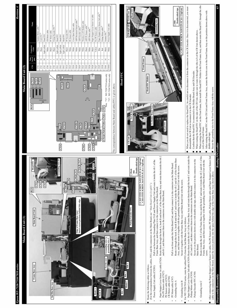
Ep
son
WF
-752
0/7
51
0/7
010
ser
ies
Rev
isio
n A
Dis
ass
embly
/Rea
ssem
bly
Rou
tin
g F
FC
s/ca
ble
s65
Main
Board
Un
it (
1)
Route
the
foll
ow
ing c
able
s as
foll
ow
s.
(Fo
r th
e co
rres
po
nd
ence
bet
wee
n t
he
cab
les,
FF
Cs
and
th
e co
nn
ecto
rs o
n t
he
Mai
n B
oar
d, se
e “
Mai
n B
oar
d U
nit
(2)
(p65)”
.)
•P
ow
er S
up
ply
Un
it c
able
(C
N5
01
)P
ull
it
out
bet
wee
n t
he
Gro
un
din
g P
late
FA
X a
nd P
ow
er S
up
ply
Un
it a
nd
ro
ute
it
insi
de
the
rib
1 o
f th
e
Fra
me
Bas
e A
ssy
, an
d t
hen
co
nn
ect
it t
o t
he
con
nec
tor
on
th
e M
ain
Bo
ard
.
•P
aper
Sto
pp
er L
ever
Sen
sor
1st
cab
le (
CN
26
)R
ou
te t
hem
thro
ug
h t
he
ho
ok
A, h
oo
k B
and
ho
ok
C o
f th
e F
ram
e B
ase
Ass
y a
nd r
oute
th
em i
nsi
de
the
rib
2
Pre
-PE
Sen
sor
cab
le (
CN
27
)an
d r
ib 1
, an
d t
hen
co
nn
ect
them
to t
he
con
nec
tors
on t
he
Mai
n B
oar
d.
PE
Sen
sor
cable
(C
N15)
CR
Mo
tor
cab
le (
CN
6)
•P
F M
oto
r ca
ble
(C
N7
)P
ull
it
out
fro
m u
nd
er t
he
Mai
n B
oar
d U
nit
, an
d t
hen
co
nn
ect
it t
o t
he
con
nec
tor
on
th
e M
ain B
oar
d.
•G
rou
nd
ing
wir
e A
Ro
ute
it
thro
ug
h t
he
ho
ok
A, h
oo
k B
an
d h
oo
k C
an
d r
ou
te i
t in
sid
e th
e ri
b 2
an
d r
ib 1
of
the
Fra
me
Bas
e
Ass
y, an
d t
hen
sec
ure
it
tog
eth
er w
ith
th
e g
rou
nd
ing
wir
e B
an
d M
ain
Boar
d U
nit
wit
h t
he
scre
w.
•G
rou
nd
ing
wir
e B
Sec
ure
it
tog
eth
er w
ith t
he
Fra
me
Bas
e A
ssy
an
d M
ain
Boar
d U
nit
wit
h t
he
scre
w.
For
WF
-7520/7
010 s
erie
s, r
oute
th
e ca
ble
s/F
FC
s fr
om
th
e 2
nd
Bin
Bas
e A
ssy a
s fo
llo
ws.
•P
aper
Sto
pper
Lev
er S
enso
r 2nd c
able
(C
N29)
Ro
ute
th
em i
nsi
de
the
rib
3 o
f th
e F
ram
e B
ase
Ass
y a
nd
rou
te t
hem
th
rou
gh
th
e h
oo
k C
an
d r
ou
te i
nsi
de
the
Pic
kup
Mo
tor
cab
le (
CN
30
)ri
b 2
an
d r
ib 1
, an
d t
hen
co
nn
ect
them
to t
he
connec
tors
on t
he
Mai
n B
oar
d.
•P
ick
up
En
cod
er F
FC
(C
N8
)S
ecu
re i
t o
n t
he
po
siti
on
sh
ow
n a
bo
ve
wit
h d
oub
le-s
ide
tap
e, a
nd t
hen
co
nnec
t it
to
th
e co
nn
ecto
r o
n t
he
Mai
n B
oar
d.
•G
rou
nd
ing
wir
e C
Ro
ute
it
insi
de
the
rib
3 o
f th
e F
ram
e B
ase
Ass
y a
nd
th
e h
oo
k C
and
route
it
insi
de
the
rib 2
and r
ib 1
of
the
Fra
me
Bas
e A
ssy
, an
d t
hen
sec
ure
it
tog
eth
er w
ith
th
e g
rou
nd
ing
wir
e A
an
d M
ain
Bo
ard
Un
it w
ith t
he
scre
w.
Aft
er c
on
nec
tin
g t
he
Pap
er S
top
per
Lev
er S
enso
r 1
st c
able
, P
re-P
E S
enso
r ca
ble
, P
F M
oto
r ca
ble
, P
ick
up
Mo
tor
cab
le a
nd
Pap
er S
top
per
Lev
er S
enso
r 2
nd
cab
le t
o t
he
con
nec
tors
on t
he
Mai
n B
oar
d, in
sert
th
e ex
cess
po
rtio
ns
into
the
spac
e beh
ind t
he
edge
of
the
Fra
me
Bas
e A
ssy s
ho
wn a
bove.
Pic
ku
p E
ncod
er F
FC
Gro
un
din
g w
ire
A,
gro
un
din
g w
ire C
Ferr
ite c
ore
Ho
ok
A
Hoo
k B
Hoo
k C
Rib
3
Rib
2R
ib 1
C.B
.P-T
ITE
SC
RE
W 3
x10
F/Z
N-3
C (
6 ±
1 k
gf·
cm
)
Head
FF
C
Gro
un
din
g w
ire
B
CN
11
CN
12
CN
13
Ba
ckM
ain
Bo
ard
Un
itF
ram
e B
ase
Ass
y
CN
50
1
CN
6
CN
15
CN
8
CN
27
CN
29
CN
26
CN
30C
N7
C.B
.S-T
ITE
SC
RE
W 3
x6 F
/ZN
-3C
(6
± 1
kgf·
cm)
Ed
ge o
f F
ra
me B
ase
Ass
y:
Inse
rt e
xce
ss p
ort
ion
s b
ehin
d t
his
ed
ge.
2n
d B
in B
ase
Ass
y
Hoo
k
Do
ub
le-s
ided
ta
pe
Rib
Main
Board
Un
it (
2)
Th
e co
rres
po
nd
ence
bet
wee
n M
ain
Boar
d a
nd
cab
les/
FF
Cs
is g
iven
ab
ov
e.
CN
2
CN
3
CN
5
CN
14
CN
24
CN
30
CN
6
CN
7
CN
22
CN
41
CN
50
1
CN
19
CN
15
CN
18
CN
8
CN
29
CN
16
CN
21
CN
26
CN
27
CN
#
Nu
m
ber o
f
pin
s
Co
nn
ecto
r
Co
lor
Na
me
CN
24
Wh
ite
Sca
nn
er M
oto
r ca
ble
*1
CN
31
0B
lack
FA
X F
FC
*1
CN
52
0L
igh
t y
ello
wP
anel
FF
C
CN
62
Wh
ite
CR
Moto
r ca
ble
CN
72
Bla
ckP
F M
oto
r ca
ble
CN
85
Bla
ckP
ick
up
En
cod
er F
FC
*2
CN
11
14
Lig
ht
yel
low
Hea
d F
FC
CN
12
14
Lig
ht
yel
low
Hea
d F
FC
CN
13
21
Lig
ht
yel
low
Hea
d F
FC
CN
14
5B
lack
PF
En
cod
er F
FC
CN
15
3W
hit
eP
E S
enso
r ca
ble
CN
16
2W
hit
eC
ov
er O
pen
Sen
sor
cab
le
CN
18
3W
hit
eA
DF
Do
cum
ent
Sen
sor
cab
le*
1
CN
19
4W
hit
eA
DF
En
cod
er c
able
*1
CN
21
4W
hit
eW
irel
ess
LA
N M
od
ule
cab
le
CN
22
5B
lack
AD
F P
E S
enso
r ca
ble
*1
CN
24
2W
hit
eA
DF
Mo
tor
cab
le*
1
CN
26
3B
lack
Pap
er S
top
per
Lev
er S
enso
r 1
st c
able
CN
27
3Y
ello
wP
re-P
E S
enso
r ca
ble
CN
29
3B
lue
Pap
er S
top
per
Lev
er S
enso
r 2
nd
cab
le*
2
CN
30
2R
edP
ick
up
Mo
tor
cab
le*2
CN
41
16
Bla
ckS
can
ner
FF
C*1
CN
501
5W
hit
eP
ow
er S
up
ply
Un
it c
able
CN
11
CN
12
CN
13
Back
Note
"*1":
WF
-75
20/7
510
ser
ies
only
"*2":
WF
-75
20/7
010
ser
ies
only
Hea
d F
FC
Wh
en y
ou
do
no
t n
eed
to
rep
lace
th
e H
ead
FF
C, b
e ca
refu
l n
ot
to d
isco
nn
ect
it f
rom
the
conn
ecto
r on t
he
CR
Enco
der
. O
nce
it
is d
isco
nnec
ted,
you m
ust
dis
asse
mb
le t
he
CR
Un
it t
o r
eco
nnec
t it
to
th
e C
R E
nco
der
.
Confi
rm t
hat
the
Hea
d F
FC
is
connec
ted t
o t
he
Hold
er B
oar
d A
ssy a
nd C
R E
nco
der
.
Wh
en r
ou
tin
g t
he
Hea
d F
FC
on
th
e si
de
of
the
CR
Un
it,
mak
e su
re t
o r
ou
te i
t th
rou
gh
th
e ri
bs
(x3)
of
the
CR
Unit
show
n a
bove.
Wh
en r
ou
tin
g t
he
Hea
d F
FC
on
th
e F
ron
t F
ram
e, f
irst
in
stal
l th
e H
ead
FF
C H
old
er t
o t
he
Fro
nt
Fra
me
Ass
y,
and
th
en r
ou
te t
he
Hea
d F
FC
th
rou
gh
th
e ri
bs
(x4)
of
the
Fro
nt
Fra
me.
Aft
er r
outi
ng t
he
Hea
d F
FC
on t
he
CR
Unit
an
d F
ron
t F
ram
e A
ssy
, se
cure
th
e fe
rrit
e co
re t
o t
he
Fro
nt
Fra
me
Ass
y o
n t
he
po
siti
on s
ho
wn
ab
ov
e w
ith
do
uble
-sid
ed t
ape.
Sec
ure
the
gro
und
ing w
ire
to t
he
Fro
nt
Fra
me
Ass
y w
ith
th
e sc
rew
.
Fer
rite
core
13
0-d
igit
sid
e
Head
FF
C
Gro
un
din
g w
ire
C.B
.P-T
ITE
SC
RE
W 3
x1
0 F
/ZN
-3C
(6 ±
1 k
gf·
cm)
CR
Un
it
Head
FF
C
To
CR
En
co
der
To
Ho
lder
Bo
ard
Ass
y
Fro
nt
Fra
me
Rib
Dou
ble
-sid
ed t
ap
e
Hea
d F
FC
Hold
er

Ep
son
WF
-752
0/7
51
0/7
010
ser
ies
Rev
isio
n A
Dis
ass
embly
/Rea
ssem
bly
Rou
tin
g F
FC
s/ca
ble
s66
Sca
nn
er M
oto
r A
ssy
When
ro
uti
ng
Sca
nn
er M
oto
r ca
ble
an
d s
can
ner
gro
un
din
g w
ire,
fo
llo
w
the
pro
ced
ure
bel
ow
.
1.
Ro
ute
th
e sc
ann
er g
rou
nd
ing
wir
e th
rou
gh
th
e h
oo
ks
and
rib
s, a
nd
in
sert
it
into
th
e h
ole
of
the
Sca
nner
Housi
ng L
ow
er.
2.
Inst
all
the
Sca
nner
Moto
r A
ssy. (p
62)
3.
Ro
ute
th
e S
cann
er M
oto
r ca
ble
th
rou
gh
th
e h
oo
ks
and
rib
s, a
nd
in
sert
it
in
to t
he
ho
le o
f th
e S
can
ner
Ho
usi
ng
Lo
wer
.
Aft
er i
nse
rtin
g t
he
Sca
nner
Moto
r ca
ble
and s
canner
gro
undin
g w
ire
into
th
e hole
of
the
Sca
nner
Housi
ng L
ow
er, co
nfi
rm t
he
Sca
nner
Moto
r ca
ble
is
ov
er t
he
scan
ner
gro
un
din
g w
ire.
Sca
nn
er
Moto
r
cab
le
Rou
te
insi
de
rib
.
Sca
nn
er
Mo
tor
Ass
y
Aft
er S
can
ner
Moto
r A
ssy i
s in
stall
ed
Ho
le o
f S
can
ner
Hou
sin
g L
ow
er
Ho
ok
Rib
Ho
ok
Rib
Bef
ore
Sca
nn
er M
oto
r A
ssy i
s in
stall
ed
Sca
nn
er g
rou
nd
ing
wir
e
Ho
le o
f S
can
ner
Ho
usi
ng L
ow
er
Rou
te
insi
de
rib
.
Bott
om
of
the
Sca
nn
er U
nit
Wh
en r
ou
tin
g t
he
cab
les/
FF
Cs
on
th
e b
ott
om
of
the
Sca
nner
Unit
, fo
llow
the
pro
cedure
bel
ow
.
1.
Pull
th
e S
can
ner
FF
C o
ut
fro
m t
he
ho
le A
of
the
Sca
nn
er H
ou
sin
g L
ow
er,
and s
ecure
it
on t
he
posi
tion s
how
n a
bove
wit
h d
ouble
-sid
ed t
ape.
2.
Pull
th
e S
can
ner
Mo
tor
cab
le a
nd s
can
ner
gro
un
din
g w
ire
ou
t fr
om
th
e
hole
B o
f th
e S
canner
Housi
ng L
ow
er.
3.
Inse
rt t
he
Sca
nner
FF
C i
nto
th
e h
ole
1 o
f th
e S
canner
FF
C C
over
, an
d
inse
rt t
he
Sca
nn
er M
oto
r ca
ble
an
d s
can
ner
gro
un
din
g w
ire
into
th
e h
ole
2
of
the
Sca
nn
er F
FC
.
4.
Inst
all
the
Sca
nn
er F
FC
Cov
er t
o t
he
Sca
nner
Housi
ng L
ow
er. (p
62
)
Sca
nn
er M
oto
r ca
ble
Ho
le A
Ho
le B
Do
ub
le-
sid
ed t
ap
e
Bef
ore
Sca
nn
er F
FC
Cover
is
inst
all
ed
Sca
nn
er F
FC
Cover
Hole
1H
ole
2
Sca
nn
er g
ro
un
din
g w
ire
Bo
tto
m o
f S
can
ner
Un
it
Sca
nn
er F
FC
Co
ver
Sca
nn
er F
FC
Wh
en r
outi
ng
th
e S
can
ner
FF
C,
foll
ow
th
e p
roce
du
re b
elo
w.
1.
Fo
ld t
he
Sca
nn
er F
FC
alo
ng
th
e fo
ld l
ines
an
d r
ou
te t
he
FF
C t
hro
ug
h t
he
rib A
and
alo
ng
th
e st
and
ard
lin
e so
as
no
t to
let
the
FF
C t
ou
ch t
he
wal
l o
f th
e S
canner
Housi
ng L
ow
er,
and t
hen
inse
rt t
he
FF
C i
nto
the
hole
of
the
Sca
nner
Housi
ng L
ow
er.
2.
Sec
ure
th
e S
can
ner
FF
C o
n t
he
po
siti
on s
how
n a
bove
on t
he
Sca
nn
er H
ou
sin
g L
ow
er w
ith
do
ub
le-s
ided
tap
e (x
4).
3.
Con
nec
t th
e S
can
ner
FF
C t
o t
he
con
nec
tor
on
th
e C
IS M
od
ule
, an
d s
ecure
th
e S
can
ner
FF
C o
n t
he
po
siti
on
sh
ow
n a
bo
ve
on
th
e C
IS M
od
ule
wit
h d
ou
ble
-si
ded
tap
e.
4.
Inst
all
the
CIS
Mo
dule
to
th
e S
can
ner
Car
riag
e.
5.
Rou
te t
he
Sca
nn
er F
FC
un
der
th
e ri
b B
(x
2)
of
the
Sca
nner
Car
riag
e, a
nd c
onfi
rm t
he
FF
C d
oes
not
com
e over
th
e guid
e ri
bs
(x2
) o
f th
e S
can
ner
Car
riag
e.
Ste
p 1
, 2
Ho
le o
f S
can
ner
Ho
usi
ng L
ow
er
Rib
A
Do
ub
le-s
ided
tap
e
Wa
ll o
f S
ca
nn
er
Ho
usi
ng
Low
er
Sca
nn
er
FF
C
Sta
nd
ard
lin
e
Co
nn
ecto
r
CIS
Mo
du
le
Do
ub
le-s
ided
tap
e
Ste
p 3
Sca
nn
er F
FC
Rib
B
Gu
ide
rib
Ste
p 5
Sca
nn
er F
FC
Sca
nn
er H
ou
sin
g L
ow
er
Sca
nn
er C
arr
iag
e

Disassembly/Reassembly 67
Epson WF-7520/7510/7010 series Revision A
4.5 Connector Summary
Cable connections of this printer are shown below.
Figure 4-3. Connector Diagram
B M Y C
2.5 inch LCD Module
CB69 PNL
CB59 PNL
CA70 SUB
PW Sensor
CR Encoder Board
Wireless LAN Module
Cover Open Sensor
CN7
CN24
CN27 CN29 CN30CN26
J1
CN1Printhead
CSIC
CR Contact Module
CN11 CN12 CN13
CN21CN20
CN9/10
CN16
CN5CR Motor
AC in
PF Motor
Pickup Motor
ADF Motor
CIS Module
ADF Encoder
PE Sensor
ADF Document Sensor
Scanner Motor
Paper Stopper Lever Sensor 1st
Paper Stopper Lever Sensor 2nd
Pre-PE Sensor
USB Host (WF-7520/7510 series)
Ethernet
USB
Memory Card (WF-7520/7510 series)
FAX Board
(WF-7520/7510 series)
PF Encoder
ADF PE Sensor
CN1
CN2
CA96 Main
CA69 IF
CB28 PSH
CR Unit
CN2
CN18
CN15
CN19
CN6
CN501
CN41
CN3
CN1
CN14
CN22
CN4
CN1
CN1
CN1
CN2 CN1
CN2
CN8
Pickup Encoder
2nd Bin Base Assy
(WF-7520/7010 series)
ADF Unit
(WF-7520/7510 series)
Scanner Unit
(WF-7520/7510 series)
Panel Unit (WF-7010 series)
Panel Unit
(WF-7520/7510 series)
*
Note "*": Whether or not the Wireless LAN Module is mounted
depends on the destinations. (See Table 1-1.)

CHAPTER 5
ADJUSTMENT

Adjustment Required Adjustments 69
Epson WF-7520/7510/7010 series Revision A
5.1 Required Adjustments
The table from the following page lists the required adjustments depending upon the parts being repaired or
replaced. Find the part(s) you removed or replaced, and check which adjustment(s) must be carried out.
If the EEPROM data cannot be read out from the old Main Board using the Adjustment Program when replacing the Main Board is required, the Waste Ink Tray Assy must be replaced with the Main Board at the same time.
After all required adjustments are complete, use the “Final check pattern print” function
to print all adjustment patterns for final check. If you find a problem with the printout
patterns, carry out the adjustment again.
When replacing the Main Board and the Printer Mechanism (Frame Base Assy) at the same time, the adjustment should be made after performing the initial setting.
In this chapter, the product names are called as follows:
• WF-7520 series: Epson WF-7525/Epson WF-7521/Epson WF-7520
• WF-7510 series: Epson WF-7515/Epson WF-7511/Epson WF-7510
• WF-7010 series: Epson WF-7018/Epson WF-7015/Epson WF-7012/Epson WF-7011/
Epson WF-7010
The table items and marks used in the “Required Adjustment List” provided on the
following pages have the following meanings.
• “O” indicates that the adjustment must be carried out.
• “---” indicates that the adjustment is not required.
• The “Mechanism Adjustment” should be performed just after reinstalling or
reassembling the part or unit. (See “Table 5-1 Required Adjustment List (Mechanism
Adjustment) (p70)”.)
• The “Adjustments using the Adjustment Program” need to be performed after
reassembling the printer completely. (See “Table 5-2 Required Adjustment List
(Adjustment using the Adjustment Program) (p71)”.)
If you have removed or replaced multiple parts, make sure to check the required
adjustments for the all parts. And when multiple adjustments must be carried out, be
sure to carry them out in the order given in the “Priority” row.

Adjustment Required Adjustments 70
Epson WF-7520/7510/7010 series Revision A
Note 1: The mechanism adjustment is not necessary for the parts which are not mentioned above.
2: After the mechanism adjustment is performed, make sure to execute the adjustment using the Adjustment Program.
(See “Table 5-2 Required Adjustment List (Adjustment using the Adjustment Program) (p71)”.)
Table 5-1. Required Adjustment List (Mechanism Adjustment)
Adjustment Type Mechanism adjustment
Priority 1 2 3
Adjustment ItemPF Timing Belt tension
checkChecking the platen gap
Scanner Timing Belt
tension check
Purpose
Check if the tension of the
PF Timing Belt is within
the standard.
Check if the PG is within
the standard.
Check if the tension of the
Scanner Timing Belt is
within the standard.
Par
t N
ame
CR Guide PlateRemove --- --- ---
Replace --- O ---
PrintheadRemove --- --- ---
Replace --- O ---
Frame Base AssyRemove --- --- ---
Replace O O ---
2nd Bin Base AssyRemove --- --- ---
Replace O O ---
PF MotorRemove O --- ---
Replace O --- ---
Paper Guide Front AssyRemove O --- ---
Replace O O ---
EJ RollerRemove O --- ---
Replace O --- ---
PF Timing BeltRemove O --- ---
Replace O --- ---
EJ PulleyRemove --- --- ---
Replace O --- ---
Scanner CarriageRemove --- --- O
Replace --- --- O
Scanner Motor AssyRemove --- --- O
Replace --- --- O
How to judge
See “5.2.1 PF Timing Belt
Tension Check (p75)” for
the details.
See “5.2.2 Checking the
Platen Gap (p76)” for the
details.
See “5.2.3 Scanner Timing
Belt Tension Check (p77)”
for the details.
Adjustment program --- --- ---
Tool (p 75) (p 76) (p 77)

Ep
son
WF
-752
0/7
51
0/7
010
ser
ies
Rev
isio
n A
Adju
stm
ent
Requ
ired
Adju
stm
ents
71
Tab
le 5
-2.
Req
uir
ed A
dju
stm
ent
Lis
t (A
dju
stm
en
t u
sin
g t
he
Ad
just
men
t P
rogra
m)
Ad
just
men
t T
yp
eA
dju
stm
ent
usi
ng
th
e A
dju
stm
ent
Pro
gra
m
Pri
ori
ty1
24
56
37
89
10
11
12
13
14
15
16
17
18
19
Ad
just
men
t It
emE
EP
RO
M
da
ta c
op
y
Init
iali
ze
Set
tin
g
(in
clu
din
g
MA
C a
dd
ress
sett
ing)
Ink
ch
arg
eH
ea
d I
D
inp
ut
Main
ten
an
ce
cou
nte
r
PE
Det
ecto
r
con
firm
ati
on
PF
/ E
J
ad
just
men
t
Fir
st d
ot
posi
tion
/ P
W
ad
just
men
tB
i-D
ad
just
men
t
Hea
d
an
gu
lar
ad
just
men
t
PF
ba
nd
ad
just
men
t
PE
ad
just
men
t
Pap
er
skew
ad
just
men
t
PF
/ E
J
det
erio
rati
on
off
set
PW
det
erio
rati
on
off
set
CR
moto
r
hea
t
pro
tect
ion
con
tro
l
PF
mo
tor
hea
t
pro
tect
ion
con
tro
l
AS
F m
oto
r
hea
t
pro
tecti
on
con
tro
l*1
Sca
nn
er
mo
tor
heat
pro
tect
ion
con
trol*
21
st c
ass
ett
e2n
d c
ass
ette
*1
1st
ca
ssett
e2n
d c
ass
ette
*1
Pu
rpo
se
To c
opy
adju
stm
ent
val
ues
or
the
like
sto
red o
n
the
old
Mai
n
Boar
d t
o t
he
new
boar
d
when
th
e M
ain
Boar
d n
eeds
to
be
repla
ced.
To w
rite
sal
e-
des
tin
atio
n-
spec
ific
sett
ing
s an
d
the
seri
al
nu
mb
er i
nto
the
Mai
n
Bo
ard
aft
er
repla
cin
g i
t.
To f
ill
ink
thro
ug
ho
ut
the
ink
pat
h to
mak
e al
l th
e
no
zzle
s re
ady
for
pri
nti
ng
.
To
corr
ect
char
acte
rist
ic
var
iati
on
of
the
rep
lace
d
Pri
nth
ead
by
ente
rin
g i
ts
Pri
nth
ead
ID
(Hea
d I
D).
To r
eset
th
e
was
te i
nk
cou
nte
r af
ter
repla
cing t
he
Was
te I
nk
Pad
.
Confi
rm t
he
PE
sen
sor'
s
chat
teri
ng a
fter
det
ecti
ng t
he
end o
f th
e
pap
er f
alls
wit
hin
th
e
spec
ifie
d
per
iod
.
To
corr
ect
var
iati
on
s in
pap
er f
eed
accu
racy
to
ach
iev
e
hig
her
pri
nt
qual
ity.
To c
orr
ect
the
pri
nt
star
t
po
siti
on
in
th
e ca
rria
ge
mo
vin
g d
irec
tio
n t
hro
ug
h
soft
war
e co
ntr
ol.
To
corr
ect
pri
nt
star
t
tim
ing
in
bid
irec
tio
nal
pri
nti
ng
thro
ug
h
soft
war
e
con
tro
l.
To c
orr
ect
tilt
of
the
Pri
nth
ead
cause
d a
t th
e
inst
alla
tio
n
thro
ugh
soft
war
e
con
tro
l.
To c
orr
ect
var
iati
ons
in
pap
er f
eed
accu
racy
to
achie
ve
hig
her
pri
nt
qual
ity i
n
ban
d p
rin
ting.
To c
orr
ect
the
pap
er d
etec
tion
posi
tio
ns
and t
he
mo
unti
ng
posi
tio
ns
of
the
PE
Sen
sor
by
soft
war
e co
ntr
ol.
To
alig
n pr
int
star
t pos
itio
n at
0-
digi
t sid
e w
ith
that
at 8
0-di
git
side
in b
i-di
rect
iona
l ban
d pr
inti
ng, t
imin
g of
fir
ing
ink
drop
let i
s ad
just
ed th
roug
h so
ftw
are
cont
rol.
To r
eset
th
e
cou
nte
r o
r se
t
it t
o i
ts
max
imu
m
acco
rdin
g t
o
the
rep
lace
d
par
ts.
To
res
et t
he
cou
nte
r
acco
rdin
g t
o
the
rep
lace
d
par
ts.
To
mea
sure
and
corr
ect th
e
elec
tric
al
var
iati
on
of
the
CR
Moto
r
and
th
e P
ow
er
Su
pp
ly B
oar
d.
To
mea
sure
and
co
rrec
t th
e
elec
tric
al
var
iati
on
of
the
PF
Mo
tor
and
th
e P
ow
er
Su
pp
ly B
oar
d.
To
mea
sure
and
co
rrec
t th
e
elec
tric
al
var
iati
on
of
the
Pic
ku
p
Mo
tor
and
th
e
Po
wer
Su
pp
ly
Bo
ard
.
To
mea
sure
and
co
rrec
t th
e
elec
tric
al
var
iati
on
of
the
Sca
nn
er
Mo
tor
and
th
e
Po
wer
Su
pp
ly
Bo
ard
.
Part Name
Mai
n B
oar
d
Unit
Rem
ove
---
---
---
---
---
---
---
---
---
---
---
---
---
---
---
---
---
---
---
---
---
Rep
lace
(Rea
d O
K)
O--
---
---
---
---
---
---
---
---
---
---
---
---
---
---
---
---
---
---
---
-
Rep
lace
(Rea
d N
G)
---
O--
-O
O*3
---
OO
OO
OO
OO
OO
OO
OO
---
Pow
er
Sup
ply
Unit
Rem
ove
---
---
---
---
---
---
---
---
---
---
---
---
---
---
---
---
---
---
---
---
---
Rep
lace
---
---
---
---
---
---
---
---
---
---
---
---
---
---
---
---
---
OO
O--
-
CR
Unit
Rem
ove
---
---
---
---
---
---
---
OO
---
---
---
OO
---
---
---
---
---
---
---
Rep
lace
---
---
---
---
---
---
---
OO
OO
---
OO
O--
-O
---
---
---
---
CR
Guid
e P
late
Rem
ove
---
---
---
---
---
---
---
OO
---
---
---
OO
---
---
---
---
---
---
---
Rep
lace
---
---
---
---
---
---
---
OO
OO
---
OO
O--
---
---
---
---
---
-
Pap
er G
uid
e
Lo
wer
Poro
us
Pad
Rem
ove
---
---
---
---
---
---
---
---
---
---
---
---
---
---
---
---
---
---
---
---
---
Rep
lace
---
---
---
---
O--
---
---
---
---
---
---
---
---
---
---
---
---
---
---
---
-
Pri
nto
ut
pat
tern
---
---
---
---
---
---
---
---
---
---
---
---
---
---
Ho
w t
o j
ud
ge
---
See
“ 5
.2.4
MA
C A
dd
ress
Set
tin
g (p
78
)”
for
the
det
ails
of
the
MA
C
add
ress
sett
ing
.
---
---
---
---
Ex
amin
e th
e
pri
nto
ut
pat
tern
s an
d
ente
r th
e
val
ue
for
the
pat
tern
wit
h
no o
ver
lap
and g
ap
bet
wee
n t
he
two
rect
ang
les.
PW
A
dju
stm
ent
Exa
min
e th
e m
isal
igne
d li
nes
prin
ted
on t
op,
bott
om, l
eft,
and
ri
ght
of t
he
pape
r, a
nd e
nter
th
e nu
mbe
r be
side
the
lin
e th
at i
s ex
actl
y 5
mm
aw
ay f
rom
th
e pa
per
edge
fo
r ea
ch s
ide.
1st
dot
ad
just
men
t
Exa
min
e th
e li
nes
on t
he l
eft
side
of
pape
r,
and
ente
r th
e nu
mbe
r be
side
th
e li
ne t
hat
over
laps
wit
h th
e ho
rizo
ntal
li
ne.
1st
dot
ad
just
men
t
Ex
amin
e th
e m
isal
ign
ed
lines
pri
nte
d
on
lef
t, a
nd
en
ter
the
nu
mber
b
esid
e th
e li
ne
that
is
exac
tly
5 m
m a
way
fr
om
th
e pap
er e
dge.
Ex
amin
e th
e
pri
nto
ut
pat
tern
s fo
r
each
of
the
fou
r m
odes
,
and e
nte
r th
e
val
ue
for
the
pat
tern
wit
h
no g
ap a
nd
over
lap
fo
r
each
mo
de.
Ban
d
patt
ern
Ente
r th
e v
alu
es o
f th
e m
ost
str
aig
ht
lin
es.
Mic
row
eave
patt
ern
Ente
r th
e v
alu
e fo
r th
e g
rou
p o
f w
hic
h t
he
gap
s b
etw
een
th
e tw
o c
olo
r b
ars
are
the
smal
lest
.
Ex
amin
e th
e
mis
alig
ned
lines
pri
nte
d
on
to
p a
nd
bo
tto
m o
f th
e
pap
er, an
d
ente
r th
e
nu
mber
bes
ide
the
lin
e
that
is
exac
tly
5 m
m a
way
from
th
e
pap
er e
dg
e fo
r
each
sid
e.
---
---
Ex
amin
e th
e
pri
nto
ut
pat
tern
an
d
ente
r th
e
nu
mber
of
the
one
wit
h t
he
leas
t g
ap a
nd
ov
erla
p
bet
wee
n t
he
two
dif
fere
nt
colo
red
lin
es.
---
---
---
---
---
---
Adju
stm
ent
pro
gra
mO
OO
OO
OO
OO
OO
OO
OO
OO
OO
OO
To
ol
---
---
---
---
---
---
---
Rule
rR
ule
r--
---
---
---
---
---
---
---
---
---
---
---
-
No
te"*
1":
WF
-752
0/7
010
ser
ies
only
"*2
":W
F-7
52
0/7
510
ser
ies
only
"*3
":R
epla
cem
ent
of
the
Was
te I
nk
Tra
y A
ssy
/Pap
er G
uid
e L
ow
er P
oro
us
Pad
is
nec
essa
ry
OK
NG
NG
OK
NG
NG
-2
-1 0 1 2
-2-1
01
2
-2-1
01
2
-2
-1 0 1 2
-2
-1 0 1 2
-2
-1 0 1 2
OK
NG
NG
NG
OK
NG
OK
OK
NG
NG
OK
NG
NG

Ep
son
WF
-752
0/7
51
0/7
010
ser
ies
Rev
isio
n A
Adju
stm
ent
Requ
ired
Adju
stm
ents
72
Part Name
Pri
nth
ead
Rem
ove
---
---
---
---
---
---
---
---
---
OO
---
---
---
O--
---
---
---
---
---
-
Rep
lace
---
---
OO
---
---
OO
OO
OO
OO
O--
---
---
---
---
---
-
Was
te I
nk
Tra
y A
ssy
Rem
ove
---
---
---
---
---
---
---
---
---
---
---
---
---
---
---
---
---
---
---
---
---
Rep
lace
---
---
---
---
O--
---
---
---
---
---
---
---
---
---
---
---
---
---
---
---
-
Dup
lex
Un
itR
emo
ve
---
---
---
---
---
---
---
---
---
---
---
---
---
---
---
---
---
---
---
---
---
Rep
lace
---
---
---
---
---
---
OO
O--
---
-O
OO
---
---
---
---
---
---
---
Cas
sett
e A
ssy
1st
Rem
ove
---
---
---
---
---
---
---
---
---
---
---
---
---
---
---
---
---
---
---
---
---
Rep
lace
---
---
---
---
---
---
---
O--
---
---
---
-O
---
---
---
---
---
---
---
---
Fra
me
Bas
e A
ssy
Rem
ove
---
---
---
---
---
O--
---
---
---
---
---
---
---
---
---
---
---
---
---
---
-
Rep
lace
---
---
---
---
---
OO
O--
-O
OO
OO
O--
---
---
---
---
---
-
2n
d B
in B
ase
Ass
y
Rem
ove
---
---
---
---
---
---
---
---
---
---
---
---
---
---
---
---
---
---
---
---
---
Rep
lace
---
---
---
---
---
---
O--
-O
---
---
O--
-O
---
---
---
---
---
O--
-
Cas
sett
e A
ssy
2n
d
Rem
ove
---
---
---
---
---
---
---
---
---
---
---
---
---
---
---
---
---
---
---
---
---
Rep
lace
---
---
---
---
---
---
---
---
O--
---
---
---
-O
---
---
---
---
---
---
---
Tab
le 5
-2.
Req
uir
ed A
dju
stm
ent
Lis
t (A
dju
stm
en
t u
sin
g t
he
Ad
just
men
t P
rogra
m)
Ad
just
men
t T
yp
eA
dju
stm
ent
usi
ng
th
e A
dju
stm
ent
Pro
gra
m
Pri
ori
ty1
24
56
37
89
10
11
12
13
14
15
16
17
18
19
Ad
just
men
t It
emE
EP
RO
M
da
ta c
op
y
Init
iali
ze
Set
tin
g
(in
clu
din
g
MA
C a
dd
ress
sett
ing)
Ink
ch
arg
eH
ea
d I
D
inp
ut
Main
ten
an
ce
cou
nte
r
PE
Det
ecto
r
con
firm
ati
on
PF
/ E
J
ad
just
men
t
Fir
st d
ot
posi
tion
/ P
W
ad
just
men
tB
i-D
ad
just
men
t
Hea
d
an
gu
lar
ad
just
men
t
PF
ba
nd
ad
just
men
t
PE
ad
just
men
t
Pap
er
skew
ad
just
men
t
PF
/ E
J
det
erio
rati
on
off
set
PW
det
erio
rati
on
off
set
CR
moto
r
hea
t
pro
tect
ion
con
tro
l
PF
mo
tor
hea
t
pro
tect
ion
con
tro
l
AS
F m
oto
r
hea
t
pro
tecti
on
con
tro
l*1
Sca
nn
er
mo
tor
heat
pro
tect
ion
con
trol*
21
st c
ass
ett
e2n
d c
ass
ette
*1
1st
ca
ssett
e2n
d c
ass
ette
*1
Pu
rpo
se
To c
opy
adju
stm
ent
val
ues
or
the
like
sto
red o
n
the
old
Mai
n
Boar
d t
o t
he
new
boar
d
when
th
e M
ain
Boar
d n
eeds
to
be
repla
ced.
To w
rite
sal
e-
des
tin
atio
n-
spec
ific
sett
ing
s an
d
the
seri
al
nu
mb
er i
nto
the
Mai
n
Bo
ard
aft
er
repla
cin
g i
t.
To f
ill
ink
thro
ug
ho
ut
the
ink
pat
h to
mak
e al
l th
e
no
zzle
s re
ady
for
pri
nti
ng
.
To
corr
ect
char
acte
rist
ic
var
iati
on
of
the
rep
lace
d
Pri
nth
ead
by
ente
rin
g i
ts
Pri
nth
ead
ID
(Hea
d I
D).
To r
eset
th
e
was
te i
nk
cou
nte
r af
ter
repla
cing t
he
Was
te I
nk
Pad
.
Confi
rm t
he
PE
sen
sor'
s
chat
teri
ng a
fter
det
ecti
ng t
he
end o
f th
e
pap
er f
alls
wit
hin
th
e
spec
ifie
d
per
iod
.
To
corr
ect
var
iati
on
s in
pap
er f
eed
accu
racy
to
ach
iev
e
hig
her
pri
nt
qual
ity.
To c
orr
ect
the
pri
nt
star
t
po
siti
on
in
th
e ca
rria
ge
mo
vin
g d
irec
tio
n t
hro
ug
h
soft
war
e co
ntr
ol.
To
corr
ect
pri
nt
star
t
tim
ing
in
bid
irec
tio
nal
pri
nti
ng
thro
ug
h
soft
war
e
con
tro
l.
To c
orr
ect
tilt
of
the
Pri
nth
ead
cause
d a
t th
e
inst
alla
tio
n
thro
ugh
soft
war
e
con
tro
l.
To c
orr
ect
var
iati
ons
in
pap
er f
eed
accu
racy
to
achie
ve
hig
her
pri
nt
qual
ity i
n
ban
d p
rin
ting.
To c
orr
ect
the
pap
er d
etec
tion
posi
tio
ns
and t
he
mo
unti
ng
posi
tio
ns
of
the
PE
Sen
sor
by
soft
war
e co
ntr
ol.
To
alig
n pr
int
star
t pos
itio
n at
0-
digi
t sid
e w
ith
that
at 8
0-di
git
side
in b
i-di
rect
iona
l ban
d pr
inti
ng, t
imin
g of
fir
ing
ink
drop
let i
s ad
just
ed th
roug
h so
ftw
are
cont
rol.
To r
eset
th
e
cou
nte
r o
r se
t
it t
o i
ts
max
imu
m
acco
rdin
g t
o
the
rep
lace
d
par
ts.
To
res
et t
he
cou
nte
r
acco
rdin
g t
o
the
rep
lace
d
par
ts.
To
mea
sure
and
corr
ect th
e
elec
tric
al
var
iati
on
of
the
CR
Moto
r
and
th
e P
ow
er
Su
pp
ly B
oar
d.
To
mea
sure
and
co
rrec
t th
e
elec
tric
al
var
iati
on
of
the
PF
Mo
tor
and
th
e P
ow
er
Su
pp
ly B
oar
d.
To
mea
sure
and
co
rrec
t th
e
elec
tric
al
var
iati
on
of
the
Pic
ku
p
Mo
tor
and
th
e
Po
wer
Su
pp
ly
Bo
ard
.
To
mea
sure
and
co
rrec
t th
e
elec
tric
al
var
iati
on
of
the
Sca
nn
er
Mo
tor
and
th
e
Po
wer
Su
pp
ly
Bo
ard
.
Pri
nto
ut
pat
tern
---
---
---
---
---
---
---
---
---
---
---
---
---
---
Ho
w t
o j
ud
ge
---
See
“ 5
.2.4
MA
C A
dd
ress
Set
tin
g (p
78
)”
for
the
det
ails
of
the
MA
C
add
ress
sett
ing
.
---
---
---
---
Ex
amin
e th
e
pri
nto
ut
pat
tern
s an
d
ente
r th
e
val
ue
for
the
pat
tern
wit
h
no o
ver
lap
and g
ap
bet
wee
n t
he
two
rect
ang
les.
PW
A
dju
stm
ent
Exa
min
e th
e m
isal
igne
d li
nes
prin
ted
on t
op,
bott
om, l
eft,
and
ri
ght
of t
he
pape
r, a
nd e
nter
th
e nu
mbe
r be
side
the
lin
e th
at i
s ex
actl
y 5
mm
aw
ay f
rom
th
e pa
per
edge
fo
r ea
ch s
ide.
1st
dot
ad
just
men
t
Exa
min
e th
e li
nes
on t
he l
eft
side
of
pape
r,
and
ente
r th
e nu
mbe
r be
side
th
e li
ne t
hat
over
laps
wit
h th
e ho
rizo
ntal
li
ne.
1st
dot
ad
just
men
t
Ex
amin
e th
e m
isal
ign
ed
lines
pri
nte
d
on
lef
t, a
nd
en
ter
the
nu
mber
b
esid
e th
e li
ne
that
is
exac
tly
5 m
m a
way
fr
om
th
e pap
er e
dge.
Ex
amin
e th
e
pri
nto
ut
pat
tern
s fo
r
each
of
the
fou
r m
odes
,
and e
nte
r th
e
val
ue
for
the
pat
tern
wit
h
no g
ap a
nd
over
lap
fo
r
each
mo
de.
Ban
d
patt
ern
Ente
r th
e v
alu
es o
f th
e m
ost
str
aig
ht
lin
es.
Mic
row
eave
patt
ern
Ente
r th
e v
alu
e fo
r th
e g
rou
p o
f w
hic
h t
he
gap
s b
etw
een
th
e tw
o c
olo
r b
ars
are
the
smal
lest
.
Ex
amin
e th
e
mis
alig
ned
lines
pri
nte
d
on
to
p a
nd
bo
tto
m o
f th
e
pap
er, an
d
ente
r th
e
nu
mber
bes
ide
the
lin
e
that
is
exac
tly
5 m
m a
way
from
th
e
pap
er e
dg
e fo
r
each
sid
e.
---
---
Ex
amin
e th
e
pri
nto
ut
pat
tern
an
d
ente
r th
e
nu
mber
of
the
one
wit
h t
he
leas
t g
ap a
nd
ov
erla
p
bet
wee
n t
he
two
dif
fere
nt
colo
red
lin
es.
---
---
---
---
---
---
Adju
stm
ent
pro
gra
mO
OO
OO
OO
OO
OO
OO
OO
OO
OO
OO
To
ol
---
---
---
---
---
---
---
Rule
rR
ule
r--
---
---
---
---
---
---
---
---
---
---
---
-
No
te"*
1":
WF
-752
0/7
010
ser
ies
only
"*2
":W
F-7
52
0/7
510
ser
ies
only
"*3
":R
epla
cem
ent
of
the
Was
te I
nk
Tra
y A
ssy
/Pap
er G
uid
e L
ow
er P
oro
us
Pad
is
nec
essa
ry
OK
NG
NG
OK
NG
NG
-2
-1 0 1 2
-2-1
01
2
-2-1
01
2
-2
-1 0 1 2
-2
-1 0 1 2
-2
-1 0 1 2
OK
NG
NG
NG
OK
NG
OK
OK
NG
NG
OK
NG
NG

Ep
son
WF
-752
0/7
51
0/7
010
ser
ies
Rev
isio
n A
Adju
stm
ent
Requ
ired
Adju
stm
ents
73
Part Name
Mai
n F
ram
e A
ssy
Rem
ove
---
---
---
---
---
O--
---
---
---
---
---
-O
O--
---
---
---
---
---
---
-
Rep
lace
---
---
---
---
---
OO
---
---
O--
-O
OO
O--
---
-O
---
---
---
Pap
er G
uid
e U
pp
er A
ssy
Rem
ove
---
---
---
---
---
---
---
---
---
---
---
---
---
---
---
---
---
---
---
---
---
Rep
lace
---
---
---
---
---
---
O--
---
-O
OO
---
---
O--
---
---
---
---
---
-
PE
Sen
sor
Lev
er
Rem
ove
---
---
---
---
---
O--
---
---
---
---
---
---
---
---
---
---
---
---
---
---
-
Rep
lace
---
---
---
---
---
OO
---
---
---
---
OO
O--
---
---
---
---
---
---
-
PE
Sen
sor
Rem
ove
---
---
---
---
---
O--
---
---
---
---
---
---
---
---
---
---
---
---
---
---
-
Rep
lace
---
---
---
---
---
O--
---
---
---
---
---
-O
O--
---
---
---
---
---
---
-
CR
Mo
tor
Rem
ove
---
---
---
---
---
---
---
---
---
---
---
---
---
---
---
---
---
---
---
---
---
Rep
lace
---
---
---
---
---
---
---
---
---
---
---
---
---
---
---
---
---
O--
---
---
-
PF
Mo
tor
Rem
ove
---
---
---
---
---
---
---
---
---
---
---
---
---
---
---
---
---
---
---
---
---
Rep
lace
---
---
---
---
---
---
---
---
---
---
---
---
---
---
---
---
---
---
O--
---
-
Fro
nt
Fra
me
Ass
y
Rem
ove
---
---
---
---
---
---
---
---
---
---
---
---
---
---
---
---
---
---
---
---
---
Rep
lace
---
---
---
---
---
---
---
OO
OO
---
OO
O--
---
---
---
---
---
-
Tab
le 5
-2.
Req
uir
ed A
dju
stm
ent
Lis
t (A
dju
stm
en
t u
sin
g t
he
Ad
just
men
t P
rogra
m)
Ad
just
men
t T
yp
eA
dju
stm
ent
usi
ng
th
e A
dju
stm
ent
Pro
gra
m
Pri
ori
ty1
24
56
37
89
10
11
12
13
14
15
16
17
18
19
Ad
just
men
t It
emE
EP
RO
M
da
ta c
op
y
Init
iali
ze
Set
tin
g
(in
clu
din
g
MA
C a
dd
ress
sett
ing)
Ink
ch
arg
eH
ea
d I
D
inp
ut
Main
ten
an
ce
cou
nte
r
PE
Det
ecto
r
con
firm
ati
on
PF
/ E
J
ad
just
men
t
Fir
st d
ot
posi
tion
/ P
W
ad
just
men
tB
i-D
ad
just
men
t
Hea
d
an
gu
lar
ad
just
men
t
PF
ba
nd
ad
just
men
t
PE
ad
just
men
t
Pap
er
skew
ad
just
men
t
PF
/ E
J
det
erio
rati
on
off
set
PW
det
erio
rati
on
off
set
CR
moto
r
hea
t
pro
tect
ion
con
tro
l
PF
mo
tor
hea
t
pro
tect
ion
con
tro
l
AS
F m
oto
r
hea
t
pro
tecti
on
con
tro
l*1
Sca
nn
er
mo
tor
heat
pro
tect
ion
con
trol*
21
st c
ass
ett
e2n
d c
ass
ette
*1
1st
ca
ssett
e2n
d c
ass
ette
*1
Pu
rpo
se
To c
opy
adju
stm
ent
val
ues
or
the
like
sto
red o
n
the
old
Mai
n
Boar
d t
o t
he
new
boar
d
when
th
e M
ain
Boar
d n
eeds
to
be
repla
ced.
To w
rite
sal
e-
des
tin
atio
n-
spec
ific
sett
ing
s an
d
the
seri
al
nu
mb
er i
nto
the
Mai
n
Bo
ard
aft
er
repla
cin
g i
t.
To f
ill
ink
thro
ug
ho
ut
the
ink
pat
h to
mak
e al
l th
e
no
zzle
s re
ady
for
pri
nti
ng
.
To
corr
ect
char
acte
rist
ic
var
iati
on
of
the
rep
lace
d
Pri
nth
ead
by
ente
rin
g i
ts
Pri
nth
ead
ID
(Hea
d I
D).
To r
eset
th
e
was
te i
nk
cou
nte
r af
ter
repla
cing t
he
Was
te I
nk
Pad
.
Confi
rm t
he
PE
sen
sor'
s
chat
teri
ng a
fter
det
ecti
ng t
he
end o
f th
e
pap
er f
alls
wit
hin
th
e
spec
ifie
d
per
iod
.
To
corr
ect
var
iati
on
s in
pap
er f
eed
accu
racy
to
ach
iev
e
hig
her
pri
nt
qual
ity.
To c
orr
ect
the
pri
nt
star
t
po
siti
on
in
th
e ca
rria
ge
mo
vin
g d
irec
tio
n t
hro
ug
h
soft
war
e co
ntr
ol.
To
corr
ect
pri
nt
star
t
tim
ing
in
bid
irec
tio
nal
pri
nti
ng
thro
ug
h
soft
war
e
con
tro
l.
To c
orr
ect
tilt
of
the
Pri
nth
ead
cause
d a
t th
e
inst
alla
tio
n
thro
ugh
soft
war
e
con
tro
l.
To c
orr
ect
var
iati
ons
in
pap
er f
eed
accu
racy
to
achie
ve
hig
her
pri
nt
qual
ity i
n
ban
d p
rin
ting.
To c
orr
ect
the
pap
er d
etec
tion
posi
tio
ns
and t
he
mo
unti
ng
posi
tio
ns
of
the
PE
Sen
sor
by
soft
war
e co
ntr
ol.
To
alig
n pr
int
star
t pos
itio
n at
0-
digi
t sid
e w
ith
that
at 8
0-di
git
side
in b
i-di
rect
iona
l ban
d pr
inti
ng, t
imin
g of
fir
ing
ink
drop
let i
s ad
just
ed th
roug
h so
ftw
are
cont
rol.
To r
eset
th
e
cou
nte
r o
r se
t
it t
o i
ts
max
imu
m
acco
rdin
g t
o
the
rep
lace
d
par
ts.
To
res
et t
he
cou
nte
r
acco
rdin
g t
o
the
rep
lace
d
par
ts.
To
mea
sure
and
corr
ect th
e
elec
tric
al
var
iati
on
of
the
CR
Moto
r
and
th
e P
ow
er
Su
pp
ly B
oar
d.
To
mea
sure
and
co
rrec
t th
e
elec
tric
al
var
iati
on
of
the
PF
Mo
tor
and
th
e P
ow
er
Su
pp
ly B
oar
d.
To
mea
sure
and
co
rrec
t th
e
elec
tric
al
var
iati
on
of
the
Pic
ku
p
Mo
tor
and
th
e
Po
wer
Su
pp
ly
Bo
ard
.
To
mea
sure
and
co
rrec
t th
e
elec
tric
al
var
iati
on
of
the
Sca
nn
er
Mo
tor
and
th
e
Po
wer
Su
pp
ly
Bo
ard
.
Pri
nto
ut
pat
tern
---
---
---
---
---
---
---
---
---
---
---
---
---
---
Ho
w t
o j
ud
ge
---
See
“ 5
.2.4
MA
C A
dd
ress
Set
tin
g (p
78
)”
for
the
det
ails
of
the
MA
C
add
ress
sett
ing
.
---
---
---
---
Ex
amin
e th
e
pri
nto
ut
pat
tern
s an
d
ente
r th
e
val
ue
for
the
pat
tern
wit
h
no o
ver
lap
and g
ap
bet
wee
n t
he
two
rect
ang
les.
PW
A
dju
stm
ent
Exa
min
e th
e m
isal
igne
d li
nes
prin
ted
on t
op,
bott
om, l
eft,
and
ri
ght
of t
he
pape
r, a
nd e
nter
th
e nu
mbe
r be
side
the
lin
e th
at i
s ex
actl
y 5
mm
aw
ay f
rom
th
e pa
per
edge
fo
r ea
ch s
ide.
1st
dot
ad
just
men
t
Exa
min
e th
e li
nes
on t
he l
eft
side
of
pape
r,
and
ente
r th
e nu
mbe
r be
side
th
e li
ne t
hat
over
laps
wit
h th
e ho
rizo
ntal
li
ne.
1st
dot
ad
just
men
t
Ex
amin
e th
e m
isal
ign
ed
lines
pri
nte
d
on
lef
t, a
nd
en
ter
the
nu
mber
b
esid
e th
e li
ne
that
is
exac
tly
5 m
m a
way
fr
om
th
e pap
er e
dge.
Ex
amin
e th
e
pri
nto
ut
pat
tern
s fo
r
each
of
the
fou
r m
odes
,
and e
nte
r th
e
val
ue
for
the
pat
tern
wit
h
no g
ap a
nd
over
lap
fo
r
each
mo
de.
Ban
d
patt
ern
Ente
r th
e v
alu
es o
f th
e m
ost
str
aig
ht
lin
es.
Mic
row
eave
patt
ern
Ente
r th
e v
alu
e fo
r th
e g
rou
p o
f w
hic
h t
he
gap
s b
etw
een
th
e tw
o c
olo
r b
ars
are
the
smal
lest
.
Ex
amin
e th
e
mis
alig
ned
lines
pri
nte
d
on
to
p a
nd
bo
tto
m o
f th
e
pap
er, an
d
ente
r th
e
nu
mber
bes
ide
the
lin
e
that
is
exac
tly
5 m
m a
way
from
th
e
pap
er e
dg
e fo
r
each
sid
e.
---
---
Ex
amin
e th
e
pri
nto
ut
pat
tern
an
d
ente
r th
e
nu
mber
of
the
one
wit
h t
he
leas
t g
ap a
nd
ov
erla
p
bet
wee
n t
he
two
dif
fere
nt
colo
red
lin
es.
---
---
---
---
---
---
Adju
stm
ent
pro
gra
mO
OO
OO
OO
OO
OO
OO
OO
OO
OO
OO
To
ol
---
---
---
---
---
---
---
Rule
rR
ule
r--
---
---
---
---
---
---
---
---
---
---
---
-
No
te"*
1":
WF
-752
0/7
010
ser
ies
only
"*2
":W
F-7
52
0/7
510
ser
ies
only
"*3
":R
epla
cem
ent
of
the
Was
te I
nk
Tra
y A
ssy
/Pap
er G
uid
e L
ow
er P
oro
us
Pad
is
nec
essa
ry
OK
NG
NG
OK
NG
NG
-2
-1 0 1 2
-2-1
01
2
-2-1
01
2
-2
-1 0 1 2
-2
-1 0 1 2
-2
-1 0 1 2
OK
NG
NG
NG
OK
NG
OK
OK
NG
NG
OK
NG
NG

Ep
son
WF
-752
0/7
51
0/7
010
ser
ies
Rev
isio
n A
Adju
stm
ent
Requ
ired
Adju
stm
ents
74
Part Name
Sta
r W
hee
l A
ssy
Rem
ove
---
---
---
---
---
---
---
---
---
---
---
---
---
---
---
---
---
---
---
---
---
Rep
lace
---
---
---
---
---
---
O--
---
---
---
-O
---
---
---
---
---
---
---
---
---
Pap
er G
uid
e F
ront
Ass
y
Rem
ove
---
---
---
---
---
---
---
---
---
---
---
---
---
---
---
---
---
---
---
---
---
Rep
lace
---
---
---
---
---
---
O--
---
-O
OO
---
---
O--
---
---
---
---
---
-
EJ
Ro
ller
Rem
ove
---
---
---
---
---
---
---
---
---
---
---
---
---
---
---
---
---
---
---
---
---
Rep
lace
---
---
---
---
---
---
OO
O--
---
-O
OO
---
---
---
---
---
---
---
Sca
nn
er U
nit
Rem
ove
---
---
---
---
---
---
---
---
---
---
---
---
---
---
---
---
---
---
---
---
---
Rep
lace
---
---
---
---
---
---
---
---
---
---
---
---
---
---
---
---
---
---
---
---
O
Sca
nn
er
Mo
tor
Ass
y
Rem
ove
---
---
---
---
---
---
---
---
---
---
---
---
---
---
---
---
---
---
---
---
---
Rep
lace
---
---
---
---
---
---
---
---
---
---
---
---
---
---
---
---
---
---
---
---
O
Tab
le 5
-2.
Req
uir
ed A
dju
stm
ent
Lis
t (A
dju
stm
en
t u
sin
g t
he
Ad
just
men
t P
rogra
m)
Ad
just
men
t T
yp
eA
dju
stm
ent
usi
ng
th
e A
dju
stm
ent
Pro
gra
m
Pri
ori
ty1
24
56
37
89
10
11
12
13
14
15
16
17
18
19
Ad
just
men
t It
emE
EP
RO
M
da
ta c
op
y
Init
iali
ze
Set
tin
g
(in
clu
din
g
MA
C a
dd
ress
sett
ing)
Ink
ch
arg
eH
ea
d I
D
inp
ut
Main
ten
an
ce
cou
nte
r
PE
Det
ecto
r
con
firm
ati
on
PF
/ E
J
ad
just
men
t
Fir
st d
ot
posi
tion
/ P
W
ad
just
men
tB
i-D
ad
just
men
t
Hea
d
an
gu
lar
ad
just
men
t
PF
ba
nd
ad
just
men
t
PE
ad
just
men
t
Pap
er
skew
ad
just
men
t
PF
/ E
J
det
erio
rati
on
off
set
PW
det
erio
rati
on
off
set
CR
moto
r
hea
t
pro
tect
ion
con
tro
l
PF
mo
tor
hea
t
pro
tect
ion
con
tro
l
AS
F m
oto
r
hea
t
pro
tecti
on
con
tro
l*1
Sca
nn
er
mo
tor
heat
pro
tect
ion
con
trol*
21
st c
ass
ett
e2n
d c
ass
ette
*1
1st
ca
ssett
e2n
d c
ass
ette
*1
Pu
rpo
se
To c
opy
adju
stm
ent
val
ues
or
the
like
sto
red o
n
the
old
Mai
n
Boar
d t
o t
he
new
boar
d
when
th
e M
ain
Boar
d n
eeds
to
be
repla
ced.
To w
rite
sal
e-
des
tin
atio
n-
spec
ific
sett
ing
s an
d
the
seri
al
nu
mb
er i
nto
the
Mai
n
Bo
ard
aft
er
repla
cin
g i
t.
To f
ill
ink
thro
ug
ho
ut
the
ink
pat
h to
mak
e al
l th
e
no
zzle
s re
ady
for
pri
nti
ng
.
To
corr
ect
char
acte
rist
ic
var
iati
on
of
the
rep
lace
d
Pri
nth
ead
by
ente
rin
g i
ts
Pri
nth
ead
ID
(Hea
d I
D).
To r
eset
th
e
was
te i
nk
cou
nte
r af
ter
repla
cing t
he
Was
te I
nk
Pad
.
Confi
rm t
he
PE
sen
sor'
s
chat
teri
ng a
fter
det
ecti
ng t
he
end o
f th
e
pap
er f
alls
wit
hin
th
e
spec
ifie
d
per
iod
.
To
corr
ect
var
iati
on
s in
pap
er f
eed
accu
racy
to
ach
iev
e
hig
her
pri
nt
qual
ity.
To c
orr
ect
the
pri
nt
star
t
po
siti
on
in
th
e ca
rria
ge
mo
vin
g d
irec
tio
n t
hro
ug
h
soft
war
e co
ntr
ol.
To
corr
ect
pri
nt
star
t
tim
ing
in
bid
irec
tio
nal
pri
nti
ng
thro
ug
h
soft
war
e
con
tro
l.
To c
orr
ect
tilt
of
the
Pri
nth
ead
cause
d a
t th
e
inst
alla
tio
n
thro
ugh
soft
war
e
con
tro
l.
To c
orr
ect
var
iati
ons
in
pap
er f
eed
accu
racy
to
achie
ve
hig
her
pri
nt
qual
ity i
n
ban
d p
rin
ting.
To c
orr
ect
the
pap
er d
etec
tion
posi
tio
ns
and t
he
mo
unti
ng
posi
tio
ns
of
the
PE
Sen
sor
by
soft
war
e co
ntr
ol.
To
alig
n pr
int
star
t pos
itio
n at
0-
digi
t sid
e w
ith
that
at 8
0-di
git
side
in b
i-di
rect
iona
l ban
d pr
inti
ng, t
imin
g of
fir
ing
ink
drop
let i
s ad
just
ed th
roug
h so
ftw
are
cont
rol.
To r
eset
th
e
cou
nte
r o
r se
t
it t
o i
ts
max
imu
m
acco
rdin
g t
o
the
rep
lace
d
par
ts.
To
res
et t
he
cou
nte
r
acco
rdin
g t
o
the
rep
lace
d
par
ts.
To
mea
sure
and
corr
ect th
e
elec
tric
al
var
iati
on
of
the
CR
Moto
r
and
th
e P
ow
er
Su
pp
ly B
oar
d.
To
mea
sure
and
co
rrec
t th
e
elec
tric
al
var
iati
on
of
the
PF
Mo
tor
and
th
e P
ow
er
Su
pp
ly B
oar
d.
To
mea
sure
and
co
rrec
t th
e
elec
tric
al
var
iati
on
of
the
Pic
ku
p
Mo
tor
and
th
e
Po
wer
Su
pp
ly
Bo
ard
.
To
mea
sure
and
co
rrec
t th
e
elec
tric
al
var
iati
on
of
the
Sca
nn
er
Mo
tor
and
th
e
Po
wer
Su
pp
ly
Bo
ard
.
Pri
nto
ut
pat
tern
---
---
---
---
---
---
---
---
---
---
---
---
---
---
Ho
w t
o j
ud
ge
---
See
“ 5
.2.4
MA
C A
dd
ress
Set
tin
g (p
78
)”
for
the
det
ails
of
the
MA
C
add
ress
sett
ing
.
---
---
---
---
Ex
amin
e th
e
pri
nto
ut
pat
tern
s an
d
ente
r th
e
val
ue
for
the
pat
tern
wit
h
no o
ver
lap
and g
ap
bet
wee
n t
he
two
rect
ang
les.
PW
A
dju
stm
ent
Exa
min
e th
e m
isal
igne
d li
nes
prin
ted
on t
op,
bott
om, l
eft,
and
ri
ght
of t
he
pape
r, a
nd e
nter
th
e nu
mbe
r be
side
the
lin
e th
at i
s ex
actl
y 5
mm
aw
ay f
rom
th
e pa
per
edge
fo
r ea
ch s
ide.
1st
dot
ad
just
men
t
Exa
min
e th
e li
nes
on t
he l
eft
side
of
pape
r,
and
ente
r th
e nu
mbe
r be
side
th
e li
ne t
hat
over
laps
wit
h th
e ho
rizo
ntal
li
ne.
1st
dot
ad
just
men
t
Ex
amin
e th
e m
isal
ign
ed
lines
pri
nte
d
on
lef
t, a
nd
en
ter
the
nu
mber
b
esid
e th
e li
ne
that
is
exac
tly
5 m
m a
way
fr
om
th
e pap
er e
dge.
Ex
amin
e th
e
pri
nto
ut
pat
tern
s fo
r
each
of
the
fou
r m
odes
,
and e
nte
r th
e
val
ue
for
the
pat
tern
wit
h
no g
ap a
nd
over
lap
fo
r
each
mo
de.
Ban
d
patt
ern
Ente
r th
e v
alu
es o
f th
e m
ost
str
aig
ht
lin
es.
Mic
row
eave
patt
ern
Ente
r th
e v
alu
e fo
r th
e g
rou
p o
f w
hic
h t
he
gap
s b
etw
een
th
e tw
o c
olo
r b
ars
are
the
smal
lest
.
Ex
amin
e th
e
mis
alig
ned
lines
pri
nte
d
on
to
p a
nd
bo
tto
m o
f th
e
pap
er, an
d
ente
r th
e
nu
mber
bes
ide
the
lin
e
that
is
exac
tly
5 m
m a
way
from
th
e
pap
er e
dg
e fo
r
each
sid
e.
---
---
Ex
amin
e th
e
pri
nto
ut
pat
tern
an
d
ente
r th
e
nu
mber
of
the
one
wit
h t
he
leas
t g
ap a
nd
ov
erla
p
bet
wee
n t
he
two
dif
fere
nt
colo
red
lin
es.
---
---
---
---
---
---
Adju
stm
ent
pro
gra
mO
OO
OO
OO
OO
OO
OO
OO
OO
OO
OO
To
ol
---
---
---
---
---
---
---
Rule
rR
ule
r--
---
---
---
---
---
---
---
---
---
---
---
-
No
te"*
1":
WF
-752
0/7
010
ser
ies
only
"*2
":W
F-7
52
0/7
510
ser
ies
only
"*3
":R
epla
cem
ent
of
the
Was
te I
nk
Tra
y A
ssy
/Pap
er G
uid
e L
ow
er P
oro
us
Pad
is
nec
essa
ry
OK
NG
NG
OK
NG
NG
-2
-1 0 1 2
-2-1
01
2
-2-1
01
2
-2
-1 0 1 2
-2
-1 0 1 2
-2
-1 0 1 2
OK
NG
NG
NG
OK
NG
OK
OK
NG
NG
OK
NG
NG

Adjustment Details of Adjustments 75
Epson WF-7520/7510/7010 series Revision A
5.2 Details of Adjustments
This section provides adjustment procedures for which explanation in details is necessary. See “5.1 Required
Adjustments (p69)” for the adjustments not explained here.
5.2.1 PF Timing Belt Tension Check
This section describes PF Timing Belt tension check.
Tools
Sonic tension gauge
Plastic tweezers
Adjustment procedure
1. After installing the PF Timing Belt (p 62), rotate the PF Roller one turn.
2. Set the following parameters to the sonic tension gauge:
Weight: 1.1 g/m
Width: 3.0 mm
Span: 73 mm
3. Bring the microphone of the sonic tension gauge close to the upper center of the PF Timing Belt as shown in
Figure 5-1.
4. Press the “MEASURE” button of the sonic tension gauge and flip the PF Timing Belt with plastic tweezers
and measure the tension of the belt three times.
5. Check if all measured values fall within the standard range.
Within the standard range:
PF Timing Belt tension check is complete.
If any of the measured value is out of the standard range:
1. Loosen the screws (x2) of the PF Motor Plate, and adjust the position referring to Figure 5-1.
2. Tighten the screws of the PF Motor Plate, and measure the tension again.
Figure 5-1. PF Timing Belt Tension Check
This printer is designed so that each tension of the PF Timing Belt falls within the expected range if you correctly reassemble the unit according to this manual. If the result does not fall within the standard range when measuring the belt tension in this section, adjust it according to the instructions in this section.
The standard tension range of the PF Timing Belt is as follows:
• Standard: 13.5 ± 1.5 N
When performing the PF Timing Belt tension measurement, make sure of the following.
Perform PF Timing Belt tension measurement before installing the Main Board.
Bring the microphone of the sonic tension gauge within 5 mm from the PF Timing Belt but do not let it touch the belt.
Flip the PF Timing Belt as weak as the sonic tension gauge can measure it.
Be careful not to damage the PF Timing belt when flipping it with the plastic tweezers.
PF Timing Belt
Left side
C.C SCREW 3x5 F/ZN-3C (6 ± 1kgf·cm)
PF Motor Plate
Tension: higher
Tension: lower

Adjustment Details of Adjustments 76
Epson WF-7520/7510/7010 series Revision A
5.2.2 Checking the Platen Gap
This section describes the procedure for checking the platen gap (PG) necessary when removing the Printhead or
in a similar case.
Tools
Thickness gauge: 1.5 mm (x2), 1.9 mm (x2)
Checking procedure
1. Move the Carriage Assy to the center of the printer.
2. Place the thickness gauges (1.5 mm) on the positions shown below.
Figure 5-2. Position of the Thickness Gauge
3. Pull the CR Timing Belt to move the CR Unit to both ends and confirm the CR Unit does not touch the
thickness gauges. If the CR Unit comes in contact with the thickness gauges, the PG is smaller than the
standard value, therefore, check if the unit is correctly reassembled. If not, reassemble the unit and perform
PG check again. (If the unit is correctly reassembled, replace the unit with a new one.)
4. Move the CR Unit to the center, and replace the thickness gauges (1.5 mm) with the thickness gauges
(1.9 mm) on the same positions as Step 2.
5. Pull the CR Timing Belt to move the CR Unit to both ends and confirm the CR Unit touches the thickness
gauges. If the CR Unit does not come in contact with the thickness gauges, the PG is greater than the standard
value, therefore, check if the unit is correctly reassembled. If not, reassemble the unit and perform PG check
again. (If the unit is correctly reassembled, replace the unit with a new one.)
This printer does not have any PG adjustment mechanism, however, it is designed so that
the platen gap can fall within the expected range if you correctly reassemble the unit
according to this manual. If the PG does not fall within the standard range after
performing the platen gap check described in this section, first check if the unit is
correctly reassembled following the instructions in this manual. Even if the unit is
correctly reassembled but the PG still cannot fall within the standard range, replace the
unit with a new one.
The standard range of the PG is as follows:
• Standard: 1.7 ± 0.2 mm
When checking the PG, make sure of the following.
Check the PG with the ink cartridges installed and the Housing Upper removed.
Move the Carriage Assy by pulling the Timing Belt.
Be careful not to damage the nozzle surface of the Printhead with the thickness gauge.
130-digit side
Thickness gauge
0-digit side
Thickness gauge
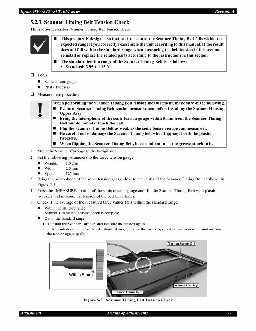
Adjustment Details of Adjustments 77
Epson WF-7520/7510/7010 series Revision A
5.2.3 Scanner Timing Belt Tension Check
This section describes Scanner Timing Belt tension check.
Tools
Sonic tension gauge
Plastic tweezers
Measurement procedure
1. Move the Scanner Carriage to the 0-digit side.
2. Set the following parameters to the sonic tension gauge:
Weight: 1.0 g/m
Width: 2.5 mm
Span: 527 mm
3. Bring the microphone of the sonic tension gauge close to the center of the Scanner Timing Belt as shown in
Figure 5-3.
4. Press the “MEASURE” button of the sonic tension gauge and flip the Scanner Timing Belt with plastic
tweezers and measure the tension of the belt three times.
5. Check if the average of the measured three values falls within the standard range.
Within the standard range:
Scanner Timing Belt tension check is complete.
Out of the standard range:
1. Reinstall the Scanner Carriage, and measure the tension again.
2. If the result does not fall within the standard range, replace the torsion spring 43.6 with a new one and measure
the tension again. (p 62)
Figure 5-3. Scanner Timing Belt Tension Check
This product is designed so that each tension of the Scanner Timing Belt falls within the
expected range if you correctly reassemble the unit according to this manual. If the result
does not fall within the standard range when measuring the belt tension in this section,
reinstall or replace the related parts according to the instructions in this section.
The standard tension range of the Scanner Timing Belt is as follows:
• Standard: 3.95 ± 1.15 N
When performing the Scanner Timing Belt tension measurement, make sure of the following.
Perform Scanner Timing Belt tension measurement before installing the Scanner Housing Upper Assy.
Bring the microphone of the sonic tension gauge within 5 mm from the Scanner Timing Belt but do not let it touch the belt.
Flip the Scanner Timing Belt as weak as the sonic tension gauge can measure it.
Be careful not to damage the Scanner Timing belt when flipping it with the plastic tweezers.
When flipping the Scanner Timing Belt, be careful not to let the grease attach to it.
Scanner Timing Belt
Scanner Carriage
Torsion Spring 43.6

Adjustment Details of Adjustments 78
Epson WF-7520/7510/7010 series Revision A
5.2.4 MAC Address Setting
Setting procedure
1. After replacing the Main Board, note down the MAC address written on a label on the Shield Plate Lower.
2. Reassemble the printer, and connect the printer and the PC with the USB cable.
3. Start the Adjustment Program.
4. Select the “Initial Setting” from the menu. The initial setting screen appears.
5. Enter the last six digits of MAC address into the MAC address entry field, and click the MAC Address input
button. (Enter the address again into the second entry field to confirm it.)
6. Select the network status sheet from the printer’s control panel, and print the sheet. Check the MAC address
printed on the sheet to see if it is correct.
Figure 5-5. MAC Address Setting Screen
This setting is not necessary when the data in EEPROM on the Main Board can be read out.
To avoid a conflict of MAC address on a network, make sure to correctly follow the MAC
address setting flowchart given on the following.
The user should be notified of the change of MAC address because of the following
reasons.
• If the user has set the printer’s MAC address on a router, the repaired printer with a
new MAC address cannot be connected to the network.
• The default printer name on a network consists of “EPSON” and the last six digits of the
MAC address. Therefore, the printer name becomes different from the previous one.
You are required to enter the last six digits of the MAC address (xx:yy:zz) on the
Adjustment Program.
MAC address example: 00:00:48:xx:yy:zz
(“xx, yy, zz” represents a value unique to each printer)
Figure 5-4. MAC Address Label
MAC Address Label
Last six digits of MAC address

CHAPTER 6
MAINTENANCE

Maintenance Overview 80
Epson WF-7520/7510/7010 series Revision A
6.1 Overview
This section provides information to maintain the printer in its optimum condition.
6.1.1 CleaningExcept for the printhead, there are no other mechanical parts or units that require periodic cleaning. However, if
need arises, clean the component observing the following instructions.
Instructions for cleaning
Exterior parts such as housing
Wipe dirt off with a soft clean cloth moistened with water. For glossy or transparent parts, use of unwoven cloth is
recommended to avoid scratching those parts.
Inside of the printer
Remove paper dust with a vacuum cleaner.
Rubber or plastic rollers such as an Pickup Roller used to feed paper
If paper dust adhered to the rollers decreases the frictional force of the rollers and the rollers cannot properly feed
paper, wipe off the paper dust with a soft cloth moistened with diluted alcohol.
Instructions for cleaning ink stains
Wipe the stains off with a cloth wrung out of diluted alcohol.
6.1.2 LubricationThe type and amount of the grease used to lubricate the printer parts are determined based on the results of the
internal evaluations. Therefore, refer to "6.2 Lubrication Points and Instructions (p81)" for the repairing
procedures below, and apply the specified type and amount of the grease to the specified part of the printer
mechanism.
Grease
Tools
Note *: Use tools whose specifications are specified in "6.2 Lubrication Points and Instructions (p81)".
Do not use alcohol for cleaning the transparent parts. Doing so may cause them to get
cloudy.
When wiping paper dust off the Pickup Roller/Middle Roller, be careful not to rub
against the surface asperity.
To minimize the effect on the parts, use diluted alcohol such as 70% diluted ether.
After using alcohol for cleaning, make sure to wipe the part off with a soft dry dust-free
cloth to remove alcohol traces fully.
Type Name EPSON Part Code Supplier
Grease G-26 1080614 EPSON
Grease G-45 1033657 EPSON
Grease G-71 1480655 EPSON
Grease G-72 1409258 EPSON
Grease G-74 1409257 EPSON
Name Availability EPSON Part Code
Injector O * ---
Brush O * ---

Ep
son
WF
-752
0/7
51
0/7
010
ser
ies
Rev
isio
n A
Ma
inte
na
nce
Lu
bri
cati
on
Po
ints
an
d I
nst
ruct
ion
s81
6.2
L
ub
rica
tio
n P
oin
ts a
nd
In
stru
ctio
ns
Fig
ure
6-1
.L
ub
rica
tio
n o
f th
e D
riv
en P
ull
ey
/ D
riv
en P
ull
ey H
old
er
<L
ub
rica
tio
n P
oin
t>
1. B
eari
ng o
f th
e D
riven
Pull
ey H
old
er (
x2)
2. C
onta
ct p
oin
ts (
x8)
on
the
Dri
ven
Pu
lley
Ho
lder
wit
h t
he
Mai
n
Fra
me
3. S
haf
t h
ole
of
the
Dri
ven
Pu
lley
<T
yp
e>
G-7
1
<A
ppli
cati
on A
mount>
1 m
m x
1 m
m
<R
emar
ks>
App
ly w
ith
in
ject
or.
1. A
fter
att
achin
g t
he
Dri
ven
Pu
lley
to
th
e
Dri
ven
Pull
ey H
old
er,
wip
e th
e g
reas
e th
at r
un
s
off
.
Dri
ven
Pu
lley
Ho
lder
Ba
ck
Dri
ven
Pu
lley
Ho
lder
Fro
nt
Dri
ven
Pu
lley
2.
Ap
pli
cati
on
Poin
t
1.
Ap
pli
cati
on
Poin
t
3.
Ap
pli
cati
on
Poin
t
Fig
ure
6-2
.L
ub
rica
tion
of
the
Pap
er
Gu
ide
Fro
nt
Ass
y
<L
ub
rica
tio
n P
oin
t>1
. R
ibs
(x3)
on t
he
Pap
er
Guid
e F
ront
Ass
y(C
onta
ct p
oin
ts w
ith th
e P
F
Rol
ler
and
Spu
r G
ear
12)
2.
Shaf
t of
the
Pap
er G
uid
e F
ront A
ssy (
Conta
ct p
oin
t w
ith
th
e C
om
bin
atio
n
Gea
r 16.1
0.4
)3
. S
haf
ts (
x5)
of
the
Pap
er
Gu
ide
Fro
nt
Ass
y
(Co
nta
ct p
oin
ts w
ith
th
e S
pu
r G
ear
11
.2 a
nd
C
lutc
h G
ear)
<T
ype>
G-7
1
<A
ppli
cati
on
Am
ou
nt>
1.
3 m
m x
1 m
m x
hal
f ci
rcle
2.
3 m
m3
. 1
mm
x 2
mm
<R
emar
ks>
Apply
wit
h i
nje
ctor.
1.
Aft
er i
nst
alli
ng t
he
PF
R
oll
er, r
ota
te it
clo
ckw
ise
and c
ounte
rclo
ckw
ise
two t
urn
s ea
ch, an
d
confi
rm t
he
gre
ase
is
atta
ched
even
ly o
n t
he
circ
um
fere
nce
of
the
PF
R
oll
er a
nd S
pur
Gea
r 12.
Pap
er G
uid
e F
ron
t A
ssy
2. A
pp
lica
tio
n P
oin
t
1. A
pp
lica
tio
n P
oin
t
3. A
pp
lica
tio
n P
oin
t
Fig
ure
6-3
.L
ub
ric
ati
on
of
the
Pa
per
Gu
ide
Fro
nt
Ass
y (
EJ
Ro
ller
)
<L
ub
rica
tio
n P
oin
t>
1. R
ibs
(x3
) o
n t
he
Pap
er
Guid
e F
ront
Ass
y
(Co
nta
ct p
oin
ts w
ith
th
e
EJ
Ro
ller
)
2. S
haf
t of
the
EJ
Roll
er
(x2
)
<T
yp
e>
1. G
-74
2. G
-71
<A
ppli
cati
on A
mount>
1. 0
.04
g x
3 p
oin
ts
2.
1 m
m x
3 m
m
<R
emar
ks>
Sti
r G
-74
bef
ore
use
.
1. A
pp
ly w
ith b
rush
an
d
wip
e th
e g
reas
e th
at r
un
s
off
fro
m t
he
rib
s.
2. A
pp
ly w
ith i
nje
cto
r
wh
ile
rota
tin
g t
he
EJ
Ro
ller
.
EJ
Ro
ller
Pap
er
Gu
ide
Fro
nt
Ass
y
2.
Ap
pli
ca
tio
n P
oin
t
1.
Ap
pli
ca
tio
n P
oin
t
Fig
ure
6-4
.L
ub
rica
tio
n o
f th
e P
F R
oll
er G
rou
nd
ing S
pri
ng
Fig
ure
6-5
.L
ub
rica
tio
n o
f th
e M
ain
Fra
me
<L
ubri
cati
on P
oin
t>
Co
nta
ct p
oin
t bet
wee
n t
he
PF
Roll
er a
nd t
he
PF
Ro
ller
Gro
un
din
g S
pri
ng
<T
ype>
G-7
1
<A
pp
lica
tio
n A
mo
un
t>
3 m
m x
7 m
m
<R
emar
ks>
Apply
wit
h i
nje
ctor.
Ap
pli
ca
tio
n P
oin
t
PF
Roll
er G
rou
nd
ing S
pri
ng
PF
Ro
ller
<L
ub
rica
tio
n P
oin
t>
Conta
ct p
oin
ts (
x4)
bet
wee
n t
he
Mai
n F
ram
e
and
th
e D
/E L
ever
<T
yp
e>
G-7
1
<A
ppli
cati
on A
mount>
0.5
mm
x 1
0 m
m
<R
emar
ks>
Ap
ply
wit
h b
rush
.
Ma
in F
ram
e
D/E
Lev
er
Ap
pli
cati
on
Poin
t
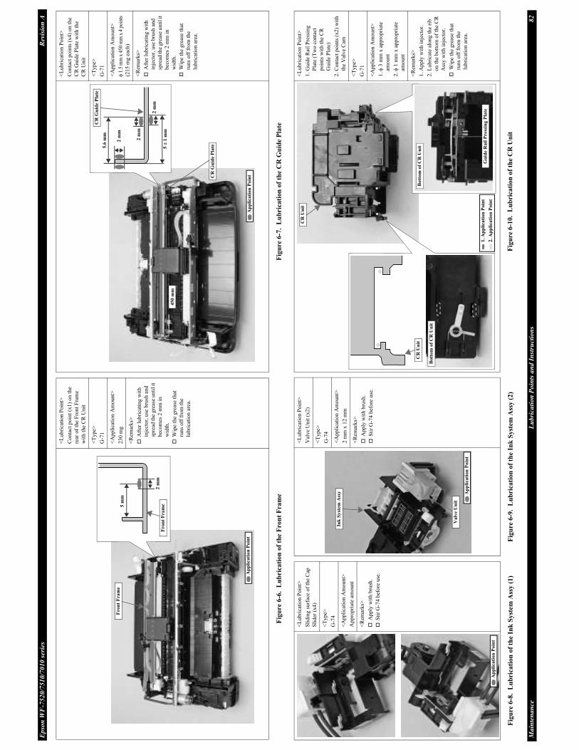
Ep
son
WF
-752
0/7
51
0/7
010
ser
ies
Rev
isio
n A
Ma
inte
na
nce
Lu
bri
cati
on
Po
ints
an
d I
nst
ruct
ion
s82
Fig
ure
6-6
.L
ub
rica
tio
n o
f th
e F
ron
t F
ram
e
<L
ubri
cati
on P
oin
t>
Co
nta
ct p
oin
t (x
1)
on
th
e
rear
of
the
Fro
nt
Fra
me
wit
h t
he
CR
Un
it
<T
yp
e>
G-7
1
<A
pp
lica
tion A
mount>
23
0 m
g
<R
emar
ks>
Aft
er l
ub
rica
tin
g w
ith
inje
ctor,
use
bru
sh a
nd
spre
ad th
e g
reas
e u
nti
l it
bec
om
es 2
mm
in
wid
th.
Wip
e th
e g
reas
e th
at
run
s off
fro
m t
he
lubri
cati
on a
rea.
5 m
m
2 m
mF
ron
t F
ram
e
Fro
nt
Fra
me
Ap
pli
cati
on
Poin
t
Fig
ure 6
-7.
Lu
bric
ati
on
of
the C
R G
uid
e P
late
<L
ub
rica
tio
n P
oin
t>
Co
nta
ct p
oin
ts (
x4
) o
n t
he
CR
Guid
e P
late
wit
h t
he
CR
Un
it
<T
ype>
G-7
1
<A
pp
lica
tio
n A
mo
unt>
1.5
mm
x 4
50 m
m x
4 p
oint
s
(215 m
g e
ach)
<R
emar
ks>
Aft
er l
ub
rica
tin
g w
ith
inje
cto
r, u
se b
rush
an
d
spre
ad th
e g
reas
e u
nti
l it
bec
om
es 2
mm
in
wid
th.
Wip
e th
e g
reas
e th
at
run
s o
ff f
rom
th
e
lub
rica
tio
n a
rea.
45
0 m
m
2 m
m
5.6
mm
2 m
m
5 ±
1 m
m
2 m
m
CR
Gu
ide
Pla
te
CR
Gu
ide
Pla
te
Ap
pli
cati
on
Po
int
Fig
ure
6-8
.L
ub
rica
tio
n o
f th
e In
k S
yst
em
Ass
y (
1)
Fig
ure
6-9
.L
ub
ric
ati
on
of
the I
nk
Syst
em A
ssy (
2)
<L
ub
rica
tio
n P
oin
t>
Sli
din
g s
urf
ace
of
the
Cap
Sli
der
(x
4)
<T
yp
e>
G-7
4
<A
ppli
cati
on A
mount>
Ap
pro
pri
ate
amou
nt
<R
emar
ks>
Ap
ply
wit
h b
rush
.
Sti
r G
-74 b
efore
use
.
Ap
pli
cati
on
Po
int
<L
ub
rica
tio
n P
oin
t>
Val
ve
Unit
(x2)
<T
ype>
G-7
4
<A
pp
lica
tio
n A
mou
nt>
2 m
m x
12
mm
<R
emar
ks>
Apply
wit
h b
rush
.
Sti
r G
-74 b
efore
use
.
Va
lve
Un
it
Ink
Syst
em A
ssy A
pp
lica
tio
n P
oin
t
Fig
ure 6
-10.
Lu
bric
ati
on
of
the C
R U
nit
<L
ub
rica
tio
n P
oin
t>
1.
Gu
ide
Rai
l P
ress
ing
Pla
te (
Tw
o c
onta
ct
poin
ts w
ith
th
e C
R
Gu
ide
Pla
te)
2. C
onta
ct p
oin
ts (
x2)
wit
h
the
Val
ve
Cam
<T
ype>
G-7
1
<A
pp
lica
tio
n A
mo
unt>
1.
3 m
m x
ap
pro
pri
ate
amo
un
t
2.
1 m
m x
ap
pro
pri
ate
amo
un
t
<R
emar
ks>
1.
Apply
wit
h i
nje
ctor.
2.
Lubri
cate
alo
ng t
he
rib
on
th
e b
ott
om
of
the
CR
Ass
y w
ith i
nje
ctor.
Wip
e th
e g
reas
e th
at
run
s o
ff f
rom
th
e
lub
rica
tio
n a
rea.
Bo
ttom
of
CR
Un
it
Gu
ide R
ail
Pre
ssin
g P
late
Bott
om
of
CR
Un
it
CR
Un
it
CR
Un
it
2. A
pp
lica
tio
n P
oin
t
1. A
pp
lica
tio
n P
oin
t

Ep
son
WF
-752
0/7
51
0/7
010
ser
ies
Rev
isio
n A
Ma
inte
na
nce
Lu
bri
cati
on
Po
ints
an
d I
nst
ruct
ion
s83
Fig
ure
6-1
1.
Lu
bri
cati
on
of
the
Du
ple
x U
nit
<L
ubri
cati
on P
oin
t>
Shaf
t of
the
Mid
dle
Roll
er
<T
yp
e>
G-7
1
<A
pp
lica
tion A
mount>
2 m
m x
4 m
m
<R
emar
ks>
Ap
ply
wit
h i
nje
cto
r.
Mid
dle
Roll
er
Ap
pli
cati
on
Poin
t
Du
ple
x U
nit
Fig
ure
6-1
2.
Lu
bric
ati
on
of
the
Pap
er S
top
per
Ass
y 1
st/2
nd
<L
ub
rica
tio
n P
oin
t>
1.
Gro
oves
of
the
slid
er
bas
e (c
onta
ct p
oin
ts w
ith
the
Cam
Sli
der
)
2.
Cam
Sli
der
<T
ype>
1.
G-7
2
2.
G-7
1
<A
ppli
cati
on
Am
ou
nt>
1.
0.5
g
0.1
g x
16
po
ints
2.
Ap
pro
pri
ate
amo
un
t
(0.0
05
g
0.0
01
g)
<R
emar
ks>
Ap
ply
wit
h b
rush
.
1.
Sta
rt l
ub
rica
tio
n 7
mm
fro
m t
he
ou
ter
end
of
each
gro
ov
e ro
w o
f th
e
Sli
der
Bas
e an
d
lub
rica
te 7
mm
at
2
po
ints
per
gro
ov
e (1
6
poin
ts i
n t
ota
l).
Aft
er
lub
rica
tio
n, at
tach
th
e
Cam
Sli
der
to
th
e S
lid
er
Bas
e an
d m
ove
the
Cam
Sli
der
bac
k a
nd f
ort
h
thre
e ti
mes
to a
pply
the
gre
ase
even
ly.
7 m
m
7 m
m
Sli
der
Ba
se
Ca
m S
lid
er
Ca
m S
lid
erP
ap
er S
top
per
Ass
y2
. A
pp
lica
tio
n P
oin
t
1.
Ap
pli
cati
on
Poin
t
Fig
ure 6
-13.
Lu
bri
cati
on
of
the
AD
F P
ap
er G
uid
e U
pp
er
Ass
y
<L
ubri
cati
on P
oin
t>
LD
shaf
t of
the
AD
F P
aper
Guid
e U
pper
Ass
y (
x4)
<T
ype>
G-7
1
<A
pp
lica
tion A
mount>
1 m
m x
2 m
m
<R
emar
ks>
Ap
ply
wit
h i
nje
cto
r.
LD
Sh
aft
Insi
de
of
AD
F P
ap
er G
uid
e U
pp
er A
ssy
AD
F P
ap
er G
uid
e U
pp
er A
ssy
Ap
pli
ca
tio
n P
oin
t
Fig
ure
6-1
4.
Lu
bri
cati
on
of
the
Sca
nn
er U
nit
<L
ub
rica
tio
n P
oin
t>
1.
Com
bin
atio
n G
ear
21.6
.10
.8 M
ou
nti
ng
Sh
aft,
Co
mb
inat
ion
Gea
r 25.2
.9.0
553
Mounti
ng S
haf
t an
d
Sca
nner
Dri
ven
Pull
ey
Mounti
ng S
haf
t (x
2
each
)
2.
Guid
e ra
il o
f th
e
Sca
nner
Housi
ng L
ow
er
(x3
)
<T
ype>
1.
G-2
6
2.
G-4
5
<A
pp
lica
tio
n A
mo
unt>
1.
1 m
m x
2 m
m
2.
0.0
3 g
x 3
po
ints
<R
emar
ks>
1.
App
ly w
ith
in
ject
or.
2.
Aft
er l
ub
rica
tin
g w
ith
inje
ctor,
use
bru
sh a
nd
spre
ad t
he
gre
ase
all
over
th
e g
uid
e ra
il i
n t
he
ord
er i
nd
icat
ed i
n t
he
figure
.
Gu
ide
rail
Cen
ter
1
23
Sca
nn
er H
ou
sin
g L
ow
er
Sca
nn
er D
riv
en P
ull
ey
Mo
un
tin
g S
ha
ftL
eft
Rig
ht
Co
mb
ina
tio
n G
ear
25
.2.9
.055
3 M
ou
nti
ng
Sh
aft
Co
mb
ina
tio
n G
ear
21
.6.1
0.8
Mou
nti
ng
Sh
aft
2. A
pp
lica
tio
n P
oin
t
1. A
pp
lica
tio
n P
oin
t
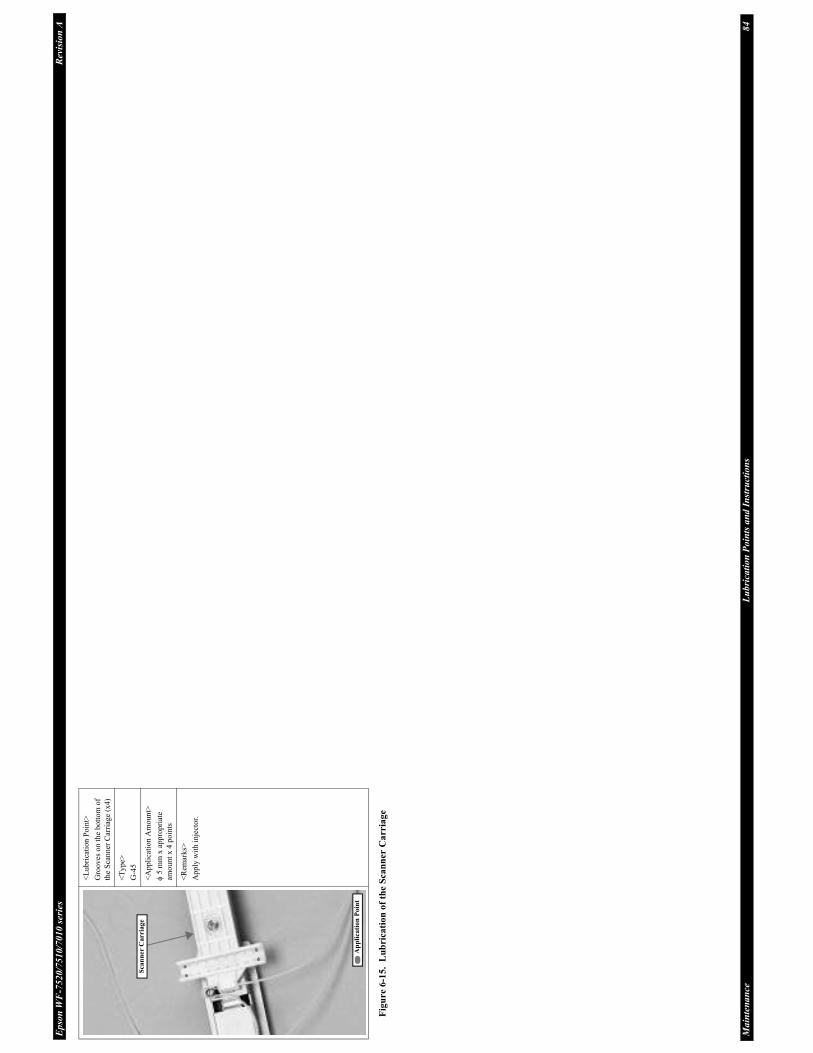
Ep
son
WF
-752
0/7
51
0/7
010
ser
ies
Rev
isio
n A
Ma
inte
na
nce
Lu
bri
cati
on
Po
ints
an
d I
nst
ruct
ion
s84
Fig
ure 6
-15.
Lu
bric
ati
on
of
the S
can
ner C
arria
ge
<L
ub
rica
tio
n P
oin
t>
Gro
ov
es o
n t
he
bo
tto
m o
f
the
Sca
nner
Car
riag
e (x
4)
<T
yp
e>
G-4
5
<A
ppli
cati
on A
mount>
5 m
m x
app
rop
riat
e
amo
un
t x
4 p
oin
ts
<R
emar
ks>
Ap
ply
wit
h i
nje
cto
r.
Sca
nn
er
Ca
rria
ge
Ap
pli
cati
on
Po
int