Embed Size (px)
Citation preview

EPS-8 and EPS-9 ElectrostaticPower Supplies
Customer Product ManualPart 107068C
Issued 11/01
NORDSON CORPORATION AMHERST, OHIO USA
CAPPROVED
USFM
For parts and technical support, call the Industrial CoatingSystems Customer Support Center at (800) 433-9319 or
contact your local Nordson representative.
This document is subject to change without notice.Check http://emanuals.nordson.com for the latest version.

Part 107068C � 2001 Nordson Corporation
Contact UsNordson Corporation welcomes requests for information, comments, andinquiries about its products. General information about Nordson can befound on the Internet using the following address:http://www.nordson.com.Address all correspondence to:
Nordson CorporationAttn: Customer Service555 Jackson StreetAmherst, OH 44001
NoticeThis is a Nordson Corporation publication which is protected by copyright.Original copyright date XXXX. No part of this document may bephotocopied, reproduced, or translated to another language without theprior written consent of Nordson Corporation. The information containedin this publication is subject to change without notice.
Trademarks
Nordson and the Nordson logo are registered trademarks of NordsonCorporation.

Table of Contents i
� 2001 Nordson CorporationAll rights reserved
107068CIssued 11/01
Manual 9-13
Table of Contents
1. Introduction 1-1. . . . . . . . . . . . . . . . . . . . . . . . . . . . . . . . . . . . . . . . . . . . . .
2. Safety Symbols 1-1. . . . . . . . . . . . . . . . . . . . . . . . . . . . . . . . . . . . . . . . . . .
3. Qualified Personnel 1-3. . . . . . . . . . . . . . . . . . . . . . . . . . . . . . . . . . . . . . .
4. Intended Use 1-3. . . . . . . . . . . . . . . . . . . . . . . . . . . . . . . . . . . . . . . . . . . . .
5. Installation 1-4. . . . . . . . . . . . . . . . . . . . . . . . . . . . . . . . . . . . . . . . . . . . . . .
6. Operation 1-5. . . . . . . . . . . . . . . . . . . . . . . . . . . . . . . . . . . . . . . . . . . . . . . .
7. Less-Obvious Dangers 1-7. . . . . . . . . . . . . . . . . . . . . . . . . . . . . . . . . . . .
8. Action in the Event of a System or Component Malfunction 1-8. . . . .
9. Maintenance and Repair 1-8. . . . . . . . . . . . . . . . . . . . . . . . . . . . . . . . . . .
10. Material and Solvent Precautions 1-10. . . . . . . . . . . . . . . . . . . . . . . . . . .
11. Disposal 1-13. . . . . . . . . . . . . . . . . . . . . . . . . . . . . . . . . . . . . . . . . . . . . . . .
12. Safety Labels 1-15. . . . . . . . . . . . . . . . . . . . . . . . . . . . . . . . . . . . . . . . . . .
1. Introduction 2-1. . . . . . . . . . . . . . . . . . . . . . . . . . . . . . . . . . . . . . . . . . . . . .
2. Components 2-2. . . . . . . . . . . . . . . . . . . . . . . . . . . . . . . . . . . . . . . . . . . . .
3. Features 2-5. . . . . . . . . . . . . . . . . . . . . . . . . . . . . . . . . . . . . . . . . . . . . . . . .
4. Specifications 2-5. . . . . . . . . . . . . . . . . . . . . . . . . . . . . . . . . . . . . . . . . . . .
1. Installing the Power Supply 3-1. . . . . . . . . . . . . . . . . . . . . . . . . . . . . . . . .
2. Setting the Voltage 3-3. . . . . . . . . . . . . . . . . . . . . . . . . . . . . . . . . . . . . . . .
3. Making Terminal Block Connections A–I and 1–4 3-3. . . . . . . . . . . . . .
4. Using Terminal Block Connections for PLC Interface 3-7. . . . . . . . . . .
5. Installing the Electrostatic Cable 3-10. . . . . . . . . . . . . . . . . . . . . . . . . . .
6. Using the Microammeter 3-11. . . . . . . . . . . . . . . . . . . . . . . . . . . . . . . . . .
1. Operating the EPS8/9 4-1. . . . . . . . . . . . . . . . . . . . . . . . . . . . . . . . . . . . .
Safety
Description
Installation
Operation

Table of Contentsii
� 2001 Nordson CorporationAll rights reserved
107068CIssued 11/01
Manual 9-13
1. Introduction 5-1. . . . . . . . . . . . . . . . . . . . . . . . . . . . . . . . . . . . . . . . . . . . . .
Troubleshooting Electrical Problems 5-2. . . . . . . . . . . . . . . . . . . . . . .
Input Voltage Calibration 5-6. . . . . . . . . . . . . . . . . . . . . . . . . . . . . . . . .
2. Wiring Diagrams 5-8. . . . . . . . . . . . . . . . . . . . . . . . . . . . . . . . . . . . . . . . . .
1. Disassembling the Power Supply 6-1. . . . . . . . . . . . . . . . . . . . . . . . . . . .
2. Removing the Multiplier Assembly 6-2. . . . . . . . . . . . . . . . . . . . . . . . . . .
3. Installing the Multiplier Assembly 6-4. . . . . . . . . . . . . . . . . . . . . . . . . . . .
4. Assembling the Power Supply 6-7. . . . . . . . . . . . . . . . . . . . . . . . . . . . . .
5. Testing the Display 6-7. . . . . . . . . . . . . . . . . . . . . . . . . . . . . . . . . . . . . . . .
1. Introduction 7-1. . . . . . . . . . . . . . . . . . . . . . . . . . . . . . . . . . . . . . . . . . . . . .
Using the Illustrated Parts List 7-1. . . . . . . . . . . . . . . . . . . . . . . . . . . .
EPS8 Standard Parts 7-2. . . . . . . . . . . . . . . . . . . . . . . . . . . . . . . . . . .
EPS9 Standard Parts 7-6. . . . . . . . . . . . . . . . . . . . . . . . . . . . . . . . . . .
Cable Cleaning Kit 7-10. . . . . . . . . . . . . . . . . . . . . . . . . . . . . . . . . . . . .
Troubleshooting
Repair
Parts

� 2001 Nordson CorporationAll rights reserved
Issued 11/95 A1EN−03−[SF−LIQD]−3
Section 1
Safety

Safety1-0
� 2001 Nordson CorporationAll rights reserved
Issued 11/95A1EN−03−[SF−LIQD]−3
Safety 1-1
� 2001 Nordson CorporationAll rights reserved
Issued 11/95 A1EN−03−[SF−LIQD]−3
Section 1Safety
This section contains general safety instructions for using your Nordsonequipment. Task- and equipment-specific warnings are included in othersections of this manual where appropriate. Note all warnings and followall instructions carefully. Failure to do so may result in personal injury,death, or property damage.
To use this equipment safely,
� read and become familiar with the general safety instructionsprovided in this section of the manual before installing, operating,maintaining, or repairing this equipment.
� read and carefully follow the instructions given throughout this manualfor performing specific tasks and working with specific equipment.
� store this manual within easy reach of personnel installing, operating,maintaining, or repairing this equipment.
� follow all applicable safety procedures required by your company,industry standards, and government or other regulatory agencies.Refer to the National Fire Protection Association (NFPA) standard 33and to federal, state, regulatory agency, and local codes for rules andregulations covering installation and operation of spray systems.
� obtain and read Material Safety Data Sheets (MSDS) for all materialsused.
Become familiar with the safety symbols presented in this section. Thesesymbols will alert you to safety hazards and conditions that may result inpersonal injury, death, or property and equipment damage.
WARNING: Failure to observe this warning may result inpersonal injury, death, or equipment damage.
1. Introduction
2. Safety Symbols
Safety1-2
� 2001 Nordson CorporationAll rights reserved
Issued 11/95A1EN−03−[SF−LIQD]−3
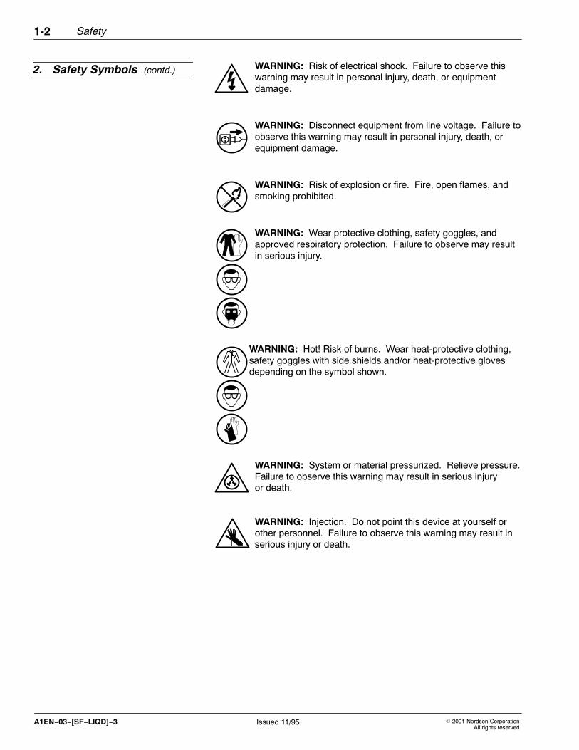
WARNING: Risk of electrical shock. Failure to observe thiswarning may result in personal injury, death, or equipmentdamage.
WARNING: Disconnect equipment from line voltage. Failure toobserve this warning may result in personal injury, death, orequipment damage.
WARNING: Risk of explosion or fire. Fire, open flames, andsmoking prohibited.
WARNING: Wear protective clothing, safety goggles, andapproved respiratory protection. Failure to observe may resultin serious injury.
WARNING: Hot! Risk of burns. Wear heat-protective clothing,safety goggles with side shields and/or heat-protective glovesdepending on the symbol shown.
WARNING: System or material pressurized. Relieve pressure.Failure to observe this warning may result in serious injuryor death.
WARNING: Injection. Do not point this device at yourself orother personnel. Failure to observe this warning may result inserious injury or death.
2. Safety Symbols (contd.)

Safety 1-3
� 2001 Nordson CorporationAll rights reserved
Issued 11/95 A1EN−03−[SF−LIQD]−3
CAUTION: Failure to observe may result in equipmentdamage.
CAUTION: Hot surface. Failure to observe may result inburns.
“Qualified personnel” is defined here as individuals who thoroughlyunderstand the equipment and its safe operation, maintenance, andrepair. Qualified personnel are physically capable of performing therequired tasks, familiar with all relevant safety rules and regulations, andhave been trained to safely install, operate, maintain, and repair theequipment. It is the responsibility of the company operating thisequipment to see that its personnel meet these requirements.
WARNING: Use of this equipment in ways other thandescribed in this manual may result in personal injury, death, orproperty and equipment damage. Use this equipment only asdescribed in this manual.
Nordson Corporation cannot be responsible for injuries or damagesresulting from nonstandard, unintended applications of its equipment.This equipment is designed and intended only for the purpose describedin this manual. Uses not described in this manual are consideredunintended uses and may result in serious personal injury, death, orproperty damage. Unintended uses may result from taking the followingactions:
� making changes to equipment that have not been recommended ordescribed in this manual or using parts that are not genuine Nordsonreplacement parts
� failing to make sure that auxiliary equipment complies with approvalagency requirements, local codes, and all applicable safety standards
� using materials or auxiliary equipment that are inappropriate orincompatible with your Nordson equipment
� allowing unqualified personnel to perform any task
2. Safety Symbols (contd.)
3. Qualified Personnel
4. Intended Use
Safety1-4
� 2001 Nordson CorporationAll rights reserved
Issued 11/95A1EN−03−[SF−LIQD]−3
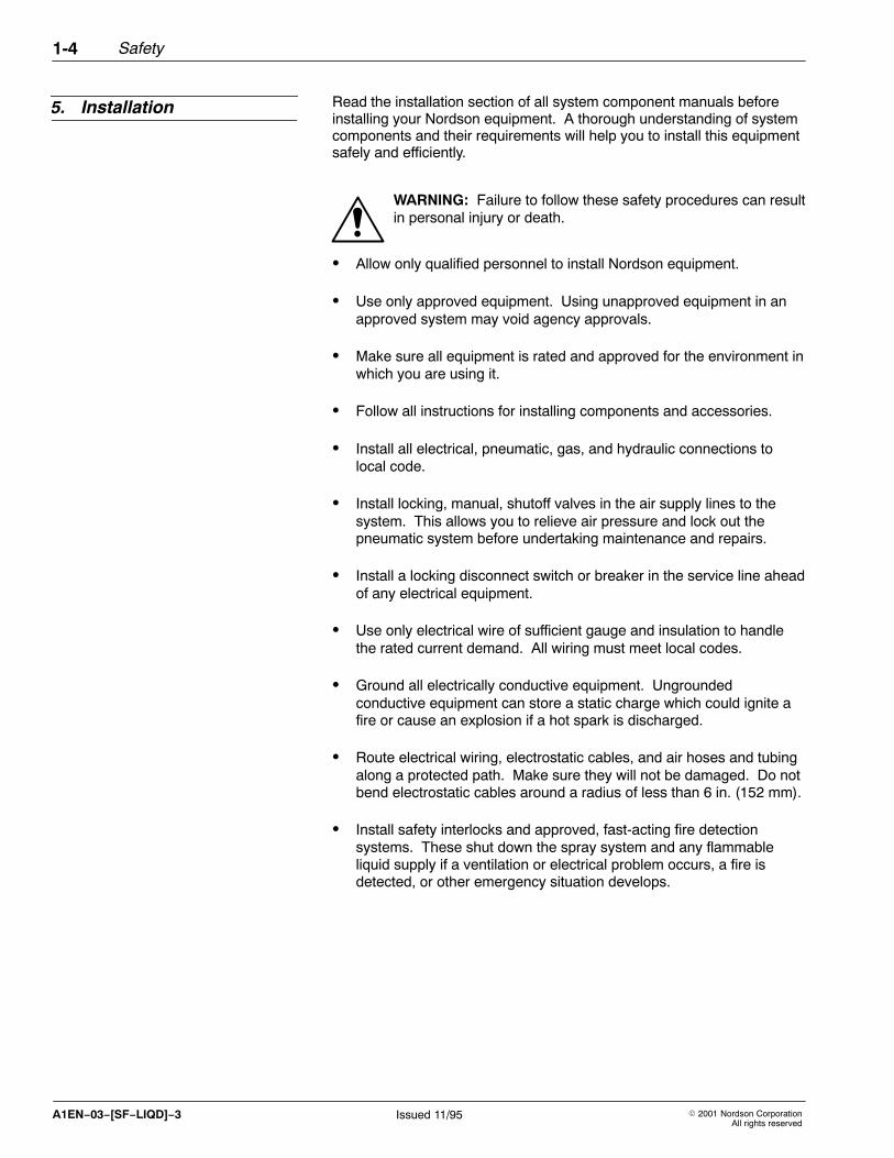
Read the installation section of all system component manuals beforeinstalling your Nordson equipment. A thorough understanding of systemcomponents and their requirements will help you to install this equipmentsafely and efficiently.
WARNING: Failure to follow these safety procedures can resultin personal injury or death.
� Allow only qualified personnel to install Nordson equipment.
� Use only approved equipment. Using unapproved equipment in anapproved system may void agency approvals.
� Make sure all equipment is rated and approved for the environment inwhich you are using it.
� Follow all instructions for installing components and accessories.
� Install all electrical, pneumatic, gas, and hydraulic connections tolocal code.
� Install locking, manual, shutoff valves in the air supply lines to thesystem. This allows you to relieve air pressure and lock out thepneumatic system before undertaking maintenance and repairs.
� Install a locking disconnect switch or breaker in the service line aheadof any electrical equipment.
� Use only electrical wire of sufficient gauge and insulation to handlethe rated current demand. All wiring must meet local codes.
� Ground all electrically conductive equipment. Ungroundedconductive equipment can store a static charge which could ignite afire or cause an explosion if a hot spark is discharged.
� Route electrical wiring, electrostatic cables, and air hoses and tubingalong a protected path. Make sure they will not be damaged. Do notbend electrostatic cables around a radius of less than 6 in. (152 mm).
� Install safety interlocks and approved, fast-acting fire detectionsystems. These shut down the spray system and any flammableliquid supply if a ventilation or electrical problem occurs, a fire isdetected, or other emergency situation develops.
5. Installation

Safety 1-5
� 2001 Nordson CorporationAll rights reserved
Issued 11/95 A1EN−03−[SF−LIQD]−3
� Make sure the spray area floor is conductive to ground and that theoperator’s platform is grounded.
� Use only designated lifting points or lugs to lift and move heavyequipment. Always balance and block loads when lifting to preventshifting. Lifting devices must be inspected, certified, and rated for agreater weight than the equipment being lifted.
� Do not use unapproved fluid hoses. Solvents may cause them todeteriorate rapidly which may allow flammable or pressurized materialto escape.
� Protect components from damage, wear, and harsh environmentalconditions.
� Allow ample room for maintenance, material supply container drop-offand loading, panel accessibility, and cover removal.
� Protect equipment with safety devices as specified by applicablesafety regulations.
� If safety devices must be removed for installation, install themimmediately after the work is completed and check them for properfunctioning.
Only qualified personnel, physically capable of operating the equipmentand with no impairments to their judgement or reaction times, shouldoperate this equipment.
Read all component manuals before operating this equipment. Athorough understanding of system components and their operation willhelp you operate the system safely and efficiently.
� Use this equipment only in the environments for which it is rated. Donot operate this equipment in humid, flammable, or explosiveenvironments unless it has been rated for safe operation in theseenvironments.
� Before starting this equipment, check all safety interlocks,fire-detection systems, and protective devices such as panels andcovers. Make sure all devices are fully functional. Do not operate thesystem if these devices are not working properly. Do not deactivateor bypass automatic safety interlocks, locked-out electricaldisconnects, or pneumatic valves.
5. Installation (contd.)
6. Operation

Safety1-6
� 2001 Nordson CorporationAll rights reserved
Issued 11/95A1EN−03−[SF−LIQD]−3
� Know where EMERGENCY STOP buttons, shutoff valves, and fireextinguishers are located. Make sure they work. If a componentmalfunctions, shut down and lock out the equipment immediately.
� Before operating, make sure all conductive equipment, objects beingsprayed, and fluid containers are connected to a true earth ground.
� Never operate equipment with a known malfunction or leak.
� Never point handguns or applicator nozzles at yourself or otherpersons.
� Never touch exposed electrical connections on equipment while thepower is ON.
� Do not operate the equipment at pressures higher than the ratedmaximum working pressure of any component in the system.
� Shut off moving equipment before taking measurements or inspectingworkpieces.
� Know the pinch points, temperatures, pressures, and materialcomposition for all equipment that you are working with. Recognizepotential hazards associated with these and exercise appropriatecaution.
� Wear shoes with conductive soles, such as leather, or use groundingstraps to maintain a connection to ground when working with oraround electrostatic equipment.
� Do not wear or carry metallic objects (jewelry or tools) while workingwith or around electrostatic equipment. Ungrounded metal can storea static charge and cause harmful shocks.
� Maintain skin-to-metal contact between your hand and the gun handleto prevent shocks while operating manual electrostatic spray guns. Ifwearing gloves, cut away the palm or fingers.
� Shut off electrostatic power supplies and ground gun electrodesbefore making adjustments to powder spray guns.
� If you notice electrical arcing in a spray area, shut down the systemimmediately. An arc can cause a fire or explosion.
� Keep parts of the body or loose clothing away from rotating parts.Remove personal jewelry and cover or tie back long hair.
6. Operation (contd.)

Safety 1-7
� 2001 Nordson CorporationAll rights reserved
Issued 11/95 A1EN−03−[SF−LIQD]−3
� Wear National Institute of Occupational Safety and Health (NIOSH)approved respirators while operating spray equipment and whenperforming maintenance and cleaning tasks.
� Wear eye protection when operating spray equipment.
� Wear gloves and protective clothing to protect your skin frommaterials.
� Keep paint pumps, pressure pots, and containers of flammablecoating materials or solvents far enough away from spray booths toprevent their inclusion in a booth fire.
� Do not smoke in the spray area. A lit cigarette could ignite a fire orcause an explosion.
� Treat all high-pressure fittings and hoses as if they could leak.High-pressure compressed air can be injected under the skin andcause serious injury or death.
� Do not use materials that will corrode the equipment.
� Do not attempt to operate electrical equipment if standing water ispresent.
� Wash exposed skin frequently with soap and water, especially beforeeating or drinking. Do not use solvents to remove coating materialsfrom your skin.
Operators should also be aware of less-obvious dangers in the workplacethat often cannot be completely eliminated:
� exposed surfaces on the equipment which may be hot or have sharpedges and cannot be practically safeguarded
� electrical equipment which may remain energized after the equipmenthas been shut off
� vapors and materials which may cause allergic reactions or otherhealth problems
� automatic hydraulic, pneumatic equipment, or mechanical parts thatmay move without warning
� unguarded, moving mechanical assemblies
6. Operation (contd.)
7. Less-Obvious Dangers

Safety1-8
� 2001 Nordson CorporationAll rights reserved
Issued 11/95A1EN−03−[SF−LIQD]−3
Do not operate a system that contains malfunctioning components. If acomponent malfunctions, turn the system OFF immediately.
� Disconnect and lock out electrical power. Close and lock outhydraulic and pneumatic shutoff valves and relieve pressures.
� Allow only qualified personnel to make repairs. Repair or replace themalfunctioning component according to instructions provided in itsmanual.
Allow only qualified personnel to perform maintenance, troubleshooting,and repair tasks. Only persons who are properly trained and familiar withNordson equipment are permitted to service this equipment.
� Always wear appropriate protective clothing and use safety deviceswhen working on this equipment.
� Follow the recommended maintenance procedures in your equipmentmanuals.
� Do not service or adjust any equipment unless another person trainedin first aid and CPR is present.
� Disconnect, lock out, and tag electrical power at a disconnect orbreaker in the service line ahead of electrical equipment beforeservicing.
� Relieve air and fluid pressures before servicing equipment. Followthe specific instructions in this manual.
� Use only genuine Nordson replacement parts. Using unapprovedparts or making unapproved modifications to equipment may voidagency approvals and create safety hazards.
WARNING: Note the flash point of the cleaning solvent used.Only use controlled methods and equipment, such astemperature-controlled or explosion-protected heaters, to heatcleaning solvent. Observe explosion-prevention regulationsand follow applicable safety instructions.
� Refer to the MSDS before using solvents to clean this equipment.The MSDS will provide use, storage, and disposal information aboutthe solvent. Read this information carefully and follow instructions.
8. Action in the Event of aSystem or ComponentMalfunction
9. Maintenance and Repair

Safety 1-9
� 2001 Nordson CorporationAll rights reserved
Issued 11/95 A1EN−03−[SF−LIQD]−3
� Never use an open flame to clean the unit or components of the unit.
� Do not store flammable materials in the spray area or room. Keeppaint pumps, pressure pots, and containers of flammable coatingmaterials or solvents far enough away from spray booths to preventtheir inclusion in a booth fire. If a fire or explosion occurs, flammablematerials in the area will increase the chances and the extent ofpersonal injuries and property damage.
� Make sure that the room where you are working is sufficientlyventilated. Avoid breathing vapors over prolonged periods of time.
� Check interlock systems periodically to ensure their effectiveness.
WARNING: Operating faulty or electrostatic equipment ishazardous and can cause electrocution, fire, or explosion.Make resistance checks part of your periodic maintenanceprogram.
� Check all ground connections periodically with a megohm meter.Resistance to ground must not exceed one megohm. If sparks orarcing occur, shut down the system immediately.
� Connect all disconnected equipment ground cables and wires afterservicing the equipment. Ground all conductive equipment.
WARNING: Service lines connected to panel disconnectswitches will still be energized unless power is shut off atanother disconnect ahead of the panel. Make sure the power isoff before servicing. Wait 5 minutes for capacitors to dischargeafter shutting off the electrical power.
� Turn off the electrostatic power supply and ground the gun electrodebefore adjusting or cleaning the nozzles, fluid tips, or air caps.
� If a “power on” test is required, perform the test carefully and thenshut off and lock out power as soon as the test is over.
� Never troubleshoot the power supply without first disconnecting allexternal power supplies and discharging the high-voltage capacitorswith an insulated screwdriver.
� Ground electrodes and electrostatic cable ends before touching them.
9. Maintenance and Repair (contd.)

Safety1-10
� 2001 Nordson CorporationAll rights reserved
Issued 11/95A1EN−03−[SF−LIQD]−3
� Do not attempt to service electrical equipment if there is standingwater present. Do not service electrical equipment in a high-humidityenvironment.
� Use tools with insulated handles when working with electricalequipment.
� Keep high-voltage connection points clean and insulated withdielectric grease or oil.
� Do not attempt to service a moving piece of equipment. Shut off theequipment and lock out power. Secure equipment to preventuncontrolled movement.
WARNING: Hot! Risk of burns. Wear heat-protective clothing,eye protection with side shields and/or heat-protective gloves.
Heated materials may cause severe burns on contact. Remember thatsome materials, even solid materials, may retain heat for some time. Ifyou are burned by a heated material, immediately cool the affected skinwith lots of cool, clean water. Do not try to remove hot, melted materialfrom the skin. Seek immediate medical attention.
High-pressure fluids, unless they are safely contained, are extremelyhazardous. A jet of high-pressure fluid can act like a knife or needle,penetrate skin and muscle, and inject itself into your body. Injected fluidscan cause toxic poisoning.
Do not treat an injection injury as minor. Seek medical care immediately.Inform the medical staff at the hospital that you have an injection injuryand identify the fluid that was injected. If possible, give the doctor copiesof the MSDS for the injected fluid and for any additives, such as solvents,that are in the injected fluid.
Also, Nordson recommends that you carry a National Safety EquipmentManufacturers Association (NSEMA) wallet card to give to emergencymedical staff in the event of an injection injury. These cards are suppliedwith the equipment. Additional cards are available free from NordsonCorporation.
9. Maintenance and Repair (contd.)
10. Material and SolventPrecautions

Safety 1-11
� 2001 Nordson CorporationAll rights reserved
Issued 11/95 A1EN−03−[SF−LIQD]−3
WARNING: Injection hazard. Do not go near a known leak in ahose or fitting, and stay clear of all spray nozzles or orifices. Donot point an applicator at yourself or other personnel. Thehigh-pressure fluid stream can penetrate skin and inject fluidinto the body causing serious injury or death.
To prevent an injection injury, take some basic safety precautions whenoperating your equipment.
� Always handle spray applicators carefully. Do not point a pressurizedgun at yourself or other personnel.
� Never place hands, fingers, or other parts of your body directly over aspray nozzle or in front of a leak in a high-pressure system.
� Never “back-flush” the nozzles. Blocking a nozzle causes thehigh-pressure fluid to reverse direction and can lead to an injectioninjury.
� Always relieve system pressure before servicing equipment. Triggerall applicators and bleed off system pressure.
Halogenated hydrocarbon solvents can cause an explosion when usedwith aluminum components in a pressurized fluid pumping system(pumps, heaters, filters, valves, spray guns, and tanks). The explosioncould cause serious bodily injury, death, or substantial property damage.No available stabilizers will prevent this violent reaction from happening.
WARNING: Never use halogenated hydrocarbon solvents toclean aluminum parts or to flush any system. Cleaning agents,coatings and paints, or adhesives may contain halogenatedhydrocarbon solvents. Obtain and read the MSDS for eachmaterial and solvent being used.
� Use nonhalogenated solvents.
� Contact your solvent supplier to determine whether your existingmaterials and solvents contain halogenated hydrocarbons or to obtaina suitable, nonhalogenated hydrocarbon solvent for cleaning andflushing your system.
10. Material and SolventPrecautions (contd.)

Safety1-12
� 2001 Nordson CorporationAll rights reserved
Issued 11/95A1EN−03−[SF−LIQD]−3
� See Table 1-1. Check the labels on your solvent containers.Halogenated hydrocarbon solvents can be recognized if any of thefollowing elements are listed in the name of the product or as aningredient:
Element Symbol Prefix
Flourine F “Flouro-”
Chlorine Cl “Chloro-”
Bromine Br “Bromo-”
Iodine I “Iodo-”
If you are now using halogenated hydrocarbon solvents in pressurizedsystems with aluminum components, perform the following steps:
� Pump the system empty, shut off the pumps, and relieve the systempressure.
� Disassemble and inspect the system components. Replace anydamaged or corroded parts.
� Thoroughly clean all noncorroded parts with nonhalogenatedhydrocarbon.
� Contact your coatings, solvent, or adhesive supplier for anonhalogenated solvent to thoroughly flush the entire system beforeoperating it.
� If you must continue to use halogenated hydrocarbon solvents,consult your Nordson representative about compatible Nordsoncomponents.
10. Material and SolventPrecautions (contd.)
Safety 1-13
� 2001 Nordson CorporationAll rights reserved
Issued 11/95 A1EN−03−[SF−LIQD]−3
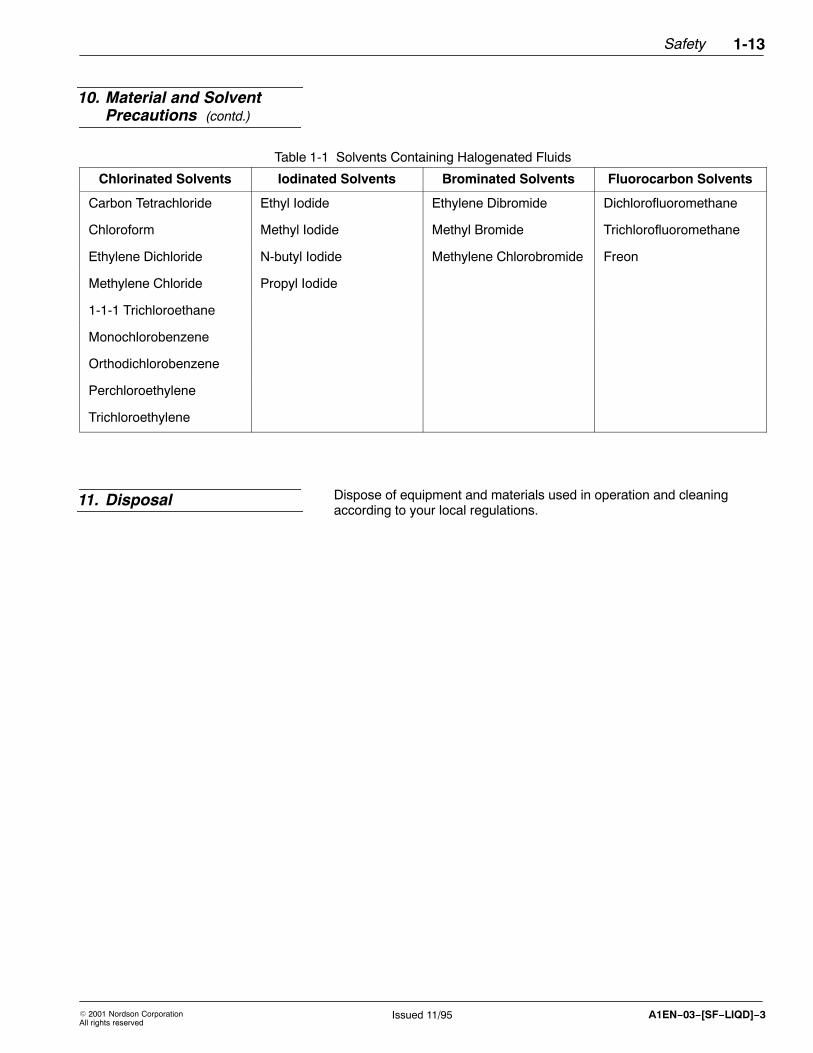
Table 1-1 Solvents Containing Halogenated Fluids
Chlorinated Solvents Iodinated Solvents Brominated Solvents Fluorocarbon Solvents
Carbon Tetrachloride Ethyl Iodide Ethylene Dibromide Dichlorofluoromethane
Chloroform Methyl Iodide Methyl Bromide Trichlorofluoromethane
Ethylene Dichloride N-butyl Iodide Methylene Chlorobromide Freon
Methylene Chloride Propyl Iodide
1-1-1 Trichloroethane
Monochlorobenzene
Orthodichlorobenzene
Perchloroethylene
Trichloroethylene
Dispose of equipment and materials used in operation and cleaningaccording to your local regulations.
10. Material and SolventPrecautions (contd.)
11. Disposal

Safety1-14
� 2001 Nordson CorporationAll rights reserved
Issued 11/95A1EN−03−[SF−LIQD]−3

Safety 1-15
� 2001 Nordson CorporationAll rights reserved
107068CIssued 11/01
Manual 9-13
Table 1-2 contains the text of the safety label on this equipment. Thesafety label is provided to help you operate and maintain your equipmentsafely. See Figure 1-1 for the location of the safety label.
Table 1-2 Safety Labels
Item Part Description
1. - - - - - - WARNING: Electrical discharge can be dangerous. Turn off this unit.Ground gun electrode and remove gun from spray area before performingany servicing or cleaning.
2. 140 475 CAUTION: Input voltage on this unit can be adjusted for 115 Volts or 230Volts. Failure to adjust this unit to proper input line voltage can causedamage to this unit.
3. 184 258 WARNING: Do not locate this unit in an area classified as hazardous.Install, operate, and service in accordance with all applicable safety codesand Nordson instruction manual.
If you have questions concerning this electrostatic spray equipment, call(440) 985-4000, and ask to speak with the Liquid Systems Group TechnicalService Department.
Nordson Corporation, Amherst, OH, 44001, U.S.A.
0913001A
1
2
3
Fig. 1-1 Safety label locations
1. Front panel label2. Inside cabinet label3. Warning tag
12. Safety Labels

Safety1-16
� 2001 Nordson CorporationAll rights reserved
107068CIssued 11/01
Manual 9-13

� 2001 Nordson CorporationAll rights reserved
107068CIssued 11/01
Manual 9-13
Section 2
Description

Description2-0
� 2001 Nordson CorporationAll rights reserved
107068CIssued 11/01
Manual 9-13

Description 2-1
� 2001 Nordson CorporationAll rights reserved
107068CIssued 11/01
Manual 9-13
Section 2Description
The Nordson Electrostatic Power Supply (EPS8 or EPS9) is a regulated,solid state, electrostatic power supply. This power supply is designed foruse with air or airless electrostatic spray equipment. The EPS8 isdesigned for use with manual systems and produces a maximum variableoutput voltage of 76 kV. The EPS9 is designed for use with automaticsystems and produces a maximum variable output voltage of 115 kV.
1. Introduction

Description2-2
� 2001 Nordson CorporationAll rights reserved
107068CIssued 11/01
Manual 9-13
The following chart lists the major components of the EPS8 and EPS9.See Figures 2-1 and 2-2.
Component Function
Main circuit board Creates and controls voltage for themultiplier and generates the signal for thedigital display.
Current limiter board
(optional)
Limits the amount of current that you canuse. You can adjust this limit.
Multiplier Creates and controls the main outputvoltage of the power supply.
Voltage select switch Allows you to connect the power supplyto:
� 120 Vac or 240 Vac service� 100 Vac or 200 Vac service
Fuse Limits the input current to the powersupply and disconnects the power if afault occurs inside the power supply.
Terminal blocks Interconnect the power supply circuit.
Digital display board Displays the kV setting of the powersupply or the current draw inmicroamperes (μA).
Potentiometer knob Adjusts the kV setting of the power supply.
Display selector switch Enables you to select either the kV settingor the current draw in microamperes atthe front panel. Also enables you toremotely change the display using anormally-open (NO) switch.
ON/OFF toggle switch Turns the main power ON and OFF.
Intrinsic safety barrier(optional for EPS8)
Provides explosion protection by limitingelectrical and thermal energy below alevel required to ignite a specifichazardous mixture.
2. Components

Description 2-3
� 2001 Nordson CorporationAll rights reserved
107068CIssued 11/01
Manual 9-13
0913002A
6
5
4
3
2
1
7
8
9
11
10
12
Fig. 2-1 EPS8 (front and inside views)
1. kV indicator2. μA indicator3. Display selector switch4. Adjustment potentiometer5. ON/OFF switch6. kV ON light
7. Multiplier8. Fuse holder9. Voltage selector switch
10. Main circuit board11. Intrinsic safety barrier12. Optional current limiter board

Description2-4
� 2001 Nordson CorporationAll rights reserved
107068CIssued 11/01
Manual 9-13
0913003A
6
5
1
2
3
4
10
7
8
9
11
Fig. 2-2 EPS9 (front and inside views)
1. kV indicator2. μA indicator3. Display selector switch4. Adjustment potentiometer5. ON/OFF switch6. kV ON light
7. Current limiter board8. Fuse holder9. Voltage selector switch
10. Multiplier11. Main circuit board
2. Components (contd.)

Description 2-5
� 2001 Nordson CorporationAll rights reserved
107068CIssued 11/01
Manual 9-13
The EPS8 and EPS9 offer the following design features:
� Variable output voltage at low amperage, which allows a safe buthighly efficient field of attraction between the coating material and theworkpiece.
� Digital display for monitoring kV output setting or output current.
� Optional current limiter to automatically shut down the output if theoutput current exceeds a set amount.
� LEDs to help you troubleshoot the power supply.
� Programmable logic control (PLC) is also available for somefunctions.
Specification Operating Requirements
Input voltage 120/240 Vac, �10%, 50/60 Hz
100/200 Vac, �10%, 50/60 Hz
Input current protection 0.75-amp fuses
Variable output voltage(open circuit)
EPS8: 30,000−76,000 Vdc, �3 kV
EPS9: 30,000−115,000 Vdc, �3 kV
Output current (EPS8)(short circuit)
150 μA, maximum
Output current (EPS9)(short circuit)
170 μA, maximum
Display accuracy �2 counts
Automatic shutdowncurrent adjustment
10−150 μA
Operating temperaturerange
0 – +60°C (32 – +140°F)
Cabinet dimensions (H x W x D)
355.6 x 304.88 x 152.4 mm
(14.0 x 12.0 x 6.0 in.)
Door Hinged at left-hand side
Unit weight 13.15 kg (29.0 lb)
3. Features
4. Specifications

Description2-6
� 2001 Nordson CorporationAll rights reserved
107068CIssued 11/01
Manual 9-13

� 2001 Nordson CorporationAll rights reserved
107068CIssued 11/01
Manual 9-13
Section 3
Installation
Installation3-0
� 2001 Nordson CorporationAll rights reserved
107068CIssued 11/01
Manual 9-13

Installation 3-1
� 2001 Nordson CorporationAll rights reserved
107068CIssued 11/01
Manual 9-13
Section 3Installation
WARNING: Allow only qualified personnel to perform thefollowing tasks. Follow the safety instructions in this documentand all other related documentation.
WARNING: This equipment can be dangerous unless it is usedin accordance with the rules laid down in this manual.
WARNING: Electrical discharge can be dangerous. Do notinstall the power supply in an area classified as hazardous(refer to NFPA-33 publication for specifications). Ground theelectrostatic power supply, all sprayed objects, fluid containers,and other electrically conductive objects located within 6 meters(19.7 ft) of the spray area. Keep spray area, conveyors, andhangers clean.
CAUTION: Do not install the power supply on a reciprocator orin an area where excessive vibration occurs. Do not place thepower unit where timers or signal devices are closely located.These devices can affect the electrical operation of theelectrostatic power supply.
Mount the power supply in an accessible area for ease of operation andmaintenance. See Figure 3-1 for mounting dimensions.
Perform the following steps to mount the power supply:
1. To install the unit near the spray booth, allow at least a 1.5 m (5 ft)radius outside the booth opening area.
2. Observe the mounting dimensions for the power supply.
3. Remove the eight screws (2) from the front panel door, and then openthe door.
4. See Figures 5-1, 5-2, or 5-3 in the Troubleshooting section and makewiring connections.
1. Installing the PowerSupply

Installation3-2
� 2001 Nordson CorporationAll rights reserved
107068CIssued 11/01
Manual 9-13
5. Secure the power supply to the installation site using the fourmounting screws (1).
6. Close the front panel door and secure it with the eight retainingscrews (2).
0913004A
254 mm(10 in.)
7.9 mm(0.312 in.)
374.7 mm(14.75 in.)2
1
Fig. 3-1 Power supply mounting dimensions
1. Mounting screws2. Retaining screws (8) for front
panel
1. Installing the PowerSupply (contd.)

Installation 3-3
� 2001 Nordson CorporationAll rights reserved
107068CIssued 11/01
Manual 9-13
CAUTION: Verify that the main power source voltagecorresponds with the voltage rating indicated on the voltageselector switch. If you connect 230-volt power with the selectorswitch set at 115 volts, immediate fuse failure and power supplydamage can occur.
Nordson Corporation ships the power supply with the selector switch setto the 230-volt position. If you require 115-volt power, move the selectorswitch to the 115-volt position.
NOTE: If you connect 115-volt power with the selector switch set at 230volts, reduced electrostatic efficiency and loss of wrap can occur.
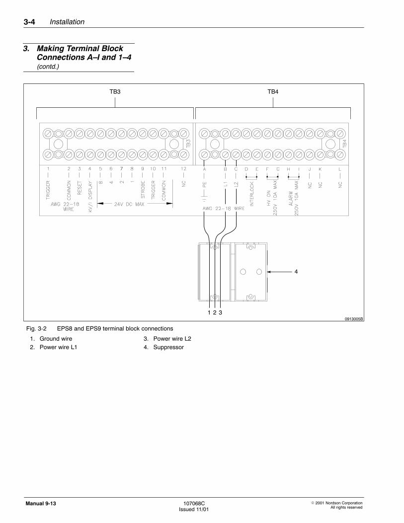
See Figure 3-2 and make the following connections on TB3 and TB4:
1. Remove any packing materials from inside the power supply.
2. Install liquid-tight, one-half-inch conduit at the EPS8 or EPS9 andconnect it using only the Nordson-supplied conduit connector.
3. Install 18–22 gauge wire that meets local electrical codes through theconduit and connect the main power supply leads to terminals A, B,and C on terminal block TB4, as follows:
a. Connect ground wire (1) to TB4-A.b. Connect wire L1 (2) to TB4-B.c. Connect wire L2 (3) to TB4-C.
4. Connect a ground wire (12 gauge or larger) from the ground stud onthe power supply to a true earth ground.
5. Install the wires through the factory-supplied suppressor (4) for thepower wiring (L1, L2, and ground wires):
a. Open the suppressor (4).b. Install wires L1 (2), L2 (3), and ground (1) through the suppressor.c. Tightly close the suppressor, without pinching the wires.
2. Setting the Voltage
3. Making Terminal BlockConnections A–I and 1–4
Installation3-4
� 2001 Nordson CorporationAll rights reserved
107068CIssued 11/01
Manual 9-13
0913005B
TB3 TB4
1 2 3
4
Fig. 3-2 EPS8 and EPS9 terminal block connections
1. Ground wire2. Power wire L1
3. Power wire L24. Suppressor
3. Making Terminal BlockConnections A–I and 1–4(contd.)

Installation 3-5
� 2001 Nordson CorporationAll rights reserved
107068CIssued 11/01
Manual 9-13
6. Make the following optional connections to terminal block TB4, asrequired:
CAUTION: When connecting terminals F, G, H, or I, voltagemust not exceed 250 volts AC and the current must not exceed10 amperes, otherwise, equipment damage can occur.
NOTE: Terminals J, K, and L have no connections (NC).
To: Connect theseterminals:
As follows:
Interrupt power to EPS unit if interlock switchopens
D, E (interlock terminals) 1. Remove factory-installedjumper.
2. Connect customer-suppliedinterlock switch to terminals.
Provide contact closure on a power supplyequipped with a current limiter board, when highvoltage is ON
F, G (high voltage ON) Connect warning device toterminals. See CAUTIONabove.
Provide contact closure on a power supplyequipped with a current limiter board, whencurrent limit is exceeded
H, I (alarm circuit) Connect warning device toterminals. See CAUTIONabove.
NOTE: Do not make the following trigger connections when you use theEPS8 with a manual C-1 hand gun; a switch in that C-1 hand gunprovides the trigger signal.
7. Perform step 7a, 7b, or 7c to make one of the required triggerconnections:
a. To use an air flow switch for contact closure when you actuate thegun, see Figure 3-3 and use the installation instructions thataccompany the air flow switch (1) to install the switch on thepower supply.
� Connect the air flow switch wires to TB3-1 (5) and TB3-2 (4).� Connect the air inlet line (3) to an air pressure source.� Connect the air outlet line (2) to your air spray gun.
b. See Figure 3-2. To use an electromechanical relay for contactclosure when you actuate the gun, connect the relay contacts toTB3-1 and to TB3-2.
c. See Figure 3-2. To use a programmable logic controller (PLC) oranother 24 Vdc source, connect +V to TB3-10 and connect –V toTB3-11. For more information, refer to Using Terminal BlockConnections for PLC Interface in this section.

Installation3-6
� 2001 Nordson CorporationAll rights reserved
107068CIssued 11/01
Manual 9-13
0913006A
1
2
3
45
Fig. 3-3 Air flow switch installed on EPS8
1. Air flow switch2. Air outlet (1/4 -in. NPT)
3. Air inlet (1/4 -in. NPT)4. TB3-2, Common
5. TB3-1, Trigger
3. Making Terminal BlockConnections A–I and 1–4(contd.)
Installation 3-7
� 2001 Nordson CorporationAll rights reserved
107068CIssued 11/01
Manual 9-13
8. If your EPS8 or EPS9 uses an optional current limiter board, seeFigure 3-2 and use TB3-3 to reset the current limiter board by eitherturning the power OFF for at least 10 seconds and then ON again, orby briefly grounding TB3-3.
NOTE: Current limit is factory-set to 100 microamps and is adjustable upto 150 microamps.
9. To remotely select kV or microamps to show on the front paneldisplay, use TB3-4. Set the toggle switch on the front panel to kV.Ground TB3-4 to remotely change the displayed reading from kV tomicroamps.
You can use a digital programmable logic controller (PLC) or other digitaldevice to remotely operate the EPS8 or EPS9 using 12−24 Vdc logic.See Figure 3-2 to make these optional terminal block connections at TB3:
CAUTION: When connecting terminals 5 through 8, do notexceed 24 Vdc maximum, otherwise, equipment damage canoccur.
NOTE: Terminals 5 through 11 are electrically isolated from the rest ofthe circuit.
Terminals 5 through 8 allow you to use a PLC to remotely trigger andadjust the EPS8 or EPS9. These terminals provide the binary patternthat the EPS uses to correctly set the voltage. The following digitalpattern corresponds to the kV settings shown in Table 3-1.
� Terminal 5 = bit 8� Terminal 6 = bit 4� Terminal 7 = bit 2� Terminal 8 = bit 1
4. Using Terminal BlockConnections for PLCInterface

Installation3-8
� 2001 Nordson CorporationAll rights reserved
107068CIssued 11/01
Manual 9-13
Table 3-1 Voltage Settings
Channels EPS9
115 kVmax
EPS8
76 kV max
8 4 2 1 kV kV
0 0 0 0 25 31
0 0 0 1 31 34
0 0 1 0 37 37
0 0 1 1 43 40
0 1 0 0 49 43
0 1 0 1 55 46
0 1 1 0 61 49
0 1 1 1 67 52
1 0 0 0 73 55
1 0 0 1 79 58
1 0 1 0 85 61
1 0 1 1 91 64
1 1 0 0 97 67
1 1 0 1 103 70
1 1 1 0 109 73
1 1 1 1 115 76
NOTE: 1 = 24 Vdc 0 = 0 Vdc
4. Using Terminal BlockConnections for PLCInterface (contd.)

Installation 3-9
� 2001 Nordson CorporationAll rights reserved
107068CIssued 11/01
Manual 9-13
Dip switches 2 and 3 on the main circuit board, SW1-5 (2), allow the PLCto control the power supply. Refer to Table 3-2 and see Figure 3-4.
NOTE: The remaining dip switches on the main circuit board are forfactory settings only.
Table 3-2 Dip Switch Settings
Dip Switch PLC Control Front Panel Control
2 closed (down) open (up)
3 open (up) closed (down)
0913007A
R80R52R82
R65
R76
R58
C12
R78
U7R63
R62
R61
R53
R64
R51
Q3
U11
Q7
U3
R79
U6
C1U2
C23
R71
C22
C21
C19
C24
C20
C9
R7
R15
C3
CR12
R70R72
R68
CR8
R66R67
CR10U5
R73
R14R75R43
C17
CR9R74
Q6
Q1
U10
V1
R12
CR6
C10
C15 C4
C13
C25
U15
R11
R46
CR1
J2
R13
R1
C6C5
C7
R17Q5
R24
R22R10
CR5
54321
R69
C11
CR16
SW1−5
R77
U9
C14
C16
R9
R8
J1 24
CR
2
V2
R34
R32
R36
R37
U12
R33
R38
R81
R29
A11
CR
15
CR
3
U14
R35 R49
R20
R18
CR13
C8C2
C18R19R40CR14
U4
R54
R57R55
R41
2
3
4
5
6
J4
R23
R56 R59
R83
R39
J5
R60 CR7
U13
U8
1
2 13
Fig. 3-4 Main circuit board
1. HV transformer connector (J2) 2. Dip switch panel (SW1-5) 3. Q5 Transistor

Installation3-10
� 2001 Nordson CorporationAll rights reserved
107068CIssued 11/01
Manual 9-13
TB3-9, -10, and -11 provide the controls shown in Table 3-3.
Table 3-3 TB3-9, -10, -11 Connections
Terminal Control
TB3-9, Strobe Enables the EPS8 or EPS9 to read the bitpattern and set the output voltage when thestrobe voltage goes to 24 volts.
TB3-10, Trigger Enables the PLC to trigger the EPS8 or EPS 9using the logic 1 (24 Vdc) signal. Use thisterminal instead of creating a short at TB3-1and TB3-2.
TB3-11, Common Provides a ground terminal for the PLC unit.This terminal connection is independent ofTB3-2 (ground for the EPS) and is a requiredconnection for the digital interface to operatecorrectly.
NOTE: TB3-12 is not connected (NC).
Perform the following steps to install the electrostatic cable:
1. Use the cable cleaning kit to remove any contamination from bothends of the electrostatic cable. Refer to the Parts section for kitordering information.
2. Cut the tip from the vial of high-voltage dielectric oil.
3. See Figure 5-2. Pour the dielectric oil into the high-voltage well of themultiplier.
NOTE: Dielectric oil does not contain PCBs.
4. Slowly install the high-voltage cable into the multiplier well. Wipeaway any oil that overflows the well.
5. Secure the cable with the connecting nut and attach the cable strainrelief onto the side of the power supply cabinet.
6. Refer to the instructions in your gun manual and install the gun end ofthe electrostatic cable to the spray gun. Tighten the connecting nut.
4. Using Terminal BlockConnections for PLCInterface (contd.)
5. Installing theElectrostatic Cable
Installation 3-11
� 2001 Nordson CorporationAll rights reserved
107068CIssued 11/01
Manual 9-13
The electrostatic power supply uses a microammeter for monitoringoutput current. The microammeter is also useful for monitoring theoperating condition of the power supply. To test the microammeter, dothe following:
1. After installing the spray device and cable to the power supply, turnon the power supply using the power ON/OFF switch at the frontpanel. See Figures 2-1 or 2-2.
2. Set the kV/μA switch on the front panel to microamps (μA). SeeFigures 2-1 or 2-2.
3. Trigger the EPS8 or EPS9.
4. Observe the microammeter. If you are far from any grounded object,the microammeter should read approximately 20–80 microamps.
5. Slowly move the gun electrode closer to ground; the microammeterreading increases. The power supply should respond as follows:
a. If you installed the current limiter and adjusted it correctly, youshould be able to almost touch a grounded object before theoutput voltage turns off. The current reading at that point will be100–150 microamps.
b. If you did not install a current limiter in your power supply, theEPS8 or EPS9 will not automatically turn off when the gunelectrode approaches ground.
6. Using the Microammeter

Installation3-12
� 2001 Nordson CorporationAll rights reserved
107068CIssued 11/01
Manual 9-13

� 2001 Nordson CorporationAll rights reserved
107068CIssued 11/01
Manual 9-13
Section 4
Operation

Operation4-0
� 2001 Nordson CorporationAll rights reserved
107068CIssued 11/01
Manual 9-13

Operation 4-1
� 2001 Nordson CorporationAll rights reserved
107068CIssued 11/01
Manual 9-13
Section 4Operation
See Figures 2-1 or 2-2. The following instructions explain the dailyoperation for your power supply.
The following steps describe daily operation of your EPS8 or EPS9.Routine daily maintenance is not required.
1. Place the EPS8 or EPS9 power ON/OFF switch (5) to ON.
2. Set kV to the required setting using the potentiometer (4).
3. If you use an EPS8 (manual spray system), hold the spray gun inyour bare hand to ensure that you are grounded.
4. Pressurize the fluid system.
5. Trigger the gun to begin spraying.
1. Operating the EPS8/9

Operation4-2
� 2001 Nordson CorporationAll rights reserved
107068CIssued 11/01
Manual 9-13

� 2001 Nordson CorporationAll rights reserved
107068CIssued 11/01
Manual 9-13
Section 5
Troubleshooting

Troubleshooting5-0
� 2001 Nordson CorporationAll rights reserved
107068CIssued 11/01
Manual 9-13

Troubleshooting 5-1
� 2001 Nordson CorporationAll rights reserved
107068CIssued 11/01
Manual 9-13
Section 5Troubleshooting
WARNING: Allow only qualified personnel to perform thefollowing tasks. Follow the safety instructions in this documentand all other related documentation.
This section contains troubleshooting procedures. These procedurescover only the most common problems that you may encounter. If youcannot solve the problem with the information given here, contact yourlocal Nordson representative for help.
Problem Page
1. No output voltage at nozzle; loss of wrap with power ON,and kV ON lamp illuminated
5-3
2. Front panel lamps do not illuminate 5-4
3. Power ON lamp illuminated and the kV lamp is not 5-4
4. Power ON and kV lamps illuminated, but kV does not shutoff
5-4
5. Spray device does not power off 5-4
6. All front panel LEDs and lamps extinguished 5-5
7. LEDs and lamps operate correctly, with no kV output, andkV ON lamp is extinguished
5-5
8. LEDs and lamps operate correctly, with no kV output, andkV ON lamp is illuminated
5-6
9. kV indicator remains on even if power supply is nottriggered
5-6
10. kV output weak or erratic 5-6
11. Potentiometer operating incorrectly 5-6
1. Introduction

Troubleshooting5-2
� 2001 Nordson CorporationAll rights reserved
107068CIssued 11/01
Manual 9-13
As you begin to spray, notice the microammeter on the electrostaticpower supply. A normal operating reading is approximately 20–80microamps. Use the operating current as a guide for troubleshooting.For example, if the current reading starts to increase, the flow orconductivity of the coating material might have increased, or moist ordirty air has entered the system. A decrease in the current might indicatethat the power supply voltage has increased, or there is a poor path toground in the system.
WARNING: When checking the power supply with the spraydevice and electrostatic cable removed, see Figure 3-2 andinstall a jumper wire between TB3-1 and TB3-2 to energize thehigh-voltage circuit. After completing the test, remove thejumper.
NOTE: Keep the ball of the kV meter as far away as possible from anygrounded object.
The following table provides troubleshooting procedures for correctingelectrical problems. If multiple causes exist, the table lists thoseproblems in the order of importance.
Troubleshooting ElectricalProblems
Troubleshooting 5-3
� 2001 Nordson CorporationAll rights reserved
107068CIssued 11/01
Manual 9-13
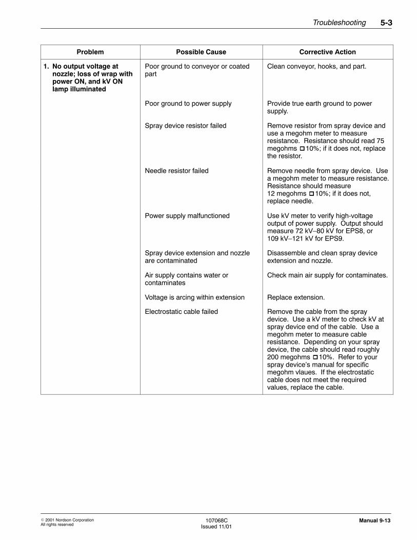
Problem Possible Cause Corrective Action
1. No output voltage atnozzle; loss of wrap withpower ON, and kV ONlamp illuminated
Poor ground to conveyor or coatedpart
Clean conveyor, hooks, and part.
Poor ground to power supply Provide true earth ground to powersupply.
Spray device resistor failed Remove resistor from spray device anduse a megohm meter to measureresistance. Resistance should read 75megohms �10%; if it does not, replacethe resistor.
Needle resistor failed Remove needle from spray device. Usea megohm meter to measure resistance.Resistance should measure12 megohms �10%; if it does not,replace needle.
Power supply malfunctioned Use kV meter to verify high-voltageoutput of power supply. Output shouldmeasure 72 kV–80 kV for EPS8, or109 kV–121 kV for EPS9.
Spray device extension and nozzleare contaminated
Disassemble and clean spray deviceextension and nozzle.
Air supply contains water orcontaminates
Check main air supply for contaminates.
Voltage is arcing within extension Replace extension.
Electrostatic cable failed Remove the cable from the spraydevice. Use a kV meter to check kV atspray device end of the cable. Use amegohm meter to measure cableresistance. Depending on your spraydevice, the cable should read roughly200 megohms �10%. Refer to yourspray device’s manual for specificmegohm vlaues. If the electrostaticcable does not meet the requiredvalues, replace the cable.

Troubleshooting5-4
� 2001 Nordson CorporationAll rights reserved
107068CIssued 11/01
Manual 9-13
Problem Possible Cause Corrective Action
2. Front panel lamps do notilluminate
Output voltage missing or incorrect Verify the following:
1. Energized circuit breaker or fuseahead of power supply.
2. Fuses installed and closed. If a fuseis open, install a new fuse.
3. ON/OFF switch set to ON.
4. Interlock jumper installed on TB4-Dand TB4-E.
3. Power ON lampilluminated and the kVlamp is not
Power supply not triggered Short TB3-1 and TB3-2. If kV lampilluminates, verify contact closure fromtrigger circuit. If kV lamp does notilluminate, replace transistor Q5 on maincircuit board.
Current limiter LED illuminated(current limiter tripped)
Set ON/OFF switch to OFF, and then toON to restore the output voltage. Do thefollowing to adjust the current limiter:
1. Turn the current limiter controlcounter-clockwise.
2. Verify that the spray device electrodeis 0.125 cm (1/8 in.) from a true earthground.
3. Install jumper at TB3-1 and TB3-2 totrigger power supply. Removejumper after testing.
4. Turn the current limiter controlclockwise until red lamp on currentlimiter board illuminates.
4. Power ON and kV lampsilluminated, but kV doesnot shut off
Defective transistor Q5 See Figure 3-4. Replace transistor Q5on main circuit board.
Air flow switch fixed in ON position Verify that air flow switch operatescorrectly.
5. Spray device does notpower off
Trigger switch on spray devicerequires repair
Refer to service manual for spray devicerepair procedures.
Troubleshooting ElectricalProblems (contd)

Troubleshooting 5-5
� 2001 Nordson CorporationAll rights reserved
107068CIssued 11/01
Manual 9-13
Problem Possible Cause Corrective Action
6. All front panel LEDs andlamps extinguished
Incorrect line voltage Verify that ON/OFF switch set to ON.
Verify that fuse at power transformer isnot open. If fuse is open, replace it.
Verify input power at TB4-B and TB4-Cfor correct voltage.
Set 120/240 voltage switch at top oftransformer to correct input voltage.
Calibrate the input voltage. Refer toInput voltage calibration in this section.If the existing input voltage settings donot match the values given in Tables 5-1and 5-2, replace the transformer.
7. LEDs and lamps operatecorrectly, with no kVoutput, and kV ON lampis extinguished
EPS8: Defective trigger switch
PLC signal missing
Defective air flow switch
EPS9: Defective contact closure device
PLC signal missing
Verify trigger circuit as follows:
1. Use length of wire to short TB3-1 andTB3-2.
2. If kV ON lamp illuminates, checktrigger circuit of gun and cable. Referto gun instruction manual.
3. EPS8 only: If kV ON lampilluminates, check fuse for intrinsicsafety barrier inside cabinet. Replacefuse if open.
4. If power supply uses a current limiterboard and kV ON lamp does notilluminate, remove current limiterboard, and then trigger circuit again.If power supply functions correctly,adjust or replace current limiterboard.
5. See Figure 3-4. Replace transistorQ5 on main circuit board, or replacemain circuit board.

Troubleshooting5-6
� 2001 Nordson CorporationAll rights reserved
107068CIssued 11/01
Manual 9-13
Problem Possible Cause Corrective Action
8. LEDs and lamps operatecorrectly, with no kVoutput, and kV ON lampis illuminated
Defective multiplier assembly or maincircuit board
Replace multiplier assembly or maincircuit board.
9. kV indicator remains oneven if power supply isnot triggered
Defective transistor Q5 on maincircuit board
See Figure 3-4. Replace transistor Q5on main circuit board.
10. kV output weak orerratic
Defective or damaged multiplier Replace multiplier.
11. Potentiometeroperating incorrectly
Incorrect dip switch settings Verify correct dip switch settings onmain circuit board.
Damaged ribbon cable connectingdisplay board to main circuit board
Check for damaged ribbon cableconnecting display board to main circuitboard. Replace cable, if damaged.
Incorrectly installed ribbon cable Correctly and firmly seat ribbon cableconnectors.
Incorrectly wired or defectivepotentiometer
Check for damaged potentiometerwiring, or replace potentiometer.
Damaged or defective main circuitboard
Replace main circuit board.
WARNING: Disconnect equipment from line voltage beforeservicing.
Use this procedure to test and calibrate the input voltage.
1. Disconnect and lock out the main power source.
2. Remove the main circuit board (See Figure 2-1, (10) or Figure 2-2,(11)) and turn on the main electrostatic power supply.
3. Connect the electrostatic power supply to a power source followingthese considerations:
� Connect 100/200 Vac units to a 100 Vac source� Connect 120/240 Vac units to a 120 Vac source
4. Set the internal voltage select switch (See Figure 2-1, (9) orFigure 2-2, (9)) to 120.
5. Measure the Vac on TB1-3, TB1-4, and TB1-5 according to thevalues given in Table 5-1.
Troubleshooting ElectricalProblems (contd)
Input Voltage Calibration

Troubleshooting 5-7
� 2001 Nordson CorporationAll rights reserved
107068CIssued 11/01
Manual 9-13
Table 5-1 Terminal Block 1 Voltage Values
Terminal Voltage
3–4 (yellow to red) 18.2 Vac (± 1 V)
3–5 (yellow to red) 18.2 Vac (± 1 V)
4–5 (red to red) 36.4 Vac (± 2 V)
6. Turn off the electrostatic power supply.
7. Set the internal voltage select switch to 240 and turn on theelectrostatic power supply.
8. Measure the AC voltage on TB1-3, TB1-4, and TB1-5 according tothe values given in Table 5-2.
Table 5-2 Terminal Block 1 Voltage Values
Terminal Voltage
3–4 (yellow to red) 9.1 Vac (± 1 V)
3–5 (yellow to red) 9.1 Vac (± 1 V)
4–5 (red to red) 18.2 Vac (± 1 V)
9. Turn off the electrostatic power supply.
10. Disconnect and lock out the main power source and reinstall the maincircuit board.

Troubleshooting5-8
� 2001 Nordson CorporationAll rights reserved
107068CIssued 11/01
Manual 9-13
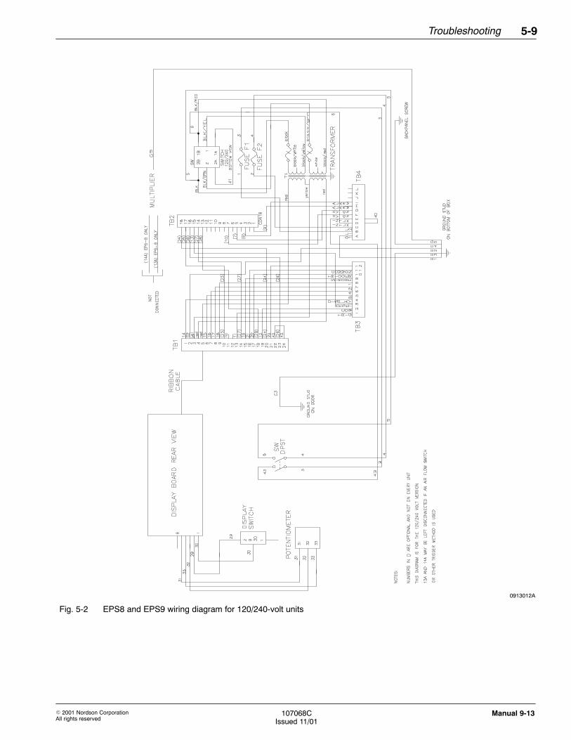
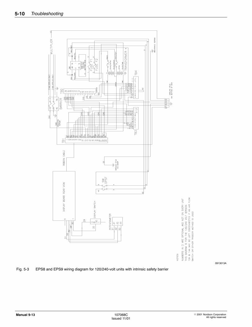
This section contains Figures 5-1 through 5-3, which are the wiringdiagrams for the EPS8 and EPS9 power supplies. Use these diagramsto track disconnected wires during repair and troubleshootingprocedures.
0913011A
Fig. 5-1 EPS8 and EPS9 wiring diagram for 100/200-volt units
2. Wiring Diagrams
Troubleshooting 5-9
� 2001 Nordson CorporationAll rights reserved
107068CIssued 11/01
Manual 9-13
0913012A
Fig. 5-2 EPS8 and EPS9 wiring diagram for 120/240-volt units
Troubleshooting5-10
� 2001 Nordson CorporationAll rights reserved
107068CIssued 11/01
Manual 9-13
0913013A
Fig. 5-3 EPS8 and EPS9 wiring diagram for 120/240-volt units with intrinsic safety barrier

� 2001 Nordson CorporationAll rights reserved
107068CIssued 11/01
Manual 9-13
Section 6
Repair

Repair6-0
� 2001 Nordson CorporationAll rights reserved
107068CIssued 11/01
Manual 9-13

Repair 6-1
� 2001 Nordson CorporationAll rights reserved
107068CIssued 11/01
Manual 9-13
Section 6Repair
WARNING: Allow only qualified personnel to perform thefollowing tasks. Follow the safety instructions in this documentand all other related documentation.
CAUTION: Follow disassembly and assembly steps in order.Performing these steps out of sequence can cause damage tothe power supply, and can void your power supply warranty.
CAUTION: Disassembly of the high-voltage multiplier, maincircuit board, or power transformer will void your power supplywarranty.
During disassembly, repair, or assembly of your power supply, do thefollowing:
� Use the wiring diagrams to keep track of disconnected wires. Referto Wiring Diagrams in the Troubleshooting section of this manual.
� Handle circuit boards correctly and with care.
CAUTION: Do not use solvents of any type to clean internalcomponents of the EPS8 or EPS9, otherwise, equipmentdamage can occur.
� Thoroughly clean and dry all components and cabinet before placingthe power supply into service again.
� When cleaning electrostatic components, such as cable ends or gunextensions, use a Nordson Cable Cleaning Service Kit to clean anddry the components. Refer to the Parts section for kit orderinginformation.
1. Disassembling the PowerSupply

Repair6-2
� 2001 Nordson CorporationAll rights reserved
107068CIssued 11/01
Manual 9-13
Perform the following steps to disassemble the power supply:
1. Place power supply ON/OFF switch to OFF.
2. Disconnect the main power supply and the electrostatic cable.
3. Cover the high-voltage outlet connector and cable end to preventcontamination.
4. See Figure 3-3 and remove the air inlet (3) and outlet (2) lines fromthe air flow switch, if used.
5. See Figure 6-1. Disconnect the ground cable at the ground stud (3).
6. Remove the power supply from the spray area and place on a cleanwork surface for disassembly.
Perform the following steps to remove the multiplier assembly from thepower supply:
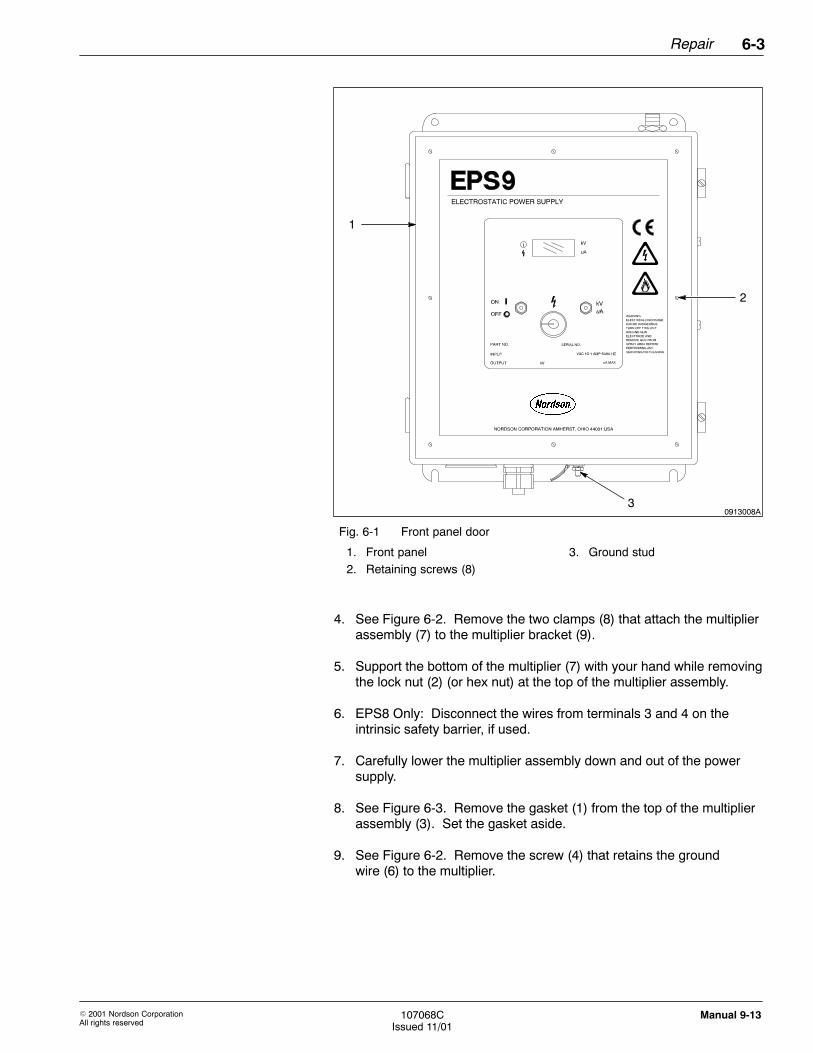
1. See Figure 6-1. Remove the eight screws (2) from the front panel (1),and then open the panel door.
2. See Figure 6-2. Disconnect the high-voltage transformer connectorJ2 (10) from the main circuit board (see also Figure 3-4).
3. EPS8 Only: See Figures 6-1 or 6-2 in the Troubleshooting sectionand disconnect trigger wires 13A and 14A, if installed.
1. Disassembling the PowerSupply (contd.)
2. Removing the MultiplierAssembly
Repair 6-3
� 2001 Nordson CorporationAll rights reserved
107068CIssued 11/01
Manual 9-13
0913008A
1
2
3
Fig. 6-1 Front panel door
1. Front panel2. Retaining screws (8)
3. Ground stud
4. See Figure 6-2. Remove the two clamps (8) that attach the multiplierassembly (7) to the multiplier bracket (9).
5. Support the bottom of the multiplier (7) with your hand while removingthe lock nut (2) (or hex nut) at the top of the multiplier assembly.
6. EPS8 Only: Disconnect the wires from terminals 3 and 4 on theintrinsic safety barrier, if used.
7. Carefully lower the multiplier assembly down and out of the powersupply.
8. See Figure 6-3. Remove the gasket (1) from the top of the multiplierassembly (3). Set the gasket aside.
9. See Figure 6-2. Remove the screw (4) that retains the groundwire (6) to the multiplier.

Repair6-4
� 2001 Nordson CorporationAll rights reserved
107068CIssued 11/01
Manual 9-13
Perform the following steps to install the new multiplier assembly into thepower supply:
NOTE: When the multiplier fails by arc-tracking, the multiplier cable wellbecomes contaminated with a conductive carbon. If this occurs, replacethe multiplier and the high-voltage cable.
1. EPS8 Only: See Figure 6-3. Remove the cable adapter (2) from themultiplier assembly (3), and then install it on the new multiplierassembly.
2. Tighten the cable adapter (2) to 4 N•m (3 ft lb).
3. Use the screw (4) to connect the ground wire (5) to the cableadapter (2) at the top of the multiplier assembly (3).
4. Install the gasket (1) over the end of the cable adapter (2) on the newmultiplier assembly (3).
5. See Figure 6-2. Place the multiplier in the cabinet, and then installthe lock nut (2) (or hex nut) on the cable adapter (1).
6. Position the multiplier firmly against the top of the cabinet, and thentighten the lock nut (2) (or hex nut) to 4 N•m (3 ft lb).
7. Install and tighten the clamps (8) to attach the multiplier assembly (7)to the multiplier bracket (9).
8. Connect the high-voltage transformer connector J2 (10) to the maincircuit board at J2. (See also Figure 3-4.)
9. For an EPS8 with an intrinsic safety barrier, connect the ends of themultiplier wires to terminals 3 and 4 on the barrier.
10. See Figure 6-2. Cut the tip from the vial of high-voltage dielectric oil,and then pour the oil into the high-voltage well (5) of the multiplier.
NOTE: Dielectric oil does not contain PCBs.
3. Installing the MultiplierAssembly

Repair 6-5
� 2001 Nordson CorporationAll rights reserved
107068CIssued 11/01
Manual 9-13
0913014A
1
2
4
3
10
6
9
8
7
5
Fig. 6-2 Multiplier assembly removal
1. Cable adapter2. Lock nut (hex nut)3. Gasket4. Screw
5. High-voltage well6. Ground wire7. Multiplier assembly
8. Clamps9. Bracket
10. High-voltage connector

Repair6-6
� 2001 Nordson CorporationAll rights reserved
107068CIssued 11/01
Manual 9-13
0913015A
1
2
3
4 5
Fig. 6-3 Assembling the multiplier assembly
1. Gasket2. Cable adapter3. Multiplier assembly
4. Screw5. Ground wire
3. Installing the MultiplierAssembly (contd.)

Repair 6-7
� 2001 Nordson CorporationAll rights reserved
107068CIssued 11/01
Manual 9-13
Perform the following steps to assemble the power supply:
1. Install the power supply on the booth or in its normal location.
2. See Figure 6-1. Connect the ground cable at the ground stud (3).
3. See Figure 3-3. Install the air inlet (3) and outlet (2) lines from the airflow switch (1), if used.
4. Remove the cover and plug from the multiplier cable well. Adddielectric oil to the multiplier cable well.
5. Verify that the high-voltage cable is clean and dry before you install it.Use the Nordson Cable Cleaning Service Kit to clean and dry thecable. Refer to the Parts section for kit ordering information.
6. Slowly install the high-voltage cable into the multiplier well. Wipeaway any oil that overflows the well.
7. Secure the electrostatic cable with the connecting nut and attach thecable strain relief onto the side of the power supply cabinet.
8. See Figure 6-1. Close the front panel door and secure the frontpanel (1) with the eight retaining screws (2).
9. Connect the main power supply.
After you replace the display board or main circuit board in the powersupply, use the following steps to test and adjust the display:
1. Place the power supply ON/OFF switch to ON.
2. Turn the potentiometer on the front panel fully clockwise.
3. Verify the following display reading for your power supply:
EPS8 076EPS9 115
4. If the reading is correct, return the potentiometer to its original setting.If the reading is not correct, go to step 5.
NOTE: Do not remove the display board from the power supply doorto perform step 5.
5. Locate R2 on the display board and use a small screwdriver to adjustR2 until the display shows the correct reading.
4. Assembling the PowerSupply
5. Testing the Display

Repair6-8
� 2001 Nordson CorporationAll rights reserved
107068CIssued 11/01
Manual 9-13

� 2001 Nordson CorporationAll rights reserved
107068CIssued 11/01
Manual 9-13
Section 7
Parts

Parts7-0
� 2001 Nordson CorporationAll rights reserved
107068CIssued 11/01
Manual 9-13

Parts 7-1
� 2001 Nordson CorporationAll rights reserved
107068CIssued 11/01
Manual 9-13
Section 7Parts
To order parts, call the Nordson Customer Service Center or your localNordson representative. Use this five-column parts list, and theaccompanying illustration, to describe and locate parts correctly.
Numbers in the Item column correspond to numbers that identify parts inillustrations following each parts list. The code NS (not shown) indicatesthat a listed part is not illustrated. A dash (—) is used when the partnumber applies to all parts in the illustration.
The number in the Part column is the Nordson Corporation part number.A series of dashes in this column (- - - - - -) means the part cannot beordered separately.
The Description column gives the part name, as well as its dimensionsand other characteristics when appropriate. Indentions show therelationships between assemblies, subassemblies, and parts.
Item Part Description Quantity Note
— 000000 Assembly 1
1 000 000 � Subassembly 2 A
2 000 000 � � Part 1
� If you order the assembly, items 1 and 2 will be included.� If you order item 1, item 2 will be included.� If you order item 2, you will receive item 2 only.
The number in the Quantity column is the quantity required per unit,assembly, or subassembly. The code AR (As Required) is used if thepart number is a bulk item ordered in quantities or if the quantity perassembly depends on the product version or model.
Letters in the Note column refer to notes at the end of each parts list.Notes contain important information about usage and ordering. Specialattention should be given to notes.
1. Introduction
Using the Illustrated PartsList

Parts7-2
� 2001 Nordson CorporationAll rights reserved
107068CIssued 11/01
Manual 9-13
See Figure 7-1.
Item Part Description Quantity Note
— 229912 Power Supply, EPS8, with current limiter 1
— 229914 Power Supply, EPS8 1
— 184250 Power Supply, EPS8, with intrinsic safety barrier, C-1 1
— 229913 Power Supply, EPS8, with current limiter, 100/200 Vac 1
1 184261 � Boot, toggle switch 2
NS 248741 � Seal, shaft rotary 1
NS 184276 � Fuse, repl. barrier 1
2 184251 � Board, current limiter 1
3 106381 � Multiplier, HV 1
4 184258 � Tag, warning 1
NS 184289 � Switch, toggle, ON/OFF 1
5 184287 � Wire group, display 1
NS 184259 � Switch, toggle, kV/μA 1
6 184252 � Board, display 1
7 184273 � Panel, sub-assembly, 120/240 Vac 1
7 184253 � Panel, sub-assembly, 100/200 Vac 1 A
8 248704 � � Fuse, fast, 0.75-amp 2
9 933161 � � Fuseholder, fuse 2
10 184264 � � Transformer, power 1 A
11 184265 � � Switch, voltage select 1
12 933645 � � Block, terminal, 12 poles 1
13 184267 � Barrier, intrinsic safety 1
14 184274 � Guide, card 1 B
14 243542 � Guide, card (for current limiter units only) 1 B
15 184277 � Rod, threaded 2 B
15 246325 � Rod, threaded (for current limiter units only) 2 B
NOTE A: This sub-assembly is for use with EPS8, part 229913, only.
B: EPS units with current limiter use both card guides and both threaded rods (items 14 and 15).
NS: Not Shown
Continued on next page
EPS8 Standard Parts

Parts 7-3
� 2001 Nordson CorporationAll rights reserved
107068CIssued 11/01
Manual 9-13
Item Part Description Quantity Note
16 184282 � Seal, oil-tight 1
17 184284 � Cable assembly, ribbon 1
NS 184285 � Spacer, switch 1
NS 184286 � Ring, locking 2
18 211274 � Gasket, 1.51 ID 1
NS 223706 � Wire group, barrier, safety 1
19 185068 � Suppressor, round cable, large 1
20 185067 � Suppressor, round cable, small 4
21 184248 � Board, circuit main 1
22 247624 � � Transistor, Q5 1
23 229905 � Adapter, multiplier/cable, EPS 1
23 229926 � Adapter, multiplier/cable, EPS (intrinsic safetybarrier unit only)
1
24 982623 � Screw, pan head, S/seal, 10-24 x 0.375, steel, zinc 2
25 982721 � Screw, pan head, S/seal, 6-32 x 0.625, steel, zinc 8
26 981020 � Screw, pan head, 6-32 x 0.250, steel, zinc 3, 1 C
27 982959 � Screw, flat head, 2-56 x 0.190, stainless steel 2
NS 229933 � Kit, ship with, EPS 1
NS 229903 � � Tag, warning, hazardous, inserts 1
NS 229904 � � Tag, warning, dual-volt, inserts 1
NS 184246 � Plate, suppressor 1
28 240674 � Tag, ground 2
29 240976 � Clamp, ground 1
30 242867 � Tag, warning 1
NOTE C: EPS units with current limiter use 3 screws; units without current limiter use 1 screw (item 26).
NS: Not Shown
Continued on next page

Parts7-4
� 2001 Nordson CorporationAll rights reserved
107068CIssued 11/01
Manual 9-13
Item Part Description Quantity Note
31 246164 � Bracket, multiplier 1
NS 248694 � Knob, collet 1
NS 248695 � Cap, flat 1
32 151444 � Suppressor, flat 1
33 970970 � Clamp, hose, #52 2
34 937189 � Potentiometer 1
35 296038 � Spacer 4
36 140475 � Tag, warning 1
37 981149 � Screw, round head, 10-32 x 0.375, steel, zinc 4
NS 984121 � Nut, hex mach, #10-24, steel, zinc 2
38 805074 � Connector, straight, liquid-tight 1
39 983524 � Washer, lock, #6 1
40 970972 � Clamp, cable 1
41 983003 � Washer, flat 4
42 982966 � Retainer, captive screw 8
43 242837 � Mount, cable strap 2
44 939004 � Strap, cable 2
45 180119 � Lock nut 1
NS: Not Shown
EPS8 Standard Parts (contd)

Parts 7-5
� 2001 Nordson CorporationAll rights reserved
107068CIssued 11/01
Manual 9-13
0913009A
1
3541 17
40194344
5
2542
A B B
View A−A View B−B
21
22
14
15
2
14
15
3836
2043
20
45
18
3
33
31
8
12
13
16
23
26
44 26
10
20
A
7
39 37
24
9
2829
4
6 27 32
34
30
11
Fig. 7-1 EPS8 standard parts

Parts7-6
� 2001 Nordson CorporationAll rights reserved
107068CIssued 11/01
Manual 9-13
See Figure 7-2.
Item Part Description Quantity Note
— 184260 Power Supply, EPS9, with current limiter 1
— 229915 Power Supply, EPS9, with current limiter, 100/200 Vac 1
1 184261 � Boot, toggle switch 2
NS 248741 � Seal, shaft rotary 1
2 184251 � Board, current limiter 1
3 106324 � Multiplier, HV 1
4 184249 � Board, circuit main 1
5 247624 � � Transistor, Q5 1
NS 184289 � Switch, toggle, ON/OFF 1
6 184287 � Wire group, display 1
NS 184259 � Switch, toggle, kV/μA 1
7 184252 � Board, display 1
8 184253 � Panel, sub-assembly, 100/200 Vac 1 A
8 184273 � Panel, sub-assembly, 120/240 Vac 1
9 248704 � � Fuse, 0.75-amp 2
10 933161 � � Fuseholder, fuse 2
11 184264 � � Transformer, power 1 A
12 933645 � � Block, terminal, 12 poles 1
13 184258 � Tag, warning 1
14 984705 � Nut, hex 1
15 184274 � Guide, card 1 B
15 243542 � Guide, card (for units with current limiter only) 1 B
16 184277 � Rod, threaded 1 B
16 246325 � Rod, threaded (for units with current limiter only) 1 B
NOTE A: This sub-assembly is for use with EPS9, part 229915, only.
B: EPS units with current limiter use both card guides and both threaded rods (items 15 and 16).
NS: Not Shown
Continued on next page
EPS9 Standard Parts

Parts 7-7
� 2001 Nordson CorporationAll rights reserved
107068CIssued 11/01
Manual 9-13
Item Part Description Quantity Note
17 184265 � Switch, voltage select 1
18 184284 � Cable assembly, ribbon 1
NS 184285 � Spacer, switch 1
NS 184286 � Ring, locking 2
19 955046 � Gasket 1
20 185068 � Suppressor, round cable, large 1
21 185067 � Suppressor, round cable, small 4
22 982623 � Screw, pan head, S/seal, 10-24 x 0.375, steel, zinc 2
23 982721 � Screw, pan head, S/seal, 6-32 x 0.500, steel, zinc 8
24 981020 � Screw, pan head, 6-32 x 0.250, steel, zinc 3, 1 C
25 982959 � Screw, flat head, 2-56 x 0.190, stainless steel 2
NS 229933 � Kit, ship with, EPS 1
NS 229903 � � Tag, warning, hazardous, inserts 1
NS 229904 � � Tag, warning, dual-volt, inserts 1
NS 184246 � Plate, suppresser 1
26 240674 � Tag, ground 2
27 240976 � Clamp, ground 1
28 242867 � Tag, warning 1
29 246164 � Bracket, multiplier 1
NS 248694 � Knob, collet 1
NS 248695 � Cap, flat 1
30 151444 � Suppresser, flat 1
NOTE C: EPS units with current limiter use 3 screws; units without current limiter use 1 screw (item 24).
NS: Not Shown
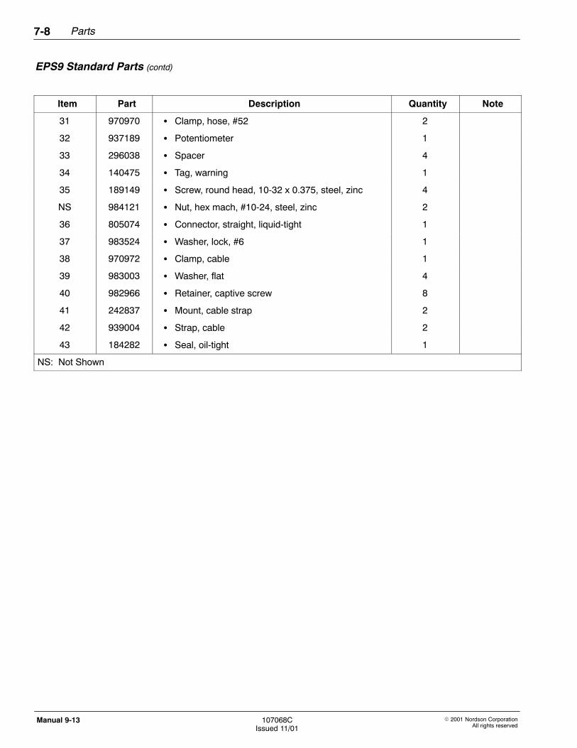
Parts7-8
� 2001 Nordson CorporationAll rights reserved
107068CIssued 11/01
Manual 9-13
Item Part Description Quantity Note
31 970970 � Clamp, hose, #52 2
32 937189 � Potentiometer 1
33 296038 � Spacer 4
34 140475 � Tag, warning 1
35 189149 � Screw, round head, 10-32 x 0.375, steel, zinc 4
NS 984121 � Nut, hex mach, #10-24, steel, zinc 2
36 805074 � Connector, straight, liquid-tight 1
37 983524 � Washer, lock, #6 1
38 970972 � Clamp, cable 1
39 983003 � Washer, flat 4
40 982966 � Retainer, captive screw 8
41 242837 � Mount, cable strap 2
42 939004 � Strap, cable 2
43 184282 � Seal, oil-tight 1
NS: Not Shown
EPS9 Standard Parts (contd)
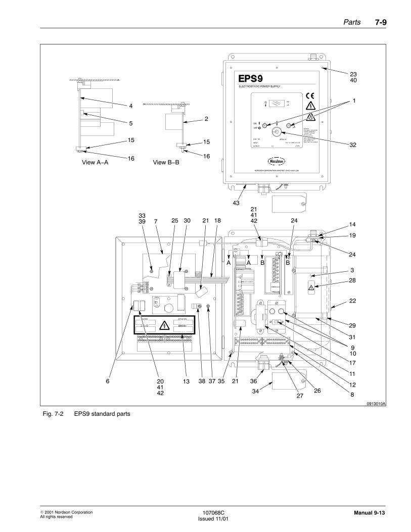
Parts 7-9
� 2001 Nordson CorporationAll rights reserved
107068CIssued 11/01
Manual 9-13
0913010A
1
3339 7 18
3813204142
6
A B B
View A−A View B−B
4
5
15
16
2
15
16
36
34
2141
21
14
19
3
28
22
31
29
9
12
24
42 24
11
25 30 21
A
8
2340
37 35
10
32
2627
17
43
Fig. 7-2 EPS9 standard parts
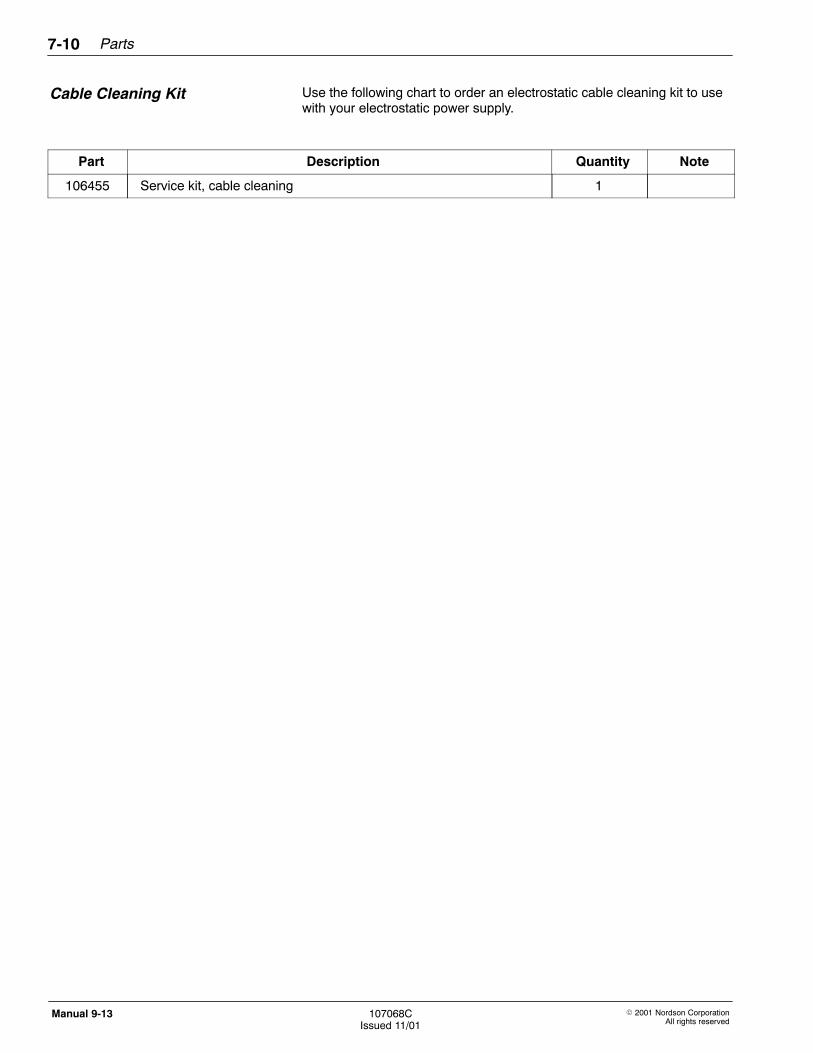
Parts7-10
� 2001 Nordson CorporationAll rights reserved
107068CIssued 11/01
Manual 9-13
Use the following chart to order an electrostatic cable cleaning kit to usewith your electrostatic power supply.
Part Description Quantity Note
106455 Service kit, cable cleaning 1
Cable Cleaning Kit