Embed Size (px)
Citation preview
EPR SpectrometerUser�s Manual
Advanced Operations
E 500

Advanced Operations
Authors: Dr. JinJie Jiang, Dr. Ralph T. WeberIllustrations: Aaron A. Heiss, Dr. Ralph T. Weber, Dr. JinJie JiangEPR DivisionBruker BioSpin CorporationBillerica, MA USA
Software Version 2.1Manual Version 1.0
May, 2000Part Number 8637065
ELEXSYS E 500 User�s Manual: Advanced OperationsManual Version 1.0Software Version 2.1
Copyright © 2001 Bruker BioSpin Corporation
The text, figures, and programs have been worked out with the utmost care. However, we cannot accept either legal responsibility or any liability for any incorrect statements which may remain, and their consequences. The following publication is protected by copyright. All rights reserved. No part of this publication may be reproduced in any form by photocopy, microfilm or other proce-dures or transmitted in a usable language for machines, in particular data processing systems with-out our written authorization. The rights of reproduction through lectures, radio and television are also reserved. The software and hardware descriptions referred in this manual are in many cases registered trademarks and as such are subject to legal requirements.
This manual is part of the original documentation for the Bruker ELEXSYS spectrometer.

Preface 0Bruker strives to supply you with instructional and accurate doc-umentation. We encourage you to tell us how we are doing.Please send us your suggestions for improvements, corrections,or bug reports. If there is anything you particularly liked, tell usas well. With your input and assistance, Bruker can continuallyimprove its products and documentation.
You can send your messages and correspondence via e-mail,FAX, telephone, or mail. It is important to include the documentname, product name, version number, and page number in yourresponse. Here are the addresses and numbers to which you cansend your messages.
e-mail: [email protected]
FAX: 978-670-8851
Tel. 978-663-7406
mailingaddress
EPR DivisionBruker BioSpin Corporation19 Fortune DriveManning ParkBillerica, MA 01821 USA
Thank you for your help.
Elexsys E 500 User�s Manual: Advanced Operations

Electrical Safety
Electrical Safety 0.1Do not remove any of the protective covers or panels of theinstrument. They are fitted to protect you and should be openedby qualified service personnel only.
Power off the instrument and disconnect the line cord beforestarting any cleaning work in the spectrometer. Never operatethe instrument with the grounding cord disconnected or bypassed. Facility wiring must include a properly grounded powerreceptacle.
Chemical Safety 0.2Individuals working with hazardous chemicals, toxic substances,or enclosed liquid samples must take every precaution possibleto avoid exposure to these agents. As a general rule, THINK OFTHE CHEMICAL LABORATORY AS A HAZARDOUSENVIRONMENT IN WHICH YOU MUST CONTINUALLYMAINTAIN A HIGH STANDARD OF VIGILANCE. Do notassume a cavalier attitude -- the substances with which you workpresent very real, and very serious threats to your health andsafety.
Adhere to all currently recommended guidelines for standardlaboratory safety as promulgated by governmental codes andcontemporary laboratory practice. Inform yourself about thespecific risks that are present when you handle actual or poten-tial carcinogens (cancer-causing agents), explosive materials,strong acids, or any liquids that are sealed in glass containers.
iv

Chemical Safety
Specifically:
� Be extremely careful when you handle sealed glass samplesthat are rapidly heated or cooled. The rapid cooling of somesamples may result in the formation of a solid bolus in thesample tube that may make the tube prone to explosive rup-ture.
� Educate yourself about the temperature at which chemicalsevaporate. When a sample gets close to the temperature atwhich it evaporates, it may quickly become volatile.
� In general, the safety threat posed by flying glass and vio-lently escaping gases and liquids should not be underesti-mated.
� Wear safety glasses, face masks, and other protective cloth-ing whenever there is any risk of spillage, breakage, or explo-sion. Protective shields should also be employed when thereis any risk of explosion.
� Be sure that both storage and working areas are properly ven-tilated. They should be equipped with powerful blowers andfume heads.
� Store chemicals safely. Avoid integrating containers of chem-icals that may result in dangerous combinations.
� Practice good housekeeping in work and storage areas. Cleanup spills and refuse promptly. Do not leave volatile, combus-tible, or acidic liquids exposed on counters, benches, or otherwork areas.
� Make certain all chemical containers are properly labeled andclassified, and that especially hazardous materials are appro-priately designated with clearly understood decals or warn-ings.
� Never taste or inhale unmarked chemicals.
Elexsys E 500 User�s Manual: Advanced Operations v

Microwave Safety
� All laboratories should be equipped with fire doors, fireextinguishers, fire smothering materials, and sprinkler sys-tems or showers, as well as a detailed fire safety plan.
Microwave Safety 0.3
As long as the microwaves are contained in metal structures,microwaves can be very safe. Here are some precautions which,if followed, will eliminate the possibility of injury due to themicrowaves.
� Do not have an open waveguide when the microwave poweris on.
� Switch the bridge to standby when you remove or changeEPR cavities.
� Never look down an open waveguide when there is micro-wave power. The eyes are very susceptible to damage frommicrowaves.
vi
Table of Contents
Table of Contents 0.4
0 Preface ................................................................................. iii0.1 Electrical Safety.......................................................................................... iv0.2 Chemical Safety.......................................................................................... iv0.3 Microwave Safety....................................................................................... vi0.4 Table of Contents ...................................................................................... vii
1 Introduction ........................................................................1-11.1 How to Find Things.................................................................................. 1-11.2 Typographical Conventions...................................................................... 1-4
1.2.1 Fonts .............................................................................................................1-41.2.2 Special notes.................................................................................................1-4
2 EPR Spectrometer Calibration ...........................................2-12.1 Standard Samples ..................................................................................... 2-2
2.1.1 DPPH (a, a� - diphenyl-ß-picryl hydrazyl)...................................................2-22.1.2 Weak and Strong Pitch Samples ..................................................................2-3
2.2 Theory of Signal Channel Calibration...................................................... 2-42.2.1 Introduction ..................................................................................................2-42.2.2 Amplitude Calibration..................................................................................2-52.2.3 Phase Calibration .........................................................................................2-7
2.3 Calibrating the Signal Channel................................................................. 2-9
3 System Performance Tests ................................................3-13.1 Signal to Noise Ratio Test ........................................................................ 3-2
3.1.1 Preparing for the S/N Test............................................................................3-4
Elexsys E 500 User�s Manual: Advanced Operations vii
Table of Contents
3.1.2 Acquire the Signal Spectrum........................................................................3-63.1.3 Acquire the Noise Spectrum.......................................................................3-133.1.4 Measuring the Signal to Noise Ratio..........................................................3-223.1.5 Signal to Noise Ratio Test for an ER 4102ST Cavity ................................3-28
4 Spectrometer Configuration .............................................. 4-14.1 The Field Folder........................................................................................4-1
4.1.1 ER032T Field Controller..............................................................................4-24.1.2 FF-Lock ........................................................................................................4-24.1.3 Teslameter (Gaussmeter)..............................................................................4-34.1.4 Rapid Scan....................................................................................................4-4
4.2 The Misc. Folder .......................................................................................4-54.2.1 Microwave Band ..........................................................................................4-54.2.2 Microwave Frequency Counter ....................................................................4-64.2.3 Temperature Controller ................................................................................4-84.2.4 Transient Recorder ......................................................................................4-9
4.3 The Signal Channel Folder .....................................................................4-104.3.1 Calibration Options ....................................................................................4-114.3.2 Standard Calibration Data ..........................................................................4-114.3.3 RF Calibration Data....................................................................................4-11
4.4 Other Folders ..........................................................................................4-11
5 Field Offset & g-Factor ...................................................... 5-15.1 Field Calibration Standards.......................................................................5-15.2 Measuring the Field Offset .......................................................................5-2
5.2.1 Calibrating the Field Offset ..........................................................................5-25.2.2 Tips for Measuring the Field Offset .............................................................5-8
5.3 g-Value Measurements .............................................................................5-9
viii

Table of Contents
6 The Fast Digitizer & Rapid Scans ......................................6-16.1 Rapid Time Scan Experiments ................................................................. 6-1
6.1.1 The Fast Digitizer.........................................................................................6-16.1.2 Performing a Rapid Time Scan Experiment ................................................6-26.1.3 Fast Digitizer Parameters .............................................................................6-5
6.2 The Rapid Field Scan Experiment............................................................ 6-76.2.1 Configuring the Rapid Scan Experiment .....................................................6-86.2.2 Defining a Rapid Scan Experiment..............................................................6-96.2.3 Rapid Scan Parameters...............................................................................6-13
6.3 2D Experiment with Rapid Scan ............................................................ 6-166.4 Field Sweep Calibration ......................................................................... 6-18
7 Nonlinear Sweeps ..............................................................7-17.1 Nonlinear Field Sweeps............................................................................ 7-2
7.1.1 Performing Nonlinear Field Sweeps ............................................................7-37.1.2 Comparison of the Results ...........................................................................7-7
7.2 Nonlinear Scans in a 2D Experiment ....................................................... 7-9
8 Macros ...............................................................................8-18.1 Recording a Macro ................................................................................... 8-28.2 Making a Macro User Button ................................................................... 8-78.3 Writing a Macro with a Text Editor ....................................................... 8-10
8.3.1 Special Macro Commands ......................................................................... 8-108.3.2 The Macro Body ........................................................................................8-158.3.3 A Macro Example ...................................................................................... 8-15
9 Automatic Post-Processing ................................................9-19.1 Activating Auto Post-Processing.............................................................. 9-2
Elexsys E 500 User�s Manual: Advanced Operations ix

Table of Contents
9.2 Multiple Auto Post-Processing Routines ..................................................9-89.2.1 Setting Up More than Three Commands......................................................9-8
10 Implementing Help ........................................................ 10-110.1 Writing a Help File ...............................................................................10-1
10.1.1 Help File Format.......................................................................................10-110.1.2 Help Filenames.........................................................................................10-310.1.3 Where to Put the Help Files......................................................................10-3
10.2 Accessing Help .....................................................................................10-4
11 Changing Microwave Bridges ........................................ 11-111.1 Removing the Microwave Bridge .........................................................11-111.2 Installing a Microwave Bridge..............................................................11-4
12 Installing & Using Accessories ...................................... 12-112.1 Frequency Counters ..............................................................................12-2
12.1.1 The MBC Board .......................................................................................12-212.1.2 The Bruker Frequency Counter ................................................................12-412.1.3 Frequency Counters by Other Vendors ....................................................12-4
12.2 ER 41X1VT Variable Temperature Systems........................................12-612.3 ER 4112HV Variable Temperature Systems ......................................12-10
12.3.1 Setting the Controller Up........................................................................12-1012.3.2 The Temperature Folder .........................................................................12-1212.3.3 The ITC5 Control Folder........................................................................12-14
12.4 The E 033M Field Frequency Lock ....................................................12-1712.4.1 Installing an FF-Lock .............................................................................12-1812.4.2 Using the FF-Lock in Lock-in Mode......................................................12-2112.4.3 Troubleshooting Locking Problems .......................................................12-2412.4.4 Marker ode..............................................................................................12-26
x
Table of Contents
12.4.5 Out of Locking Range Errors ................................................................. 12-3012.5 The E 035M Teslameter ..................................................................... 12-31
12.5.1 Installing a Teslameter ........................................................................... 12-3112.5.2 Using the Teslameter.............................................................................. 12-3312.5.3 The Standard Control Folder.................................................................. 12-3512.5.4 The Optional Control Folder .................................................................. 12-3612.5.5 Calibrating the Field Offset....................................................................12-3712.5.6 Troubleshooting ..................................................................................... 12-38
12.6 The ER 218PG1 Goniometer.............................................................. 12-3912.6.1 Installing a Programmable Goniometer ................................................. 12-3912.6.2 Configuring the Goniometer .................................................................. 12-40
13 Wiring and Configuration ................................................13-113.1 Console Module Arrangement ............................................................. 13-113.2 Connectors and Indicators in a Nutshell............................................... 13-2
13.2.1 SCT Connectors ....................................................................................... 13-213.2.2 SCT LED Indicators................................................................................. 13-413.2.3 HCPU Hall Field Controller LED Indicators...........................................13-513.2.4 Transputer Connectors ............................................................................. 13-6
13.3 SCT-PS ................................................................................................. 13-813.3.1 SCT-PS Connectors ................................................................................. 13-813.3.2 SCT-PS Indicators.................................................................................... 13-9
13.4 SCT..................................................................................................... 13-1013.4.1 SCT Connectors ..................................................................................... 13-1013.4.2 SCT Indicators ....................................................................................... 13-12
13.5 Modulation Amplifier......................................................................... 13-1313.5.1 Modulation Amplifier Connectors ......................................................... 13-13
13.6 HCPU ................................................................................................. 13-1513.6.1 HCPU Indicators .................................................................................... 13-1513.6.2 HCPU Connectors.................................................................................. 13-15
Elexsys E 500 User�s Manual: Advanced Operations xi
Table of Contents
13.7 ADF.....................................................................................................13-1713.7.1 ADF Indicators .......................................................................................13-1713.7.2 ADF Connectors .....................................................................................13-18
13.8 RSC.....................................................................................................13-2113.8.1 RSC Indicators........................................................................................13-2113.8.2 RSC Connectors .....................................................................................13-21
14 Experiment Setup .......................................................... 14-114.1 Standard Experiments ...........................................................................14-2
14.1.1 Field or Time Sweeps with the Signal Channel .......................................14-214.1.2 Field or Time Sweeps with the Fast Digitizer (ADF) ..............................14-314.1.3 Rapid Field Scans with the Fast Digitizer (ADF) ....................................14-4
14.2 Custom Experiments .............................................................................14-514.2.1 Quadrature Detection................................................................................14-514.2.2 Externally Triggered Sweeps with the Signal Channel ..........................14-1314.2.3 Externally Triggered Sweeps with the ADF ..........................................14-1514.2.4 Externally Triggered Rapid Field Sweeps..............................................14-1714.2.5 External Field Modulation......................................................................14-1914.2.6 Other Forms of Modulation....................................................................14-2114.2.7 Sweeps with Double Modulation ...........................................................14-2414.2.8 Triggered Quadrature Detection with the ADF......................................14-3014.2.9 Transient Quadrature Signal Capture with the ADF ..............................14-3214.2.10 Externally Controlled Field Sweep with the ADF ...............................14-33
15 Xepr Under SGI IRIX ..................................................... 15-115.1 General Information..............................................................................15-115.2 Network Settings...................................................................................15-2
15.2.1 ec0 and ec1 ...............................................................................................15-215.2.2 NFS (Network File System) .....................................................................15-215.2.3 UNS (Unified Name Service)...................................................................15-215.2.4 Routing .....................................................................................................15-3
xii
Table of Contents
15.3 UNIX Workstation Configuration ........................................................ 15-415.3.1 Flags ......................................................................................................... 15-415.3.2 Swap Space .............................................................................................. 15-615.3.3 Security .................................................................................................... 15-6
15.4 Reinstalling or Upgrading Xepr ........................................................... 15-715.4.1 List of Important Files.............................................................................. 15-715.4.2 Performing an Installation or Upgrade..................................................... 15-8
15.5 Initial Setup of Xepr ............................................................................. 15-915.5.1 Setting Up Xepr for Your Account .......................................................... 15-915.5.2 Setting Up the Properties of the Xepr Software..................................... 15-11
15.6 How to Start and Stop Xepr................................................................ 15-1615.6.1 Starting Xepr from a UNIX shell ...........................................................15-16
15.7 Aborting Xepr..................................................................................... 15-1815.7.1 Logout from the Current Account.......................................................... 15-1815.7.2 The Ctrl-C command.............................................................................. 15-1815.7.3 The Kill Command................................................................................. 15-19
15.8 The Xepr Printer ................................................................................. 15-2015.8.1 Reinstalling the Xepr Printer.................................................................. 15-2015.8.2 Printing a Spectrum to a File.................................................................. 15-2315.8.3 When Printing Goes Wrong ................................................................... 15-25
15.9 Networking & Remote Operation ...................................................... 15-2715.9.1 Remote Access to Xepr.......................................................................... 15-2715.9.2 Remote Logon to the EPR Server .......................................................... 15-2815.9.3 Remote Control of the Spectrometer...................................................... 15-2915.9.4 Data Transfer Via the Network .............................................................. 15-29
16 Xepr Under Linux ...........................................................16-116.1 General Information ............................................................................. 16-116.2 Network Settings .................................................................................. 16-3
Elexsys E 500 User�s Manual: Advanced Operations xiii
Table of Contents
16.2.1 eth0 and eth1.............................................................................................16-316.2.2 NFS (Network File System) .....................................................................16-316.2.3 Name Server .............................................................................................16-316.2.4 Routing .....................................................................................................16-6
16.3 Linux Workstation Service Configuration............................................16-716.3.1 Flags .........................................................................................................16-716.3.2 Swap Space.............................................................................................16-1116.3.3 Security...................................................................................................16-11
16.4 Reinstalling or Upgrading Xepr..........................................................16-1316.4.1 List of Important Files ............................................................................16-1316.4.2 Performing an Installation or Upgrade ...................................................16-14
16.5 Initial Setup of Xepr............................................................................16-1516.5.1 Creating a New User Account ................................................................16-1516.5.2 Setting Up Xepr for a New Account ......................................................16-1616.5.3 Setting Up the Properties of the Xepr Software .....................................16-19
16.6 How to Start and Stop Xepr ................................................................16-2416.6.1 Starting Xepr from a UNIX shell ...........................................................16-24
16.7 Aborting Xepr .....................................................................................16-2616.7.1 Logout from the Current Account. .........................................................16-2616.7.2 The Ctrl-C command..............................................................................16-2616.7.3 The Kill Command .................................................................................16-27
16.8 The Xepr Printer .................................................................................16-2816.8.1 Installing a Printer ..................................................................................16-2816.8.2 Printing a Spectrum to a File ..................................................................16-3516.8.3 Print Preview ..........................................................................................16-3716.8.4 When Printing Goes Wrong ...................................................................16-38
16.9 Networking & Remote Operation .......................................................16-4016.9.1 Remote Access to Xepr ..........................................................................16-4016.9.2 Remote Logon to the EPR Server ..........................................................16-4116.9.3 Remote Control of the Spectrometer ......................................................16-4216.9.4 Data Transfer Via the Network ..............................................................16-42
xiv
Table of Contents
17 Acquisition Server Diagnostics .......................................17-117.1 What Is Normal?................................................................................... 17-2
17.1.1 Connections.............................................................................................. 17-217.1.2 A Normal Booting Process....................................................................... 17-4
17.2 Trouble Shooting .................................................................................. 17-617.2.1 ACPU Diagnostics ................................................................................... 17-717.2.2 Transputer Diagnostics........................................................................... 17-16
Index .......................................................................................I-1
Elexsys E 500 User�s Manual: Advanced Operations xv

Notes
xvi
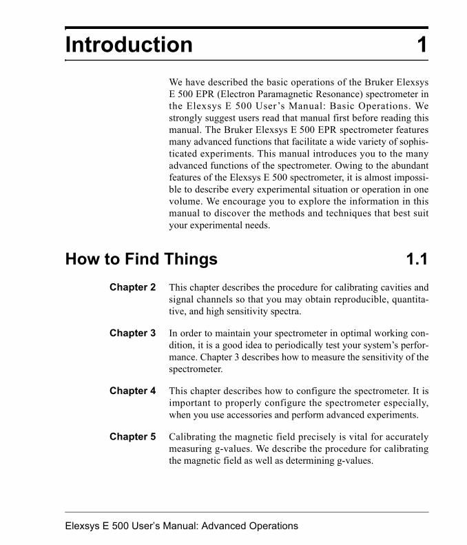
Introduction 1We have described the basic operations of the Bruker ElexsysE 500 EPR (Electron Paramagnetic Resonance) spectrometer inthe Elexsys E 500 User�s Manual: Basic Operations. Westrongly suggest users read that manual first before reading thismanual. The Bruker Elexsys E 500 EPR spectrometer featuresmany advanced functions that facilitate a wide variety of sophis-ticated experiments. This manual introduces you to the manyadvanced functions of the spectrometer. Owing to the abundantfeatures of the Elexsys E 500 spectrometer, it is almost impossi-ble to describe every experimental situation or operation in onevolume. We encourage you to explore the information in thismanual to discover the methods and techniques that best suityour experimental needs.
How to Find Things 1.1Chapter 2 This chapter describes the procedure for calibrating cavities and
signal channels so that you may obtain reproducible, quantita-tive, and high sensitivity spectra.
Chapter 3 In order to maintain your spectrometer in optimal working con-dition, it is a good idea to periodically test your system�s perfor-mance. Chapter 3 describes how to measure the sensitivity of thespectrometer.
Chapter 4 This chapter describes how to configure the spectrometer. It isimportant to properly configure the spectrometer especially,when you use accessories and perform advanced experiments.
Chapter 5 Calibrating the magnetic field precisely is vital for accuratelymeasuring g-values. We describe the procedure for calibratingthe magnetic field as well as determining g-values.
Elexsys E 500 User�s Manual: Advanced Operations
How to Find Things
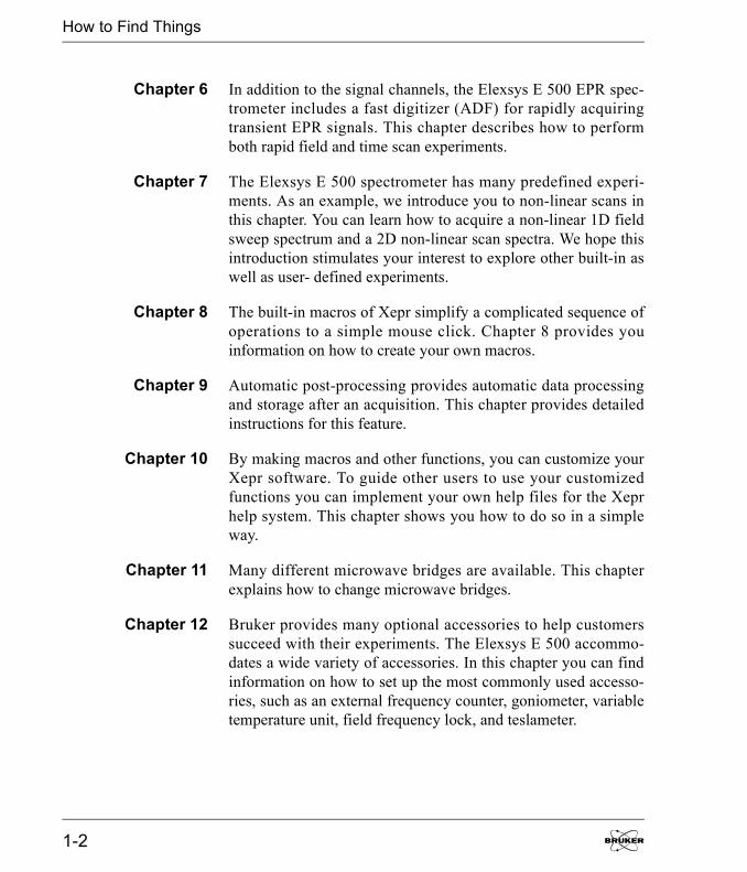
Chapter 6 In addition to the signal channels, the Elexsys E 500 EPR spec-trometer includes a fast digitizer (ADF) for rapidly acquiringtransient EPR signals. This chapter describes how to performboth rapid field and time scan experiments.
Chapter 7 The Elexsys E 500 spectrometer has many predefined experi-ments. As an example, we introduce you to non-linear scans inthis chapter. You can learn how to acquire a non-linear 1D fieldsweep spectrum and a 2D non-linear scan spectra. We hope thisintroduction stimulates your interest to explore other built-in aswell as user- defined experiments.
Chapter 8 The built-in macros of Xepr simplify a complicated sequence ofoperations to a simple mouse click. Chapter 8 provides youinformation on how to create your own macros.
Chapter 9 Automatic post-processing provides automatic data processingand storage after an acquisition. This chapter provides detailedinstructions for this feature.
Chapter 10 By making macros and other functions, you can customize yourXepr software. To guide other users to use your customizedfunctions you can implement your own help files for the Xeprhelp system. This chapter shows you how to do so in a simpleway.
Chapter 11 Many different microwave bridges are available. This chapterexplains how to change microwave bridges.
Chapter 12 Bruker provides many optional accessories to help customerssucceed with their experiments. The Elexsys E 500 accommo-dates a wide variety of accessories. In this chapter you can findinformation on how to set up the most commonly used accesso-ries, such as an external frequency counter, goniometer, variabletemperature unit, field frequency lock, and teslameter.
1-2
How to Find Things
Chapter 13 This chapter describes the function and operation of the manyindicators, inputs, and outputs of the modules in the console.
Chapter 14 Many sophisticated experiments such as double modulation,quadrature detection, or externally triggered experiments can berealized. This chapter describes how to set up these advancedexperiments.
Chapters 15 & 16 These chapters describe many system administration issuesrelated to the Xepr program. Chapter 15 covers the SGI IRIXoperating system and Chapter 16 deals with Linux. Installationand setup of Xepr is described. The computer workstation isequipped with full networking capabilities. Not only can youtransfer data through the network but you can also control thespectrometer remotely. This chapter demonstrates how to per-form remote operations. It also offers advice on setting up andtroubleshooting printers.
Chapter 17 This chapter describes diagnostics for troubleshooting the acqui-sition server.
Elexsys E 500 User�s Manual: Advanced Operations 1-3
Typographical Conventions
Typographical Conventions 1.2
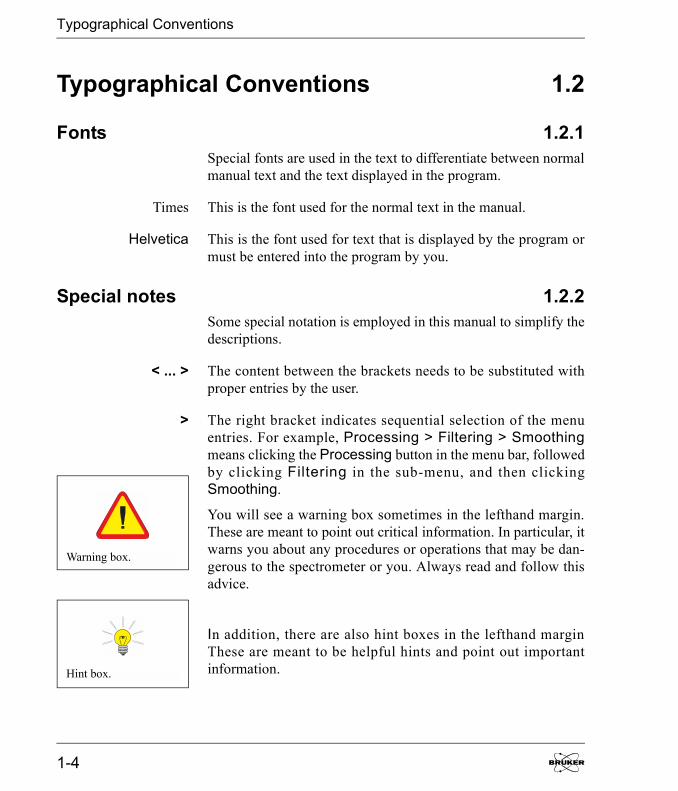
Fonts 1.2.1Special fonts are used in the text to differentiate between normalmanual text and the text displayed in the program.
Times This is the font used for the normal text in the manual.
Helvetica This is the font used for text that is displayed by the program ormust be entered into the program by you.
Special notes 1.2.2Some special notation is employed in this manual to simplify thedescriptions.
< ... > The content between the brackets needs to be substituted withproper entries by the user.
> The right bracket indicates sequential selection of the menuentries. For example, Processing > Filtering > Smoothingmeans clicking the Processing button in the menu bar, followedby clicking Filtering in the sub-menu, and then clickingSmoothing.
You will see a warning box sometimes in the lefthand margin.These are meant to point out critical information. In particular, itwarns you about any procedures or operations that may be dan-gerous to the spectrometer or you. Always read and follow thisadvice.
In addition, there are also hint boxes in the lefthand marginThese are meant to be helpful hints and point out importantinformation.
Warning box.
Hint box.
1-4

EPR Spectrometer Calibration 2For many experiments, it is vital that your spectrometer is care-fully calibrated. For example, it is essential to know the precisevalues of the magnetic field modulation amplitude in order toobtain quantitative EPR spectra. The calibration procedures inthis chapter enable you to measure the experimental conditionsproduced by the spectrometer with considerable accuracy.
This chapter is not meant to be a general overview of spectrome-ter calibration and quantitative EPR. Therefore, we highly rec-ommend the following references which discuss the topic inmuch greater detail:
� Poole, C.P. Electron Spin Resonance, a Comprehensive Trea-tise on Experimental Techniques: First Ed., Interscience,New York, 1967.
� Poole, C.P. Electron Spin Resonance, a Comprehensive Trea-tise on Experimental Techniques: Second Ed., Wiley, NewYork, 1983.
� Alger, R.S. Electron Paramagnetic Resonance: Interscience,New York, 1968.
Elexsys E 500 User�s Manual: Advanced Operations
Standard Samples
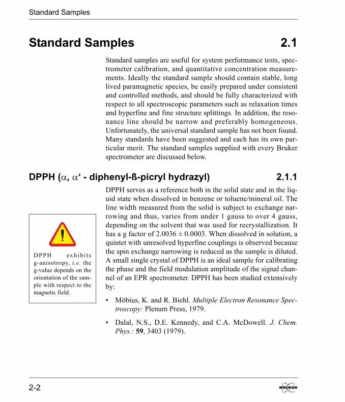
Standard Samples 2.1Standard samples are useful for system performance tests, spec-trometer calibration, and quantitative concentration measure-ments. Ideally the standard sample should contain stable, longlived paramagnetic species, be easily prepared under consistentand controlled methods, and should be fully characterized withrespect to all spectroscopic parameters such as relaxation timesand hyperfine and fine structure splittings. In addition, the reso-nance line should be narrow and preferably homogeneous.Unfortunately, the universal standard sample has not been found.Many standards have been suggested and each has its own par-ticular merit. The standard samples supplied with every Brukerspectrometer are discussed below.
DPPH (�, �� - diphenyl-ß-picryl hydrazyl) 2.1.1DPPH serves as a reference both in the solid state and in the liq-uid state when dissolved in benzene or toluene/mineral oil. Theline width measured from the solid is subject to exchange nar-rowing and thus, varies from under 1 gauss to over 4 gauss,depending on the solvent that was used for recrystallization. Ithas a g factor of 2.0036 ± 0.0003. When dissolved in solution, aquintet with unresolved hyperfine couplings is observed becausethe spin exchange narrowing is reduced as the sample is diluted.A small single crystal of DPPH is an ideal sample for calibratingthe phase and the field modulation amplitude of the signal chan-nel of an EPR spectrometer. DPPH has been studied extensivelyby:
� Möbius, K. and R. Biehl. Multiple Electron Resonance Spec-troscopy: Plenum Press, 1979.
� Dalal, N.S., D.E. Kennedy, and C.A. McDowell. J. Chem.Phys.: 59, 3403 (1979).
DPPH exh ib i t sg-anisotropy, i.e. theg-value depends on theorientation of the sam-ple with respect to themagnetic field.
2-2

Standard Samples
� Hyde, H.S., R.C. Sweed, Jr., and G.H. Rist. J. Chem. Phys.:51, 1404 (1969).
� Dalal, N.S., D.E. Kennedy, and C.A. McDowell. J. Chem.Phys.: 61, 1989 (1974).
� Dalal, N.S., D.E.Kennedy, and C.A. McDowell. Chem. Phys.Lett.: 30, 186 (1975).
Weak and Strong Pitch Samples 2.1.2Pitch in KCl has emerged as a standard because of its long-livedparamagnetic radicals and low dielectric loss. Because of thelong life of the radicals, it is unsurpassed as a test of spectrome-ter sensitivity. The pitch is added to a powder of KCl and themixture is carefully mechanically mixed to obtain a homoge-neous sample. After mixing, the sample is heated, pumped, andsealed under vacuum. Pitch is generally prepared in two concen-trations: strong pitch which is 0.11% pitch in KCl, and weakpitch which is 0.0003% pitch in KCl.
To correct for variations in spin concentration, each weak pitchsample is compared to a �standard� and assigned a correctionfactor. The peak to peak line width is typically 1.7 G with ag-factor of 2.0028. The size (very weak) of the signal renderspitch ill suited for modulation amplitude calibration. The weakpitch samples from Bruker Biospin have an estimated concentra-tion of 1013 spins per centimeter. The samples are calibrated andthe correction factor is printed on the side of the tube. This sam-ple is prepared for the purpose of measuring instrument perfor-mance owing to its high stability, however, it is not meant as aquantitative spin-counting standard.
Elexsys E 500 User�s Manual: Advanced Operations 2-3
Theory of Signal Channel Calibration
Theory of Signal Channel Calibration 2.2You need to carefully calibrate your spectrometer�s signal chan-nel reference phase and modulation amplitude in order to obtainmaximum sensitivity, minimum distortion, and quantitativelyreproducible measurements. The SCT/H and SCT/L signal chan-nels in conjunction with the Xepr software make this calibrationeasy to perform. The results of the calibration are saved on diskfor future use. We recommend recalibration at least once a yearto ensure quantitative and reproducible results. Each cavity orresonator has its own individual calibration file, therefore, thisprocedure must be followed for each cavity.
Introduction 2.2.1Calibration of the signal channel involves two separate yet inter-dependent procedures. The first procedure is to calibrate thepeak to peak modulation amplitude. For the sake of brevity,modulation amplitude will be used in place of peak to peak mod-ulation amplitude. The second procedure is to calibrate the phasedifference between the reference signal and the modulated EPRsignal. Because the calibration and adjustment of the modulationamplitude can affect the phase difference, the first procedure isperformed first.
2-4
Theory of Signal Channel Calibration
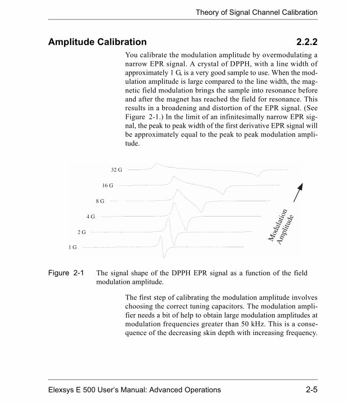
Amplitude Calibration 2.2.2You calibrate the modulation amplitude by overmodulating anarrow EPR signal. A crystal of DPPH, with a line width ofapproximately 1 G, is a very good sample to use. When the mod-ulation amplitude is large compared to the line width, the mag-netic field modulation brings the sample into resonance beforeand after the magnet has reached the field for resonance. Thisresults in a broadening and distortion of the EPR signal. (SeeFigure 2-1.) In the limit of an infinitesimally narrow EPR sig-nal, the peak to peak width of the first derivative EPR signal willbe approximately equal to the peak to peak modulation ampli-tude.
The first step of calibrating the modulation amplitude involveschoosing the correct tuning capacitors. The modulation ampli-fier needs a bit of help to obtain large modulation amplitudes atmodulation frequencies greater than 50 kHz. This is a conse-quence of the decreasing skin depth with increasing frequency.
Figure 2-1 The signal shape of the DPPH EPR signal as a function of the fieldmodulation amplitude.
Elexsys E 500 User�s Manual: Advanced Operations 2-5
Theory of Signal Channel Calibration
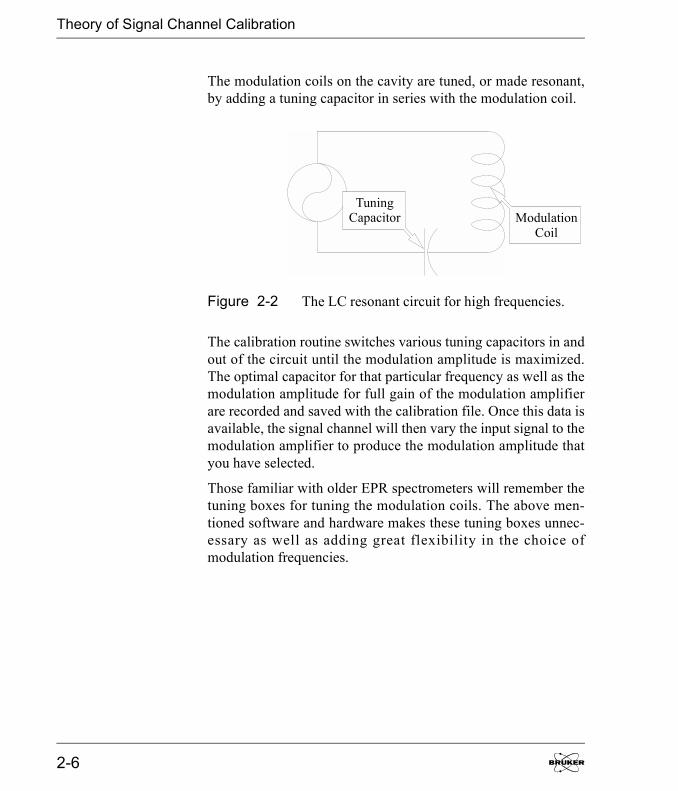
The modulation coils on the cavity are tuned, or made resonant,by adding a tuning capacitor in series with the modulation coil.
The calibration routine switches various tuning capacitors in andout of the circuit until the modulation amplitude is maximized.The optimal capacitor for that particular frequency as well as themodulation amplitude for full gain of the modulation amplifierare recorded and saved with the calibration file. Once this data isavailable, the signal channel will then vary the input signal to themodulation amplifier to produce the modulation amplitude thatyou have selected.
Those familiar with older EPR spectrometers will remember thetuning boxes for tuning the modulation coils. The above men-tioned software and hardware makes these tuning boxes unnec-essary as well as adding great flexibility in the choice ofmodulation frequencies.
Figure 2-2 The LC resonant circuit for high frequencies.
ModulationCoil
TuningCapacitor
2-6
Theory of Signal Channel Calibration
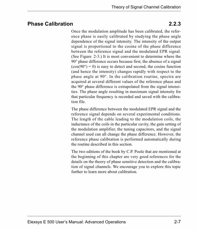
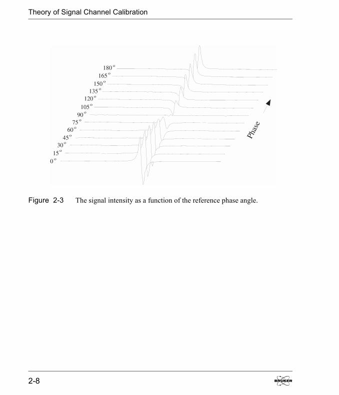
Phase Calibration 2.2.3Once the modulation amplitude has been calibrated, the refer-ence phase is easily calibrated by studying the phase angledependence of the signal intensity. The intensity of the outputsignal is proportional to the cosine of the phase differencebetween the reference signal and the modulated EPR signal.(See Figure 2-3.) It is most convenient to determine where the90� phase difference occurs because first, the absence of a signal(cos(90�) = 0) is easy to detect and second, the cosine function(and hence the intensity) changes rapidly with respect to thephase angle at 90�. In the calibration routine, spectra areacquired at several different values of the reference phase andthe 90� phase difference is extrapolated from the signal intensi-ties. The phase angle resulting in maximum signal intensity forthat particular frequency is recorded and saved with the calibra-tion file.
The phase difference between the modulated EPR signal and thereference signal depends on several experimental conditions.The length of the cable leading to the modulation coils, theinductance of the coils in the particular cavity, the gain setting ofthe modulation amplifier, the tuning capacitors, and the signalchannel used can all change the phase difference. However, thereference phase calibration is performed automatically duringthe routine described in this section.
The two editions of the book by C.P. Poole that are mentioned atthe beginning of this chapter are very good references for thedetails on the theory of phase sensitive detection and the calibra-tion of signal channels. We encourage you to explore this topicfurther to learn more about calibration.
Elexsys E 500 User�s Manual: Advanced Operations 2-7
Theory of Signal Channel Calibration
Figure 2-3 The signal intensity as a function of the reference phase angle.
2-8
Calibrating the Signal Channel
Calibrating the Signal Channel 2.31. Get ready for the calibration routine. Follow the
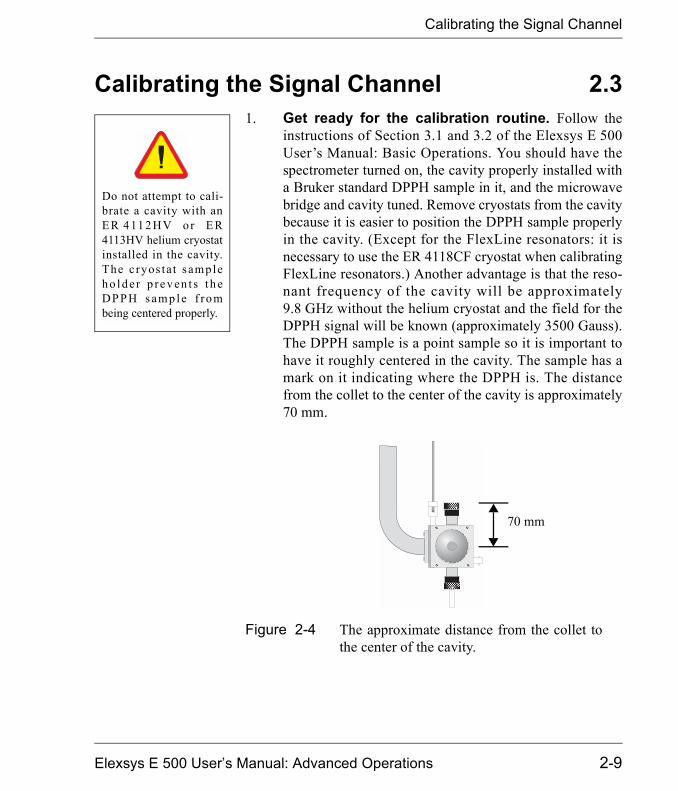
instructions of Section 3.1 and 3.2 of the Elexsys E 500User�s Manual: Basic Operations. You should have thespectrometer turned on, the cavity properly installed witha Bruker standard DPPH sample in it, and the microwavebridge and cavity tuned. Remove cryostats from the cavitybecause it is easier to position the DPPH sample properlyin the cavity. (Except for the FlexLine resonators: it isnecessary to use the ER 4118CF cryostat when calibratingFlexLine resonators.) Another advantage is that the reso-nant frequency of the cavity will be approximately9.8 GHz without the helium cryostat and the field for theDPPH signal will be known (approximately 3500 Gauss).The DPPH sample is a point sample so it is important tohave it roughly centered in the cavity. The sample has amark on it indicating where the DPPH is. The distancefrom the collet to the center of the cavity is approximately70 mm.
Figure 2-4 The approximate distance from the collet tothe center of the cavity.
Do not attempt to cali-brate a cavity with anE R 4 11 2 HV o r E R4113HV helium cryostatinstalled in the cavity.The c ryos ta t sampleh o l d er p re v en t s t h eDPPH s amp le f rombeing centered properly.
70 mm
Elexsys E 500 User�s Manual: Advanced Operations 2-9

Calibrating the Signal Channel
2. Create a calibration experiment. Click the NewExperiment button in the monitoring panel and the dialogbox will appear. (See Figure 2-5.) Enter a name for theexperiment (calibration for example) in the ExperimentName column. Click the Calib tab. Make sure the Stan-dard push button is activated (green). The R.F. button isfor ENDOR calibration. Click the Create button to closethe dialog box.
3. Open the parameter dialog box. Click the Parame-ter button to open the Calibration Parameters dialogbox. If the Calibration folder is not in front, click its tabto bring it to the front. (See Figure 2-6.)
Figure 2-5 Creating a calibration experiment.
Create anExperiment
SelectCalibrationClick
Create
2-10

Calibrating the Signal Channel
Figure 2-6 The Calibration Parameters dialog box.
SetFrequencyRange
TuningCapsSearch
AmplitudeSearch
PhaseSearch
ParameterButton
Elexsys E 500 User�s Manual: Advanced Operations 2-11

Calibrating the Signal Channel
4. Set the calibration frequency range. A calibrationis required for each modulation frequency that you intendto use. The SCT/H signal channel, has a range of 100 kHzto 6 kHz in 0.1 kHz steps. The SCT/L signal channel cov-ers the frequency range of 6 kHz to 100 Hz in 1 Hz steps.Most people will normally run all their spectra using100 kHz modulation, but under some special circum-stances, other frequencies may be desirable. A goodapproach to take is to calibrate the signal channel every 10kHz from 100 kHz to 10 kHz. A sufficiently large rangeof frequencies is then covered for most EPR experiments.Enter the Mod. Frequency Start [kHz] (usually100 kHz), Mod. Frequency End [kHz] as well as theMod. Frequency Increment [kHz] values. The startvalue must be greater than the end value . (SeeFigure 2-6.) Note that you should set the start and endvalues equal to each other for ER 4122SHQE orER 4119HS cavities so that only one frequencies at a timeis calibrated. (See the warning in the lefthand margin.)
5. Set initial values for the tuning caps search. Theparameters in this section set the starting values for thetuning capacitor search. (See Figure 2-6.) The InitialModulation Amplitude defines the modulation amplitudeused when optimizing the tuning capacitors. The defaultvalue, 10%, is appropriate for most cavities and resona-tors. The default Initial Sweep Width of 20 G works wellfor a DPPH sample. If you know an approximate optimalvalue for the tuning capacitors at 100 kHz, you can enterthat value in Tuning C Start Value. This will save youtime because otherwise the searching routine will startfrom 0 nF. Mod Frequency Limit is always set at 50 kHzbecause skin depth poses less of a problem at lower fre-quencies.
The EN 801 ENDORresonator should not beused above 25 kHz.Consult the ElexsysE 560 documentationfor instructions on cali-brating this cavity.
The ER 4122SHQEand ER 4119HS reso-nators should only becalibrated one modula-t ion f requency a t atime! At lower modula-tion frequencies, themodulation amplitudecan get sufficient lylarge to damage thecoils. The Mod. Ampli-tude Limit needs to beadjusted separately foreach modulation fre-quency.
2-12

Calibrating the Signal Channel
6. Adjust the Mod. Amplitude Limit. The Mod. Ampli-tude Limit parameter limits the size of the signal sent tothe modulation amplifier. This prevents damage to thecoils owing to excessive current. Enter a value of 75% foran ER 4122 SHQ cavity. For Flex-line resonators, a valueof 10% is more appropriate. A value of 30% works wellfor ER 4122SHQE and ER 4119HS cavities. It is alwayssafe to set this value a bit low as you will adjust this valuelater. A 100 G Sweep Width is sufficient for most reso-nators. (See Figure 2-6.)
7. Enter values for the modulation phase search.The parameters in this step depend on your calibrationsample. The default values of 1 G Sample Line Widthand 20 G Sweep Width work well with the Bruker DPPHstandard. The signal channel can produce either a firstharmonic (first derivative) or a second harmonic (secondderivative) spectrum. If you have no need for second har-monic spectra and wish to save a bit of time in the calibra-tion routine, you may deselect this option by clicking theCalibrate 2nd Harmonic button. The green color indi-cates that the option is selected. (See Figure 2-6.)
8. Enter the filename for the calibration file. Click theResults tab. (See Figure 2-7.) The calibration file nameusually consists of two to four letters that identify the typeo f c a v i t y ( S T f o r E R 4 1 0 2 S T o r S H Q E f o rER 4122SHQE) followed by the serial number of the cav-ity. This number is found on the back or front of the cav-ity. For FlexLine series resonators the serial number isfound at the top part of the module block. Enter the cali-bration file name into the Calibration Data Set box. Ifyou are re-calibrating, you can click the file name in thedrop down list of the Calibration Data Set. The new val-ues will be appended to the calibration file or replace pre-vious values in the file. If you want to start fresh, click theDelete Data Set button to delete the old calibration data.
It is not necessary tocalibrate every 100 Hzfrom 100 kHz to 10kHz. In pa r t i cu l a r,FlexLine resonators ina cryostat with no gasflow can become suffi-ciently warm to dam-age the resonator if youcalibrate more than 20f req u en c i e s i n o neexperiment.
Better safe than sorry.It is a good idea to cali-brate the phase of thesecond harmonic whenrunning the calibrationroutine.
Elexsys E 500 User�s Manual: Advanced Operations 2-13
Calibrating the Signal Channel
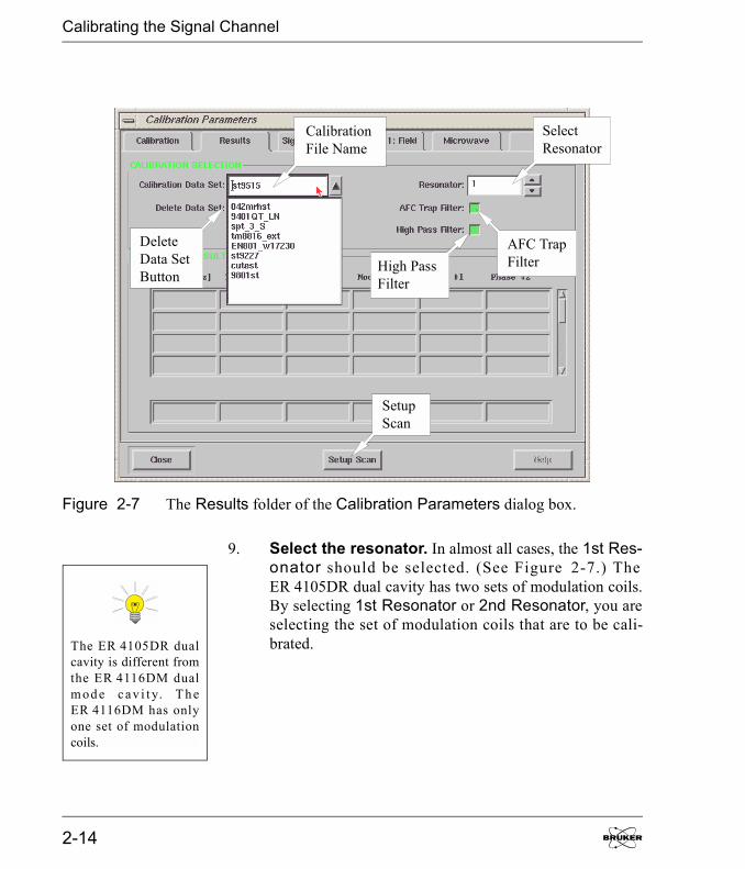
9. Select the resonator. In almost all cases, the 1st Res-onator should be selected. (See Figure 2-7.) TheER 4105DR dual cavity has two sets of modulation coils.By selecting 1st Resonator or 2nd Resonator, you areselecting the set of modulation coils that are to be cali-brated.
Figure 2-7 The Results folder of the Calibration Parameters dialog box.
SelectResonator
AFC TrapFilterHigh Pass
Filter
SetupScan
DeleteData SetButton
CalibrationFile Name
The ER 4105DR dualcavity is different fromthe ER 4116DM dualm od e c av i t y. T h eER 4116DM has onlyone set of modulationcoils.
2-14

Calibrating the Signal Channel
10. Turn on the AFC Trap and High Pass Filters. TheAFC trap filter blocks any signal components at the AFCmodulation frequency that may contribute to noise in theEPR signal. The high pass filter suppresses low frequencysignal components that also contribute to added noise inthe EPR signal. These two filters influence the calibrationvalues of the signal channel. By default they are bothselected. Ensure that both options are selected. (SeeFigure 2-7.) Only under very rare circumstances wouldyou acquire spectra without these filters.
11. Start the Setup Scan. When the Setup Scan functionis activated, the magnetic field is swept rapidly (up to 50Gauss at about a 30 Hz rate) to provide a �real time� dis-play of the EPR spectrum on the screen. Click the SetupScan button in the Results folder. (See Figure 2-7.)
Figure 2-8 The Setup Scan window.
Activate Button
Setup ScanButton Setup Scan
Time Constant
Elexsys E 500 User�s Manual: Advanced Operations 2-15

Calibrating the Signal Channel
A Setup Scan window will appear. Click the Activatebutton in the monitoring panel if it is not already acti-vated. Then click the Setup Scan button in the SetupScan window to activate it. (See Figure 2-8.) Leave thiswindow open so you can adjust the parameters interac-tively.
12. Set the Microwave Attenuator to approximately25 dB. Click the Microwave tab. Set the microwavepower to 25 dB. (See Figure 2-9.)
Figure 2-9 The Microwave folder of the Calibration Parameter dialog box.
2-16
Calibrating the Signal Channel
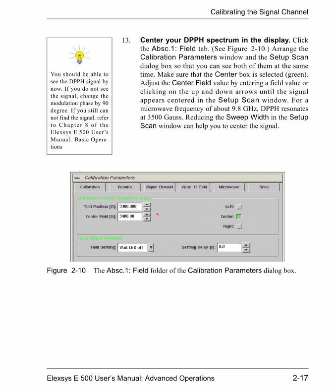
13. Center your DPPH spectrum in the display. Clickthe Absc.1: Field tab. (See Figure 2-10.) Arrange theCalibration Parameters window and the Setup Scandialog box so that you can see both of them at the sametime. Make sure that the Center box is selected (green).Adjust the Center Field value by entering a field value orclicking on the up and down arrows until the signalappears centered in the Setup Scan window. For amicrowave frequency of about 9.8 GHz, DPPH resonatesat 3500 Gauss. Reducing the Sweep Width in the SetupScan window can help you to center the signal.
You should be able tosee the DPPH signal bynow. If you do not seethe signal, change themodulation phase by 90degree. If you still cannot find the signal, referto Chapte r 8 o f t heElexsys E 500 User�sManual: Basic Opera-tions
Figure 2-10 The Absc.1: Field folder of the Calibration Parameters dialog box.
Elexsys E 500 User�s Manual: Advanced Operations 2-17

Calibrating the Signal Channel
14. Adjust other parameters. Adjust the Receiver Gainso that the signal fills approximately half of the verticaldisplay range in the Setup Scan window. Make sure thatthe signal channel is set to 100 kHz modulation (or themaximum modulation frequency you entered in the Cali-bration folder) and first harmonic detection. A 1 gaussModulation Amplitude usually is sufficient.
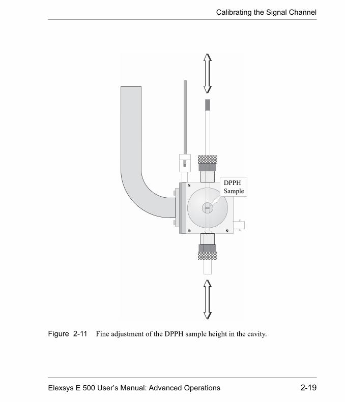
15. Optimize the DPPH sample position. Move thesample tube up and down until the maximum signal inten-sity is attained. (See Figure 2-11.) Avoid moving thesample from side to side. Perhaps the best technique is toloosen the collet nuts for the pedestal and sample tube andmove the sample too low. Then use the pedestal to slowlypush the sample up. Sometimes the process of moving thesample tube in the cavity can cause the AFC to lose lock.Re-tune the frequency if this happens. If the signal isclipped, decrease the Receiver Gain. Rotate the sampletube until the maximum signal intensity is attained. Whenyou have maximized the signal intensity, secure the sam-ple tube by tightening the collet nuts. Check the matchingif needed. You may need to re-center the signal by adjust-ing the Center Field in the Absc.1: Field tab.
The EN 801 ENDORresonator should not beused above 25 kHz.Consult the ElexsysE 560 documentationfor instructions on cali-brating this cavity.
2-18
Calibrating the Signal Channel
Figure 2-11 Fine adjustment of the DPPH sample height in the cavity.
DPPHSample
Elexsys E 500 User�s Manual: Advanced Operations 2-19
Calibrating the Signal Channel
16. Close the Setup Scan window. Click the Close but-ton in the Setup Scan window.
17. Reset some parameters. After centering the DPPHsample, most of the parameters should be fairly close towhat is needed for the calibration routine. Set theReceiver Gain to approximately 36 dB.
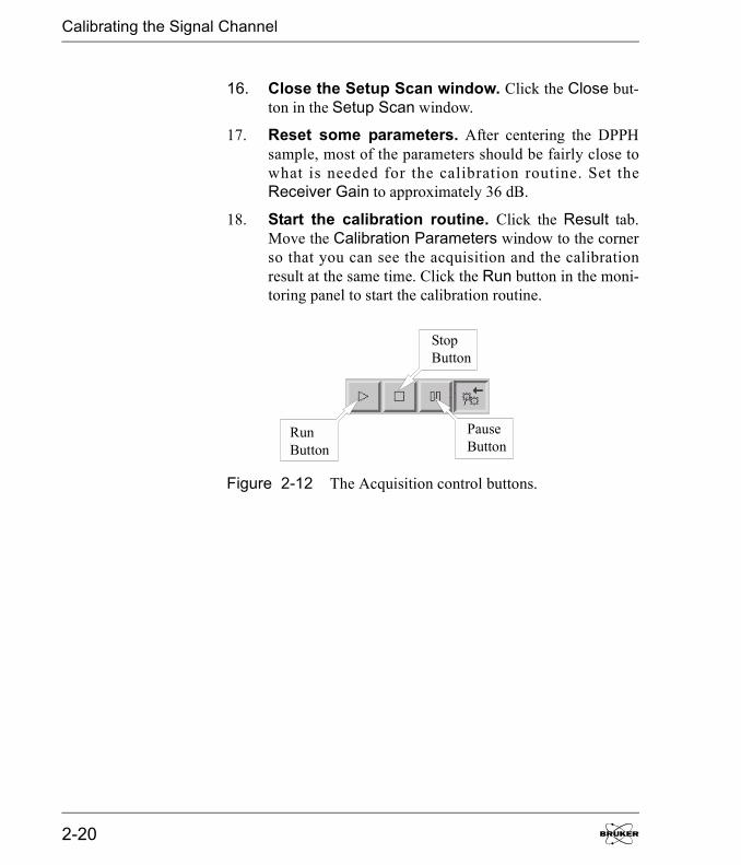
18. Start the calibration routine. Click the Result tab.Move the Calibration Parameters window to the cornerso that you can see the acquisition and the calibrationresult at the same time. Click the Run button in the moni-toring panel to start the calibration routine.
Figure 2-12 The Acquisition control buttons.
RunButton
PauseButton
StopButton
2-20
Calibrating the Signal Channel
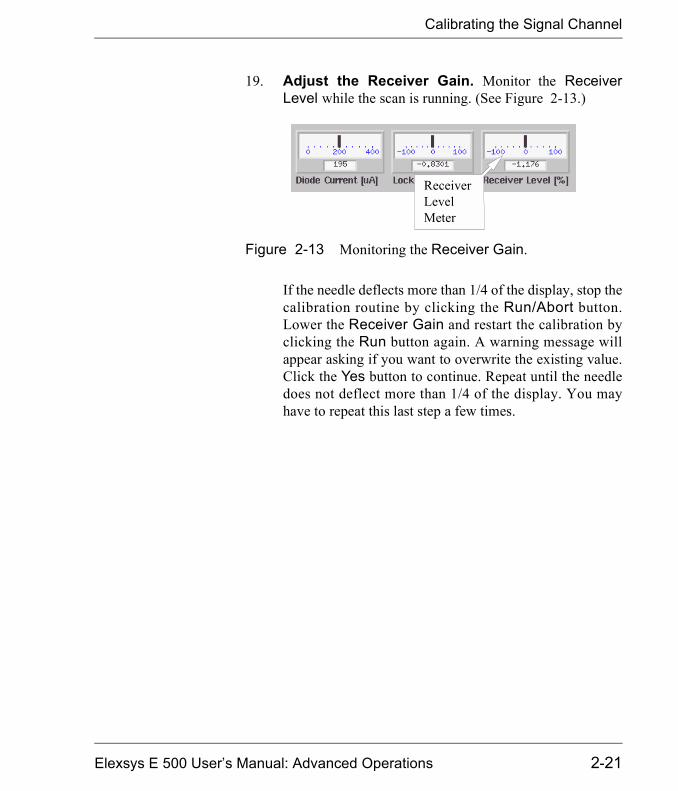
19. Adjust the Receiver Gain. Monitor the ReceiverLevel while the scan is running. (See Figure 2-13.)
If the needle deflects more than 1/4 of the display, stop thecalibration routine by clicking the Run/Abort button.Lower the Receiver Gain and restart the calibration byclicking the Run button again. A warning message willappear asking if you want to overwrite the existing value.Click the Yes button to continue. Repeat until the needledoes not deflect more than 1/4 of the display. You mayhave to repeat this last step a few times.
Figure 2-13 Monitoring the Receiver Gain.
ReceiverLevelMeter
Elexsys E 500 User�s Manual: Advanced Operations 2-21

Calibrating the Signal Channel
20. Observe the calibration results. The Results folderconsists of a table of parameter values and settings foreach modulation frequency. The first column is the modu-lation frequency. For modulation frequencies greater thanor equal to 50 kHz, the optimal tuning capacitor value islisted in the second column. The third column contains thevalue of Mod Amp [% max]. Mod Amp [G] in the fourthcolumn is the measured maximum modulation amplitudewhen the corresponding Mod Amp [% max] is used.Phase #1 and Phase #2, in columns five and six respec-tively, are the phases at which the first and second har-monic signals are nulled. (See Figure 2-14.)
Figure 2-14 The calibration results.
2-22

Calibrating the Signal Channel
21. Check the Mod. Amp [G] at 100 kHz. The calibrationroutine performs its task sequentially, starting with thehighest modulation frequency and continuing for eachselected modulation frequency. As each parameter isdetermined, it is displayed in the table. (See Figure 2-14.)Wait until the 100 kHz calibration is completed. Click thePause button of the Acquisition Control buttons. Notethe value in the fourth column of the table, Mod Amp [G].Compare the Mod Amp [G] at 100 kHz with the valueslisted for your cavity in Table 2-1. If the value obtained bythe calibration routine is slightly less than or approxi-mately equal to the value listed in Table 2-1, allow the cal-ibration routine to continue its task by clicking the Pausebutton again and proceed to Step 23. If the value exceedsthe values listed in Table 2-1, stop the calibration routineby clicking the Run/Abort button in the AcquisitionControl buttons. Values that are too high can allow exces-sive current to flow through the modulation coils of thecavity at the maximum modulation amplitude, resulting indamaged modulation coils.
Elexsys E 500 User�s Manual: Advanced Operations 2-23

Calibrating the Signal Channel
Cavity Maximum Mod. / Gauss at 100 kHz
ER 4102ST 32ER 4105DR 32ER 4104OR 32ER 4116DM 10ER 4103TM 16ER 4108TMH 32ER 4106ZRC 10ER 4106ZRAC 10ER 4107WZC 10ER 4107WZAC 10ER 4115ODC 10ER 4115ODAC 10ER 4119HS 25ER 4122SHQ 15ER 4122SHQE 25ER 4114HT 7ER 4117MX (or D-MVT)
10
ER 4117D-R 32ER 4109EF 10
Table 2-1 Maximum modulation amplitude for EPR cavities.
2-24

Calibrating the Signal Channel
22. Reset the Mod. Amplitude Limit. The Mod. Ampli-tude Limit parameter which was set in Step 6. limits thesize of the signal sent to the modulation amplifier to pre-vent any danger of burning out the modulation coils. Tocalculate a safer value for Mod. Amplitude Limit use thefollowing formula:
Mod Amplitude Limit = Mod Amp[%max]
where Mod Amp[%max] and Mod. Amp [G] are the val-ues listed in the calibration table and Max. Mod. is themaximum modulation amplitude listed for your cavity inTable 2-1. Enter this new value for Mod. AmplitudeLimit in the Calibration tab. Click the Results tab tobring it to the front. Click the Run button to restart thecalibration routine.
23. Finish the calibration. When the routine is finished theRun button will no longer be highlighted and the calibra-tion data for the lowest modulation frequency is com-pleted. (I.e. the calibration data in the Results tab are nolonger -1.)
24. Special Instructions for ER 4122SHQE andER 4119HS cavities. It was mentioned on page 12 thatthese cavities should be calibrated one frequency at atime. An additional requirement is that the Mod. Ampli-tude Limit be set properly at each modulation frequency.Follow Step 21. and Step 22. for each of the individualmodulation frequencies after you have started the calibra-tion routine for that frequency.
Max. Mod.Mod. Amp [G]------------------------------------
Elexsys E 500 User�s Manual: Advanced Operations 2-25
Calibrating the Signal Channel
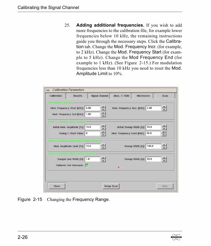
25. Adding additional frequencies. If you wish to addmore frequencies to the calibration file, for example lowerfrequencies below 10 kHz, the remaining instructionsguide you through the necessary steps. Click the Calibra-tion tab. Change the Mod. Frequency Incr. (for example,to 2 kHz). Change the Mod. Frequency Start (for exam-ple to 5 kHz). Change the Mod Frequency End (forexample to 1 kHz). (See Figure 2-15.) For modulationfrequencies less than 10 kHz you need to reset the Mod.Amplitude Limit to 10%.
Figure 2-15 Changing the Frequency Range.
2-26

Calibrating the Signal Channel
26. Start the calibration routine. Click the Run button tostart the calibration routine. The low modulation fre-quency calibration data will be appended to the table. Ifthere is one or more calibration frequencies already exist-ing in the previous calibration file, a warning messagewill appear on the screen asking you if you want to over-write the existing value. Click the Yes or No button(depending on your wishes) to continue the calibrationroutine. Notice that the previous calibration data for otherfrequencies are still kept in the file.
27. Close the Calibration Parameters dialog box.Click the Close button in the Calibration Parametersdialog box. The signal channel is now calibrated for yourcavity and the data saved in the calibration file. The nexttime when you connect the Xepr software to the spec-trometer, this calibration file will be the default calibra-tion file.
Elexsys E 500 User�s Manual: Advanced Operations 2-27

Notes
2-28

System Performance Tests 3This chapter describes procedures for testing the performance ofyour Bruker EPR spectrometer. The test measures the spectrom-eter's sensitivity. The procedure is especially designed to test asmany of the components of the spectrometer as possible withone simple test. It therefore gives you a good indication of theoverall health of your spectrometer. It is also an excellent crite-rion for comparing the sensitivity of different spectrometers.Should your spectrometer or cavity not meet specifications, firstconsult Chapter 9 of the Elexsys E 500 User�s Manual: BasicOperations on troubleshooting. If none of the hints solve theproblem, contact your Bruker EPR service representative.
Elexsys E 500 User�s Manual: Advanced Operations

Signal to Noise Ratio Test
Signal to Noise Ratio Test 3.1The signal to noise ratio test is an important part in maintainingyour spectrometer. It is also helpful in diagnosing possible prob-lems you may encounter especially when you deal with veryweak signals or quantify your EPR signals. The signal to noiseratio test uses the ER 4122SHQ or ER 4122SHQE cavity and theweak pitch sample that was shipped with your spectrometer. Thetest measures the EPR signal intensity (peak-to-peak height) ofthe weak pitch sample at low microwave power (23 dB) andthen measures the noise level under the same conditions excepthigher microwave power (0 dB) and higher receiver gain tocharacterize the noise better. The formula for calculation of thesignal to noise ratio is:
, [3-1]
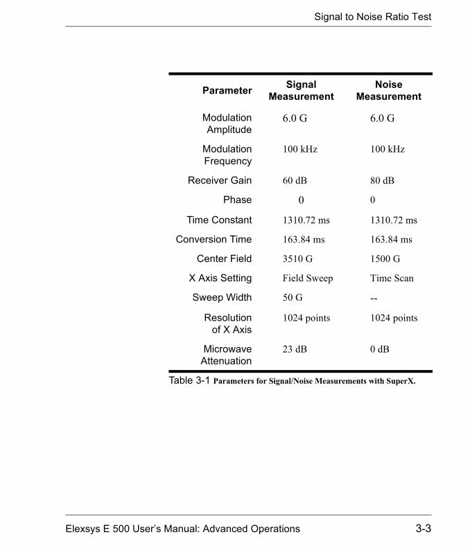
where AS and AN are the peak to peak height of the weak pitchand amplitude of the noise respectively. GS and GN are thereceiver gains used in signal and noise measurements respec-tively. We use their ratio to correct for the gain difference. PSand PN are the powers used in two measurements and we use thesquare root of the ratio of powers to correct for the power differ-ence. The factor of 2.5 translates the peak-to-peak noise level toa RMS (Root Mean Square) noise level. T is the time constant(in seconds) and we use the square root of the time constant tonormalize the S/N to a one second time constant. C is the weakpitch correction factor that is printed on the label of the weakpitch sample. The standard instrument settings for signal andnoise measurements are listed in Table 3-1.
SN----
ASAN-------
GNGS-------
PNPS------- 2.5
T C�
-----------------���=
3-2
Signal to Noise Ratio Test
Parameter Signal Measurement
Noise Measurement
ModulationAmplitude
6.0 G 6.0 G
ModulationFrequency
100 kHz 100 kHz
Receiver Gain 60 dB 80 dB
Phase 0 0
Time Constant 1310.72 ms 1310.72 ms
Conversion Time 163.84 ms 163.84 ms
Center Field 3510 G 1500 G
X Axis Setting Field Sweep Time Scan
Sweep Width 50 G --
Resolutionof X Axis
1024 points 1024 points
MicrowaveAttenuation
23 dB 0 dB
Table 3-1 Parameters for Signal/Noise Measurements with SuperX.
Elexsys E 500 User�s Manual: Advanced Operations 3-3
Signal to Noise Ratio Test
Preparing for the S/N Test 3.1.11. Install an ER 4122SHQ or ER 4122SHQE cavity.
(See Section 7.2 of the Elexsys E 500 User�s Manual:Basic Operations for instructions.) The specification forthe signal to noise ratio is based on an ER 4122SHQ orER 4122SHQE cavity using the weak pitch sample. Westrongly suggest using this cavity for the standard test andkeep a record and verify the specification periodically. Ifyou use other types of cavities to do the signal to noiseratio test the results and the settings will be different dueto different Q values and the microwave field distribu-tions of the cavities.
2. Insert the weak pitch sample. Copy down the cali-bration factor posted on the label of the weak pitch samplebefore you insert it. The weak pitch sample should beinserted in the cavity until the bottom of the label and tapeon the sample tube is flush with the collet. You alsoshould use the pedestal to hold the weak pitch sample rig-idly.
3. Turn on the instrument and tune. Turn on the instru-ment if it is not on yet. Tune the microwave bridge and thecavity. It is best to wait several hours to let the spectrome-ter fully warm up because the spectrometer is most sensi-tive and stable after it has achieved thermal equilibrium.
4. Optimize the AFC. Refer to Section 7.3.2. of the Elex-sys E 500 User�s Manual: Basic Operations for instruc-tions or hints.
5. Check the Spectrometer Configuration. ClickSpectrometer Configuration in the Acquisition menuand click the Signal Channel tab. Make sure you havethe correct calibration file for the cavity you are using.High Pass Filter and AFC Trap Filter should be acti-
Yo u ne e d to p urg enitrogen gas throughthe cavity to avoid pos-sible oxygen signalsowing to the high sen-sitivity of the cavity
The calibration factoris found on the weakpitch sample�s label. Itis listed as:
C = C0 x calibration factor
It is usually approxi-mately equal to one andcorrects for variationsin the sample concen-tration.
3-4
Signal to Noise Ratio Test
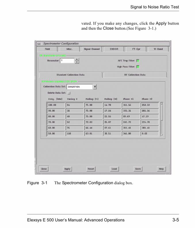
vated. If you make any changes, click the Apply buttonand then the Close button.(See Figure 3-1.)
Figure 3-1 The Spectrometer Configuration dialog box.
Elexsys E 500 User�s Manual: Advanced Operations 3-5
Signal to Noise Ratio Test
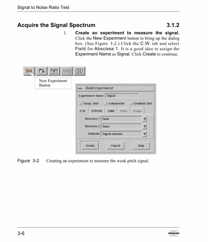
Acquire the Signal Spectrum 3.1.21. Create an experiment to measure the signal.
Click the New Experiment button to bring up the dialogbox. (See Figure 3-2.) Click the C.W. tab and selectField for Abscissa 1. It is a good idea to assign theExperiment Name as Signal. Click Create to continue.
Figure 3-2 Creating an experiment to measure the weak pitch signal.
New ExperimentButton
3-6
Signal to Noise Ratio Test
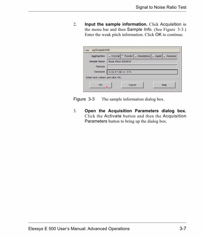
2. Input the sample information. Click Acquisition inthe menu bar and then Sample Info. (See Figure 3-3.)Enter the weak pitch information. Click OK to continue.
3. Open the Acquisition Parameters dialog box.Click the Activate button and then the AcquisitionParameters button to bring up the dialog box.
Figure 3-3 The sample information dialog box.
Elexsys E 500 User�s Manual: Advanced Operations 3-7
Signal to Noise Ratio Test
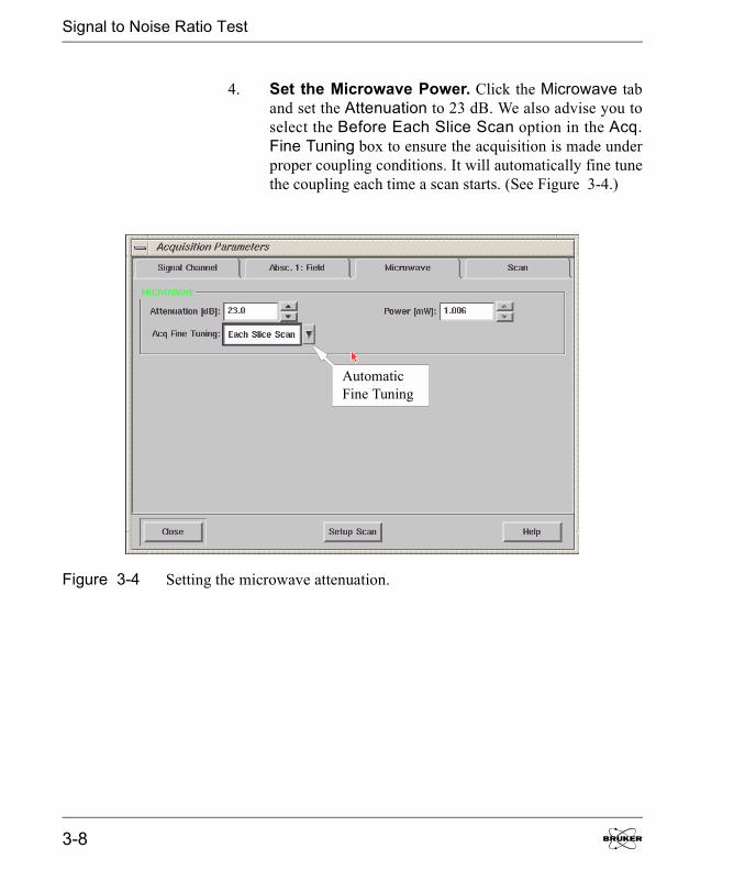
4. Set the Microwave Power. Click the Microwave taband set the Attenuation to 23 dB. We also advise you toselect the Before Each Slice Scan option in the Acq.Fine Tuning box to ensure the acquisition is made underproper coupling conditions. It will automatically fine tunethe coupling each time a scan starts. (See Figure 3-4.)
Figure 3-4 Setting the microwave attenuation.
AutomaticFine Tuning
3-8
Signal to Noise Ratio Test
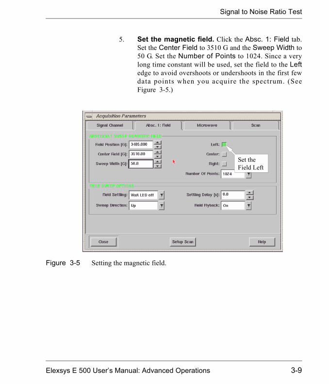
5. Set the magnetic field. Click the Absc. 1: Field tab.Set the Center Field to 3510 G and the Sweep Width to50 G. Set the Number of Points to 1024. Since a verylong time constant will be used, set the field to the Leftedge to avoid overshoots or undershoots in the first fewdata points when you acquire the spectrum. (SeeFigure 3-5.)
Figure 3-5 Setting the magnetic field.
Set theField Left
Elexsys E 500 User�s Manual: Advanced Operations 3-9
Signal to Noise Ratio Test
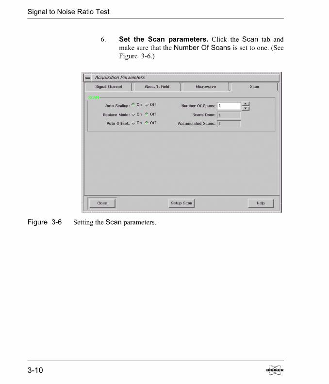
6. Set the Scan parameters. Click the Scan tab andmake sure that the Number Of Scans is set to one. (SeeFigure 3-6.)
Figure 3-6 Setting the Scan parameters.
3-10
Signal to Noise Ratio Test
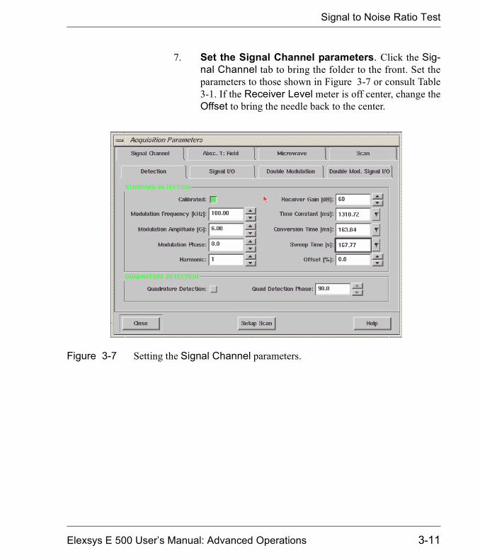
7. Set the Signal Channel parameters. Click the Sig-nal Channel tab to bring the folder to the front. Set theparameters to those shown in Figure 3-7 or consult Table3-1. If the Receiver Level meter is off center, change theOffset to bring the needle back to the center.
Figure 3-7 Setting the Signal Channel parameters.
Elexsys E 500 User�s Manual: Advanced Operations 3-11

Signal to Noise Ratio Test
8. Acquire a signal spectrum. Click the Run button toacquire a spectrum. It should look similar to Figure 3-8.
9. Store the signal spectrum. Click on the PrimaryProperties menu, select Store in the drop down menu tostore the spectrum in memory. Name the spectrum andstore it.
Figure 3-8 The weak pitch signal.
3-12
Signal to Noise Ratio Test
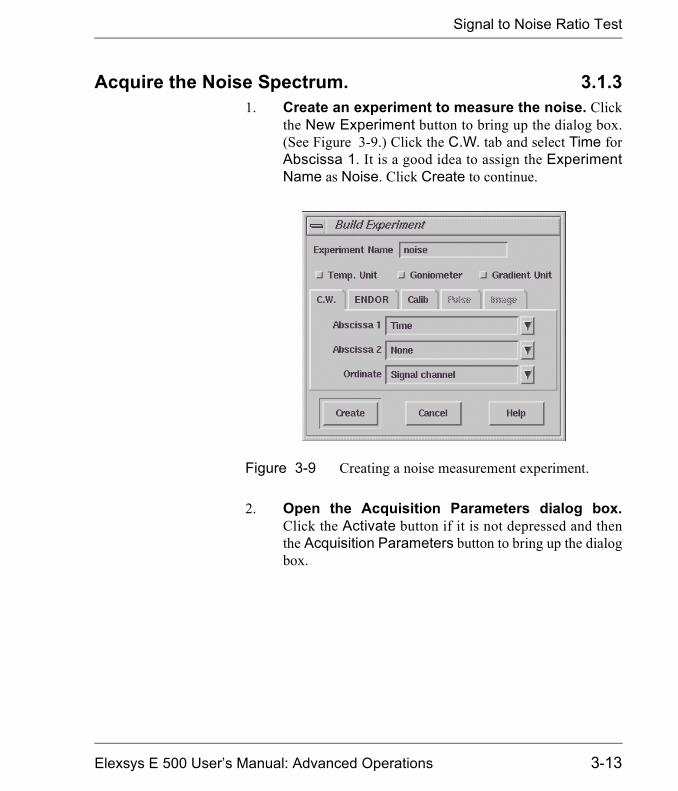
Acquire the Noise Spectrum. 3.1.31. Create an experiment to measure the noise. Click
the New Experiment button to bring up the dialog box.(See Figure 3-9.) Click the C.W. tab and select Time forAbscissa 1. It is a good idea to assign the ExperimentName as Noise. Click Create to continue.
2. Open the Acquisition Parameters dialog box.Click the Activate button if it is not depressed and thenthe Acquisition Parameters button to bring up the dialogbox.
Figure 3-9 Creating a noise measurement experiment.
Elexsys E 500 User�s Manual: Advanced Operations 3-13
Signal to Noise Ratio Test
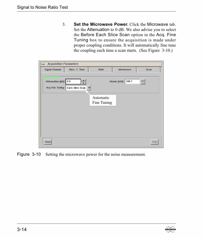
3. Set the Microwave Power. Click the Microwave tab.Set the Attenuation to 0 dB. We also advise you to selectthe Before Each Slice Scan option in the Acq. FineTuning box to ensure the acquisition is made underproper coupling conditions. It will automatically fine tunethe coupling each time a scan starts. (See Figure 3-10.)
Figure 3-10 Setting the microwave power for the noise measurement.
AutomaticFine Tuning
3-14
Signal to Noise Ratio Test
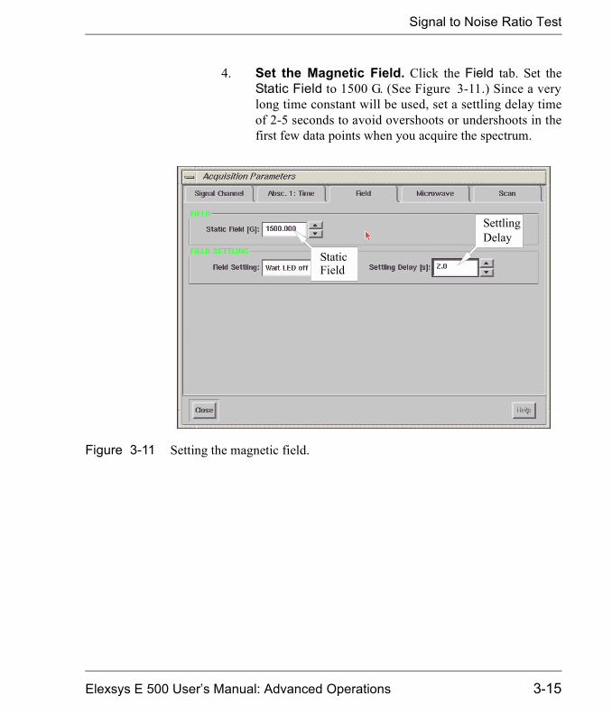
4. Set the Magnetic Field. Click the Field tab. Set theStatic Field to 1500 G. (See Figure 3-11.) Since a verylong time constant will be used, set a settling delay timeof 2-5 seconds to avoid overshoots or undershoots in thefirst few data points when you acquire the spectrum.
Figure 3-11 Setting the magnetic field.
StaticField
SettlingDelay
Elexsys E 500 User�s Manual: Advanced Operations 3-15

Signal to Noise Ratio Test
5. Set the time sweep parameters. Click the Absc 1:Time tab. Set the Number of Points to 1024. Set theSweep Time to 167.77 s. (See Figure 3-12.)
Figure 3-12 Setting parameters for the Absc.1: Time folder.
SweepTime
Numberof Points
3-16
Signal to Noise Ratio Test
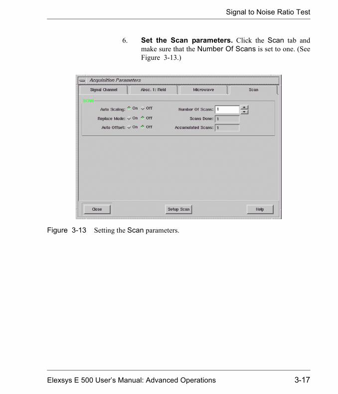
6. Set the Scan parameters. Click the Scan tab andmake sure that the Number Of Scans is set to one. (SeeFigure 3-13.)
Figure 3-13 Setting the Scan parameters.
Elexsys E 500 User�s Manual: Advanced Operations 3-17

Signal to Noise Ratio Test
7. Set the Signal Channel parameters. Click the Sig-nal Channel tab to bring the folder to the front. Set theparameters to those shown in Figure 3-14 or consultTable 3-1. If the Receiver Level meter is off center,change the Offset to bring the needle back to the center.
Figure 3-14 Setting the Signal Channel parameters.
3-18
Signal to Noise Ratio Test
8. Get ready to acquire a noise spectrum. Click theRUN button in the acquisition tool bar to acquire thenoise spectrum. Frequently the baseline will drift since200 mW microwave power is going to heat up the cavityand the sample. Wait a few minutes to achieve thermalequilibrium. Check the tuning and coupling of the system.Retune the system if necessary. You may also have arather large offset due to the excessive power and highgain. Adjust the offset so that the indicator of theReceiver Level meter is in the middle.
Elexsys E 500 User�s Manual: Advanced Operations 3-19

Signal to Noise Ratio Test
9. Acquire a noise spectrum. Click the RUN button inthe acquisition tool bar and acquire the noise spectrumagain. (See Figure 3-15.) If there is no baseline drift,store the spectrum and continue to the next section. Ifthere is drift, wait a bit longer and run the noise traceagain.
If there is a linear drift,you do no t need tore-acquire the noisespec trum. We shal lsubtract it out in thenext step
Figure 3-15 Acquiring a noise spectrum.
3-20
Signal to Noise Ratio Test
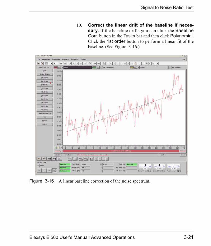
10. Correct the linear drift of the baseline if neces-sary. If the baseline drifts you can click the BaselineCorr. button in the Tasks bar and then click Polynomial.Click the 1st order button to perform a linear fit of thebaseline. (See Figure 3-16.)
Figure 3-16 A linear baseline correction of the noise spectrum.
Elexsys E 500 User�s Manual: Advanced Operations 3-21
Signal to Noise Ratio Test
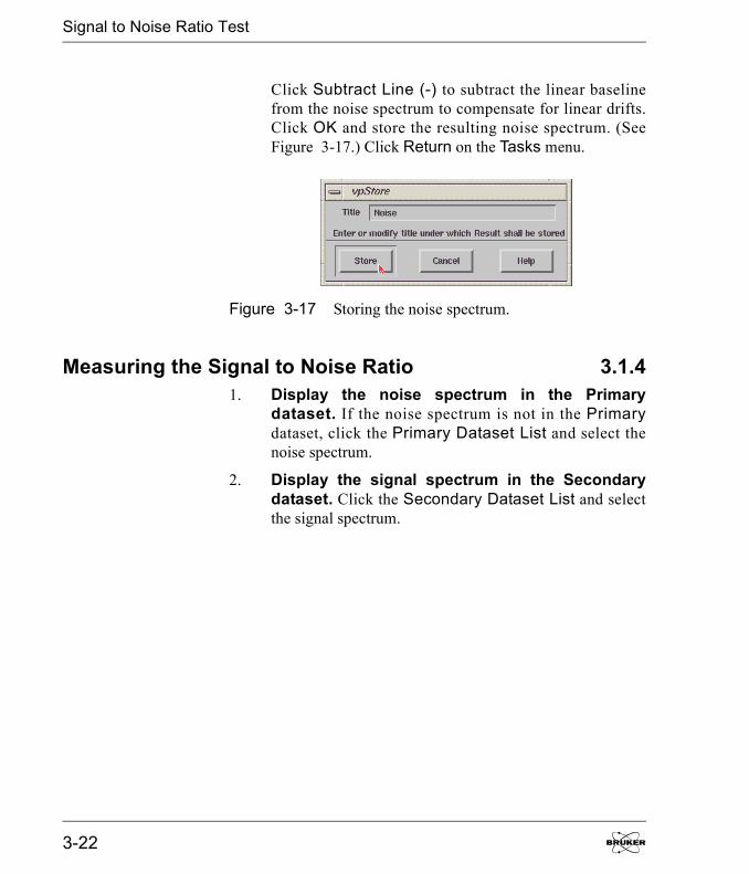
Click Subtract Line (-) to subtract the linear baselinefrom the noise spectrum to compensate for linear drifts.Click OK and store the resulting noise spectrum. (SeeFigure 3-17.) Click Return on the Tasks menu.
Measuring the Signal to Noise Ratio 3.1.41. Display the noise spectrum in the Primary
dataset. If the noise spectrum is not in the Primarydataset, click the Primary Dataset List and select thenoise spectrum.
2. Display the signal spectrum in the Secondarydataset. Click the Secondary Dataset List and selectthe signal spectrum.
Figure 3-17 Storing the noise spectrum.
3-22
Signal to Noise Ratio Test
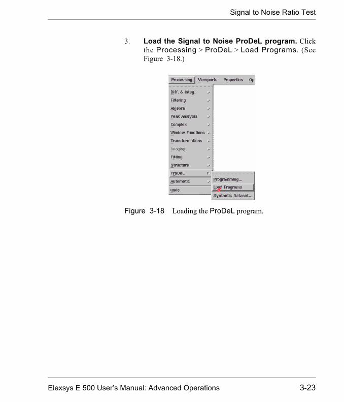
3. Load the Signal to Noise ProDeL program. Clickthe Processing > ProDeL > Load Programs. (SeeFigure 3-18.)
Figure 3-18 Loading the ProDeL program.
Elexsys E 500 User�s Manual: Advanced Operations 3-23
Signal to Noise Ratio Test
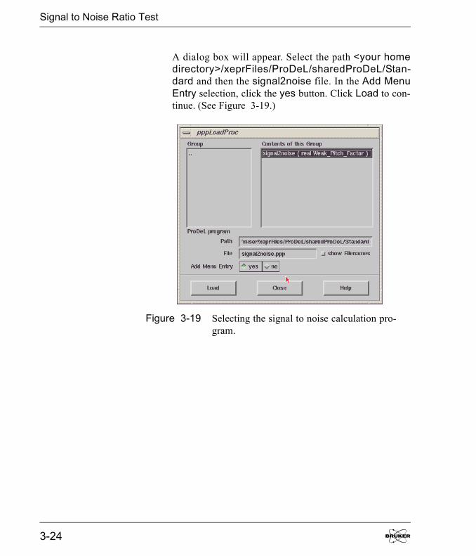
A dialog box will appear. Select the path <your homedirectory>/xeprFiles/ProDeL/sharedProDeL/Stan-dard and then the signal2noise file. In the Add MenuEntry selection, click the yes button. Click Load to con-tinue. (See Figure 3-19.)
Figure 3-19 Selecting the signal to noise calculation pro-gram.
3-24
Signal to Noise Ratio Test
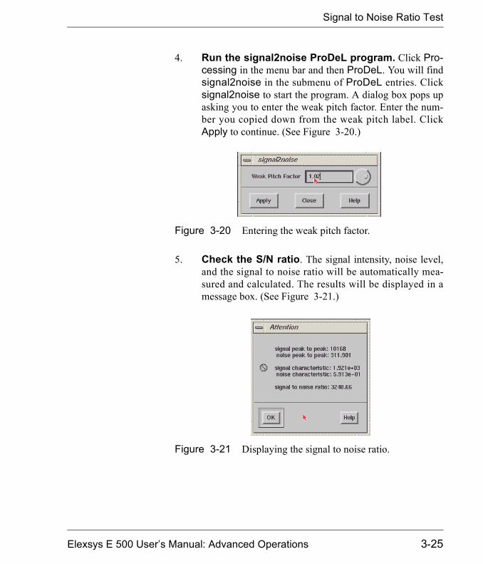
4. Run the signal2noise ProDeL program. Click Pro-cessing in the menu bar and then ProDeL. You will findsignal2noise in the submenu of ProDeL entries. Clicksignal2noise to start the program. A dialog box pops upasking you to enter the weak pitch factor. Enter the num-ber you copied down from the weak pitch label. ClickApply to continue. (See Figure 3-20.)
5. Check the S/N ratio. The signal intensity, noise level,and the signal to noise ratio will be automatically mea-sured and calculated. The results will be displayed in amessage box. (See Figure 3-21.)
Figure 3-20 Entering the weak pitch factor.
Figure 3-21 Displaying the signal to noise ratio.
Elexsys E 500 User�s Manual: Advanced Operations 3-25

Signal to Noise Ratio Test
Copy down the signal to noise ratio for your records. Thesignal to noise ratio should be greater than 3000 to meetthe specifications of the Bruker EPR instrument. If theresult is lower than the specification value, consult Chap-ter 8 and 9 of the Elexsys E 500 User�s Manual: BasicOperations. Sometimes a large cavity background signalcan significantly decrease the test result. Quite often,waiting longer before acquiring the noise trace helps quitea bit. If those hints do not help, contact your Bruker ser-vice representative.
6. Save the results. Click Close to exit the signal to noiseProDeL program. For your records, you can save thesetwo spectra in a designated directory on the hard disk.
7. Make a hard copy. Click on the Secondary Proper-ties Menu and click Align with Primary... (SeeFigure 3-22.)
Figure 3-22 Aligning with the primary dataset.
This specification isonly valid for an E500spectrometer with aSuperX br id ge andE R 4 1 22 S H QE o rER 4122SHQ cavity.For a normal bridgean d a n E R 4 1 0 2 S Tcavity, please consultSection 3.1.5.
Align withPrimary
3-26
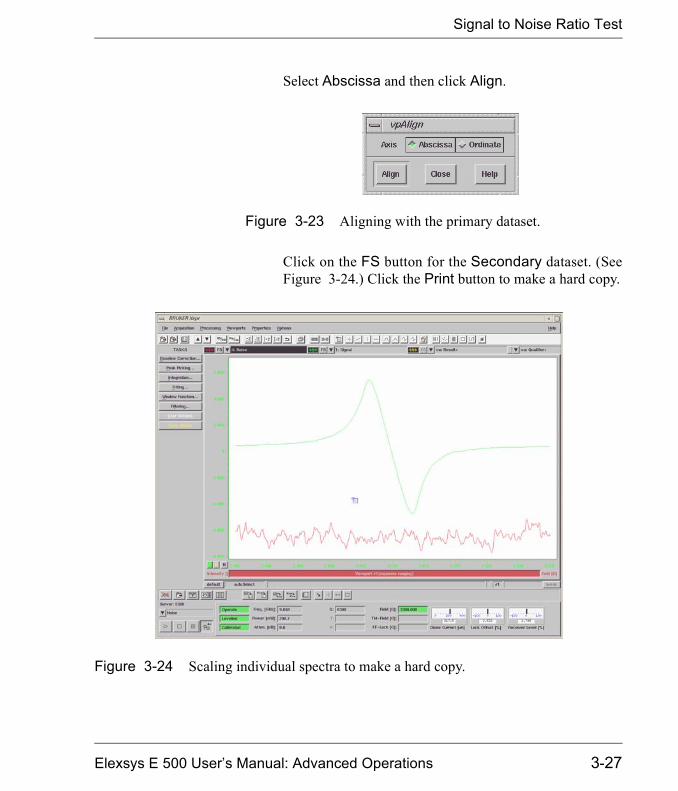
Signal to Noise Ratio Test
Select Abscissa and then click Align.
Click on the FS button for the Secondary dataset. (SeeFigure 3-24.) Click the Print button to make a hard copy.
Figure 3-23 Aligning with the primary dataset.
Figure 3-24 Scaling individual spectra to make a hard copy.
Elexsys E 500 User�s Manual: Advanced Operations 3-27

Signal to Noise Ratio Test
Signal to Noise Ratio Test for an ER 4102ST Cavity 3.1.5The parameters and the specifications for the ER 4102ST cavityare different from those for the ER 4122SHQ cavity. The mea-surement procedure however is identical. Perform the operationsof the previous section except with the following parameters.
The signal to noise ration should be at least 360.
Parameter Signal Measurement
Noise Measurement
ModulationAmplitude
6.0 G 6.0 G
ModulationFrequency
100 kHz 100 kHz
Receiver Gain 60-70 dB 80 dB
Phase 0 0
Time Constant 1310.72 ms 1310.72 ms
Conversion Time 163.84 ms 163.84 ms
Center Field 3480 G 1500 G
X Axis Setting Field Sweep Time Scan
Sweep Width 50 G --
Resolutionof X Axis
1024 points 1024 points
MicrowaveAttenuation
12 dB 0 dB
Table 3-2 Parameters for Signal/Noise Measurements for an ER 4102ST cavity.
3-28
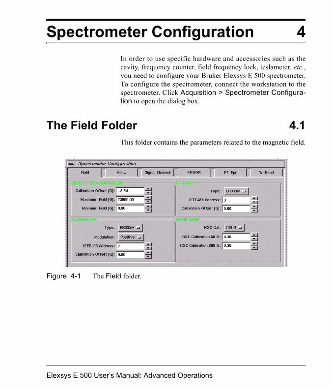
Spectrometer Configuration 4In order to use specific hardware and accessories such as thecavity, frequency counter, field frequency lock, teslameter, etc.,you need to configure your Bruker Elexsys E 500 spectrometer.To configure the spectrometer, connect the workstation to thespectrometer. Click Acquisition > Spectrometer Configura-tion to open the dialog box.
The Field Folder 4.1This folder contains the parameters related to the magnetic field.
Figure 4-1 The Field folder.
Elexsys E 500 User�s Manual: Advanced Operations
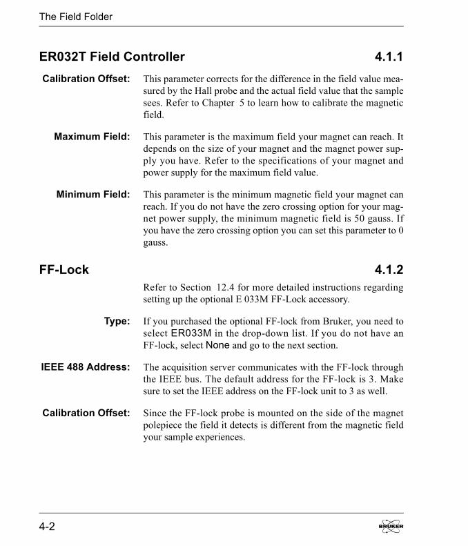
The Field Folder
ER032T Field Controller 4.1.1Calibration Offset: This parameter corrects for the difference in the field value mea-
sured by the Hall probe and the actual field value that the samplesees. Refer to Chapter 5 to learn how to calibrate the magneticfield.
Maximum Field: This parameter is the maximum field your magnet can reach. Itdepends on the size of your magnet and the magnet power sup-ply you have. Refer to the specifications of your magnet andpower supply for the maximum field value.
Minimum Field: This parameter is the minimum magnetic field your magnet canreach. If you do not have the zero crossing option for your mag-net power supply, the minimum magnetic field is 50 gauss. Ifyou have the zero crossing option you can set this parameter to 0gauss.
FF-Lock 4.1.2Refer to Section 12.4 for more detailed instructions regardingsetting up the optional E 033M FF-Lock accessory.
Type: If you purchased the optional FF-lock from Bruker, you need toselect ER033M in the drop-down list. If you do not have anFF-lock, select None and go to the next section.
IEEE 488 Address: The acquisition server communicates with the FF-lock throughthe IEEE bus. The default address for the FF-lock is 3. Makesure to set the IEEE address on the FF-lock unit to 3 as well.
Calibration Offset: Since the FF-lock probe is mounted on the side of the magnetpolepiece the field it detects is different from the magnetic fieldyour sample experiences.
4-2
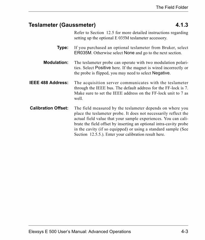
The Field Folder
Teslameter (Gaussmeter) 4.1.3Refer to Section 12.5 for more detailed instructions regardingsetting up the optional E 035M teslameter accessory.
Type: If you purchased an optional teslameter from Bruker, selectER035M. Otherwise select None and go to the next section.
Modulation: The teslameter probe can operate with two modulation polari-ties. Select Positive here. If the magnet is wired incorrectly orthe probe is flipped, you may need to select Negative.
IEEE 488 Address: The acquisition server communicates with the teslameterthrough the IEEE bus. The default address for the FF-lock is 7.Make sure to set the IEEE address on the FF-lock unit to 7 aswell.
Calibration Offset: The field measured by the teslameter depends on where youplace the teslameter probe. It does not necessarily reflect theactual field value that your sample experiences. You can cali-brate the field offset by inserting an optional intra-cavity probein the cavity (if so equipped) or using a standard sample (SeeSection 12.5.5.). Enter your calibration result here.
Elexsys E 500 User�s Manual: Advanced Operations 4-3

The Field Folder
Rapid Scan 4.1.4Refer to Section 6.4 for more detailed instructions regardingsetting up rapid scan experiments.
RSC Coil: When performing rapid scan experiments, you need to select oneset of rapid scan coils. If you use the scan coils mounted on themagnet, select 200 G. If you use the scan coils assembled in thecavity, select 50 G.
RSC Calibration50 G:
The sweep width of the rapid scan coils needs to be calibrated.Enter the calibration factor for the 50 G rapid scan coils here.Refer to Section 6.4 to learn how to calibrate the sweep width ofthe rapid scan coils.
RSC Calibration200 G:
Enter the calibration factor of the 200 G rapid scan coils here.Refer to Section 6.4 to learn how to calibrate the sweep width ofthe rapid scan coils.
4-4

The Misc. Folder
The Misc. Folder 4.2The Misc. (miscellaneous) folder of the Spectrometer Config-uration dialog box contains configuration parameters for a vari-ety of hardware components and accessories.
Microwave Band 4.2.1Microwave Band: Depending on the microwave bridge you are using you can
select from L-, S-. X-, K-, Q- or W-band.
AutotuneAttenuation:
This value sets the microwave power for the autotuning process.For a standard cavity, set it to 25 dB. For a resonator with a veryhigh Q value you can set it to 30 dB or higher. Setting the Atten-uation too low or too high may cause the autotuning process tofail.
Figure 4-2 The Microwave Band section of the Misc. folder.
Elexsys E 500 User�s Manual: Advanced Operations 4-5

The Misc. Folder
Microwave Frequency Counter 4.2.2See Section 12.1 for details on setting up frequency counters.
Type: If you do not have a frequency counter, select MBC. The MBC(Microwave Bridge Controller) board provides an approximate(three digits) microwave frequency. You can use an accurate fre-quency counter to calibrate the microwave frequency and enterthe calibration result into the MBC Calibration Offset. If youneed a more accurate microwave frequency reading, use eitherthe Bruker frequency counter or another frequency counter pro-vided by other vendors. For the Bruker frequency counter, selectBruker in the drop-down list. For other frequency counters youcan select one that Xepr supports.
IEEE 488 Address: If you are using the frequency counters from vendors other thanBruker, you need to set the IEEE 488 address to 8. For theBruker and MBC options, you do not need to set the IEEEaddress.
MBC CalibrationOffset:
This offset is for MBC board calibration only. Use a frequencycounter to calibrate the difference between the frequencycounter and the MBC board and enter the result here. SeeSection 12.1.1 for instructions on how to measure the offset.
4-6
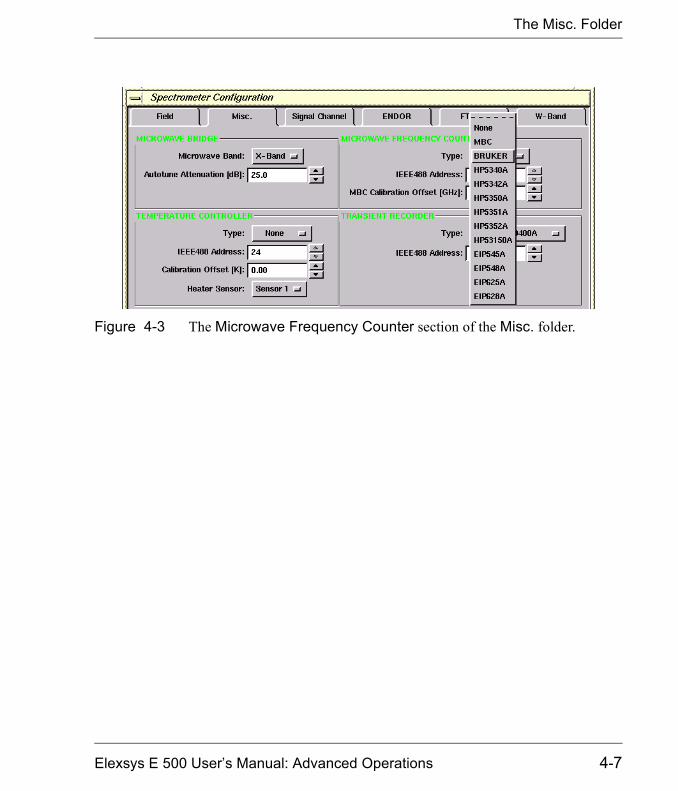
The Misc. Folder
Figure 4-3 The Microwave Frequency Counter section of the Misc. folder.
Elexsys E 500 User�s Manual: Advanced Operations 4-7

The Misc. Folder
Temperature Controller 4.2.3Refer to Section 12.2 and Section 12.3 for more details on set-ting up and using temperature controllers.
Type: The Bruker Elexsys spectrometer supports two types of tempera-ture controllers. ER 4111VT, ER 4121VT, and ER 4131VTvariable temperature systems use liquid nitrogen whereas theITC 5 system uses liquid helium. Select the temperature control-ler you wish to use. Refer to Section 12.2 for further details.
IEEE 488 Address: The acquisition server communicates with the ITC5 temperaturecontroller through the IEEE bus. The default address for theITC5 is 24. Make sure to set the IEEE address on the ITC5 tem-perature controller to 24 as well. The other controllers do not usethe IEEE bus and the value does not affect their operation.
Calibration Offset: Because the sample and thermocouple are not in the same posi-tion, the temperature measured by the thermocouple may differfrom the actual sample temperature. You can use a temperature
Figure 4-4 The Temperature Controller section of the Misc. folder.
4-8

The Misc. Folder
sensor to calibrate the actual sample temperature and enter thedifference here. Refer to Section 12.2 Section 12.3 for details.
Heater Sensor: For the ITC temperature controller, there are several sensorinputs that can be used to control the heater. Refer to the temper-ature controller�s manual to find out which sensor to use andselect the correct sensor. The value does not affect the operationof the other temperature controllers.
Transient Recorder 4.2.4
Type: Xepr supports several models of optional transient recorders. Ifyou are using a transient recorder that is listed in the drop-downlist, select it.
IEEE 488 Address: The acquisition server communicates with the transient recorderthrough the IEEE bus. The default address is 9. Make sure to setthe IEEE address on the transient recorder to 9 as well.
Figure 4-5 The Transient Recorder section of the Misc. folder.
Elexsys E 500 User�s Manual: Advanced Operations 4-9
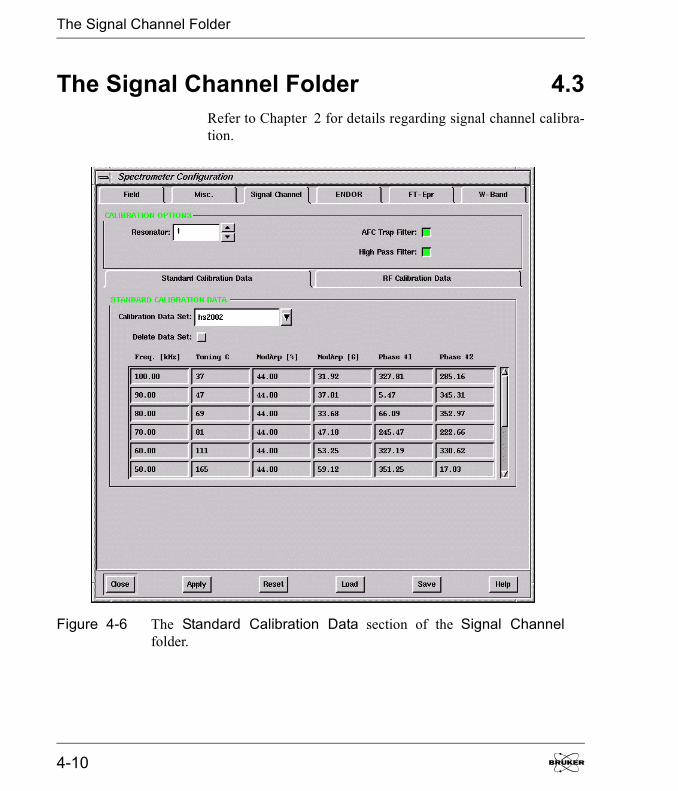
The Signal Channel Folder
The Signal Channel Folder 4.3Refer to Chapter 2 for details regarding signal channel calibra-tion.
Figure 4-6 The Standard Calibration Data section of the Signal Channelfolder.
4-10
Other Folders
Calibration Options 4.3.1Resonator The ER 4105DR resonator has two sets of modulation coils.
Selecting 1 or 2 displays the calibration values for theResonator1 or 2 channel of the modulation amplifier module.
Standard Calibration Data 4.3.2Calibration Data
Set:Every resonator needs signal channel calibration data for repro-ducible and quantitative results. The calibration data is stored ina file on the disk. Select the correct file for the resonator you areusing. Each file contains information such as the modulationamplitude and phase calibration as well as modulation amplitudelimits and tuning capacitor values.
RF Calibration Data. 4.3.3This subfolder contains signal channel calibration data for theRF used in ENDOR experiments. Refer to the ENDOR docu-mentation for further details.
Other Folders 4.4There are other folders in the Spectrometer Configuration dia-log box. They are for ENDOR, FT-EPR, and W-Band. Refer totheir respective user�s manuals for further information.
Elexsys E 500 User�s Manual: Advanced Operations 4-11

Notes
4-12
Field Offset & g-Factor 5Because the sample and Hall probe are not physically in thesame location in the magnet, the Hall probe measures a magneticfield different from that experienced by the sample. This fielddifference is often called the field offset. Carefully measuringthe magnetic field offset is critical for precisely measuring g-val-ues and other EPR parameters. There are several methods to cal-ibrate the magnetic field. The most direct way of calibrating themagnetic field is to measure the magnetic field at the sampleusing a teslameter (or gaussmeter) with an intra-cavity probewhich you can place in the sample position and then comparethat value with the field value that the Hall probe detects. Alter-natively, if you do not have a teslameter available you can use afrequency counter and a sample with known g-value. Thismethod is described in this chapter. You can also use this methodto measure the g-value of your sample.
Field Calibration Standards 5.1A standard sample with an accurately measured g-value, whichis used to mark the field value, is called a field calibration stan-dard. It is also called a g-marker. The criteria for selecting such astandard sample are:
1. The g-factor has been accurately measured.
2. The EPR signal is isotropic and symmetric with goodreproducibility.
3. The EPR signal has a relatively narrow line width. Thenarrower the line width, the more accurately the magneticfield or g-value can be determined.
4. The EPR signal is strong enough to avoid noise inducederrors.
Elexsys E 500 User�s Manual: Advanced Operations
Measuring the Field Offset
5. The sample is relatively stable.
Examples of such standard samples are potassium peroxylaminedisulfonate (K2(SO3)NO (known as Fremy�s salt or PADS) in a10% Na2CO3 degassed aqueous solution and a dilute perylenesolution in degassed concentrated H2SO4. In this chapter we useperylene radical cation as the standard sample. The g-factor hasbeen reported to be 2.002569 ± 0.000006. (B. G. Segal, M.Kaplan, and G. K. Fraenkel, J. Chem. Phys., 43, 4191 (1965);R. D. Allendoerfer, J. Chem. Phys., 55, 3615 (1971))
Measuring the Field Offset 5.2
Calibrating the Field Offset 5.2.11. Insert the sample and tune the system. 2. Set the Field Offset to zero. Click Acquisition >
Spectrometer Configuration > Field and enter 0 in theField Offset box. Click Apply and Close.
3. Create a field sweep experiment.4. Set appropriate parameters for your sample.
Figure 5-1 shows a parameter set that works well for aperylene sample. The microwave power is set at 0.05 mWfor the perylene sample to avoid line broadening due tomicrowave saturation. The number of data points is set at4096.
5-2
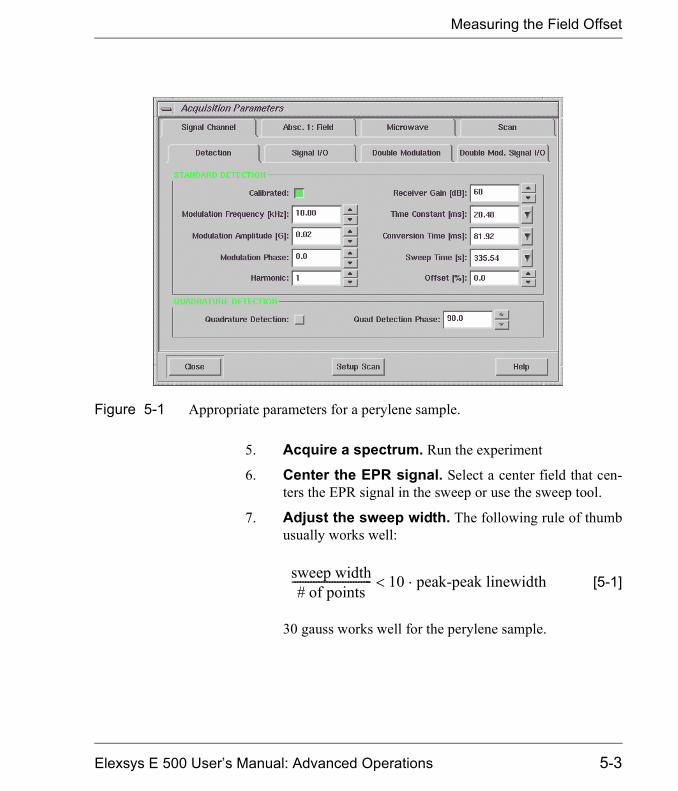
Measuring the Field Offset
5. Acquire a spectrum. Run the experiment
6. Center the EPR signal. Select a center field that cen-ters the EPR signal in the sweep or use the sweep tool.
7. Adjust the sweep width. The following rule of thumbusually works well:
[5-1]
30 gauss works well for the perylene sample.
Figure 5-1 Appropriate parameters for a perylene sample.
sweep width# of points
------------------------------ 10 peak-peak linewidth��
Elexsys E 500 User�s Manual: Advanced Operations 5-3

Measuring the Field Offset
8. Measure the magnetic field for the center line.Zoom in on the center EPR line and move the cursor tothe zero cross over point of the center EPR line. Read thefield value, B0, from the Viewport Selection bar.
9. Determine the field value for the known g factor.Move the cursor until the g-factor reading from the View-port Selection bar matches the known sample g-factor.Read the magnetic field value, B0�, of that point.
Figure 5-2 Zooming in to measure the center EPR line field value.
Move theCursor
Read theField Value
5-4
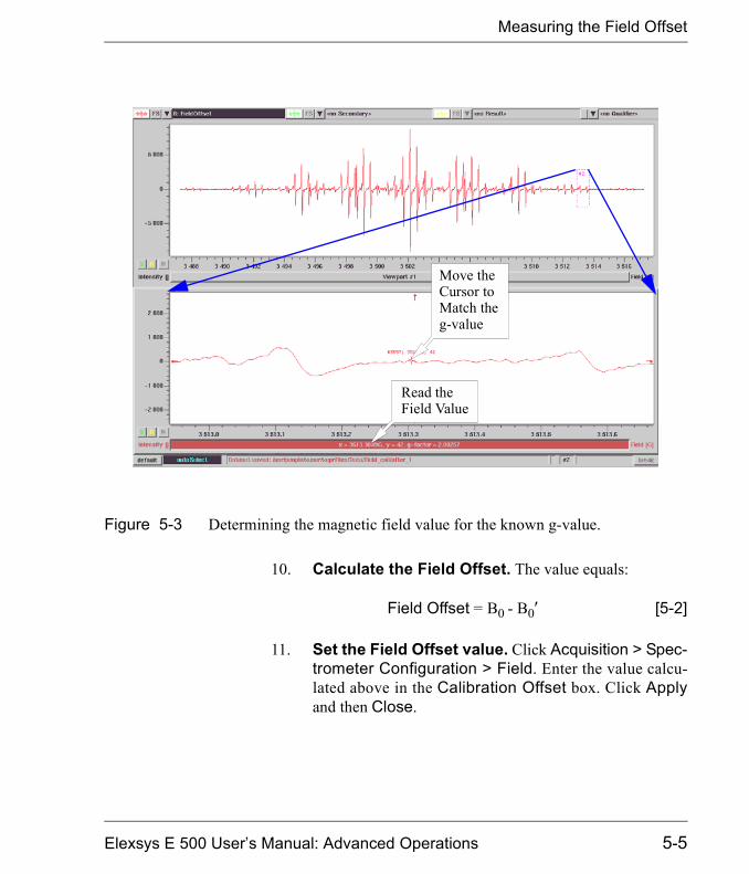
Measuring the Field Offset
10. Calculate the Field Offset. The value equals:
Field Offset =�B0 - B0� [5-2]
11. Set the Field Offset value. Click Acquisition > Spec-trometer Configuration > Field. Enter the value calcu-lated above in the Calibration Offset box. Click Applyand then Close.
Figure 5-3 Determining the magnetic field value for the known g-value.
Move theCursor toMatch theg-value
Read theField Value
Elexsys E 500 User�s Manual: Advanced Operations 5-5
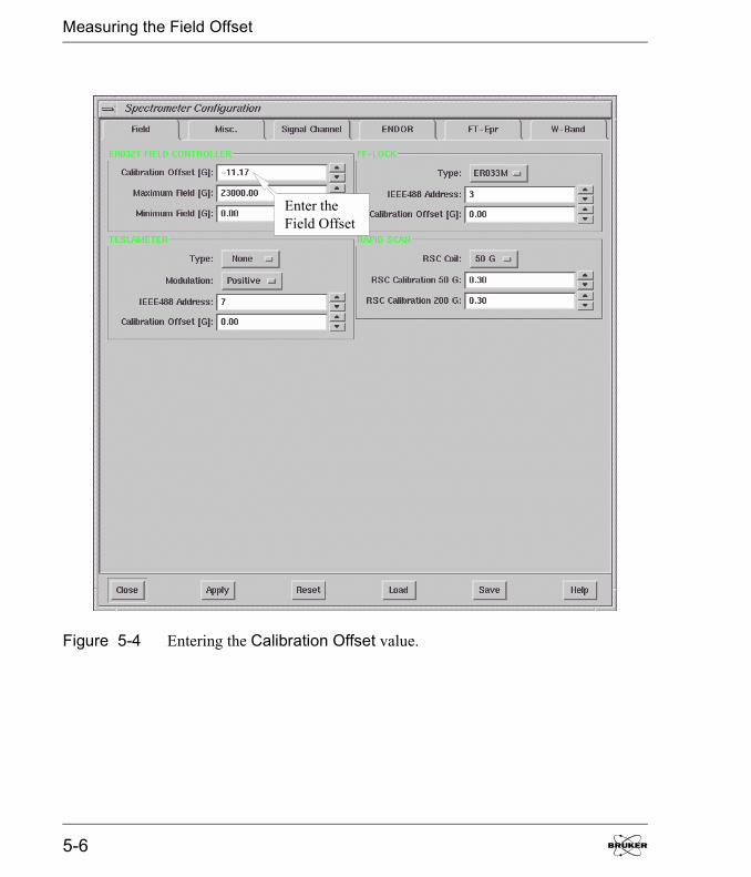
Measuring the Field Offset
Figure 5-4 Entering the Calibration Offset value.
Enter theField Offset
5-6
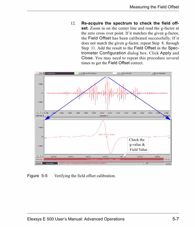
Measuring the Field Offset
12. Re-acquire the spectrum to check the field off-set. Zoom in on the center line and read the g-factor atthe zero cross over point. If it matches the given g-factor,the Field Offset has been calibrated successfully. If itdoes not match the given g-factor, repeat Step 8. throughStep 11. Add the result to the Field Offset in the Spec-trometer Configuration dialog box. Click Apply andClose. You may need to repeat this procedure severaltimes to get the Field Offset correct.
Figure 5-5 Verifying the field offset calibration.
Check the
Field Valueg-value &
Elexsys E 500 User�s Manual: Advanced Operations 5-7
Measuring the Field Offset
Tips for Measuring the Field Offset 5.2.2� Thermal equilibrium. The Hall voltage used for field reg-
ulation has a temperature coefficient. This effect is compen-sated by use of a thermostat to control the Hall probetemperature. Very good performance is achieved after aboutone hour after turning the spectrometer on. Optimal stabilityis attained after 72 hours. Wait until the spectrometer iswarmed up
� Magnet hysteresis. Magnet hysteresis affects the accu-racy of the field values. You may need to saturate the mag-nets by setting the magnetic field to ~ 12,000 gauss for aboutone minute before you start measurements. Saturating themagnet first will reduce the hysteresis.
� Select the proper number of data points. You mayneed to select 4096 data points to read the field value pre-cisely. Depending on the sweep width and the line width,more data points usually give you more accuracy. When youare close to the correct field you may need to use narrowersweep width. If the signal is strong you may acquire the sec-ond harmonic spectrum to precisely locate the field of thecenter EPR line.
� Scan slowly. If you sweep the field too fast the magnet maynot be able to follow. Set the sweep time long enough toavoid any distortion.
� Avoid saturating the sample. Too much microwavepower not only saturates the sample and causes distortion andbroadening of the EPR signal, but also may heat up the sam-ple. The g-value of the sample may be temperature depen-dent, resulting in an inaccurate calibration. Frequently theEPR absorption signal becomes more dispersive under powersaturation, which makes determination of the zero cross overpoint more difficult and less accurate.
Saturating the magnetonly applies to 8� orlarger magnet with a7 kW or greater powersupply. For p recisemeasurements of g-val-ues and calibration ofthe field offset, an 8� orlarger magnet and cor-responding power sup-ply is recommended.
5-8

g-Value Measurements
� Do not over-modulate the signal. Over-modulationcauses signal distortion which can also affect the accuracy ofthe field offset measurement.
� How often do I need to calibrate the field offset? Itdepends on how precisely you need to know the actual fieldvalues. You may need to calibrate the field offset every timeyou change the cavity or move the bridge if you need to mea-sure your g-values more precisely than 4 figures after thedecimal point.
g-Value Measurements 5.3To precisely determine the g-factor you need to know two val-ues: the magnetic field and the microwave frequency. Then youcan calculate the g-value based on the formula:
, [5-3]
where h is Planck�s constant, �� is the Bohr magneton, � is themicrowave frequency in GHz and B0 is the magnetic field ingauss. Alternatively:
. [5-4]
The precision of the g-factor measurement depends on how pre-cisely you can determine the microwave frequency and the mag-netic field. If you are using a microwave frequency counter, themagnetic field uncertainty determines the precision.
Precise g-value measurement requires some care. The tips listedin Section 5.2.2 also hold true for g-value measurements. Con-
g h��BB0-------------=
g 714.4775 �
B0------�=
A m icr o wa ve f r e -q ue n c y co u n t e r i sessential to measure theg-value to a precisionany greater than twodigits after the decimalpoint.
Elexsys E 500 User�s Manual: Advanced Operations 5-9
g-Value Measurements
tributions to field measurement uncertainties are not necessarilydue to instrumental factors. Such factors as line shape, linewidth, solvent effects, isotropic or anisotropic interactions, sen-sitivity to concentration, etc. must be considered.
If you are using the Hall field controller for field measurement,you can measure g-values to 100 ppm if you have carefullydetermined the field offset, followed the hints (as described inthe previous section), and you have a sufficiently narrow EPRline (< 0.1 G). For more precise g-value determinations, youmust use a teslameter. If you have followed the advice of theprevious section, have carefully calibrated the teslameter offset,and have a sufficiently narrower line (<0.1 G) you can measureg-values sometimes down to 100 ppb precision. ConsultSection 12.5 for details on teslameter operation.
Xepr can automatically provide the g-factor based on the fre-quency and field value it has measured. You only need to placethe mouse pointer to where you want to know the g-factor andthe g-value will be displayed in the selection bar of the viewport.(See Figure 5-2.) Xepr even has a function that can convert thefield domain to the g-domain (Processing > Transformation >g-factor).
These methods, can also be used to interpret hyperfine couplingconstants and zero field splittings.
5-10
The Fast Digitizer & Rapid Scans 6Many physical and chemical processes occur on time-scales tooshort for the magnet and the digitizer in the signal channel to fol-low them. In order to expand the capabilities of the spectrometerto shorter time-scales, the spectrometer is equipped with a fastdigitizer and a set of rapid scan coils.
Rapid Time Scan Experiments 6.1This section describes the use of the fast digitizer for acquiringfast time scans at a constant magnetic field value.
The Fast Digitizer 6.1.1The ADF board is a fast, two channel digitizer board capable ofdigitizing at a 2 MHz rate. The first channel (Channel A) isreserved for digitizing EPR signals. The second channel may beused to digitize other signals, such as the output of a photomulti-plier tube. The fast digitizer can capture data more quickly thanthe integrating ADC (Analog to Digital Converter) of the signalchannel. It has a fixed 12 bit resolution and therefore yields bet-ter y-resolution than the signal channel digitizer when the con-version time is less than 2.56 ms.
The digitizer acquires data at a fixed 2 Msamples/s rate. In orderto change the sweep time for an experiment, the number of dataaccumulations for a specific field or time value is increased ordecreased. The fast digitizer contains an on-board accumulatorwhich accumulates several data values (y-value) at each time orfield step (x-value). The number of accumulations is set by thesoftware to make maximum use of the selected sweep time.
Elexsys E 500 User�s Manual: Advanced Operations

Rapid Time Scan Experiments
Performing a Rapid Time Scan Experiment 6.1.2Before you start, you should have already turned the spectrome-ter on, inserted your sample, and tuned the spectrometer. Consultthe Elexsys E 500 User�s Manual: Basic Operations for furtherdetails regarding ordinary time scan experiments because bothtypes of experiments share many common operations andparameters.
1. Create a time scan experiment using the fast dig-itizer. Click New Experiment and select the CW sub-folder. In the Abscissa 1 drop-down list, select Time.Select Fast digitizer in the Ordinate drop-down list.Click Create to close the dialog box. (See Figure 6-1.)
Figure 6-1 Creating a time scan experiment.
6-2

Rapid Time Scan Experiments
2. Click the Acquisition Parameters button to openthe Acquisition Parameters dialog box.
3. Set common EPR parameters. Set the microwavepower, modulation amplitude, and receiver gain to appro-priate values.
4. Set the Static Field. Set the Static Field in the Fieldfolder so that it coincides with the top of your EPR signal.
Figure 6-2 The Fast Digitizer subfolder.
Elexsys E 500 User�s Manual: Advanced Operations 6-3

Rapid Time Scan Experiments
5. Set Auto Offset to Off in the Scan folder. In a timescan experiment, you are usually interested in the initialand final intensities and this information is lost if AutoOffset is set to On.
6. Set the Sweep Time. Change either the Sweep Timeor Accumulations per Point in the Fast Digitizer folder.When you change one parameter, the other automaticallyupdates to the proper value.
7. Set an appropriate time constant. Because this classof experiments is measuring rapidly changing signals, youmust insure your time constant is low enough that it doesnot distort the acquired signal. A good rule of thumb ifyou have a strong signal is:
Time Constant = Number of Accumulations * 500 ns / 4. [6-1]
If your signal is weak, you may need to compromise andincrease the time constant.
8. Run the experiment. Click the Run button to acquirethe time scan.
6-4
Rapid Time Scan Experiments
Fast Digitizer Parameters 6.1.3Refer to Figure 6-2 to identify the various Fast Digitizerparameters.
Sweep Time As was mentioned previously, a number of parameters deter-mine the Sweep Time. In Internal Sweep mode:
Sweep Time = Accumulations per Point [6-2]* Number of points * 500 ns.
The maximum Sweep Time is 134 seconds (with the defaultoptions) corresponding to 65535 maximum Accumulations perPoint.
Accumulationsper Point
This parameter determines the time resolution and consequentlythe Sweep Time in Internal Sweep mode.
Time Resolution = Accumulations per Point * 500 ns. [6-3]
The minimum Accumulations per Point is 1 and the maximumvalue is 65535.
Trigger Mode There are four different Trigger Modes. Internal Sweep is thedefault mode in which the internal clock triggers the beginningof the sweep. Equation [6-2] relates the Accumulations perPoint and Sweep Time. In this mode, if one parameter ischanged, the other is automatically updated to fulfill Equation[6-2].
Elexsys E 500 User�s Manual: Advanced Operations 6-5
Rapid Time Scan Experiments
The second mode is Internal Point mode in which each point istriggered by the internal clock. In this mode, the Accumula-tions per Point becomes more independent than in the firstmode. The Sweep Time is specified (< 134 seconds) and theAccumulations per Point can be set to values:
1��� Accumulations per Point��� [6-4]Sweep Time / Number of Points * 500 ns.
There are two analogous modes, External Sweep and ExternalPoint in which the experiments are synchronized to an externaltrigger as opposed to the internal clock. The external signal isapplied to the cable labeled Ext. Trigger that is connected to theAUX connector of the ADF board. (See Section 14.2.3.)
Trigger Slope If you have selected one of the external trigger modes, you canselect whether the Falling or Rising edge of the external triggerpulse triggers the acquisition.
Input Mode There are two Fast Digitizer input channels. Channel A isreserved for EPR signals, but channel B is available for othersignals such as the output of a photomultiplier tube, etc. Youhave the option of choosing to record channel A, B, or bothA & B simultaneously in this drop-down list.
6-6

The Rapid Field Scan Experiment
The Rapid Field Scan Experiment 6.2To sweep the magnetic field rapidly we need to employ a specialdevice called the Rapid Scan Controller (RSC). It has a pro-grammable ramp generator which is used to set the shape of thefield sweep. It generates very fast field sweep cycles to matchthe speed of the ADF board. The center field of the rapid fieldscans is centered about the static field supplied by the main mag-net.
The field sweep cycle is applied to the rapid scan coils. Thecycle consists of three distinct regimes. (See Figure 6-3.) Theacquis i t ion occurs dur ing the Ramp-up per iod. TheRamp-down and Delay times are necessary to return to the ini-tial magnetic field value.
Since the inductance of the rapid scan coils is much lower thanthat of the electromagnet, the field can be swept much faster.There are two rapid scan coils. The internal rapid scan coils arebuilt in some of the Bruker cavities. The external rapid scancoils are mounted on the magnet pole caps. The maximum rapidscan sweep widths are 50 G for internal rapid scan coils and 200G for external rapid scan coils respectively. You can select therapid scan coils and adjust the calibration factors of the sweepwidth in the configuration menu.
Figure 6-3 The rapid field sweep cycle.
t
B0
Ramp
Up
Ram
pD
own
Delay
Elexsys E 500 User�s Manual: Advanced Operations 6-7

The Rapid Field Scan Experiment
Configuring the Rapid Scan Experiment 6.2.1The ADF board should be already connected when the spec-trometer is delivered. You may need to connect the rapid scancoil and configure the Xepr program.
1. Connect the Rapid Scan Coils. As mentioned before,there are two rapid scan coils; the 200 G rapid scan coilsthat are mounted to the pole caps of the magnet and the 50G rapid scan coils that are built in some Bruker cavitiessuch as the standard cavity ER 4102ST. Connect theorange cable from the Modulation Amplifier RS 200 Gconnector in the console to the connector of the 200 Grapid scan coils on the magnet. Connect the yellow cablefrom the Modulation Amplifier RS 50 G connector tothe left connector (labeled R.S.) of the Bruker cavity.
2. Configure the spectrometer. Turn on the spectrome-ter and connect the workstation to the spectrometer. SelectAcquisition > Spectrometer Configurations. Clickingthe Field tab, you can find the Rapid Scan section. Inthis section, select 50 G or 200 G as the rapid scan coils(RSC) depending upon which rapid scan coil you want touse. Click Apply. Underneath, there are calibration factorsof the rapid scan width for 50 G and 200 G coils respec-tively. We will discuss this calibration in Section 6.4.
Not all Bruker cavitiesare equipped with 50 Grapid scan coils. If thecavity you are usingdoes not have an R.S.connector, you canonly use 200 G rapidscan coils.
6-8
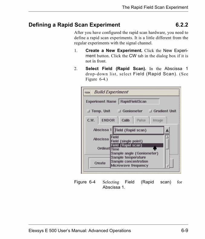
The Rapid Field Scan Experiment
Defining a Rapid Scan Experiment 6.2.2After you have configured the rapid scan hardware, you need todefine a rapid scan experiments. It is a little different from theregular experiments with the signal channel.
1. Create a New Experiment. Click the New Experi-ment button. Click the CW tab in the dialog box if it isnot in front.
2. Select Field (Rapid Scan). In the Abscissa 1drop-down list, select Field (Rapid Scan) . (SeeFigure 6-4.)
Figure 6-4 Selecting Field (Rapid scan) forAbscissa 1.
Elexsys E 500 User�s Manual: Advanced Operations 6-9
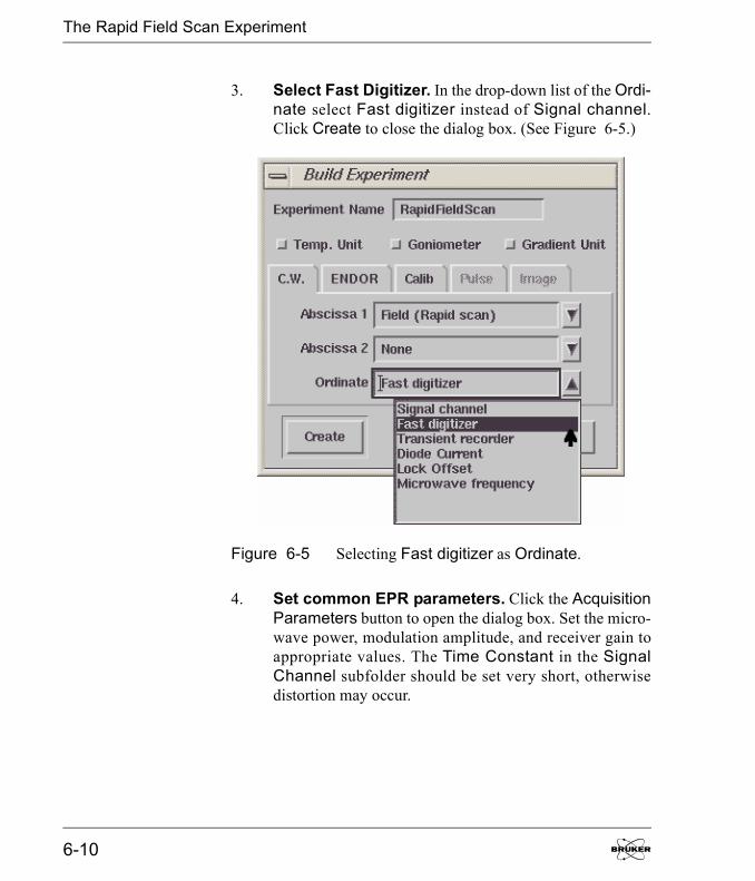
The Rapid Field Scan Experiment
3. Select Fast Digitizer. In the drop-down list of the Ordi-nate select Fast digitizer instead of Signal channel.Click Create to close the dialog box. (See Figure 6-5.)
4. Set common EPR parameters. Click the AcquisitionParameters button to open the dialog box. Set the micro-wave power, modulation amplitude, and receiver gain toappropriate values. The Time Constant in the SignalChannel subfolder should be set very short, otherwisedistortion may occur.
Figure 6-5 Selecting Fast digitizer as Ordinate.
6-10

The Rapid Field Scan Experiment
5. Set Sweep Quantity: Field parameters. In theAbscissa 1 Sweep Quantity: Field section enter theCenter Field value for your experiment. Enter the desiredSweep width. The maximum sweep width depends onthe rapid scan coils you are using and selected in the Sys-tem Configuration folder. By default the Number ofPoints is set at 4096 which gives you a reasonable resolu-tion in most cases. We shall keep the Center Field Offsetvalue at zero for now. (See Section 6.4 for details on theCenter Field Offset parameter.)
Figure 6-6 Parameters for rapid field scans.
Elexsys E 500 User�s Manual: Advanced Operations 6-11

The Rapid Field Scan Experiment
6. Set the RSC Trigger and Input Mode parameters.Select Internal as the RSC Trigger Mode. Select A asInput Mode. Channel A is reserved for EPR signals.
7. Select an appropriate Sweep Ramp-up Time.Since the minimum signal channel time constant is 0.01ms, you need to set the Sweep Ramp-up Time longenough so that the time sweeping through the upper peakand the lower peak of an EPR line is at least 0.1 ms (or 10times the Time Constant) to avoid distortion.
8. Set the Sweep Ramp-down Time. The SweepRamp-down Time is the time for the field to fly back.The optimal Sweep Ramp-down time depends on yourexperiment and other settings. The best way to set an opti-mal Sweep Ramp-down Time is lengthen it until thereare no flyback glitches appearing in your spectrum.
9. Set the Sweep Delay Time. If you set the scan numberto more than 1 in the Scan subfolder you need to set aproper Sweep Delay Time so that the field can settleafter fly-back. The optimal Sweep Delay Time dependson your experiment and other settings. The best way to setan optimal Sweep Delay Time is lengthen it until thereare no flyback glitches appearing in your spectrum.
10. Run the experiment. Click the Run button to acquirethe time scan.
The Sweep Ramp-upTime , Number o fPoints, and the Accu-mulations per Pointare related. More datapoints usually providebetter resolution butlonger sweep time orless Accumulationsper Point. You need toba l ance t hese t h reeparameters to achievethe acceptable distor-tion, resolution, andacquisition time.
6-12
The Rapid Field Scan Experiment
Rapid Scan Parameters 6.2.3Refer to Figure 6-6 to identify the various Fast Digitizerparameters.
Center Field The static field about which the magnetic field is rapidly swept.
Sweep Width The width of the rapid scan magnetic field sweep. It has a maxi-mum value of 50 G for the 50 G rapid scan coils and 200 G forthe 200 G rapid scan coils.
Center Field Offset There is a Center Field Offset in order to compensate for thefield hysteresis caused by the rapid scan. (See Section 6.4.)
Number of Points The number of points acquired during the rapid scan experiment.
Input Mode There are two Fast Digitizer input channels. Channel A isreserved for EPR signals, but channel B is available for othersignals such as the output of a photomultiplier tube, etc. Youhave the option of choosing to record channel A, B, or bothA & B simultaneously in this drop-down list.
RSC Trigger Mode The acquisition can be triggered in Internal mode in whichpressing the Run button initiates the acquisition. You may alsoselect to trigger the acquisition in External mode with an exter-nal trigger. (See Section 14.2.4.)
Elexsys E 500 User�s Manual: Advanced Operations 6-13
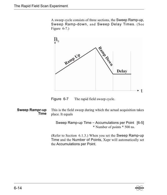
The Rapid Field Scan Experiment
A sweep cycle consists of three sections, the Sweep Ramp-up,Sweep Ramp-down, and Sweep Delay Times . (SeeFigure 6-7.)
Sweep Rampr-upTime
This is the field sweep during which the actual acquisition takesplace. It equals
Sweep Ramp-up Time = Accumulations per Point [6-5]* Number of points * 500 ns.
(Refer to Section 6.1.3.) When you set the Sweep Ramp-upTime and the Number of Points, Xepr will automatically setthe Accumulations per Point.
Figure 6-7 The rapid field sweep cycle.
t
B0
Ramp Up
Ram
pD
own
Delay
6-14
The Rapid Field Scan Experiment
SweepRamp-down
Time
This is the �fly-back� time during which the field returns to itsstarting position. No acquisition is done. It is part of the deadtime. If this parameter is set too low, the field is not yet fullyback to its starting value when the next acquisition begins andgenerates glitches caused by the fly-back trace in the next spec-trum. The minimum Ramp-down time is 0.1 ms.
DelayTime
After the ramp down time, there is a delay time during which thesystem can recover from overshoots after the fly-back. This isalso part of the dead-time. This is the time delay between suc-cessive sweeps when using multiple sweeps. Depending on thesweep width, a sufficiently long delay time is needed to avoidglitches and distortion. The minimum Delay time is 0.1 ms. Ifthe Overload LED on the Field Controller turns red it is anindication that the Sweep Delay Time is too short.
RepetitionFrequency
The sweep Repetition Frequency is the reciprocal of the sumof Ramp-up, Ramp-down, and Delay times. It indicates therate of successive sweeps when multiple scans are acquired.
Accumulations perPoint
The value of the Accumulations per Point will be set automat-ically in accordance with Equation [6-5] when you set theSweep Ramp-up Time. However, you can also set the Accu-mulations per Point. If you do so the Sweep Ramp-up Timewill be adjusted automatically by the software. It is analogous toAccumulations per Point described in Section 6.1.3.
Elexsys E 500 User�s Manual: Advanced Operations 6-15
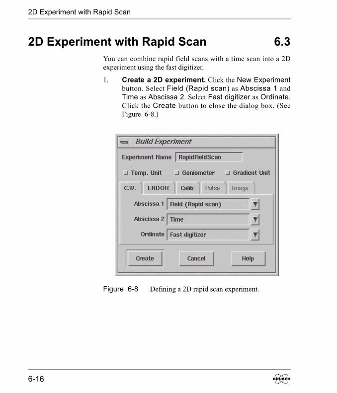
2D Experiment with Rapid Scan
2D Experiment with Rapid Scan 6.3You can combine rapid field scans with a time scan into a 2Dexperiment using the fast digitizer.
1. Create a 2D experiment. Click the New Experimentbutton. Select Field (Rapid scan) as Abscissa 1 andTime as Abscissa 2. Select Fast digitizer as Ordinate.Click the Create button to close the dialog box. (SeeFigure 6-8.)
Figure 6-8 Defining a 2D rapid scan experiment.
6-16

2D Experiment with Rapid Scan
2. Select parameters for rapid field scan. Click theAcquisition Parameters button to open the dialog box.Set the parameters in the Absc.1 Field the same way asfor the Rapid Field Scan experiment described inSection 6.2.2.
3. Set parameters for Absc. 2: Delay. Click theAbsc. 2: Delay tab. Set the Delay time in ms betweenrapid field scans. Although you can set the Delay time to0, the minimum delay time is the minimum time neces-sary for communication and data transfer. The DelaySince Acq. Starts displays the overall time since theacquisition starts. Each slice will be labeled by the timewhen the acquisition of this slice starts. You need tochoose the number of data points or slices on the Y-axisand enter this value into the Number of Points. (SeeFigure 6-9.)
4. Run the experiment. Click the Run button to acquirethe 2D experiment.
Figure 6-9 Parameters for Absc. 2 Delay.
Elexsys E 500 User�s Manual: Advanced Operations 6-17

Field Sweep Calibration
Field Sweep Calibration 6.4You need to calibrate the field sweep width for rapid scan. Thestandard sample for calibration depends on which RSC coil youuse. For the 200 G RSC coil you can use a commercially avail-able CaO sample. The Mn+2 impurity in CaO is a good standardfor the calibration of the 200 G RSC coils. A 1 mM TEMPOLsolution can be used for 50 G RSC coil calibration.
1. Prepare for the calibration. Insert the appropriatesample in the cavity and tune the system.
2. Acquire a regular field sweep EPR spectrum. Cre-ate a regular field experiment using the signal channel.Acquire an EPR field sweep spectrum with either 200 Gor 50 G sweep width. Center the EPR signal. Measure thefield difference between two characteristic EPR lines.
3. Create a Rapid Scan experiment. Click New Exper-iment. Select Field (Rapid scan) in Absc. 1. Select FastDigitizer in the Ordinate drop-down list. Click OK.
4. Select parameters. Click the Activate button and openthe parameters dialog box. Select appropriate parametersfor the experiment.
5. Acquire a Rapid Scan spectrum. Click the Run but-ton.
6. Adjust the RSC Calibration factor. Acquire the rapidscan spectrum. Carefully adjust the corresponding RSCCalibration factor in the System Configuration dialogbox until the distance between the EPR lines matches thedistance you measured in the regular field sweep spec-trum using the signal channel. Click Apply each time youchange the calibration factor. After you are satisfied withthe results, click Save to store the calibration factor.
6-18
Field Sweep Calibration
7. Set the Center Field Offset. The center field in a rapidfield scan experiment may differ from that in the regularfield sweep experiment. Measure the line positions of theEPR signals in the rapid scan and conventional EPRexperiments. The offset is equal to:
Center Field Offset = Brapid scan - Bconventional. [6-6]
Enter the difference in the Center Field Offset in theAbsc. 1 Field folder of the Acquisition Parameters dia-log box. The Center Field Offset may be different whenyou change the field sweep width of the rapid field sweep.
Elexsys E 500 User�s Manual: Advanced Operations 6-19

Notes
6-20

Nonlinear Sweeps 7So far, all the experiments we have discussed are linear acquisi-tions, i.e. the data points are evenly distributed with a constantstep-size between the individual datapoints of the dataset. How-ever, a nonlinear acquisition is more convenient in certain occa-sions. For example, if we need to scan through base line in largersteps and scan through the signal area in smaller steps to achievebetter resolution or we need a coarse scan over a temperaturerange beyond the phase transition but need a very small incre-ment around the phase transition temperature. Other examplesare non-equal increments of sample concentrations, microwavepower, sample angles, time intervals, etc. The Bruker Elexsysspectrometer provides not only nonlinear field sweeps but alsononlinear scans for a variety of other variables in 2D experi-ments. In this chapter we introduce the nonlinear scan feature ofthe Bruker Elexsys spectrometer.
Elexsys E 500 User�s Manual: Advanced Operations
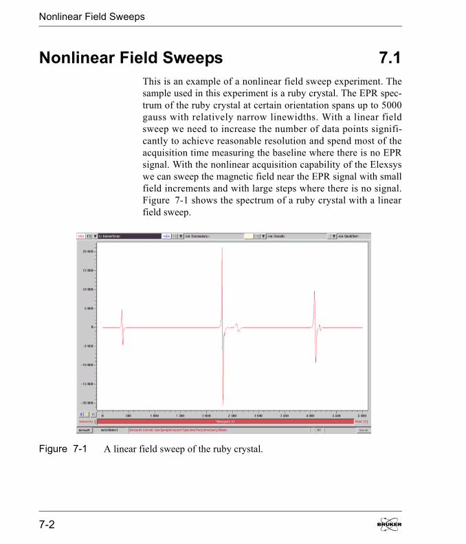
Nonlinear Field Sweeps
Nonlinear Field Sweeps 7.1This is an example of a nonlinear field sweep experiment. Thesample used in this experiment is a ruby crystal. The EPR spec-trum of the ruby crystal at certain orientation spans up to 5000gauss with relatively narrow linewidths. With a linear fieldsweep we need to increase the number of data points signifi-cantly to achieve reasonable resolution and spend most of theacquisition time measuring the baseline where there is no EPRsignal. With the nonlinear acquisition capability of the Elexsyswe can sweep the magnetic field near the EPR signal with smallfield increments and with large steps where there is no signal.Figure 7-1 shows the spectrum of a ruby crystal with a linearfield sweep.
Figure 7-1 A linear field sweep of the ruby crystal.
7-2
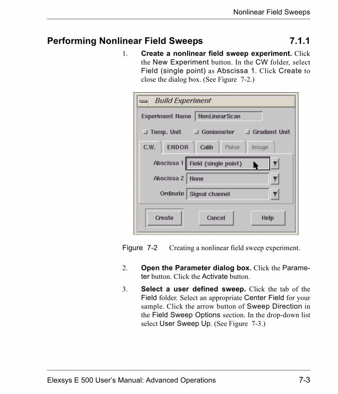
Nonlinear Field Sweeps
Performing Nonlinear Field Sweeps 7.1.11. Create a nonlinear field sweep experiment. Click
the New Experiment button. In the CW folder, selectField (single point) as Abscissa 1. Click Create toclose the dialog box. (See Figure 7-2.)
2. Open the Parameter dialog box. Click the Parame-ter button. Click the Activate button.
3. Select a user defined sweep. Click the tab of theField folder. Select an appropriate Center Field for yoursample. Click the arrow button of Sweep Direction inthe Field Sweep Options section. In the drop-down listselect User Sweep Up. (See Figure 7-3.)
Figure 7-2 Creating a nonlinear field sweep experiment.
Elexsys E 500 User�s Manual: Advanced Operations 7-3

Nonlinear Field Sweeps
Figure 7-3 Selecting a user defined field sweep.
7-4
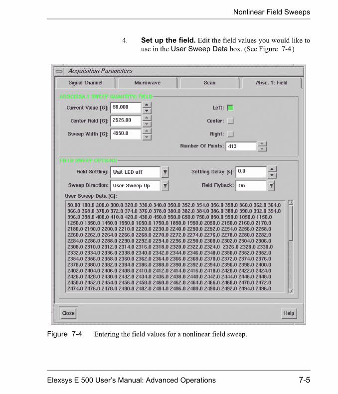
Nonlinear Field Sweeps
4. Set up the field. Edit the field values you would like touse in the User Sweep Data box. (See Figure 7-4.))
Figure 7-4 Entering the field values for a nonlinear field sweep.
Elexsys E 500 User�s Manual: Advanced Operations 7-5
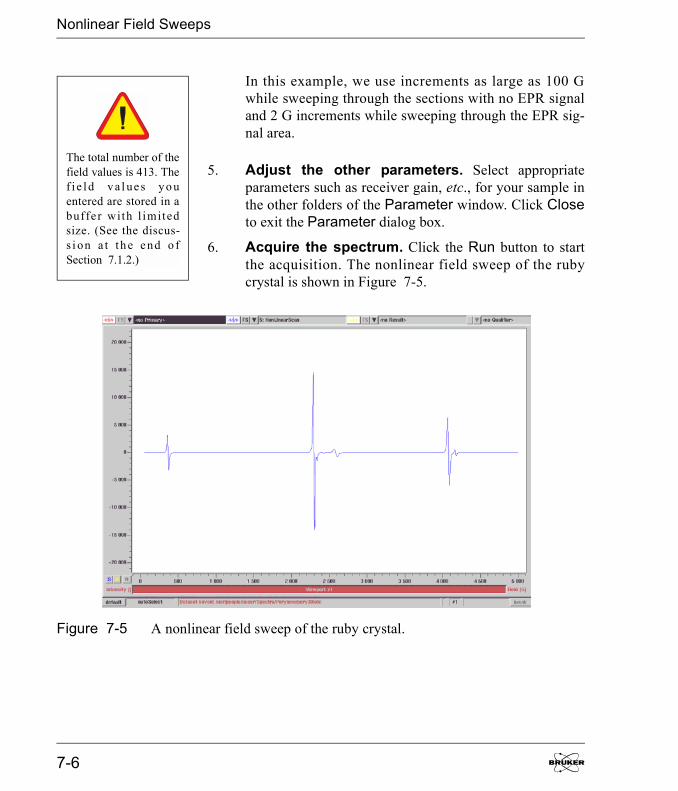
Nonlinear Field Sweeps
In this example, we use increments as large as 100 Gwhile sweeping through the sections with no EPR signaland 2 G increments while sweeping through the EPR sig-nal area.
5. Adjust the other parameters. Select appropriateparameters such as receiver gain, etc., for your sample inthe other folders of the Parameter window. Click Closeto exit the Parameter dialog box.
6. Acquire the spectrum. Click the Run button to startthe acquisition. The nonlinear field sweep of the rubycrystal is shown in Figure 7-5.
The total number of thefield values is 413. Thef i e l d v a l ue s y o uentered are stored in abuffe r with l imitedsize. (See the discus-s i on a t t h e e nd o fSection 7.1.2.)
Figure 7-5 A nonlinear field sweep of the ruby crystal.
7-6
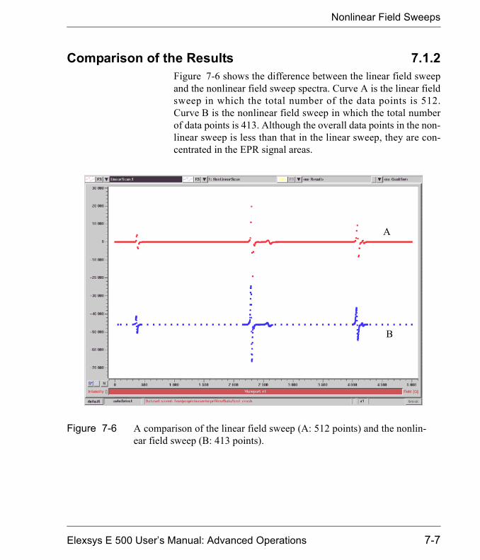
Nonlinear Field Sweeps
Comparison of the Results 7.1.2Figure 7-6 shows the difference between the linear field sweepand the nonlinear field sweep spectra. Curve A is the linear fieldsweep in which the total number of the data points is 512.Curve B is the nonlinear field sweep in which the total numberof data points is 413. Although the overall data points in the non-linear sweep is less than that in the linear sweep, they are con-centrated in the EPR signal areas.
Figure 7-6 A comparison of the linear field sweep (A: 512 points) and the nonlin-ear field sweep (B: 413 points).
A
B
Elexsys E 500 User�s Manual: Advanced Operations 7-7
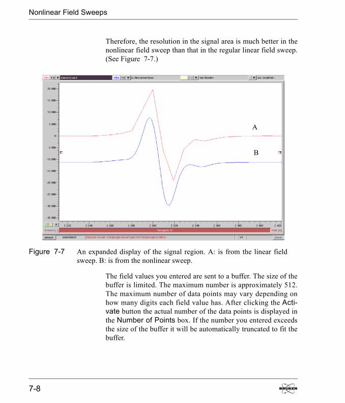
Nonlinear Field Sweeps
Therefore, the resolution in the signal area is much better in thenonlinear field sweep than that in the regular linear field sweep.(See Figure 7-7.)
The field values you entered are sent to a buffer. The size of thebuffer is limited. The maximum number is approximately 512.The maximum number of data points may vary depending onhow many digits each field value has. After clicking the Acti-vate button the actual number of the data points is displayed inthe Number of Points box. If the number you entered exceedsthe size of the buffer it will be automatically truncated to fit thebuffer.
Figure 7-7 An expanded display of the signal region. A: is from the linear fieldsweep. B: is from the nonlinear sweep.
A
B
7-8
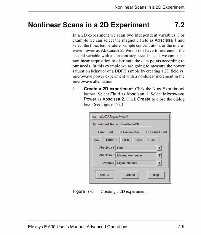
Nonlinear Scans in a 2D Experiment
Nonlinear Scans in a 2D Experiment 7.2In a 2D experiment we scan two independent variables. Forexample we can select the magnetic field as Abscissa 1 andselect the time, temperature, sample concentration, or the micro-wave power as Abscissa 2. We do not have to increment thesecond variable with a constant step-size. Instead, we can use anonlinear acquisition to distribute the data points according toour needs. In this example we are going to measure the powersaturation behavior of a DDPH sample by creating a 2D field vs.microwave power experiment with a nonlinear increment in themicrowave attenuation.
1. Create a 2D experiment. Click the New Experimentbutton. Select Field as Abscissa 1. Select MicrowavePower as Abscissa 2. Click Create to close the dialogbox. (See Figure 7-8.)
Figure 7-8 Creating a 2D experiment.
Elexsys E 500 User�s Manual: Advanced Operations 7-9
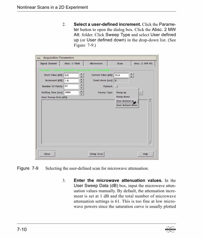
Nonlinear Scans in a 2D Experiment
2. Select a user-defined increment. Click the Parame-ter button to open the dialog box. Click the Absc. 2 MWAtt. folder. Click Sweep Type and select User definedup (or User defined down) in the drop-down list. (SeeFigure 7-9.)
3. Enter the microwave attenuation values. In theUser Sweep Data (dB) box, input the microwave atten-uation values manually. By default, the attenuation incre-ment is set at 1 dB and the total number of microwaveattenuation settings is 61. This is too fine at low micro-wave powers since the saturation curve is usually plotted
Figure 7-9 Selecting the user-defined scan for microwave attenuation.
7-10
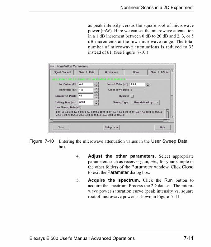
Nonlinear Scans in a 2D Experiment
as peak intensity versus the square root of microwavepower (mW). Here we can set the microwave attenuationin a 1 dB increment between 0 dB to 20 dB and 2, 3, or 5dB increments at the low microwave range. The totalnumber of microwave attenuations is reduced to 33instead of 61. (See Figure 7-10.)
4. Adjust the other parameters. Select appropriateparameters such as receiver gain, etc., for your sample inthe other folders of the Parameter window. Click Closeto exit the Parameter dialog box.
5. Acquire the spectrum. Click the Run button toacquire the spectrum. Process the 2D dataset. The micro-wave power saturation curve (peak intensity vs. squareroot of microwave power is shown in Figure 7-11.
Figure 7-10 Entering the microwave attenuation values in the User Sweep Databox.
Elexsys E 500 User�s Manual: Advanced Operations 7-11
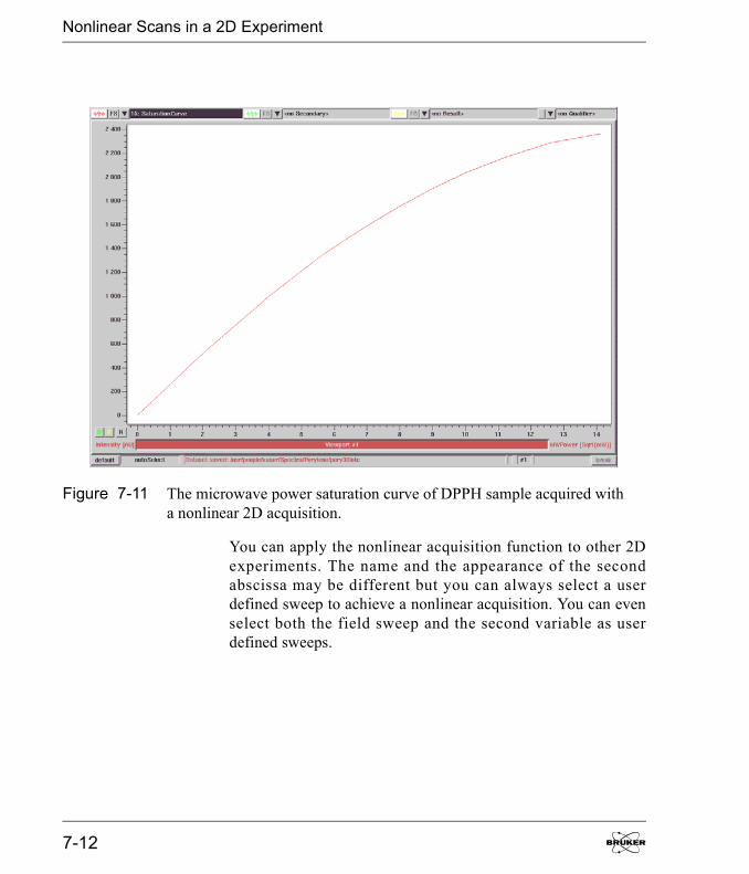
Nonlinear Scans in a 2D Experiment
You can apply the nonlinear acquisition function to other 2Dexperiments. The name and the appearance of the secondabscissa may be different but you can always select a userdefined sweep to achieve a nonlinear acquisition. You can evenselect both the field sweep and the second variable as userdefined sweeps.
Figure 7-11 The microwave power saturation curve of DPPH sample acquired witha nonlinear 2D acquisition.
7-12
Macros 8We have implemented macros in Xepr to give users more conve-nience and freedom to customize their software. A macro is astored list of commands that can be executed in order to auto-mate routine tasks such as data processing or data acquisition. Itis especially convenient for routine processing of large amountsof spectra. In the first section we will introduce the automaticrecording method to make a macro. You do not need to knowany macro commands or terms to create your own macro. Thesecond section will guide you through the basic commands of amacro so you can write your own macro using a text editor. Thismethod allows you to use arguments and create dialog boxes in amacro.
Elexsys E 500 User�s Manual: Advanced Operations
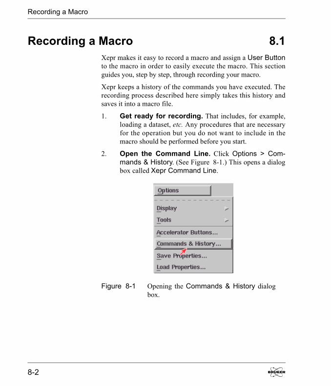
Recording a Macro
Recording a Macro 8.1Xepr makes it easy to record a macro and assign a User Buttonto the macro in order to easily execute the macro. This sectionguides you, step by step, through recording your macro.
Xepr keeps a history of the commands you have executed. Therecording process described here simply takes this history andsaves it into a macro file.
1. Get ready for recording. That includes, for example,loading a dataset, etc. Any procedures that are necessaryfor the operation but you do not want to include in themacro should be performed before you start.
2. Open the Command Line. Click Options > Com-mands & History. (See Figure 8-1.) This opens a dialogbox called Xepr Command Line.
Figure 8-1 Opening the Commands & History dialogbox.
8-2
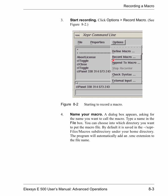
Recording a Macro
3. Start recording. Click Options > Record Macro. (SeeFigure 8-2.)
4. Name your macro. A dialog box appears, asking forthe name you want to call the macro. Type a name in theFile box. You can choose into which directory you wantto put the macro file. By default it is saved in the ~/xepr-Files/Macros subdirectory under your home directory.The program will automatically add an .xmc extension tothe file name.
Figure 8-2 Starting to record a macro.
Elexsys E 500 User�s Manual: Advanced Operations 8-3
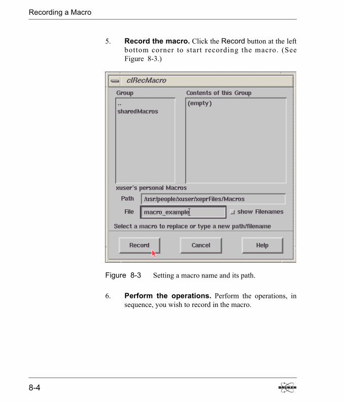
Recording a Macro
5. Record the macro. Click the Record button at the leftbottom corner to start recording the macro. (SeeFigure 8-3.)
6. Perform the operations. Perform the operations, insequence, you wish to record in the macro.
Figure 8-3 Setting a macro name and its path.
8-4
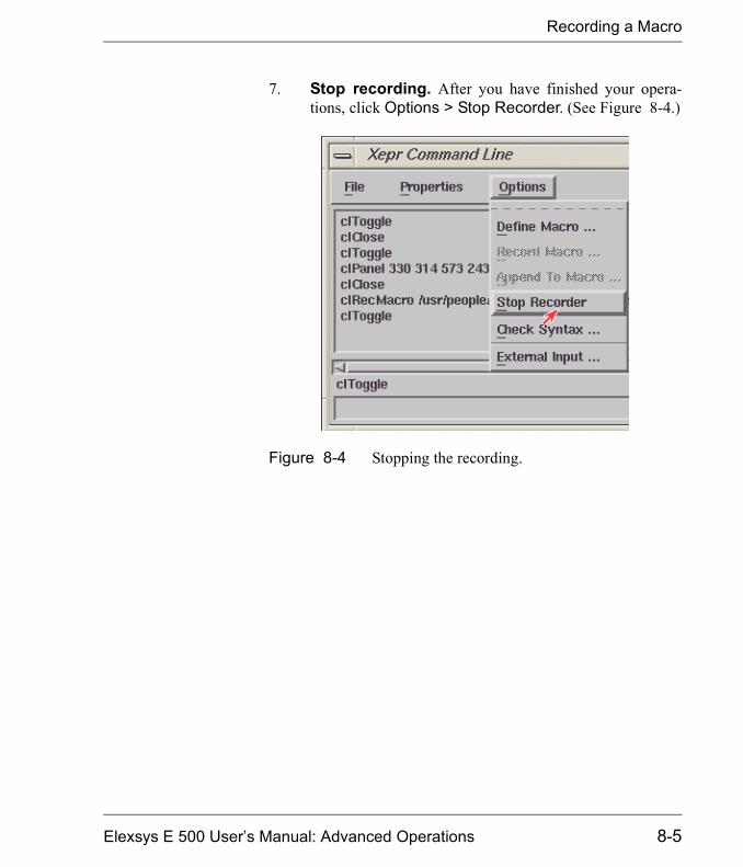
Recording a Macro
7. Stop recording. After you have finished your opera-tions, click Options > Stop Recorder. (See Figure 8-4.)
Figure 8-4 Stopping the recording.
Elexsys E 500 User�s Manual: Advanced Operations 8-5
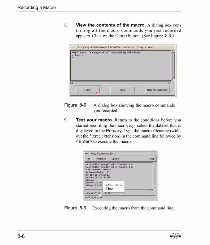
Recording a Macro
8. View the contents of the macro. A dialog box con-taining all the macro commands you just recordedappears. Click on the Close button. (See Figure 8-5.)
9. Test your macro. Return to the conditions before youstarted recording the macro, e.g. select the dataset that isdisplayed in the Primary. Type the macro filename (with-out the *.xmc extension) in the command line followed by<Enter> to execute the macro.
Figure 8-5 A dialog box showing the macro commandsyou recorded.
Figure 8-6 Executing the macro from the command line.
CommandLine
8-6
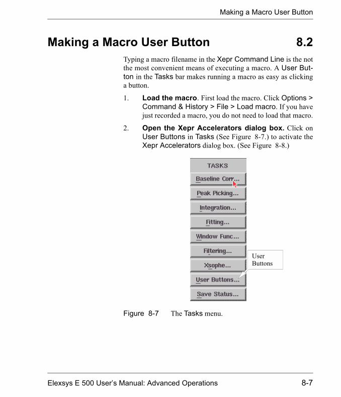
Making a Macro User Button
Making a Macro User Button 8.2Typing a macro filename in the Xepr Command Line is the notthe most convenient means of executing a macro. A User But-ton in the Tasks bar makes running a macro as easy as clickinga button.
1. Load the macro. First load the macro. Click Options >Command & History > File > Load macro. If you havejust recorded a macro, you do not need to load that macro.
2. Open the Xepr Accelerators dialog box. Click onUser Buttons in Tasks (See Figure 8-7.) to activate theXepr Accelerators dialog box. (See Figure 8-8.)
Figure 8-7 The Tasks menu.
UserButtons
Elexsys E 500 User�s Manual: Advanced Operations 8-7

Making a Macro User Button
3. Define the macro. Click on define button. If you cannot find define button you can click File > DefineMacro.
4. Name the user button. In the acDefButton dialog boxtype a name for the button. (See Figure 8-9.)
5. Select a hot key for your macro. You need to assigna hot key for your macro in the Key column. Special rulesapply to assigning a hot key. You can find those rules inthe Help menu.
Figure 8-8 Defining the user button.
Figure 8-9 Defining the user button properties.
8-8

Making a Macro User Button
6. Enter a command line. Enter the macro filename with-out the *.xmc extension. (See Figure 8-9.)
7. Assign a color to the button. Grouping buttons bycolor helps organize your macros. To choose a color otherthan the default color, click the desired Group button.
8. Finish defining the user button. Click Apply andthen Close to finish making the user button. The newlydefined button should appear in the Xepr Acceleratorsdialog box.(See Figure 8-10.)
9. Test your macro. Return to the conditions before youstarted recording the macro, e.g. select the dataset that isdisplayed in the Primary. Click on the user button to exe-cute the macro.
Figure 8-10 The macro buttons in the Xepr Accelera-tors box.
Elexsys E 500 User�s Manual: Advanced Operations 8-9

Writing a Macro with a Text Editor
Writing a Macro with a Text Editor 8.3You can also write a macro using any text editor. Simply saveyour file with an *.xmc extension for macro files. Writing amacro with this method allows you to use arguments, create adialog box, direct the macro to terminate upon an error, andchoose whether the macro executed commands will be recordedin the data history.
Special Macro Commands 8.3.1In addition to the normal Xepr commands that are executed bythe macro, there are special macro commands that are precededby a �%� character. These special commands control how themacro executes and allow you to pass data to the various Xeprcommands in the macro. All special macro commands must beuppercase.
%DESC This command briefly describes the macro. The string after%DESC is similar to the title of a dataset. For example,%DESC Example indicates this macro is an example and thestring �Example� will appear in the dialog box as a title whenyou load the macro. It will also be displayed when you type themacro name into the command line.
%TERM If this statement is present, the macro terminates if an internalerror occurs. No additional statement is needed.
%NOHIS If this options is present, commands in your macro will not gen-erate history output. Instead, only the macro itself will produce ahistory line like any other Xepr command.
8-10
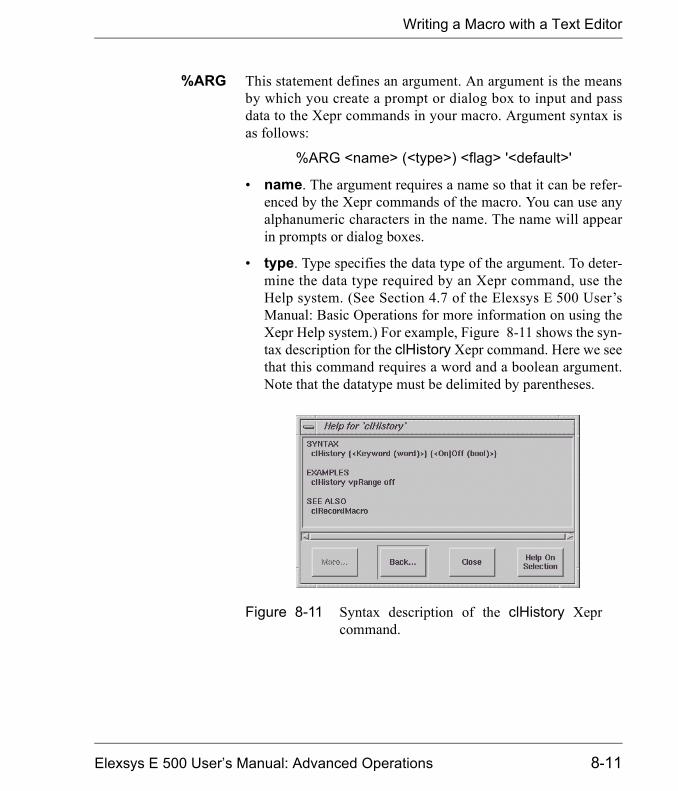
Writing a Macro with a Text Editor
%ARG This statement defines an argument. An argument is the meansby which you create a prompt or dialog box to input and passdata to the Xepr commands in your macro. Argument syntax isas follows:
%ARG <name> (<type>) <flag> '<default>'
� name. The argument requires a name so that it can be refer-enced by the Xepr commands of the macro. You can use anyalphanumeric characters in the name. The name will appearin prompts or dialog boxes.
� type. Type specifies the data type of the argument. To deter-mine the data type required by an Xepr command, use theHelp system. (See Section 4.7 of the Elexsys E 500 User�sManual: Basic Operations for more information on using theXepr Help system.) For example, Figure 8-11 shows the syn-tax description for the clHistory Xepr command. Here we seethat this command requires a word and a boolean argument.Note that the datatype must be delimited by parentheses.
Figure 8-11 Syntax description of the clHistory Xeprcommand.
Elexsys E 500 User�s Manual: Advanced Operations 8-11

Writing a Macro with a Text Editor
The data type must be one of the following:
� Flag. There are three flags available that determine how theargument value will be entered.
! The argument value is required right from the start.
# The argument value will be entered in a dialog box.
? The default value will be used if the argument value is notentered.
� �<default>� The string enclosed by the apostrophes definesthe default value. If no default value is specified, the lastvalue for that argument will be the default value. For switchor boolean arguments, this string defines the allowed values,e.g. '<value1|value2|value3>', where the first one is thedefault value.
Data Type Definition
INT_ARG integer
CARD_ARG cardinal number (integer ����
FLOAT_ARG floating point number
COLOR_ARG color (used to change background colors, etc.)
WORD_ARG a single word
TEXT_ARG text string (can contain spaces and punctuation)
SWITCH_ARG several strings, only one of which can be selected
BOOL_ARG logic value with only two possible values, On or Off
PAF_ARG pointer to a file
Table 8-1 Definition of data types.
8-12

Writing a Macro with a Text Editor
To call an argument in you macro body, simply type $<name>in place of using a constant value.
An ArgumentExample
As an example, the following section of a macro file will pro-duce the following dialog box to prompt you for input. (SeeFigure 8-12.)
%DESC Macro loading & displaying a dataset %NOHIS%TERM %ARG INT_ARG (INT_ARG)# '1'%ARG CARD_ARG (CARD_ARG)#%ARG FLOAT_ARG (FLOAT_ARG)#%ARG COLOR_ARG (COLOR_ARG)#%ARG WORD_ARG (WORD_ARG)#%ARG TEXT_ARG (TEXT_ARG)#%ARG SWITCH_ARG (SWITCH_ARG)# 'Choice1|Choice2|Choice3'%ARG BOOL_ARG (BOOL_ARG)# 'On|Off'%ARG PAF_ARG (PAF_ARG)#
Elexsys E 500 User�s Manual: Advanced Operations 8-13

Writing a Macro with a Text Editor
Figure 8-12 A dialog box prompting for input.
8-14

Writing a Macro with a Text Editor
The Macro Body 8.3.2The macro body consists of comments and commands. Linesstarting with an asterisk (*) are marked as comments and areignored by Xepr. Any Xepr command can be a macro command.Refer to the Xepr software manual or Help for available Xeprcommands. No end statement is necessary.
A Macro Example 8.3.3The following example macro prompts you for a data filename,a data handle, and whether you want to convert the abscissatype. It then loads the selected data file into Xepr under the spec-ified handle number, displays it in the current Primary viewport,and then converts the abscissa to the selected type. The com-mands in the macro will not appear in the history except themacro itself. It will terminate upon internal error. It containsthree arguments: the file name, the data handle number, and theabscissa type.
%DESC Macro loading & displaying a dataset%NOHIS%TERM%ARG paF (PAF_ARG) #%ARG number (CARD_ARG) #%ARG axis (SWITCH_ARG) # 'indexed|index-gauged|n-tuple'* Load the datasetddLoad $paF $number* switch off all other datasets in current viewportvpCurrent -1 Secondary 0vpCurrent -1 Qualifier 0prNoOp -1* now display newly loaded data setvpCurrent -1 $numberddAbscType $number $axis
Elexsys E 500 User�s Manual: Advanced Operations 8-15

Writing a Macro with a Text Editor
Type the above example in a text editor and save it as exam-ple.xmc. Load the macro and enter example in the commandline. You can also follow the procedure in Section 8.2 to make ita user button.
The prompt for the macro will look as follows.
Figure 8-13 An example prompt.
8-16

Automatic Post-Processing 9The Xepr software offers an automatic post processing feature.After an acquisition is finished, this feature executes a sequenceof commands that you have defined. This feature can combineacquisition, data processing, and data storage operations into oneaction. It also accepts task-bar routines and user-made macros.
Elexsys E 500 User�s Manual: Advanced Operations
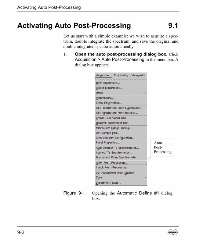
Activating Auto Post-Processing
Activating Auto Post-Processing 9.1Let us start with a simple example: we wish to acquire a spec-trum, double integrate the spectrum, and save the original anddouble integrated spectra automatically.
1. Open the auto post-processing dialog box. ClickAcquisition > Auto Post-Processing in the menu bar. Adialog box appears.
Figure 9-1 Opening the Automatic Define #1 dialogbox.
AutoPost-Processing
9-2
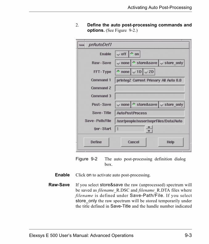
Activating Auto Post-Processing
2. Define the auto post-processing commands andoptions. (See Figure 9-2.)
Enable Click on to activate auto post-processing.
Raw-Save If you select store&save the raw (unprocessed) spectrum willbe saved as filename_R.DSC and filename_R.DTA files wherefilename is defined under Save-Path/File. If you selectstore_only the raw spectrum will be stored temporarily underthe title defined in Save-Title and the handle number indicated
Figure 9-2 The auto post-processing definition dialogbox.
Elexsys E 500 User�s Manual: Advanced Operations 9-3

Activating Auto Post-Processing
by $nr-Start. none specifies the raw dataset is to be neithersaved nor stored.
FFT-Type If you want to perform a Fast Fourier Transformation you needto select either 1D or 2D for one or two dimensional transforms.Otherwise select none.
Command Command 1, 2, and 3 define the Xepr commands to be exe-cuted. Each entry accepts one command. You may enter as manyas three commands in this dialog box. Refer to the next sectionfor entering more than three commands. In this example we usethe command for automatic double integration. To find the Xeprcommand for the function you want to use, execute that functionand look at either Help > Main Help or Options > Command& History. You can also enter the name of a macro or ProDeLprogram in the command line.
Post-Save If you select store&save the post-processed spectrum will besaved as filename_P.DSC and filename_P.DTA files where file-name is defined under Save-Path/File. If you select store_onlythe processed spectrum will be stored temporarily under the titledefined in Save-Title and the handle number indicated by$nr-Start. none specifies the processed dataset is to be neithersaved nor stored.
Save-Title Enter the title you want to use if you selected save&store orstore_only options.
Save-Path/File Enter the path followed by the filename if you selected thesave&store option in Raw-Save or Post-Save. Make sure thedirectory exists and you have permission to write to that direc-tory. You can use a variable, $nr as part of the file name so thatthe file name automatically increments when multiple acquisi-tions are set. For example, you can set the file name as test$nrand the saved files will be test1_R, test2_R ..., if you clickedthe Raw-Save button and set $nr-Start to 1. (See next item.)
9-4

Activating Auto Post-Processing
$nr-Start If you choose to save the spectrum and use $nr in the file namethis is the initial value of the $nr variable. If you choose to storethe spectra only, this is the handle number assigned to the datastored in the data table. It will automatically update to the firstavailable handle number if it is set to -1. You can force the han-dle number to a specific value by entering that number.
3. Close the dialog box. Click the Define button to closethe dialog box.
Elexsys E 500 User�s Manual: Advanced Operations 9-5
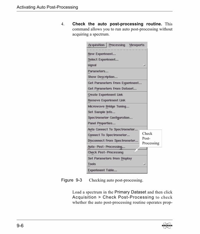
Activating Auto Post-Processing
4. Check the auto post-processing routine. Thiscommand allows you to run auto post-processing withoutacquiring a spectrum.
Load a spectrum in the Primary Dataset and then clickAcquisition > Check Post-Processing to checkwhether the auto post-processing routine operates prop-
Figure 9-3 Checking auto post-processing.
CheckPost-Processing
9-6
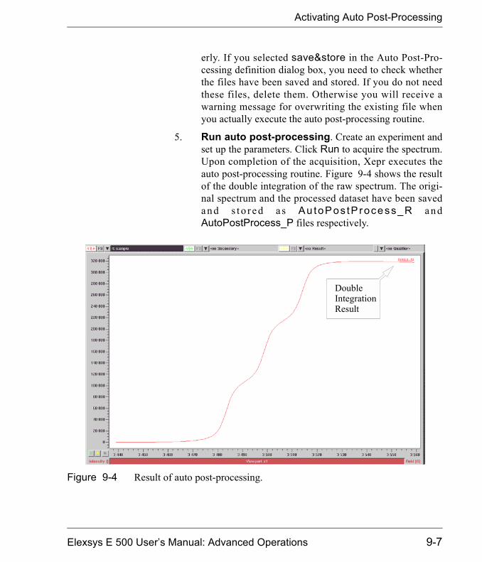
Activating Auto Post-Processing
erly. If you selected save&store in the Auto Post-Pro-cessing definition dialog box, you need to check whetherthe files have been saved and stored. If you do not needthese files, delete them. Otherwise you will receive awarning message for overwriting the existing file whenyou actually execute the auto post-processing routine.
5. Run auto post-processing. Create an experiment andset up the parameters. Click Run to acquire the spectrum.Upon completion of the acquisition, Xepr executes theauto post-processing routine. Figure 9-4 shows the resultof the double integration of the raw spectrum. The origi-nal spectrum and the processed dataset have been saveda n d s t o r e d a s Au toPos tP rocess_R a n dAutoPostProcess_P files respectively.
Figure 9-4 Result of auto post-processing.
DoubleIntegrationResult
Elexsys E 500 User�s Manual: Advanced Operations 9-7
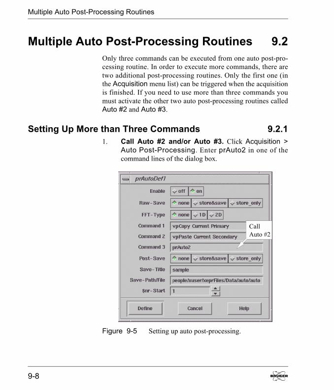
Multiple Auto Post-Processing Routines
Multiple Auto Post-Processing Routines 9.2Only three commands can be executed from one auto post-pro-cessing routine. In order to execute more commands, there aretwo additional post-processing routines. Only the first one (inthe Acquisition menu list) can be triggered when the acquisitionis finished. If you need to use more than three commands youmust activate the other two auto post-processing routines calledAuto #2 and Auto #3.
Setting Up More than Three Commands 9.2.11. Call Auto #2 and/or Auto #3. Click Acquisition >
Auto Post-Processing. Enter prAuto2 in one of thecommand lines of the dialog box.
Figure 9-5 Setting up auto post-processing.
CallAuto #2
9-8

Multiple Auto Post-Processing Routines
You can also enter prAuto3 if needed and if there is acommand entry available. (See Figure 9-5.) In this exam-ple, the Primary dataset will be copied and pasted to theSecondary Dataset. This way we will be able to applydifferent processes to the original dataset. Then it calls thesecond auto post-processing function Auto #2.
2. Open the second auto post-processing dialogbox. Click Processing > Automatic > Define #2 toopen the dialog box. (See Figure 9-6.)
Figure 9-6 Opening the Automatic Define #2 dialogbox.
OpenAuto #2
Elexsys E 500 User�s Manual: Advanced Operations 9-9
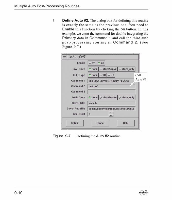
Multiple Auto Post-Processing Routines
3. Define Auto #2. The dialog box for defining this routineis exactly the same as the previous one. You need toEnable this function by clicking the on button. In thisexample, we enter the command for double integrating thePrimary data in Command 1 and call the third autopos t -p rocess ing rou t ine in Command 2 . (S eeFigure 9-7.)
Figure 9-7 Defining the Auto #2 routine.
CallAuto #3
9-10
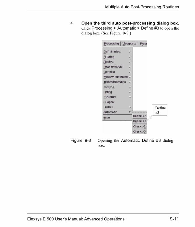
Multiple Auto Post-Processing Routines
4. Open the third auto post-processing dialog box.Click Processing > Automatic > Define #3 to open thedialog box. (See Figure 9-8.)
Figure 9-8 Opening the Automatic Define #3 dialogbox.
Define#3
Elexsys E 500 User�s Manual: Advanced Operations 9-11
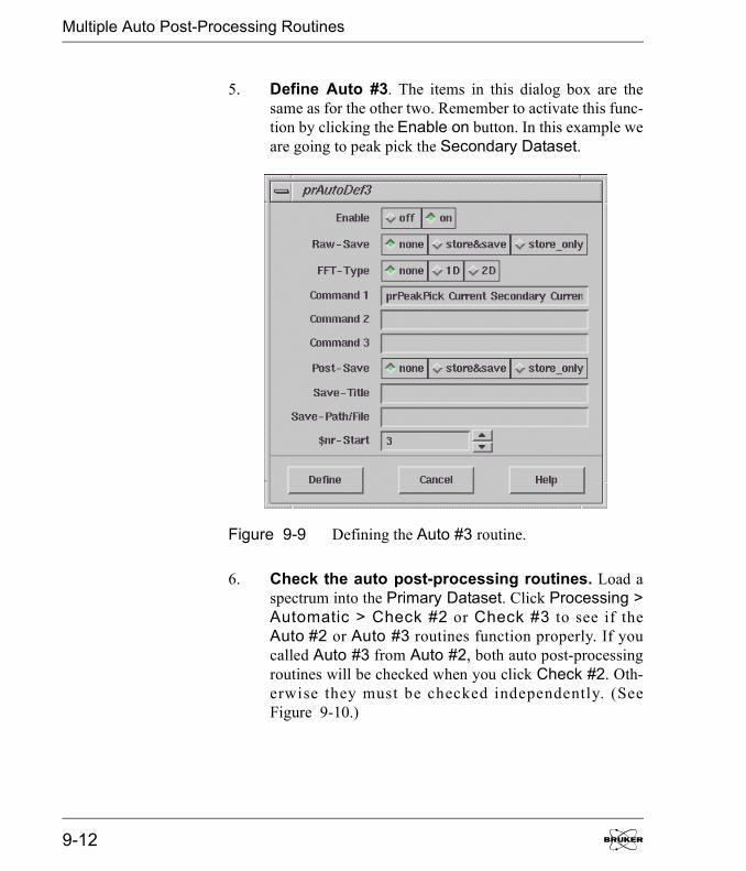
Multiple Auto Post-Processing Routines
5. Define Auto #3. The items in this dialog box are thesame as for the other two. Remember to activate this func-tion by clicking the Enable on button. In this example weare going to peak pick the Secondary Dataset.
6. Check the auto post-processing routines. Load aspectrum into the Primary Dataset. Click Processing >Automatic > Check #2 or Check #3 to see if theAuto #2 or Auto #3 routines function properly. If youcalled Auto #3 from Auto #2, both auto post-processingroutines will be checked when you click Check #2. Oth-erwise they must be checked independently. (SeeFigure 9-10.)
Figure 9-9 Defining the Auto #3 routine.
9-12
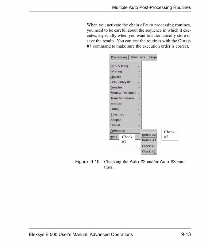
Multiple Auto Post-Processing Routines
When you activate the chain of auto processing routines,you need to be careful about the sequence in which it exe-cutes, especially when you want to automatically store orsave the results. You can test the routines with the Check#1 command to make sure the execution order is correct.
Figure 9-10 Checking the Auto #2 and/or Auto #3 rou-tines.
Check#2Check
#3
Elexsys E 500 User�s Manual: Advanced Operations 9-13

Multiple Auto Post-Processing Routines
7. Execute the multiple auto post-processing rou-tines. Create or load an experiment and set up the param-eters. Click Run to acquire the spectrum. The autopost-processing routines should execute sequentially. Inthis example the results of the auto-processing are shownin Figure 9-11.
Figure 9-11 Results of a series of auto post-processing routines.
DoubleIntegrationResult
OriginalSpectrum
PeakPickingResult
9-14
Implementing Help 10One of the powerful features of the Xepr software is that you cancustomize your Xepr program by utilizing Xepr macros andProDeL programs. In order to share these customized routinesand functions with your fellow users, they must know how touse them. The Xepr help system allows you to implement yourown instructions for these customized functions or routines. Thehelp files can include definitions, descriptions, command andargument syntax, helpful hints, related command, etc. This chap-ter will describe how to implement your own help files in theXepr help system.
Writing a Help File 10.1
Help File Format 10.1.1Xepr help files are plain ASCII text files. You can use any texteditor to compose the help file. No special format is required.There are two important statements: DESC and MORE. DESCindicates the start of the text to be displayed in the help window.All text preceding the statement is not displayed. If the file is toolong to display in one help window, type the MORE commandinto the help file to divide the file into more manageable sec-tions. When viewing the help file, the More button in the helpdialog box advances you to the next section. You can use MOREas many times as you wish if the file is very long. The Back but-ton in the help dialog box returns you to the previous section.The following page shows an example help file.
Elexsys E 500 User�s Manual: Advanced Operations
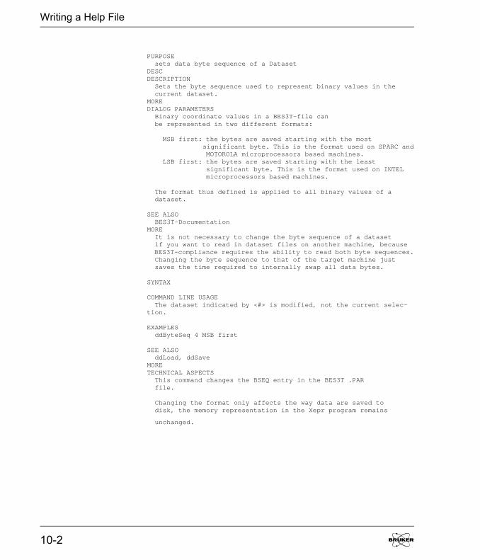
Writing a Help File
PURPOSE sets data byte sequence of a DatasetDESCDESCRIPTION Sets the byte sequence used to represent binary values in the current dataset.MOREDIALOG PARAMETERS Binary coordinate values in a BES3T-file can be represented in two different formats:
MSB first: the bytes are saved starting with the most significant byte. This is the format used on SPARC and MOTOROLA microprocessors based machines. LSB first: the bytes are saved starting with the least significant byte. This is the format used on INTEL microprocessors based machines.
The format thus defined is applied to all binary values of a dataset.
SEE ALSO BES3T-DocumentationMORE It is not necessary to change the byte sequence of a dataset if you want to read in dataset files on another machine, because BES3T-compliance requires the ability to read both byte sequences. Changing the byte sequence to that of the target machine just saves the time required to internally swap all data bytes.
SYNTAX
COMMAND LINE USAGE The dataset indicated by <#> is modified, not the current selec-tion.
EXAMPLES ddByteSeq 4 MSB first
SEE ALSO ddLoad, ddSaveMORETECHNICAL ASPECTS This command changes the BSEQ entry in the BES3T .PAR file.
Changing the format only affects the way data are saved to disk, the memory representation in the Xepr program remains
unchanged.
10-2

Writing a Help File
Help Filenames 10.1.2The help filename for a command must be identical to the com-mand name. No extension is needed. For example, if the macroyou made is called eXample and saved as eXample.xmc, thehelp file for this macro must be named eXample without exten-sion.
Where to Put the Help Files 10.1.3Access to a help file is determined by the location of the file. Ifyou want every user from all accounts to be able to see a helpfile you need to save the file in the /usr/xepr/sharedHelpfolder. Note that you need root privileges to do so. If you want tolimit access to one user account, e.g. xuser, save the file in/usr/people/xuser/xeprFiles/Help on an SGI system runningIRIX and only those who log in as xuser have access to this helpfile. For a Linux system, put the file in the /home/xuser/xepr-Files/Help directory.
Elexsys E 500 User�s Manual: Advanced Operations 10-3
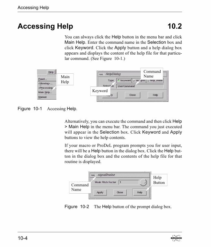
Accessing Help
Accessing Help 10.2You can always click the Help button in the menu bar and clickMain Help. Enter the command name in the Selection box andclick Keyword. Click the Apply button and a help dialog boxappears and displays the content of the help file for that particu-lar command. (See Figure 10-1.)
Alternatively, you can execute the command and then click Help> Main Help in the menu bar. The command you just executedwill appear in the Selection box. Click Keyword and Applybuttons to view the help contents.
If your macro or ProDeL program prompts you for user input,there will be a Help button in the dialog box. Click the Help but-ton in the dialog box and the contents of the help file for thatroutine is displayed.
Figure 10-1 Accessing Help.
MainHelp
Keyword
CommandName
Figure 10-2 The Help button of the prompt dialog box.
HelpButtonCommand
Name
10-4

Changing Microwave Bridges 11
Removing the Microwave Bridge 11.11. Turn off the spectrometer. Follow the procedures in
Chapter 3 of the Elexsys E 500 User�s Manual: BasicOperations to turn off the spectrometer if it is still on.Close the water valves.
2. Remove the cavity. Follow the instructions ofSection 7.2 of the Elexsys E 500 User�s Manual: BasicOperations to remove the cavity. Remove the waveguideextension from the bridge as well.
3. Disconnect the cooling water. Not all bridges requirewater cooling. If the current bridge has water cooling, firstclose the water valves for the bridge. Disconnect the waterhose to and from the bridge. (See Figure 11-1.) Block thewater hose to prevent water spillage.
Figure 11-1 The cooling water connectors for the microwave bridge.
CoolingWaterConnector
CoolingWaterConnector
Elexsys E 500 User�s Manual: Advanced Operations
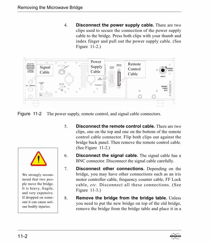
Removing the Microwave Bridge
4. Disconnect the power supply cable. There are twoclips used to secure the connection of the power supplycable to the bridge. Press both clips with your thumb andindex finger and pull out the power supply cable. (SeeFigure 11-2.)
5. Disconnect the remote control cable. There are twoclips, one on the top and one on the bottom of the remotecontrol cable connector. Flip both clips out against thebridge back panel. Then remove the remote control cable.(See Figure 11-2.)
6. Disconnect the signal cable. The signal cable has aBNC connector. Disconnect the signal cable carefully.
7. Disconnect other connections. Depending on thebridge, you may have other connections such as an irismotor controller cable, frequency counter cable, FF Lockcable, etc. Disconnect all these connections. (SeeFigure 11-3.)
8. Remove the bridge from the bridge table. Unlessyou need to put the new bridge on top of the old bridge,remove the bridge from the bridge table and place it in a
Figure 11-2 The power supply, remote control, and signal cable connectors.
RemoteControlCable
PowerSupplyCable
SignalCable
We strongly recom-mend that two peo-ple move the bridge.It is heavy, fragile,and very expensive.If dropped on some-one it can cause seri-ous bodily injuries.
11-2

Removing the Microwave Bridge
safe place. Cover the waveguide opening on the bridgewith the waveguide cover to prevent dust from enteringthe waveguide.
Figure 11-3 Other bridge connections.
IrisMotorConnector
FrequencyCounterConnector
MicrowaveOutput
Elexsys E 500 User�s Manual: Advanced Operations 11-3

Installing a Microwave Bridge
Installing a Microwave Bridge 11.21. Put the microwave bridge on top of the bridge
table. Some non X-band bridges actually sit on top of theX-band bridge.
2. Attach the waveguide extension. For some cavitiesyou need to attach the waveguide extension to the bridge.
Align the waveguide
Figure 11-4 The waveguide extension.
We strongly recom-mend that two peo-ple move the bridge.It is heavy, fragile,and very expensive.If dropped on some-one it can cause seri-ous bodily injuries.
WaveguideExtension
11-4
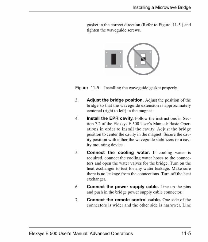
Installing a Microwave Bridge
gasket in the correct direction (Refer to Figure 11-5.) andtighten the waveguide screws.
3. Adjust the bridge position. Adjust the position of thebridge so that the waveguide extension is approximatelycentered (right to left) in the magnet.
4. Install the EPR cavity. Follow the instructions in Sec-tion 7.2 of the Elexsys E 500 User�s Manual: Basic Oper-ations in order to install the cavity. Adjust the bridgeposition to center the cavity in the magnet. Secure the cav-ity position with either the waveguide stabilizers or a cav-ity mounting device.
5. Connect the cooling water. If cooling water isrequired, connect the cooling water hoses to the connec-tors and open the water valves for the bridge. Turn on theheat exchanger to test for any water leakage. Make surethere is no leakage from the connections. Turn off the heatexchanger.
6. Connect the power supply cable. Line up the pinsand push in the bridge power supply cable connector.
7. Connect the remote control cable. One side of theconnectors is wider and the other side is narrower. Line
Figure 11-5 Installing the waveguide gasket properly.
Elexsys E 500 User�s Manual: Advanced Operations 11-5
Installing a Microwave Bridge
them up and push in the connector. Flip the two clips tosecure the connection.
8. Connect the signal cable. The signal cable has a BNCconnector. Push it in and rotate to secure the connection.There are two 50 ohm signal output from the bridge. Con-nect the signal cable to either one of them.
9. Connect other accessories. If you have auto tuningcapabilities, connect the iris motor cable. If you haveother accessories to connect to the bridge, connect themaccordingly.
11-6
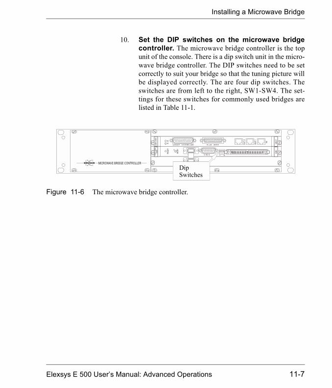
Installing a Microwave Bridge
10. Set the DIP switches on the microwave bridgecontroller. The microwave bridge controller is the topunit of the console. There is a dip switch unit in the micro-wave bridge controller. The DIP switches need to be setcorrectly to suit your bridge so that the tuning picture willbe displayed correctly. The are four dip switches. Theswitches are from left to the right, SW1-SW4. The set-tings for these switches for commonly used bridges arelisted in Table 11-1.
Figure 11-6 The microwave bridge controller.
DipSwitches
Elexsys E 500 User�s Manual: Advanced Operations 11-7
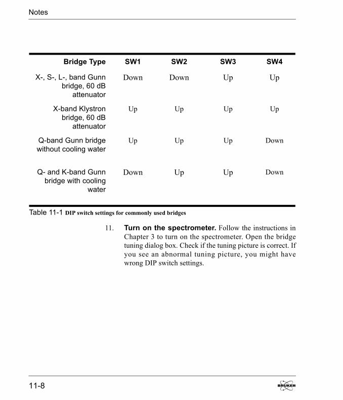
Notes
11. Turn on the spectrometer. Follow the instructions inChapter 3 to turn on the spectrometer. Open the bridgetuning dialog box. Check if the tuning picture is correct. Ifyou see an abnormal tuning picture, you might havewrong DIP switch settings.
Bridge Type SW1 SW2 SW3 SW4
X-, S-, L-, band Gunnbridge, 60 dB
attenuator
Down Down Up Up
X-band Klystronbridge, 60 dB
attenuator
Up Up Up Up
Q-band Gunn bridgewithout cooling water
Up Up Up Down
Q- and K-band Gunnbridge with cooling
water
Down Up Up Down
Table 11-1 DIP switch settings for commonly used bridges
11-8

Installing & Using Accessories 12Bruker offers many optional accessories for the Elexsys seriesspectrometers. In this chapter, we shall concentrate on aspectsthat directly relate to the use of these products with the Xeprsoftware. Most of the accessories have their own individualmanuals: consult their documentation for further informationand details.
Elexsys E 500 User�s Manual: Advanced Operations
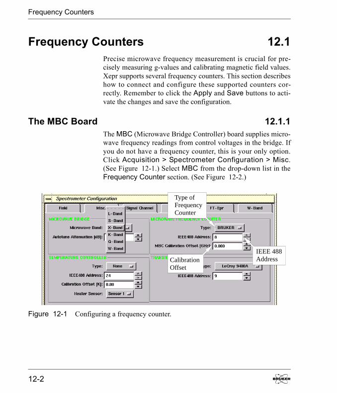
Frequency Counters
Frequency Counters 12.1Precise microwave frequency measurement is crucial for pre-cisely measuring g-values and calibrating magnetic field values.Xepr supports several frequency counters. This section describeshow to connect and configure these supported counters cor-rectly. Remember to click the Apply and Save buttons to acti-vate the changes and save the configuration.
The MBC Board 12.1.1The MBC (Microwave Bridge Controller) board supplies micro-wave frequency readings from control voltages in the bridge. Ifyou do not have a frequency counter, this is your only option.Click Acquisition > Spectrometer Configuration > Misc.(See Figure 12-1.) Select MBC from the drop-down list in theFrequency Counter section. (See Figure 12-2.)
Figure 12-1 Configuring a frequency counter.
Type ofFrequencyCounter
IEEE 488AddressCalibration
Offset
12-2
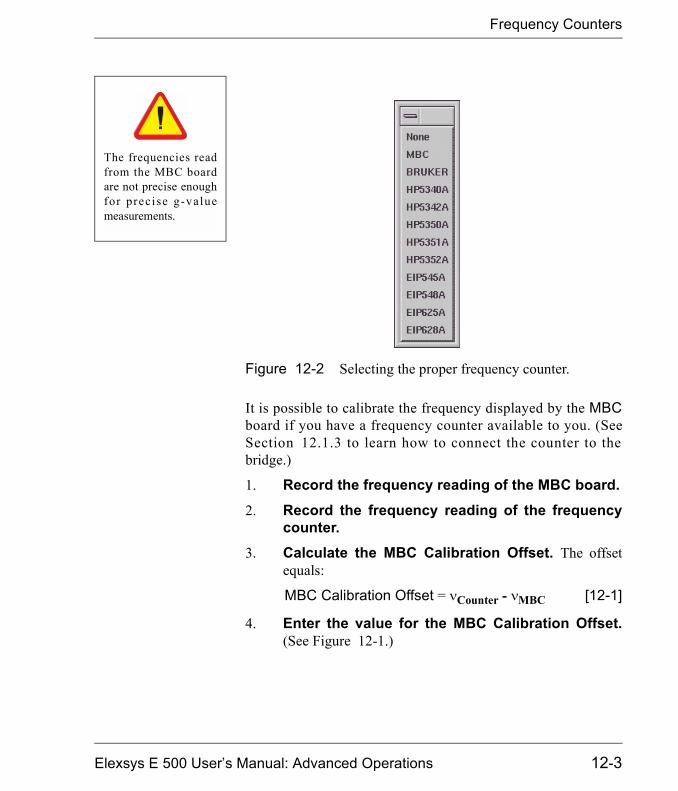
Frequency Counters
It is possible to calibrate the frequency displayed by the MBCboard if you have a frequency counter available to you. (SeeSection 12.1.3 to learn how to connect the counter to thebridge.)
1. Record the frequency reading of the MBC board.2. Record the frequency reading of the frequency
counter.3. Calculate the MBC Calibration Offset. The offset
equals:
MBC Calibration Offset = �Counter - �MBC [12-1]
4. Enter the value for the MBC Calibration Offset.(See Figure 12-1.)
Figure 12-2 Selecting the proper frequency counter.
The frequencies readfrom the MBC boardare not precise enoughfor prec ise g-valuemeasurements.
Elexsys E 500 User�s Manual: Advanced Operations 12-3
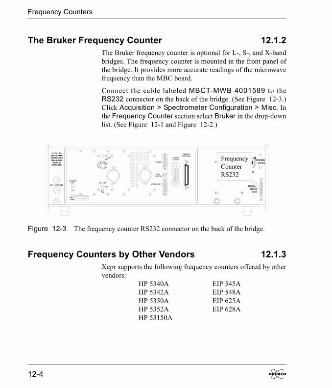
Frequency Counters
The Bruker Frequency Counter 12.1.2The Bruker frequency counter is optional for L-, S-, and X-bandbridges. The frequency counter is mounted in the front panel ofthe bridge. It provides more accurate readings of the microwavefrequency than the MBC board.
Connect the cable labeled MBCT-MWB 4001589 to theRS232 connector on the back of the bridge. (See Figure 12-3.)Click Acquisition > Spectrometer Configuration > Misc. Inthe Frequency Counter section select Bruker in the drop-downlist. (See Figure 12-1 and Figure 12-2.)
Frequency Counters by Other Vendors 12.1.3Xepr supports the following frequency counters offered by othervendors:
HP 5340A EIP 545AHP 5342A EIP 548AHP 5350A EIP 625AHP 5352A EIP 628AHP 53150A
Figure 12-3 The frequency counter RS232 connector on the back of the bridge.
FrequencyCounterRS232
12-4
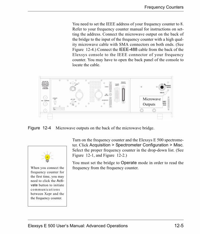
Frequency Counters
You need to set the IEEE address of your frequency counter to 8.Refer to your frequency counter manual for instructions on set-ting the address. Connect the microwave output on the back ofthe bridge to the input of the frequency counter with a high qual-ity microwave cable with SMA connectors on both ends. (SeeFigure 12-4.) Connect the IEEE-488 cable from the back of theElexsys console to the IEEE connector of your frequencycounter. You may have to open the back panel of the console tolocate the cable.
Turn on the frequency counter and the Elexsys E 500 spectrome-ter. Click Acquisition > Spectrometer Configuration > Misc.Select the proper frequency counter in the drop-down list. (SeeFigure 12-1, and Figure 12-2.)
You must set the bridge to Operate mode in order to read thefrequency from the frequency counter.
Figure 12-4 Microwave outputs on the back of the microwave bridge.
MicrowaveOutputs
When you connect thefrequency counter forthe first time, you mayneed to click the Acti-vate button to initiateco m m un i c a t i o n sbetween Xepr and thethe frequency counter.
Elexsys E 500 User�s Manual: Advanced Operations 12-5
ER 41X1VT Variable Temperature Systems
ER 41X1VT Variable Temperature Systems12.2These variable temperature systems are used for liquid nitrogenand above room temperature experiments. Refer to the manualsof your variable temperature unit for assembly and operationinstructions. In this section we provide instructions for connect-ing the temperature controller to the Elexsys E 500 spectrometerand configuring the Xepr software.
The X in the model number corresponds to the numbers one,two, or three. Xepr fully supports the newest temperature con-troller, BVT 3000 (ER 4131 VT). The older BVT 2000(ER 4121 VT) and BVT 1000 (ER 4111 VT) temperature con-trollers are only partially supported. The following stepsdescribe connecting and configuring the controller.
1. Connect the RS 232 cable. (For ER 4131VT andER 4121VT systems.) Open the front door of the con-sole. Use the RS 232 cable to connect the RS 232 connec-tor of the BVT temperature controller to the RS2connector of the ACPU board in the Elexsys console.(See Figure 12-5.)
2. Connect the Slow Device Bus cable. (ForER 4111VT systems only.) Open the front door of theconsole. Connect the COMPUTER connector on theBVT 1000 temperature controller to the SLD connectoron the SIP board of the acquisition server using a 25 pinSlow Device Bus cable. (See Figure 12-5.)
Th es e un i t s a r eoptional accessoriesand you may or maynot have ordered them.If you require an acces-sory, contact your localBruker EPR sales rep-resenta tive for pur-chase information.
12-6

ER 41X1VT Variable Temperature Sys-
3. Configure the temperature controller. Turn on thetemperature controller and the spectrometer. Connect tothe spectrometer. Click Acquisition > SpectrometerConfiguration > Misc. Select the variable temperaturesystem you are using in the Type drop-down list. ClickApply. If you plan on using the temperature controller inthe future, click Save. Then click Close to close the dia-log box. (See Figure 12-6.)
Figure 12-5 Connecting the RS 232 cable to the console.
RS2Connector
SLDConnector
Elexsys E 500 User�s Manual: Advanced Operations 12-7
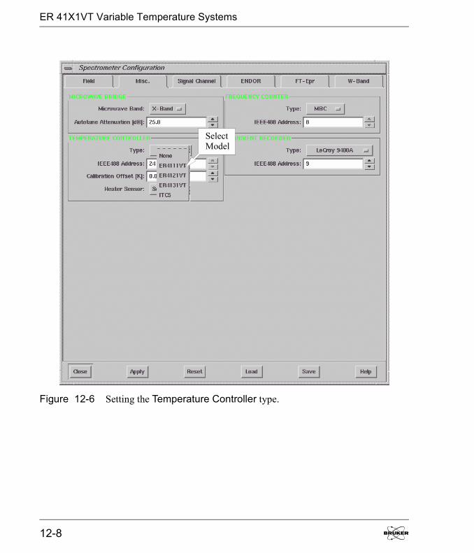
ER 41X1VT Variable Temperature Systems
Figure 12-6 Setting the Temperature Controller type.
SelectModel
12-8

ER 41X1VT Variable Temperature Sys-
4. Define an experiment that uses the temperaturecontroller. Create a new experiment with the Temp.Unit button activated (green). (See Figure 12-7.) Openthe Acquisition Parameters dialog box where you willfind the VTU folder. This folder allows you to set the tem-perature after you click the Activate button. For theER 4131 VT controller there is another sub-folder thatgives you remote control of many controller parameterssuch as gas flow and N2 evaporator boiler power. (See theER 4131 VT User �s manual for detai ls . ) For theER 4121 VT and ER 4111 VT controllers you can set thetemperature but you need to manually control other con-troller operating parameters.
Figure 12-7 Defining an experiment using a temperaturecontroller.
Consult the documen-t a t i on fo r t heER 4131VT to learnmore details about itsoperation.
Elexsys E 500 User�s Manual: Advanced Operations 12-9

ER 4112HV Variable Temperature Systems
ER 4112HV Variable Temperature Systems12.3The Bruker Elexsys E 500 series spectrometers support theER 4112HV temperature controller unit for liquid helium. In thissection we provide instructions for connecting the ITC 503 tem-perature controller to the Elexsys E 500 spectrometer and con-figuring the Xepr software. It is assumed that you are alreadyfamiliar with the operation of the temperature controller. If not,consult the Oxford Instruments documentation.
Setting the Controller Up 12.3.11. Connect the controller to the console. Connect the
IEEE 488 cable from the back of the spectrometer con-sole to the IEEE 488 connector of your ITC 503 tempera-ture controller. You may have to open the back panel ofthe console to locate the cable.
2. Connect to the spectrometer. Turn on the spectrom-eter and the ITC 503 temperature controller. After theacquisition server is booted, connect to the spectrometer.
3. Set the IEEE address. Click Acquisition > Spec-trometer Configuration > Misc. In the Type drop-downlist, select ITC 5 for your temperature controller. Thedefault IEEE address is 24 for both the temperature con-troller and the Xepr software.
4. Enter the temperature offset. If you have carefullycalibrated the temperature difference between the sampleand the temperature sensor, you can enter this temperatureoffset in the Calibration Offset box.
This unit is an optionalaccessory and you mayo r m ay n o t h av eo rd er ed i t . I f y o urequire an accessory,co n t a c t y o u r l oc a lBruker EPR sales rep-resenta tive for pur-chase information.
Consult the documen-t a t i on fo r t heER 4112HV to learnmore details about itsassembly and opera-tion.
12-10

ER 4112HV Variable Temperature Sys-
The Calibration Offset equals:
Calibration Offset = Tactual - TITC [12-2]
where Tactual is the actual temperature at the sample andTITC is the temperature measured with the cryostat tem-perature sensor.
5. Select a sensor. In the Heater Sensor section selectthe temperature sensor you are using on the ITC 503 con-troller to control the sample temperature. Unless you havemultiple helium cryostats in your lab, you usually shouldselect Sensor 1. Click Apply. If you plan on using thetemperature controller in the future, click Save. Thenclick Close to close the dialog box. (See Figure 12-8.)
Figure 12-8 Configuring the ITC 503 temperature controller.
Elexsys E 500 User�s Manual: Advanced Operations 12-11
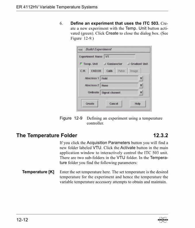
ER 4112HV Variable Temperature Systems
6. Define an experiment that uses the ITC 503. Cre-ate a new experiment with the Temp. Unit button acti-vated (green). Click Create to close the dialog box. (SeeFigure 12-9.)
The Temperature Folder 12.3.2If you click the Acquisition Parameters button you will find anew folder labeled VTU. Click the Activate button in the mainapplication window to interactively control the ITC 503 unit.There are two sub-folders in the VTU folder. In the Tempera-ture folder you find the following parameters:
Temperature [K] Enter the set temperature here. The set temperature is the desiredtemperature for the experiment and hence the temperature thevariable temperature accessory attempts to obtain and maintain.
Figure 12-9 Defining an experiment using a temperaturecontroller.
12-12
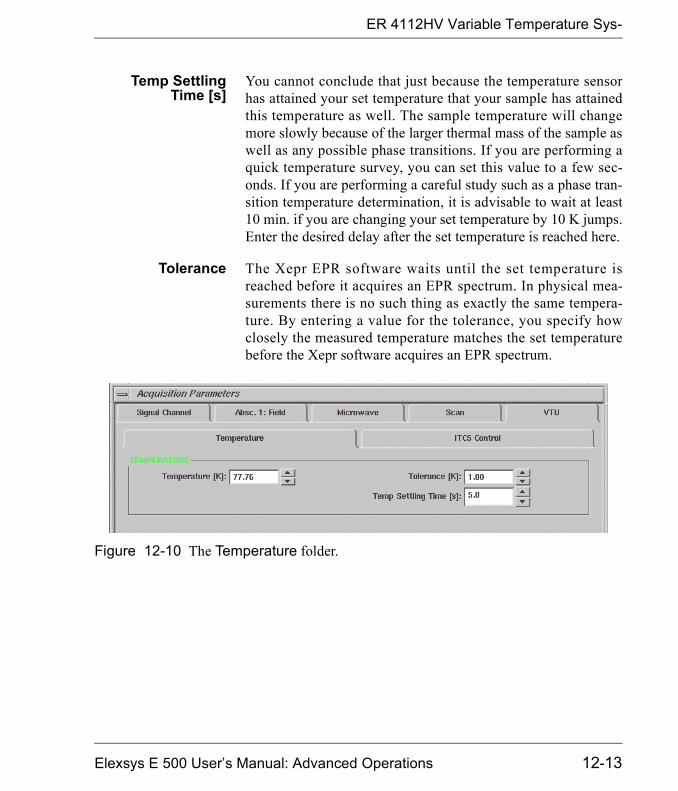
ER 4112HV Variable Temperature Sys-
Temp SettlingTime [s]
You cannot conclude that just because the temperature sensorhas attained your set temperature that your sample has attainedthis temperature as well. The sample temperature will changemore slowly because of the larger thermal mass of the sample aswell as any possible phase transitions. If you are performing aquick temperature survey, you can set this value to a few sec-onds. If you are performing a careful study such as a phase tran-sition temperature determination, it is advisable to wait at least10 min. if you are changing your set temperature by 10 K jumps.Enter the desired delay after the set temperature is reached here.
Tolerance The Xepr EPR software waits until the set temperature isreached before it acquires an EPR spectrum. In physical mea-surements there is no such thing as exactly the same tempera-ture. By entering a value for the tolerance, you specify howclosely the measured temperature matches the set temperaturebefore the Xepr software acquires an EPR spectrum.
Figure 12-10 The Temperature folder.
Elexsys E 500 User�s Manual: Advanced Operations 12-13
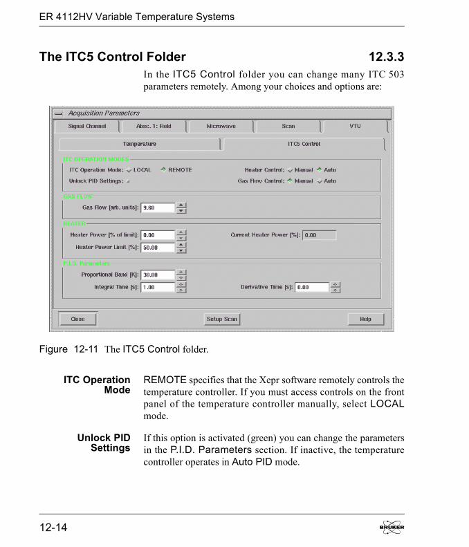
ER 4112HV Variable Temperature Systems
The ITC5 Control Folder 12.3.3In the ITC5 Control folder you can change many ITC 503parameters remotely. Among your choices and options are:
ITC OperationMode
REMOTE specifies that the Xepr software remotely controls thetemperature controller. If you must access controls on the frontpanel of the temperature controller manually, select LOCALmode.
Unlock PIDSettings
If this option is activated (green) you can change the parametersin the P.I.D. Parameters section. If inactive, the temperaturecontroller operates in Auto PID mode.
Figure 12-11 The ITC5 Control folder.
12-14

ER 4112HV Variable Temperature Sys-
Heater Control In Auto mode, the temperature controller stabilizes the tempera-ture at the set temperature by controlling the Heater Powerautomatically. Under some unusual circumstances you may needto specify a constant Heater Power value. Select Manual modeto manually control the Heater Power.
Gas Flow Control If you have a transfer line with a motorized needle valve, thetemperature controller can automatically control the cryogenflow when Auto mode is selected. Normally, you should selectManual mode to adjust the Gas Flow manually and let theheater stabilize the temperature first. Once a stable temperaturewith Auto Heater Control is reached, you can activate AutoGas Flow Control. If you initially set both Gas Flow Controland Heater Control to Auto mode at the same time, the two reg-ulation loops can fight each other, causing wild temperatureoscillations.
Gas Flow If you selected Manual Gas Flow Control mode, you canchange the needle valve position here. Zero corresponds to fullyclosed and 99.9 corresponds to fully open. Note that the flowdoes not vary linearly with needle valve position. If you selectedAuto mode, the current needle valve position is displayed.
Heater Power[% of limit]
If you selected Manual Heater Control mode, you can changethe Heater Power here. Zero corresponds to no power and 100corresponds to full power. If you selected Auto mode, the dis-play is grayed out.
Heater PowerLimit[%]
The Heater Power Limit allows you to limit the amount ofpower applied to the heater. 100% corresponds to 40 V. Thisvalue should be set to 87.5% for all Helium variable temperaturecontrollers in order to operate at the standard 35 V heater limit.
Current HeaterPower[%]
The Current Heater Power is displayed here.
Elexsys E 500 User�s Manual: Advanced Operations 12-15

ER 4112HV Variable Temperature Systems
Normally you should run experiments using Auto PID mode.Under some circumstances, you may need to change the PIDvalues.
Proportional The Proportional term corresponds to the reciprocal of the feed-back gain. Consult your cryostat data sheet in the cryostat man-ual for the appropriate value for your set temperature. You needto activate (green) the Unlock PID Settings button in ITCOperation Modes to make any changes in this parameter.
Integral The Integral term corresponds to the time constant of the feed-back loop. Consult your cryostat data sheet in the cryostat man-ual for the appropriate value for your set temperature. You needto activate (green) the Unlock PID Settings button in ITCOperation Modes to make any changes in this parameter.
Derivative The Derivative term controls the response of the controller torapid changes in temperature. Consult your cryostat data sheet inthe cryostat manual for the appropriate value for your set tem-perature. You need to activate (green) the Unlock PID Settingsbutton in ITC Operation Modes to make any changes in thisparameter.
There is a Temperature box in the Monitoring Panel whichdisplays the current temperature. It turns to green when the mea-sured temperature reaches the set temperature within the speci-fied tolerance. There are built-in 2D experiments available in theNew Experiments for your variable temperature studies.
12-16
The E 033M Field Frequency Lock
The E 033M Field Frequency Lock 12.4If you have warmed up your spectrometer sufficiently, you canusually perform stable field sweep experiments. Sometimes themicrowave frequency can drift owing to a number of externalinfluences. For example, sample heating can occur at highmicrowave (or RF in ENDOR experiments) power levels. Withvery long data acquisitions, the room temperature and hence thecavity frequency can change. Frequency drift results in drift ofthe apparent field for resonance owing to the Zeeman effect.
This drift affects two different classes of experiments. In staticmagnetic field experiments such as ENDOR or time sweeps inwhich you set your magnetic field to a specific point in yourEPR signal, you will drift away from that specific point, result-ing in baseline distortions and changing intensities. In magneticfield sweep experiments requiring signal averaging of weak andparticularly narrow signals, the frequency drift produces abroadening or smearing of the EPR lines.
The FF-Lock (Field-Frequency Lock) unit corrects for thesedrifts by locking to an external g = 2 EPR standard. As themicrowave frequency changes, the FF-Lock adjusts the mag-netic field to keep the EPR standard in resonance. In order to sta-bilize at fields where g ��2 or to perform field sweeps, there area set of offset coils on the FF-Lock probe. By changing the mag-netic field offset at the probe, we change the magnetic fieldvalue at which the FF-Lock locks the magnetic field. TheFF-Lock has a total operating range of 120 Gauss, i.e. ± 60 Geither side of g=2.0.
This unit is an optionalaccessory and you mayo r m ay n o t h av eo rd er ed i t . I f y o urequire an accessory,co n t a c t y o u r l oc a lBruker EPR sales rep-resenta tive for pur-chase information.
Elexsys E 500 User�s Manual: Advanced Operations 12-17
The E 033M Field Frequency Lock
Installing an FF-Lock 12.4.1If the FF-Lock is not currently installed in your console, youneed to follow the instructions in this section.
1. Install the FF-Lock probe head. Follow the instruc-tions of the FF-Lock manual to mount the FF-Lock probehead and connect the semi-rigid cable to the microwavebridge.
2. Remove the blank panel. Open the front door of theElexsys console. Remove the blank panel under themicrowave bridge controller of the console. There are twopanels. You can use whichever one is available.
3. Install the FF-Lock unit into the console. Align theFF-Lock unit to the support brackets in the console andslide it in. Secure the unit with the mounting screws.
4. Change the ER 032 T cable connections. Open theback door of the console. There is a cable labeledER 032 T connected to the 5 pin connector on the back oft h e f i e l d c o n t r o l l e r. ( S e e t h e d o t t e d a r r o w i nFigure 12-12.) Disconnect the cable and reconnect it tothe MAG. OUT 5 pin connector on the back of theFF-Lock. (See Figure 12-12.)
12-18

The E 033M Field Frequency Lock
5. Connect MAG. IN to the field controller. Usinganother 5 pin cable connect the MAG. IN signal of theFF-Lock to the 5 pin connector on the back of the fieldcontroller where the ER 032 T cable was connected.
6. Connect the sweep address cable. Use the 15 pinribbon cable to connect SWA OUT of the field controllerto SWA IN of the FF-Lock. (See Figure 12-12.)
Figure 12-12 Back view of the FF-Lock (above) and field controller (below).
MAG.OUT
MAG.IN
SWAIN
SWAOUT
5 PinCable
15 PinRibbonCable
5 PinCable
Elexsys E 500 User�s Manual: Advanced Operations 12-19

The E 033M Field Frequency Lock
7. Connect the power supply cable. Locate theFF-Lock Burndy cable from the power rack on the back ofthe console. Connect it to the Burndy connector on theback of the FF-Lock. (See Figure 12-13.)
8. Connect the IEC 625 cable. There is an IEC 625cable connected to the front of the GSI board of the acqui-sition server. Connect the other end to the IEC 625 con-nector on the back of the FF-Lock. (See Figure 12-13.)
9. Connect the FF-Lock probe head. There are twocables coming out of the FF-Lock probe head. The Modu-lation/Sweep cable (triax) needs to be connected toMOD OUT on the back of the FF-Lock. The Signal cable(coax) needs to be connected to SIG IN on the back of theFF-Lock. (See Figure 12-13.)
Figure 12-13 Back view of the FF-Lock.
BurndyConnector
IEC 625MODOUT
SIG.IN
IEEE 488Address
Connector
Consult the FF-Lockdocumentation for fur-ther details.
12-20
The E 033M Field Frequency Lock
10. Check the IEEE 488 address. The default IEEE 488address is three. The DIP switches for setting the addressdefine a binary number. Therefore three corresponds toswitches 1 and 2 on. Switches 6 and 7 should be on forproper communication. All other switches should be off.The switches are rocker switches and on corresponds tohaving the upper part pressed in. (See Figure 12-13.)
11. Configure the FF-Lock. Follow the instructions inSection 4.1 to configure the FF-Lock.
Using the FF-Lock in Lock-in Mode 12.4.2The lock-in mode of the FF-Lock allows you to keep an EPRsignal in resonance despite shifts in frequency. It also allows youto perform stable field-sweeps over very long periods of time inwhich the microwave frequency can drift.
1. Get ready for using the FF-Lock. Set the microwavebridge controller to Operate mode.
2. Define a field sweep experiment. 3. Select the center field and sweep width. As men-
tioned in the introduction the FF-Lock can lock over a± 60 G range centered at g = 2. Set the center field valueto a value that corresponds to g = 2 at your microwave fre-quency. Set the sweep width to less than 120 G. To ensurethat we can lock the FF-Lock, set the current magneticfield to the center field value.
4. Open the FF-Lock/Teslameter dialog box. Clickthe FF-Lock/Teslameter button and open the dialog box.(See Figure 12-14.)
The FF-Loc k on lyworks at X-band.
Elexsys E 500 User�s Manual: Advanced Operations 12-21
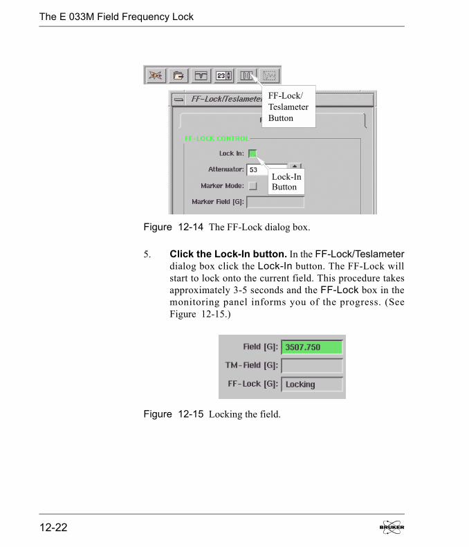
The E 033M Field Frequency Lock
5. Click the Lock-In button. In the FF-Lock/Teslameterdialog box click the Lock-In button. The FF-Lock willstart to lock onto the current field. This procedure takesapproximately 3-5 seconds and the FF-Lock box in themonitoring panel informs you of the progress. (SeeFigure 12-15.)
Figure 12-14 The FF-Lock dialog box.
Figure 12-15 Locking the field.
FF-Lock/TeslameterButton
Lock-InButton
12-22

The E 033M Field Frequency Lock
During the locking process the FF-Lock finds the mag-netic field offset (produced by the offset coils) required tobring the internal g=2 standard in resonance. This valueappears in the FF-Lock [G] display of the monitoringpanel. It corresponds to the difference between the presentmagnetic field and the field for resonance of the g = 2standard. This value will change as you sweep the field.(See Figure 12-16.)
6. Sweep the field with the FF-Lock. When the Lock-Inprocedure has been successfully completed, the FF-Lockthen takes over control of the field from the Hall fieldcontroller after you click the Run button. The FF-Locknow controls both the Center Field and the SweepWidth. Once the FF-Lock is locked, all acquisitionparameters, including the field sweep parameters, may bechanged without unlocking it first.
Figure 12-16 The magnetic field offset of the FF-Lock.
Elexsys E 500 User�s Manual: Advanced Operations 12-23

The E 033M Field Frequency Lock
Troubleshooting Locking Problems 12.4.3If the Lock-In procedure is unsuccessful after its fifth attempt,an error message appears in the FF-Lock window. (SeeFigure 12-17.)
If this happens, check if:
� The magnetic field is in the locking range of the FF-Lock(± 60 G centered at g = 2).
� The microwave bridge is not in STAND BY mode.
� The SMA connectors on the semi-rigid microwave cable aresufficiently tight. (Do not over-tighten them!)
If for any reason the FF-Lock should lose its lock during anacquisition, the message �Lost Lock� will be displayed in theFF-Lock box of the monitoring panel. (See Figure 12-18.)
Figure 12-17 Failure to lock the field.
Figure 12-18 Lost lock.
12-24
The E 033M Field Frequency Lock
Then the field control is automatically transferred back to theHall field controller until the FF-Lock catches up of its ownaccord, or is locked in again. If this happens, the acquired datawill have to be discarded.
The FF-Lock has a total operating range of 120 Gauss, i.e.± 60 G either side of g=2.0. Hence if the field sweep is centeredat g=2.0, the maximum sweep width is 120 G. The further awaythe center field is from g=2.0, the smaller the maximum possiblesweep becomes. The maximum sweep width (in Gauss) is givenby the formula:
SWMax = 2 * (60 - |OF|) [12-3]
where OF is the difference between the center field and the mag-netic field where g=2.0. If the presently set sweep width andcenter field exceed this limit, an appropriate error message isdisplayed.
Elexsys E 500 User�s Manual: Advanced Operations 12-25
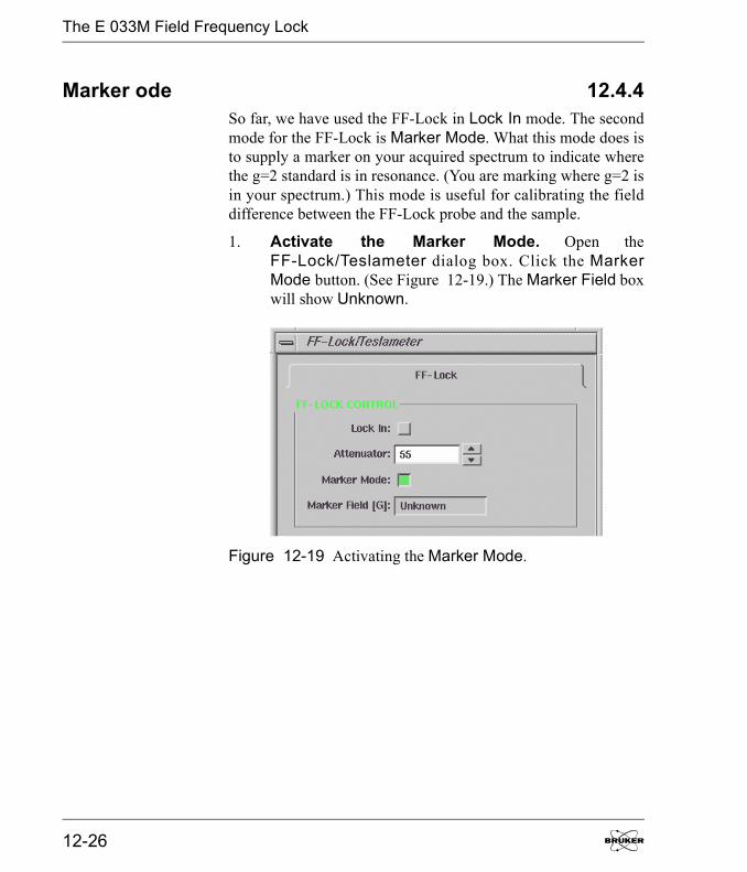
The E 033M Field Frequency Lock
Marker ode 12.4.4So far, we have used the FF-Lock in Lock In mode. The secondmode for the FF-Lock is Marker Mode. What this mode does isto supply a marker on your acquired spectrum to indicate wherethe g=2 standard is in resonance. (You are marking where g=2 isin your spectrum.) This mode is useful for calibrating the fielddifference between the FF-Lock probe and the sample.
1. Activate the Marker Mode. Open theFF-Lock/Teslameter dialog box. Click the MarkerMode button. (See Figure 12-19.) The Marker Field boxwill show Unknown.
Figure 12-19 Activating the Marker Mode.
12-26
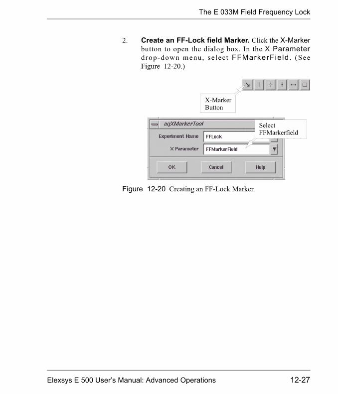
The E 033M Field Frequency Lock
2. Create an FF-Lock field Marker. Click the X-Markerbutton to open the dialog box. In the X Parameterdrop-down menu, se lec t FFMarkerF ie ld . (SeeFigure 12-20.)
Figure 12-20 Creating an FF-Lock Marker.
X-MarkerButton
SelectFFMarkerfield
Elexsys E 500 User�s Manual: Advanced Operations 12-27
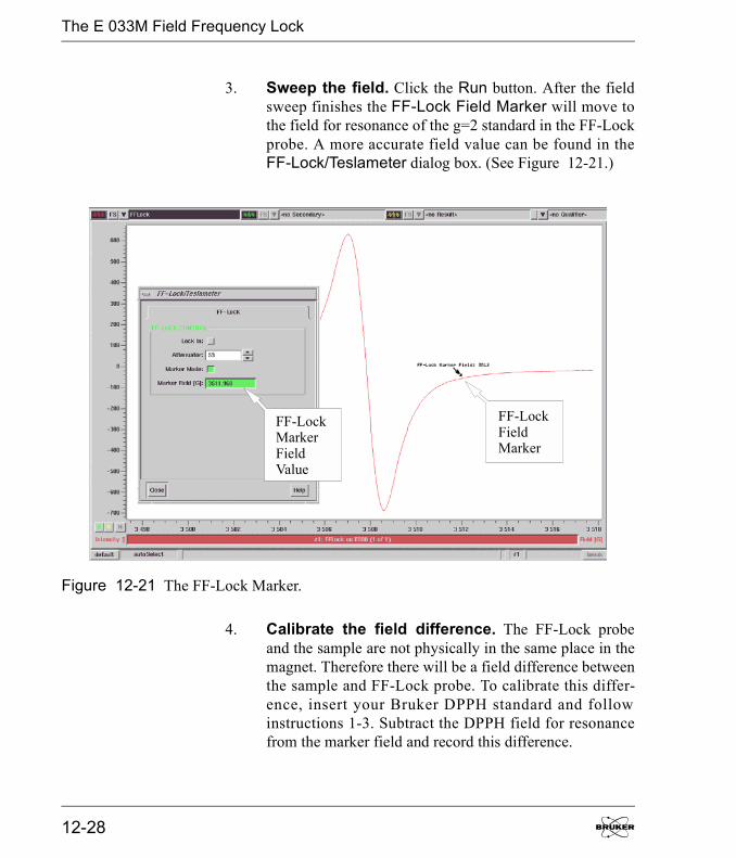
The E 033M Field Frequency Lock
3. Sweep the field. Click the Run button. After the fieldsweep finishes the FF-Lock Field Marker will move tothe field for resonance of the g=2 standard in the FF-Lockprobe. A more accurate field value can be found in theFF-Lock/Teslameter dialog box. (See Figure 12-21.)
4. Calibrate the field difference. The FF-Lock probeand the sample are not physically in the same place in themagnet. Therefore there will be a field difference betweenthe sample and FF-Lock probe. To calibrate this differ-ence, insert your Bruker DPPH standard and followinstructions 1-3. Subtract the DPPH field for resonancefrom the marker field and record this difference.
Figure 12-21 The FF-Lock Marker.
FF-LockFieldMarker
FF-LockMarkerFieldValue
12-28
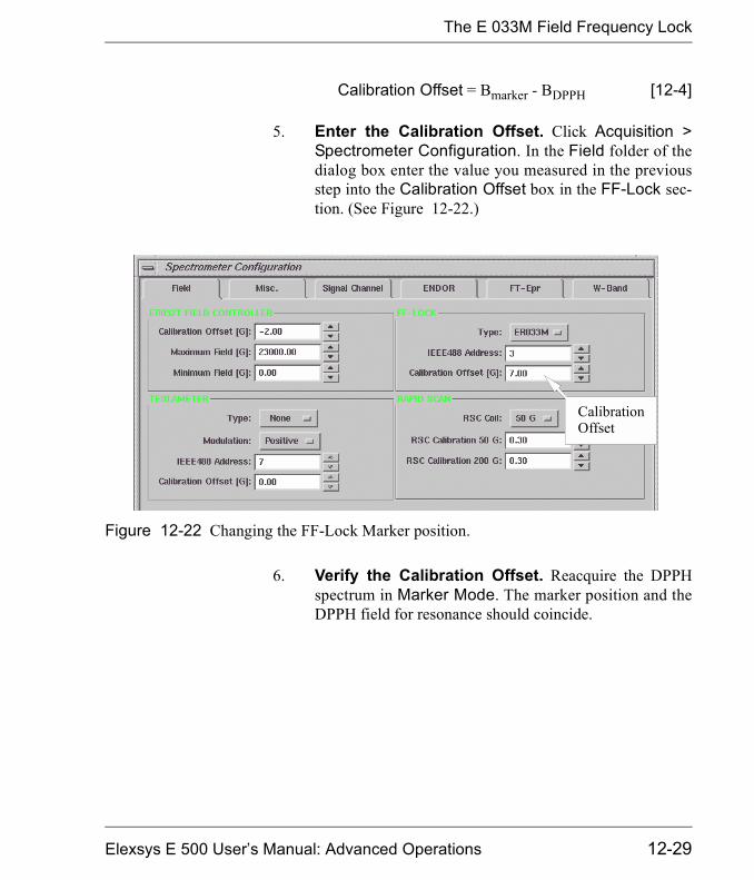
The E 033M Field Frequency Lock
Calibration Offset = Bmarker - BDPPH [12-4]
5. Enter the Calibration Offset. Click Acquisition >Spectrometer Configuration. In the Field folder of thedialog box enter the value you measured in the previousstep into the Calibration Offset box in the FF-Lock sec-tion. (See Figure 12-22.)
6. Verify the Calibration Offset. Reacquire the DPPHspectrum in Marker Mode. The marker position and theDPPH field for resonance should coincide.
Figure 12-22 Changing the FF-Lock Marker position.
CalibrationOffset
Elexsys E 500 User�s Manual: Advanced Operations 12-29

The E 033M Field Frequency Lock
Out of Locking Range Errors 12.4.5If you set the field position or the Calibration Offset out of thelocking range you will receive a �No Resonance� error mes-sage in the FF-Lock/Teslameter dialog box. (See Figure 12-23.)Reset the magnetic field position to remedy this error.
Figure 12-23 The No Resonance error message.
12-30
The E 035M Teslameter
The E 035M Teslameter 12.5The Bruker E 035M teslameter (gaussmeter) is designed for pre-cisely measuring the magnetic field B0 and uses the protonnuclear magnetic resonance frequency to measure the magneticfield. Since the resonant frequency can be measured precisely,the resulting resolution of the magnetic field value can be 1 mil-ligauss. This section describes how to connect it to the Elexsysconsole as well as how to use it with the Xepr software.
Installing a Teslameter 12.5.11. Mount the teslameter probe. Follow the instructions
of the teslameter manual to mount the teslameter probe.Select the probe that covers the field range at which youare working.
2. Remove the blank panel. Open the front door of theElexsys console. Remove the blank dummy panel underthe microwave bridge controller of the console. There aretwo panels. You can use whichever one is available.
3. Install the teslameter unit into the console. Alignthe teslameter unit to the support brackets in the consoleand slide it in. Secure the unit with the mounting screws.
4. Connect the teslameter cable. Use the connectingcable to connect the teslameter probe to the teslametercable connector on the rear panel of the teslameter unit.(See Figure 12-24.)
This unit is an optionalaccessory and you mayo r m ay n o t h av eo rd er ed i t . I f y o urequire an accessory,co n t a c t y o u r l oc a lBruker EPR sales rep-resenta tive for pur-chase information.
Consult the teslameterdocumentation for fur-ther details.
Elexsys E 500 User�s Manual: Advanced Operations 12-31
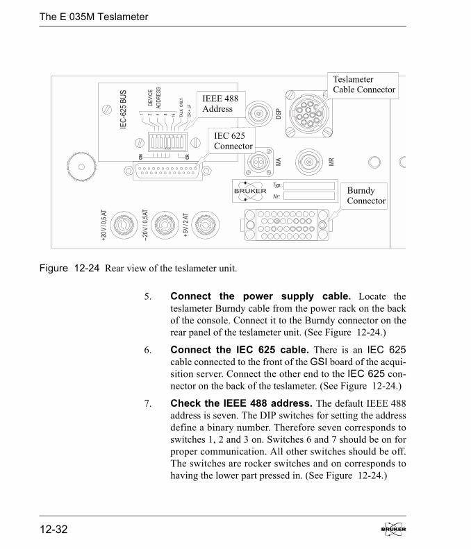
The E 035M Teslameter
5. Connect the power supply cable. Locate theteslameter Burndy cable from the power rack on the backof the console. Connect it to the Burndy connector on therear panel of the teslameter unit. (See Figure 12-24.)
6. Connect the IEC 625 cable. There is an IEC 625cable connected to the front of the GSI board of the acqui-sition server. Connect the other end to the IEC 625 con-nector on the back of the teslameter. (See Figure 12-24.)
7. Check the IEEE 488 address. The default IEEE 488address is seven. The DIP switches for setting the addressdefine a binary number. Therefore seven corresponds toswitches 1, 2 and 3 on. Switches 6 and 7 should be on forproper communication. All other switches should be off.The switches are rocker switches and on corresponds tohaving the lower part pressed in. (See Figure 12-24.)
Figure 12-24 Rear view of the teslameter unit.
TeslameterCable Connector
BurndyConnector
IEC 625Connector
IEEE 488Address
12-32

The E 035M Teslameter
8. Configure the teslameter. Follow the instructions inSection 4.1 to configure the teslameter.
Using the Teslameter 12.5.21. Define a field sweep experiment. Create a field
sweep experiment. Before you activate the teslameter,acquire a spectrum. Center the spectrum and adjust theparameters.
2. Open the FF-Lock/Teslameter dialog box. Clickthe FF-Lock/Teslameter button in the experiment toolbar to open the dialog box. (See Figure 12-25.)
3. Activate the teslameter. Click the Standard Controltab. Select the Lock Resolution from the drop-down list.We recommend that you start with low resolution e.g.0.1 G and increase the resolution after the teslameter findsthe field. Click the Use Teslameter button to activate it.The teslameter will start to search for the current fieldposition. (See Figure 12-26.)
Figure 12-25 The FF-Lock/Teslameter button.
FF-Lock/TeslameterButton
Elexsys E 500 User�s Manual: Advanced Operations 12-33
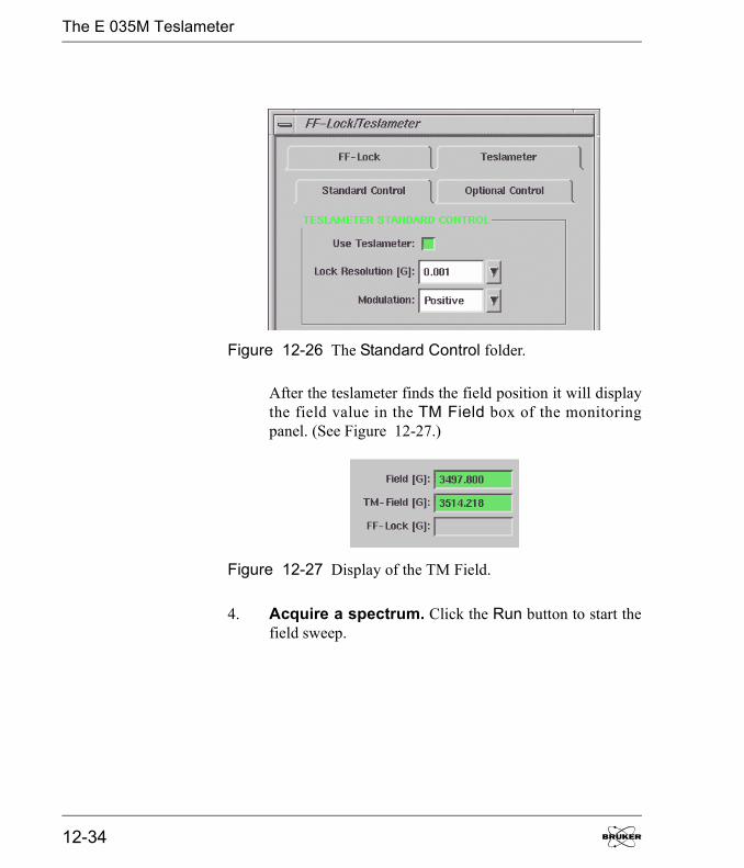
The E 035M Teslameter
After the teslameter finds the field position it will displaythe field value in the TM Field box of the monitoringpanel. (See Figure 12-27.)
4. Acquire a spectrum. Click the Run button to start thefield sweep.
Figure 12-26 The Standard Control folder.
Figure 12-27 Display of the TM Field.
12-34
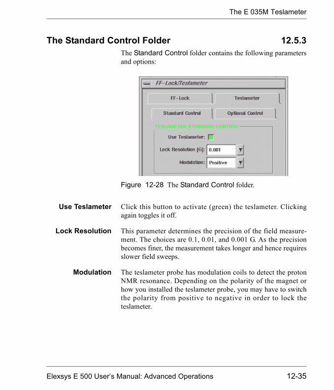
The E 035M Teslameter
The Standard Control Folder 12.5.3The Standard Control folder contains the following parametersand options:
Use Teslameter Click this button to activate (green) the teslameter. Clickingagain toggles it off.
Lock Resolution This parameter determines the precision of the field measure-ment. The choices are 0.1, 0.01, and 0.001 G. As the precisionbecomes finer, the measurement takes longer and hence requiresslower field sweeps.
Modulation The teslameter probe has modulation coils to detect the protonNMR resonance. Depending on the polarity of the magnet orhow you installed the teslameter probe, you may have to switchthe polarity from positive to negative in order to lock theteslameter.
Figure 12-28 The Standard Control folder.
Elexsys E 500 User�s Manual: Advanced Operations 12-35

The E 035M Teslameter
The Optional Control Folder 12.5.4The Optional Control folder contains the following parametersand options:
Field SearchDirection
Before you can measure magnetic fields with the teslameter, themodule must first find the proton resonance. In order to expeditethe search for the signal, you can specify the direction of thesearch. For example, if you were originally at 3000 G and youhave changed your magnetic field to 4000, you should chooseUp as your search direction. Should you want to stop the searchfor the signal, click the Stop Search button.
Field SearchLimit [G]
In order to find the proton resonance more quickly, you may nar-row the search range. Enter appropriate values for Upper FieldSearch Limit and Lower Field Search Limit. Make sure thatthe search range covers the field your experiment defined anddoes not exceed the cover range of the probe you use. (SeeFigure 12-29.)
Figure 12-29 The Optional Control folder.
12-36
The E 035M Teslameter
Calibrating the Field Offset 12.5.5The teslameter measures the field value where the teslameterprobe is located. It could be slightly different from the field thatsample experiences because they are not physically in the sameposition. To correct the field value you can calibrate the teslame-ter by setting the Calibration Offset. There are two ways to cal-ibrate the field. You can either use a field marker or the optionalintra-cavity probe (E 035M-1009).
� Calibrate the field offset using the intra-cavityprobe. Follow the intra-cavity probe user�s manual forinstallation and operation. Record the intra-cavity probe(Bsample) and teslameter probe (Bteslameter) readings.
� Calibrate the field offset with a field marker. Insert afield marker sample to the cavity. Tune and match the cavity.Calculate the field value (Bsample) by using the known g-fac-tor of the field marker and the microwave frequency.
. [12-5]
Record this value as well as the field value for the g-valuestandard read by the teslameter (Bteslameter).
The Calibration Offset equals:
Calibration Offset = Bsample - Bteslameter , [12-6]
where Bsample is the field measured with the intra-cavity probeor g-value standard and Bteslameter is the field read by theteslameter. In the Teslameter section of the Field folder enterthe difference into the Calibration Offset. Click Apply andclose the Spectrometer Configuration dialog box.
Open the Spectrometer Configuration dialog box.
Bsample 714.4775 �
g---�=
Elexsys E 500 User�s Manual: Advanced Operations 12-37

The E 035M Teslameter
If you calibrate the field offset of the field controller at the sametime and enter the difference in the Field Offset in the Spec-trometer Configuration dialog box, you may use the centerfield tool with the teslameter activated.
Troubleshooting 12.5.6If the teslameter cannot find the field position or it keeps search-ing for a long time the modulation may have the wrong phase.Deactivate the teslameter by clicking the Stop Search button inthe Optional Control folder. Select Negative from the Modula-tion drop-down list in the Standard Control folder. Press theUse Teslameter button again.
The field values of spectra acquired with the teslameter are theteslameter�s readings. You may have problems using the acquisi-tion tools such as the Center Field tool or the Center Field &Sweep Width tool. This is because the tool�s readings are thoseof the teslameter�s. What is actually required by the field con-troller to center the spectrum are the values measured by the hallprobe. To solve this problem you can either set the center fieldbefore activating the teslameter or calibrate both the teslameterand the Field Offset of the field controller. Refer to Chapter 5and the previous section for the calibration process.
12-38
The ER 218PG1 Goniometer
The ER 218PG1 Goniometer 12.6A goniometer is a necessity when the EPR signal of a sample isorientationly dependent such as single crystals or other orderedsamples. Xepr can control the programmable goniometer fromthe software. This section provides you step-by-step instructionson how to use a Bruker programmable goniometer with theElexsys E 500 spectrometer.
Installing a Programmable Goniometer 12.6.1Please refer to the Programmable Goniometer ER 218PG1User�s Manual for how to install a goniometer. There are twocables you must connect to the Elexsys console.
1. Connect the Slow Device Bus cable. Open the frontdoor of the console. Connect the Slow Device Bus con-nector (25 pin) on the goniometer electronic box mountedon the magnet to the SLD connector on the SIP board ofthe acquisition server using a 25 pin Slow Device Buscable. (See Figure 12-30.)
2. Connect the power supply cable. Locate the Burndycable labeled Goniometer from the power rack on theback of the console. You may have to open the back of theconsole to locate the cable. Connect it to the power supplyBurndy cable of the goniometer control unit
This unit is an optionalaccessory and you mayo r m ay n o t h av eo rd er ed i t . I f y o urequire an accessory,co n t a c t y o u r l oc a lBruker EPR sales rep-resenta tive for pur-chase information.
Elexsys E 500 User�s Manual: Advanced Operations 12-39

The ER 218PG1 Goniometer
Configuring the Goniometer 12.6.21. Define a goniometer experiment. Open the New
Experiment dialog box. Click the Goniometer button toactivate it. If you want to acquire a 2D spectra you canselect Sample angle (Goniometer) in the Abscissa 2drop-down list. Click Create to close the dialog box. (SeeFigure 12-31.)
Figure 12-30 Connecting the control cable.
SIPboard
SLDconnector
12-40
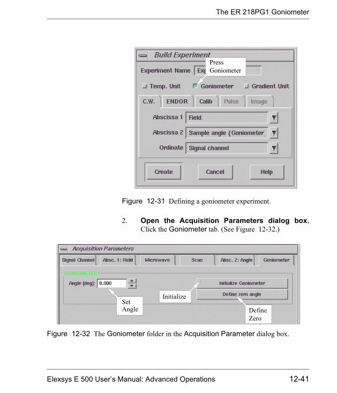
The ER 218PG1 Goniometer
2. Open the Acquisition Parameters dialog box.Click the Goniometer tab. (See Figure 12-32.)
Figure 12-31 Defining a goniometer experiment.
PressGoniometer
Figure 12-32 The Goniometer folder in the Acquisition Parameter dialog box.
Initialize
DefineZero
SetAngle
Elexsys E 500 User�s Manual: Advanced Operations 12-41

The ER 218PG1 Goniometer
3. Initialize the goniometer. Make sure the shaft is inplace. Click the Activate button. Click the InitializeGoniometer button in the Goniometer folder. The soft-ware will search for the 0 notch on the goniometer andin i t i a l ize tha t po in t as the �home� po in t . (SeeFigure 12-32.) Meanwhile the angle display in the moni-to r ing pane l w i l l tu rn f rom red to g reen . (SeeFigure 12-33.)
4. Define the zero angle. You can define any angle to bethe new zero, regardless of the present goniometer angle.Click the Define Zero Angle button to set the currentsample angle as the new zero.
5. Set the angle. Enter a value in the Angle box. The goni-ometer will turn to that angle.
Figure 12-33 The goniometer angle display.
12-42

The ER 218PG1 Goniometer
6. Set up for a 2D experiment. If you create a 2D exper-iment you can set the angle range and angle increment inthe Absc. 2: Angle folder. (See Figure 12-34.)
Select Each Slice Scan for Acq Fine Tuning parameterin the Microwave folder. The acquisition software willperform a fine tune before acquiring each slice of the 2Dspectrum. This option is particularly important becausechanging the orientation of the sample with a programma-
Figure 12-34 Setup for a 2D spectra using the programmable goniometer.
Elexsys E 500 User�s Manual: Advanced Operations 12-43
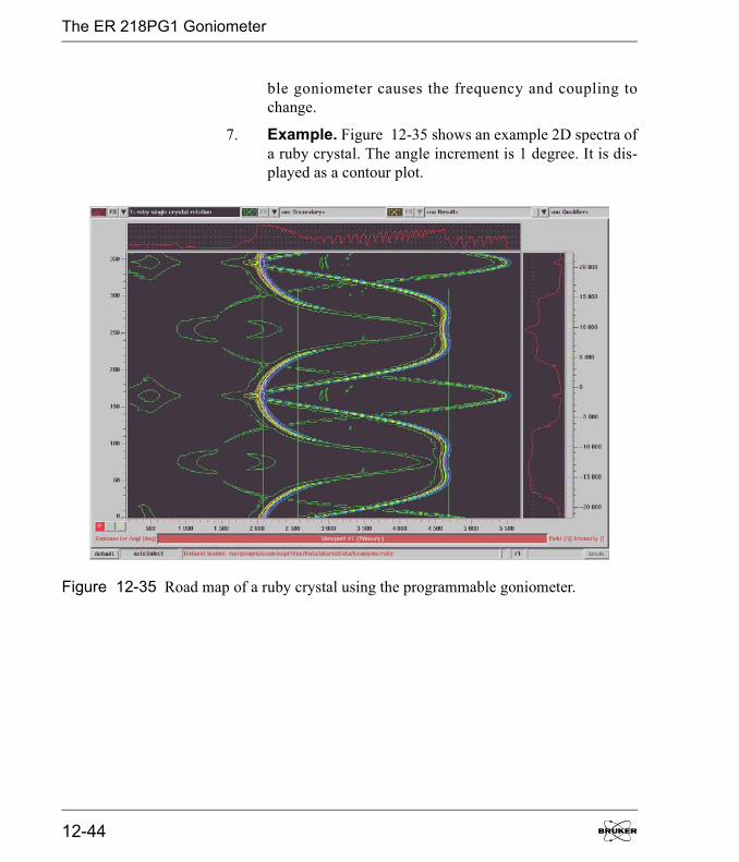
The ER 218PG1 Goniometer
ble goniometer causes the frequency and coupling tochange.
7. Example. Figure 12-35 shows an example 2D spectra ofa ruby crystal. The angle increment is 1 degree. It is dis-played as a contour plot.
Figure 12-35 Road map of a ruby crystal using the programmable goniometer.
12-44

Wiring and Configuration 13This chapter describes the connectors on the front panel of manyof the modules and boards in the console. It also guides youthrough configuring the signal paths using the software.
Console Module Arrangement 13.1
Figure 13-1 Console module arrangement.
Optional NMR Teslameter
Optional Field- Frequency Lock
Modulation Amplifier
Ventilator
Field Controller
SCT/L
Computer Rack
Ventilator
ADF RSC
Microwave Bridge Controller
SCT-PS
HCPU
Optional ENDOR Unit
SCT/H
Elexsys E 500 User�s Manual: Advanced Operations
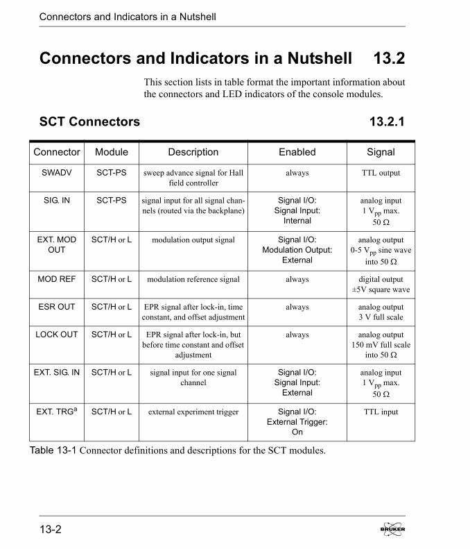
Connectors and Indicators in a Nutshell
T
Connectors and Indicators in a Nutshell 13.2This section lists in table format the important information aboutthe connectors and LED indicators of the console modules.
SCT Connectors 13.2.1
Connector Module Description Enabled Signal
SWADV SCT-PS sweep advance signal for Hall field controller
always TTL output
SIG. IN SCT-PS signal input for all signal chan-nels (routed via the backplane)
Signal I/O:Signal Input:
Internal
analog input1 Vpp max.
50 �
EXT. MOD OUT
SCT/H or L modulation output signal Signal I/O:Modulation Output:
External
analog output0-5 Vpp sine wave
into 50 �
MOD REF SCT/H or L modulation reference signal always digital output±5V square wave
ESR OUT SCT/H or L EPR signal after lock-in, time constant, and offset adjustment
always analog output3 V full scale
LOCK OUT SCT/H or L EPR signal after lock-in, but before time constant and offset
adjustment
always analog output150 mV full scale
into 50 �
EXT. SIG. IN SCT/H or L signal input for one signal channel
Signal I/O:Signal Input:
External
analog input1 Vpp max.
50 �
EXT. TRGa SCT/H or L external experiment trigger Signal I/O:External Trigger:
On
TTL input
able 13-1 Connector definitions and descriptions for the SCT modules.
13-2

Connectors and Indicators in a Nutshell
T
EXT. TRGb SCT/H or L external lock-in frequency Signal I/O:External Lock In:
On
TTL input
EXT. MOD. IN
Mod.Amplifier external modulation input Signal I/O:Modulation Input:
External
analog input10 Vpp max.
RS IN Mod.Amplifier rapid scan input Rapid Scanexperiment
analog inputramp 5 Vpp max.
RESONA-TOR 1
Mod.Amplifier 1st resonator modulationoutput
Signal I/O:Resonator: 1
analog output300 Vpp sine wave
max.
RESONA-TOR 2
Mod.Amplifier 2nd resonator modulationoutput
Signal I/O:Resonator: 2
analog output300 Vpp sine wave
max.
RS OUT50 G
Mod.Amplifier 50 G rapid scan coil output Spectrometer Configuration: Field: RSC Coil: 50 G& Rapid Scan experiment
analog output30 Vpp ramp max.
RS OUT200 G
Mod.Amplifier 200 G rapid scan coil output Spectrometer Configuration: Field: RSC Coil:
200 G& Rapid Scan experiment
analog output30 Vpp ramp max.
Connector Module Description Enabled Signal
able 13-1 Connector definitions and descriptions for the SCT modules.
Elexsys E 500 User�s Manual: Advanced Operations 13-3

Connectors and Indicators in a Nutshell
SCT LED Indicators 13.2.2
Indicator Module Color Indication
+15 V SCT-PS green +15 V present
-15 V SCT-PS green -15 V present
+5 V SCT-PS green +5 V present
TEMP SCT-PS red temperature fault
R SCT/H or L green transputer software loaded
A SCT/H or L green unit is acquiring spectra
Q SCT/H or L green quadrature detection
E SCT/H or L red transputer error
O SCT/H or L red AC overflow
M SCT/H or L red modulation overload
Table 13-2 Indicator definitions and descriptions for the SCT modules.
13-4
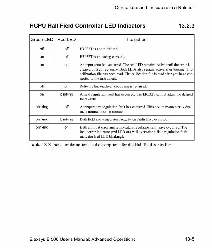
Connectors and Indicators in a Nutshell
HCPU Hall Field Controller LED Indicators 13.2.3
Green LED Red LED Indication
off off ER032T is not initialized.
on off ER032T is operating correctly.
on on An input error has occurred. The red LED remains active until the error is cleared by a correct entry. Both LEDs also remain active after booting if no calibration file has been read. The calibration file is read after you have con-nected to the instrument.
off on Software has crashed. Rebooting is required.
on blinking A field regulation fault has occurred. The ER032T cannot attain the desired field value.
blinking off A temperature regulation fault has occurred. This occurs momentarily dur-ing a normal booting process.
blinking blinking Both field and temperature regulation faults have occurred.
blinking on Both an input error and temperature regulation fault have occurred. The input error indicator (red LED on) will overwrite a field regulation fault indicator (red LED blinking).
Table 13-3 Indicator definitions and descriptions for the Hall field controller
Elexsys E 500 User�s Manual: Advanced Operations 13-5
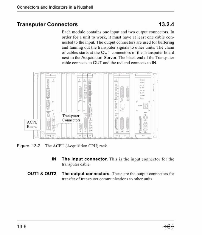
Connectors and Indicators in a Nutshell
Transputer Connectors 13.2.4Each module contains one input and two output connectors. Inorder for a unit to work, it must have at least one cable con-nected to the input. The output connectors are used for bufferingand fanning out the transputer signals to other units. The chainof cables starts at the OUT connectors of the Transputer boardnext to the Acquisition Server. The black end of the Transputercable connects to OUT and the red end connects to IN.
IN The input connector. This is the input connector for thetransputer cable.
OUT1 & OUT2 The output connectors. These are the output connectors fortransfer of transputer communications to other units.
Figure 13-2 The ACPU (Acquisition CPU) rack.
ACPUBoard
TransputerConnectors
13-6

Connectors and Indicators in a Nutshell
A typical t ransputer cable configurat ion is shown inFigure 13-4.
Figure 13-3 The Transputer connectors of the HCPUboard.
Figure 13-4 Transputer cable configuration for an E 500spectrometer.
TransputerConnectors
Elexsys E 500 User�s Manual: Advanced Operations 13-7
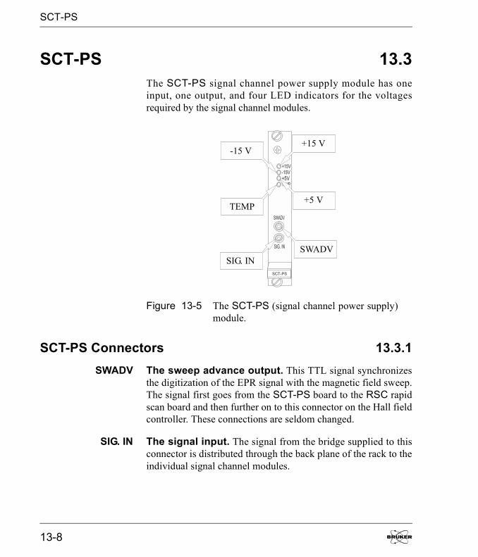
SCT-PS
SCT-PS 13.3The SCT-PS signal channel power supply module has oneinput, one output, and four LED indicators for the voltagesrequired by the signal channel modules.
SCT-PS Connectors 13.3.1SWADV The sweep advance output. This TTL signal synchronizes
the digitization of the EPR signal with the magnetic field sweep.The signal first goes from the SCT-PS board to the RSC rapidscan board and then further on to this connector on the Hall fieldcontroller. These connections are seldom changed.
SIG. IN The signal input. The signal from the bridge supplied to thisconnector is distributed through the back plane of the rack to theindividual signal channel modules.
Figure 13-5 The SCT-PS (signal channel power supply)module.
+15 V-15 V
+5 VTEMP
SWADVSIG. IN
13-8
SCT-PS
SCT-PS Indicators 13.3.2+15 V The +15 V indicator. Normally this indicator is green, mean-
ing +15 volts is supplied to the signal channel.
-15 V The -15 V indicator. When this indicator is green, -15 volts issupplied to the signal channel.
+5 V The +5 V indicator. When this indicator is green, +5 volts issupplied to the signal channel.
TEMP The temperature fault indicator. Under normal conditionsthis indicator is off. If this indicator turns to red a temperaturefault exists. The console may be overheated. Check if the fanson the back panel are on. Check the filters of the ventilator unitsand clean them if they are dirty. If all else fails, contact yourlocal Bruker EPR service representative for help.
Elexsys E 500 User�s Manual: Advanced Operations 13-9
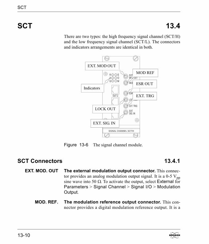
SCT
SCT 13.4There are two types: the high frequency signal channel (SCT/H)and the low frequency signal channel (SCT/L). The connectorsand indicators arrangements are identical in both.
SCT Connectors 13.4.1EXT. MOD. OUT The external modulation output connector. This connec-
tor provides an analog modulation output signal. It is a 0-5 Vppsine wave into 50 �. To activate the output, select External forParameters > Signal Channel > Signal I/O > ModulationOutput.
MOD. REF. The modulation reference output connector. This con-nector provides a digital modulation reference output. It is a
Figure 13-6 The signal channel module.
MOD REF
EXT. MOD OUT
Indicators ESR OUT
LOCK OUT
EXT. TRG
EXT. SIG. IN
13-10

SCT
±5 V square wave signal with a frequency equal to the modula-tion frequency. It is always enabled.
ESR OUT The EPR signal output connector. This is an analog EPRsignal output. Full scale corresponds to 3 V into 50 �. The signalis obtained after the lock-in amplifier, time constant filter, andDC offset adjustment and just before the digitizer. It is alwaysenabled.
LOCK OUT The unfiltered EPR output connector. This is also an ana-log EPR signal output. Full scale corresponds to 150 mV into50 �. LOCK OUT differs from ESR OUT in that the signal isobtained after the lock-in amplifier but before the time constantfilter and the DC offset adjustment. It is always enabled. It ismost often used in double modulation experiments.
EXT. SIG. IN The external signal input connector. Normally, the signalchannel obtains its signal from the SIG. IN connector of theSCT-PS via the back plane of the rack. This connector isdesigned for external signal input into individual signal chan-nels. It accepts a 1 Vpp maximum analog signal and the imped-ance is 50 ohm. To enable external signal input, select Externalfor Parameters > Signal Channel > Signal I/O > SignalInput.
EXT. TRG The external trigger input connector. The signal appliedto this connector can perform two different and mutually exclu-sive functions. The first function of the connector is as an exter-nal trigger input to start an acquisition. It requires a TTL levelsignal (> 2V) to trigger the acquisition. To enable the externaltrigger function, click the External Trigger button (until it isgreen or active) in Parameters > Signal Channel > SignalI/O.
The second function for this input is as an external modulationreference for demodulating the EPR signal. It requires a TTLlevel square wave signal (> 2V) with the same frequency as the
Elexsys E 500 User�s Manual: Advanced Operations 13-11

SCT
modulation frequency. To enable the external modulation refer-ence function, click the External Lock In button (until it isgreen or active) in Parameters > Signal Channel > SignalI/O.
TransputerConnectors
See Section 13.2.4.
SCT Indicators 13.4.2R The ready LED. The LED blinks when the transputer software
is loading. It remains a steady green when the signal channel isready for acquiring a signal. If this led is not on after you turn onthe console there may be a problem with booting the signalchannel transputer.
A The acquisition LED. When an acquisition with this signalchannel is in progress, this LED is lit.
Q The quadrature LED. When a quadrature detection acquisi-tion is in progress, this LED is lit, indicating that two signalchannels are acquiring in parallel.
E The error LED. It indicates a transputer error when lit.
O The overload LED. This indicator lights when there is an ACoverflow. Turn down the receiver gain, microwave power, orreduce the AFC gain if this occurs.
M The modulation overload LED. This indicator lights whenthe modulation amplifier is overdriven. Turn down the modula-tion amplitude if this occurs.
13-12
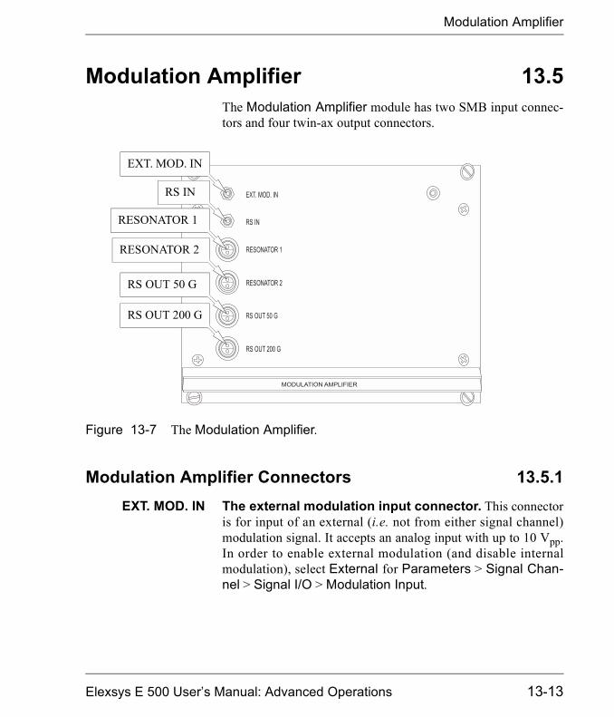
Modulation Amplifier
Modulation Amplifier 13.5The Modulation Amplifier module has two SMB input connec-tors and four twin-ax output connectors.
Modulation Amplifier Connectors 13.5.1EXT. MOD. IN The external modulation input connector. This connector
is for input of an external (i.e. not from either signal channel)modulation signal. It accepts an analog input with up to 10 Vpp.In order to enable external modulation (and disable internalmodulation), select External for Parameters > Signal Chan-nel > Signal I/O > Modulation Input.
Figure 13-7 The Modulation Amplifier.
EXT. MOD. IN
RS IN
RESONATOR 1
RESONATOR 2
RS OUT 50 G
RS OUT 200 G
Elexsys E 500 User�s Manual: Advanced Operations 13-13
Modulation Amplifier
RS IN The rapid scan input connector. This connector is for inputof the rapid scan ramp. It accepts an analog input of a maximum5 volt ramp. It is enabled whenever a rapid scan experiment isactive. The RSC cable is normally attached to this connector.
RESONATOR 1 The first modulation output connector. This connectorprovides the modulation output for the first resonator. It is ananalog sine wave output supplying up to 300 Vpp. It is activatedby selecting 1 for Parameters > Signal Channel > Signal I/O> Resonator.
RESONATOR 2 The second modulation output connector. This connec-tor is similar to RESONATOR 1 except it is for RESONATOR2 and is used for the second set of modulation coils for theER 4114DR dual resonator. The two outputs cannot be usedsimultaneously. To enable RESONATOR 2, select 2 forParameters > Signal Channel > Signal I/O > Resonator.
RS OUT 50 G The 50 G rapid scan output connector. This is the rapidscan ramp output for the 50 G rapid scan coil. It supplies an ana-log ramp output with up to 30 Vpp. To activate it, create a rapidscan experiment and select 50 G for Acquisition > Spectrome-ter Configuration > Field > RSC Coil.
RS OUT 200 G The 200 G rapid scan output connector. This is the rapidscan ramp output for the 200 G rapid scan coil. It supplies ananalog ramp output with up to 30 Vpp. To activate it, create arapid scan experiment and select 200 G for Acquisition >Spectrometer Configuration > Field > RSC Coil.
13-14

HCPU
HCPU 13.6The HCPU Hall controller power unit has two LEDs, theSWADV connector, and three transputer connectors.
HCPU Indicators 13.6.1Green & Red LED The status indicator LEDs. The meaning of the green and
red LEDs is somewhat complicated. Refer to Table 13-3 forcomplete definitions.
HCPU Connectors 13.6.2SWADV The sweep address advance input. This TTL signal syn-
chronizes the digitization of the EPR signal with the magneticfield sweep. The signal first goes from the SCT-PS board to the
Figure 13-8 The HCPU.
Red LED
SWADV
Green LED
TransputerConnectors
Elexsys E 500 User�s Manual: Advanced Operations 13-15

HCPU
RSC rapid scan board and then further on to this connector onthe Hall field controller. These connections are seldom changed.
TransputerConnectors
See Section 13.2.4.
13-16

ADF
ADF 13.7The ADF is a fast digitizer board. It has three LED indicatorsand three connectors.
ADF Indicators 13.7.1READY The ready LED. This green LED indicates that the ADF board
is ready. When the console is turned on this LED should be lit.
Figure 13-9 The ADF board.
AIConnector
ClockOut
AUXConnector
Indicator forEXT. TRG
ConvertingIndicator
READYLED
Elexsys E 500 User�s Manual: Advanced Operations 13-17
ADF
T The external trigger LED. When this yellow LED is on itindicates that the ADF is using an external trigger.
C The converting LED. This indicates that the ADF is digitizingdata.
ADF Connectors 13.7.2CLK OUT The clock out connector. This connector supplies the TTL
clock signal from the ADF.
AUX The auxiliary connector. This is a 25 pin connector. The pinout is shown in Figure 13-10. Most of the pins are specificallyreserved for spectrometer operation and are not available forgeneral use. The pins available to users are highlighted inFigure 13-10. The most important is pin 5, the external triggerinput. There is a cable labeled TRIGGER connected to this pin.You can use it to externally trigger the ADF with a TTL levelpulse. To enable the external trigger, select External Sweep forParameters > Fast Digitizer > Trigger Mode. In the TriggerSlope drop-down menu in the same menu, you must also selectwhether the rising or falling edge triggers the acquisition. If yourspectrometer is equipped with an optional ENDOR unit, theTrigger cable should be connected to the T connector of the EIFboard.
13-18

ADF
AI The analog input connector. The AI connector has two dif-ferential input pairs for the signal to be digitized. The first pair isreserved for digitizing the EPR signal. It connects to the ESROUT connector of the signal channel in the standard configura-tion. It is referred to as Channel A. The second pair can be usedto digitize other signals. There is a cable connected to the secondchannel (Channel B) labeled as ADF ENDOR. If you have an
Figure 13-10 The ADF board AUX connector pin layout.
1 PP 0 (in/out)
2 PP 2 (in/out)
3 ADV (out)
4 BUSY (out)
5 EXTRG (in)5 EXTRG (in)
6 MODOUT (out)
7 PP 3 (in/out)
8 PP 4 (in/out)
9 nc
10 nc
11 nc
12 nc
13 SWEND (out)
PP 1 (in/out) 14
GND 15GND 15
GND 16GND 16
GND 17GND 17
GND 18GND 18
GND 19GND 19
+5 Volt (fused/out) 20+5 Volt (fused/out) 20
+5 Volt (fused/out) 21+5 Volt (fused/out) 21
PP 5 (in/out) 22
PP 6 (in/out) 23
PP 7 (in/out) 24
ACK (in) 25
Elexsys E 500 User�s Manual: Advanced Operations 13-19

ADF
optional ENDOR unit, it is connected to the ADF connector ofthe DICE box. The center conductor is the non-inverting inputand the shield is the inverting input. The impedance of the inputsis 200 �. The voltage range is ±2.5 V full scale. For a pin-out seeFigure 13-11.
There are options for digitizing either Channel A or B or bothchannels. For a rapid field scan experiment, select A, B or A&Bfor Parameters > Field > Rapid Scan Options > InputMode. For a rapid time sweep, select the appropriate values forParameters > Fast Digitizer > Input Mode.
Figure 13-11 The ADF board AI connector pin layout.
1 +15 Volt (fused)
2 Analog inp. 2 (noninv.)
3 GND
4 Analog inp. 1 (noninv.)
5 Analog inp. 1 (inv.)
-15 Volt (fused) 6
Analog inp. 2 (inv.) 7
GND 8
GND 9
13-20

RSC
RSC 13.8The RSC (Rapid Scan Controller) board is essentially a pro-grammable ramp generator. It supplies the signal that is ampli-fied by the modulation amplifier. This board is used inconjunction with the ADF board to acquire field sweep signalsrapidly. It has four indicators and seven connectors.
RSC Indicators 13.8.1READY The ready LED. This LED is the ready indicator for the RSC
board. It is lit after the first time you initiate the rapid scan func-tion.
S The sweep LED. This LED indicates a rapid field sweep isactive.
T The trigger LED. This LED indicates the RSC board is readyfor a trigger.
M The modulation overload LED. This LED indicates that themodulation amplifier (that supplies the current to the rapid scancoils) is overloaded.
RSC Connectors 13.8.2RSC The rapid scan output. This is the rapid scan voltage output.
It is an analog signal ranging ± 1 V into 50 � and drives themodulation amplifier through its RS connector.
10 MHz The external clock input. This connector allows you to inputan external 10 MHz TTL external clock signal.
ZPH The zero phase output. This connector supplies a 50 �s neg-ative TTL pulse upon the start of the rapid scan ramp�This pulseis useful for synchronizing other events with the sweep.
Elexsys E 500 User�s Manual: Advanced Operations 13-21
RSC
MOD IN The modulation input. An external modulation signal sup-plied here simply goes out the MOD OUT connector.
MOD OUT The modulation output. The signal supplied to the MOD INconnector comes out of this connector.
TRG The trigger input. The RSC board can be triggered by anexternal signal (generated by an external event such as a laserpulse) applied to this input. The board is triggered by the fallingedge of a TTL level signal. (Note that this can be inverted byusing jumper J8 on the RSC board.)
I/O The input/output connector. This connector is reserved foruse by Bruker.
13-22
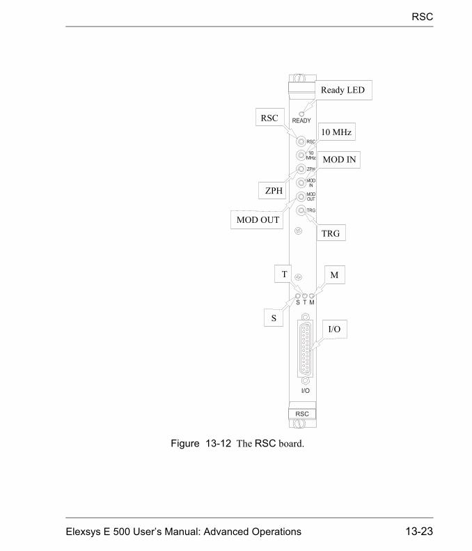
RSC
Figure 13-12 The RSC board.
Ready LED
RSC10 MHz
ZPH
MOD IN
MOD OUTTRG
T M
SI/O
Elexsys E 500 User�s Manual: Advanced Operations 13-23

RSC
13-24

Experiment Setup 14A standard Bruker Elexsys EPR spectrometer is equipped with ahigh frequency signal channel (6-100 kHz), low frequency sig-nal channel (100-10,000 Hz), and rapid digitizer (ADF) for per-forming routine field/time scan experiments. By rerouting thesignal paths using the inputs and outputs of the front panels ofthe modules and selecting options in the software, many customexperiments such as double modulation can be implemented.The previous chapter describes the connections, indicators, andparameters available to you for configuring your experiments.This chapter presents how to set up the experiments. StandardExperiments describes configuring experiments that do notrequire any wiring changes or extra components. Custom Exper-iments describes experiments that need extra wiring or devices.Figure 14-1 shows the symbols and figure legends used in thischapter.
Figure 14-1 A key to the symbol and figure legends.
Standard internal wiring (via backplane)
Standard external wiring (via cable)
Extra cable connections for specialExperiments
Trigger (rising edge)
Trigger (falling edge)
Elexsys E 500 User�s Manual: Advanced Operations
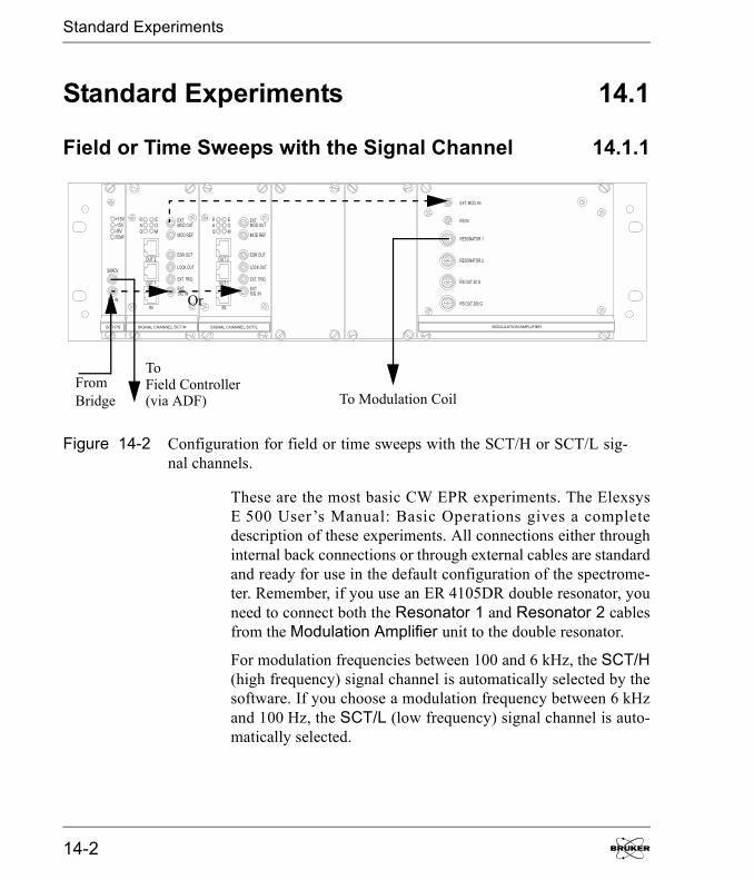
Standard Experiments
Standard Experiments 14.1
Field or Time Sweeps with the Signal Channel 14.1.1
These are the most basic CW EPR experiments. The ElexsysE 500 User�s Manual: Basic Operations gives a completedescription of these experiments. All connections either throughinternal back connections or through external cables are standardand ready for use in the default configuration of the spectrome-ter. Remember, if you use an ER 4105DR double resonator, youneed to connect both the Resonator 1 and Resonator 2 cablesfrom the Modulation Amplifier unit to the double resonator.
For modulation frequencies between 100 and 6 kHz, the SCT/H(high frequency) signal channel is automatically selected by thesoftware. If you choose a modulation frequency between 6 kHzand 100 Hz, the SCT/L (low frequency) signal channel is auto-matically selected.
Figure 14-2 Configuration for field or time sweeps with the SCT/H or SCT/L sig-nal channels.
FromBridge
ToField Controller(via ADF) To Modulation Coil
Or
14-2

Standard Experiments
Field or Time Sweeps with the Fast Digitizer (ADF) 14.1.2When the acquisition is shorter than 5 seconds, you should usethe fast digitizer (ADF) to acquire a field or time scan instead ofthe signal channel digitizer. A complete description of thisexperiment is given in Section 6.1 of this manual. All connec-tions either through internal back connections or through exter-nal cables are standard and ready for use in the defaultconfiguration of the spectrometer.
Figure 14-3 Configuration for field or time sweeps with the ADF.
Field Controller
ADF
To Modulation CoilsFromBridge
CH A
AUX
AI
SWADV
Elexsys E 500 User�s Manual: Advanced Operations 14-3

Standard Experiments
Rapid Field Scans with the Fast Digitizer (ADF) 14.1.3The combination of the ADF (fast digitizer) and RSC (RapidScan Controller) with rapid sweep coils provides a tool toacquire spectra of short lived species. A complete description ofthis experiment is given in Section 6.2 of this manual. All con-nections either through internal back connections or throughexternal cables are standard and ready for use in the default con-figuration of the spectrometer.
Figure 14-4 Configuration for rapid field scans with the ADF.
FieldADF
ToFromBridge
CH A
Controller
ModCoils
To
To200 GRSCoils
RSC
AI
AUX
RSC
SWADV
50 GRSCoils
14-4
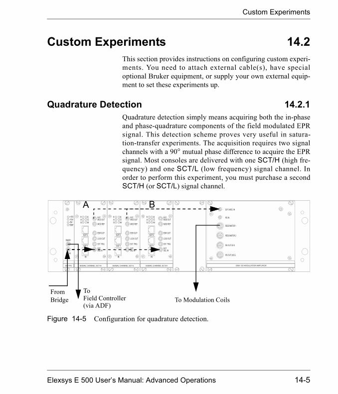
Custom Experiments
Custom Experiments 14.2This section provides instructions on configuring custom experi-ments. You need to attach external cable(s), have specialoptional Bruker equipment, or supply your own external equip-ment to set these experiments up.
Quadrature Detection 14.2.1Quadrature detection simply means acquiring both the in-phaseand phase-quadrature components of the field modulated EPRsignal. This detection scheme proves very useful in satura-tion-transfer experiments. The acquisition requires two signalchannels with a 90° mutual phase difference to acquire the EPRsignal. Most consoles are delivered with one SCT/H (high fre-quency) and one SCT/L (low frequency) signal channel. Inorder to perform this experiment, you must purchase a secondSCT/H (or SCT/L) signal channel.
Figure 14-5 Configuration for quadrature detection.
FromBridge
ToField Controller(via ADF)
To Modulation Coils
A B
Elexsys E 500 User�s Manual: Advanced Operations 14-5
Custom Experiments
It is assumed that you have already created a standard field ortime sweep experiment.
1. Install the second signal channel. Turn off the spec-trometer. Install a second SCT/H (high frequency) signalchannel, B, next to the SCT/L (low frequency) signalchannel. Connect a transputer cable from OUT2 of signalchannel A to IN on signal channel B. (See Figure 14-5.)Turn on the console and connect the workstation to thespectrometer.
2. Set up for quadrature detection. Open the Parame-ter dialog box and select the Signal Channel folder.Click the Detection tab and press the QuadratureDetection button. (See Figure 14-6.) Press the Activatebutton.
These instructions arefor modulation frequen-cies greater than 6 kHz.For lower frequencies,s imp ly subs t i t u t eSCT/L for SCT/H.
14-6
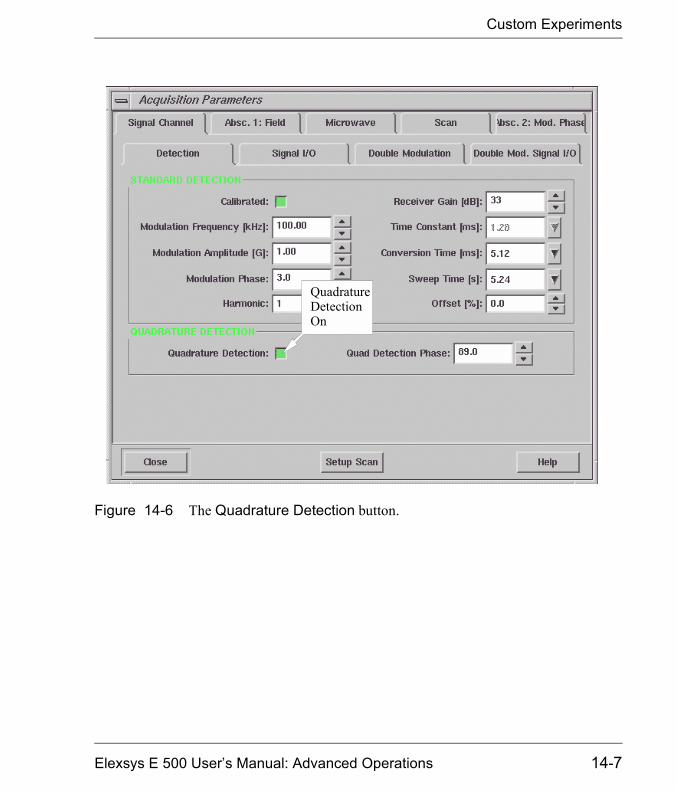
Custom Experiments
Figure 14-6 The Quadrature Detection button.
QuadratureDetectionOn
Elexsys E 500 User�s Manual: Advanced Operations 14-7
Custom Experiments
3. Check the phase of signal channel A. Although thephase of the signal channel A has been calibrated duringthe signal channel calibration it still could be a fewdegrees off. Moving a modulation cable can producephase shifts of a few degrees. Use a strong sample such asDPPH to check the phase. Change the ModulationPhase from 0° to 90° in the Signal Channel Detectionfolder. Adjust the Modulation Phase to minimize thesignal. It is convenient to monitor the signal with theSetup Scan feature. When the signal is minimized, shiftthe Modulation Phase by -90° to maximize the signal.
Pressing the <Ctrl> keyand clicking the up ord o wn a r ro w k e ychanges the phase by90°.
14-8

Custom Experiments
Figure 14-7 Calibrating the phase of signal channel A.
ModulationPhase
MinimizedSignal
Elexsys E 500 User�s Manual: Advanced Operations 14-9
Custom Experiments
4. Calibrate the phase of signal channel B. The phaseof the two signal channels might be slightly different.Therefore the phase difference may not be exactly 90°when you set the Quad Detection Phase to 90°. To cali-brate the difference, set the Quad Detection Phase to90°. Check if the signal from signal channel B is mini-mized. Adjust the Quad Detection Phase until the sig-nal from signal channel B is minimized. Using the SetupScan function helps you to interactively optimize thephase. You need to select A&B in the Setup Scan SCTdrop-down list to view signals from both signal channelssimultaneously.
When you calibrate thephase difference, uselow microwave powerto avoid saturating theEPR signal.
14-10

Custom Experiments
Figure 14-8 Calibrating the phase of signal channel B.
QuadDetectionPhase
SignalfromChannel A
SignalfromChannel B
SetupScanSCT
Elexsys E 500 User�s Manual: Advanced Operations 14-11

Custom Experiments
5. Acquire a quadrature spectrum. Click the Run but-ton to acquire a quadrature spectrum. The Q LED indica-tors on both signal channels should light up.
6. View the signals from both channels. The resultantspectrum is complex in which the real part is the signaldetected by the signal channel A and the imaginary part isthe signal detected by the signal channel B. Click theRe/Im button in the Tool bar to display the two signalsrespectively. (See Figure 14-9.)
Figure 14-9 Viewing the signals from both signal channels.
Real Partfrom A Imaginary
Part from B
14-12

Custom Experiments
Externally Triggered Sweeps with the Signal Channel 14.2.2If you need to synchronize an external event such as a lamp flashwith your EPR acquisition, you can trigger the acquisition exter-nally. This section describes how to trigger a field or time sweepusing the signal channel. It is assumed that you have already cre-ated a standard field or time sweep experiment.
1. Provide an external trigger. Connect an externalcable carrying a TTL (5 volt) positive-going trigger pulseto the EXT. TRIG connector of the signal channel. Takecare about the impedance, i.e. make sure the trigger volt-age is high enough after the cable is connected. Also notethat the acquisition is triggered by a rising slope.
2. Enable the external trigger in the software. Openthe Parameter dialog box and click the Signal Channeltab. Click the Signal I/O tab and then the External Trig-ger button to activate it (green).
Figure 14-10 Configuration for externally triggered sweeps with the signal channel.
FromBridge
ToField
(via ADF)To ModControllerCoils
TTL
EXT.TRIG
Elexsys E 500 User�s Manual: Advanced Operations 14-13
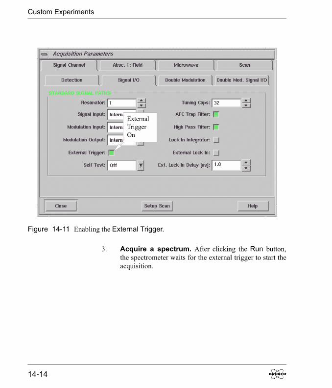
Custom Experiments
3. Acquire a spectrum. After clicking the Run button,the spectrometer waits for the external trigger to start theacquisition.
Figure 14-11 Enabling the External Trigger.
ExternalTriggerOn
14-14
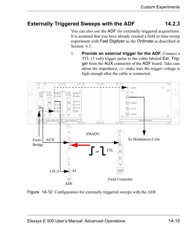
Custom Experiments
Externally Triggered Sweeps with the ADF 14.2.3You can also use the ADF for externally triggered acquisitions.It is assumed that you have already created a field or time sweepexperiment with Fast Digitizer as the Ordinate as described inSection 6.1.
1. Provide an external trigger for the ADF. Connect aTTL (5 volt) trigger pulse to the cable labeled Ext. Trig-ger from the AUX connector of the ADF board. Take careabout the impedance, i.e. make sure the trigger voltage ishigh enough after the cable is connected.
Figure 14-12 Configuration for externally triggered sweeps with the ADF.
Field ControllerADF
To Modulation CoilsFromBridge
CH A
TTLor
AUX
AI
SWADV
Elexsys E 500 User�s Manual: Advanced Operations 14-15
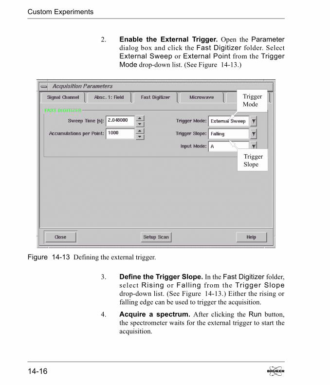
Custom Experiments
2. Enable the External Trigger. Open the Parameterdialog box and click the Fast Digitizer folder. SelectExternal Sweep or External Point from the TriggerMode drop-down list. (See Figure 14-13.)
3. Define the Trigger Slope. In the Fast Digitizer folder,select Rising or Falling from the Trigger Slopedrop-down list. (See Figure 14-13.) Either the rising orfalling edge can be used to trigger the acquisition.
4. Acquire a spectrum. After clicking the Run button,the spectrometer waits for the external trigger to start theacquisition.
Figure 14-13 Defining the external trigger.
TriggerMode
TriggerSlope
14-16
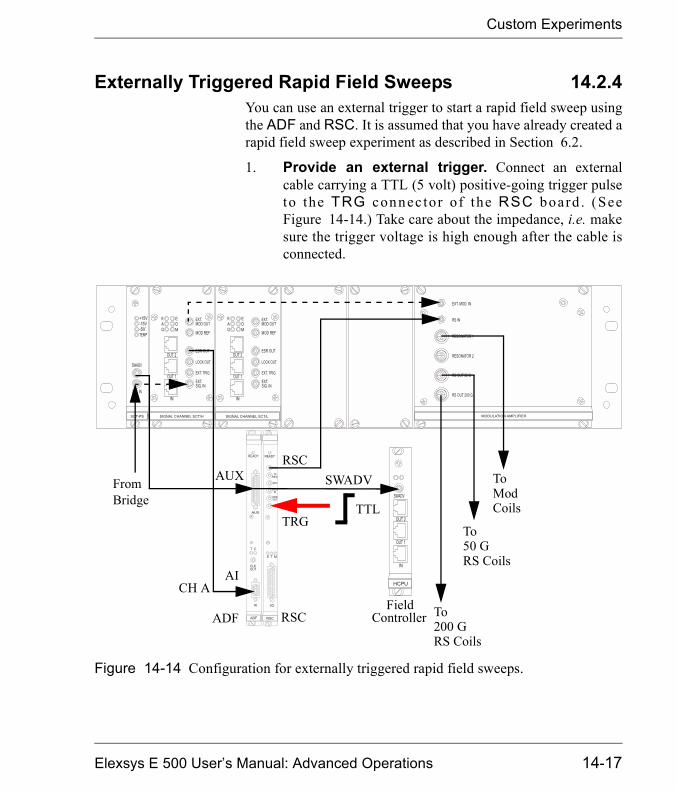
Custom Experiments
Externally Triggered Rapid Field Sweeps 14.2.4You can use an external trigger to start a rapid field sweep usingthe ADF and RSC. It is assumed that you have already created arapid field sweep experiment as described in Section 6.2.
1. Provide an external trigger. Connect an externalcable carrying a TTL (5 volt) positive-going trigger pulseto the TRG connec tor of the RSC board . (SeeFigure 14-14.) Take care about the impedance, i.e. makesure the trigger voltage is high enough after the cable isconnected.
Figure 14-14 Configuration for externally triggered rapid field sweeps.
FieldADF
ToFromBridge
CH A
Controller
ModCoils
To50 GRS Coils
To200 GRS Coils
RSC
TTLTRG
AI
AUX
RSC
SWADV
Elexsys E 500 User�s Manual: Advanced Operations 14-17
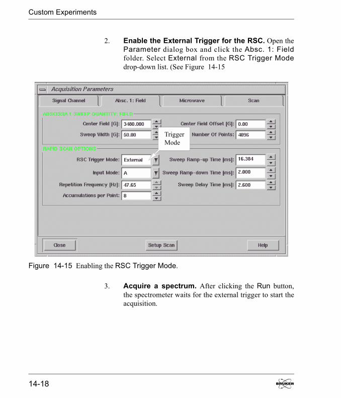
Custom Experiments
2. Enable the External Trigger for the RSC. Open theParameter dialog box and click the Absc. 1: Fieldfolder. Select External from the RSC Trigger Modedrop-down list. (See Figure 14-15
3. Acquire a spectrum. After clicking the Run button,the spectrometer waits for the external trigger to start theacquisition.
Figure 14-15 Enabling the RSC Trigger Mode.
TriggerMode
14-18
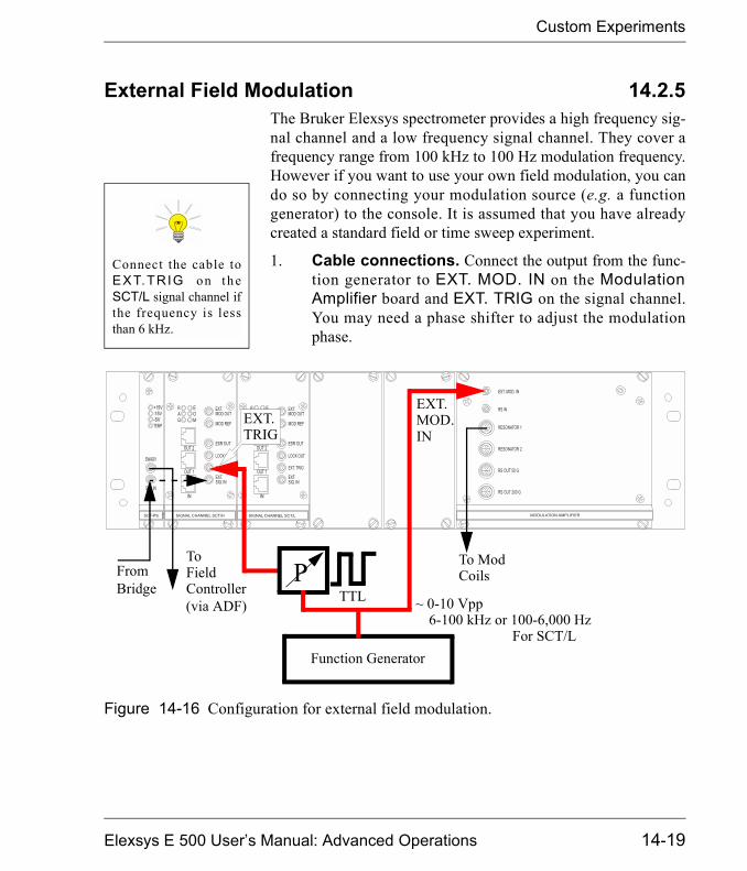
Custom Experiments
External Field Modulation 14.2.5The Bruker Elexsys spectrometer provides a high frequency sig-nal channel and a low frequency signal channel. They cover afrequency range from 100 kHz to 100 Hz modulation frequency.However if you want to use your own field modulation, you cando so by connecting your modulation source (e.g. a functiongenerator) to the console. It is assumed that you have alreadycreated a standard field or time sweep experiment.
1. Cable connections. Connect the output from the func-tion generator to EXT. MOD. IN on the ModulationAmplifier board and EXT. TRIG on the signal channel.You may need a phase shifter to adjust the modulationphase.
Connect the cable toEXT.TRIG on th eSCT/L signal channel ifthe frequency is lessthan 6 kHz.
Figure 14-16 Configuration for external field modulation.
FromBridge
ToField
(via ADF)
To Mod
ControllerCoils
TTLP
Function Generator
~ 0-10 Vpp6-100 kHz or 100-6,000 Hz
EXT.EXT.MOD.INTRIG
For SCT/L
Elexsys E 500 User�s Manual: Advanced Operations 14-19

Custom Experiments
2. Enable external modulation. Open the Parameterdialog box and click the Signal I/O tab of the SignalChannel folder. (See Figure 14-17.) Select Externalfrom the Modulation Input drop-down list. Click Exter-nal Lock In to activate it (green). You must change themodulation phase by using an external phase shifter. TheExt. Lock In Delay does not change the phase in this caseas it does for double modulation.
3. Acquire a spectrum. Click the Run button.
If you use a modulationfrequency lower than6 kHz, select a modula-tion frequency lowert h a n 6 k Hz i n t h eDetection folder. Thisforces the software touse the SCT/L (low fre-quency) signal channel.
Figure 14-17 Parameter setup for external modulation.
14-20
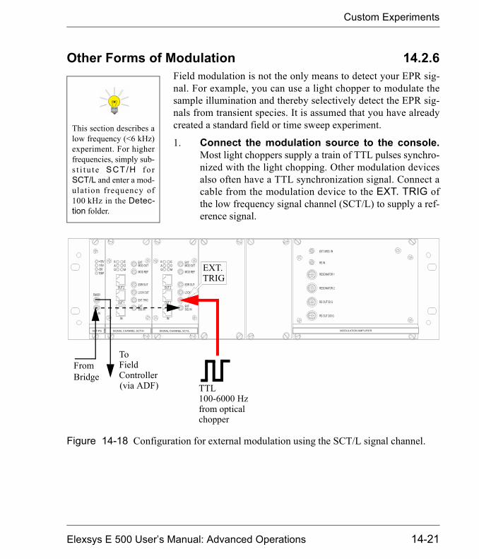
Custom Experiments
Other Forms of Modulation 14.2.6Field modulation is not the only means to detect your EPR sig-nal. For example, you can use a light chopper to modulate thesample illumination and thereby selectively detect the EPR sig-nals from transient species. It is assumed that you have alreadycreated a standard field or time sweep experiment.
1. Connect the modulation source to the console.Most light choppers supply a train of TTL pulses synchro-nized with the light chopping. Other modulation devicesalso often have a TTL synchronization signal. Connect acable from the modulation device to the EXT. TRIG ofthe low frequency signal channel (SCT/L) to supply a ref-erence signal.
This section describes alow frequency (<6 kHz)experiment. For higherfrequencies, simply sub-s t i t u t e SCT/H f o rSCT/L and enter a mod-ulation frequency of100 kHz in the Detec-tion folder.
Figure 14-18 Configuration for external modulation using the SCT/L signal channel.
FromBridge
ToField
(via ADF)Controller
TTL100-6000 Hzfrom opticalchopper
EXT.TRIG
Elexsys E 500 User�s Manual: Advanced Operations 14-21

Custom Experiments
2. Enable external modulation. Open the Parameterdialog box and click the Signal I/O tab of the SignalChannel folder. (See Figure 14-19.) Click ExternalLock In to activate it (green). You must change the modu-lation phase by using an external phase shifter. The Ext.Lock In Delay does not change the phase in this case.
Figure 14-19 Parameter setup for the optical modulation.
ExternalLock In
14-22
Custom Experiments
3. Set more parameters. Since this is a low frequencymodulation experiment, we recommend deactivating (notgreen) the High Pass Filter button and selecting theLock In Integrator option to reduce the noise. (SeeFigure 14-19.) Make sure you enter a modulation fre-quency value below 6 kHz in the Modulation Frequencyof the Detection folder. This forces the acquisition soft-ware to use the low frequency signal channel.
4. Acquire a spectrum. Click the Run button.
Elexsys E 500 User�s Manual: Advanced Operations 14-23
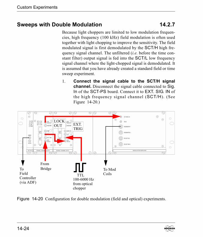
Custom Experiments
Sweeps with Double Modulation 14.2.7Because light choppers are limited to low modulation frequen-cies, high frequency (100 kHz) field modulation is often usedtogether with light chopping to improve the sensitivity. The fieldmodulated signal is first demodulated by the SCT/H high fre-quency signal channel. The unfiltered (i.e. before the time con-stant filter) output signal is fed into the SCT/L low frequencysignal channel where the light-chopped signal is demodulated. Itis assumed that you have already created a standard field or timesweep experiment.
1. Connect the signal cable to the SCT/H signalchannel. Disconnect the signal cable connected to Sig.In of the SCT-PS board. Connect it to EXT. SIG. IN ofthe high frequency signal channel (SCT/H). (SeeFigure 14-20.)
Figure 14-20 Configuration for double modulation (field and optical) experiments.
FromBridge To Mod
CoilsTTL100-6000 Hzfrom opticalchopper
ToField
(via ADF)Controller
LOCKOUT EXT.
TRIG
14-24
Custom Experiments
2. Connect LOCK OUT to EXT. SIG. IN. Connect LOCKOUT of the high frequency signal channel (SCT/H) toEXT. SIG. IN of the low frequency signal channel(SCT/L) with an external cable. (See Figure 14-20.)
3. Connect EXT. MOD OUT to EXT MOD. IN. ConnectEXT. MOD OUT of the high frequency signal channel(SCT/H) to EXT. MOD. IN of the Modulation Amplifierwith an external cable. (See Figure 14-20.)
4. Provide a TTL reference to EXT. TRIG. Connect thecable carrying the pulses from the light chopper or otherlow frequency modulation supplier to EXT. TRIG of thel o w f r e q u e n c y s i g n a l c h a n n e l (SCT/L ) . ( S e eFigure 14-20.)
Elexsys E 500 User�s Manual: Advanced Operations 14-25

Custom Experiments
5. Enable Double Modulation. Open the Parameterdialog box and click the Signal Channel folder. Click theDouble Modulation tab. Activate (green) Double Modu-lation. Select Second in the Detecting SCT drop-downlist. Select First in the Field Modulation SCT drop-downlist. You may need to reduce Receiver Gain values forboth signal channels. Note that the Time Constant in thisfolder controls the time constant for the low frequency(Detecting SCT) signal channel. (See Figure 14-21.)
Figure 14-21 Enabling Double Modulation.
14-26

Custom Experiments
6. Set up the Signal I/O. Click the Signal I/O tab. SelectExternal for Signal Input, Modulation Input, and Mod-ulation Output. (See Figure 14-22.)
Figure 14-22 Enabling external inputs and outputs in Signal I/O.
Elexsys E 500 User�s Manual: Advanced Operations 14-27

Custom Experiments
7. Configure Double Mod. Signal I/O. Click the Dou-ble Mod. Signal I/O tab. Select External for SignalInput. You may need to activate the High Pass Filter andthe Lock In Integrator to reduce the noise. Click Exter-nal Lock In to activate it (green). (See Figure 14-23.)
Figure 14-23 Configuring Double Mod. Signal I/O.
ChangePhase
14-28
Custom Experiments
8. Adjust the low frequency modulation phase. Youcan adjust the phase of the low frequency modulation.Convert the phase value in degrees you want to adjust todelay time (in �s) based on the following formula:
[14-1]
Enter the value in the Ext. Lock In Delay box. (SeeFigure 14-23.)
9. Acquire a spectrum. Click the Run button.
Delay(�s) Phase 1000�
360 Modulation Frequency(kHz)�----------------------------------------------------------------------------------=
Elexsys E 500 User�s Manual: Advanced Operations 14-29
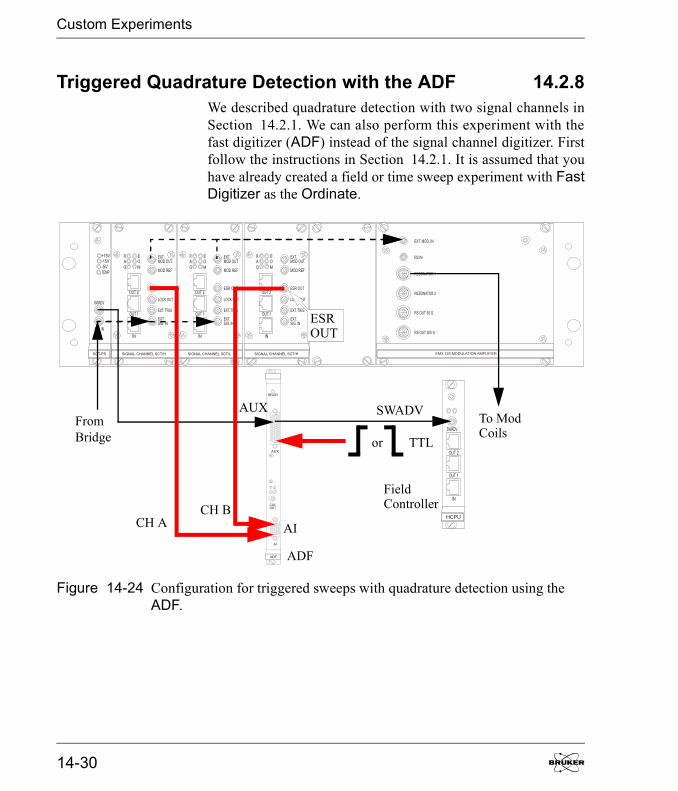
Custom Experiments
Triggered Quadrature Detection with the ADF 14.2.8We described quadrature detection with two signal channels inSection 14.2.1. We can also perform this experiment with thefast digitizer (ADF) instead of the signal channel digitizer. Firstfollow the instructions in Section 14.2.1. It is assumed that youhave already created a field or time sweep experiment with FastDigitizer as the Ordinate.
Figure 14-24 Configuration for triggered sweeps with quadrature detection using theADF.
Field
ADF
To ModFromBridge
CH A
TTLor
Controller
Coils
CH BAI
AUX
ESROUT
SWADV
14-30

Custom Experiments
1. Cable connections. Connect the two ESR OUT sig-nals from the two identical signal channels to Channel Aand Channel B of the AI connectors on the ADF board.(See Section 13.7.2 for the pin lay out of the AI connectorof the ADF board.) You can use the cable labeled ADFENDOR on the AI connector as Channel B. You also needto send a TTL trigger pulse to the cable labeled Ext. Trig-ger from the AUX connector on the ADF board. (SeeFigure 14-24.)
2. Set up the parameters. Open the Parameter dialogbox and click the Fast Digitizer tab. Select ExternalSweep or External Point in the Trigger Modedrop-down list. Select the appropriate Trigger Slope foryour trigger pulse. Select A&B in the Input Mode. (SeeFigure 14-25.) The signal from the Channel A is stored asthe real part of the spectrum while the signal from Chan-nel B is stored as the imaginary part of the spectrum. Youcan view each of them by clicking the Re/Im button in theTool bar.
3. Acquire a spectrum. Click the Run button.
Figure 14-25 Setting up the ADF for quadrature detection.
Elexsys E 500 User�s Manual: Advanced Operations 14-31
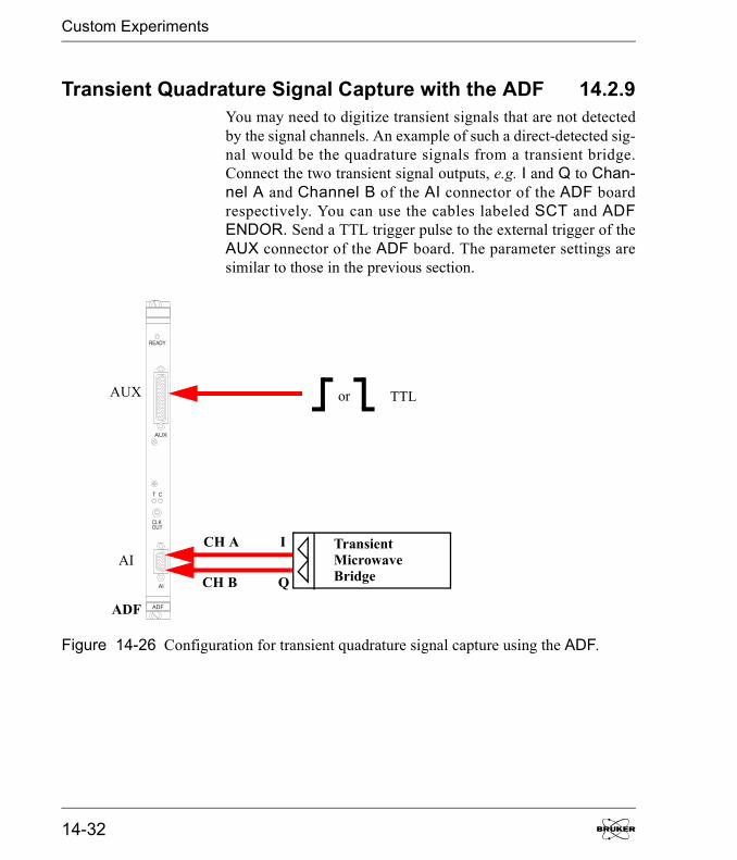
Custom Experiments
Transient Quadrature Signal Capture with the ADF 14.2.9You may need to digitize transient signals that are not detectedby the signal channels. An example of such a direct-detected sig-nal would be the quadrature signals from a transient bridge.Connect the two transient signal outputs, e.g. I and Q to Chan-nel A and Channel B of the AI connector of the ADF boardrespectively. You can use the cables labeled SCT and ADFENDOR. Send a TTL trigger pulse to the external trigger of theAUX connector of the ADF board. The parameter settings aresimilar to those in the previous section.
Figure 14-26 Configuration for transient quadrature signal capture using the ADF.
TransientMicrowaveBridge
TTLor
CH A
CH B
I
Q
ADF
AUX
AI
14-32

Custom Experiments
Externally Controlled Field Sweep with the ADF 14.2.10If you have your own field sweep device you can direct the fieldsweep pulses to the external trigger input of the AUX connectoron the ADF board and the SWADV (sweep address advance) onthe field controller board.
You must enable external point triggering and define the slope inthe digitizer parameter menu. Table 14-1 shows the sweep
Figure 14-27 Externally controlled field sweeps using the ADF.
FieldADF
To ModFromBridge
CH A
TTL
Controller
1 - 10 �s
Coils
SWADVAUX
AI
Elexsys E 500 User�s Manual: Advanced Operations 14-33
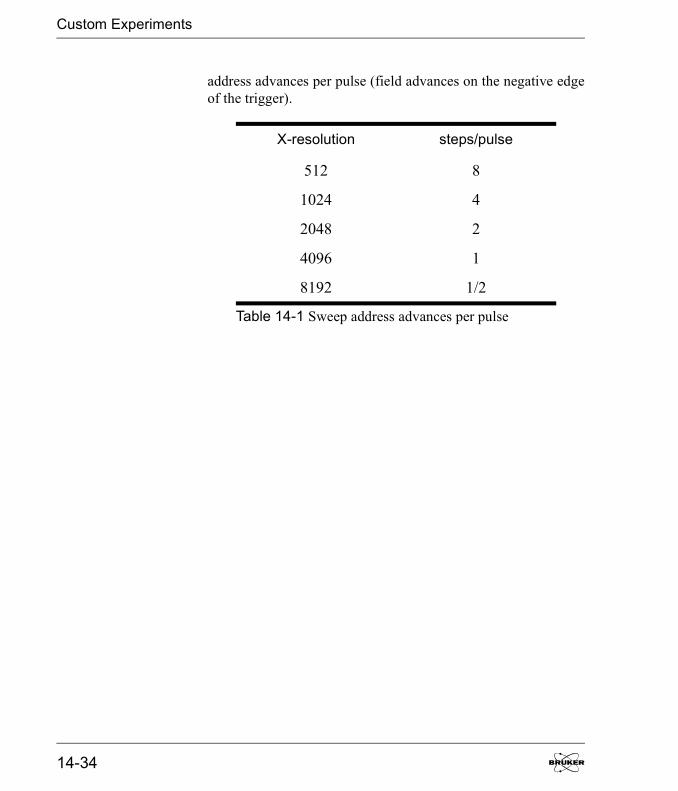
Custom Experiments
address advances per pulse (field advances on the negative edgeof the trigger).
X-resolution steps/pulse
512 8
1024 4
2048 2
4096 1
8192 1/2
Table 14-1 Sweep address advances per pulse
14-34
Xepr Under SGI IRIX 15Bruker delivers either SGI O2 or Linux workstations for the userinterface of the Elexsys series EPR spectrometers. This chapterdescribes various system administration issues related to theXepr program for the SGI O2 workstation. The names or termsdescribed in this chapter may differ slightly for the Linux sys-tem, but the principles are the same. Refer to Chapter 16 fordetails if you have a Linux workstationMost of the commands and operations in this chapter requireroot or super user privileges. In addition, the commands alsorequire at least some basic knowledge of the UNIX operatingsystem. This chapter assumes that you already are familiar withgeneral administration of the UNIX operating system. Be cau-tious when making changes to the workstation configuration:some mistakes can lead to an unusable workstation. Consultyour local Bruker EPR service representative if you are unsureof the changes you are making.
General Information 15.1The SGI O2 workstation comes with two Ethernet cards and theIRIX 6.5 UNIX operating system. IRIX 6.3 is no longer sup-ported, although Xepr still functions under 6.3.
If you wish to check the hardware inventory (system ID, RAM,CPU, IP address, etc.) for your workstation, use the shell com-mand hinv. If you prefer to use a GUI (Graphical User Interface)tool, select Toolchest > System > System Manager > AboutThis System to check the hardware inventory.The system as delivered by Bruker has two visible accounts: theroot account with the password xepr@sgi and the xuseraccount with the password user@xepr. For your security,change the root password immediately after the system has beeninstalled.
Most of the Xepr files reside in the /usr/xepr folder.
Elexsys E 500 User�s Manual: Advanced Operations
Network Settings
Network Settings 15.2
ec0 and ec1 15.2.1The two Ethernet cards in the workstation are labeled ec0 andec1. ec0 is used for connecting to the outside world and is con-figured as the primary interface. ec1 is devoted to communica-tions between the workstation and the acquisition server (OS9)of the spectrometer and is configured as the secondary interface.When the workstation is delivered, the hostname and IP addressof ec0 are set to default values. You need to ask your local net-work administrator to assign a hostname and an IP address foryour workstation. Change the hostname and IP address of ec0only. Never change the hostname and IP address of ec1.
NFS (Network File System) 15.2.2Xepr uses NFS to transfer files between the UNIX workstationand the acquisition server. Never turn off or deactivate NFS.
UNS (Unified Name Service) 15.2.3UNS allows you to use easily remembered host names instead ofeasily forgotten IP addresses. The most common services arefiles, DNS (Domain Name Service), and NIS (Network Infor-mation Service).
Files This is the most controllable way to provide network informa-tion. Entries in the /etc/hosts file connect an IP address with acorresponding host name. You can simply edit this file to definethe names and IP addresses of the computers in your local net-work as well as on the Internet. The hosts file must contain thelocal host.
Never change ec1 toprimary.
15-2
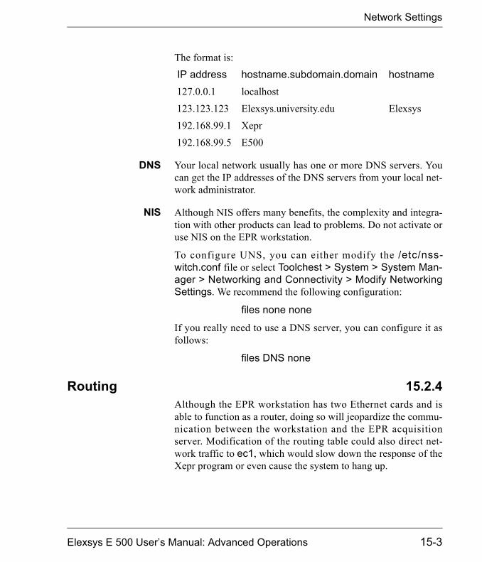
Network Settings
The format is:
IP address hostname.subdomain.domain hostname127.0.0.1 localhost
123.123.123 Elexsys.university.edu Elexsys
192.168.99.1 Xepr
192.168.99.5 E500
DNS Your local network usually has one or more DNS servers. Youcan get the IP addresses of the DNS servers from your local net-work administrator.
NIS Although NIS offers many benefits, the complexity and integra-tion with other products can lead to problems. Do not activate oruse NIS on the EPR workstation.
To configure UNS, you can either modify the /etc/nss-witch.conf file or select Toolchest > System > System Man-ager > Networking and Connectivity > Modify NetworkingSettings. We recommend the following configuration:
files none none
If you really need to use a DNS server, you can configure it asfollows:
files DNS none
Routing 15.2.4Although the EPR workstation has two Ethernet cards and isable to function as a router, doing so will jeopardize the commu-nication between the workstation and the EPR acquisitionserver. Modification of the routing table could also direct net-work traffic to ec1, which would slow down the response of theXepr program or even cause the system to hang up.
Elexsys E 500 User�s Manual: Advanced Operations 15-3

UNIX Workstation Configuration
UNIX Workstation Configuration 15.3
Flags 15.3.1Flags are used to activate and deactivate various services that theworkstation can offer. Here is the standard configuration for anSGI IRIX workstation as delivered by Bruker. You can check theconfiguration by entering chkconfig in a UNIX shell. The net-work and nfs services must be on to allow the workstation tocommunicate with the acquisition server properly. Although youcan turn on more services than the basic configuration, keep inmind that the more services you turn on, especially networkrelated services, the slower the workstation responds.
Flag Status Flag Status
appletalk off privileges on
array off proclaim_relayagent off
autoconfig_ipaddress off proclaim_server off
autofs on proxymngr off
automount off rarpd off
bsdlpr on routed off
desktop on rsvpd off
fontserver off rtmond on
gated off rwhod off
ipaliases on sar off
isdnd off savecore on
lockd on sdpd on
Table 15-1 Standard configuration for workstation services.
15-4
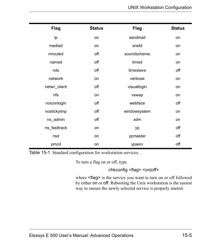
UNIX Workstation Configuration
To turn a flag on or off, type
chkconfig <flag> <on|off>
where <flag> is the service you want to turn on or off followedby either on or off. Rebooting the Unix workstation is the easiestway to ensure the newly selected service is properly started.
lp on sendmail on
mediad on snetd on
mrouted off soundscheme on
named off timed on
nds off timeslave off
network on verbose on
netwr_client off visuallogin on
nfs on vswap on
noiconlogin off webface off
nostickytmp off windowsystem on
ns_admin off xdm on
ns_fasttrack on yp off
nsd on ypmaster off
pmcd on ypserv off
Flag Status Flag Status
Table 15-1 Standard configuration for workstation services.
Elexsys E 500 User�s Manual: Advanced Operations 15-5
UNIX Workstation Configuration
Swap Space 15.3.2The best way to determine the optimal swap space size is to tryseveral sizes. We recommend setting the swap space size to fourtimes the RAM size. When the swap space is not large enoughthere will be an error message in the /var/adm/SYSLOG file orin the console window. If you routinely process several large 2Ddatasets in Xepr you may need to increase your swap space.There are two types of swap space: the hard disk swap space andthe swap file. The swap file is slower than the hard disk swapspace. To increase the hard disk swap space you need to reparti-tion the hard drive which wipes out the contents of the hard disk.The fastest swap space configuration is to have swap spaces onboth the system hard disk and the secondary hard disk.
Security 15.3.3Functionality, accessibility, and convenience may compromisethe system security. Balancing these considerations is not a sim-ple job. Refer to the SGI workstation administrative manual forsecurity settings that best suit you. We suggest the following.
Lock accounts There are a few accounts utilized by Xepr such as the guest andlp accounts. Never delete the guest and lp accounts. Instead,lock these accounts and other �open to the public� accounts suchas demos, EZsetup, OutOfBox, etc.
Root and SuperUser
Avoid logging in as root or super user. Only do so when youmust perform system administration tasks. Xepr should be runout of your personal user account or xuser account.
Transitive Trust The UNIX operating system allows users to set host-to-hostequivalency (in the /etc/hosts.equiv file), user-to-user equiva-lency (in the ~/.rhosts file), and ftp user equivalency (in the~/ .ne t rc f i l e ) . I n h i g h s e c u r i ty e n v i r o n m e n t s , t h e/etc/host.equiv file is blank and the ~/.rhosts and ~/.netrc filesin the user accounts are usually removed.
15-6
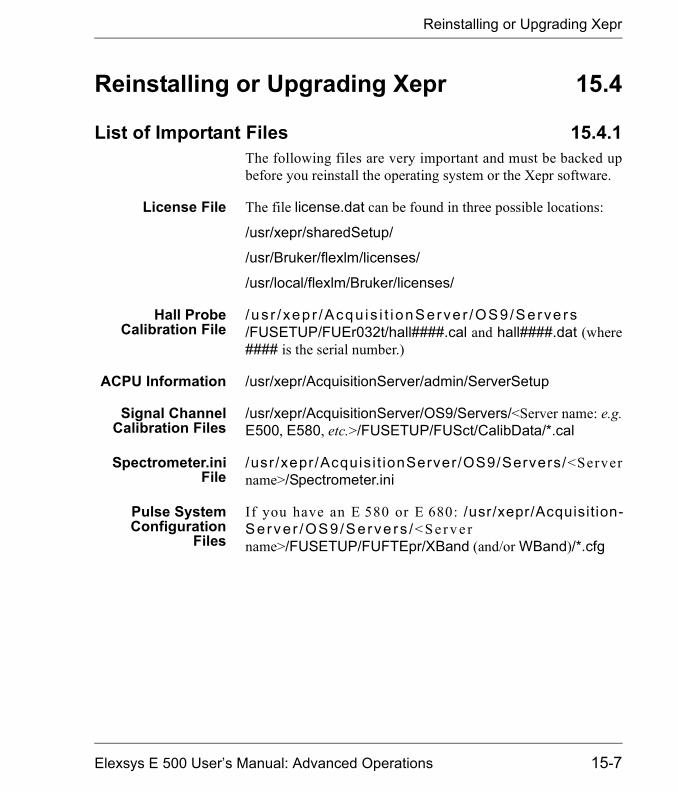
Reinstalling or Upgrading Xepr
Reinstalling or Upgrading Xepr 15.4
List of Important Files 15.4.1The following files are very important and must be backed upbefore you reinstall the operating system or the Xepr software.
License File The file license.dat can be found in three possible locations:
/usr/xepr/sharedSetup/
/usr/Bruker/flexlm/licenses/
/usr/local/flexlm/Bruker/licenses/
Hall ProbeCalibration File
/ us r / xep r /Acqu is i t i onServe r /OS9/Serve rs/FUSETUP/FUEr032t/hall####.cal and hall####.dat (where#### is the serial number.)
ACPU Information /usr/xepr/AcquisitionServer/admin/ServerSetup
Signal ChannelCalibration Files
/usr/xepr/AcquisitionServer/OS9/Servers/<Server name: e.g.E500, E580, etc.>/FUSETUP/FUSct/CalibData/*.cal
Spectrometer.iniFile
/usr/xepr/Acquis i t ionServer/OS9/Servers/<Servername>/Spectrometer.ini
Pulse SystemConfiguration
Files
If you have an E 580 or E 680: /usr/xepr/Acquisition-Server /OS9/Serve rs /< S e r v e rname>/FUSETUP/FUFTEpr/XBand (and/or WBand)/*.cfg
Elexsys E 500 User�s Manual: Advanced Operations 15-7

Reinstalling or Upgrading Xepr
Performing an Installation or Upgrade 15.4.21. Check the current version of Xepr. Use the shell
command Xepr -i to determine the version of the cur-rently installed Xepr software.
2. Follow the instructions in the release note. Loginas root to install Xepr. Read the release note on the XeprCD first. Follow the instructions for installing Xepr. Usethe default installation settings to avoid any unforeseenproblems. Sometimes you may need to delete the/usr/xepr folder before you install the Xepr software.
3. Restore the backed up files. Put the files you backedup in Section 15.4.1 into the folders from which theycame.
4. Install the acquisition server. Each time you reinstallXepr or upgrade the acquisition package you must rein-stall the acquisition server. The acquisition server installa-t i o n s c r i p t i s l o c a t e d i n t h e f o l d e r/usr/xepr/AcquisitionServer/admin/. Make sure youhave the correct ServerSetup file. Change to the abovedirectory and type ./installServer to install the acquisi-tion server.
5. Reboot the UNIX workstation. If you do not, theupgrade or installation will not work properly.
15-8

Initial Setup of Xepr
Initial Setup of Xepr 15.5Normally users have their own account. If you do not have anaccount yet ask the system administrator to create one for you. Ifyou are responsible for the system and want to create a user�saccount, refer to the SGI workstation manual or help to find outhow to create a user�s account. A user�s account has a user�saccount name, user ID, and a password to log into the account.After you log into your account, you can configure your desktop,windows, UNIX shell type, and other features. You can alsochange your password. Refer to the Toolchest help menu forconfiguration of your account. When you run Xepr for the firsttime in your own account, Xepr will automatically configureyour home directory to setup Xepr.
Setting Up Xepr for Your Account 15.5.11. Find the Xepr icon. Click the Toolchest > Find > Icon
Catalog > Applications. A window of application pro-gram icons will appear. (See Figure 15-1.)
Figure 15-1 Opening the Applications icon window.
Applications
Elexsys E 500 User�s Manual: Advanced Operations 15-9

Initial Setup of Xepr
2. Setup a desktop icon for Xepr. In the Applicationsi con window you can f ind the Xepr icon . (SeeFigure 15-2.) Drag the icon onto to the desktop. Now youcan launch the Xepr software from the Desktop.
3. Start Xepr program for the first time. Double clickthe Xepr icon. The Xepr program will automatically con-figure your account to run Xepr and launch the Xepr pro-gram.
Figure 15-2 The Xepr icon.
XeprIcon
15-10
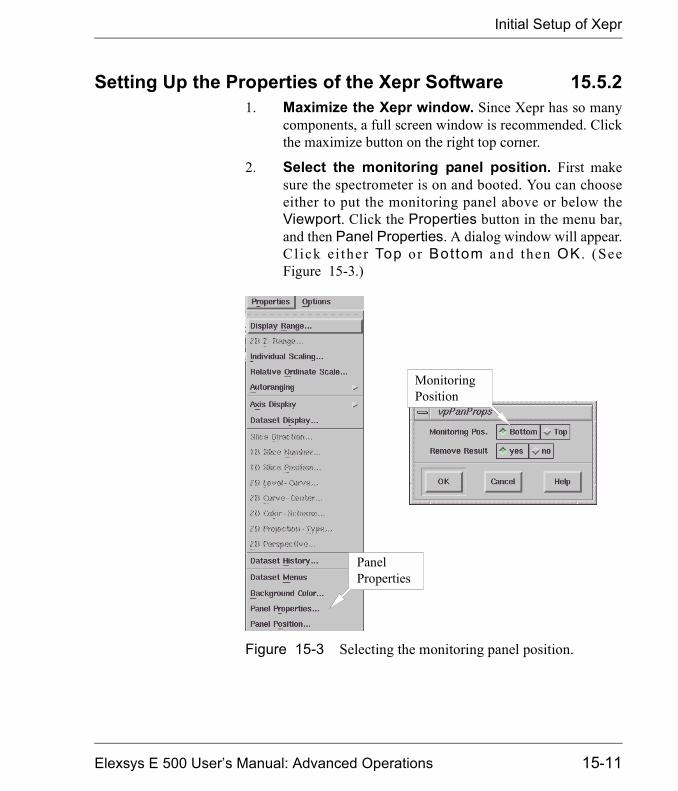
Initial Setup of Xepr
Setting Up the Properties of the Xepr Software 15.5.21. Maximize the Xepr window. Since Xepr has so many
components, a full screen window is recommended. Clickthe maximize button on the right top corner.
2. Select the monitoring panel position. First makesure the spectrometer is on and booted. You can chooseeither to put the monitoring panel above or below theViewport. Click the Properties button in the menu bar,and then Panel Properties. A dialog window will appear.Cl ick ei ther Top or Bottom and then OK . (SeeFigure 15-3.)
Figure 15-3 Selecting the monitoring panel position.
PanelProperties
MonitoringPosition
Elexsys E 500 User�s Manual: Advanced Operations 15-11
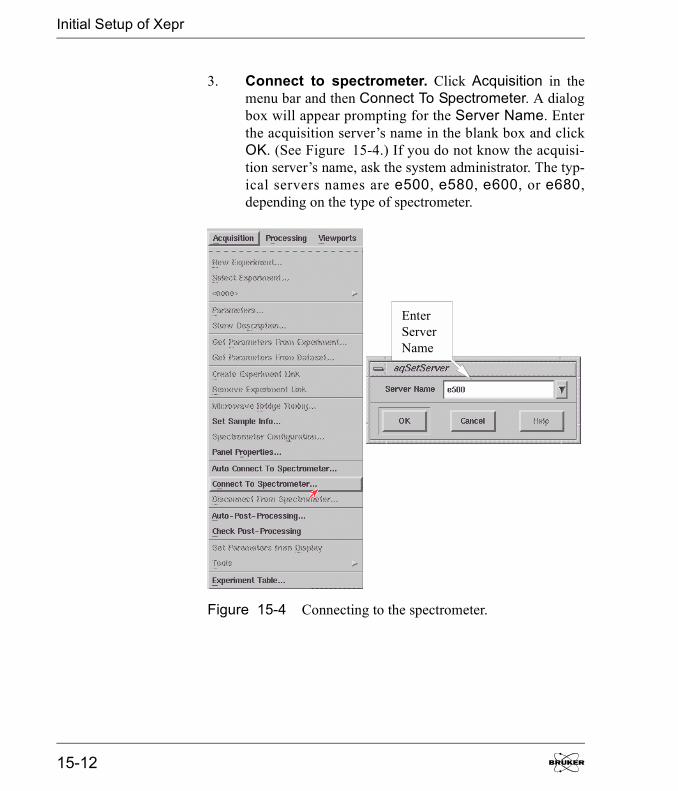
Initial Setup of Xepr
3. Connect to spectrometer. Click Acquisition in themenu bar and then Connect To Spectrometer. A dialogbox will appear prompting for the Server Name. Enterthe acquisition server�s name in the blank box and clickOK. (See Figure 15-4.) If you do not know the acquisi-tion server�s name, ask the system administrator. The typ-ical servers names are e500, e580, e600, or e680,depending on the type of spectrometer.
Figure 15-4 Connecting to the spectrometer.
EnterServerName
15-12
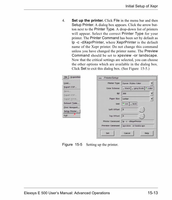
Initial Setup of Xepr
4. Set up the printer. Click File in the menu bar and thenSetup Printer. A dialog box appears. Click the arrow but-ton next to the Printer Type. A drop-down list of printerswill appear. Select the correct Printer Type for yourprinter. The Printer Command has been set by default aslp -c -dXeprPrinter, where XeprPrinter is the defaultname of the Xepr printer. Do not change this commandunless you have changed the printer name. The PreviewCommand should be set to xpsview -or landscape.Now that the critical settings are selected, you can choosethe other options which are available in the dialog box.Click Set to exit this dialog box. (See Figure 15-5.)
Figure 15-5 Setting up the printer.
Elexsys E 500 User�s Manual: Advanced Operations 15-13
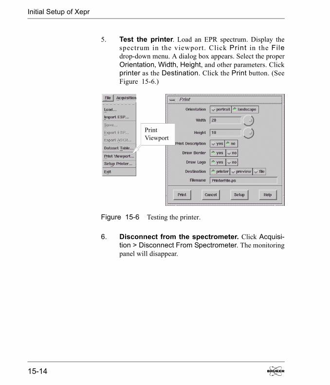
Initial Setup of Xepr
5. Test the printer. Load an EPR spectrum. Display thespectrum in the viewport. Click Print in the Filedrop-down menu. A dialog box appears. Select the properOrientation, Width, Height, and other parameters. Clickprinter as the Destination. Click the Print button. (SeeFigure 15-6.)
6. Disconnect from the spectrometer. Click Acquisi-tion > Disconnect From Spectrometer. The monitoringpanel will disappear.
Figure 15-6 Testing the printer.
PrintViewport
15-14

Initial Setup of Xepr
7. Exit Xepr. Click File and then Exit in the menu bar. Adialog box appears asking you if you want to save thechanges. Click Yes and then OK to exit Xepr program.(See Figure 15-7.) Next time you launch the Xepr soft-ware, you will find the Server Name appearing in theConnect to Spectrometer dialog box. The printer willbe ready to print.
8. Logout from your account. It is always a good idea tologout from your account when you finish your work.
Figure 15-7 Saving the changes and exiting.
If you do not save yourchanges, none of yourch a n g es wi l l b eremembered the nexttime you start Xepr.
ExitXepr
SaveChanges
Elexsys E 500 User�s Manual: Advanced Operations 15-15

How to Start and Stop Xepr
How to Start and Stop Xepr 15.6This section describes different ways to start the Xepr program.It also describes how to abort the Xepr program when things gowrong and the system hangs up.
Starting Xepr from a UNIX shell 15.6.1There are two basic ways to launch the Xepr program. One is todouble click the Xepr icon. You can find the Xepr icon on theDesktop or in the Icon Catalog: Applications window. Thealternative way to start Xepr is to launch Xepr from a UNIXshell.
1. Open a UNIX shell. Click Desktop > Toolchest >Open UNIX Shell. A shell window will open.
Figure 15-8 Opening a UNIX shell.
Open UNIXShell
15-16
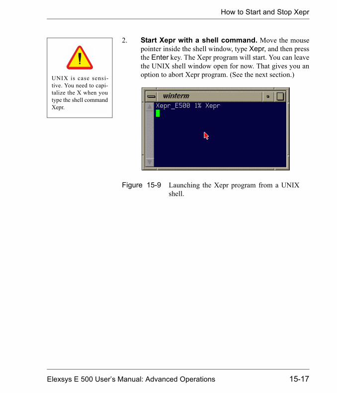
How to Start and Stop Xepr
2. Start Xepr with a shell command. Move the mousepointer inside the shell window, type Xepr, and then pressthe Enter key. The Xepr program will start. You can leavethe UNIX shell window open for now. That gives you anoption to abort Xepr program. (See the next section.)
Figure 15-9 Launching the Xepr program from a UNIXshell.
UNIX is case sensi-tive. You need to capi-talize the X when youtype the shell commandXepr.
Elexsys E 500 User�s Manual: Advanced Operations 15-17

Aborting Xepr
Aborting Xepr 15.7Normally you need to exit Xepr by clicking File in the menu bar,and then clicking Exit to terminate the Xepr program. However,when something goes wrong or the system hangs up, you maynot be able to exit Xepr by normal methods. Keep in mind,sometimes Xepr needs more time to execute certain functionsespecially the communications between the system and slowdevices. It may not respond to your command instantly. GiveXepr some extra time. Avoid continuously clicking the mousebutton: it only make the system even busier. When memory isrunning too low or there is too much network traffic, Xepr mighthang up. Keep clearing up the Result Dataset. Avoid loadingtoo many large data files into Xepr. Reduce network activitiesparticularly when you connect to the spectrometer. These thingswill help you reduce the possibility of hanging up. If you fail toclose Xepr in the normal way, we suggest the following. First trythe normal procedure to exit Xepr. If that fails, try aborting bythe methods described in this section. After you abort Xepr, turnoff the console and turn on the console again before you recon-nect to spectrometer.
Logout from the Current Account. 15.7.1This is the easiest way to abort Xepr. Simply follow the logoutprocedure described in Appendix A of the Elexsys E 500 User�sManual: Basic Operations and the Xepr program will be termi-nated.
The Ctrl-C command 15.7.2If you start the Xepr program from a UNIX shell, you can alsouse the Ctrl-C command to abort Xepr program. This is a grace-ful way to terminate the Xepr. Minimize (iconize) the Xepr win-dow. Move the mouse pointer inside the UNIX shell windowfrom which you launched Xepr program. Press the <Ctrl> key
15-18
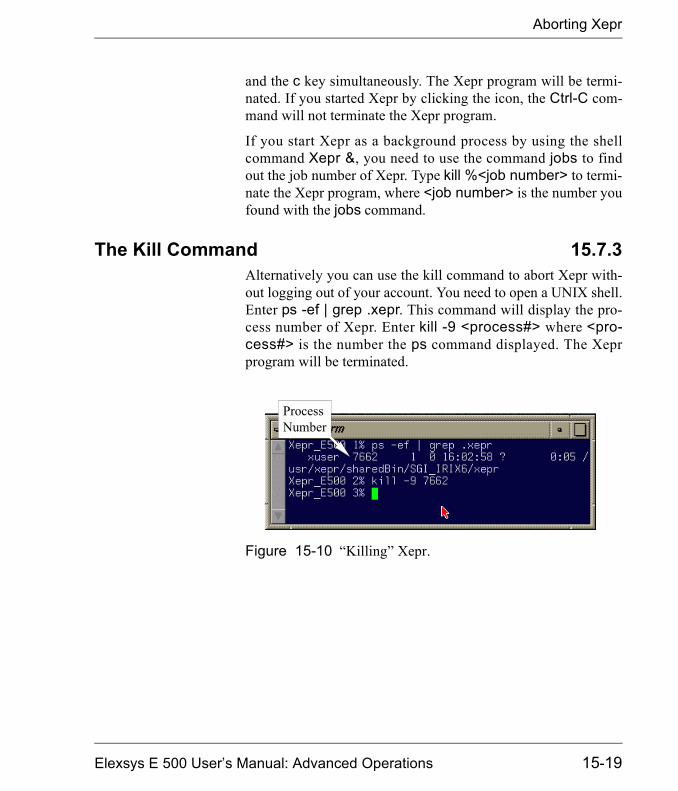
Aborting Xepr
and the c key simultaneously. The Xepr program will be termi-nated. If you started Xepr by clicking the icon, the Ctrl-C com-mand will not terminate the Xepr program.
If you start Xepr as a background process by using the shellcommand Xepr &, you need to use the command jobs to findout the job number of Xepr. Type kill %<job number> to termi-nate the Xepr program, where <job number> is the number youfound with the jobs command.
The Kill Command 15.7.3Alternatively you can use the kill command to abort Xepr with-out logging out of your account. You need to open a UNIX shell.Enter ps -ef | grep .xepr. This command will display the pro-cess number of Xepr. Enter kill -9 <process#> where <pro-cess#> is the number the ps command displayed. The Xeprprogram will be terminated.
Figure 15-10 �Killing� Xepr.
ProcessNumber
Elexsys E 500 User�s Manual: Advanced Operations 15-19
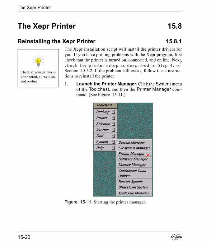
The Xepr Printer
The Xepr Printer 15.8
Reinstalling the Xepr Printer 15.8.1The Xepr installation script will install the printer drivers foryou. If you have printing problems with the Xepr program, firstcheck that the printer is turned on, connected, and on line. Next,c h ec k th e p r in te r s e tu p as d es c r ib e d in St ep 4 . o fSection 15.5.2. If the problem still exists, follow these instruc-tions to reinstall the printer.
1. Launch the Printer Manager. Click the System menuof the Toolchest, and then the Printer Manager com-mand. (See Figure 15-11.)
Figure 15-11 Starting the printer manager.
Check if your printer isconnected, turned on,and on-line.
15-20
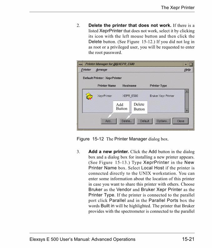
The Xepr Printer
2. Delete the printer that does not work. If there is alisted XeprPrinter that does not work, select it by clickingits icon with the left mouse button and then click theDelete button. (See Figure 15-12.) If you did not log inas root or a privileged user, you will be requested to enterthe root password.
3. Add a new printer. Click the Add button in the dialogbox and a dialog box for installing a new printer appears.(See Figure 15-13.) Type XeprPrinter in the NewPrinter Name box. Select Local Host if the printer isconnected directly to the UNIX workstation. You canenter some information about the location of this printerin case you want to share this printer with others. ChooseBruker as the Vendor and Bruker Xepr Printer as thePrinter Type. If the printer is connected to the parallelport click Parallel and in the Parallel Ports box thewords Built in will be highlighted. The printer that Brukerprovides with the spectrometer is connected to the parallel
Figure 15-12 The Printer Manager dialog box.
AddButton
DeleteButton
Elexsys E 500 User�s Manual: Advanced Operations 15-21
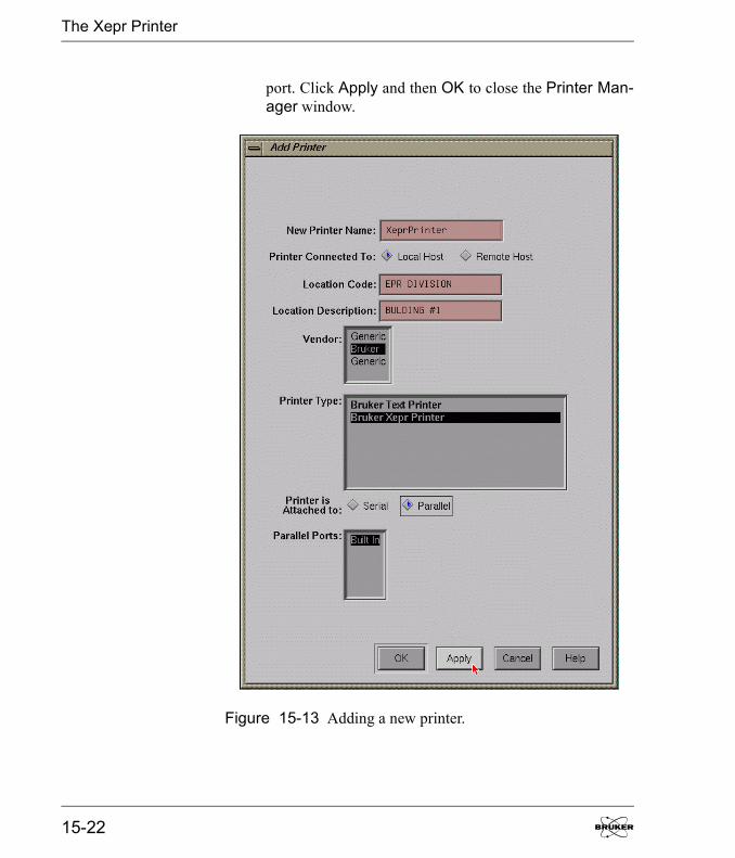
The Xepr Printer
port. Click Apply and then OK to close the Printer Man-ager window.
Figure 15-13 Adding a new printer.
15-22
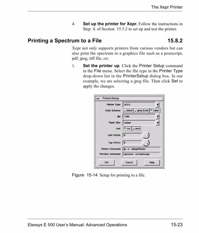
The Xepr Printer
4. Set up the printer for Xepr. Follow the instructions inStep 4. of Section 15.5.2 to set up and test the printer.
Printing a Spectrum to a File 15.8.2Xepr not only supports printers from various vendors but canalso print the spectrum to a graphics file such as a postscript,pdf, jpeg, tiff file, etc.
1. Set the printer up. Click the Printer Setup commandin the File menu. Select the file type in the Printer Typedrop-down list in the PrinterSetup dialog box. In ourexample, we are selecting a jpeg file. Then click Set toapply the changes.
Figure 15-14 Setup for printing to a file.
Elexsys E 500 User�s Manual: Advanced Operations 15-23

The Xepr Printer
2. Print to a file. Click Print Viewport in the File menu.Click File in the Destination section. Enter a file nameand select the desired options for the data set plot. (SeeFigure 15-15.) Click Print and the file will be saved intoyour home directory.
Figure 15-15 Printing to a file.
15-24
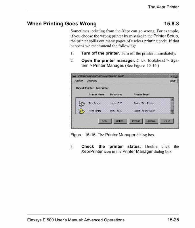
The Xepr Printer
When Printing Goes Wrong 15.8.3Sometimes, printing from the Xepr can go wrong. For example,if you choose the wrong printer by mistake in the Printer Setup,the printer spills out many pages of useless printing code. If thathappens we recommend the following:
1. Turn off the printer. Turn off the printer immediately.
2. Open the printer manager. Click Toolchest > Sys-tem > Printer Manager. (See Figure 15-16.)
3. Check the printer status. Double click theXeprPrinter icon in the Printer Manager dialog box.
Figure 15-16 The Printer Manager dialog box.
Elexsys E 500 User�s Manual: Advanced Operations 15-25
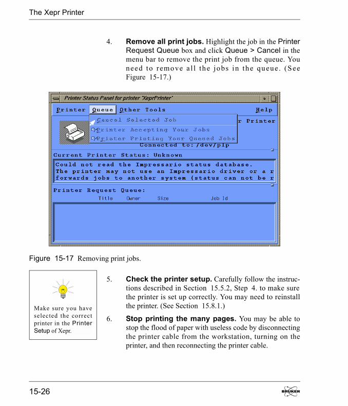
The Xepr Printer
4. Remove all print jobs. Highlight the job in the PrinterRequest Queue box and click Queue > Cancel in themenu bar to remove the print job from the queue. Youneed to remove a l l the jobs in the queue. (SeeFigure 15-17.)
5. Check the printer setup. Carefully follow the instruc-tions described in Section 15.5.2, Step 4. to make surethe printer is set up correctly. You may need to reinstallthe printer. (See Section 15.8.1.)
6. Stop printing the many pages. You may be able tostop the flood of paper with useless code by disconnectingthe printer cable from the workstation, turning on theprinter, and then reconnecting the printer cable.
Figure 15-17 Removing print jobs.
Make sure you haveselected the correctprinter in the PrinterSetup of Xepr.
15-26
Networking & Remote Operation
Networking & Remote Operation 15.9The Elexsys E 500 series EPR spectrometer is designed to oper-ate in a networked environment. The workstation is equippedwith two Ethernet cards. The primary network adapter (ec0)connects the workstation to the outside network. The secondarynetwork adapter (ec1) is solely dedicated to communicationbetween the workstation and the acquisition server of the EPRspectrometer. This client/server architecture resolves the conflictbetween multi-user/multi-tasking on the one hand and real-timefunctionality on the other hand. Therefore, multiple users fromdifferent locations are able to access Xepr remotely. However,excessive communication between the workstation and the out-side world not only slows down the Xepr program but alsoopens the door for unauthorized access. Although the worksta-tion is capable of functioning as a general network server it ishighly recommended to use the Elexsys EPR workstation foracquiring EPR spectra only. The administrator of the worksta-tion needs to carefully balance the security of the Elexsys work-station and public network access. This section discusses datatransfer through the network and remote login to the work sta-tion.
Remote Access to Xepr 15.9.1You can log onto the workstation remotely, allowing multipleusers access to the Xepr software at the same time. Each userremotely logs into the workstation and launches the Xepr soft-ware. In the following section we refer to the workstationdirectly connected to the Elexsys spectrometer as the EPR serverand the other computers connected to the EPR server throughnetwork as clients.
Elexsys E 500 User�s Manual: Advanced Operations 15-27
Networking & Remote Operation
Remote Logon to the EPR Server 15.9.2The client and the EPR server should be assigned appropriate IPaddresses and connected to the same network. The primary net-work connection (ec0) of the EPR server should be used to con-nect to the network. In order to display the Xepr applicationwindow on the client�s monitor, you must either activate remotedisplay on the client computer (if the client has a UNIX operat-ing system) or use special software, such as PC-Xware (if theoperating system is Windows). You also need a valid useraccount on the EPR server.
From a UNIXSystem
On the client computer, remote display is enabled by executingthe shell command,
xhost + <EPR server’s IP address>
In the shell window, enter
telnet <EPR server IP address>
Enter the user�s name and password when you are prompted.After logging into the EPR server, type Xepr to launch the Xeprprogram.
From a WindowsSystem
Refer to the documentation for your X-terminal application fordetails on enabling remote display.
After you remotely launch the Xepr program you can execute allthe Xepr functions.
15-28

Networking & Remote Operation
Remote Control of the Spectrometer 15.9.3You can also control the EPR spectrometer remotely. Make surethere are no other Xepr users connected to the spectrometer.Click Acquisition > Connect to Spectrometer after youlaunch the Xepr program remotely. In the dialog box, enter thename of the spectrometer and then click Connect. Spectrometercontrol operations including tuning, acquiring spectra, etc. arenow available to you through the Xepr software. Note that onlyone instance of the Xepr application can connect to the spec-trometer at a time. After one connection is established, all otherconnections are blocked.
Data Transfer Via the Network 15.9.4There are several ways to transfer data between the workstationand other computers connected to the network.
FTP FTP (File Transfer Protocol) is one of the most commonly usedmethods for data transfer. Elexsys data files are in BES3T® for-mat. Each EPR spectrum consists of a binary data file with a*.DTA extension and an ASCII description file with a *.DSCextension. You must select binary transfer mode to transfer*.DTA files properly.
SAMBA SAMBA is an option for data sharing with the Microsoft Win-dows and other platforms.
NFS NFS (Network File System) can be configured on your worksta-tion for data sharing with other UNIX workstations. There arealso versions of NFS that run on Windows and Mac platforms.
Elexsys E 500 User�s Manual: Advanced Operations 15-29

Notes
15-30
Xepr Under Linux 16Bruker delivers either SGI O2 or Linux workstations for the userinterface of the Elexsys series EPR spectrometers. This chapterdescribes various system administration issues related to theXepr program for the Linux workstations. The names, terms, ormethods described in this chapter may be slightly different forthe SGI O2 system, but the principles are the same. Refer toChapter 15 and SGI documentations for details if you have anSGI O2 workstation.
Most of the commands and operations in this chapter requireroot or super user privileges. In addition, the commands alsorequire at least some basic knowledge of the UNIX operatingsystem. This chapter assumes that you already are familiar withgeneral administration of the Linux operating system. There aremany web sites and documentation describing Linux administra-tion. Be cautious when making changes to the workstation con-figuration: some mistakes can lead to an unusable workstation.Consult your local Bruker EPR service representative if you areunsure of the changes you are making.
General Information 16.1The Linux workstation comes with two Ethernet cards. Most ofthe GUI (Graphical User Interface) operations in this chapter arebased on GNOME, the default desktop manager. If you prefer touse other GUIs refer to the corresponding manuals and docu-mentation. Much of the configuration is based on Red HatLinux 7.0. If your workstation is not running under Red HatLinux 7.0 you may find the settings or commands are slightlydifferent, but the essentials are the same.
Elexsys E 500 User�s Manual: Advanced Operations

General Information
If you wish to check the system information for your worksta-tion, click Main Menu > System > System Info. To check theinformation and configuration of the network cards use the/sbin/ifconfig command in a shell window.
You must have X-windows running to launch the Xepr program.
The system as delivered by Bruker has two visible accounts: theroot account with the password xepr@linux and the xuseraccount with the password user@xepr. For your security,change the root password immediately after the system has beeninstalled.
Most of the Xepr files reside in the /usr/xepr folder. These filesbelong to root. Please do not alter those files unless it is abso-lutely necessary. Each user should have links to some of the filesrelated to Xepr. Shared directories and files can be read or exe-cuted but not written/rewritten by the users.
16-2

Network Settings
Network Settings 16.2
eth0 and eth1 16.2.1The two Ethernet cards in the workstation are labeled eth0 andeth1. eth0 is used for connecting to the outside world and isconfigured as the primary interface. eth1 is devoted to commu-nications between the workstation and the acquisition server(OS9) of the spectrometer and is configured as the secondaryinterface. When the workstation is delivered, the hostname andIP address of eth0 are set to default values. You need to ask yourlocal network administrator to assign a hostname and an IPaddress for your workstation. Change the hostname and IPaddress of eth0 only. Never change the hostname and IP addressof eth1. The shell command /sbin/ifconfig displays the detailsof all the Ethernet cards settings.
NFS (Network File System) 16.2.2Xepr uses NFS to transfer files between the UNIX workstationand the acquisition server. Never turn off or deactivate NFS.
Name Server 16.2.3Some name services allow you to use easily remembered hostnames instead of easily forgotten IP addresses. The most com-mon services are files, DNS (Domain Name Service), and NIS(Network Information Service).
Files This is the most controllable way to provide network informa-tion. Entries in the /etc/hosts file connect an IP address with acorresponding host name. You can simply edit this file to definethe names and IP addresses of the computers in your local net-work as well as on the Internet. The hosts file must contain thelocal host.
Never change eth1 toprimary.
Elexsys E 500 User�s Manual: Advanced Operations 16-3
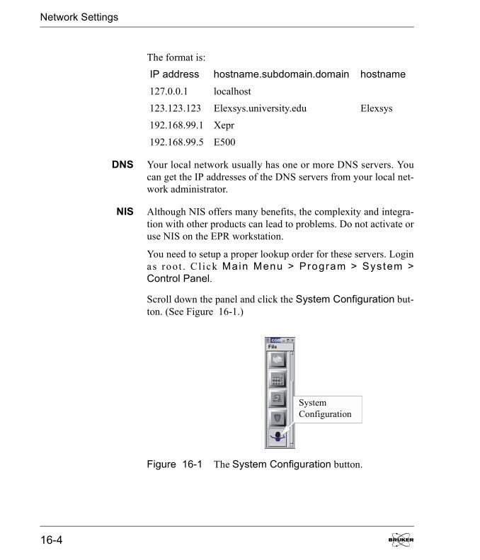
Network Settings
The format is:
IP address hostname.subdomain.domain hostname127.0.0.1 localhost
123.123.123 Elexsys.university.edu Elexsys
192.168.99.1 Xepr
192.168.99.5 E500
DNS Your local network usually has one or more DNS servers. Youcan get the IP addresses of the DNS servers from your local net-work administrator.
NIS Although NIS offers many benefits, the complexity and integra-tion with other products can lead to problems. Do not activate oruse NIS on the EPR workstation.
You need to setup a proper lookup order for these servers. Loginas root . C l ick Main Menu > Program > System >Control Panel.
Scroll down the panel and click the System Configuration but-ton. (See Figure 16-1.)
Figure 16-1 The System Configuration button.
SystemConfiguration
16-4

Network Settings
On the left part of the window click Networking > Client tasks> Host name search path. The Name service access panelappears on the right side of the window. Select hosts, dns orhosts if you do not have a DNS server. (See Figure 16-2.) Clickthe Accept button at the bottom of the window and then clickAct/Changes on the left. Click Quit to exit the System Con-figuration window.
Figure 16-2 Name service access.
Elexsys E 500 User�s Manual: Advanced Operations 16-5

Network Settings
Routing 16.2.4Although the EPR workstation has two Ethernet cards and isable to function as a router, doing so will jeopardize the commu-nication between the workstation and the EPR acquisitionserver. Modification of the routing table could also direct net-work traffic to eth1, which would slow down the response of theXepr program or even cause the Xepr program to hang up.
16-6

Linux Workstation Service Configuration
Linux Workstation Service Configuration 16.3
Flags 16.3.1Flags are used to activate and deactivate various services that theworkstation can offer. Here is the default configuration of theLinux workstation as delivered by Bruker. You can check theconfiguration by typing /sbin/chkconfig --list in a shell win-dow. The command will list all the flag statuses under all run-ning levels. Check the flag statuses under level five. tftp andbootps under xinetd based services, network, and nfs ser-vices must be on to allow the workstation to boot and communi-cate with the acquisition server properly. Although you can turnon more services than the default configuration, keep in mindthat the more services you turn on, especially network relatedservices, the slower the workstation responds. You may alsoneed to turn off some services to increase the security. Table16-1 shows a default service configuration for Red HatLinux 7.0. The nameserv and sophed flags are for the XSopheprogram. If you do not have XSophe installed you may not havethese services.
Flag Status Flag Status
syslog 5:on anacron 5:on
crond 5:on httpd 5:on
netfs 5:on apmd 5:on
network 5:on arpwatch 5:off
random 5:on atd 5:on
rawdevices 5:on named 5:off
xfs 5:on keytable 5:on
Table 16-1 Standard configuration for workstation services running under level five.
Elexsys E 500 User�s Manual: Advanced Operations 16-7
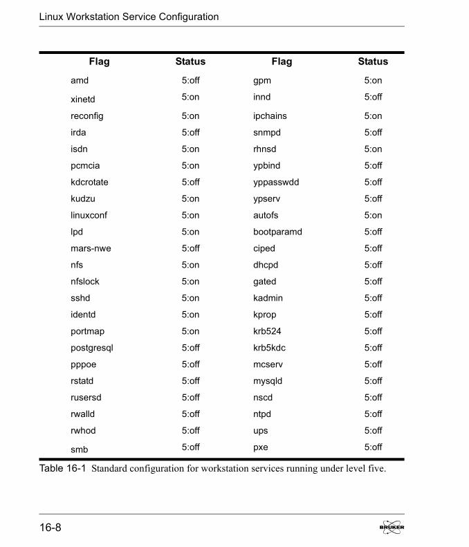
Linux Workstation Service Configuration
amd 5:off gpm 5:on
xinetd 5:on innd 5:off
reconfig 5:on ipchains 5:on
irda 5:off snmpd 5:off
isdn 5:on rhnsd 5:on
pcmcia 5:on ypbind 5:off
kdcrotate 5:off yppasswdd 5:off
kudzu 5:on ypserv 5:off
linuxconf 5:on autofs 5:on
lpd 5:on bootparamd 5:off
mars-nwe 5:off ciped 5:off
nfs 5:on dhcpd 5:off
nfslock 5:on gated 5:off
sshd 5:on kadmin 5:off
identd 5:on kprop 5:off
portmap 5:on krb524 5:off
postgresql 5:off krb5kdc 5:off
pppoe 5:off mcserv 5:off
rstatd 5:off mysqld 5:off
rusersd 5:off nscd 5:off
rwalld 5:off ntpd 5:off
rwhod 5:off ups 5:off
smb 5:off pxe 5:off
Flag Status Flag Status
Table 16-1 Standard configuration for workstation services running under level five.
16-8

Linux Workstation Service Configuration
sendmail 5:on rarpd 5:off
routed 5:off nameserv 5:on
squid 5:off sophed 5:on
vncserver 5:off
xinetd based services:
amandaidx: off comsat: off
amidxtape: off imap: off
finger: on imaps off
linuxconf-web: off ipop2 off
rexec: off ipop3 off
rlogin: on pop3s off
rsh: on eklogin: off
swat: off gssftp: off
ntalk: off klogin: off
talk: off krb5-telnet: off
telnet: on kshell: off
tftp: on bootps: on
wu-ftpd: on
Flag Status Flag Status
Table 16-1 Standard configuration for workstation services running under level five.
Elexsys E 500 User�s Manual: Advanced Operations 16-9
Linux Workstation Service Configuration
Type chkconfig --add <name> to turn the service on where<name> is the service name. Type chkconfig --del <name> toturn off the service. You may need to indicate the run level byusing the shell command:
chkconfig [--level <levels>] <name> <on|off|reset>.
Activate the service by the shell command:
service <name> start
or
service <name> restart
or rebooting the workstation.
16-10
Linux Workstation Service Configuration
Swap Space 16.3.2The best way to determine the optimal swap space size is to tryseveral sizes. The swap space size we recommend is four timesthe RAM size. When the swap space is not large enough therewill be an error message in the /var/log/messages file. If youroutinely process several large 2D datasets in Xepr you mayneed to increase your swap space. There are two types of swapspace: the swap partition and the swap file. The swap file isslower than the swap partition. To increase the swap partitionsize you need to repartition the hard drive which wipes out thecontents of the hard disk.
Security 16.3.3Functionality, accessibility, and convenience may compromisethe system security. Balancing these considerations is not a sim-ple job. Refer to the workstation administrative manual for secu-rity settings that best suit you. We suggest the following.
Lock accounts There are a few accounts such as the nobody and lp accountsutilized by Xepr and other application programs. Never deletethe nobody and lp accounts. Instead, lock these accounts andother �open to the public� accounts.
Root and SuperUser
Avoid logging in as root or super user. Only do so when youmust perform system administration tasks. Most tasks can beperformed by logging in as a normal user and then switching toroot by using the su - shell command. You should always runXepr from a normal user account except for testing or diagnosis.
Service AccessControl
You can control network access to tighten security. However,you need to be very careful not to block access for the acquisi-tion server. Here is an extreme case where most services areblocked to all clients except the acquisition server. Modify thefile /etc/xinetd.conf by adding the following line to the default{} section:
Elexsys E 500 User�s Manual: Advanced Operations 16-11

Linux Workstation Service Configuration
only_from = 192.168.99.0/24
where 192.168.99.0 is the subnet address assigned to the ACPUwhen the acquisition server was installed. If a different subnetaddress is set in the ServerSetup file you need to use it toreplace the above IP address. 24 is the number of bits for the net-work and subnetwork. However, if you make the above change,y o u m u s t a p p e n d t h e f o l l o w i n g l i n e t o t h e f i l e/etc/xinetd.d/bootps:
only_from = 0.0.0.0/0
Otherwise, the acquisition server will not boot.
You can put addresses of any trusted hosts/subnet in this entryseparated by space so that these hosts can access the servicescontrolled by xinetd.
There are many ways to tighten security. Bear in mind that anysecurity settings must allow the acquisition server to accessbootp, tftp, NFS, and other services.
16-12
Reinstalling or Upgrading Xepr
Reinstalling or Upgrading Xepr 16.4
List of Important Files 16.4.1The following files are very important and must be backed upbefore you reinstall the operating system or the Xepr software.
License File /usr/xepr/sharedSetup/license.dat
or
/usr/Bruker/flexlm/licenses/license.dat
Hall ProbeCalibration File
/ us r / xep r /Acqu is i t i onServe r /OS9/Serve rs/FUSETUP/FUEr032t/hall####.cal and hall####.dat (where#### is the serial number.)
ACPU Information /usr/xepr/AcquisitionServer/admin/ServerSetup
Signal ChannelCalibration Files
/usr/xepr/AcquisitionServer/OS9/Servers/<Server name: e.g.E500, E580, etc.>/FUSETUP/FUSct/CalibData/*.cal
Spectrometer.iniFile
/usr/xepr/Acquis i t ionServer/OS9/Servers/<Servername>/Spectrometer.ini
Pulse SystemConfiguration
Files
If you have an E 580 or E 680: /usr/xepr/Acquisition-Server /OS9/Serve rs /< S e r v e rname>/FUSETUP/FUFTEpr/XBand (and/or WBand)/*.cfg
Elexsys E 500 User�s Manual: Advanced Operations 16-13
Reinstalling or Upgrading Xepr
Performing an Installation or Upgrade 16.4.21. Check the current version of Xepr. Use the shell
command Xepr -i to determine the version of the cur-rently installed Xepr software.
2. Follow the instructions in the release note. Loginas root to install Xepr. Read the release note on the XeprCD first. Follow the instructions for installing Xepr. Usethe default installation settings to avoid any unforeseenproblems. Sometimes you may need to delete the/usr/xepr folder before you install the Xepr software.
3. Restore the backed up files. Put the files you backedup in Section 16.4.1 into the folders from which theycame.
4. Install the acquisition server. Each time you reinstallXepr or upgrade the acquisition package you must rein-stall the acquisition server. The acquisition server installa-t i o n s c r i p t i s l o c a t e d i n t h e f o l d e r/usr/xepr/AcquisitionServer/admin/. Make sure youhave the correct ServerSetup file. Change to the abovedirectory and type ./installServer to install the acquisi-tion server.
5. Reboot the UNIX workstation. If you do not, theupgrade or installation will not work properly.
16-14

Initial Setup of Xepr
Initial Setup of Xepr 16.5
Creating a New User Account 16.5.1Normally users have their own accounts. A user�s account has auser�s account name, user ID, and a password to log into theaccount. As root you can create a new user account by typinguseradd <newUserName>; passwd <newUserName> in ashell window. It will prompt you for the password. Enter andconfirm the temporary password for the new user. Linux createsa private group for the new user account. You can add the newu s e r t o t h e d e f a u l t users g r o u p b y t y p i n gusermod -G users <newUserName> in a shell window. Werecommend adding all users to the users group so that they canshare their files. If you prefer to use a GUI refer to the corre-sponding manual to find out how to create a new account. Makesure the new account is in the users group. After new users loginto their account, they can customize the desktop, windows,UNIX shell type, and other features. They should change theirpassword the first time login. Refer to the Integrated Help Sys-tem for details on configuring the account. When running Xeprfor the first time in the new account, Xepr will automaticallyconfigure its home directory to set up Xepr.
Elexsys E 500 User�s Manual: Advanced Operations 16-15
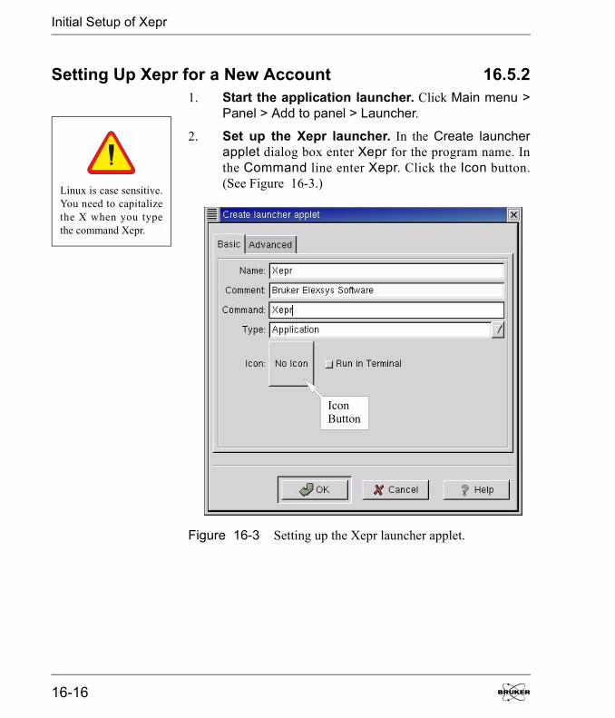
Initial Setup of Xepr
Setting Up Xepr for a New Account 16.5.21. Start the application launcher. Click Main menu >
Panel > Add to panel > Launcher.
2. Set up the Xepr launcher. In the Create launcherapplet dialog box enter Xepr for the program name. Inthe Command line enter Xepr. Click the Icon button.(See Figure 16-3.)
Figure 16-3 Setting up the Xepr launcher applet.
Linux is case sensitive.You need to capitalizethe X when you typethe command Xepr.
IconButton
16-16
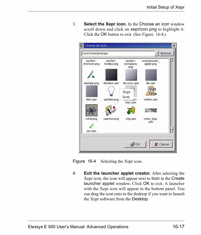
Initial Setup of Xepr
3. Select the Xepr icon. In the Choose an icon windowscroll down and click on xeprIcon.png to highlight it.Click the OK button to exit. (See Figure 16-4.)
4. Exit the launcher applet creator. After selecting theXepr icon, the icon will appear next to Icon in the Createlauncher applet window. Click OK to exit. A launcherwith the Xepr icon will appear in the bottom panel. Youcan drag the icon onto to the desktop if you want to launchthe Xepr software from the Desktop.
Figure 16-4 Selecting the Xepr icon.
XeprIcon
Elexsys E 500 User�s Manual: Advanced Operations 16-17
Initial Setup of Xepr
5. Start the Xepr application for the first time. Singleclick the Xepr icon in the bottom panel or double click theXepr icon on the desktop. The Xepr program will auto-matically configure your account to run Xepr and launchthe Xepr program. You can perform the same operationdirectly from a shell. Simply type Xepr in a shell.
Linux is case sensitive.You need to capitalizethe X when you typethe she l l commandXepr.
16-18

Initial Setup of Xepr
Setting Up the Properties of the Xepr Software 16.5.31. Maximize the Xepr window. Since Xepr has so many
components, a full screen window is recommended. Clickthe maximize button on the right top corner.
2. Select the monitoring panel position. First makesure the spectrometer is on and booted. You can chooseeither to put the monitoring panel above or below theViewport. Click the Properties button in the menu bar,and then Panel Properties. A dialog window will appear.Cl ick ei ther Top or Bottom and then OK . (SeeFigure 16-5.)
Figure 16-5 Selecting the monitoring panel position.
PanelProperties
MonitoringPosition
Elexsys E 500 User�s Manual: Advanced Operations 16-19

Initial Setup of Xepr
3. Connect to spectrometer. Click Acquisition in themenu bar and then Connect To Spectrometer. A dialogbox will appear prompting for the Server Name. Enterthe acquisition server�s name in the blank box and clickOK. (See Figure 16-6.) If you do not know the acquisi-tion server�s name, ask the system administrator. The typ-ical servers names are e500, e580, e600, or e680,depending on the type of spectrometer.
Figure 16-6 Connecting to the spectrometer.
EnterServerName
16-20
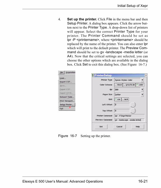
Initial Setup of Xepr
4. Set up the printer. Click File in the menu bar and thenSetup Printer. A dialog box appears. Click the arrow but-ton next to the Printer Type. A drop-down list of printerswill appear. Select the correct Printer Type for yourprinter. The Printer Command should be set aslpr -P <printername>, where <printername> should bereplaced by the name of the printer. You can also enter lprwhich will print to the default printer. The Preview Com-mand should be set to gv -landscape -media letter (orA4). Now that the critical settings are selected, you canchoose the other options which are available in the dialogbox. Click Set to exit this dialog box. (See Figure 16-7.)
Figure 16-7 Setting up the printer.
Elexsys E 500 User�s Manual: Advanced Operations 16-21

Initial Setup of Xepr
5. Test the printer. Load an EPR spectrum. Display thespectrum in the viewport. Click Print in the Filedrop-down menu. A dialog box appears. Select the properOrientation, Width, Height, and other parameters. Clickprinter as the Destination. Click the Print button. (SeeFigure 16-8.)
6. Disconnect from the spectrometer. Click Acquisi-tion > Disconnect From Spectrometer. The monitoringpanel will disappear.
Figure 16-8 Testing the printer.
PrintViewport
16-22
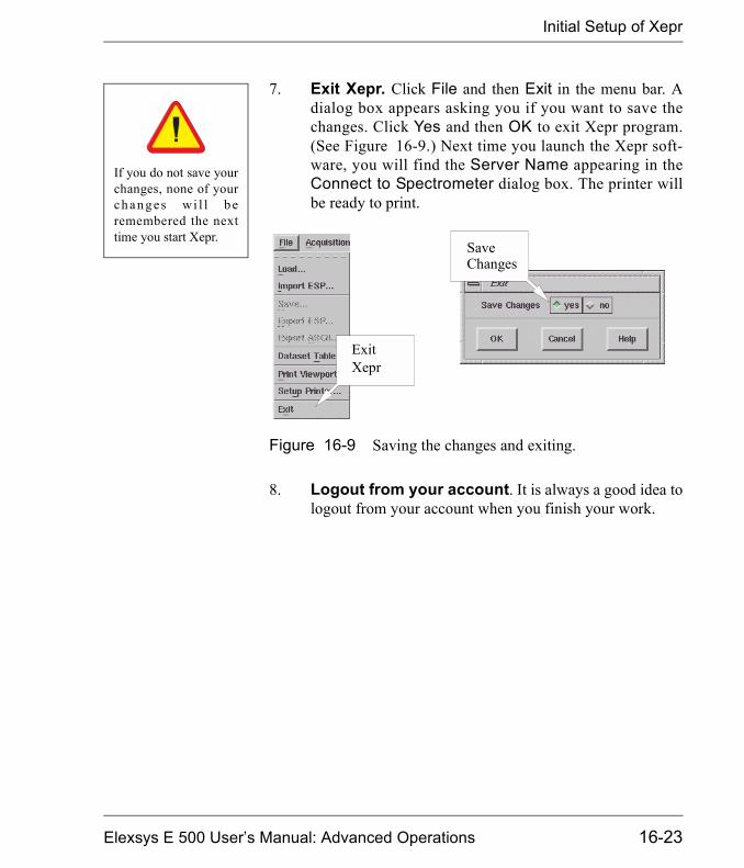
Initial Setup of Xepr
7. Exit Xepr. Click File and then Exit in the menu bar. Adialog box appears asking you if you want to save thechanges. Click Yes and then OK to exit Xepr program.(See Figure 16-9.) Next time you launch the Xepr soft-ware, you will find the Server Name appearing in theConnect to Spectrometer dialog box. The printer willbe ready to print.
8. Logout from your account. It is always a good idea tologout from your account when you finish your work.
Figure 16-9 Saving the changes and exiting.
If you do not save yourchanges, none of yourch a n g es wi l l b eremembered the nexttime you start Xepr.
ExitXepr
SaveChanges
Elexsys E 500 User�s Manual: Advanced Operations 16-23
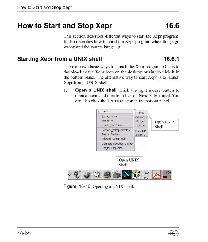
How to Start and Stop Xepr
How to Start and Stop Xepr 16.6This section describes different ways to start the Xepr program.It also describes how to abort the Xepr program when things gowrong and the system hangs up.
Starting Xepr from a UNIX shell 16.6.1There are two basic ways to launch the Xepr program. One is todouble-click the Xepr icon on the desktop or single-click it inthe bottom panel. The alternative way to start Xepr is to launchXepr from a UNIX shell.
1. Open a UNIX shell. Click the right mouse button toopen a menu and then left click on New > Terminal. Youcan also click the Terminal icon in the bottom panel.
Figure 16-10 Opening a UNIX shell.
Open UNIXShell
Open UNIXShell
16-24
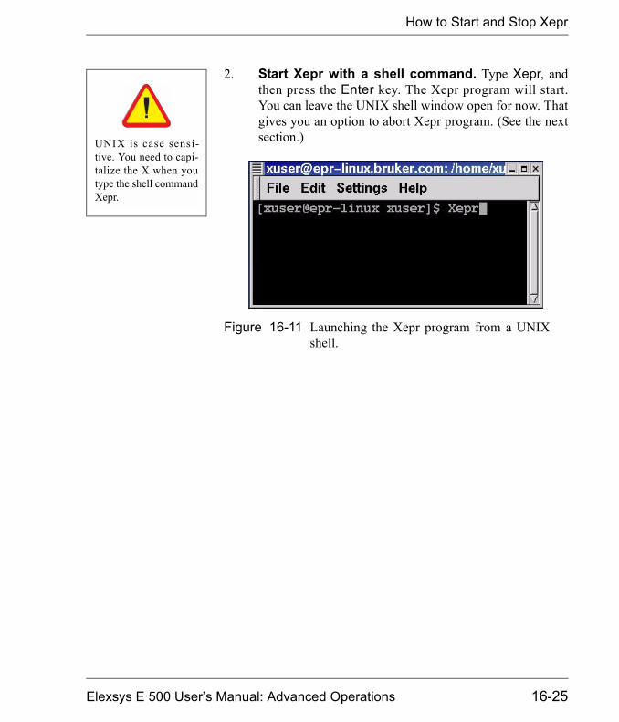
How to Start and Stop Xepr
2. Start Xepr with a shell command. Type Xepr, andthen press the Enter key. The Xepr program will start.You can leave the UNIX shell window open for now. Thatgives you an option to abort Xepr program. (See the nextsection.)
Figure 16-11 Launching the Xepr program from a UNIXshell.
UNIX is case sensi-tive. You need to capi-talize the X when youtype the shell commandXepr.
Elexsys E 500 User�s Manual: Advanced Operations 16-25
Aborting Xepr
Aborting Xepr 16.7Normally you need to exit Xepr by clicking File in the menu bar,and then clicking Exit to terminate the Xepr program. However,when something goes wrong or the system hangs up, you maynot be able to exit Xepr by normal methods. Keep in mind,sometimes Xepr needs more time to execute certain functionsespecially the communications between the system and slowdevices. It may not respond to your command instantly. GiveXepr some extra time. Avoid continuously clicking the mousebutton: it only make the system even busier. When memory isrunning too low or there is too much network traffic, Xepr mighthang up. Keep clearing up the Result Dataset. Avoid loadingtoo many large data files into Xepr. Reduce network activitiesparticularly when you connect to the spectrometer. These thingswill help you reduce the possibility of hanging up. If you fail toclose Xepr in the normal way, we suggest the following. First trythe normal procedure to exit Xepr. If that fails, try aborting bythe methods described in this section. After you abort Xepr, turnoff the console and turn on the console again before you recon-nect to spectrometer.
Logout from the Current Account. 16.7.1This is the easiest way to abort Xepr. Simply follow the logoutprocedure described in Appendix B of the Elexsys User�s Man-ual: Basic Operations and the Xepr program will be terminated.
The Ctrl-C command 16.7.2If you start the Xepr program from a UNIX shell, you can alsouse the Ctrl-C command to abort Xepr program. Minimize(iconize) the Xepr window. Move the mouse pointer inside theUNIX shell window from which you launched Xepr program.Press the <Ctrl> key and the c key simultaneously. The Xepr
16-26
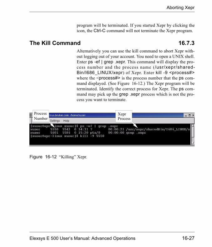
Aborting Xepr
program will be terminated. If you started Xepr by clicking theicon, the Ctrl-C command will not terminate the Xepr program.
The Kill Command 16.7.3Alternatively you can use the kill command to abort Xepr with-out logging out of your account. You need to open a UNIX shell.Enter ps -ef | grep .xepr. This command will display the pro-cess number and the process name (/usr/xepr/shared-Bin/I686_LINUX/xepr) of Xepr. Enter kill -9 <process#>where the <process#> is the process number that the ps com-mand displayed. (See Figure 16-12.) The Xepr program will beterminated. Identify the correct process for Xepr. The ps com-mand may pick up the grep .xepr process which is not the pro-cess you want to terminate.
Figure 16-12 �Killing� Xepr.
ProcessNumber
XeprProcess
Elexsys E 500 User�s Manual: Advanced Operations 16-27

The Xepr Printer
The Xepr Printer 16.8
Installing a Printer 16.8.1The printer coming with the spectrometer should already beinstalled and configured when the Elexsys spectrometer wasinstalled. If you have printing problems with the Xepr program,first check the printer setup described in Section 16.5.3, Step 4.You may also consult in the Linux documentations about theprinter. If the problem still exists you can follow these instruc-tions to reinstall the printer. Make sure the printer is physicallyconnected before you start.
1. Launch the Print System Manager. Login as root.Click Main Menu > Programs > System > ControlPanel, and then the Print System Manager button. (SeeFigure 16-13.)
Figure 16-13 Starting the print system manager.
Check if your printer isconnected, turned on,and on-line.
PrintSystemManager
16-28

The Xepr Printer
2. Delete the printer that does not work. If the listedprinter does not work, select it by clicking its entry withthe left mouse button and then click the Delete button.(See Figure 16-14.).
3. Add a new printer. Click the Add button in the dialogbox and a dialog box for adding a new printer appears.(See Figure 16-15.) Select Local Printer and click OK.
Figure 16-14 The Print System Manager dialog box.
Figure 16-15 Adding a new printer.
AddButton
DeleteButton
Elexsys E 500 User�s Manual: Advanced Operations 16-29

The Xepr Printer
4. Identify the printing device. An info box appears tell-ing you what printing devices are detected. If no device isdetected, check the hardware and its connections. Other-wise, click OK to close this window. (See Figure 16-16.)
Figure 16-16 Info window identifying printing devices.
16-30
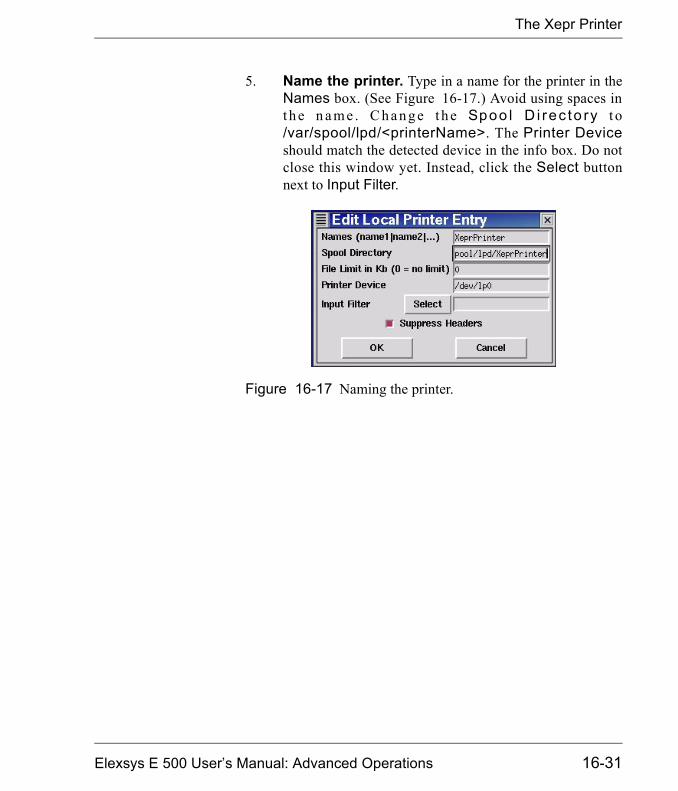
The Xepr Printer
5. Name the printer. Type in a name for the printer in theNames box. (See Figure 16-17.) Avoid using spaces int h e n a m e . C h a n g e t h e Spoo l D i rec to ry t o/var/spool/lpd/<printerName>. The Printer Deviceshould match the detected device in the info box. Do notclose this window yet. Instead, click the Select buttonnext to Input Filter.
Figure 16-17 Naming the printer.
Elexsys E 500 User�s Manual: Advanced Operations 16-31

The Xepr Printer
6. Configure the filter. In the Configure Filter windowselect the proper printer model. On the right side of thewindow, select the desired Paper Size and ColorDepth/Uniprint Mode. Also make your PrintingOptions choices. These options may need to be set differ-ently for different printers. Usually choosing all threeoptions works. After you finish configuring the filter,click OK to exit. (See Figure 16-18.)
Figure 16-18 Configuring the filter.
PrinterType
PaperSize
Color Depth/Uniprint Mode
PrintingOptions
16-32

The Xepr Printer
7. Exit Local Printer Entry. The filter you configured willautomatically fill in the Input Filter box in the LocalPrinter Entry window. Click OK button to exit. (SeeFigure 16-19.)
8. Restart lpd. In the Print System Manager windowclick lpd > Restart lpd. (See Figure 16-20.)
Figure 16-19 Closing the Local Printer Entry window.
Figure 16-20 Restarting lpd.
Elexsys E 500 User�s Manual: Advanced Operations 16-33
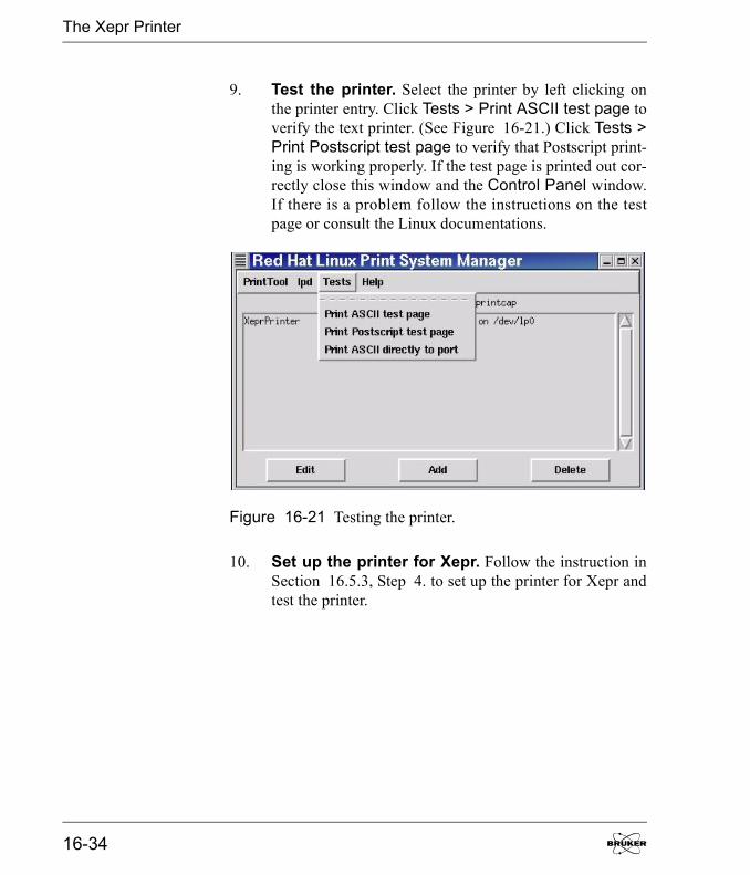
The Xepr Printer
9. Test the printer. Select the printer by left clicking onthe printer entry. Click Tests > Print ASCII test page toverify the text printer. (See Figure 16-21.) Click Tests >Print Postscript test page to verify that Postscript print-ing is working properly. If the test page is printed out cor-rectly close this window and the Control Panel window.If there is a problem follow the instructions on the testpage or consult the Linux documentations.
10. Set up the printer for Xepr. Follow the instruction inSection 16.5.3, Step 4. to set up the printer for Xepr andtest the printer.
Figure 16-21 Testing the printer.
16-34
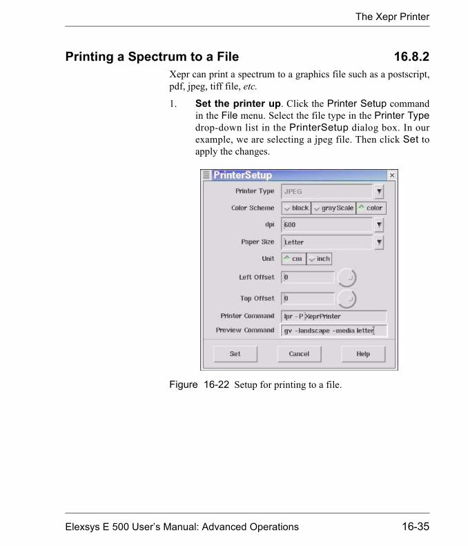
The Xepr Printer
Printing a Spectrum to a File 16.8.2Xepr can print a spectrum to a graphics file such as a postscript,pdf, jpeg, tiff file, etc.
1. Set the printer up. Click the Printer Setup commandin the File menu. Select the file type in the Printer Typedrop-down list in the PrinterSetup dialog box. In ourexample, we are selecting a jpeg file. Then click Set toapply the changes.
Figure 16-22 Setup for printing to a file.
Elexsys E 500 User�s Manual: Advanced Operations 16-35
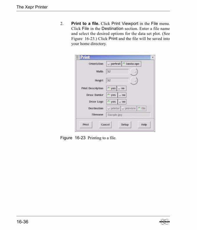
The Xepr Printer
2. Print to a file. Click Print Viewport in the File menu.Click File in the Destination section. Enter a file nameand select the desired options for the data set plot. (SeeFigure 16-23.) Click Print and the file will be saved intoyour home directory.
Figure 16-23 Printing to a file.
16-36

The Xepr Printer
Print Preview 16.8.3You can preview your plot first before you print a hard copy orprint to a file. Select preview from the Destination buttons. Thecontents in the selected viewport will be sent to ghostview fordisplay. (See Figure 16-24.)
Figure 16-24 Previewing with ghostview.
Elexsys E 500 User�s Manual: Advanced Operations 16-37
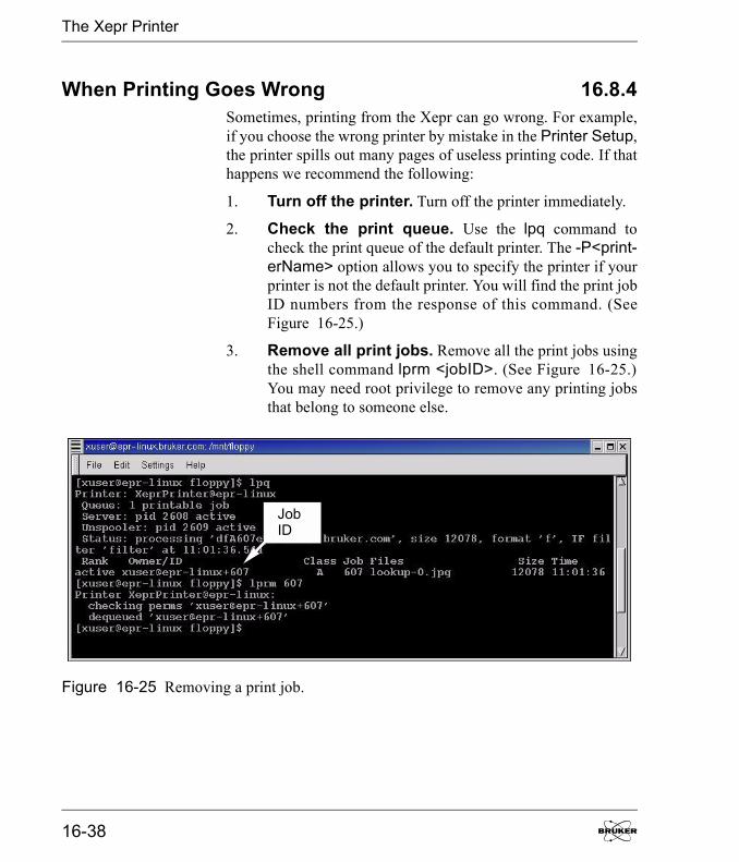
The Xepr Printer
When Printing Goes Wrong 16.8.4Sometimes, printing from the Xepr can go wrong. For example,if you choose the wrong printer by mistake in the Printer Setup,the printer spills out many pages of useless printing code. If thathappens we recommend the following:
1. Turn off the printer. Turn off the printer immediately.
2. Check the print queue. Use the lpq command tocheck the print queue of the default printer. The -P<print-erName> option allows you to specify the printer if yourprinter is not the default printer. You will find the print jobID numbers from the response of this command. (SeeFigure 16-25.)
3. Remove all print jobs. Remove all the print jobs usingthe shell command lprm <jobID>. (See Figure 16-25.)You may need root privilege to remove any printing jobsthat belong to someone else.
Figure 16-25 Removing a print job.
JobID
16-38

The Xepr Printer
4. Check the printer setup. Carefully follow the instruc-tions described in Section 16.5.3, Step 4. to make surethe printer is set up correctly. You may need to reinstallthe printer. (See Section 16.8.1.)
5. Stop printing the many pages. You may be able tostop the flood of paper with useless code by disconnectingthe printer cable from the workstation, turning on theprinter, and then reconnecting the printer cable.
Make sure you haveselected the correctprinter in the PrinterSetup of Xepr.
Elexsys E 500 User�s Manual: Advanced Operations 16-39
Networking & Remote Operation
Networking & Remote Operation 16.9The Elexsys E 500 series EPR spectrometer is designed to oper-ate in a networked environment. The workstation is equippedwith two Ethernet cards. The primary network adapter (eth0)connects the workstation to the outside network. The secondarynetwork adapter (eth1) is solely dedicated to communicationbetween the workstation and the acquisition server of the EPRspectrometer. This client/server architecture resolves the conflictbetween multi-user/multi-tasking on the one hand and real-timefunctionality on the other hand. Therefore, multiple users fromdifferent locations are able to access Xepr remotely. However,excessive communication between the workstation and the out-side world not only slows down the Xepr program but alsoopens the door for unauthorized access. Although the worksta-tion is capable of functioning as a general network server it ishighly recommended to use the Elexsys EPR workstation foracquiring EPR spectra only. The administrator of the worksta-tion needs to carefully balance the security of the Elexsys work-station and public network access. This section discusses datatransfer through the network and remote login to the work sta-tion.
Remote Access to Xepr 16.9.1You can log onto the workstation remotely, allowing multipleusers access to the Xepr software at the same time. Each userremotely logs into the workstation and launches the Xepr soft-ware. In the following section we refer to the workstationdirectly connected to the Elexsys spectrometer as the EPR serverand the other computers connected to the EPR server throughnetwork as clients.
16-40

Networking & Remote Operation
Remote Logon to the EPR Server 16.9.2The client and the EPR server should be assigned appropriate IPaddresses and connected to the same network. The primary net-work connection (eth0) of the EPR server should be used toconnect to the network. In order to display the Xepr applicationwindow on the client�s monitor, you must either activate remotedisplay on the client computer (if the client has a UNIX operat-ing system) or use special software, such as PC-Xware (if theoperating system is Windows). You also need a valid useraccount on the EPR server.
From a UNIXSystem
On the client computer, remote display is enabled by executingthe shell command,
xhost + <EPR server’s IP address>
In the shell window, enter
telnet <EPR server IP address>
Enter the user�s name and password when you are prompted.After logging into the EPR server, type Xepr to launch the Xeprprogram.
From a WindowsSystem
Refer to the documentation for your X-terminal application fordetails on enabling remote display.
After you remotely launch the Xepr program you can execute allthe Xepr functions.
Elexsys E 500 User�s Manual: Advanced Operations 16-41
Networking & Remote Operation
Remote Control of the Spectrometer 16.9.3You can also control the EPR spectrometer remotely. Make surethere are no other Xepr users connected to the spectrometer.Click Acquisition > Connect to Spectrometer after youlaunch the Xepr program remotely. In the dialog box, enter thename of the spectrometer and then click Connect. Spectrometercontrol operations including tuning, acquiring spectra, etc. arenow available to you through the Xepr software. Note that onlyone instance of the Xepr application can connect to the spec-trometer at a time. After one connection is established, all otherconnections are blocked.
Data Transfer Via the Network 16.9.4There are several ways to transfer data between the workstationand other computers connected to the network.
FTP FTP (File Transfer Protocol) is one of the most commonly usedmethods for data transfer. Elexsys data files are in BES3T® for-mat. Each EPR spectrum consists of a binary data file with a*.DTA extension and an ASCII description file with a *.DSCextension. You must select binary transfer mode to transfer*.DTA files properly.
SAMBA SAMBA is an option for data sharing with the Microsoft Win-dows and other platforms.
NFS NFS (Network File System) can be configured on your worksta-tion for data sharing with other UNIX workstations. There arealso versions of NFS that run on Windows and Mac platforms.
16-42

Acquisition Server Diagnostics 17The Elexsys E 500 series EPR spectrometer is a multi-computersystem. It consists of a UNIX workstation, an OS9 acquisitionserver CPU (ACPU), and a transputer for each transputer con-trolled device. Normally, when you turn the console on, every-thing boots up and initializes in an orderly fashion. This chapterdescribes what to do in the unlikely event that it does not.
Elexsys E 500 User�s Manual: Advanced Operations
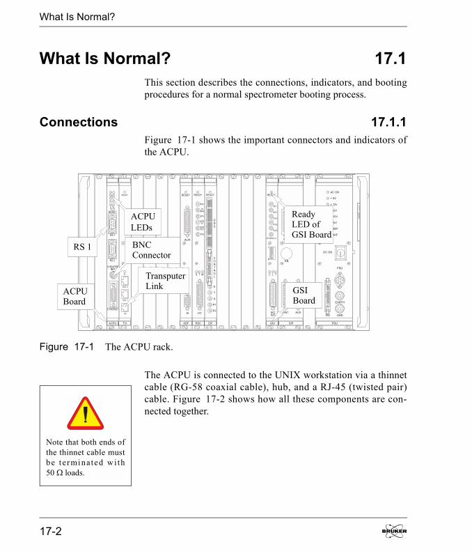
What Is Normal?
What Is Normal? 17.1This section describes the connections, indicators, and bootingprocedures for a normal spectrometer booting process.
Connections 17.1.1Figure 17-1 shows the important connectors and indicators ofthe ACPU.
The ACPU is connected to the UNIX workstation via a thinnetcable (RG-58 coaxial cable), hub, and a RJ-45 (twisted pair)cable. Figure 17-2 shows how all these components are con-nected together.
Figure 17-1 The ACPU rack.
ACPUBoard
ACPULEDs
ReadyLED ofGSI Board
TransputerLink
BNCConnector
RS 1
GSIBoard
Note that both ends ofthe thinnet cable mustbe t erminated wi th50 � loads.
17-2

What Is Normal?
See Section 13.2.4 for information regarding the transputer con-nections.
Figure 17-2 The Ethernet connections.
ACPU
Hub
UnixWorkstation
50 OhmTerminator
BNCT-Connector
RG58CoaxCable
TwistedPairCable
BNCConnector
SecondaryEthernetCard
50 OhmTerminator
(ec1 or eth1)
Elexsys E 500 User�s Manual: Advanced Operations 17-3
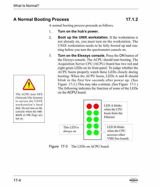
What Is Normal?
A Normal Booting Process 17.1.2A normal booting process proceeds as follows.
1. Turn on the hub�s power. 2. Boot up the UNIX workstation. If the workstation is
not already on, you must turn on the workstation. TheUNIX workstation needs to be fully booted up and run-ning before you turn the spectrometer console on.
3. Turn on the Elexsys console. Press the ON button ofthe Elexsys console. The ACPU should start booting. TheAcquisition Server CPU (ACPU) board has two red andeight green LEDs on its front panel. To judge whether theACPU boots properly watch these LEDs closely duringbooting. When the ACPU boots, LEDs A and B shouldblink in the first few seconds after power up. (SeeFigure 17-3.) This may take a minute. (See Figure 17-1.)The following indicates the function of some of the LEDson the ACPU board.
Figure 17-3 The LEDs on ACPU board.
The ACPU uses NFS(Network File System)to access the UNIXworks t a t i on�s ha rddisk. Do not turn on theconsole when the net-work or nfs flags arenot on.
LED A blinkswhen the CPUboots from theEthernet
LED B blinkswhen the CPUaccesses otherVME-bus boards
This LED isalways on
17-4
What Is Normal?
4. Boot up the transputer devices. After the ACPUboots up from the UNIX workstation, it immediatelybegins to boot the transputer devices. As each device isidentified its R LED will blink once briefly. When thetransputer device is booting, the R LED blinks rapidlyabout 10 times and then stays on. Upon successful bootingof the ACPU and the transputer devices, the GSI board�sReady LED will light. (See Figure 17-1.)
5. Connect to the spectrometer. Select the Connect toSpectrometer command in the Acquisition menu.
Elexsys E 500 User�s Manual: Advanced Operations 17-5
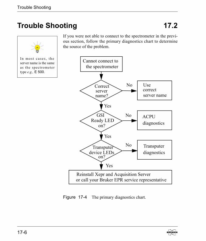
Trouble Shooting
Trouble Shooting 17.2If you were not able to connect to the spectrometer in the previ-ous section, follow the primary diagnostics chart to determinethe source of the problem.
Figure 17-4 The primary diagnostics chart.
In mo s t c a se s , t h eserver name is the sameas the spectrometertype e.g., E 500.
Cannot connect tothe spectrometer
Reinstall Xepr and Acquisition Serveror call your Bruker EPR service representative
Correctservername?
GSIReady LED
on?
Transputerdevice LEDs
on?
Usecorrectserver name
ACPUdiagnostics
Transputerdiagnostics
No
Yes
Yes
Yes
No
No
17-6
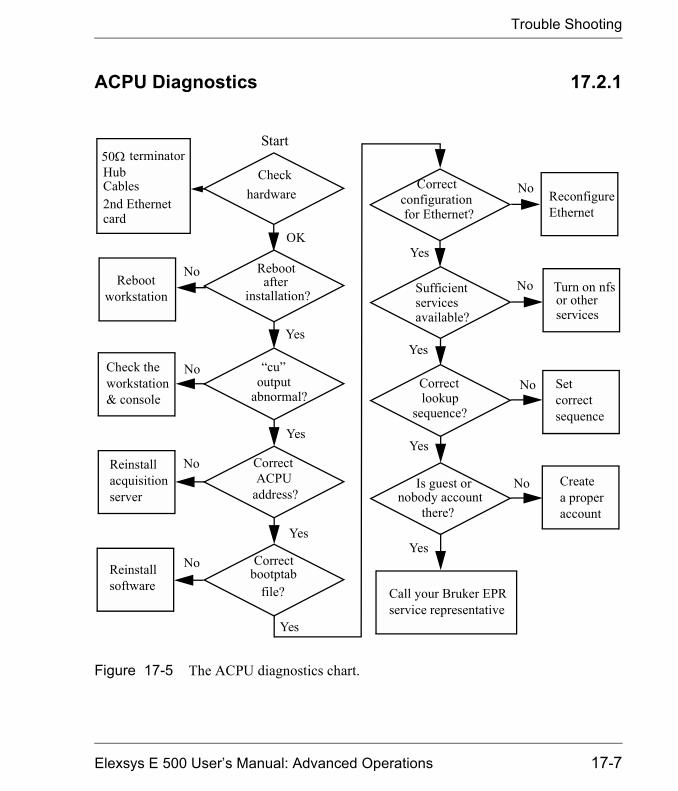
Trouble Shooting
ACPU Diagnostics 17.2.1
Figure 17-5 The ACPU diagnostics chart.
Rebootafter
installation?
ACPUaddress?
Correct
Correctbootptab
file?
Correct
for Ethernet?configuration
Correctlookup
sequence?
Check theworkstation& console
Reinstallacquisitionserver
Reinstall
Setcorrectsequence
Createa properaccount
software Call your Bruker EPRservice representative
No
Yes
No
No
No
No
No
Yes
Yes
Yes
Yes
OK
Yes
No
Yes
Rebootworkstation
�cu�
abnormal?output
ReconfigureEthernet
NoCheck
hardware
50� terminatorHubCables2nd Ethernetcard
Yes
Start
Sufficientservicesavailable?
Turn on nfsor otherservices
Is guest ornobody account
there?
Elexsys E 500 User�s Manual: Advanced Operations 17-7
Trouble Shooting
If the LED of the GSI board is not lit, it is likely that the ACPUis not booted correctly. Follow the flow chart of the ACPU diag-nostics to locate the problem.
1. Check the hardware connections.
� Check the console computer rack power supply.
� Make sure both ends of the thinnet connection areterminated with 50 loads.
� Check the power and the connection of the hub. Donot use uplink.
� Carefully inspect all the network cables and theirconnectors.
� Make sure the second ethernet card is functioningproperly.
2. Reboot the workstation after installation of theXepr software and the Acquisition Server. Youmust restart the UNIX workstation after you install Xeprand the Acquisition Server in order for the spectrometerto work properly.
3. Check the booting process. You can use the cu com-mand to check the booting process of the ACPU. Connecta terminal cable (part number E5002111) from RS1 onthe ACPU to port 2 of the SGI O2 workstation (connectorclosest to the edge) or the first (1) RS232 port of theLinux workstation. In a UNIX shell window typecu - l /dev/ t tyd2 for an SGI O2 worksta t ion o rcu -l /dev/ttyS0 for a Linux workstation. The shell willrespond �connected�. Reboot the acquisition server byeither pressing the Reset switch to the left or switch theconsole power off and on. If the ACPU boots correctly thedisplay in the shell window of the workstation monitorshould look similar to what follows.
Use the letter �el� notthe number �one� withthe cu command.
17-8
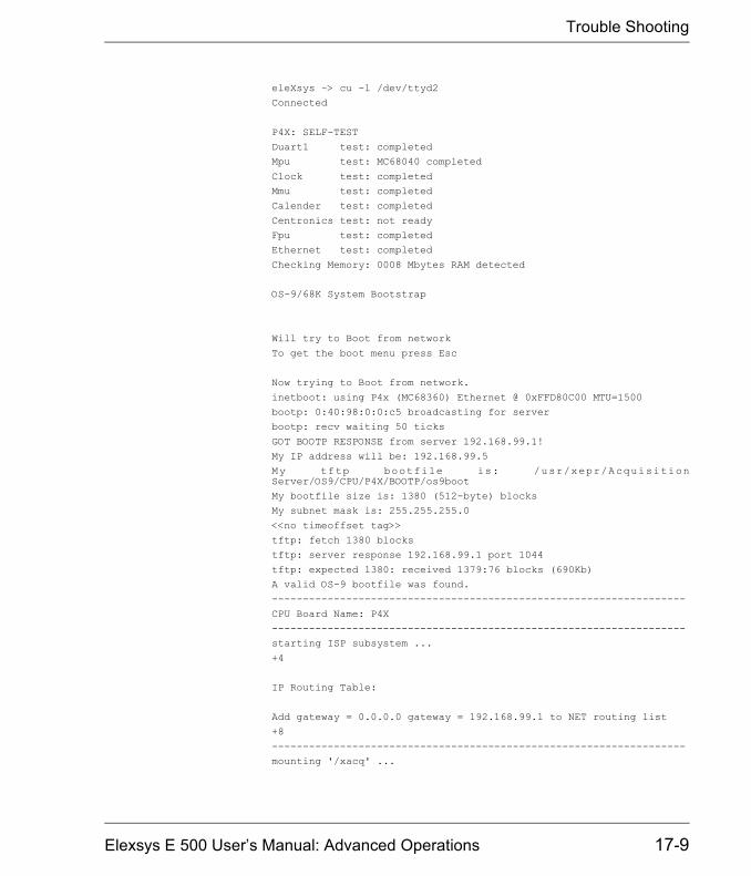
Trouble Shooting
eleXsys ~> cu -l /dev/ttyd2Connected
P4X: SELF-TESTDuart1 test: completedMpu test: MC68040 completed
Clock test: completedMmu test: completedCalender test: completed
Centronics test: not readyFpu test: completedEthernet test: completed
Checking Memory: 0008 Mbytes RAM detected
OS-9/68K System Bootstrap
Will try to Boot from network
To get the boot menu press Esc
Now trying to Boot from network.
inetboot: using P4x (MC68360) Ethernet @ 0xFFD80C00 MTU=1500bootp: 0:40:98:0:0:c5 broadcasting for serverbootp: recv waiting 50 ticks
GOT BOOTP RESPONSE from server 192.168.99.1!My IP address will be: 192.168.99.5My tftp bootfile is: /usr/xepr/AcquisitionServer/OS9/CPU/P4X/BOOTP/os9bootMy bootfile size is: 1380 (512-byte) blocksMy subnet mask is: 255.255.255.0
<<no timeoffset tag>>tftp: fetch 1380 blockstftp: server response 192.168.99.1 port 1044
tftp: expected 1380: received 1379:76 blocks (690Kb)A valid OS-9 bootfile was found.-------------------------------------------------------------------
CPU Board Name: P4X-------------------------------------------------------------------starting ISP subsystem ...
+4
IP Routing Table:
Add gateway = 0.0.0.0 gateway = 192.168.99.1 to NET routing list+8
-------------------------------------------------------------------mounting '/xacq' ...
Elexsys E 500 User�s Manual: Advanced Operations 17-9

Trouble Shooting
mounting '/dd' ...mounting '/r0' ...-------------------------------------------------------------------
Mount Status 13:17:06OS-9 Remote Gid/Uid MountDevice System Map Point
------ ------ -------- -----/xacq BootWS yes /usr/xepr/AcquisitionServer/OS9/dd BootWS yes /usr/xepr/AcquisitionServer/OS9/CPU/P4X/r0 BootWS yes /usr/xepr/AcquisitionServer/OS9/Servers/E500/r0
-------------------------------------------------------------------PROMPT=E500# PATH=/dd/CMDS
HOME=/r0AcqSvCPURootPath=/ddAcqSvRootPath=/xacq/Servers
AcqSvCPUName=P4XAcqSvHostName=E500+21
AcqSvG: 'AcqServerD' started ...-------------------------------------------------------------------
E500#
If the ACPU is not booted correctly there will be errormessages. The following demonstrates what happenswhen the ACPU hardware address is incorrect or theACPU is not connected to the UNIX workstation cor-rectly.
17-10

Trouble Shooting
Now trying to Boot from network.inetboot: using P4x (MC68360) Ethernet @ 0xFFD80C00 MTU=1500bootp: 0:40:98:0:0:c5 broadcasting for serverbootp: recv waiting 50 ticksbootp: retry 1 with new timeout=0bootp: 0:40:98:0:0:c5 broadcasting for serverbootp: recv waiting 50 ticksbootp: retry 2 with new timeout=0bootp: 0:40:98:0:0:c5 broadcasting for serverbootp: recv waiting 50 ticksbootp: retry 3 with new timeout=0bootp: 0:40:98:0:0:c5 broadcasting for serverbootp: recv waiting 50 ticksbootp: retry 4 with new timeout=30Exiting after 5 retryThis error occurred during the Internet boot boot driver!The OS-9 error code is: #007:025.
Now trying to Reconfigure the boot system.
BOOT SYSTEM RECONFIGURATION
Boot drivers available:
1 - Boot from Teac SCSI floppy drive2 - Boot from OMTI 5400 SCSI floppy drive3 - Boot from SCSI hard drive4 - Boot from SCSI tape drive5 - Boot from ROM6 - Boot from network
The priority of these boot drivers can be set below and will remainset even when power to your system is turned off. This prioritydetermines the order that the boot drivers will be selected whenyoursystem is configured to boot automatically. It also determines theorder that they appear in the "boot driver menu" as well.
The current system boot driver priority is: 6
Enter the numbers of the boot drivers in the order that you wantthem prioritized. -> that you want them prioritized. ->
Elexsys E 500 User�s Manual: Advanced Operations 17-11
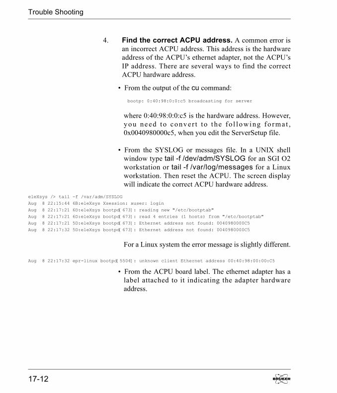
Trouble Shooting
4. Find the correct ACPU address. A common error isan incorrect ACPU address. This address is the hardwareaddress of the ACPU�s ethernet adapter, not the ACPU�sIP address. There are several ways to find the correctACPU hardware address.
� From the output of the cu command:
bootp: 0:40:98:0:0:c5 broadcasting for server
where 0:40:98:0:0:c5 is the hardware address. However,y ou ne ed to co nv er t to t he fo l lo wi ng fo rmat ,0x0040980000c5, when you edit the ServerSetup file.
� From the SYSLOG or messages file. In a UNIX shellwindow type tail -f /dev/adm/SYSLOG for an SGI O2workstation or tail -f /var/log/messages for a Linuxworkstation. Then reset the ACPU. The screen displaywill indicate the correct ACPU hardware address.
eleXsys /> tail -f /var/adm/SYSLOGAug 8 22:15:44 6B:eleXsys Xsession: xuser: login
Aug 8 22:17:21 6D:eleXsys bootpd[673]: reading new "/etc/bootptab"Aug 8 22:17:21 6D:eleXsys bootpd[673]: read 4 entries (1 hosts) from "/etc/bootptab"Aug 8 22:17:21 5D:eleXsys bootpd[673]: Ethernet address not found: 0040980000C5
Aug 8 22:17:32 5D:eleXsys bootpd[673]: Ethernet address not found: 0040980000C5
For a Linux system the error message is slightly different.
Aug 8 22:17:32 epr-linux bootpd[5504]: unknown client Ethernet address 00:40:98:00:00:C5
� From the ACPU board label. The ethernet adapter has alabel attached to it indicating the adapter hardwareaddress.
17-12
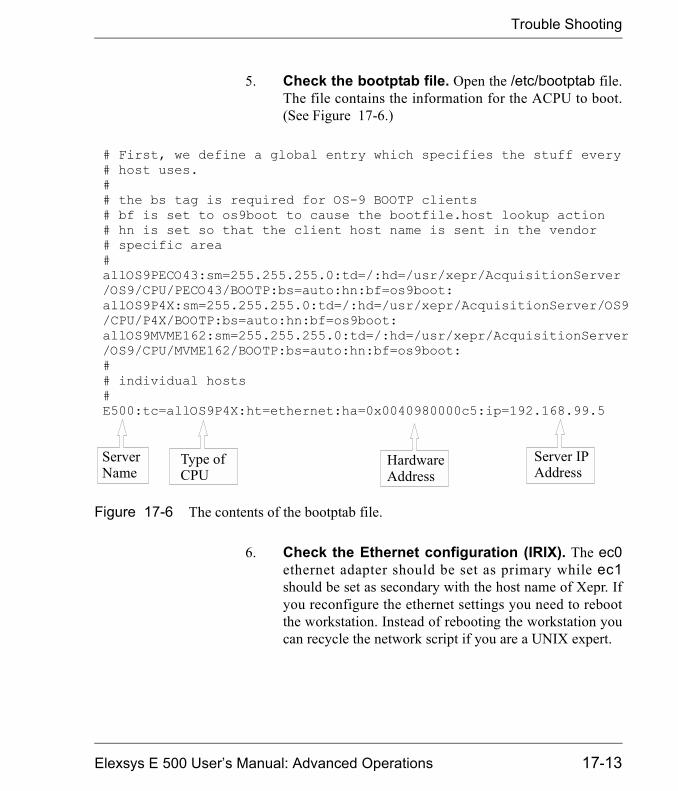
Trouble Shooting
5. Check the bootptab file. Open the /etc/bootptab file.The file contains the information for the ACPU to boot.(See Figure 17-6.)
6. Check the Ethernet configuration (IRIX). The ec0ethernet adapter should be set as primary while ec1should be set as secondary with the host name of Xepr. Ifyou reconfigure the ethernet settings you need to rebootthe workstation. Instead of rebooting the workstation youcan recycle the network script if you are a UNIX expert.
Figure 17-6 The contents of the bootptab file.
# First, we define a global entry which specifies the stuff every# host uses.## the bs tag is required for OS-9 BOOTP clients# bf is set to os9boot to cause the bootfile.host lookup action# hn is set so that the client host name is sent in the vendor # specific area#allOS9PECO43:sm=255.255.255.0:td=/:hd=/usr/xepr/AcquisitionServer/OS9/CPU/PECO43/BOOTP:bs=auto:hn:bf=os9boot:allOS9P4X:sm=255.255.255.0:td=/:hd=/usr/xepr/AcquisitionServer/OS9/CPU/P4X/BOOTP:bs=auto:hn:bf=os9boot:allOS9MVME162:sm=255.255.255.0:td=/:hd=/usr/xepr/AcquisitionServer/OS9/CPU/MVME162/BOOTP:bs=auto:hn:bf=os9boot:# # individual hosts# E500:tc=allOS9P4X:ht=ethernet:ha=0x0040980000c5:ip=192.168.99.5
Server IPAddress
ServerName
Type ofCPU
HardwareAddress
Elexsys E 500 User�s Manual: Advanced Operations 17-13

Trouble Shooting
7. Check the Ethernet configuration (Linux). Type/sbin/ifconfig in a terminal window and you will receiveinformation regarding your network settings. For exam-ple:
eth0 Link encap:Ethernet HWaddr 10:00:00:42:54:01 inet addr:137.1.7.27 Bcast:137.1.255.255 Mask:255.255.0.0
UP BROADCAST RUNNING MULTICAST MTU:1500 Metric:1 RX packets:5298627 errors:0 dropped:0 overruns:0 frame:0 TX packets:24 errors:0 dropped:0 overruns:0 carrier:0
collisions:0 txqueuelen:100 Interrupt:19 Base address:0x1080
eth1 Link encap:Ethernet HWaddr 10:00:00:42:54:02 inet addr:192.168.99.1 Bcast:192.168.99.255 Mask:255.255.255.0 UP BROADCAST RUNNING MULTICAST MTU:1500 Metric:1
RX packets:248023 errors:0 dropped:0 overruns:0 frame:0 TX packets:180600 errors:0 dropped:0 overruns:0 carrier:0 collisions:0 txqueuelen:100
Interrupt:19 Base address:0x1000
lo Link encap:Local Loopback
inet addr:127.0.0.1 Mask:255.0.0.0 UP LOOPBACK RUNNING MTU:3924 Metric:1 RX packets:139 errors:0 dropped:0 overruns:0 frame:0
TX packets:139 errors:0 dropped:0 overruns:0 carrier:0 collisions:0 txqueuelen:0
Check that the following is set for eth1:
inet addr: 192.168.99.1
Bcast: 192.168.99.255
Mask: 255.255.255.0
8. Check the services. It is crucial for the acquisitionserver to be able to access some critical services such asbootp, tftp, and nfs. If a booting problem only exists afteryou configure the services or turn off some flags, you mayhave blocked critical services from the acquisition server.Reconfigure the services or turn the flags on. The nfs flagmust be on to allow Xepr to work properly. Use chkcon-fig to check the flags. Make sure the nfs and network flags
17-14

Trouble Shooting
are on. If they are off you need to turn them on and restartthe workstation. (See Section 15.3.1 or Section 16.3.1.)
9. Check the lookup sequence. Set files as the firstchoice for the lookup sequence. Setting the NIS or DNSservers prior to files in the lookup sequence may causeACPU booting problem. (See Section 15.2.3 orSection 16.2.3.)
10. Check the guest or nobody account. Although theguest or nobody account has been locked and hidden,Xepr uses this account to transfer files. Do not delete thisaccount. If the guest or nobody account does not exist youneed to create one.
11. If problems still exist. You may need to reinstall theXepr software and acquisition server. Sometimes, deletingthe existing Xepr folder (/usr/xepr) before reinstallationmay help you to get rid of problems. (See Section 15.4 orSection 16.4.) If problems still persist call your BrukerEPR service representative.
Xepr running on anSGI IRIX workstationuses the guest account.Xe p r ru n n i n g on aLinux workstation usesthe nobody account.
Elexsys E 500 User�s Manual: Advanced Operations 17-15

Trouble Shooting
Transputer Diagnostics 17.2.2If the ACPU is booted but the transputer device LEDs are not lit,the transputer devices are not booted correctly. Follow the chartto locate the problem.
Figure 17-7 The transputer device diagnostics chart.
hardwareCheckPower (+5V)
ClockTransputerlink
callispy
TRPDiag
os9viewtrpboot
Check
networktransputer
Checkbootablefile
type ID
Checkdevice
os9viewtrpstart.out
Checkerrormessage
17-16
Trouble Shooting
1. Check the hardware. Check the Burndy cable for eachtransputer device. The power (+5 V) and the clock(10 MHz) are supplied through the Burndy cable. Checkthe transputer links. The black end connects to OUT andthe red end connects to IN. Check if the links are valid.(See Section 13.2.4.)
2. Check the transputer network. You can use a com-mand called callispy to check the transputer network.
� If the cu command is still active you will find a # promptsign after the server name when the ACPU boots prop-erly. Typing callispy followed by the Enter key willlaunch the diagnostics program.
� You can also open a UNIX shell window and type telnetserver name. Use root as the user name and root! as thepassword. After you login you can enter callispy whenthe prompt sign # appears.
The output of the callispy command displays informationabout the transputer network. The example in Figure 17-8shows a typical Elexsys system with a TVI transputerboard, a field controller, a high frequency signal channel,a low frequency channel, and a bridge controller.
Elexsys E 500 User�s Manual: Advanced Operations 17-17
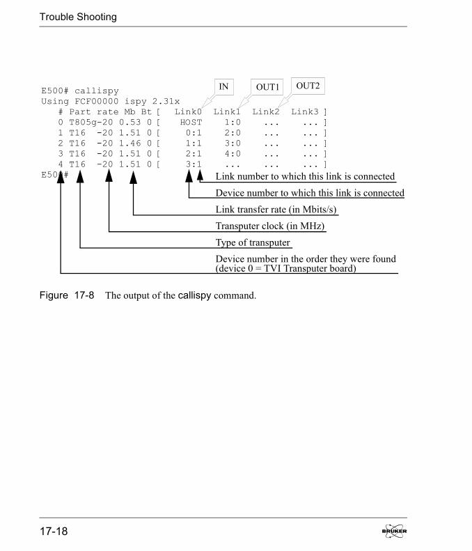
Trouble Shooting
Figure 17-8 The output of the callispy command.
E500#
E500# callispyUsing FCF00000 ispy 2.31x # Part rate Mb Bt [ Link0 Link1 Link2 Link3 ] 0 T805g-20 0.53 0 [ HOST 1:0 ... ... ] 1 T16 -20 1.51 0 [ 0:1 2:0 ... ... ] 2 T16 -20 1.46 0 [ 1:1 3:0 ... ... ] 3 T16 -20 1.51 0 [ 2:1 4:0 ... ... ] 4 T16 -20 1.51 0 [ 3:1 ... ... ... ]
Link number to which this link is connectedDevice number to which this link is connectedLink transfer rate (in Mbits/s)Transputer clock (in MHz)Type of transputerDevice number in the order they were found(device 0 = TVI Transputer board)
IN OUT1 OUT2
17-18
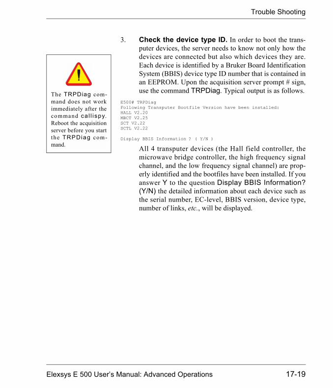
Trouble Shooting
3. Check the device type ID. In order to boot the trans-puter devices, the server needs to know not only how thedevices are connected but also which devices they are.Each device is identified by a Bruker Board IdentificationSystem (BBIS) device type ID number that is contained inan EEPROM. Upon the acquisition server prompt # sign,use the command TRPDiag. Typical output is as follows.
E500# TRPDiagFollowing Transputer Bootfile Version have been installed:HALL V2.20MBCT V2.25SCT V2.22SCTL V2.22
Display BBIS Information ? ( Y/N )
All 4 transputer devices (the Hall field controller, themicrowave bridge controller, the high frequency signalchannel, and the low frequency signal channel) are prop-erly identified and the bootfiles have been installed. If youanswer Y to the question Display BBIS Information?(Y/N) the detailed information about each device such asthe serial number, EC-level, BBIS version, device type,number of links, etc., will be displayed.
The TRPDiag com-mand does not workimmediately after thecommand cal l ispy.Reboot the acquisitionserver before you startthe TRPDiag com-mand.
Elexsys E 500 User�s Manual: Advanced Operations 17-19

Trouble Shooting
4. Check the transputer booting files. The serverneeds to know where to find the correct bootable files foreach device. A file called trpboot lists the device type ID,the corresponding bootable file, and the path of the file.You can check the trpboot file in a UNIX shell window.Change to the /usr/xepr/AcquisitionServer/OS9/Serv-ers/<Server name: e.g. E500, E580, etc.>/r0 directoryand then type os9view trpboot. The contents of the trp-boot file looks as follows.
eleXsys /usr/xepr/AcquisitionServer/OS9/Servers/E500/r0> os9view trpboot****************************************************************************** BOOT FILE FOR THE TRANSPUTER SYSTEM** The instructions and comments.********************************************************************************************
#DEVICE: /trp/root * name of ROOT transputer
#BOOTFILES
0 0 /xacq/Servers/TRPBTL/ident16.btl * Initial Loading File 1 0 /xacq/Servers/TRPBTL/ident32.btl * Initial Loading File 4 0 /xacq/Servers/TRPBTL/er032t_win.btl * ER032T Field Controller 5 0 /xacq/Servers/TRPBTL/mbct_win.btl * Microwave Bridge Controller 6 0 /xacq/Servers/TRPBTL/sct_win.btl * High Frequency Signal Channel 7 0 /xacq/Servers/TRPBTL/mwb_win.btl * Microwave Bridge Controller 10 0 /xacq/Servers/TRPBTL/sctl_win.btl * Low Frequency Signal Channel 11 0 /xacq/Servers/TRPBTL/ppu.btl * Pulse Programmer 12 0 /xacq/Servers/TRPBTL/tsa_win.btl * Transient recorder
#DUMMYFILES
0 0 /xacq/Servers/TRPBTL/dummy16.btl * Dummy Loading File 1 0 /xacq/Servers/TRPBTL/dummy32.btl * Dummy Loading File
17-20
Trouble Shooting
5. Check for transputer device booting errors. If thebootable file for the device type ID is missing, filename/extension is incorrect, or the file is in a wrong direc-tory the transputer device will abort the booting proce-dure. The error messages are stored in the file calledtrpstart.out in the same directory as the trpboot file. Youcan view this file by typing os9view trpstart.out.
Elexsys E 500 User�s Manual: Advanced Operations 17-21

Notes
17-22
Index
Aaccessories 12-1 to 12-44
accumulations per point (See rapid scan.)ACPU (See acquisition server.)acquisition server
address 17-12booting process 17-4, 17-5connections 17-2, 17-3diagnostics 17-1 to 17-21installation 15-8, 16-14network interface
Linux 16-3SGI 15-2
trouble shooting 17-6 to 17-21
ADF 6-1 to 6-19
accumulations 6-1AI 13-19, 13-20AUX 13-18, 13-19connectors 13-18 to 13-20digitizing rate 6-1externally controlled field sweep 14-33,
14-34indicators 13-17, 13-18transient signal capture 14-32
AFC trap 2-15, 3-4
automatic post-processing 9-1 to 9-14
$nr-Start 9-5activating 9-2 to 9-7Auto #2 9-8 to 9-10
Auto #3 9-8, 9-11, 9-12calling sub-routines 9-8, 9-9chain routine 9-8 to 9-14checking 9-6, 9-12, 9-13command 9-4defining 9-3, 9-10, 9-12enabling 9-3, 9-10, 9-12FFT-type 9-4handle number 9-5multiple routines (See automatic
post-processing, chain routine.)post-save 9-4raw-save 9-3save-file 9-4save-path 9-4save-title 9-4storing 9-4
Bbridge (See microwave bridge.)BVT 1000 (See variable temperature.)BVT 2000 (See variable temperature.)BVT 3000 (See variable temperature.)
Ccalibration (See individual units or acces-
sories.)cavity
Elexsys E 500 User�s Manual: Advanced Operations

Index
calibration (See signal channel, calibra-tion.)
configurationLinux workstation 16-7 to 16-12magnetic field 4-1 to 4-4microwave band 4-5microwave frequency counter 4-6SGI workstation 15-4 to 15-6signal channel 4-10, 4-11signal paths (See wiring & connectors.)spectrometer 4-1 to 4-11temperature controller 4-8transient recorder 4-9
connector (See wiring & connectors.)console module arrangement 13-1
Ddelay time (See rapid scan, field sweep,
delay time.)digitizer (See ADF.)DIP switches (See microwave bridge con-
troller.)DNS 15-2, 15-3, 16-3 to 16-5, 17-15
double modulation (See setup.)DPPH 2-2, 2-3, 2-5, 2-9, 2-12, 2-13, 2-17,
2-18, 2-20, 7-12, 12-28, 12-29, 14-8
EE 033M (See FF-Lock.)
E 035M (See teslameter.)ER 032T (See Hall field controller.)ER 218PG1 (See goniometer.)ER 4111 VT (See variable temperature.)ER 4112 HV (See variable temperature)ER 4121 VT (See variable temperature.)ER 4131 VT (See variable temperature.)ESR OUT 13-2, 13-11, 13-19
Ethernetconfiguration 17-13, 17-14connections 17-3
experiment setup 14-1 to 14-34
EXT. MOD OUT 13-2, 14-25
EXT. MOD. IN 13-3, 13-13, 14-19, 14-25
EXT. SIG. IN 13-2, 13-11, 14-24, 14-25
EXT. TRG 13-2, 13-3, 13-11
external modulation (See setup.)external trigger (See setup.)
Ffast digitizer (See ADF.)FF-Lock 12-17 to 12-30
button 12-21, 12-22cable 11-2configuration 4-2connecting
ER 032 T cable 12-18GSI board 12-20IEC 625 12-20
I-2

Index
MAG IN 12-19MAG. OUT 12-18MOD OUT 12-20Modulation/Sweep 12-20power supply cable 12-20probe head 12-20SIG IN 12-20signal cable 12-20SWA 12-19
error 12-24, 12-25, 12-30external standard 12-17, 12-26, 12-28IEEE 488
DIP switches 12-21installation 12-18 to 12-21lock-in mode 12-21 to 12-23lost lock 12-24marker 12-27marker mode 12-26 to 12-30maximum sweep width 12-25offset calibration 4-2, 12-28, 12-29operating range 12-17, 12-24, 12-25probe 12-17, 12-18, 12-20, 12-26, 12-28troubleshooting 12-24, 12-25
field controller(See Hall field controller.)
field frequency lock (See FF-Lock.)field offset (See Hall field controller, field
offset.)Fremy�s salt 5-2
frequency counter 12-2 to 12-5
Bruker frequency counter 12-4cable 11-2configuration 4-6EIP 12-4, 12-5
HP 12-4, 12-5MBC 12-2, 12-3
calibration 12-3configuration 12-2
frequency drift 12-17
FTP 15-6, 15-29, 16-42
Ggaussmeter (See teslameter.)g-factor
display 5-10DPPH 2-2measurements 5-9, 5-10perylene 5-2pitch sample 2-3precision 5-10
goniometer 12-39 to 12-44
2D experiment 12-43, 12-44cables 12-39configuring 12-40 to 12-44defining experiments 12-40defining zero 12-42initializing 12-42installation 12-39, 12-40set angle 12-42
GSI 12-20, 12-32, 17-2, 17-5, 17-6
HHall field controller
Elexsys E 500 User�s Manual: Advanced Operations I-3
Index
configuration 4-2connectors 13-15field offset 5-1 to 5-9
calibration 4-2measurement 5-2 to 5-7measurement tips 5-8, 5-9standards 5-1
indicators 13-5, 13-15
HCPU (See Hall field controller)help
accessing 10-4file format 10-1, 10-2file locations 10-3filenames 10-3implementing 10-1 to 10-4keyword 10-4selection box 10-4
high pass filter 2-15, 3-4, 14-23, 14-28
hysteresis 5-8, 6-13
IIEC 625 12-20, 12-32
IEEE 488address
FF-Lock 4-2, 12-21frequency counter 4-6ITC 5 12-10temperature controller 4-8teslameter 4-3transient recorder 4-9
connectionFF-Lock (See FF-Lock, connecting.)frequency counter 12-5
indicators & connectors 13-2 to 13-7
input mode (See rapid scan, time sweep orrapid scan, field sweep.)
IRIX (See SGI workstation.)ITC 503 (See variable temperature)
LLinux workstation 16-1 to 16-42
configuration 16-7 to 16-12general information 16-1, 16-2network setting 16-3 to 16-6
LOCK OUT 13-2, 13-11
Mmacro 8-1 to 8-16
%ARG 8-11%DESC 8-10%NOHIS 8-10%TERM 8-10argument 8-11comments 8-15data type 8-12default value 8-12dialog box 8-13, 8-14editing 8-10 to 8-16example 8-15, 8-16executing 8-6flag 8-12hotkey 8-8
I-4
Index
naming 8-3recording 8-2 to 8-6user button 8-7 to 8-9
microwave bridgechanging 11-1 to 11-8cooling water
connecting 11-5disconnecting 11-1
installing 11-4 to 11-8iris motor controller cable 11-2power supply cable
connecting 11-5disconnecting 11-2
remote control cable 11-2connecting 11-5
removing 11-1 to 11-3signal cable
connecting 11-6disconnecting 11-2
microwave bridge controllerDIP switches 11-7, 11-8frequency offset calibration 4-6
MOD REF 13-2, 13-10
modulation amplifier 13-13, 13-14
monitoring panelselecting position 15-11, 16-19
Nnetworking
Linux workstation 16-3 to 16-6, 16-40 to16-42
SGI workstation 15-2, 15-3, 15-27 to15-29
NFS 15-2, 15-4, 15-5, 15-29, 16-3, 16-7,16-12, 16-42
nonlinear 2D experiment 7-9 to 7-12
user defined scan 7-10
nonlinear acquisition 7-1 to 7-12
nonlinear field sweep 7-2 to 7-8
user defined sweep 7-5
PPADS (See Fremy�s salt.)perylene 5-2
PID 12-16
pitch samples 2-3
printerinstalling
Linux workstation 16-28 to 16-34SGI workstation 15-20 to 15-23
setupLinux workstation 16-21, 16-22SGI workstation 15-13, 15-14
printingLinux workstation 16-35 to 16-37printer setup (See printer.)SGI workstation 15-23, 15-24trouble shooting
Linux workstation 16-38, 16-39SGI workstation 15-25, 15-26
Elexsys E 500 User�s Manual: Advanced Operations I-5
Index
Qquadrature detection (See setup.)
Rramp-down time (See rapid scan, field
sweep.)ramp-up time (See rapid scan, field
sweep.)rapid scan
2D experiment 6-16, 6-17configuration 4-4field sweep 6-7 to 6-15
accumulations per point 6-14, 6-15calibration 6-18, 6-19center field offset 6-11, 6-13, 6-19configuration 6-8defining experiment 6-9field parameters 6-11input mode 6-12, 6-13rapid scan coils 6-8repetition frequency 6-15RSC trigger mode 6-12, 6-13sweep delay time 6-12, 6-15sweep ramp-down time 6-12, 6-15sweep ramp-up time 6-12, 6-14sweep width 6-11, 6-13
time sweep 6-1 to 6-6accumulations per point 6-5defining experiment 6-2external point 6-6external sweep 6-6input mode 6-6internal point 6-6internal sweep 6-5sweep time 6-5
trigger mode 6-5trigger slope 6-6
rapid scan coils (See rapid scan, fieldsweep.)
remote operation (See networking.)repetition frequency (See rapid scan.)RESONATOR 1 13-3, 13-14, 14-2
RESONATOR 2 13-3, 13-14, 14-2
RS 232Bruker frequency counter 12-4VT system 12-6
RS IN 13-3, 13-14
RS OUT 200 G 13-3, 13-14
RS OUT 50 G 13-3, 13-14
RSCcalibration (See rapid scan, field sweep.)connectors 13-21 to 13-23indicators 13-21trigger 13-21, 13-22
(See also rapid scan, field sweep and set-up, external trigger.)
Ssafety
chemical i-iv to i-vielectrical i-ivmicrowave i-vi
SCT (See signal channel)SCT-PS
I-6

Index
connectors 13-2, 13-8indicators 13-9
server name 15-12, 16-20
setupdouble modulation 14-24 to 14-29external field modulation 14-19, 14-20external trigger
ADF 14-15, 14-16RSC 14-17, 14-18SCT 14-13, 14-14
externally controlled field sweep 14-33,14-34
field sweep with ADF 14-3field sweep with SCT 14-2other modulation 14-21 to 14-23quadrature detection 14-5 to 14-12
using ADF 14-30, 14-31rapid field scan with ADF 14-4time sweep with ADF 14-3time sweep with SCT 14-2transient quadrature capture 14-32
SGI workstation 15-1 to 15-29
configuration 15-4 to 15-6general information 15-1network setting 15-2, 15-3
SIG. IN 13-2, 13-8, 13-11, 14-24
signal channelcalibration 2-1 to 2-27
cryostat removal before calibration 2-9DPPH sample positioning 2-18dual cavity 2-14file 2-13harmonics 2-13modulation amplitude 2-5, 2-6
modulation amplitude limit 2-23 to 2-25modulation frequency 2-12, 2-26modulation phase 2-7parameters 2-10 to 2-18practice 2-9 to 2-27resonator
1st 2-142nd 2-14EN 801 2-18ER 4105DR 2-14ER 4119HS 2-25ER 4122SHQ 2-13ER 4122SHQE 2-25
theory 2-4 to 2-8tuning box 2-6tuning capacitor (See tuning capacitors.)
configuration (See configuration, signalchannel.)
connectors 13-2, 13-3, 13-10 to 13-12indicators 13-4, 13-12LEDs (See indicators.)power supply (See SCT-PS.)
signal to noise measurement 3-2 to 3-28
calculation 3-22 to 3-26formula 3-2linear drift 3-21noise 3-13 to 3-22parameters 3-3, 3-28signal 3-6 to 3-12standard cavity 3-28weak pitch 3-4
slow device busER 4111 VT 12-6goniometer 12-39
standard samples 2-2, 2-3
Elexsys E 500 User�s Manual: Advanced Operations I-7

Index
strong pitch (See pitch samples.)SWADV 13-2, 13-8, 13-15, 14-33
system performance tests 3-1 to 3-28
Ttelnet 15-28, 16-41, 17-17
TEMP 13-4, 13-9
temperature controller (See variable tem-perature.)
teslameter 12-31 to 12-38
activating 12-33, 12-34configuration 4-3installation 12-31 to 12-33modulation 12-35offset calibration 4-3, 12-37, 12-38optional control 12-36resolution 12-35search direction 12-36search limit 12-36standard control 12-35troubleshooting 12-38
transient recorderconfiguration 4-9
transient signal capture (See setup.)transputer
booting 17-5connectors 13-6 to 13-7diagnostics 17-16 to 17-21
trigger mode (See rapid scan, time sweepor rapid scan, field sweep.)
trigger slope (See rapid scan, time sweep.)TTL 13-2, 13-3, 13-8, 13-11, 13-15, 13-18,
13-21, 13-22, 14-13, 14-15, 14-17,14-21, 14-25, 14-31, 14-32
tuningcapacitors 2-5 to 2-7, 2-12, 2-22, 4-11
typographical conventions 1-4
Vvariable temperature 12-6 to 12-16
BVT 1000 (See ER 4111 VT.)BVT 2000 (See ER 4121 VT.)BVT 3000 (See ER 4131 VT.)configuring 4-8, 12-7, 12-11connecting 12-6, 12-10defining experiments 12-9, 12-12ER 4111 VT 12-6 to 12-9ER 4112 HV 12-10 to 12-16
gas flow 12-15heater 12-15ITC Control 12-14 to 12-16PID 12-14, 12-16set temperature 12-12setting up 12-10 to 12-12temperature folder 12-12, 12-13tolerance 12-13
ER 4121 VT 12-6 to 12-9ER 4131 VT 12-6 to 12-9ITC 5 (See ER 4112 HV.)offset 4-8
VT or VTU (See variable temperature)
I-8
Index
Wwaveguide
extension 11-4
weak pitch (See pitch samples.)wiring & connectors 13-1 to 13-23
XXepr
abortingLinux workstation 16-26, 16-27SGI workstation 15-18, 15-19
files to backupLinux workstation 16-13SGI workstation 15-7
icon 15-9, 16-17initial setup
Linux workstation 16-15 to 16-23SGI workstation 15-9 to 15-15
reinstallingLinux workstation 16-13, 16-14SGI workstation 15-7, 15-8
startingLinux workstation 16-24, 16-25SGI workstation 15-16, 15-17
upgradingLinux workstation 16-13, 16-14SGI workstation 15-7, 15-8
Xepr printer (See printer.)
Elexsys E 500 User�s Manual: Advanced Operations I-9

Notes
I-10