Embed Size (px)
Citation preview
7/29/2019 Epnews 2012 Spring
http://slidepdf.com/reader/full/epnews-2012-spring 1/24
CONTENTS
Development of Novel Methods
for CO2 Flood Monitoring...........1
Commentary ...................................
An Innovative Approach to
Creating Stable CO2 Foam:Nanoparticles .................................8
Improving Mobility Control inCO2 Enhanced Recovery Using
SPI Gels........................................... 10
Assessing Near Miscible CO2Applications to Improve Oil
Recovery (IOR) in Arbuckle
Reservoirs ......................................13
CO2 EOR in Residual Oil ZonesShowing Expansive Potential... 16
Spotlight........................................0
CONTACTS
Roy Long
Technology Manager—
Ultra-Deepwater, Strategic
Center for Natural Gas & Oil
81-494-50
Albert Yost
Technology Manager—
Exploration & Production,Strategic Center for
Natural Gas & Oil
304-85-4479
Oil & Natural Gas Program NewsletterSpring 01
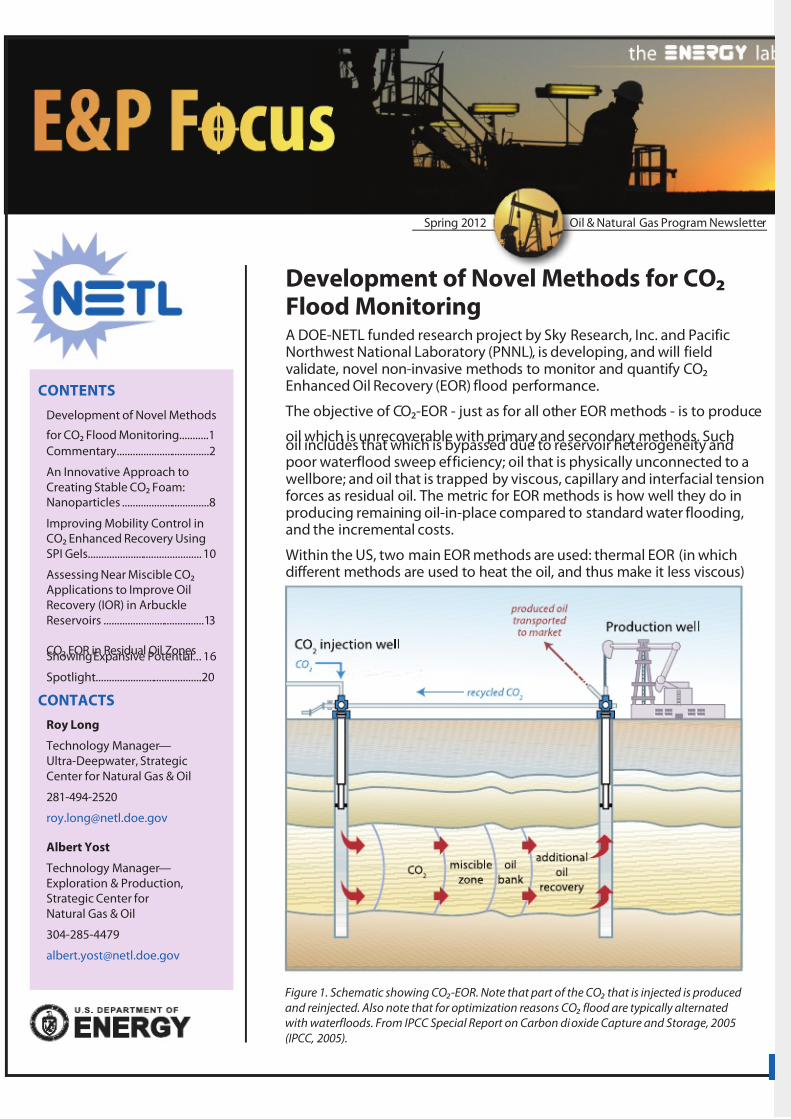
Development of Novel Methods for CO2Flood MonitoringA DOE-NETL funded research project by Sky Research, Inc. and PacificNorthwest National Laboratory (PNNL), is developing, and will fieldvalidate, novel non-invasive methods to monitor and quantify CO2Enhanced Oil Recovery (EOR) flood performance.
The objective of CO2-EOR - just as for all other EOR methods - is to produce
oil which is unrecoverable with primary and secondary methods. Suchoil includes that which is bypassed due to reservoir heterogeneity andpoor waterflood sweep efficiency; oil that is physically unconnected to awellbore; and oil that is trapped by viscous, capillary and interfacial tensionforces as residual oil. The metric for EOR methods is how well they do inproducing remaining oil-in-place compared to standard water flooding,and the incremental costs.
Within the US, two main EOR methods are used: thermal EOR (in whichdifferent methods are used to heat the oil, and thus make it less viscous)
Figure 1. Schematic showing CO2-EOR. Note that part of the CO2 that is injected is produced
and reinjected. Also note that for optimization reasons CO2 flood are typically alternated
with waterfloods. From IPCC Special Report on Carbon dioxide Capture and Storage, 005
(IPCC, 005).

7/29/2019 Epnews 2012 Spring
http://slidepdf.com/reader/full/epnews-2012-spring 2/24
This newsletter is available
online at http://www.netl.
doe.gov/E&P Focus
NATIONAL ENERGYTECHNOLOGY LABORATORY
1450 Queen Avenue SWAlbany, OR 9731
541-967-589
175 University Avenue SouthSuite 01Fairbanks, AK 99709
907-45-559
3610 Collins Ferry Road
P.O. Box 880Morgantown, WV 6507-0880
304-85-4764
66 Cochrans Mill Road
P.O. Box 10940Pittsburgh, PA 1536-0940
41-386-4687
13131 Dairy Ashford, Suite 5
Sugar Land, TX 7747881-494-516
Visit the NETL website at:
www.netl.doe.gov
Customer Service:
1-800-553-7681
E&P Focus is published by theNational Energy Technology
Laboratory to promote theexchange of information among
those involved in natural gas
and oil operations, research,and development.
CommentaryFirst used in Scurry County, Texas, CO2 injection inenhanced oil recovery operations (CO2 EOR) has beensuccessfully employed throughout the Permian Basinin West Texas and eastern New Mexico. It is now inuse, or to be used, to a limited extent in Alabama,Kansas, Mississippi, Wyoming, Oklahoma, Colorado,Utah, Montana, Alaska, and Pennsylvania (U.S.Department of Energy, Enhanced Oil Recovery/CO2Injection, Dec. 011, http://fossil.energy.gov/programs/oilgas/eor/). In addition to enhancing oil production,
CO2 EOR has the benefit of sequestering CO2 in oil producingformations and is seen as a critical component of future greenhousegas management programs. This facet of CO2 EOR produces valuablesynergies with the carbon capture, utilization and storage researchprogram within the Department of Energy’s Office of Fossil Energy (FE).
Until recently, most of the CO2 used for EOR has come from naturally-occurring sources – underground reservoirs. But new technologiesare being developed to capture CO2 from industrial processes suchas power generation, natural gas processing, and the productionof fertilizer, ethanol, and hydrogen in locations where naturally-occurring sources are not available. One demonstration at the DakotaGasification Company’s plant in Beulah, North Dakota is producingCO2 and delivering it by a 04-mile pipeline to the Weyburn oil field inSaskatchewan, Canada. Encana, the field’s operator, is injecting the CO2to extend the f ield’s productive life, hoping to add another 5 yearsand as much as 130 million barrels of oil that might otherwise havebeen abandoned. As more anthropogenic CO2 becomes available, it isexpected to fuel significant expansion of CO2 EOR operations.
CO2 EOR technology is evolving rapidly to a “next generation”phase, partly in anticipation of the arrival of significant amounts of anthropogenic CO2. The Department’s Office of Fossil Energy (FE)through the National Energy Technology Laboratory is actively engagedin supporting the development of next generation technologies.Our R&D program is moving into new areas, researching noveltechniques that could significantly improve the technical and economicperformance, and expand the applicability of CO2 injection to a broadergroup of reservoirs including those in basins much closer to the majorsources of man-made CO2. Next generation CO2-EOR has the potentialto produce as much as 60 billion barrels of economically recoverable
oil, using new techniques including injection of much larger volumesof CO2, innovative flood design to deliver CO2 to un-swept areas of areservoir, extending the miscibility pressure, and improving mobilitycontrol of the injected CO2.
In September 010 DOE competitively selected seven next generationCO2 EOR research projects. One project is investigating the potentialfor oil production by CO2 injection into the residual oil zone: ”NextGeneration” CO2-EOR Technologies To Optimize The Residual Oil ZoneCO2 Flood At The Goldsmith Landreth Unit, Ector County, Texas (U. Texas

7/29/2019 Epnews 2012 Spring
http://slidepdf.com/reader/full/epnews-2012-spring 3/24
“
”– Permian Basin). Four projects are developing techniques for mobilitycontrol of the injected CO2. Novel foams and gels have the potentialto prevent the highly-mobile CO2 from channeling through high-permeability areas of a reservoir, leaving un-swept, unproductive areasof the reservoir. These projects are:
• Improved Mobility Control in CO2 Enhanced Oil Recovery using SPIGels (Impact Technologies, LLC)
•
Engineered Nanoparticle-Stabilized CO2 Foams to ImproveVolumetric Sweep of CO2 EOR Processes (U. Texas - Austin)
• Novel CO2 Foam Concepts and Injection Schemes for ImprovingCO2 Sweep Efficiency in Sandstone and Carbonate HydrocarbonFormations (U. Texas - Austin)
• Nanoparticle-Stabilized CO2 Foam for CO2-EOR Application (NewMexico Institute of Mining and Technology)
Two projects are developing simulation and modeling tools for CO2 EOR:
• Real Time Semi-Autonomous Geophysical Data Acquisition andProcessing System to Monitor Flood Performance (Sky Research,Inc.),
• CO2-EOR and Sequestration Planning Software (NITEC LLC).
These 010 projects joined six ongoing R&D activities in CO2 EORpreviously funded by the Office of Fossil Energy.
Future CO2 EOR technology development will address five opportunitiesfor improving the performance of current, state-of-art CO2 EOR,specifically:
• Increasing the volume of CO2 injected,
• Capturing more of the remaining mobile and immobile oil,
• Improving sweep efficiency and mobility control (reservoir
conformance),• Improving the technology for reservoir surveillance, and
• Lowering the threshold minimum miscibility pressure (MMP).
The research and development in CO2 EOR underway within NETL’sStrategic Center for Natural Gas and Oil (SCNGO) discussed above, andthat to be undertaken in the future, will occur in concert with synergisticefforts to reduce CO2 emissions in Carbon Capture, Utilization andStorage program.
Opportunities to beneficially use captured carbonare, in a sense, “boundless”—especially for the
incremental recovery of domestic crude oil.

7/29/2019 Epnews 2012 Spring
http://slidepdf.com/reader/full/epnews-2012-spring 4/24
4
Through NETL, a technology portfolio of safe, cost-effective, commercial-scale CO2 capture and storage technologies is being developed thatwill be available for commercial deployment beginning in 00. TheDepartment’s primary capture and storage research and development(R&D) objectives are: (1) lowering the cost and energy penalty associatedwith CO2 capture from large stationary sources by more than 50 percent,
resulting in less than $5/Tonne CO2 captured; and () improving theunderstanding of factors affecting CO2 storage permanence, capacity,and safety in geologic formations and terrestrial ecosystems. Once theseobjectives are met, new and existing power plants and fuel processingfacilities around the world have the potential to be retrofitted with CO2capture technologies.
Opportunities to beneficially use captured carbon are, in a sense,“boundless” – especially for the incremental recovery of domestic crudeoil. The Department’s commitment to advancing CO2 EOR technology,while mitigating greenhouse gas emissions, is real and demonstrable.I invite each of you to visit NETL’s website for information and to stayapprised of further developments.
We hope you enjoy this issue of E&P Focus and as always, we welcomeyour comments.
John R. DudaDirector, NETL Strategic Center for Natural Gas and Oil

7/29/2019 Epnews 2012 Spring
http://slidepdf.com/reader/full/epnews-2012-spring 5/24
and gas injection, in which CO2 is the dominant gas used. CO2-EOR is oftenused as part of a Water Alternating Gas (WAG) production approach.
Depending on reservoir conditions (pressure, temperature and oilcomposition) CO2 EOR floods can be either miscible - in which the injectedCO2 and the hydrocarbons form a single phase fluid with favorable flowproperties, or immiscible in which the gas sweeps the oil but does notmix with it to form a single phase f luid. The majority of CO2 EOR floods aremiscible.
Significant volumes of conventional oil remain in known US oil reservoirswhich could be produced economically by CO2 EOR. Based on data fromNETL and industry, an estimated 1,673 fields and reservoirs, collectivelyaccounting for 146 billion barrels of original oil in place, are candidatesfor CO2 flooding. CO2 flooding has been underway for several decades,initially in the Permian basin of West Texas and New Mexico, but currentlybeing pursued at multiple sites across the US. CO2 EOR currently providesfor about 80,000 barrels of oil per day, equal to 6 % of US crude oilproduction.
While the large majority (roughly 80 %) of the CO2 for CO2 EOR has come
from natural CO2 fields an increasing percentage of CO2 comes fromanthropogenic sources (coal gasification, gas processing and fertilizerplants). It is expected that limits on natural sources of CO2 , increaseddemand for CO2 for EOR as well as a decrease in cost of anthropogenicCO2 will result in a substantial change in the amount of anthropogenicCO2 which will be used in EOR. While a substantial percentage of CO2which is being injected in reservoirs is currently being produced with thehydrocarbons and reinjected in the subsurface (and CO2 remaining in thereservoir at the end of the EOR phase could, at least partially, be produced)the potential of using CO2-EOR as part of a Carbon Capture, Utilizationand Sequestration strategy has been broadly recognized both by theDepartment of Energy, industry and academia.
Cost of CO2 EORCO2 EOR requires a substantial upfront investment in infrastructure forproducing, compressing, transporting and injecting CO2. It also requiresa substantial investment in CO2. In general, somewhere between 4-8thousand cubic feet of CO2 (0.-0.44 metric tons of CO2) will need to beinjected per barrel of oil produced. While some of this CO2 is recycledfrom production wells, a substantial amount will need to be purchased(especially in the initial years of EOR). While exact costs will varysubstantially per site (and are rarely published explicitly), an approximatecost of $0/metric ton CO2 at the wellhead for fresh, naturally sourcedCO2 and a cost about $4/metric ton for recycled CO2, seem to representindustry costs. Overall injection of CO2 will thus add substantially ($5-$15/barrel) to the cost per barrel of oil recovered.
While CO2 EOR is, thus, not free, the current price of oil and the largenumber of candidate sites, as well as all the combination of economicbenefits, national security benefits and potential for sequestration allcontribute to a substantial enthusiasm for scaling up the applicationand use of CO2 EOR. However, it is recognized that this will require thedevelopment of several novel EOR technologies.
Next Generation CO2 EOR Technologies
One of the recognized challenges by the Department of Energy andindustry is the need for a suite of next generation EOR technologies
7/29/2019 Epnews 2012 Spring
http://slidepdf.com/reader/full/epnews-2012-spring 6/24
6
which can substantially increase (by an order of magnitude or more) thenumber of fields at which EOR would be deployed as well as the amountof injected CO2 and the percentage of anthropogenic CO2. Details onthe kind of technologies and associated objectives can be found in theNETL publication Improving Domestic Energy Security and Lowering CO2Emissions with “Next Generation” CO2-Enhanced Oil Recovery (CO2-EOR)( DOE/NETL-011/1504) available from the NETL website. The technology
being developed by Sky Research and PNNL is part of the suite of such nextgeneration technologies. Specifically, the objective of the Sky and PNNLdeveloped technology is to provide a novel and enhanced monitoringcapability for CO2 EOR floods.
CO2 EOR Flood Characterization
Information on CO2 EOR behavior is currently primarily obtained by theinterpretation of injection and production data coupled with sparse in-well measurements and forward reservoir modeling. While this providesmacroscopic insights into flood behavior it only allows for rudimentaryflood optimization due to the lack of volumetric spatiotemporalinformation on flood behavior. Such knowledge would ideally includeboth displacement and phase changes as well as geochemical reactions
associated with the flood. Access to this information would allow industryto refine and optimize injection strategies, and would result in increasedoil production and/or reduced operating costs. This in turn would allowCO2 EOR to be applied to sites where currently it may not be economical toapply, resulting in increased domestic oil production.
Project Approach: Development of Time-Lapse Geophysics forCO2 EOR flood monitoring
Geophysical methods are a standard tool for obtaining information onvolumetric distributions of subsurface physical properties of rocks andfluids. If one collects geophysical datasets with the same parameters atthe same position over time, changes in the geophysical data between
surveys can be interpreted in terms of dynamic subsurface processes. Thisapproach is known as time lapse or 4-D geophysics, and it has been widelydemonstrated to provide actionable information on processes of interest.Within the oil industry, the predominant time lapse geophysical methodused is time lapse seismic. However, one of the major changes in physicalproperties which occur in WAG is a change in electrical conductivity of thereservoir. This electrical conductivity will increase when brine is injected,and decrease when CO2 is injected. Measurements of electrical propertiesfrom measurements done during WAG show that such changes can be of one order of magnitude or more. This motivates the research of the Sky/PNNL project: develop a semi autonomous geophysical data acquisitionsystem to provide near real time information to stakeholders on f loodbehavior (Figure )
In this system, a combination of surface and borehole time lapse timedomain electromagnetic and electrical resistivity measurements willbe inverted to obtain a spatial and temporal distribution of changes inreservoir electrical properties. By combining these changes with a reservoirmodel through a coupled inversion this can provide actionable informationto field operators on flood behavior. This information could be used totune and optimize the flood.
Project Progress
This project started in February 011 and is currently in its second year.

7/29/2019 Epnews 2012 Spring
http://slidepdf.com/reader/full/epnews-2012-spring 7/24
Figure . System being developed by Sky Research and PNNL
In the first year a coupling between reservoir modeling of CO2 EOR andelectromagnetic forward modeling of the expected associated signatures,as well as literature studies, validated the overall concept. Also, an industrypartner was found with which the project team is working towards a fielddemonstration in year three of the project. Currently (in year ) the coupledinversion framework is being developed, and the data acquisition hardwareis being completed. This will lead to a system field demonstration which
aims to demonstrate and validate this concept, and develop a new toolwhich can be used by the industry to obtain information on CO2 EORfloods.
For additional information about this project, contact Roelof Versteeg atSky Research ([email protected] or 603-643-516), AlainBonneville at PNNL ([email protected] 509-371-763) or ChandraNautiyal at NETL ([email protected] or 81-494-488).

7/29/2019 Epnews 2012 Spring
http://slidepdf.com/reader/full/epnews-2012-spring 8/24
8
An Innovative Approach to Creating StableCO2 Foam: NanoparticlesA persistent challenge for operators of CO2 enhanced oil recovery projectsis the poor sweep efficiency that can result from the difference in mobilitybetween the reservoir oil and water and the displacing carbon dioxide
gas injectant. One approach that has been put forward for addressingthis problem is to increase the viscosity of the CO2 by adding surfactantsto create CO2 foam. However, maintaining the stability of CO2 foams canbe problematic at downhole conditions. NETL has teamed with the NewMexico Institute of Mining and Technology’s Petroleum Recovery ResearchCenter in Socorro, NM to develop and evaluate, through coreflood tests atreservoir conditions, a nanoparticle-stabilized CO2 foam system that canimprove CO2 sweep efficiency and minimize nanoparticle retention in thereservoir.
Background
Research results have demonstrated that surfactant-induced CO2 foam is aneffective method for mobility control in CO2 foam flooding. NETL recently
published a literature review titled “Mobility and Conformance Control forCarbon Dioxide Enhanced Oil Recovery (CO2-EOR) via Thickeners, Foams,and Gels – A Detailed Literature Review of 40 Years of Research (DOE/NETL-01/1540) that highlights the progress of research in this area, amongothers.
However, surfactant-stabilized CO2 foams have some potential weaknesses.Because the foam is by nature ultimately unstable, its long-term stabilityduring a field application is difficult to maintain. This is especially truewhen the foam contacts the resident oil. Even though some high-cost,specialty surfactants are available, under high-temperature reservoirconditions, surfactants generally tend to degrade before they fulfilltheir long-term function. In addition, surfactant loss in a reservoir due to
adsorption onto the rock matrix results in large chemical consumption andreduces the economic viability of CO2 foam flooding.
New nano-science technologies may provide an alternative for the nextgeneration of stable CO2 foam. It is known that small solid particles canadsorb at fluid/fluid interfaces to stabilize droplets in emulsions andbubbles in foams. These solid-stabilized dispersions may remain stablefor years. The high adhesion energy for the particles enables adsorptionand is essentially irreversible; thus solid nanoparticles strongly andpreferentially adsorb to either the water or gas phase at the water/CO2interface and create a protective barrier around each dispersed bubble of gas (if the nanoparticle is hydrophilic) or drop of water (if the nanoparticleis hydrophobic) to produce highly stable and durable foam. Nanoparticlesare solids that can withstand harsh environments and high temperatures.If they can be successfully demonstrated to stabilize CO2 foams, they coulddrastically reduce the costs of improving mobility in a CO2 EOR operation.
Research Accomplishments to Date
The research team has generated stable CO2 foams at reservoir conditionsfor a nanoparticle concentration in the 4,000 to 6,000 ppm range.Nanosilica powder, with an average particle diameter of 100-150 nm, wasused as the stabilization agent (Figure 1). The effects of different factorssuch as particle concentration, brine salinity, pressure, and temperature onCO2 foam generation have been investigated. Adding a small amount (30-50 ppm) of surfactant to a nanoparticle solution significantly improved CO2

7/29/2019 Epnews 2012 Spring
http://slidepdf.com/reader/full/epnews-2012-spring 9/24
foam generation and foam stability.
For the first time, CO2 foam was generated as a mixture of supercritical CO2and nanosilica and was flowed through sandstone and limestone cores. The apparent viscosity of the mixture with dispersed nanoparticles was 1.5to 6.1 times higher than that without nanoparticles.
Current Status
The research team is continuing to investigate CO2 foam generation atdynamic conditions with nanosilica particle-stabilized CO2 foam. Foamtexture is being identified visually via a sapphire observation cell (Figure ).Particle concentration, phase ratio between CO2 and nanoparticle solution,and flow rate effects on CO2 foam generation and foam mobility in theporous media are being investigated. Oil-free coreflooding experimentsto investigate nanoparticle transportation in sandstone, limestone, anddolomite are also being performed, and particle retention in the coresamples is being estimated. Further research will investigate the impact of nanoparticles as foam stabilizers on residual oil recovery under reservoirconditions.
For additional information on this project, contact Sinisha (Jay) Jikich at
NETL ([email protected] or 304-85-430) or Ning Liu at NewMexico Tech ([email protected] or 575-835-5739).
Figure 1. This image is of nanosilica
particles with a diameter of 105
nanometers (nm). A nanometer is 1/1000
of a micrometer, which is 1/1000 of a
millimeter. For reference, a human hair
is about 60 micrometers in diameter.
The median diameter of the nanosilica
particles used in the CO2 foam generation
experiments were abo ut 100-150 nm, or
about 1/500 the diameter of a human hair.
Figure . Images of CO2 foam generation in a sapphire cell with varied phase ratios. The
volumetric phase ratio is the volume of supercritical CO2 to the volume of nanosilica
dispersion, sometimes called CO2 fraction or CO2 quality. It can be seen that the CO2 foams
are generated successfully over a wide range of phase ratios. The CO2 foam depicted here
was micron-scaled and displays a very uniform morphology

7/29/2019 Epnews 2012 Spring
http://slidepdf.com/reader/full/epnews-2012-spring 10/24
10
Improving Mobility Control in CO2Enhanced Recovery Using SPI GelsA project being undertaken by The Letton-Hall Group, Impact Technologies LLC and Clean Tech Innovations LLC (CTI), with funding fromthe National Energy Technology Laboratory (NETL), will demonstrate the
ease of use and potential of carbon dioxide (CO2) injection/ productionprofile modifications using Silica Polymer Initiator (SPI)-CO2 gel systems. The objective is to advance SPI-CO2 Enhanced Oil Recovery (EOR) geltechnology by performing multiple small- scale, field injectivity tests usingboth ‘Huff & Puff’ and conventional pattern flood applications. A secondaryobjective of the project is to improve the SPI-CO2 gel integrity by testinga Super Absorbent Polymer (SAP) instead of the polyacrylamide (PAM)currently being used.
Issues associated with using CO2 for EOR are its low density and viscositycompared to the crude oil and brine in the reservoir. The injected CO2 hassubstantially higher mobility relative to the crude oil and brine, whichpromotes “fingering” and early breakthrough of the CO2 to the productionwells. High conformance or sweep efficiency (i.e., good contact with all
the crude oil in the reservoir) is particularly critical in costlier CO2 floodswhere the end result of poor sweep efficiency is less oil recovered withsubstantially higher costs resulting from multiple handling (production,compression, and reinjection) of the CO2.
Research has gone into developing gels for the primary CO2 phase, butnone are low cost and commercial. A unique, state-of-the-art SPI gelsystem may offer a promising solution to the conformance problemwith CO2 floods. Of particular importance to this and other CO2 injection
Figure 1. SPI gel with internal initiator
Figure . SPI gel with CO2 initiator.

7/29/2019 Epnews 2012 Spring
http://slidepdf.com/reader/full/epnews-2012-spring 11/24
projects is the use of an external initiator such as CO2. In SPI-CO2 gels, theCO2 becomes the external initiator of the SPI fluid following its placementin the reservoir (Figure 1 and ).
An SPI mix slug will be incorporated in the water cycle of a WaterAlternating Gas (WAG) injection and the CO2 slug that follows will “finger”through and permeate the more viscous aqueous SPI mixture in the flowpath, generating carbonic acid, which will immediately initiate the gelationprocess. This newly set SPI gel diverts the CO2 that follows and causes itto finger and dissolve into fresh SPI mix, leading to SPI gel formation atadditional locales. The process continues until the CO2 is fully blocked or allthe SPI mix is consumed (Figure 3).
The SPI gel can improve sweep efficiency to a greater degree thanconventional systems because it sets up in the high permeability paths thathad been travelled previously by the CO2 and is unique in that it is silicate
based and will remain a low viscosity fluid until gel initiation is triggeredby CO2. This is a clear improvement over current technology where the gelgradually sets up as a function of time, regardless of location. In addition,the final product in commercial quantities is expected to be less expensivethan competing polymer gels or other systems.
U.S. CO2 EOR production has grown by four percent/year over the last 0years to today’s level of 80,000 barrels of oil per day. The use of SPI gelsis anticipated to further improve those levels by one percent/year withina few years of a successful demonstration and up to three percent/year infuture years. SPI could add over 300 million barrels of otherwise bypassedreserves over 10 years.
Accomplishments
The team has been in contact with major CO2 flood operators to ascertaintheir needs and to inquire about performing tests in their fields. Severalindustry contacts have indicated that SPI gels have a place in the CO2market if the gels perform as expected during the project’s field test. Legalagreements are being pursued with two companies and one company hasprovided the project team with field data, fluids, and core segments for useand analysis. One major CO2 flood operator wants to get to the field rightaway, while other operating companies have expressed interest.
The CTI lab performed over 600 gel forming bench tests, half at roomtemperature (74°F) and half at 140°F. Approximately 40 additives have
Figure 3. CO2 flows through aqueous SPI in the reservoir to form carbonic acid which
initiates the gelation process.

7/29/2019 Epnews 2012 Spring
http://slidepdf.com/reader/full/epnews-2012-spring 12/24
1
been evaluated to date at various concentrations and combinations withadditional additives. Three formulations look very promising as candidatesfor further sand pack testing.
The base SPI polyacrylamide polymer was changed to a much easierto hydrolyze ultra-high molecular weight polymer. This has benefits of easier mixing in the field and better isolation of the SPI mix within highpermeability zones, a key interest of the industry.
A full CO2 capable sand pack system was developed at the CTI laboratoryin Bartlesville, Oklahoma. Operational improvements to the modified sandpack system have been completed allowing the use of supercritical CO2 at1500 psi. These improvements include:
• Safe handling and discharging of carbon dioxide,
• Accurate means to meter and deliver supercritical carbon dioxide tocore apparatus for sand pack testing, and
• Accurate means to meter and account for all gas and liquid massexiting the system, and other improvements to aid in closing a massbalance (a % mass balance closure is anticipated).
Impact Technologies is continuing to communicate with chemicalproviders and CO2 operators on a frequent basis with the goal of securingmultiple CO2 flood operators for field testing of the SPI gel. By early 01,Impact Technologies plans to begin ordering the required chemicalsnecessary to complete testing and begin treatments in selected fields.
Test plans for field activity will be developed and will include: preparationof the well and site for the field injectivity test (i.e. roads to the wellsite must be accessible); access to electricity to the site must be madeavailable, unless generation is anticipated and desired; finalization of legaldocuments (liability releases, safety training, data releases) before movingonto the site; obtaining injection well and offset well data (oil rates, waterrates, CO2 rates, pressures, profile surveys, tracer surveys) to establish a pre-
test base line; ordering and delivery of pumps, rate/ pressure recording andmetering equipment to the field site.
For additional information on this project contact William Fincham at NETL([email protected] 304-85-468) or Kenneth Oglesby atImpact Technologies ([email protected] or 918-67-8035)
7/29/2019 Epnews 2012 Spring
http://slidepdf.com/reader/full/epnews-2012-spring 13/24
Assessing Near Miscible CO2 Applicationsto Improve Oil Recovery (IOR) in ArbuckleReservoirsSince the 1910’s, several billion barrels of oil have been produced fromthe Central Kansas Uplift (CKU), primarily from carbonate reservoirs within
the Arbuckle and Lansing-Kansas City groups. The majority of Arbucklereservoirs in central Kansas were drilled prior to 1955 and constitute aseries of giant and near giant oil fields. Improved oil recovery throughCO2 flooding has the potential to increase recovery from this maturereservoir. However, due to the lack of coring, modern well logging, and welltesting in the past, Arbuckle reservoirs have not been well characterized.Current understanding of the Arbuckle is based on a conceptual modelwith limited petrophysical, drill stem test and pressure build up data. Theuncertain reservoir properties make IOR challenging in Arbuckle reservoirsas the nature of flow is affected by reservoir properties and heterogeneity.
In order to ultimately predict IOR in a future CO2 flood, an evaluationplan was designed to obtain data that pertain to the pressure, residual oil
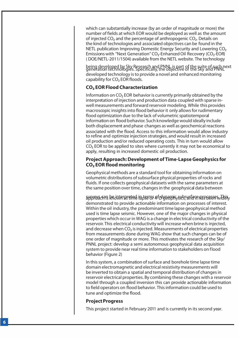
saturation, reservoir properties and the nature of the flow from well towell. The evaluation methods include single well transient pressure tests,multiple well interference tests, single well tracer tests, and inter-well tracertests (Figure 1).
All tests are designed to determine the nature of the flow paths andaverage properties in the reservoir, to assess the effect of geology onprocess performance, to calibrate a reservoir simulation model, and toidentify operational issues and concerns for future IOR applications.
The Arbuckle reservoir characterization project, with funding from NETL,is being conducted by the Tertiary Oil Recovery Project (TORP) at theUniversity of Kansas at a selected oil field producing from the Arbuckleformation. The participating consortium members include University
of Kansas Center for Research, Inc., TORP, University of Kansas, KansasGeological Survey and Carmen Schmitt, Inc., a small independent producer.
A field-based research project will be conducted at the Ogallah unit(Figure ) located at Trego County in Kansas to evaluate:
• Pressure distribution in the field using single well pressurebuild up tests. The well testing study will determine the potentialoperational pressure and flow capacity, wellbore conditions and otherpertinent information in selected wells for which this information doesnot exist. The entire well test data set developed from this program willbe collected and analyzed.
• Permeability-thickness between wells using well-to-well
interference tests. These tests will determine whether or not thereis communication between the test wells and surrounding wells andthe capacity of flow between wells. Pulse testing will be used in thisstudy. Before the start of pulse testing, all the test wells are shut-inuntil the pressures stabilize. The active well is then allowed to produceat a constant rate and the pressure response in the observationwell(s) is observed and recorded. The pressure data responding tothe production of the active well depend on the properties of rock and fluid and can be analyzed by commercial well test software todetermine permeability-thickness property between wells. Completionof this task allows for the determination of flow capacity and
Figure 1. A multi-faceted testing
program will be used to describe the flow
characteristics of the Arbuckle reservoir in Kansas.

7/29/2019 Epnews 2012 Spring
http://slidepdf.com/reader/full/epnews-2012-spring 14/24
14
communication between wells which is valuable and complimentaryto the well-to-well tracer tests to characterize the flow path betweenwells.
• Reservoir properties and continuity between wells usingwell-to-well tracer technology. Inter-well tracer tests will beperformed to gather information on flood patterns within the reservoirsuch that the uncertainty about flow paths and reservoir continuitymay be reduced. The tracer program will be designed to: 1) selectthe type of tracer, ) calculate the tracer volume, 3) select the well tobe injected and wells to be monitored, 4) determine the samplingfrequency, and 5) specify sampling and detection techniques. The
field execution plan will be coordinated with field personnel toimplement the tracer injection and sample collection from producers.Finally, the tracer in the samples will be analyzed and documentedto: 1) qualitatively derive the information about reservoir continuityand barriers and, ) model tracer transport for validation as necessary.Completion of this task will allow completion of the characterization of potential sites for future CO2 injection at near-miscible conditions.
• Residual oil saturation in the reservoir for CO2 application usingsingle well tracer technology. Single well tracer tests will be usedfor measuring residual oil saturation. The test will be designed suchthat a reacting partitioning (primary) tracer is injected and producedthrough the same well following a shut-in period of time. Duringthe shut-in, the primary tracer undergoes hydrolysis to generate a
non-partitioning secondary tracer. Once the producer brings back the fluid after the occurrence of hydrolysis, the secondary tracer willarrive at the wellbore earlier than the primary tracer in a volume lessthan the injected volume. Based on the chromatographic theory, theseparation of primary and secondary tracers can be quantitativelyrelated to the residual oil saturation. Special interpretation techniquesand design procedures will be considered to cope with tracer responsecharacteristics arising from the double porosity structure of carbonateif it exists. This task will be subcontracted to Chemical Tracers, Inc.for the test. Completion of this task allows for determination of theresidual oil saturation in the reservoir prior to CO2 injection. The data
Figure . The Arbuckle formation in
Ogallah unit at Trego County, Kansas,
has produced since the 1950s but still has
significant reserves that are recoverable
by near-miscible CO2 flooding.

7/29/2019 Epnews 2012 Spring
http://slidepdf.com/reader/full/epnews-2012-spring 15/24
will be used for economic analysis in the pattern design.
• Flooding pattern design for future CO2 injection with thesimulation study conducted at TORP, University of Kansas. Averified and updated reservoir model with all the data collectedfrom the proposed field tests will be used to design the floodingpattern. The pattern design will consider the operational issues andeconomic concerns for the CO2 injection applications. Simulationwill be conducted to evaluate the flooding pattern for optimizationof CO2 injection at near-miscible pressure. Completion of this task allows for development of an appropriate plan for f ield testing of CO2displacement processes at near-miscible conditions.
With improved reservoir characterization as a result of this proposedapproach, a first near miscible CO2 application based upon a betterdescription of the reservoir system will be field tested to prove thetechnology utilizing existing, easily accessed sources of CO2 (Figure 3).
Successful completion of the Arbuckle reservoir characterization, and thesubsequent demonstration project, will lead to additional oil recoveryfrom Arbuckle reservoirs in Kansas. The potential benefits could be
significant with an increase in the resource base for CO2 flooding and anexpanded opportunity for small producers to apply CO2 flooding.
For additional information on this project, contact Charlotte Schroederat RPSEA ([email protected] or 81-313-9555) or Jyun-Syung Tsau([email protected] or 785-864-913).
Figure 3. Proximity to sources of anthropogenic CO2 will enhance near-miscible CO2 flooding in the Arbuckle formation in
Trego County, Kansas.

7/29/2019 Epnews 2012 Spring
http://slidepdf.com/reader/full/epnews-2012-spring 16/24
16
CO2 EOR in Residual Oil Zones ShowingExpansive PotentialInterest in the potential of residual oil zones (ROZ) has risen exponentiallyover the past decade. First noted in the Permian Basin of West Texas andEastern New Mexico, ROZs there consist of previously untapped oil reserves
found below the oil/water contact in mature (very often water flooded) SanAndres formation oil fields. Original oil-in-place reserves for the PermianBasin have historically been estimated at about 100 billion barrels of oil.ROZs have the potential to increase those reserve estimates to 135 billionbarrels. Oil saturation in ROZs range from 0-40%, averaging 3%, similarto the oil saturation in mature waterflooded reservoirs (Figure 1).
At this point, the leading hypotheses for their origin are: 1) early geologicalentrapment with subsequent flushing caused by uplift, or ) transitionzones formed primarily by capillary forces within the pore system andbasin-wide tilt. The north and east side of the Delaware Basin and westside of the Central Basin Platform provide evidence of ROZs in severalstratigraphic horizons (the San Andres, Grayburg, Glorieta and Clearfork intervals).
A key to the production potential of those ROZ reserves is CO2 EOR. ThePermian Basin has a long history of CO2 EOR, which currently producesover 00,000 bopd in the region. Recent development of nine CO2 projectsin Permian Basin ROZs accounts for 10,000 bopd and production is rising.More recently, ROZ potential has been assessed in other mature productionareas in the US, with encouraging results.
NETL has funded research in CO2 EOR applications in ROZs since 009. Two important studies address the characterization of ROZs and theoptimization of technical and economic performance of these resources. The first was designed to describe and gather the data needed todetermine the distribution of ROZs in a portion of the Permian Basin, andto develop a methodology template for determining the presence anddistribution of ROZs in other areas of the Permian Basin. The University of Texas Permian Basin, Chevron Corporation, Yates Petroleum, and Legado
Figure 1. Illustration of a residual oil zone
with average oil saturation profile.

7/29/2019 Epnews 2012 Spring
http://slidepdf.com/reader/full/epnews-2012-spring 17/24
Resources participated in the project.
The project collected data such as well logs, field specific oil-watercontact data, groundwater samples and core data from specific horizonsand defined a flow path (or fairway) that might have flushed oil fromgeological entrapment. Zonal properties were established, flow channelsapproximated, and input and choke point (exit) conditions bounded.A regional hydrological model was constructed of the hydrodynamicfairway that helped develop a consistency with the observed data pointsof sulfur deposits, water salinity observations, and tilted oil/water contactsin reservoirs within the flow path. The data acquired and the modeldeveloped will provide features of the ROZs that can be tested withnew wells and cores. A final report will document the spectrum of datasuggesting origins and distribution of the residual oil zones in the PermianBasin, and a methodology for determining the presence and distribution of ROZs in other fairways within the Permian Basin area and other regions of the country will be outlined.
The overall nature and extent of the maximum oil entrapments in thecarbonate rocks rimming the north rims of the Delaware and MidlandBasins is being investigated. The same is being done for the west and east
sides of the Central Basin Platform (CBP). Particular attention is also beingplaced on the south side of the CBP as an exit path. The zonal propertiesare being established, the flow channels or fairways approximated, andinput and choke point (exit) conditions bounded. With this flow pathhypothesis, a regional hydrologic model is under construction. The datagathered will support an examination of charge and discharge points in anattempt to develop a consistency with the observed data points within theflow path. The scope of the relic entrapment indicators include residual oilpresence and saturations, water salinities and acidity, sour nature of the oiland gas, and oil-water-contact (OWC) tilts.
The research team is also investigating basin-wide sulfur deposits. Thisshould prove to be a critical data set. Elemental sulfur deposits form where
hydrocarbon-bearing fluids exit a water-drive system through fracturedsulfur-bearing (anhydrite, gypsum) strata. The moving fluids contact thesulfur-bearing seals whereby the displaced hydrocarbons are consumedby sulfate-reducing bacteria. The fact that continual hydrocarbonnourishment is present due to the flushed hydrocarbons and that thesulfates are extensive, leads to large sulfur deposits. In the Permian Basin,locations of the sulfur deposits are indicators of hydrodynamic flow pathsand, more specifically, suggest fairways of water movement and exitpathways.
The data acquired and model developed will provide features of the ROZsthat can be tested with new wells and cores. The results of this studycould be extended to a demonstration project wherein the developed
understanding can be tested through new wells and/or pilot flooding. The second ROZ project funded by NETL seeks to optimize the technicaland economical performance of a ROZ CO2 flood and transfer theknowledge to other operators. The objectives are to (1) characterize themain pay zone (MPZ) and ROZ within the ROZ pilot area; () conductlaboratory analyses and reservoir simulation to evaluate the performanceof the ROZ pilot flood; and (3) provide recommendations for an optimumfield wide expansion of the CO2 flood in the ROZ and MPZ at the GoldsmithField. The project is being conducted by The University of Texas of thePermian Basin with Legado Resources, Melzer Consulting and AdvancedResearch International.

7/29/2019 Epnews 2012 Spring
http://slidepdf.com/reader/full/epnews-2012-spring 18/24
18
Although much of the data accumulated over the 40-year history of CO2enhanced oil recovery (CO2 EOR) research are available, there are nopublically available geologic and reservoir characterization data on ROZsnor any comprehensive field studies of CO2 EOR projects in ROZs. Thisproject will document the application of state-of-the-art geologic andreservoir characterization, laboratory work, and field testing to the ROZin the Goldsmith Field, Ector County, Texas where Legado Resources has
initiated a ROZ CO2 EOR pilot project as well as an MPZ CO2 flood in parts of the ROZ pilot area.
This project involves the application and testing of a variety of advancedmethods for increasing the recovery of oil from the ROZ of the San AndresFormation, Goldsmith Field. At completion in 013, it should lead to:
• Optimization of CO2 flood design using high-resolution reservoircharacterization and full-scale compositional reservoir modeling pluslaboratory and bench-scale core studies of the San Andres ROZ. Theoptimized CO2 flood design will lead to higher oil recovery efficienciesand improved economics for developing the ROZ.
• Incorporation of real-time data acquisition and diagnostic tools to
monitor CO2 flood performance (using conformance surveys andchemical tracers to establish CO2 flow paths and sweep efficiency). The real-time data will be linked with a full-scale reservoir simulatorto control and modify the CO2 flood on a continuing basis with thepurpose of achieving improved reservoir conformance, and with it,more optimum use of injected CO2 for oil recovery.
• Analyses of the flow unit properties, depositional facies, mineralogy,diagenetic dolomitization, and reservoir fluids will form a morecomplete understanding of the impact of late stage diagenesis andflushing on the ROZ, and how it affects CO2 sweep efficiency. This first-of-its-kind detailed geologic and engineering reservoir characterizationwill provide a standard for future ROZ CO2 flood data acquisition anddesign. It will also provide industry with a geologic/engineering basedreservoir characterization and field testing process that will increasethe potential for future successful CO2 floods in the ROZ.
The larger benefits of this project are that it will build a publicly availablescientific base of information on the nature of ROZs and provideoptimized CO2 flooding designs for this highly promising oil resource. Thisinformation is not currently available, and access to the information wouldgreatly accelerate the timely and efficient recovery of oil from the residualoil zones of the Permian Basin and other ROZ-rich basins in the U.S.
Findings to Date
Reservoir core description has led to the identification and documentationof differences between the depositional facies and diagenetic overprintin the MPZ, ROZ, and interval below the ROZ, suggesting that the ROZhas undergone a different diagenetic history than the MPZ. Additionally,diagenetic “markers” seen in core from ROZs in other fields including thepresence of native sulfur in voids near the base of ROZ, a transition frompartially dolomitized limestone below the base of the ROZ to partial topervasive dolomitization above the base of the ROZ, and a sequenceof unaltered anhydrite replaced to leached skeletal grains in the ROZ isseen. These changes are believed to be associated with “Mother Nature’sWaterflood” of the ROZ.
Oil and water samples from the pilot CO2 flood have been collected and

7/29/2019 Epnews 2012 Spring
http://slidepdf.com/reader/full/epnews-2012-spring 19/24
are being analyzed. Additional samples will be taken to help establisha base line for the f luids in a ROZ CO2 flood. The team continues tomonitor the progress of the CO2 flood in the Goldsmith Field. Therehas been a continued, significant increase in the production from theexpanding pilot. The reservoir engineering data from Legado Resourceshas been transferred to the research team, and the engineering reservoircharacterization is in progress.
Current Activity
The project team continues core description of the ROZ. The cores fromthe GLSAU #190 and GLSAU #04R wells are being studied for similaritiesand differences in the depositional facies and diagenetic overprint amongthe MPZ, ROZ, and Water Zone beneath the ROZ. Detailed core descriptionfor the #190 is near completion and description of the #04R is underway.Legado Resources indicated that additional older (1960’s vintage) coreshave been located and would soon be made available.
The project team is investigating the use of a downhole sensor techniquethat is capable of diagnosing the presence of a variety of molecularcomponents in the near wellbore fluids. The sensors are currently
proprietary but are very small and can be conveyed on tubing stringsin producing wells. With the goal of identifying MPZ vs. ROZ oil andwater production, the technique may prove of extreme value. Innovativemethods will have to be employed to transmit the data streams to thesurface.
Legado Resources has made available to the project two separate wellsperforated in only the ROZ interval. They recently put both wells onproduction test. Samples were gathered using some applications of conventional technologies (well site test separators, both pressurized andflash samplers) on the ROZ wells isolated from the MPZ.
For additional information on either of these projects, contact Robert Trentham ([email protected] or 43-55-43) or Chandra Nautiyal
([email protected] or 81-494-549).

7/29/2019 Epnews 2012 Spring
http://slidepdf.com/reader/full/epnews-2012-spring 20/24
0
Spotlight
Remote Gas Well Monitoring TechnologyApplied to the Marcellus ShaleA technology to remotely monitor conditions at energy-rich MarcellusShale gas wells to help ensure compliance with environmentalrequirements has been developed through a research partnershipfunded by the U.S. Department of Energy (DOE).
The technology – which involves three wireless monitoring modulesto measure volatile organic compounds, dust, light and sound – iscurrently being tested at a Marcellus Shale drilling site in WashingtonCounty, Pa. It was developed by Dr. Michael McCawley, a researchassociate professor in West Virginia University’s (WVU) Department of Community Medicine, as part of the NETL’s Regional University Alliancefor Energy Technology Innovation (NETL-RUA). NETL is the researchlaboratory for DOE’s Office of Fossil Energy.
Shale gas is natural gas trapped inside formations of shale, fine-grainedsedimentary rocks that can be rich sources of petroleum and naturalgas. Shale gas production, which has increased twelve-fold over the
past decade according to the U.S. Energy Information Administration,is contributing to a rejuvenation of domestic natural gas supply. TheMarcellus formation is a large shale deposit (estimated to be a third of the nation’s recoverable resource) located in the subsurface beneathmuch of Ohio, West Virginia, Pennsylvania and New York, and smallerareas of Maryland, Kentucky, Tennessee and Virginia.
The project is signif icant because it streamlines a process to remotelymonitor shale gas well drilling sites in areas where the terrain typicallyhinders monitoring and the lack of nearby power and phone linesmakes traditional monitoring difficult. Having remote monitoringavailable becomes even more significant considering that West Virginia,
NETL-RUA researcher Dr. Michael
McCawley has developed a technology
to remotely monitor the
environment around energy-rich
Marcellus Shale gas wells. Photo
courtesy of West Virginia University.

7/29/2019 Epnews 2012 Spring
http://slidepdf.com/reader/full/epnews-2012-spring 21/24
Modules consisting of a radio
transceiver, a 1-volt battery-powered
monitoring device, and a battery,
all encased in a bright orange box,
measure volatile organic compounds,
dust, light, and sound. Photo courtesy of
West Virginia University.
for example, has more than 1,400 Marcellus Shale gas wells and permits
have been issued for 1,00 more.
Although the number of possible monitors that can be networked isvirtually unlimited, the remote monitoring system at the WashingtonCounty site consists of three wireless monitoring modules. Eachmodule is comprised of a radio transceiver, a 1-volt battery-poweredmonitoring device, and a battery, all encased in a bright orange box.A -foot by 5-foot solar panel maintains the battery charge, even oncloudy days. A base station module, which houses a notebook-sizedcomputer with a cell phone modem, receives data from the monitoringdevices and facilitates the remote monitoring, which can be accessedfrom a desktop computer at WVU.
Prior to the drilling effort in Washington County, WVU had been testingthe remote, wireless system for the past year. Its success during testingdemonstrates its ability to be a cost-effective, portable, user-friendly,off-the-shelf technology applicable to a variety of monitoring projects. To date, at least one major company has demonstrated an interest inthe technology.
NETL has spearheaded efforts to develop technologies associated withshale gas extraction, monitoring, and environmental protection. NETLhas historically collaborated with industry to advance horizontal drillingtechniques by drilling the first-ever Appalachian Basin directional shalewell, as well as introducing techniques such as hydraulic fracturing toeastern shales. Associated with these advances, NETL has addressedenvironmental concerns by studying air emissions at drilling sites andother environmental issues.

7/29/2019 Epnews 2012 Spring
http://slidepdf.com/reader/full/epnews-2012-spring 22/24
New Models Help Optimize Development of Bakken Shale
Resources
Exploration and field development in the largest continuous oil play inthe lower 48 states, located in North Dakota and eastern Montana, willbe guided by new geo-models developed with funding from NETL.
The three-year project to develop exploration and reservoir models forthe Bakken Shale resource play was conducted by the Colorado Schoolof Mines (CSM), through research funded by NETL.
A “play” is a shale formation containing significant accumulations of natural gas or oil. The U.S. Geological Survey estimates the BakkenShale play contains 3.65 billion barrels of oil and 1.85 trillion cubic feetof natural gas that can be recovered using current technologies. The
development of new fields, combined with advances in horizontaldrilling and other production technologies, continues to increase theseestimates.
Hydrocarbon traps in the Bakken petroleum system appear to becontrolled by pinch-outs, where the formation tapers out againsta nonporous sealing rock, and high areas in the geologic structure,where hydrocarbons tend to accumulate. Natural fractures andfracture concentrations are key elements for establishing Bakken Shaleproduction “sweet spots,” locations with the best production potential.
CSM determined that previously undetected oil accumulation areascould be outlined by mapping the distribution of shale within thereservoir, the impermeable rocks that form the reservoir’s top andbase seals, pinch-out zones, and fracture distribution in areas of subtlestructure. With this in mind, CSM integrated information about rock physics, the formation’s rock strata, and seismic, fracture and thermalmaturity data—all compiled during the course of the project—into aseries of reports that can be used as an exploration model to predicthigh-potential fairways and traps for the Bakken hydrocarbon system.
CSM also developed a second model, a 3-D reservoir geo-model, thatincludes detailed subsurface mapping of depositional and fracturetrends along with core-calibrated porosity from well logs. The reservoirmodel was built using data from the Elm Coulee Field, where there is anextensive geological and production database to validate the model.Located in Richland County, Mont., the western portion of the Williston
Basin, the Elm Coulee is the largest producing oilfield in the basin. Morethan 350 horizontal wells have been drilled in the Elm Coulee Fieldsince the initial horizontal well was drilled in 000. Several major andindependent operators work the field.
In Elm Coulee wells, primary oil recovery, in which natural mechanismsdrive oil from the reservoir, is only 5–10 percent of the estimatedoil-in-place because of the shale reservoir’s low porosity and lowpermeability. This poor primary recovery makes Elm Coulee an excellentcandidate for secondary oil recovery, in which pressure is appliedto force the oil from the reservoir. The poor quality of the reservoiressentially eliminates water injection as a secondary recovery method,

7/29/2019 Epnews 2012 Spring
http://slidepdf.com/reader/full/epnews-2012-spring 23/24
but CO2 flooding could be a preferred enhanced recovery method.
A consortium of 9 companies consisting mainly of independents,and initiated in conjunction with this DOE project, has been using theresults of the study to further develop the Bakken. Information in thereports can be used to identify high potential yield areas by mappingcritical elements such as fracture distribution, hydrocarbon maturity,and reservoir quality that were obtained during field studies and sub-regional mapping.
DOE Releases Comprehensive Review of CO2 Enhanced OilRecovery Mobility Control
A thorough review of 40 years of RD&D related to the past successesand failures of lab- and field-scale efforts to reduce CO2 mobility using
CO2 thickeners, foams, and gels is now available. Results clearly indicatethat mobility and conformance control for CO2 EOR can be technicallyand economically attainable. Carbon dioxide (CO2) has been usedcommercially to recover oil from geologic formations by enhanced oilrecovery (EOR) technologies for over 40 years.
The U.S. Department of Energy Office of Fossil Energy and itspredecessor organizations have supported a large number of laboratoryand field projects over the past decades in an effort to improve theoil recovery process, including investments to advance reservoircharacterization, mobility control, and conformance of CO2 flooding.
Currently, CO2 EOR provides about 80,000 barrels of oil per day, just over 5 percent of the total U.S. crude oil production. RecentlyCO2 flooding has become so technically and economically attractivethat CO2 supply, rather than CO2 price, has been the constrainingdevelopmental factor. Carbon dioxide EOR is likely to expand in theUnited States in upcoming years due to “high” crude oil prices, naturalCO2 source availability, and possible large anthropogenic CO2 sourcesthrough carbon capture and storage (CCS) technology advances.
A revised national resource assessment for CO2 EOR (July 011) preparedby Advanced Resources International for DOE indicated:
• “Next Generation” CO2 EOR can provide 137 billion barrels of additional technically recoverable domestic oil, with about half (67billion barrels) economically recoverable at an oil price of $85 per
barrel.• This volume of economically recoverable oil is sufficient to support
nearly 4 million barrels per day of domestic oil production (1.35billion barrels per year for 50 years), reducing oil imports by one-third.
• Federal/state treasuries would be a large beneficiary, receiving $1.0of the $85 per barrel oil price in the form of royalties on Federal /statelands plus severance, ad valorem and corporate income taxes. Totalrevenues to Federal/state treasuries would equal $1,40 billion.
• The general U.S. economy would be the largest beneficiary, receiving

7/29/2019 Epnews 2012 Spring
http://slidepdf.com/reader/full/epnews-2012-spring 24/24
$5.80 of the $85 per barrel of oil price, in the form of wages and
material purchases. Total revenues would equal $1,730 billion.
Nearly 0 billion metric tons of CO2 would need to be purchased byCO2 EOR operators to recover the 67 billion barrels of economicallyrecoverable oil. Of this, at least 18 billion metric tons would need to beprovided by anthropogenic CO2 captured from coal-fired power plantsand other industrial sources.
“Next Generation” technologies include increasing CO2 injectionvolumes by 50% or more, drilling horizontal wells for injection orproduction, improving mobility ratio and flood conformance, extendingthe conditions under which miscibility between the oil and CO2 canbe achieved, and applying advanced methods for monitoring flood
performance.Despite its well-established ability to recover oil, the CO2 EOR processcould be improved if the high mobility of CO2 relative to reservoiroil and water can be effectively and affordably reduced. The CO2EOR industry continues to use water-alternating-with-gas (WAG) asthe technology of choice to control CO2 mobility and/or mechanicaltechniques (e.g., cement, packers, well control, infield drilling, andhorizontal wells) to help control the CO2 flood conformance.
If the “next generation” CO2 EOR target of 67 billion barrels is to berealized, new solutions are needed that can recover significantly moreoil than the 10–0% of the original oil in place associated with currentflooding practices. This literature review concentrates on the history
and development of CO2 mobility control and profile modificationtechnologies in the hope that stimulating renewed interest in thesechemical techniques will help to catalyze new efforts to overcomethe geologic and process limitations such as poor sweep efficiency,unfavorable injectivity profiles, gravity override, high ratios of CO2 to oilproduced, early breakthrough, and viscous fingering.