Embed Size (px)
Citation preview

E.P
.I.C
17 Inch
TF
TO
n-C
am
era
Pro
mpte
r
E.P.I.C. 17 Inch TFTOn-Camera Prompter
Part No. EPIC17-ME
www.autoscript.tvEN
EPIC17-SDI-ME

Copyright © 2014All rights reserved.
Original Instructions: English
All rights reserved throughout the world. No part of this document may be stored in a retrieval system, transmitted, copied or reproduced in any way, including, but not limited to, photocopy, photograph, magnetic or other record without the prior agreement and permission in writing of the Vitec Group plc.
DisclaimerThe information contained in this manual is believed to be correct at the time of printing. Vitec Videocom Ltd reserves the right to make changes to the information or specifications without obligation to notify any person of such revision or changes. Changes will be incorporated in new versions of the publication.
We are making every effort to ensure that our manuals are updated on a regular basis to reflect changes to product specifications and features. Should this manual not contain information on the core functionality of your product, please let us know. You may be able to access the latest revision of this manual from our website.
Vitec Videocom Ltd reserves the right to make changes to product design and functionality without notification.
TrademarksAll product trademarks and registered trademarks are the property of The Vitec Group Plc.
All other trademarks and registered trademarks are the property of their respective companies.
Published by:Vitec Videocom LtdSupports Technical Publications Department Western Way, Bury St EdmundsSuffolk IP33 3TBUnited KingdomEmail: [email protected]

Contents
Safety. . . . . . . . . . . . . . . . . . . . . . . . . . . . . . . . . . . . . . . . . . . . . . . . . 2About this Manual . . . . . . . . . . . . . . . . . . . . . . . . . . . . . . . . . . . . . . 3Components and Connections . . . . . . . . . . . . . . . . . . . . . . . . . . . . 4
On-Camera Prompter Key Components. . . . . . . . . . . . . . . . . . . 4Prompter Installation Components . . . . . . . . . . . . . . . . . . . . . . . 5Box Contents . . . . . . . . . . . . . . . . . . . . . . . . . . . . . . . . . . . . . . . 7Tools Required . . . . . . . . . . . . . . . . . . . . . . . . . . . . . . . . . . . . . . 7Prompter Monitor Connections . . . . . . . . . . . . . . . . . . . . . . . . . . 8Prompter Monitor Control Panel . . . . . . . . . . . . . . . . . . . . . . . . . 8
Installation . . . . . . . . . . . . . . . . . . . . . . . . . . . . . . . . . . . . . . . . . . . . 9Mounting the Camera and Extrusion . . . . . . . . . . . . . . . . . . . . . 9
Direct Mounting to the Camera Head Support . . . . . . . . . . 9MT-BLACK Mounting Plate . . . . . . . . . . . . . . . . . . . . . . . . 10
Mounting the Extrusion . . . . . . . . . . . . . . . . . . . . . . . . . . . . . . . 11Mounting the Prompter Monitor . . . . . . . . . . . . . . . . . . . . . . . . 12Assembling and Fitting the Hoods . . . . . . . . . . . . . . . . . . . . . . 14
Folding Hoods - Initial Assembly . . . . . . . . . . . . . . . . . . . . 15Assembling the Extra Wide Folding Hood. . . . . . . . . . . . . 16Fitting the Hoods. . . . . . . . . . . . . . . . . . . . . . . . . . . . . . . . 17Fitting the Extrusion End Caps . . . . . . . . . . . . . . . . . . . . . 18Adjusting the Vertical Hood Position . . . . . . . . . . . . . . . . . 18
Adjusting the Prompter Assembly Position . . . . . . . . . . . . . . . . 18MT-BLACK Mounting Plate Adjustment . . . . . . . . . . . . . . 18
Fitting the Reflective Glass Panel . . . . . . . . . . . . . . . . . . . . . . 19Panel Orientation . . . . . . . . . . . . . . . . . . . . . . . . . . . . . . . 19Fitting the Glass Panel . . . . . . . . . . . . . . . . . . . . . . . . . . . 19
Fitting the TallyPlus. . . . . . . . . . . . . . . . . . . . . . . . . . . . . . . . . . 21Fitting the ClockPlus-E . . . . . . . . . . . . . . . . . . . . . . . . . . . . . . . 22Adjusting the Talent Monitor . . . . . . . . . . . . . . . . . . . . . . . . . . . 23Fitting the Light Shield Cloth . . . . . . . . . . . . . . . . . . . . . . . . . . 24
Folding Hood Light Shield Cloth . . . . . . . . . . . . . . . . . . . . 24Moulded Hood Light Shield Cloth . . . . . . . . . . . . . . . . . . . 24
Fitting the Counterbalance Weights . . . . . . . . . . . . . . . . . . . . . 24Balancing and Adjustments . . . . . . . . . . . . . . . . . . . . . . . . . . . 25Connecting the Prompter Monitor . . . . . . . . . . . . . . . . . . . . . . 27Powering Up. . . . . . . . . . . . . . . . . . . . . . . . . . . . . . . . . . . . . . . 29
Configuration . . . . . . . . . . . . . . . . . . . . . . . . . . . . . . . . . . . . . . . . . 30Control Panel Buttons . . . . . . . . . . . . . . . . . . . . . . . . . . . . . . . 30User Monitor Setup Menus. . . . . . . . . . . . . . . . . . . . . . . . . . . . 31Remote Control Configuration Setup Menu . . . . . . . . . . . . . . . 32LCD Parameters Menu. . . . . . . . . . . . . . . . . . . . . . . . . . . . . . . 32
Maintenance . . . . . . . . . . . . . . . . . . . . . . . . . . . . . . . . . . . . . . . . . . 33Routine Maintenance . . . . . . . . . . . . . . . . . . . . . . . . . . . . . . . . 33Cleaning . . . . . . . . . . . . . . . . . . . . . . . . . . . . . . . . . . . . . . . . . . 33Changing the Fuse . . . . . . . . . . . . . . . . . . . . . . . . . . . . . . . . . . 33
Troubleshooting. . . . . . . . . . . . . . . . . . . . . . . . . . . . . . . . . . . . . . . 34Technical Specification . . . . . . . . . . . . . . . . . . . . . . . . . . . . . . . . . 35General Notices . . . . . . . . . . . . . . . . . . . . . . . . . . . . . . . . . . . . . . . 37
1
Safety
Important information on the safe installation and operation of this product. Read this information before operating the product. For your personal safety, read these instructions. Do not operate the product if you do not understand how to use it safely. Save these instructions for future reference.
Warning Symbols Used in these InstructionsSafety cautions are included in these instructions. These safety instructions must be followed to avoid possible personal injury and avoid possible damage to the product.
Intended UseThe E.P.I.C. 17 Inch TFT high brightness on-camera prompter has been designed to provide a high quality teleprompting facility for television broadcasting. The prompters are intended for use by television camera operators within a TV studio environment or on outside broadcasts (OB) when protected from weather by a suitable waterproof cover.
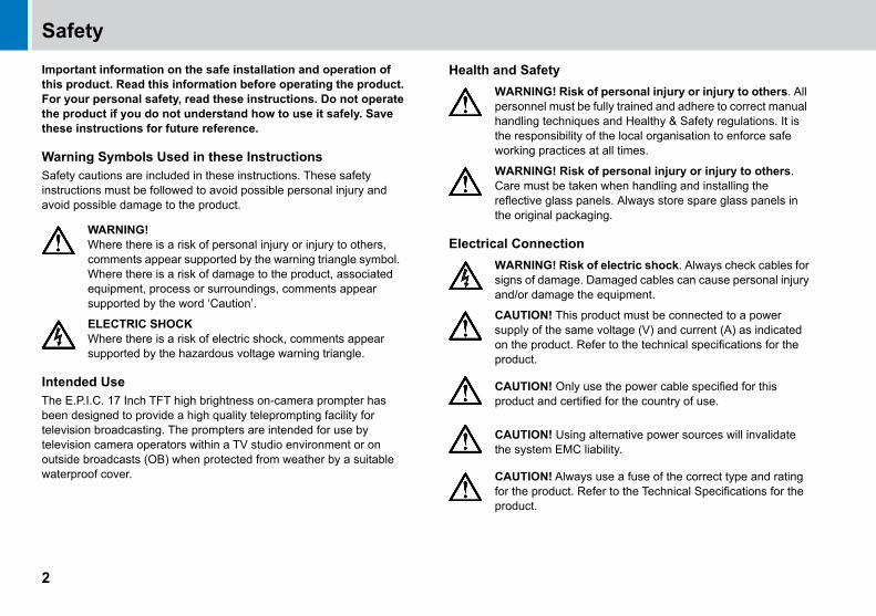
Health and Safety
Electrical Connection WARNING!Where there is a risk of personal injury or injury to others, comments appear supported by the warning triangle symbol. Where there is a risk of damage to the product, associated equipment, process or surroundings, comments appear supported by the word ‘Caution’.
ELECTRIC SHOCKWhere there is a risk of electric shock, comments appear supported by the hazardous voltage warning triangle.
WARNING! Risk of personal injury or injury to others. All personnel must be fully trained and adhere to correct manual handling techniques and Healthy & Safety regulations. It is the responsibility of the local organisation to enforce safe working practices at all times.
WARNING! Risk of personal injury or injury to others. Care must be taken when handling and installing the reflective glass panels. Always store spare glass panels in the original packaging.
WARNING! Risk of electric shock. Always check cables for signs of damage. Damaged cables can cause personal injury and/or damage the equipment.
CAUTION! This product must be connected to a power supply of the same voltage (V) and current (A) as indicated on the product. Refer to the technical specifications for the product.
CAUTION! Only use the power cable specified for this product and certified for the country of use.
CAUTION! Using alternative power sources will invalidate the system EMC liability.
CAUTION! Always use a fuse of the correct type and rating for the product. Refer to the Technical Specifications for the product.
2

Safety and About this Manual
Basic Electrical Insulation (Class 1 equipment)
Mounting and Installation
Water, Moisture and Dust
Ventilation
Operating Environment
Cleaning
Maintenance
About this ManualThe E.P.I.C. high brightness on-camera prompter is available with SDI connection ports. This manual describes the installation of the prompter onto a suitable camera support.
WARNING! This product is Class 1 equipment. For safe operation this equipment must be connected to a power supply that has a protective earth connection (US: ground).
WARNING! Before attempting to install or adjust the prompter assembly, the tilt axis of the head support must be securely locked horizontally.
WARNING! Do not install this product onto a camera support or other equipment that is not designed to support the weight of the product and its payload.
WARNING! Always ensure that all power and auxiliary communications cables are routed so that they do not present any danger to personnel. Take care when routing cables in areas where robotic equipment is in use.
WARNING! Protect the product from water, moisture and dust. The presence of electricity near water can be dangerous.
WARNING! When using this product outside, protect from rain using a suitable waterproof cover.
WARNING! Slots and openings are intended for ventilation purposes to ensure reliable operation of the product, and protect it from overheating. Do not block or cover any slots and openings.
CAUTION! The product should not be used outside the operating temperature limits. Refer to the product technical specifications for the operating limits for the product.
WARNING! Risk of electric shock. Always disconnect and isolate the product from the power supply before cleaning.
CAUTION! Do not use solvent or oil-based cleaners, abrasives or wire brushes.
WARNING! Servicing or repair of this product must only be performed by qualified and trained electrical engineers.
WARNING! The fitting of non-approved parts and accessories, or the carrying out of non-approved alterations or servicing can be dangerous and could affect the safety of the product. It may also invalidate the terms and conditions of the product warranty.
3

Components and Connections
On-Camera Prompter Key ComponentsThe illustration below highlights the key components used in a typical prompter installation.
1 Camera mounting plate
2 Counterbalance weights
3 Light shield
4 TallyPlus
5 Hood
6 Reflective glass
7 E.P.I.C. TFT monitor
8 ClockPlus-E
9 Monitor mounting brackets
10 Main prompter mounting extrusion
11 Hood mounting brackets
4

Components and Connections
Prompter Installation ComponentsThe following section describes the range of component parts available for a complete prompter installation using the E.P.I.C TFT monitor. Many of the parts listed are optional, depending on the specific requirements of the installation.
Camera Mounting Components
*Retracted length of the rods.
Prompter Mounting Components
No. Part Description
1 MT-BLACK Camera mounting plate for larger studio camera configurations
2 TR-7, TR-12 One pair of 7 or 12 inch* telescopic rods are required for use with the MT-BLACK plate
1 2
x2
No. Part Description
3 EXT-M or EXT-L Extrusion, medium or long
4 TFT-RDS Prompter monitor support rods
5 CBMT-R Counterbalance weights, 10 lb (4.5Kg)
6 CBMT-R20 Counterbalance weights, 20 lb (9Kg)
3
4
x2
x2
6 5
5

Components and Connections
Hood Components Clock & Tally Components
No. Part Description
7 MH-W Moulded hood, wide
8 LIGHTSHIELD-L Light shield cloth, Large
9 RGMH-W Reflective glass
7
8
9
No. Part Description
10 ClockPlus-E Clock/tally light
11 TallyPlus Tally light
10
11
6

Components and Connections
Box Contents Tools RequiredMetric Allen key set.
.
No. Part Description
1 EPIC17-ME 17” LED TFT Prompter Monitor
2 EPIC17-SDI2-ME 17” LED TFT Prompter Monitor with HD/SDI installed
7

Components and Connections
Prompter Monitor Connections Prompter Monitor Control Panel
1 AC power socket (IEC)
2 Fuse holder
3 Power switch
4 DC power socket (4 pin XLR)
5 HD-SDI 2 IN and OUT sockets
6 CVBS IN socket
7 CVBS OUT socket
8 LTC IN socket
9 Accessory OUT 12V 1A socket
10 Tally repeat OUT socket
11 OPTO sensor IN socket
12 HD-SDI 1 IN and OUT (Dual HD-SDI models only)
13 Talent monitor
1 Prompter power status LED
2 Prompter screen selection button
3 Video input selection button
4 Onscreen set up button
5 Onscreen menu navigation buttons
6 Remote connector (optional)
7 Picture rotation button
8 Monitor screen selection button
9 Monitor power button
8

Installation
Mounting the Camera and Extrusion
A pair of telescopic rods must be used to mount the prompter system. A camera mounting plate must be fitted between the head support and the camera body to allow installation of the prompter system. Different sizes of mounting plates are available, depending on the type of camera being used.
For more information on the camera mounting plate options available, see the section Camera Mounting Components on page 5.
Direct Mounting to the Camera Head Support1. Fit the camera and any fixing plate being used to the top of the
camera head support.
2. Screw the telescopic rods (TR7 or 12) into the mounting holes on the front of the camera head support.
WARNING! Before attempting to install or adjust the prompter assembly, the tilt axis of the head support must be securely locked horizontally (tilt axis).
9

Installation
MT-BLACK Mounting Plate1. Fit the camera head
support plate to the base of the MT-BLACK mounting plate.
2. Fit the mounting plate for the camera being used to the top of the MT-BLACK mounting plate, using the fixing screws provided.
3. Fit the MT-BLACK mounting plate to the camera support.
4. Fit the camera to the top of the MT-BLACK mounting plate.
10

Installation
5. Screw the telescopic rods (TR5, 7 or 12) into the mounting blocks on the MT-BLACK mounting plate.
Mounting the Extrusion1. Unscrew the twist locks on the telescopic rods to loosen the
extension sections.
2. Remove the two protective end caps from the extrusion.
3. Observing the correct orientation, slide the extrusion over the end clamps on the telescopic rods..
11

Installation
4. Centralise the extrusion, aligning the marker with the centre of the camera lens.
5. Turn the telescopic rods to tighten the clamps onto the rear of the extrusion. The clamps can be tightened securely by using an Allen key as a lever through the holes in the rods.
Mounting the Prompter Monitor
When the extrusion is fitted and correctly secured to the camera mount the prompter monitor can be fitted.
1. Unscrew the end caps from the two prompter monitor support rods.
WARNING! Before attempting to install or adjust the prompter monitor assembly, the tilt axis of the head support must remain securely locked horizontally.
WARNING! The prompter monitor must be isolated from the AC power supply during installation or adjustment.
12
Installation
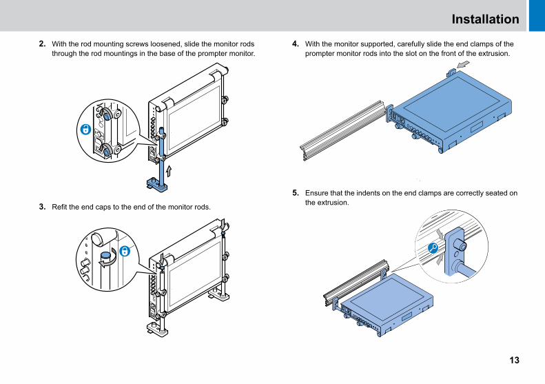
2. With the rod mounting screws loosened, slide the monitor rods through the rod mountings in the base of the prompter monitor.
3. Refit the end caps to the end of the monitor rods.
4. With the monitor supported, carefully slide the end clamps of the prompter monitor rods into the slot on the front of the extrusion.
5. Ensure that the indents on the end clamps are correctly seated on the extrusion.
13

Installation
6. Centralise the prompter monitor with the marker on the extrusion. Secure the monitor in position by tightening the clamping screw.
7. Slide the prompter monitor back and tighten the rod mounting screws on the base.
Assembling and Fitting the HoodsA range of hoods are available for use with the E.P.I.C. on-camera prompter. The hoods are available in solid moulded or folding versions, in various sizes, to suit the camera and monitor being used in the installation. Fixing brackets are supplied for use with the hood variant being installed.
For more information on the hoods available see the section Hood Components on page 6.Assembling the Moulded Hoods - Both Sizes
1. Align the hood bracket and two fixing screws with the holes in the side of the hood.
2. Tighten the fixing screws to secure the hood bracket in position.
3. Repeat steps 1 and 2 for the opposite hood bracket.
14

Installation
Folding Hoods - Initial AssemblyThe hoods are supplied flat-packed and require some basic assembly.
When used for outside broadcast and other portable applications, the hoods can easily be folded flat again for transportation.
1. Fold the back plate of the hood out away from the top flag.
2. Fold the side flags outwards.
3. Align the two eyelets in the top flag with the tabs and twist to lock.
15

Installation
4. Align the single eyelets in both the side flags with the tabs and twist to lock.
5. Fold the Velcro flaps down over the top and side flags.
Assembling the Extra Wide Folding Hood1. Align the holes in the prompter and angle brackets with the two
threaded holes in the mounting plate. Tighten the fixing screws to secure the whole bracket assembly.
2. Align the assembled bracket with the holes in the rear of the hood. Tighten the fixing screws to secure the bracket in position.
3. Repeat steps 1 and 2 for the opposite hood bracket.
16

Installation
Fitting the HoodsWhen the hood has been assembled, it can be installed onto the prompter assembly.
Fitting the Moulded Hood - Both Sizes1. Align the clamps on the ends of the hood brackets with the slot in
the top of the extrusion. Slide the hood assembly onto the extrusion.
2. Centralise the hood assembly with the lens and prompter monitor, and tighten the clamp locks to secure firmly in position.
Fitting the Extra Wide Folding Hood1. Align the clamps on the ends of the hood brackets with the slot in
the top of the extrusion. Slide the hood assembly onto the extrusion.
2. Centralise the hood assembly with the lens and prompter monitor, and tighten the clamp locks to secure firmly in position.
17

Installation
Fitting the Extrusion End Caps
Firmly press the extrusion end caps into place at both ends of the extrusion.
Adjusting the Vertical Hood PositionThe vertical position of the hood must be adjusted to centralise it with the camera lens.
Moulded Hoods and Extra Wide Folding Hood1. Loosen the two side clamp screws to adjust the position of the
hood on the rods.
2. Adjust the vertical position of the hood to centralise it with the camera lens and fully re-tighten the clamp screws.
Adjusting the Prompter Assembly PositionThe horizontal position of the prompter assembly must be adjusted to optimise its position relative to the camera lens.
MT-BLACK Mounting Plate Adjustment1. Loosen the twist locks on the telescopic rods and move the
prompter assembly back until the hood overlaps the camera lens.
2. Tighten the twist locks to secure the assembly.
WARNING! When the hood has been installed, the supplied extrusion end caps must be fitted to protect against personal injury.
18

Installation
Fitting the Reflective Glass Panel
When the hood has been installed, the reflective glass panel can be fitted to the prompter assembly.
Panel OrientationFor the E.P.I.C. prompter to display images, it is essential that the reflective side of the glass is installed facing outwards. The reflective side of the glass can be established as follows:
Carefully hold a blunt object such as a coin against the surface of the glass.
If the object is being held against the reflective side, there will be no gap (depth of the glass) before the reflection.
Fitting the Glass PanelThe installation procedure for the glass panel is the same on all types of hood, although there are more fixing screws on the larger hoods.
1. Remove all the fixing screws from the top of the hood to release the top glazing bar.
2. Carefully position the glass panel on the bottom glazing bar inside the hood.
WARNING! Risk of personal injury or injury to others. Care must be taken when handling and installing the reflective glass panels. Always store spare glass panels in the original packaging.
WARNING! Only use the correct size glass panel designed for the installed hood.
19

Installation
3. With the glass supported at all times, replace the top glazing bar and secure with the fixing screws.
20

Installation
Fitting the TallyPlus1. Fit the mounting bracket to the rear of the TallyPlus using the two
fixing screws provided. The mounting bracket can be fitted to the lower set of mounting holes to increase the height of the TallyPlus above the hood.
2. Fit the TallyPlus to the hood, aligning the fixing holes in the brackets and securing with the two fixing screws provided.
21

Installation
Fitting the ClockPlus-E
1. Remove the four fixing screws from the Tally Light cover.
2. Remove the Tally Light cover from the front of the monitor to expose the interface connector for the ClockPlus-E.
3. Align the ClockPlus-E connector with the interface connector on the monitor. Fit the the ClockPlus-E to the monitor.
4. Tighten the thumbscrews on either side of the ClockPlus-E.
WARNING! Before attempting to install or adjust accessories, the tilt axis of the head support must be securely locked horizontally (tilt axis).
The Tally Light cover must be removed before fitting the ClockPlus-E
22

Installation
Adjusting the Talent Monitor1. Loosen the clamp on the side of talent monitor.
2. Hold the talent monitor. Pull the securing pin, located underneath the prompter, to release the talent monitor from its housing.
3. Allow the talent monitor to swing down vertical. Position as desired and tighten the clamp to secure in place.
.
The talent monitor can be left unlocked to allow it to remain vertical when the camera support is tilted up or down.
23

Installation
Fitting the Light Shield Cloth
A light shield cloth must be fitted between the camera lens and the rear of the hood to prevent light entering behind the glass. This is essential for the prompter to display text clearly.
Different cloths are available depending on the installation:
Folding Hood Light Shield ClothThe folding hoods have the light shield cloth permanently attached. There is a draw string to shape the cloth opening around the camera lens.
Moulded Hood Light Shield Cloth1. Secure the light shield
cloth to the Velcro strips on the rear of the hood.
2. On light shield cloths with the ‘keyhole’ cut out, seal the join with the Velcro strips on the cloth.
Fitting the Counterbalance WeightsThe prompter installation must have counterbalance weights fitted to the rear of the mounting to compensate for the front-heavy effect of the prompter monitor and hood.
1. Unscrew the caps from the mounting rods protruding from the rear of the mounting plate.
2. Carefully slide the counterbalance weights onto the rods.
CAUTION! Ensure that the light shield cloth is only loosely fitted around the body of the servo lens to allow it to continue operating freely.
OR
CBMT-R CBMT-R20
24

Installation
Balancing and Adjustments
Balancing is achieved by correctly positioning the counterbalance weights. Other adjustments can also be made to the prompter assembly position if this is a requirement of the installation.
Basic Balancing1. Slide the counterbalance weights along the rods and secure in
position with the two clamping screws. Unlock the tilt axis and check the fore and aft balance of the payload.
2. If the payload is not correctly balanced, lock the tilt axis and:
a) If the payload is falling forward (front heavy), move the counterbalance weights further back on the rods.
b) If the payload is falling backwards (rear heavy), move the counterbalance weights further forward on the rods.
3. Secure the counterbalance weights and re-check the balance.
Splitting the Counterbalance WeightsIf the counterbalance weights have too much effect, even in the closest mounting position, one half can be removed.
1. If fitted, remove the counterbalance weights from the prompter assembly.
2. Using a 4 mm Allen key, remove the two screws securing the weights together.
3. Separate the weights and refit one of the halves with the clamping screws.
WARNING! After fitting or adjusting the prompter assembly and any accessories, the payload must be correctly re-balanced.
25

Installation
Additional Adjustments
Additional adjustments can be made to the camera mounting plate and prompter assembly if balancing cannot be achieved or there are specific requirements for an installation.
MT-BLACK AdjustmentsThe top camera mounting plate can be moved to offset the position of the camera, by removing the bottom screws with a 4 mm Allen key and reseating the assembly in the other four screw holes.
The rod mounting blocks can be moved to different screw hole positions on the mounting plate as required, by removing the block fixing screws with a 5 mm Allen key.
Camera Support AdjustmentsIf necessary, further balancing and positional adjustments can be made to the camera head support (manual or robotic).
WARNING! Before attempting to adjust the prompter assembly, the tilt axis of the head support must be securely locked horizontally (tilt axis).
WARNING! Before attempting to adjust the positions of the mounting blocks on the camera plate, the counterbalance weights and prompter assembly must be removed.
26

Installation
Connecting the Prompter Monitor
Video Connections
Connect the video signal (for prompter display) using one of the following options.
HD/SDI Connection
Dual HD/SDI Connection (Optional)
CVBS Connection
LTC Connection
Connection using composite video or HD/SDI to the prompter monitor should always be made with screened 75Ω coaxial cable.The video cable screen should be connected to earth (ground) at both ends.
27

Installation
Additional Accessory ConnectionsAutoscript accessories such as tally sensors or the ClockPlus-E can also be connected to the monitor.
Opto Sensor ConnectionProvides connection for an Autoscript external opto sensor attached to a camera tally light to activate the built-in tally light on the monitor.
Tally Light Repeat ConnectionProvides connection for an Autoscript tally device such as the TallyPlus to relay the tally indication signal being used by the monitor.
Accessory DC Connection
Provides a 12V DC supply to operate external accessories such as the Autoscript TallyPlus.
For more information on the specifications of the accessory sockets, see the section Connections Data on page 35.
CAUTION! The accessory DC out socket is intended for use with approved Autoscript accessories only. Do not exceed the current output limit of the product when powering auxiliary devices.
28

Installation
Power ConnectionsThe prompter monitor can be powered by either an AC supply or a 12VDC supply.
AC Power Connection
DC Power Connection
Powering UpBefore powering up, ensure that all external cable connections have been secured correctly.
To power up, operate the on/off rocker switch.
WARNING! This product is Class 1 equipment. For safe operation this equipment must be connected to a power supply that has a protective earth connection (US: ground). Ensure that an IEC 3-core AC supply cable is used.
CAUTION! When powering the product on DC power, use a regulated 12V DC power source capable of supplying at least 5A.
29

Configuration
Control Panel ButtonsThe buttons on the control panel are used to configure the setup of the prompter monitor screen. The buttons have legends to indicate their function, and are back-illuminated.
The control panel buttons are clustered in four distinct groups.
Direct Access ButtonsThese two buttons provide quick access to common functions.
Setup Button.
Prompter Button.
On-Air Monitor Buttons.
Power Status LED.
Button Button Function
INPUT SELECTION button steps to the next available video input.
PICTURE ROTATION button steps through all four combinations of horizontal and vertical scanning directions, allowing the correct picture orientation for direct or mirror viewing to be set.
Button Button Function
SETUP button to activate the on-screen engineering setup menu.
I/P
Button Button Function Colour Status
PROMPTER button allows the script or vanity image to be displayed on the prompter monitor.
When display active.
When display inactive.
Button Button Function Colour Status
The power button provides a supply to the vanity monitor. The vanity monition must be unlocked to become active.
When power active.
When power inactive.
ON-AIR MONITOR button allows the script or vanity image to be displayed on the vanity monitor.
When display active.
When display inactive.
Button Button Function
POWER STATUS button illuminates green when a valid power supply is detected.
30

Configuration
Menu ButtonsThis group of five buttons are for on-screen menu navigation.
User Monitor Setup MenusThe user monitor setup menus are shown in the following table, with sub menus and any parameters that can be changed by the user.
Where there is a variable parameter in a menu, the maximum and minimum limits are shown either side of the current set value.
The control range of some parameters is limited intentionally to prevent erratic operation.
The menus are accessed by pressing the SETUP key, and navigated using the MENU and four ARROW keys.Button Button Function
MENU button:• Turns on screen display (OSD) menus ON or OFF
• Goes back to the previous menu page
DOWN ARROW button:• Moves the selector to the next function
UP ARROW button:• Moves the selector to the previous function
RIGHT ARROW button:• Increases the OSD parameter value
• Enters a sub menu from a higher menu
• Confirms selection of an OSD function
LEFT ARROW button:• Decreases the OSD parameter value
Sub Menus Parameters Description
System Setup Menu - Clock Setup Menu
TC Source • Ext LTC
• CVBS1
• CVBS2
Allows TC Source to be selected.
12 / 24h Mode • 12h
• 24h
Allows the clock to be displayed in 12 hour or 24 hour format.
System Setup Menu - Tally Setup Menu
Tally Brightness 0 - 31 Provides control over the brightness of the red tally light on the monitor.
Opto Sensitivity 0 - 31 Changes the sensitivity of the opto sensor input for different types of sensor.
System Setup Menu - HDSDI Status
No HDSDI setup options fitted.
System Setup Menu - Switch Brightness Menu
In-Use setting 2 - 31 Provides control over the brightness of the illuminated switches.
31

Configuration
Remote Control Configuration Setup MenuThe E.P.I.C. TFT monitors are shipped with the Remote Control configuration socket blanked as standard. However, this can be included as an optional extra on request. When installed, the Remote Control configuration menus provide options for adjusting parameters to suit the operators requirements.
This is accessed by pressing the SETUP key, and navigated using the MENU and four ARROW keys.
LCD Parameters MenuThe E.P.I.C. TFT monitors are shipped with configured display settings which have been optimised for prompting text display. However, the LCD parameter menus provide options for adjusting settings such as contrast, colour and picture format ratios.
This is accessed by pressing the SETUP key, and navigated using the MENU and four ARROW keys.
Sub Menus Parameters Description
System Setup Menu - Switch Brightness Menu (Cont.)
Dimmed setting 0 - 31 Provides control over the dim setting of the illuminated switches.
System Setup Menu - Over-Temp Menu
O/T brightness 5 - 25 Provides control over the over-temp brightness setting.
System Setup Menu - Service Menu
System Status Clock/TallyHDSDIREMOTE PCB
Displays system status.
Version Software Version
Displays the software version installed.
Video Reset NOYES
Allows the video settings to be reset.
Factory Reset NOYES
Allows the system to be reset back to factory default settings.
32

Maintenance
Routine MaintenanceThe E.P.I.C. TFT on-camera prompters requires minimal routine maintenance, apart from checking the connections and overall operation periodically.
Routine checksDuring use, check the following:
• Check cables for signs of wear or damage. Replace as necessary.
• Check that all cables are connected properly.
Cleaning
Prompter Assembly CleaningDuring normal use the only cleaning required should be a regular wipe over with a dry, lint-free cloth. Dirt accumulated during storage or periods of disuse may be removed with a vacuum cleaner. Particular attention should be paid to all connection ports on the monitor.
Reflective Glass Cleaning
Care and cleaning of the reflective glass panel is essential for increased life and prompting display performance.
No solvents or glass cleaners should be used. Only use clean water and a damp lens cloth when cleaning. Do not apply excessive pressure to the reflective glass panel during the cleaning process.
Changing the Fuse
1. Switch OFF and disconnect the power. It is not necessary to remove the payload or other cabling.
2. Using a flat-blade screwdriver, remove the fuse holder and discard the blown fuse.
3. Replace the fuse, then reinstall the fuse holder.
WARNING! Risk of electric shock. Disconnect and isolate the product from the power supply before cleaning.
WARNING! Risk of personal injury or injury to others. Care must be taken when handling or cleaning the reflective glass panels. Always store spare glass panels in the original packaging.
WARNING! Risk of electric shock. Disconnect the power cable. Fuses must only be changed by a trained and competent person.
CAUTION! The replacement fuse must be the correct rating: Type 20mm ceramic tube fuse rated at 2A 250V AC
33

Troubleshooting
Fault Check Comments
The monitor is not powering up.
Check that the AC power source is connected and secured. See the section Powering Up on page 29
Check that the DC power source is connected and secured.
Check that AC power is being supplied to the DC adaptor.
Check the fuse and replace if necessary. See the section Changing the Fuse on page 33
No prompting text or video display on the monitor screen.
Check that the video cable is connected and the video source is active. See the section Video Connections on page 27
Use the INPUT SELECTION button to step through to the correct video input channel.
See the section Direct Access Buttons on page 30
The prompting text display is the wrong orientation for viewing.
Use the PICTURE ROTATION button to select the correct orientation. See the section Direct Access Buttons on page 30
34

Technical Specification
Prompter Physical Data
*Excluding controls/connectors.
On-Air Monitor Physical Data
*Excluding controls/connectors.
Environmental DataOperating temperature range . . . . . . . . 5°C to +40°C (41°F to +104°F)Storage temperature range . . . . . . . .-20°C to +60°C (-4°F to +140°F)
Electrical DataVideo inputs . . . . . . . . . . . . . . . . . . . . . . . CVBS, HD/SD-SDI (Option) AC Power input. . . . . . . . . . . . . . . . . . . . . . . . . . . . . . . . .100-240V ACDC Power input . . . . . . . . . . . . . . . . . . . . . . . . . . . . . . . . . . . . 12V DC*For models with the HD-SDI Option add 0.2A (2.4W) @ 12V DC or + 2VA AC to the power consumption figure.
Prompter Display DataBrightness . . . . . . . . . . . . . . . . . . . . . . . . . . . . . . . . . . . . . . . 1600 nitsAspect ratio . . . . . . . . . . . . . . . . . . . . . . . . . . . . . . . . . . . . . . . . . . . 4:3Resolution . . . . . . . . . . . . . . . . . . . . . . . . . . . . . . 1280 x 1024 (SXGA)
On-Air Monitor Display DataBrightness . . . . . . . . . . . . . . . . . . . . . . . . . . . . . . . . . . . . . . . . 400 nitsAspect ratio . . . . . . . . . . . . . . . . . . . . . . . . . . . . . . . . . . . . . . . . . . 16:9Resolution . . . . . . . . . . . . . . . . . . . . . . . . . . . . . 1920 x 1080 (Full HD)
Connections Data
DC Power SocketConnector type: 4 pin XLR plug.
Width* 47.5 cm (18.75 in.)
Height* 5.5 cm (2.1 in.)
Depth* 33.5 cm (13.1 in.)
Weight 7.6kgs (16.7lbs) Including On-Air Monitor
Width* 41 cm (16 in.)
Height* 2 cm (0.75 in.)
Depth* 28.5 cm (11.25 in.)
Weight 7.6kgs (16.7lbs) Including Prompter
Pin Signal
1 GROUND (connected to monitor chassis)
2 TALLY LOGIC INPUT (>2.5V DC in = Tally light ON, <2V DC in = Tally light OFF)
4 +12V DC
35

Technical Specification
Composite Video In and OutConnector type: 75Ω BNC socket.
HD/SDI In and OutConnector type: 75Ω BNC socket.
Fully compliant with SMPTE 259M-C and SMPTE 292M standards.
Opto Sensor InputConnector type: 3.5 mm mono jack socket.
Connection for an external Autoscript opto sensor to activate the built-in tally light on the monitor. The sensor is attached to the camera tally light and allows the monitor to mimic the operation of the camera tally.
Alternatively, the tally light can be triggered by connecting a contact closure (ground loop) to the opto sensor socket, or applying a positive logic voltage to the TALLY LOGIC input on pin 2 of the XLR socket.
Sensor/Grounding Loop Specification:
• Light Dependent resistor, 20kΩ at 10 Lux, 5KΩ at 100 Lux or (grounding) contact closure
• High illumination or contact closure = Tally light ON• Low illumination or contact open = Tally light OFF
Tally Repeat OutputConnector type: 3.5 mm mono jack socket.
Open collector output giving contact closure to ground when the built-in monitor tally light is ON. Intended to be used to operate an external tally device such as the Autoscript ClockPlus-E.
Accessory DC OutputConnector type: 3.5 mm mono jack socket.
Provides a 12V DC supply to operate external accessories such as the Autoscript +Tally-Plus+. Fused internally with a resettable fuse.
LTC InputConnector type: 3 pin socket
Pin connections conform to the SMPTE 12M standard.
Technical specifications are subject to change without notice.
Pin Signal
Centre Composite Video In (PAL or NTSC)
Outer GROUND (Cable screen)
Pin Signal
Centre HD/SDI In
Outer GROUND (Cable screen)
Pin Signal
Tip HOT
Sleeve GROUND
Pin Signal
Tip HOT
Sleeve GROUND
Pin Signal
Tip +12V DC
Sleeve GROUND
36

General Notices
FCC Certification
FCC NoticeThis product complies with the limits for a Class A digital device, pursuant to Part 15 of the FCC Rules. These limits are designed to provide reasonable protection against harmful interference in a commercial environment. This equipment generates, uses and can radiate radio frequency energy and, if not installed and used in accordance with the instructions, may cause harmful interference with radio communications. Operation of this product in a residential area is likely to cause harmful interference, in which case you will be required to correct the interference at your own expense.
FCC WarningChanges or modifications not expressly approved by the party responsible for compliance could void the user’s authority to operate the equipment.
FCC Declaration of ConformityThis product complies with Part 15 of the FCC Rules. Operation is subject to the following two conditions:
1.This product may not cause harmful interference.
2.This product must accept any interference received, including interference that may cause undesired operations.
Declaration of Conformity
Vitec Videocom Limited declares that this product has been manufactured in accordance with BS EN ISO 9001:2008.
This product complies with the following EU Directives:
• Low Voltage Directive 2006/95/EC
• EMC Directive 2004/108/EC
Compliance with these directives implies conformity to applicable harmonized European standards (European Norms) which are listed on the EU Declaration of Conformity for this product or product family. A copy of the Declaration of Conformity is available upon request.
Environmental considerations
ROHS Compliance StatementVitec Videocom Limited is compliant with the European Union Directive 2002/95/EC Restrictions of Hazardous Substances (RoHS) that restricts the use of hazardous substances in Electrical and Electronic Equipment.
E.P.I.C. PrompterEPIC17
17-SDIEPIC
37

General Notices
European Union Waste of Electrical and Electronic Equipment (WEEE) Directive (2002/96/EC)
This symbol marked on the product or its packaging indicates that this product must not be disposed of with general household waste. In some countries or European Community regions separate collection systems have been set up to handle the recycling of electrical and electronic waste products. By ensuring this product is disposed of correctly, you will help prevent potentially negative consequences for the environment and human health. The recycling of materials helps conserve natural resources.
Visit our website for information on how to safely dispose of this product and its packaging.
In countries outside the EU:Dispose of this product at a collection point for the recycling of electrical and electronic equipment according to your local government regulations.
Pollution statementThis equipment is designed for operation in Pollution Degree 2 environments.
38

A VAutoscript
itec Group brand
Publication part No. EPIC17-4980/1
www.autoscript.tv