Embed Size (px)
Citation preview
3 Industrial Communication NetworksAutomation Overview
EPFL, Spring 2017
Industrial Automation | 2017 2
3 Industrial Communication Networks
3.1 Field bus principles
3.2 Field bus operation
3.3 Standard field busses
3.4 Industrial wireless communication
Industrial Automation | 2017 3
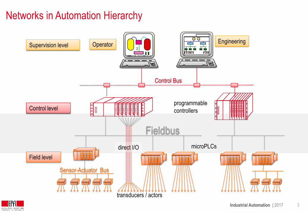
transducers / actors
Networks in Automation Hierarchy
Hierarchy
Sensor-Actuator Bus
Fieldbus
programmable
controllers
Control Bus
Supervision level
Control level
Field level
EngineeringOperator
2
direct I/O microPLCs
Course
Industrial Automation | 2017 4
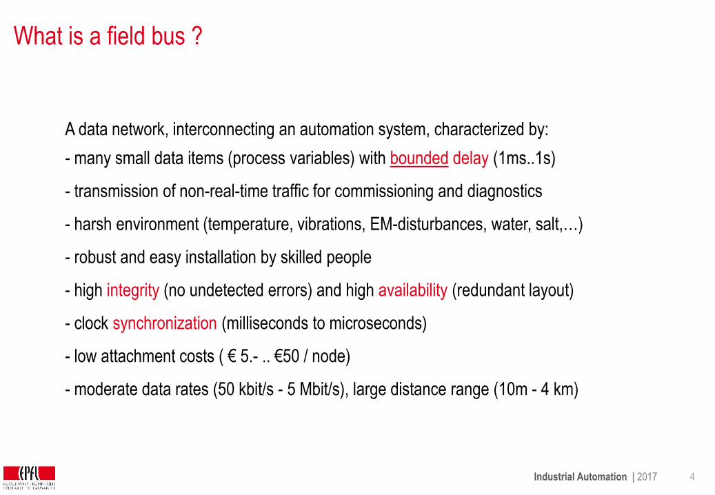
What is a field bus ?
A data network, interconnecting an automation system, characterized by:
- many small data items (process variables) with bounded delay (1ms..1s)
- transmission of non-real-time traffic for commissioning and diagnostics
- harsh environment (temperature, vibrations, EM-disturbances, water, salt,…)
- robust and easy installation by skilled people
- high integrity (no undetected errors) and high availability (redundant layout)
- clock synchronization (milliseconds to microseconds)
- low attachment costs ( € 5.- .. €50 / node)
- moderate data rates (50 kbit/s - 5 Mbit/s), large distance range (10m - 4 km)

Industrial Automation | 2017 5
Expectations
- reduce cabling
- increased modularity of plant (each object comes with its computer)
- easy fault location and maintenance
- simplify commissioning (mise en service, IBS = Inbetriebssetzung)
- simplify extension and retrofit
- off-the-shelf standard products to build “Lego”-control systems
Industrial Automation | 2017 6
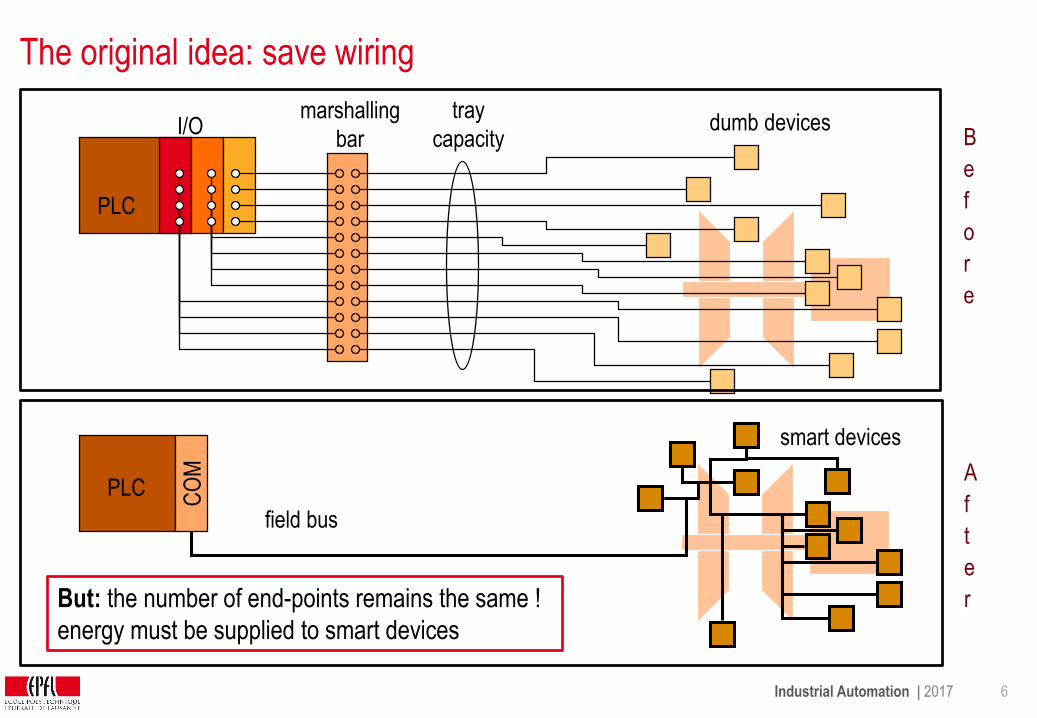
The original idea: save wiring
PLC
But: the number of end-points remains the same !
energy must be supplied to smart devices
field bus
CO
M
marshalling
barI/O
PLC
smart devices
tray
capacity B
e
f
o
r
e
A
f
t
e
r
dumb devices
Industrial Automation | 2017 7
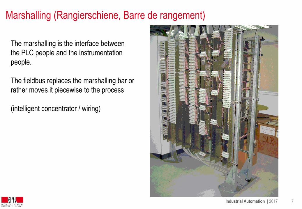
Marshalling (Rangierschiene, Barre de rangement)
The marshalling is the interface between
the PLC people and the instrumentation
people.
The fieldbus replaces the marshalling bar or
rather moves it piecewise to the process
(intelligent concentrator / wiring)

Industrial Automation | 2017 8
Different classes of field busses
poll time, milliseconds
10
100
1000
10,000
10 100 1000 10,000
Sensor BusSimple devicesLow costBus powered Short messages (bits)Fixed configuration Not intrinsically safeTwisted pairMax distance 500m
Low Speed FieldbusProcess instruments, valvesMedium costBus-powered (2 wire)Messages: values, statusIntrinsically safeTwisted pair (reuse 4-20 mA)Max distance 1200m
High Speed FieldbusPLC, DCS, remote I/O, motorsMedium costNot bus poweredMessages: values, statusNot intrinsically safeShielded twisted pairMax distance 800m
Data NetworksWorkstations, robots, PCsHigher costNot bus powered Long messages (e-mail, files)Not intrinsically safeCoax cable, fiberMax distance miles
PV 6000
SP 6000
Honeywell
AUTO
1
One bus type cannot serveall applications and all device types efficiently...
source: ABB
frame size(bytes)
Industrial Automation | 2017 9
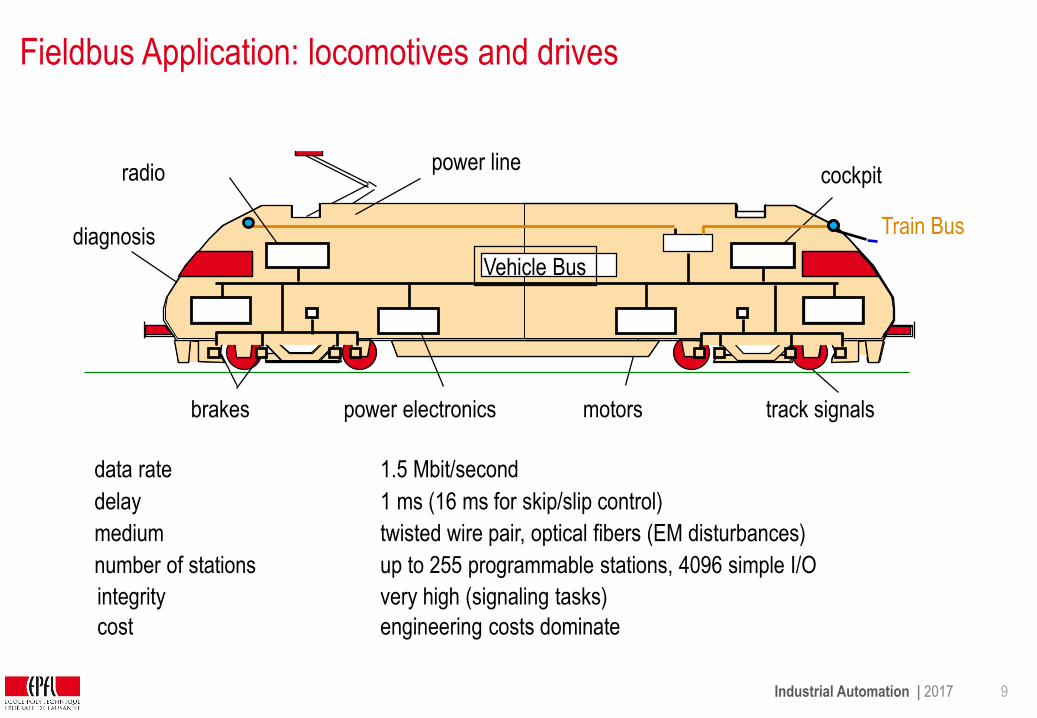
Fieldbus Application: locomotives and drives
cockpit
motorspower electronicsbrakes
power line
track signals
Train Busdiagnosis
radio
data rate
delay
medium
number of stations
1.5 Mbit/second
1 ms (16 ms for skip/slip control)
twisted wire pair, optical fibers (EM disturbances)
up to 255 programmable stations, 4096 simple I/O
Vehicle Bus
cost engineering costs dominate
integrity very high (signaling tasks)
Industrial Automation | 2017 10
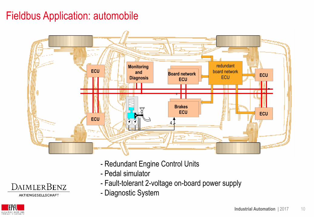
Fieldbus Application: automobile
- Electromechanical wheel brakes
- Redundant Engine Control Units
- Pedal simulator
- Fault-tolerant 2-voltage on-board power supply
- Diagnostic System
Board networkECU
Monitoringand
Diagnosis
BrakesECU
4
redundantboard network
12V und 48VECU
ECU
ECU
c
ECU
redundant
board network
ECU
Industrial Automation | 2017 11
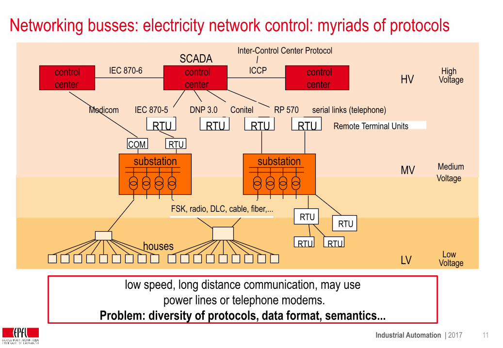
Networking busses: electricity network control: myriads of protocols
low speed, long distance communication, may use
power lines or telephone modems.
Problem: diversity of protocols, data format, semantics...
houses
substation
Modicom
ICCPcontrol
center
Inter-Control Center Protocol
IEC 870-6HV
MV
LV
HighVoltage
Medium
Voltage
LowVoltage
SCADA
FSK, radio, DLC, cable, fiber,...
substation
RTU
RTU RTU
RTU
COM
RTU RTU RTU Remote Terminal UnitsRTU
RTU
IEC 870-5 DNP 3.0 Conitel RP 570
control
center
control
center
serial links (telephone)

Industrial Automation | 2017 12
Fieldbus over a wide area: example wastewater treatment
Pumps, gates, valves, motors, water level sensors, flow meters, temperature sensors, gas
meters (CH4), generators, etc are spread over an area of several km2. Some parts of the
plant have to cope with explosives.
Industrial Automation | 2017 13
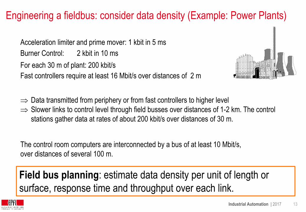
Engineering a fieldbus: consider data density (Example: Power Plants)
Data transmitted from periphery or from fast controllers to higher level
Slower links to control level through field busses over distances of 1-2 km. The control
stations gather data at rates of about 200 kbit/s over distances of 30 m.
Acceleration limiter and prime mover: 1 kbit in 5 ms
Burner Control: 2 kbit in 10 ms
For each 30 m of plant: 200 kbit/s
Fast controllers require at least 16 Mbit/s over distances of 2 m
The control room computers are interconnected by a bus of at least 10 Mbit/s,
over distances of several 100 m.
Field bus planning: estimate data density per unit of length or
surface, response time and throughput over each link.

Industrial Automation | 2017 14
3 Industrial Communication Networks
3.1 Field bus principles
3.2 Field bus operation
3.3 Standard field busses
3.4 Industrial wireless communication
Industrial Automation | 2017 15
Assessment
• What is a field bus ?
• Which of these qualities are required: 1 Gbit/s operationFrequent reconfigurationPlug and playBound transmission delayVideo streaming
• How does a field bus support modularity ?
•Which advantages are expected from a field bus ?
Industrial Automation | 2017 16
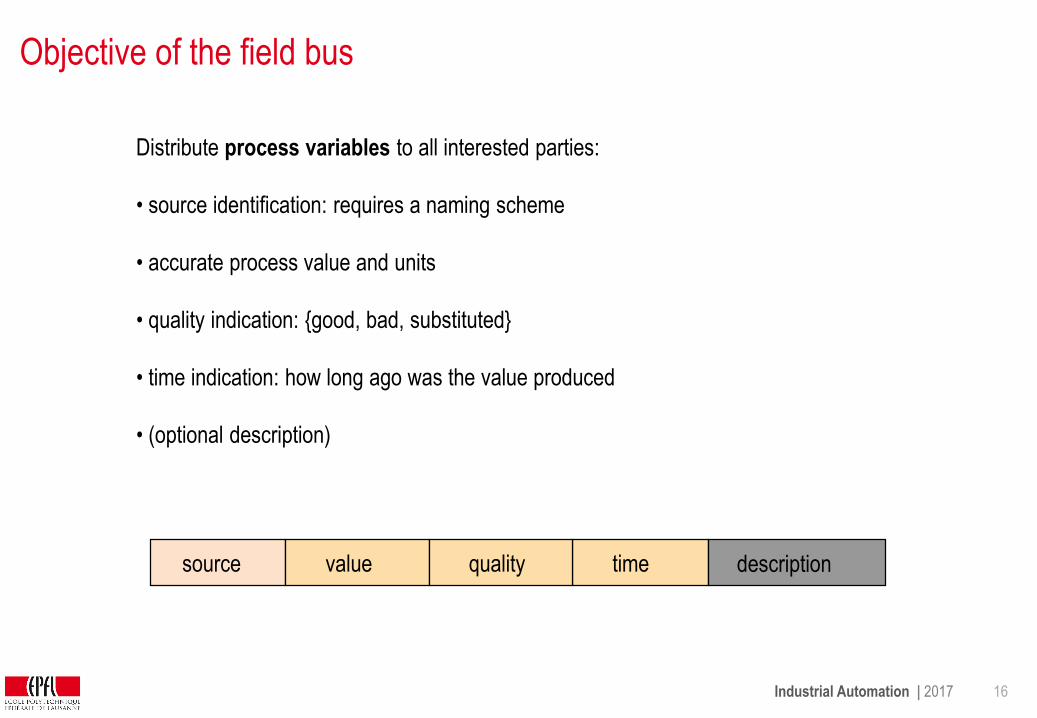
Objective of the field bus
Distribute process variables to all interested parties:
• source identification: requires a naming scheme
• accurate process value and units
• quality indication: {good, bad, substituted}
• time indication: how long ago was the value produced
• (optional description)
timequalityvaluesource description

Industrial Automation | 2017 17
Data format
In principle, the bus could transmit the process variable in clear text (even using XML..)
However, this is quite expensive and only considered when the communication network
offers some 100 Mbit/s and a powerful processor is available to parse the message
More compact ways such as ASN.1 have been used in the past with 10 Mbit/s Ethernet
Field busses are slower (50kbit/s ..12 Mbits/s) and thus more compact encodings are used.
valuelengthtypeASN.1: (TLV)
minimum
Industrial Automation | 2017 18
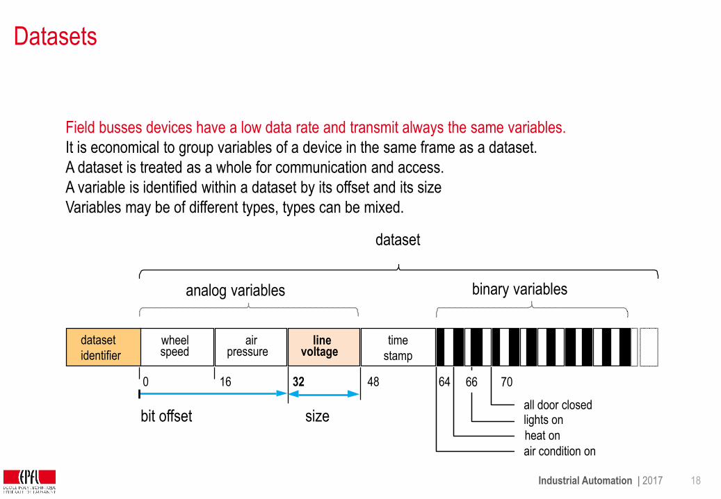
Datasets
wheelspeed
airpressure
linevoltage
time
stamp
analog variables binary variables
all door closedlights on
heat on
air condition on
bit offset
16 32 480 64 66 70
size
Field busses devices have a low data rate and transmit always the same variables.
It is economical to group variables of a device in the same frame as a dataset.
A dataset is treated as a whole for communication and access.
A variable is identified within a dataset by its offset and its size
Variables may be of different types, types can be mixed.
dataset
identifier
dataset
Industrial Automation | 2017 19
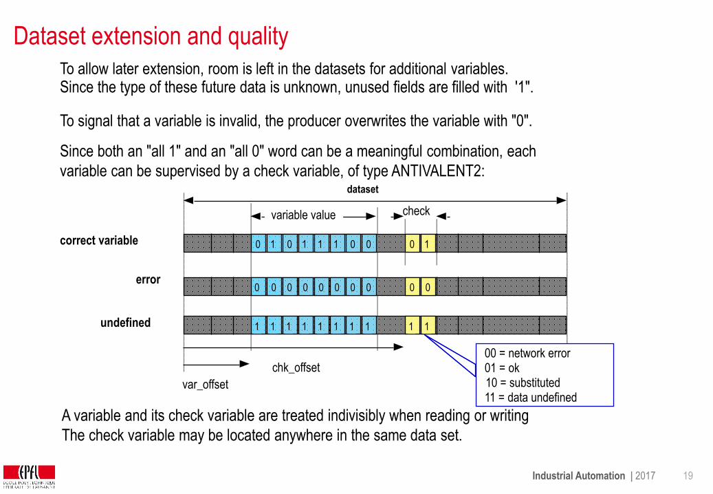
Dataset extension and qualityTo allow later extension, room is left in the datasets for additional variables.Since the type of these future data is unknown, unused fields are filled with '1".
To signal that a variable is invalid, the producer overwrites the variable with "0".
Since both an "all 1" and an "all 0" word can be a meaningful combination, each
variable can be supervised by a check variable, of type ANTIVALENT2:
A variable and its check variable are treated indivisibly when reading or writing
The check variable may be located anywhere in the same data set.
dataset
0 1 0 1 1 1 0 0 0 1
check
0 0 0 0 0 0 0 0
1 1 1 1 1 1 1 1
0 0
1 1
correct variable
error
undefined
variable value
var_offset
chk_offset
10 = substituted
00 = network error01 = ok
11 = data undefined
Industrial Automation | 2017 20
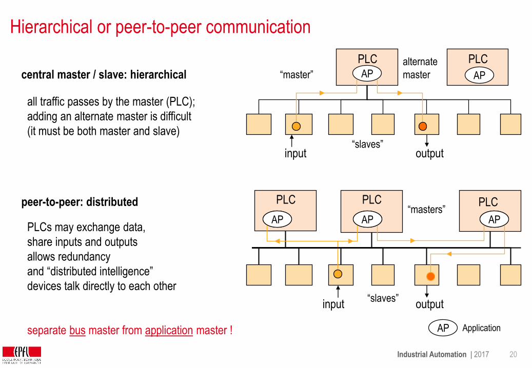
PLCs may exchange data,
share inputs and outputs
allows redundancy
and “distributed intelligence”
devices talk directly to each other
separate bus master from application master !
Hierarchical or peer-to-peer communication
AP
all traffic passes by the master (PLC);
adding an alternate master is difficult
(it must be both master and slave)
input output
input output
PLC
PLC PLC PLC
PLC
central master / slave: hierarchical
peer-to-peer: distributed
“slaves”
“master”
“slaves”
“masters”
alternate
master AP
APAPAP
AP Application

Industrial Automation | 2017 21
applicationprocessor
applicationprocessor
BroadcastsMost variables are read in 1 to 3 different devices
Broadcasting messages identified by their source (or contents) increases efficiency.
…
instances
…
=
variable
applicationprocessor
plantimage
plantimage
plantimage
=
distributeddatabase
Bus refreshes plant image in the background
Each station snoops the bus and reads the variables it is interested in.
Each device is subscribed as source or as sink for some process variables
Only one device is source of a certain process variable (otherwise collision)
Replicated traffic memories can be considered as "caches" of the plant state
(similar to caches in a multiprocessor system), representing part of the plant image.
bus
plantimage
Industrial Automation | 2017 22
Transmission principle
The previous operation modes made no assumption, how data are transmitted.
The actual network can transmit data
• cyclically (time-driven) or
• on demand (event-driven),
• or a combination of both.
Industrial Automation | 2017 23
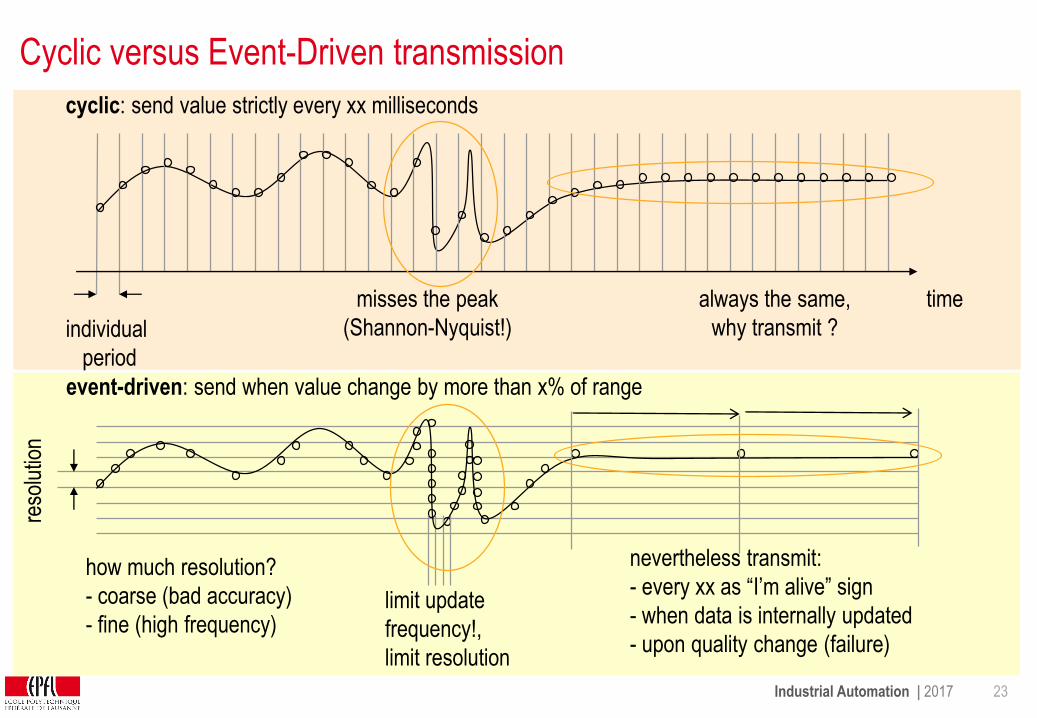
Cyclic versus Event-Driven transmission
event-driven: send when value change by more than x% of range
limit update
frequency!,
limit resolution
cyclic: send value strictly every xx milliseconds
nevertheless transmit:
- every xx as “I’m alive” sign
- when data is internally updated
- upon quality change (failure)
misses the peak
(Shannon-Nyquist!)
always the same,
why transmit ?
how much resolution?
- coarse (bad accuracy)
- fine (high frequency)
time
individual
period
reso
lutio
n
Industrial Automation | 2017 24
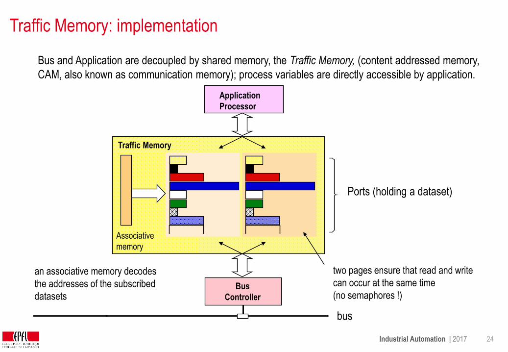
Traffic Memory: implementation
Bus and Application are decoupled by shared memory, the Traffic Memory, (content addressed memory,
CAM, also known as communication memory); process variables are directly accessible by application.
Ports (holding a dataset)
Application
Processor
Bus
Controller
Traffic Memory
Associative
memory
two pages ensure that read and write
can occur at the same time
(no semaphores !)
bus
an associative memory decodes
the addresses of the subscribed
datasets

Industrial Automation | 2017 25
Freshness supervision
Applications tolerate an occasional loss of data, but no stale data, which are at best useless and
at worst dangerous.
Data must be checked if are up-to-date, independently of a time-stamp (simple devices do
not have time-stamping)
How: Freshness counter for each port in the traffic memory
- Reset by the bus or the application writing to that port
- Otherwise incremented regularly, either by application processor or bus controller.
- Applications always read the value of the counter before using port data and compare it with
its tolerance level.
The freshness supervision is evaluated by each reader independently, some readers may be
more tolerant than others.
Bus error interrupts in case of severe disturbances are not directed to the application, but to the
device management.

Industrial Automation | 2017 26
Example of Process Variable API (application programming interface)
Simple access of the application to variables in traffic memory:
ap_get (variable_name, variable value, variable_status, variable_freshness)
ap_put (variable_name, variable value)
Optimize: access by clusters (predefined groups of variables):
ap_get (cluster_name)
ap_put_cluster (cluster_name)
Each cluster is a table containing the names and values of several variables.
The clusters can correspond to "segments" in the function block programming.

Industrial Automation | 2017 27
Cyclic Data Transmissionaddress
devices
(slaves)
BusMaster
plant
Principle: master polls addresses in fixed sequence (poll list)
1 2 3 4 5 6
PollList
Individual period
RTD
N polls
time [µs]read transfer
time [ms]
The duration of each poll is the sum of the transmission time of address and
data (bit-rate dependent)and of the reply delay of the signals
(independent of bit-rate).
address(i)
data(i)
address(i+1) 10 µs/km
1 2 3 4 5 6 1 2 3 4 5 6 1 2 3 4 5 6
Individual period
44 µs .. 296 µs
Example
Execution

Industrial Automation | 2017 28
Round-trip delay of master-slave exchange
The round-trip
delay limits the extension
of the bus
master most remote data sourcerepeaterrepeater
closest data sink
access delay
propagation delay(t_pd = 6 µs/km)
t_source
distance
t_ms
T_m
T_m
T_s
T_m
t_repeat
t_repeat
(t_repeat < 3 µs)
t_repeat
t_sm
t_mm
Industrial Automation | 2017 29
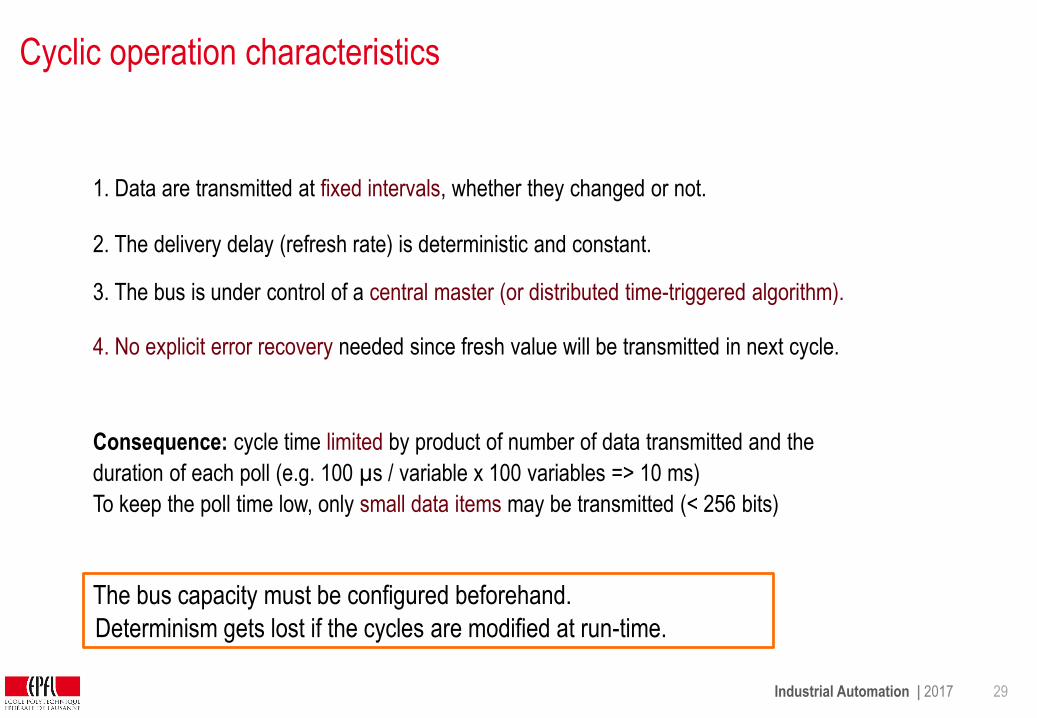
Cyclic operation characteristics
2. The delivery delay (refresh rate) is deterministic and constant.
4. No explicit error recovery needed since fresh value will be transmitted in next cycle.
To keep the poll time low, only small data items may be transmitted (< 256 bits)
3. The bus is under control of a central master (or distributed time-triggered algorithm).
1. Data are transmitted at fixed intervals, whether they changed or not.
Consequence: cycle time limited by product of number of data transmitted and the
duration of each poll (e.g. 100 µs / variable x 100 variables => 10 ms)
The bus capacity must be configured beforehand.
Determinism gets lost if the cycles are modified at run-time.

Industrial Automation | 2017 30
Optimizing Cyclic Operation
Problem: fixed portion of the bus' time used
=> poll period increases with number of polled items
=> response time slows down
Solution: introduce sub-cycles for less urgent periodic variables
length: power of 2 multiple of the base period.
Notes: Poll cycles should not be modified at run-time (non-determinism)
group with
period 1 ms
time
4a 8 16 1 4b 643
1 ms period(basic period)
2 ms period
2 4a
4 ms period
1 ms 1 ms
1 11 2

Industrial Automation | 2017 31
Cyclic Transmission with Decoupled Application
The bus master scans the identifiers at its own pace. The bus traffic and the application cycles are asynchronous to each other.
TrafficMemory
cyclic algorithms
cyclic algorithms
cyclic algorithms
cyclic algorithms
port address
application1
Ports Ports Ports
application2
application4
sourceport
sinkport
port data
sinkport
cyclic poll
bus controller
busmaster
application3
bus
PeriodicList
Ports
bus controller
bus controller
bus controller
bus controller
Deterministic behavior, at expense of reduced bandwidth and geographical extension.
Industrial Automation | 2017 32
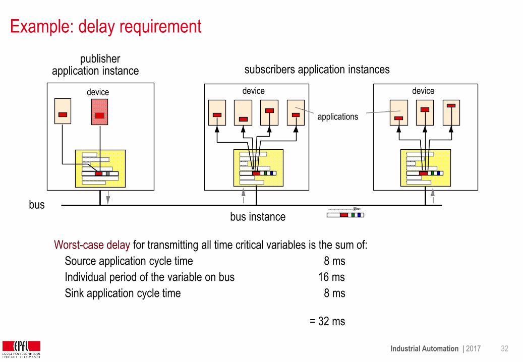
Example: delay requirement
Worst-case delay for transmitting all time critical variables is the sum of:
Source application cycle time
Individual period of the variable on bus
Sink application cycle time
8 ms
16 ms
8 ms
= 32 ms
subscribers application instances
device
publisherapplication instance
bus instance
device device
applications
bus

Industrial Automation | 2017 33
Event-driven Operation
Detection of an event is an intelligent process:
• Not every change of a variable is an event, even for binary variables.
• Often, a combination of changes builds an event.
• Only the application can decide what is an event, since only the application
programmer knows the meaning of the variables.
Events cause transmission only when state changes.
Bus load very low on average, but peaks under exceptional situations since transmissions are correlated by process (christmas-tree effect).
•
•
event-reporting
station
event-reporting
station
event-reporting
station
plant
intelligentstations
sensors/actors
Industrial Automation | 2017 34
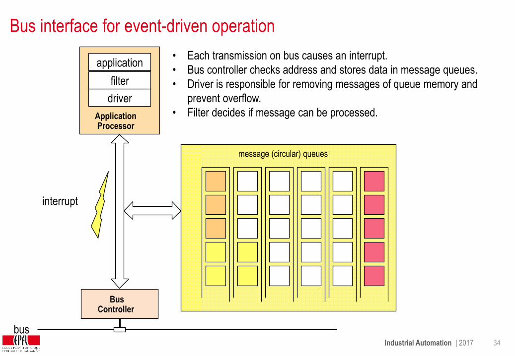
Bus interface for event-driven operation
ApplicationProcessor
Bus Controller
message (circular) queues
bus
driver
filter
application• Each transmission on bus causes an interrupt.
• Bus controller checks address and stores data in message queues.
• Driver is responsible for removing messages of queue memory and
prevent overflow.
• Filter decides if message can be processed.
interrupt
Industrial Automation | 2017 35
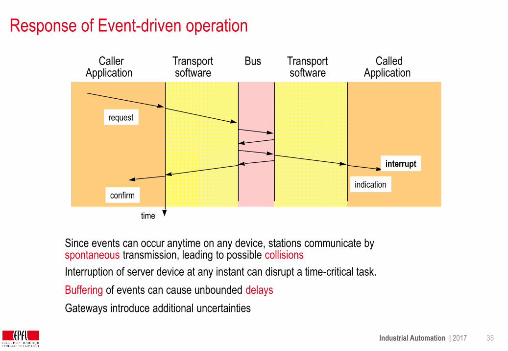
Response of Event-driven operation
Interruption of server device at any instant can disrupt a time-critical task.
Buffering of events can cause unbounded delays
Gateways introduce additional uncertainties
Since events can occur anytime on any device, stations communicate by spontaneous transmission, leading to possible collisions
CallerApplication
CalledApplication
Transportsoftware
Transportsoftware
interrupt
request
indication
confirm
Bus
time
Industrial Automation | 2017 36
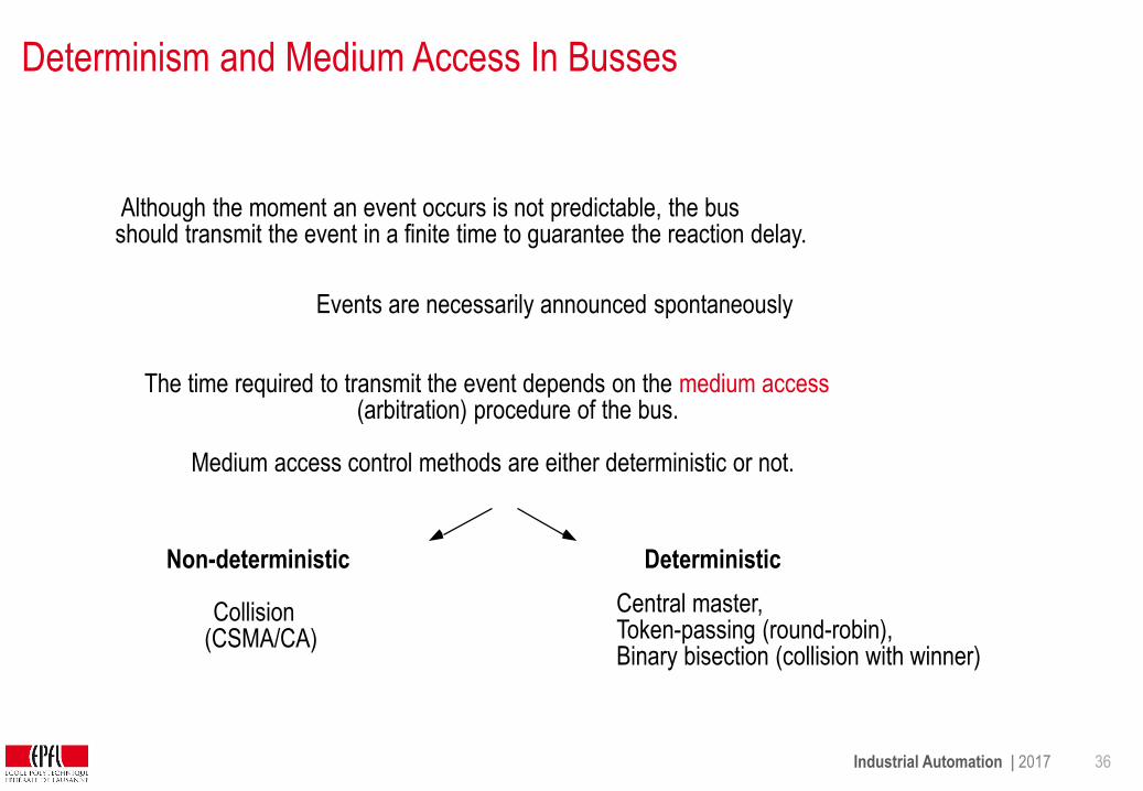
Determinism and Medium Access In Busses
Although the moment an event occurs is not predictable, the busshould transmit the event in a finite time to guarantee the reaction delay.
Events are necessarily announced spontaneously
The time required to transmit the event depends on the medium access (arbitration) procedure of the bus.
Medium access control methods are either deterministic or not.
Non-deterministic
Collision(CSMA/CA)
Deterministic
Central master,Token-passing (round-robin), Binary bisection (collision with winner)
Industrial Automation | 2017 37
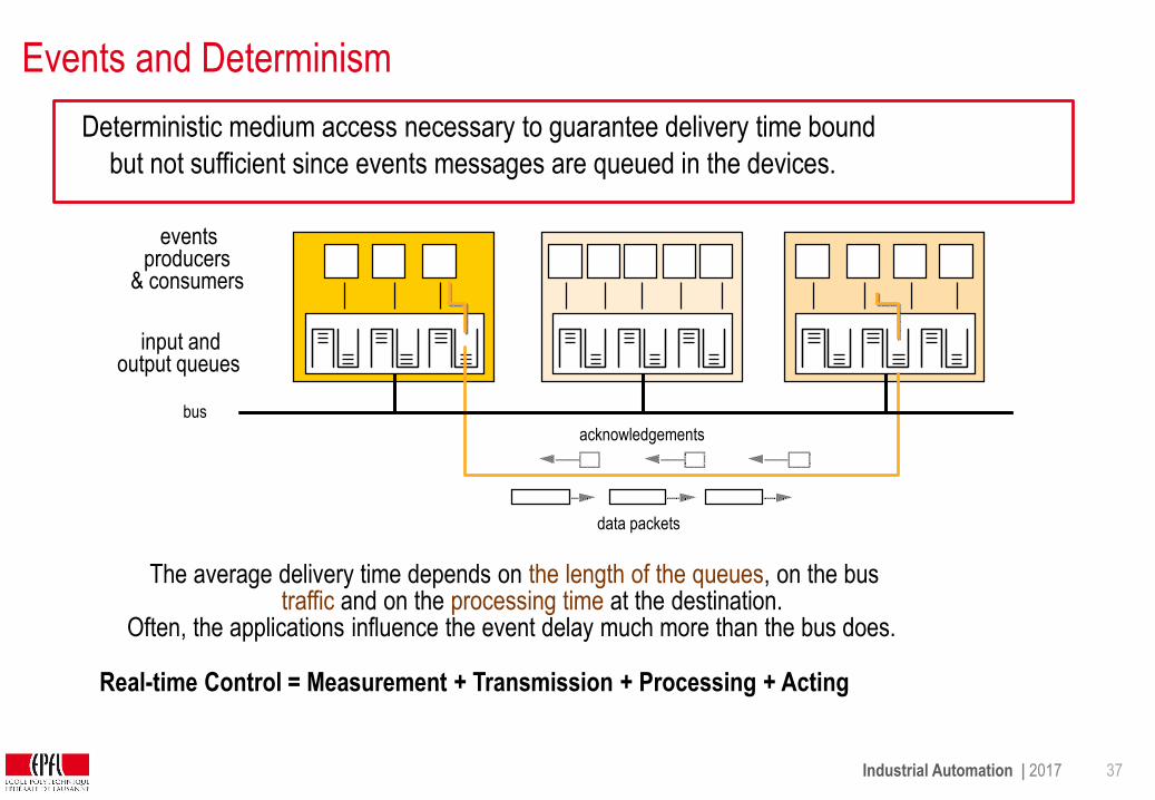
Events and Determinism
Deterministic medium access necessary to guarantee delivery time bound
but not sufficient since events messages are queued in the devices.
The average delivery time depends on the length of the queues, on the bus traffic and on the processing time at the destination.
Often, the applications influence the event delay much more than the bus does.
Real-time Control = Measurement + Transmission + Processing + Acting
bus
data packets
acknowledgements
input and output queues
events producers
& consumers
Industrial Automation | 2017 38
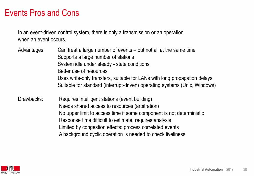
Events Pros and Cons
In an event-driven control system, there is only a transmission or an operation
when an event occurs.
Advantages:
Drawbacks:
Can treat a large number of events – but not all at the same time
Supports a large number of stations
System idle under steady - state conditions
Better use of resources
Uses write-only transfers, suitable for LANs with long propagation delays
Suitable for standard (interrupt-driven) operating systems (Unix, Windows)
Requires intelligent stations (event building)
Needs shared access to resources (arbitration)
No upper limit to access time if some component is not deterministic
Response time difficult to estimate, requires analysis
Limited by congestion effects: process correlated events
A background cyclic operation is needed to check liveliness

Industrial Automation | 2017 39
Summary: Cyclic vs Event-Driven Operation
sending: application writes data into memory
receiving: application reads data from memory
the bus controller decides when to transmit
bus and application are not synchronized
application
processor
bus
controller
traffic
memory
(buffer)
decoupled (asynchronous):
sending: application inserts data into queue
and triggers transmission,
bus controller fetches data from queue
receiving: bus controller inserts data into queue
and interrupts application to fetch them,
application retrieves data
application
processor
bus
controller
queues
coupled (with interrupts):
events
(interrupts)
Industrial Automation | 2017 40
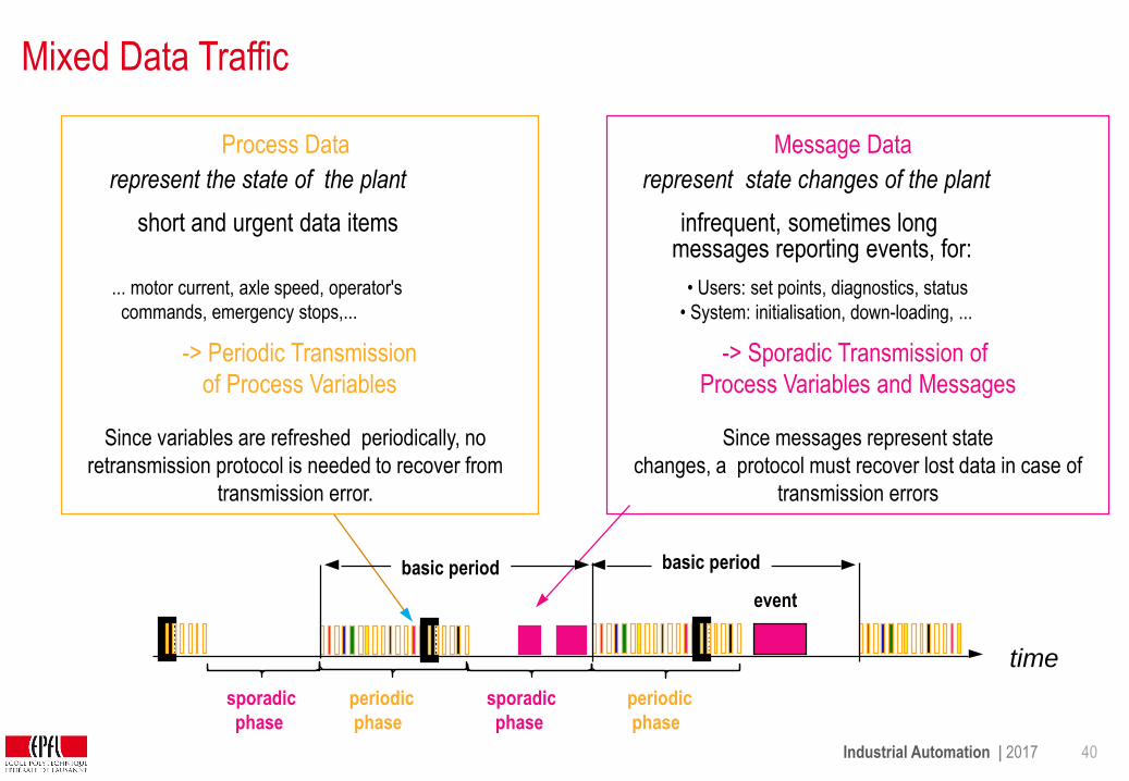
Mixed Data Traffic
represent the state of the plant represent state changes of the plant
-> Periodic Transmission
of Process Variables
short and urgent data items
Since variables are refreshed periodically, no
retransmission protocol is needed to recover from
transmission error.
-> Sporadic Transmission of
Process Variables and Messages
infrequent, sometimes longmessages reporting events, for:
• System: initialisation, down-loading, ...
Since messages represent state
changes, a protocol must recover lost data in case of
transmission errors
• Users: set points, diagnostics, status
Process Data Message Data
... motor current, axle speed, operator's
commands, emergency stops,...
periodic
phase
periodic
phase
event
sporadic
phase
time
basic period basic period
sporadic
phase
Industrial Automation | 2017 41
Mixing Traffic is a configuration issue
Cyclic broadcast of source-addressed variables standard solution for process control.
Cyclic transmission takes large share of bus bandwidth and should be reserved for really critical
variables.
Decision to declare a variable as cyclic or event-driven can be taken late in a
project, but cannot be changed on-the-fly in an operating device.
Message transmission scheme must exist alongside the cyclic transmission to carry
not-critical variables and long messages such as diagnostics or network management
An industrial communication system should provide both transmission modes.
Industrial Automation | 2017 42
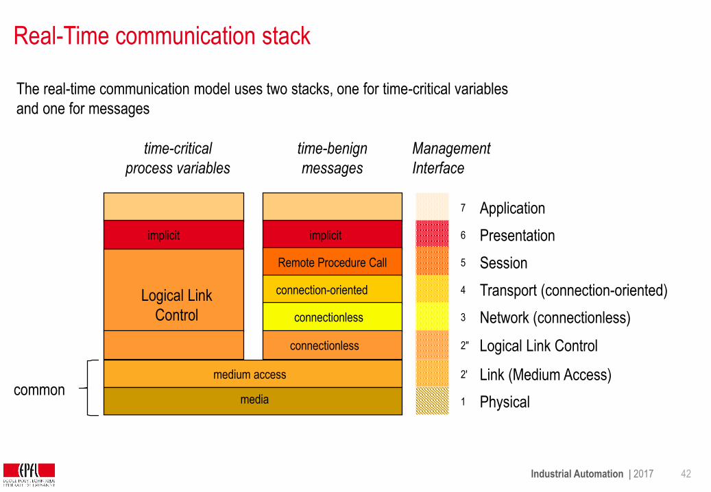
Real-Time communication stack
The real-time communication model uses two stacks, one for time-critical variables
and one for messages
Logical Link
Control
time-critical
process variables
Management
Interface
time-benign
messages
Physical
Link (Medium Access)
Network (connectionless)
Transport (connection-oriented)
Session
Presentation
Application7
6
Remote Procedure Call 5
4
3
2'
1
connectionless
connectionless
connection-oriented
medium access
implicitimplicit
Logical Link Control2"
mediacommon
Industrial Automation | 2017 43
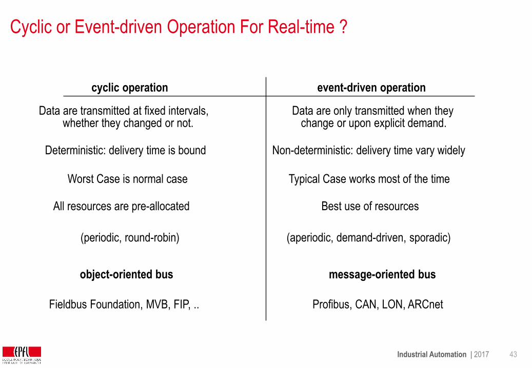
Cyclic or Event-driven Operation For Real-time ?
Data are transmitted at fixed intervals, whether they changed or not.
Data are only transmitted when they change or upon explicit demand.
cyclic operation event-driven operation
(aperiodic, demand-driven, sporadic)(periodic, round-robin)
Worst Case is normal case Typical Case works most of the time
Non-deterministic: delivery time vary widelyDeterministic: delivery time is bound
All resources are pre-allocated Best use of resources
message-oriented busobject-oriented bus
Fieldbus Foundation, MVB, FIP, .. Profibus, CAN, LON, ARCnet
Industrial Automation | 2017 44
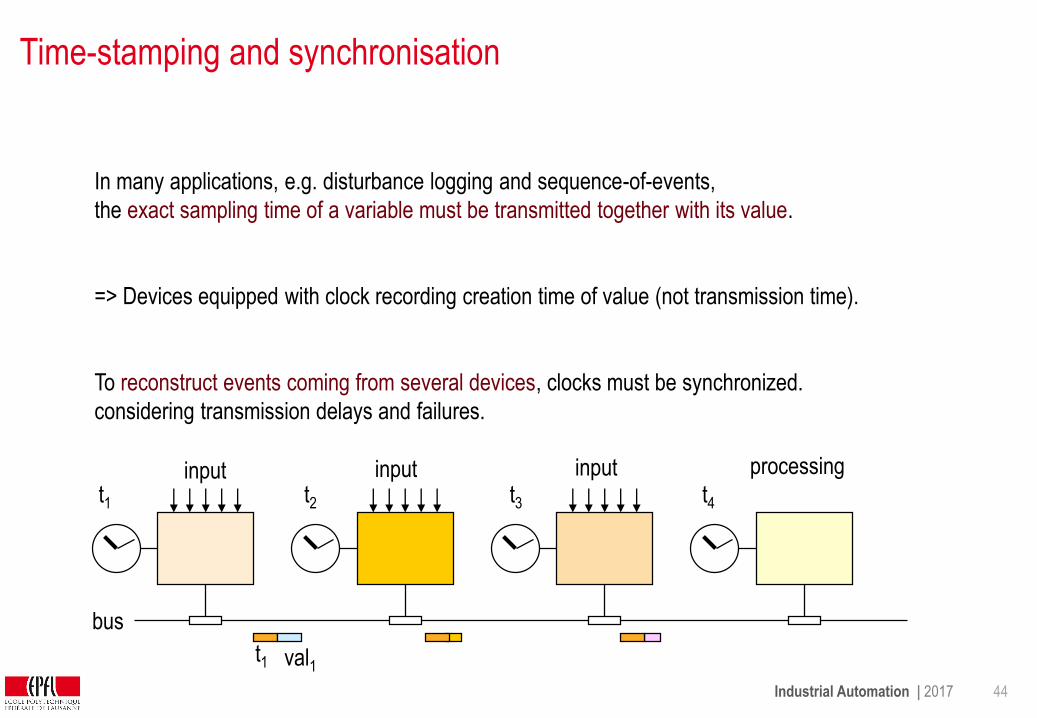
Time-stamping and synchronisation
In many applications, e.g. disturbance logging and sequence-of-events,
the exact sampling time of a variable must be transmitted together with its value.
=> Devices equipped with clock recording creation time of value (not transmission time).
To reconstruct events coming from several devices, clocks must be synchronized.
considering transmission delays and failures.
bus
input input input processing
t1 t2 t3 t4
t1 val1
Industrial Automation | 2017 45
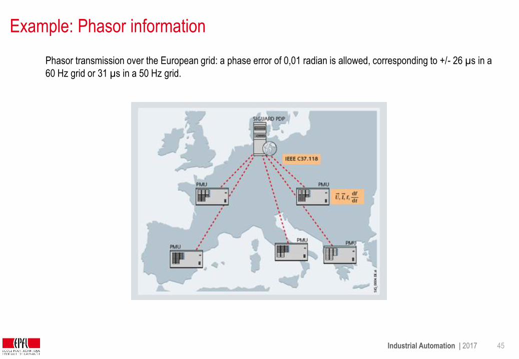
Example: Phasor information
Phasor transmission over the European grid: a phase error of 0,01 radian is allowed, corresponding to +/- 26 µs in a
60 Hz grid or 31 µs in a 50 Hz grid.
Industrial Automation | 2017 46
Time distribution
In master-slave busses, master distributes time as bus frame.
Slave can compensate for path delays, time is relative to master
In demanding systems, time is distributed over separate lines as relative time, e.g. PPS = one pulse
per second, or absolute time (IRIG-B), with accuracy of 1 µs.
In data networks, a reference clock (e.g. GPS or atomic clock) distributes the time. A protocol
evaluates the path delays to compensate them.
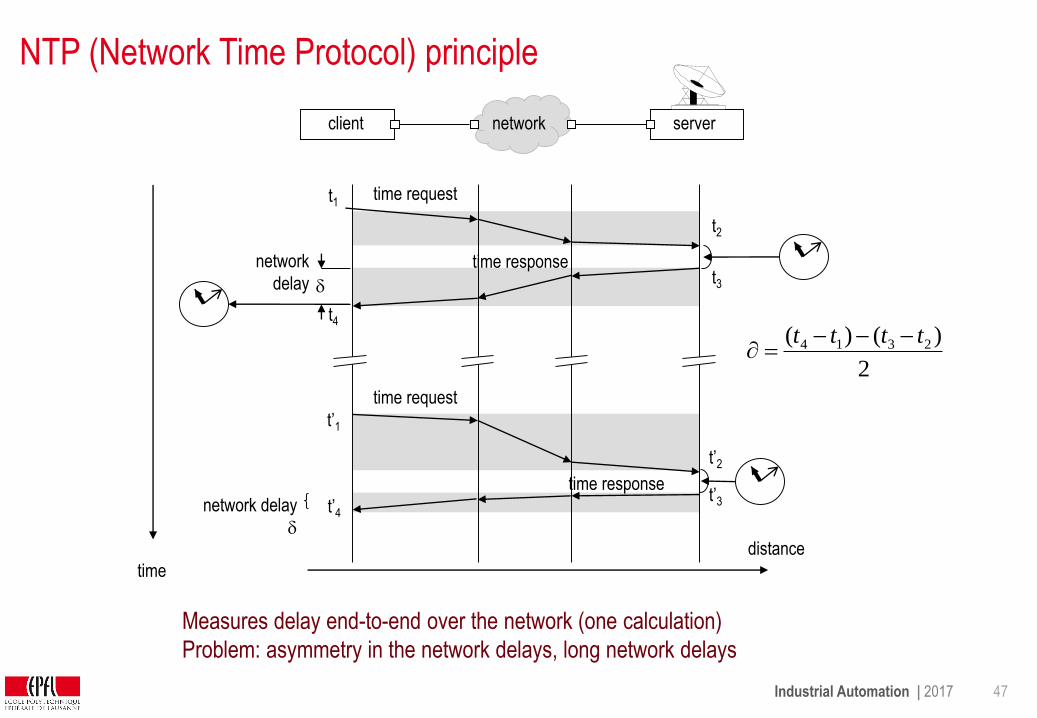
• NTP (Network Time Protocol): about 1 ms is usually achieved.
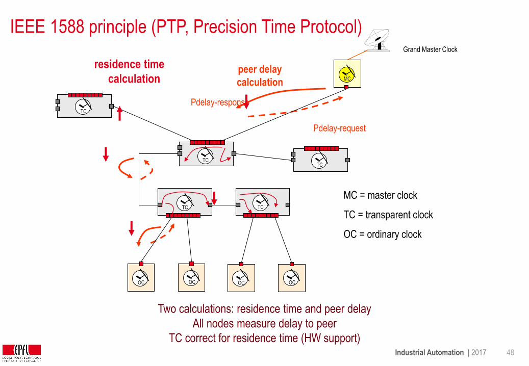
• PTP (Precision Time Protocol, IEEE 1588), all network devices collaborate to estimate the
delays, an accuracy below 1 µs can be achieved without need for separate cables (but hardware
support for time stamping required).
(Telecom networks typically do not distribute time, they only distribute frequency)
Industrial Automation | 2017 47
NTP (Network Time Protocol) principle
2
)()( 2314 tttt
time request
time response
t1
t2
t3
t4
time request
time response
t’1
t’2
t’3t’4
distance
time
network
delay
servernetworkclient
network delay
Measures delay end-to-end over the network (one calculation)
Problem: asymmetry in the network delays, long network delays
Industrial Automation | 2017 48
IEEE 1588 principle (PTP, Precision Time Protocol)Grand Master Clock
Pdelay-request
Pdelay-response
TC
TC TC
OC OC
MC
TC
OC OC
residence time
calculationpeer delay
calculation
TC
MC = master clock
TC = transparent clock
OC = ordinary clock
Two calculations: residence time and peer delay
All nodes measure delay to peer
TC correct for residence time (HW support)

Industrial Automation | 2017 49
IEEE 1588 – 1 step clocks
Sync
(contains all + )
residence
time
Pdelay_Resp
(contains t3 – t2)
Pdelay_Req
ordinary
(slave) clock
distance
time
Sync
1-step
transparent
clock
grand
master clock
1-step
transparent
clock
residence
time
bridge bridge
link delay t2
t3
Pdelay_Resp
t1
t4
Pdelay_Reqt2
t3
t1
t4
t2
t3
t1
t4
Sync
Pdelay_Resp
Pdelay_Req
t5
t5
t6
Grandmaster sends the time spontaneously.
Each device computes the path delay to its neighbour and its residence time
and corrects the time message before forwarding it
residence time
calculation
peer delay
calculation

Industrial Automation | 2017 50
References
To probe further
• http://www.ines.zhaw.ch/fileadmin/user_upload/engineering/_Institute_und_Zentren/INES/IEEE158
8/Dokumente/IEEE_1588_Tutorial_engl_250705.pdf
• http://blog.meinbergglobal.com/2013/11/22/ntp-vs-ptp-network-timing-smackdown/
• http://blog.meinbergglobal.com/2013/09/14/ieee-1588-accurate/

Industrial Automation | 2017 51
Networking field busses
Networking field busses is not done through bridges or routers,
because normally, transition from one bus to another is associated with:
- data reduction (processing, sum building, alarm building, multiplexing)
- data marshalling (different position in the frames)
- data transformation (different formats on different busses)
Only system management messages could be threaded through from end to end,
but due to lack of standardization, data conversion is not avoidable today.
Industrial Automation | 2017 52
Assessment
What is the difference between a centralized and a decentralized industrial
bus ?
What is the principle of source-addressed broadcast ?
What is the difference between a time-stamp and a freshness counter ?
Why is an associative memory used for source-addressed broadcast ?
What are the advantages / disadvantages of event-driven communication ?
What are the advantages / disadvantages of cyclic communication ?
How is time transmitted ?
How are field busses networked ?
Industrial Automation | 2017 53
3 Industrial Communication Networks
3.1 Field bus principles
3.2 Field bus operation
3.3 Standard field busses
3.4 Industrial wireless communication
Industrial Automation | 2017 54
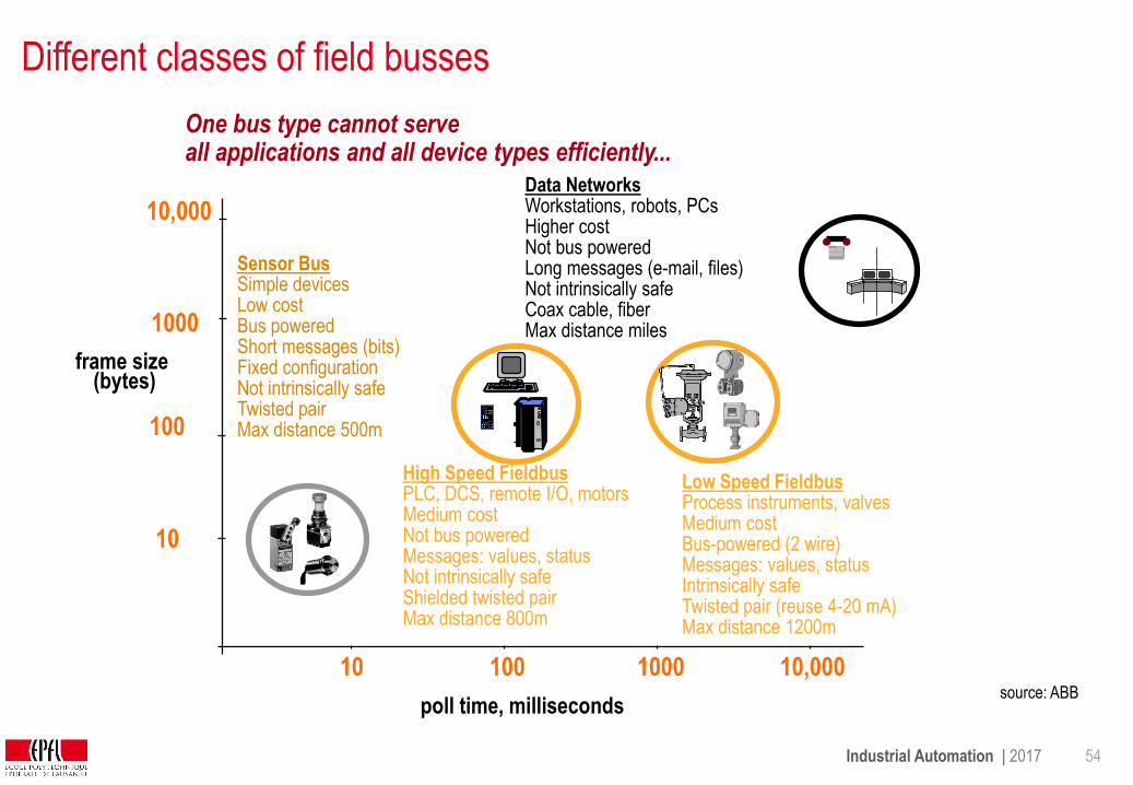
Different classes of field busses
poll time, milliseconds
10
100
1000
10,000
10 100 1000 10,000
Sensor BusSimple devicesLow costBus powered Short messages (bits)Fixed configuration Not intrinsically safeTwisted pairMax distance 500m
Low Speed FieldbusProcess instruments, valvesMedium costBus-powered (2 wire)Messages: values, statusIntrinsically safeTwisted pair (reuse 4-20 mA)Max distance 1200m
High Speed FieldbusPLC, DCS, remote I/O, motorsMedium costNot bus poweredMessages: values, statusNot intrinsically safeShielded twisted pairMax distance 800m
Data NetworksWorkstations, robots, PCsHigher costNot bus powered Long messages (e-mail, files)Not intrinsically safeCoax cable, fiberMax distance miles
PV 6000
SP 6000
Honeywell
AUTO
1
One bus type cannot serveall applications and all device types efficiently...
source: ABB
frame size(bytes)

Industrial Automation | 2017 55
Worldwide most popular field busses
Market shares held by the leading fieldbus and industrial Ethernet systems
Source: HMS Industrial Networks, 2016

Industrial Automation | 2017 56
Field device: example differential pressure transducer
The device transmits its value by means of a current loop
4..20 mA current loop
fluid

Industrial Automation | 2017 57
4-20 mA loop - the conventional, analog standard
The transducer limits the current to a value between 4 mA and 20 mA,
proportional to the measured value, while 0 mA signals an error (wire break)
The voltage drop along the cable and the number of readers induces no error.
Simple devices are powered directly by the residual current (4mA), allowing to transmit signal and power
through a single pair of wires.
4-20mA is basically a point-to-multipoint communication (one source)
The 4-20 mA is the most common analog transmission standard in industry
transducer reader1
reader2
i(t) = 0, 4..20 mA
R1 R2 R3
sensor
i(t) = f(v)
voltage
source
10V..24V
RL4 conductor resistance
RL2 RL3 RL4RL1
flow
Industrial Automation | 2017 58
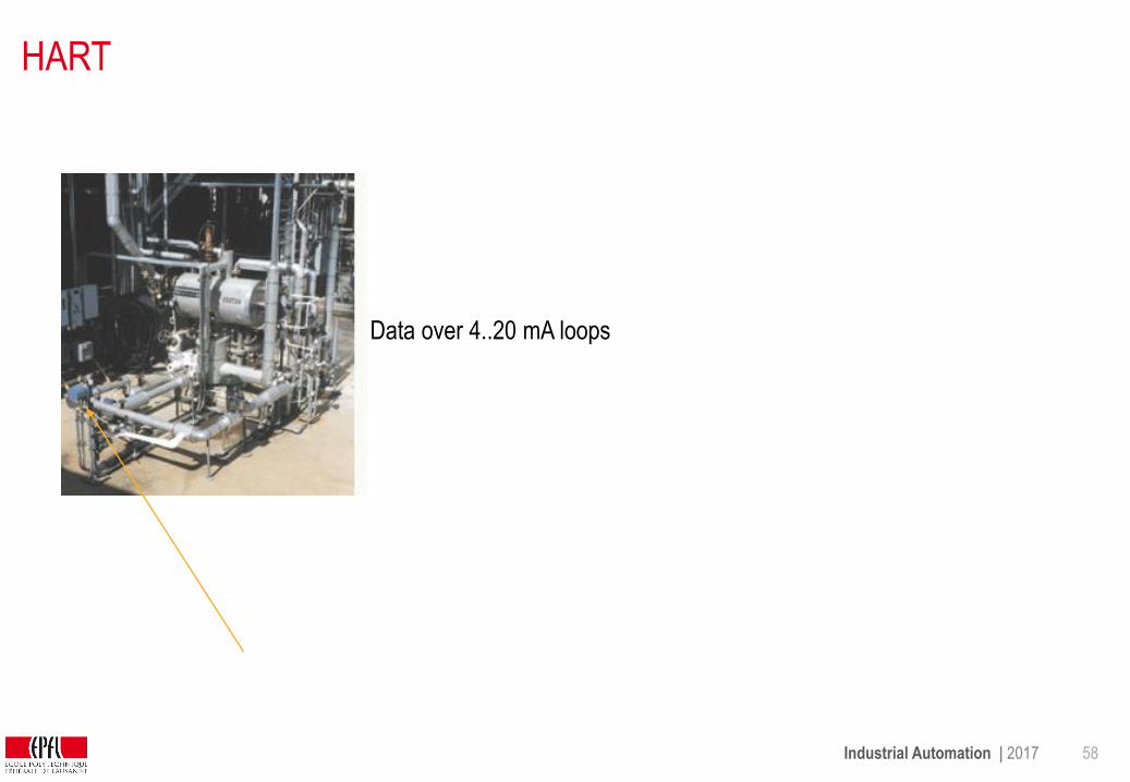
HART
Data over 4..20 mA loops

Industrial Automation | 2017 59
HART – Principle (1986)
HART (Highway Addressable Remote Transducer) was developed by Fisher-Rosemount to retrofit 4-to-20mA
current loop transducers with digital data communication (not for closed-loop communication).
HART modulates the 4-20mA current
with a low-level frequency-shift-keyed
(FSK) sine-wave signal, without
affecting the average analogue signal.
HART uses low frequencies (1200Hz
and 2200 Hz) to deal with poor
cabling, its rate is 1200 Bd - but
sufficient.
Transmission of device characteristics is normally not real-time critical
Industrial Automation | 2017 60
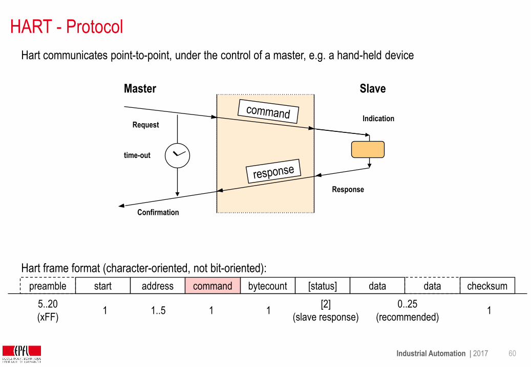
HART - Protocol
Hart communicates point-to-point, under the control of a master, e.g. a hand-held device
preamble start address command bytecount [status] data data checksum
1 1..55..20
(xFF)1 1
[2]
(slave response)
0..25
(recommended)1
Master
Indication
Slave
Request
Confirmation
Response
time-out
Hart frame format (character-oriented, not bit-oriented):

Industrial Automation | 2017 61
Universal commands (mandatory):identification,
primary measured variable and unit (floating point format)
loop current value (%) = same info as current loop
read current and up to four predefined process variables
write short polling address
sensor serial number
instrument manufacturer, model, tag, serial number, descriptor,
range limits, …
Common practice (optional)
time constants, range,
EEPROM control, diagnostics,…
total: 44 standard commands, plus user-defined commands
Transducer-specific (vendor-defined)
calibration data,
trimming,…
HART - Commands
Industrial Automation | 2017 62
HART - Importance
Practically all 4..20mA devices come equipped with HART today
About 40 Mio devices are sold per year.
more info:
http://www.thehartbook.com/default.asp
http://www.hartcomm.org/

Industrial Automation | 2017 63
Fieldbus Comparison
Fieldbus BW Max
Length
Max
Data
Size
Application Max Nodes Notes
PROFIBUS
(DP and
PA)
1.5-12
Mbit/s
31.25
Kbits/s
100 m – 24
km
1900 m
246
bytes
Factory
Automation
Process
Automation
127
32
Token passing, master-slave /
P2P, operate sensors and
actuators (DP), monitor
measuring equipment (PA)
DeviceNet250
kBit/s500 m 8 bytes
Factory
Automation64
CSMA/CD, master-slave,
multidrop, motors, drives, uses
CAN
CANopen
10 kBit/s
-
1 Mbit/s
25-1000 m 8 bytes
Automobile,
Industrial
Automation
127CSMA, Ideal for small data and
fast sync, uses CAN
http://www.bierlemartin.de/hengstler/training/fbcomp.htm
http://www.pacontrol.com/download/fieldbuscomp.pdf
http://www.mtl.de/pdfs/news/open_fieldbus.pdf
Industrial Automation | 2017 64
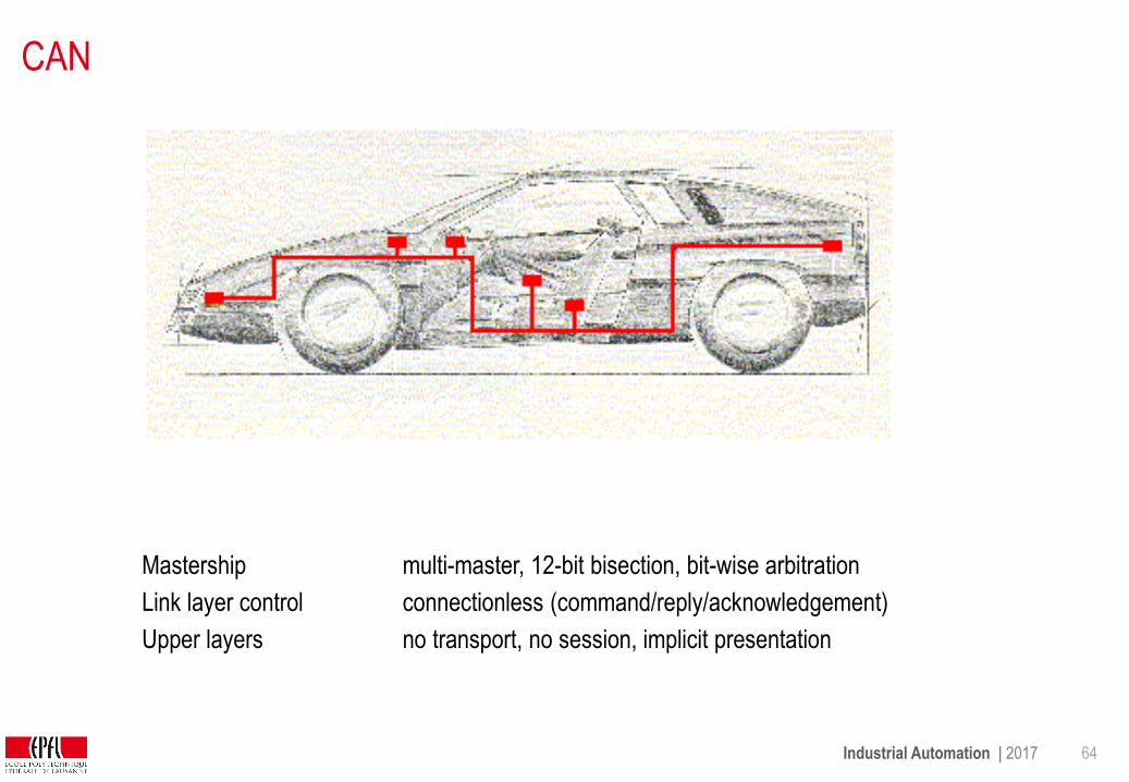
CAN
Mastership multi-master, 12-bit bisection, bit-wise arbitration
Link layer control connectionless (command/reply/acknowledgement)
Upper layers no transport, no session, implicit presentation
Industrial Automation | 2017 65
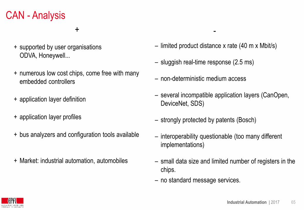
CAN - Analysis
– interoperability questionable (too many different
implementations)
– small data size and limited number of registers in the
chips.
+ application layer definition– several incompatible application layers (CanOpen,
DeviceNet, SDS)
– strongly protected by patents (Bosch)
+ supported by user organisations
ODVA, Honeywell...
+ application layer profiles
– limited product distance x rate (40 m x Mbit/s)
– sluggish real-time response (2.5 ms)
+ bus analyzers and configuration tools available
+ numerous low cost chips, come free with many
embedded controllers – non-deterministic medium access
+ Market: industrial automation, automobiles
+ -
– no standard message services.

Industrial Automation | 2017 66
Ethernet Paradigms
switch
switch
SCADA
Fieldbus
Ethernet
SCADA
simple
devices
PLC PLC PLC
Soft-PLC Soft-PLCSoft-PLCSoft-PLC
Ethernet
costlier field devices
Soft-PLC as concentrators
Event-driven operation
cheap field devices
decentralized I/O
cyclic operation
Classical Ethernet + Fieldbus
Ethernet as Fieldbus
This is a different wiring philosophy.
The bus must follow the control system structure, not the other way around
Industrial Automation | 2017 67
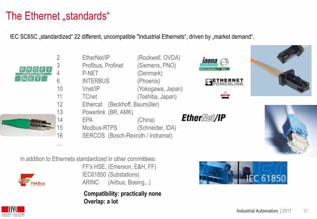
The Ethernet „standards“
IEC SC65C „standardized“ 22 different, uncompatible "Industrial Ethernets“, driven by „market demand“.
Compatibility: practically none
Overlap: a lot
2 EtherNet/IP (Rockwell. OVDA)
3 Profibus, Profinet (Siemens, PNO)
4 P-NET (Denmark)
6 INTERBUS (Phoenix)
10 Vnet/IP (Yokogawa, Japan)
11 TCnet (Toshiba, Japan)
12 Ethercat (Beckhoff, Baumüller)
13 Powerlink (BR, AMK)
14 EPA (China)
15 Modbus-RTPS (Schneider, IDA)
16 SERCOS (Bosch-Rexroth / Indramat)
…
In addition to Ethernets standardized in other committees:
FF's HSE, (Emerson, E&H, FF)
IEC61850 (Substations)
ARINC (Airbus, Boeing,..)
Industrial Automation | 2017 68
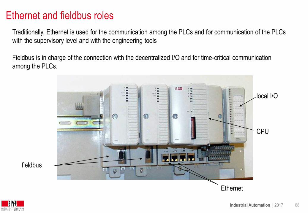
Ethernet and fieldbus roles
Traditionally, Ethernet is used for the communication among the PLCs and for communication of the PLCs
with the supervisory level and with the engineering tools
Fieldbus is in charge of the connection with the decentralized I/O and for time-critical communication
among the PLCs.
Ethernet
fieldbus
local I/O
CPU
Industrial Automation | 2017 69
Future of field busses
Non-time critical busses are being displaced by LANs (Ethernet)and cheap peripheral busses (USB, …)
These "cheap" solutions are being adapted to the industrial environmentand become a proprietary solution (e.g. Siemens "Industrial Ethernet")
The cabling objective of field busses (more than 32 devices over 400 m) is out of reach for cheap peripheral busses such as USB.
Fieldbusses tend to live very long (10-20 years), contrarily to office products.
There is no real incentive from the control system manufacturers to reduce the fieldbus diversity, since the fieldbus binds customers.
The project of a single, interoperable field bus defined by users (Fieldbus Foundation) failed, both in the standardisation and on the market.

Industrial Automation | 2017 70
Fieldbus Selection Criteria
Installed base, devices availability: processors, input/output
Interoperability (how likely is it to work with a product from another manufacturer
Topology and wiring technology (layout)
Connection costs per (input-output) point
Response time
Deterministic behavior
Device and network configuration tools
Bus monitor (baseline and application level) tools
Integration in development environment
Power distribution and galvanic separation (power over bus, potential differences)
Industrial Automation | 2017 71
Assessment
Which is the medium access and the link layer operation of CAN ?
What is the wiring philosophy of Industrial Ethernet?
Which are the selection criteria for a field bus ?
What makes a field bus suited for hard-real-time operation ?
How does the market influence the choice of the bus ?

Industrial Automation | 2017 72
3 Industrial Communication Networks
3.1 Field bus principles
3.2 Field bus operation
3.3 Standard field busses
3.4 Industrial wireless communication
Industrial Automation | 2017 73
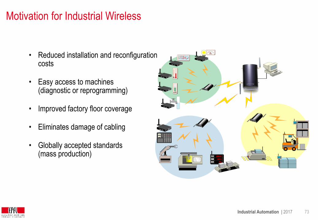
Motivation for Industrial Wireless
• Reduced installation and reconfiguration costs
• Easy access to machines (diagnostic or reprogramming)
• Improved factory floor coverage
• Eliminates damage of cabling
• Globally accepted standards(mass production)
Industrial Automation | 2017 74
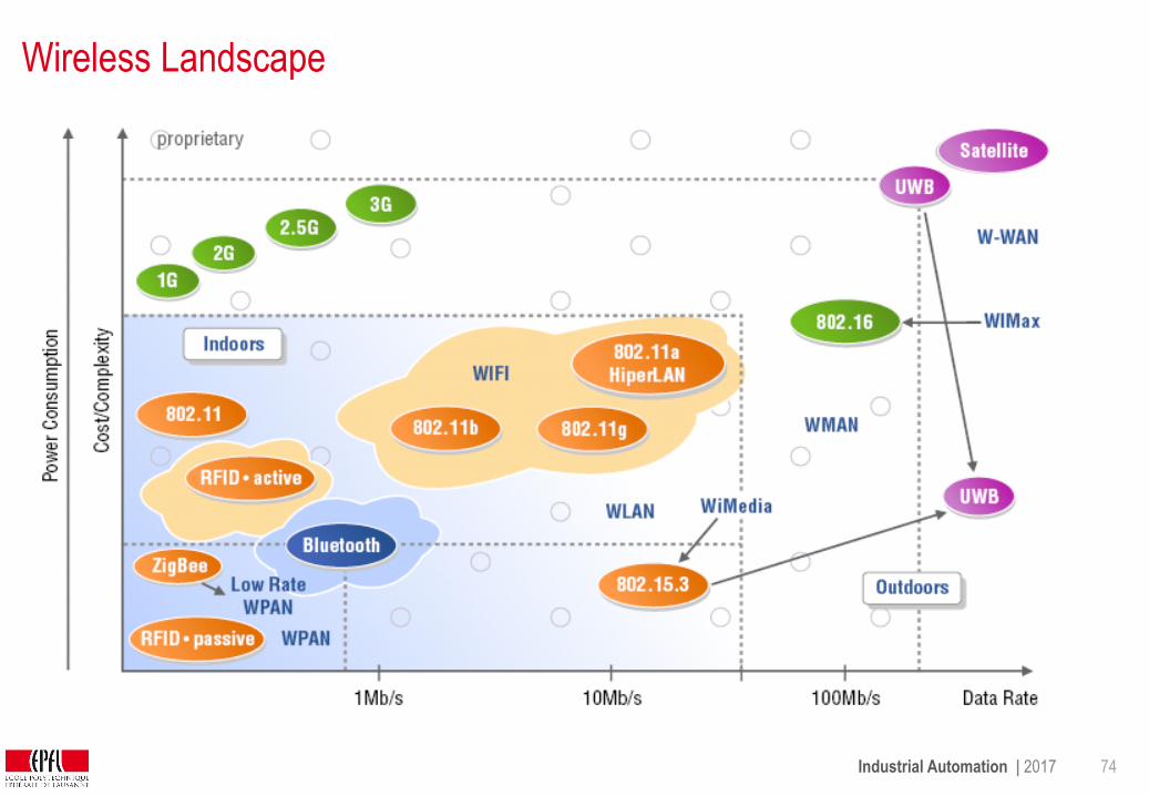
Wireless Landscape
Industrial Automation | 2017 75
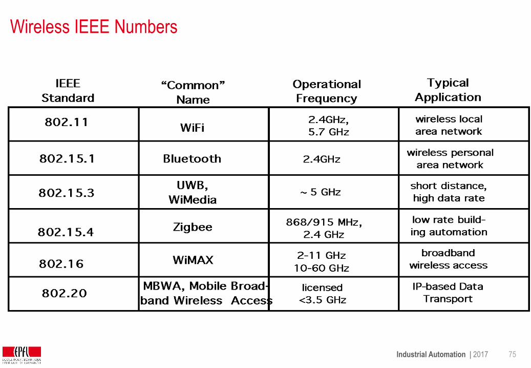
Wireless IEEE Numbers

Industrial Automation | 2017 76
Requirements for Industrial Wireless
Wireless Industrial
Applications
time
Non Real -
Hard Real -Time
Remote Control
Machine Health Monitoring
System Configuration
Internet Connectivity
Control Loops
Machine-to-machine communication
Events Registration
Measurements
Media
-R
eal
Soft
time
Industrial Automation | 2017 77
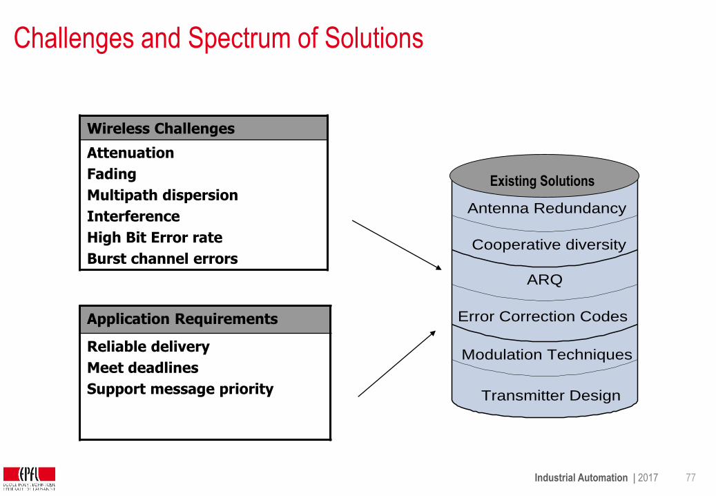
Challenges and Spectrum of Solutions
Wireless Challenges
Attenuation
Fading
Multipath dispersion
Interference
High Bit Error rate
Burst channel errors
Application Requirements
Reliable delivery
Meet deadlines
Support message priority
Antenna Redundancy
Cooperative diversity
ARQ
Error Correction Codes
Modulation Techniques
Transmitter Design
Existing SolutionsExisting Solutions
Industrial Automation | 2017 78
Reliability for wireless channel
Radio wave interferes with surrounding environment creating multiple waves at
receiver antenna, they are delayed with respect to each other. Concurrent
transmissions cause interference too.
=> Bursts of errors
Forward Error Correction (FEC):
Encoding redundancy to overcome error bursts
Automated Repeat ReQuest (ARQ):
Retransmit entire packets when receiver cannot decode the packet
(acknowledgements)
Industrial Automation | 2017 79
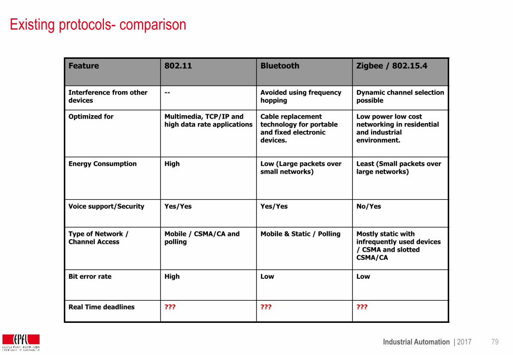
Existing protocols- comparison
Feature 802.11 Bluetooth Zigbee / 802.15.4
Interference from other devices
-- Avoided using frequency hopping
Dynamic channel selection possible
Optimized for Multimedia, TCP/IP and high data rate applications
Cable replacement technology for portable and fixed electronic devices.
Low power low cost networking in residential and industrial environment.
Energy Consumption High Low (Large packets over small networks)
Least (Small packets over large networks)
Voice support/Security Yes/Yes Yes/Yes No/Yes
Type of Network / Channel Access
Mobile / CSMA/CA and polling
Mobile & Static / Polling Mostly static with infrequently used devices / CSMA and slotted CSMA/CA
Bit error rate High Low Low
Real Time deadlines ??? ??? ???
Industrial Automation | 2017 80
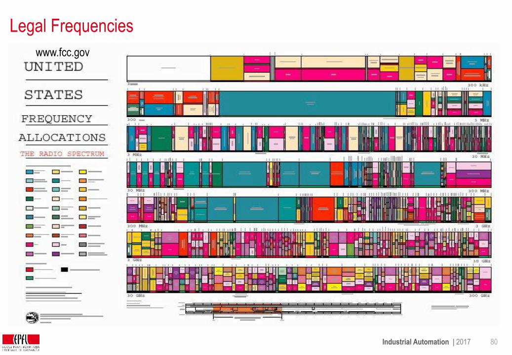
Legal Frequencies
www.fcc.gov
Industrial Automation | 2017 81
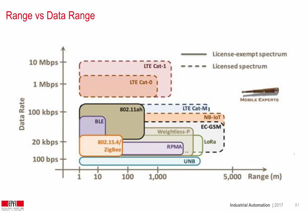
Range vs Data Range
1 m
10 m
100 m
1 km
10 km
0 GHz 2 GHz1GHz 3 GHz 5 GHz4 GHz 6 GHz
802.11a
UWB
ZigBee BluetoothZigBee
802.11b,g
3G
UWB

Industrial Automation | 2017 82
Industrial Example: WirelessHART
HART (Highway Addressable Remote Transducer) fieldbus protocol
Supported by 200+ global companies
Since 2007 Compatible WirelessHART extension

Industrial Automation | 2017 83
WirelessHART Networking Stack
PHY:
• 2,4 GHz Industrial, Scientific, and Medical Band (ISM-Band)
• Transmission power 0 - 10 dBm
• 250 kbit/s data rate
MAC:
• TDMA (10ms slots, static roles)
• Collision and interference avoidance:
Channel hopping and black lists
Network layer:
• Routing (graph/source routing)
• Redundant paths
Industrial Automation | 2017 84
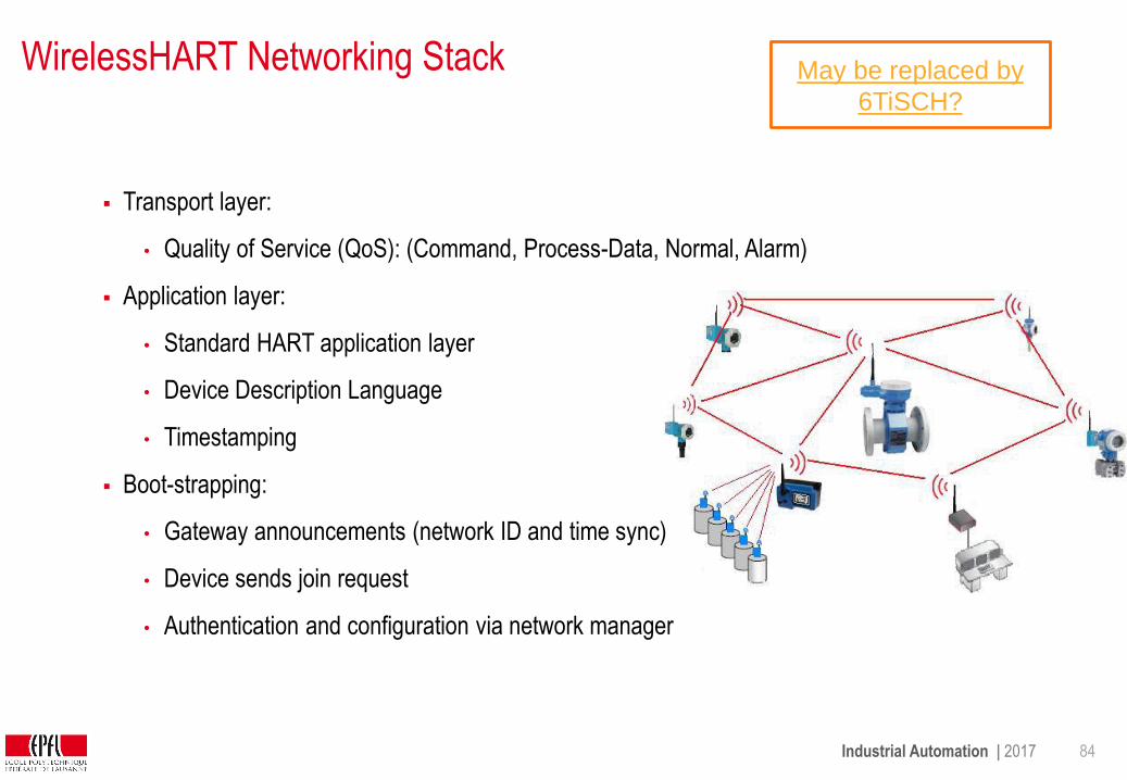
WirelessHART Networking Stack
Transport layer:
• Quality of Service (QoS): (Command, Process-Data, Normal, Alarm)
Application layer:
• Standard HART application layer
• Device Description Language
• Timestamping
Boot-strapping:
• Gateway announcements (network ID and time sync)
• Device sends join request
• Authentication and configuration via network manager
May be replaced by
6TiSCH?

Industrial Automation | 2017 85
Design Industrial Wireless Network
Existing wireless in plant; frequencies used?
Can the new system co-exist with existing?
How close are you to potential interferences?
What are uptime and availability requirements?
Can system handle multiple hardware failures without
performance degradation?
What about energy source for wireless devices?
Require deterministic power consumption to ensure predictable
maintenance.
Power management fitting alerting requirements and battery
replacement goals

Industrial Automation | 2017 86
Assessment
• Why is a different wireless system deployed in a factory than at home?
• What are the challenges of the wireless medium and how are they tackled?
• How can UWB offer both a costly and high bandwidth and a cheaper and high
bandwidth services?
• Which methods are used to cope with the crowded ISM band?
• Why do we need bootstrapping in Wireless HART?
Industrial Automation | 2017 87
References
• Wireless Communication in Industrial Networks, Kavitha Balasubramanian, Cpre 458/558: Real-Time
Systems, www.class.ee.iastate.edu/cpre458/cpre558.F00/notes/rt-lan7.ppt
• WirelessHART, Christian Hildebrand, www.tu-cottbus.de/systeme,
http://systems.ihp-microelectronics.com/uploads/downloads/
2008_Seminar_EDS_Hildebrand.pdf
• WirelessHARTTM Expanding the Possibilities, Wally Pratt HART Communication Foundation,
www.isa.org/wsummit/.../RHelsonISA-Wireless-Summit-7-23-07.ppt
• Industrial Wireless Systems, Peter Fuhr, ISA,
www.isa.org/Presentations_EXPO06/FUHR_IndustrialWirelessPresentation_EXPO06.ppt


![EPFL - Information Calcul et Communication : [5pt] Présentation … · 2019-09-13 · c EPFL 2019-20 Jamila Sam & Jean-Cédric Chappelier Information Calcul et Communication : Présentation](https://img.dokumen.tips/doc/110x75/5fb1a8e7b9f5c2602f5f8fdc/epfl-information-calcul-et-communication-5pt-prsentation-2019-09-13-c.jpg)


