Embed Size (px)
Citation preview

Eos,Vol. 81, No. 15,April 11, 2000
EOS VOLUME 81 NUMBER 15
APRIL 11, 2000
PAGES 157-168
Hawaii-2 Observatory Pioneers Opportunities for Remote Instrumentation in Ocean Studies PAGES 157,162-163
Beneath 5000 m of water midway between Hawaii and California, the Hawaii-2 Observatory (H20) rests on the seafloor (Figure 1). Telemetry and power come to this pioneer, deep-ocean scientific observatory via a retired telephone cable, Hawaii-2, donated by AT&T to the Incorporated Research Institutions for Seismology (IRIS) Consortium for the benefit of the scientific community. H20 is the first Global Seismographic Network (GSN) station on the seafloor.With a suite of wet-mateable connectors on a junction box (j-box), H20 offers marine scientists a new opportunity to deploy and operate remote instrumentation in the middle of the ocean.
H 2 0 to Provide Much Needed Data
Although the Earth is mostly covered by ocean, nearly all of the long-term geophysical time series have been collected on land.The near absence of long-term geophysical data from the seafloor starkly contrasts with the century-long record of land-based seismic and geomagnetic observations. Deployment of instrumentation in the ocean and on and below the seafloor has been limited by the availability of ships, battery capacity, corrosion problems, and data storage technology.The reuse of retired undersea telephone cables brings electrical power to the seafloor, allowing the scientific community to install equipment for long-term studies and communicate with the instruments in real-time.
The scientific driver for H20 was primarily seismology, but there are new opportunities for geomagnetism, tsunami studies, biology, and physical oceanography, among other fields. Seismology's need for good global coverage has been the impetus for the IRIS Global Seismographic Network (GSN). Many GSN stations are sited on islands. However, islands are not generally representative samples of the oceans, and vast areas of the oceans are without islands.The Hawaii-2 Observatory fills one of these important gaps in the northeast Pacific and will provide much needed control
in studies of earthquake sources in Hawaii, the western United States, and Alaska.
Furthermore,since the data are recorded in real-time on Oahu island via the Hawaii-2 cable and made immediately available to the seismo-logical community via the IRIS Data Management System, data from H20 can be incorporated into epicenter and focal mechanism determinations made within tens of minutes following an earthquake. Figure 2 shows H20 seismic data from a California earthquake.Tsunamis generated by large earthquakes with epicenters from the Gulf of Alaska to Central America will be recorded at H20 within 30 minutes to 2 hours prior to their arrival in the Hawaiian Islands.The H20 data may eventually be incorporated with operational data for the tsunami warning networks.
The structure of the Earths mantle can be strongly constrained by studies of seismic waveforms. Seismic rays turning and reflecting in the upper mantle illuminate and constrain the mantle structure. Located between the seismicity in
California and Hawaii, the H20 site will yield the first direct evidence of the nature and variability of the 40Okm discontinuity beneath the northeastern Pacific. Furthermore, the extensive seismicity in the western United States will provide coverage of deeper structure in the upper mantle as well.The data from H20 will enhance existing data sets of multiple reflected body waves such as ScSn,SS,SSS,PcPetc,which sample the Earth between earthquake source and receiver, by broadening GSN coverage with unique, new paths and reflection bounce points. Finally the observation of shear-wave splitting at H20 will be diagnostic of anisotropy in the mantle beneath the site. Seismic data from H20 will enhance our understanding of elastic and anelas-tic structure and anisotropy in the lithosphere and asthenosphere of the northeast Pacific.
High-frequency Po and So waves, which propagate in the older, western Pacific lithosphere but heretofore have not been observed in the younger, northeast Pacific, may be observable at H20 from Hawaii and California earthquakes. Analyses of long-period (>15 s) surface waves recorded at H20 will yield true, pure-path oceanic data for studies and will afford a perspective of the wave propagation without the complications of ocean-continent boundary effects or island effects that have implicitly been a part of all previous studies. In global surface-wave tomo-
Oahu
Fig. 1. (Left) The Hawaii-2 Observatory at 27° 52.916'N, 141° 59.504'Wis sited 1750 km east-northeast of Honolulu. The site lies between the Murray and Molokai Fracture Zones at 4979 m depth on about 100 m of predominantly terrigeneous, pelagic clay. The oceanic crust is of Eocene age (45-50 m.y.) and is normal but fast spreading with a spreading half-rate of 7 cm/y. (Center) The path of the Hawaii-2 Cable runs between Oahu and Kauai, then heads northeast toward California. (Right) The AT&T Makaha Cable Station on western Oahu is connected via a leased 256 KB/s Frame Relay circuit to the University of Hawaii for data transmission to a data collection center and the Internet. Original color image appears at the back of this volume.
E O S , T R A N S A C T I O N S , A M E R I C A N G E O P H Y S I C A L U N I O N

Eos,Vol.81,No. 15,April 11,2000
E <
48 50 52 54 56 58 60 62 64 66 68
Minutes After 0900Z, October 16, 1999
Fig. 2. The magnitude 7.0 Hector Mine earthquake on October 16,1999, in southern California recorded at the H20 site at 2550 km distance. Two orthogonal horizontal and the vertical (Z) components are shown, low-pass filtered at 0.2 Hz. Fortuitously, the HI component is aligned nearly radially along the great circle from the earthquake, showing the compressional body waves and Raleigh wave similar to the vertical. The transverse H2 component shows shear waves and the Love wave. Original color image appears at the back of this volume.
graphic studies, the H20 site will substantially enhance the coverage of the eastern Pacific.
For geomagnetism and other marine sciences, the H20 site offers a new platform for making long-term scientific measurements in a deep-ocean setting without constraints imposed by low-power, internal recording, and temporary deployments.The H20 site also extends to geomagnetism the opportunity to improve the global geographic distribution of geomagnetic observatories.
Second Life for Used Phone Cables
In 1987 Shozaburo Nagumo of the University of Tokyo approached IRIS to collaborate on reusing the Trans-Pacific Cable-1 (TPC-1) that was soon to be retired from telephone service as newer fiber-optic cables came online [Nagumo etal, 1981].In 1991,recognizing the opportunity for permanent stations on the seafloor, a section of TPC-1 from Guam to Japan was transferred from AT&T and the Kokusai Denshin Denwa Co., Ltd. in Japan to IRIS and the University of Tokyo. With National Science Foundation (NSF) funding to IRIS for the work at the cable terminus on Guam in 1992, the Japanese spliced a short-period seismic package into TPC-1 300 km south of Tokyo in 1996 [U.S. Cable Steering Committee, 1992; Kasahara et al, 1998].
The success and experience of reusing TPC-1 led U.S. efforts to focus on the Hawaii-2 cable (Figure 1) as the best deep-ocean location for improving global coverage and providing for regional studies near the United States.Three enhancements were sought and achieved in reusing Hawaii-2:
• a conventional, large oceanographic vessel was used instead of a specialized, commercial cable ship,
• a j-box connected to the cable with underwater wet-mateable connectors allowed users to add and change scientific instruments, and
• a broadband seismometer was buried beneath the seafloor to meet GSN standards.With the donation of the Hawaii-2 Cable, IRIS obtained NSF funding for the H20 project in 1995.
The Hawaii-2 Observatory was installed in September 1998, and was revisited for maintenance and repair in September 1999 by the R/V Thomas G. Thompson and the remotely operated vehicle (ROV) Jason.
The Hawaii-2 submarine telephone cable system (HAW-2) uses vacuum tube Submarine-D (SD) cable technology which was developed by AT&T around 1960.This second-generation seafloor telecommunications system is also used in TPC-1 and numerous other civilian and military cables around the world.The deep-water SD cable is an armorless coaxial cable, about 3 cm in diameter, with an internal strength member. Power is supplied (about 3300 V with a constant system current of 370 mA) to the cable center conductor from the Makaha cable station. Repeaters are spaced at 20 nm intervals along HAW-2.The technical standards applied to SD repeater construction were very stringent, and in mo: ian 30 years of service on numerous SD car vstems, no repeater has ever failed. Although the SD repeaters were designed for a 25-year service life, there is little question that these repeaters, and hence the HAW-2 cable, will be usable for at least twice that long. For example, an AT&T SD repeater retrieved from the seafloor after more than 25 years of service and sent to Bell Labs for checkout passed all of the tests required for its initial delivery
Design
From the outset, it was deemed necessary to design a seafloor installation that minimizes
the cost of instrument connection and provides a simple mechanical and electronic interface for many scientific users. The approach uses a seafloor j-box (Figure 3) into which scientific users can simply plug their instruments using standard deep submergence assets, and which provides a standard digital communications interface as well as DC power.
The HAW-2 cable itself is terminated at a small frame with a wet-mateable connector to which the main j-box is linked by a short (-30 m) tether cable. All links between the components use wet-mateable underwater connectors.This allowed the HAW-2 cable and j-box to be lowered separately to the seafloor during installation and permits the j-box to be retrieved, repaired, and redeployed without recovering the cable.
The j-box houses the power system, communications and control interface, and connectors. All wet components of the H20 system use titanium alloys and plastic, which avoids corrosion problems.The j-box has eight ROV-compatible, wet-mateable connectors situated well clear of the seafloor for easy access by a generic ROV Each connector provides an RS-422 communications interface and 48-V power for external instruments.The system is terminated by a sea ground deployed far enough from the j-box to eliminate corrosion concerns.
The electronics system for the H20 j-box was designed to meet a number of criteria:
• make efficient use of the available bandwidth on HAW-2,
• accommodate both low- and high-data-rate users,
• provide a digital interface between plug-in instruments and the j-box,
• protect HAW-2 and the j-box from interference or damage by users,
• provide accurate time and a downlink capability to control j-box and user instrument functions,
• use commercial hardware whenever possible to minimize engineering costs,
• use high-reliability design principles with fail-safes and fallbacks in cases of partial failures.
About 400 W are available to power both the j-box electronics and user instruments.The
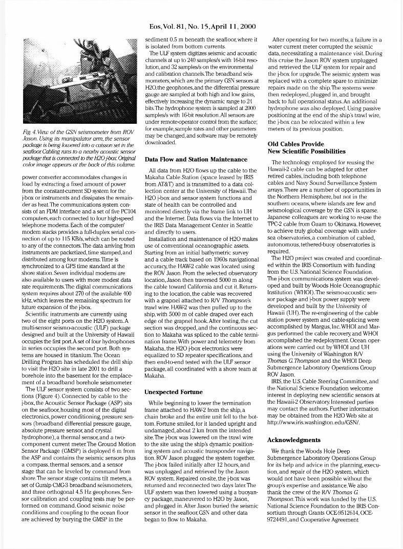
Fig. 3. View of the H20 j-box from ROV Jason during installation on the seafloor. The yellow cable tether connects the j-box to the HAW-2 cable. Original color image appears at the back of this volume.
Eos,Vol.81,No. 15, April 11,2000
Fig. 4. View of the GSN seismometer from ROV Jason. Using its manipulator arm, the sensor package is being lowered into a caisson set in the seafloor Cabling runs to a nearby acoustic sensor package that is connected to the H20 j-box. Original color image appears at the back of this volume.
power converter accommodates changes in load by extracting a fixed amount of power from the constant-current SD system for the j-box or instruments and dissipates the remainder as heat.The communications system consists of an FDM interface and a set of five PC 104 computers, each connected to four high-speed telephone modems. Each of the computer/ modem stacks provides a full-duplex serial connection of up to 115 KB/s, which can be routed to any of the connectors.The data arriving from instruments are packetized, time stamped, and distributed among four modemsTime is synchronized to a GPS time standard at the shore station. Seven individual modems are also available to users with more modest data rate requirements.The digital communications system requires about 270 of the available 400 kHz, which leaves the remaining spectrum for future expansion of the j-box.
Scientific instruments are currently using two of the eight ports on the H20 system. A multi-sensor seismo-acoustic (ULF) package designed and built at the University of Hawaii occupies the first port. A set of four hydrophones in series occupies the second port. Both systems are housed in titanium.The Ocean Drilling Program has scheduled the drill ship to visit the H20 site in late 2001 to drill a borehole into the basement for the emplacement of a broadband borehole seismometer.
The ULF sensor system consists of two sections (Figure 4). Connected by cable to the j-box, the Acoustic Sensor Package (ASP) sits on the seafloor, housing most of the digital electronics, power conditioning, pressure sensors (broadband differential pressure gauge, absolute pressure sensor, and crystal hydrophone),a thermal sensor,and a two-component current meter.The Ground Motion Sensor Package (GMSP) is deployed 6 m from the ASP and contains the seismic sensors plus a compass, thermal sensors, and a sensor stage that can be leveled by command from shore.The sensor stage contains tilt meters, a set of Guralp CMG-3 broadband seismometers, and three orthogonal 4.5 Hz geophones. Sensor calibration and coupling tests may be performed on command. Good seismic noise conditions and coupling to the ocean floor are achieved by burying the GMSP in the
sediment 0.5 m beneath the seafloor, where it is isolated from bottom currents.
The ULF system digitizes seismic and acoustic channels at up to 240 samples/s with 16-bit resolution, and 32 samples/s on the environmental and calibration channels.The broadband seismometers, which are the primary GSN sensors at H20,the geophones, and the differential pressure gauge are sampled at both high and low gains, effectively increasing the dynamic range to 24 bits.The hydrophone system is sampled at 2000 samples/s with 16-bit resolution. All sensors are under remote-operator control from the surface; for example, sample rates and other parameters may be changed, and software may be remotely downloaded.
Data Flow and Station Maintenance
All data from H20 flows up the cable to the Makaha Cable Station (space leased by IRIS from AT&T) and is transmitted to a data collection center at the University of Hawaii.The H20 j-box and sensor system functions and state of health can be controlled and monitored directly via the frame link to UH and the Internet. Data flows via the Internet to the IRIS Data Management Center in Seattle and directly to users.
Installation and maintenance of H20 makes use of conventional oceanographic assets. Starting from an initial bathymetric survey and a cable track based on 1960s navigational accuracy, the HAW-2 cable was located using the ROV Jason. From the selected observatory location, Jason then traversed 5000 m along the cable toward California and cut it. Returning to the location, the cable was recovered with a grapnel attached to R/V Thompsons trawl wire. HAW-2 was then pulled up to the ship, with 5000 m of cable draped over each edge of the grapnel hook. After testing, the cut section was dropped, and the continuous section to Makaha was spliced to the cable termination frame.With power and telemetry from Makaha, the H20 j-box electronics were equalized to SD repeater specifications, and then end-to-end tested with the ULF sensor package, all coordinated with a shore team at Makaha.
Unexpected Fortune
While beginning to lower the termination frame attached to HAW-2 from the ship, a chain broke and the entire unit fell to the bottom. Fortune smiled, for it landed upright and undamaged, about 2 km from the intended site.The j-box was lowered on the trawl wire to the site using the ship's dynamic positioning system and acoustic transponder navigation. ROV Jason plugged the system together. The j-box failed initially after 12 hours, and was unplugged and retrieved by the Jason ROV system. Repaired on-site, the j-box was returned and reconnected two days later.The ULF system was then lowered using a buoyancy package, maneuvered to H20 by Jason, and plugged in. After Jason buried the seismic sensor in the seafloor, GSN and other data began to flow to Makaha.
After operating for two months, a failure in a water current meter corrupted the seismic data, necessitating a maintenance visit. During this cruise the Jason ROV system unplugged and retrieved the ULF system for repair and the j-box for upgrade.The seismic system was replaced with a complete spare to minimize repairs made on the ship. The systems were then redeployed, plugged in, and brought back to full operational status. An additional hydrophone was also deployed. Using passive positioning at the end of the ship's trawl wire, the j-box can be relocated within a few meters of its previous position.
O l d Cables Provide N e w Scientific Possibilities
The technology employed for reusing the Hawaii-2 cable can be adapted for other retired cables, including both telephone cables and Navy Sound Surveillance System arrays.There are a number of opportunities in the Northern Hemisphere, but not in the southern oceans, where islands are few and seismological coverage by the GSN is sparse. Japanese colleagues are working to re-use the TPC-2 cable from Guam to Okinawa. However, to achieve truly global coverage with undersea observatories, a combination of cabled, autonomous, tethered-buoy observatories is required.
The H20 project was created and coordinated within the IRIS Consortium with funding from the U.S. National Science Foundation. The j-box communications system was developed and built by Woods Hole Oceanographic Institution (WHOI).The seismo-acoustic sensor package and j-box power supply were developed and built by the University of Hawaii (UH).The re-engineering of the cable station power system and cable-splicing were accomplished by Margus,Inc.WHOI and Mar-gus performed the cable recovery, and WHOI accomplished the redeployment. Ocean operations were carried out by WHOI and UH using the University of Washington R/V Thomas G. Thompson and the WHOI Deep Submergence Laboratory Operations Group ROV Jason.
IRIS, the U.S. Cable Steering Committee, and the National Science Foundation welcome interest in deploying new scientific sensors at the Hawaii-2 Observatory. Interested parties may contact the authors. Further information may be obtained from the H20 Web site at http://www.iris.washington.edu/GSN/.
Acknowledgments
We thank the Woods Hole Deep Submergence Laboratory Operations Group for its help and advice in the planning, execution, and repair of the H20 system, which would not have been possible without the group's expertise and assistance. We also thank the crew of the R/V Thomas G. Thompson.This work was funded by the U.S. National Science Foundation to the IRIS Consortium through Grants OCE-9512614,OCE-9724491, and Cooperative Agreement

Page 157
Page 162
. ".
Eos,Vol. 81, No. 15, April 11, 2000
Hawaiian Islands
AT&T Makah. Cable Station
Oahu
Fig. I. (Left) The Hawaii-2 Observatory at 27' 52.916'N, 141 ' 59.504"w is sited 1750 km eastnortheast of Honolulu. The site lies between the Murray and Molokaj Fracture Zones at 4979 m depth on about 100 m of predominantly terrigeneous, pelagic clay. The oceanic crust is of Eocene age (45-50 m.y.) and is normal but fast spreading with a spreading half-rate of 7 cm/y. (Center) The path of the Hawaii·2 Cable runs between Oahu and Kauai. then heads northeast toward California. (Right) The AT&T Makaha Cable Station on western Oahu is connected via a leased 256 KBls Frame Relay circuit to the University of Hawaii for data transmission to a data collection center and the Internet.
H20 Seismic Data
• 2 ~
c :0
0 ;; Hj
C>
0 -2 c
~ ." ·4 ~
Z C. E <
48 50 52 54 56 58 60 62 64 66 88
Minutes After 0900Z, October 16,1999
fig. 2. The magnitude 7.0 Hector Mine earthquake on October I6, I999, in southern California recorded at the H20 site at 2550 km distance. Two orthogonal horizontal and the vertical (Z) components are shown, Jowpass filtered at 0.2 Hz. rortuitous!y, the HI component is aligned nearly radially along the great circle from the earthquake, showing the compressional body waves and Raleigh wave similar to the vertical. The transverse H2 component shows shear waves and the Love wave.
Eos,Vol. 81, No. 15, April 11 ,2000
Fig. 3. View of the H20 j-box from ROV Jason during instal/ation on the seafloor. The yellow cable tether connects the j-box to the HAW2 cable.
Fig. 4. View of the GSN seismometer from ROV Jason. Using its manipulator arm, the sensor package is being lowered into a caisson set in the seafloor. Cabling runs to a nearby acoustic sensor package that is connected /J) the H20 fbox.
Page 162
Page 163


![MAGYAR Bevezetés A fényképezőgép kommunikációs szoftvere · 2013-01-27 · EOS 600D EOS 550D EOS 500D EOS 450D EOS 1100D EOS 1000D ... [Canon EOS Utility] lehetőséget, majd](https://img.dokumen.tips/doc/110x75/5e519523f2de307dbc3d6640/magyar-bevezets-a-fnykpezgp-kommunikcis-2013-01-27-eos-600d-eos.jpg)