Embed Size (px)
Citation preview

NOAA/NESDIS/OSPO OSPO/ESPC-ATMO-WIVP15-01-V1.0 ESPC-RIBK-13-090024 Baseline Date: June 18, 2014 NVPWPS Algorithm Theoretical Basis Document
Version 1.0 ii June 2014
Environmental Satellite Processing Center
(ESPC)
NOAA VIIRS Polar Winds Product System (NVPWPS)
Algorithm Theoretical Basis Document Version 1.0, June 18, 2014
Prepared by: Jaime Daniels, NOAA/NESDIS/STAR Wayne Bresky, IMSG, Inc. Jeff Key, NOAA/NESDIS/STAR Steve Wanzong, UW/CIMSS Andrew Bailey, IMSG, Inc. U.S. Department of Commerce National Oceanic and Atmospheric Administration (NOAA) National Environmental Satellite, Data, and Information Service (NESDIS) Office of Satellite and Product Operations (OSPO) Environmental Satellite Processing Center (ESPC)

NOAA/NESDIS/OSPO OSPO/ESPC-ATMO-WIVP15-01-V1.0 ESPC-RIBK-13-090024 Baseline Date: June 18, 2014 NVPWPS Algorithm Theoretical Basis Document
Version 1.4 2 June 2014
Environmental Satellite Processing Center (ESPC)
NOAA VIIRS Polar Winds Product System
Algorithm Theoretical Basis Document
June 18, 2014
CCR02673
Prepared by:
Meizhu Fan, IMSG Hongming Qi, NOAA/NESDIS/OSPO/SPSD
U.S. Department of Commerce National Oceanic and Atmospheric Administration (NOAA)
National Environmental Satellite, Data, and Information Service (NESDIS) Office of Satellite and Product Operations (OSPO)
Environmental Satellite Processing Center (ESPC)

NOAA/NESDIS/OSPO OSPO/ESPC-ATMO-WIVP15-01-V1.0 ESPC-RIBK-13-090024 Baseline Date: June 18, 2014 NVPWPS Algorithm Theoretical Basis Document
Version 1.4 3 June 2014
Approval Page
Environmental Satellite Processing Center
(ESPC)
NOAA VIIRS Polar Winds Product System Algorithm Theoretical Basis Document
Version 1.0, June 18, 2014
CCR02673
GROUP: ESPC eApproval NAME: Hongming Qi, PAL
GROUP: ESPC eApproval NAME:
GROUP: ESPC eApproval NAME: Lindsley Bodden, Contract Manager
GROUP: ESPC

NOAA/NESDIS/OSPO OSPO/ESPC-ATMO-WIVP15-01-V1.0 ESPC-RIBK-13-090024 Baseline Date: June 18, 2014 NVPWPS Algorithm Theoretical Basis Document
Version 1.4 4 June 2014
DOCUMENT HISTORY
The Document History identifies the origination of and subsequent revisions to the NVPWPS Algorithm Theoretical Basis Document since the baseline release. This page will become a permanent part of this document.
Version Number Date Description of
Change/Revision Section/Pages
Affected
Changes Made by Name/Title/ Organization
1.0 Initial Document All 1.0 Technical Edit All Marilyn Gross, ETDT, SGT
1.0 Quality Assessment All

NOAA/NESDIS/OSPO OSPO/ESPC-ATMO-WIVP15-01-V1.0 ESPC-RIBK-13-090024 Baseline Date: June 18, 2014 NVPWPS Algorithm Theoretical Basis Document
Version 1.4 5 June 2014
TABLE OF CONTENTS
Page LIST OF TABLES ..........................................................................................................7
LIST OF FIGURES........................................................................................................8
1. INTRODUCTION ....................................................................................................10
1.1. Product Overview ......................................................................................10 1.1.1. Product Description ...................................................................10 1.1.2. Product Requirements ..............................................................10
1.2. Satellite Instrument Description ..............................................................11
2. ALGORITHM DESCRIPTION ...............................................................................13
2.1. Processing Outline ....................................................................................13
2.2. Algorithm Input ..........................................................................................17 2.2.1 Primary Sensor Data .................................................................17 2.2.2 Ancillary Data ..............................................................................18 2.2.3 Derived Data ...............................................................................18
2.3. Theoretical Description ............................................................................19 2.3.1. Physical Description ...................................................................19
2.3.1.1 Target Selection ...........................................................20 2.3.1.1.1 Spatial Coherence and Cluster Analysis Methods 21
2.3.1.2 Feature Tracking ..........................................................22 2.3.1.3 Target Height Assignment .........................................24
2.3.2. Mathematical Description .........................................................25 2.3.2.1 Target Selection ..........................................................25
2.3.2.1.1 Target Selection Tests ...............................................27 2.3.2.2 Feature Tracking .........................................................34
2.3.2.2.1 Sum-of-Squared Difference Method .......................36 2.3.2.2.2 Nested Tracking .........................................................39 2.3.2.2.3 Feature Tracking Gross Error Tests .......................41
2.3.2.3 Target Height Assignment .........................................44 2.3.2.3.1 Height Assignment Quality Tests ............................47
2.3.2.4 Product Quality Control ..............................................48 2.3.2.4.1 Quality Indicator (QI) Method ...................................48 2.3.2.4.3 Expected Error Method ..............................................53
2.4. Algorithm Output ......................................................................................54

NOAA/NESDIS/OSPO OSPO/ESPC-ATMO-WIVP15-01-V1.0 ESPC-RIBK-13-090024 Baseline Date: June 18, 2014 NVPWPS Algorithm Theoretical Basis Document
Version 1.4 6 June 2014
2.4.1 Product Output ............................................................55 2.4.2 Diagnostic Information ...............................................56 2.4.3 Product Quality Information .......................................58 2.4.4 Metadata Information .................................................58
2.5. Performance Estimates ............................................................................62 2.5.1. Test Data Description ................................................................62 2.5.2. Sensor Effects ............................................................................62 2.5.3. Retrieval Errors...........................................................................63
2.6. Practical Considerations ..........................................................................64 2.6.1. Numerical Computation Considerations .................................64 2.6.2. Programming and Procedural Considerations ......................65 2.6.3. Quality Assessment and Diagnostics .....................................65 2.6.4. Exception Handling ....................................................................65
2.7. Validation ....................................................................................................66
3. ASSUMPTIONS AND LIMITATIONS..................................................................69
3.1. Performance Assumptions ......................................................................69
3.2. Potential Improvements ...........................................................................69
4. REFERENCES .........................................................................................................70

NOAA/NESDIS/OSPO OSPO/ESPC-ATMO-WIVP15-01-V1.0 ESPC-RIBK-13-090024 Baseline Date: June 18, 2014 NVPWPS Algorithm Theoretical Basis Document
Version 1.4 7 June 2014
LIST OF TABLES Page
Table 1-1: Requirements for the VIIRS Polar Winds Product ............................................. 10 Table 1-2: VIIRS Bands. M = Moderate resolution bands; I = Imagery resolution bands ... 12 Table 2-1: Summary of target scene size and image time interval that .............................. 25 Table 2-2: Derived Motion Winds Failure Codes. ............................................................... 27 Table 2-3: Contrast constants and thresholds used for target selection. ............................ 29 Table 2-4: Summary of the DMW gross error quality control tests performed. ................... 44 Table 2-5: Acceptable height range to use as a function of channel used and tracer type 48 Table 2-6: Test weights used for each normalized QI component test. .............................. 52 Table 2-7: Accuracy and precision estimates of the VPW product derived from Soumi-NPP/VIIRS M15 channel imagery over the period September 1, 2013 – January 15, 2014 in the Northern Hemisphere. These estimates were determined from comparisons to collocated radiosonde wind observations at 00 and 12 UTC. The VPW product accuracy and precision specifications from Table 1-1 are included in this table for comparison. ...... 64 Table 2-8: Accuracy and precision estimates of the VPW product (whose QI ≥ 60) derived from Soumi-NPP/VIIRS M15 channel imagery over the period September 1, 2013 – January 15, 2014 in the Southern Hemisphere. These estimates were determined from comparisons to collocated radiosonde wind observations at 00 and 12 UTC. The VPW product accuracy and precision specifications from Table 1-1 are included in this table for comparison. ........................................................................................................................ 64 Table 2-9: Comparison statistics between VPW products computed using the M15 band (10.76um), NCEP GFS short-term forecast winds, and radiosonde wind observations for the period September 1, 2013 – January 15, 2014. These estimates were determined from comparisons to collocated radiosonde winds at 00 and 12 UTC. ....................................... 68

NOAA/NESDIS/OSPO OSPO/ESPC-ATMO-WIVP15-01-V1.0 ESPC-RIBK-13-090024 Baseline Date: June 18, 2014 NVPWPS Algorithm Theoretical Basis Document
Version 1.4 8 June 2014
LIST OF FIGURES Figure 1-0-1. VIIRS detector footprint aggregation scheme for building imagery pixels. .... 11 Figure 2-1. The gray region represents the overlap in three orbits where the polar winds are derived for VIIRS. ............................................................................................................... 14 Figure 2-2. High-level flowchart of the ABI Derived Motion Wind Algorithm. ...................... 16 Figure 2-3. Tracking Error Lower Limit (TELL) is a function of image registration accuracy and image separation time. (Jedlovek and Atkinson, 1998) ............................................... 24 Figure 2-4. Image of 11um brightness temperature (left) and the 11um brightness temperature gradient (right) from the GOES-12 imager instrument. The white boxes show the target scenes at there original locations. The green boxes show the target scenes which have been repositioned at the pixel location containing the maximum brightness temperature gradient as indicated by the yellow dot. ......................................................... 26 Figure 2-5. Scatter diagram of window channel IR local mean radiance and standard deviation values for a single target scene. Each point in the figure represents a 3x3 array of pixels constructed from 4-km GOES IR radiance data. The cluster of points near 80 is ass ........................................................................................................................................... 32 Figure 2-6. Histogram plots of local mean infrared radiance values for a single target scene: (Left) For the entire target scene, (Right) Filtered sample with Gaussian curves fitted to the peaks. The peak on the left is associated with a single cloud layer. ................................. 34 Figure 2-7. Schematic showing the basic concepts associated with the feature tracking algorithm. Targets are selected from the middle image of a three-image loop and tracked forward and backward in time via the SSD method. The two displacements are avera ..... 35 Figure 2-8. Table (a square array) of values specifying the order of positions to search within the lag matrix as part of the spiral search algorithm. ................................................ 38 Figure 2-9. Example of a typical correlation surface for the Sum-of-Squared Difference (SSD) tracking method for 4km infrared imagery. The cool (blue) colors indicate minimum values while the warm (yellows) colors indicate relative maxima. ...................................... 39 Figure 2-10. Schematic of the nested tracking approach. The white vectors show the local motion vectors successfully derived for each possible 5x5 box within a larger 15 x 15 target scene. The red vector on the right is the resulting motion vector if one were to take an average of all the successfully derived local motion vectors. ............................................. 39 Figure 2-11. Motion clusters identified by DBSCAN clustering routine. Green dots indicate line and element displacements belonging to the largest cluster. Red dots indicate line and element displacements belonging to the second largest cluster. Blue dots represent ....... 41 Figure 2-12. Example of the vector field produced with nested tracking before (left) and after (right) DBSCAN is applied to find the largest cluster. The forecast vector (blue) is shown for comparison. ....................................................................................................... 41 Figure 2-13. Cloud-top pressure distribution for a single target scene. The values associated with the largest cluster are shown in green. ..................................................... 45 Figure 2-14. Idealized temperature profile highlighting the cloud height assignment problem posed by low-level temperature inversions. ....................................................................... 46 Figure 2-15. Histogram of the final (weighted) QI values for Meteosat-8 DMWs at 12 UTC on 04 August 2006 ............................................................................................................. 53

NOAA/NESDIS/OSPO OSPO/ESPC-ATMO-WIVP15-01-V1.0 ESPC-RIBK-13-090024 Baseline Date: June 18, 2014 NVPWPS Algorithm Theoretical Basis Document
Version 1.4 9 June 2014
Figure 2-16. Cloud-drift winds derived from VIIRS 10.67um imagery at 1351 UTC on January 14, 2014. High-level (100-400 hPa) winds are shown in violet; mid-level (400-700 hPa) winds are shown in cyan; and low level winds (below 700 hPa) are shown in yellow. 55

NOAA/NESDIS/OSPO OSPO/ESPC-ATMO-WIVP15-01-V1.0 ESPC-RIBK-13-090024 Baseline Date: June 18, 2014 NVPWPS Algorithm Theoretical Basis Document
Version 1.4 10 June 2014
1. INTRODUCTION
This Algorithm Theoretical Basis Document (ATBD) provides a description of and the physical basis for the estimation of atmospheric wind from observations from the Visible Infrared Imaging Radiometer Suite (VIIRS) flown on the Suomi- National Polar-orbiting Partnership (NPP) satellite.
1.1. Product Overview
1.1.1. Product Description
The VIIRS Polar Winds (VPW) product is created in the overlap region of a sequence of orbits to arrive at an estimate of atmospheric motion for a set of targeted tracers viewed in the longwave window region. The targeted tracers are well-defined cloud edges. The wind product consists of the speed, direction, and height of these identified tracers. The product is generated approximately every 101 minutes in both the northern and southern polar regions (i.e., Arctic and Antarctic) and is available poleward of about 65o latitude.
1.1.2. Product Requirements
Table 1-1: Requirements for the VIIRS Polar Winds Product
Capability Threshold Requirement
Vertical Coverage Surface to tropopause
Geographic Coverage Poleward of 65 degrees latitude
Horizontal Resolution ~19 km
Vertical Reporting Interval At cloud tops
Mapping Uncertainty 0.4 km (at NADIR); 1.5km (Edge of Scan)
Measurement Range Speed: 3-100 m/s; Direction: 0-360 degrees
Measurement Accuracy 7.5 m/s (Mean Vector Difference)
Measurement Precision 4.2 m/s
Latency 30 min (after receipt of all data needed to compute VPW)
Refresh 101 min
Format NetCDF4, BUFR, McIDAS MD

NOAA/NESDIS/OSPO OSPO/ESPC-ATMO-WIVP15-01-V1.0 ESPC-RIBK-13-090024 Baseline Date: June 18, 2014 NVPWPS Algorithm Theoretical Basis Document
Version 1.4 11 June 2014
1.2. Satellite Instrument Description
The Visible Infrared Imager Radiometer Suite (VIIRS) was launched October 28, 2011 as part of the NPOESS Preparatory Project (NPP). NPP was renamed the Suomi National Polar-orbiting Partnership (S-NPP) soon thereafter. VIIRS was designed to improve upon the capabilities of the operational Advanced Very High Resolution Radiometer (AVHRR) and provide observation continuity with NASA’s Earth Observing System’s (EOS) Moderate Resolution Imaging Spectroradiometer (MODIS). S-NPP VIIRS is a multispectral cross-track scanning sensor. It has 22 spectral bands that consist of 15 reflective solar VNIR/SWIR bands (RSB) and 7 thermal emissive bands (Cao et al. 2013). Table 1-2 provides a summary listing of these bands. The spectral bands are categorized as moderate resolution, imagery, and day–night bands. The spatial resolution at nadir is approximately 750m for the moderate bands and 375m for the imagery bands (Cao et al. 2013). Unlike the previous instruments such as MODIS and AVHRR, the ground samples of VIIRS observation are aggregated in scan direction to limit changes of spatial resolution across the entire swath (Figure 1-1; Hutchison and Cracknell 2005; Cao et al. 2013). VIIRS consequently exhibits a pixel growth factor of only two both along track and along scan, compared with a growth factor of six along scan which would be realized without the aggregation scheme. This scanning approach allows VIIRS to provide imagery at 800 m resolution or finer globally. Furthermore, VIIRS has a wider swath (3000 km) than MODIS (2320 km) [Hutchison and Cracknell, 2006].
Figure 1-1. VIIRS detector footprint aggregation scheme for building imagery pixels.

NOAA/NESDIS/OSPO OSPO/ESPC-ATMO-WIVP15-01-V1.0 ESPC-RIBK-13-090024 Baseline Date: June 18, 2014 NVPWPS Algorithm Theoretical Basis Document
Version 1.4 12 June 2014
Table 1-2: VIIRS Bands. M = Moderate resolution bands; I = Imagery resolution bands
VIIRS Band
Central
Wavelength (um)
Wavelength Range
(um)
Band
Explanation
Spatial Resolution (m)
at nadir M1 0.412 0.402 - 0.422
Visible
750 m
M2 0.445 0.436 - 0.454 M3 0.488 0.478 - 0.488 M4 0.555 0.545 - 0.565 M5 0.672 0.662 - 0.682 M6 0.746 0.739 - 0.754 Near IR M7 0.865 0.846 - 0.885 M8 1.240 1.23 - 1.25
Shortwave IR M9 1.378 1.371 - 1.386 M10 1.61 1.58 - 1.64 M11 2.25 2.23 - 2.28 M12 3.7 3.61 - 3.79 Medium-wave IR M13 4.05 3.97 – 4.13 M14 8.55 8.4 – 8.7
Longwave IR M15 10.763 10.26 – 11.26 M16 12.013 11.54 – 12.49 DNB 0.7 0.5 – 0.9 Visible 750 m across full scan
11 0.64 0.6 – 0.68 Visible
375 m 12 0.865 0.85 – 0.88 Near IR 13 1.61 1.58 – 1.64 Shortwave IR 14 3.74 3.55 – 3.93 Medium-wave IR 15 11.45 10.5 – 12.4 Longwave IR

NOAA/NESDIS/OSPO OSPO/ESPC-ATMO-WIVP15-01-V1.0 ESPC-RIBK-13-090024 Baseline Date: June 18, 2014 NVPWPS Algorithm Theoretical Basis Document
Version 1.4 13 June 2014
2. ALGORITHM DESCRIPTION
The Derived Motion Winds Algorithm (DMWA) to be applied to VIIRS observations was originally developed for the future GOES-R ABI instrument (Bresky et al, 2013, Daniels et al, 2012). There are a number of basic steps involved in the process of generating Derived Motion Winds (DMW) from VIIRS: • Obtain a set of at least three consecutive precisely calibrated, navigated and co-
registered orbital images in a selected spectral channel. • Locate and select a set of suitable targets in the middle image domain. • For each image pair in the image triplet, use a correlation algorithm to derive the
motion most representative for the target scene. When tracking cloudy target scenes (as determined by using the official JPSS cloud mask product) using the VIIRS M15 band (10.7um) the correlation algorithm is used in conjunction with a nested tracking algorithm where the following steps are performed: • Apply the correlation algorithm to smaller sub-targets within each target scene in
order to derive a set of local motion vectors for each target scene. • Analyze the local motion field with a cluster analysis algorithm in order to extract the
dominant motion within the target scene. • Assign a height to the derived winds using cloud height pixel level information
(obtained from running a precursor cloud algorithm) from the dominant cluster. • Average the vectors derived from each of the image pairs to arrive at the final set of
DMWs. • Perform quality control on the DMWs and assign quality indicators to each of the
DMWs. A target scene is represented by an N x N array of pixels that defines a suitable feature in the image whose movement can be tracked in time. The size of this array is a function of the spatial and temporal resolution of the imagery and the scale of the intended feature to be tracked. One of the challenges of deriving atmospheric motion winds operationally from satellites is to determine and utilize imagery taken at frequencies appropriate to the scales resolvable by operational numerical weather prediction systems while at the same time meeting production demands that require routine full disk coverage.
2.1. Processing Outline
In order to estimate motion, one must have a sequence of images separated by some, preferably fixed and relatively short, time interval. The DMW algorithm described here uses a sequence of three orbital images to compute a pair of vector displacements (one for an earlier time step and one for a later time step) that are averaged to obtain the final motion estimate. The current version of the algorithm requires that the three images be equal in size. The VPW products are generated over the area where the three sequential orbital images overlap. Figure 2-1 shows the overlap (white area) of three consecutive VIIRS orbits that are needed for winds derivation. The DMWA uses the middle image to perform

NOAA/NESDIS/OSPO OSPO/ESPC-ATMO-WIVP15-01-V1.0 ESPC-RIBK-13-090024 Baseline Date: June 18, 2014 NVPWPS Algorithm Theoretical Basis Document
Version 1.4 14 June 2014
the initial feature targeting, then searches the before and after images for traceable (coherent) features to derive motion estimates.
Figure 2-1. The gray region represents the overlap in three orbits where the polar winds are derived for VIIRS.
The basic processing outline for the DMWA is summarized in Figure 2-2. The algorithm is designed to run on segments of data provided by the framework and consisting of multiple scan lines. Processing begins after a data buffer containing the brightness temperature values from three consecutive images is filled. The data buffer also contains output from the cloud mask and cloud height algorithms that must execute before the DMWA. It should be noted that the cloud data is only required for the middle image time because this is the image that is processed for targets. On the other hand, brightness temperature values are required for all three image times because this is the quantity being tracked. In practice, the buffer is a data structure holding the 2-dimensional arrays of brightness temperatures for three image times and the cloud information for a single image time.

NOAA/NESDIS/OSPO OSPO/ESPC-ATMO-WIVP15-01-V1.0 ESPC-RIBK-13-090024 Baseline Date: June 18, 2014 NVPWPS Algorithm Theoretical Basis Document
Version 1.4 15 June 2014
Once the data buffer is full, the middle portion of the buffer is divided into small “target” scenes N x N pixels and each scene is analyzed to determine if it is a suitable tracer. Only the brightness temperature field from the middle image time is processed for targets and it is these targets that will be tracked over time to derive the motion. Processing only the middle portion of the buffer allows for the features to drift over time but still remain within the domain of the buffer. Within each target scene, the algorithm locates the strongest 2-D gradient in the brightness temperature field and re-centers the N x N target scene at this location. A brightness temperature gradient threshold is used to prevent target selection on very weak gradients. After the target scene is re-centered on the maximum gradient, tests are performed to determine whether or not the scene would be a suitable tracer. These tests eliminate target scenes that lack the gradients necessary to track reliably while also removing scenes that are suspected to contain multiple cloud layers. If a potential tracer makes it through the target quality control, a search region, much larger in size than the target scene, is defined in each of the tracking images. At this point, depending on the channel being processed, one of two tracking strategies is employed. Both strategies use the Sum of Squared Differences (SSD) similarity measure to locate the target scene in the preceding and succeeding images. When processing cloud-top features from the 10.76um channel, a tracking strategy called nested tracking is used to estimate motion. In this approach, a small 5x5 pixel box is “nested” within the outer target scene and a local motion vector is derived at each interior pixel. A 2-pixel offset is used near the boundary of the outer target scene. The field of local motion vectors that results is then analyzed with a cluster analysis algorithm to find the dominant motion. The dominant motion is computed by averaging the displacements associated with the largest motion cluster found by using a cluster analysis algorithm. The wind vector is then assigned a representative height after examining the cloud top pressures associated with the pixels in the largest cluster. The tracking approach uses a forecast wind (from the center of the target scene) to locate and place the center of the search region in the next image. This practice of using the forecast to “guide” the search serves two purposes. First, it reduces the number of “false positives” in the tracking step. Secondly, it minimizes the computational expense of the search. During the tracking process, correlation thresholds are applied to screen out false positives. When nested tracking is employed, only matching scenes possessing a correlation score of 0.8 or higher (1.0 is perfect) are allowed to influence the final solution.

NOAA/NESDIS/OSPO OSPO/ESPC-ATMO-WIVP15-01-V1.0 ESPC-RIBK-13-090024 Baseline Date: June 18, 2014 NVPWPS Algorithm Theoretical Basis Document
Version 1.4 16 June 2014
Figure 2-2. High-level flowchart of the ABI Derived Motion Wind Algorithm.

NOAA/NESDIS/OSPO OSPO/ESPC-ATMO-WIVP15-01-V1.0 ESPC-RIBK-13-090024 Baseline Date: June 18, 2014 NVPWPS Algorithm Theoretical Basis Document
Version 1.4 17 June 2014
Two sub-vectors are generated in the tracking process, one vector for the backward time step and one vector for the forward time step. Accelerations between sub-vectors exceeding a user-defined threshold (5 or 10 m/s depending on band) are not permitted (vectors are discarded). In addition, gross errors in the height assignment and tracking estimates are removed by comparing the satellite-derived motion wind to a numerical forecast wind and discarding those satellite-derived wind vectors which differ significantly from the forecast wind. Once the last line segment is processed, the entire set of derived winds undergoes a more rigorous quality control process. Two related algorithms will make up the Automatic Quality Control (AQC) for the VPW product processing. The first one is the quality indicator (QI), based on work done at EUMETSAT (Holmlund, 1998). The second is the Expected Error (EE) principles developed at the Bureau of Meteorology, Australia (LeMarshall et al. 2004).
2.2. Algorithm Input
This section describes the input needed to process the DMWs. While the DMWA uses information at the pixel level (e.g., cloud mask, cloud height), the derived motion is representative of a group of pixels (i.e., a scene within a target box of size N x N pixels). The DMWA is currently designed to process winds only after a data buffer has been filled with brightness temperature data from all three images in the tracking sequence. Cloud height and cloud mask information for the middle image time is also required. The buffer must be large enough to capture the motion of features up or down in the image. Consequently, the DMWA processes only a portion of the buffer (a middle strip the same width as the target box size) for suitable tracers. Processing proceeds from west to east until the earth edge is encountered or no more elements exist in the line segment. The process is repeated until the number of lines remaining in the line segment is smaller than the number of lines that make up the target scene. At this point the extra lines are saved in the buffer and control is returned to the framework until the next line segment is read into memory. The following sections describe the actual input needed to run the DMWA.
2.2.1 Primary Sensor Data The list below contains the primary sensor data to be used by the DMWA. By primary sensor data, we mean information that will be derived solely from the VIIRS observations and geolocation information. The sensor data is used at it original resolution.
• Calibrated and navigated radiances for VIIRS channel M15 (10.76um) for the middle
image time of the loop sequence. • Calibrated and navigated brightness temperatures for VIIRS channel M15 (10.76um)
for three consecutive orbital images.
NOAA/NESDIS/OSPO OSPO/ESPC-ATMO-WIVP15-01-V1.0 ESPC-RIBK-13-090024 Baseline Date: June 18, 2014 NVPWPS Algorithm Theoretical Basis Document
Version 1.4 18 June 2014
2.2.2 Ancillary Data The following list briefly describes the ancillary data required to run the DMWA. By ancillary data, we mean data that will require information not included in the VIIRS observations or geolocation data.
• Land mask / Surface type A land mask file is needed such that each VIIRS pixel can be classified as being over land or water.
• DMWA configuration file A configuration file is needed to set six variables within the DMWA processing algorithm: 1. VIIRS channel number – Channel number to use for feature tracking 2. Time step between images 3. Target box size – In pixel space 4. Nested tracking flag – to enable or disable nested tracking. 5. Expected Error (EE) filter flag 6. Clear-sky WV flag – to enable or disable clear sky processing.
• Numerical Weather Prediction (NWP) Forecast Data
1. Short-term forecast temperature and wind data on pressure surfaces from
National Centers for Environmental Prediction’s (NCEP) Global Forecast System (GFS) model are used to calculate target heights and for calculating model shear and model temperature gradients used in the Expected Error algorithm described in Section 3.4.2.4.2. Details concerning the preprocessing of NWP forecast data can be found in the AIADD Document.
2. Short-term GFS forecast wind profiles are also used to center the search box on the predicted locations of targeted features being tracked in the first and last images of the loop sequence
• Expected Error Coefficients File
1. A set of regression coefficients corresponding to a number of predictors used to
compute the Expected Error quality flag that is appended to each DMW that is computed. The details of this approach are described in Section 2.3.2.4.2.
2.2.3 Derived Data

NOAA/NESDIS/OSPO OSPO/ESPC-ATMO-WIVP15-01-V1.0 ESPC-RIBK-13-090024 Baseline Date: June 18, 2014 NVPWPS Algorithm Theoretical Basis Document
Version 1.4 19 June 2014
This section lists the input data that must be derived before the DMWA is executed. The output of several upstream cloud product algorithms are used in the DMWA derivation process and include the following:
• Cloud Mask The cloud mask is used by the DMWA as part of the cloud amount test when selecting which target scenes to process. It is also used to screen out pixels that do not have a cloud top pressure associated with them.
• Cloud top pressure, cloud top pressure quality, and cloud top temperature This information is used by the DMWA to assign a representative height to the target scene being tracked.
• Low level inversion flag This information is used by the DMWA to assign a representative height to the scene being tracked within a GFS model designated low-level inversion.
• Solar zenith angle This information is used by the DMWA to determine day/night pixels.
• Cloud top height and temperature error estimates This information is diagnostic output.
2.3. Theoretical Description
2.3.1. Physical Description
Estimation of atmospheric flow from motions in sequential satellite imagery This section discusses the theory behind the challenge of estimating atmospheric flow from motions in sequential satellite imagery. Atmospheric motion is determined through the tracking of features in time. Identifying features to be tracked is the first step in the process. These features can be clouds, or in the case of clear-sky conditions, moisture gradients. Visible and infrared observations are typically used to extract atmospheric motion. The choice of spectral band will determine the intended target (cloud or moisture gradient) to be tracked, its height in the atmosphere, as well as the scale of its motion. As an example, operational GOES DMWs can be found in the mid- to upper tropospheric levels (100–600 hPa) through the use of the mid-wave (6.7um – 7.3um) water vapor channels and longwave (10.7um) infrared (LWIR) channel for deriving vectors. In the lower levels (600–

NOAA/NESDIS/OSPO OSPO/ESPC-ATMO-WIVP15-01-V1.0 ESPC-RIBK-13-090024 Baseline Date: June 18, 2014 NVPWPS Algorithm Theoretical Basis Document
Version 1.4 20 June 2014
950 hPa), DMWs are provided by a combination of the visible (VIS) and IR channels, depending on the time of day. During daylight imaging periods, the VIS channel usually provides superior low-level tracer detection than the LWIR channel due to its finer spatial resolution and decreased susceptibility to attenuation by low-level moisture. During night-time imaging periods, the shortwave (3.9um) infrared (SWIR) channel compliments the LWIR channel to derive DMWs. The SWIR channel is a slightly “cleaner” window channel than the LWIR (less WV attenuation), making it more sensitive to warmer (lower tropospheric) temperature features (Dunion and Velden, 2002). The SWIR channel is also not as sensitive as the LWIR channel to cirrus clouds that may obscure low-level cloud tracers. These two characteristics make it a superior channel for producing low level DMWs at night. In the case of VIIRS, the LWIR M15 band will be used to track cloud features at low (below 700 hPa), mid (400-700hPa), and high (above 400 hPa) levels of the atmosphere. As described previously, each target is an N x N array of VIIRS pixel measurements (scene) that encapsulate a suitable feature whose movement is tracked in time. The size of this array is a function of both the spatial and temporal resolution of the imagery and the scale of the intended feature to be tracked. Generally speaking, a small target box yields a noisier motion field than one generated with a larger target box. Conversely, if the target scene is too large, the algorithm will tend to measure the mean flow of the pixels in the target scene (i.e. a spatial average of several motions) rather than the intended instantaneous wind at a single point. These considerations need to be kept in mind when choosing the optimal target box size.
2.3.1.1 Target Selection The objectives of the target selection process are to select high quality target scenes that: i) capture the intended target (i.e., clouds or clear-sky water vapor gradient), ii) contain sufficient contrast, and iii) do not contain a mix of multi-layered clouds. Target scenes that posses these characteristics are more amenable to precision tracking and height assignment that result in more accurate atmospheric wind estimates. Target scenes are centered at pixel locations where the magnitude of the brightness temperature gradient is large. In other words, these target scenes are centered over cloud edges or tight moisture gradients in clear-sky conditions. To assure that only high quality targets are selected, all potential target scenes first undergo a spatial coherence and cluster analysis (Coakley & Bretherton, 1982) check. The primary goal of this analysis is to identify the presence of a coherent signal in the target scene that indicates a dominant single layer cloud in the target scene. The spatial-coherence method attempts to identify the presence of cloud layers in each target scene by identifying the portions of the region that exhibit a high degree of local uniformity in the pixel-level emitted radiances. A high degree of uniformity will exist for regions that are cloud-free or for regions completely covered by cloud at a uniform height. For targets that are not completely covered by clouds, the emitted radiances can vary significantly from one pixel to the next.

NOAA/NESDIS/OSPO OSPO/ESPC-ATMO-WIVP15-01-V1.0 ESPC-RIBK-13-090024 Baseline Date: June 18, 2014 NVPWPS Algorithm Theoretical Basis Document
Version 1.4 21 June 2014
2.3.1.1.1 Spatial Coherence and Cluster Analysis Methods The starting point for spatial-coherence and cluster analysis methods is the model of a well-defined, single-layered system of clouds situated over a relatively uniform background. What is meant by the term “well-defined” and “relatively uniform” will be explained below. The emitted radiance observed by a radiometer viewing such a system is given by I = (1 – C)Ics + C(εcldIcld + tcldIcs) (1) where I is the emitted radiance, C is the fractional cloud cover for the field of view, Ics is the radiance associated with the cloud-free portion of the field of view, i.e. the radiance observed when C = 0. εcld is the mean effective emissivity associated with the cloud layer, tcld is the mean transmissivity, and Icld is the radiance that would be observed for overcast regions, i.e. C = 1, if the clouds were black at the wavelength of observation. The emitted radiance, I, is assumed to be at an infrared (IR) window wavelength so that downward emission above the cloud can be neglected. Likewise, the surface is assumed to be black at the wavelength of observation so that all radiation incident on the surface is absorbed, especially that emitted downward by the cloud. It is assumed that no radiation is reflected by the surface. Over a relatively small region the emission of the clear-sky background, Ics, and the height of the cloud layer, and therefore Icld, are assumed to have little variance. That is, the effects of variations in the thermal emissions associated with the clear-sky background and the height of the cloud layer are small when compared with the effects caused by variations in the fractional cloud cover and the cloud optical properties. If these conditions are met, the background is said to be relatively uniform and the layer is said to be well defined. From (1), the variance of the radiances under such conditions is given by: _ _ ___ ___ (I–I)2 =[(C–C)Ics+(Cεcld – Cεcld)Icld+(Ctcld – Ctcld)Ics]2 (2) where the overbars indicate mean quantitites. The variances of emitted radiances over small areas spanning several image pixels is the key to identifying the portions of a region that are cloud-free or overcast by clouds in a well-defined layer. The variance approaches zero when the mean cloud cover in a region approaches zero. If the mean cloud cover is zero, then the fractional cover in every pixel is also zero (i.e. C=C =0). Where the clouds become sufficiently extensive so that several image pixels are overcast, then for analogous reasons, the variance approaches zero because C=C =1. Often when cloud systems become sufficiently extensive that they cover several image pixels, they also become opaque. A notable exception can be cirrus. For opaque, overcast clouds the variance again becomes zero because ticld = tcld = 0 and εi
cld = εcld = εcldmax. , where, tcld is the cloud transmissivity and εcldmax is the emissivity that the clouds obtain when they become opaque (i.e., where rcldmax is the reflectivity). When pixels become overcast with opaque clouds, the variance in emitted radiances also becomes zero. When pixels become overcast by semitransparent clouds, like cirrus, pixel-to-pixel variations in the cloud optical properties, i.e. εcld and tcld, prevent the variance from dropping to zero. Because clouds appear to vary incoherently on the ~1 × 1 km scale available to current satellite imagers, (2) indicates that

NOAA/NESDIS/OSPO OSPO/ESPC-ATMO-WIVP15-01-V1.0 ESPC-RIBK-13-090024 Baseline Date: June 18, 2014 NVPWPS Algorithm Theoretical Basis Document
Version 1.4 22 June 2014
variances in the emitted radiances for regions that are covered by several image pixels will be nonzero when the region contains broken cloud. The variability will be caused partly by differences in the fractional cloud cover from pixel to pixel and partly by variations in the average cloud optical properties from pixel to pixel. The spatial-coherence method identifies pixels that are overcast by layered clouds where the clouds become opaque, and pixels that are cloud-free by relying on the near-zero variances in emitted radiances for localized collections, or clusters, of the pixels. Collections of pixels that are partly covered by clouds or are overcast by clouds that are semitransparent invariably exhibit relatively larger variances. The application of a simple threshold on the variance of emitted radiances over local sub-regions within each target scene is performed as part of the target selection process in order to identify coherent pixels representative of cloud features and the surface. The cluster analysis method is designed to filter out hard to track multi-layered cloud scenes. It is related to the spatial coherence method in that it starts with the same radiance information (mean and standard deviation values for small sub-regions of the target box), but takes the analysis further to determine if more than one cloud layer is present in the target scene. This analysis involves constructing a histogram of pixel level radiance values within the target scene and then identifying the clusters of warm and cold samples that are assumed to correspond to the surface and the elevated cloud layer, respectively. A second cloud layer is assumed to exist in the target scene if more than a pre-determined percentage (20%) of the radiance values fall outside of the two clusters of warm and cold samples. If a second cloud layer is determined to exist, the target scene is rejected as a suitable target for feature tracking. Further details about how both of these tests are applied are provided in Section 2.3.2.1.
2.3.1.2 Feature Tracking If a target scene survives the selection criteria, then attempts to track this target in the image sequence can commence. Feature tracking involves coherent tracking of clouds or water vapor features over a specified time interval. A key assumption made in this process is that cloud or water vapor features are passive tracers that move with the ambient wind flow. Of course, it is understood that cloud tracers (in particular) are not always passive. There may be growth, decay, or change in cloud top height over the time interval being assessed. Further complicating matters is the fact that some clouds do not move with the wind (i.e. wave clouds) while others track with the wind at a level lower than cloud top (i.e. marine cumulus). Therefore it is important to apply robust quality control to remove retrieved DMWs that are in error as a result of these complicating factors (discussed in Section 3.4.2.4). Clouds grow and decay with lifetimes that vary with their size and location (i.e., land versus ocean). To be effectively tracked, the lifetime of the tracer must be at least as long as the time interval of the image sequence used. The resolution of the imagery is also an important consideration when tracking features in satellite imagery. Merill (1989) and Schmetz et al. (1993) discuss this at length. It is important that the size of the target scene

NOAA/NESDIS/OSPO OSPO/ESPC-ATMO-WIVP15-01-V1.0 ESPC-RIBK-13-090024 Baseline Date: June 18, 2014 NVPWPS Algorithm Theoretical Basis Document
Version 1.4 23 June 2014
(spatial resolution) is consistent with the temporal resolution of the imagery in order to capture the scale of the intended feature being tracked. A critical factor that has a significant impact on the quality of the derived winds, especially at higher temporal resolutions, is the image registration; that is, the stability of the image-to-image navigation. If the stability of the image-to-image navigation is poor for an image sequence, the result will be added noise to the tracking process and poor quality DMWs. Furthermore, use of imagery with high temporal resolution, but coarse spatial resolution, can result in poor quality DMWs. This is especially true for small tracer displacements (i.e., low wind speeds) where image registration uncertainties will dominate the resulting true displacements. Jedlovek and Atkinson (1998) discuss the development of a Tracking Error Lower Limit (TELL) parameter, ℑ , that provides guidance for understanding the trade-offs between spatial and temporal resolution for varying image registration performances. The TELL parameter is given by:
t/)2/( ρ+ℜ=ℑ (3) where: ℜ is the image registration accuracy, ρ is the image spatial resolution, and t is the image separation interval. Figure 2-3 shows the magnitude of the TELL parameter for various values of the image registration accuracy and image separation.

NOAA/NESDIS/OSPO OSPO/ESPC-ATMO-WIVP15-01-V1.0 ESPC-RIBK-13-090024 Baseline Date: June 18, 2014 NVPWPS Algorithm Theoretical Basis Document
Version 1.4 24 June 2014
Figure 2-3. Tracking Error Lower Limit (TELL) is a function of image registration accuracy and image separation time. (Jedlovek and Atkinson, 1998) Small values of TELL (small wind errors) are achieved with good image registration, high resolution data, and relatively large image separation times. However, for atmospheric applications where trackable features change considerably over a short period of time, large separation intervals are not desirable, making values of image resolution and registration accuracy critical parameters in DMW accuracy.
2.3.1.3 Target Height Assignment Assigning a representative height to each cloudy target is achieved by processing pixel-level cloud heights, derived upstream of the DMWA, within the target scene. A detailed description of the upstream cloud height algorithm can be found in the GOES-R ABI Cloud Height Algorithm Theoretical Basis Document (Heidinger, 2010) Target height assignment is considered to be the major source of error for DMWs. A perfectly tracked feature can be rendered useless if it is assigned to the wrong level in the atmosphere. There is also the consideration of how well the final wind actually represents the local wind field at a singular location, height (level) and time. Some clouds do not move with the wind while others follow the wind at a level lower than the cloud top. Additionally, DMWs tend to represent the movement of a layer of the atmosphere, as opposed to the movement of the atmosphere at a particular level (Velden and Bedka 2009).

NOAA/NESDIS/OSPO OSPO/ESPC-ATMO-WIVP15-01-V1.0 ESPC-RIBK-13-090024 Baseline Date: June 18, 2014 NVPWPS Algorithm Theoretical Basis Document
Version 1.4 25 June 2014
2.3.2. Mathematical Description
The GOES-R DMWA approach to derive an individual vector consists of the following general steps, each of which is described in detail in the following sections.
• Locate and select a suitable target in second image (middle image; time=t0) of a prescribed image triplet
• Assign an estimated representative height to the target • Use a pattern matching algorithm to locate the target in the earlier and later image.
Track the target backward in time (to first image; time=t-Δt) and forward in time (to third image; time=t+Δt) and compute corresponding displacement vectors. Compute the mean vector displacement from the two displacement vectors and assign this final DMW to time = t0.
• Perform quality control procedures on the DMW to edit out or flag suspect vectors. Compute and append quality indicators to each DMW.
2.3.2.1 Target Selection Targets are selected from the middle image of the sequence. The size of each target scene will depend on the channel being processed and the scale of the motion being estimated. The target scene is traditionally a square with sides of equal length (in pixels). Table 2-1 summarizes the target scene size and image time separation interval to be employed for each VIIRS channel used to derive DMWs. It should be noted that the horizontal resolution of the DMW product is driven by the size of the target scene used. Consequently, the horizontal resolution of the wind products derived from VIIRS 10.76um band, will be ~19km.
Table 2-1: Summary of target scene size and image time interval that should be used to derive DMWs for VIIRS
Channel Number
Center Frequency (µm)
Target Scene Size (Image lines x elements)
Image Time Interval (mins)
M15 10.76 19x19 101 Before the target selection process begins, the brightness temperature gradient magnitude for each pixel location is computed from equation (4).
∑ ∑=
−=
=
−=
++= +
2
2
2
2
2,
2, )})(({)})(({ ,
k
k
k
kkLineEleElementLine BTWBTWGradient kLinekElek (4)
where: Wk = -1/12, 8/12, 0, -8/12, 1/12 ; for k= -2 to 2

NOAA/NESDIS/OSPO OSPO/ESPC-ATMO-WIVP15-01-V1.0 ESPC-RIBK-13-090024 Baseline Date: June 18, 2014 NVPWPS Algorithm Theoretical Basis Document
Version 1.4 26 June 2014
BT is the pixel level channel brightness temperature Ele refers to an image column Line refers to an image row Figure 2-4 shows an example of a brightness temperature gradient image (right side) derived from brightness temperatures (left side) for the GOES-12 imager. The dark areas on the right side indicate locations where the magnitudes of the brightness temperature gradients are large. These locations exist on the edges of clouds and in the interior of cloud systems where cloud structure exists. It is in these locations where potential acceptable targets are expected to be found. The white boxes shown on the left side show the original target scene locations and the yellow dots show the location of the maximum gradient magnitude in each of these target scenes. The center of every target scene is then repositioned at the pixel containing the maximum gradient magnitude. If the same gradient value occurs in multiple pixels within a target scene, then the first occurrence of the maximum gradient value is the one chosen. The repositioned target scenes are shown in green. The intent of repositioning the target scene at the maximum gradient is twofold. First, it focuses the target scene on a strong feature that is expected to be effectively
tracked
over time. Secondly, it establishes a link between pixels containing the feature being tracked and the pixels contributing to its height assignment (discussed later). Repositioning of the target scenes can result in an irregular spatial distribution of target scenes, and hence, an irregular spatial distribution of the DMW product. The white arrows indicate the direction of
Figure 2-4. Image of 11um brightness temperature (left) and the 11um brightness temperature gradient (right) from the GOES-12 imager instrument. The white boxes show the target scenes at there original locations. The green boxes show the target scenes which have been repositioned at the pixel location containing the maximum brightness temperature gradient as indicated by the yellow dot.

NOAA/NESDIS/OSPO OSPO/ESPC-ATMO-WIVP15-01-V1.0 ESPC-RIBK-13-090024 Baseline Date: June 18, 2014 NVPWPS Algorithm Theoretical Basis Document
Version 1.4 27 June 2014
the image processing, which begins at the top left of the image and moves left to right along the image and then downwards.
2.3.2.1.1 Target Selection Tests All of the potential target scenes undergo a series of quality control tests to determine if the target is a suitable tracer. These ‘target selection’ tests are described below. If a target fails any one of these tests, the target is determined to be a non-suitable tracer and is flagged. Each failure is associated with a unique “flag” value that is saved in the DMW output file. These values are shown in Table 2-2. Table 2-2: Derived Motion Winds Failure Codes.
Derived Motion Wind Quality Control Codes QC_Flag Definition 0 Good wind 1 Maximum gradient below acceptable threshold 2 Target located on earth edge
3 Cloud amount failure (less than 10% cloud cover for cloud track winds or greater than 0% cloud cover for water vapor clear-sky winds)
4 Median pressure failure 5 Bad or missing brightness temperature in target scene 6 Multiple cloud layers present
7 Target scene too coherent (not enough structure for reliable tracking)
8 Tracking correlation below 0.6 (not used for nested tracking) 9 u-component acceleration greater than 10 m/s (5 m/s for visible) 10 v-component acceleration greater than 10 m/s (5 m/s for visible)
11 u- and v- component accelerations greater than 10 m/s (5 m/s for visible)
12 Derived wind slower than 3 m/s
13 Target scene too close to day/night terminator (visible and SWIR only)
14 Median pressure used for height assignment outside acceptable pressure range (channel dependent)
15 Match found on boundary of search region 16 Gross difference from forecast wind (channel dependent)
17
Median pressure (used for height assignment) of largest cluster for first image pair is too different from median pressure of largest cluster for second image pair – only valid for nested tracking
18 Search region extends beyond domain of data buffer 19 Expected Error (EE) too high 20 Missing data in search region

NOAA/NESDIS/OSPO OSPO/ESPC-ATMO-WIVP15-01-V1.0 ESPC-RIBK-13-090024 Baseline Date: June 18, 2014 NVPWPS Algorithm Theoretical Basis Document
Version 1.4 28 June 2014
21 No winds are available for the clustering algorithm 22 No clusters were found Catastrophic Failures Invalid time interval Temporal data not available Line segment swath too small (must contain at least the same number of lines as target box size, usually 15 lines) Search region must be larger than target scene
Table 5 describes the possible failure codes from the initial target selection step through the final QC process. Because target selection is the first step in the AMV derivation process the tests associated with it are described first. The target selection tests are applied in the following order:
1. Zero gradient check 2. Proximity to day/night terminator check 3. Earth edge test (no space pixels allowed) 4. Fractional cloud cover/clear sky test
Note: when processing the upper-level water vapor channel for clear-sky tracers pixels with low-level clouds (CTP >= 600 mb) are considered clear.
5. Contrast test – channel dependent 6. Channel validity test
#6 is the extent of target QC for WV processing Additional target QC performed for visible, SWIR and LWIR winds:
7. Spatial coherence check 8. Multi-layer cloud check
If a target scene fails test #1 the next adjacent target box is processed. If a target fails any of the 2-8 tests the box is shifted by ½ the width of the target box. Zero gradient Test If the maximum gradient found in the target scene is zero the target is discarded and the next adjacent box is processed. Contrast Test Each target scene is required to contain sufficient contrast, which is computed from the range of channel measurements (brightness temperature or reflectance percent) within the target scene. The contrast threshold used is channel dependent and is the product of the contrast constant (shown in Table 2-3) and the ratio of the target scene size used (see Table 4) and the nominal target scene size (7 or 15).
NOAA/NESDIS/OSPO OSPO/ESPC-ATMO-WIVP15-01-V1.0 ESPC-RIBK-13-090024 Baseline Date: June 18, 2014 NVPWPS Algorithm Theoretical Basis Document
Version 1.4 29 June 2014
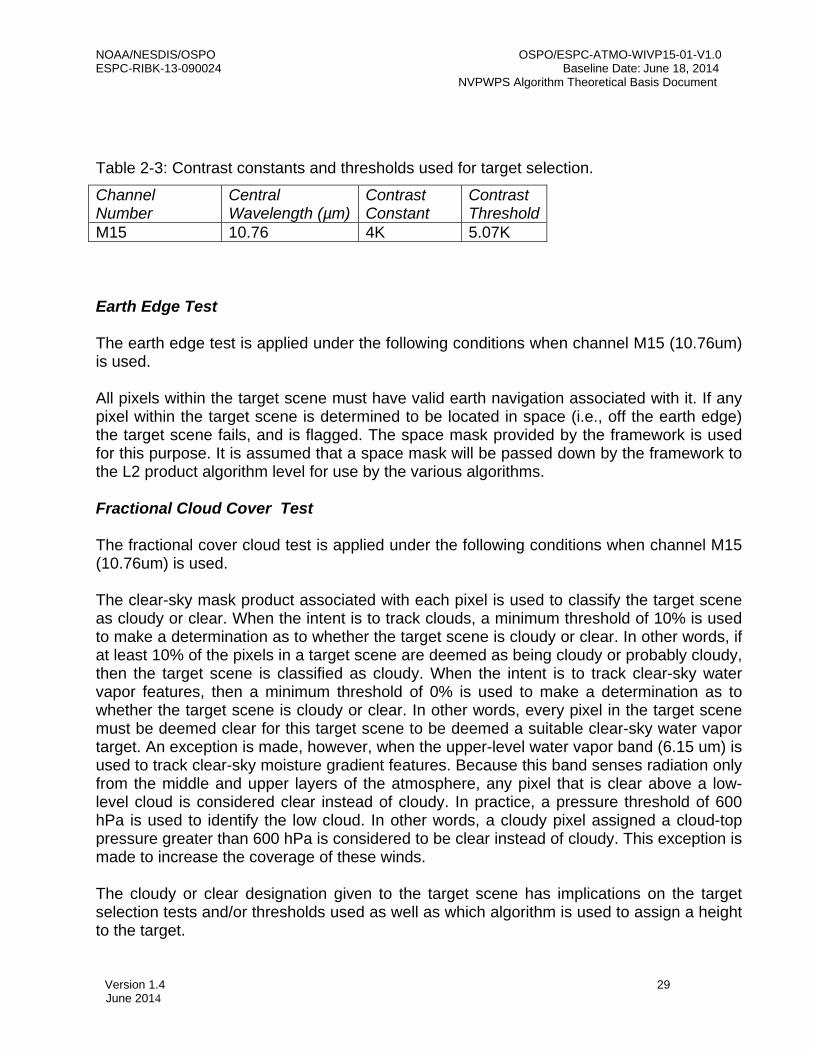
Table 2-3: Contrast constants and thresholds used for target selection.
Channel Number
Central Wavelength (µm)
Contrast Constant
Contrast Threshold
M15 10.76 4K 5.07K Earth Edge Test The earth edge test is applied under the following conditions when channel M15 (10.76um) is used. All pixels within the target scene must have valid earth navigation associated with it. If any pixel within the target scene is determined to be located in space (i.e., off the earth edge) the target scene fails, and is flagged. The space mask provided by the framework is used for this purpose. It is assumed that a space mask will be passed down by the framework to the L2 product algorithm level for use by the various algorithms. Fractional Cloud Cover Test The fractional cover cloud test is applied under the following conditions when channel M15 (10.76um) is used. The clear-sky mask product associated with each pixel is used to classify the target scene as cloudy or clear. When the intent is to track clouds, a minimum threshold of 10% is used to make a determination as to whether the target scene is cloudy or clear. In other words, if at least 10% of the pixels in a target scene are deemed as being cloudy or probably cloudy, then the target scene is classified as cloudy. When the intent is to track clear-sky water vapor features, then a minimum threshold of 0% is used to make a determination as to whether the target scene is cloudy or clear. In other words, every pixel in the target scene must be deemed clear for this target scene to be deemed a suitable clear-sky water vapor target. An exception is made, however, when the upper-level water vapor band (6.15 um) is used to track clear-sky moisture gradient features. Because this band senses radiation only from the middle and upper layers of the atmosphere, any pixel that is clear above a low-level cloud is considered clear instead of cloudy. In practice, a pressure threshold of 600 hPa is used to identify the low cloud. In other words, a cloudy pixel assigned a cloud-top pressure greater than 600 hPa is considered to be clear instead of cloudy. This exception is made to increase the coverage of these winds. The cloudy or clear designation given to the target scene has implications on the target selection tests and/or thresholds used as well as which algorithm is used to assign a height to the target.

NOAA/NESDIS/OSPO OSPO/ESPC-ATMO-WIVP15-01-V1.0 ESPC-RIBK-13-090024 Baseline Date: June 18, 2014 NVPWPS Algorithm Theoretical Basis Document
Version 1.4 30 June 2014
Channel Validity Test The channel validity test is applied under the following conditions when channel M15 (10.76um) is used. The channel brightness temperature of each pixel in a target scene is checked to ensure its value falls within a valid range. For the IR channels, the valid range of brightness temperature is 150-340K. If the channel brightness temperature of any pixel in the target scene falls outside the valid range the target fails and is flagged. Spatial Coherence Test The spatial coherence test is applied under the following conditions:
• When channel M15 (10.76um) is used • Target scene has been classified as cloudy
Originally proposed by Coakley and Bretherton (1982), the spatial coherence method utilizes the local spatial structure (local mean and standard deviation) of the IR-window radiance field to determine the radiances associated with cloud-free and completely cloud-covered fields of view and to infer the radiances associated with partially filled fields of view. In the context of the DMW algorithm, the method is first used to filter out target scenes that are too uniform to track reliably, and second, to filter out scenes that may contain multiple cloud layers. For both purposes it is necessary to compute the local mean and standard deviation of the radiance field derived from 3x3 sub-regions within the larger target box. The mean and standard deviation values are computed for the entire line segment (with data surrounding the target box). Near the edges these values are computed with however many pixels are available. After computing the mean and standard deviation radiance values for all possible 3x3 pixel sub-regions in the target box, a standard deviation threshold (1.0 Wm-2 sr-1 um-1) is applied that results in a “filtered” or coherent sample. The standard deviation threshold value is chosen arbitrarily with consideration given to the range of possible data values expected in the imagery. The resulting “filtered” or coherent sample represents either cloud-free or completely cloud-covered pixels from the less-coherent sample that is likely to include partially filled fields of view. If more than 80% of the total number of 3x3 pixel sub-regions within the target scene have a standard deviation below the defined threshold, the scene is deemed to be too coherent and it fails to be a viable target for subsequent feature tracking. Target scenes that contain a mixture of cloud-free and cloud-covered pixels exhibit a characteristic arch shape as shown in Figure 2-5. Multi-Layer Cloud Test The multi-layer cloud test is applied under the following conditions:

NOAA/NESDIS/OSPO OSPO/ESPC-ATMO-WIVP15-01-V1.0 ESPC-RIBK-13-090024 Baseline Date: June 18, 2014 NVPWPS Algorithm Theoretical Basis Document
Version 1.4 31 June 2014
• When channel M15 (10.76um) is used • Target scene has been classified as cloudy
Target scenes that contain multiple cloud layers in them can be difficult to track since clouds at different levels of the atmosphere may be moving in different directions and/or speeds. Furthermore, the assignment of a representative cloud height in these situations is difficult given the existence of clouds at different levels of the atmosphere. In order to avoid these troublesome target scenes, the filtered sample from the spatial coherence approach described above is used in a cluster analysis approach in order to identify the possible existence of multiple cloud layers. The basic idea behind the method is to use the local mean and standard deviation information to identify clusters of points sharing common characteristics (such as mean radiance and low variance). If more than two clusters (one of which is implicitly assumed to be the surface in clear sky conditions) is found in a target box then the scene is rejected. The key concept of this approach is that peaks in the frequency histogram can be described by Gaussian distribution functions (Simmer et al., 1982; Rossow et al., 1985; Nieman et al., 1993). Using the filtered sample, the method starts by identifying the peak in the 1-D histogram of local mean IR radiance values. A Gaussian curve is then fitted to the peak of the histogram and all points falling within +/- 3 standard deviations of the peak value are added to the dominant cluster sample. Likewise, a second Gaussian is fitted to the “cold peak” of the histogram and the cold cluster is identified. Lastly, the total number of points falling within the dominant and cold clusters is summed and compared to the total number of points in the filtered sample. If the total number of points from both clusters is less than 80% of the original filtered sample it is assumed that a third, unidentified, cluster exists (in theory representing another cloud layer) and the target is rejected. The example shown in Figure 2-6 is for a target scene that was partly filled by a single cloud layer.

NOAA/NESDIS/OSPO OSPO/ESPC-ATMO-WIVP15-01-V1.0 ESPC-RIBK-13-090024 Baseline Date: June 18, 2014 NVPWPS Algorithm Theoretical Basis Document
Version 1.4 32 June 2014
The step by step procedure for the above procedure is defined below:
• Construct histogram of radiance values from 0 to 199 using bin width of 1.
• Estimate the variance using a two point method (one end point is always the peak frequency) for the three bins closest to the peak (Note: if there are multiple peaks with the same count the first peak is selected) on the LHS with the formula:
(5)
Where x is the bin value (i.e., radiance), f is the number of points in the bin (i.e., frequency),
𝑥𝑖 = 𝑥𝑖−1+𝑥𝑖
2 (6)
and
𝑥𝑝𝑒𝑎𝑘 = 𝑥𝑝𝑒𝑎𝑘−1+𝑥𝑝𝑒𝑎𝑘2
(7)
NOTE: If fi is 0 then the variance is set to a value of 0.
• Average the three variance estimates to obtain the final variance for the LHS half
curve.
𝑣𝑎𝑟𝑖𝑎𝑛𝑐𝑒𝐿𝐻𝑆 = 13∑ 𝑣𝑎𝑟𝑖𝑎𝑛𝑐𝑒𝑖3𝑖=1 (8)
Figure 2-5. Scatter diagram of window channel IR local mean radiance and standard deviation values for a single target scene. Each point in the figure represents a 3x3 array of pixels constructed from 4-km GOES IR radiance data. The cluster of points near 80 is ass

NOAA/NESDIS/OSPO OSPO/ESPC-ATMO-WIVP15-01-V1.0 ESPC-RIBK-13-090024 Baseline Date: June 18, 2014 NVPWPS Algorithm Theoretical Basis Document
Version 1.4 33 June 2014
NOTE: If the computed variance is greater than 25 it is set to a value of 25. Also, only non-zero variance values are used to compute the average. This implies any bin having a zero count will not be used in the average.
• Repeat steps 2 and 3 for the three bins closest to the peak on the RHS of peak frequency.
• Compute the full Gaussian curve using LHS and RHS variance values. The full Gaussian spans the interval ±5 standard deviations about the peak frequency and is computed using:
𝑓𝐺𝑎𝑢𝑠𝑠 = 𝑓𝑝𝑒𝑎𝑘𝑒𝑥𝑝 �−�𝑥𝑖−𝑥𝑝𝑒𝑎𝑘�
2
2�𝑣𝑎𝑟𝑖𝑎𝑛𝑐𝑒𝐿𝐻𝑆,𝑅𝐻𝑆�� (9)
NOTE: If the exponent is less than -10.0 it is set to a value of 0.0.
• Find peak frequency of 5 coldest non-zero clusters and repeat steps 2 to 5 for the cold peak.
• Total the number of pixels engulfed by the two Gaussian curves according to the following rules:
±1 standard deviation of peak, sum up all histogram points ±1to3 standard deviations of peak, sum up points in Gaussian histogram (from step 5) Do not count pixels outside this range
• If the total number of points from both clusters is less than 80% of the original filtered
sample, it is assumed that a third, unidentified cluster, exists and the target scene is flagged. DMWA assigns QC_Flag=6 to the processed target scene and moves to the next target scene.
• Note: If the cold peak corresponds with the overall peak this suggests a single cloud layer is present in the target scene. This would be an acceptable target.

NOAA/NESDIS/OSPO OSPO/ESPC-ATMO-WIVP15-01-V1.0 ESPC-RIBK-13-090024 Baseline Date: June 18, 2014 NVPWPS Algorithm Theoretical Basis Document
Version 1.4 34 June 2014
Figure 2-6. Histogram plots of local mean infrared radiance values for a single target scene: (Left) For the entire target scene, (Right) Filtered sample with Gaussian curves fitted to the peaks. The peak on the left is associated with a single cloud layer. 2.3.2.2 Feature Tracking Correlation-based methods are commonly used to track cloud and clear-sky water vapor features in image sequences. A widely used correlation approach to feature tracking is the Sum of Squared Differences (SSD). This correlation method, like all others, aims to locate a target scene, at some time t, in a larger search scene at some earlier or later time. This process is illustrated in Figure 2-7. A similarity criterion is computed that measures the correlation between the target and search area pixel scenes in the two images. In the DMW algorithm a feature or target is selected from the middle of three images and is tracked backwards and forwards in time, thus generating two displacements. These two displacements are then averaged to generate an average wind vector that is taken to

NOAA/NESDIS/OSPO OSPO/ESPC-ATMO-WIVP15-01-V1.0 ESPC-RIBK-13-090024 Baseline Date: June 18, 2014 NVPWPS Algorithm Theoretical Basis Document
Version 1.4 35 June 2014
Figure 2-7. Schematic showing the basic concepts associated with the feature tracking algorithm. Targets are selected from the middle image of a three-image loop and tracked forward and backward in time via the SSD method. The two displacements are averaged. represent the motion of the target over the time interval spanned by the image triplet. This average vector is assigned to the middle image target location. This approach is what we will refer to as the conventional feature tracking approach. When tracking cloud features involving the VIIRS M15 band (10.76um an approach referred to as nested tracking (Daniels and Bresky, 2010) is used. Nested tracking uses the SSD method to compute local motions nested within a larger target scene together with a clustering algorithm, to arrive at a superior motion solution for the larger target scene. The details of this approach are described below in Section 2.3.2.2.2. A short term GFS model forecast wind is used in the feature tracking step to center the location of the search area in the other images. This is done for two reasons. First, it minimizes computational time required for tracking and secondly, minimizes the number of false solutions generated by the SSD method. It should be emphasized that the search region must be sufficiently large to allow for substantial departures from the forecast. It has been shown by Merrill (1989) that the derived wind is inherently constrained to the forecast wind by the following relationship:
txLuu g 2
)2()( −≤− (10)

NOAA/NESDIS/OSPO OSPO/ESPC-ATMO-WIVP15-01-V1.0 ESPC-RIBK-13-090024 Baseline Date: June 18, 2014 NVPWPS Algorithm Theoretical Basis Document
Version 1.4 36 June 2014
where u (m/s) is the east-west component of the satellite wind, ug (m/s) is the east-west component of the forecast wind, L is referred to as the lag size and is the max displacement of a target scene within a given search box, t is the time interval (in seconds) between images and x is the resolution of the imagery in meters. A similar relationship holds for the north-south component, but is omitted for brevity. For a given image sequence time interval and pixel resolution, the ratio given by the right hand side of equation (10) yields a value that represents the maximum departure of the feature tracking wind solution from the forecast wind. It is important that this ratio be sufficiently large to minimize the dependency of the forecast wind in the tracking step. Furthermore, the magnitude of this ratio must be considered when different size target scenes and/or sequence time intervals are used. For example, for a given image resolution, if smaller image time intervals are desired, then a corresponding reduction in the lag size must be made in order to keep the magnitude of the ratio constant. By specifying a maximum forecast departure of 30 m/s in Equation (10), the equation for keeping the lag size constant is given by:
Ltx
=+ 260 (11)
By specifying the desired time interval between images to use and the resolution of the imagery in Equation 11), the lag size can be computed. Once the lag size is known, the size of the search scene can be computed from:
S = T + L - 1 (12)
Where: S is the search scene size in pixels T is the target scene size in pixels L is the lag size in pixels
In summary, the step-by-step procedure for tracking is as follows:
1. Compute forecast displacement, in pixels, using the forecast wind valid at the target lat/lon and interpolated to the initial height estimate.
2. Use forecast displacement to center search box. 3. Fill search box with data from image buffer 4. Find matching scene in the first and third images and compute AMV displacement
via the conventional or nested tracking algorithm (displacement is a real value not an integer value).
5. Compute end point of AMV displacement vector in pixel coordinates 6. Compute earth location (lat/lon) of end point 7. Compute U/V components using the beginning (target center pixel) and ending
(match location) lat/lon values
2.3.2.2.1 Sum-of-Squared Difference Method

NOAA/NESDIS/OSPO OSPO/ESPC-ATMO-WIVP15-01-V1.0 ESPC-RIBK-13-090024 Baseline Date: June 18, 2014 NVPWPS Algorithm Theoretical Basis Document
Version 1.4 37 June 2014
(Euclidean Distance) The sum-of-squared-differences method (SSD) is the correlation routine used by the DMW algorithm. In the SSD routine the following sum is minimized:
2
2,
1 )],(),([ yxIyxIyx
−∑ (13)
where I1 is the brightness temperature at pixel (x,y) of the target scene, I2 is the brightness temperature at pixel (x,y) of the search window, and the summation is performed over two dimensions. In practice, the region over which the search is conducted is substantially larger than the size of the target scene and the above summation is carried out for all target box positions within the search region. The array of positions that the target box can assume in the search region is often referred to as the “lag coefficient” or “lag” array and the field of values is referred to as the correlation surface. The size of the search and lag arrays are given by Equations (11) and (12) in the previous section. To speed up the search for the minimum SSD value, the tracking algorithm first constructs a table (a square array) of values specifying the order of positions to search within the lag matrix. This is illustrated in Figure 2-8. The first point in the table corresponds with the middle of the lag matrix, which also corresponds with the center of the search region, which also corresponds with the location predicted by the forecast. The search then “spirals” outward in a clockwise fashion about the central point. By starting the search in the middle of the search region we are hopefully maximizing our chance of finding a match sooner than if we were to start in the top left corner of the search region. The spiral search, when used in conjunction with the practice of terminating the SSD summation early once a current minimum has been exceeded, can significantly reduce the number of computations required during the tracking step of the DMW algorithm. A typical correlation surface for the SSD method using 4km IR observations is shown in Figure 2-9. Each pixel in this figure represents a SSD value for a potential matching scene in the search region. The cool colors (blues) indicate minimum values while the warm colors (yellows) indicate relative maxima. The minimum SSD solution value results in a discrete, pixel displacement being identified as a possible DMW tracer. Unaltered, these integer displacements would cause an artificial binning of the satellite derived wind estimates. To avoid this effect, the SSD values of the four points surrounding the minimum SSD are used to linearly interpolate to sub-pixel accuracy.
7 8 9 10

NOAA/NESDIS/OSPO OSPO/ESPC-ATMO-WIVP15-01-V1.0 ESPC-RIBK-13-090024 Baseline Date: June 18, 2014 NVPWPS Algorithm Theoretical Basis Document
Version 1.4 38 June 2014
6 1 2 11
5 4 3 12
13
Figure 2-8. Table (a square array) of values specifying the order of positions to search within the lag matrix as part of the spiral search algorithm. The following equation is used to compute the fractional element displacement:
𝛥 = (𝑙1−𝑙3)2(𝑙1+𝑙3−2𝑙2)
(14) where l_1 is the lag array value at (x-1, y), l_2 is the lag array value at (x, y) (i.e., the minimum SSD value) and l_3 is the lag array value at (x+1, y). The fractional value is added to the integer displacement to produce a Real (ie., non-integer) estimate of the displacement.. A similar equation is used for the fractional line displacement, but it uses the lag array values above (x, y-1) and below (x, y+1) the minimum lag location.

NOAA/NESDIS/OSPO OSPO/ESPC-ATMO-WIVP15-01-V1.0 ESPC-RIBK-13-090024 Baseline Date: June 18, 2014 NVPWPS Algorithm Theoretical Basis Document
Version 1.4 39 June 2014
Figure 2-9. Example of a typical correlation surface for the Sum-of-Squared Difference (SSD) tracking method for 4km infrared imagery. The cool (blue) colors indicate minimum values while the warm (yellows) colors indicate relative maxima.
2.3.2.2.2 Nested Tracking When tracking cloudy target scenes using VIIRS M15 (10.76um), a technique referred to as “nested tracking” is employed. This approach involves nesting smaller (5x5 pixels) target scenes within a larger target scene (ie., whose size is specified in Table 2-1) so that a field of local motion vectors can be derived over the interior pixels. A schematic of this approach is shown in Figure 9 alongside one example of the vector field produced by the approach. Differences in orientation and magnitude can arise between the local motion vectors if more than one cloud layer is being tracked or if multiple scales of motion are being detected. Outliers vectors – those vectors that differ greatly from most of the sample – can result if the cloud is evolving or if the smaller box is insufficiently large to resolve the true motion. The second contributor to vector outliers is often referred to as the aperture effect and is discussed at length in the field of computer vision (Trucco and Verri, 1998). The red vector shown in Figure 2-10 makes it clear that averaging conflicting motions within a target scene can produce a slow motion estimate. The challenge is to derive a dominant motion vector from a subset of all possible solutions that best represents the flow of the larger target scene. This can be accomplished by analyzing all of the local displacements within the larger target scene with a cluster analysis program. More specifically, a cluster analysis of the line and element displacements is done to produce clusters that represent unique displacements.
Figure 2-10. Schematic of the nested tracking approach. The white vectors show the local motion vectors successfully derived for each possible 5x5 box within a larger 15 x 15 target

NOAA/NESDIS/OSPO OSPO/ESPC-ATMO-WIVP15-01-V1.0 ESPC-RIBK-13-090024 Baseline Date: June 18, 2014 NVPWPS Algorithm Theoretical Basis Document
Version 1.4 40 June 2014
scene. The red vector on the right is the resulting motion vector if one were to take an average of all the successfully derived local motion vectors.
The justification for using a cluster analysis algorithm to analyze the local motion field is twofold. First, as was discussed above, the local motion field can be quite noisy. The field of vectors often reveals motion associated with two or more cloud layers and/or spatial scales. Removing noise and separating the sample into coherent motion clusters can prevent the excessive averaging of motion occurring at multiple levels or for different scales that can lead to a slow speed bias. Second, identifying clusters in the local motion field provides a means for directly linking the tracking step with the height assignment step. In other words, the pixels belonging to the coherent clusters allow us to limit the sample of pixels used for height assignment. For the DMW algorithm we selected a cluster analysis program called DBSCAN (Ester et. al., 1996), a density based algorithm for identifying clusters in spatial databases with noise. It was selected because it is very effective at identifying clusters of varying shapes and, unlike other methods such as K-means (Lakshmanan et al., 2009a, 2009b, 2003), does not require the user to specify apriori the number of clusters to find. Two parameters must be specified before running DBSCAN: the minimum number of points in a cluster (currently set at 4) and the radius around the point to search for neighbors in the cluster (currently set at 0.5 pixels). Basically, DBSCAN steps through each point (each point being a displacement in line and element space) and classifies it in one of three ways. A “core” cluster point has at least 4 neighbors within its neighborhood (radius). A boundary point has fewer than 4 neighbors but is still connected to a cluster by at least one other point. The third possibility is that the point does not belong to any cluster and is “noise.” Output from DBSCAN consists of a list of clusters found and the number of points in each cluster. One example of output from DBSCAN is shown in Figure 2-11. This figure shows that noisy motions have been removed from the scene leaving two distinct motion clusters. The DMW algorithm selects the largest cluster to represent the dominant motion and computes a final derived motion vector by averaging the displacements belonging to the largest cluster. Figure 2-12 shows the vector field that remains after the analysis is complete.

NOAA/NESDIS/OSPO OSPO/ESPC-ATMO-WIVP15-01-V1.0 ESPC-RIBK-13-090024 Baseline Date: June 18, 2014 NVPWPS Algorithm Theoretical Basis Document
Version 1.4 41 June 2014
Figure 2-11. Motion clusters identified by DBSCAN clustering routine. Green dots indicate line and element displacements belonging to the largest cluster. Red dots indicate line and element displacements belonging to the second largest cluster. Blue dots represent
Figure 2-12. Example of the vector field produced with nested tracking before (left) and after (right) DBSCAN is applied to find the largest cluster. The forecast vector (blue) is shown for comparison.
2.3.2.2.3 Feature Tracking Gross Error Tests

NOAA/NESDIS/OSPO OSPO/ESPC-ATMO-WIVP15-01-V1.0 ESPC-RIBK-13-090024 Baseline Date: June 18, 2014 NVPWPS Algorithm Theoretical Basis Document
Version 1.4 42 June 2014
All retrieved wind values undergo a series of quality control tests to determine if the derived wind is valid. This series of tests are described below. If a retrieved wind fails any one of these tests, it is deemed to be an invalid wind and is flagged appropriately. Each failure is associated with a unique “flag” value which is saved in the DMW output file. These unique flag values are listed in Table 6. The tests are applied in the following order:
a. Match on boundary check b. Correlation check c. u-component acceleration check d. v-component acceleration check e. u- and v-component acceleration check f. Slow wind speed check g. Channel-specific NWP wind speed and direction comparison tests
Correlation Test As mentioned in Section 2.1, one of two correlation tests is applied when matching the feature of interest to the original target scene. When nested tracking is employed, each matching 5x5 sub-scene must have a correlation score of 0.8 or higher. Otherwise, the displacement associated with the match is discarded and will not be analyzed by the cluster analysis routine. When conventional tracking is used instead of nested tracking, a lower threshold of 0.6 is applied. In this case, the correlation scores of each of the intermediate (i.e., the reverse and forward) matching scenes (derived from the SSD method described in Section 2.3.2.2.1) are checked to see if they exceed the minimum threshold value of 0.60. If either scene fails this correlation test, the DMW product is flagged as unacceptable in the output file. A higher correlation threshold is used for nested tracking because the scene being matched is much smaller and this increases the likelihood of finding a false positive. The higher threshold is a way of accounting for the higher variance in the estimated displacement and is used to remove gross errors from the matching process. . u/v-acceleration Test If the DMWA is performing as intended, it is reasonable to expect that the wind estimates derived from each image pair of the image triplet will be similar to one another. While real accelerations are certainly plausible, especially in certain weather regimes (near jet streams, for example) testing for unrealistic accelerations is prudent, especially given the time and space scales we are concerned with. The existence of an unrealistic acceleration in either the u-component or v-component of the DMW is likely to be the result of a false positive in the tracking step. Large, unrealistic u- or v-accelerations are dealt with by imposing an upper limit of 10 m/s on the difference between the two individual u and v- components of DMWs derived for any of the spectral channels except the visible channel, where a 5 m/s limit is imposed. Any DMW that fails the u/v acceleration test is flagged.

NOAA/NESDIS/OSPO OSPO/ESPC-ATMO-WIVP15-01-V1.0 ESPC-RIBK-13-090024 Baseline Date: June 18, 2014 NVPWPS Algorithm Theoretical Basis Document
Version 1.4 43 June 2014
Slow Wind Speed Test The speed of every DMW is checked against a minimum speed threshold of 3 m/s. If any DMW is slower than this speed threshold, then the DMW is flagged. Correlation Boundary Test If either of the intermediate matching scenes derived from the SSD method described in Section 2.3.2.2.1 are found on the boundary of the search scene, then the match scene is flagged. This condition may indicate the true matching solution is located beyond the domain of the search scene. In terms of the lag array, this implies that the tracer is rejected if the minimum SSD value is found along the edges of the lag array. Likewise, when nested tracking is used, any matches found on the boundary of the lag array are discarded from influencing the dominant motion calculation. It should be noted that when tracking the entire target scene with the conventional approach, the correlation boundary test results in a failed tracer. This is not true when nested tracking is employed. In this case, the match is rejected, and the algorithm moves to the next pixel where it attempts to compute another local motion vector. In other words, the small 5x5 sub-target is discarded, not the entire target scene.
NWP Wind Speed and Direction Comparison Tests Several empirical gross error tests that compare the DMW speeds and directions to the corresponding wind speeds and directions obtained from a short-term NWP forecast have been developed over the years and incorporated into the current operational DMWA used for GOES, Moderate Resolution Imaging Spectroradiometer (MODIS), and AVHRR winds. These various tests have been adopted for the DMWA and are summarized in Table 2-4. These gross error tests serve as a defense against DMWs that have been assigned incorrect heights. As noted previously, the height assignment process itself may, from time to time, introduce substantial errors. For example, tracers in very thin cirrus are often assigned too low in the atmosphere resulting in a large fast bias. One way to identify such winds is to use a short-term forecast from a global model and look for large differences between the two wind estimates. If a DMW fails any of these tests, then the DMW is flagged. The test thresholds are intentionally set to broad values so that only gross differences from the first guess will be captured and flagged, in case the forecast itself is erroneous. More elaborate QC schemes to identify the likely quality of each DMV are imposed following these gross error checks, and are described in detail in the next sections.

NOAA/NESDIS/OSPO OSPO/ESPC-ATMO-WIVP15-01-V1.0 ESPC-RIBK-13-090024 Baseline Date: June 18, 2014 NVPWPS Algorithm Theoretical Basis Document
Version 1.4 44 June 2014
Table 2-4: Summary of the DMW gross error quality control tests performed.
Satellite Channel
DMW Height Criteria
Speed Criteria for Applying
Test
Test
M15 (10.76um)
>=500 hPa
Forecast
speed > 0.5 m/s OR
AMV speed >= 11 m/s
Directional departure from forecast >= 500
Speed difference
between DMW and forecast wind > 8 m/s
Note: The directional departures described in Table 2-4 are absolute directional departures having a maximum value of 180 degrees.
2.3.2.3 Target Height Assignment Each suitable target (i.e., those passing all of the target selection tests described in Section 2.3.2.1.1) is assigned a height using information from the middle image of the loop sequence. The cloudy or clear designation for each target scene (per the fractional cloud cover test described in Section 2.3.2.1.1) has implications on how a representative height assignment is computed for each target scene. The process of assigning a representative height to the DMW tracer involves selecting the appropriate sample of pixels from the target scene and using these pixels to compute a representative height for the target scene being processed. The following factors drive the selection of the appropriate sample of pixels to use, as well as the approach, to compute a representative height for each target:
• Target is deemed clear or cloudy • Channel used to derive the wind • Whether or not the nested tracking methodology is used
Cloudy Target Scenes When the VIIRS M15 channels (10.76um) is used to track cloudy target scenes, pixel-level cloud-top pressures provided by the upstream cloud-top height algorithm (see GOES-R ABI Cloud Height ATBD [Heidinger, 2010] for details) are used to compute a representative height for the target scene. Since the nested tracking approach is used when using these channels, only cloud-top pressures associated with pixels belonging to the largest cluster (as defined in the nested tracking discussion in Section 2.3.2.2.2) are used to derive a representative height. Because two unique large clusters are identified – one for the reverse time step and one for the forward time step – the cloud-top pressure samples from

NOAA/NESDIS/OSPO OSPO/ESPC-ATMO-WIVP15-01-V1.0 ESPC-RIBK-13-090024 Baseline Date: June 18, 2014 NVPWPS Algorithm Theoretical Basis Document
Version 1.4 45 June 2014
both of these clusters are combined and the median cloud-top pressure value is assigned as the representative height for this target. A key benefit of this approach is that the assigned height is inherently linked to the tracking solution since the same sample of pixels contributes to each of these derived quantities. Figure 2-13 highlights the fact that this approach will usually produce a lower height assignment in the atmosphere (higher pressure) than the traditional method of assigning the height based on an arbitrary cold sample (typically 20%) of pixels.
Figure 2-13. Cloud-top pressure distribution for a single target scene. The values associated with the largest cluster are shown in green. In situations where a low level cloudy target scene over ocean is partially or totally located in an area experiencing a low level temperature inversion, the DMWA must apply a different approach to compute a representative height assignment to the target scene. Low-level temperature inversions occur frequently over the ocean in the vicinity of the subtropical high where large-scale subsidence contributes to their formation. These regions are often covered by extensive sheets of marine stratocumulus cloud located at the base of the temperature inversion (see Figure 2-14). Cloud height algorithms often overestimate the height of these cloud layers by 200 hPa or greater (Gustafsson and Lindberg, 1999). The problem arises when there are two elevations in the temperature profile at which the cloud temperature is reached. In this scenario the actual cloud layer is found at the bottom of the inversion. The DMWA uses the low-level temperature inversion flag output by the cloud height algorithm to identify those pixels in a target scene where a low level temperature inversion is present. In these situations, the DMWA keeps track of pixels within the largest nested tracking clusters, whose heights are derived at the base of the inversion versus those derived radiometrically via the cloud height algorithm. The DMWA uses only the cloud heights (pressures) belonging to the larger of these two samples to assign a height to the

NOAA/NESDIS/OSPO OSPO/ESPC-ATMO-WIVP15-01-V1.0 ESPC-RIBK-13-090024 Baseline Date: June 18, 2014 NVPWPS Algorithm Theoretical Basis Document
Version 1.4 46 June 2014
derived wind. The representative height assigned to the derived motion wind is the median pressure of the larger sample. Figure 2-14. Idealized temperature profile highlighting the cloud height assignment problem posed by low-level temperature inversions. Initial Cold Sample Height Regardless of whether nested tracking or traditional tracking is being used an initial “cold sample” height assignment must be computed. The primary purpose of computing an initial height is to use it as a look up index to obtain the forecast wind from a profile. The forecast wind is subsequently used to center the search box in the subsequent (or previous) image. A 1-D histogram of cloud top temperatures (CTT) is constructed in the following manner:
Loop through each pixel in the target scene and check the cloud mask, CTT and low-level inversion flag and retain all pixels having a valid cloud top pressure (i.e., not missing). Next, check that the temperature value is in the range 150 – 340 K and exclude those outside of the range. Lastly, determine how many pixels are located in a low-level inversion region (low-level inversion flag=1) and how many pixels are outside a low-level inversion region (low-level inversion flag=0). Determine which sample is larger. Using the larger sample a histogram is constructed for the range 150 K – 340 K. With a scale factor of 10 the range of the histogram is actually 1500 – 3400. Each CTT from the larger sample is placed in a slot on the histogram rounding up or down to the nearest bin. A point cutoff is computed using the cold threshold: Point_Cutoff = NINT(REAL(Histogram_Points) * Cold_Threshold) where ‘Histogram_Points’ is the size of the screened sample from step 1 and Cold_Threshold is 0.25.

NOAA/NESDIS/OSPO OSPO/ESPC-ATMO-WIVP15-01-V1.0 ESPC-RIBK-13-090024 Baseline Date: June 18, 2014 NVPWPS Algorithm Theoretical Basis Document
Version 1.4 47 June 2014
Starting from the cold end scan the histogram to find the cutoff slot. One of three conditions must be met: threshold_loop: DO BrtTemp = Lower_Bound, Upper_Bound Cold_Sample = Cold_Sample + Histogram(BrtTemp) IF (Histogram(BrtTemp) .GT. 0) Number_Of_Bins = Number_Of_Bins + 1 IF (Cold_Sample .GT. Point_Cutoff .AND. Number_Of_Bins .GT. 1) THEN Cold_Sample = Cold_Sample - Histogram(BrtTemp) Cold_Slot_Threshold = BrtTemp - 1 EXIT ! Keep at least one histogram bin ELSE IF (Cold_Sample .GT. Point_Cutoff .AND. Number_Of_Bins .EQ. 1) THEN Cold_Sample = Cold_Sample Cold_Slot_Threshold = BrtTemp EXIT ELSE IF (Cold_Sample .LE. Point_Cutoff .AND. BrtTemp .EQ. Upper_Bound) THEN Cold_Sample = Cold_Sample Cold_Slot_Threshold = BrtTemp EXIT ENDIF END DO threshold_loop Cold sample arrays of CTT, cloud top pressure and cloud top height are created using the cold slot threshold as the highest value allowed.
2.3.2.3.1 Height Assignment Quality Tests All retrieved wind height (in pressure) values undergo a couple of quality control tests to determine if the derived heights are valid. These tests are described below. If a retrieved height fails any one of these tests, it is deemed to be invalid and is flagged appropriately. Each failure is associated with a unique “flag” value which is saved in the DMW output file. These unique flag values are also listed in Table 5. Acceptable Height Assignment Check An acceptable height assignment check is done for each derived motion wind that is attempted. The derived height is checked to determine if it falls within an acceptable height (in pressure) range. The minimum and maximum pressures belonging to this range are a function of which channel is being used to derive the wind and shown in Table 2-5.

NOAA/NESDIS/OSPO OSPO/ESPC-ATMO-WIVP15-01-V1.0 ESPC-RIBK-13-090024 Baseline Date: June 18, 2014 NVPWPS Algorithm Theoretical Basis Document
Version 1.4 48 June 2014
Table 2-5: Acceptable height range to use as a function of channel used and tracer type
Channel Number
Tracer Type
Central Frequency (µm)
Acceptable Height
Range (hPa) M15 Cloud-top 10.76 100 - 1000
Height Consistency Check When nested tracking is performed, a height consistency checked is performed between the median pressure computed from the largest cluster belonging to the first and second image pairs, respectively. If the difference in these two pressures exceeds 100 hPa, then the derived motion wind is flagged as bad. 2.3.2.4 Product Quality Control Quality control of the retrieved DMWs is performed in two ways. The first is through the application of target selection, feature tracking, and height assignment error checks as described in the previous sections. The second way involves the calculation of two quality indicators for each of the DMWs using two different, but related, algorithms: the Quality Indicator (QI) (Holmlund, 1998; Holmlund et al., 2001) and the Expected Error (EE) (LeMarshall et al., 2004; Berger et al. 2008). 2.3.2.4.1 Quality Indicator (QI) Method The statistically-based quality indicator (QI) developed at EUMETSAT estimates the reliability of each derived DMW based on several quality control tests (Holmlund, 1998, Holmlund et. al 2001). These tests not only analyze the consistency in space and time of each of the intermediate DMW vector components, but also the height and temperature of the tracers used in the vector determination, the symmetry of vector pairs achieved from tracking tracers between consecutive images, differences with surrounding vectors, and differences from a forecast field (optional). There are a total of seven individual components that contribute to the final QI score that is appended to each DMW. A weighted average value is computed for the final quality test function value fi(x) for each vector. In order to combine the results of the different test functions, each result must be normalized into a specific range. This is done using a tanh-based function:
φi x( )=1− tanh fi x( )[ ]{ }ai
(15)

NOAA/NESDIS/OSPO OSPO/ESPC-ATMO-WIVP15-01-V1.0 ESPC-RIBK-13-090024 Baseline Date: June 18, 2014 NVPWPS Algorithm Theoretical Basis Document
Version 1.4 49 June 2014
After normalization of all of the tests, QI values will be distributed from zero (poor quality) to one (perfect quality). Direction Consistency Check This calculation is a measure of the direction consistency of the DMW. A quality tracer should provide sub-vectors that are similar in direction. In function space it is calculated as: Direction:
| D2(x,y) − D1(x,y) | / A * exp−((V2 (x,y )+V1 (x,y ))/ B )+C ) (16) Di(x, y), Vi(x, y) are the direction (degrees) and speed (m/s) derived from the first image (i = 1) pair (image 1 and image 2) or the second imager (i = 2) pair (image 2 and image 3) of an image triplet at location (x, y). The normalized component used in the software is constructed as such: QIdir = 1 – (tanh(|D2(x, y)-D1(x, y)|/(A*exp(-vel/B)+C)))**D (17) Where: vel = (V1(x, y) + V2(x, y))/2 The values of the constants are: A 20 B 10 C 10 D 4 Speed Consistency Check This calculation is a measure of the speed consistency of the DMW. Intermediate DMWs should show agreement in speed. In function space it is calculated as: Speed: |V2(x, y)-V1(x, y)|/(A*(V2(x, y)+(V1(x, y))+B) (18) Vi(x, y) is the speed (m/s) derived from the first image (i = 1) pair (image 1 and image 2) or the second image (i = 2) pair (image 2 and image 3) of an image triplet at location (x, y). The normalized component used in the software is constructed as such: QIspd = 1 – (tanh(|V2(x, y)-V1(x, y)|/(A*vel+B)))**C (19) Where:

NOAA/NESDIS/OSPO OSPO/ESPC-ATMO-WIVP15-01-V1.0 ESPC-RIBK-13-090024 Baseline Date: June 18, 2014 NVPWPS Algorithm Theoretical Basis Document
Version 1.4 50 June 2014
vel = (V1(x, y) + V2(x, y))/2 The values of the constants are: A 0.2 B 1.0 C 3.0 Vector Consistency Check This calculation is a measure of the vector consistency of the DMW. This test looks at the vector pairs that make up the final DMW. It should reject acceleration errors, but allow for real acceleration changes (jet entrance and exit regions). In function space it is calculated as: Vector: |S2(x, y)-S1(x, y)|/(A*(V2(x, y)+(V1(x, y))+B) (20) Si(x, y) is the vector (m/s) derived from the first image (i = 1) pair (image 1 and image 2) or the second image (i = 2) pair (image 2 and image 3) of an image triplet at location (x, y). The normalized component used in the software is constructed as such: QIvec = 1 – (tanh(|S2(x, y)-S1(x, y)|/(A*vel+B)))**C (21) Where: vel = (V1(x, y) + V2(x, y))/2 The values of the constants are: A 0.2 B 1.0 C 3.0 Spatial Consistency Check (i.e. Best Buddy Check) This calculation is a measure of the spatial wind consistency of the DMW with its best neighbor. To do this, the DMW values are compared with the DMWs computed at the neighboring grid points. In function space it is calculated as: Spatial: |S(x, y)-S(x-i, y-j)|/(A*(|S(x, y)+(S(x-i, y-j)|)+B) (22)

NOAA/NESDIS/OSPO OSPO/ESPC-ATMO-WIVP15-01-V1.0 ESPC-RIBK-13-090024 Baseline Date: June 18, 2014 NVPWPS Algorithm Theoretical Basis Document
Version 1.4 51 June 2014
Here, S(x, y) = S1(x, y) + S2(x, y). S(x-i, y-j) refers to the vectors (m/s) in the surrounding locations. This spatial test is only applied to vectors within a predefined pressure range ( 50 hPa), and location range (within 1 degree). The normalized component used in the software is constructed as such: QIspatial = 1 – (tanh(|S(x-i, y-j)-S(x, y)|/(A*|S(x, y)+(S(x-i, y-j)| +B)))**C (23) The values of the constants are: A 0.2 B 1.0 C 3.0 Forecast Check This is currently set as an optional test, and is a measure of the consistency of the satellite DMW with the forecast wind at the height of the satellite DMW. The vector difference of the DMW values and the forecast vector interpolated to the same location and pressure level is computed to calculate it. In function space it is represented as: Forecast: |S2(x, y)-F1(x, y)|/(A*(|S2(x, y)+(F1(x, y)|)+B) (24) Where S2(x, y) is the vector (m/s) from the final DMW at location (x, y). F1(x, y) is the interpolated forecast vector (m/s) at location (x, y). The normalized component used in the software is constructed as such: QIfc = 1 - (tanh(|S2(x, y)-F1(x, y)|/(A*fc_spd+B)))**C (25) In practice, fc_spd is the speed (m/s) of the forecast at the DMW location. The values of the constants are: A 0.4 B 1.0 C 2.0 U-Component Consistency Check This calculation is a measure of the DMW’s u-component (m/s) consistency from each intermediate vector. In function space it is calculated as: U-component: |u2(x, y)-u1(x, y)|/((A*|u2(x, y)+(u1(x, y)|)+B) (26)

NOAA/NESDIS/OSPO OSPO/ESPC-ATMO-WIVP15-01-V1.0 ESPC-RIBK-13-090024 Baseline Date: June 18, 2014 NVPWPS Algorithm Theoretical Basis Document
Version 1.4 52 June 2014
The normalized component used in the software is constructed as such: QIuc = 1 - (tanh(|u2(x, y)-u1(x, y)|/(A*|u2(x, y)+u1(x, y)|+B)))**C (27) The values of the constants are: A 1.0 B 1.0 C 2.0 V-Component Consistency Check This calculation is a measure of the DMW’s v-component (m/s) consistency from each intermediate vector. In function space it is calculated as: V-component: |v2(x, y)-v1(x, y)|/((A*|v2(x, y)+(v1(x, y)|)+B) (28) The normalized component used in the software is constructed as such: QIvc = 1 - (tanh(|v2(x, y)-v1(x, y)|/(A*|v2(x, y)+v1(x, y)|+B)))**C (29) The values of the constants are: A 1.0 B 1.0 C 2.0 To achieve a single QI value to represent the quality of each DMW, a weighted average of each normalized QI component is computed: QI = Σ (Test Weight * Normalized QI Component test) / Σ Test Weights (30) The test weights used for each normalized QI component is shown in Table 9. Table 2-6: Test weights used for each normalized QI component test.
Direction Component 1.0 Speed Component 1.0 Vector Component 1.0 Spatial Component 2.0 Forecast Component 1.0 U Component 0.0 V Component 0.0

NOAA/NESDIS/OSPO OSPO/ESPC-ATMO-WIVP15-01-V1.0 ESPC-RIBK-13-090024 Baseline Date: June 18, 2014 NVPWPS Algorithm Theoretical Basis Document
Version 1.4 53 June 2014
Figure 2-15 shows an example of a typical final (weighted) QI distribution for winds generated from the 12 UTC 04 August 2006 Meteosat-8/SEVIRI proxy dataset. DMWs that possess QI values less than 0.60 are currently flagged as unacceptable quality.
Figure 2-15. Histogram of the final (weighted) QI values for Meteosat-8 DMWs at 12 UTC on 04 August 2006
2.3.2.4.3 Expected Error Method The Expected Error (EE) algorithm, originally developed at the Australian Bureau of Meteorology (LeMarshall et al, 2004) is an extension of the QI algorithm described in the previous section. It is designed to express quality in terms of a physical vector error metric (meters/second, m/s), rather than a normalized score such as the QI. A slightly modified version of the EE algorithm described in Berger et al. 2008 has been adopted for use within this DMWA. As shown in (31), the algorithm regresses several DMW variables against the natural logarithm of the EE, which represents the vector difference (in m/s) between a large sample of collocated DMWs and radiosonde winds.
0.3
0.25
0.15
0.05
1
3
5
7
9

NOAA/NESDIS/OSPO OSPO/ESPC-ATMO-WIVP15-01-V1.0 ESPC-RIBK-13-090024 Baseline Date: June 18, 2014 NVPWPS Algorithm Theoretical Basis Document
Version 1.4 54 June 2014
(31)
where EE is the expected (or estimated) error, a0 is a constant, and an values are regression coefficients multiplied by their corresponding predictors (xn). The coefficients are applied in real time to compute and assign an EE to each DMW using:
(32) The (-1) term constrains the minimum EE value to be zero. The current predictors are:
1. Constant (spectrally dependent) 2. QI Speed Test 3. QI Direction Test 4. QI Vector Difference 5. QI Local Consistency Test 6. QI Forecast Test 7. DMW Speed 8. Assigned DMW Pressure Level (height) 9. NWP Wind Shear (200 hPa Above – 200 hPa below DMW height) 10. NWP Temperature Gradient (200 hPa Above – 200 hPa below DMW height)
2.4. Algorithm Output
An example of the VPW product over the SHEM is shown in Figure 2-16. In this example, winds are derived from tracking cloud features observed in VIIRS band M15 observations from three consecutive orbits.
)1log(... 9922110 +=+++ EExaxaxaa
( ) 19922110 ... −= +++ xaxaxaaeEE

NOAA/NESDIS/OSPO OSPO/ESPC-ATMO-WIVP15-01-V1.0 ESPC-RIBK-13-090024 Baseline Date: June 18, 2014 NVPWPS Algorithm Theoretical Basis Document
Version 1.4 55 June 2014
Figure 2-16. Cloud-drift winds derived from VIIRS 10.67um imagery at 1351 UTC on January 14, 2014. High-level (100-400 hPa) winds are shown in violet; mid-level (400-700 hPa) winds are shown in cyan; and low level winds (below 700 hPa) are shown in yellow. The contents of the output of the DMWA are described in the following subsections. 2.4.1 Product Output
ID Description
1 Time of wind from the middle image in image triplet (secs since 1970-01-01 00:00:00) Time
2 Latitude (degrees north) Latitude
3 Longitude (degrees east) Longitude
4 Speed of wind vector (m/s) Wind_Speed
5 Direction of wind vector (degrees) Wind_Dir
6 Pressure assignment of tracer (hPa) MedianPress (hPa)
7 Temperature associated with the pressure assignment of tracer

NOAA/NESDIS/OSPO OSPO/ESPC-ATMO-WIVP15-01-V1.0 ESPC-RIBK-13-090024 Baseline Date: June 18, 2014 NVPWPS Algorithm Theoretical Basis Document
Version 1.4 56 June 2014
(K) MedianBT
8 Local Zenith Angle (degrees) SatZen
9 Time interval between image pairs (minutes) TimeInterval
2.4.2 Diagnostic Information
ID Description
1 u-component of vector 1 (m/s) [backward in time] UComponent1
2 v-component of vector 1 (m/s) [backward in time] VComponent1
3 u-component of vector 2 (m/s) [forward in time] UComponent2
4 v-component of vector 2 (m/s) [forward in time] VComponent2
5
Speed of forecast wind (m/s) at pressure assigned to satellite wind Fcst_Spd
6 Direction of forecast wind (degrees) at pressure assigned to satellite wind Fcst_Dir
7 Tracking correlation of vector 1 [backward in time] CorrCoeff
8 Tracking correlation of vector 2 [forward in time] CorrCoeff2
9 Standard deviation of cloud top pressure values in target scene (hPa) VariancePress
10 Cold sample counter in brightness temperature histogram PointIndex
11 Latitude of vector 1 (degrees north) [backward in time] LatMatch
12 Longitude of vector 1 (degrees east) [backward in time] LonMatch
13 Latitude of vector 2 (degrees north) [forward in time] LatMatch2
14 Longitude of vector 2 (degrees east) [forward in time] LonMatch2
15 Standard deviation of largest 5x5 cluster (sample 1 – reverse vector) StdDevMVD1

NOAA/NESDIS/OSPO OSPO/ESPC-ATMO-WIVP15-01-V1.0 ESPC-RIBK-13-090024 Baseline Date: June 18, 2014 NVPWPS Algorithm Theoretical Basis Document
Version 1.4 57 June 2014
16 Standard deviation of largest 5x5 cluster (sample 2 – forward vector) StdDevMVD2
17 Standard deviation of sample 1 divided by magnitude of average displacement PctOfAvg1
18 Standard deviation of sample 2 divided by magnitude of average displacement PctOfAvg2
19 Number of distinct motion clusters from DBSCAN analysis (sample 1 – reverse vector) NumClusters1
20 Size of largest DBSCAN cluster (sample 1 – reverse vector) MaxClusterSize1
21 Number of distinct motion clusters from DBSCAN analysis (sample 2 – forward vector) NumClusters2
22 Size of largest DBSCAN cluster (sample 2 – forward vector) MaxClusterSize2
23 Height assignment of tracer (m) Altitude
24 Date of 1st image (year and Julian day) PriorImageDate
25 Time of 1st image (hour and minute) PriorImageTime
26 Date of 3rd image (year and Julian day) NextImageDate
27 Time of 3rd image (hour and minute) NextImageTime
28 Minimum cloud-top pressure (hPa) in largest cluster MinCTP
29 Maximum cloud-top pressure (hPa) in largest cluster MaxCTP
30 Minimum cloud-top temperature (K) in largest cluster MinCTT
31 Maximum cloud-top temperature (K) in largest cluster MaxCTT
32 Dominant cloud phase of target scene CloudPhase
33 Dominant cloud type of target scene CloudType
34 NWP vertical temperature gradient (K) [+/- 200 hPa about pressure assignment of tracer] TempGrad
35 NWP vertical wind shear (m/s) [+/- 200 hPa about pressure assignment of tracer]

NOAA/NESDIS/OSPO OSPO/ESPC-ATMO-WIVP15-01-V1.0 ESPC-RIBK-13-090024 Baseline Date: June 18, 2014 NVPWPS Algorithm Theoretical Basis Document
Version 1.4 58 June 2014
Wind_Speed_Shear
36 Land mask LandFlag
37 Low-level inversion flag InversionFlag
2.4.3 Product Quality Information
ID Description
1
Product Quality Flag (0=DMW product passes all quality tests; > 0 DMW product fails quality tests. (See Table 2-2 in Section 2.3.2.1.1 for description of DMW failure codes) Flag
2 Expected Error estimate of derived wind (m/s) ExpectedErr
3 Quality Indicator (QI) of derived wind (0-100, with 100 being the best) QI
4 QI Test 1 value (speed consistency) QISpdFlag
5 QI Test 2 value (direction consistency) QIDirFlag
6 QI Test 3 value (vector consistency) QIVecFlag
7 QI Test 4 value (local consistency) QILocConsistencyFlg
8 QI Test 5 value (forecast consistency) QIFcstFlag
9 Representative height error (hPa) CombinedMedianHgtErr
10 Representative temperature error (K) CombinedMedianTempErr
2.4.4 Metadata Information
ID Description
1 Satellite ID SatID
2 Number of channels NumOfChn
3 Channel number AMVChannel
4 Target box size (in pixels)

NOAA/NESDIS/OSPO OSPO/ESPC-ATMO-WIVP15-01-V1.0 ESPC-RIBK-13-090024 Baseline Date: June 18, 2014 NVPWPS Algorithm Theoretical Basis Document
Version 1.4 59 June 2014
BoxSize
5 Lag size (in pixels) LagSize
6 Nested tracking flag (0=nested tracking disabled, 1= nested tracking enabled) NestedTrackingFlg
7 Target type (0 = clear; 1 = cloudy) Target_Type
8 Number of QC flag values: 23 NumQAVals
9 Percent of targets associated with a QC flag value 0 Good wind; passes all QC checks QA_Value_0
10 Percent of targets associated with a QC flag value 1 Maximum gradient below acceptable threshold QA_Value_1
11 Percent of targets associated with a QC flag value 2 Target located on earth edge QA_Value_2
12
Percent of targets associated with a QC flag value 3 Cloud amount failure (less than 10% cloud cover for cloud track winds or greater than 0% cloud cover for water vapor clear sky winds) QA_Value_3
13 Percent of targets associated with a QC flag value 4 Median pressure failure QA_Value_4
14 Percent of targets associated with a QC flag value 5 Bad or missing brightness temperature in target scene QA_Value_5
15 Percent of targets associated with a QC flag value 6 More than 1 cloud layer present QA_Value_6
16
Percent of targets associated with a QC flag value 7 Target scene too coherent (not enough structure for reliable tracking) QA_Value_7
17 Percent of targets associated with a QC flag value 8 Tracking correlation below 0.6 (not used for nested tracking) QA_Value_8
18
Percent of targets associated with a QC flag value 9 u-component acceleration greater than 5 m/s (for winds generated from visible channel) or 10 m/s (for winds generated from any other channel) QA_Value_9
19 Percent of targets associated with a QC flag value 10

NOAA/NESDIS/OSPO OSPO/ESPC-ATMO-WIVP15-01-V1.0 ESPC-RIBK-13-090024 Baseline Date: June 18, 2014 NVPWPS Algorithm Theoretical Basis Document
Version 1.4 60 June 2014
v-component acceleration greater than 5 m/s (for winds generated from visible channel) or 10 m/s (for winds generated from any other channel) QA_Value_10
20
Percent of targets associated with a QC flag value 11 u- and v- component accelerations greater than 5 m/s (for winds generated from visible channel) or 10 m/s (for winds generated from any other channel) QA_Value_11
21 Percent of targets associated with a QC flag value 12 Derived wind slower than 3 m/s QA_Value_12
22
Percent of targets associated with a QC flag value 13 Target scene too close to day/night terminator (visible and SWIR only) QA_Value_13
23
Percent of targets associated with a QC flag value 14 Median pressure used for height assignment outside acceptable pressure range (channel dependent) QA_Value_14
24 Percent of targets associated with a QC flag value 15 Match found on boundary of search region QA_Value_15
25 Percent of targets associated with a QC flag value 16 Gross difference from forecast wind (channel dependent) QA_Value_16
26
Percent of targets associated with a QC flag value 17 Median pressure of largest cluster for first image pair is too different from median pressure of largest cluster for second image pair – only valid for nested tracking QA_Value_17
27 Percent of targets associated with a QC flag value 18 Search region extends beyond domain of data buffer QA_Value_18
28 Percent of targets associated with a QC flag value 19 Expected Error (EE) too high QA_Value_19
29 Percent of targets associated with a QC flag value 20 Missing data in search region QA_Value_20
30 Percent of targets associated with a QC flag value 21 No winds are available for the clustering algorithm QA_Value_21
31 Percent of targets associated with a QC flag value 22 No clusters were found QA_Value_22

NOAA/NESDIS/OSPO OSPO/ESPC-ATMO-WIVP15-01-V1.0 ESPC-RIBK-13-090024 Baseline Date: June 18, 2014 NVPWPS Algorithm Theoretical Basis Document
Version 1.4 61 June 2014
32 Total targets identified NumTargets_Total
33 Mean wind speed (m/s) for all good derived winds WndSpdMean
34 Minimum wind speed (m/s) for all good derived winds WndSpdMin
35 Maximum wind speed (m/s) for all good derived winds WndSpdMax
36 Standard deviation about mean wind speed (m/s) for all good derived winds WndSpdStdDev
37 Number of Atmospheric Layers NumOfAtmosLayers
38 Number of good winds in atmospheric layer 1 (100 - 399.9 hPa) NumGoodWnds_Layer1
39 Number of good winds in atmospheric layer 2 (400 – 699.9 hPa) NumGoodWnds_Layer2
40 Number of good winds in atmospheric layer 3 (700 – 1000 hPa) NumGoodWnds_Layer3
41 Mean height (hPa) assigned to good derived winds in atmospheric layer 1 CldHgtMean_Layer1
42 Standard deviation about mean height (hPa) assigned to good derived winds in atmospheric layer 1 CldHgtStdDev_Layer1
43 Minimum height (hPa) assigned to good winds in atmospheric layer 1 CldHgtMin_Layer1
44 Maximum height (hPa) assigned to good winds in atmospheric layer 1 CldHgtMax_Layer1
45 Standard deviation about mean wind speed (m/s) for all good derived winds in atmospheric layer 1 WndSpdStdDev_Layer1
46 Mean height (hPa) assigned to good derived winds in atmospheric layer 2 CldHgtMean_Layer2
47 Standard deviation about mean height (hPa) assigned to good derived winds in atmospheric layer 2 CldHgtStdDev_Layer2
48 Minimum height (hPa) assigned to good winds in atmospheric layer 2 CldHgtMin_Layer2

NOAA/NESDIS/OSPO OSPO/ESPC-ATMO-WIVP15-01-V1.0 ESPC-RIBK-13-090024 Baseline Date: June 18, 2014 NVPWPS Algorithm Theoretical Basis Document
Version 1.4 62 June 2014
49 Maximum height (hPa) assigned to good winds in atmospheric layer 2 CldHgtMax_Layer2
50 Standard deviation about mean wind speed (m/s) for all good derived winds in atmospheric layer 2 WndSpdStdDev_Layer2
51 Mean height (hPa) assigned to good derived winds in atmospheric layer 3 CldHgtMean_Layer3
52 Standard deviation about mean height (hPa) assigned to good derived winds in atmospheric layer 3 CldHgtStdDev_Layer3
53 Minimum height (hPa) assigned to good winds in atmospheric layer 3 CldHgtMin_Layer3
54 Maximum height (hPa) assigned to good winds in atmospheric layer 3 CldHgtMax_Layer3
55 Standard deviation about mean wind speed (m/s) for all good derived winds in atmospheric layer 3 WndSpdStdDev_Layer3
56 Percent good winds generated GoodWndClrCld
57
Quality Information total_number_retrievals percentage_optimal retrievals percentage_bad_retrievals
2.5. Performance Estimates
2.5.1. Test Data Description
Description of data sets used for V&V, including unit tests and system test, either explicitly or by reference to the developer's test plans, if available. This will be updated during operations to describe test data for maintenance. (Document Object 31) Writers: Development Testers
2.5.2. Sensor Effects
• Sensor Noise The presence of excessive noise in the imagery used to derive wind can impact the feature tracking resulting in significantly fewer successfully tracked targets and resulting good (ie., pass all internal quality checks) winds. Noisy measurements can also impact the quality of the cloud height retrievals, which in turn, would affect the

NOAA/NESDIS/OSPO OSPO/ESPC-ATMO-WIVP15-01-V1.0 ESPC-RIBK-13-090024 Baseline Date: June 18, 2014 NVPWPS Algorithm Theoretical Basis Document
Version 1.4 63 June 2014
quality of the height assigned to the derived wind. If the heights assigned to the derived winds are of poor quality, some the internal quality checks will flag the winds as bad.
• Sensor Calibration Errors Calibration errors can impact both feature tracking and cloud height assignment, although the impact would likely be greatest on the cloud height assignment. Assuming the calibration error is a systematic one, a radiometric bias correction could be applied to the observations before any cloud or wind retrieval is attempted.
• Image Registration Image-to-image navigation is a critical factor that has a significant impact on the quality of the derived winds, especially at higher temporal resolutions. If the stability of the image-to-image navigation is poor for an image sequence, the result will be added noise to the tracking process and poor quality DMWs. There are internal quality control checks that will flag winds as bad in the presence of large image-to-image navigation errors. More specifically, acceleration checks on the intermediate u- and v- components are performed in order to identify unrealistic accelerations caused by image-to-image navigation errors. When this situation occurs, large numbers of winds are flagged as bad.
2.5.3. Retrieval Errors
Conformance of the VIIRS DMW Algorithm Performance to Accuracy and Precision Specifications This section summarizes the overall accuracy and precision estimates of the VPW product based on the use of Soumi-NPP/VIIRS imagery and the reference data described in Section 2.7. Tables 2-7 and 2-8 list the validation results when using collocated radiosonde wind observations as the reference data in the Northern Hemisphere and Southern Hemisphere, respectively.. The VPW product accuracy and precision metrics are shown relative to the specifications for each of these metrics. The VPW product accuracy and precision metrics clearly demonstrate that they meet the accuracy and precision specifications.

NOAA/NESDIS/OSPO OSPO/ESPC-ATMO-WIVP15-01-V1.0 ESPC-RIBK-13-090024 Baseline Date: June 18, 2014 NVPWPS Algorithm Theoretical Basis Document
Version 1.4 64 June 2014
Table 2-7: Accuracy and precision estimates of the VPW product derived from Soumi-NPP/VIIRS M15 channel imagery over the period September 1, 2013 – January 15, 2014 in the Northern Hemisphere. These estimates were determined from comparisons to collocated radiosonde wind observations at 00 and 12 UTC. The VPW product accuracy and precision specifications from Table 1-1 are included in this table for comparison.
Performance Metric Requirement (m/s)
Validation with Radiosondes (NHEM)
Computed Metric (m/s) Sample Size Accuracy 7.5 5.67 9650 Precision 4.2 3.41 9650
Table 2-8: Accuracy and precision estimates of the VPW product (whose QI ≥ 60) derived from Soumi-NPP/VIIRS M15 channel imagery over the period September 1, 2013 – January 15, 2014 in the Southern Hemisphere. These estimates were determined from comparisons to collocated radiosonde wind observations at 00 and 12 UTC. The VPW product accuracy and precision specifications from Table 1-1 are included in this table for comparison.
Performance Metric Requirement (m/s)
Validation with Radiosondes (SHEM)
Computed Metric (m/s) Sample Size Accuracy 7.5 5.71 866 Precision 4.2 3.25 866
2.6. Practical Considerations
2.6.1. Numerical Computation Considerations
The pattern matching performed by the DMWA is the most computationally expensive aspect of the entire derivation process. It is natural then to focus on this step when considering ways to improve the overall performance of the algorithm. Major efficiency upgrades have recently been made to the tracking portion of the AMV algorithm resulting in a 25% improvement in the processing times. One recent upgrade, the spiral search, terminates the sum-of-squared differences (SSD) calculation early once a current minimum value has been exceeded. The rationale for terminating the summation early is that any additional calculations would simply increase the summation value above the current minimum. A second implemented upgrade has been to begin the search for the minimum SSD value at the forecast location and "spiral" outwards instead of starting at the top left corner of the

NOAA/NESDIS/OSPO OSPO/ESPC-ATMO-WIVP15-01-V1.0 ESPC-RIBK-13-090024 Baseline Date: June 18, 2014 NVPWPS Algorithm Theoretical Basis Document
Version 1.4 65 June 2014
search region where the SSD value is typically much larger. This has the effect of establishing a low threshold right from the start so that the SSD calculation can be terminated earlier resulting in fewer calculations.
2.6.2. Programming and Procedural Considerations
The current version of the DMWA includes a large data buffer that holds information (radiance, brightness temperature, cloud mask, etc) from adjacent line segments (also called swaths). Such a buffer makes it possible for the algorithm to track features that move out of the domain of the middle line segment, which is the only part of the buffer being processed for targets. With each new line segment read in, data in the buffer is shifted upwards so that the “oldest” data is always at the top of the buffer while the new segment data is added to the bottom of the buffer. This involves a substantial amount of copying from one segment of the buffer to another. It is anticipated that future versions of the algorithm will not have this buffer, as it is expected that the processing framework provided by the AIT will take care of this task. This will greatly simplify the algorithm and should significantly improve its performance. The DMWA requires temporal image data from three different times. Image data at t0-Δt, t0, and t+Δt must be resident in memory. The current version of the algorithm is also limited to processing three images of equal size. These limitations will need to be addressed in future versions. In addition to adding flexibility to the algorithm, having the ability to process images of varying size (mixing and matching) will improve the timeliness of the product.
2.6.3. Quality Assessment and Diagnostics
The following information should be monitored/trended for diagnosing the quality of the derived motion wind product:
• Number of total targets attempted • Number of good winds generated • Percent of winds retrieved with specified QA flag values • Mean, Min, Max and StdDev of derived wind speed • Percent of retrievals with a QA flag value for specified atmospheric layers • Mean, Min, Max, and StdDev of cloud-top height for specified atmospheric layers
2.6.4. Exception Handling
Exception handling is required for the development of robust and efficient numerical software. Requirements set forth by the AIT also stress the importance of exception handling. The main modules of the DMW program (target_selection.f90 and feature_tracking_utils.f90) use AIT-provided subroutine for error messaging. For the most part, the DMWA assumes that all necessary image, forecast and ancillary data are made available to it. The product processing framework will check for the

NOAA/NESDIS/OSPO OSPO/ESPC-ATMO-WIVP15-01-V1.0 ESPC-RIBK-13-090024 Baseline Date: June 18, 2014 NVPWPS Algorithm Theoretical Basis Document
Version 1.4 66 June 2014
availability of the needed input datasets. If any input datasets needed by the DMWA are unavailable, the product processing framework will fail gracefully and issue an error message. The DMWA explicitly checks for missing temporal brightness temperature data, which is necessary for the tracking portion of the algorithm. If the temporal data is unavailable, the algorithm outputs an error message and control is returned to the processing framework. As part of the target selection process, the DMWA checks for missing or unrealistic values within both the target and search regions. These values are specified in Section 2.3.2.1.1 (see Channel Validity Test). If either condition is met, the algorithm will flag the scene as bad and proceed to the next adjacent scene. The DMWA also checks for valid cloud mask and cloud-top height data. If either data are missing, the algorithm outputs an error message and control is returned to the processing framework.
2.7. Validation
The product validation activities are aimed at characterizing the performance and uncertainties of the DMW products resulting from parameterizations and algorithmic implementation artifacts. Validation of the DMW products requires collocated measurements of reference (“truth”) atmospheric wind values for the full range of VIIRS observing geometry and environmental conditions. From these collocated measurements, comparison metrics can be calculated that characterize the agreement between the satellite-derived DMWs and the reference values. This section describes the accuracy and precision of the DMWA relative to the specifications for these quantities found in Table 1-1. To estimate the precision and accuracy of the DMW product requires coincident measurements of reference (“truth”) atmospheric winds values for the full range of observing geometry and environmental conditions that cover multiple seasons. The reference (“truth”) datasets used include radiosonde wind observations and short-term (6-12 hr) Global Forecast System (GFS) forecast winds. A DMW/radiosonde wind collocation is considered a valid match if the radiosonde observation is within one hour in time within 150km in the horizontal, and within 50 hPa in the vertical of the DMW. The GFS model analysis wind fields are used to measure the performance of the DMW product over oceanic regions. Here, the analysis winds must be within 30 minutes of the DMW, and are spatially (horizontally and vertically) interpolated to the DMW location. An advantage of this approach is that a DMW/Analysis wind collocation match can be generated for every DMW produced. The accuracy and precision estimates for the DMW products are determined by computing the Mean Vector Difference (MVD) and Standard Deviation (SD) metrics. The mean vector difference between retrieved and reference (“truth”) wind representing the accuracy (average error) of the VIIRS polar winds wind product is computed from:

NOAA/NESDIS/OSPO OSPO/ESPC-ATMO-WIVP15-01-V1.0 ESPC-RIBK-13-090024 Baseline Date: June 18, 2014 NVPWPS Algorithm Theoretical Basis Document
Version 1.4 67 June 2014
i
N
i
VDNMVD ∑=
=1
)(/1 (33)
where:
22 )()( ririi vvuuVD −+−= (34)
ui = u-component of satellite wind vi = v-component of satellite wind ur = u-component of the reference wind vr = v-component of the reference winds N = size of collocated sample
The Standard Deviation (SD) about the mean vector difference between the retrieved VIIRS polar wind product and the reference wind data represents the precision (random error) and is computed from:
[ ]∑=
−=N
i
i MVDVDNSD1
2)()(/1 (35)
Certainly, assessment of algorithm performance depends on the validation samples from which the comparison statistics are derived. For example, validation of DMW products performed at different locations, heights in the atmosphere, different wind speeds, or local zenith angle could generate different accuracy and precision values for the same algorithm. The accuracy and precision of the DMW product will depend largely on a number things that include: (1) Calibration and navigation accuracy of the VIIRS measurements, (2) VIIRS band that is used for feature tracking, (3) Height of the DMW in the atmosphere, and (4) Accuracy and precision of the input VIIRS cloud mask and cloud height products. Comparisons of DMW Products Derived from Soumi-NPP/VIIRS Meteosat-8 SEVIRI Imagery to Radiosonde Wind Observations Table 2-9 shows Soumi-NPP/VIIRS polar wind validation results as a function of AMV height assignment for the period September 1, 2013 – January 15, 2014 when using collocated radiosonde wind observations. This table includes the accuracy and precision metrics and also the speed bias metric which is of particular interest to the NWP user community. Also included in this table are statistical comparison metrics between NCEP short-term GFS forecast winds (valid at the same time of the satellite winds and at satellite wind height assignment) and radiosonde wind observations. These statistics are included primarily for reference and as a source of information for NWP users of the VPW product.

NOAA/NESDIS/OSPO OSPO/ESPC-ATMO-WIVP15-01-V1.0 ESPC-RIBK-13-090024 Baseline Date: June 18, 2014 NVPWPS Algorithm Theoretical Basis Document
Version 1.4 68 June 2014
The overall accuracy of the Northern Hemisphere and Southern Hemisphere DMWs for the period September 1, 2013 – January 15, 2014 are 5.67 m/s and 5.71 m/s, respectively, with corresponding precision values of 3.41 m/s and 3.25 m/s. Both sets of DMW metrics indicate some seasonal dependence, but this is not unexpected. This same behavior is also observed with the NCEP GFS forecast winds and reflects the fact that the average wind speeds are generally higher in the winter hemisphere. When the VPW product performance is evaluated as a function of height in the atmosphere, the magnitudes of the accuracy and precision metrics are observed to be smallest in the lower atmosphere and increase with height. This indicates that the performance of the VPW products vary as a function of wind speed. The same is true for GFS forecast winds which also exhibit this same behavior. Table 2-9: Comparison statistics between VPW products computed using the M15 band (10.76um), NCEP GFS short-term forecast winds, and radiosonde wind observations for the period September 1, 2013 – January 15, 2014. These estimates were determined from comparisons to collocated radiosonde winds at 00 and 12 UTC.
All Levels (100-1000 hPa)
VIIRS Polar Wind vs. Radiosonde Winds
(m/s)
GFS Forecast Winds vs. Radiosonde Winds
(m/s) NHEM SHEM NHEM SHEM
Accuracy 5.67 5.71 4.54 4.77 Precision 3.41 3.25 3.06 2.99 Speed bias 0.38 -0.04 -0.30 -0.57 Speed 17.61 14.22 16.93 13.69 Sample 9650 866 9650 866
High Level (100-400 hPa)
NHEM SHEM NHEM SHEM
Accuracy 6.21 6.81 5.08 5.56 Precision 3.55 3.36 3.23 3.14 Speed bias -0.06 -0.23 -0.69 -0.55 Speed 23.62 18.05 22.99 17.73 Sample 3054 301 3054 301
Mid Level (400-700 hPa)
NHEM SHEM NHEM SHEM
Accuracy 5.65 5.24 4.48 4.48 Precision 3.40 3.12 3.04 2.87 Speed bias 0.56 0.07 -0.32 -0.75 Speed 16.69 12.51 15.81 11.69 Sample 4468 471 4468 471
Low Level (700-1000 hPa)
NHEM SHEM NHEM SHEM
Accuracy 4.95 4.55 3.90 3.70

NOAA/NESDIS/OSPO OSPO/ESPC-ATMO-WIVP15-01-V1.0 ESPC-RIBK-13-090024 Baseline Date: June 18, 2014 NVPWPS Algorithm Theoretical Basis Document
Version 1.4 69 June 2014
Precision 3.08 2.39 2.69 2.40 Speed bias 0.64 0.04 0.32 0.28 Speed 10.91 10.52 10.58 10.76 Sample 2128 94 2128 94
3. ASSUMPTIONS AND LIMITATIONS
The following sections describe the limitations and assumptions used in the current version of the DMWA.
3.1. Performance Assumptions
The following assumptions have been made in developing and estimating the performance of the DMWA.
(1) VIIRS pixel level channel data from three consecutive orbital images are made available along with accompanying meta-data (latitude, longitude, solar and local zenith angles, image scan times, quality flags). It is further assumed that the processing framework will handle any preprocessing needed to account for channel imagery whose resolutions may differ
(2) Forecast temperature and wind profiles, surface skin temperature, and surface pressure are available and made available to the DMWA through the processing framework
(3) The pixel level VIIRS cloud mask, cloud-top pressure, cloud-top temperature, estimated cloud height retrieval error, and cloud height quality flag(s) corresponding to each orbital image in the image sequence are available through the processing framework
(4) DMWA products are validated with reliable ground-based wind measurements and/or winds from a NWP model forecast/analysis
3.2. Potential Improvements
3.2.1 Use of Cloud Property Information
• The cloud retrieval algorithms that execute prior to the DMWA, provide an abundance of cloud property information including cloud phase and cloud type. This information could be used in the DMWA as quality control information, particularly for the AMV height assignment step.
• The cloud retrieval algorithm outputs uncertainties for the retrieved cloud-top temperature and cloud-top height. These uncertainties could be used to quality control cloud-top height information used in the AMV height assignment step. Furthermore, these cloud retrieval uncertainties might be used to provide a quantitative uncertainty of the AMV height assignment. This information could potentially be useful by the wind product user community.
NOAA/NESDIS/OSPO OSPO/ESPC-ATMO-WIVP15-01-V1.0 ESPC-RIBK-13-090024 Baseline Date: June 18, 2014 NVPWPS Algorithm Theoretical Basis Document
Version 1.4 70 June 2014
3.2.2 Improvements to Nested Tracking
• Wind information content contained in the second- and third-largest clusters needs to be explored to determine if there are situations in which this information would be more useful than the wind information content derived from the largest cluster. Perhaps the wind information derived from these additional clusters could be passed onto users as additional wind observations.
• The current clustering algorithm is performed in two-dimensional space. The addition of cloud-top height as a third dimension could add more fidelity to the wind retrievals and provide the means to further delineate motion at different levels in the atmosphere.
4. REFERENCES
Baker, N. (2012), Joint Polar Satellite System (JPSS) VIIRS Radiometric Calibration Algorithm Theoretical Basis Document (ATBD) Rev. B, 474-00027, 154 pp., NASA Goddard Space Flight Center, Greenbelt MD. Baum, Bryan , P. Yang, Yang, Ping; Heymsfield, Andrew J.; Platnick, Steven; King, Michael D.; Hu, Y.-X., and Bedka, Sarah T., 2005: Bulk scattering properties for the remote sensing of ice clouds, part II: Narrowband models. Journal of Applied Meteorology, Volume 44, Issue 12, pp.1896-1911. Berger, H., C. Velden, J. Daniels and S. Wanzong, 2008: Assessing the ‘Expected Error’ as a potential new quality indicator for atmospheric motion vectors. 9th International Winds Workshop, Annapolis, MD. Available online at: http://www.eumetsat.int/Home/OldWhoWeAre/Conference_and_Workshop_Proceedings/SP_1217939522789?l=en Bresky, W., J. Daniels, A. Bailey, and S. Wanzong, 2012: New Methods Towards Minimizing the Slow Speed Bias Associated With Atmospheric Motion Vectors (AMVs). J. Appl. Meteor. Climatol., 51, 2137-2151 Cao, C., F. Deluccia, X. Xiong, R. Wolfe, and F. Weng, 2013: Early on-orbit performance of the Visible Infrared Imaging Radiometer Suite onboard the Suomi National Polar-Orbiting Partnership (S-NPP) satellite. IEEE Trans. Geosci. Remote Sens., doi:10.1109/TGRS.2013.2247768, in press. Coakley, J.A, and F.P. Bretherton, 1982: Cloud cover from high resolution scanner data: Detecting and allowing for partially filled fields of view. J. Geophys. Res., 87, 4917− 4932.

NOAA/NESDIS/OSPO OSPO/ESPC-ATMO-WIVP15-01-V1.0 ESPC-RIBK-13-090024 Baseline Date: June 18, 2014 NVPWPS Algorithm Theoretical Basis Document
Version 1.4 71 June 2014
Daniels, J. and W. Bresky, 2010: A New Nested Tracking Approach for Reducing the Slow Speed Bias Associated With Atmospheric Motion Vectors (AMVS). Proceedings of the 10th International Winds Workshop, Tokyo, Japan. EUMETSAT, 2005: The EUMETSAT wind vector automatic quality control scheme. EUM/OPS/TEN/05/1747, 10 pp.[Available online at http://www.eumetsat.int/Home/Main/Publications/Technical_and_Scientific_Documentation/Technical_Notes/SP_1124282585834?l=en . Gustaffson J. and M. Lindberg, 1999: CMW low-level height assignment. Proc. EUMETSAT Satellite Data Users' Conf., Copenhagen, September 1999 Hamada, T., 1983: On the optimal time-interval of satellite image acquisition for operational cloud motion wind derivation. Meteorology Center of Japan Meteorological Agency Tech. Note 7, 79–87. Hansen, M., R. DeFries, J.R.G. Townshend, and R. Sohlberg (1998), UMD Global Land Cover Classification, 1 Kilometer, 1.0, Department of Geography, University of Maryland, College Park, Maryland, 1981-1994. Heidinger, A., 2010: GOES-R Advanced Baseline Imager (ABI) algorithmtheoretical basis document for cloud height.GOES-R Program Office, 77 pp. [Available online at http://www.goes-r. gov/products/ATBDs/baseline/Cloud_CldHeight_v2.0_no_color.pdf.] Holmlund, K., 1998: The utilization of statistical properties of satellite-derived atmospheric motion vectors to derive quality indicators. Weather and Forecasting, Volume 13, Issue 4,pp.1093-1104. Holmlund, K, C. Velden, and M. Rohn: 2001: Enhanced automated quality control applied to high-density satellite-derived winds. Monthly Weather Review, Volume 129, Issue 3, pp.517-529. Huang, Allen and M. Goldberg, 2008: Overview of GOES-R Analysis Facility for Instrument Impacts on Requirements (GRAFIIR) planned activities and recent progress. GOES Users' Conference, 5th, New Orleans, LA, 20-24 January 2008. American Meteorological Society, Boston, MA, 2008, Manuscript not available for publication. Hutchison, K., and A.P. Cracknell (2006), Visible Infrared Imager Radiometer Suite - A New Operational Cloud Imager, 230 pp., CRC Press, Boca Rotan, FL. Hutchison, K. D., and A. P. Cracknell, 2005: Visible Infrared Imager Radiometer Suite: A New Operational Cloud Imager.CRC Press, 256 pp. Jedlovek, G. and R. Atkinson, 1998: The Marshall automated wind algorithm: Error analysis, quality control and climate applications. Proceedings 3rd International Winds Workshop, Saanenmoser, Switzerland, pp. 247-254.

NOAA/NESDIS/OSPO OSPO/ESPC-ATMO-WIVP15-01-V1.0 ESPC-RIBK-13-090024 Baseline Date: June 18, 2014 NVPWPS Algorithm Theoretical Basis Document
Version 1.4 72 June 2014
Lakshmanan, V., K. Hondl, and R. Rabin. 2009a: An efficient, general-purpose technique for identifying storm cells in geospatial images. J. Ocean. Atmos. Tech., 26, 523-537. Lakshmanan, V. and T. Smith, 2009b: Data mining storm attributes from spatial grids. J. Ocean. Atmos. Tech, 26, 2353-2365. Lakshmanan, V., R. Rabin, and V. DeBrunner, 2003: Multiscale storm identification and forecast. J. Atmos. Res., 67, 367-380. LeMarshall, J. A., A. Rea, L. Leslie, R. Seecamp, and M. Dunn, 2004: Error characterization of atmospheric motion vectors. Aust. Meteor. Mag., 53, 123-131 Menzel, W.P., 1996: Report from the working group on verification statistics. Proceedings 3rd International Winds Workshop, Ascona, Switzerland, 10-12 June 1996, Pages 17-19. Merrill, R.T., 1989: Advances in the automated production of wind estimates from geostationary satellite imagery. Preprints, Fourth Conf. on Satellite Meteorology and Oceanography, San Diego, CA, Amer. Meteor. Soc., 246−249. Merrill, R.T., W. P. Menzel, W. Baker, J. Lynch, and E. Legg, 1991: A report on the recent demonstration of NOAA’s upgraded capability to derive cloud motion satellite winds. Bull. Amer. Meteor. Soc., 72, 372–376. Minnis P., P. Heck, D. Young, C. Fairall, and J. Snider, 1992: Stratocumulus cloud properties derived from simultaneous satellite and island-based instrumentation during FIRE. J. Appl. Meteor., 31, 317-339. Nieman, S.J., W.P. Menzel, C. Hayden, D. Gray, S. Wanzong, C. Velden, and J. Daniels, 1997: Fully Automated Cloud-Drift Winds in NESDIS Operations. Bull. Amer. Meteor. Soc., 78, 1121–1133 Nieman, S.J., J. Schmetz, and W.P. Menzel, 1993: A comparison of several techniques to assign heights to cloud tracers. J. Appl. Meteor., 32, 1559−1568. Otkin, J. A., D. J. Posselt, E. R. Olson, H.-L. Huang, J. E. Davies, J. Li, and C. S. Velden, 2007: Mesoscale numerical weather prediction models used in support of infrared hyperspectral measurements simulation and product algorithm development. J. Atmospheric and Oceanic Tech., 24, 585-601. Otkin, J. A., and T. J. Greenwald, 2008: Comparison of WRF model-simulated and MODIS-derived cloud data. Mon. Wea. Rev., in press. Rossow, W.B., F. Mosher, E. Kinsella, A. Arking, M. DeBois, E. Harrison, P. Minnis, E. Ruprecht, G. Seze, C. Simmer, and E. Smith, 1985: ISCCP cloud algorithm intercomparison. J. Climate Appl. Meteor., 24, 877−903.

NOAA/NESDIS/OSPO OSPO/ESPC-ATMO-WIVP15-01-V1.0 ESPC-RIBK-13-090024 Baseline Date: June 18, 2014 NVPWPS Algorithm Theoretical Basis Document
Version 1.4 73 June 2014
Schmetz, J., P. Pili, S. Tjemkes, D. Just, J. Kerkmann, S. Rota, and A. Ratier, 2002: An introduction ot Meteosat Second Generation (MSG). Bull. Amer. Meteor. Soc., 83, 977-992. Schmetz, J.K., K. Holmlund, J. Hoffman, B. Strauss, B. Mason, V. Gartner, A. Koch, and L. van de Berg, 1993: Operational cloud-motion winds from Meteosat infrared imagery. J. Appl. Meteor., 32, 1206-1225. Schmit, T., M. Gunshor, W.P Menzel, J.Gurka,, J. Li, and A. Bachmeier: 2005 Introducing the next-generation advanced baseline imager on GOES-R. Bull. Amer. Meteor. Soc., Volume 86, Issue 8, pp 1079-1096. Shenk, W. E., 1991: Suggestions for improving the derivation of winds from geosynchronous satellites. Global Planet. Change, 4, 165–171. Simmer, C., E. Raschke, and E. Ruprecht, 1982: A method for determination of of cloud properties from two dimensional histograms. Ann. Meteor., 18, 130-132. Trucco, Emanuele and Alessandro Verri, 1998: "Introductory Techniques for 3-D Computer Vision", Prentice Hall. Velden, C.S., and K.M. Bedka, 2009: Identifying the Uncertainty in Determining Satellite-Derived Atmospheric Motion Vector Height Assignments. Weather and Forecasting, Volume 24, Issue 1, pp.76-86. Velden, C., J. Daniels, D. Stettner, D. Santek, J. Key, J. Dunion, K. Holmlund, G. Dengel, W. Bresky, W.P. Menzel, 2005: Recent innovations in deriving tropospheric winds from meteorological satellites. Bull. Amer. Meteor. Soc., 86, 205-221. Velden, C., D. Stettner, and J. Daniels, 2000: Wind vector fields derived from GOES rapid-scan imagery. Proc.10th Conf. on Satellite Meteor. and Oceanogr., Long Beach California, Amer. Meteor. Soc., 20–23.
END OF DOCUMENT