Embed Size (px)
Citation preview

ENVIRONMENTAL ISSUES MANAGEMENT PLAN
NASA Research Park
Santa Clara County, California
FINAL 1 March 2005
Prepared for:
DMJM 394 Pacific Avenue, Third Floor San Francisco, California 94111
Prepared by:
Erler & Kalinowski, Inc.
1870 Ogden Drive Burlingame, California 94010
EKI A20044.00

ENVIRONMENTAL ISSUES MANAGEMENT PLAN NASA Research Park
Santa Clara County, California
EKI A20044.00 i FINAL – 1 March 2005
TABLE OF CONTENTS EXECUTIVE SUMMARY …………………………………………………………...ES-1
1. INTRODUCTION .....................................................................................................1-1
1.1. Representations ...................................................................................................1-2
1.2. Responsibilities ....................................................................................................1-2
2. SITE BACKGROUND..............................................................................................2-1
2.1. Site Setting ...........................................................................................................2-1 2.1.1. Hydrogeology .................................................................................................2-1
2.2. Site History ..........................................................................................................2-2
2.3. Summary of Known Site Environmental Conditions and Potential Chemicals of Concern .........................................................................................2-3
2.4. Summary of Site Investigations and Remedial Actions...................................2-4 2.4.1. Available Documents......................................................................................2-4
2.4.1.1. Environmental Baseline Survey .............................................................2-5 2.4.1.2. Closure Plans.........................................................................................2-5
2.4.2. Installation Restoration Program ....................................................................2-6 2.4.3. West Side Aquifer Groundwater Contamination............................................2-7 2.4.4. Installation Restoration Program Sites ...........................................................2-9
2.4.4.1. IRP Site 10 (Chase Park) .....................................................................2-10 2.4.4.2. IRP Site 14-North.................................................................................2-10 2.4.4.3. IRP Site 16 (Sump 60) ..........................................................................2-10 2.4.4.4. IRP Site 17 (Sump 61) ..........................................................................2-11 2.4.4.5. IRP Site 18 ...........................................................................................2-11
2.4.5. Petroleum Sites .............................................................................................2-12 2.4.5.1. Naval Exchange Gasoline Service Station..........................................2-13 2.4.5.2. IRP Site 9 .............................................................................................2-14 2.4.5.3. IRP Site 14-South .................................................................................2-15 2.4.5.4. IRP Site 15 ...........................................................................................2-16 2.4.5.5. IRP Site 19 ...........................................................................................2-17 2.4.5.6. IRP Site 24 ...........................................................................................2-18
2.4.6. Survey of Lead in Soil ..................................................................................2-18
2.5. Summary of Existing Subsurface Structures That May Require Removal..............................................................................................................2-20
2.6. Summary of Hazardous Materials Associated With Existing Structures And Current Operations ..................................................................................2-20
2.6.1. Asbestos-Containing Materials.....................................................................2-21

ENVIRONMENTAL ISSUES MANAGEMENT PLAN NASA Research Park
Santa Clara County, California
EKI A20044.00 ii FINAL – 1 March 2005
2.6.2. Lead-Based Paints.........................................................................................2-21 2.6.3. PCBs in Equipment and Building Materials.................................................2-21 2.6.4. Other Hazardous Materials and Hazardous Waste .......................................2-22
3. PLANNED DEVELOPMENT OF NASA RESEARCH PARK............................3-1
3.1. Current Land Use................................................................................................3-1
3.2. Planned Land Use................................................................................................3-1
4. REVISED HUMAN HEALTH RISK ASSESSMENT AND DEVELOPMENT OF SOIL TARGET CONCENTRATION LEVELS......................................................................................................................4-1
4.1. Potential Exposure Pathways.............................................................................4-1
4.2. NRP Revised Human Health Risk Assessment ................................................4-2 4.2.1. Scope of Revised HHRA ................................................................................4-2 4.2.2. Results of Revised Human Health Risk Assessment ......................................4-3
4.3. Development of Soil Target Concentration Levels ..........................................4-4 4.3.1. RWQCB ESLs ................................................................................................4-5 4.3.2. U.S. EPA PRGs...............................................................................................4-5 4.3.3. MEW ROD .....................................................................................................4-5 4.3.4. Navy Action Levels and Risk-Based Screening Levels for Petroleum
Products and Constituents...............................................................................4-6 4.3.4.1. Action Levels for Petroleum Products and Constituents .......................4-6 4.3.4.2. Current Approach to Assessment of Former NAS Moffett Field
Petroleum Sites ......................................................................................4-7 4.3.4.3. Navy Risk Assessment of Former NAS Moffett Field Petroleum
Site 9.......................................................................................................4-7 4.3.5. Background Metals Concentrations................................................................4-8
4.4. Risk Goals for NRP.............................................................................................4-8
5. RISK MANAGEMENT DESIGN CONSIDERATIONS FOR NEW CONSTRUCTION AND EXISTING BUILDINGS.....................................5-1
5.1. Measures to Address VOC Vapor Intrusion into New Construction and Existing Buildings................................................................................................5-1
5.1.1. The Vapor Intrusion Process...........................................................................5-1 5.1.2. Vapor Intrusion Mitigation Area ....................................................................5-3
5.1.2.1. Evaluation of Vapor Intrusion at 5 ug/L TCE in Groundwater.............5-4 5.1.2.2. Conservative Nature of 5 ug/L TCE Criterion.......................................5-6
5.1.3. Vapor Intrusion Mitigation Measures.............................................................5-6 5.1.3.1. Design Guidance for Vapor Intrusion Mitigation .................................5-7

ENVIRONMENTAL ISSUES MANAGEMENT PLAN NASA Research Park
Santa Clara County, California
EKI A20044.00 iii FINAL – 1 March 2005
5.1.3.2. Active Sub-Slab Depressurization (SSD) ...............................................5-7 5.1.3.3. Continuous Positive-Pressure Ventilation (PPV) ..................................5-8 5.1.3.4. Ventilated Parking Garage Construction ..............................................5-9 5.1.3.5. Sub-Membrane Depressurization (SMD) for Crawl Spaces................5-11 5.1.3.6. Vapor Intrusion Barrier .......................................................................5-11 5.1.3.7. Sealing Cracks and Utility Penetrations in the Floor .........................5-11 5.1.3.8. Mitigating Vapor Intrusion in Existing Buildings ...............................5-11
5.1.4. Design of Vapor Intrusion Mitigation Measures ..........................................5-12 5.1.5. Monitoring Vapor Intrusion Mitigation Effectiveness ................................5-12
5.2. Reducing the Potential for Lateral Migration of VOCs in Utility Corridors............................................................................................................5-13
5.2.1. Utilities Subject To Mitigation Measures.....................................................5-13 5.2.2. Measures to Mitigate Groundwater Movement in Utility Backfill...............5-14 5.2.3. Measures to Reduce Groundwater Infiltration into Utility Pipes .................5-14 5.2.4. Design of Utility Lines..................................................................................5-15 5.2.5. Soil and Groundwater Handling During Utility Line Construction .............5-15
5.3. Reducing the Potential for Creating Conduits to Deeper Groundwater Zones During Pile or Elevator Shaft Installation...........................................5-15
5.4. Removal or Relocation/Replacement of Existing Groundwater Monitoring Wells and Remediation System Pipelines...................................5-16
5.4.1. NASA Agreements Relating to Coordination of NRP Development with the Navy and MEW Companies’ Groundwater Remediation Systems ..............5-16
5.4.2. Pre-Construction Coordination .....................................................................5-17
6. RISK MANAGEMENT DURING CONSTRUCTION..........................................6-1
6.1. General Approach for Conducting Environmental Sampling and Treatment/Disposal of Impacted Material During Site Development ...........6-2
6.1.1. Environmental Sampling ................................................................................6-2 6.1.2. Excavation or Removal of Impacted Soil or Groundwater and Other
Materials Relating to Potential Chemical Impacts .........................................6-2 6.1.3. Treatment or Disposal of Impacted Soil and Groundwater, Tanks, Sumps,
Abandoned Pipes or Chemical Containers .....................................................6-3
6.2. Site-Specific Health And Safety Worker Planning Requirements .................6-4 6.2.1. Planning Requirements for Contractors..........................................................6-4 6.2.2. Worker Training..............................................................................................6-5 6.2.3. Components of the Health and Safety Plan ....................................................6-5
6.3. Construction Impact Mitigation Measures.......................................................6-9 6.3.1. Dust Control Measures ...................................................................................6-9 6.3.2. Decontamination ...........................................................................................6-10 6.3.3. Storm Water Pollution Controls....................................................................6-10

ENVIRONMENTAL ISSUES MANAGEMENT PLAN NASA Research Park
Santa Clara County, California
EKI A20044.00 iv FINAL – 1 March 2005
6.3.4. Dewatering....................................................................................................6-11
6.4. Management of Asbestos Containing Debris..................................................6-14
6.5. Management of Debris Containing Lead-Based Paint ..................................6-14
6.6. Removal of PCB-Containing Equipment........................................................6-15
6.7. Management of Abandoned Underground Storage Tanks, Sumps, and Buried Drums and Containers .........................................................................6-15
6.8. Management of Abandoned Pipes ...................................................................6-16
6.9. Protection and Removal/Relocation of Monitoring Wells and Remediation System Components ...................................................................6-17
6.9.1. Removal or Relocation of Remediation System Components......................6-17 6.9.2. Protection of Groundwater Wells and Remediation System Components ...6-18 6.9.3. Shutdown of Remediation Systems ..............................................................6-18 6.9.4. Remediation System Access .........................................................................6-19 6.9.5. Accidental Releases of Untreated Groundwater ...........................................6-19
6.10. Soil Management Protocols ..............................................................................6-20 6.10.1. Lead-Impacted Soil .......................................................................................6-20
6.10.1.1. Lead-Based Paint Survey .....................................................................6-21 6.10.1.2. Initial Soil Lead Assessment ................................................................6-22 6.10.1.3. Excavation and Disposal of Lead-Impacted Soil .................................6-23
6.10.2. Excavated Soil Screening Procedures...........................................................6-23 6.10.2.1. Field Headspace Soil Screening Method .............................................6-25 6.10.2.2. Notification of Soil Containing Chemicals and Impacted Soil ............6-26 6.10.2.3. Documentation of Soil Screening & Management of Impacted
Soils ......................................................................................................6-27 6.10.3. Management of Impacted Excavated Soils...................................................6-27 6.10.4. Soil Re-Use On-Site......................................................................................6-28 6.10.5. Contingency Actions for the Observation, Investigation, and Removal of
Unnaturally Stained, Discolored, or Odorous Soil .......................................6-29 6.10.5.1. Managing Soil Impacted by COPCs Other Than VOCs or TPH.........6-30 6.10.5.2. Management of Impacted Soils After Construction Excavation is
Complete ..............................................................................................6-30 6.10.5.3. Documentation of Contingency Actions Taken....................................6-32
7. POST-CONSTRUCTION AND LONG-TERM RISK MANAGEMENT .......................................................................................................7-1
7.1. Property Manager and Tenant Notification .....................................................7-1
7.2. Maintaining Planned Land Use .........................................................................7-2
7.3. Prohibiting Use of Site Groundwater................................................................7-2

ENVIRONMENTAL ISSUES MANAGEMENT PLAN NASA Research Park
Santa Clara County, California
EKI A20044.00 v FINAL – 1 March 2005
7.4. Protocols for Future Subsurface Activities.......................................................7-2
7.5. Long-Term Compliance; Periodic Review and Update of EIMP..................7-3 7.5.1. Evaluation of Groundwater Monitoring Data .................................................7-3 7.5.2. Inspections/Maintenance/Monitoring .............................................................7-3
8. REFERENCES ..........................................................................................................8-1 LIST OF TABLES
1. Environmental Documents Supporting the Development of NASA Research Park
2. Summary of Closure Plans
3. Volatile Organic Compounds Detected in Groundwater
4. Soil Target Concentration Levels for Polynuclear Aromatic Hydrocarbons (PAHs), Semi-Volatile Organic Compounds (SVOCs), Polychlorinated Biphenyls, and Metals
5. Soil Target Concentration Levels for Chlorinated VOCs, Petroleum Hydrocarbons, Benzene, Toluene, Ethylbenzene, and Xylenes

ENVIRONMENTAL ISSUES MANAGEMENT PLAN NASA Research Park
Santa Clara County, California
EKI A20044.00 vi FINAL – 1 March 2005
LIST OF FIGURES
1. Site Location
2. Planned Land Use and Environmental Baseline Survey Study Areas
3. Installation Restoration Program Site Locations
4. Trichloroethene Concentrations Detected in Groundwater (ug/L)
5. Regional Groundwater Remediation Program Treatment System Layout
6. TPH as Gasoline in Groundwater (ug/L), Approximate Concentration Contours
7. Benzene Concentrations Detected in Groundwater (ug/L)
8. Generalized Vapor Intrusion Process
9. Vapor Intrusion Mitigation Area
10. Generalized Layout of Sub-Slab Depressurization System
11. Decision Diagram for Pre-Construction Planning of Potential Modifications to Remediation Systems
12. Decision Diagram for Management of Dewatering Water
13. Decision Diagram for Management of Drums, Containers, Tanks, or Sumps
14. Decision Diagram for Abandoned Pipe Management During Construction
15. Decision Diagram for Remediation System Protection During Construction
16. Decision Diagram for Management of Excavated Soil in MEW Allocation Area
17. Decision Diagram for Management of Excavated Soil in Navy Allocation Area
18. Decision Diagram for Management of Lead-Impacted Soil
19. Decision Diagram for Unnaturally Stained, Discolored or Odorous Soil Management

ENVIRONMENTAL ISSUES MANAGEMENT PLAN NASA Research Park
Santa Clara County, California
EKI A20044.00 vii FINAL – 1 March 2005
LIST OF APPENDICES
A. MEW Companies/Navy/NASA Allocation Area Map
B. Mitigated Alternative 5 Land Use Plan from Final Programmatic Environmental Impact Statement, prepared by DCE, July 2002
C. Selected Plates from the Revised Human Health Risk Assessment, NASA Research Park, Moffett Field, California, prepared by Mactec, Inc., 28 July 2003
D. Draft Agreement for Coordination of Construction and MEW Remedial System Modification Work at NASA Research Park, Ames Research Center, Moffett Field, California
E. Draft Agreement for Coordination of Construction and Navy Remedial System Modification Work, NASA Research Park, Ames Research Center, Moffett Field, California

ENVIRONMENTAL ISSUES MANAGEMENT PLAN NASA Research Park
Santa Clara County, California
EKI A20044.00 viii FINAL – 1 March 2005
LIST OF ACRONYMS / ABBREVIATIONS ACM asbestos-containing materials ARC Ames Research Center AST aboveground storage tank BAAQMD Bay Area Air Quality Management District bgs below ground surface BMPs best management practices BRAC Base Realignment and Closure BTEX benzene, toluene, ethylbenzene and xylenes Cal/EPA California Environmental Protection Agency CBC California Building Code CDF controlled density fill CERCLA Comprehensive Environmental Response, Compensation, and Liability Act cis-1,2-DCE cis-1,2-dichloroethene COPC chemical of potential concern CTE Central Tendency Estimate CWMI Chemical Waste Management, Inc. 1,1-DCA 1,1-dichloroethane 1,2-DCA 1,2-dichloroethane 1,1-DCE 1,1-dichloroethene DERP Defense Environmental Restoration Program DHS Department of Health Services DMJM Daniel, Mann, Johnson, & Mendenhall DoN Department of the Navy DTSC Department of Toxic Substances Control EBS Environmental Baseline Survey EIMP Environmental Issues Management Plan EIS Environmental Impact Statement EKI Erler & Kalinowski, Inc. ESL Environmental Screening Level FFA Federal Facility Agreement FID flame-ionization detector GAC granular activated carbon GWTS groundwater treatment system Harding Harding ESE, Inc. hazwoper hazardous waste site operations HDPE high-density polyethylene HHRA human health risk assessment HI Hazard Index H&SP health and safety plan IRP Installation Restoration Program LCM lead-containing material LTA lighter-than-air Mactec Mactec, Inc. MCL maximum contaminant level MEW Middlefield-Ellis-Whisman MFA Moffett Federal Airfield mg/kg milligrams per kilogram NADP EIS NASA Ames Development Plan Environmental Impact Statement NASA National Aeronautics and Space Administration

ENVIRONMENTAL ISSUES MANAGEMENT PLAN NASA Research Park
Santa Clara County, California
EKI A20044.00 ix FINAL – 1 March 2005
NAS Moffett Field Naval Air Station Moffett Field NEX service station Naval Exchange Gasoline Service Station NPDES National Pollutant Discharge Elimination System NPL National Priorities List NRP NASA Research Park OVA organic vapor analyzer PCB Polychlorinated biphenyl PCE tetrachloroethene PEL Permissible Exposure Limit PID photo-ionization detector POTW Publicly-Owned Treatment Works ppb parts per billion PPE personal protective equipment ppm parts per million ppmv parts per million by volume PPV positive-pressure ventilation PRG Preliminary Remediation Goal QSI Quantum Services Inc. RBCA risk-based corrective action RBSL risk-based screening levels RI/FS Remedial Investigation/Feasibility Study RME Reasonable Maximum Exposure ROD Record of Decision RWQCB California Regional Water Quality Control Board, San Francisco Bay Region SCCEHD Santa Clara County Environmental Health Department SCVWD Santa Clara Valley Water District Site 213-acre parcel that was formerly part of Naval Air Station Moffett Field in Santa
Clara County, California SMD sub-membrane depressurization SSD sub-slab depressurization STLC Soluble Threshold Limit Concentration SVOC semi-volatile organic compound SWPPP Storm Water Pollution Prevention Plan SWRCB State Water Resources Control Board 1,1,1-TCA 1,1,1-trichloroethane TCE trichloroethene TCL target concentration level TCRA Time-Critical Removal Action TPH total petroleum hydrocarbons TPHd total petroleum hydrocarbons as diesel TPHg total petroleum hydrocarbons as gasoline TPH-e extractable total petroleum hydrocarbons TPH-p purgeable total petroleum hydrocarbons TSCA Toxic Substances Control Act TTO total toxic organics trans-1,2-DCE trans-1,2-dichloroethene TTLC Total Threshold Limit Concentration ug/L micrograms per liter ug/m3 micrograms per cubic meter U.S. EPA U.S. Environmental Protection Agency UST underground storage tank

ENVIRONMENTAL ISSUES MANAGEMENT PLAN NASA Research Park
Santa Clara County, California
EKI A20044.00 x FINAL – 1 March 2005
VOC volatile organic compound WATS West-Side Aquifers Treatment System Weston Roy F. Weston WET Waste Extraction Test
EKI A20044.00 ES-1 FINAL – 1 March 2005
EXECUTIVE SUMMARY The National Aeronautics and Space Administration (“NASA”) plans to develop a world-class collaborative research and educational campus at the NASA Research Park (“NRP”), a 213-acre parcel that was formerly part of Naval Air Station Moffett Field in Santa Clara County, California (“Site”; Figure 1). Soil and groundwater quality at the NRP have been impacted by the historical use of the Site by the Navy, as well as by the migration of groundwater containing chlorinated volatile organic compounds (“VOCs”) from the upgradient Middlefield-Ellis-Whisman (“MEW”) Superfund Site located south of the NRP in the City of Mountain View. To manage the planned redevelopment of the NRP, NASA intends to partner with one or more organizations that have expertise with building rehabilitation and development. This Environmental Issues Management Plan (“EIMP”) provides a decision framework for the management of residual chemicals in soil and groundwater at the Site during development. The EIMP is intended to describe procedures to address the known remaining environmental conditions at the Site, as well as contingency actions to be taken in the event that previously unknown environmental conditions are encountered during development of the NRP. The EIMP will be provided to the U.S. Environmental Protection Agency (“U.S. EPA”) and the California Regional Water Quality Control Board, San Francisco Bay Region (“RWQCB”) as lead agencies for the Site, and other involved regulatory agencies with oversight authority to obtain regulatory approval of the measures to be taken during Site development to address Site environmental conditions. By obtaining regulatory pre-approval of procedures to be followed if impacted soil and groundwater are encountered during Site development activities, the potential for delays due to environmental conditions can be reduced. The EIMP provides a baseline of minimum design considerations for new construction, risk management measures to be implemented during construction at the Site, post-construction risk management procedures for future subsurface activities at the Site, as well as procedures for long-term compliance with this EIMP. All NASA partners, tenants, project developers and other entities with responsibility for Site activities shall have the independent obligation to: 1) review available information concerning Site environmental conditions; 2) determine the adequacy of this EIMP with respect to the expected Site conditions and the intended land use, as well as the conditions actually encountered during Site development; 3) establish management procedures to ensure that risk management measures are properly implemented and maintained; 4) comply with applicable policies, laws and regulations; and 5) evaluate the current understanding of the health effects of identified chemicals of potential concern (“COPCs”), to the extent the understanding of health effects assumed in this EIMP may change. Existing Environmental Conditions
Numerous potential source areas have been investigated and remediated within the NRP area, primarily releases associated with underground storage tanks (“USTs”) and sumps

EKI A20044.00 ES-2 FINAL – 1 March 2005
that contained petroleum hydrocarbon products, although several source areas of chlorinated VOC contamination have also been investigated and remediated by the Navy. A large regional plume of chlorinated VOCs underlies most of the NRP area. The source of this contamination is migration of contaminated groundwater from the upgradient MEW Superfund Site that has commingled with groundwater contamination from chlorinated solvent sources located within the NRP area. In addition, petroleum hydrocarbons and fuel-related constituents, such as benzene, toluene, ethylbenzene and xylene (“BTEX”), from sources at Moffett Field have also impacted Site groundwater. Both the Navy and the companies remediating the MEW Superfund site (“MEW Companies”) have installed and are operating groundwater remediation systems within the NRP area. As a result of investigations that were performed at the Site, the identified environmental conditions and primary COPCs that need to be considered during redevelopment are:
• the presence of chlorinated VOCs in Site groundwater and in Site soil;
• the presence of total petroleum hydrocarbons and other fuel-related constituents, including BTEX compounds, in Site groundwater and in Site soil;
• the presence of elevated concentrations of polychlorinated biphenyls (“PCBs”) in soil surrounding buildings; and
• the presence of elevated concentrations of lead in soil surrounding buildings.
Other site conditions that must be considered during redevelopment include existing subsurface structures (e.g., sumps or tanks) that need to be removed and hazardous materials associated with existing buildings (e.g., asbestos-containing materials). Human Health Risk Assessment
Mactec, Inc. (“Mactec”) prepared a Human Health Risk Assessment (“HHRA”), dated 28 July 2003, to evaluate potential human health effects from possible exposure to hazardous chemicals in groundwater and air at the Site (Mactec, 2003b). Based on NASA’s planned land use for the NRP area, potential future receptors identified in the HHRA include (a) construction workers; (b) indoor workers, such as researchers, teachers, office personnel; and (c) adult and child residents in housing provided for students or employees and their families. For the adult and child residents, exposures were assessed in two ways, i.e., assuming a typical 5- to 10-year residence at the Site, and assuming a 30-year residence at the Site, which is consistent with default exposure parameters in U.S. EPA risk assessment guidance. Potential future receptors may be exposed to COPCs by one or more of the following pathways:

EKI A20044.00 ES-3 FINAL – 1 March 2005
• inhalation of volatile chemicals from groundwater or soil;
• dermal absorption due to direct soil and/or groundwater contact;
• inhalation of airborne suspended soil particulates; and
• incidental soil ingestion.
To provide a range of risk estimates, two types of exposure scenarios were used in the HHRA, i.e., a reasonable maximum exposure (“RME”) and a central tendency exposure (“CTE”). The RME, as defined by U.S. EPA (1989b), is the “highest exposure that is reasonably expected to occur” and is estimated using a combination of average and upper-bound values of human exposure parameters. The CTE provides an estimate for exposure at a site by the use of average or site-related exposure parameters (Mactec, 2003b). Groundwater is the primary contaminated medium of concern at the Site. Exposure to chemicals in the groundwater is primarily the result of transport of VOC vapors from the groundwater to the ground surface. Once at the surface, these VOC vapors enter the outdoor atmosphere or can infiltrate the indoor building environment. The risks resulting from potential exposure to VOC vapors were calculated using both groundwater quality data and air quality data (Mactec, 2003b). For each receptor population, estimated human health risks were calculated (a) for each of the 90 groundwater sampling locations in the upper aquifer at the Site, based on chemical concentrations detected in groundwater samples collected from each well, and (b) for each of 14 existing buildings, based on chemical concentrations detected in air samples collected inside and outside each building. The calculated human health risks for indoor workers and residents are shown in Appendix C on selected figures from the HHRA (Mactec, 2003b). Each figure presents the estimated human health risk for each groundwater sampling location and each building for which risks were calculated. Contours are drawn on each figure to indicate how estimated human health risks based on groundwater data vary spatially across the Site. Human health risks are expressed as either (a) an incremental lifetime excess cancer risk or (b) a Hazard Index (“HI”) for non-cancer adverse health affects. Based on U.S. EPA guidance, cancer risks are compared in the HHRA to a risk management range of 10-6 (one-in-a-million) to 10-4 (one-in-ten-thousand), and the non-cancer HI is compared to a threshold level of 1.0, a level below which there are unlikely to be adverse health affects, even for sensitive populations (Mactec, 2003b). For the purpose of developing this EIMP, conclusions from the HHRA can be summarized as follows:

EKI A20044.00 ES-4 FINAL – 1 March 2005
• for future building occupants at the Site, results from the HHRA indicate that VOC vapors may potentially migrate from groundwater to indoor air inside buildings at levels of concern, a process called “vapor intrusion”; and
• for construction workers, direct contact with groundwater containing VOCs results in estimated cancer risks and non-cancer hazards at levels of concern.
As discussed below, measures described in the EIMP are intended to address the calculated risks such that human health is protected during and after development of the NRP. Soil Target Concentration Levels
Soil target concentration levels (“TCLs”) have been developed for the NRP. The soil TCLs will be used to determine (a) whether excavated soil can be reused as fill at the NRP and (b) whether additional soil removal should be considered at locations where potential soil contamination is observed during development. Soil TCLs have been derived for COPCs that have been detected in soil from the NRP as summarized below and listed in Tables 4 and 5.
• For chlorinated VOCs, the soil cleanup levels set in the MEW Record of Decision (“ROD”) (U.S. EPA, 1989a) will be used as TCLs for the NRP.
• For petroleum hydrocarbons and BTEX, the cleanup levels for petroleum contamination in soil at Moffett Federal Airfield (“MFA”) negotiated by the Navy and State of California in 1994 (Tetra Tech, 1998b) will be used as TCLs for the NRP.
• For PCBs, the soil TCL will be 1 mg/kg as established by the DTSC for the NASA Ames Research Center (Cal/EPA, 1998) and consistent with the PCBs cleanup level promulgated in Toxic Substances Control Act (“TSCA”) regulations (40 CFR §761) for high occupancy areas.
• For metals, the soil TCL will be the lower value from (a) Environmental Screening Levels (“ESLs”) for residential soils to account for potential dermal contact or incidental soil ingestion (RWQCB, 2003) or (b) U.S. EPA Preliminary Remediation Goals (“PRGs”) for residential soil (U.S. EPA, 2002a) unless that value is less than (c) “background” concentrations for metals in soil (Mactec, 2003b), in which case the soil TCL will be the “background” value.
• For other COPCs, the lowest value from the ESLs and PRGs (see above) will be used as TCLs for the NRP.
Soil managed during development of the NRP will be managed to meet TCLs.

EKI A20044.00 ES-5 FINAL – 1 March 2005
Risk Goals for NRP
During and after development of the NRP, NASA’s goal is to achieve an estimated cumulative lifetime excess cancer risk from vapor intrusion and direct contact with groundwater of less than 1x10⁻⁶ and HI of less than 1 for all receptors (i.e., construction workers, indoor workers and residents) using the RME exposure parameters. Measures for achieving these goals are discussed in Sections 5, 6 and 7 of the EIMP. Risk Management Design Considerations for New Construction
Measures to Reduce Potential Exposure to VOCs in Indoor Air
The HHRA illustrates that COPCs in groundwater at the Site can potentially result in human health risks above NASA’s risk goals in indoor air through vapor intrusion. The estimated cancer risks in indoor air that can be attributed to vapor intrusion from COPCs in groundwater result primarily from TCE. As such, and in consideration of vapor intrusion guidance from the U.S. EPA, this EIMP requires vapor intrusion mitigation be implemented for buildings constructed over areas of the Site where the TCE concentration in groundwater exceeds 5 micrograms per liter (“ug/L”). The area of the Site where the TCE concentration in groundwater is believed to exceed 5 ug/L, based on available groundwater monitoring data, is shown on Figure 9. This area generally encompasses the areas at the Site where cancer risk were estimated in the HHRA to exceed 10-6 for one or more populations. See Section 5.1.2.1 in this EIMP for further discussion of the 5 ug/L TCE criterion for designating areas as requiring vapor intrusion mitigation. See Section 5.1.3.7 in this EIMP for discussion of addressing the potential for vapor intrusion into existing buildings. Within the area shown on Figure 9, the primary method of vapor intrusion mitigation at individual buildings will include either:
• active sub-slab depressurization (“SSD”);
• continuous interior positive-pressure ventilation (“PPV”);
• ground level open-air or mechanically-ventilated parking garages beneath all occupied spaces; or
• sub-membrane depressurization (“SMD”) for buildings constructed over a crawl space.
Vapor intrusion occurs when soil vapors are drawn into building interiors by a lower air pressure inside the building as compared to the pressure in the soil pores beneath the building. Both active SSD and continuous PPV are designed to effectively prevent vapor intrusion by reversing airflow, i.e., instead of soil gases being drawn inward into building interiors through cracks, indoor air would flow outward from the building to the

EKI A20044.00 ES-6 FINAL – 1 March 2005
subsurface. Active SSD involves continuously withdrawing air from beneath the lowest floor of the building to create a slight vacuum beneath the floor. Continuous PPV involves designing and operating the building’s mechanical ventilation system to continuously maintain a slightly higher air pressure inside the lowest level of the building, as compared to outside the building, and operating that system 24 hours per day. In lieu of active SSD or continuous PPV, vapor intrusion mitigation may be implemented by constructing an open-air or mechanically ventilated parking garage on the lowest level of the structure. Vapor intrusion is mitigated in such instances by (a) reducing the pressure driving force for soil vapors to migrate into the lowest level and (b) high ventilation rates in parking garages that reduce the concentration of COPCs in air to a higher degree than in typical office or residential construction. In addition to the primary vapor intrusion mitigation techniques described above, cracks in the concrete floors in buildings at the Site will be minimized through proper design and installation of the floor and use of sealants around cracks and utility penetrations in the floor. Vapor intrusion mitigation for buildings inside the area shown on Figure 9 is not required as described above if the developer can demonstrate for a specific building (a) that an alternative design would meet NASA’s Risk Goals for the NRP or (b) that additional site characterization demonstrates that the existing risks meet NASA’s risk goals. Such demonstrations will require written approval by NASA and U.S. EPA. Measures to Mitigate Groundwater Movement
Due to the groundwater contamination in the aquifer underlying the NRP, measures must be taken to prevent new construction from creating potential pathways for migration of COPCs in groundwater. Utility lines installed in trenches or horizontal boreholes in areas where contaminated groundwater could potentially flow through utility line backfill material must include the use of low permeability backfill or cutoff walls to reduce potential contaminant migration. Similarly, if new construction requires piles that extend to depths greater than 20 feet (i.e., potentially below the shallow aquifer impacted by COPCs), mitigation measures must be included in their design to reduce the potential for driving impacted soil deeper or creating conduits for downward contaminant migration. In both situations, the project developer will prepare a design report for review by NASA (and for Santa Clara Valley Water District review in the case of construction piles) describing the measures that will be taken and demonstrating their effectiveness in preventing potential migration of COPCs. Both the Navy and MEW Companies currently operate groundwater remediation systems in the NRP area. These systems are required to be continuously operating, and therefore, close coordination between the project developers, the Navy and the MEW Companies must occur during the design and construction phase of Site development to ensure that measures are taken to protect the existing remediation systems during construction.

EKI A20044.00 ES-7 FINAL – 1 March 2005
NASA will facilitate this coordination. Procedures have been developed to allow for the modification of the existing remediation systems if potential conflicts occur between the planned development and the location of the existing systems. Any such modifications are subject to approval by U.S. EPA, the RWQCB, and either the MEW Companies or the Navy. The cost of implementing any necessary system modifications will be the responsibility of the project developer. Risk Management During Construction
This EIMP summarizes risk management measures to be implemented during construction to mitigate potential risks to human health and the environment from COPCs. These measures include:
• development and implementation of a Site-specific health and safety plan (“H&SP”) that describes health and safety training requirements for on-Site workers, personal protective equipment to be used, and other precautions to be undertaken to minimize direct contact with soil and groundwater;
• implementation of construction impact mitigation measures, such as implementing dust and odor control measures, decontaminating construction and transportation equipment, implementing storm water pollution controls, and sampling and analyzing groundwater extracted during construction to determine appropriate storage and disposal practices;
• proper management of asbestos-containing material (“ACM”); debris containing lead-based paint and/or PCB-containing paint; and PCB-containing equipment that is removed during Site development;
• procedures for the management of abandoned USTs, sumps, pipes, and buried drums or containers that may be encountered during Site development activities;
• procedures for protecting the existing groundwater remediation systems during Site development activities and implementing any approved modifications to the existing systems; and
• procedures for the management of soil potentially impacted by COPCs that is handled during construction activities. The soil management protocols include screening procedures to identify and manage COPC-impacted soil that is excavated during Site development, as well as contingency procedures to be followed in the event that previously unknown soil contamination is encountered.
In general, NASA intends to conduct necessary environmental sampling and screening of soil and groundwater during Site development; however, in some cases, based on project needs and schedule or staffing constraints, the project developer’s contractor may conduct such sampling with NASA’s approval and under NASA’s oversight. The project developer is responsible for the necessary excavation or removal of potentially impacted
EKI A20044.00 ES-8 FINAL – 1 March 2005
soil or groundwater during construction, as well as subsurface structures, such as USTs that are encountered during construction excavation. Contaminated groundwater produced during dewatering of excavations will be either discharged to the sanitary sewer (if a discharge permit can be obtained) or transported by the developer to the Navy or MEW Companies’ on-site groundwater treatment system (depending on the area of the excavation and the COPCs detected in groundwater). The Navy or MEW Companies will be responsible for the proper treatment and disposal of the contaminated groundwater. Similarly, contaminated soil excavated by the developer will be transported by the developer to either the Navy or MEW Companies’ on-site soil treatment pad. The Navy or MEW Companies will be responsible for the proper treatment or off-site disposal of the impacted soil. NASA is currently in discussions with the Navy on how contaminated soil or other waste that is the Navy’s responsibility will be handled. Under the potential agreement, NASA will monitor and operate the Navy’s soil treatment pad at the Navy’s expense. In addition, where necessary, NASA will arrange for any necessary off-site disposal of soil or other waste (USTs) at the Navy’s expense. Post-Construction Risk Management
The EIMP also describes precautions that will be implemented by NASA, the NASA Partners, project developers and tenants (i.e., the “interested parties”) to mitigate long-term risks to human health and the environment related to potential exposure to COPCs during periods of normal non-construction activity. These precautions include:
• NASA, the NASA Partners, and project developers providing appropriate notification to future property managers and tenants of the known environmental conditions at the Site and the requirements of the EIMP;
• NASA and the NASA Partners conducting additional risk analysis and modification of the EIMP, as appropriate, if there is any significant change in land use proposed for the NRP or if any significant change in toxicity values for COPCs occurs;
• The interested parties ensuring that groundwater from the Site is not used for drinking water or any other purpose unless its use is approved by NASA, the U.S. EPA, the RWQCB, and the Santa Clara Valley Water District; an exception is that treated groundwater may be used for irrigation and/or industrial heating or cooling or other processes, as approved by NASA;
• The interested parties following site health and safety procedures similar to the procedures described for Site construction for activities that disturb subsurface Site soil (e.g., utility repairs). In addition, other appropriate procedures developed for construction activities (e.g., soil management) shall also be followed;

EKI A20044.00 ES-9 FINAL – 1 March 2005
• The NASA Partners, project developers, and tenants conducting appropriate ongoing operation and maintenance to verify the continued adequacy of risk management measures, such as vapor intrusion mitigation measures, and evaluating ongoing environmental monitoring data (e.g., groundwater monitoring data) to determine if there are any significant changes in Site environmental conditions that require potential modification of this EIMP; and
• NASA and the NASA Partners monitoring changes in COPC toxicity parameters to assess if additional or lesser mitigation may be needed based on an updated understanding of chemical toxicity of the COPCs at the NRP.
In accordance with guidelines to be provided by NASA in the future, an annual report will be prepared by NASA’s Partners summarizing and evaluating the results of the inspection/maintenance/monitoring activities and documenting the continued adequacy of the implemented risk management measures. NASA will update the EIMP, on a schedule as deemed appropriate by NASA, based upon:
• information from the annual reports to be provided by the project developers;
• information regarding any intended changes in land use; and
• future available information regarding the potential health effects of COPCs.

EKI A20044.00 1-1 FINAL – 1 March 2005
This Environmental Issues Management Plan (“EIMP”) is intended to address the known remaining environmental conditions at the NASA Research Park (“NRP”), a 213-acre parcel that was formerly part of Naval Air Station (“NAS”) Moffett Field in Santa Clara County, California (Figure 1) (“Site”). The National Aeronautics and Space Administration (“NASA”) intends to redevelop the Site, with various public and private partners, as a collaborative research and educational campus. In addition to addressing known environmental conditions, the Environmental Issues Management Plan also describes contingency actions to be taken in the event that previously unknown environmental conditions are encountered during development of the NRP. The Environmental Issues Management Plan provides a decision framework to manage residual chemicals in soil and groundwater at the Site in a manner that is (a) satisfactory to the U.S. Environmental Protection Agency (“U.S. EPA”) and the California Regional Water Quality Control Board, San Francisco Bay Region (“RWQCB”) as lead agencies, and other involved regulatory agencies with oversight authority, (b) protective of human health and the environment, and (c) consistent with planned future land uses. This Environmental Issues Management Plan contains the following:
• a description of the Site background, including a brief history of Site usage and a brief summary of identified remaining environmental conditions (Section 2);
• a brief description of current and planned land use within the NRP area (Section 3);
• a summary of the risk assessment for the NRP that was conducted by Mactec, Inc. (“Mactec”), formerly Harding ESE, Inc., to evaluate potential human health and environmental impacts from the Site, and a summary of soil target concentration levels (“TCLs”) (Section 4);
• a description of risk management measures to be considered during design for new construction planned at the Site (Section 5);
• a description of short-term risk management protocols to be implemented during construction at the Site, which includes worker health and safety planning requirements, construction impact mitigation measures, and soil management protocols (Section 6); and
• a description of post-construction risk management protocols for mitigation of any long-term risks to human health and the environment, which includes protocols for future subsurface activities at the Site, and procedures to ensure long-term compliance with this Environmental Issues Management Plan (Section 7).
1. INTRODUCTION

EKI A20044.00 1-2 FINAL – 1 March 2005
1.1. Representations
The risk management protocols specified in this Environmental Issues Management Plan are based on a current understanding of Site environmental conditions and current policies, laws, and regulations. No representation is made as to the applicability of this Environmental Issues Management Plan with respect to future Site conditions, as conditions may change or new information may become available. This report is based solely on data and documentation provided by the Government (NASA) with regard to the existing environmental condition of the project site. The accuracy of this information has been assumed in the preparation of this report. Information and opinions contained herein are preliminary and are for use only in further site planning. The provider of this report disclaims any responsibility for any unintended or unauthorized use of this report. Site testing, test evaluation, and further site investigations are necessary to calculate human health risks and to establish the specific procedures for remediation or containment of hazardous substances on the project site. Quantum Services Inc. (“QSI”); DMJM; and Erler & Kalinowski, Inc. (“EKI”) shall have no responsibility for the discovery, presence, handling, removal, disposal or exposure of persons to hazardous materials in any form at the Project site. Hazardous materials are deemed to include, but not be limited to: petroleum products, asbestos, asbestos-containing products, polychlorinated biphenyl (“PCBs”), and any other substances identified as hazardous or toxic by the U.S. EPA or the California Environmental Protection Agency (“Cal/EPA”). 1.2. Responsibilities
All NASA partners, tenants, project developers, and other entities with responsibility for Site activities shall have a continuing obligation to:
• determine the adequacy of this Environmental Issues Management Plan in light of the conditions actually encountered and the intended land use;
• evaluate the current understanding of the health effects of identified chemicals of potential concern (“COPCs”), to the extent information about health effects assumed in this Environmental Issues Management Plan may change;
• comply with applicable policies, laws, and regulations;
• establish management procedures for inspection, maintenance, and monitoring of the risk management measures that are implemented and to establish protocols for future sub-surface activity to ensure long-term compliance with the Environmental Issues Management Plan; and
• be responsible for assuring that the Environmental Issues Management Plan is reviewed by qualified environmental professionals and modified periodically, as

EKI A20044.00 1-3 FINAL – 1 March 2005
necessary, to address significant changes in environmental conditions, land uses and/or applicable laws and regulations.

EKI A20044.00 2-1 FINAL – 1 March 2005
2.1. Site Setting
The NRP (Figure 1) is a 213-acre property that is located in the southwestern portion of NASA Ames Research Center (“ARC”). ARC is located in Santa Clara County, California, approximately 35 miles south of San Francisco and 10 miles north of San Jose. To the north and west of the NRP lie the Ames Campus and Bayview Areas; to the south is U.S. Highway 101 and the City of Mountain View; and to the east are the runways and hangars of the Eastside Airfield. ARC is located near the southwestern edge of San Francisco Bay on nearly flat fluvial basin deposits. The elevation of ARC ranges from approximately 36 feet above mean sea level to 2 feet below mean sea level (IT,1993a). The predominant surface features are man-made structures including buildings, hangars, roads, parking lots, and landscaped areas. The areas just north of ARC were previously tidal salt marshes and mud flats of San Francisco Bay. However, these marshes and mud flats have been eliminated or greatly altered by diking and filling (IT,1993a). Currently, stormwater retention ponds separated by roads and levees and former saltwater evaporation ponds are present north of ARC. The former saltwater evaporation ponds have been transferred to the U.S. Fish & Wildlife Service for restoration. There are no streams on ARC, although several streams are present to the east (Coyote Creek and Guadalupe Slough) and to the west (Stevens Creek). Surface water features include stormwater drainage ditches, several small ponds, seasonal marshes, and stormwater retention ponds (PRC, 1996). For discussion of current and proposed future land uses, see Sections 3.1 and 3.2.
2.1.1. Hydrogeology
The Santa Clara Valley Basin is a large, northwest trending structural depression between the San Andreas and Hayward faults. The valley is bordered on the west by the Santa Cruz Mountains and on the east by the Diablo Range. Regionally, the Santa Clara Valley contains up to 1,500 feet of interbedded alluvial, fluvial, and estuarine deposits (Tetra Tech,1998a). The shallow aquifer (upper 250 feet) is subdivided into the A, B, and C aquifers. The A aquifer consists of sands and gravels found between depths of approximately 5 and 60 feet below ground surface (“bgs”). It is divided into the A1- and A2- aquifer zones by a discontinuous low-permeability horizon (A1/A2 aquitard) located between approximately 25 and 30 feet (Tetra Tech, ). In general, the groundwater flow direction
2. SITE BACKGROUND

EKI A20044.00 2-2 FINAL – 1 March 2005
in the A aquifer is toward San Francisco Bay (north) with a horizontal gradient of 0.004 to 0.005 feet per foot (ft/ft). Vertical gradients between the A1- and A2- aquifer zones are weak and locally variable. Depth to groundwater ranges from 5 to 12 feet bgs (Tetra Tech, 1998a). The A/B aquitard is a 5-7 foot thick clay zone encountered between the depths of approximately 65 to 70 feet bgs and may be locally continuous under the western portion of ARC (PRC, 1996). The B aquifer (70-120 feet bgs) includes permeable deposits characterized by interbedded fine- to medium-grained sands, and clayey sands. Significant upward vertical gradients exist between the B aquifer and the overlying A2-aquifer in the ARC. A laterally extensive clay aquitard (B/C aquitard) effectively isolates the C aquifer (160 to 250 feet below ground surface) (Tetra Tech, 1998a). The MEW Companies interpret the hydrogeology of the Site differently from the description above. Specifically, they refer to the A2-aquifer zone as the B1-aquifer zone and thus interpret the B aquifer as extending from approximately 30 to 120 feet bgs. 2.2. Site History
The former Naval Air Station (“NAS”) Moffett Field was used for agriculture since the 19th century until it was commissioned as Sunnyvale Naval Air Station in 1933. The station was operated continuously by the U.S. Military until it was transferred to NASA on 1 July 1994. It was transferred from the Navy to the Army Air Corps for use as a training base in 1935, but was returned to Navy control. The original mission of the naval air station was to serve as a base for the West Coast dirigibles of the lighter-than-air program (“LTA”). By 1950 when jet aircraft were introduced, NAS Moffett Field was the largest naval air transport base on the West Coast and became the first all-weather NAS. Between 1973 and 1994, the mission of NAS Moffett Field was to support anti-submarine warfare training and patrol squadrons (PRC, 1996). No heavy manufacturing or major aircraft maintenance was conducted during this last period of operation of NAS Moffett Field, although some maintenance activity occurred (Harding, 2000a). In 1991, NAS Moffett Field was designated for closure as an active military base under the Department of Defense Base Realignment and Closure (“BRAC”) Program. Except for military housing units and associated facilities that were transferred to Onizuka Air Force Base and an off-site area (NAVAIR manor) that was sold to the City of Sunnyvale, NAS Moffett Field was transferred to NASA in 1994 and renamed Moffett Federal Airfield (“MFA”) (PRC, 1996). Following publication of the NASA Ames Development Plan Environmental Impact Statement (“EIS”) and subsequent signing of the Record of Decision (“ROD”), MFA was renamed NRP and Eastside Airfield.

EKI A20044.00 2-3 FINAL – 1 March 2005
2.3. Summary of Known Site Environmental Conditions and Potential Chemicals of Concern
Site investigations, removal actions, and remedial actions have been implemented at former NAS Moffett Field since 1984. A brief summary of site investigations and remedial actions that have been conducted in the NRP area is included in Section 2.4. The following is a list of types of potential COPCs that have been detected in soil or groundwater samples within the NRP area at least once above background levels:
• volatile organic compounds (“VOCs”);
• purgeable and extractable total petroleum hydrocarbons (“TPH”);
• benzene, ethylbenzene, toluene, and xylenes (“BTEX”);
• semi-volatile organic compounds (“SVOCs”);
• polychlorinated biphenyls (“PCBs”) and
• metals
As a result of investigations that were performed at the Site, the identified environmental conditions and primary COPCs that need to be considered during redevelopment are:
• the presence of chlorinated VOCs in Site groundwater and in Site soil;
• the presence of total petroleum hydrocarbons and other fuel-related constituents, including BTEX in Site groundwater and in Site soil above and below the groundwater table;
• the presence of elevated concentrations of PCBs in soil surrounding buildings; and
• the presence of elevated concentrations of lead in soil surrounding buildings.
In addition to the primary COPCs, previous site investigations have also detected low levels of certain SVOCs, including bis(2-ethylhexyl)phthalate, naphthalene and 2-methylnaphthalene in Site soil or groundwater within the NRP area; however, these chemicals are generally present in concentrations below U.S. EPA Region IX Preliminary Remediation Goals (“PRGs”) for residential or industrial/commercial land use (U.S. EPA, 2002a). Metals have also been detected in Site soils; soil metal concentrations have generally been within expected background concentrations or slightly elevated above expected background concentrations (with the exception of lead as described above and in Section 2.4.6), but below U.S. EPA PRGs. PCBs have also been detected in site soils (PAI/ISSI Team, 2001b).

EKI A20044.00 2-4 FINAL – 1 March 2005
A large regional plume of chlorinated VOCs underlies most of the NRP area. The source of this contamination is migration of contaminated groundwater from the upgradient MEW Superfund Site (see Section 2.4.3) that has commingled with groundwater contamination from chlorinated solvent sources located at the former NAS Moffett Field. In addition, petroleum hydrocarbons and fuel-related constituents, such as BTEX compounds, from sources at Moffett Field have also impacted Site groundwater. The commingled regional plume of VOC and fuel-related groundwater contamination found within the NRP and remedial actions that have been taken to address this are described in Section 2.4.3. Numerous potential source areas have been investigated and remediated within the NRP area, primarily releases associated with underground storage tanks and sumps that contained petroleum hydrocarbon products, although several source areas of chlorinated VOC contamination have also been investigated and remediated. Sections 2.4.4 and 2.4.5 summarize the investigations and remedial actions that have been conducted in potential source areas and residual concentrations of COPCs that have been detected in soil. Three investigations of lead in soil surrounding buildings have been conducted within the NRP area. Elevated concentrations of lead were detected in shallow soil surrounding a number of buildings in the NRP area. The results of these surveys of lead in soil surrounding existing buildings are summarized in Section 2.4.6. Other site conditions that must be considered during redevelopment, such as existing subsurface structures (e.g., sumps or tanks) or hazardous materials associated with existing buildings (e.g., asbestos-containing materials), are summarized in Sections 2.5 and 2.6. Existing subsurface structures that may need to be removed are described in Section 2.5, while Section 2.6 summarizes hazardous materials associated with existing buildings or operations. 2.4. Summary of Site Investigations and Remedial Actions
This section summarizes the site investigations and remedial actions that have been conducted within the NRP. This summary is provided only for information purposes. The project developer should review original source documents and data as part of its own assessment and evaluation of expected site conditions during site development activities. Available documents are described in Section 2.4.1.
2.4.1. Available Documents
Numerous investigations of soil and groundwater conditions have occurred at the NRP and are summarized in various technical memoranda, remedial investigation and feasibility study reports and other documents. A list of documents reviewed is provided in Section 8. Table 1 summarizes documents prepared during 2000 through 2003 that may be of particular interest to future users of the NRP Area.

EKI A20044.00 2-5 FINAL – 1 March 2005
2.4.1.1. Environmental Baseline Survey
NASA has prepared a series of reports as part of the planning process for the NRP, including Environmental Baseline Survey (“EBS”) reports and Closure Plans. The EBS reports summarize an assessment of known existing environmental conditions within the NRP area. These reports (Harding, 2000a; 2001a; 2001b) summarize information regarding:
• status of site investigations and remediation;
• nature and extent of known contamination, if any;
• hazardous materials and waste management;
• underground storage tanks (“USTs”) and aboveground storage tanks (“ASTs”);
• status of building surveys for asbestos, lead-based paint, and radon;
• locations of groundwater monitoring wells and groundwater treatment system components; and
• other information pertaining to environmental conditions within the NRP area.
To organize the presentation of results in the EBS reports, the NRP area was divided into seven parcels as shown on Figure 2. The EBS Reports provide a key summary of available information concerning existing environmental conditions and are referred to frequently in this EIMP.
2.4.1.2. Closure Plans
NASA has also prepared a series of Closure Plans, which document the actions that must be taken for closure of facilities whose operations used or stored hazardous materials. The Closure Plans include a description of the facilities and their hazardous material handling operations. Hazardous material storage areas and equipment that may contain hazardous materials, such as PCB-containing electrical equipment, are identified, as well as subsurface and aboveground structures used to treat contaminated groundwater or industrial wastewater, such as sumps and oil water separators. Closure procedures that must be followed for the facilities prior to demolition or as part of demolition are described, such as removal of equipment and subsurface structures such as USTs or sumps. The procedures include requirements for additional surface and subsurface sampling to be conducted as part of facility closure to identify any residual contamination. Closure of facilities containing hazardous materials must be conducted in accordance with the Santa Clara County Hazardous Materials Facility Closure Guidelines. These guidelines are discussed in the Closure Plans (e.g., PAI/ISSI Team, 2000). NASA Closure Plans are summarized in Table 2, along with a listing of the specific

EKI A20044.00 2-6 FINAL – 1 March 2005
buildings and general areas included in each Closure Plan. NASA has conducted the accessible soil sampling work identified in the Closure Plans. Closure Plan soil sampling reports have been completed for Closure Plan Area 1 (Buildings 111, 146, 958, and 952; PAI/ISSI, 2001b), Closure Plan Area 2 Building 555 (Harding,2001b; PAI/ISSI, 2001g), Closure Plan 4 Area (PAI/ISSI Team, 2001f), Closure Plan 5 Area (PAI/ISSI Team, 2001i), Closure Plan 6 Area (PAI/ISSI Team, 2003b), Closure Plan 9 Area (PAI/ISSI Team, 2003c), and Closure Plan 10 Area (PAI, 2003c). The Closure Plans also describe other actions, such as removal of USTs and sampling beneath structures, which will likely not occur until building demolition and site development.
2.4.2. Installation Restoration Program
The Navy, as part of its Installation Restoration Program (“IRP”) has been investigating and remediating soil and groundwater impacted by past use of chemicals at former NAS Moffett Field, including the NRP area. The Navy’s remedial program was initiated in 1984 when an initial assessment study of former NAS Moffett Field was completed in response to the Defense Environmental Restoration Program (“DERP”). NAS Moffett Field was placed on the National Priorities List (“NPL”) by the U.S. Environmental Protection Agency in 1987 and the investigation and remediation of NAS Moffett Field became subject to the Comprehensive Environmental Response, Compensation, and Liability Act (“CERCLA”). The Navy began conducting a Remedial Investigation/Feasibility Study (“RI/FS”) for NAS Moffett Field coordinating its actions through a Federal Facility Agreement (“FFA”) with U.S. EPA and the Cal/EPA including the Department of Toxic Substances Control (“DTSC”), and RWQCB (U.S. EPA, 1990). Initially, a total of 19 sites were identified in NAS Moffett Field for investigation. Subsequent investigations identified five additional sites for further study as part of the IRP process (PRC, 1996). Under a Memorandum of Understanding between the Navy and NASA relating to the transfer of the former NAS Moffett Field to NASA, the Navy retains responsibility for compliance with the terms of the FFA and for other environmental restoration or remediation of contaminants existing on the former NAS Moffett Field excluding releases caused by NASA or its tenants or occupants (NASA/Navy, 1992). After the initial phases of the Navy’s remedial investigation were conducted, the Navy, U.S. EPA, DTSC, and RWQCB agreed to organize the RI/FS process into separate Operable Unit areas to address specific areas of NAS Moffett Field. In addition, in 1993, all IRP sites containing only petroleum and petroleum constituents were removed from the CERCLA process and are being managed according to applicable state regulations (PRC, 1996). IRP sites within the NRP area include the following and are shown on Figure 3:
• Operable Unit 2-West (includes IRP sites 10 (Chase Park), 14-North, 16, 17 and 18);

EKI A20044.00 2-7 FINAL – 1 March 2005
• Petroleum Sites (includes sites 9, 14-South, 15, 19, and 24); and
• West Side Aquifer (formerly Operable Unit 4).
The West Side Aquifer, which underlies the NRP area was identified as one of the original Operable Units for NAS Moffett Field. In October 1992, U.S. EPA determined that the aquifers within this area were affected by regional groundwater contamination migrating from a group of companies located within an area bounded by East Middlefield Road, Ellis Street, Whisman Road, and U.S. Highway 101 referred to as the Middlefield-Ellis-Whisman (“MEW”) Superfund Site located south of NAS Moffett Field in the City of Mountain View. U.S. EPA determined that these aquifers were subject to the 1989 Record of Decision (“ROD”) already written for the MEW site, which selected appropriate actions for soil and groundwater remediation to address groundwater within the aquifer impacted by VOCs (PRC, 1996). The following Section 2.4.3 provides a summary of the COPCs detected in groundwater, as well as a description of groundwater remedial actions that have been implemented. Sections 2.4.4 and 2.4.5 summarize the environmental conditions, COPCs and remedial actions that have been implemented for each of the IRP Sites and petroleum sites, respectively, located within the NRP area.
2.4.3. West Side Aquifer Groundwater Contamination
The West Side Aquifers are located under a portion of former NAS Moffett Field, west of the runways and including the NRP area. Groundwater contamination from chlorinated solvents and fuel products from on-site sources, such as the dry cleaner located at the former Building 88 (IRP Site 18) and fuel operations at IRP Site 9 have commingled with the regional plume of VOC groundwater contamination that has migrated from the MEW Superfund site (PRC, 1996). A regional plume of chlorinated VOCs within the shallow aquifers (A1/A2) has migrated north from the MEW site located south of U.S. Highway 101 and extends approximately 5,000 feet north of U.S. Highway 101 (PRC, 1996) throughout the main NRP area. The primary chemicals of concern are trichloroethene (“TCE”) and cis-1,2-dichloroethene (“cis-1,2-DCE”), although several other VOCs are frequently detected including 1,1,1-trichloroethane (“1,1,1-TCA”), 1,1-dichloroethene (“1,1-DCE”), trans-1,2-dichloroethene (“trans-1,2-DCE”), 1,1-dichloroethane (“1,1-DCA”), tetrachloroethene (“PCE”) and vinyl chloride. Table 3 summarizes the maximum detected concentrations of the primary VOCs detected in groundwater samples collected within the NRP between February 1996 and May 2001, as reported in Mactec (2003b). An isoconcentration map for TCE is shown on Figure 4 based on the maximum detected TCE concentration in groundwater samples collected from each sampling location during the same time period using the data in Mactec (2003b). The area of contamination extends generally throughout the NRP area, with the possible exceptions of a limited area in the southeast corner of the NRP and the western-most section of the NRP, near Highway 101 (see Figure 4).

EKI A20044.00 2-8 FINAL – 1 March 2005
The MEW Companies have completed a feasibility study and remedial design for the regional groundwater plume north of U.S. Highway 101 and are currently conducting a remedial action in the NRP area under the oversight of U.S. EPA. The MEW companies have constructed a regional groundwater recovery system within the NRP area that began routine operation in October 1998 (Tetra Tech, 1999b). The groundwater remediation system consists of 14 groundwater extraction wells that pump groundwater to a treatment system located on the north side of Wescoat Road and east of McCord Avenue between Buildings 16 and 510 (see Figure 5). The treatment system consists of two low-profile air strippers with vapor-phase granular activated carbon (“GAC”) used to treat off-gas from the lead air stripper (Locus, 1999). The MEW Companies’ regional groundwater recovery system layout of extraction wells, conveyance pipelines, and treatment system is shown on Figure 5. The MEW ROD specifies that VOCs in groundwater are being remediated to maximum contaminant levels (“MCLs”) (U.S. EPA, 1989a). The MEW Companies submitted a Two-Year Evaluation Report for the plume remediation in the area north of Highway 101 to U.S. EPA in April 2001. The report includes an analysis of data collected as part of the remediation program and an evaluation of the effectiveness of the remediation system. The Navy’s remedial investigation of the West Side Aquifers was completed in 1992. Results of the investigation indicated that contamination from several source areas in NAS Moffett Field had impacted groundwater and commingled with the regional groundwater plume migrating from the MEW site. The primary sources potentially contributing to the regional groundwater plume are located in the northern portion of the NRP area located west and southwest of Hangar 1. The Navy, through negotiations with EPA and the MEW companies, agreed to remediate a portion of the regional groundwater contamination plume. Five areas within the Navy’s treatment area were identified as sources or potential sources of fuel-related or VOC groundwater contamination and are shown on Figure 3. These areas include: 1) 13 former USTs and one aboveground storage tank located in the Building 29 area (see Section 2.4.5.2); 2) four former USTs at the site of a former NEX service station (Building 31) (see Section 2.4.5.2); 3) the NEX service station (Building 503), located east of former Building 88, where a steel UST was found to be leaking (see Section 2.4.5.1); 4) a former dry cleaning facility located in former Building 88, which has been demolished (see Section 2.4.4.5); and 5) the former wash rack (Sump 25) located just south of Hangar 1 (see Section 2.4.5.4). The first three sources have been identified as sources of fuel-related contamination, Building 88 has been identified as a source of VOC contamination, primarily PCE, and the wash rack area is considered a potential VOC source (Tetra Tech, 1998a). Within the area located downgradient of the potential sources in the northern portion of the NRP, the most frequently detected VOCs include TCE and cis-1,2-dichloroethene, with lesser amounts of PCE and vinyl chloride. PCE is found in both the A1- and A2-aquifers, but is confined primarily to the area downgradient from the former Building 88 dry cleaning facility, which was identified as a source of PCE contamination. Vinyl chloride was most frequently detected in areas that also contain fuel-related contamination, and is likely the result of cometabolic biodegradation (PRC, 1997).

EKI A20044.00 2-9 FINAL – 1 March 2005
Groundwater contaminated by fuel-related chemicals is limited to the shallow A1-aquifer zone, with the old fuel farm (Building 29) and old NEX service station (Building 31) being the primary sources. Figure 6 shows an isoconcentration contour map for Total Purgeable Petroleum Hydrocarbons reported as gasoline (“TPHg”) in groundwater within the NRP area, based on groundwater monitoring data obtained from NASA. Figure 7 shows an isoconcentration map for benzene in groundwater based on maximum detected concentrations in groundwater samples at each sampling location, based on the data in Mactec (2003b). Another localized area of contamination by fuel-related chemicals is associated with Tanks 19 and 20 (Petroleum Site 14-South; see Section 2.4.5.3), which is located in the southeast corner of the NRP area (See Figures 3, 6, and 7). From 1993 to 1997, the Navy operated three small groundwater extraction and treatment systems as source control measures within the West-Side Aquifer area to address VOCs and fuel-related chemicals from source areas at Buildings 29, 31, and 88 (Petroleum Site 9 and IRP Site 18). Groundwater was extracted from converted 4-inch monitoring wells. In addition, water was pumped from two sumps to collect groundwater that had infiltrated into the storm drain system. The groundwater was treated by either GAC or a low-profile air stripping system. In 1997, the Navy began construction of the West-Side Aquifers Treatment System (“WATS”) to extract and treat groundwater impacted by VOCs and petroleum hydrocarbons in the A-1 and A-2 aquifer zones. The Navy began operating the WATS in 1998, which currently treats groundwater pumped from six A1-aquifer zone extraction wells, two A2-aquifer zone wells and the storm drain sumps (PRC, 1997). In June 2001, the Navy submitted a draft Annual Report to the U.S. EPA that included an evaluation of the effectiveness of the Navy’s groundwater remediation system (Foster Wheeler, 2001). NASA and the MEW Companies entered into an Allocation and Settlement Agreement to allocate responsibility for groundwater remediation of the Regional Plume north of Highway 101. An allocation map that identifies the party responsible for remediation of the West Side Aquifers in different areas is included as Appendix A. Only the Navy and MEW Companies are responsible for remediation of the West Side Aquifers within the NRP area. Although the Navy participated in negotiations of the Allocation and Settlement Agreement, the Agreement has not been signed by the Navy.
2.4.4. Installation Restoration Program Sites
This section includes summaries of the environmental conditions, COPCs and remedial actions that have been implemented for the following IRP sites located within the NRP that were included as part of Operable Unit 2-West:
• IRP Site 10 (Chase Park);
• IRP Site 14-North;
• IRP Site 16 (Sump 60);
EKI A20044.00 2-10 FINAL – 1 March 2005
• IRP Site 17 (Sump 61); and
• IRP Site 18.
2.4.4.1. IRP Site 10 (Chase Park)
IRP Site 10 includes both the NAS Moffett Field runways and Chase Park, a recreation area located just north of Highway 101 (see Figure 3). Only the Chase Park area is located within the NRP area. No contaminant sources have been identified in the Chase Park area, but the underlying groundwater is contaminated with VOCs from the MEW site regional groundwater VOC plume (IT Corp., 1993b).
2.4.4.2. IRP Site 14-North
Site 14 North (Tanks 67 and 68) were located on the southeastern side of the dry cleaners’ building (Building 88), which was investigated as part of the Site 9 and Site 18 investigations (see Figure 3). Before its removal in May 1990, Tank 67 was used to store fuel oil for the Building 88 boiler. The results of analyses of soil samples collected during the tank removal indicated only low levels of VOCs (maximum concentration of TCE of 0.1 milligrams per kilogram (“mg/kg”)). TPHd was detected (0.15 mg/kg) in only a single soil sample from a pipe trench excavation (PRC, 1991b). Tank 68 was reportedly a 2,000 gallon UST used to store waste solvents and was closed in place (IT Corp., 1993b). Tank 68 was later removed during the Building 88 remediation described in Section 2.4.4.5. Investigations did not identify significant contamination associated with Tank 68 (PRC, 1996).
2.4.4.3. IRP Site 16 (Sump 60)
Site 16 (Sump 60) was a public works steam-cleaning rack system that consisted of two catch basins that drained a concrete wash pad to an underground oil/water separator, and a 250 gallon tank (Figure 3). Vehicles were steam cleaned on the concrete containment pad. Sump 60 was removed in October 1990. Additional overexcavation to a depth of 10 feet was performed when soil in the excavation was observed to be visibly contaminated. Excavated soils were stockpiled for treatment with other contaminated soils from NAS Moffett Field (PRC, 1991b). Soil and groundwater samples, as well as a sample of sludge were collected when Sump 60 was removed in October 1990 and analyzed for VOCs (including BTEX), TPHg, TPHd, SVOCs, and metals. The sampling results are compiled in the Tank and Sump Removal Summary Report (PRC, 1991b). Methylene chloride, bis(2-ethylhexyl)phthalate, and 4-methylphenol were detected in the sludge samples at concentrations of 3.3 mg/kg, 5.3 mg/kg, and 1.2 mg/kg, respectively; however, none of these chemicals was detected in soil samples collected from the sump excavation. Low residual concentrations of toluene (maximum concentration 0.21 mg/kg) and xylene (maximum concentration 0.011 mg/kg) were detected in soil samples collected from the walls and floor of the excavation. TPHd was detected in one sample collected from the

EKI A20044.00 2-11 FINAL – 1 March 2005
floor of the final excavation at 160 mg/kg. Several metals were detected in soil samples at concentrations that slightly exceeded estimated background levels; however, the concentrations were well below U.S. EPA PRGs for residential land use. TCE was detected in groundwater at a concentration of 0.14 mg/L. An additional groundwater monitoring well was later installed upgradient of the Sump 60 well to determine if Sump 60 was a source of VOCs. Concentrations of VOCs in the upgradient well were higher than concentrations measured downgradient of Sump 60 suggesting Sump 60 was not a source of VOCs (PRC, 1993). U.S. EPA issued a letter dated 17 December 1993 stating that soils associated with Sump 60 required no further action (PRC, 1995b) Closure Plan 1 identified Sump 60 as a potential location that may require additional excavation of impacted soils during redevelopment activities (PAI/ISSI Team, 2000).
2.4.4.4. IRP Site 17 (Sump 61)
Site 17 includes the sump (Sump 61) for the Public Works Paint Shop located in Building 45 (Figure 3). The sump received wastes from the paint shop (Building 45) and from Hangar 1. Waste from the paint shop included oil- and latex-based paints, thinners, toluene and turpentine. The types of wastes from Hangar 1 are unknown. Sump 61 was removed in October 1990. Excavated soils were stockpiled for treatment with other contaminated soils from NAS Moffett Field. Soil and groundwater samples were collected when Sump 61 was removed in October 1990 and analyzed for VOCs (including BTEX), TPHg and TPHd. The sampling results are compiled in the Tank and Sump Removal Summary Report (PRC, 1991b). Low levels of toluene (0.036 mg/kg) were detected in soil collected from the excavation wall at the soil/groundwater interface. TPH was not detected in any of the soil samples. TCE was detected at a concentration of 0.1 mg/kg in a soil sample collected below the water table during installation of a groundwater monitoring well; however, this likely reflects the regional VOC groundwater contamination, as evidenced by the TCE concentration of 2.4 mg/L in the groundwater sample collected from this well (PRC, 1991b). U.S. EPA issued a letter dated 17 December 1993 stating that soils associated with Sump 61 required no further action (PRC, 1995b).
2.4.4.5. IRP Site 18
Site 18 includes Sump 66 located on the northern side of former Building 88, which collected wastewater from the dry cleaning operation (see Figure 3). This sump was removed in May 1990. Excavated soils were stockpiled for treatment with other contaminated soils from NAS Moffett Field. Sample data from the excavation did not indicate significant contaminant levels, with PCE detected in only one of three soil samples at a concentration of 0.02 mg/kg; however, previous investigation of this area indicated concentrations of PCE as high as 6.9 mg/kg (PRC, 1991b). Tank 67 was a 20,000-gallon UST used to store fuel oil for the Building 88 boiler (see Section 2.4.4.2). It was removed in 1990 and no visible contamination was observed in

EKI A20044.00 2-12 FINAL – 1 March 2005
the excavation. Confirmation soil sampling data from the excavation indicated low concentrations of TCE (0.01 mg/kg) (PRC, 1991b). Tank 68 was a UST of unknown composition and capacity located adjacent to the east side of former Building 88 (see Section 2.4.4.2). This tank may have stored waste solvents and petroleum products generated by operations in Building 88 and was reportedly closed in place. Samples collected from slant soil borings drilled below the tank in 1990 were found to contain low concentrations of VOCs including PCE and TCE (maximum concentration of 0.14 and 0.028 mg/kg respectively) (PRC, 1991b). A remedial action was conducted at Building 88 in 1994 and 1995. The building, foundation, underground piping, Tank 68 and Sump 91 (a sump located on the northern side of former Building 88 which collected water from the building’s floor drains) were demolished and removed. Confirmation sampling after the removal of Tank 68 and Sump 91 did not indicated any significant contamination. Low residual VOC concentrations were detected in soil samples collected from the Tank 68 (maximum PCE concentration of 0.130 mg/kg) and Sump 91 (maximum PCE concentration of 0.003 mg/kg) excavations. Therefore, no additional soil removal was performed in these areas (PRC, 1995c). Approximately 400 cubic yards of contaminated soil were excavated and treated from two areas after removal of the floors, foundation and underground piping of Building 88. The primary source of contamination was believed to be associated with floor drains in the building. PCE was detected in soil samples collected from below the building at concentrations up to 1 mg/kg. Areas where PCE concentrations were greater than 0.5 mg/kg were designated for excavation, based on the soil cleanup standard established in the ROD for the MEW Superfund Site, which U.S. EPA determined was applicable to remedial actions in the West Side Aquifer area. Following excavation to the saturated zone, additional confirmation samples were collected from the walls and floor of the excavation. PCE was detected in all confirmation samples collected from the walls of the excavation at concentrations ranging from 0.009 to 0.016 mg/kg. Saturated soil samples collected from the floor of the north excavation area contained 0.46 to 1.1 mg/kg PCE, which was above the established cleanup standard; however, no additional excavation of soil was performed. Confirmation soil sampling results showing residual levels of VOC contamination in the Building 88 area are compiled in the Final Operable Unit 2 – West (Building 88) Project Summary Report (PRC, 1995c).
2.4.5. Petroleum Sites
This section includes summaries of the environmental conditions, COPCs and remedial actions that have been implemented for the following IRP petroleum sites located within the NRP that were initially included as part of Operable Unit 2-West, as well as the Naval Exchange Gasoline Service Station:
• Naval Exchange Gasoline Service Station;

EKI A20044.00 2-13 FINAL – 1 March 2005
• IRP Site 9;
• IRP Site 14-South;
• IRP Site 15;
• IRP Site 19; and
• IRP Site 24.
2.4.5.1. Naval Exchange Gasoline Service Station
The Naval Exchange Gasoline Service Station (“NEX service station”) (Building 503) is located just to the east of Site 18 and the location of former Building 88, and south of Hangar 1 (see Figure 3). It was identified as a potential source of petroleum contamination when petroleum fumes were detected in a sanitary sewer inside Hangar 1 located approximately 500 feet north of the station. Contaminants apparently migrated along permeable subsurface paths from the tank backfill into the sanitary sewer pipeline trench and along the trench into the hangar. A subsequent soil investigation indicated the NEX service station as the source of contamination (PRC, 1990). The Navy tested the integrity of four steel USTs and four fiberglass USTs. The results indicated that a steel UST had leaked. The Navy subsequently removed the four steel USTs (Tanks 33 –36) in 1990. A vapor recovery sump (Sump 42) was also removed at this time (see Section 2.4.5.4). Approximately 1,600 gallons of gasoline and groundwater were recovered from the excavation during the tank removal. Elevated concentrations of TPHg and BTEX compounds were detected in soil samples collected from the excavation. Maximum concentrations for TPHg, benzene, toluene, ethylbenzene and total xylenes were 1,500 mg/kg, 10 mg/kg, 42 mg/kg, 24 mg/kg, and 150 mg/kg, respectively. Concentrations of TPHg and benzene in a groundwater grab sample collected from the excavation were 57 mg/L and 5.6 mg/L, respectively. Excavated soil contained up to 1,200 mg/kg TPHg and 2.7 mg/kg benzene as detected in composite samples collected from the soil stockpiles. After discussion with the Santa Clara County Environmental Health Department (“SCCEHD”) and the RWQCB, contaminated soils from the Sump 42 and UST excavations were backfilled after removal of the tanks and sump with any remediation deferred until further investigation could be conducted (PRC, 1990). The fiberglass USTs (Tanks 37 – 40) were removed in 1993 as part of the Navy’s UST removal program. Soil samples were collected from the sidewalls and the floor of the excavation. Elevated concentrations of TPHg and BTEX compounds were detected with maximum reported concentrations for TPHg, benzene, toluene, ethylbenzene and total xylenes of 1,300 mg/kg, 8.3 mg/kg, 39 mg/kg, 22 mg/kg, and 120 mg/kg, respectively (PRC, 1994e). Additional investigation of the NEX service station was conducted in 1994. Soil and
EKI A20044.00 2-14 FINAL – 1 March 2005
groundwater samples were collected with the Geoprobe sample collection system and an on-Site mobile laboratory was used for sample analysis. After review of the Geoprobe data and discussion with regulatory agencies, an additional four soil borings and four groundwater monitoring wells were installed. Soil and groundwater samples were collected and analyzed at an off-Site laboratory for TPH, BTEX compounds, and SVOCs. The primary chemicals of concern are TPHg, and BTEX compounds, although several SVOCs were detected at low concentrations, including naphthalene (maximum concentration of 6.4 mg/kg) and 2-methylnapthalene (maximum concentration of 5.5 mg/kg) (PRC, 1994e). Maximum concentrations of TPHg and BTEX compounds detected in the NEX service station area were as follows: TPHg (1,500 mg/kg); benzene (75 mg/kg); toluene (220 mg/kg); ethylbenzene (340 mg/kg); and xylene (910 mg/kg). Analytical results from soil sampling suggest that gasoline has migrated north from the location of the former steel and fiberglass tanks. TPHg appears to be concentrated in soils at depths of 5 to 7.5 feet bgs in this area (PRC, 1994e). Two additional tanks (Tanks 41A and 41B) were located at the NEX service station and have been removed. Tank 41B was an oil-water separator removed in January 1993 (Harding, 2001a). Low concentrations of petroleum contaminants (4.6 mg/kg of TPHg and 0.012 mg/kg of benzene) were detected in one of two samples collected during its removal (PRC, 1994e). Tank 41A was a 550 gallon UST that stored waste oil. Pipelines carried waste oil from the NEX service station service bays to Tank 41A. After extractable TPH as motor oil was detected at a concentration of 6,400 mg/kg underneath the tank, additional excavation was conducted and revealed visible soil contamination on the western sidewall; excavation was halted because of the proximity of the excavation to Building 503. Analysis of a sample collected from the excavation sidewall indicated extractable TPH as motor oil at a concentration of 3,400 mg/kg and TPHg as 230 mg/kg. In 1995, additional Geoprobe sampling was conducted at four locations surrounding the former tank. TPH as motor oil was detected at a maximum concentration of 82 mg/kg at a location approximately five feet west of the 1991 excavation sidewall sample. Analysis of a groundwater grab sample collected from the same location found TPH as motor oil at a concentration of 3.3 mg/L. The Navy has recommended closure of Tank 41A in a report submitted to the RWQCB for review in January 2001 (Tetra Tech, 2001a). The Navy has evaluated the results of the soil and groundwater investigation of the NEX service station and conducted a risk assessment using the risk-based corrective action (“RBCA”) methodology (Tetra Tech, 2003c). Based on its evaluation, the Navy has concluded that no further remediation is necessary. This evaluation approach is described further in Section 4.3.4.
2.4.5.2. IRP Site 9
Site 9 encompasses approximately 11 acres west of Hangar 1 within the NRP area (see Figure 3). Subsurface soil and groundwater within this area have been impacted by petroleum hydrocarbons (primarily gasoline and aviation fuel) from leaking pipes and

EKI A20044.00 2-15 FINAL – 1 March 2005
USTs (PRC, 1996). Contamination generally resides in the capillary fringe at depths of approximately 8 to 10 feet bgs (PRC, 1994f). Building 29 and the surrounding area is the site of the old fuel farm. Aviation gasoline was stored in 13 USTs (Tanks 47-50, 79-84, and 97-99) and one aboveground storage tank (Tank 52) between the 1940s and 1964. The USTs were removed in July 1993. Numerous soil samples collected in the vicinity contained TPH concentrations in excess of 1,000 mg/kg. BTEX compounds were also detected, but generally at low concentrations below 1 mg/kg (PRC, 1991b, 1994a). Maximum concentrations detected of benzene, toluene, ethylbenzene, and xylene were, respectively, 1.4 mg/kg, 0.46 mg/kg, 3.6 mg/kg, and 2.4 mg/kg. Low concentrations of chlorinated VOCs were locally detected in soil samples, however, generally at concentrations less than 0.025 mg/kg, which suggests that their presence in soil may be related to the underlying regional VOC groundwater contamination (PRC, 1991a). The old Naval Exchange gasoline station was located near Building 31. Four former USTs (Tanks 56A, B, C, and D) stored gasoline from the 1940s to 1964. The USTs were removed in October 1990. During tank removal, a visible sheen on groundwater and strong hydrocarbon odors were observed in the excavations for Tanks 56B, C, and D. Excavated soils were stockpiled for treatment with other contaminated soils from NAS Moffett Field. Soil samples collected from the wall and floor of the tank excavations contained up to 4,570 mg/kg of TPHg, 4.45 mg/kg of benzene, 30 mg/kg of ethylbenzene, 16 mg/kg of toluene, and 197.7 mg/kg of total xylenes (PRC, 1991c). Site 9 has been evaluated in numerous investigations conducted between 1988 and 1996 to characterize the site and evaluate and implement source control actions (PRC 1991a; 1991c; 1991d; IT Corp.,1993b). No free product has been observed during site investigations at Site 9 and petroleum sources have been removed (Tetra Tech, 2003b). Residual concentrations of purgeable and extractable TPH and other petroleum constituents remain in soil and groundwater in the Site 9 area. The Navy has submitted a risk assessment for the Site 9 area to the RWQCB for review as part of its evaluation of petroleum sites at MFA (Tetra Tech, 2003b). The Navy is recommending closure for the Site 9 (Buildings 29 and 31 areas) without any further remediation. The results of this risk assessment are summarized in Section 4.3.4.3.
2.4.5.3. IRP Site 14-South
Site 14-South is an operating vehicle maintenance facility (Figure 3). Leakage from two removed USTs (Tank 19 and 20) and piping appear to have contributed to soil and groundwater contamination. Soil contamination at Site 14-South is mainly confined to the 15- to 25- foot bgs depth interval, which are saturated soils within the A1 aquifer. The maximum TPHg concentration detected was 1,300 mg/kg. Benzene concentrations ranged from 0.002 to 0.5 mg/kg except for a sample collected from 18 feet bgs that contained 7.1 mg/kg. Toluene concentrations ranged from 0.005 to 2.4 mg/kg; ethylbenzene concentrations ranged from 0.007 to 34 mg/kg; and detections of xylene ranged from 0.022 to 51 mg/kg (PRC, 1994e). A groundwater pump and treat system was previously operated at this site, but was

EKI A20044.00 2-16 FINAL – 1 March 2005
abandoned when low permeability soils limited extraction flow rates. A recirculating in situ treatment system was installed and operated until 1998 when it was turned off to allow natural attenuation to occur (Harding, 2001c). Groundwater sampling and analysis conducted by the Navy in February 2000 in the vicinity of Tanks 19 and 20 indicated a benzene concentration in groundwater of 3.0 mg/L. The NASA Closure Plan (Closure Plan Number 1, dated October 2000) for this area discusses the requirement for potential additional soil excavation associated with Tanks 19 and 20 (PAI/ISSI Team, 2000).
2.4.5.4. IRP Site 15
IRP Site 15 includes eight sumps and one tank distributed throughout the former NAS Moffett Field. Four of the sumps (Sumps 25, 42, 58, and 62) are located within the NRP area (Figure 3). Sumps 25 and 42 are both located near the NEX service station (Section 2.4.5.1), where soil and groundwater has been impacted by petroleum hydrocarbons. Sump 25 previously collected wastewater generated by aircraft washing activities south of Hangar 1 and was removed in May 1994. A confirmation soil sample collected from the Sump 25 excavation contained purgeable TPH at 5,800 mg/kg and TPHd at 9,500 mg/kg. A water sample collected from the excavation contained 100 ug/L purgeable TPH as jet fuel and 3,300 ug/L extractable TPH as motor fuel (PRC, 1994a). VOC concentrations in groundwater samples collected from the A1-aquifer zone below the wash rack are slightly higher than would be expected in the underlying regional groundwater plume. Consequently, the former wash rack area is considered a potential VOC source to the A1-aquifer plume. A site-specific evaluation of the need for further action regarding Sump 25 is being conducted in accordance with the Basewide Petroleum Site Evaluation Methodology (Tetra Tech, 1998b) described in Section 4.3.4.
EKI A20044.00 2-17 FINAL – 1 March 2005
Sump 42 was used as a vapor condensation sump at the NEX service station. It was removed along with four nearby USTs in 1990, as described in Section 2.4.5.1. During the tank removal, floating product was noted in the groundwater that seeped into the excavation. While excavated soil from the tank and sump removal contained up to 1,200 mg/kg TPHg and 2.7 mg/kg benzene, soil samples collected from beneath the sump and associated piping contained only low concentrations of TPHg and benzene (32 mg/kg and 0.2 mg/kg, respectively). Contaminated soils from the Sump 42 and UST excavations were backfilled after removal of the tanks and sump (PRC, 1990). Residual contamination of soil and groundwater from petroleum hydrocarbons associated with Sump 42 is being addressed as part of the site-specific evaluation of the NEX service station area in accordance with the Basewide Petroleum Site Evaluation Methodology (PRC, 1996; Tetra Tech, 1998b). Sump 58, consisting of a 300-gallon storage tank and two small sumps, was an oil/water separator that was removed in April 1994. Soil samples collected near the bottom of the excavation pit contained TPHd concentrations up to 2,300 mg/kg and TPHg concentrations up to 740 mg/kg. The NASA Closure Plan for this area discusses the need for potential additional soil excavation associated with Sump 58 (PAI/ISSI Team, 2000). Sump 62 consisted of two separate pits that were used as an oil/water separator and received excess oil- and latex-based paints and wastewater from painting operations in the paint shop spray booth. The sump also collected overspray from the paint spray booth through a floor drain. The paint shop activities ceased in October 1992; sump 62 was drained, cleaned, and is inactive (PRC, 1994a). NASA collected soil and water samples near the sump as part of a Phase II investigation. Although TCE and other VOCs were detected in many of the samples, the concentrations were consistent with levels found in soils overlying and within the regional VOC groundwater plume. TCE was the only VOC detected in soil samples collected from above the water table and its detected concentration ranged from 0.007 to 0.054 mg/kg. Additionally, inspections revealed that Sump 62 was structurally sound and no indications of leakage were observed (PRC, 1994f).
2.4.5.5. IRP Site 19
IRP Site 19 includes four former USTs (Tanks 2, 14, 43, and 53) that are found at various locations around former NAS Moffett Field. Only Tank 14 is located within the NRP area (Figure 3). Tank 14 was a 1,100-gallon diesel fuel storage tank for the backup generator in Building 158, the operations building. This tank was removed and soil and groundwater was sampled during May and June 1990. Soil in the excavation was visibly stained and its distribution and the condition of the tank (i.e., there was no indication of leaks) suggested tank overfilling may have caused the contamination. Based on results of initial soil sampling of the excavation (4,400 mg/kg TPHd), additional soil was excavated and disposed off-site. The confirmation sample collected from the north wall of the enlarged excavation contained 1,700 mg/kg TPHd; other confirmation samples indicated negligible amounts (<25 mg/kg) of TPHd and TPH as motor oil (PRC, 1991a).

EKI A20044.00 2-18 FINAL – 1 March 2005
Additional soil sampling was conducted in May 1992 to assess the extent of soil impacted by TPHd near former Tank 14. Soil samples were collected from three locations near the northern boundary of the 1990 Tank 14 soil excavation. None of the six soil samples collected contained detectable concentrations of TPHd (PRC, 1993). The Navy submitted a request for closure for Tank 14 to the RWQCB for review in December 2000 (Tetra Tech, 2000b).
2.4.5.6. IRP Site 24
Site 24 includes the Hangar 1 fuel pits, high-speed fuel hydrants, and the fuel pier. Only the Hangar 1 fuel pits are located within the NRP area. During construction of Hangar 1, three aviation gasoline dispenser pits and three aviation gasoline valve pits were installed in the floor of the hangar to service dirigibles. The pits are now covered by concrete or offices. In 1987, the Navy installed a new concrete floor in the southern half of the building. As a result, the location of the third pit could not be identified and no investigation of this former pit was conducted. Two soil borings were advanced through two of the pits and soil and groundwater samples were collected. Purgeable TPH was not detected in any of the soil or groundwater samples collected. Low concentrations of VOCs (less than 0.011 mg/kg of PCE, TCE, 1,2-DCE, and toluene) were detected in soil samples, as well as in groundwater samples. PRC concluded that the detection of chlorinated VOCs is likely the result of the underlying regional groundwater VOC contamination (PRC, 1996). Based upon the results of a risk assessment, the Navy has recommended closure of Site 24 with no additional remediation (Tetra Tech, 2003a).
2.4.6. Survey of Lead in Soil
As discussed in Section 2.6.2, lead-based paints were previously used at Moffett Field. In 1993, Chemical Waste Management, Inc. (“CWMI”) conducted a facility wide investigation to assess the potential presence of lead in soil surrounding buildings that may have used lead-based paints on exterior surfaces (CWMI, 1993). CWMI collected 332 discrete surface soil samples from within 2 feet of the periphery of 96 buildings. The sample collection strategy assumed collecting a single discrete sample from each 30-foot long sample cell alongside the building perimeter. These samples were analyzed for total lead and for soluble lead using the Waste Extraction Test (“WET”) if the total lead concentration was in excess of 50 mg/kg. The survey showed that the soils around most of the buildings were impacted by lead (i.e., lead was detected above background levels) and at many buildings, lead concentrations were detected at levels above the U.S. EPA Region IX residential land use PRG of 400 mg/kg. The total lead concentration at several locations also exceeded the U.S. EPA industrial land use PRG of 1000 mg/kg, which is also the concentration (Total Threshold Limit Concentration or “TTLC”) at which excavated soil would be considered hazardous waste under California hazardous waste regulations if it were excavated and disposed. Soluble lead levels analyzed with the WET test exceeded the Soluble Threshold Limit Concentration (“STLC”) of 5 mg/L at several locations, as well. Detections of lead at levels above the TTLC and STLC levels were generally more sporadic. A summary of the buildings where perimeter soils were tested for lead and which identified buildings with soil lead concentrations

EKI A20044.00 2-19 FINAL – 1 March 2005
exceeding residential or industrial/commercial land use PRGs is included in the EBS Reports (Harding, 2000a, 2001a, 2001b). The TTLC and STLC levels are limits used by the State of California to classify waste as hazardous for disposal purposes. In addition, the California Health & Safety Code Section 25157.8 places additional restrictions on disposal of soil in California containing lead at concentrations above 350 mg/kg, but below the TTLC limit of 1,000 mg/kg. Such soil must be disposed at a Class 1 hazardous waste landfill or at a Class 2 landfill specifically permitted to accept such soil. The Class 2 Altamont Landfill near Livermore, California is permitted to accept soil containing up to 1,000 mg/kg lead that is not classified as hazardous waste. A major limitation to the CWMI work was the use of discrete soil samples to establish the presence or absence of lead contamination instead of composite samples. Because of the sporadic way in which lead-based paint chips can be distributed in the soil, results from discrete soil samples can be highly variable depending on whether paint chips are present or absent in the sample. A multiple-increment composite (as discussed in ASTM Standard D-6051-96 (ASTM, 1996)) would likely be more representative of bulk soil conditions in each 30-foot sample cell. In addition, since the CWMI study was designed to only provide an overview of lead concentrations in surface soil surrounding buildings at Moffett Field, no data were collected regarding the lateral and vertical extent of elevated levels of lead detected in the soils. A more detailed follow-up investigation was conducted by Roy F. Weston (“Weston”) for the U.S. EPA (Weston, 1998). One-hundred twenty discrete surface soil samples were collected from selected areas around ten buildings and one former building site, most of which had detectable lead-based paint on their exteriors. Insofar as the samples were collected along short transects, the Weston study provided some data on the lateral extent of lead contamination away from a building source. Samples collected as far away as 7.5 feet from the building wall were found at some locations to contain lead above the TTLC or STLC levels. The Weston study is similar to the CWMI study in terms of limitations. Discrete sample data were collected instead of multi-increment composite data. Also, there were no data generated defining the depth to which the lead contamination had penetrated. Although horizontal transect sampling was performed, the sampling transects were not extended far enough to give an indication of the maximum lateral distance within which elevated concentrations of lead could still be encountered. During 2002, Harding ESE prepared a report that summarized the available data for lead in soil near buildings within the NRP and presented a work plan for obtaining additional lead data for soil as well as for removing soil known to contain lead based paint (Harding ESE, 2002a). In accordance with the work plan, additional soil samples were collected near buildings 24, 943, 510, 29, 3, 533, 113, 512C, 547B, and 329 during September 2002. The soil samples consisted of six-point composite samples from cells up to 30-feet long and 20-feet wide. The discrete samples used to make up the composite samples

EKI A20044.00 2-20 FINAL – 1 March 2005
were collected from 0 to 6 inches below the ground surface at the building dripline or no more than 2 feet from the building wall if the dripline was not apparent. Each composite sample was tested for total lead by EPA Method 6010. Samples found to contain greater than 50 mg/kg lead were tested also for leachable lead using the WET method. As reported in Mactec (2003a), soils in the vicinity of Building 113 contain lead at concentrations greater than the NASA Environmental Screening Level (“ESL”) of 200 mg/kg. These soils also exceed the STLC of 5.0 mg/L. Accordingly, prior to building demolition, soils in the vicinity of this building will require removal and disposal as a hazardous waste. Post-removal confirmation sampling will also be required. Soils in the vicinity of Buildings 3, 29, 113, and 510 contain leachable lead at concentrations greater than the STLC of 5.0 mg/L but contain total lead at concentrations less than the NASA ESL of 200 mg/kg. Because these soils contain lead at concentrations less than 200 mg/kg, they can be left in place. If, however, these soils are to be excavated and moved elsewhere, then the soils must be disposed as hazardous waste because they contain leachable lead greater than the STLC. 2.5. Summary of Existing Subsurface Structures That May Require Removal
While most of the original USTs, oil-water separators and sumps located within the NRP area have been removed, a number of these subsurface structures still remain in place and may need to be removed during development of the NRP area. Existing and former USTs, sumps and oil-water separators are identified in the EBS Reports prepared by Harding (Harding, 2000a, 2001a, 2001b). In addition, the Closure Plans prepared by NASA also describe existing subsurface structures associated with buildings in the NRP area (see Section 2.4.1.2). As described in earlier sections, the Navy has conducted investigations at many of the IRP petroleum sites at MFA to evaluate and characterize the extent of petroleum contamination. Although petroleum contamination remains at several of the sites, USTs and sumps have been removed from many of these sites as summarized in the EBS Reports (Harding, 2000a, 2001a, 2001b). 2.6. Summary of Hazardous Materials Associated With Existing Structures And
Current Operations
Many of the existing buildings within the NRP contain hazardous materials, such as asbestos-containing materials, lead-based paints, and equipment containing PCBs. In addition, hazardous materials have been or are being stored, and hazardous waste has been or is being generated at existing buildings within the NRP. The following sections describe hazardous materials associated with existing structures or operations within the NRP area.

EKI A20044.00 2-21 FINAL – 1 March 2005
2.6.1. Asbestos-Containing Materials
Many of the existing buildings within the NRP are known to contain asbestos-containing materials (“ACM”) as a result of a limited asbestos survey of housing units conducted by the Navy in 1988, a basewide asbestos survey conducted by Tetra Tech in 1993, and sampling of several individual buildings that was conducted as a result of building modifications being performed. In addition to the buildings with confirmed or suspect ACM present, other buildings are assumed to likely contain ACM due to their age (Harding, 2000a). NASA has conducted surveys of buildings in the NRP to identify and evaluate the presence or absence of asbestos (Benchmark, 2001, 2003). The EBS Reports prepared by Harding (Harding, 2000a, 2001a, 2001c, 2001b) summarize the results of asbestos surveys that have been completed for buildings in the NRP. Additional information regarding the potential presence of asbestos in buildings has been obtained by NASA in the course of ongoing building renovations within the NRP. Hard copy reports of the asbestos surveys conducted to date at the NRP are located in the NASA ARC Occupational Safety Health & Medical Services Office (Steen, 2003).
2.6.2. Lead-Based Paints
Given the age of buildings within the NRP and the common usage of lead-based paints prior to 1978, it is assumed that the majority of buildings/structures within the NRP contain lead (Harding 2000a). Several buildings within the NRP have been sampled for the presence of lead-based paints in conjunction with building modifications. The EBS Reports list the construction dates for buildings within the NRP, identify those buildings that have been sampled for the presence of lead-based paints and the dates they were sampled, and indicate at which buildings lead-based paints were detected. NASA has conducted additional surveys of buildings in the NRP for the presence of lead-based paints (Benchmark, 2001). Sampling for lead-based paints focused on buildings with surfaces on which peeling paint was observed, and which were slated for demolition during development of the NRP. Soil sampling has also been previously conducted around the perimeter of buildings that may have had lead-based paints used on exterior surfaces. This soil sampling program is described in Section 2.4.6.
2.6.3. PCBs in Equipment and Building Materials
Transformers or capacitors containing PCBs at concentrations above the Department of Health Services (“DHS”) regulated concentration for hazardous waste (5 parts per million or “ppm”) are present within the NRP. The EBS Reports (Harding, 2000a, 2001a, 2001c, 2001b) summarize the results of previous inventories of potential PCB-containing equipment and identify buildings with equipment containing PCBs, whether the equipment has been sampled, and if so, the dates of sampling, and the concentration of detected PCBs. Several pieces of equipment that have not been tested for PCBs are

EKI A20044.00 2-22 FINAL – 1 March 2005
included in this summary since they are assumed to contain PCB concentrations greater than 500 ppm in accordance with U.S. EPA regulations (40 CFR 761). The NASA Environmental Services Office performs quarterly inspections, completes Annual Document Logs, and submits transformer registration of equipment with PCBs at greater than or equal to 50 ppm to the U.S. EPA in compliance with 40 CFR 761. In addition, the NASA Facilities Maintenance group completes additional inventories, inspections, and testing of the equipment (Harding, 2000a). In addition to PCB-containing transformers or capacitors, buildings with fluorescent lighting may contain PCB light ballasts (Harding, 2000a). Another significant source of PCBs at the NRP is Hangar 1, located in Land Use Parcel 18 (Figure 2). Most notably, bulk samples of the lower (gray) walls have been found to contain Aroclors 1260 and 1268 at concentrations as high as 5,500 mg/kg and 35,000 mg/kg, respectively (Benchmark, 2003). Lower PCB concentrations have been detected in roofing materials, sealant, and wall materials. As a consequence, the Department of the Navy (“DoN”) has conducted a Time-Critical Removal Action (“TCRA”) to limit the migration of contaminants present within the Hangar 1 building materials. The scope of the TCRA Work Plan included coating the entire exterior of Hanger 1 with a specialized surface coating. The new surface coating stabilizes the existing paint (which contains elevated concentrations of lead) and surface materials until a final remedial option is selected and implemented (Foster Wheeler, 2003).
2.6.4. Other Hazardous Materials and Hazardous Waste
In 2003, NASA conducted an Environmental Functional Review to review hazardous materials and hazardous waste management at its facilities, which included operations within the NRP. The self-assessment consisted of interviews, site visits, and review of available records. NASA also prepared an inventory of hazardous waste generated since 1994 (Harding, 2000a) when NAS Moffett Field was transferred from the Navy to NASA. A list of buildings where hazardous materials were managed or hazardous wastes generated during the period 1994-2000 is included in the EBS Reports prepared by Harding (Harding, 2000a, 2001a, 2001c, 2001b). In addition, the EBS Reports also identify several existing aboveground storage tanks containing gasoline, diesel, oil, waste oil, and sodium hypochlorite that are still in use within the NRP. The EBS Reports also include lists of former (prior to 1994) hazardous materials and hazardous waste locations that are based on previous environmental surveys conducted by the Navy or NASA prior to the transfer of NAS Moffett Field to NASA. As described in Section 2.4.1.2, NASA has prepared Closure Plans for the buildings within the NRP area. The Closure Plans include the results of a visual survey, and a description of the facilities and hazardous materials handling and storage. Sampling is identified where necessary to assess whether a release of hazardous materials may have occurred. In addition, the Closure Plans also cover requirements for the removal of underground storage tanks or other subsurface structures. Closure Plans that have been

EKI A20044.00 2-23 FINAL – 1 March 2005
completed are listed in Table 2. Closure Plan soil sampling reports have been completed for Closure Plan Area 1 (Buildings 111, 146, 958, and 952; PAI/ISSI, 2000), Closure Plan 2 Area, including Building 555 (Harding, 2001b; PAI/ISSI, 2001g), Closure Plan 3 Area (PAI/ISSI, 2001c), Closure Plan 4 Area (PAI/ISSI, 2001d), Closure Plan 5 Area (PAI/ISSI, 2001e), Closure Plan 6 Area (PAI/ISSI, 2001h), Closure Plan 7 Area, 2001j) Closure Plan 8 Area (PAI/ISSI, 2002a), Closure Plan 9 Area (PAI/ISSI, 2003a), and Closure Plan 10 Area (PAI/ISSI, 2002b).

EKI A20044.00 3-1 FINAL – 1 March 2005
NASA plans to develop a world-class center for research and learning utilizing the NRP’s unique stock of historic buildings and partnerships with local government, academia, industry, and nonprofit organizations. To manage the planned redevelopment of the NRP, NASA would partner with one or more organizations having building rehabilitation and development expertise. NASA has developed specific design standards for buildings and landscapes within the NRP (NASA, 2000; DMJMH+N, 2001). 3.1. Current Land Use
Currently, the NRP area comprises 91 buildings totaling approximately 1.4 million square feet, which provide office space, a motor pool complex, retail and business services, overnight accommodations, and a day-use conference and meeting center. The NRP area (see Figure 2) includes much of the center of the original naval air station including the Shenandoah Plaza National Historic District that contains 12 buildings of historic significance with notable architecture dating back to the 1930s, and Hangar 1, the most prominent structure in the former NAS Moffett Field that was originally constructed in 1935 to house the USS Macon Dirigible (NASA, 2000). 3.2. Planned Land Use
The planned land use for ARC is described in detail in the Final Programmatic Environmental Impact Statement (“EIS”) prepared by Design, Community, and Environment (DCE, 2002). The EIS analyzes five land use alternatives, ranging from Alternative 1, the “No Project Alternative”, to Mitigated Alternative 5, the “Preferred Alternative”. This Preferred Alternative is summarized in Figure 2.6 of the EIS, provided for reference in Appendix B. Under Mitigated Alternative 5, the NRP Area would be developed as a collaborative research and educational campus, which may include buildings associated with research and development, education, and general administration. Alternative 5 proposes the addition of approximately 2.1 million square feet of new educational, office, research and development space, a computer history museum, a conference center and gym, housing, and retail space in the NRP Area. It also proposes the demolition of approximately 560,000 square feet of non-historic structures and the renovation of approximately 600,000 square feet of existing space. Figure 2 of this EIMP identifies proposed land use for the NRP Area. Within the Shenandoah Plaza Historic District (Parcels 12 – 15, and 17), buildings may be renovated and some new infill construction would be permitted, subject to historic design guidelines. A conference center is planned that would include short-term overnight accommodations. Hangar 1 (Parcel 18) would be renovated to house Space World, an
3. PLANNED DEVELOPMENT OF NASA RESEARCH PARK

EKI A20044.00 3-2 FINAL – 1 March 2005
innovative learning center for math, science, and technology. The southern NRP area is designated for occupancy by the NRP NASA partners. In this area, existing buildings would generally be demolished and a new network of roadways and utilities would be designed with appropriate areas for new construction identified (NASA, 2000). Dormitory-style housing or townhouses for students, faculty, and researchers as well as a childcare facility may also be constructed in the NRP area, potentially within land-use Parcels 3 and 6. Existing buildings within Parcel 12 may be renovated for housing purposes. Potential NASA partners are currently working on conceptual plans for NRP projects as part of the NRP planning process; however, specific design plans are not yet available. In general, because of issues regarding chemicals of potential concern in soil and groundwater in the NRP area, NASA has recommended to its potential partners that planned construction in the NRP be designed with a minimum of soil excavation (i.e., without basement or other subgrade floors). However, soil excavation and trenching is expected to occur in conjunction with installation of utility lines, elevator shafts, and building foundations.

EKI A20044.00 4-1 FINAL – 1 March 2005
As described in Section 2, soil and groundwater in the NRP area have been impacted by chemicals, primarily chlorinated VOCs, purgeable and extractable TPH, BTEX, and lead. Because U.S. EPA determined in October 1992 that the ROD for the MEW Site should be applied to the portion of NAS Moffett Field that now comprises the NRP area, no formal human health risk assessment (“HHRA”) had been conducted to specifically address potential exposure to COPCs in soil and groundwater for the entire NRP area, although the Navy is in the process of completing risk assessments for individual petroleum sites within former NAS Moffett Field as described in Section 4.3.4. Therefore, NASA engaged Harding ESE, Inc., now Mactec, Inc., to prepare a HHRA for the NRP area. The following sections provide (a) a general summary of the exposure pathways that are potentially associated with planned development within the NRP area that the measures included in this EIMP are intended to mitigate; (b) a summary of the results of the NASA Revised HHRA; and (c) a summary of soil target concentration levels. 4.1. Potential Exposure Pathways
Based on NASA’s planned land use for the NRP area, potential future receptors identified in the Revised HHRA include (a) construction workers; (b) indoor workers, such as researchers, teachers, office personnel; and (c) adult and child residents in housing provided for students or employees and their families (Mactec, 2003b). For the adult and child residents, exposures were assessed in two ways, i.e., assuming a typical 5- to 10-year residence at the Site, and assuming a 30-year residence at the Site, which is consistent with default exposure parameters in U.S. EPA risk assessment guidance. Potential future receptors may be exposed to COPCs by one or more of the following pathways:
• inhalation of volatile chemicals from groundwater or soil;
• dermal absorption due to direct soil and/or groundwater contact;
• inhalation of airborne suspended soil particulates; and
• incidental soil ingestion.
These pathways are described more fully below.
4. REVISED HUMAN HEALTH RISK ASSESSMENT AND DEVELOPMENT OF SOIL TARGET CONCENTRATION
LEVELS

EKI A20044.00 4-2 FINAL – 1 March 2005
VOCs are the primary COPCs found within the NRP area. VOCs in groundwater and soil can volatilize into the pore spaces within unsaturated zone soils and migrate through the soil column and through cracks in floors into enclosed indoor spaces, where they can be inhaled by potential receptors. The migration of COPCs from the subsurface into indoor air is called “vapor intrusion”. This is the primary potentially complete exposure pathway that could affect future indoor workers, residents, students, or visitors to the NRP. This mechanism is illustrated on Figure 8 and discussed further in Section 5.1.1. The same mechanism can also lead to exposure to COPCs in ambient outdoor air; however, due to dilution by typical winds in the area, potential exposures are much less than in enclosed spaces. Construction workers may also be exposed to COPCs through the inhalation pathway during soil excavation or trenching activities that may expose soil or groundwater containing COPCs directly to ambient air leading to increased volatilization of COPCs. Exposure to COPCs can also occur through dermal absorption due to direct contact with soil or groundwater containing COPCs. COPCs can then be absorbed through the skin. This potentially complete exposure pathway could affect construction workers at the Site, particularly when excavation or trenching or other activities involve disturbance of the subsurface and expose workers to direct contact with soil or groundwater containing COPCs. Potential exposure through inhalation of airborne suspended soil particles can occur when the wind lifts soil particles into ambient air that are subsequently inhaled by potential receptors. COPCs sorbed to the soil particles can be absorbed into the bloodstream when inhaled. Incidental ingestion of soil particles by adults and children can also occur, primarily through hand-to-mouth contact after the hand comes in contact with soil containing COPCs. 4.2. NRP Revised Human Health Risk Assessment
4.2.1. Scope of Revised HHRA
Groundwater is the primary contaminated medium of concern at the Site. Exposure to chemicals in the groundwater is primarily the result of transport of VOCs from the groundwater to the ground surface. Once at the surface, these VOCs enter the outdoor atmosphere or infiltrate the indoor building environment. The risks resulting from potential exposure to VOC vapors were calculated using groundwater quality data and air quality data (Mactec, 2003b). The results of these calculations are summarized below in Section 4.2.2. Although soil containing metals, PAHs, SVOCs, PCBs, and VOCs have been detected, most of the source areas and surrounding soil have been removed. However, a residual soil data set (i.e., representing post remediation conditions following the removal of contamination sources) was not available for the Revised HHRA. Because a soil data set

EKI A20044.00 4-3 FINAL – 1 March 2005
representing current chemical concentrations in soil at the Site could not be compiled, quantitative risks could not be estimated. Instead, soil target concentration levels were developed, as discussed in Section 4.3. The Revised HHRA evaluated potential health risks to (a) construction workers; (b) indoor workers, such as researchers, teachers, office personnel; and (c) adult and child residents in housing provided for students or employees and their families. For the adult and child residents, exposures were assessed in two ways, i.e., assuming a typical 5- to 10-year residence at the Site, and assuming a 30-year residence at the Site, which is consistent with default exposure parameters in U.S. EPA risk assessment guidance. To provide a range of risk estimates, two types of exposure scenarios were used in the Revised HHRA, i.e., a reasonable maximum exposure (“RME”) and a central tendency exposure (“CTE”). The RME, as defined by U.S. EPA (1989b), is the “highest exposure that is reasonably expected to occur” and is estimated using a combination of average and upper-bound values of human exposure parameters. The CTE provides an estimate for exposure at a site by the use of average or site-related exposure parameters (Mactec, 2003b). The following chemicals were selected as COPCs for groundwater for the Site: 1,1-DCA; 1,1-DCE; 1,2-dichloroethane (“1,2-DCA”); trans-1,2-DCE; benzene, chloroform; cis-1,2-DCE; methylene chloride; PCE; TCE; 1,4-dioxane; 1,1,1-TCA, and vinyl chloride. Analytical data for soil at NRP were not available for the Revised HHRA (see above).
4.2.2. Results of Revised Human Health Risk Assessment
For each receptor population, estimated human health risks were calculated (a) for each of the 90 sampling locations in the upper aquifer at the Site, based on chemical concentrations detected in groundwater samples collected from each well, and (b) for each of 14 existing buildings, based on chemical concentrations detected in air samples collected inside and outside each building. The calculated human health risks are shown as risk isopleths on Plates 4 through 22 in the Revised HHRA (Mactec, 2003b). The risk isopleth figures for selected populations are provided in Appendix C and include:
• Plate 8: Indoor Worker RME Risk;
• Plate 10: Indoor Worker RME HI;
• Plate 16: Child Resident (10 yr) RME Risk;
• Plate 18: Child Resident (10 yr) RME HI;
• Plate 20: Resident (30 yr) RME Risk;
• Plate 22: Resident, Child (6 yr) HI.

EKI A20044.00 4-4 FINAL – 1 March 2005
Each figure in Appendix C presents the estimated human health risk for each groundwater sampling location and each building for which risks were calculated. Contours are drawn on each figure to indicate how estimated human health risks based on groundwater data vary spatially across the Site. Human health risks are expressed as either (a) an incremental lifetime excess cancer risk or (b) a Hazard Index (“HI”) for non-cancer adverse health affects. Based on U.S. EPA guidance, cancer risks are compared in the Revised HHRA to a risk management range of 10-6 (one-in-a-million) to 10-4 (one-in-ten-thousand), and the non-cancer HI is compared to a threshold level of 1.0, a level below which there are unlikely to be adverse health affects, even for sensitive populations (Mactec, 2003b). For the purpose of developing this EIMP, conclusions from the Revised HHRA can be summarized as follows:
• for future building occupants at the Site, results from the Revised HHRA indicate that VOC vapors may potentially migrate from groundwater to indoor air inside buildings at levels of concern, a process called “vapor intrusion”; and
• for construction workers, direct contact with groundwater containing VOCs results in estimated cancer risks and non-cancer hazards at levels of concern.
For additional information regarding the conclusions of the Revised HHRA, see excerpted plates included in Appendix C and the full text of the Revised HHRA (Mactec, 2003b). 4.3. Development of Soil Target Concentration Levels
Soil TCLs have been developed for the NRP. The soil TCLs will be used to determine (a) whether excavated soil can be reused as fill at the NRP and (b) whether additional soil removal should be considered at locations where potential soil contamination is observed during development, as described further in Section 6.10. Soil TCLs have been derived for COPCs that have been detected in soil from the NRP as summarized below and listed in Tables 4 and 5.
• For chlorinated VOCs, the soil cleanup levels set in the MEW Record of Decision (“ROD”) (U.S. EPA, 1989a) will be used as TCLs for the NRP.
• For petroleum hydrocarbons and BTEX, the cleanup levels for petroleum contamination in soil at Moffett Federal Airfield (“MFA”) negotiated by the Navy and State of California in 1994 (Tetra Tech, 1998b) will be used as TCLs for the NRP.
• For PCBs, the soil TCL will be 1 mg/kg as established by the DTSC for the NASA Ames Research Center (Cal/EPA, 1998) and consistent with the PCBs

EKI A20044.00 4-5 FINAL – 1 March 2005
cleanup level promulgated in Toxic Substances Control Act (“TSCA”) regulations (40 CFR §761) for high occupancy areas.
• For metals, the soil TCL will be the lowest value from (a) Environmental Screening Levels (“ESLs”) for residential soils to account for potential dermal contact or incidental soil ingestion (RWQCB, 2003) or (b) U.S. EPA PRGs for residential soil (U.S. EPA, 2002a), unless that value is less than (c) “background” concentrations for metals in soil (Mactec, 2003b), in which case the soil TCL will be the “background” value.
• For other COPCs, the lowest value from the ESLs and PRGs (see above) will be used as TCLs for the NRP.
Soil managed during development of the NRP will be managed to meet TCLs. Additional discussion of the sources of information that form the basis of the soil TCLs is provided below.
4.3.1. RWQCB ESLs
The RWQCB’s ESLs are conservative guideline concentrations developed by the RWQCB for screening of environmental data collected at a site. According to the RWQCB, risks to human health and the environment can generally be considered to be “insignificant” at sites where concentrations do not exceed the ESLs. The ESLs shown in Table 4 address potential dermal contact or ingestion of soil in a residential setting (RWQCB, 2003). Unlike the U.S. EPA PRGs, described below, the ESLs for volatile compounds are based in part on consideration of the vapor intrusion exposure pathway.
4.3.2. U.S. EPA PRGs
The U.S. EPA Region IX PRGs are intended to address health concerns related to direct contact with impacted soils. The PRGs do not incorporate the vapor intrusion exposure pathway, although they do consider VOC migration into ambient (i.e., outdoor) air (U.S. EPA, 2002a).
4.3.3. MEW ROD
As described in Section 2.4.2, U.S. EPA determined that the MEW Superfund Site ROD is applicable to the portion of NAS Moffett Field where the NRP is located. An Endangerment Assessment (ICF-Clement, 1988) was prepared by U.S. EPA as part of the remedial investigation/feasibility study to evaluate the baseline risk for the MEW Site. The Endangerment Assessment focused on the risk of exposure to contaminated groundwater as a drinking water supply and did not directly assess the risk due to vapor intrusion of COPCs from soil and groundwater into indoor air. The groundwater cleanup level established for the MEW Superfund Site in the shallow A1/A2 aquifer (or, using the nomenclature of the MEW Companies, the A1/B1 aquifer) was the drinking water MCL. The soil cleanup level was developed in the MEW Site

EKI A20044.00 4-6 FINAL – 1 March 2005
Feasibility Study through use of a simple percolation-transport model. The model was used to determine the allowable concentrations in soil based upon transport downward into groundwater. Based upon the analysis from the model, the soil remediation level was set at 100 times the groundwater remediation level. For example, the groundwater remediation level for TCE is 5 parts per billion (“ppb”) in water; therefore, the soil cleanup level for TCE was set at 500 ppb in soil, or 0.500 mg/kg. The MEW ROD established the site cleanup goals specifically for TCE; since TCE was the primary COPC, reaching its cleanup goal was expected to result in cleanup of other site chemicals to their respective cleanup goals as well (U.S.EPA, 1989a). The MEW ROD was used as the basis for setting the cleanup level (0.5 mg/kg PCE; equivalent to 100 times the PCE MCL of 0.005 mg/L) used during the Building 88 (IRP Site 18) removal action in 1994 (see Section 2.4.4.5). Table 5 shows the soil cleanup levels based on the MEW Superfund Site ROD (i.e., 100 times the drinking water MCL). Since the NRP is subject to the MEW Superfund Site ROD, soil managed during development of the NRP will be managed to meet at a minimum the MEW Site cleanup levels.
4.3.4. Navy Action Levels and Risk-Based Screening Levels for Petroleum Products and Constituents
4.3.4.1. Action Levels for Petroleum Products and Constituents
As discussed in Section 2.4.2, all IRP sites containing only petroleum and petroleum constituents were removed from the CERCLA process to be managed according to applicable state regulations. In 1994, the Cal/EPA, including the DTSC and RWQCB, and the Navy negotiated cleanup levels (action levels) for petroleum contamination in groundwater and soil at NAS Moffett Field. The action levels were set for individual petroleum constituents for which the State of California had established risk values, and for total petroleum hydrocarbons separated into two main categories: purgeable phase TPH as gasoline (“TPH-p”) and extractable phase TPH (“TPH-e”) as diesel fuel or JP-5 jet fuel (Tetra Tech, 1998b). Soil cleanup levels established for BTEX compounds and polynuclear aromatic compounds coincided with U.S. EPA Region IX PRGs for industrial/commercial land use (PRC, 1995c). These soil cleanup levels were used during the Operable Unit 2 – West (Building 88) remedial action in 1994. U.S. EPA has subsequently issued revised PRGs for the BTEX compounds (U.S. EPA, 2002a). Table 5 lists the soil action levels for TPH negotiated by the Navy and Cal/EPA, as well as the U.S. EPA Region IX PRGs and RWQCB ESLs for BTEX compounds in soil for residential use. The soil action levels for TPH, as well as the revised PRGs for BTEX compounds for industrial/commercial use, were used as soil target screening levels during soil excavation and trenching activities associated with the 1998 installation of the discharge and conveyance pipeline for the MEW Companies GWTS located within the NRP area (Locus, 1998).

EKI A20044.00 4-7 FINAL – 1 March 2005
4.3.4.2. Current Approach to Assessment of Former NAS Moffett Field Petroleum Sites
The State of California’s philosophy for corrective action at petroleum sites changed significantly when the State Water Resources Control Board (“SWRCB”) revised its policy for petroleum sites in 1995. This change was made in part due to the findings of a study that concluded that petroleum hydrocarbon contaminant residual levels tend to degrade naturally once the source (nonaqueous phase product) has been removed. Under the new SWRCB policy, as adopted by the RWQCB, once the source is removed, sites with residual levels of soil or groundwater concentration do not require active remediation if they do not pose unacceptable risks and the preferred remedial alternative is natural bioremediation. It was recommended that the RBCA risk assessment method (ASTM, 1995) be used to evaluate risks to human health (Tetra Tech 1998b). In 1996, the Navy and RWQCB agreed to an approach to applying RBCA to petroleum sites at the former NAS Moffett Field. In 1998, the Navy submitted the Final Basewide Petroleum Site Evaluation Methodology Technical Memorandum (Tetra Tech 1998b) that described the evaluation process to be applied and summarized information applicable to the entire NAS Moffett Field site. The Navy is now in the process of preparing technical memoranda as appendices to the 1998 document that summarize site-specific data and risk assessments conducted for the MFA petroleum sites. Several of the risk assessments for petroleum sites within the NRP area have been completed or are currently being prepared.
4.3.4.3. Navy Risk Assessment of Former NAS Moffett Field Petroleum Site 9
As discussed in Section 2.4.5.2, soil and groundwater in the vicinity of the old fuel farm (Building 29) and the old Naval Exchange gasoline station (Building 31) have been impacted by TPH and BTEX compounds. The Navy has conducted Tier 1 and Tier 2 RBCA screening evaluations for the Building 29 and 31 areas. In the Tier 1 screening evaluation, risk-based screening levels (“RBSLs”) were calculated using standard U.S. EPA default exposure parameters for an occupational and construction worker soil exposure scenario and standard default assumptions in the DTSC version of the Johnson and Ettinger vapor intrusion model for an indoor air vapor intrusion exposure scenario for indoor workers. A comparison was made between maximum concentrations of COPCs in soil and groundwater found within Site 9 and the Tier 1 RBSLs; the maximum concentrations in soil and groundwater exceeded the Tier 1 RBSLs for the indoor worker vapor intrusion exposure scenario (Tetra Tech, 2003b). Tier 2 RBSLs were subsequently developed for this scenario using assumptions based on site-specific data and compared to maximum soil and groundwater concentrations. The maximum soil concentration for benzene was found to exceed the Tier 2 RBSL, so further evaluation was conducted. Exposure point concentrations were developed separately for the Building 29 and Building 31 areas based on the calculated 95 percent upper confidence limit of the arithmetic mean concentration for each chemical within the

EKI A20044.00 4-8 FINAL – 1 March 2005
area in question. The Tier 2 RBSLs were compared to the calculated exposure point concentrations. The additional evaluation resulted in a calculated excess cancer risk for indoor workers from volatilization of benzene from subsurface soil of 2 x 10⁻⁷ for the Building 29 area; for the Building 31 area, the excess cancer risk was calculated to be 8x10⁻⁶. While the calculated risk level for the Building 31 area is above the 1x10⁻⁶ target risk level for which the RBSLs were calculated, it is within the 10-4 to 10-6 target range for acceptable risks used by U.S. EPA at Superfund sites. Although NASA has established 10-6 as the acceptable risk level, the Navy has recommended no further action be taken for the Site 9 petroleum site. A draft report summarizing the risk assessment has been submitted to the RWQCB for review (Tetra Tech, 2003b). The RBSLs calculated for Petroleum Site 9 for the vapor intrusion indoor exposure scenario using the Johnson and Ettinger model are lower than the U.S. EPA Region IX PRGs that are calculated for an occupational direct contact exposure scenario and outdoor inhalation. The calculated Tier 2 RBSL for benzene in a vapor intrusion exposure scenario for Petroleum Site 9 was 0.15 mg/kg, which is lower than the U.S. EPA Region IX PRG for benzene of 0.6 mg/kg.
4.3.5. Background Metals Concentrations
Background metals concentrations in soil were obtained from the Revised HHRA (Mactec, 2003b) and are listed in Table 4. These values are selected as the TCLs for metals when the background concentration is higher than other levels listed in the table. 4.4. Risk Goals for NRP
During and after development of the NRP, NASA’s goal is to achieve an estimated cumulative lifetime excess cancer risk from vapor intrusion and direct contact with groundwater of less than 1x10⁻⁶ and HI of less than 1 for all potential receptors including construction workers, indoor workers and residents using the RME exposure parameters. Measures for achieving these goals are discussed in Sections 5, 6 and 7 of the EIMP.

EKI A20044.00 5-1 FINAL – 1 March 2005
New buildings and utilities that are installed as part of redevelopment can be constructed with mitigation measures that will assist in limiting exposures to chemicals in soil and groundwater, and in limiting future migration of groundwater containing chemicals of concern. In some cases, the integration of mitigation measures into the new construction can increase effectiveness and reduce costs, as compared to adding mitigation measures to existing facilities. Mitigation measures that are required in new construction at the Site are described in the Sections 5.1 through 5.3. Certain existing buildings are located in areas of potential vapor intrusion. The need for potential vapor mitigation in existing buildings, and potential vapor intrusion mitigation measures that may be appropriate in those buildings, are discussed in Section 5.1. For additional environmental information specific to existing buildings, refer to the EBS Reports (Harding, 2000a; 2001a; 2001b). In addition, as described previously, the Navy and MEW Companies have constructed and are currently operating groundwater remediation systems within the NRP. Redevelopment of the NRP must be conducted in a manner that allows for the continued operation of these remediation systems. Section 5.4 describes procedures that must be followed to coordinate development activities within the NRP with the Navy and MEW Companies’ existing remediation systems. NASA will notify U.S. EPA regarding significant redevelopment and construction activities. 5.1. Measures to Address VOC Vapor Intrusion into New Construction and
Existing Buildings
As described in Section 4.1 and the Revised HHRA for the Site (Mactec, 2003b), a potentially complete exposure pathway for indoor workers and residents in some areas of the NRP is the migration of VOCs from the subsurface into overlying buildings where occupants could be exposed to VOC vapors through inhalation of indoor air. The process of VOC migration in the vapor phase from the subsurface to indoor air is termed “vapor intrusion”. For future construction at the Site and for existing buildings, mitigation measures will be required to reduce vapor intrusion to the extent needed to achieve the risk goals described in Section 4.
5.1.1. The Vapor Intrusion Process
The vapor intrusion process occurs through several chemical transport processes, as summarized below. A generalized illustration of the vapor intrusion process is shown on Figure 8.
5. RISK MANAGEMENT DESIGN CONSIDERATIONS FOR NEW CONSTRUCTION AND EXISTING BUILDINGS

EKI A20044.00 5-2 FINAL – 1 March 2005
The vapor intrusion process begins when VOCs in soil or groundwater volatilize into soil gas in the subsurface. The degree to which VOCs volatilize into soil gas depends on the chemical properties, i.e., VOCs with higher vapor pressures, lower water solubilities, and less tendency to adsorb to soil particles tend to partition into soil gas more readily than other VOCs. Chlorinated solvents such as those found in groundwater at the NRP readily partition into soil gas. Once in the soil gas, VOCs may migrate upwards or laterally by both diffusion and convection. In general, VOCs diffuse more readily in drier, granular soil than in wetter, clayey and silty soil. Diffusion is a relatively slow transport process as compared to convection, which occurs when soil gases containing the VOCs are drawn to the surface by pressure gradients. Pressure gradients can be caused by barometric pressure changes, as well as the reduced pressure that occurs inside many buildings, as discussed below. After VOCs in soil gas migrate to the area directly beneath a building (e.g., the baserock beneath the floor slab), vapor intrusion into the building can occur. Soil gases containing VOCs may migrate into the building by diffusing through cracks in the floor. Soil gases may also be swept into the building through cracks in the floor by convective flow, driven by a lower pressure inside the building. Lower pressures inside of buildings are sometimes referred to as the “stack effect”. The stack effect can be caused by:
• warmer air inside the building, which tends to rise and draw in air from the lower parts of the building;
• wind, which tends to impart a lower pressure inside the building;
• appliance exhausts, which tend to draw air into the building and lower the interior pressure; and
• active ventilation systems that exhaust outside the building and induce a slight negative pressure inside the building.
Considering the mechanisms of vapor intrusion, vapor intrusion prevention or mitigation tends to be based on (a) eliminating soil gas flow into the building by creating either a lower pressure (slight vacuum) beneath the floor of the building, or a higher pressure inside the building, (b) preventing VOCs from migrating to the area beneath the building floor, using barriers or source removal, and/or (c) sealing cracks and penetrations in the floor through which vapor intrusion might otherwise occur.

EKI A20044.00 5-3 FINAL – 1 March 2005
5.1.2. Vapor Intrusion Mitigation Area
A “Vapor Intrusion Mitigation Area” for the Site is shown on Figure 9. The Vapor Intrusion Mitigation Area:
• is generally defined based on the 5 ug/L isoconcentration contour for TCE in groundwater at the Site (see Figure 4 and Figure 9); and
• includes most of the Site, including all areas of the Site where the estimated cumulative lifetime cancer risk under the RME exposure parameters exceeds 10-6 for indoor workers and residents, as described in the Revised HHRA (Mactec, 2003b) and as shown on Plates 8, 12, 16 and 20 in Appendix C.
The basis for establishing the Vapor Intrusion Mitigation Area based on 5 ug/L TCE in groundwater is discussed in Section 5.1.2.1, below. For new and existing buildings within the Vapor Intrusion Mitigation Area, the developer must implement active vapor intrusion mitigation measures consisting of:
• active sub-slab depressurization (“SSD”) (Section 5.1.3.2);
• continuous positive-pressure ventilation (“PPV”) (Section 5.1.3.3);
• ground level open-air or mechanically-ventilated parking garages beneath all occupied spaces (Section 5.1.3.4); or
• sub-membrane depressurization (“SMD”) for buildings constructed over a crawl space (Section 5.1.3.5).
However, vapor intrusion mitigation as described above is not required if one of the two following conditions is met:
• the developer performs its own risk assessment (which must be approved by NASA, U.S. EPA, and RWQCB) that:
• incorporates groundwater or other data (e.g., indoor air data) available at the time of development,
• considers actual planned land use and site-specific conditions, and • demonstrates that the cancer risk and HI goals described above are met; or
• the developer proposes an alternative vapor intrusion mitigation measure in a design report demonstrating how the alternative measure will effectively mitigate the vapor mitigation pathway such that the cancer risk and hazard index goals are met. Such demonstrations will require written approval by NASA and U.S. EPA.
If the project developer selects a mitigation measure other than that listed above, the project developer must prepare a design report to demonstrate how the alternative

EKI A20044.00 5-4 FINAL – 1 March 2005
measure will meet the cancer risk and HI goals described above. This design report shall include a description of how the developer could respond to a change of conditions (e.g., groundwater extraction is terminated) such that additional vapor migration mitigation measures could be provided in the future.
5.1.2.1. Evaluation of Vapor Intrusion at 5 ug/L TCE in Groundwater
There is considerable uncertainty in predicting indoor air concentrations of VOCs that can be attributed to VOC vapor intrusion from soil and groundwater, as discussed in U.S. EPA vapor intrusion guidance (U.S. EPA, 2002b) and as discussed in the Revised HHRA (Mactec, 2003b). As also discussed in the Revised HHRA, there is considerable uncertainty in the source of VOCs detected in the air samples that have been collected in buildings at the Site, i.e., whether those VOCs should be attributed to (a) vapor intrusion from soil or groundwater, (b) VOCs occurring in ambient air in the general vicinity of the Site, (c) VOCs attributed to vehicle emissions from nearby Highway 101 or (d) VOCs from sources inside the buildings, such as commercial products or dry-cleaned clothing. Given the uncertainties in predicting and measuring the magnitude of vapor intrusion, the Vapor Intrusion Mitigation Area shown on Figure 9 is based on areas of the Site where the TCE concentration in groundwater exceeds 5 ug/L. This section provides additional information regarding the use of 5 ug/L TCE as the primary means of determining the Vapor Intrusion Mitigation Area on Figure 9. The concentration of a chemical in indoor air resulting from vapor intrusion can be related to its concentration in soil vapor or groundwater beneath the building using an “attenuation factor” as defined in Equation [1]. Equation [1] Attenuation Factor for Vapor Intrusion from Soil Vapor or Groundwater to Indoor
Air (as used in U.S. EPA, 2002b)
3000,1mL
gw
ia
sv
ia
HCC
CC
××==α
where: α = attenuation factor (unitless) Cia = chemical vapor concentration in indoor air (ug/m3) Csv = chemical vapor concentration in soil vapor at groundwater interface (ug/m3) Cgw = chemical concentration in groundwater (ug/L) H = Henry’s Law constant for chemical at the groundwater temperature (unitless)
As defined above, attenuation factors are always less than 1, and a higher attenuation factor indicates a higher magnitude of chemical vapor intrusion from groundwater (i.e., higher human health risk). For residential land use, the U.S EPA Region IX PRG for indoor air is 0.017 micrograms per cubic meter (“ug/m3”), i.e., based on an RME exposure scenario, 10-6 lifetime excess

EKI A20044.00 5-5 FINAL – 1 March 2005
cancer risk, and assuming a 30-year residential exposure duration (U.S. EPA, 2002a).12 For comparison, the estimated equilibrium concentration of TCE in soil vapor above groundwater containing 5 ug/L TCE is approximately 1,900 ug/m3, assuming a unitless Henry’s Law constant of 0.38 for TCE.3 As such, to attain the U.S. EPA PRG in indoor air at a property with 5 ug/L TCE in groundwater requires that the indoor air concentration be approximately 100,000 times lower than the soil vapor concentration, i.e., an “attenuation factor,” as defined above, of approximately 10-5. For comparison, the U.S. EPA prepared an evaluation of measured attenuation factors for groundwater to indoor air in Appendix F of U.S. EPA (2002b). The U.S. EPA found most measured attenuation factors for vapor intrusion from groundwater to indoor air were in the range of 10-3 to 10-5, with approximately 75% of the measured attenuation factors exceeding 10-5, and 25% of the measured attenuation factors lower than 10-5. In its guidance, U.S. EPA sets the screening level for TCE in groundwater, based on vapor intrusion concerns, at 5 ug/L. As another point of comparison, the RWQCB’s ESLs for TCE in groundwater at residential land use sites, based on vapor intrusion concerns, are 530 ug/L (at sites with high soil permeability) and 2,100 ug/L (at sites with low/moderate soil permeability) (RWQCB, 2003). Since the RWQCB uses an indoor air target level of 1.2 ug/m3 (i.e., higher than the U.S. EPA PRG of 0.017 ug/m3) RWQCB has effectively used an attenuation factor of 6 x 10⁻⁶ in its calculations for TCE at sites with high soil permeability, and 2 x 10⁻⁶ for sites with low/moderate soil permeability. The tables in Appendix E of the Revised HHRA (Mactec, 2003b) indicate that the vapor intrusion model and the parameters used for modeling vapor intrusion of TCE from groundwater at the Site result in an attenuation factor of approximately 10-6 for TCE. Using the 5 ug/L TCE criterion, which is equivalent to an attenuation factor of approximately 10-5 as discussed above, is therefore more conservative by approximately one order of magnitude than the Site-specific modeling results suggest is necessary. However, several uncertainties in the site specific modeling and indoor air monitoring data suggest that vapor intrusion could potentially be occurring at levels higher than predicted in the site specific modeling (Mactec, 2003b). The comparisons above indicate a vapor intrusion attenuation factor of 10-5, which equates to the 5 ug/L TCE criterion in groundwater and the U.S. EPA’s indoor air PRG of 0.17 ug/m3:
1 The EPA PRG for indoor air is also based on draft guidance for the TCE cancer slope factor. Alternatively, using the TCE cancer slope factor currently recommended by Cal/EPA (RWQCB, 2003) would result in a PRG of 0.96 ug/m3, or approximately 56 times higher (i.e., less stringent). Ambient air in the vicinity of the Site contains on the order of 0.1 ug/m3 TCE (Locus, 2003), i.e., exceeding the U.S. EPA PRG. 2 For comparison, using standard commercial exposure parameters (i.e., 250 days per year for 25 years), the U.S. EPA PRG would be 0.029 ug/m3. 3 The Henry’s Law constant of 0.38 is based on values presented in the HHRA, including an assumed groundwater temperature of 22.8 degrees Celsius (Mactec, 2003b)

EKI A20044.00 5-6 FINAL – 1 March 2005
• is in the lower (less conservative) portion of the range of measured attenuation
factors as reported by U.S. EPA (2002b);
• is slightly higher (more conservative) than attenuation factors used by RWQCB for TCE (RWQCB, 2003); and
• is approximately an order of magnitude higher (more conservative) than modeled for TCE in the Revised HHRA for the Site (Mactec, 2003b).
5.1.2.2. Conservative Nature of 5 ug/L TCE Criterion
Considering the discussion in Section 5.1.2.1 and results from the Revised HHRA, a TCE concentration of 5 ug/L in groundwater is considered a conservative screening value for vapor intrusion concerns. This EIMP requires vapor intrusion mitigation when the TCE concentration exceeds 5 ug/L in groundwater because it is plausible that vapor intrusion could potentially result in TCE in indoor air at a concentration of concern. However, the actual magnitude of vapor intrusion into any given building will be determined by a number of factors, such as:
• soil properties such as moisture content (i.e., high moisture content in soil can substantially reduce the magnitude of vapor intrusion); and
• building properties, such as the condition of the foundation or floor, characteristics of the ventilation system, and the number of utility penetrations through the floor.
As such, it is also plausible that TCE can occur at concentrations substantially exceeding 5 ug/L in groundwater beneath a building without presenting a vapor intrusion concern. Given the uncertainties in future building construction and maintenance, the 5 ug/L TCE criterion for vapor intrusion mitigation is likely to be conservative for some buildings at NRP, but is selected in an abundance of caution to be protective of buildings that may otherwise be constructed in a manner or at a location that may be conducive to the vapor intrusion process.
5.1.3. Vapor Intrusion Mitigation Measures
In areas where vapor intrusion mitigation is required pursuant to Section 5.1.2, vapor intrusion mitigation measures may be selected and designed by the developer based on consideration of the type of construction and the degree to which vapor intrusion is a concern at the location of the new construction. Guidance on the selection and design of vapor intrusion mitigation systems is provided below. An evaluation of preliminary regulatory issues and costs for potential vapor intrusion mitigation measures is provided in EKI (2004).
EKI A20044.00 5-7 FINAL – 1 March 2005
5.1.3.1. Design Guidance for Vapor Intrusion Mitigation
Much of the design guidance for vapor intrusion mitigation has been developed for the radon control industry. The intrusion of radon gas into buildings occurs by similar processes as the VOC vapor intrusion process (see Section 5.1.1), with the exception that radon gas is naturally occurring in soil gas at some properties. Therefore, measures designed to mitigate radon gas intrusion into buildings can be considered for mitigating VOC vapor intrusion. Although not intended to be a complete list, design guidance for VOC vapor intrusion mitigation may be found in the following sources, most of which are based on radon control:
• Radon Prevention in the Design and Construction of Schools and Other Large Buildings, Third Printing with Addendum, U.S. EPA, Office of Research and Development, EPA/625/R-92/016, June 1994.
• Radon-Resistant Construction Techniques for New Residential Construction, Technical Guidance, U.S. EPA, Office of Research and Development, EPA/625/2-91/032, February 1991.
• Radon Reduction Techniques for Existing Detached Houses, Technical Guidance, (Third Edition) for Active Soil Depressurization Systems, U.S. EPA, Office of Research and Development, EPA/625/R-93/011, October 1993.
• Radon Mitigation Standards, U.S. EPA, Air and Radiation, EPA 402-R-93-078, October 1993 (Revised April 1994).
• Guidance for the Design, Installation, and Operation of Sub-Slab Depressurization Systems, Thomas DiPersio and John Fitzgerald, Massachusetts Department of Environmental Protection, Northeast Regional Office, December 1995.
The design guidance listed above may be considered in the selection and design of vapor intrusion mitigation systems, but is not mandatory. Other design criteria and guidance may be appropriate. Potential vapor intrusion mitigation alternatives are described in the following sections.
5.1.3.2. Active Sub-Slab Depressurization (SSD)
A generalized illustration of an active SSD system is shown on Figure 10. An active SSD system typically consists of a blower and sub-slab air intake piping system. The SSD system is operated continuously to create a slight vacuum beneath the concrete floor slab of the building. The induced vacuum beneath the building floor slab overcomes the lower pressure that is sometimes found inside buildings. Therefore, when the SSD system is in operation, soil gases generally cannot flow from beneath the floor slab into

EKI A20044.00 5-8 FINAL – 1 March 2005
the building. Rather, at the location of any cracks on the floor, indoor air will be drawn from inside the building into the lower pressure zone beneath the floor slab, thereby mitigating the vapor intrusion process. An SSD system requires installation of a vent intake pipe in one or more central or other appropriately selected location(s) in the baserock layer beneath a concrete floor slab. As an alternative, a geocomposite drainage mat or other liner with lateral permeability can be installed beneath the building and used as the means for withdrawing air from beneath the entire floor area. The vent pipe or drainage mat is connected to a blower to continuously create ventilation and a slight vacuum beneath the floor slab. The vacuum level created beneath the floor must be at a level sufficient to overcome the anticipated vacuum level inside the building (see design guidance documents listed in Section 5.1.3.1). The air and soil gases withdrawn from beneath a building during SSD operation are exhausted to the atmosphere. The emissions from the SSD systems will be treated to remove VOCs to the extent required by the Bay Area Air Quality Management District (“BAAQMD”) based on the estimated VOC emission rate for each system.4
5.1.3.3. Continuous Positive-Pressure Ventilation (PPV)
Vapor intrusion primarily occurs when there is a lower pressure inside the building, i.e., causing soil gas to flow into a building through cracks in the floor (U.S. EPA, 2002b). As such, the vapor intrusion process may be mitigated by creating a positive pressure (i.e., a pressure slightly higher than the outside air pressure) inside the building. When there is a positive pressure inside a building, air inside the building will flow outward through any cracks in the floor, i.e., toward the lower outdoor pressure. The U.S. EPA recognizes this in its vapor intrusion guidance, indicating:
“A building may be positively pressurized as an inherent design of the heating, ventilation, and air conditioning system. It may be possible to show that the [vapor intrusion] pathway, in this case, is incomplete, at the current time, by demonstrating a significant pressure differential from the building to the atmosphere.” (U.S. EPA, 2002b)
Similarly, the California Building Code (“CBC”), Section 1202.2.7, requires positive pressure ventilation in ticket booths and other occupied spaces inside of parking garages. The purpose in that case is to prevent fumes from the parking garage from entering those spaces, i.e., to mitigate vapor intrusion from the parking garage into those occupied spaces. Positive-pressure ventilation is effectively the same as active SSD (Section 5.1.3.2) in that both methods use an air pressure gradient to mitigate vapor intrusion routes. However, the effectiveness of PPV is dependent on proper operation and maintenance of
4 For an SSD system at a nearby residential property on a former GTE site in Mountain View, California, treatment of SSD emissions was not required by BAAQMD due to low TCE emission rates relative to BAAQMD standards (U.S. EPA, 2004).

EKI A20044.00 5-9 FINAL – 1 March 2005
the building ventilation system to maintain continuous positive pressure inside the building. Positive-pressure ventilation involves designing the building’s ventilation system to continuously impart a slight positive pressure inside the lowest floor of the building relative to the pressure below the floor slab. The mechanical ventilation systems in commercial buildings are often designed to operate with a slight positive pressure inside the building. However, for energy efficiency, such systems are also commonly turned off during non-working hours, potentially allowing for some vapor intrusion during time periods when the system is not operating. At the Site, for buildings where vapor intrusion mitigation is provided by PPV, the PPV system must be continuously operated in the lowest level of the building, i.e., 24 hours per day and 7 days per week, excepting for periodic shutdowns for normal maintenance. Heating and cooling conditions may be adjusted during non-working hours as long as the fan operation continues to impart the positive pressure to the building interior. VOC vapors migrating from groundwater may tend to accumulate in soil gas beneath a building that is operated using PPV. As such, it is recommended that passive ventilation be installed beneath buildings designed for PPV. The passive ventilation could be installed in the same manner as the sub-slab infrastructure for an active SSD system, i.e., perforated vent pipes in the sub-slab base rock with a header vent pipe plumbed to outside the building, but without the SSD blower. The passive ventilation system would provide a means for VOC vapors to migrate from the sub-slab area to outside the building to reduce potential vapor accumulation beneath the building. The passive ventilation system could also be converted to an active SSD system (i.e., by the addition of the SSD blower) in the event the building use is changed in the future such that continuous PPV is rendered infeasible or impractical.
5.1.3.4. Ventilated Parking Garage Construction
Vapor intrusion into buildings can be mitigated using ventilated parking garage construction at ground level beneath the occupied residential, education or commercial space, as discussed below. Specific requirements for ventilation of parking garages are identified in Sections 1202.2.7 and 311.9.2.2 of the CBC (CBC, 2001), and other comparable, local building codes. Under requirements such as these, above ground parking garages can be ventilated using either openings to the atmosphere or mechanical systems to draw in fresh air and to exhaust fumes. The purpose of these systems is to provide adequate ventilation of car exhausts that are generated within the garage. These systems can be utilized to mitigate vapor migration from chemically impacted groundwater at the Site into overlying indoor living/working spaces, as described below. For parking garages that are constructed on or above ground level without mechanical ventilation, the primary driving force for vapor intrusion, i.e., the lower pressure inside of buildings, is removed. In these cases, the air pressure inside the parking garage will be

EKI A20044.00 5-10 FINAL – 1 March 2005
essentially the same as outside barometric pressure, and the vapor intrusion flux of VOCs into the parking garage would be driven primarily by diffusion through cracks in the floor, a process significantly slower than the pressure-driven flux considered in the Revised HHRA. In addition, the natural ventilation in the parking garage would serve to reduce the concentrations of any VOCs that do migrate into the parking garage. Section 1202.2.7 of the CBC describes alternative requirements for ventilating garages using mechanical ventilation systems:
• 1.5 cubic feet per minute (“cfm”) of fresh air ventilation per square foot (“sf”) of parking garage floor;
• 14,000 cfm of fresh air ventilation per operating vehicle; or
• ventilation adequate to maintain an average carbon monoxide level of 50 parts per million (“ppm”) over an 8-hour period, not to exceed 200 ppm over any one-hour period.
Consistent with these CBC requirements, the ventilation system for each parking garage at the Site that will also serve as vapor intrusion mitigation will be designed with a capacity of at least 1.5 cfm/sf. Operation of the ventilation system in the lowest level of the parking garage will not be modulated based on either (a) 14,000 cfm per operating vehicle or (b) carbon monoxide levels, as allowed by the CBC (see above). Rather, the systems will be designed to operate at a ventilation rate of 1.5 cfm/sf, 24 hours a day, seven days a week. Parking garages at the Site will also be designed to minimize the negative pressure that may be induced inside the parking garage by the ventilation systems. Maintaining the parking garages near atmospheric pressure will reduce the potential for advective flow of subsurface vapors into the parking garage, and will be accomplished by (a) maximizing open area at the perimeter of the garage, and (b) distributing the ventilation system intakes around the garage. In summary, the potential for vapor intrusion into parking garages at the Site, and the magnitude of any vapor intrusion that may occur, will be mitigated by the parking garages in two ways:
• air pressure in the parking garage will be at or very near ambient pressure due to the openings at the perimeter of the parking garage, thereby substantially reducing the pressure driving force for vapor intrusion; and
• ventilation in the parking garage will provide substantial reductions in concentrations of any VOCs that may migrate into the parking garage.
While it is possible that air in the parking garages will enter overlying occupied spaces (i.e., vapor intrusion), (a) VOC levels in the parking garages resulting from vapor

EKI A20044.00 5-11 FINAL – 1 March 2005
intrusion from groundwater may be acceptable for occupied spaces due to the vapor intrusion mitigation provided by the parking garage, as described above, and (b) further reductions in VOC concentrations would be expected in the overlying occupied spaces (e.g., residences, educational facilities) due to fresh air ventilation in those spaces.
5.1.3.5. Sub-Membrane Depressurization (SMD) for Crawl Spaces
For any future buildings in the Vapor Intrusion Mitigation Area constructed over a crawl space, vapor intrusion mitigation will be provided using either sub-membrane depressurization (“SMD”) or continuous PPV (Section 5.1.3.3). For SMD, a membrane is placed over the dirt at the base of the crawl space. The membrane may be a flexible liner, such as high-density polyethylene (“HDPE”), a layer of asphalt or concrete, or another durable membrane material. Air is withdrawn from beneath the membrane in a similar manner as air is withdrawn from beneath the floor of a building using SSD for vapor intrusion mitigation (Section 5.1.3.2). Refer to guidance documents listed in Section 5.1.3.1 for further discussion of SMD.
5.1.3.6. Vapor Intrusion Barrier
A vapor barrier may be installed beneath the floor slab to reduce the advective flow of gases into the overlying building. However, the effectiveness of a barrier is largely dependent on the quality of the installation and long-term maintenance (i.e., prevention of punctures and tears). Air leakage may be substantial if there are voids at seams with utility penetrations or holes in the barrier. Alternative materials for vapor intrusion barriers are described in the design guidance sources listed in Section 5.1.3.1. Vapor intrusion barriers are not required by this EIMP, but may be used in conjunction with the other vapor intrusion mitigation methods described herein.
5.1.3.7. Sealing Cracks and Utility Penetrations in the Floor
Vapor intrusion is believed to occur primarily through cracks and penetrations that occur in the floor that is in contact with the ground (see guidance documents listed in Section 5.1.3.1). Cracks in the concrete floor should be minimized through proper design and installation of the concrete floor. Cracks at control joints can be sealed with flexible sealants, such as polyurethane caulk. Cracks around utility penetrations in the floor can also be avenues for vapor intrusion. Such cracks can also be sealed with flexible sealants at the top of the concrete, and mechanical devices are available for placement around utility pipes to form a better seal with the concrete.
5.1.3.8. Mitigating Vapor Intrusion in Existing Buildings
In the event that vapor intrusion mitigation is required for an existing building, active SSD, continuous PPV, or active SMD can be considered for mitigation. The design

EKI A20044.00 5-12 FINAL – 1 March 2005
guidance sources listed in Section 5.1.3.1 describes methods of retrofitting buildings with active SSD and SMD systems. There are existing buildings at the Site that have been constructed with basements. These buildings will be inspected for potential openings directly to groundwater, such as sumps. Any such openings directly to groundwater will be sealed and ventilated to prevent vapor migration from the groundwater into the building.
5.1.4. Design of Vapor Intrusion Mitigation Measures
It is the responsibility of the developer to design and implement adequate measures to mitigate vapor intrusion into buildings in the NRP and to demonstrate that the system will effectively mitigate the vapor intrusion exposure pathway and meet the cancer risk and HI goals described in Section 4.4. The proper design, installation, operation and maintenance of an active SSD system (Section 5.1.3.2), a continuous PPV ventilation system for the building (Section 5.1.3.3), a ventilated parking garage beneath occupied spaces (Section 5.1.3.4) or an SMD system (Section 5.1.3.5) is considered effective mitigation of the vapor intrusion exposure pathway. Vapor intrusion barriers (Section 5.1.3.6) and sealing of cracks in the floor (Section 5.1.3.7) may also be implemented to further reduce the potential for vapor intrusion to occur. For vapor intrusion measures other than those described above and in Section 5.1.3, the developer shall submit a design report to NASA for review and approval that describes the design of vapor intrusion mitigation measures that will be implemented and demonstrates how they will be effective in mitigating the potential vapor intrusion pathway. In addition, the report shall also describe any system operation, maintenance, and monitoring activities that will be implemented to demonstrate and maintain the long-term effectiveness of the implemented mitigation measures. Effectiveness may be demonstrated by (a) monitoring for VOCs in indoor air, (b) monitoring for VOCs in subslab soil gas if a barrier or sub-slab ventilation system is designed to prevent VOC accumulation below the slab, or (c) some other means that can reliably demonstrate effectiveness.
5.1.5. Monitoring Vapor Intrusion Mitigation Effectiveness
For vapor intrusion mitigation by an active SSD system or a continuous PPV system, the effectiveness will be monitored by demonstrating higher air pressure inside the building as compared to outside the building. Demonstrating that pressure differential indicates the vapor intrusion exposure pathway is incomplete, i.e., at any cracks or penetration in the floor, air will flow outward from the building to the subsurface instead of soil vapors flowing inward, as would be required for vapor intrusion to occur. Such monitoring shall be performed quarterly to verify continued effectiveness. For vapor intrusion mitigated using ventilated parking garage construction, effectiveness will be monitored by collecting air samples inside and outside of the parking garage (at times when vehicles are not present in the parking garage). Effectiveness can be

EKI A20044.00 5-13 FINAL – 1 March 2005
demonstrated by showing that COPC concentrations inside the parking garage are either (a) at the same level as outside the parking garage or (b) lower than the U.S. EPA PRG for ambient air. In the event COPC concentrations inside the parking garage exceed both those values, effectiveness could be demonstrated by measuring COPC concentrations in indoor air in the occupied spaces overlying the parking garage. The effectiveness shall be demonstrated once following construction of the parking garage while the ventilation system (if any) is operating, and again whenever there is any substantial modification to the ventilation system. For vapor intrusion mitigation by a system not described in this EIMP but approved by RWQCB, the method of demonstrating effectiveness must also be approved by RWQCB. 5.2. Reducing the Potential for Lateral Migration of VOCs in Utility Corridors
As discussed in Section 2.1.1, groundwater at the Site is typically located at approximately 5 to 12 feet below ground surface. If utilities are buried below the groundwater, it is possible that groundwater containing VOCs may migrate through utility backfill material. As such, mitigation measures shall be utilized during installation of new utilities to reduce the potential for the lateral migration of VOCs in groundwater in utility backfill. Utilities most likely to be buried below the groundwater table are sanitary sewers and storm drains, although other utilities may in some cases also be buried below the water table. If possible based on infrastructure needs and design requirements, it is preferable, from an environmental perspective, to place utilities in trenches located above the water table.
5.2.1. Utilities Subject To Mitigation Measures
A utility is subject to the mitigation requirements in this Section 5.2 if:
• it is installed in a trench or horizontal borehole that extends to within two feet of the seasonal high elevation of the groundwater table; and,
• it is located within an area of the Site where VOCs occur in groundwater above MCLs or TPH occurs in groundwater above action levels (i.e., 700 ug/L as diesel or jet fuel; 50 ug/L as gasoline)(see Section 4.3.4.1). Data for TCE (MCL = 5 ug/L), TPH-gasoline (action level = 50 ug/L), and benzene (MCL = 1 ug/L) in groundwater are shown on Figures 4, 6, or 7. (These figures are subject to change based on the results of more recent groundwater monitoring.)
If these conditions are met, the mitigation measures described below will be implemented.

EKI A20044.00 5-14 FINAL – 1 March 2005
5.2.2. Measures to Mitigate Groundwater Movement in Utility Backfill
For utilities subject to the mitigation requirement, as described in Section 5.2.1, mitigation measures shall include:
• the use of low permeability backfill; and/or
• cutoff features.
Low permeability backfill may include a low strength grout mix known as controlled density fill (“CDF”), or “flowable fill”. This material is poured like grout, has low strength and therefore can be excavated by hand, and flows into gaps and around utilities. It can provide a low permeability restriction to water flow when used as utility backfill. Other low permeability fill materials may also be used if approved by NASA. If a granular backfill material is used in a trench, a cutoff feature will be installed a minimum of every 300 feet, and within 50 feet of branches in the distribution system. The cutoff feature will be a wall of low permeability material, such as bentonite, concrete, or CDF. The cutoff feature will be at least 2 feet thick and will span the width of the trench from the base of the trench to an elevation at least 3 feet above the highest expected groundwater level at the location. The sides of the cutoff feature shall be keyed into native soil. Some utilities subject to the mitigation requirement of this section may be installed in horizontal boreholes with no backfill. If it is determined that the native soil will collapse around the utility, no further mitigation is required. If, however, the borehole may remain open or a granular backfill is installed around the utility line, cutoff features will be installed as described above for trenches. This may require potholing to the borehole to install the cutoff feature, or installing plugs of low permeability material around the utility when it is installed.
5.2.3. Measures to Reduce Groundwater Infiltration into Utility Pipes
In non-pressurized utilities buried below the water table (e.g., sanitary sewer, storm drain), groundwater containing chemicals of concern can infiltrate into the utility line at leaky pipe joints. Such infiltration, should it occur, would cause migration of the VOCs to other areas of the Site or off-Site, and in the case of the storm drain, to the receiving water body. Therefore, utility pipes and their joints must be designed and installed to be watertight. Butt-fused high-density polyethylene pipe shall be used for all utility piping. Following installation, a four-hour hydrostatic leakage test or other equivalent pressure test shall be performed on each length of utility piping to confirm that the piping is watertight.

EKI A20044.00 5-15 FINAL – 1 March 2005
5.2.4. Design of Utility Lines
If a planned utility line is subject to the mitigation requirements of this Section (see Section 5.2.1) and the developer does not plan to use low permeability backfill and/or cutoff features (see Section 5.2.2), the developer will prepare and submit to NASA for review and approval, a design report describing the mitigation measures that will be implemented to reduce the potential for lateral migration of COPCs in utility corridors. Use of measures other than those described in this Section 5.2 or alternate low permeability fill materials must be approved by NASA.
5.2.5. Soil and Groundwater Handling During Utility Line Construction
Soil and groundwater handled during construction of utility lines shall be managed as described in Sections 6.3 and 6.10. 5.3. Reducing the Potential for Creating Conduits to Deeper Groundwater Zones
During Pile or Elevator Shaft Installation
It is possible that designs for new construction will include pile foundations or elevator shafts. Piles are commonly driven into the ground or placed in drilled boreholes, and extend as deep as 50 to 100 feet bgs, although actual depths of piles or elevator shaft excavations that may be used for development at the NRP are not currently known. If piles or elevator shaft excavations are used in future construction and penetrate the A1-aquifer zone underlying the NRP (i.e., 20 feet below ground surface), mitigation measures will be employed to minimize (a) the potential to drive shallow, chemically-impacted soil into deeper soils, (b) the potential to create conduits for the migration of shallow, chemically-impacted groundwater to deeper groundwater, and (c) the potential for more highly contaminated groundwater in the A2-aquifer (the B1-aquifer under the MEW nomenclature) to migrate upward to the A1-aquifer from which there would be greater exposure risks. A permit must be obtained from the Santa Clara Valley Water District (“SCVWD”) for any drilling or installation of elevator shafts. The SCVWD currently has no permitting requirements for the driving of piles. However, the SCVWD has a general policy regarding driven piles that would require measures to be taken to prevent the creation of potential conduits for contaminant migration via groundwater. Therefore, SCVWD will be involved in the review of any mitigation measures proposed by the developer as described below. Mitigation measures may include pre-drilling through chemically-impacted soil or groundwater and using conductor casing to prevent downward or upward migration of COPCs. Alternatively, if a geotechnical evaluation indicates that the aquitard sediments will seal around the installed piles to prevent formation of conduits, piles may be installed using a cone-shaped tip on the end of the pile to prevent migration of soil to deeper zones. The project developer will prepare a design report for submittal to NASA and SCVWD for review and approval that describes the mitigation measures that will be

EKI A20044.00 5-16 FINAL – 1 March 2005
implemented and demonstrates their effectiveness in preventing downward or upward migration of COPCs. Other mitigation measures that can effectively reduce the potential for driving impacted soil deeper or creating conduits for groundwater migration may also be used if their effectiveness can be demonstrated to the satisfaction of NASA, SCVWD, and U.S. EPA. If alternate mitigation measures are proposed, a design report describing the alternate measures and demonstrating their effectiveness shall be submitted to NASA, SCVWD, U.S. EPA, and RWQCB for review and approval prior to implementation. 5.4. Removal or Relocation/Replacement of Existing Groundwater Monitoring
Wells and Remediation System Pipelines
Both the Navy and MEW Companies currently operate groundwater remediation systems located on the NRP, as described in Section 2.4. The layout of major features of the existing groundwater treatment systems are shown on Figure 5. Components of the remediation systems include groundwater extraction wells, single and double-contained pipelines, air relief structures, electrical power and instrumentation conduits, fiber-optic instrument systems, electrical field control panels, leak detection systems, radio frequency communication links, settlement pin monuments, groundwater treatment systems, and a network of groundwater monitoring wells. The location and depth of existing groundwater monitoring and extraction wells are identified in the Environmental Baseline Survey Reports prepared for the NRP (Harding 2000a; 2001a; 2001c). The Navy and MEW Companies are required to operate the groundwater remediation systems on a continuous basis except for required maintenance. Therefore, consideration must be given during the design of NRP development projects to identify measures to protect the integrity of the remediation systems and allow for their continued operation while minimizing any shutdowns of system components.
5.4.1. NASA Agreements Relating to Coordination of NRP Development with the Navy and MEW Companies’ Groundwater Remediation Systems
NASA is negotiating agreements with the Navy and the MEW Companies to outline procedures for coordination of NRP construction activities with continuing operation of the existing groundwater remediation systems (NASA, 2001a; 2001b). Sample agreements, which are included as Appendices D and E, summarize:
• procedures for planning and implementing remedial system modifications that may be necessary due to NRP development activities;
• measures to be taken to protect remedial system components during construction;
• procedures for managing soil and groundwater potentially containing COPCs that may be produced during construction excavation or trenching activities; and

EKI A20044.00 5-17 FINAL – 1 March 2005
• the financial responsibility of involved parties for the cost of implementing actions necessary to coordinate NRP development activities with continued operation of the remediation systems.
The following section describes coordination activities that must occur during design and pre-construction planning. Measures to protect remediation system components during construction are described in Section 6.9, and procedures for managing soil and groundwater produced during construction activities are described in Sections 6.10 and 6.3.4, respectively.
5.4.2. Pre-Construction Coordination
In the event that the location of existing remediation system wells and pipelines conflicts with the Partner’s planned development, it may be possible to remove or relocate the affected well or pipeline. In identifying potential conflicts between existing remediation system components and planned development, the following criteria will be used:
• All wells located within 5 feet of the outer wall of a new building are considered in conflict with planned development and must be properly abandoned and relocated, if required, because they will be too difficult to access once the building is constructed. Wells located more than 5 feet from building walls may also be considered in conflict with planned development subject to a site-specific evaluation.
• All pipelines located within five feet of the outer edge of the footing or foundation of a new building are considered in conflict with planned development and must be removed and relocated.
• Wells, pipelines, or other remediation system components that do not meet either criteria above, but are identified as potentially in conflict with the layout of the planned development or planned construction activities by the project developer, for example, a monitoring well in the center of a planned roadway.
Relocation or removal of any remediation system components, however, may only occur with the prior approval of the EPA and RWQCB. In addition, EPA must also approve in advance any planned shutdown of the remediation system for more than 24 hours. Coordination of any requests for modifications to or planned shutdowns of the remediation systems will be performed by the Navy or the MEW Companies. In addition, the design and construction of any modifications to the remediation systems will be performed by the MEW Companies’ or Navy’s contractors at the developer’s expense. A flow chart describing the preconstruction planning process for coordination with operation of the existing remediation systems is shown on Figure 11. To effectively coordinate the NRP site development with the operation and modification of the remediation systems, the project developer and its contractors, NASA representatives, and contractors for the Navy and MEW Companies must be in frequent

EKI A20044.00 5-18 FINAL – 1 March 2005
communication. The project developer, the MEW Companies, the Navy, and NASA shall each designate to one another in writing a primary and alternate single point of contact for communication, and shall specify the methods for communication among the designated contacts (e.g., telephone numbers, email addresses, and facsimile numbers). An initial meeting among the involved parties should be scheduled as early as possible during project planning. The Partners will be provided with detailed drawings showing the location of remedial system components in CAD form so they can be integrated into the Partner’s design plans. In addition, as the Partner’s design and construction plans are developed, the MEW Companies’ and Navy’s contractors, and NASA must be provided with the Partner’s planned construction schedule and a full set of civil, landscaping, foundation, and site utility plans and specifications. Updates to the project schedule, and plans and specifications must be provided promptly to the MEW Companies’ and Navy’s contractors, and NASA as they are prepared.

EKI A20044.00 6-1 FINAL – 1 March 2005
Risk management during construction addresses precautions that will be taken to mitigate risks to human health and the environment from COPCs during Site development activities in the NRP. Precautions to be taken during construction will include the following:
• establishment of health and safety training and worker protection objectives for construction workers who may directly contact soil or groundwater containing COPCs (e.g., during site preparation, grading, foundation construction, or landscape installation) (Section 6.2);
• implementation of construction impact mitigation measures, including control of dust generation at the Site, decontamination of equipment, prevention of sediment from leaving the Site in storm water runoff, and management of groundwater extracted from excavations for dewatering (Section 6.3);
• implementation of procedures for managing asbestos-containing debris (Section 6.4) and debris containing lead-based paint (Section 6.5);
• implementation of procedures for removing PCB-containing equipment (Section 6.6);
• implementation of procedures for managing underground storage tanks and other subsurface structures (Sections 6.7 and 6.8);
• implementation of procedures to protect existing groundwater monitoring wells and other remediation system components, such as pipelines (Section 6.9); and
• establishment of procedures to characterize and manage Site soil during construction excavation and trenching activities, including procedures to follow if visibly contaminated or odorous soil is encountered during Site development (Section 6.10).
Section 6.1 describes the general approach to conducting environmental sampling and treatment or disposal of impacted soil and groundwater and other materials relating to chemical impacts (e.g., USTs or chemical containers encountered during construction) during Site development activities. The respective roles of the project developer, NASA, the Navy, and the MEW Companies are described in this section. The roles of the various parties are further clarified in the sample Agreements between NASA and the Navy (Appendix D) and NASA, the MEW Companies, and each project developer (Appendix E). To ensure implementation of the Environmental Issues Management Plan during construction, the developer shall incorporate the appropriate provisions of the
6. RISK MANAGEMENT DURING CONSTRUCTION

EKI A20044.00 6-2 FINAL – 1 March 2005
Environmental Issues Management Plan into the technical specifications of construction contracts. 6.1. General Approach for Conducting Environmental Sampling and
Treatment/Disposal of Impacted Material During Site Development
Many of the risk management measures described in Section 6 of this EIMP involve collection and analyses of soil or groundwater samples to determine appropriate measures for handling potentially impacted soil or groundwater encountered during construction activities. In addition, the EIMP describes actions involving removal and on-Site treatment or off-site disposal of impacted soil, groundwater, or other materials, such as underground storage tanks or sumps encountered during construction. This section describes the general approach to addressing these issues and the respective roles of NASA and the project developer.
6.1.1. Environmental Sampling
The EIMP describes environmental sampling of soil and groundwater that is handled during construction activities to determine how these materials must be managed (see Sections 6.3.4 and 6.10). This sampling will be conducted in close coordination with construction activities. Additional environmental sampling may be necessary in conjunction with the removal of tanks, sumps, containers, abandoned pipes or other subsurface structures associated with potential impacts to Site soil or groundwater (see Sections 6.7 and 6.8), or in the event that previously unknown soil contamination is encountered during construction. In general, NASA intends to conduct the environmental sampling described in the EIMP; however, in some cases, based on project needs and schedule or staffing constraints, the project developer’s contractor may conduct such sampling with NASA’s approval and under NASA’s oversight. In this event, the project developer will be responsible for using a qualified environmental contractor, appropriately staffed with licensed, certified, or registered environmental professionals. For each development project, NASA and the developer will agree to arrangements for conducting necessary environmental sampling activities during Site development activities.
6.1.2. Excavation or Removal of Impacted Soil or Groundwater and Other Materials Relating to Potential Chemical Impacts
The project developer will be responsible for excavation or removal of impacted soil and groundwater that must be removed as part of Site development activities. In addition, the project developer will also be responsible for the removal of other materials or subsurface structures associated with potential chemical impacts, such as USTs, sumps, or abandoned pipes, during Site development.

EKI A20044.00 6-3 FINAL – 1 March 2005
In situations where the removal of structures, such as USTs, are subject to regulatory agency oversight, NASA will facilitate coordination with the appropriate regulatory agencies.
6.1.3. Treatment or Disposal of Impacted Soil and Groundwater, Tanks, Sumps, Abandoned Pipes or Chemical Containers
As described in this EIMP, environmental sampling will be conducted to determine if potentially impacted soil or groundwater that is handled during Site development activities must be treated or disposed off-site at a licensed disposal facility. Impacted groundwater produced during dewatering of excavated areas during Site development will either be discharged to the sanitary sewer system, if possible, or will be transported by the developer to either the Navy or MEW Companies’ groundwater treatment systems depending on the area from which the groundwater was extracted and the COPCs identified in the water through environmental sampling (see Section 6.3.4). Once the developer has transported extracted groundwater to tanks next to the appropriate groundwater treatment system, the Navy or MEW Companies will be responsible for appropriate treatment and disposal of the impacted groundwater. If soil excavated during Site development activities is determined to require treatment or off-site disposal, the Navy or MEW Companies will be responsible for the treatment and disposal of impacted soil, although NASA may operate the Navy’s soil treatment area or arrange for off-site disposal at the Navy’s expense. Section 6.10 describes soil management protocols for determining when excavated soil requires treatment or off-site disposal, as well as for determining whether the Navy or MEW Companies are responsible for soil treatment/disposal. The developer would be responsible for transporting impacted soil requiring treatment/disposal to the Navy or MEW Companies’ soil treatment pad, as appropriate. Once the soil has been transported to the treatment pad, the Navy (or NASA by agreement with the Navy) or MEW Companies would operate the soil treatment process or arrange for off-site disposal. In some situations where the soil is impacted with COPCs that cannot be treated by the soil treatment process used at the Navy soil treatment pad (e.g., lead-impacted soil), NASA may arrange (at the Navy’s expense) for the transport and off-site disposal to occur directly from the construction area after the developer has excavated impacted soil. In this situation, the developer would not need to transport the impacted soil to the Navy soil treatment pad. This EIMP also provides procedures to be used in the event that tanks, sumps, abandoned pipes, or chemical containers (e.g., drums) are encountered during Site development activities. In general, although the developer will be responsible for excavating or removing the structure or container, as required for Site development, disposal will be arranged by NASA at the Navy’s expense.
EKI A20044.00 6-4 FINAL – 1 March 2005
6.2. Site-Specific Health And Safety Worker Planning Requirements
The project developer has the responsibility to manage its operations in a safe manner and in compliance with all State and Federal occupational safety and health requirements. The project developers shall notify NASA of any operation that endangers or has the potential to endanger NASA employees or the public. NASA reserves the right to conduct oversight of the project developer’s activities to assure effective coordination of health and safety issues and adequate protection of NASA employees and the public.
6.2.1. Planning Requirements for Contractors
Each construction contractor with workers who may directly contact Site soil or groundwater (e.g., during site preparation, grading, and foundation construction) will prepare its own site-specific health and safety plan (“H&SP”), consistent with State and Federal Occupational Safety and Health Administration standards for hazardous waste operations (California Code of Regulations, Title 8, Section 5192 and 29 Code of Federal Regulations 1910.120, respectively) and any other applicable health and safety standards. Each contractor will provide copies of its H&SP for review by the NASA/ARC Safety, Health and Medical Services Office (QH). However, the contractor maintains overall responsibility for ensuring the health and safety of its workers. Among other things, the H&SPs will include a description of health and safety training requirements for on-Site personnel, a description of the level of personal protective equipment to be used and any other applicable precautions to be undertaken to minimize direct contact with soil and groundwater. Consistent with the OSHA standards, a H&SP would not be required for contractors engaged in work such as carpentry, painting or other such work that will not disrupt the subsurface in such a manner that the contractor’s employees would encounter COPCs in groundwater or soil. When constructed, buildings and cover materials such as roadways and walk-ways will prevent exposure to COPC-containing soil. It remains the responsibility of the project developer to determine if a health & safety plan is required for compliance with other federal, state, or local requirements. It is the responsibility of the contractor preparing the site-specific H&SP to verify that the components of the H&SP are consistent with applicable OSHA occupational health and safety standards and currently available toxicological information. Each contractor must require its employees who may directly contact COPCs in site groundwater or soils to perform all activities in accordance with the contractor’s H&SP. Each construction contractor will assure that its on-site construction workers will have the appropriate level of health and safety training and will use the appropriate level of personal protective equipment, as determined in the relevant H&SP based upon the evaluated job hazards and monitoring results.

EKI A20044.00 6-5 FINAL – 1 March 2005
6.2.2. Worker Training
Workers who may directly contact Site soil or groundwater will have the appropriate level of health and safety training and will use the appropriate level of personal protective equipment, as determined in the relevant H&SP. In general, due to the presence of COPCs in soil and groundwater in the NRP, it is expected that construction activities involving excavation of soil may constitute “clean-up operations” or “hazardous substance removal work” as defined in the OSHA standards for Hazardous Waste Operations and Emergency Response, 29 Code of Federal Regulations 1910.120. Therefore, each construction contractor will assure that its on-site personnel conducting such activities, who may contact COPCs in subsurface soil or groundwater, have had training, and are subject to medical surveillance, in accordance with OSHA standards (“HAZWOPER-trained personnel”). In general, workers involved in soil or groundwater removal operations or other construction activities that involve soil handling (e.g., grading) must have completed 40 hours of hazardous waste site operations (“hazwoper”) training, with annual 8-hour refresher training, as required under 29 Code of Federal Regulations 1910.120. Exceptions can be made for certain types of work and site conditions with limited exposure levels in accordance with 29 CFR 1910.120.
6.2.3. Components of the Health and Safety Plan
The minimum content required for all H&SPs is outlined below. However, each H&SP shall be tailored to current site conditions, current occupational safety and health standards, and task-specific activities then known to the preparer of the H&SP. It is the responsibility of the contractor preparing the site-specific H&SP to verify that the components of the H&SP are consistent with applicable OSHA occupational health and safety standards and currently available toxicological information.
General Information
This section of the H&SP will contain general information about the site, including the location of the site, the objectives of the work that the H&SP is intended to cover, and the name of the individual(s) who prepared the H&SP. This section will also contain a brief summary of the possible hazards associated with the soil and groundwater conditions at the site. Based on the known conditions at the NRP, the principal hazards posed by the soils and groundwater that construction workers may encounter will be direct contact with the COPCs potentially present in soil and groundwater and inhalation of vapors from volatile COPCs or dust containing lead. Key Personnel/Health and Safety Responsibilities
This section of the H&SP will identify the contractor’s key personnel by name and will include identification of the Project Manager, the Site Supervisor, Site

EKI A20044.00 6-6 FINAL – 1 March 2005
Safety Officer, and the subcontractors that will be working at the site. The contractor will provide its employees who will potentially contact groundwater or previously unidentified soil contamination a copy of the H&SP and brief its employees as to its contents. The health and safety responsibilities of each individual worker will be described in this section of the H&SP.
Facility/Site Background
This section of the H&SP provides background information concerning past operations at the project location, the types of contaminants that may be encountered, and a brief description of the types of construction activities that the contractor will perform at the site. The description of the construction activities will focus on those activities that will result in the movement of soil or activities that may encounter soil or groundwater contamination. This section will provide a general map showing the portion of the project location where construction will occur, highlighting those particular areas where soil movement activities or direct contact with groundwater may occur. The types of contaminants that may be encountered during the construction activities will be identified in the H&SP and should consider the COPCs discussed in Section 2 as appropriate to the construction site. Job Hazard Analysis/Hazard Mitigation
A description of the hazards associated with the specific construction activities planned will be provided in this section of the H&SP. The description of job hazards will include potential physical hazards (e.g., hazards associated with work around heavy equipment, trenches, electrical equipment, etc.) as well as construction activities that may give rise to contact or potential contact with COPCs in soil or groundwater or previously unidentified contamination. The hazards that will be discussed include, at a minimum, chemical, temperature, and explosion hazards, if applicable. As part of the job hazard analysis, the H&SP will identify the chemicals likely to be encountered during the construction activities and will present a table indicating the symptoms of exposure and the relevant regulatory exposure limits for each compound (i.e., the OSHA Permissible Exposure Limit (“PEL”)). The procedures to mitigate the hazards identified in the job hazard analysis will also be presented in this section of the H&SP. The use of appropriate engineering controls and personal protective equipment (“PPE”) will likely be the principal mitigation procedures. Air Monitoring Procedures
Air monitoring procedures will be detailed in the H&SP. Depending on the areas of planned construction, air monitoring may include monitoring for volatile constituents, lead, and/or respirable dust. The objectives for each are described below.

EKI A20044.00 6-7 FINAL – 1 March 2005
Air Monitoring for Volatiles
Air monitoring for volatile constituents will be conducted in those areas where contamination is known to exist and where previously unknown contamination is encountered during construction activities. The purpose of the air monitoring will be to verify that the workers are not exposed to levels of volatiles that exceed the OSHA PELs, the relevant occupational standards for airborne exposures. The presence of those constituents with the lowest OSHA PELs will dictate the level of PPE that will be required.
Air Monitoring for Particulates
Air monitoring for particulates at work area perimeters will be conducted to demonstrate that the fugitive dust generated during the development/construction activities is not affecting the health and safety of off-site populations. Personal air monitoring for worker exposures to dust, and potentially for lead, where appropriate, will be conducted within work zones where soil is disturbed or contacted. Personal Protective Equipment
This section of the H&SP will identify the PPE that will be used to protect workers from the identified COPCs present in groundwater or soil. Personal protective equipment will be selected based on the known contaminants present at the work site, and the known potential route(s) of entry into the human body. The primary exposure routes include direct contact with the groundwater or soil and inhalation of vapors. Certain construction activities, such as the installation of deep utility trenches or foundations, could result in workers coming into direct contact with COPCs in groundwater. This contact is expected to be minimal, because OSHA regulations prohibit accumulation of water in open excavations. However, limited direct contact with COPCs in groundwater could occur. In the event that excavations are conducted in areas with shallow groundwater, the H&SP will identify any additional PPE required to minimize direct contact with COPCs in water, including water repellant gloves and boots, tyvek coveralls, etc.
Work Zones and Site Security Measures
This section of the H&SP will identify the specific work zones of the construction site and describe the site security measures, such as the placement of barricades, fencing, access control, and access logs. The work zones will be defined as the areas of the construction site where construction workers may come into contact with COPCs in contaminated soil or groundwater. All workers within the work zone, who will have direct contact with groundwater or soil, will perform the work in compliance with relevant aspects of the H&SP. The support zone will be

EKI A20044.00 6-8 FINAL – 1 March 2005
located outside of the work zone, but within the boundaries of the construction site. All end-of-the day cleanup operations, such as cleaning of truck wheels (for vehicles exiting the construction site that could be tracking contaminated soils offsite), and the removal of any PPE, will occur in the support zone. If possible, the support zone will be located in close proximity to the entry and exit point of the construction site. The entire construction site will be fenced to control pedestrian and vehicular entry, except at controlled (gated) points. The fences will remain locked during non-construction hours. Decontamination Measures
This section of the H&SP will describe the specific procedures that will be used to decontaminate both equipment and personnel that have been performing work in direct contact with soil and/or groundwater. Decontamination measures will include cleaning the wheels of all vehicles that have been in contact with soil and/or groundwater in the support zone prior to their exiting the site. Procedures to collect and sample decon water will be described. Additionally, workers will be required to remove any contaminated PPE and place it in a designated area in the support zone prior to leaving the site. General Safe Work Practices
This section of the H&SP will discuss the general safe work practices to be followed at the construction site, including entry restrictions, tailgate safety meetings, use of PPE, personal hygiene, hand washing facilities, eating and smoking restrictions, the use of warning signs and barricades, precautions near heavy equipment, confined space entry, and any special precautions that may be specific to the construction site and construction worker. Contingency Plans/Emergency Information
This section of the H&SP will provide information regarding the procedures to be followed in the event of an emergency. The location of specific emergency equipment, such as eyewash, first aid kit, and a fire extinguisher, and emergency telephone numbers and contacts will be identified. A map indicating the route to the nearest hospital will also be provided in this section of the H&SP. Medical Surveillance
This section of the H&SP will describe medical surveillance that would be required for certain workers. In general, due to the presence of COPCs in soil and groundwater in the NRP, it is expected that construction activities involving excavation of soil may constitute “clean-up operations” or “hazardous substance removal work” as defined in the OSHA standards for Hazardous Waste Operations and Emergency Response, 29 CFR 1910.120. Therefore, each construction contractor will assure that its on-site personnel conducting such

EKI A20044.00 6-9 FINAL – 1 March 2005
activities, who may contact COPCs in subsurface soil or groundwater, have had training, and are subject to medical surveillance, in accordance with OSHA standards (“HAZWOPER-trained personnel”).
6.3. Construction Impact Mitigation Measures
This section outlines measures that will be implemented to mitigate potential impacts to human health and the environment during earthwork construction. Measures will be implemented to mitigate the potential impacts of the following activities:
• dust generation associated with soil excavation and loading activities, construction or transportation equipment traveling over on-site soil, and wind traversing COPC-containing soil stockpiles;
• tracking soil off the site with construction or transportation equipment;
• transporting sediments from the site in surface water run-off; and
• managing groundwater extracted while performing below-grade construction activities.
The mitigation measures for these potential activities will include, but are not limited to, the following:
• implementing dust and odor control measures (Section 6.3.1);
• decontaminating construction and transportation equipment (Section 6.3.2);
• implementing storm water pollution prevention plans, best management practices, and applicable controls (Section 6.3.3); and
• sampling and analyzing extracted groundwater to determine appropriate storage and disposal practices (e.g., evaluation before its use for dust control on-site or disposal to the storm drain, to the sanitary sewer, to on-Site groundwater treatment systems or at an appropriate off-site facility) (Section 6.3.4).
These mitigation measures are discussed in more detail below. The project developer shall prepare and submit to NASA a plan describing construction mitigation measures that will be implemented during site development activities. The plan will, at a minimum, include the mitigation measures described in Sections 6.3.1 through 6.3.4 and will describe management procedures to ensure that the mitigation measures are properly implemented during construction.
6.3.1. Dust Control Measures
Dust control measures will be implemented during construction activities at the project area to minimize the generation of dust. It is particularly important to minimize the

EKI A20044.00 6-10 FINAL – 1 March 2005
exposure of on-site construction workers to dust containing COPCs and to prevent nuisance dust and dust containing COPCs from migrating off-site. Dust generation may be associated with excavation activities, truck traffic, ambient wind traversing soil stockpiles, loading of transportation vehicles, and other earthwork. Dust control measures may include the following:
• mist or spray reclaimed water while performing excavation activities and loading transportation vehicles;
• limit vehicle speeds on the property to 5 miles per hour;
• control excavation activities to minimize the generation of dust;
• minimize drop heights while loading transportation vehicles; and
• cover with plastic sheeting or tarps any soil stockpiles generated as a result of excavating soil potentially impacted by COPCs (e.g., visibly contaminated or odorous soil or soil from areas known to contain lead-based paint).
Additional dust control measures must be implemented, as necessary, especially if windy conditions persist. Required mitigation measures for dust control are also included in the NASA Ames Development Plan, Final Programmatic Environmental Impact Statement (“NADP EIS;” DCE, 2002).
6.3.2. Decontamination
Construction equipment and transportation vehicles that contact soil containing COPCs within the construction site will be decontaminated prior to leaving the construction site in order to minimize the potential for this equipment to track COPC-containing soil onto roadways. Decontamination methods will include scraping, brushing, and/or vacuuming to remove dirt on vehicle exteriors and wheels. In the event that these dry decontamination methods are not adequate, methods such as steam cleaning, high-pressure washing, and cleaning solutions will be used, as necessary, to thoroughly remove accumulated dirt and other materials. Wash water resulting from decontamination activities will be collected and managed in accordance with all applicable laws and regulations. Collected wash water (containing no soap or detergent) may be filtered and managed along with construction dewatering water as described in Section 6.3.4 and shown on Figure 12.
6.3.3. Storm Water Pollution Controls
The NRP is subject to storm water regulations enforced by the RWQCB. To ensure that the NRP complies with these regulations, the developer’s construction activities shall conform with storm water best management practices (“BMPs”) described in the current version of the Storm Water Pollution Prevention Plan (“SWPPP”) prepared by NASA’s

EKI A20044.00 6-11 FINAL – 1 March 2005
Environmental Services Office. The developer shall coordinate submittal of construction plans and specifications with NASA’s Environmental Services Office. The Environmental Services Office will review the construction plans and specifications, and determine the appropriate BMPs in the SWPPP to be implemented as part of the developer’s construction activities. The primary objectives of the BMPs are to minimize soil erosion from the construction site(s) and to prevent contact of storm water with chemicals that may be used during construction. BMPs may include, but are not limited to the following:
• constructing berms or erecting silt fences at entrances to the site, perimeters of work areas, or as needed to divert runoff from contacting exposed soil;
• placing straw bale barriers around entrances to storm drains and catch basins;
• during significant rainfall events, covering all soil stockpiles with plastic sheeting or tarps;
• Protecting and/or closing storm drains located at the site during construction activities; and
• Storing chemical products inside buildings, sheds, or beneath water repellant tarps, and refraining from applying or dispensing chemicals (e.g., paints, lacquers, solvents, diesel fuels) outside during inclement weather.
The above BMPs are illustrative. It is anticipated that the developer will propose specific BMPs appropriate to the construction plans and specifications. NASA’s Environmental Services Office will review and approve the developer’s BMPs. Unless NASA’s Environmental Services Office instructs the developer otherwise, NASA’s Environmental Services Office shall be responsible for obtaining necessary storm water permits and providing proper notification to the RWQCB and other regulatory agencies concerning the developer’s construction project. Additional BMPs will also be required, as described in the NADP EIS, to protect water quality post-construction and to ensure that the quantity, rate, and duration of storm water runoff does not increase.
6.3.4. Dewatering
If dewatering is to be performed as part of construction activities, then the groundwater will be sampled in planned work areas and analyzed to determine appropriate management and disposal practices. Depending on the analytical results, and with appropriate governmental agency approvals, extracted groundwater may be:
• used for dust control on the site;
• discharged to the storm drain;

EKI A20044.00 6-12 FINAL – 1 March 2005
• discharged to the sanitary sewer;
• discharged to the Navy’s West Side Aquifer Treatment System;
• discharged to the MEW groundwater treatment system; or
• transported offsite for disposal at an authorized facility.
Sampling, use and disposal of dewatering water shall be performed in accordance with NASA’s agreements with the MEW Companies and the Navy described in Section 5.4.1. and included in Appendices D and E. A flow chart describing the decision process for managing dewatering water is shown on Figure 12. Decisions regarding treating dewatering water are determined in part based upon the whether the dewatering location is within the Navy or MEW Companies’ allocation area at the Site, as described in Section 2.4.3 and shown in the figure included as Appendix A. For uncontaminated properties, discharge of construction dewatering water is allowed under the SWRCB National Pollutant Discharge Elimination System (“NPDES”) General Permit for Stormwater Discharges Associated with Construction Activity (General Permit) (SWRCB, Order 99-08-DWQ). The NPDES Permit requires filing a Notice of Intent form with the SWRCB and writing a SWPPP. Groundwater in portions of the NRP area as shown on Figure 9 may not contain COPCs. Dewatering water shall initially be collected and analyzed for VOCs and TPH by EPA Methods 8260 and EPA Method 8015m. If analytical results indicate chemical concentrations are below MCLs and shallow water discharge limits in the RWQCB San Francisco Bay Basin Plan, dewatering water from construction activity in that area may be discharged to the storm drain or used for dust control (unless new data or observations indicate the water is contaminated). Dependent on the chemical concentrations in the water, it may be possible to discharge dewatering water to the Sunnyvale Waste Water Treatment Plant or the City of Palo Alto Regional Water Quality Control Plant through the NASA sanitary sewer system. Both Publicly-Owned Treatment Works (“POTW”) currently limit the concentration of Total Toxic Organics (“TTO”) in any discharge to a maximum of 1.0 mg/L (Palo Alto, 2000; Sunnyvale, 2000). If analytical results indicate that the discharge of dewatering water would meet this limitation, the project developer’s contractor shall coordinate with the NASA Ames Environmental Office to apply for an industrial wastewater discharge permit from the POTW providing sanitary sewer service for the area of the NRP where the discharge would occur. Most of the NRP discharges to the Sunnyvale POTW. However, certain utility lines that extend into the Ames Campus discharge to the Palo Alto POTW. No discharge of extracted groundwater to the sanitary sewer can occur unless a Wastewater Discharge Permit is first obtained. If the dewatering water cannot be discharged to the sanitary sewer system, and either (a) is from the Navy allocation area (see Appendix A), or (b) contains petroleum hydrocarbons above 50 ug/L, the water can be transported and discharged to the Navy’s
EKI A20044.00 6-13 FINAL – 1 March 2005
WATS. The project developer will deliver the extracted groundwater to clean storage tanks that it provides at a location selected by the Navy adjacent to the WATS. Prior to initial use, the storage tanks are to be inspected and the contents sampled by the project developer for analytical parameters specified by the Navy. Sample results will be provided to the Navy. In addition, the Navy shall have the right to inspect the storage tanks prior to their use. The dewatering water must be filtered before it is pumped into the clean storage tanks. All solids removed from the groundwater shall be managed and disposed of in accordance with the procedures for managing potentially contaminated soil described in Section 6.10. NASA shall be designated the generator for any solids or filter wastes shipped for off-site disposal. The Navy’s contractor will manage the treatment and disposal of filtered groundwater through the WATS within a reasonable time-frame. If the dewatering water cannot be discharged to the sanitary sewer system, and if it:
1) is from the MEW Companies allocation area (see Appendix A);
2) contains VOCs that are identified with the MEW plume (i.e., chloroform, 1,2-dichlorobenzene, 1,1-DCA, 1,2-DCA, 1,1-DCE, cis-1,2-DCE, trans-1,2-DCE, Freon 113 (trichlorotrifluoroethane), PCE, 1,1,1-TCA, TCE, and vinyl chloride); and
3) does not contain petroleum hydrocarbons above 50 ug/L,
then the water can be transported and discharged to the MEW Companies’ Remedial System Groundwater Treatment System (“GWTS”). The project developer will deliver the extracted groundwater to clean storage tanks that it provides at a location selected by the MEW Companies adjacent to the GWTS. Prior to initial use, the storage tanks are to be inspected and the contents sampled by the project developer for analytical parameters specified by the MEW Companies. Sample results will be provided to the MEW Companies. In addition, the MEW Companies shall have the right to inspect the storage tanks prior to their use. The dewatering water must be filtered before it is pumped into the clean storage tanks. All solids removed from the groundwater shall be managed and disposed of in accordance with the procedures for managing potentially contaminated soil described in Section 6.10. NASA shall be designated the generator for any solids or filter wastes shipped for off-site disposal. The MEW Companies’ contractor will manage the treatment and disposal of filtered groundwater through the GWTS within a reasonable time-frame. Dewatering water may also be transported off-site for treatment at a permitted wastewater treatment facility, in accordance with applicable laws and regulations. The project developer shall provide NASA’s environmental office with a copy of its written permit or other permission to transport water off-site for treatment or disposal. NASA shall be designated as the generator of the wastewater.

EKI A20044.00 6-14 FINAL – 1 March 2005
6.4. Management of Asbestos Containing Debris
Asbestos-containing material (ACM) may be present in existing buildings at the Site. In the event an existing building is to be demolished, the developer and its contractor shall abide by the requirements in the NASA-ARC Asbestos Management Plan (Chapter 30 of the NASA-ARC Health and Safety Manual). Among other things, the Asbestos Management Plan requires a pre-demolition survey for the presence of ACM, and the removal and management of ACM in accordance with all applicable government regulations and with oversight by the NASA-ARC Safety, Health & Medical Services Office. As described in Section 2.6.1, NASA has completed ACM surveys for all pre-1998 buildings within the NRP area. The project developer shall contact the NASA-ARC Safety, Health & Medical Services Office to obtain copies of the ACM surveys conducted for the buildings it intends to demolish or renovate. All persons who manage construction or maintenance projects, disturb, handle, store or dispose of ACM located on NASA property shall conduct operations in compliance with the Asbestos Management Plan and all applicable governing regulatory agency regulations and guidelines pertaining to ACM. A copy of the NASA-ARC Asbestos Management Plan may be obtained from the NASA-ARC Safety, Health & Medical Services Office. 6.5. Management of Debris Containing Lead-Based Paint
Lead-based paint has been used in existing buildings at the NRP, and residues from lead-based paint occur in surface soil adjacent to buildings where lead-based paint was used (CWMI, 1993; Weston, 1998; Mactec, 2003a). As such, lead-containing material (“LCM”) will be encountered during redevelopment. In the event an existing building is to be demolished, or when painted debris is encountered during development, the developer and its contractor shall abide by the requirements in the NASA-ARC Lead Management Plan (Chapter 35 of the NASA-ARC Health and Safety Manual). Among other things, the Lead Management Plan requires a pre-demolition survey for the presence of LCM, and the removal and management of LCM in accordance with all applicable government regulations and with oversight by the NASA-ARC Safety, Health & Medical Services Office. As described in Section 2.6.2, NASA has conducted surveys for the presence of lead-based paints in all pre-1998 buildings within the NRP area. The project developer shall contact the NASA-ARC Safety, Health & Medical Services Office to obtain copies of the lead-based paint surveys that have been conducted at buildings it intends to demolish or renovate. All persons who manage construction or maintenance projects, disturb, handle, store or dispose of LCM located on NASA property shall conduct operations in compliance with the Lead Management Plan and all applicable governing regulatory agency regulations and guidelines pertaining to LCM. A copy of the NASA-ARC Lead Management Plan may be obtained from the NASA-ARC Safety, Health & Medical Services Office. Procedures for managing soil impacted by lead-based paint are discussed further in Section 6.10.1.

EKI A20044.00 6-15 FINAL – 1 March 2005
6.6. Removal of PCB-Containing Equipment
Equipment containing PCBs may be located on sites subject to redevelopment. In the event removal of PCB-containing equipment is to be performed during redevelopment, NASA and the developer shall abide by the requirements in NASA-ARC’s Polychlorinated Biphenyl Management policy (Chapter 9 of the NASA Ames Environmental Management Handbook). Among other things, NASA’s Polychlorinated Biphenyl Management policy requires the removal and management of PCB-containing equipment in accordance with all applicable government regulations and with oversight by the NASA-ARC Environmental Services Office. A copy of the NASA-ARC Polychlorinated Biphenyl Management policy may be obtained from the NASA-ARC Environmental Services Office. 6.7. Management of Abandoned Underground Storage Tanks, Sumps, and
Buried Drums and Containers
As described in Section 2.5, numerous USTs and sumps are known to exist in the NRP. The status of known USTs and sumps is summarized in the EBS Reports (Harding, 2000a; 2001a; 2001c). NASA has prepared Closure Plans for smaller areas within each of the parcels of the NRP (Table 2). The Closure Plans include requirements for removing and closing known underground storage tanks (USTs). The identified USTs will be removed and closed by NASA, the developer, or the current tank operator pursuant to the Closure Plans and applicable regulations. In the event an unknown UST or sump is discovered during site construction activity, the NASA environmental representative will be contacted immediately. The UST or sump will be removed by the developer in accordance with Santa Clara County regulations and guidance, including:
• Guidelines for Permanent Closure of Underground Hazardous Materials Storage Tank Systems and Sumps (17 May 2000 or later revision)
Soil and groundwater samples will be collected by NASA from the UST or sump excavation and analyzed as required by the regulatory guidance and under the supervision of Santa Clara County inspectors. In the event buried drums or containers that contain unknown materials are discovered during site construction activity, the NASA environmental representative will be contacted immediately and the procedures shown on Figure 13 will be followed. The term “containers” in this EIMP is intended to include containers that may contain or may have contained hazardous substances. In the absence of labels or other knowledge of the container’s contents, the developer in consultation with NASA will use professional judgment, including evaluating any observed odors or soil staining, to assess whether the procedures summarized in Figure 13 should be triggered.

EKI A20044.00 6-16 FINAL – 1 March 2005
As indicated in Figure 13, drums and containers will be removed from the excavation by the developer, contents will be characterized by NASA, and the drums and their contents will be disposed in accordance with applicable laws and regulations by NASA at the Navy’s expense. A representative soil sample will be collected by NASA under the drum or container. Determination of the specific laboratory analyses to be performed will be based on field observation and professional judgment of a licensed or certified hazardous material manager or registered environmental professional and on characterization of the contents of the drum or container. If COPC concentrations exceed soil TCLs, the soil management protocols described in Section 6.10 will be followed. The implementation of the protocol for managing buried drums or containers shall be documented through the use of field notes and photographs. After completion of the removal of the drums or containers and any subsequent management of potentially impacted soil (conducted in accordance with the procedures described in Section 6.10), NASA, with the assistance of the developer, will prepare a report that describes the field activities, findings, actions taken, and analytical results for activities conducted by the project developer. The Report will also include a figure depicting the location where the action was taken, chain-of-custody forms, and photographs. Reports will be submitted to the Navy, U.S. EPA, RWQCB and other involved regulatory agencies as documentation of the completion of the action. Documentation of actions relating to removal of abandoned USTs or sumps will be in accordance with Santa Clara County’s regulation and guidance for closure of USTs and sumps. 6.8. Management of Abandoned Pipes
If an abandoned pipe is encountered during construction, the procedures presented in decision diagram shown on Figure 14 will be followed. The objectives of this protocol for abandoned pipe management are (a) to remove potential sources of contamination, including impacted soil and (b) to prevent pipes from acting as a future conduit for contaminant migration. Upon encountering an abandoned pipe, the NASA environmental representative will be notified. If the pipe is associated with a tank, then the pipe will be removed with the tank in accordance with Santa Clara County requirements for UST removal as described in Section 6.7. Otherwise, the pipe will be managed as outlined below and summarized in the decision diagram shown on Figure 14. NASA may consult with U.S. EPA prior to removing the abandoned pipe. If the pipe contains liquid or sludge, the following actions will be taken:
• the liquid or sludge will be removed from the pipe, if feasible, and placed in an appropriate container prior to removal of the pipe;

EKI A20044.00 6-17 FINAL – 1 March 2005
• the liquid or sludge will be tested for hazardous constituents;
• the pipe and the liquid or sludge will be disposed at an appropriate off-Site facility; and
• stained, discolored or odorous soil will be sampled in accordance with the procedures described in Section 6.10.5.
If not all of the pipe is removed for construction, the ends of the pipe that remain in place will be capped. The implementation of the protocol for abandoned pipes shall be documented through the use of field notes and photographs. After completion of the removal of abandoned pipes and any subsequent actions managing potentially impacted soil in accordance with the soil management protocols in Section 6.10.5, the project developer will prepare a report that describes the field activities, findings, actions taken, and analytical results for activities conducted by the project developer. The Report will also include a figure depicting the location where the action was taken, chain-of-custody forms, and photographs. Reports will be submitted to NASA, the Navy, U.S. EPA, RWQCB and other involved regulatory agencies as documentation of the completion of the action. The procedures presented in Figure 14 do not apply to active or abandoned utilities, such as sanitary sewer, water, gas, or steam lines because they are not anticipated to have contained potentially hazardous materials. An exception, however, is the case of steam lines that are insulated with asbestos-containing materials, in which case the provisions of Section 6.4 apply. 6.9. Protection and Removal/Relocation of Monitoring Wells and Remediation
System Components
As described in Section 2.4, both the Navy and the MEW Companies currently operate groundwater remediation systems within the NRP. Measures must be taken to protect the integrity of the remediation systems during development of the NRP as outlined in the agreements with NASA and the Navy and MEW Companies included in Appendices D and E. A flow chart describing the process for protecting the existing remediation systems and coordinating construction activities with the Navy’s and MEW Companies’ contractors is shown on Figure 15.
6.9.1. Removal or Relocation of Remediation System Components
Potential conflicts between the developer’s planned project and the location of existing remediation system components should be identified and resolved during the design stage as described in Section 5.4.2. The Navy’s or MEW Companies’ contractors will complete (at the project developer’s expense) the design and implementation of any changes to the remediation system, such as properly sealing groundwater wells designated to be closed, installing and developing any replacement groundwater wells, and installing and
EKI A20044.00 6-18 FINAL – 1 March 2005
connecting any rerouted pipelines or other system components that need to be relocated. The project developer should work with the Navy’s and MEW Companies’ contractors to coordinate the schedule for completion of EPA-approved remediation system with the developer’s construction schedule. Following completion of final grade by the developer’s contractor, the Navy and MEW Companies’ contractors will make final changes (at the developer’s expense) to Navy and MEW wells, well vaults, and pull boxes as needed based on the final grade established by the developer’s contractor.
6.9.2. Protection of Groundwater Wells and Remediation System Components
Prior to the start of construction, contractors for the Navy and MEW Companies will show the developers the locations of all of the groundwater extraction and monitoring wells in the field. Before initiating building demolition or other construction work, the project developer’s contractors shall install brightly painted steel pipes or bollards around each groundwater monitoring or extraction well. The painted pipe shall extend above ground not less than four feet, so as to be highly visible, and shall be buried sufficiently below the ground surface to protect the wellhead. Alternative equivalent well protection measures may be used by the project developer provided the alternative is approved in writing by the MEW Companies’ or the Navy’s contractor. The developer’s contractor shall provide and place steel plate or equivalent protective measures over the existing MEW Companies’ and Navy’s pipelines and power and control conduits. Additionally, all site construction work within two feet of all groundwater wells shall be performed manually with hand tools. Fine grading work performed in areas more than two feet from the wells but within close proximity shall be performed by light grading equipment.
6.9.3. Shutdown of Remediation Systems
The groundwater remediation systems are required to be operated on a continuous basis; any planned shutdown of the system for more than 24 hours in duration must be approved by EPA. In the event that planned construction activities would require a planned shutdown of any portion of the remediation system, the project developer shall provide the Navy or MEW Companies with written notice at least five working days in advance of the proposed shutdown; the Navy or MEW Companies will coordinate obtaining EPA approval. In the event the developer’s activities results in an unplanned shutdown of any components of the remediation system, immediate verbal notification must be given to the Navy or MEW Companies. In addition, a written explanation of the reason for and the duration of the shutdown must be provided to the Navy or MEW Companies within 48 hours of the shutdown.

EKI A20044.00 6-19 FINAL – 1 March 2005
6.9.4. Remediation System Access
The NRP development must be performed in such a way that all groundwater wells, pull boxes and the groundwater treatment system and associated components are made accessible to the Navy’s and MEW Companies’ contractors and their equipment for sampling, operation, maintenance, removal and replacement of pumps, and well sealing during and after site development. If access to a well or other remediation system component is restricted during construction, written notice must be given to the Navy or MEW Companies, as appropriate, five working days in advance of creating the restriction, with an explanation of the reason for and the expected duration of the proposed restricted access. The Navy and MEW Companies will provide the project developer with the planned schedule for well sampling and other remedial activities.
6.9.5. Accidental Releases of Untreated Groundwater
Prior to the initiation of construction, the developer shall prepare a contingency plan to outline actions that would be taken in the event that the developer’s contractors damage any remediation system component in a manner that causes the release of untreated groundwater. During planning meetings with the MEW Companies and the Navy, emergency contacts and procedures to initiate emergency shutdown of system components, if necessary, shall be reviewed. The plan shall identify any emergency equipment the developer may need to retain onsite during construction activities to control or contain potential releases of untreated groundwater. The plan shall be submitted to NASA, and the MEW Companies or the Navy (depending on which system is potentially affected) for review and approval prior to the start of construction activities in areas where remediation system components are located. In the event that construction activities result in the release of untreated groundwater, the developer shall immediately notify NASA, and the MEW Companies or the Navy (depending on which remediation system is affected). The MEW Companies or Navy (as appropriate) will subsequently notify EPA of the release and the status of remediation system operations. If the remediation system is shut down due to damage to the system or to control the release of untreated groundwater, the developer will provide a written explanation for the shutdown to the Navy or MEW Companies as described in Section 6.9.3. The developer will take immediate action to control the source of the spill and contain untreated groundwater that has been released in accordance with its approved contingency plan. Effort shall be made to avoid release of untreated groundwater into storm sewers. After any continued release has been stopped or controlled, any areas where the release may have come in contact with or infiltrated subsurface soils shall be identified. The MEW Companies or the Navy will coordinate with EPA regarding any further site assessment or other actions that should be taken to respond to the release of untreated water; however the developer would be responsible for the cost of responding to any

EKI A20044.00 6-20 FINAL – 1 March 2005
release that was caused by their actions. Potentially impacted soil will be screened using the soil management protocols for excavated soils described in Section 6.10. Soils found to contain COPCs above the TCLs will be excavated and treated on-site or disposed of offsite at a licensed disposal facility at the developer’s expense. Any use of the Navy or MEW Companies respective soil treatment areas to address soil impacted by a release caused by the developer would require the specific agreement of the Navy or MEW Companies. NASA will sign manifests as generator for any impacted soil that must be sent for offsite disposal. 6.10. Soil Management Protocols
Soil will be excavated or relocated at construction sites within the NRP area during demolition work, grading, foundation excavation, utility installation, and other construction-related activity. Whenever soil is being excavated or exposed, NASA or the contractor performing the work shall monitor the soil to determine if the soil is contaminated with VOCs or petroleum hydrocarbons. In addition, additional soil management procedures are applicable when surface soil surrounding the perimeter of buildings within the NRP that may be potentially impacted by lead from historical use of lead-based paints are planned to be excavated during development. Procedures for monitoring excavated soil for the presence of VOCs or petroleum hydrocarbons, and for managing soil that is found to be contaminated, are shown on the decision diagrams on Figures 16 and 17 for soil that is excavated in the MEW or Navy allocation areas, respectively (see Section 2.4.3 and Appendix A). Procedures for managing soil potentially impacted by lead from historical use of lead-based paints are shown on the decision diagram on Figure 18. The following sections describe:
• requirements for managing potential lead-impacted soil surrounding buildings (Section 6.10.1);
• procedures for screening soil excavated during construction activity for VOCs and petroleum hydrocarbons (Section 6.10.2);
• procedures for testing and managing soil that potentially contains VOCs or petroleum hydrocarbons at concentrations above levels of concern (Section 6.10.3);
• reusing soil on-site (Section 6.10.4); and,
• contingency actions for the observation, investigation, and removal of additional impacted soil (Section 6.10.5).
6.10.1. Lead-Impacted Soil
As discussed in Section 2.4.6, lead has been found to occur in surface soil near existing buildings where lead-based paint was used historically (CWMI, 1993; Mactec, 2003a). At several buildings, lead was detected in surface soil at concentrations above the RWQCB RBSL for residential land-use (200 mg/kg), the U.S. EPA Region IX PRGs for

EKI A20044.00 6-21 FINAL – 1 March 2005
residential land-use (400 mg/kg), and in some cases lead was detected above the industrial/commercial PRG (1,000 mg/kg). In addition, at several buildings lead has been detected at concentrations that would classify excavated soil as hazardous waste or would otherwise restrict disposal of excavated soil. NASA has indicated that lead-impacted soils that exceed the RWQCB ESL of 200 mg/kg shall be remediated prior to or during site development activities. As described in Section 2.4.6, the criteria for classifying excavated soil for disposal purposes in California can be summarized as follows:
• If the total lead concentration of excavated soil is greater than 1,000 mg/kg, it is classified as hazardous waste for disposal purposes;
• If the soluble lead concentration (using the WET test) of excavated soil is greater than 5 mg/L, it is classified as hazardous waste for disposal purposes; and
• If the total lead concentration of excavated soil is between 350 and 1,000 mg/kg, but the soluble lead concentration is less than 5 mg/L, the soil can only be disposed at a Class 1 hazardous waste landfill or a Class 2 landfill that has obtained approval from the RWQCB to accept waste in this category.
This section describes a general approach for identifying lead-impacted soil that will require remediation. This approach is based on the assumption that excavation and off-site disposal is NASA’s preferred method for handling lead-impacted soil encountered during site redevelopment. The general approach to managing potentially lead-impacted soils is shown schematically on Figure 18. For buildings that are to be demolished as part of redevelopment, lead-impacted soil shall be removed prior to building demolition. Under the approach outlined in this section, the lead concentration of soil remaining after excavation will be at or below the RWQCB ESL for lead in residential soil.
6.10.1.1. Lead-Based Paint Survey
Previous investigations conducted at NRP indicate that lead-impacted soil surrounding buildings is likely due to the historical use of lead-based paints. The 1998 investigation conducted on behalf of U.S. EPA (Weston, 1998) concluded that elevated levels of lead in soil were not found near buildings that did not have lead-based paints. Therefore, if the building has not already been surveyed for lead-containing material, the initial step is for NASA or the developer to conduct a survey to determine if lead-based paints are found in painted exterior surfaces. If no evidence of the presence of lead-containing material is found and lead-impacted soil has not been identified during any previous soil sampling, no further action is required regarding lead. However, any soil excavated during construction activities shall be screened for VOCs and petroleum hydrocarbons according to the procedures in Section 6.10.2.

EKI A20044.00 6-22 FINAL – 1 March 2005
6.10.1.2. Initial Soil Lead Assessment
If a building survey has confirmed the presence of lead-based paints, an initial assessment of lead in soil shall be conducted to determine if soils surrounding the building perimeter are impacted by elevated concentrations of lead. Surface soil sampling has been conducted for most of the buildings within the NRP as described in Section 2.4.6. NASA has reviewed the results of previous sampling to determine if the data obtained were adequate to determine if lead-impacted soils requiring remediation are present and to identify additional areas requiring soil sampling for lead analyses. NASA completed additional soil sampling for lead based on its review of the adequacy of existing data regarding lead in soil surrounding existing buildings in the NRP area (Mactec, 2003a). The initial soil assessment at buildings where lead-based paints are confirmed to be present involves collecting a suite of composite samples at the building corners, near focused discharge points such as downspouts, and at regular intervals around the periphery of the building. By collecting multiple-increment composite samples rather than discrete soil samples, a better representative sample of bulk soil conditions can be obtained. For sampling purposes, a soil sampling (and potential excavation) “cell” is assumed to be approximately 30-feet long by 5-feet wide by 6 inches deep. This geometry assumes that elevated levels of lead generally do not extend farther than 5 feet from the building nor more than 6 inches deep into the soil column; however additional confirmation sampling will be conducted during excavation of lead-impacted soils to identify areas where lead-impacted soils may extend further from building walls or at greater depth (see Section 6.10.1.3). All samples are collected from 0 to 6 inches below the surface at the drip-line (or no more than 2-feet from the building wall if no drip-line is apparent). A sample is collected every 5 feet and the resulting six samples are thoroughly mixed and subsampled in accordance with ASTM Standard D-6051-96 (ASTM, 1996) to produce a representative 6-point composite for each 30-foot sample cell. Each composite sample shall be analyzed for total lead. If a composite sample contains lead at a concentration greater than 50 mg/kg then that sample shall be tested for soluble lead using the Waste Extraction Test (“WET”) method. If any of the initial soil assessment sample results for lead exceed 200 mg/kg, then significant lead-related contamination is deemed to be present around the building and excavation and disposal of lead-impacted soil shall be conducted prior to or as part of Site development. In addition, soil in areas where the total lead concentration is between 350 and 1,000 mg/kg, and the soluble lead concentration is less than 5 mg/L will be designated for excavation and disposal at a Class 1 or Class 2 landfill with RWQCB approval to accept soil containing lead in concentrations between 350 and 1,000 mg/kg. Using these criteria, soil in areas where lead has been detected at concentrations exceeding the RWQCB ESL for residential soil (200 mg/kg) will be excavated and properly disposed of. Any soil containing total lead in excess of the TTLC of 1,000 mg/kg or soluble lead in excess of the STLC of 5.0 mg/L will be managed as a hazardous waste.

EKI A20044.00 6-23 FINAL – 1 March 2005
If none of the initial soil assessment results exceed the 200 mg/kg total lead concentration, no further action is required regarding lead. However, soils that contain total lead less than 200 mg/kg and soluble lead in excess of the STLC of 5.0 mg/L shall be properly disposed in a Class I landfill if they are to be excavated and moved from their current location. Soil excavated during construction will be screened for VOCs and petroleum hydrocarbons according to the procedures in Section 6.10.2.
6.10.1.3. Excavation and Disposal of Lead-Impacted Soil
Prior to building demolition, an initial excavation will be conducted to remove shallow (e.g., approximately 6 inches in depth) soil surrounding the building in areas identified for remediation to a set distance from the building (e.g., approximately 10 feet). A determination of whether additional excavation is required will be made based on the results of confirmation sampling of the sidewall and floor of the excavation (see below). Treatment, if necessary, and disposal of lead-impacted soil excavated prior to or during Site development will be performed in accordance with applicable laws and regulations at permitted off-site treatment facilities. Disposal characterization samples can be collected in situ from disposal cells established from previous sampling data or from bins or stockpiles in accordance with the needs of the disposal/treatment facility. NASA will arrange for off-site disposal of lead-impacted soil at the Navy’s expense and will sign manifests as generator of the waste. Confirmation samples will be collected from the floor and the excavation sidewalls for each excavation cell. As with the initial soil assessment sampling, the floor and sidewall samples shall be 6-point composite samples, properly homogenized and subsampled in accordance with ASTM Standard D-6051-96. Samples shall be analyzed for total lead and soluble (STLC) lead if the total lead concentration exceeds 50 mg/kg. These results will be used to confirm that lead-impacted soils have been successfully excavated. Additional excavation may be necessary if confirmation sample analytical results indicate additional lead-impacted soils remain. After lead-impacted soils have been excavated and removed, soil excavation for site development can continue using the soil screening procedures described in Section 6.10.2. A report shall be prepared summarizing the results of the lead-based paint survey, pre-remediation soil sampling, confirmation sampling after excavation, and excavation and disposal of lead-impacted soils. The report shall include figures identifying sampling locations, analytical data reports, and copies of manifests documenting proper treatment and/or disposal of lead-impacted soil. This report shall be submitted to NASA, the Navy, and U.S. EPA to document compliance with the soil management protocol for lead-impacted soils (Section 6.10.1).
6.10.2. Excavated Soil Screening Procedures
As described in Section 2.4, there are a number of areas within the NRP area where it is likely that soil containing COPCs may be encountered during construction activities,
EKI A20044.00 6-24 FINAL – 1 March 2005
including the NEX service station, Site 9 (Buildings 29 and 31), Site 14-South, and Site 15. In addition, due to the regional groundwater contamination, residual levels of chemicals of concern may be encountered if excavation extends to or near the saturated zone in locations above the groundwater plume. Since groundwater contamination extends over almost the entire NRP area (Figure 9), and since unknown sources may be present, screening of excavated soil will be performed during all construction excavation or trenching. This section describes the soil screening procedures that will be implemented. NASA or the developer’s contractor will visually monitor soil that is excavated during construction activity. The soil shall be visually observed for evidence of discoloration or staining. If soil is encountered that is visibly stained, discolored, shiny, or oily or has a noticeable solvent-like or hydrocarbon odor, contingency procedures described in Section 6.10.5 will be implemented. Soil screening will be conducted if the location of the construction site is within the MEW or Navy allocation areas (Areas AR-1 and AR-2, respectively, as shown on the Figure (labeled as Exhibit B1) in Appendix A, which is taken from the Allocation and Settlement Agreement (see Section 2.4.3)), and which generally include the area where the regional VOC groundwater contamination is found. Within this area, groundwater is known to be impacted by COPCs and there is a greater likelihood of encountering COPCs in soil during construction. For soil excavation that occurs within these areas, the soil screening procedures shown on Figure 16 (locations within the MEW allocation area AR-1) and Figure 17 (locations within the Navy allocation area AR-2) will be used. For soil excavation activities conducted within the MEW and Navy allocation areas, every 15 cubic yards of soil that is excavated will be screened for the possible presence of chemicals of concern. The screening will apply to soil that is excavated for utility trenches, building foundations, or other construction purposes. The screening procedure does not apply to soil that is moved around the project site during rough or final grading. The excavated soil screening procedure is as follows:
• A representative sample will be collected from a minimum of every 15 cubic yards of soil and screened with an organic vapor analyzer (“OVA”) using the headspace screening procedure described in Section 6.10.2.1.
• If a continuous reading of 5 parts per million by volume (“ppmv”) or greater for 10 seconds or more is observed in the soil sample headspace using the OVA, the soil will be considered as “possibly containing chemicals” and will be segregated. Such soil will be transferred to a stockpile at a location in the construction area designated by NASA. The developer will place a plastic liner underneath the soil and will cover the stockpile with a plastic liner at all times except when material is being handled. The top covering will be adequately secured so that all surface areas are covered. Berms will be constructed by the developer around the stockpile area to control precipitation run-on and run-off. All handling of

EKI A20044.00 6-25 FINAL – 1 March 2005
contaminated soil must comply with BAAQMD Regulation 8, Rule 40. Soils from the saturated and unsaturated zone will be stockpiled separately.
• Samples will be collected by NASA or the developer from the stockpile of soil considered to possibly contain chemicals (based on the OVA screening). Two composite samples will be collected from random locations from within every 50 cubic yards of stockpiled soil. Soil samples shall consist of at least five composite samples representative of the stockpiled soil. The two samples will be submitted to a state-certified laboratory and analyzed for (a) VOCs, using EPA Method 8260, including Freon 113, and (b) total purgeable petroleum hydrocarbons, gasoline range organics (TPHg) using EPA Method 8015m, (c) total extractable petroleum hydrocarbons, diesel range organics (TPHd) using EPA Method 8015m, and (d) priority pollutant metals, using EPA Method 6010. The analytical results will be compared to soil TCLs (Tables 4 and 5). If chemical concentrations in the soil samples do not exceed the soil TCLs, the soil can be reused at the site for backfill. NASA will be responsible for the determination of whether soil qualifies as clean soil. If chemical concentrations in the soil samples exceed the soil TCLs, the Navy or MEW Companies will be notified, as described in Section 6.10.2.2 and the soil will be managed as described in Section 6.10.3.
• Excavated soil not exceeding 5 ppmv in the headspace for 10 seconds or more during soil screening can be reused at the site for backfill or cover without any further soil sampling or analyses.
6.10.2.1. Field Headspace Soil Screening Method
Soil samples will be screened in the field for the presence of VOCs using the following screening method:
• a soil sample from the excavated soil will be placed into an unused re-sealable plastic bag with a minimum volume of one quart, until the container is approximately one-half full;
• the container will be sealed and soil will be crumbled by hand, if possible, to expose fresh surfaces;
• after at least 2 minutes, the container will be opened just enough to allow the probe of the OVA to be inserted into the container’s headspace;
• if an OVA reading of 5 ppmv or higher is observed continuously for 10 seconds or more, the sample will be considered to “possibly contain chemicals.”
The OVA used in the above analysis will utilize either a flame-ionization detector (“FID”) or a photo-ionization detector (“PID”). The OVA will be calibrated with a standard consisting of 100 ppmv of isobutylene in air. The OVA will be calibrated at 0 ppmv using ambient air.

EKI A20044.00 6-26 FINAL – 1 March 2005
6.10.2.2. Notification of Soil Containing Chemicals and Impacted Soil
NASA, the Navy, and the MEW Companies must be notified when the results of chemical screening indicates excavated soil contains or possibly contains chemicals of concern. Notification requirements will differ depending on whether the soil excavation is located within the Navy or MEW allocation areas (see Appendix A). MEW Allocation Area
Within the MEW allocation area, the following notification requirements will apply:
• if the OVA screening criterion is exceeded and the project developer is conducting the soil screening, NASA and the MEW Companies will be notified immediately;
• if laboratory analysis of saturated zone soil confirms the presence of VOCs, the MEW Companies will be notified immediately;
• if analytical data are obtained that indicate excavated saturated soil containing VOCs would require treatment or disposal by the MEW Companies (as described in Section 6.10.3), the MEW Companies will be notified and provided with copies of analytical reports for review; and
• if analytical data are obtained that indicate excavated soil containing COPCs would require treatment or disposal by the Navy (as described in Section 6.10.3), the Navy will be notified and provided with copies of analytical reports for review.
Navy Allocation Area
Within the Navy allocation area, the following notification requirements will apply:
• if the OVA screening criterion is exceeded and the project developer is conducting the soil screening, NASA will be notified immediately;
• if analytical data are obtained that indicate excavated soil containing COPCs would require treatment or disposal by the Navy (as described in Section 6.10.3), the Navy will be notified and provided with copies of analytical reports for review.
The notification provided shall include relevant information such as:
• the approximate location from where the soil was excavated;
• whether the soil was visibly stained, discolored, shiny, or oily or had a noticeable solvent-like or hydrocarbon odor;

EKI A20044.00 6-27 FINAL – 1 March 2005
• OVA screening results; and,
• the number of samples collected for laboratory analysis and any results already obtained.
6.10.2.3. Documentation of Soil Screening & Management of Impacted Soils
The developer shall prepare a report documenting implementation of the excavated soil screening procedures. The report shall include, as a minimum, the following information:
• a summary of field headspace soil screening results, an estimate of the volume of excavated soil which exceeded the headspace soil screening criterion, and identification of the approximate location of excavated soil which exceeded the headspace soil screening criterion;
• a summary of laboratory analytical results of soil stockpile sampling and a compilation of laboratory analytical data reports; and
• a summary of excavated soil transported to the Navy or MEW Companies soil treatment areas, including dates soil was transported to the soil treatment areas and the estimated volume of soil transported.
The report shall be submitted to NASA and to the Navy and the MEW Companies (as appropriate). NASA shall also submit the report separately to U.S. EPA and RWQCB to document implementation of the soil screening procedures of this EIMP, unless it is included as an appendix or attachment to reports submitted to U.S. EPA or RWQCB by the Navy or the MEW Companies documenting the treatment or disposal of excavated soil.
6.10.3. Management of Impacted Excavated Soils
Soil that is determined to contain COPCs at concentrations above the soil TCLs (Tables 4 and 5) by the procedures described in Section 6.10.2 (“impacted soil”) will be managed as described below. Decisions regarding excavated soil management are determined in part based upon whether the soil is excavated from the Navy or the MEW Companies’ allocation area at the Site, as described in Section 2.4.3 and shown in Appendix A, as well as whether the soil is from the saturated or unsaturated zone. These considerations are described further below. Impacted soil will be transferred by the project developer to the Navy’s bioremediation/aeration pad if:
• the soil was excavated from the Navy’s allocation area; or
• the soil was excavated from the unsaturated zone; or

EKI A20044.00 6-28 FINAL – 1 March 2005
• the soil is determined to contain petroleum hydrocarbons based on the laboratory analyses described in Section 6.10.2.
Prior to transferring impacted soil to the Navy’s bioremediation/aeration pad, the Navy will be notified and provided with copies of analytical data for review as described in Section 6.10.1.1. Treatment and disposal of soil transferred to the Navy’s bioremediation/aeration pad will be managed by NASA at the Navy’s expense in accordance with applicable laws and regulations. Soil treated to the TCLs described in Section 4 may be reused on Site. Impacted soil will be transferred by the project developer to a soil aeration facility operated by the MEW Companies if:
• the soil was excavated from the MEW Companies allocation area; and
• the soil was excavated from the saturated zone; and
• analytical results indicate the soil contains only VOCs associated with the MEW plume (i.e., chloroform, 1,2-dichlorobenzene, 1,1-DCA, 1,2-DCA, 1,1-DCE, cis-1,2-DCE, trans-1,2-DCE, Freon 113 (trichlorotrifluoroethane), PCE, 1,1,1-TCA, TCE, and vinyl chloride), and does not contain petroleum hydrocarbons.
Treatment and disposal of soil transferred to the MEW Companies’ soil aeration facility will be managed by the MEW Companies in accordance with applicable laws and regulations. Soil treated to the soil TCLs may be reused on Site if arrangements are made with the MEW Companies to transport the treated soil back to the construction site, or for the developer to pick up the clean soil from the aeration area. If for any reason impacted soil cannot be transferred to either the Navy’s or MEW Companies’ treatment location as described above, the soil will be disposed off-Site at a permitted disposal facility in accordance with the soil characteristics and applicable laws and regulations at the MEW Companies’ or Navy’s expense. In this event, NASA will sign manifests as generator of the waste.
6.10.4. Soil Re-Use On-Site
Soil that meets the soil TCLs may be reused as backfill within the project area from which it was excavated. Excess soil that meets the TCLs but cannot be reused within the project area based on its physical characteristics or the final site grading limits may be reused as fill elsewhere at the NRP subject to the approval of NASA.

EKI A20044.00 6-29 FINAL – 1 March 2005
6.10.5. Contingency Actions for the Observation, Investigation, and Removal of Unnaturally Stained, Discolored, or Odorous Soil
As described in Section 2.4, there are several areas where soils containing COPCs are known to exist. In addition, previously unknown soil contamination may be observed during earthwork activities or building demolition, such as when existing building slabs are removed, during grading work, or within excavations for trenches or building foundations. If, during any earthwork or building demolition activities at the site, soil is encountered that is visibly stained, discolored, shiny, or oily or has a noticeable solvent-like or hydrocarbon odor, actions will be taken as outlined in the decision diagram on Figure 19 and as summarized below. In the event that previously unknown soil contamination is observed during construction activities at the Site, NASA shall be immediately notified. A sample of the visibly contaminated or odorous soil will be collected for laboratory analysis and analyzed at a minimum, for Site COPCs by the following standard soil screening analyses:
• VOCs by EPA Method 8260, included Freon 113;
• TPHg by EPA Method 8015m; and
• TPHd by EPA Method 8015m.
Additional analyses shall be performed if there is evidence that other chemicals (e.g., non-volatile chemicals) may be present that could represent a potential health risk through direct contact by subsurface workers. Determination of whether other chemicals may be present would be based on field observation and professional judgment of a licensed or certified environmental professional and take into consideration the location of the excavation in relation to known source areas that have been previously investigated. Additional analyses may include the following:
• Title 22 metals by EPA Method 6010;
• SVOCs by EPA Method 8270;
• PCBs/Pesticides by EPA Method 8080; or
• Herbicides by EPA Method 8151.
If it is determined that no additional analyses beyond the standard soil screening parameters are required, soil excavation may proceed to the extent needed to continue construction activities. The excavated soil will be managed as described above in Sections 6.10.2, 6.10.3, and 6.10.4. If the results of the evaluation sample indicate COPCs at concentrations above the soil TCLs, additional action may be necessary as described in Section 6.10.5.2.

EKI A20044.00 6-30 FINAL – 1 March 2005
6.10.5.1. Managing Soil Impacted by COPCs Other Than VOCs or TPH
If additional analyses are conducted, the results can be compared to soil TCLs. Current applicable U.S. EPA Region IX PRGs, RWQCB ESLs, or local background levels for residential soils can be used as target concentration levels for those chemicals for which soil TCLs have not been developed for the NRP area. If the analyses indicate concentrations of chemicals above soil TCLs, the Navy shall be notified and provided with copies of the analytical data. If after review of sampling results, it is determined that excavation activities can proceed safely, soil excavation can proceed to the extent needed for construction. Soil potentially contaminated by COPCs other than VOCs or TPH shall be segregated and stockpiled separately from other excavated soil for off-site disposal. NASA will sign any waste manifests as the generator and will arrange for off-site disposal of impacted soil at the Navy’s expense. When the construction excavation is complete, confirmation soil sampling shall be conducted as described in Section 6.10.5.2. The developer need only excavate to the extent required for construction. Any remaining contamination will be referred to the Navy for evaluation with regulators. In addition, if it appears that potentially contaminated soil impacted by COPCs other than VOCs or TPH may have been completely removed prior to the completion of the construction excavation, confirmation sampling (as described in Section 6.10.5.2) may be conducted. If the concentrations of COPCs other than VOCs or TPH are less than soil TCLs, the remaining construction excavation can be conducted using the procedures described in Sections 6.9.2, 6.9.3 and 6.9.4.
6.10.5.2. Management of Impacted Soils After Construction Excavation is Complete
If the concentration of COPCs in the evaluation sample exceeds soil TCLs, additional action is required after soil requiring excavation for construction purposes is removed. Confirmation soil samples shall be collected from the excavation sidewalls and floor (if the excavation did not extend to the groundwater table or if soils were impacted by COPCs other than VOCs or TPH) in the area where visually stained or odorous soils were or are still present. Laboratory analysis of the confirmation soil samples shall be conducted with the specific analyses to be performed selected on the basis of the initial evaluation sample results. If the results of the confirmation soil samples indicate that all COPC concentrations are below soil TCLs, no further action is required. Confirmation samples will be collected from in-place soils at the limits of the excavation as follows:
• Sidewall samples will be collected from freshly exposed soil approximately one-half of the excavation depth at a minimum frequency of every 50 linear feet of sidewall excavation face. The discrete sidewall samples will be collected from freshly exposed soil approximately one-half of the excavation depth.

EKI A20044.00 6-31 FINAL – 1 March 2005
• Bottom confirmation samples will be collected from excavation bottoms at discrete locations on approximately 50-foot centers for areas greater than approximately 2,500 square feet if the excavation does not extend to the groundwater table or if soils were impacted by COPCs other than VOCs or TPH.
• A minimum of one bottom sample and one sample per excavation sidewall face will be collected from each excavation.
If the results of the confirmation sample analyses indicate that COPCs are present in unsaturated zone soils at concentrations that exceed soil TCLs, the Navy shall be notified. Soils remaining in place will be managed according to one of the three tracks summarized below and shown on Figure 19. The procedures allow for initial overexcavation, if desired, and then include collection and analysis of soil samples to determine the type of chemical impact, if any, in the remaining soil. If chemical concentrations in the soil samples exceed soil TCLs, the developer will coordinate with NASA in evaluating which approach to managing the impacted soil will be followed. Once an approach is selected, the Navy shall be notified and kept informed of progress during implementation. One of three general approaches, or “tracks,” described below will be followed; the choice of the track will depend on the apparent extent of contamination, the construction schedule, and physical constraints. The first two tracks are designed to be implemented relatively quickly by the developer in coordination with NASA to completely address limited source areas in locations that potentially impact the construction project. For example, during excavation for a building foundation, the developer may encounter a potential VOC-source area that extends underneath the footprint of the planned building. In this situation, it may be appropriate for the developer to excavate impacted soils within the building footprint so that construction can proceed without delay. The third track is potentially appropriate for larger source areas for which excavation may not be practicable or if the source area extends into areas that do not affect the construction project schedule. In this track, the developer and NASA defer any action to the Navy, which will be responsible for agency coordination and for implementation of any actions.
• Track 1 - Excavate and Remove, Collect Confirmation Samples: Track 1 is considered a “Fast Track” remedial approach, and is designed to allow development work to proceed with minimal delay. Unsaturated zone soils that appear to contain chemicals above TCLs are excavated, screened, stockpiled, and managed as described in the previous sections. Confirmation soil samples are then collected from remaining soil in the excavation sidewalls and floor (if the excavation did not extend to the groundwater table) to verify that impacted soils have been removed. Confirmation samples shall be collected at the same frequency as described earlier in this Section 6.10.5.2. Excavation is considered complete if confirmation soil sample results are below TCLs or until the top of the groundwater table is encountered. After soil excavation is considered complete, the excavation may be backfilled with clean soil and development work may continue.

EKI A20044.00 6-32 FINAL – 1 March 2005
• Track 2 - Characterize In-Situ: Track 2 is considered the “Middle Track” remedial approach because in situ characterization requires significantly more time than the direct excavation approach. Track 2 may be more appropriate (a) if the construction schedule allows for in situ characterization, or (b) if the potentially impacted area is suspected to be large. Under Track 2, the extent of impacted soils is characterized in situ by installing soil borings in advance of the soil removal action (i.e., extent characterized in advance with borings, rather than confirmation sampling). Based on the nature and extent of contamination, the developer in coordination with NASA can decide whether to proceed with the removal and disposal of impacted soils, or to defer any action to the Navy for coordination with the regulatory agencies if excavation does not appear to be practicable at that time.
• Track 3 – Standard Agency Oversight: Track 3, involving direct regulatory agency involvement in decision making, may be more appropriate (a) if excavation is not practicable at that time (e.g., the potentially impacted area is particularly large in size or there are physical constraints like a building), (b) if the construction schedule is not impacted by the impacted area, or (c) if no further action is believed to be necessary due to the nature of the source or because operation of the regional groundwater remediation system adequately addresses any potential impact due to the identified impacted soil. Any further site assessment will be conducted by the Navy in coordination with the regulatory agencies.
6.10.5.3. Documentation of Contingency Actions Taken
The implementation of contingency actions shall be documented through the use of field notes and photographs. After completion of a contingency action, the project developer will prepare a report that describes the field activities, findings, actions taken, and analytical results for activities conducted by the developer or its contractors. The report will also include a figure depicting the location where the action was taken, chain-of-custody forms, and photographs. Reports will be submitted to NASA, the Navy, U.S. EPA, RWQCB and other involved regulatory agencies as documentation of the completion of contingency actions.

EKI A20044.00 7-1 FINAL – 1 March 2005
This section of the EIMP addresses precautions that shall be implemented to mitigate long-term risks to human health and the environment related to exposure to COPCs during periods of normal non-construction activity. Any construction that will disturb the soil, building foundations, or pavement shall be completed in a manner that is consistent with the EIMP, particularly Sections 5 and 6, and all then-applicable environmental policies, laws, and regulations. Components of the EIMP for long-term risk management activities are as follows:
• Providing required notification to future property managers and tenants of the known environmental conditions at the Site (applicable Environmental Baseline Surveys and closure plans), the Revised HHRA, lead and asbestos surveys, results of available air monitoring data, and the requirements of the EIMP (Section 7.1);
• Ensuring that future land uses are consistent with the planned land-use assumed in this EIMP in terms of exposure risk assumptions (Section 7.2);
• Prohibiting the use of untreated groundwater at the Site (Section 7.3);
• Establishing a notification procedure and protocols for future subsurface activity to ensure long-term compliance with this EIMP (Section 7.4);
• Periodically reviewing and modifying this EIMP, as necessary, to address any new COPCs encountered in the NRP, any newly-developed toxicological data relating to COPCs, and any significant changes in exposure assumptions because of an intended land use that is different from the planned land use upon which this EIMP is based (Section 7.5);
• Evaluating annual groundwater monitoring data collected by the Navy and the MEW Companies to determine if there is any need to modify this EIMP (Section 7.5.1); and
• Inspecting the Site as necessary to verify that risk management controls are being implemented and that they are effective in limiting potential exposure to VOCs at the Site (Section 7.5.2).
7.1. Property Manager and Tenant Notification
The developer and NASA shall both be responsible for providing notification of the known environmental conditions at the Site and of the requirements of this EIMP to the property manager, and tenants and other entities leasing or otherwise exercising control over space at the Site. The developer shall provide written documentation of any
7. POST-CONSTRUCTION AND LONG-TERM RISK MANAGEMENT

EKI A20044.00 7-2 FINAL – 1 March 2005
required notification it makes to tenants or other parties to NASA’s development office, which will maintain overall records providing documentation that required notifications have been made to all appropriate parties. 7.2. Maintaining Planned Land Use
This EIMP was prepared based on the planned land use for the NRP outlined in the NASA Ames Development Plan. Except for potential residential land use in NRP parcels 6, 12, and 12a shown on Figure 2, planned land use consists of a commercial/industrial/academic research center, conference center, and museum. If any significant change in the land use is proposed in the future, additional risk analysis shall be conducted by NASA, the NASA Partners, and project developers to support any changes in this EIMP, and must be approved by NASA, the EPA, the RWQCB and other appropriate environmental regulatory agencies. 7.3. Prohibiting Use of Site Groundwater
Because chlorinated solvents are known to be present in groundwater at concentrations that exceed U.S. and California maximum contaminant levels for drinking water, NASA, the NASA Partners, project developers, and tenants are responsible for ensuring that groundwater beneath the site will not be used for drinking water or for any other purpose until such time that a risk assessment is performed that demonstrates the proposed use of groundwater does not represent a significant risk and the use of groundwater at the site is approved by NASA, the U.S. EPA, the RWQCB, and the SCVWD. Notwithstanding the foregoing sentence, treated groundwater may be used for irrigation and/or industrial heating or cooling, or other processes, as approved by NASA. 7.4. Protocols for Future Subsurface Activities
Site health and safety procedures, as described in Section 6.2, will be followed for all individuals engaged in activities that disturb subsurface Site soil (e.g., utility repairs, work on building foundations, changes to paved areas, and changes to landscaping and unpaved recreational areas). Such work will follow the soil handling and other protocols discussed in Section 6 unless a future evaluation results in regulatory agency approval of alternate procedures. Utility clearances will be conducted prior to any subsurface drilling. Site landowners and tenants will require each contractor with workers that may contact Site groundwater or disturb Site soil to prepare its own site-specific H&SP, as described in Section 6.2. The requirement for preparation of a site-specific H&SP also applies to activities involving work in utility vaults or other subgrade areas (e.g., utility maintenance or modifications in subfloor areas of buildings) where potential exposure to accumulated VOC vapors may occur. Each H&SP will be consistent with State, Federal, and any other applicable health and safety standards and regulations. Among other things, a contractor’s H&SP will include a description of health and safety training requirements for on-Site personnel, a description of the level of personal protective

EKI A20044.00 7-3 FINAL – 1 March 2005
equipment to be used, air monitoring requirements, confined space entry procedures, if applicable (e.g., work in utility vaults), and any other applicable precautions to be undertaken to minimize direct contact with soil and groundwater or exposure to COPC vapors. Site workers will have the appropriate level of health and safety training and will use the appropriate level of personal protective equipment, as determined in the relevant H&SP. 7.5. Long-Term Compliance; Periodic Review and Update of EIMP
Management measures will be implemented to ensure long-term compliance with this EIMP. The NASA Partners and project developers shall maintain documentation of notification of the known environmental conditions at the Site and of the requirements of this EIMP to the property manager, and tenants and other entities leasing or otherwise exercising control over space at the Site as described in Section 7. Property managers, tenants, or others exercising control over space at the Site will inform their construction contractors and maintenance workers about the EIMP, as needed, to ensure compliance. To the extent that subsurface work is conducted, documentation shall be maintained to show that the protocols for the subsurface activities described in Section 7.4 were followed as required by the EIMP. This EIMP, and any addenda, will be periodically reviewed by NASA and its Partners as necessary to address new COPCs encountered in the NRP and not addressed in the existing EIMP, any newly available toxicological data relating to COPCs, or any significant changes in land use from the planned land use on which this EIMP is based. NASA will update the EIMP, as needed, based on annual review of site conditions.
7.5.1. Evaluation of Groundwater Monitoring Data
NASA and the developer will review on an annual basis groundwater monitoring data compiled by the MEW Companies and the Navy to determine if there has been any significant change in the nature, extent, or concentration of COPCs in groundwater that would require potential modification of this EIMP. If the project developer identifies a groundwater well for proposed decommissioning, such a proposal shall be made to the MEW companies directly if it is a MEW well or to NASA if it is a Navy well.
7.5.2. Inspections/Maintenance/Monitoring
As described in section 5.1.4, it is the responsibility of the project developer to periodically monitor and verify the adequacy of vapor intrusion mitigation measures that may be necessary depending on the specific measures implemented. In addition, regular inspections of system components, such as blowers in sub-floor ventilation systems, shall be conducted to ensure their proper operation.

EKI A20044.00 7-4 FINAL – 1 March 2005
In the event that work on utility lines or subfloor areas occurs in buildings that have implemented vapor mitigation measures as described in Section 5.1, cracks in the concrete floor and around utility penetrations shall be sealed. In addition, if a vapor intrusion barrier (Section 5.1.3.6) has been installed, work shall be completed in a manner that does not tear, penetrate, or otherwise compromise the vapor intrusion barrier. If penetration of the vapor barrier is unavoidable or occurs inadvertently, measures shall be taken to reseal the vapor barrier. In accordance with guidelines to be provided by NASA in the future, an annual report shall be prepared by NASA’s Partners summarizing and evaluating the results of the inspection/maintenance/monitoring activities and documenting the continued adequacy of the implemented risk management measures. This report shall include documentation that appropriate notifications have been made, discussed in Section 7.1, and that appropriate protocols for subsurface activities have been implemented, as discussed in Section 7.4. This annual report shall be submitted to NASA for review. NASA may elect to compile:
• information from the annual reports reviewed from the project developers; • information regarding any intended changes in land use; and • future available information regarding the potential health effects of COPCs;
and will update the EIMP, on a schedule as deemed appropriate by NASA.

EKI A20044.00 8-1 FINAL – 1 March 2005
ASTM, 1995. Standard Guide for Risk-Based Corrective Action Applied to Petroleum Release Sites, Designation E-1739-95, American Society for Testing and Materials, November 1995. ASTM, 1996. Standard Guide for Composite Sampling and Field Subsampling for Environmental Waste Management Activities, Designation D-6051-96, American Society for Testing and Materials, December 1996. Benchmark, 2001. Survey of Indoor Lead and Asbestos for the NASA Research Park, Benchmark Inc., September 2001 Benchmark, 2003. Polychlorinated Biphenyl, Lead, and Asbestos Sampling Report. Hangar 1/Moffett Field, Mountain View, California, Benchmark Environmental Engineering, 9 January 2003. Cal/EPA, 1998. Letter from Derek Whitworth to Trudy Papler, NASA Ames Research Center, regarding soil cleanup levels for polychlorinated biphenyls, 10 February 1998. CBC, 2001. 2001 California Building Code, California Code of Regulations Title 24, Part 2, Volume 1. California Building Standards Commission. Based on the 1997 Uniform Building Code. Effective 1 November 2001. CWMI, 1993. Surface Soil Lead Survey, Naval Air Station Moffett Field, California, Chemical Waste Management, Inc., October 29, 1993. DCE, 2002. NASA Ames Development Plan, Final Programmatic Environmental Impact Statement, NASA Ames Research Center, Design, Community, and Environment, July 2002. DMJMH+N, 2001. NASA Research Park Design Guide. Prepared by DMJMH+N and EDAW. November 2001 EKI, 2004. Draft Final Preliminary Regulatory and Cost Evaluation of Alternative Approaches to Vapor Intrusion Mitigation at NASA Research Park, Erler & Kalinowski, Inc., 30 July 2004. Foster Wheeler, 2001. Draft First Annual Groundwater Report for EATS and WATS, Moffett Federal Airfield, Moffett Field, California, Volumes 1-3, Revision 0, Foster Wheeler, 29 June 2001.
8. REFERENCES

EKI A20044.00 8-2 FINAL – 1 March 2005
Foster Wheeler, 2003. Final Time-Critical Removal Action Work Plan for Hangar 1, Former Naval Air Station Moffett Field, Moffett Field, California, Revision 0, Foster Wheeler Environmental Corporation, 9 September 2003. Harding, 1995. Summary of Site 9 Potential Sources, Moffett Federal Airfield, MEW Study Area, Mountain View, California, Harding Lawson Associates, 2 March 1995. Harding, 2000a. Environmental Baseline Survey, NASA Research Park Parcel 1, Moffett Federal Airfield, Moffett Field, California, Harding Lawson Associates, 18 October 2000. Harding, 2000b. Indoor Air Quality Investigation, Buildings 476 and 543, Ames Research Center, Harding ESE, Inc., 1 December 2000. Harding, 2001a. Environmental Baseline Survey, NASA Research Park Parcel 5, Moffett Federal Airfield, Moffett Field, California, Harding ESE, Inc., 5 March 2001. Harding, 2001b. Soil Sample Results for Closure Plan 2, Building 555, NASA Ames Research Center, Harding ESE, Inc., 11 April 2001. Harding, 2001c. Environmental Baseline Survey, NASA Research Park Parcels 2, 3, 4, 6, and 7, Moffett Federal Airfield, Moffett Field, California, Harding ESE, Inc., 3 October 2001. Harding, 2001d. Lead-Based Paint in Soil, NASA Research Park, Moffett Field, California, Harding ESE, Inc., December 2001. Harding, 2001e. Indoor Air Quality Investigation, Buildings 2, 15, 555, and 583c, Harding ESE, Inc., December 2001. Harding, 2002a. Lead Impacted Soil Summary Report and Sampling and Removal Workplan, NASA Research Park, Moffett Field, California, Harding ESE, Inc., 24 July 2002. Harding, 2002b, Ambient Air Sampling and Analysis Report, Moffett Field Hangar 1, Moffett Field, California, Harding ESE, Inc., 20 December 2002. ICF-Clement, 1988. Endangerment Assessment for the Middlefield-Ellis-Whisman Site in Mountain View, California, 2 September 1988. IT Corp., 1993a. West Side Groundwater Site Characterization Report, NAS Moffett Field, California, March 1993. IT Corp., 1993b. Remedial Investigation Report, Operable Unit 2: Sites 3-11, 13, 14, 16-19 Soils, NAS Moffett Field, California, May 1993.

EKI A20044.00 8-3 FINAL – 1 March 2005
Locus, 1998. Letter from Marla Guttman and Samuel Larano to Eugenia Chow, EPA Region IX regarding soil screening during pipeline construction for Regional Ground Water Remediation Program, 20 October 1998. Locus, 1999. Remedial Action Report, Regional Ground Water Remediation Program, Middlefield-Ellis-Whisman Site, Mountain View, California, December 1999. Locus, 2001. 2000 Annual Progress Report, Regional Ground Water Remediation Program, Consent Decree Work, Middlefield-Ellis-Whisman Site, Mountain View, California, 15 February 2001. Locus, 2003. Results of Air Sampling, Former Foairchild Semiconductor Corporation Facilities Middlefield-Ellis-Whisman Site, Mountain View, California, prepared for Fairchild Semiconductor Corporation and Schlumberger Technology Corporation by Locus Technologies, Inc., August 2003 MADEP, 1995. Guidance for the Design, Installation, and Operation of Sub-Slab Depressurization Systems, Thomas DiPersio and John Fitzgerald, Massachusetts Department of Environmental Protection, Northeast Regional Office, December 1995. Mactec, 2003a, Lead Impacted Soil Sampling and Removal Action Implementation, Initial Soil Sample Results, NASA Research Park, Moffett Field, California, Mactec Engineering and Consulting, Inc., 28 January 2003. Mactec, 2003b. Revised Human Health Risk Assessment, NASA Research Park, Moffett Field, California, Mactec Engineering and Consulting, Inc., 28 July 2003. NASA/Navy, 1992. Memorandum of Understanding Between Department of the Navy and National Aeronautics and Space Administration Regarding Moffett Field, California, 22 December 1992. NASA, 2000. Draft NASA Ames Development Plan, October 2000. NASA, 2001a. Agreement for Coordination of Construction and MEW Remedial System Modification Work, NASA Research Park, Moffett Federal Airfield, In Preparation. NASA, 2001b. Coordination of Construction and Navy Remedial System Modification Work, NASA Research Park, Moffett Federal Airfield, In Preparation. PAI/ISSI Team, 2000. Closure Plan Number 1, Buildings 111, 146, 161, 574, 958, and 992, NASA Ames Research Center, Moffett Field, California, November 2000. PAI/ISSI Team, 2001a. Closure Plan Number 2 Including Buildings 50, 148, 149, 150, 151, 533, 555, 583A, 583B, 533, 590, 964, and 965, NASA Ames Research Center, Moffett Field, California, January 2001.

EKI A20044.00 8-4 FINAL – 1 March 2005
PAI/ISSI Team, 2001b. Surface Soil Sample Results for Closure Plan 1 for Buildings 111, 146, 958, and 952, NASA Ames Research Center, Moffett Field, California, February 2001. PAI/ISSI Team, 2001c. Closure Plan Number 3 Including Buildings 82, 459, 512A, 512B, 512C, 534547B, 547C, 547D, 547E, 572,583C, 945, 966 and 967, NASA Ames Research Center, Moffett Field, California, March 2001. PAI/ISSI Team, 2001d. Closure Plan Number 4 Including Buildings 184, 343, 544, 585, 950, and 951, NASA Ames Research Center, Moffett Field, California, May 2001. PAI/ISSI Team, 2001e. Closure Plan Number 5 Including Buildings 104, 107, 108, 109, 113, 476, 503, 525, 526, 529, 543, 554, 556, 596, and 944, NASA Ames Research Center, Moffett Field, California, July 2001. PAI/ISSI Team, 2001f. Closure Plan 4 Soil Investigation, NASA Ames Research Center, Moffett Field, California, July 2001. PAI/ISSI Team, 2001g. Soil Sample Results for Closure Plan 2 for Building 555, NASA Ames Research Center, Moffett Field, California, July 2001. PAI/ISSI Team, 2001h. Closure Plan Number 6 Including Buildings 158, 329, 331, 381, 382, 400, 438, 464, 956, 956A, NASA Ames Research Center, Moffett Field, California, September 2001. PAI/ISSI Team, 2001i. Surface Soil Investigation, Closure Plan 5 Area, NASA Ames Research Center, 18 October 2001. PAI/ISSI Team, 2001j. Closure Plan Number 7 Including Buildings 3, 12, 13, 14, 29, 31, and 480, NASA Ames Research Center, Moffett Field, California, November 2001. PAI/ISSI Team, 2002a. Closure Plan Number 8 Including Buildings: 6, 76, 81, 115, 460, 482, 509, 510, 527, 542, 567, and 570, NASA Ames Research Center, Moffett Field, California, January 2002. PAI/ISSI Team, 2002b. Closure Plan Number 10 Including Buildings: 32, 33, 44, 77, 83, 118, 119, 454, and 463, NASA Ames Research Center, Moffett Field, California, September 2002. PAI/ISSI Team, 2003a. Closure Plan Number 9 Including Buildings: 45, 64, 85, 126, 941, and 942, NASA Ames Research Center, Moffett Field, California, March 2003. PAI/ISSI Team, 2003b. Surface Soil Investigation, Closure Plan 6 Area, NASA Ames Research Center, Moffett Field, California, March 2003.
EKI A20044.00 8-5 FINAL – 1 March 2005
PAI/ISSI Team, 2003c. Subsurface Soil Investigation, Closure Plan 9 and Closure Plan 10 Areas, NASA Ames Research Center, Moffett Field, California, 16 July 2003. Palo Alto, 2000. Palo Alto Municipal Code 16.09.110. PRC, 1990. Naval Air Station Moffett Field, Naval Exchange Service Station Building 503, Mountain View, California,, PRC Environmental Management, 6 February 1990. PRC, 1991a. Site 9 Action Memorandum, Naval Air Station Moffett Field, California, PRC Environmental Management, 3 July 1991. PRC, 1991b. Tank and Sump Removal Summary Report, Naval Air Station Moffett Field, California, PRC Environmental Management, 15 July 1991. PRC, 1991c. Building 29 Area Field Investigation Technical Memorandum, Naval Air Station Moffett Field, California, PRC Environmental Management, 23 August 1991. PRC, 1991d. Draft Site 9 Field Investigation Technical Memorandum, Naval Air Station Moffett Field, California, PRC Environmental Management, 15 October 1991. PRC, 1993. Additional Tank and Sump Field Investigation Technical Memorandum, Naval Air Station Moffett Field, California, PRC Environmental Management, 22 March 1993. PRC, 1994a. Revised Final Installation Restoration Program, Petroleum Sites (and Wastewater Tanks and Sumps) Characterization Report, Naval Air Station Moffett Field, California, PRC Environmental Management, 28 January 1994. PRC, 1994b. Technical Memorandum, Petroleum Sites Petroleum Cleanup Level Analysis, Naval Air Station Moffett Field, California, PRC Environmental Management, 4 March 1994. PRC, 1994c. Final Additional Investigation of Inferred Sources Technical Memorandum, Naval Air Station Moffett Field, California, PRC Environmental Management and Montgomery Watson, 18 April 1994. PRC, 1994d. Operable Unit 2 – West, Final Design Report, Naval Air Station Moffett Field, California, PRC Environmental Management, 11 May 1994. PRC, 1994e. Naval Exchange Gasoline Station Investigation, Draft Technical Memorandum, Moffett Federal Airfield, California, PRC Environmental Management, 24 August 1994. PRC, 1994f. Final Installation Restoration Program, Petroleum Sites (and Wastewater Tanks and Sumps) Corrective Action Plan, Moffett Federal Airfield, California, PRC Environmental Management, 18 November 1994.

EKI A20044.00 8-6 FINAL – 1 March 2005
PRC, 1995a. Final Additional Petroleum Sites Investigation Technical Memorandum,, Moffett Federal Airfield, California, PRC Environmental Management, 20 January 1995. PRC, 1995b. Final Horizontal Conduit Study Technical Memorandum, Moffett Federal Airfield, California, PRC Environmental Management, 4 August 1995. PRC, 1995c. Final Operable Unit 2 – West (Building 88) Project Summary Report, Moffett Federal Airfield, California, PRC Environmental Management, 9 October 1995. PRC, 1996. Final Station-Wide Remedial Investigation Report, Moffett Federal Airfield, California, PRC Environmental Management, 21 May 1996. PRC, 1997. West Side Aquifers Treatment System Definitive Design Report, Moffett Federal Airfield, California, PRC Environmental Management, 23 April 1997. RWQCB, 1998. Information on Erosion and Sediment Controls for Construction Projects: A Guidebook, Regional Water Quality Control Board, San Francisco Bay Region 1998. RWQCB, 1999. Erosion and Sediment Control Field Manual. Third Edition. Regional Water Quality Control Board, San Francisco Bay Region, July 1999. RWQCB, 2003. Screening For Environmental Concerns At Sites With Contaminated Soil and Groundwater, Interim Final, California Regional Water Quality Control Board, San Francisco Bay Region, July 2003. SAIC, 1999. Indoor Air Testing Program Report for Building 566, NASA Ames Research Center, Science Applications International Corporation, September 1999. SAIC, 2000. Indoor Air Testing Report for Hangar 1 and Buildings 6, 21, 22, 26, 111, 148, 156, and 269, NASA Ames Research Center, Science Applications International Corporation, January 2000. Steen, 2003. Personal communication with John Steen, NASA ARC, 10 November 2003. Sunnyvale, 2000. City of Sunnyvale Sewer Use Regulations 12.12.120. Tetra Tech, 1998a. West-Side Aquifers Treatment System, Final Long-Term Groundwater Monitoring Plan, Moffett Federal Airfield, California, Tetra Tech EM, Inc., 20 January 1998. Tetra Tech, 1998b. Final Basewide Petroleum Site Evaluation Methodology Technical Memorandum, Moffett Federal Airfield, California, 2 October 1998.

EKI A20044.00 8-7 FINAL – 1 March 2005
Tetra Tech, 1999a. Remaining UST Sites Investigation Field Work Plan Draft, Moffett Federal Airfield, California, 15 February 1999. Tetra Tech, 1999b. May 1999 Final Quarterly Report, Moffett Federal Airfield, California, 29 December 1999. Tetra Tech, 2000a. Basewide Petroleum Site Evaluation Methodology Technical Memorandum, Draft, Appendix K, Petroleum Site Evaluation, Moffett Federal Airfield, California, 2 August 2000. Tetra Tech, 2000b. Basewide Petroleum Site Evaluation Methodology Technical Memorandum, Draft, Appendix E, Site 19 Petroleum Evaluation, Moffett Federal Airfield, California, 11 December 2000. Tetra Tech, 2001a. Basewide Petroleum Site Evaluation Methodology Technical Memorandum, Draft Appendix D, Moffett Federal Airfield, California, 20 January 2001. Tetra Tech, 2003a. Basewide Petroleum Site Evaluation Methodology Technical Memorandum, Draft Final, Appendix J, Site 24, Petroleum Evaluation, Moffett Federal Airfield, California, 23 April 2003. Tetra Tech, 2003b. Basewide Petroleum Site Evaluation Methodology Technical Memorandum, Draft Final, Appendix G, Site 9 Petroleum Evaluation, Moffett Federal Airfield, California, 16 June 2003. Tetra Tech, 2003c. Basewide Petroleum Site Evaluation Methodology Technical Memorandum, Draft Appendix F, Moffett Federal Airfield, California, 19 September 2003. U.S. EPA, 1989a. Record of Decision, Fairchild, Intel, and Raytheon Sites, Middlefield/Ellis/Whisman (MEW) Study Area, Mountain View, California, May 1989. U.S. EPA, 1989b. Risk Assessment Guidance for Superfund, Volume 1- Human Health Evaluation Manual. United States Environmental Protection Agency, December 1989. U.S. EPA, 1990. Federal Facility Agreement Under CERCLA Section 120 Between the U.S. Environmental Protection Agency and U.S. Department of the Navy and The State of California Represented by the California Department of Health Services and the California Regional Water Quality Control Board, San Francisco Bay Region, August 1990. U.S. EPA, 1991. Radon-Resistant Construction Techniques for New Residential Construction, Technical Guidance, U.S. EPA, Office of Research and Development, EPA/625/2-91/032, February 1991.

EKI A20044.00 8-8 FINAL – 1 March 2005
U.S. EPA, 1993. Radon Reduction Techniques for Existing Detached Houses, Technical Guidance, (Third Edition) for Active Soil Depressurization Systems, U.S. EPA, Office of Research and Development, EPA/625/R-93/011, October 1993. U.S. EPA, 1994a. Radon Mitigation Standards, U.S. EPA, Air and Radiation, EPA 402-R-93-078, October 1993 (Revised April 1994). U.S. EPA, 1994b. Radon Prevention in the Design and Construction of Schools and Other Large Buildings, Third Printing with Addendum, U.S. EPA, Office of Research and Development, EPA/625/R-92/016, June 1994. U.S. EPA, 2002a. Preliminary Remediation Goals Table, U. S. EPA, Region IX, Available through EPA PRG web home page: http://www.epa.gov/region09/waste/sfund/prg/, updated 1 October 2002. U.S. EPA, 2002b. Draft Guidance for Evaluating the Vapor Intrusion to Indoor Air Pathway from Groundwater and Soils (Subsurface Vapor Intrusion Guidance). U.S. Environmental Protection Agency, 67 FR 71170, 29 November 2002 [http://www.epa.gov/correctiveaction/eis/vapor.htm]. U.S. EPA, 2004. Personal communications with John Moody, U.S. EPA Region IX, regarding GTE Government Systems site, 100 Ferguson Drive, Mountain View, California, 5 April 2004. Weston, 1998. Lead Based Paint Investigation Report for NAS Moffett Field, Mountain View, California, October 1998

TABLE 1 Environmental Documents Supporting the Development of NASA Research Park
NASA Research Park Moffett Field, California
1 March 2005 Page 1 of 3 (EKI A20044.00)
• Harding Lawson Associates. Environmental Baseline Survey – NASA Research Park Parcel 1. Moffett Federal Airfield, Moffett Field, California 94035. October 18, 2000
The Environmental Baseline Survey (EBS) focuses on identifying and documenting environmental site characterization and remediation activities and the presence or likely presence of hazardous substances and/or hazardous waste on a portion of real property considered for lease. The property identified in the EBS for parcel 1 (38 acres) consists of the western portion of the Shenandoah Plaza Historic District. The EBS complies with Comprehensive Response, Compensation and Liability Act requirements. Includes tables of all the buildings indicating the following information: lead based paint, asbestos, historic status, year constructed, PCBs, Hazardous Materials, Hazardous Waste, Ordnance, UST, AST, Oil Water Separator/Sump, Radiation, Radon, and Installation Restoration Program (IRP) site status. • Harding ESE, Inc. Environmental Baseline Survey- NASA Research Parcel 5 Moffett Federal
Airfield, Moffett Field, California, 94035. March 5, 2001 The Environmental Baseline Survey (EBS) focuses on identifying and documenting environmental site characterization and remediation activities and the presence or likely presence of hazardous substances and / or hazardous waste on a portion of real property considered for lease. The property identified in the EBS for parcel 5 (84 acres) primarily consists of the former Navy support facilities for the Naval Air Station. The EBS complies with Comprehensive Response, Compensation and Liability Act requirements. Includes tables of all the buildings indicating the following information: lead based paint, asbestos, historic status, year constructed, PCBs, Hazardous Materials, Hazardous Waste, Ordnance, UST, AST, Oil Water Separator/Sump, Radiation, Radon, and Installation Restoration Program (IRP) site status. • Harding ESE, Inc. Environmental Baseline Survey- NASA Research Park Parcels 2,3,4,6, &7.
Moffett Federal Airfield, Moffett Field, California, 94035. October 3, 2001. The Environmental Baseline Survey (EBS) focuses on identifying and documenting environmental site characterization and remediation activities and the presence or likely presence of hazardous substances and / or hazardous waste on a portion of real property considered for lease. The property identified in the EBS for parcels 2,3,4,6, &7 (91 acres) primarily consists of the eastern portion of Shenandoah Plaza Historic District, Hangar 1, and portions of the former Navy support facilities for the Naval Air Station. The EBS complies with Comprehensive Response, Compensation and Liability Act requirements. Includes tables of all the buildings indicating the following information: lead based paint, asbestos, historic status, year constructed, PCBs, Hazardous Materials, Hazardous Waste, Ordnance, UST, AST, Oil Water Separator/Sump, Radiation, Radon, and Installation Restoration Program (IRP) site status.

TABLE 1 Environmental Documents Supporting the Development of NASA Research Park
NASA Research Park Moffett Field, California
1 March 2005 Page 2 of 3 (EKI A20044.00)
• Mactec, Inc. Revised Human Health Risk Assessment. July, 2003. The Revised Human Health Risk Assessment evaluates the potential human health effects, based on current and future uses, from possible exposure to hazardous chemicals in groundwater and air at the 213 acre NASA Research Park, Moffett Field, California. • PAI/ISSI TEAM. Closure Plans 1,2,3,4,5,6,7, 8, 9, and 10 for various buildings at NASA
Research Park, Moffett Field California. The closure plans describe the requirements and procedures for the demolition of buildings and associated structures within the 213-acre NASA Research Park. The closure plans include descriptions of the facilities and hazardous materials handling and storage, including the presence of subsurface structures such as tanks, piping, sumps, wells, etc. A description of the procedures to protect and / or destroy groundwater monitoring wells and treatment equipment is also included. Where a release of hazardous materials to the surface soil is suspected, a sampling and analysis plan is included. Then an interim Closure Report with sampling results is prepared. Closure Reports have been prepared for Closure Plans 1, 2, 4, 5, 6, 9, and 10.
• Harding ESE, Inc. Lead Based Paint in Soil. NASA Research Park, Moffett Field, California.
December 2001. This study presents the results of identification and evaluation of the lead based paint (LBP) in the soil at various locations within the 213-acre NASA Research Park. The report contains maps graphically showing the distribution of LBP areas to be excavated prior to building demolition, based on the ESL of 200 mg/kg. • Mactec, Inc. Lead Impacted Soil Sampling and Removal Action Workplan Implementation,
Initial Soil Sample Results, NASA Research Park. January 2003. This report describes soil sampling activities adjacent to Buildings 24, 943, 510, 29, 3, 533, 113, 512C, 547B, and 329 and presents the results of testing the soils for lead.
• Benchmark Inc. Survey of Indoor Lead and Asbestos for the NASA Research Park. September
2001. This report identifies and evaluates the presence or absence of lead and asbestos within various buildings in the NASA Research Park.
• Harding Lawson Associates Indoor Air Quality Investigations Buildings 472 and 543.
December 1, 2000. This investigation consisted of an indoor and outdoor air quality testing program to measure the levels of Volatile Organic Compounds in and around buildings 476 and 543 within the NASA Research Park. The purpose of the sampling and testing was to evaluate potential human health risks associated with use of the buildings as dormitory/ living quarters.

TABLE 1 Environmental Documents Supporting the Development of NASA Research Park
NASA Research Park Moffett Field, California
1 March 2005 Page 3 of 3 (EKI A20044.00)
• Harding ESE, Inc. Indoor Air Quality Investigations Buildings 2, 15, 555, and 583c. December 2001.
This investigation consisted of an indoor and outdoor air quality testing program to measure the levels of Volatile Organic Compounds in and around buildings 2, 15, 555, and 583C. The purpose of the sampling and testing was to evaluate potential human health risks associated with use of the buildings. • Science Applications International Corporation, NASA Ames Research Center, Indoor Air
Testing Program Report for Building 566. December 1999. This investigation consisted of an indoor air quality testing program to measure the levels of Volatile Organic Compounds in Building 566. The purpose of the sampling and testing was to evaluate potential human health risks associated with use of the buildings.
• Science Applications International Corporation, NASA Ames Research Center, Indoor Air
Testing Program Report for Hangar 1 and Buildings 6, 21, 22, 26, 111, 148, 156, and 269. January 2000.
This investigation consisted of an indoor and outdoor air quality testing program to measure the levels of Volatile Organic Compounds in and around Hangar 1 and buildings 6, 21, 22, 26, 111, 148, 156, and 269. The purpose of the sampling and testing was to evaluate potential human health risks associated with use of the buildings.
• Mactec, Inc. Interim Report on Long-Term Indoor Air Quality Study for Buildings 15, 17 and
243. NASA Ames Research Center, Moffett Field, California. 20 February 2004.
This investigation consisted of an indoor and outdoor air quality testing program to measure the levels of Volatile Organic Compounds in and around buildings 15, 17 and 243.

1 March 2005 Page 1 of 1 (EKI A20044.00)
TABLE 2 Summary of Closure Plans
NASA Research Park Moffett Field, California
Closure Plan Description of Area Covered (1)
Report Date
Closure Plan No. 1: includes Bldgs. 111, 146, 161, 574, 958, and 992
Lab Project and University Reserve; Land Use Parcel 2
November 2000
Closure Plan No. 2: includes Bldgs. 50, 148, 149, 150, 151, 533, 555, 583A, 583B, 533, 590, 964, and 965
Lab Project and University Reserve; Land Use Parcel 1
January 2001
Closure Plan No. 3: includes Bldgs. 82, 459, 512A, 512B, 512C, 534, 547B, 547C, 547D, 547E, 572, 583C, 945, 966, and 967
Lab Project; Land Use Parcels 1, 2, & 5
March 2001
Closure Plan No. 4: includes Bldgs. 184, 343, 544, 585, 950, and 951
Lab Project; Land Use Parcel 2
May 2001
Closure Plan No. 5: includes Bldgs. 104, 107, 108, 109, 113, 476, 503, 525, 526, 529, 543, 554, 556, 596, and 944
University Reserve; Land Use Parcels 3, 5,
and 6
July 2001
Closure Plan No. 6: Bldgs. 158, 329, 331, 381, 382, 400, 438, 464, 956, and 956A
University Reserve/ Burrowing Owl Preserve Area; Land Use Parcels 7,
8 & 19
September 2001
Closure Plan No. 7: Bldgs. 3, 12, 13, 14, 29, 31, and 480
Historic District Infill/Training/Conference Center; Land Use Parcels
13 & 14
November 2001
Closure Plan No. 8: Bldgs. 6, 76, 81, 115, 460, 482, 509, 510, 527, 542, 567, and 570
Historic District Renovation/Training/
Conference Center; Land Use Parcels 15 & 17
January 2002
Closure Plan No. 9: Bldgs. 45, 64, 85, 126, 941, and 942
Open Space West of Hangar 1; Between Land Use Parcels 13-15 and 18
March 2003
Closure Plan No. 10: Bldgs. 32, 33, 44, 77, 83, 118, 119, 454, and 463
Partner Parking Parcels; Land Use Parcels 10 & 11
September 2002
Notes: (1) See land use parcels identified on Figure 2 for location of Closure Plan areas; see Section 8.0 for complete citations for closure plans.

TABLE 3Volatile Organic Compounds
Detected in GroundwaterNASA Research Park
Moffett Field, California
MaximumChemical of Concern (1) Concentration Detected (2)
(mg/L) Benzene (3) 3Chloroethane 0.001Chloroform 0.2501,1-Dichloroethane 0.0991,1-Dichloroethene 0.2301,2-Dichloroethane 0.053cis-1,2-Dichloroethene 19trans-1,2-Dichloroethene 0.1101,4-Dioxane 0.051Ethylbenzene 0.362Freon 113 (Trichlorotrifluoroethane) 0.170Methylene chloride 0.460Tetrachloroethene (PCE) 0.160Toluene 0.0451,1,1-Trichloroethane 0.033Trichloroethene (TCE) 9Vinyl chloride 0.636Xylenes (total) 0.095
Notes:(1) Volatile organic compounds detected in regional groundwater monitoring programs conducted by MEW Companies and the Navy, excluding compounds detected in less than 1% of samples.(2) Maximum concentration detected in groundwater samples collected from February 1995 through May 2001, based on data reported in Appendix C of Mactec (2003).(3) Benzene concentration detected in February 2000 during groundwater sampling conducted by the Navy in the vicinity of Tanks 19 and 20 in the southeast corner of the NRP area.
References:Mactec, 2003. Revised Human Health Risk Assessment, NASA Research Park, Moffett Field, California, Mactec Engineering and Consulting, Inc., 28 July 2003.
1 March 2005 Page 1 of 1 (EKI A20044.00)

TABLE 4Soil Target Concentration Levels for Polynuclear Aromatic Hydrocarbons (PAHs),
Semi-Volatile Organic Compounds (SVOCs), Polychlorinated Biphenyls, and Metals
NASA Research ParkMoffett Field, California
Residential Soil Residential Maximum Soil Target(<3m bgs) Soil Background Concentration
Chemical of ESL PRG Metal LevelPotential Concern (a) (b) (c) Concentration ("TCL")
(d) (e)(mg/kg) (mg/kg) (mg/kg) (mg/kg)
Polynuclear Aromatic Hydrocarbons ("PAHs")Benzo[a]anthracene 0.38 0.62 -- 0.38Benzo[a]pyrene 0.038 0.062 -- 0.038Benzo[b]fluoranthene 0.38 0.62 -- 0.38Benzo[k]fluoranthene 0.38 0.38 -- 0.38Chrysene 3.8 3.8 -- 3.8Naphthalene 4.5 56 -- 4.5
Semivolatile Organic Compounds ("SVOCs")Pentachlorophenol 4.4 3 -- 3bis(2-Ethylhexyl)phthalate 160 35 -- 35
PCBsPolychlorinated Biphenyls 0.22 0.22 -- 1.0 (f)
MetalsArsenic 5.5 0.39 5.6 5.6Cadmium and compounds 1.7 1.7 0.7 1.7Total Chromium 58 210 17 58Mercury 2.5 23 (g) 0.1 2.5Thallium 1 5.2 1 1
Notes:(a) List of COPCs is provided in the Human Health Risk Assessment (Mactec, 2003).(b) The Environmental Screening Level ("ESL") for surface soil at residential property is from RWQCB (2003). The lower of the screening levels for exposure by direct contact (Table K-1 of the RWQCB document) and indoor air (Table E-1b) is listed.(c) The Preliminary Remediation Goal ("PRG") for residential sites is from U.S. EPA, Region IX (2002). "Cal-modified" PRGs are listed if available.(d) Maximum background metal concentration is based on Table 27 of the Human Health Risk Assessment (Mactec, 2003).(e) For COPCs other than metals, the soil TCL is the lowest value of the ESL and PRG. For metals, the soil TCL is the lowest value of the ESL and the PRG unless that value is less than the “background” value, in which case, the soil TCL is the “background” value. (f) Value is from the Toxic Substances Control Act ("TSCA") (USC Title 15, Section 2601 et. seq. and 40 CFR 761.1 et. seq.) and Department of Toxic Substances Control ("DTSC")-established cleanup level for NASA Ames Research Center (Cal/EPA, 1998).(g) The PRG for mercury chloride is listed.
1 March 2005 Page 1 of 2 (EKI A20044.00)

TABLE 4Soil Target Concentration Levels for Polynuclear Aromatic Hydrocarbons (PAHs),
Semi-Volatile Organic Compounds (SVOCs), Polychlorinated Biphenyls, and Metals
NASA Research ParkMoffett Field, California
Abbreviationsm bgs = meters below ground surface PRG = preliminary remediation goalmg/kg = milligrams per kilogram of soil U.S. EPA = U.S. Environmental Protection Agency PCBs = polychlorinated biphenyls
ReferencesCal/EPA, 1998. Letter from Derek Whitworth to Trudy Papler, NASA Ames Research Center, regarding soil cleanup levels for polychlorinated biphenyls, 10 February 1998. Mactec, 2003. Revised Human Health Risk Assessment, NASA Research Park, Moffett Field, California , Mactec, Inc., 28 July 2003.RWQCB, 2003. Screening For Environmental Concerns At Sites With Contaminated Soil and Groundwater, Interim Final , California Regional Water Quality Control Board, San Francisco Bay Region, July, 2003.U.S. EPA, 2002. Preliminary Remediation Goals Table , U. S. EPA, Region IX, http://www.epa.gov/region09/waste/sfund/prg/, updated 1 October 2002.
1 March 2005 Page 2 of 2 (EKI A20044.00)

TABLE 5Soil Target Concentration Levels for Chlorinated VOCs, Petroleum
Hydrocarbons, Benzene, Toluene, Ethylbenzene, and XylenesNASA Research Park
Moffett Field, California
MEW Navy TargetChemical of Potential Concern Record of Cleanup Concentration
Decision (a) Level (b) Level ("TCL")(mg/kg) (mg/kg) (mg/kg)
Chlorinated Volatile Organic Compounds ("VOCs")Chloroform 10 (c) -- 101,2-Dichloroethane 0.05 -- 0.051,1-Dichloroethene 0.6 -- 0.6cis-1,2-Dichloroethene 0.6 -- 0.6trans-1,2-Dichloroethene 1 -- 1Methylene chloride 0.5 -- 0.5Tetrachloroethene (PCE) 0.5 -- 0.5Trichloroethene (TCE) 0.5 -- 0.5Vinyl chloride 0.05 -- 0.05
Petroleum Hydrocarbons and BTEXTPH purgeable as gasoline -- 150 150TPH extractable as diesel -- 400 400TPH extractable as jet fuel -- 400 400Benzene -- 1.5 1.5Toluene -- 520 520Ethylbenzene -- 230 230Xylenes -- 210 210
Notes:(a) Cleanup level is based on the MEW Record of Decision (U.S. EPA, 1989) and is equal to 100 times the current drinking water MCL for California.(b) Cleanup levels (action levels) for petroleum contamination in soil at Moffett Federal Airfield negotiated by Navy and State of California in 1994 (TetraTech, 1998).(c) ROD cleanup level for chloroform is based on the current U.S. EPA drinking water MCL.
AbbreviationsBTEX = benzene, toluene, ethylbenzene, xyleneMCL = maximum contaminant levelmg/kg = milligrams per kilogram of soilVOC = volatile organic compound
ReferencesTetra Tech, 1998. Final Basewide Petroleum Site Evaluation Methodology Technical Memorandum , Moffett Federal Airfield, California, 2 October 1998.U.S. EPA, 1989. Record of Decisions, Fairchild, Intel, and Raytheon Sites, Middlefield/Ellis/Whisman (MEW) Study Area, Mountain View, California , May 1989.
1 March 2005 Page 1 of 1 (EKI A20044.00)


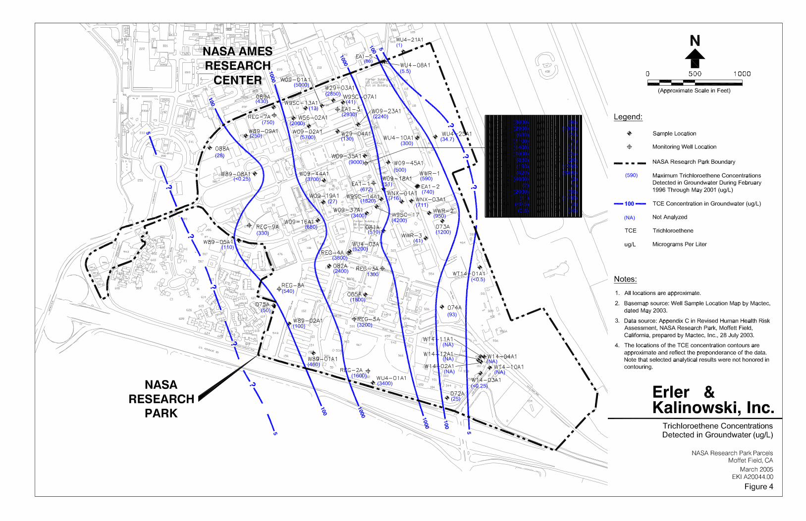


Decision Diagram forPre-Construction Planning of
Potential Modifications toRemediation Systems
NASA Research ParkMoffett Field, California
March 2005EKI A20044.00Figure 11
Erler &Kalinowski, Inc.
Are there other potentialdesign conflicts for wellor pipeline locations?
Initial Planning Meeting withrepresentatives of:
� Developer� NASA� Navy� MEW
Navy/MEW provide CADdrawings of existing
improvements
Are any existing wellslocated within 5 feet ofouter wall of planned
new building?
Are any pipelineslocated within 5 feet
of the outer edge of aplanned building footing
or foundation?
Developer notifies Navyor MEW and identifies
potential new well orpipeline location.
Navy/MEW coordinatesrequest for well sealing
and well/pipelinereplacement/relocation
with EPA, RWQCB, andSCVWD.
Well sealing and location ofreplacement well/pipeline
approved by EPA, RWQCB,and SCVWD
Developer and Navy/MEWcoordinate schedule for
protection, well sealing, andreplacement with construction
schedule
Navy/MEW contractors performdesign of any modifications to
remediation systems
Has EPA or RWQCBmodified proposed
locations for replacementwells/pipelines?
To Construction(Figure 15)
No
No
No
Yes
No
Yes
Yes
Yes
Abbreviations:MEW: MEW CompaniesEPA: U.S. Environmental Protection AgencySCVWD: Santa Clara Valley Water DistrictRWQCB: Regional Water Quality Control Board
Notes:1. Developer provides construction plans and schedule updates throughout project implementation; MEW/Navy are notified of and invited to scheduled construction meetings that relate to construction plans/schedules.
2. Notification is made to owner of specific system component in question.
1
2

Decision Diagram ForManagement of Dewatering Water
NASA Research ParkMoffett Field, California
March 2005EKI A20044.00Figure 12
Erler &Kalinowski, Inc.
Does WaterContain TPH> 50
ug/L?
Dewatering WaterProduced During
Construction
Collect and SampleWater and Analyze for
VOCsand TPH
Do ChemicalConcentrations ExceedRWQCB Shallow Water
Discharge Limits?
Use Water forDust Control or
Discharge to StormDrain
Is ConstructionSite within MEW or
Navy Allocation Area(Appendix A)?
Does WaterContain OnlyMEW VOCs?
Do ChemicalsExceed Allowable
POTW Limits?
Discharge to POTW inAccordance with
Wastewater DischargePermit
Coordinate with NASAand POTW to Obtain
Wastewater DischargePermit
Coordinate with MEW forDischarge to GWTS
Transfer Filtered Waterto Clean Tank near
MEW GWTS
MEW ManagesDischarge of Water to
GWTS
Coordinate with Navy forDischarge to WATS
Transfer Filtered Waterto Clean Tank Near
Navy WATS
Navy ManagesDischarge of Water to
WATS
Manage Residual FilterSolids in Accordance with
Protocol for ExcavatedSoil (Figure 16)
NavyMEWNo Yes
YesNo
Abbreviations:VOCs Volatile Organic CompoundsTPH Total Petroleum HydrocarbonsPOTW Publicly Owned Treatment WorksRWQCB Regional Water Quality
Control BoardMEW MEW CompaniesGWTS MEW Companies Groundwater
Treatment SystemWATS Navy's West Side Aquifer Treatment
System
Is POTW PermitApproved?
Yes
No
Yes No
Yes
Manage Residual FilterSolids in Accordance with
Protocol for ExcavatedSoil (Figure 17)
Manage Residual FilterSolids in Accordance with
Protocol for ExcavatedSoil (Figure 16 or 17)
1
2
Notes:1. Analyses to be conducted on water samples: VOCs by EPA Method 8260 TPH by EPA Method 8015m
2. MEW VOCs include: chloroform; 1,2-dichlorobenzene; 1,1-dichloroethane; 1,2-dichloroethane; 1,1-dichloroethene; cis-1,2-dichloroethene; trans-1,2-dichloroethene; Freon 113 (trichlorotrifluoromethane); tetrachloroethene; 1,1,1-trichloroethane; trichloroethene; and vinyl chloride.
No
Provide Clean Tank,Inspect, and Sample forAnalytical Parameters
Specified by MEW
Provide Clean Tank,Inspect, and Sample forAnalytical Parameters
Specified by Navy

Go toFigure 19 for
Stained/Discoloredor Odorous
Soil Management
ContinueConstruction
or otherSubsurfaceActivities
Go toFigure 19 for
Stained/Discoloredor Odorous
Soil Management
TPH extractable compounds by EPA Method 8015mTPH purgeable compounds by EPA Method 8015mHerbicides by EPA Method 8151Organochlorine Pesticides by EPA Method 8081PCBs by EPA Method 8082SVOCs by EPA Method 8270VOCs by EPA Method 8260, including Freon 113
1. Analyses to be conducted on samples
Title 22 Metals by EPA Method 6010
2. HazCat: Hazard Categorization
Yes
NASA Samples Contents of EachDrum or Container
Remove Contents and Place inAppropriate Container
No
No
Yes Yes
Are Drums or Containers Present?
Notify NASA
Do COPCConcentrations
Exceed the TargetCleanup Levels?
Yes
No
Developer Removes Drum orContainer; NASA Disposes at
Navy's Expense
Are Liquids PresentWithin the Drum(s) or
Container(s)?
NASA Transports and Disposes Drum orContainer at a Permitted
Off-Site Facility at Navy's Expense.NASA Signs Manifest as Generator
No
Do COPCConcentrations
Exceed the TargetCleanup Levels?
NASA Overpacks Drumor Container
NoIs Drum orContainer
in Good ShippingCondition?
Remove Drum or Container
Can theDrums or Containers
be Removed Safely Such That aSpill During the Removal
is Unlikely?
Yes
Yes
NASA Collects HazCat Sample (IfNeeded) and Analyzes the Sample forthe Analytical Parameters Specified
Do COPCConcentrations
Exceed the TargetCleanup Levels?
No
Yes
NASA Disposes of Drums or Containers atNavy's Expense. NASA Signs Manifests
as Generator.
No
Follow Santa Clara CountyRequirements for UST or Sump
Removal
Are Tanks or Sumps Present?
2
Yes
ContinueConstruction or
otherSubsurfaceActivities
1
Notes:
collected from drums or containers may include:
Abbreviations:
UST Underground Storage TankVOCs Volatile Organic CompoundsSVOCs Semi-volatile Organic CompoundsPCBs Polychlorinated Biphenyls
NASA Disposes of Contents atNavy's Expense. NASA Signs
Manifests as Generator.
NASA Collects RepresentativeSoil Sample Under the Drum
or Container
Collect Representative SoilSample Under the Drum or
Container
NASA Collects RepresentativeSoil Sample Under
the Drum or Container
Decision Diagram forManagement of Drums,
Containers, Tanks, or SumpsEncountered During Construction
NASA Research ParkMoffett Field, California
March 2005EKI A20044.00Figure 13
Erler &Kalinowski, Inc.
ContinueConstruction
or otherSubsurfaceActivities
Drums, Containers,Tanks, or Sumps
Encountered
COPC Chemical of Potential Concern
Sample Each Container of LikeMaterial and Analyze for the
Analytical Parameters Specified 1

Decision Diagram forAbandoned Pipe Management
During Construction
NASA Research ParkMoffett Field, California
March 2005EKI A20044.00Figure 14
Erler &Kalinowski, Inc.
Is Pipe Associated witha UST?
Abandoned PipeEncountered
Abbreviations:UST Underground Storage Tank
Follow Santa ClaraCounty Requirements
for UST Removal
Does Pipe ContainLiquid or Sludge?
Notify NASA
Remove Portion of PipeNecessary to Complete
Construction
Cap Ends of Pipe that Remainin Place
Dispose of Excavated PipeAppropriately
Is Soil Stained,Discolored, or AreOdors Present?
Go to Figure 19 forStained, Discolored, or
Odorous SoilManagement
No Further ActionRequired. Continue
Construction or OtherSubsurface Activities.
No
Yes
Yes
No
No
Yes
Test Liquid/Sludge forHazardous Constituents asRequired by the Disposal
Facility
Store and Dispose of Liquid orSludge Appropriately. IfHazardous Waste, NASA
Disposes at Navy's Expense.NASA Signs Manifest as
Generator.
Remove and Contain All Liquidor Sludge

Navy/MEWcontractors
implement finalmodifications to
existing remediationsystem features at
developer's expense
Decision Diagram forRemediation System Protection
During Construction
NASA Research ParkMoffett Field, California
March 2005EKI A20044.00Figure 15
Erler &Kalinowski, Inc.
Is shutdown of theremediation system>24 hours planned?
Is access to theremediation system
restricted?
Does an uncontrolledshutdown of remedial
system occur?
Developer implements work
Developer notifies Navy/MEW when final grade
changes have beencompleted
Navy/MEW seals wells to be closed
Navy/MEW installs, connects, andplumbs rerouted structures
Developer protects existingstructures during work, andmaintains access for O&M
Provide immediate verbalnotification to Navy/MEW
with follow-up writtenexplanation
Provide Navy/MEW written notice5 days in advance; Navy/MEW
coordinates with EPA for approvalof planned shutdown
Pre-ConstructionCoordination with
Navy/MEW complete(see Figure 11)
Navy/MEW contractorsshow locations of existingwells in field to developers
Developer installs well locationpipes or bollards and other
protective measures to protectwells/pipelines during
construction
Has an uncontrolledrelease of untreated
groundwater occurred?
No
Yes Yes
Yes
No
No
No
1
2
Take immediate action tocontrol release; coordinate with
MEW/Navy for follow-upresponse; Notify NASA
Yes
Abbreviations:MEW: MEW Companies
Notes:1. Developer provides construction plans and schedule updates throughout project implementation; MEW/Navy are notified of and invited to scheduled construction meetings that relate to construction plans/schedules.
2. Notification is made to owner of specific system component in question.

Decision Diagram forManagement of Excavated Soil in
MEW Allocation AreaNASA Research Park
Moffett Field, CaliforniaMarch 2005
EKI A20044.00Figure 16
Erler &Kalinowski, Inc.
IsConcentration >5 ppm for at
Least 10Seconds?
Are COPCs
Detected AboveTarget Concentration
Levels?
NASA or Developer CollectField Screening Sample
(1 sample/15 cy). Analyzewith OVA
Transfer Soil toPlastic-Lined Stockpile.Segregate and Manage
Saturated and UnsaturatedZone Soil Separately.
NASA or Developer CollectsStockpile Soil Samples (2 samples/
50 cy). Analyze for: VOCs, includingFreon 113 (EPA Method 8260) andTPHg/TPHd (EPA Method 8015m).
Is Soil VisiblyStained, Discolored,
Shiny, Oily, orOdorous?
Developer Uses Soilfor Cover or Backfill on
Project SIte
Do Saturated ZoneSoils Contain VOCs?
Is Soil fromUnsaturated Zone or
Does it ContainDetectable Levels of
TPH?
Does Soil ContainOnly VOCs
Associated with MEWPlume?
MEW Operates andMonitors Soil Treatment
and/or Disposal
Notify MEW and ProvideSoil Sampling Data for
Review
Transfer Soil to MEW SoilAeration Facility
No
Soil Excavated DuringConstruction
Go to Figure 19 forStained, Discolored,
and Odorous SoilManagement
Yes
Yes
NoYes
No
No
Notify MEW
Yes
Abbreviations:cy cubic yardOVA Organic Vapor Analyzerppm parts per millionVOCs Volatile Organic CompoundsMEW MEW CompaniesCOPC Chemical of Potential Concern
No
Notes:1. MEW VOCs include: chloroform; 1,2-dichlorobenzene; 1,1-dichloroethane; 1,2-dichloroethane; 1,1-dichloroethene; cis-1,2-dichloroethene; trans-1,2-dichloroethene; Freon 113 (trichlorotrifluoromethane); tetrachloroethene; 1,1,1-trichloroethane; trichloroethene; and vinyl chloride.
Notify Navy and ProvideSoil Sampling Data for
Review
Transfer Soil to Navy'sBioremediation/Aeration
Pad, Located East ofAirfield
NASA Operates andMonitors Soil Treatment
and/or Disposal atNavy's Expense
Yes
Yes
1
No
Developer Reviews AvailableDocumentation and Collects
Samples for Additional Testingas Needed
Do the Available Data
Indicate that COPCs Are Present
Above TargetConcentration
Levels?
No
Yes

Decision Diagram forManagement of Excavated Soil in
Navy Allocation Area
NASA Research ParkMoffett Field, California
March 2005EKI A20044.00Figure 17
Erler &Kalinowski, Inc.
IsConcentration >5 ppm for at
Least 10Seconds?
AreCOPCs
Detected AboveApplicable Target
ConcentrationLevels?
NASA or Developer CollectField Screening Sample
(1 sample/15 cy). Analyzewith OVA
Transfer Soil toPlastic-Lined Stockpile
NASA or Developer CollectsStockpile Soil Samples (2 samples/
50 cy). Analyze for: VOCs, includingFreon 113 (EPA Method 8260) andTPHg/TPHd (EPA Method 8015m).
Transfer Soil to Navy'sBioremediation/Aeration Pad, Located
East of Airfield
Is Soil VisiblyStained, Discolored,
Shiny, Oily, orOdorous?
NASA Operates andMonitors Soil Treatment
and/or Disposal atNavy's Expense
Notify Navy and ProvideSoil Sampling Data for
Review
No
Soil Excavated DuringConstruction
Go to Figure 19 forStained, Discolored,
and Odorous SoilManagement
Yes
Yes
No
No
Abbreviations:cy cubic yardOVA Organic Vapor Analyzerppm parts per millionVOCs Volatile Organic CompoundsMEW MEW CompaniesCOPC Chemical of Potential Concern
Yes
Developer Uses Soilfor Cover or Backfill on
Project Site
Developer Reviews AvailableDocumentation and Collects
Samples for Additional TestingAs Needed
Do theAvailable DataIndicate that
COPCs Are PresentAbove TargetConcentration
Levels?
No
Yes

Decision Diagram forManagement of
Lead-Impacted Soil
NASA Research ParkMoffett Field, California
March 2005EKI A20044.00Figure 18
Erler &Kalinowski, Inc.
Sample Excavated Soil inAccordance with Treatment/
Disposal Facility Requirements
NASA Transports to Off-SiteTreatment/Disposal Facility atNavy's Expense. NASA Signs
Manifest as Generator.
Has Lead-BasedPaint Survey Been
Performed?
Conduct Survey forLead-Based Paint
Was Lead Detected?
No Further ActionRequired
Has Initial Assessment of Lead inSoil Been Performed?
Was Total LeadDetected in Soil
Greater than 200 mg/kg?
Excavate Soil with ElevatedLead Concentrations as
Defined Through Soil Sampling
Collect Confirmation Samplesfrom Excavation Floor and
Sidewalls
Do ConfirmationSample Results Exceed
200 mg/kg? Yes
No
No
Yes
Was Soil DataCollected Adequate toIdentify Potential Areaswith Elevated Soil Lead
Concentrations?
Conduct Initial or AdditionalAssessment of Lead in Soil
No
Yes
No
Yes
No Further ActionRequired
No
Yes
No
Abbreviations:mg/kg milligrams per kilogram
ExcavationComplete
DevelopmentPlanned in Area with
Buildings thatPotentially Used Lead-
Based Paints
Yes
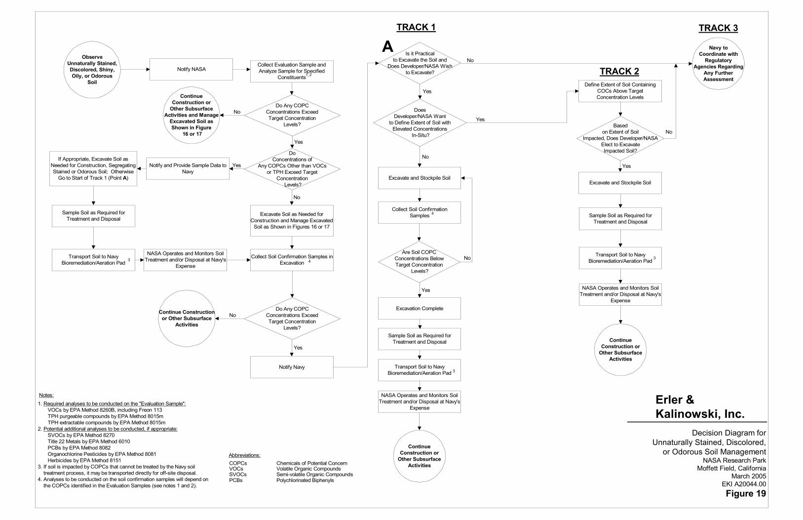
Sample Soil as Required forTreatment and Disposal
Notify and Provide Sample Data toNavy
Is it Practicalto Excavate the Soil and
Does Developer/NASA Wishto Excavate?
Notes:
Abbreviations:COPCs Chemicals of Potential ConcernVOCs Volatile Organic CompoundsSVOCs Semi-volatile Organic CompoundsPCBs Polychlorinated Biphenyls
Notify Navy
Decision Diagram forUnnaturally Stained, Discolored,
or Odorous Soil ManagementNASA Research Park
Moffett Field, CaliforniaMarch 2005
EKI A20044.00Figure 19
Erler &Kalinowski, Inc.
ObserveUnnaturally Stained,Discolored, Shiny,Oily, or Odorous
Soil
Notify NASA
ContinueConstruction or
Other SubsurfaceActivities and Manage
Excavated Soil asShown in Figure
16 or 17
DoConcentrations of
Any COPCs Other than VOCsor TPH Exceed Target
Concentration Levels?
Transport Soil to NavyBioremediation/Aeration Pad
NASA Operates and Monitors SoilTreatment and/or Disposal at Navy's
Expense
Do Any COPCConcentrations ExceedTarget Concentration
Levels?
Continue Constructionor Other Subsurface
Activities
DoesDeveloper/NASA Want
to Define Extent of Soil withElevated Concentrations
In-Situ?
Excavate and Stockpile Soil
Collect Soil ConfirmationSamples
Excavation Complete
Are Soil COPCConcentrations BelowTarget Concentration
Levels?
Sample Soil as Required forTreatment and Disposal
Transport Soil to NavyBioremediation/Aeration Pad
NASA Operates and Monitors SoilTreatment and/or Disposal at Navy's
Expense
ContinueConstruction or
Other SubsurfaceActivities
Define Extent of Soil ContainingCOCs Above TargetConcentration Levels
Basedon Extent of Soil
Impacted, Does Developer/NASAElect to ExcavateImpacted Soil?
Excavate and Stockpile Soil
Sample Soil as Required forTreatment and Disposal
Transport Soil to NavyBioremediation/Aeration Pad
NASA Operates and Monitors SoilTreatment and/or Disposal at Navy's
Expense
ContinueConstruction or
Other SubsurfaceActivities
Navy toCoordinate with
RegulatoryAgencies Regarding
Any FurtherAssessment
No
Yes
No
Yes
No
Yes
Yes
No
Yes
No
Yes
No
Yes
1,2
3
3
3
4
1. Required analyses to be conducted on the "Evaluation Sample": VOCs by EPA Method 8260B, including Freon 113 TPH purgeable compounds by EPA Method 8015m TPH extractable compounds by EPA Method 8015m2. Potential additional analyses to be conducted, if appropriate: SVOCs by EPA Method 8270 Title 22 Metals by EPA Method 6010 PCBs by EPA Method 8082 Organochlorine Pesticides by EPA Method 8081 Herbicides by EPA Method 81513. If soil is impacted by COPCs that cannot be treated by the Navy soil treatment process, it may be transported directly for off-site disposal.4. Analyses to be conducted on the soil confirmation samples will depend on the COPCs identified in the Evaluation Samples (see notes 1 and 2).
TRACK 1 TRACK 3
TRACK 2
If Appropriate, Excavate Soil asNeeded for Construction, SegregatingStained or Odorous Soil; Otherwise
Go to Start of Track 1 (Point A)
Collect Evaluation Sample andAnalyze Sample for Specified
Constituents
Do Any COPCConcentrations ExceedTarget Concentration
Levels?
Excavate Soil as Needed forConstruction and Manage Excavated
Soil as Shown in Figures 16 or 17
NoCollect Soil Confirmation Samples inExcavation 4
A

EKI A20044.00 FINAL – 1 March 2005
APPENDIX A
MEW Companies/Navy/NASA Allocation Area Map


EKI A20044.00 FINAL – 1 March 2005
APPENDIX B
Mitigated Alternative 5 Land Use Plan from Final Programmatic Environmental Impact Statement
Figure 2.6 from Design, Community, and Environment, NASA Ames Development Plan, Final Programmatic Environmental Impact Statement, NASA Ames Research Center, July 2002


EKI A20044.00 FINAL – 1 March 2005
APPENDIX C
Selected Plates from the Revised Human Health Risk Assessment
Mactec, Inc., Revised Human Health Risk Assessment, NASA Research Park, Moffett Field, California, 28 July 2003 Includes:
• Plate 8: Indoor Worker RME Risk;
• Plate 10: Indoor Worker RME HI;
• Plate 16: Child Resident (10 yr) RME Risk;
• Plate 18: Child Resident (10 yr) RME HI;
• Plate 20: Resident (30 yr) RME Risk;
• Plate 22: Resident, Child (6 yr) HI,


EKI A20044.00 FINAL – 1 March 2005
APPENDIX D
Agreement for Coordination of Construction and MEW Remedial System Modification Work NASA Research Park, Moffett Federal Airfield

Page 1 of 13 NASA\38753\507131.1
AGREEMENT FOR COORDINATION OF CONSTRUCTION AND MEW REMEDIAL SYSTEM MODIFICATION WORK AT
NASA RESEARCH PARK, AMES RESEARCH CENTER, MOFFETT FIELD, CALIFORNIA
The National Aeronautics and Space Administration (“NASA”) enters into this
Agreement for Coordination of Construction and MEW Remedial System Modification Work at NASA Research Park, Ames Research Center, Moffett Field, California (“Agreement”) with Fairchild Semiconductor Corporation, a Delaware corporation, and Raytheon Company, a Delaware corporation (collectively, the “MEW Companies”), and CM SPE, LLC, a Pennsylvania limited liability company (“Project Developer”). NASA enters into this Agreement pursuant to the authority of the National Aeronautics and Space Act of 1958, as amended, 42 U.S.C. §§ 2451 et seq.
RECITALS
A. On June 9, 1989, the United States Environmental Protection Agency (“EPA”) issued a Record of Decision (the “MEW ROD”) for the Middlefield-Ellis-Whisman area of Mountain View, California. The MEW ROD was modified in September 1990 and April 1996 by EPA’s Explanations of Significant Differences. The MEW ROD requires the implementation of an EPA-approved regional groundwater remediation program (“RGRP”).
B. On November 29, 1990, pursuant to Section 106(a) of the Comprehensive Environmental Response, Compensation, and Liability Act of 1980, as amended by the Superfund Amendments and Reauthorization Act of 1986 (as so amended, “CERCLA”) (42 U.S.C. § 9606(a)), the EPA issued an Administrative Order for Remedial Design and Remedial Action for the MEW Site to Fairchild Semiconductor Corporation, Schlumberger Technology Corporation, National Semiconductor Corporation, NEC Electronics, Inc., Siltec Corporation, Sobrato Development Companies, General Instrument Corporation, Tracor X-Ray, Inc., and Union Carbide Chemicals and Plastics Company Inc. (the “106 Order”).
C. On May 9, 1991, pursuant to CERCLA, the EPA entered into a Consent Decree with Intel Corporation and Raytheon Company to compel them to perform remedial actions at the MEW Site.
D. As part of the RGRP, the MEW Companies have installed, operate, monitor and maintain a groundwater monitoring and remedial system (“Remedial System”) on Moffett Field (“Moffett”) under the direction of EPA. The Remedial System’s components include, but are not limited to, groundwater monitoring wells, groundwater extraction wells, single and double-contained pipelines, air relief structures, electrical power and instrumentation conduits, fiber-optic instrument systems, electrical field control panels, leak detection systems, radio frequency communication links, settlement pin monuments and a groundwater treatment system (“GWTS”). The MEW Companies are required by EPA to operate the Remedial System GWTS and related

Page 2 of 13 NASA\38753\507131.1
extraction wells and components continuously except during maintenance. Approval for any shutdown of more than 24 hours duration must be obtained from the EPA Remedial Project Manager (“RPM”) in advance.
E. NASA has entered into an agreement with the Project Developer to undertake redevelopment activities at Moffett in connection with the Project Developer’s lease of certain improvements at Moffett. These activities include, but are not limited to, demolition, grading, trenching and other excavation work, and construction connected with the development of office, educational, and research and development facilities (collectively, “Project Development”).
F. NASA, the MEW Companies and the Project Developer enter into this Agreement to minimize any impact of Project Development on the operation, monitoring, maintenance and modification of the Remedial System and to allow MEW Companies and the EPA access to the Remedial System during and after Project Development; and to delineate the roles and responsibilities for managing contaminated soil and groundwater that is excavated during the Project Development. NASA, the MEW Companies and the Project Developer recognize that, to coordinate Project Development and the continued operation of the Remedial System effectively, it will be necessary for NASA, the Project Developer and the MEW Companies to be in regular, frequent communication.
G. The Parties to this Agreement all agree that all actions to be taken hereunder shall be in compliance with all applicable laws and, to the extent required by law, will receive the approval of all state and federal agencies having jurisdiction over such actions.
NOW, THEREFORE, NASA, Project Developer and the MEW Companies agree as follows:
AGREEMENT
1. Geographic Scope of Agreement
This Agreement applies only within those geographical parts of Moffett that are or will be physically affected by the construction work performed by the Project Developer in connection with the Project Development and located within the areas designated as AR-1 and AR-3 on the attached Figure 1, together with other areas that may be affected by extensions of portions of the Remedial System that extend from AR-1 and/or AR-3.
2. Scheduling of Work
The Project Developer shall meet with the MEW Companies as early as possible during Project Development planning to coordinate Project Development with the operation, monitoring, maintenance and modification of the Remedial System. Detailed drawings showing the locations of the Remedial System components shall be provided by the MEW Companies to the Project Developer in CAD form so they can be integrated into the Project Developer’s plans.

Page 3 of 13 NASA\38753\507131.1
3. Remedial System Protection and Modification; Exacerbation of Contamination
During Project Development, (i) the Project Developer shall protect the integrity of all components of the Remedial System and shall take all reasonable measures to minimize Remedial System downtime, in each case to the extent the Remedial System may be affected as a result of the Project Development, and (ii) the MEW Companies shall operate the Remedial System in a manner that, to the extent reasonably possible and subject to the express requirements of this Agreement, minimizes interference with the ongoing Project Development. After completion of Project Development, the MEW Companies both (a) shall protect the integrity of all components of facilities resulting from the Project Development and (b) shall take all reasonable measures to minimize interference with the Project Developer’s use of its facilities, in each case to the extent they may be affected as a result of the operation of the Remedial System, provided that the MEW Companies shall not be required to relocate components of the Remedial System as they exist on the date of this Agreement. The Project Developer shall pay any costs of relocation, replacement, alteration, protection, modification, or repair of the Remedial System caused by Project Development, to the extent any such relocation, replacement, alteration, protection, modification or repair is required by applicable laws and/or is required for the Remedial System to operate in substantially the same manner it operated prior to any such relocation, replacement, alteration, protection, modification or repair caused or necessitated by the Project Development. In addition, if the Project Developer damages any Remedial System component in a manner that causes a release of untreated groundwater or soil or if the Project Developer exacerbates existing soil or groundwater contamination, the Project Developer shall pay all costs of investigation, remediation, EPA oversight, and any penalties associated with such release or exacerbation. The design and construction of any modification to the Remedial System shall be performed by the MEW Companies; all modification costs, including EPA oversight costs, shall be paid by the Project Developer, subject to Section 18.
4. Well Protection
The Project Developer shall repair any damage to Remedial System wells caused by Project Development. Prior to the initial Project Development demolition or construction field work, the MEW Companies shall field locate all Remedial System wells. Prior to the start of Project Development field work, the Project Developer shall install brightly painted steel pipes over each Remedial System monitoring and extraction well designated by the MEW Companies. The painted pipe shall extend above ground not less than four feet, so as to be highly visible, and shall be buried sufficiently below the ground surface to protect the wellhead. Alternative equivalent well protection measures may be used by the Project Developer provided the MEW Companies approve any alternative protective measure in writing prior to its use.
Additionally, all Project Development work within two (2) feet of Remedial System wells shall be performed manually with hand tools. Fine grading work

Page 4 of 13 NASA\38753\507131.1
performed in areas more than two feet from the Remedial System wells but within close proximity shall be performed by light grading equipment.
5. Well Sealing and Well Replacement
If the Project Developer determines that a Remedial System well conflicts with the planned Project Development and must be removed, the Project Developer shall pay all costs of well sealing and replacement and all related MEW Companies’ costs, including but not limited to the cost of installing replacement conduit, piping, boxes, controls and all other components needed to return a well to service, developing the well, conducting a baseline first round of groundwater sampling, and preparing all required plans, surveys and reports. The Project Developer shall be responsible for sealing all wells located within 15 feet of the outer wall of a new building. No well shall be sealed or relocated without the prior written approval of the EPA RPM. Well sealing and installation shall comply with Santa Clara Valley Water District (“SCVWD”) guidance and take place under SCVWD permit. Coordination with EPA and well sealing and replacement shall be performed by the MEW Companies, at the Project Developer’s sole cost, subject to Section 18.
6. Remedial System Pipeline Protection and Replacement
Prior to initial Project Development field work, the Project Developer shall provide and place steel plate or equivalent protective measures over the existing MEW Companies’ pipelines and power and control conduits. If the Project Developer determines that a pipeline conflicts with the planned Project Development and must be removed and relocated, the Project Developer shall pay all costs related to pipeline removal and replacement, including but not limited to design, permitting, review, inspection, construction and independent quality assurance inspection costs. The Project Developer shall be responsible for removing and relocating all pipelines located within five feet of the outer edge of the footing or foundation of a new building. No pipeline shall be relocated without the prior approval of the EPA RPM. Replacement pipeline installation procedures shall also be approved by the EPA RPM. Coordination to obtain EPA approval, and pipeline removal and replacement work, shall be performed by the MEW Companies at the Project Developer’s cost, subject to Section 18.
7. Notification of Shutdown of Groundwater Extraction Wells or GWTS
If, during Project Development, the Project Developer believes it to be necessary that either a Remedial System extraction well or the GWTS be shut down, the Project Developer shall make written request of same to the MEW Companies no later than five (5) working days in advance of the proposed shutdown. If such shutdown does not require EPA approval, the MEW Companies shall, within five (5) working days of receipt of the Project Developer’s written request, notify Project Developer in writing either that (a) the MEW Companies consent to such request, including information on the anticipated timing of the shutdown or (b) the MEW Companies do not consent to such request and the reason(s) for such refusal. If such shutdown does require EPA approval, the MEW Companies shall, promptly upon receipt of the Project Developer’s written

Page 5 of 13 NASA\38753\507131.1
request, make appropriate application to EPA for its consent and shall notify the Project Developer of EPA’s response within one (1) working day of its receipt of EPA’s response or, failing a response from EPA within fifteen (15) working days, shall notify the Project Developer of EPA’s lack of response and any additional steps the MEW Companies have taken to elicit a response. In the event of an inadvertent shutdown of any component of the Remedial System, the Project Developer shall give immediate verbal notice to the MEW Companies, and the MEW Companies shall be responsible for any required notice to EPA pursuant to the 106 Order. Additionally, the Project Developer shall provide to the MEW Companies a written explanation of the reason for and the duration of any inadvertent shutdown within 48 hours of the shutdown.
8. Access to Wells and the GWTS
Project Development shall be performed in such a way that all Remedial System wells, pull boxes and the GWTS and associated components remain accessible to the EPA and the MEW Companies and their equipment for sampling, operation, maintenance, removal and replacement of pumps, and well sealing to the maximum extent practicable during and after Project Development. If it becomes necessary to restrict access to a well or other Remedial System component during Project Development, the Project Developer shall provide written notice to the MEW Companies five working days in advance of creating the restriction, with an explanation of the reason for and the expected duration of the proposed restricted access. Prior to the initial Project Development field work, the MEW Companies shall provide the Project Developer with the schedule for well sampling.
9. Modifications to Well Vaults and Wellheads
Following completion of final grade by the Project Developer, the MEW Companies shall modify the MEW wells, well vaults, and pull boxes as needed based on the final grade established by the Project Developer. All costs associated with these modifications shall be paid by the Project Developer, subject to Section 18.
10. Communications
The Project Developer, all of its contractors, the MEW Companies, all of their contractors, and NASA shall each designate in writing a primary and alternate contact person, including all applicable mailing addresses, telephone numbers, email addresses and facsimile numbers. The MEW Companies shall have sole authority and responsibility for all communications with EPA regarding the Remedial System, including its operating status, any Project Development-related shutdowns and any modifications. The Project Developer shall provide the MEW Companies with all demolition, grading and construction work schedules, a full set of civil, landscaping, foundation and utility plans and specifications, and updates to these plans and specifications and schedules promptly as they occur. The MEW Companies and their contractor shall be notified of and invited to weekly construction meetings that pertain to these plans and schedules.

Page 6 of 13 NASA\38753\507131.1
11. Monitoring and Sampling of Excavated Soil
The Project Developer or NASA shall monitor all excavated soil to determine if the soils contain volatile organic compounds (“VOCs”) or petroleum constituents. Vadose zone soils shall be stockpiled and managed separately from saturated zone soils. The Project Developer shall remove and segregate concrete, asphalt, wood, piping and other demolition debris from soil and shall manage and dispose of demolition debris in accordance with all applicable regulations. The Project Developer shall pay all costs related to demolition debris disposal.
NASA, at the Project Developer’s expense and in compliance with applicable laws, shall monitor and sample soils generated from trenching and other excavation work throughout trenching and excavation activities. The soil being removed shall be visually observed for evidence of discoloration or staining. Soil exhibiting these characteristics shall be analyzed using an organic vapor analyzer (“OVA”) or equivalent device before stockpiling. Excavated soil shall be field-screened using an OVA (or equivalent) to determine if the excavated soils are clean or may be chemically affected. Field screening shall be performed in a manner acceptable to EPA, which the Project Developer, NASA and the MEW Companies currently expect will be performed with an OVA (or equivalent) at a rate of one soil sample for every 15 cubic yards of excavated soil. Excavated soils that show a continuous reading of five parts per million (“ppm”) or greater for at least ten seconds using the OVA (or equivalent) shall be considered as possibly containing chemicals, and shall be segregated. NASA shall transfer soil exhibiting these characteristics to a plastic-lined stockpile area in or near the area of trenching or excavation. Soil samples shall be collected from random locations within the stockpile at a rate of two samples for every 50 cubic yards of stockpiled soil. Each of the two samples shall consist of at least five composite samples representative of the stockpiled soil. The samples shall be submitted to a state-certified laboratory and analyzed using EPA Method 8260 (or its superceding EPA Method), including cis-1, 2-dichloroethene and Freon 113 and EPA Method 8015 (or its superceding EPA Method) for high and low boiling point total petroleum hydrocarbons (“TPH”). After the soil has been verified to conform to the soil cleanup standards specified in the MEW ROD, the soils may be used for on-site cover or backfill. Clean soil that is tested using the field head space method with an OVA (or equivalent) that does not have a reading greater than five ppm for at least ten seconds also may be used for on-site cover or backfill. Soil that does not qualify as clean soil shall be managed in accordance with Sections 13.2 through 13.6 of this Agreement.
11.1 Excavated Soil Classification and Monitoring Procedure
The Project Developer or NASA shall monitor excavated soil with an OVA (or equivalent) to determine if the soils are clean or may contain chemicals, as defined below:
Clean Soil: Soil that does not have a reading greater than five ppm continuously for ten seconds using the field head space method with an OVA (or equivalent) specified below will be considered clean soil.

Page 7 of 13 NASA\38753\507131.1
Soil Containing Chemicals: Soil that does not meet the definition of clean soil will be considered soil containing chemicals.
11.2 Field Head Space Methods:
(a) A soil sample shall be taken from excavated soil in the backhoe bucket at a point out of the excavation.
(b) The soil to be tested shall be placed into an unused re-sealable plastic bag or clean mason jar container with a minimum volume of one quart or one liter, until the container is half full.
(c) The container shall be sealed and left to sit under direct sunlight for approximately five minutes.
(d) The container shall be opened just enough to allow the probe of the OVA (or equivalent) to be inserted into the container’s headspace.
(e) Any sample having a reading of five ppm or greater continuously for at least ten seconds shall be considered soil containing chemicals.
12. Notification of Saturated Soil Containing VOC
If VOCs are determined to exist in saturated zone soils, the Project Developer shall immediately notify the MEW Companies’ representative.
13. Management and Disposition of Soils
13.1 Clean Soil
NASA shall be responsible for the determination as to whether soil qualifies as clean soil either because it has been classified as clean soil in accordance with Section 11.1 of this Agreement or has been treated to the soil cleanup standards specified in the MEW ROD. Clean soil that does not require treatment may be reused for cover or backfill or shall be transported to the open field north of Electrical Substation West (N225A) on Moffett, shown as Area A on the attached Figure 2, or to other areas on Moffett designated by NASA, and spread by the Project Developer at the Project Developer’s cost. NASA and the Project Developer agree that the MEW Companies shall not be responsible for (a) any determination made by NASA or the Project Developer that any soil qualifies as clean soil or that any soil may be used for any particular purpose at any particular location on Moffett, or (b) any other actions or omissions by NASA or the Project Developer with respect to their respective handling of soils pursuant to this Agreement.
13.2 Vadose Zone Soils and Saturated Soils Containing TPH
Vadose zone and saturated soils containing TPH from AR-1 (whether or not they also contain VOCs) shall be transported by the Project Developer to the

Page 8 of 13 NASA\38753\507131.1
bioremediation pad on the east side of Moffett, as shown on Figure 3, or to other areas on Moffett designated by NASA, and shall be managed by NASA in accordance with the procedures specified in the document entitled “Coordination of Construction and Navy Remedial System Modification Work.”
Vadose zone and saturated soils containing TPH from AR-3 (whether or not they also contain VOCs) shall be transported by the Project Developer to the bioremediation pad at the northwest corner of Moffett, shown as Area C on Figure 2, or to other areas on Moffett designated by NASA, and shall be managed by NASA.
13.3 Saturated Zone Soils Containing Only VOCs
The Project Developer shall notify the MEW Companies promptly if any saturated zone soil in AR-1 or AR-3 is determined by analytical testing to contain only those VOCs associated with the MEW plume at concentrations exceeding MEW ROD soil cleanup standards. The MEW Companies shall manage and dispose of these soils at their cost. The Project Developer or NASA shall promptly make available to the MEW Companies copies of analytical soil data. Following review of the data, any soils that are found to be the responsibility of the MEW Companies shall be delivered by the Project Developer to a soil aeration facility on Moffett at the location shown as Area B on Figure 2 (the “MEW Soil Aeration Facility”) and treated and/or disposed of by the MEW Companies. Treatment or offsite disposal of the soil shall be at the discretion and timing of the MEW Companies, in accordance with CERCLA Section 121(d). If treated, the soils shall be treated to the soil cleanup standards specified in the MEW ROD. The Project Developer shall pay all costs of excavating and delivering the soil to the MEW Soil Aeration Facility. The MEW Companies shall pay all costs of treating the soil and spreading the treated soil on-site or disposing of it offsite. If the MEW Companies elect to dispose of soil offsite, the MEW Companies shall select the offsite disposal site in accordance with CERCLA Section 121(d), subject to NASA’s approval, which shall not be withheld unreasonably, and NASA shall be designated the generator and sign all necessary waste manifests.
13.4 Polyethylene Liners
The Project Developer shall provide plastic liners and covers for the soil stockpiles located in the areas of trenching and excavation. The MEW Companies shall provide liners and covers for the soil at the MEW Soil Aeration Facility. The location of the soil stockpiles in the areas of trenching and excavation shall be designated by NASA.
13.5 MEW Soil Aeration Facility Sampling and Testing Procedures
Following aeration of soils treated by the MEW Companies pursuant to Section 13.3, the MEW Companies shall collect two discrete soil samples for every 50 cubic yards of treated soil. Each of the two samples shall consist of at least five composite samples representative of the treated soil. The samples shall be analyzed using EPA Method 8260 (or its superceding EPA Method), including cis-1,2-dichloroethene and Freon.

Page 9 of 13 NASA\38753\507131.1
13.6 On-Site Reuse
After soil aerated by the MEW Companies has been determined to meet soil cleanup standards, the MEW Companies shall move the clean soil onto the open field adjacent to the MEW Soil Aeration Facility and spread it in a manner that effectively separates the clean soil from any soil remaining at or brought to the MEW Soil Aeration Facility for treatment.
13.7 Soil Management
All soil management plans (including, without limitation, those for screening, testing, treating and disposing of soils) shall be performed in accordance with EPA-approved plans to the extent required by the 106 Order.
14. Management and Discharge of Groundwater Generated During Excavation and Dewatering Activities
The Project Developer may be required to dewater pipeline trenches and other excavations and convey water away from excavations. Groundwater in the area of Project Development may contain VOCs or TPH. The Project Developer shall manage, contain and discharge all water removed from excavation areas. The Project Developer shall transport the water to above ground tanks, test the water by EPA Method 8260 and EPA Method 8015 (or their superceding EPA Methods) and discharge the water as follows:
14.1 Ground Water Containing TPH
If the groundwater from AR-1 contains TPH above 50 parts per billion (“ppb”) (or such lower standard as may in the future be established by EPA), as determined by EPA Method 8015 (or its superceding EPA Method), it shall not be discharged to the Remedial System GWTS. The Project Developer shall obtain all necessary approvals for discharge of such groundwater at alternate sites. (Depending on the chemical concentrations, the Project Developer may be able to obtain permission from the City of Sunnyvale Waste Water Treatment Plant or the City of Palo Alto Waste Water Treatment Plant to discharge the water to the NASA sanitary sewer systems.) The water shall be filtered before any discharge to the sewer system and the solids stored and subsequently managed by the Navy in accordance with the document entitled “Coordination of Construction and Navy Remedial System Modification Work.”
If the groundwater from AR-1 contains TPH above 50 ppb, and cannot be discharged to the sanitary sewer, the Project Developer shall deliver it to the Navy’s Westside Aquifer Treatment System on Moffett for treatment by the Navy.
If the groundwater from AR-3 contains TPH above 50 ppb, as determined by EPA Method 8015 (or its superceding EPA Method), it shall not be discharged to the Remedial System GWTS. The Project Developer shall obtain all necessary approvals for discharge of such groundwater at alternate sites. (Depending on the chemical concentrations, the Project Developer may be able to obtain permission from the City of

Page 10 of 13 NASA\38753\507131.1
Sunnyvale Waste Water Treatment Plant or the City of Palo Alto Waste Water Treatment Plant to discharge the water to the NASA sanitary sewer systems.) The water shall be filtered before any discharge to the sewer system and the solids stored and subsequently managed by the Navy in accordance with the document entitled “Coordination of Construction and Navy Remedial System Modification Work.”
If the groundwater from AR-3 contains TPH above 50 ppb, and cannot be discharged to the sanitary sewer, the Project Developer shall deliver it to NASA’s RGRP Treatment System on Moffett for treatment by NASA.
14.2 Groundwater Containing VOCs
If the groundwater from AR-1 or AR-3 contains TPH below 50 ppb (or such lower standard as may in the future be established by EPA) and contains VOCs that are identified as those associated with the MEW plume, the groundwater can be discharged, if acceptable to EPA (to the extent EPA approval is required by the 106 Order), to the Remedial System GWTS. If EPA approves (if such approval is so required), then the Project Developer shall deliver the groundwater to clean Baker or similar tanks adjacent to the Remedial System GWTS at the location shown as the MEW Baker Tank Staging Area on Figure 4. The Project Developer shall inspect and sample the storage tanks before using them to insure that they are clean. Sample results shall be provided to the MEW Companies, and the MEW Companies shall have an opportunity to inspect the tanks before their use. Treatment and discharge of groundwater through the Remedial System GWTS shall be performed by the MEW Companies. All groundwater shall be filtered before it is pumped into the clean storage tanks to minimize sediment buildup in the storage tanks. All solids removed from the groundwater and any filters shall be stored and subsequently characterized, managed and disposed of in the same manner as contaminated soils as specified in Sections 11 through 13 of this Agreement. NASA shall be designated the generator and shall sign all necessary waste manifests for the solids and filter wastes. The Project Developer shall pay all costs associated with extraction, delivery and storage of groundwater prior to treatment at the GWTS. The MEW Companies shall pay all costs of pumping the groundwater from the storage tanks and treating it through the Remedial System GWTS. The MEW Companies shall treat the stored water within a reasonable timeframe.
15. Contractor Compliance With This Agreement
NASA, the MEW Companies, and the Project Developer each shall provide a copy of this Agreement to their respective contractors and subcontractors and shall ensure that compliance with this Agreement is made a material part of their respective agreements with their contractors and subcontractors.
16. NASA Appropriations
NASA agrees to use its best efforts in the performance of this Agreement. However, all NASA activities under or pursuant to this Agreement are subject to the availability of appropriated funds. No provision of this Agreement shall be interpreted

Page 11 of 13 NASA\38753\507131.1
as, or constitute, a commitment or requirement that NASA or any other Federal Agency obligate or pay funds in contravention of the Anti-Deficiency Act, 31 U.S.C. 1341. Notwithstanding the foregoing, NASA agrees that, during the period in which this Agreement remains operative, NASA will be diligent in seeking appropriation of funds for the purpose of performing NASA’s obligations set forth in this Agreement.
17. Notices
All written notices required by this Agreement shall be deemed effective (1) when delivered, if personally delivered to the person being served or (2) three business days after deposit in the mail if mailed by United States mail, postage paid certified, return receipt requested:
If To: “Project Developer”:
CM SPE, LLC 5000 Forbes Avenue Pittsburgh, PA 15213 Attn: Duane A. Adams Facsimile: (412) 268-2990
If To: “MEW Companies”
Fairchild Semiconductor Corporation Clifford E. Kirchof Remediation Manager Schlumberger Limited 225 Sugar Land Drive Sugar Land, TX 77478 Facsimile: (281) 285-8597
Jeffrey B. Axelrod, Esq. Senior Counsel Raytheon Corporation 141 Spring Street Lexington, MA 02421 Facsimile: (781) 860-2788
If To: “NASA”
Mr. Don Chuck NASA Ames Research Center MS 218-1 Moffett Field, CA 94035 Facsimile: (650) 604-0680

Page 12 of 13 NASA\38753\507131.1
18. Review/Audit of MEW Costs
With respect to any and all work to be performed by the MEW Companies hereunder at Project Developer’s cost, including, without limitation, work performed pursuant to Sections 3, 5, 6 and 9 hereof:
18.1 All such work shall be conducted only to the extent required by applicable laws and/or to enable the Remedial System to operate in substantially the manner it operated prior to any damage, modification or alteration caused or required by the Project Development, and all costs related to such work shall be commercially reasonable and subject to Project Developer’s prior approval in accordance with this Section 18, which approval shall not be unreasonably withheld or delayed;
18.2 Prior to commencing such work and incurring such costs, the MEW Companies shall provide to Project Developer a detailed description of such work and cost estimates and such back-up documentation as Project Developer may reasonably request, and Project Developer shall be given an opportunity to recommend revisions or modifications to such scope of work and cost estimates. Project Developer shall either approve or disapprove (with reasonable detail as to grounds for disapproval) such work scope and cost estimate within thirty (30) days after receipt of same, unless sooner approval or disapproval is required for emergency repairs, in which case Project Developer shall respond as promptly as reasonable practicable;
18.3 After completing such work and incurring such costs, the MEW Companies shall provide to Project Developer paid invoices and such other evidence of payment of such costs previously approved by Project Developer as Project Developer may reasonably request; and
18.4 Project Developer shall have a period of thirty (30) days after submission of such proof of payment to review such costs and the work performed and, at Project Developer’s sole option and expense, to complete an audit of the MEW Companies’ records with respect to such costs and work performed. If, as a result of such review and/or audit, Project Developer determines that any such work and/or costs are outside the scope of Project Developer’s responsibility hereunder and/or were not approved by Project Developer as required hereunder, then Project Developer shall so notify the MEW Companies and the parties shall attempt to resolve such dispute extrajudicially. If the Project Developer and MEW Companies are unable to resolve such dispute extrajudicially, then either party may pursue any available remedy pursuant to applicable law or, by mutual agreement, may submit the dispute to such alternative dispute resolution procedure as may be mutually acceptable.
19. Effective Date
This Agreement shall take effect on January 8, 2003.

Page 13 of 13 NASA\38753\507131.1
IN WITNESS THEREOF, the following parties have entered into this Agreement.
NATIONAL AERONAUTICS AND SPACE ADMINISTRATION
By: ___________________________ Dated: G. Scott Hubbard Title: Director, Ames Research Center
CM SPE, LLC
By: ___________________________ Dated: ___________________ Duane Adams Title: President and CEO
RAYTHEON COMPANY
By: Dated: Title:
FAIRCHILD SEMICONDUCTOR CORPORATION
By: Dated: Title:

305723.1 1
Exhibit O
REQUIREMENTS AND PROCEDURES FOR COORDINATION OF
CONSTRUCTION AND NAVY REMEDIAL SYSTEM MODIFICATION
WORK AT NASA RESEARCH PARK, AMES RESEARCH CENTER,
MOFFETT FIELD, CALIFORNIA
The National Aeronautics and Space Administration (“NASA”) will enter into a
certain Agreement for Coordination of Construction and Navy Remedial System
Modification Work at the proposed NASA Research Park (“NRP”), Ames Research
Center, Moffett Field, California (“Agreement”) with the United States Navy. The
following recitals, requirements and procedures are taken from the proposed Agreement
and will be followed by NASA, the Navy and CM SPE, LLC (“CM SPE”) in regard to
the activities under Article 26 of the Lease.
RECITALS
A. On June 9, 1989, the United States Environmental Protection Agency
(“EPA”) issued a Record of Decision (the “MEW ROD”) for the Middlefield-Ellis-
Whisman area of Mountain View, California. The MEW ROD was modified in
September 1990 and April 1996 by EPA’s Explanations of Significant Differences. The
MEW ROD requires the implementation of an EPA-approved regional groundwater
remediation program (“RGRP”).
B. In September, 1990, a Federal Facility Agreement (“FFA”) under
CERCLA Section 120 was signed by the EPA, the Navy, and the State of California,
represented by the California Department of Health Services (“DHS”), and the California
Regional Water Quality Control Board (“RWQCB”). The FFA states the Navy’s
responsibilities for the investigation and remediation of contaminated soil and
groundwater within the proposed NRP area.
C. On December 22, 1992, the Navy and NASA signed a Memorandum of
Understanding (“MOU”) that stated the Navy would continue to be responsible for the
investigation and remediation of its environmental contamination after the transfer of the

305723.1 2
former Naval Air Station Moffett Field to NASA. In addition to the groundwater
contamination, the MOU includes Navy responsibility for petroleum contamination in the
soil and groundwater, and for lead in the soil caused by lead based paint on the buildings.
This MOU was further clarified by the Navy in a letter signed on October 4, 1993, which
stated that “The Navy’s obligations under the MOU shall include taking possession of,
and properly managing any contaminated soil or groundwater that has been left in place
in accordance with a CERCLA, RCRA, or other cleanup remedy but subsequently upon
its excavation, disturbance, or discharge by NASA during development for reuse of
Moffett Field becomes hazardous waste, or requires treatment prior to discharge.”
D. On December 17, 1993, EPA signed the Moffett Field FFA amendment,
which had already been signed by the Navy, the California Department of Toxic
Substance Control (“DTSC”) and the RWQCB. In this FFA amendment, the Navy
adopted the MEW ROD for the remediation of soil and groundwater contaminated with
chlorinated solvents within the proposed NRP area.
E. By 1998, the Navy, NASA, and the MEW Companies had agreed in
principle to an allocation and settlement of each party’s responsibilities for the RGRP.
NASA and the MEW Companies signed this Allocation and Settlement Agreement on
March 16, 1998.
F. As part of the RGRP, the MEW Companies have installed, operate,
monitor and maintain a groundwater monitoring and remedial system on Moffett Field
(“Moffett”) under the direction of EPA. These components include, but are not limited
to, groundwater monitoring wells, groundwater extraction wells, single and double-
contained pipelines, air relief structures, electrical power and instrumentation conduits,
fiber-optic instrument systems, electrical field control panels, leak detection systems,
radio frequency communication links, settlement pin monuments and a groundwater
treatment system (“GWTS”). The MEW Companies are required by EPA to operate the
GWTS and related extraction wells and components continuously except during
maintenance. Approval for any shutdown of more than 24 hours duration must be
obtained from the EPA Remedial Project Manager (“RPM”) in advance.
G. Pursuant to its FFA, the Navy has installed, operates, monitors and
maintains a groundwater monitoring and remedial system, the Westside Aquifer

305723.1 3
Treatment System (“WATS”) on Moffett under the direction of EPA and the RWQCB.
The WATS’ components include, but are not limited to, groundwater monitoring wells,
groundwater extraction wells, pipelines, air relief structures, electrical power and
instrumentation conduits, fiber-optic instrument systems, electrical field control panels,
leak detection systems, settlement pin monuments and a groundwater treatment system.
The Navy is required by EPA to operate the WATS and related extraction wells and
components continuously except during maintenance. Approval for any shutdown of
more than 24 hours duration must be obtained from the EPA RPM in advance.
H. The Navy is also responsible for investigation and remediation of
petroleum sites at Moffett, with oversight by the RWQCB. The Navy had installed a
treatment system at Site 14 South to address petroleum contamination. The Navy had
also installed an Iron Curtain demonstration project west of Hangar 1.
I. NASA plans to sign separate agreements with the MEW Companies and
each “Project Developer” (including CM SPE) to undertake redevelopment activities at
Moffett in connection with the Project Developers’ leases of certain improvements at
Moffett. These activities include, but are not limited to, demolition, grading, trenching
and other excavation work, and construction connected with the development of office,
educational, and research and development facilities (collectively, “Project
Development”).
J. NASA and the Navy will enter into the Agreement to minimize any
impact of Project Development on the operation, monitoring, maintenance and
modification of the WATS and to allow Navy access to the WATS during and after
Project Development; and to clarify the roles and responsibilities for managing
contaminated soil and groundwater that is excavated during the Project Development.
NASA and the Navy recognize that, to coordinate Project Development and the
continued operation of the WATS effectively, it will be necessary for NASA and the
Navy to be in regular, frequent communication.
REQUIREMENTS AND PROCEDURES
FOR NASA, THE NAVY AND CM SPE
1. Geographic Scope of Agreement
305723.1 4
These Requirements and Procedures apply only within those geographical parts of
Moffett designated as AR-1, AR-2, and AR-6 on the attached Figure 1.
2. Scheduling of Work
NASA shall meet with the Navy as early as possible during Project Development
planning to coordinate Project Development with the operation, monitoring, maintenance
and modification of the WATS and any petroleum site or other remedial work
(collectively, the “Remedial System”). Detailed drawings showing the locations of the
WATS and any other treatment system components shall be provided by the Navy to
NASA in CAD form so they can be integrated into the Project Developer’s plans.
3. Remedial System Protection and Modification; Exacerbation of
Contamination
The Project Developer shall protect the integrity of all components of the
Remedial System during Project Development and shall take all reasonable measures to
minimize Remedial System downtime. The Project Developer shall pay any costs of
relocation, replacement, alteration, protection, modification, or repair of the Remedial
System caused by Project Development. In addition, if the Project Developer damages
any Remedial System component in a manner that causes a release of untreated
groundwater or soil or if the Project Developer exacerbates existing soil or groundwater
contamination, the Project Developer shall pay all costs of investigation, remediation,
EPA oversight, and any penalties associated with such release or exacerbation. The
design and construction of any modification to the Remedial System shall be performed
by the Navy contractors, under separate contract to the Project Developer; all
modification costs, including EPA oversight costs, shall be paid by the Project
Developer.
4. Well Protection
The Project Developer shall repair any damage to Remedial System wells caused
by Project Development. Prior to the initial Project Development demolition or
construction fieldwork, the Navy shall field locate all Remedial System wells. Prior to
the start of Project Development fieldwork, the Project Developer shall install brightly
painted steel pipes over each Remedial System monitoring and extraction well designated
by the Navy. The painted pipe shall extend above ground not less than four feet, so as to

305723.1 5
be highly visible, and shall be buried sufficiently below the ground surface to protect the
wellhead. Alternative equivalent well protection measures may be used by the Project
Developer provided the Navy approves any alternative protective measure in writing
prior to its use.
Additionally, all Project Development work within two feet of Remedial System
wells shall be performed manually with hand tools. Fine grading work performed in
areas more than two feet from the Remedial System wells but within close proximity
shall be performed by light grading equipment.
5. Well Sealing and Well Replacement
If the Project Developer determines that a Remedial System well conflicts with
the planned Project Development and must be removed, the Project Developer shall pay
all costs of well sealing and replacement and all related Navy costs, including but not
limited to the cost of installing replacement conduit, piping, boxes, controls and all other
components needed to return a well to service, developing the well, conducting a baseline
first round of groundwater sampling, and preparing all required plans, surveys and
reports. The Project Developer shall be responsible for sealing all wells located within
15 feet of the outer wall of a new building. No well shall be sealed or relocated without
the prior written approval of the EPA and RWQCB RPMs. Well sealing and installation
shall comply with Santa Clara Valley Water District (“SCVWD”) guidance and take
place under SCVWD permit. Coordination with EPA and the RWQCB, and well sealing
and replacement, shall be performed by the Navy’s contractor, under separate contract
with the Project Developer, at the Project Developer’s sole cost.
6. Remedial System Pipeline Protection and Replacement
Prior to initial Project Development field work, the Project Developer shall
provide and place steel plate or equivalent protective measures over the existing Navy
pipelines and power and control conduits. If the Project Developer determines that a
pipeline, or other treatment system component, conflicts with the planned Project
Development and must be removed and relocated, the Project Developer shall pay all
costs related to pipeline, and other treatment system component, removal and
replacement, including but not limited to design, permitting, review, inspection,
construction and independent quality assurance inspection costs. The Project Developer

305723.1 6
shall be responsible for removing and relocating all pipelines and other components
located within five feet of the outer edge of the footing or foundation of a new building.
No pipeline or other component shall be relocated without the prior approval of the EPA
and RWQCB RPMs. Replacement pipeline installation procedures shall also be
approved by the EPA and RWQCB RPMs. Coordination to obtain the approval of EPA
and the RWQCB, and pipeline removal and replacement work, shall be performed by the
Navy’s contractor, under separate contract to the Project Developer, at the Project
Developer’s cost.
7. Notification of Shutdown of Groundwater Extraction Wells or GWTS
If it appears necessary to shut down a Remedial System extraction well or the
WATS during Project Development, NASA shall give written notice to the Navy five
working days in advance of the proposed shutdown. In the event of an inadvertent
shutdown of any component of the Remedial System, the Project Developer shall give
immediate verbal notice to the Navy. Additionally, NASA shall provide to the Navy a
written explanation of the reason for and the duration of any inadvertent shutdown within
48 hours of the shutdown.
8. Access to Wells and the GWTS
Project Development shall be performed in such a way that all Remedial System
wells, pull boxes and the WATS and associated components remain accessible to the
EPA, RWQCB, and the Navy and their equipment for sampling, operation, maintenance,
removal and replacement of pumps, and well sealing to the maximum extent practicable
during and after Project Development. If it becomes necessary to restrict access to a well
or other Remedial System component during Project Development, NASA shall provide
written notice to the Navy five working days in advance of creating the restriction, with
an explanation of the reason for and the expected duration of the proposed restricted
access. Prior to the initial Project Development fieldwork, the Navy shall provide NASA
with the schedule for well sampling.
9. Modifications to Well Vaults and Wellheads
Following completion of final grade by the Project Developer, the Navy’s
contractor, under separate contract to the Project Developer, shall modify the Navy wells,
well vaults, and pull boxes as needed based on the final grade established by the Project

305723.1 7
Developer. All costs associated with these modifications shall be paid by the Project
Developer.
10. Communications
The Project Developer, all of its contractors, the Navy, all of their contractors,
and NASA shall each designate in writing a primary and alternate contact person,
including all applicable mailing addresses, telephone numbers, email addresses and
facsimile numbers. The Navy shall have sole authority and responsibility for all
communications with EPA and RWQCB regarding the Remedial System, including its
operating status, any Project Development-related shutdowns and any modifications.
NASA shall provide the Navy with all demolition, grading and construction work
schedules, a full set of civil, landscaping, foundation and utility plans and specifications,
and updates to these plans and specifications and schedules promptly as they occur. The
Navy and their contractor shall be notified of and invited to weekly construction
meetings that pertain to these plans and schedules.
11. Monitoring and Sampling of Excavated Soil
The Project Developer shall remove soils contaminated with lead from lead-based
paint around the buildings that have been identified by NASA, prior to building
demolition. NASA shall properly dispose of this soil at the Navy’s expense.
The Project Developer or NASA, at the Project Developer’s expense, shall monitor all
excavated soil to determine if the soils contain volatile organic compounds (“VOCs”) or
petroleum constituents. Vadose zone soils shall be stockpiled and managed separately
from saturated zone soils. The Project Developer shall remove and segregate concrete,
asphalt, wood, piping and other demolition debris from soil and shall manage and dispose
of demolition debris in accordance with all applicable regulations. The Project
Developer shall pay all costs related to demolition debris disposal.
The Project Developer or NASA, at the Project Developer’s expense, shall
monitor and sample soils generated from trenching and other excavation work throughout
trenching and excavation activities. The soil being removed shall be visually observed
for evidence of discoloration or staining. Soil exhibiting these characteristics shall be
analyzed using an organic vapor analyzer (“OVA”) or equivalent device before
stockpiling. Excavated soil shall be field-screened using an OVA (or equivalent) to

305723.1 8
determine if the excavated soils are clean or may be chemically affected. Field screening
with an OVA (or equivalent) shall be performed at a rate of one soil sample for every 15
cubic yards of excavated soil. Excavated soils that show a continuous reading of five
parts per million (“ppm”) or greater for at least ten seconds using the OVA (or
equivalent) shall be considered as possibly containing chemicals, and shall be segregated.
The Project Developer shall transfer soil exhibiting these characteristics to a plastic-lined
stockpile area in or near the area of trenching or excavation. Soil samples shall be
collected from random locations within the stockpile at a rate of two samples for every 50
cubic yards of stockpiled soil. Each of the two samples shall consist of at least five
composite samples representative of the stockpiled soil. The samples shall be submitted
to a state-certified laboratory and analyzed using EPA Method 8260 (or its superceding
EPA Method), including cis-1, 2-dichloroethene and Freon 113 and EPA Method 8015
(or its superceding EPA Method) for high and low boiling point total petroleum
hydrocarbons (“TPH”). After the soil has been verified to conform to the soil cleanup
standards specified in the MEW ROD, and the Navy petroleum site cleanup standards,
the soils may be used for on-site cover or backfill. Clean soil that is tested using the field
head space method with an OVA (or equivalent) that does not have a reading greater than
five ppm for at least ten seconds also may be used for on-site cover or backfill. Soil that
does not qualify as clean soil shall be managed in accordance with Sections 13.2 through
13.6 of this Exhibit O.
11.1 Excavated Soil Classification and Monitoring Procedure
The Project Developer or NASA shall monitor excavated soil with an OVA (or
equivalent) to determine if the soils are clean or may contain chemicals, as defined
below:
Clean Soil: Soil that does not have a reading greater than five ppm continuously
for ten seconds using the field head space method with an OVA (or equivalent) specified
below will be considered clean soil.
Soil Containing Chemicals: Soil that does not meet the definition of clean soil
will be considered soil containing chemicals.
11.2 Field Head Space Methods:
(a) A soil sample shall be taken from excavated soil in the backhoe bucket at

305723.1 9
a point out of the excavation.
(b) The soil to be tested shall be placed into an unused re-sealable plastic bag
or clean mason jar container with a minimum volume of one quart or one liter, until the
container is half full.
(c) The container shall be sealed and left to sit under direct sunlight for
approximately five minutes.
(d) The container shall be opened just enough to allow the probe of the OVA
(or equivalent) to be inserted into the container’s headspace.
(e) Any sample having a reading of five ppm or greater continuously for at
least ten seconds shall be considered soil containing chemicals.
12. Notification of Saturated Soil Containing VOCs or TPH
If VOCs are determined to exist in saturated zone soils in AR-1, the Project
Developer shall immediately notify the MEW Companies’ representative. If VOCs are
determined to exist in saturated zone soils in AR-2 or AR-6, NASA shall immediately
notify the Navy. If TPH is determined to exist in saturated zone soils in AR-1, AR-2, or
AR-6, NASA shall immediately notify the Navy.
13. Management and Disposition of Soils
13.1 Clean Soil
NASA shall be solely responsible for the determination as to whether soil
qualifies as clean soil either because it has been classified as clean soil in accordance
with Section 11.1 of this Exhibit O or has been treated to the soil cleanup standards
specified in the MEW ROD or the Navy petroleum site standards. Clean soil that does
not require treatment may be reused for cover or backfill or shall be transported to the
open field north of Electrical Substation West (N225A) on Moffett, shown as Area A on
the attached Figure 2, or to other areas on Moffett designated by NASA, and spread by
the Project Developer at the Project Developer’s cost. NASA agrees that Navy shall not
be responsible for any determination made by NASA or the Project Developer that any
soil qualifies as clean soil or that any soil may be used for any particular purpose at any
particular location on Moffett.
13.2 Vadose Zone Soils and Saturated Soils Containing TPH
Vadose zone and saturated soils containing TPH (whether or not they also contain

305723.1 10
VOCs) shall be transported by the Project Developer to the bioremediation pad on the
east side of Moffett, as shown on Figure 3, or to other areas on Moffett designated by
NASA, and shall be managed by NASA, at the Navy’s expense.
13.3 Saturated Zone Soils Containing Only VOCs
The Project Developer shall notify the MEW Companies promptly if any
saturated zone soil in AR-1 is determined by analytical testing to contain only those
VOCs associated with the MEW plume at concentrations exceeding MEW ROD soil
cleanup standards. The MEW Companies shall manage and dispose of these soils as
stated in the Agreement for Coordination of Construction and MEW Remedial System
Modification Work (the “MEW Agreement”).
NASA shall notify the Navy promptly if any saturated zone soil in AR-2 or AR-6
is determined by analytical testing to contain VOCs at concentrations exceeding MEW
ROD soil cleanup standards, or if any saturated zone soil in AR-1, AR-2, or AR-6 is
determined by analytical testing to contain TPH above the Navy petroleum site cleanup
standards. NASA shall manage and dispose, pursuant to CERCLA Section 121 (d), these
soils at the Navy’s cost.
NASA shall promptly make available to the Navy copies of analytical soil data.
Following review of the data, any soils that are found to be the responsibility of the Navy
shall be delivered by the Project Developer to the bioremediation pad on the east side of
Moffett, as shown on Figure 3, where it will be managed by NASA at the Navy’s
expense. Treatment or offsite disposal of the soil, pursuant to CERCLA Section 121 (d)
shall be at the discretion and timing of NASA. If treated, the soils shall be treated to the
soil cleanup standards specified in the MEW ROD or Navy’s petroleum site cleanup
standards. The Project Developer shall pay all costs of excavating and delivering the soil
to the East Side Bioremediation Pad. The Navy shall pay all costs of treating the soil and
spreading the treated soil on-site or disposing of it offsite. If NASA elects to dispose of
soil offsite pursuant to CERCLA Section 121 (d), NASA shall be designated the
generator and sign all necessary waste manifests.
13.4 Polyethylene Liners
The Project Developer shall provide plastic liners and covers for the soil
stockpiles located in the areas of trenching and excavation. The MEW Companies shall

305723.1 11
provide liners and covers for the soil at the MEW Soil Aeration Facility. NASA, at the
Navy’s expense, shall provide plastic liners and covers for the soil stockpiles at the East
Side Bioremediation Pad. The location of the soil stockpiles in the areas of trenching and
excavation shall be designated by NASA.
13.5.East Side Bioremediation Pad Sampling and Testing Procedures
Following aeration, NASA shall collect two discrete soil samples for every 50
cubic yards of treated soil. Each of the two samples shall consist of at least five
composite samples representative of the treated soil. The samples shall be analyzed
using EPA Method 8260 and 8015 (or their superceding EPA Methods), including cis-
1,2-dichloroethene and Freon. Sample collection and analytical costs shall be paid by the
Navy.
13.6 On-Site Reuse
After soil treated by NASA has been determined to meet soil cleanup standards,
NASA shall move the clean soil onto an open field at the Navy’s expense.
14. Management and Discharge of Groundwater Generated During
Excavation and Dewatering Activities
The Project Developer may be required to dewater pipeline trenches and other
excavations and convey water away from excavations. Groundwater in the area of
Project Development may contain VOCs or TPH. The Project Developer shall manage,
contain and discharge all water removed from excavation areas. The Project Developer
shall transport the water to above ground tanks, test the water by EPA Method 8260 and
EPA Method 8015 (or their superceding EPA Methods) and discharge the water as
follows:
14.1 Ground Water Containing TPH
If the groundwater contains TPH above 50 parts per billion (“ppb”), as
determined by EPA Method 8015 (or its superceding EPA Method), it shall not be
discharged to the MEW GWTS. Depending on the chemical concentrations, the Project
Developer may be able to obtain permission from the City of Sunnyvale Waste Water
Treatment Plant or the City of Palo Alto Waste Water Treatment Plant to discharge the
water to the NASA sanitary sewer systems. Request for permission to discharge to
sanitary sewer shall be coordinated with NASA. The water shall be filtered before any

305723.1 12
discharge to the sewer system and the solids stored and subsequently managed by NASA
at the Navy’s expense, as described above in Section 13.
If the groundwater contains TPH above 50 ppb, the Project Developer shall
deliver it to the WATS for treatment by the Navy.
14.2 Groundwater Containing VOCs
If the groundwater from AR-1 contains TPH below 50 ppb and contains VOCs
that are identified as those associated with the MEW plume, the groundwater can be
discharged to the MEW GWTS. The Project Developer shall follow the procedures
described in the MEW Agreement.
If the groundwater from AR-2 or AR-6 contains VOCs above the MEW ROD
cleanup levels, the groundwater can be discharged to the WATS. The Project Developer
shall deliver the groundwater to clean Baker or similar tanks adjacent to WATS at the
location shown as Area B – WATS Baker Tank Staging Area on Figure 4. The Project
Developer shall inspect and sample the storage tanks before using them to insure that
they are clean. Sample results shall be provided to the Navy, and the Navy shall have an
opportunity to inspect the tanks before their use. Treatment and discharge of
groundwater through the WATS shall be performed by the Navy. All groundwater shall
be filtered before it is pumped into the clean storage tanks to minimize sediment buildup
in the storage tanks. All solids removed from the groundwater and any filters shall be
stored and subsequently characterized, managed and disposed of in the same manner as
contaminated soils as specified in Sections 11 through 13 of this Exhibit O. NASA shall
be designated the generator and shall sign all necessary waste manifests for the solids and
filter wastes. The Project Developer shall pay all costs associated with extraction,
delivery and storage of groundwater prior to treatment at the WATS. The Navy shall pay
all costs of pumping the groundwater from the storage tanks and treating it through the
WATS. The Navy shall treat the stored water within a reasonable timeframe.
15. Contractor Compliance With This Exhibit and the Agreement
NASA and the Navy each shall provide a copy of the Agreement to their
respective contractors and subcontractors and shall ensure that compliance with the
Agreement is made a material part of their respective agreements with their contractors
and subcontractors. CM SPE shall provide a copy of this Exhibit O to its contractors and

305723.1 13
subcontractors and shall ensure that compliance with the Agreement is made a material
part of its agreements with their contractors and subcontractors.


EKI A20044.00 FINAL – 1 March 2005
APPENDIX E
Coordination of Construction
and Navy Remedial System Modification Work NASA Research Park, Moffett Federal Airfield

D R A F T 1/10/03
305723.1 1
AGREEMENT FOR COORDINATION OF CONSTRUCTION
AND NAVY REMEDIAL SYSTEM MODIFICATION WORK AT
NASA RESEARCH PARK, AMES RESEARCH CENTER, MOFFETT FIELD,
CALIFORNIA
The National Aeronautics and Space Administration (“NASA”) enters into this
Agreement for Coordination of Construction and Navy Remedial System Modification
Work at the proposed NASA Research Park (“NRP”), Ames Research Center, Moffett
Field, California (“Agreement”) with the United States Navy. NASA enters into this
Agreement with the Navy pursuant to the authority of the National Aeronautics and
Space Act of 1958, as amended, 42 U.S.C. §§ 2451 et seq.
RECITALS
A. On June 9, 1989, the United States Environmental Protection Agency
(“EPA”) issued a Record of Decision (the “MEW ROD”) for the Middlefield-Ellis-
Whisman area of Mountain View, California. The MEW ROD was modified in
September 1990 and April 1996 by EPA’s Explanations of Significant Differences. The
MEW ROD requires the implementation of an EPA-approved regional groundwater
remediation program (“RGRP”).
B. In September, 1990, a Federal Facility Agreement (“FFA”) under
CERCLA Section 120 was signed by the EPA, the Navy, and the State of California,
represented by the California Department of Health Services (“DHS”), and the California
Regional Water Quality Control Board (“RWQCB”). The FFA states the Navy’s
responsibilities for the investigation and remediation of contaminated soil and
groundwater within the proposed NRP area.
C. On December 22, 1992, the Navy and NASA signed a Memorandum of
Understanding (“MOU”) that stated the Navy would continue to be responsible for the
investigation and remediation of its environmental contamination after the transfer of the
former Naval Air Station Moffett Field to NASA. In addition to the groundwater
contamination, the MOU includes Navy responsibility for petroleum contamination in the
soil and groundwater, and for lead in the soil caused by lead based paint on the buildings.
This MOU was further clarified by the Navy in a letter signed on October 4, 1993, which

D R A F T 1/10/03
305723.1 2
stated that “The Navy’s obligations under the MOU shall include taking possession of,
and properly managing any contaminated soil or groundwater that has been left in place
in accordance with a CERCLA, RCRA, or other cleanup remedy but subsequently upon
its excavation, disturbance, or discharge by NASA during development for reuse of
Moffett Field becomes hazardous waste, or requires treatment prior to discharge.”
D. On December 17, 1993, EPA signed the Moffett Field FFA amendment,
which had already been signed by the Navy, the California Department of Toxic
Substance Control (“DTSC”) and the RWQCB. In this FFA amendment, the Navy
adopted the MEW ROD for the remediation of soil and groundwater contaminated with
chlorinated solvents within the proposed NRP area.
E. By 1998, the Navy, NASA, and the MEW Companies had agreed in
principle to an allocation and settlement of each party’s responsibilities for the RGRP.
NASA and the MEW Companies signed this Allocation and Settlement Agreement on
March 16, 1998.
F. As part of the RGRP, the MEW Companies have installed, operate,
monitor and maintain a groundwater monitoring and remedial system on Moffett Field
(“Moffett”) under the direction of EPA. These components include, but are not limited
to, groundwater monitoring wells, groundwater extraction wells, single and double-
contained pipelines, air relief structures, electrical power and instrumentation conduits,
fiber-optic instrument systems, electrical field control panels, leak detection systems,
radio frequency communication links, settlement pin monuments and a groundwater
treatment system (“GWTS”). The MEW Companies are required by EPA to operate the
GWTS and related extraction wells and components continuously except during
maintenance. Approval for any shutdown of more than 24 hours duration must be
obtained from the EPA Remedial Project Manager (“RPM”) in advance.
G. Pursuant to its FFA, the Navy has installed, operates, monitors and
maintains a groundwater monitoring and remedial system, the Westside Aquifer
Treatment System (“WATS”) on Moffett under the direction of EPA and the RWQCB.
The WATS’ components include, but are not limited to, groundwater monitoring wells,
groundwater extraction wells, pipelines, air relief structures, electrical power and
instrumentation conduits, fiber-optic instrument systems, electrical field control panels,

D R A F T 1/10/03
305723.1 3
leak detection systems, settlement pin monuments and a groundwater treatment system.
The Navy is required by EPA to operate the WATS and related extraction wells and
components continuously except during maintenance. Approval for any shutdown of
more than 24 hours duration must be obtained from the EPA RPM in advance.
H. The Navy is also responsible for investigation and remediation of
petroleum sites at Moffett, with oversight by the RWQCB. The Navy had installed a
treatment system at Site 14 South to address petroleum contamination. The Navy had
also installed an Iron Curtain demonstration project west of Hangar 1.
I. NASA plans to sign agreements with “Project Developers” to undertake
redevelopment activities at Moffett in connection with the Project Developers’ leases of
certain improvements at Moffett. These activities include, but are not limited to,
demolition, grading, trenching and other excavation work, and construction connected
with the development of office, educational, and research and development facilities
(collectively, “Project Development”).
J. NASA and the Navy enter into this Agreement to minimize any impact of
Project Development on the operation, monitoring, maintenance and modification of the
WATS and to allow Navy access to the WATS during and after Project Development;
and to clarify the roles and responsibilities for managing contaminated soil and
groundwater that is excavated during the Project Development. NASA and the Navy
recognize that, to coordinate Project Development and the continued operation of the
WATS effectively, it will be necessary for NASA and the Navy to be in regular, frequent
communication.
NOW, THEREFORE, NASA and the Navy agree as follows:
AGREEMENT
1. Geographic Scope of Agreement
This Agreement applies only within those geographical parts of Moffett
designated as AR-1, AR-2, and AR-6 on the attached Figure 1.
2. Scheduling of Work
NASA shall meet with the Navy as early as possible during Project Development
planning to coordinate Project Development with the operation, monitoring, maintenance
and modification of the WATS and any petroleum site or other remedial work

D R A F T 1/10/03
305723.1 4
(collectively, the “Remedial System”). Detailed drawings showing the locations of the
WATS and any other treatment system components shall be provided by the Navy to
NASA in CAD form so they can be integrated into the Project Developer’s plans.
3. Remedial System Protection and Modification; Exacerbation of
Contamination
The Project Developer shall protect the integrity of all components of the
Remedial System during Project Development and shall take all reasonable measures to
minimize Remedial System downtime. The Project Developer shall pay any costs of
relocation, replacement, alteration, protection, modification, or repair of the Remedial
System caused by Project Development. In addition, if the Project Developer damages
any Remedial System component in a manner that causes a release of untreated
groundwater or soil or if the Project Developer exacerbates existing soil or groundwater
contamination, the Project Developer shall pay all costs of investigation, remediation,
EPA oversight, and any penalties associated with such release or exacerbation. The
design and construction of any modification to the Remedial System shall be performed
by the Navy contractors, under separate contract to the Project Developer; all
modification costs, including EPA oversight costs, shall be paid by the Project
Developer.
4. Well Protection
The Project Developer shall repair any damage to Remedial System wells caused
by Project Development. Prior to the initial Project Development demolition or
construction fieldwork, the Navy shall field locate all Remedial System wells. Prior to
the start of Project Development fieldwork, the Project Developer shall install brightly
painted steel pipes over each Remedial System monitoring and extraction well designated
by the Navy. The painted pipe shall extend above ground not less than four feet, so as to
be highly visible, and shall be buried sufficiently below the ground surface to protect the
wellhead. Alternative equivalent well protection measures may be used by the Project
Developer provided the Navy approves any alternative protective measure in writing
prior to its use.
Additionally, all Project Development work within two feet of Remedial System
wells shall be performed manually with hand tools. Fine grading work performed in

D R A F T 1/10/03
305723.1 5
areas more than two feet from the Remedial System wells but within close proximity
shall be performed by light grading equipment.
5. Well Sealing and Well Replacement
If the Project Developer determines that a Remedial System well conflicts with
the planned Project Development and must be removed, the Project Developer shall pay
all costs of well sealing and replacement and all related Navy costs, including but not
limited to the cost of installing replacement conduit, piping, boxes, controls and all other
components needed to return a well to service, developing the well, conducting a baseline
first round of groundwater sampling, and preparing all required plans, surveys and
reports. The Project Developer shall be responsible for sealing all wells located within
15 feet of the outer wall of a new building. No well shall be sealed or relocated without
the prior written approval of the EPA and RWQCB RPMs. Well sealing and installation
shall comply with Santa Clara Valley Water District (“SCVWD”) guidance and take
place under SCVWD permit. Coordination with EPA and the RWQCB, and well sealing
and replacement, shall be performed by the Navy’s contractor, under separate contract
with the Project Developer, at the Project Developer’s sole cost.
6. Remedial System Pipeline Protection and Replacement
Prior to initial Project Development field work, the Project Developer shall
provide and place steel plate or equivalent protective measures over the existing Navy
pipelines and power and control conduits. If the Project Developer determines that a
pipeline, or other treatment system component, conflicts with the planned Project
Development and must be removed and relocated, the Project Developer shall pay all
costs related to pipeline, and other treatment system component, removal and
replacement, including but not limited to design, permitting, review, inspection,
construction and independent quality assurance inspection costs. The Project Developer
shall be responsible for removing and relocating all pipelines and other components
located within five feet of the outer edge of the footing or foundation of a new building.
No pipeline or other component shall be relocated without the prior approval of the EPA
and RWQCB RPMs. Replacement pipeline installation procedures shall also be
approved by the EPA and RWQCB RPMs. Coordination to obtain the approval of EPA
and the RWQCB, and pipeline removal and replacement work, shall be performed by the

D R A F T 1/10/03
305723.1 6
Navy’s contractor, under separate contract to the Project Developer, at the Project
Developer’s cost.
7. Notification of Shutdown of Groundwater Extraction Wells or GWTS
If it appears necessary to shut down a Remedial System extraction well or the
WATS during Project Development, NASA shall give written notice to the Navy five
working days in advance of the proposed shutdown. In the event of an inadvertent
shutdown of any component of the Remedial System, the Project Developer shall give
immediate verbal notice to the Navy. Additionally, NASA shall provide to the Navy a
written explanation of the reason for and the duration of any inadvertent shutdown within
48 hours of the shutdown.
8. Access to Wells and the GWTS
Project Development shall be performed in such a way that all Remedial System
wells, pull boxes and the WATS and associated components remain accessible to the
EPA, RWQCB, and the Navy and their equipment for sampling, operation, maintenance,
removal and replacement of pumps, and well sealing to the maximum extent practicable
during and after Project Development. If it becomes necessary to restrict access to a well
or other Remedial System component during Project Development, NASA shall provide
written notice to the Navy five working days in advance of creating the restriction, with
an explanation of the reason for and the expected duration of the proposed restricted
access. Prior to the initial Project Development fieldwork, the Navy shall provide NASA
with the schedule for well sampling.
9. Modifications to Well Vaults and Wellheads
Following completion of final grade by the Project Developer, the Navy’s
contractor, under separate contract to the Project Developer, shall modify the Navy wells,
well vaults, and pull boxes as needed based on the final grade established by the Project
Developer. All costs associated with these modifications shall be paid by the Project
Developer.
10. Communications
The Project Developer, all of its contractors, the Navy, all of their contractors,
and NASA shall each designate in writing a primary and alternate contact person,
including all applicable mailing addresses, telephone numbers, email addresses and

D R A F T 1/10/03
305723.1 7
facsimile numbers. The Navy shall have sole authority and responsibility for all
communications with EPA and RWQCB regarding the Remedial System, including its
operating status, any Project Development-related shutdowns and any modifications.
NASA shall provide the Navy with all demolition, grading and construction work
schedules, a full set of civil, landscaping, foundation and utility plans and specifications,
and updates to these plans and specifications and schedules promptly as they occur. The
Navy and their contractor shall be notified of and invited to weekly construction
meetings that pertain to these plans and schedules.
11. Monitoring and Sampling of Excavated Soil
The Project Developer shall remove soils contaminated with lead from lead-based
paint around the buildings that have been identified by NASA, prior to building
demolition. NASA shall properly dispose of this soil at the Navy’s expense.
The Project Developer or NASA, at the Project Developer’s expense, shall monitor all
excavated soil to determine if the soils contain volatile organic compounds (“VOCs”) or
petroleum constituents. Vadose zone soils shall be stockpiled and managed separately
from saturated zone soils. The Project Developer shall remove and segregate concrete,
asphalt, wood, piping and other demolition debris from soil and shall manage and dispose
of demolition debris in accordance with all applicable regulations. The Project
Developer shall pay all costs related to demolition debris disposal.
The Project Developer or NASA, at the Project Developer’s expense, shall
monitor and sample soils generated from trenching and other excavation work throughout
trenching and excavation activities. The soil being removed shall be visually observed
for evidence of discoloration or staining. Soil exhibiting these characteristics shall be
analyzed using an organic vapor analyzer (“OVA”) or equivalent device before
stockpiling. Excavated soil shall be field-screened using an OVA (or equivalent) to
determine if the excavated soils are clean or may be chemically affected. Field screening
with an OVA (or equivalent) shall be performed at a rate of one soil sample for every 15
cubic yards of excavated soil. Excavated soils that show a continuous reading of five
parts per million (“ppm”) or greater for at least ten seconds using the OVA (or
equivalent) shall be considered as possibly containing chemicals, and shall be segregated.
The Project Developer shall transfer soil exhibiting these characteristics to a plastic-lined

D R A F T 1/10/03
305723.1 8
stockpile area in or near the area of trenching or excavation. Soil samples shall be
collected from random locations within the stockpile at a rate of two samples for every 50
cubic yards of stockpiled soil. Each of the two samples shall consist of at least five
composite samples representative of the stockpiled soil. The samples shall be submitted
to a state-certified laboratory and analyzed using EPA Method 8260 (or its superceding
EPA Method), including cis-1, 2-dichloroethene and Freon 113 and EPA Method 8015
(or its superceding EPA Method) for high and low boiling point total petroleum
hydrocarbons (“TPH”). After the soil has been verified to conform to the soil cleanup
standards specified in the MEW ROD, and the Navy petroleum site cleanup standards,
the soils may be used for on-site cover or backfill. Clean soil that is tested using the field
head space method with an OVA (or equivalent) that does not have a reading greater than
five ppm for at least ten seconds also may be used for on-site cover or backfill. Soil that
does not qualify as clean soil shall be managed in accordance with Sections 13.2 through
13.6 of this Agreement.
11.1 Excavated Soil Classification and Monitoring Procedure
The Project Developer or NASA shall monitor excavated soil with an OVA (or
equivalent) to determine if the soils are clean or may contain chemicals, as defined
below:
Clean Soil: Soil that does not have a reading greater than five ppm continuously
for ten seconds using the field head space method with an OVA (or equivalent) specified
below will be considered clean soil.
Soil Containing Chemicals: Soil that does not meet the definition of clean soil
will be considered soil containing chemicals.
11.2 Field Head Space Methods:
(a) A soil sample shall be taken from excavated soil in the backhoe bucket at
a point out of the excavation.
(b) The soil to be tested shall be placed into an unused re-sealable plastic bag
or clean mason jar container with a minimum volume of one quart or one liter, until the
container is half full.
(c) The container shall be sealed and left to sit under direct sunlight for
approximately five minutes.

D R A F T 1/10/03
305723.1 9
(d) The container shall be opened just enough to allow the probe of the OVA
(or equivalent) to be inserted into the container’s headspace.
(e) Any sample having a reading of five ppm or greater continuously for at
least ten seconds shall be considered soil containing chemicals.
12. Notification of Saturated Soil Containing VOCs or TPH
If VOCs are determined to exist in saturated zone soils in AR-1, the Project
Developer shall immediately notify the MEW Companies’ representative. If VOCs are
determined to exist in saturated zone soils in AR-2 or AR-6, NASA shall immediately
notify the Navy. If TPH is determined to exist in saturated zone soils in AR-1, AR-2, or
AR-6, NASA shall immediately notify the Navy.
13. Management and Disposition of Soils
13.1 Clean Soil
NASA shall be solely responsible for the determination as to whether soil
qualifies as clean soil either because it has been classified as clean soil in accordance
with Section 11.1 of this Agreement or has been treated to the soil cleanup standards
specified in the MEW ROD or the Navy petroleum site standards. Clean soil that does
not require treatment may be reused for cover or backfill or shall be transported to the
open field north of Electrical Substation West (N225A) on Moffett, shown as Area A on
the attached Figure 2, or to other areas on Moffett designated by NASA, and spread by
the Project Developer at the Project Developer’s cost. NASA agrees that Navy shall not
be responsible for any determination made by NASA or the Project Developer that any
soil qualifies as clean soil or that any soil may be used for any particular purpose at any
particular location on Moffett.
13.2 Vadose Zone Soils and Saturated Soils Containing TPH
Vadose zone and saturated soils containing TPH (whether or not they also contain
VOCs) shall be transported by the Project Developer to the bioremediation pad on the
east side of Moffett, as shown on Figure 3, or to other areas on Moffett designated by
NASA, and shall be managed by NASA, at the Navy’s expense.
13.3 Saturated Zone Soils Containing Only VOCs

D R A F T 1/10/03
305723.1 10
The Project Developer shall notify the MEW Companies promptly if any
saturated zone soil in AR-1 is determined by analytical testing to contain only those
VOCs associated with the MEW plume at concentrations exceeding MEW ROD soil
cleanup standards. The MEW Companies shall manage and dispose of these soils as
stated in the Agreement for Coordination of Construction and MEW Remedial System
Modification Work (the “MEW Agreement”).
NASA shall notify the Navy promptly if any saturated zone soil in AR-2 or AR-6
is determined by analytical testing to contain VOCs at concentrations exceeding MEW
ROD soil cleanup standards, or if any saturated zone soil in AR-1, AR-2, or AR-6 is
determined by analytical testing to contain TPH above the Navy petroleum site cleanup
standards. NASA shall manage and dispose, pursuant to CERCLA Section 121 (d), these
soils at the Navy’s cost.
NASA shall promptly make available to the Navy copies of analytical soil data.
Following review of the data, any soils that are found to be the responsibility of the Navy
shall be delivered by the Project Developer to the bioremediation pad on the east side of
Moffett, as shown on Figure 3, where it will be managed by NASA at the Navy’s
expense. Treatment or offsite disposal of the soil, pursuant to CERCLA Section 121 (d)
shall be at the discretion and timing of NASA. If treated, the soils shall be treated to the
soil cleanup standards specified in the MEW ROD or Navy’s petroleum site cleanup
standards. The Project Developer shall pay all costs of excavating and delivering the soil
to the East Side Bioremediation Pad. The Navy shall pay all costs of treating the soil and
spreading the treated soil on-site or disposing of it offsite. If NASA elects to dispose of
soil offsite pursuant to CERCLA Section 121 (d), NASA shall be designated the
generator and sign all necessary waste manifests.
13.4 Polyethylene Liners
The Project Developer shall provide plastic liners and covers for the soil
stockpiles located in the areas of trenching and excavation. The MEW Companies shall
provide liners and covers for the soil at the MEW Soil Aeration Facility. NASA, at the
Navy’s expense, shall provide plastic liners and covers for the soil stockpiles at the East
Side Bioremediation Pad. The location of the soil stockpiles in the areas of trenching and
excavation shall be designated by NASA.

D R A F T 1/10/03
305723.1 11
13.5.East Side Bioremediation Pad Sampling and Testing Procedures
Following aeration, NASA shall collect two discrete soil samples for every 50
cubic yards of treated soil. Each of the two samples shall consist of at least five
composite samples representative of the treated soil. The samples shall be analyzed
using EPA Method 8260 and 8015 (or their superceding EPA Methods), including cis-
1,2-dichloroethene and Freon. Sample collection and analytical costs shall be paid by the
Navy.
13.6 On-Site Reuse
After soil treated by NASA has been determined to meet soil cleanup standards,
NASA shall move the clean soil onto an open field at the Navy’s expense.
14. Management and Discharge of Groundwater Generated During
Excavation and Dewatering Activities
The Project Developer may be required to dewater pipeline trenches and other
excavations and convey water away from excavations. Groundwater in the area of
Project Development may contain VOCs or TPH. The Project Developer shall manage,
contain and discharge all water removed from excavation areas. The Project Developer
shall transport the water to above ground tanks, test the water by EPA Method 8260 and
EPA Method 8015 (or their superceding EPA Methods) and discharge the water as
follows:
14.1 Ground Water Containing TPH
If the groundwater contains TPH above 50 parts per billion (“ppb”), as
determined by EPA Method 8015 (or its superceding EPA Method), it shall not be
discharged to the MEW GWTS. Depending on the chemical concentrations, the Project
Developer may be able to obtain permission from the City of Sunnyvale Waste Water
Treatment Plant or the City of Palo Alto Waste Water Treatment Plant to discharge the
water to the NASA sanitary sewer systems. Request for permission to discharge to
sanitary sewer shall be coordinated with NASA. The water shall be filtered before any
discharge to the sewer system and the solids stored and subsequently managed by NASA
at the Navy’s expense, as described above in Section 13.
If the groundwater contains TPH above 50 ppb, the Project Developer shall
deliver it to the WATS for treatment by the Navy.

D R A F T 1/10/03
305723.1 12
14.2 Groundwater Containing VOCs
If the groundwater from AR-1 contains TPH below 50 ppb and contains VOCs
that are identified as those associated with the MEW plume, the groundwater can be
discharged to the MEW GWTS. The Project Developer shall follow the procedures
described in the MEW Agreement.
If the groundwater from AR-2 or AR-6 contains VOCs above the MEW ROD
cleanup levels, the groundwater can be discharged to the WATS. The Project Developer
shall deliver the groundwater to clean Baker or similar tanks adjacent to WATS at the
location shown as Area B – WATS Baker Tank Staging Area on Figure 4. The Project
Developer shall inspect and sample the storage tanks before using them to insure that
they are clean. Sample results shall be provided to the Navy, and the Navy shall have an
opportunity to inspect the tanks before their use. Treatment and discharge of
groundwater through the WATS shall be performed by the Navy. All groundwater shall
be filtered before it is pumped into the clean storage tanks to minimize sediment buildup
in the storage tanks. All solids removed from the groundwater and any filters shall be
stored and subsequently characterized, managed and disposed of in the same manner as
contaminated soils as specified in Sections 11 through 13 of this Agreement. NASA
shall be designated the generator and shall sign all necessary waste manifests for the
solids and filter wastes. The Project Developer shall pay all costs associated with
extraction, delivery and storage of groundwater prior to treatment at the WATS. The
Navy shall pay all costs of pumping the groundwater from the storage tanks and treating
it through the WATS. The Navy shall treat the stored water within a reasonable
timeframe.
15. Contractor Compliance With This Agreement
NASA, the Navy, and the Project Developer each shall provide a copy of this
Agreement to their respective contractors and shall ensure that compliance with this
Agreement is made a material part of their respective agreements with their contractors.
16. Notices
All written notices required by this Agreement shall be deemed effective (1) when
delivered, if personally delivered to the person being served or (2) three business days
after deposit in the mail if mailed by United States mail, postage paid certified, return

D R A F T 1/10/03
305723.1 13
receipt requested:
If To: “Navy”
Lawrence Lansdale
Navy SouthWest Div
Address
San Diego, CA zip
If To: “NASA”
Don Chuck
NASA Ames Research Center
MS 218-1
Moffett Field, CA 94035

D R A F T 1/10/03
305723.1 14
17. Effective Date
This Agreement shall take effect upon the date of the last signature appearing
below.
IN WITNESS THEROF, the following parties have entered into this Agreement.
NATIONAL AERONAUTICS AND SPACE ADMINISTRATION
By: ___________________________________ Dated: __________________
Title: ___________________________________
Who should sign for NASA?
U.S. Navy
By: ___________________________________ Dated: __________________
Title: ___________________________________
Who will sign for Navy?