Embed Size (px)
Citation preview

Standard Technical Specification Version 3.2 Environment Agency Copyright
1 May 2013
Page 1 of 106
Environment Agency
National Standard Contract and Specification
For Surveying Services
STANDARD TECHNICAL SPECIFICATIONS
Version: 3.2
Date: 1 May 2013

Standard Technical Specification Version 3.2 Environment Agency Copyright
1 May 2013
Page 2 of 106
NATIONAL STANDARD
CONTRACT AND
SPECIFICATION FOR
SURVEYING CONTRACTS
STANDARD TECHNICAL SPECIFICATIONS
Version: 3.2
Date: 1 May 2013
SUMMARY OF REVISIONS
Section Date Description of
Amendment
Many sections 1 Apr 2012 See 20120401_Nat Specs V3_2 Summary of Changes.doc
Please send notification of errors and suggestions for improvements to this document to
Richard Groom on [email protected]

Standard Technical Specification Version 3.2 Environment Agency Copyright
1 May 2013
Page 3 of 106
ENVIRONMENT AGENCY
NATIONAL STANDARD CONTRACT AND SPECIFICATION
FOR SURVEYING SERVICES
STANDARD TECHNICAL SPECIFICATIONS
Introduction 4
SECTION I GENERAL REQUIREMENTS APPLICABLE TO ALL
SURVEYS
6
SECTION II SURVEY CONTROL 14
SECTION III TOPOGRAPHIC SURVEYS 28
SECTION IV CHANNEL SURVEYS 36
SECTION V BUILDING THRESHOLD SURVEYS 48
SECTION VI DEFORMATION MONITORING SURVEYS 50
SECTION VII
HYDROGRAPHIC SURVEYS OF RIVER CHANNELS AND
OTHER WATER AREAS
52
SECTION VIII: BEACH MONITORING 59
SECTION IX OFFSHORE HYDROGRAPHIC SURVEYS
64
SECTION X SURVEYS USING LIDAR TECHNIQUES FOR THE
CREATION OF DIGITAL ELEVATION DATA
71
SECTION XI CULVERT SURVEYS 78
SECTION XII SITE SERVICES SURVEYS 81
SECTION XIII POST FLOOD RECORDING SURVEYS 84
SECTION XIV SURVEYS OF ULTRASONIC GAUGING STATIONS 86
SECTION XV SURVEYS OF GAUGING WEIRS 89
SECTION XVI BOREHOLE SURVEYS 92
SECTION XVII THE PROVISION, INSTALLATION AND MAINTENANCE
OF WAVE AND TIDE MONITORS AND RECORDERS
93

Standard Technical Specification Version 3.2 Environment Agency Copyright
1 May 2013
Page 4 of 106
Introduction
An Operational Instruction for Environment Agency staff on the commissioning of
land surveys is available on the intranet “Assessment of flood risk – topographic and
hydrographic surveys” Document No 57_07. Document 57_07 serves the primary
purpose of the Best Practice Manual in previous versions of these specifications.
This document contains standard specifications for the surveys most commonly
commissioned by the Environment Agency. Templates for survey brief and other
documents that are needed to define the survey requirements and supervise contracts
are stored in file “NatSpecTemplatesV3.2.zip”. The Instructions to Tenderers and
Conditions of Contract are in file Inst_to_Tenderers_Condits_ContractV3.2.pdf.
This document is intended for use by Environment Agency contractors through direct
commissions and through consultants employed by the Environment Agency. It is not
a substitute for professional diligence and advice and is not warranted for other
purposes. The owners, consultants and contractors concerned should satisfy
themselves that it is suitable for their purposes.
The National Standard Contract and Specifications for Surveying Services comprises:
Nat_Specs_V3.2.pdf
NatSpecTemplatesV3.2.zip
Inst_to_Tenderers_Condits_ContractV3.2.pdf
The following chart shows the process for contracting-out survey work:

Standard Technical Specification Version 3.2 Environment Agency Copyright
1 May 2013
Page 5 of 106
Survey method is specified where it is considered necessary to protect both the
client‟s interest, by reducing the risk posed by blunders caused by Surveyors who
attempt to save money by cutting corners, and tenderers‟ interests by ensuring a level
playing field based upon quality work.
Client project manager prepares.pdf(s) of the project map ( including the
OS copyright notice) which will be sent with the survey brief to
tenderers. OS digital mapping will be supplied under EA special licence
only to the winning tenderer upon award of contract.
Client project manager sends invitation letter, survey brief and contract
mapping to each tenderer.
Client project manager produces project mapping showing clearly the
scope of the survey, the location of any existing survey control points
and any other location-specific requirements.
Tenders are returned, opened and project awarded.
Client project manager prepares survey brief making reference to the
relevant sections of the standard specifications (Sections I and II are
always applicable). For survey brief template see Brief_V3.2.doc
Surveyor undertakes the project and delivers survey
Client project manager validates the survey and informs Surveyor of
any deficiencies.
Surveyor undertakes remedial work
Project acceptance by the Client project manager and Surveyor submits
invoice to FSC, Peterborough
Survey acceptable?
Yes
No
Internal client requests survey from EA surveyor using Survey Request
Form. The request is finalised through discussed / site visit as necessary

Standard Technical Specification Version 3.2 Environment Agency Copyright
1 May 2013
Page 6 of 106
SECTION I
GENERAL REQUIREMENTS APPLICABLE TO ALL SURVEYS
1.0 Purpose of survey
1.1 The purpose of the survey is explained in the Survey Brief which forms part of the
contract documentation.
2.0 Extent of survey
2.1 The extent of the survey is described in the Survey Brief and is indicated on the
contract mapping documents, all of which form part of the contract.
2.2 Any additional requirements to those within this specification will be indicated in the
survey brief.
3.0 Materials provided by the Employer
3.0.1 For all contracts:
(i) Survey Brief
(ii) Large scale Ordnance Survey digital data
(iii) Small scale Ordnance Survey digital data as raster files
(iv) Letters of Introduction
(v) Environment Agency report covers
Ordnance survey data will only be supplied under OS Schedule 5 licence.
3.0.2 Where appropriate:
(i) Description cards for existing survey control stations and benchmarks
(ii) EABM studs for new survey control points
(iii) Details of conservation sites e.g. SSSI‟s
(iv) Details of listed buildings and scheduled ancient monuments known to the
Employer although it is the responsibility of the Surveyor to search
www.magic.gov.uk. The equivalent in Wales is
http://jura.rcahms.gov.uk/NMW/Map)
(v) Any relevant landownership data known to the Employer
(vi) Any other data necessary to the performance of the contract
(vii) Drawing numbers and titles
(viii) Environment Agency drawing frames and title blocks in DXF format.

Standard Technical Specification Version 3.2 Environment Agency Copyright
1 May 2013
Page 7 of 106
The Surveyor will check that all relevant materials have been received from the
Employer and request any missing information at least two days before it is needed.
Where materials are missing the Surveyor shall inform the Employer. This
notification will be considered as an Early Warning Notice and unreasonable delay on
the part of the Employer may constitute a Compensation Event.
3.3 Environment Agency Copyright and Disclaimer
3.3.1 Digital and hard copy data are the property of the Environment Agency and may only
be used for the purposes specifically authorised. Any unauthorised use relating to this
data could give rise to legal proceedings.
3.3.2 Data is collected for specific purposes and to required tolerances to suit a particular
project. The Environment Agency and its Officers accept no liability whatsoever for
any loss or damage arising from interpretation or use of the data.
3.4 Ordnance Survey Copyright
3.4.1 All Ordnance Survey (OS) documents digital data and plans supplied for each contract
remain the property of the Environment Agency and are to be returned to the
Environment Agency on completion of the contract. Copying of these documents by the
Surveyor, except for the purposes of the contract, is a breach of the Ordnance Survey‟s
copyright. The correct acknowledgement must be shown on all graphic copies and
screen images where possible, irrespective of use.
For paper copies and image files (.pdf, . jpg etc), the usual form of the acknowledgement
is: "This map is reproduced from the OS Map by the Environment Agency with the
permission of Ordnance Survey on behalf of The Controller of Her Majesty's Stationery
Office, Crown Copyright Licence. All rights Reserved. Unauthorised reproduction
infringes Crown Copyright and may lead to prosecution or civil proceedings. Licence
No. 100026380".
Where a reproduction is not solely confined to OS Material the words "based upon"
should be substituted for "reproduced from" in the acknowledgement.
The note " Crown Copyright Licence. All rights Reserved" will be sufficient for a
finished production of less than 200 sq. cm.
Where out of copyright material (that is, greater than 50 years from the year of
publication) is to be reproduced then the following acknowledgement should be used:
"Reproduced from the (year of publication) Ordnance Survey map".
Digital data supplied to contractors by EA staff must be accompanied by a Special EA
Licence.

Standard Technical Specification Version 3.2 Environment Agency Copyright
1 May 2013
Page 8 of 106
4.0 Materials provided by the Surveyor
4.1 The Surveyor will provide the data and documents as specified in the appropriate
sections of the Standard Technical Specification and in the Survey Brief.
4.2 Self-certification check forms shall be completed (Self-Cert.doc).
4.3 Where the project material submitted is incomplete (i.e. it does not fulfil the
requirement in 4.1 above), or it is evident that the work contains many errors, all data
will be returned to the Surveyor for completion / correction and resubmission.
4.4 All documents and reports shall be produced, wherever possible, on recycled paper
containing at least 80% post-consumer waste and printed double-sided. Colour
photography and plots of the data need not be printed on double-sided or recycled
paper if this impairs their accuracy or clarity.
4.5 Field surveyors are to carry equipment for light vegetation clearance to site and,
subject to the agreement of the land owner, use it to clear sight lines.
4.6 Any areas of invasive weed shall be shown on the drawings and brought to the
attention of the EA as a comment in the survey report. Note that some invasive weeds
are hazardous to health and that field surveyors should be made aware of them. See
Invasive Plants_guidance.doc which is provided in NatSpecTemplates.zip
5.0 Output
5.1 All materials to be provided by the Surveyor will be delivered at the Surveyor's
expense to the Employer‟s Representative at the address specified in the Survey Brief
on or before the date specified in the Survey Brief.
5.2 The Survey is to be presented, where appropriate, in the Agency standard sheet format
to include the Agency standard legend, which will be used with the title box and
frame (supplied in DXF format). The title box shall not be re-positioned without the
agreement of the Employer. Sheet sizes are defined in the Survey Brief.
5.3.1 The Surveyor will provide the data defined in the Survey Brief at the delivery stage,
for validation by the Employer. If any remedial action is required all of the material
shall be returned to the Surveyor. Remedial action shall be carried out within a period
of five working days, or other negotiated and agreed period, and within the originally
agreed firm price. After validation and any necessary remedial action the Surveyor
will provide the data in the form defined in the Survey Brief.
5.7 The Surveyor will be responsible for the processing of all field data to the formats
specified in the Survey Brief. All data will be supplied to the Employer by the
Surveyor on the media specified in the Survey Brief. The media will be labelled with
the following information: date of survey, date of issue, Agency job number and
contract name, virus software used to check the disc and company name. The
Surveyor will provide a separate written acknowledgement stating that the data
supplied is virus free and by which commercial software the data was checked.

Standard Technical Specification Version 3.2 Environment Agency Copyright
1 May 2013
Page 9 of 106
The Surveyor shall keep all data on file for a period of not less than six years from
completion of the contract and shall consult the Employer before disposing of any
data.
6.0 Site Photography
6.1 The resolution of photography shall be suitable for the purpose. File size should never
be greater than 1.5Mb unless otherwise specified by the client‟s project manager.
6.2 General photographs of the site shall be taken. Direction of view shall be stated.
6.3 Every survey station and TBM shall be photographed in a way to make their recovery
possible, except for individual cross-section control stations for channel surveys
which need not be included.
6.4 All structures included in the survey area shall be photographed at a distance and at
close range, from both upstream and downstream. Where relevant and possible,
vegetation (e.g. nettles, grass) should be cleared so that the complete structure is
visible.
6.5 All photographs of survey stations, TBM's and structures must contain a scale, such as
a levelling staff, to aid interpretation.
8.0 Report of Survey
8.1 A survey report is required for all surveys carried out for the Environment Agency.
This metadata is required to assist the Client project manager in validating the survey.
It also records essential information should the survey be required for another project
at a later date. The report is not however intended to be burdensome. It should be
confined to recording the information that any surveyor would need when reviewing
the survey at a later date to confirm how the work was done and its quality.
8.2 The report shall be based upon template report.doc
8.3 All field notes and data sheets, reductions and computations shall be supplied as text
files, 100dpi scanned .jpg files and/or adobe acrobat files.
9.0 Calibration and verification of instruments
9.1 All instruments shall be calibrated or verified (as appropriate) in accordance with
RICS guidelines (eg ISBN: 9781842193525 ). Where there is no published guideline,
accepted industry practice shall be adopted. Copies of relevant certificates shall be
included in each survey report
For spirit levelling instruments, a two-peg test shall be carried out at the beginning of
each survey project and at weekly intervals thereafter and if the instrument receives a
knock. Results are to be documented.

Standard Technical Specification Version 3.2 Environment Agency Copyright
1 May 2013
Page 10 of 106
9.3 Echo Sounding
9.3.1 When echo sounding is employed, the echo sounder shall be calibrated by bar check
before use and the bar check trace rendered as part of the quality assurance
documentation.
Alternatively the instrument may be calibrated for speed of sound by using
Temperature/Salinity readings or by using a Velocimeter. The results of these
readings and their date and time will be noted in the Report of the Survey.
9.3.2 The system or instruments used to position the soundings shall be calibrated to a
recognised standard and the calibration certificates provided with the Report of
Survey. No certificate will be accepted which is more than a year old. The system or
instrument shall be checked daily in accordance with the manufacturer's specifications
and the results of such checks recorded on the current field sheet.
10.0 Public Relations
10.1 The Surveyor is responsible for finding out if the survey is affected by any
Conservation areas covered by special regulations (e.g. Ministry of Defence lands),
Listed Buildings, Scheduled Ancient Monuments etc., by searching using
www.magic.gov.uk, or http://jura.rcahms.gov.uk/NMW/Map in Wales. The Surveyor
will comply with any legislation or special rules, which affect these sites. Where
possible the Employer will provide contact names and addresses to facilitate access.
10.2 Prior to beginning any survey work that involves access to land, the Surveyor must
investigate the reputed ownership or tenancy of the land and search using BT.com
phone book if necessary. Verbal approval for access from the occupier is sufficient.
There is no requirement for proof of title to be obtained or for Land Registry searches
to be carried out. On commencement of the Contract and before fieldwork is
commenced the Surveyor shall notify the relevant authorities and landowners of
his/her programme and shall liaise with them throughout field survey operations. Such
authorities shall include coastguards, the central government departments and
agencies, District Councils, the MOD, National Trust, English Nature and any other
authority whom for reasons of safety, security or particular interest requires
notification of such works. The convenience and feelings of each landowner are to be
respected and a polite and professional attitude maintained. In cases of adamant
refusal of access the Surveyor will immediately withdraw from the site without demur
and will immediately report the refusal to the Employer who may take appropriate
action to obtain access.
10.3 Details of reputed landowners - Deleted

Standard Technical Specification Version 3.2 Environment Agency Copyright
1 May 2013
Page 11 of 106
10.4 The Surveyor will obtain permission from the reputed owner or tenant before
establishing any permanent marks or before carrying out any damaging works, such as
clearance of sight lines. The Employer will not be responsible for any damage or
distress caused by the Surveyor.
10.5 The Surveyor shall be responsible for obtaining all permissions that he/she might need
for use of equipment associated with the work and for adhering to government
legislation regarding permits to survey and for entry on to land to make
measurements. In respect of authorities to be consulted, the Surveyor‟s particular
attention is drawn to the procedures to be adopted when obtaining permits for surveys
undertaken on or where access is required over areas designated as SSSI, railway
property, or involving MOD property. The Surveyor shall make himself aware of the
limitations on access both in terms of the method of working and timing, which the
relevant authorities might impose.
10.6 Where available, or appropriate, the Employer will supply known land ownership
data.
10.7 The Surveyor will make all arrangements for access and the Employer will not be
responsible for any damage or distress caused by the Surveyor.
10.8 Where appropriate, an explanatory letter shall be provided by the Employer and
delivered by the Surveyor before access is required to each of the premises where
measurements are to be taken. For agricultural land the letter shall be delivered at
least 24 hours before access is required. For residential properties, the letter shall be
delivered at least 7 days before access is required.
10.9 The Surveyor shall ensure that all his/her staff carries an identification card whilst
they work on Environment Agency projects. The ID card shall include a photograph,
employee name, company name and contact details. This information shall be clearly
displayed at chest height at all times. In addition the Client project manager shall
provide an introduction letter (Page 2 of the survey brief) which will state the purpose
of the survey and confirm details of the Surveyor and the Client project manager.
Each field surveyor shall carry only one copy of this letter and shall report if it is lost /
mislaid. The letters shall be shredded on completion of fieldwork. These precautions
are necessary to prevent the letters falling into the wrong hands.
10.10 If required by the Employer, the Surveyor will insert notices in the local press and
will notify the local police of the exercise.
11.0 Progress Reports
A brief (one page) progress report should be submitted each Friday (p.m.) by email
throughout the contract against the programme presented with the Method Statement.

Standard Technical Specification Version 3.2 Environment Agency Copyright
1 May 2013
Page 12 of 106
12.0 Project Management
12.1 The Employer shall appoint a Representative for this survey. The Representative‟s
name is included in the Survey Brief. All reports shall be made to the Employer‟s
Representative.
12.2 The Surveyor shall nominate, in the technical proposal or on the Contract Data Sheet,
a Key Person who shall act as the liaison between the Surveyor and the Employer.
The replacement of this Key Person on the project shall be agreed with the Employer
prior to the change taking place.
12.4 The Surveyor shall not use the Agency for any references unless permission is given
in writing.
12.4 The Surveyor shall comply with all relevant legislation and bylaws when carrying out
the Survey. Attention is drawn to the requirements of the "Marine & Coastguard
Agency Code of Practice for the Safety of Small Boats and Pilot Boats".
13.0 Quality Assurance
13.1 The Surveyor shall implement quality management procedures to ensure that the
information and materials supplied comply with the Conditions of Contract, Technical
Specification, Survey Brief and fitness for purpose in terms of quality, completeness
and standard of presentation and timely delivery.
13.2 The Surveyor shall be responsible for implementing full quality control and assurance
procedures at each stage of the work, including documented self-checks and
independent checks, to ensure that mistakes, errors and omissions are identified and
corrected prior to delivery of the results. Surveys shall not be deemed delivered until
received by the client in a form that complies with the specification.
13.3 The Employer shall be entitled to inspect the work in progress at any time, on site or
at the Surveyor‟s office.
13.4 The Employer, or an independent Surveyor appointed by the Employer shall, at his
cost be entitled to undertake an independent validation of the results. Should
significant errors be found, the Employer reserves the right to claim for the cost of the
validation survey from the Surveyor. The Surveyor shall co-operate with the
Employer‟s validation of the survey by honouring all reasonable requests for data and
information. The Surveyor remains responsible for his work whether or not the client
has undertaken validation checks.
13.5 Non-critical data shall be substantially free of gross errors (blunders) so as to ensure
that the user(s) of the survey has confidence that the work has been carried out
diligently. Critical data shall be entirely free of gross errors.
13.6 The Surveyor shall ensure that he detects and corrects/controls systematic errors.

Standard Technical Specification Version 3.2 Environment Agency Copyright
1 May 2013
Page 13 of 106
14.0 Standard specification for Autocad digital drawings – where applicable
14.1 All survey data will be provided in three-dimensional data form (3D) unless otherwise
noted in the Survey Brief. This means that all surveyed points shall be 3D, although
these may be interpolated from a DTM.
14.2 All drawings shall be presented in Autocad version 2002 .dwg format. Surveyed data
shall be presented in „model space‟. Drawing sheet layouts shall be drawn in „paper
space‟ with windows to the topographic data. Hard copy plots shall be delivered in
colour and folded.
14.3 All drawing sheets that are or would be submitted as hard-copy shall be also be
submitted as .pdf. These shall be „plotted‟ to the same scale as hard-copy and shall be
orientated so that they are upright and can be read on a computer screen.
14.3 and 14.4
Layer Name convention and block names. Surveyors to continue using their own
coding systems until RICS specification has been published.
14.5 Drawing shall be set up and delivered with UNITS set to decimal, 3 decimal places,
decimal degrees with 4 decimal places and angles measured clockwise from north. 1
unit shall equal 1m.
14.6 Autocad entity LWPOLYLINE shall not be used.
15.0 Standard specification for data supplied for GIS
Data to be supplied in ESRI shape file format in accordance with the requirements of
the client survey manager. (Please feed back experience with this to document author
for future revisions of these specifications)

Standard Technical Specification Version 3.2 Environment Agency Copyright
1 May 2013
Page 14 of 106
SECTION II
SURVEY CONTROL
1.0 Purpose of Survey
1.1 This section will be applicable to all surveys.
2.0 Extent of Survey
2.1 The Extent of Survey is defined in the Survey Brief.
3.0 Horizontal and Vertical Control using GNSS
3.1 Except where otherwise defined in the brief, all horizontal and vertical control shall
be derived directly or indirectly from the OS Net as described in paragraph 3.2. For
guidance on good practice, the RICS Guidelines for the use of GNSS in Surveying
and Mapping (ISBN 1842190938) shall be used as reference. Where vertical control
is established using spirit levelling, paragraph 4.0 shall be used. Where plan control is
established using traversing, paragraph 5.0 shall be used.
3.2 Environment Agency Control Stations (EACS)
3.2.1 There are six grades of EACS (E1 to E6), which are described in detail in para 3.2.4.
E1, E2 and E3 are stations at which static / rapid-static GNSS observations are made.
It is intended that heights of these points shall be accurate to +/-10mm with respect to
OS Net stations and relative to neighbouring stations adjusted in a network. Since this
scheme was introduced, the Ordnance Survey has densified the network of active
GNSS stations from 32 to around 100. The active GNSS stations (OSNet) have taken
over the role of the E1 stations and it is unlikely that any new E1 stations will be
established, with the exception of survey work at the extremities of the network on
coastlines, where the distance to OS Net stations may also be excessive.
E4 stations are coordinated in plan either using traversing or short (5 second) GNSS
RTK or PPK observations. The heights of E4 stations are determined by observing
closed spirit levelling observations from E1, E2, E3, E5 or E6 stations. See para 4.0 of
this specification.
The plan coordinates of E5 stations are scaled off large scale mapping where possible
or using navigation GNSS observations. The heights of E5 stations are determined by
closed spirit levelling from E1, E2, E3 or E6 stations. See para 4.0 of this
specification.

Standard Technical Specification Version 3.2 Environment Agency Copyright
1 May 2013
Page 15 of 106
Heights for E6 stations are obtained using RTK techniques. In this specification the
term RTK is used to apply to real time and to post processed kinematic (PPK)
techniques. Their accuracy is likely to be 20 mm RMSE with respect to ODN but
only under ideal conditions.
Which classes of „E‟ station are to be used for a survey project depends primarily on
the detail survey techniques that the surveyor intends to use.
In all cases, the surveyor is required to take sufficient self-check and
independent check observations to test his survey observations for gross errors. Closure of levelling loops is an example of self-checking. Connection of levelling to
OSBMs is an example of independent checking. Network RTK observations are a
semi-independent check on base and rover RTK. Where there is existing „E‟ control
nearby, it shall be incorporated in the project levelling scheme for to ensure
consistency with previous work. Discrepancies shall be reported to the EA project
manager as soon as discovered.
3.2.2 E1, E2, E3 stations are observed as nested networks, so E2 stations are adjusted to E1
(and OSNet) stations and E3 stations are adjusted to E2/E1/OSNet stations. It is
intended that at least three baselines are observed from each station to generate
redundancy in a network.
All elevations surveyed are to be traceable back to ETRS89 coordinates which are
transformed to ODN using OSGM02.
3.2.3 For all GNSS observations, dual frequency, survey quality GNSS receivers shall be
used. For network RTK observations, receivers should in addition receive signals
from the GPS and GLONASS constellations. If the Surveyor proposes to use GPS-
only receivers, this must be declared to the client‟s project manager in his tender
documentation.
GNSS stations which are intended to measure height shall be located with a
substantially clear sky-view and not close to buildings or other structures that
might introduce multipath effects. A minimum of five satellites must be observed
for the full observation period, with a minimum elevation mask of 13°. GDOP values
must not exceed 5 during the observation period. Actual GDOP values shall be
tabulated in the baseline computation logfile. For static and rapid-static baselines a 15
second observation interval shall be used unless otherwise stated in the brief. An
observation Plan will be submitted to the employer with the Method Statement for
approval before fieldwork commences.
GNSS baselines shall be computed using NGS antenna models. Dependent upon
project deadlines, baselines (particularly those involving GLONASS observations)
should be computed using post-processed, in preference to broadcast, ephemeris.
Only independent baselines shall be used in network computations of E2 and E3
stations. An unconstrained computation shall be run holding one known point fixed. It
shall demonstrate that the network is internally consistent and be used to investigate
any outlier baselines. The computed GNSS altitude of other known points shall be

Standard Technical Specification Version 3.2 Environment Agency Copyright
1 May 2013
Page 16 of 106
compared with the published GNSS altitude for these points. If the difference is
greater than 25mm the difference shall be reported to the Client project manager
before accepting the results. On acceptance of the unconstrained computation, a
constrained computation shall be run, holding all known points fixed unless otherwise
agreed with the Client project manager.
The comparison shall be tabulated in the survey report using the following format in
the example file: GNSS Unconstrained+ConstrainedResults.xls
Results of all survey control observations and computations shall be presented to the
client project manager before the Surveyor computes any detail survey observations.
This will ensure that both parties are aware of any anomalies and they can be resolved
before dependent work is carried out.
RINEX data for all (including the Surveyor‟s) GNSS observations is to be retained by
the surveyor and supplied to the employer on request and at no additional cost. All
baseline computations (full log file) and network adjustment log files (unconstrained
and constrained) shall be provided in digital form with the survey report.
GNSS fieldwork supervision and all computations shall be carried out by a competent
surveyor who has attended and passed a suitable course. This shall be a minimum of
long (3 – 4 day) training course run by the equipment supplier or a higher education
establishment.
3.2.4 Six grades of control station are available:
E1 High Order Station: The network of OS Net stations is now sufficiently dense that
they have taken over the role of the E1 stations. With the exception of coastal areas
where the distance to OS Net stations may be excessive or the coastline falls outside
the framework of OS Net stations, no new E1 stations need be established. Where
E1 stations are established they are to be positioned in perfect conditions and, for
stations on the coast, shall be observed over at least one multiple of a full tidal cycle.
Under these circumstances commercial GNSS processing software may be used.
E2 Secondary Control Station E2 stations will be established on stable structures.
E2 stations will be established typically using baselines of 5 to 18km length with a
minimum observation period of two hours to E1 (OS Net) stations. This may be
reduced to one hour only if DOP is set to less than 3.0, the station has a completely
clear sky view and there is no risk of multipath. Baselines over 18km shall be
observed for at least five hours, or three hours if site conditions are perfect and DOP
is set to less than 3.0. On the coast, long E2 baselines should not be used as a
substitute for establishing a new E1 station. E2 stations will be connected and
adjusted to at least two E1 stations as defined above.
E2 stations shall be networked incorporating redundant observations using a similar
configuration to that shown in “Diagram of Typical Control Networks” below.
Baselines will be post processed using manufacturer's software and adjusted to the
E1 stations in a least squares network adjustment.

Standard Technical Specification Version 3.2 Environment Agency Copyright
1 May 2013
Page 17 of 106
E3 Tertiary Control Station. New E3 stations should not longer be established because
their function is better served either by establishing E2 stations which are then used
as base stations for base and rover RTK or by E6 stations. For the specification of
existing E3 stations see versions of this specification up to and including V3.1.
E4 Local Control Stations. E4 stations will, wherever possible, be established on stable
structures as permanent stations however this designation is also used for temporary
stations when it is not convenient to install a permanent station.
E4 stations are for local control. For channel surveys they may be temporary pegs,
but where they are used as reference objects for site surveys and traverse stations
they should be permanent. Station descriptions and numbers are required only for
permanent stations. They may be observed as 3D points by rapid-static techniques
using double the manufacturer‟s recommended observation time from two E2/E3
stations. However they will generally be observed in plan using RTK (or network
RTK) techniques and in elevation by spirit levelling from E2 / E3 / E6 stations.
Pairs of E3 (or E6) and E4 stations shall be established where it is known that minor
control will have to be observed using total station instruments. In these situations
the E4 station will be used for azimuth control of the traverse and shall be
established as a permanent station (PK nail or similar) as far as possible from the E3
station whilst maintaining line of sight.
The survey methods used shall include independent checks to verify E4 stations.
Any inconsistencies found shall be investigated and resolved.
E5 EA Bench Marks – altitude only station.
Where a benchmark is required as control for a weir or similar structure, it shall be
established on the site and double-levelled from an E2/E3 or E6 station. E5 stations
may be newly established or may involve conversion of a previously established
EABM which had been levelled from OS benchmarks to derive a new GNSS-based
level.
E6 Network or base and rover RTK control station
This designation is to be used for all control points which are observed in plan and
height directly using network RTK. If the surveyor wishes to use base and rover
RTK, the base station must be a permanent E2 station and the distance from base to
rover shall not exceed 3km.
Observations are to be made in accordance with The Survey Association technical
guidance (see www.tsa-uk.org.uk )with the following:
Survey companies shall provide evidence that they have undertaken their own trials
using their configuration of equipment and correction service and that it is delivering
the results expected from it. This shall include checks made using their equipment
on points of known height measured by an independent method.

Standard Technical Specification Version 3.2 Environment Agency Copyright
1 May 2013
Page 18 of 106
To achieve an RMSE of 15mm in height, it is imperative that network RTK
observation stations are established in places where the sky view is clear. There
should be no obstructions above 10 degrees elevation and no objects likely to cause
multipath errors. GDOP and coordinate quality filters are to be set in the receiver.
Observations shall be made using at least two periods of three minute observations
separated by at least 20 minutes . If the difference between the two periods of three
minute observations exceeds 30mm, a third set of observations should be made.
Temporary E6 stations may be established in situations where there is no suitable
location for a permanent E6 station either due to ground conditions, obstructed sky
view or the likelihood of multipath effects. If a permanent station is required but it is
only possible to install temporary E6 stations, the surveyor shall establish a
permanent E4 (if 3D coordinates are to be quoted) or E5 (if height control only is to
be established) on a suitable structure near by. The E4 / E5 station(s) shall be spirit
levelled from the temporary E6 stations. The description card for the permanent
point shall indicate that it has been levelled from E6 survey control.
E6 stations are not established in isolation. Each E6 station must be connected by
spirit levelling to at least one other E6 station.
The control points shall be spirit levelled in a closed loop and their heights adjusted
holding the spirit levelling fixed. Ie the levels observed by Network RTK shall be
adjusted to best fit the levelling.
Station
Mean E6 GNSS Ht
Spirit Levelled Ht Diff Adjustment
Adjusted levelled Ht Diff
A 12.436 12.436 0.000 -0.004 12.432 0.004
B 14.218 14.224 -0.006 -0.004 14.220 -0.002
C 9.856 9.863 -0.007 -0.004 9.859 -0.003
Sum -0.013 0.000
Mean -0.004
Example adjustment of three E6 stations holding spirit levelled height differences
fixed and applying a best mean fit onto the E6 GNSS heights. In this example the
surveyor used the GNSS height of station A (12.436) as start level for his spirit
levelling loop and levelled heights have been lowered by 4mm to best fit the network
RTK observations.
Where there are existing E1- E5 or EABM stations on the site, these shall be
observed by spirit levelling from the Network RTK control station. See para 4.0.
The differences between network RTK observations at each station, the comparison
and adjustment of pairs (or more) of E6 stations, and connections to existing control
and OSBMs shall be presented to the EA project manager at the time of survey and
stated in the survey report.

Standard Technical Specification Version 3.2 Environment Agency Copyright
1 May 2013
Page 19 of 106
When establishing E6-based survey control the over-riding requirement is that
the principles of self-checking and independent checking shall be followed in
order to reduce the risk of making gross errors.
For site surveys, at least two network RTK stations shall be observed on a site and
if one is required as an RO for total station observations there must be sufficient
distance between them for a „strong‟ bearing control.
The above diagram is an example of an acceptable control scheme for a site survey.
Note that the distance between E6 stations ensures a ‘strong’ bearing, and that an
OSBM and an existing E3 station are included in the levelling net to provide
independent gross error check on the level control and to establish consistency with
a previous survey.
For linear surveys, such as river channels, the following example scenarios are
acceptable:
1. Pairs of E6 stations established at a maximum interval of 1km along
the watercourse. One E6 of each pair is permanent, but if this is not possible,
an E4 / E5 station is established from the E6 stations. Each pair of E6 stations
shall be levelled and adjusted as in above table.
E4 temporary stations established at base point on each cross-section by 5-
second network RTK for plan (heights used for check only). Base points may
be in locations with poor sky view or multipath conditions. RTK heights used
for gross error check.

Standard Technical Specification Version 3.2 Environment Agency Copyright
1 May 2013
Page 20 of 106
E4 stations and one OSBM single levelled from, and adjusted to, E6 stations.
2. Single E6 stations established at a maximum interval of 1km. If E6s
are not permanent, E4 / E5 station to be established near the temporary E6s
and levelled from the E6.
E4 temporary stations established at base point of each cross-section by
network RTK for plan (heights for check only). Base points may be in
locations with poor sky view or multipath conditions. RTK heights used for
gross error check.
E6, E4 stations and one OSBM levelled and adjusted by holding the internally
adjusted levelling fixed and applying best mean fit onto E6 stations.
3. Temporary E4 stations are established at each cross-section base point
and each fixed in plan, height and orientation by total station resection
observation to a pair of temporary E6 stations. E6 stations to be placed with
adequate resection geometry and preferably so that E6 stations can be used to
fix two or more adjacent E4 base points. Total station observations are used to
check the level difference between the E6 stations. This is an acceptable
alternative to spirit levelling between the pair of E6 stations. Independent
check observed by spirit levelling between all E4 stations and incorporating an
OSBM.

Standard Technical Specification Version 3.2 Environment Agency Copyright
1 May 2013
Page 21 of 106
Table to Summarise the 6 Grades of Station
Grade Use Spacing Marker Obs
Period
Source
control
Computat
ion
Record
E1 Primary
Control
c. 50km Bernstin
e marker
or EA
bronze
marker
Min.
8hrs
static
4 OS
Active
Stations
Scientific /
Commerci
al software
Pro-
forma
diagram
+ full
report
E2 Secondary
control.
Eg. Along
a river
channel or
a local site.
5-18km.
Defined
in the
Brief
EA
bronze
marker
Minimu
m 1 or
2 hours
dependin
g on sky
view.
2 E1
stations
Commerci
al software
Pro-
forma
diagram
+ full
report
E3 Tertiary
control.
Eg. At km
intervals
along a
river.
1km EA
bronze
marker
or PGM
Minimu
m 20
minutes
static
2 E1 or
E2
Commerci
al software
Pro-
forma
diagram
+ full
report
E4 Individual
control for
sections
Cross-
section
interval.
< 1km
Peg /PK
nail /
punch
mark
RTK for
120
seconds
using a
stabilised
pole. /
spirit
level
E1, E2 or
E3
Commerci
al software
Not
required
if station
is
temporar
y (ie a
peg)
E5 Altitude
control
only
As
required
EA
bronze
marker
Levelled E1, E2 or
E3
Manual or
electronic
Proforma
diagram
E6 3D control
station
As
required
Permane
nt where
possible
Network
RTK in
accordan
ce with
TSA
guidance
Network
RTK
Network
software
Proforma
diagram
for
permane
nt
stations

Standard Technical Specification Version 3.2 Environment Agency Copyright
1 May 2013
Page 22 of 106
Diagram of Typical GNSS Static Control Networks
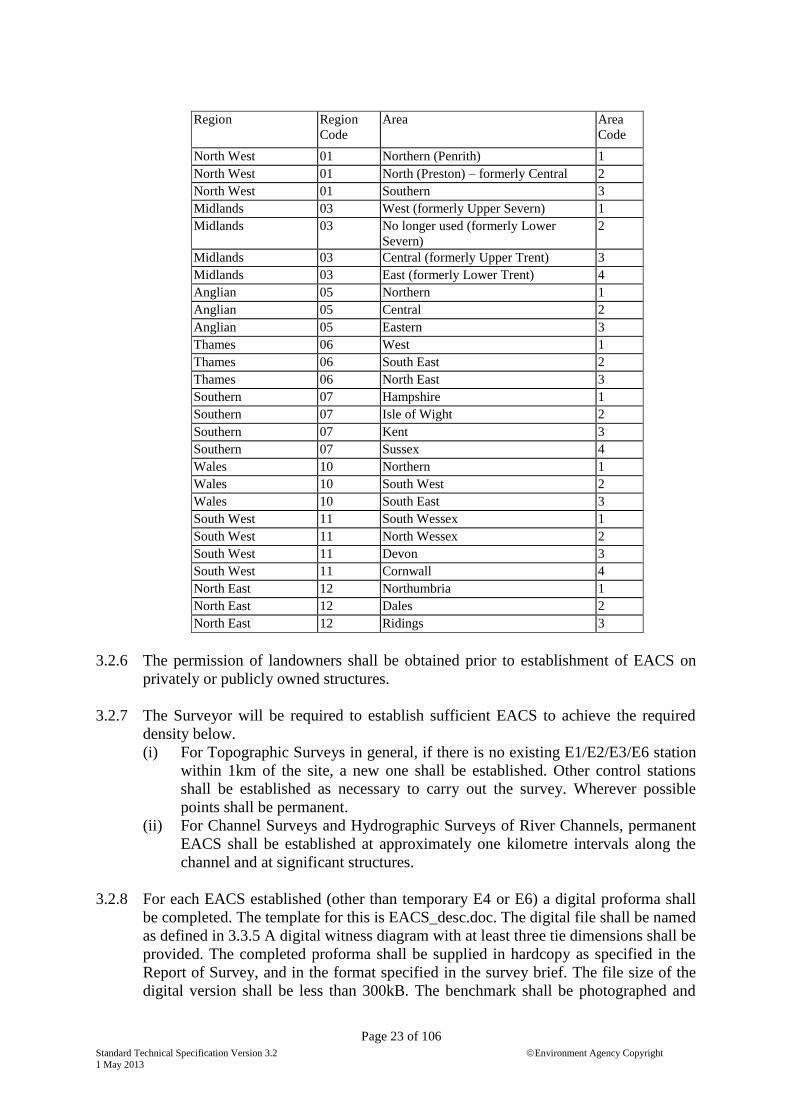
3.2.5 Point numbering System
Note that with the advent of MapEdit, survey control data will be held centrally. The
point numbering system is likely to be changed to accommodate this change and this
paragraph may be superseded.
The following point numbering system shall be used for each control point unless
otherwise specified in the brief:
AABBCDDDD, where AA is the type of point (E1, E2, E3, E4, E5), BB is the Region
code and C is the Area code as given in the list below. DDDD is a sequential number
which will be issued by the regional survey archivist.
Standard Technical Specification Version 3.2 Environment Agency Copyright
1 May 2013
Page 23 of 106
Region Region
Code
Area Area
Code
North West 01 Northern (Penrith) 1
North West 01 North (Preston) – formerly Central 2
North West 01 Southern 3
Midlands 03 West (formerly Upper Severn) 1
Midlands 03 No longer used (formerly Lower
Severn)
2
Midlands 03 Central (formerly Upper Trent) 3
Midlands 03 East (formerly Lower Trent) 4
Anglian 05 Northern 1
Anglian 05 Central 2
Anglian 05 Eastern 3
Thames 06 West 1
Thames 06 South East 2
Thames 06 North East 3
Southern 07 Hampshire 1
Southern 07 Isle of Wight 2
Southern 07 Kent 3
Southern 07 Sussex 4
Wales 10 Northern 1
Wales 10 South West 2
Wales 10 South East 3
South West 11 South Wessex 1
South West 11 North Wessex 2
South West 11 Devon 3
South West 11 Cornwall 4
North East 12 Northumbria 1
North East 12 Dales 2
North East 12 Ridings 3
3.2.6 The permission of landowners shall be obtained prior to establishment of EACS on
privately or publicly owned structures.
3.2.7 The Surveyor will be required to establish sufficient EACS to achieve the required
density below.
(i) For Topographic Surveys in general, if there is no existing E1/E2/E3/E6 station
within 1km of the site, a new one shall be established. Other control stations
shall be established as necessary to carry out the survey. Wherever possible
points shall be permanent.
(ii) For Channel Surveys and Hydrographic Surveys of River Channels, permanent
EACS shall be established at approximately one kilometre intervals along the
channel and at significant structures.
3.2.8 For each EACS established (other than temporary E4 or E6) a digital proforma shall
be completed. The template for this is EACS_desc.doc. The digital file shall be named
as defined in 3.3.5 A digital witness diagram with at least three tie dimensions shall be
provided. The completed proforma shall be supplied in hardcopy as specified in the
Report of Survey, and in the format specified in the survey brief. The file size of the
digital version shall be less than 300kB. The benchmark shall be photographed and

Standard Technical Specification Version 3.2 Environment Agency Copyright
1 May 2013
Page 24 of 106
the photograph shall contain a scale, e.g. levelling staff, to aid interpretation. The
witness diagram shall quote the ETRS89 coordinates for all except E4, E5 and E6
points. National Grid coordinates and orthometric height shall be quoted for all
stations except E5 for which altitude only is required. ETRS89 coordinates are to be
quoted to 0.00001” in plan and 0.001m in elevation. National grid coordinates and
heights shall be quoted to 0.001m. The description shall state if the coordinates and /
or height have been determined by observations based upon E1 / E2 / E3 or E6
stations. The data shall also be presented as standard EA access database records. The
template for this will be found in templates.zip.
3.2.9 Any conservation sites (e.g. SSSI) in the area to be surveyed will be noted in the
Survey Brief together with any restrictions on work on these sites or their boundaries.
3.2.10 No EACSs or any other markings are to be placed into or onto a Listed Building or
structure, nor on to an Ancient Monument. The Survey Brief provides details of any
Listed Buildings and Structures, and other sensitive information known to the
Employer.
3.3 Transformations
3.3.1 All transformations from GNSS derived coordinates to OSGB36 shall be carried out
exclusively using commercially available software packages incorporating OSTN02
and OSGM02, licensed by the Ordnance Survey.
4.0 Vertical Control using sprit levelling
4.1 Spirit level run misclosures are to be assessed by using Clark's Formula of:
For level runs less than 1km: E = 0.005 N (where N = No. of set ups) or,
For level runs greater than 1km: E = 0.012 D (where D = traverse length in
kilometres)
When using digital levels, maximum misclosures should be approximately half the
above values. If not, it is likely that a gross error has been made and further checks
should be carried out on the levelling to prove that there is no gross error.
When using an optical level to observe survey control the level run shall always close
internally either in a loop or by double levelling. When using a digital level with
automatic data recording, it is acceptable to single level between control stations
provided that intermediate points are checked for gross errors using RTK.
For most work, E2, E3 or E6 stations will be used as source control for spirit levelling of
E4 and E5 stations. In these circumstances, wherever possible level runs shall open and
close on different stations.
4.2 Stations must be observed as change points in a level run or as intermediate sights
observed from two different, independent instrument set ups.
4.3 A vertical control diagram shall be produced showing the following:

Standard Technical Specification Version 3.2 Environment Agency Copyright
1 May 2013
Page 25 of 106
(i) Positions of all benchmarks with their type, grid reference, and altitude.
(ii) Lines showing the levelled connections, the direction levelled, distances and
misclosures.
This information will be depicted on appropriate size sheets at 1:10000 or some other
convenient scale OS plan and, if possible, output as a .jpg file and embedded within
the survey report.
4.4 Levelling field notes, reductions and computations are to be included as an annex to
the survey report.
4.4 Only under exceptional circumstances may reciprocal trigonometrical heighting by
used.
4.5 Ordnance Survey Benchmarks (OSBMs)
4.5.1 Each new EACS which is located within 300m of an OSBM shall be levelled from the
OSBM and the result stated in the survey report. This information will permit
comparison to be made between new surveys observed using GNSS and those
previously derived from traditional OS benchmarks and historical data. This is useful
not only for gross error checking for particular surveys but also to build up a picture
of differences over a whole region.
4.5.2 Hydraulic modelling or engineering is frequently based upon surveys undertaken over
a number of years. Altitudes may therefore have been based upon OS benchmarks
and/or GNSS derived heights. Furthermore, the GNSS derived heights may have been
converted to orthometric heights using OSGM91 or OSGM02.
For these reasons, the origin of all height control values shall be clearly stated in the
Report of Survey together with the differences between the value derived by GNSS
and that obtained from the traditional marks. This will allow an informed decision to
be made either to convert levels to the same system or ignore the difference because it
is not significant.
5.0 Horizontal Control using traversing
5.1 Grid
The grid system used shall be indicated clearly on survey drawings and in the survey
report.
5.2 Horizontal Control Network
5.2.1 Where theodolite / total station traversing is used to establish minor control (E4) for
detail surveying, stations established under paragraph 3.3 shall be used as source
control for position and azimuth.
5.2.2 Wherever possible, traverses shall open and close on different control stations. Open
traverses will not be permitted. Bearings shall close to better than 9" x square root of
number of observed angles and shall be adjusted.

Standard Technical Specification Version 3.2 Environment Agency Copyright
1 May 2013
Page 26 of 106
5.2.3 Distances shall be adjusted for grid scale factor and height above spheroid.
5.2.4 Plan misclosure shall be better than 1:20,000.
5.2.5 A horizontal control net diagram shall be produced at 1:10,000 or other agreed scale
for all surveys showing the following:
(i) Positions of all EACS and existing control points with their names and
reference numbers
(ii) Lines showing the observed bearings, distances or GNSS baselines
(iii) Error ellipses for each PGM (Control Surveys – National Grid only)
5.3 Local Grid
Although increasingly unlikely, it is possible that horizontal control for a site will be
established on a local arbitrary grid.
5.3.1 Coordinate values shall be chosen such that the Easting values are not likely to match
the Northing values anywhere on the site.
5.3.2 Local Grid coordinate values must not be such that they may be confused with the
National Grid values.
5.3.3 Local grid shall be orientated approximately to north.
6.0 Survey Monuments
6.1 Permanent and temporary survey control stations shall be established as specified in
3.3.7 and according to good survey practice.
6.2 The type of marker used depends upon:-
(i) survey specification
(ii) site limitation
(iii) ground conditions
(iv) landowner restrictions
Permanent stations shall be one of the following type, in order of preference:-
(i) EA bronze marker or type as agreed with client project manager
(ii) earth anchor
(iii) stainless steel nail (e.g. PK nail)
(iv) cut mark or punch mark
The type of marker used for temporary stations shall be any of the following,
depending upon the above criteria:
(i) wooden peg or stake driven flush to the ground and with a painted top (positioned
only with the permission of the landowner)
(ii) stainless steel nail (e.g. PK Nail) or hilti nail
(iii) cut mark or punch mark
(iv) indelible pen mark on concrete surface

Standard Technical Specification Version 3.2 Environment Agency Copyright
1 May 2013
Page 27 of 106
Temporary survey stations shall never be unmarked, except in exceptional
circumstances which have been agreed with the EA project manager in advance. They
should remain usable for a minimum period of three weeks after delivery of the
survey. Temporary stations should not be numbered for archiving purposes –
designation such as TBM1, 2 etc is adequate. Simple descriptions (photograph) are
required in case the validation surveyor needs to relocate them. The Surveyor can
assume that the validation surveyor can locate the station to within 3m using
navigation-grade GNSS.
6.3 Bronze EA markers shall be installed by drilling and fixing with an epoxy resin type
compound into a stable and permanent structure (Asphalt and kerb stones are not
considered to be stable structures).
6.4 Permission of landowners shall be obtained prior to establishment of markers. At all
times property shall be respected. Services Avoiding Equipment shall be used to
search all areas where any form of ground penetrating station markers are to be
inserted – other than PK nails or EABM studs or like markers. For markers
penetrating more than 0.5m a search must be made with all appropriate service utility
providers. Where temporary pegs are to be installed, they shall penetrate the ground to
a maximum depth of 200mm. In all cases, Surveyor is to carry out a dynamic health
and safety risk assessment.
6.5 The landowner shall be consulted on the installation of all types of marker. Earth
anchors shall be buried to a depth agreed with the landowner (normally 0.1m below
ground level). Wooden pegs must be driven to ground level and then pinned. They
must not be left protruding above ground level as a tripping hazard to humans and
animals. As a general rule the station shall be buried below ground level.
6.6 Only biodegradable paint may be used for marking stations.
7.0 Survey Report
7.1 In the Survey Report the Surveyor shall describe the equipment and method of
observation and adjustment: such as spirit levelling, total station, reciprocal vertical
angles, self recording bar code levels, or GNSS, the maximum length of sights, and
the method of adjustment used, and the validation of the results to confirm that they
are within specification.
7.2 All field books and notes, or direct reproductions of them, and results of all
instrument and field procedure checks shall be submitted as an annex to the Survey
Report.

Standard Technical Specification Version 3.2 Environment Agency Copyright
1 May 2013
Page 28 of 106
SECTION III
TOPOGRAPHIC SURVEYS
1.0 Purpose of Survey
1.1 The purpose of the Survey is defined in the Survey Brief.
2.0 Extent of Survey
2.1 The extent of the Survey is defined by the Survey Brief.
3.0 Mapped Topography
3.1 Detail data shall be delivered using layers, feature codes and symbols as specified in
Section I of this specification.
The maximum distance between points on 3D detail and level strings shall not exceed
the relevant value in paragraph 4.0,
3.2 Plannimetric features
PGMs, EACSs and OSBMs will be plotted as symbols with numbers. Their
coordinates and altitudes will be tabulated in the notes panel.
Where specified in the survey brief the following features shall be surveyed as 3D
point or line features. Points for which the height is not valid shall be given a null
height of -999:
(i) Roads, railways, tracks, footpaths and changes of surface with type.
(ii) Building (plinth line) and structures, including:
Bridges
Weirs
Sluice gates
Level Recorders
Water level gauge boards (include a photograph in survey report
showing at which point the level was taken)
Fishery groynes
All posts and overhead cables. The approximate height of the lowest
point of the cable catenary will be measured and added as a label.
Outfalls: The presence of a flap valve will be indicated as a label.
Service crossings.
(iii) Fences, hedges and other boundaries
(iv) Water-related features including:
Top of banks of all water features

Standard Technical Specification Version 3.2 Environment Agency Copyright
1 May 2013
Page 29 of 106
Water line at the time of survey (to be indicated by a solid line)
Direction of flow of watercourses together with the average water level
at the time of survey
Culvert/Pipe dimensions and invert levels
Beaches, mudbanks, reedbeds and any other features that affect the
width of the channel.
Bridge/culvert soffit levels will be surveyed and added as labels
All underwater features, e.g. concrete/brick aprons, piling alignments,
will be surveyed where identifiable.
(v) Street furniture
(vi) Vegetation including:
The trunks of individual trees equal to or greater than the diameter stated
in the survey brief are to be shown by their bole position and size with
the extent of canopy shown to scale. All other trees will be shown by the
extent of canopy.
Additional vegetation, i.e. shrubs and bushes will be depicted by the
canopy and described accordingly. A centre line and width will
symbolise hedges.
(vii) Service Utilities covers with identification labels
(viii) Retaining walls and banks. Top and bottom of are to be surveyed and offset as
necessary to avoiding crossing strings.
3.3 Levels:
Where specified in the survey brief level strings shall be observed as follows so that in
combination with detail strings observed under para 3.2, an accurate digital terrain
model can be generated from the survey data:
(i) In open featureless areas a regular grid of levels will be surveyed to depict the
terrain at intervals according to the survey scale specified in the survey brief
and the table under Section III, clause 4.0.
(ii) In all other areas sufficient height information will be surveyed in order to
fully describe the topography. Adequate height information will be surveyed to
create a digital terrain model of the survey area sufficient to generate contours
at the interval specified in the Survey Brief.
3.3.1 Spot heights shall be correct to within the limits stated in the survey brief. If a
digital level with automatic data recording is used, an intermediate sight will
have the same status as a back sight or fore sight. If an optical level is used,
intermediate sights to critical points must be observed twice from different
setups.
3.3.2 Spot heights shall be recorded in the following locations except where the ground is
obscured by vegetation or other obstructions:
(i) at salient points such as tops of humps and bottoms of depressions;
(ii) at water level at the time of survey along rivers, streams, ditches, and other
water features, at intervals not exceeding the figure shown in Clause 4.0;

Standard Technical Specification Version 3.2 Environment Agency Copyright
1 May 2013
Page 30 of 106
(iii) along the tops and bottoms of banks, embankments and cuttings and retaining
walls at intervals not exceeding the figure shown in Clause 4.0. Any low
points in raised banks shall be surveyed;
(iv) along the centre lines of roads and tracks at significant changes of gradient and
at intervals not exceeding the figure shown in Clause 4.0;
(v) in open areas, an approximate grid of spot heights shall be recorded at the
interval specified in Clause 4;
(vi) in built-up and wooded areas, spot heights shall be recorded along roads and
tracks and also in open spaces at the average density specified in Clause 4.0.
(vii) additionally, sufficient height information shall be recorded to define the
surface topography and to create a DTM and generate contours at the interval
specified in the Survey Brief.
3.4 Survey containing watercourses shall extend (where safe) approximately 1m (safe
arm‟s length) into the watercourse from the water's edge, unless otherwise stated in
the survey brief.
3.5 For topographic surveys the orientation of the plots on the sheets will be such that the
north points are above the horizontal axis of the sheets.
4.0 Survey Scale table
Survey
Scale
Max size of feature
shown to scale
Interval between spotheights
(Cl 3.3 (i), 3.6 (ii), (iii), (iv),
(v), (vi)
Plan detail to be correct to
within
1:2500 2.5m 50m 0.50m r.m.s.e.
1:1250 1.25m 25m 0.25m r.m.s.e.
1:500 0.5m 20m 0.10m r.m.s.e.
1:200 0.2m 10m 0.04m r.m.s.e.
1:100 0.1m 5m 0.02m r.m.s.e.
5.0 Use of Photogrammetry for topographical surveys
Photogrammetry may be used to survey large sites where access may be an issue for
ground based surveying. Photographic imagery may be needed for record purposes or
where it is necessary to use archive photography to survey a site. The latter may be
needed for studies of illegal waste tips. The accuracy that can be attained using
photogrammetry depends upon the scale of the photography. The following table
gives a guide:
Digital Camera Film Camera
GSD XY Z Photo scale XY(6”&12”) Z(6”) Z(12”)
0.030 0.090 0.045 1:2000 0.100 0.040 0.080
0.040 0.120 0.060 1:3000 0.150 0.060 0.120
0.050 0.150 0.075 1:4000
0.100 0.300 0.150 1:5000 0.250 0.100 0.200
0.150 0.450 0.225 1:7500
0.200 0.600 0.300 1:10000 0.750 0.300 0.600
Accuracies are given in metres r.m.s.e. Courtesy of Blom Aerofilms

Standard Technical Specification Version 3.2 Environment Agency Copyright
1 May 2013
Page 31 of 106
In accordance with the requirements of the survey brief, photography may be obtained
from EA archives or from one of the commercial archives or may be flown to order. If
the surveyor is required to fly new photography, the current RICS specification for
vertical aerial photography shall be used. All new photography shall be digital and
supplied with GNSS and INS data for the exposure position of all photographs.
Imagery shall also be supplied at reduced resolution for quick viewing and a legible
flight diagram shall be supplied. All shall be supplied on media provided by the
Surveyor.
5.1 Where materials are to be supplied by owner, the following will be provided:
(i) Photographic images in digital format either directly from a digital camera or
scanned images from archive film.
(ii) Calibration certificate / data for camera.
(iii) Digital flight diagram clearly showing run and photo numbers on a map
background.
(iv) Output data from GNSS / inertial navigation system
5.2 Surveyor shall establish suitable photo control points sufficient to achieve the plan
and height accuracy requirement of the survey with redundancy to detect errors. The
following refers to photo points on film. The same principles can be applied to digital
imagery.
5.2.1 For planimetric. control, the surveyor shall identify suitable clearly defined points
from the aerial photography. If GNSS is to be used to survey a point's position, the
point must be suitable for GNSS survey. The photography shall be pricked, ringed
and numbered on one photograph on which it appears and a record sheet prepared.
These points shall be coordinated to E4 standard.
5.2.2 Each height control point shall be pricked, ringed and numbered on one control print
in each strip. A photo point record sheet of approved design (to include the photo run
and frame number) shall be completed at each point. Height control points are to be
observed along the edges of the outer runs of photography and in the lateral overlap
between runs at intervals stated by the surveyor in his proposal. The interval between
height control points shall be sufficient to achieve the height accuracy required, to
prove the quality of control by self-checking and eliminate the possibility of gross
errors.
5.3 It is expected that aerial triangulation will be used to confirm the reliability and
identification of both planimetric and vertical control and to ensure that the
connections between models are within acceptable tolerances. The final report shall
include a summary of the aerial triangulation results listing the mean residuals and the
ten largest discrepancies at plan, height and minor control points. All rejected points
shall be listed. The tolerances set for orientation of the individual photo models for
plotting shall be stated and evidence presented to confirm that these tolerances have
been achieved. If the Surveyor does not intend to use aerial triangulation, he/she
should provide a very detailed and convincing description of the methods of
observation, adjustment and validation that he/she proposes to use, to ensure that the
specified accuracy will be achieved and confirmed using alternative test procedures.

Standard Technical Specification Version 3.2 Environment Agency Copyright
1 May 2013
Page 32 of 106
5.4 If the survey borders on to a previous photogrammetric survey, edge matching and
data merging with existing data shall be included in this contract.
5.5 Unless otherwise stated in the survey brief, for photogrammetric surveys only, the
Surveyor is not required to undertake any field verification. Any height points on the
DEM grid or strings that may not conform to the specified accuracy, because the
ground surface is not visible on the photography, shall be coded separately in the data
files as "unreliable" and shall be indicated on the Preliminary Plots and in the digital
data.
5.6 Where a watercourse is incised and passes under a bridge (deck nominally at ground
level), the visible water lines shall be connected as null string levels under the bridge.
Null levels shall be set at -999m.
5.7 The Surveyor shall include the following information, results and materials with the
survey report:
(i) Photo control prints with plan, height and minor control points pricked, circled
and numbered, with photo point record sheets.
(ii) Photo control and aerial triangulation results, including summaries of aerial
triangulation residuals, and a schedule of coordinates and heights of plan,
height and minor control points. To be supplied in digital format for archiving
and retrieval using standard software.
(iii) Schedule of source control and new control established for the survey.
(iv) Calibration reports for field and photogrammetric instruments.
(v) Key Plan and sheet layout at suitable scale in EA sheet format.
5.8 Interpolation of additional points along break lines for flood plain surveys only
5.8.1 Additional points shall be interpolated along break lines for the entire project or (with
the agreement of the Client project manager) sub-projects of manageable size.
5.8.2 Additional points are to be interpolated along all break lines (except null strings)
plotted under Clause 3.2. These points are required because many programs that
create triangular irregular networks (TIN) do not recognise linear features as break
lines to control the generation of the triangular mesh. By interpolating additional
points along break lines, TIN programs are forced to recognise them. Unless
otherwise specified in the brief, the distance between interpolated points shall be a
maximum of 1.5m.
5.8.3 The interpolated points shall be stored in space-delimited text files of E, N, Ht with
the file name AAAABint.txt, where AAAA is the job number and B is spare character
which is available if the project is sub-divided into sub-projects.
5.8.4 The observed points on break lines and observed spot heights shall be stored in text
files with the file name AAAABobs.txt.

Standard Technical Specification Version 3.2 Environment Agency Copyright
1 May 2013
Page 33 of 106
5.8.5 These points shall be imported into an autocad drawing with file name
AAAABpts.dwg as 3d POINT entities. Points from AAAABint.txt shall be stored in
layer name interp_pts. Points from AAAABobs.txt shall be stored in layer name
obs_pts.
6.0 Use of Total station observations for topographical surveys
6.1 Lines of sight from tacheometric survey where the height coordinate will be used in a
3D string shall not exceed 150m unless the surveyor computes heights using earth
curvature and refraction corrections that correct for these errors within the accuracy
required of the survey.
6.2 When used to survey soft features, such as top of silt in a river bed or sand surface on
a beach, the prism pole must be fitted with a plate to prevent the tip of the pole
sinking into the surface.
6.3 Surveyor shall observe at least one detail point on each setup that is common with a
detail observation from another instrument set up and quote the coordinate
comparison in the survey report.
7.0 Use of RTK and network RTK for topographical surveys
Base and rover RTK and network RTK techniques may only be used under site
conditions for which they are suitable - ie clear sky view and no multipath and using
equipment that can receive signals from all operational GNSS constellations.
7.2 When heights are surveyed using Real Time Kinematic GNSS (RTK) the accuracy
shall be monitored by observing points of known height established for the purpose at
intervals during the survey day. The results of these observations shall be logged with
their date and time and the record submitted with the Report of Survey. The
observations shall – as a minimum – be taken before commencing surveying and as
the last observation at the end of the survey day. Following a loss of initialisation and
re-initialisation on the fly or if the surveyor is unsure that the equipment is operating
properly, he shall stake-out a previously observed point and take an observation on it
to check the re-initialisation. When necessary the instrument shall be powered-down
in order force re-initialisation. If any observation is found to vary from the known
height by 30mm or more then all data observed since the previous check will be
abandoned and resurveyed. When Kinematic GNSS data collectors are used for
profile measurement they will be set to a horizontal precision of 15mm and a vertical
precision of 20mm.
7.2 For network RTK, surveyors shall in addition follow the guidance published by the
Survey Association (www.tsa-uk.org.uk) using a minimum observation window of 5
seconds. When necessary the instrument shall be powered-down in order force re-
initialisation.
8.0 Use of terrestrial laser scanning for topographical surveys
8.1 Terrestrial laser scanning is currently used mainly for deformation monitoring surveys
of structures and for beach monitoring surveys. Scanners can be mounted either from

Standard Technical Specification Version 3.2 Environment Agency Copyright
1 May 2013
Page 34 of 106
static instrument set-ups or in kinematic mode when mounted on a moving vehicle
(car or boat). Observations from static setups are more accurate than those from a
moving vehicle.
Scanning equipment must have been calibrated within the previous 12 months and
Surveyor must provide a calibration certificate or satisfactory records to demonstrate
that it achieved the required precision and accuracy.
Surveyors must have attended adequate training in use of the laser scanning
equipment, survey control for scanning, point cloud registration and processing point
cloud data. They must be familiar with health and safety issues concerning scanners
and be capable of carrying out dynamic H&S risk assessments.
8.2 Scanning from tripod set-ups
Tripods are normally used for static set ups but it is possible to mount the scanner on
a vehicle that is stopped at successive scan positions. If this method is used, it is vital
to ensure that the vehicle remains sufficiently stable during the scanning process.
The primary means of survey control for scanning shall be surveyed targets in the
scans and surveyed scan positions. These points shall be surveyed in accordance with
Section II of these specifications. Surveying for EA purposes will nearly always be
conducted from stable platforms, so if available for the scanner concerned, the dual
axis compensator shall be switched on. Control must be located so as to provide
strong position fixing in three dimensions. There must be sufficient redundancy in the
survey control to enable errors to be detected and corrected as well as to achieve the
required accuracy. In addition, there shall be an overlap of at least 20% between scans
so that cloud-to-cloud registration can be used as an independent check. The results of
registration shall be quoted in the survey report.
Sufficient scans shall be observed to describe the object to be surveyed and avoid
voids in the data.
Each point in the point cloud shall be assigned RGB colour values from digital
imagery obtained concurrently with the scan data.
Surveyor shall retain raw scan data for at least six years and make available free of
charge to the client on request.
Each raw scan shall have associated metadata as shown in Section 7.4.3 of English
Heritage Standard Specifications for the Collection and Archiving of Terrestrial
Laser Scan Data. Metadata records shall be supplied for all raw scans.
Surveyor shall provide control and registration information for all raw scans to the
site coordinate system. The residuals from registration shall be provided.
Registered and geo-referenced scan data shall be delivered in generic .las data format
on media as agreed with the client. Associated metadata shall be supplied in
accordance with Section 7.4.4. of English Heritage Standard Specifications for the
Collection and Archiving of Terrestrial Laser Scan Data

Standard Technical Specification Version 3.2 Environment Agency Copyright
1 May 2013
Page 35 of 106
8.3 Scanning from moving vehicles
Scanning from moving vehicles differs from scanning from tripods in that the control
for the survey comes from GNSS receiver(s) and inertial measurement units (IMU)
mounted on the vehicle near the scanner. The GNSS receiver operates in kinematic
mode (base and rover or network) to measure the position of the vehicle. As with all
GNSS, its operation and accuracy are affected by obstructions in the sky view and
multipath. The IMU measures the attitude of the vehicle and can be used for relative
position fixing. When close-coupled with the GNSS, the IMU can provide position-
fixing through areas where there are insufficient GNSS signals and can assist the
GNSS in „finding‟ satellites after emerging from these areas. The errors of the
kinematic GNSS and IMU will be propagated to the error of points in the scanned
point cloud. Surveyor is to declare the specifications of the equipment to be used and
the software connection between the GNSS and IMU.
If only one scanner is used, there will be voids in the point cloud. These can be
mitigated by using two or more scanners on the vehicle that point at different angles
forwards and backwards.
Surveyor shall provide documentary evidence that his mobile laser scanning system
has been tested under similar ground and sky view conditions to those that will be
experienced in the area to be surveyed and produces point cloud data to the accuracy
required.
Surveyor shall provide details of the observations and calculations used to determine
the relative positions of the scanner and GNSS receiver(s) and synchronisation of the
scanner, GNSS and IMU. Surveyor shall document and provide all survey data used
to position and orientate the vehicle during the survey.
The surveyor must „ground truth‟ the survey by surveying, using GNSS RTK or
equivalent means, objects in the scan data at a maximum of 500m intervals along the
vehicle route. The comparison of three dimensional coordinates shall be provided in
the survey report.
Mobile scanning is still relatively new technology. The client reserves the right to
carry out a proving survey. If the results indicate that the survey has not met accuracy
specifications, it will be rejected.
Point cloud data shall be supplied in .las format.

Standard Technical Specification Version 3.2 Environment Agency Copyright
1 May 2013
Page 36 of 106
SECTION IV
CHANNEL SURVEYS
0.0 The client or his representative shall walk the section of river to be surveyed with the
surveyor. This is necessary to:-
Agree detailed requirements where the surveyor might otherwise be uncertain.
Ensure that the surveyor is aware of critical data which might not be obvious to
him / her.
Establish a level of trust and communication between the surveyor doing the work
and the client who will be using the data.
1.0 Presentation and Format of Data
1.1 Unless specifically excluded from the survey brief, data is to be delivered in EACSD
format. The EACSD format is a universal transfer format and is defined in file
EACSD_v3_2.doc in NatSpecTemplatesV3.2.zip. Note that there is a field for time of
survey in the header for each section. This information is required for model
calibration purposes. Surveyor shall ensure that the time is set correctly in instruments
before commencing the survey.
The Surveyor is also to provide digital channel survey data in other formats as
specified in the survey brief. These may be proprietary to particular flood modelling
software packages. It is recommended that, certainly during 2013, data is supplied in
EACSD format and in the input data format for the software that will be used for the
flood modelling project.
In addition, surveyor shall provide a comma-delimited text file of point number,
Easting, Northing, Height for all as-surveyed points before any adjustments are made
to, for example, snap on to cross-section lines.
1.2 Data is to be presented graphically on key plan / section location maps, cross-sections,
structure sections and long sections all presented in Autocad .dwg format all in
accordance with Section I. Example drawings are included in
NatSpecTemplatesV3.2.zip and prefixed SectionIV_.
1.3 The completed plots will include the Environment Agency standard legend that will
be used in conjunction with the title box and frame (supplied in. DXF).
1.4 Left Bank and Right Bank are defined as viewed downstream.
1.5.1 When congested data would cause over-writing of the coordinates under plotted
sections, the descenders should be cranked to allow the values to be plotted without
over printing.

Standard Technical Specification Version 3.2 Environment Agency Copyright
1 May 2013
Page 37 of 106
1.6 All cross-sections, whether open channel or structure, shall be viewed looking
downstream. A note: “All cross-sections are viewed looking downstream” is to be
included on each sheet of cross-sections.
2.0 Open Channel Cross-section
2.1 Cross-sections are to be surveyed normal to the centre line of the channel at the
interval specified in the Survey Brief and/or as shown on the contract mapping. On
tightly meandering channels, cross-sections shall be located where the channel is
running parallel with the valley. This removes the need for „dog-leg‟ cross sections
across a flood plain.
2.1.1 Structures not falling at the specified interval are to be surveyed, unless varied in the
Survey Brief.
2.1.2 Cross-sections will be surveyed where the channel significantly changes width.
2.2 Where it is not practical to survey a section at the prescribed position or interval the
position of the section may be moved. However, the interval between two adjacent
sections shall not exceed the prescribed interval.
2.3 Cross-sections are to be surveyed viewed downstream and the origin or zero chainage
of the cross-section must be established on the left bank (LB) of the channel viewed
downstream. However, where a section is only required through the Right Bank, the
origin or zero chainage shall be located on the waterside of the bank, i.e. in the
channel.
2.4 Each individual structure cross-section will be given a relevant title included in the
section header. Open Channel Sections should not normally have a title.
2.5 In addition to cross-sections through the channel, cross-sections will extend from the
channel to the true land level on each side and at least 5m beyond the bank top unless
mentioned otherwise in the Survey Brief. Where there is a defence, trees or
bushes/shrubs line the channel the section shall extend to 5m beyond the vegetation,
but no more than 50m from the channel. Beyond the extent of the cross-section, a
general indication of the ground form will be given as a label e.g. “flat”, “rises
steeply”. The point used for the longitudinal section bank top shall be indicated on the
plotted cross-section.
Note: Where a bank top is raised above the surrounding ground (flood plain), the crest is
defined as the line along the bank top over which water will spill from the river onto
the surrounding ground. Where there is no raised bank, the crest is the point marking
the change of gradient from surrounding ground to eroded channel.
Note: Where a flood defence is present on the cross-section, this should be surveyed as a
separate string. A flood defence is defined as an object (generally an embankment or
wall) which provides a flood protection benefit.
2.5.1 Points along the cross-section are to be surveyed at an interval which accurately
depicts the shape of the channel. For open channel sections, the drawn line of the
Standard Technical Specification Version 3.2 Environment Agency Copyright
1 May 2013
Page 38 of 106
cross-section shall be correct to better than +/- 0.1m in height allowing for up to 0.2m
movement along the section line. For structure details, the drawn line of the cross-
section shall be correct to better than +/- 0.04m in height allowing for up to 0.04m
movement along the section line.
2.5.2 Bushes, trees, fences and buildings adjacent to the channel cross-section are to be
shown as symbols – not true to scale.
2.5.3 Buildings are to have their floors or damp-proof course level indicated. Where they
cannot be determined the threshold level shall be recorded. Buildings will be labelled
with name and/or number, type and whether damp-proof course exists.
2.5.4 Fences will be labelled with their type and height.
2.5.5 Road crossings will be labelled with name and/or number.
2.5.6 The treatment of secondary channels around islands or shoals will be defined in the
brief.
2.6 Bed Levels
2.6.1 Bed levels will be measured directly whenever and wherever possible. Where direct
measurement is impossible, where, for instance, the water depth is too great or other
causes make it impractical, then it will be sufficient to read the depth of water against
a staff or to use echo sounding and to relate these readings to a measured water level.
2.6.2 Modellers are generally required to base their models on the current state of the river
bed. Therefore, by default, the bed level shall be taken on top of silt (soft bed), and a
note added to the drawing to indicate that only soft bed has been shown. Hard bed
levels, at base of silt, shall be surveyed if specified in the survey brief.
2.6.3 The nature of the bed material will be recorded and plotted on the section in
simplified form, e.g. 'Gravel‟ based on the material and vegetation types detailed in
EACSD_v3.2.doc. Surfaces outside the water area will also be labelled.
2.7 Surveying methods
Detail surveying shall follow the principle that all observations shall be subject to self
checking and independent checking to ensure that gross errors are detected. This
paragraph is intended to reflect this principle.
For all open channel sections, a wooden peg (temporary E4 station) shall be
established as the base point for every section at a suitable place on the river bank.
The E4 stations shall be surveyed as specified in Section II.
The surveyor shall use an appropriate surveying method for the section concerned. If
the cross-section is surveyed using total station techniques the base point shall be used
for the total station set up. The surveyor may use another E4 station or a remote RO to
established orientation. Observations must be checked for gross errors (eg instrument

Standard Technical Specification Version 3.2 Environment Agency Copyright
1 May 2013
Page 39 of 106
or pole height errors). The checking method(s) used shall be documented in the
survey report.
If there is a clear sky view and the accuracy specification can be met, GNSS RTK or
network RTK detail survey methods may be used. The base point peg shall be
observed at the same time as the cross-section using the same technique. The
comparison between RTK level and control level of the E4 base point shall be
tabulated in the survey report.
2.8 National Grid Reference and cross-section Orientation
2.8.1 Channel Surveys may be merged with photogrammetric or LiDAR surveys of the
flood plains and therefore positional accuracy must be of the same order. Each
Section Zero Point shall be monumented with a wooden peg and surveyed to E4
standard. Section orientation shall be determined by observations to another E4
station – not using a compass.
Only in exceptional circumstances and by prior agreement will it be acceptable to
position sections from OS mapped detail and use a compass to determine orientation.
2.8.2 The section data will also be plotted against an Ordnance Survey background to give
the true position of the section. See also 9.2.1.
2.9 Cross-section Reference Numbers
2.9.1 Cross-sections will be numbered as described in the Survey Brief.
2.10 Scale
2.10.1 Scales are defined in the Survey Brief.
2.11 Merging Data from Previous Surveys
2.11.1 Any requirement for merging data with data from a previous survey will be noted in
the Survey Brief. Validation checks shall be made between new and old survey
control. Data shall be merged so that the correct sequence of chainage across the
section and along the channel is maintained. A note of this shall be added to the cross-
sectional plot.
2.11.2 Cross-sections from a previous survey shall be updated if there is a significant change
(e.g. a new structure).
2.12 Flood Plain Sections
2.12.1 If flood plain cross-sections are required, this will be noted together with the interval
in the Survey Brief.
2.13.2 Sections will be plotted at the scales defined in the Survey Brief.
Standard Technical Specification Version 3.2 Environment Agency Copyright
1 May 2013
Page 40 of 106
2.12.3 A Flood Plain Section will be taken normal to the centre line of the valley and not
necessarily at right angles to the centre line of the channel. Because of this, flood
plain sections may appear 'dog-legged' on the key plan. These sections may be defined
on the contract mapping.
3.0 Structures
3.1 Unless otherwise stated in the survey brief a section shall be surveyed on the upstream
side of each structure which significantly affects the river flow at bank-full flow
condition. Structures include bridges and culverts (see 4.0), weirs, mills, pipe
crossings (greater than the diameter stated in the survey brief) and impounding
structures of any kind. Natural features, which act as structures, such as rock outcrops,
shall also be included. Structures which are not to be surveyed shall be photographed.
The photographs and NG coordinates of the position of the structure shall be included
as an appendix to the survey report. If there is any doubt, the Surveyor should consult
the Employer to confirm whether a section is required.
3.2 All pipe crossings, including those too small to require a cross-section to be taken,
shall be shown on the longitudinal section, along with critical levels and dimension.
Overhead power and telephone cable crossings are to be noted and their position and
their clearance height over the centreline of the channel plotted on the longitudinal
section. Underground crossings (water, gas, power etc.), where evident on site, are
also to be noted and their position plotted on the longitudinal section.
3.3 GNSS is only suitable for taking detail observations on structures if the pole can be
held vertically over the point required and the antenna is not obstructed by a poor sky
view or by the structure itself. Generally, observations should be made using a total
station.
4.0 Bridges and Culverts
A bridge is defined as a permanent structure spanning the channel. Cross sections of
temporary and ad hoc crossings are not required unless specified in the Survey Brief.
However, such crossings shall be shown on the longitudinal section.
4.1 A complete elevation of the upstream side is to be taken with particular attention paid
to the measurement of the bridge openings and flood arches. Surveyor shall survey the
bed level where the structure enters the bed. Details of any bridge piers will also be
shown. Soffit, invert and springing levels will be added as labels. The structure
section shall include banks behind the structure.
4.2 The downstream elevation will be presented as viewed looking downstream and is
required to be surveyed when specifically requested or where it is different from the
upstream side. Even when a Downstream elevation is not required, the downstream
soffit, top of parapet, invert, bed level and bank crests are to be measured and added

Standard Technical Specification Version 3.2 Environment Agency Copyright
1 May 2013
Page 41 of 106
to the longitudinal section. This information is also to be shown „ghosted‟ on the
upstream elevation drawing if requested in the survey brief.
4.3 The length of the bridge tunnel is to be measured parallel to the watercourse and this,
together with hard inverts on aprons and their extent, added as labels on the cross-
section plot.
4.4 Where a bridge changes section within its length and that change is significant, then
an additional section shall be surveyed at the change.
4.5 At bridges, the channel section surveyed will be assumed by the modellers to be
representative of the reach. Where the bridge structure constricts river flow, the open
channel section details should be observed where they are representative of the reach
– not necessarily up against the structure. See paragraph 9.0 for a decision tree
indicating open channel cross-section survey requirements up and downstream of
structures.
4.6 Where a structure is not normal to the channel but is skewed, the skew span will be
measured and presented on the drawings, together with the approximate angle of
skew, this being the angle between the bridge face and a line normal to the channel.
The length of the bridge tunnel will then be the channel length through the bridge
parallel to the watercourse, not the distance at right angles to the roadway.
4.7 Where a structure extends 10m beyond the top of the bank, then the complete
elevation will be surveyed with its cross-section. Where a bridge spans the flood
plain, then all relevant flood arches (and other openings that could take flood water,
such as pedestsrian subways) must be included in the cross-section. If the cross-
section is excessive then a plot of the immediate channel will be drawn to the
specified scale. The complete cross-section will be plotted at a reduced scale and
provided on a separate sheet, cross-referenced to the channel plot.
4.8 When a culvert is longer than the section interval defined in the Survey Brief a cross-
section will be taken at entrance and exit.
4.9 Under no circumstances shall the Surveyor enter a confined space which has not been
notified to him/her in the Brief and for which no proper procedures have been
adopted.
5.0 Weirs and Drop Structures
5.1 A weir is defined as a permanent or temporary structure that impounds a head of
water at normal summer levels greater than the height defined in the Survey Brief.
A drop structure is defined as a natural or man-made step in the channel bed that will
be surveyed, as defined in the Survey Brief.
5.2 A cross-section will be taken across the crest of the weir, viewed downstream with
structure details incorporated as shown in the Survey Brief. For labyrinth weirs and

Standard Technical Specification Version 3.2 Environment Agency Copyright
1 May 2013
Page 42 of 106
other weirs that do not cross the river in a straight line perpendicular to the river, the
actual length of the weir shall be stated clearly on the cross-section drawing.
Additional cross-sections will be taken immediately upstream and downstream of the
weir crest, viewed downstream and normal to the centreline of the channel as shown
in the Survey Brief.
5.3 In the case of moveable gates or boards, the gate sill will be considered as the crest of
the weir.
5.4 Levels are to be taken on the tops of all gates and moveable boards. Where gates are
open, levels are to be taken on the bottom of the gate. Where possible the maximum
opening height of the gate is to be measured and noted on the drawing.
5.5 Levels across the weir crest or on aprons shall not be taken as soundings.
5.6 Moveable control structures, such as weir gates, should be distinguished from fixed
structures such as sills and weir crests, by marking them with a diagonal cross.
5.7 A longitudinal section through the centre line of the weir (but NOT through a drop
structure) will be produced in cross-section format showing all structure details, such
as positions of gates and bridge crossings, extending both upstream and downstream
to the natural riverbed. This will be plotted viewed from the Left Bank.
5.8 Longitudinal sections through weirs are to be numbered with the same section number
as the downstream elevation, suffixed with an alpha character (e.g. N.NNNA).
5.9 The longitudinal section will show the following information:
(i) upstream water level
(ii) upstream bed level
(iii) weir crests, gates and any bridge structures
(iv) upstream and downstream extent of any apron
(v) downstream water level
(vi) downstream bed level, including maximum depth of scour hole where it is safe
to obtain levels
(vii) water and bed levels at the tail of any weir pool
5.10 An additional cross-section will be taken both upstream and downstream of the weir
where the channel returns to its normal cross-section and is free from the influence of
deposition and scour.
5.11 If no E5 or levelled E4 station exists at, or within 100m of, the weir site one shall be
established during the course of the survey. If there are many weirs close together,
this requirement may be varied by agreement with the Client project manager.
6.0 Mills

Standard Technical Specification Version 3.2 Environment Agency Copyright
1 May 2013
Page 43 of 106
6.1 The downstream and upstream elevations are to be measured as for bridges with
additional sections taken at significant changes in the section of the mill thorough.
6.2 The internal control structures are to be measured as for Weirs (Part II, Section IV,
Clause 5.0).
6.3 Gate opening heights are to be measured if practical.
7.0 Locks
7.1 Open channel cross-sections shall be surveyed immediately up and downstream of the
lock chamber where the channel regains its normal width, at the lock gates and at the
mid point of the lock chamber.
7.2 Cross-sections at the lock gates shall be taken through the pivot guides of each lock
gate, upstream and downstream. All sill apron levels will be detailed together with the
controlling mechanism and individual gate levels.
8.0 Natural Constraining Features
8.1 Features such as rock formations, which cause gradient changes or affect water levels,
are to be treated as weirs.
8.2 Changes in water level gradient over shoals and aprons, and sudden changes in bed
level are to be measured and added to the longitudinal section.
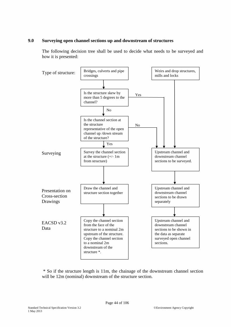
Standard Technical Specification Version 3.2 Environment Agency Copyright
1 May 2013
Page 44 of 106
9.0 Surveying open channel sections up and downstream of structures
The following decision tree shall be used to decide what needs to be surveyed and
how it is presented:
Type of structure:
Surveying
Presentation on
Cross-section
Drawings
EACSD v3.2
Data
* So if the structure length is 11m, the chainage of the downstream channel section
will be 12m (nominal) downstream of the structure section.
Bridges, culverts and pipe
crossings
Is the structure skew by
more than 5 degrees to the
channel?
Is the channel section at
the structure
representative of the open
channel up /down stream
of the structure?
Draw the channel and
structure section together
Weirs and drop structures,
mills and locks
Upstream channel and
downstream channel
sections to be drawn
separately
Upstream channel and
downstream channel
sections to be surveyed.
Survey the channel section
at the structure (+/- 1m
from structure)
Copy the channel section
from the face of the
structure to a nominal 2m
upstream of the structure.
Copy the channel section
to a nominal 2m
downstream of the
structure *.
Upstream channel and
downstream channel
sections to be shown in
the data as separate
surveyed open channel
sections.
Yes
Yes
No
No

Standard Technical Specification Version 3.2 Environment Agency Copyright
1 May 2013
Page 45 of 106
10.0 Longitudinal Section
10.1 Chainage
10.1.1 Each cross-section shall be provided with a chainage. This is the distance along the
centre line of the channel from the downstream extent of the survey. The centre-line
shall be digitised from the OS 1:2,500 / 1:1,250 map. It shall be supplied as a polyline
in a separate layer and presented on the Key Plan. The cross-sections shall be plotted
on the Key Plan from actual surveyed section points, and their centreline chainage
deduced by measurement along the centreline of the mapped watercourse. Zero
chainage will be at the downstream extent of the watercourse unless otherwise
specified in the Survey Brief.
10.1.2 Running chainages along the watercourse shall be noted on the levelling sheets, with
the start point and direction of work clearly defined. Chainages shall be noted at
boundaries, ditches, drainage pipes and other identifiable features, indicating on
which bank these features appear. Cross-section chainages will also be noted and
clearly referenced.
10.2 Key Plan
10.2.1 A digital key plan based upon OS 1:2,500 or 1:1,250 data, will be produced for each
longitudinal section to show the cross-section positions (see 9.1.1) and watercourse
centre-line. Whenever possible this plan will be incorporated into the same sheet as
the longitudinal section. When so incorporated it will be aligned to match the
longitudinal section in Autocad paper space mode. It is acceptable for the plan to be
inverted. It will be provided with north point and grid coordinates.
10.2.2 In addition the river centre-line shall be presented as a digital polyline created in a
format suitable for input to ArcView.. It will be provided with the following
attributes.
Field Name Field Type/Width Remarks
Polyline_ID String max 9 characters nnnnn_nnn (Not included in ArcView
Format).
Data Source “ max 30 “” eg. „Survey‟
Surveyor “ max 30 “” Company Name
Consultant_Ref “ max 30 “” Surveyor‟s reference
Client_Ref “ max 30 “” Agency Job Number
Date “ max 30 “” ` Date of survey
Channel “ max 30 “” Watercourse name
Surveyors without access to ArcView may render the polyline in AutoCAD as a file
named CLXXXXXX.dwg where XXXXXX is the job name. The attributes shall be
presented in Access format utilising the relevant parts of the Land Owner Template
provided in Part IV.

Standard Technical Specification Version 3.2 Environment Agency Copyright
1 May 2013
Page 46 of 106
10.3 Content/Presentation of Longitudinal Section
10.3.1 Where a longitudinal section is required it will be produced from the recorded data at
the scales shown in the Survey Brief.
It will show the following:
(i) The deepest bed level at each section, both hard bed (solid) and silt line
(pecked).
(ii) The water level at each section.
(iii) The bank crest levels derived from crest point levels shown on the cross-
sections, the left bank as a pecked line and the right bank as a bold line.
(iii) The extent and level of any concrete sill or apron together with appropriate
label (i.e. nn.nn).
(iv) The section number and chainage of each section and the altitudes of each of
the plotted points. The chainage shall be quoted to the nearest metre except
when the scale of the survey makes it appropriate to quote the chainage to
decimetres.
10.3.2 Each bridge, overhead crossing, weir, mill etc. will be shown on the longitudinal
section with its critical levels (soffit, invert, deck, crest etc.) indicated labelled
invert, soffit. Where soffit and invert levels have been surveyed at both upstream
and downstream elevations both will be labelled on the longitudinal section.
10.3.3 The water line for each day will be labelled at its limits with the appropriate date.
10.3.4 Tributary channels are to be measured and depicted where they cross the bank crest
line. Three points are usually adequate to describe a ditch, but more should be taken
where the tributary is large.
Where the feature takes the form of a controlling structure such as a weir, sluice or
overfall, then a complete cross-section will be measured.
The tributary name will be added as a label.
10.3.5 Field drains and other infall structures greater than the diameter stated in the survey
brief are to be measured with either invert or soffit surveyed. Individual diameter
sizes and appropriate bank indicator shall be added as labels together with either a
soffit or invert level. The existence of a flap valve shall be added as a label.
10.3.6 Side weirs, etc, which are not part of the main channel shall be shown with critical
levels as variations to the bank crest.
10.3.7 Where changes in the levels of bank, bed or water level occur between cross-sections,
these changes are to be measured and added to the longitudinal section. The
longitudinal section should represent an accurate and complete profile of the channel
to ensure that low spot and level changes are identified. See 9.5.
10.3.8 To aid clarity insets shall be used at locations where detail is dense e.g. Mills.

Standard Technical Specification Version 3.2 Environment Agency Copyright
1 May 2013
Page 47 of 106
10.4 Gaugeboards
10.4.1 Any gaugeboards encountered in the course of a channel survey shall be surveyed.
The position shall be determined to +/- 2m and the height of a graduation on the board
to within 10mm with respect to the nearest survey control station. The gaugeboard,
with reference number, shall be shown on the location map and the reference number,
E, N, graduation value and surveyed height shall be tabulated in the survey report.
10.5 Flood bank levels
10.5.1 River banks that are raised above the surrounding ground and other linear raised
features are classified as flood defences. A flood defence is defined as an object
(generally an embankment or wall) which provides a flood protection benefit. Known
flood defences that are required to be surveyed will be indicated on the contract
mapping. Where the surveyor comes across a significant defence that is not shown on
the contract mapping, he shall contact the Client project manager to ask if it should be
surveyed.
10.5.2 The crest level of these flood defences shall be surveyed at 25m intervals and at any
low points. Surveyed points shall be accurate to within 1m in plan and 0.02m r.m.s.e
in height above ODN. The crest level string data shall be supplied as separate comma
separated ASCII data in the long section data points of the EACSD format. Raised
river bank data shall be incorporated within the long section. The „crest‟ is defined as
the level at which water will flow over the defence to lower ground beyond.
10.5.3 The crest level of wall defences shall be taken on the top of coping stones, the lower
side of coping or at both locations, as specified in the survey brief.
11.0 Photography – additional to Section I
Surveyor to take digital photographs of each open cross-section location and of each
structure and will include a levelling staff to indicate scale. Both the upstream and the
downstream faces of bridges will be photographed. Photo files are to be named in
accordance with the EACSD specification and provided with labels quoting the
section number, name of the bridge and road number if one exists plus the chainage to
the face photographed.
The photo file resolution should be limited 1600x1200 to reduce file sizes. 360 degree
photos or video files can also be referenced, if specified by the Client.

Standard Technical Specification Version 3.2 Environment Agency Copyright
1 May 2013
Page 48 of 106
SECTION V
BUILDING THRESHOLD SURVEYS
1.0 Materials supplied by the Employer
1.1 The Employer will supply, in addition to the standard items:
(i) Explanatory letter to residents (see thresholdpermitletter.doc in templates.zip)
(ii) Schedule of, or plans showing, properties to be surveyed
(iii) Base plans for presentation of threshold data
(iv) Tabular formats for recording threshold and property data.
2.0 Materials supplied by the Surveyor
2.1 The Surveyor is required to deliver the explanatory letter to residents giving at least 7
days notice of entry to property.
3.0 Threshold Data
EACS established for threshold surveys shall be surveyed to the standards specified in
Section II. Threshold survey levels shall be correct to +/- 10mm with respect to the
nearest permanent EACS. If a digital level with automatic data recording is used, an
intermediate sight will have the same status as a back sight or fore sight. If an optical
level is used, intermediate sights to critical points must be observed as a change point
or twice from different setups.
3.1 Levelling of thresholds shall open and close on different EACS or incorporate a
different EACS / check station within the level loop. The height of the main
thresholds of each property listed is to be measured above Ordnance Datum. The
definition of 'threshold' is shown in the diagram below.
Diagram Detailing Threshold

Standard Technical Specification Version 3.2 Environment Agency Copyright
1 May 2013
Page 49 of 106
3.2 Unless noted otherwise in the survey brief, threshold levels and property details shall
be presented in the standard Excel spreadsheet format (Threshlev.xls). The file shall
be named jobno_threshlev.xls. The data or data format supplied by the client in
threshlev.xls must not be changed without prior agreement with the client‟s project
manager.
3.3 The survey brief will state if threshold levels are required only at the front door of
each property or whether the threshold of all external doors is required. Ground level,
Air brick and DPC levels are also required unless stated otherwise in the survey brief.
For blocks of flats, the thresholds of upper storey flats are not to be levelled but they
are to be indicated as upper storey in the “Raised more that 0.5m” column of
threshlev.xls. Ground floor flats are to be assigned the threshold level of the entrance
to the building.
3.4 For terraces of houses, if the threshold level is obviously the same for each property,
surveyor is to level one or two front doors and assign this level to all properties. For
properties where the level has not been measured, “interpolated” shall be typed into
the Comments column of the spreadsheet. For semi-detached properties the same
principle applies and only one of the properties has to be levelled.
3.5 In all cases, the threshold level should be measured at the original door into the
property not the level of any porch that has been added subsequently.
3.6 If the property is protected by a ramp or wall, the threshold level shall be taken on the
protecting feature and a description entered in the Comments column
3.7 Unless noted otherwise in the survey brief, threshold levels are to be plotted on OS
large scale map background.
3.8 Photographs shall be taken to illustrate the frontage of properties surveyed from
ground to roof ridge level, as specified in the survey brief. All photographs will be
digital.
4.0 Access
4.1 In addition to the requirements of Part II, Section I, Clause 10, permission for access
to properties will be obtained before the levels and photographs are taken. Refusal of
access will be accepted without demur and reported to the Employer, who will decide
whether to take action to secure access.

Standard Technical Specification Version 3.2 Environment Agency Copyright
1 May 2013
Page 50 of 106
SECTION VI
DEFORMATION MONITORING SURVEYS
This specification covers survey work to establish of a new monitoring system with
initial survey, and the observation of repeat surveys of an existing monitoring system.
The term reference point refers to survey points located in places that are not expected
to move and the term monitoring point refers to survey points on the structure that is
being monitored.
1.0 Initial Survey
1.1 Surveyor is required to establish a monitoring system and observe an initial survey
which will detect movements of the type and magnitude specified, as discussed and
agreed with the Client project manager and stated in the survey brief. Surveyor will
produce a technical proposal covering the initial survey and the monitoring surveys –
i.e. the monitoring system.
The proposal shall include diagrams showing the location of reference and monitoring
points and observation networks. The monitoring system shall incorporate sufficient
redundancy to detect reference points that turn out not to be stable or which are
subsequently destroyed and to carry out statistical analysis to determine the accuracy
of the results. Reference and monitoring points shall be designed to remain usable for
at least ten years. The proposal shall give details of the instrumentation to be used
together with calibration, validation and checking requirements. The proposal shall
identify any special instruments or ancillary equipment required for the particular
survey which the client may decide to purchase and retain for future use. The proposal
shall include a method statement including specification for observations and an
example of survey output designed to show clearly any movements that may be taking
place.
The proposal will be submitted to the Client project manager for review.
1.2 The initial survey shall be carried out in accordance with the technical proposal.
The initial survey shall include a measured survey of the structure to be monitored
drawn to scale on the OS national grid on which reference points, monitoring points
and observation networks will be shown.
For the initial survey heights shall be observed above Ordnance Datum Newlyn, as
the data may be used for other purposes.
1.3 Output from initial survey
Surveyor shall supply a survey report as required in Section I which will state the
movements that it is expected to detect and a detailed list of make, model and serial
number for standard equipment used for the survey and any instruments or ancillary

Standard Technical Specification Version 3.2 Environment Agency Copyright
1 May 2013
Page 51 of 106
equipment (eg prism fittings for survey sockets) that must be used for monitoring
surveys. The report shall include digital records of equipment calibration certificates,
all observations and computations made and results presented in preparation for
monitoring surveys.
Records provided shall be sufficient to permit another surveyor to understand fully the
survey methodology and to undertake monitoring surveys without reference to the
surveyor responsible for the initial survey. The records shall include all necessary
diagrams and lists of observations.
2.0 Monitoring Surveys
2.1 Monitoring surveys shall be observed to detect movements designed to be detected in
the monitoring system as stated in the report for the initial survey.
2.1 In addition to the requirements of Section I, the survey report shall include the scaled
plan of the structure and shall refer to the job numbers of all previous monitoring
surveys including the initial survey. A full equipment list including make, model and
serial number and equipment calibration certificates shall be included in the report.
All observations, reductions and computations shall be provided in digital form to
enable the survey to be interpreted and validated by a third party.
Results shall be presented in the form agreed for the monitoring system.

Standard Technical Specification Version 3.2 Environment Agency Copyright
1 May 2013
Page 52 of 106
SECTION VII
HYDROGRAPHIC SURVEYS OF RIVER CHANNELS AND OTHER WATER
AREAS
1.0 Introduction
1.1 This specification primarily covers use of swathe multibeam bathymetry for survey of
river channels and lakes. However, there are occasions when single-beam
echosounding is more appropriate and others when it is more appropriate to observe
bed levels using a total station set up on the bank observing to a prism on a long pole.
Swathe bathymetry is a method of hydrographic surveying which produces a 3d
model of the sea, lake or river bed. It uses a multibeam echo sounder to collect data
within a swathe beneath the boat. The strip width is a function of the swathe angle of
the echo sounder, depth of water and draught of the vessel. To complete the model,
the vessel makes a succession of passes across the area or up and down a stretch of
river. An on-board display shows the area covered and enables the operator to ensure
that there are no gaps in data collection.
1.2 Multibeam surveys should not be carried out during summer months in situations
where the presence of weed may distort the depth measurements.
2.0 Materials provided by the Employer
2.1 In addition to the standard provision detailed in Section I, the Employer will provide:
A copy of the previous survey if appropriate.
Job Numbers (File Reference Numbers) for each element of the channel.
Base plans where appropriate.
3.0 Materials provided by the Surveyor
The Surveyor will provide the documents and data defined in Section I,
A DTM of the survey area as defined in the Survey Brief.
Hard copy plots as defined in the survey brief
4.0 Survey Control
4.1 Control stations shall be established according to Section II
4.2 The position of the vessel shall be determined by GNSS and shall be suitable to
achieve the accuracy requirement.
4.2.1 The plan position of the vessel shall be determined by RTK GNSS. Soundings shall
either be determined from water level or from the height coordinate from the RTK

Standard Technical Specification Version 3.2 Environment Agency Copyright
1 May 2013
Page 53 of 106
GNSS. When measured from water level, measurement points shall be established at
the ends of the survey and at a maximum interval of 2km along any river and
sufficient to model the gradient of the water surface. Where there is a restricted flow
or a bridge that is causing a variation in water level, EACSs will be established
upstream and downstream of the feature. Water level points/tide gauges shall be
established at EACS locations. Water level shall either be measured automatically or
manually at intervals not exceeding 30 minutes during the course of the survey.
4.2.2 An inertial system shall be used to navigate whenever the RTK GNSS link is broken.
Measurements shall not be taken whilst the vessel is negotiating rapid changes of
direction. There shall be sufficient straight and steady run-in to each line to ensure
that the inertial system has settled and is reading correctly.
5.0 Multibeam echosounding
5.2 Prior to the commencement of any survey the equipment shall be calibrated in
accordance with the manufacturer‟s specifications and paragraph 9.0 and evidence of
this calibration rendered as an appendix to the Report of Survey. Surveyor shall
ensure and be able to demonstrate that there are no gross errors in his survey system.
5.3 Accuracy. Depths shall be measured with a resolution of no less than 0.01m. Depths
shall be accurate to better than 0.05m RMSE. The positioning system shall give a
positional accuracy (3 x standard error) of better than 1m.
5.3 Line Planning. Line spacing shall be such that the portions of the swathe that meet
the accuracy standards shall overlap so that there are no gaps in the coverage.
Sounding lines shall generally be parallel. Data acquired during sharp turns shall not
be included in the final data and shall not be used to meet coverage requirements.
The surveyor shall demonstrate bottom coverage using a raster summary image,
colour coded by depth and using only the fully corrected data that meets the accuracy
requirements. Coverage is required to minimum water depth of 1m.
5.4 Where required in the survey brief, other (possibly land-based) techniques shall be
used to survey data between the limit of swathe bathymetry coverage and the water
line. Information relating to calibration, operation and field validation for this
operation shall be documented and included in the survey report.
5.5 The presence of weed and other obstructions to the multibeam shall be noted in
survey records.
5.6 Where specified in the survey brief, surveyor shall collect point cloud data at the base
of weir structures in order to detect undercutting. This can only be done when there is
no water flowing over the weir as air bubbles may render the data useless. The
Surveyor shall liaise with the relevant EA Waterways staff to endeavour to switch
flow away from the weir to be surveyed. If this is not possible, this aspect of the
survey shall be abandoned and the EA project surveyor informed. Point cloud data of
weirs shall be supplied in a format which allows it to be viewed in a standard viewing
package.

Standard Technical Specification Version 3.2 Environment Agency Copyright
1 May 2013
Page 54 of 106
6.0 Reduction of Bathymetry
6.1 Observations will be reduced to the datum as stated in the Survey Brief.
6.2 Water level recording points are considered to be E3s and references to them must be
clear and consistent. They will be marked, photographed and recorded on E3
proformas and on the sounding plan in such a way as to allow positive recovery.
7.0 Data
7.1 Surveyor shall retain raw and processed data and database files suitably backed up
until completion and acceptance of the project including calibration, mulitbeam,
vessel position and water level data. This data is required as a project deliverable for
validation purposes.
7.2 Beams are to be disabled and concentrated as necessary to ensure an even coverage of
data over the full cross-section of the river. The minimum density required is 10
soundings per square metre. The surveyor shall endeavour to stay within a maximum
of 50 soundings per square metre.
7.3 A plan shall be produced showing areas where no bathymetric observations have been
obtained. Raw data shall be processed to derive continuous surface representing depth
relative to chosen datum. The surface model shall extend to the water edge as defined
by existing survey (supplied by the client) or from Ordnance Survey large scale plans.
The data shall be delivered with a grid cell size as specified in the survey brief and
orientated to the OS National Grid as follows:-
Figure 1
Raster grid cell shall be centred so that the coordinates of the edges of the cell are
multiples of the raster grid cell size.

Standard Technical Specification Version 3.2 Environment Agency Copyright
1 May 2013
Page 55 of 106
For cells that contain no observations, the depth shall be interpolated from the surface
model. Data shall be supplied as space-delimited ASCII files in order Easting,
Northing, depth.
7.4 The same data shall also be processed to produce a raster grid of height above ODN.
This data is to be supplied as space-delimited ASCII files in order Easting, Northing,
Height (ODN). Each data file shall be sorted firstly by decreasing northing and then
by increasing easting.
7.5 Where the survey is required to carry out dredging operations, hard-copy plans are
required at 1:1,250 scale with an Ordnance Survey large scale map background. The
plans shall show the water depth below the sounding datum and provided with
coloured or toned areas showing the areas which are above dredge depth in the
dredging corridor. Dredging thickness shall be indicated using the layer shading
colours and styles defined in the appendix to this section or as defined in the survey
brief. These plans will be used to assist dredging works and should be suitable for this
purpose. The surveyor shall make enquiries concerning obstructions to dredging (eg
utilities passing under the waterway) and show them on the dredging plan. Plans shall
be A0 size and compiled to suit the area. Individual OS tiles will not be used. Plans
shall be provided in hard-copy and as a .pdf file. The .pdf file shall be produced by
scanning the hard copy not directly from Autocad unless agreed with the client.
7.6 Surveyor shall calculate the volume of material to be dredged and depict it as a label
against each discrete area of dredging or as a schedule of volume against centreline
chainage when the dredging is continuous along the channel.
7.7 For general operational and navigational use a hard-copy bathymetric plan of the
survey area is required at 1:1,250 scale or as defined in the Brief. It will be provided
with an Ordnance Survey large scale map background and will show the depth below
water level. Depth shall be layer shaded according to the schedule in the paragraph
8.0. A 5m grid of soundings shall be extracted from the survey data and displayed on
the drawings. Plans shall be A0 size and compiled to suit the survey area, not the OS
tiles. Plans shall be provided in hard-copy and .pdf format as in 7.5.
7.8 A longitudinal section of the centre-line of the river shall be produced from the
bathymetric data. The section shall be provided in hard-copy and as ASCII file of
chainage and height ODN.

Standard Technical Specification Version 3.2 Environment Agency Copyright
1 May 2013
Page 56 of 106
8.0 Layering Schedule
8.1 Sounding Layers
Depth Colour Autocad
Colour No
0.0 0.5m Red 1
0.5m 1.0m Orange 40
1.0m 1.5m Yellow 2
1.5m 2.0m Green (light) 80
2.0m 2.5m Green (dark) 102
2.5m 3.0m Blue (light) 150
3.0m 3.5m Blue (medium) 162
3.5m 4.0m Blue (dark) 174
4.0m 4.5m Magenta (light) 211
4.5m 5.0m Magenta (dark) 212
5.0m And deeper White 7
8.2 Dredging Areas
Thickness to be dredged
From To Colour Autocad
Colour No.
Dredging depth and below
No dredging
required
White 7
Dredging depth 0.25m above
dredging depth
Gold
Orange
40
0.25m above dredging depth 0.5m above
dredging depth
Cyan 4
0.5m above dredging depth 1.0 above dredging
depth
Royal
Blue
160
1.0m above dredging depth Water surface Red
1
9.0 Calibration Requirements
9.1 Alongside Tests and Calibrations, to be carried out annually
9.1.1 Position Confidence Checks
The coordinates of the vessel's GNSS antennae as derived by traditional land survey
methods are compared with the position as derived by observation of the vessel's own
survey naviagion system.
9.1.2 GNSS-Gyro and Gyrocompass Check
Comparison of land survey measurement of vessel's lubber line with observation of
the vessel's GNSS-gyro and observations of the vessel's gyrocompass

Standard Technical Specification Version 3.2 Environment Agency Copyright
1 May 2013
Page 57 of 106
.
9.1.3 Angular Bias of IMU (Gross Error Check), if applicable for the MBES concerned
Compare output of IMU in roll and pitch with static angles of roll and pitch as derived
from bubble level measurements whilst the vessel is on dock.
9.1.4 Built-in Self Test
If MBES includes self test, results to be included in report
9.1.5 System Offset calculations
Summary of Engineering Surveyor's report which established all vessel survey sensor
offsets.
9.2 Calibration to be carried out before start of work
Sound velocity profiles to be measured at the start of each day's work and when SV
artefacts appear in the data. In estuary environments additional profiles to be taken to
cover ebb and flood tides.
An error budget based upon the specifications and experience of the system is to be
developed and compared with manufacturer's specifications and survey accuracy
requirements.
The following tests to be carried out within one year before and after the survey
project and when necessary to assure quality of the data.
9.2.1 Latency Test
(Sharp Target in Shallow Water) Produce two overlaid longitudinal profiles clearly
showing a target at nadir after a latency correction has been determined and applied.
The two profiles should be obtained by performing two co-linear and co-directional
survey lines (one at slow speed and one at high speed) directly over a sharp target. All
MBES attitude corrections to be set to zero.
9.2.2 Pitch Test
(Sharp Target in Deeper Water) Produce two overlaid longitudinal profiles clearly
showing a target at nadir after both pitch and latency corrections have been
determined and applied. The two profiles should be obtained by performing two co-
linear survey lines (both at standard survey speed) on reciprocal headings directly
over a sharp target in the deepest water available. All MBES attitude corrections to be
set to zero but the deduced latency correction to be applied.
9.2.3 Roll Test
(Flat river bed in Deeper Water) Produce two cross- profiles clearly showing the same
section of river bed after pitch, latency and roll corrections have been determined and
applied. The two profiles should be obtained by performing two co-linear survey lines

Standard Technical Specification Version 3.2 Environment Agency Copyright
1 May 2013
Page 58 of 106
(both at standard survey speed) on reciprocal headings over a flat section of river bed.
All MBES attitude corrections to be set to zero but with the deduced latency and pitch
corrections applied.
9.2.4 Yaw Test
(Sharp target in Deep Water) Produce two co-registered contour plots clearly showing
the target at a large off-track distance after pitch, latency, roll and yaw corrections
have been determined and applied. The two data sets should be obtained by
performing two parallel co-directional survey lines with 25% overlap. The first line
should have the target close to the starboard extremity of the swathe. The second line
should have the target close to the port extremity of the swathe.
(both at standard survey speed) on reciprocal headings over a flat section of river bed.
All MBES attitude corrections to be set to zero but with the deduced latency, pitch
and roll corrections applied.
9.2.5 Pitch/Roll Cross-correlation Test (Wobble Test) - for inshore hydrographic work only
(Flat seabed in deeper water) Cannot be carried out in a calm river environment.
Vessel to be sailed at survey speed in such a direction relative to the sea that swell,
pitch and roll are maximised. IMU misalignment value around the Z-axis to be
subjectively minimise any degradation (wobble) on the outer beams. Observations to
be undertaken with deduced latency, pitch, roll and yaw corrections applied.
9.2.6 Overall Depth accuracy
(Flat, hard sea/riverbed) Depth determined by MBES to be compared with depth
obtained by an independent method.

Standard Technical Specification Version 3.2 Environment Agency Copyright
1 May 2013
Page 59 of 106
SECTION VIII
BEACH MONITORING
1.0 Purpose of Survey
The purpose of the survey is to provide a detailed model of the beach. The first (base
line) survey is the model against which future (repeat) surveys can be compared to
determine material movement, accretion and erosion.
Typically, the base line survey product consists of profiles and beach topographical
survey. Repeat surveys generally involve re-observation of profiles only. However
some techniques (eg using ATVs) may be used to produce a digital terrain model
(DTM) of the beach from which profiles are interpolated.
This section is primarily a product specification. Specifications for specific widely-
used survey techniques are covered in Section III Topographic Surveys (para 6.0 -
8.0) and also apply to data collected for beach monitoring.
Beach surveys are difficult to „prove‟ by re-observation because they are dynamic
features. It is therefore important that the surveyor can produce documentary evidence
that he has tested his chosen technique to demonstrate that it can achieve the
accuracies required and has robust procedures that are followed by field staff.
2.0 Extent of the Survey
The extent of the survey is defined in the survey brief, associated mapping and
appendices.
3.0 Control
In addition to the requirements of Section II, permanent control points shall be
established at the intervals specified in the Brief along the beach on the most stable
structures available. These shall be surveyed to E2 standard and their distribution shall
be described in the Method Statement submitted with the tender.
Additional survey control points shall be established as necessary for checking detail
survey work.
4.0 Beach Topography
The topography will be described using a combination of measured profiles, feature
strings and spot heights.
The following features shall be surveyed as coded points:
(i) The crests and toes of any hard defences such as sea walls.

Standard Technical Specification Version 3.2 Environment Agency Copyright
1 May 2013
Page 60 of 106
(ii) The beach surface alongside any cross-beach structures, such as groynes.
(iii) The beach surface around rock outcrops or similar features.
(iv) Beach crest ridges and changes of surface sediment type.
Additional spot heights will be surveyed approximately parallel to the beach crest line
or sea defence.
The data is supplied as point data – not strings – for input to a DTM, so surveyor must
observe sufficient points along breaks of slope to ensure that TIN triangles cannot
cross the breaks of slope and distort the DTM.
Interval between levels shall be in accordance with the following diagram.
5.0 Beach Profiles
5.1 These profiles will be re-measured when the survey is repeated to monitor changes.
5.2 The profile data shall be supplied using the layers, feature codes and symbols
specified in the appendix attached to the brief.
5.3 The following features shall be surveyed:
The Zero Point, if accessible
The intercept between the beach and the hard structure (if any).
Changes of slope.
Spot heights to be observed at intervals in accordance with the above diagram

Standard Technical Specification Version 3.2 Environment Agency Copyright
1 May 2013
Page 61 of 106
Changes of surface sediments. Feature codes will be used as agreed with the
client.
6.0 Positioning of new profiles
6.1 For base line surveys, the distribution of the new profiles is defined in the brief and on
the contract mapping. Positions are indicative. Precise positions of the profiles will be
determined on site by the surveyor to conform as closely as possible to mapped lines.
6.3 For the base line survey, a detailed profile survey will be conducted of any structure at
the beach-head and included in the beach profile. For repeat surveys, where erosion
has occurred at the beach-head, the profile shall be extended landward to include the
new erosion features. New exposure of the sea wall or lower cliff profile due to
erosion will be detailed and added to the profile.
7.0 Accuracy of spot heights
7.1 The accuracy of spot heights is specified in the survey brief.
8.0 Photography
All photography will be taken using a digital camera and will be digitally labelled
with camera grid reference, direction of view, date and time.
9.0 Data Format
Data for profiles and beach topography DTMs shall be provided as point data in
comma delimited text format E, N, Ht, feature code. Header information shall be
agreed with the client.
Where terrestrial laser scanning is used, data shall be supplied in accordance with
Section III para 8.0.
10.0 Survey Report
In addition to the requirements of Section I paragraph 8, the digital Report will
contain:
(i) The photography defined above
(ii) A daily log recording the following
(iii) Survey Area

Standard Technical Specification Version 3.2 Environment Agency Copyright
1 May 2013
Page 62 of 106
(iv) Survey type (Baseline or Repeat)
(v) Survey company and personnel
(vi) Survey control used
(vii) RTK and/or Total Station check observations
(viii) Start and end times of survey day
(ix) Wind speed and direction (estimated)
(x) Sea state
(xi) Times of high and low water
(xii) Any information that may be useful when processing and validating the data
11.0 Code list
GR = Grass
D = Dune
DV = Dune, vegetated
F = Forested (may be planted on old dune)
SD = Sea Defence (rock armour, concrete, embankment etc)
R = Rock (bedrock & solid geology not including placed material)
B = Boulders
S = Sand
M = Mud
MS = Mud & Sand
G = Gravel
GS = Gravel & Sand
GM = Gravel & Mud
SM = Vegetated Saltmarsh
W = Water Body
FB = Obstruction (foreign body interfacing with surface)
X = Mixture – all material
CT = Cliff Top
CE = Cliff Edge
CF = Cliff Face
HW = High Water Mark represents the maximum run-up elevation of the
previous High Water. Should only be used when reasonably certain.
ZCP = Zero Coordinates
PP = Photo point
12.0 Specifications for beach surveying techniques
This paragraph concerns the mountings for survey equipment. For requirements
concerning survey technology, see Section III, paragraphs 6.0 – 8.0.
12.1 All Terrain Vehicles (ATV)
These are typically quadbikes on which a GNSS antenna is mounted. The GNSS
points are observed in either base and rover or network RTK kinematic mode. The
GNSS observations are subject to the same specification as pole mounted RTK – see
Section III para 7.0.

Standard Technical Specification Version 3.2 Environment Agency Copyright
1 May 2013
Page 63 of 106
The GNSS receiver is to be mounted vertically over a front wheel.
Before each survey, the difference of height between GNSS antenna and ground is to
be measured and the verticality of the pole adjusted. This is to be done whilst the
vehicle is positioned on a hard surface and with the ATV driver in place.
When used on steep slopes, raw observations from the system are to be adjusted for
pitch and yaw of the ATV unless otherwise stated in the survey brief. Software
routines used for this purpose are to be independently validated.
When driving along breaks of slope, the GNSS antenna must be positioned over the
break of slope.
During the survey there must also be a surveyor on foot available to observe features
that are inaccessible to the ATV.
12.2 Backpack surveying
The surveyor places the GNSS equipment in a backpack and walks the survey. The
GNSS equipment operates in kinematic mode and is subject to the same specification
as if it is mounted on a pole – see Section III paragraph 7.0. The accuracy of this
technique suffers because the height of the GNSS antenna above the ground is not
fixed whilst the surveyor is walking. The height of the antenna above ground can be
determined by standing over a survey control point and this should also reveal the
offset of the antenna in plan.
12.3 Wheel mounted GNSS
The GNSS antenna is mounted on a detail pole, the bottom of which is attached to the
axis of a bicycle wheel. The bicycle wheel has a larger contact area with the ground
and will therefore sink less. The pole is held vertical as the surveyor walks. The
GNSS kinematic survey technique is subject to the same specification as if there was
no wheel – see Section III paragraph 7.0. There will be position errors for points
surveyed on slopes due to the difference between the plan position of the hub of the
wheel and the plan position of the wheel in contact with the ground. These differences
will be greater for larger wheels and should be corrected using validated software
routines.

Standard Technical Specification Version 3.2 Environment Agency Copyright
1 May 2013
Page 64 of 106
SECTION IX
OFFSHORE HYDROGRAPHIC SURVEYS
1.0 Purpose of Survey
1.1 The survey is required to record the surface of the seabed adjacent to the coast in
order to monitor movement, erosion and accretion.
1.2 Location
1.2.1 The area to be surveyed is defined on the Contract Maps or in the Survey Brief.
1.3 Summary of Scope of Work
1.3.1 The work consists of the following elements:
(i) To set up a tide recording network over the survey area.
(ii) To carry out bathymetric measurements from the seaward limit of each section
to as far shoreward commensurate with safety, but at least to the point of Mean
Low Water Neaps to overlap the area covered by the land survey.
(iii) To validate the data.
(iv) To produce digital data to the required format.
(v) To produce a Survey Report.
1.4 Materials provided by the Employer:
1.4.1 In addition to the standard provision detailed in Section I, the Employer will provide:
(i) Plans showing the locations of the sections to be surveyed
(ii) A listing of the coordinates describing the sections
(iii) Examples of data format
(iv) Various pro forma
(v) Details of access constraints and operating restrictions
1.5 Materials to be supplied by the Surveyor:
(i) A survey vessel and crew suitable for the work, which complies with all
relevant legislation and Codes of Practice, including the Agency "Health and
Safety Code of Practice: Boat work" and the "Marine & Coastguard Agency
Code of Practice for the Safety of Small Boats and Pilot Boats".
(ii) The requirement in the Instructions to Tenderers for a Method Statement is
emphasised.
(iii) All survey instrumentation
(iv) A detailed programme of work
(v) A written safety policy
(vi) Weekly progress reports
(vii) Survey data in the required format

Standard Technical Specification Version 3.2 Environment Agency Copyright
1 May 2013
Page 65 of 106
(viii) Levelling data
(ix) Horizontal control data
(x) Tide data
(xi) Survey Report
1.6 Communications
1.6.1 The Surveyor may use portable onshore licensed radios for communication between
members of the survey team, provided he/she obtains and pays for the Radio
Transmitting Licences. The survey vessel must be equipped with radio
communications at least sufficient to comply with marine and health and safety
regulations currently in force and with the requirements of relevant marine authorities.
The Surveyor shall inform the Coastguard daily of operations.
1.7 Safety Policies
1.7.1 The Surveyor shall provide the Employer with a copy of the written safety policy and
any revisions thereof which he/she has prepared as an employer under Section 2(3) of
the Health and Safety at Work Act 1974 and which relate to the execution of the
Work. Prior to commencement of any fieldwork the Surveyor shall inform the
Employer of the name and location of his/her appointed safety supervisor(s) and
his/her qualifications.
1.8 Navigation Hazards
1.8.1 Any hazard to navigation found or observed during the progress of the work must be
reported immediately to the Employer or to the appropriate Authority by the means
most pertinent to the degree of hazard.
1.9 Programme and Progress Reports
1.9.1 The Surveyor shall, in advance of a pre-commencement meeting with the Employer,
which he/she shall attend, forward a detailed programme for the completion of the
Work. The programme shall allow for any anticipated delays imposed by tidal
constraints or in obtaining permits, which may restrict operations in certain areas.
1.9.2 The Surveyor shall inform the Employer by email, fax or telephone of his/her
intentions to demobilise and remobilise the field team, with explanations for these
actions. The Surveyor shall send the Employer a weekly progress report describing
progress during the previous week against target and any changes that are proposed as
a consequence. When required, the Surveyor shall attend progress meetings on site or
at the Employer's offices to review progress and results.
1.10 Site Records
1.10.1 The Surveyor shall keep a daily record on-site for the duration of the fieldwork. The
record shall include survey activities, personnel employed and a description of wind
and sea conditions.

Standard Technical Specification Version 3.2 Environment Agency Copyright
1 May 2013
Page 66 of 106
1.11 Constraints
1.11.1 The sounding process shall not continue when the wave height or movement of the
vessel is such that the required tolerance cannot be achieved. Time lost due to such
conditions shall be added to the planned delivery date without detriment. It shall also
be notified to the client as an „Advance Warning Notice‟ to comply with the Contract
requirements for Compensation Events.
1.12 Photographs
1.12.1 For each recording tide gauge site the Surveyor shall provide a photograph of the
TBM used for calibrating the height, with the essential point indicated clearly. It shall
be taken in such a way that it shows how the measurement down to water level was
achieved. A second photograph shall be taken which allows the point to be recovered
if necessary. A standard pro-forma will be provided. See II, 3.3.6.
1.12.2 Where a land based electronic position fixing system (EPFS) is employed,
photographs of each of the shore stations shall be taken such that the point may be
recovered.
1.12.4 The photographs shall be taken with a camera that records the date on each
photograph.
2.0 Instrumentation
2.1 Echo Sounders
2.1.1 The Surveyor shall propose the type of echo sounder to be used in the Method
Statement included with the tender. Echo sounders used shall be of types designed for
survey work and which can be adjusted to meet the requirements of differing speeds
of sound and differing transducer drafts. The frequency used shall allow the clear
definition of the bottom and the beam width shall be not greater than 30 degrees at
half dB level. Where automatic digitising of the bed data is used a method must be
provided which allows positive identification of which part of the return signal has
been recorded.
Echo sounders designed and sold purely for navigational purposes are not acceptable.
2.1.2 When echo sounders with paper traces are used, the Surveyor shall provide a
description in his/her technical proposal of the sounding selection process, the
checking routine of the digitised data relative to the echo sounder trace and the
methods to be employed to overcome the effects of swell. All soundings shall be
plotted in their true position.
2.1.3 Where a heave compensator is employed, adequate time must be allowed for the
instrument to settle before commencing each survey line, and the echo sounder trace
shall record the extent of compensation applied.

Standard Technical Specification Version 3.2 Environment Agency Copyright
1 May 2013
Page 67 of 106
2.1.2 The vertical scale of the echo trace shall be close to 1:100. Paper transport speed shall
be such to allow proper measurement of depth. The reference marks shown on the
echo trace shall truly represent the position of the vessel as indicated by the
corresponding position fix.
2.2 Position Fixing of Survey Vessel
2.2.1 Positions will be fixed using Real Time Kinematic GNSS (RTK GNSS) corrected by
signals from a shore based station of at least E2 standard. The range to the station
shall not exceed 10km.
Surveys of areas more than 5km off shore and which are not to be directly linked to
land survey will be controlled using Differential GNSS (DGNSS). In this case the
correction signal to be employed will be stated in the Method Statement supplied with
the Tender.
If a land based position fixing system is employed the vessel shall compute position
from at least three ranges.
2.2.2 An accuracy of ±2m is required when tested against a simultaneous position measured
by Total Station from a coordinated position ashore. The Position Fixing Device on
board the survey vessel shall be capable of giving instantaneous readout of the
vessel‟s coordinates. Where the desired level of accuracy is not being achieved 95%
of the time, the reason shall be established before any further work is carried out.
2.2.3 Due allowance must be made for any horizontal separation between the antenna and
the echo sounder transducer.
2.2.4 Fixes shall be taken at intervals not exceeding 2 seconds and not be more than 10m
apart. Survey data shall be considered to be invalid if the survey vessel deviates from
the specified line by more than 10m.
2.3 Tide Levels
2.3.1 The tide level shall be deduced from the same RTK GNSS observations as are used to
fix the position of the soundings.
When this is not possible the Surveyor may propose alternative methods of obtaining
Tidal Reductions. These must be approved in writing by the Employer before use.
2.3.2 All tide data are to be delivered to the Employer on completion of the Contract. It
should be corrected for calibration results (time and height), reduced to Ordnance
datum and supplied in ASCII format on a suitable magnetic media.
2.4 Calibration Checks
2.4.1 Where land based electronic position fixing systems (EPFS) are used, the three ranges
must close to within the positional accuracy required by the contract.

Standard Technical Specification Version 3.2 Environment Agency Copyright
1 May 2013
Page 68 of 106
2.4.2 Where GNSS is to be employed, the accuracy of the methods used must be
demonstrated at known control points in the vicinity of the work area, at the beginning
and end of the project.
Before commencement of the project and after completion the position fixing system
shall be tested against positions obtained from shore based Total Stations at the
number of points specified in the Survey Brief.
2.4.3 Echo sounding digitisers must be checked against the analogue trace on at least one
point on each section. A spread of depths used for the checks shall be employed.
2.4.4 A bar check shall be made at the beginning and end of each day‟s work or at each
time the Surveyor has reason to suspect the accuracy of the instrument, to a depth at
least equal to 75% of the maximum anticipated depth. It shall be retained with the
echo trace. Where an automated survey system is employed, each bar check reading
shall be treated as a „fix‟ by the reference marker being pressed. The resultant printout
shall show the depths produced by the digitiser and shall be retained with the echo
trace.
Alternatively the instrument may be calibrated for speed of sound by using
Temperature/Salinity readings or by using a Velocimeter. The results of these
readings and their date and time will be noted in the Report of the Survey.
2.4.5 The accuracy of recording tide gauges must be better than two minutes per day in time
and 30mm in height. Calibration checks shall be made at least once per week and a
record kept of any visits and the calibration noted. Height calibration shall take the
form of measuring down to water level from an adjacent TBM.
3.0 Control
3.1 Plan control shall be calculated on the National Grid OSGB36 in metres.
3.2 Where differential GNSS is employed, conversion to OS National Grid shall be as
defined in II 3.9.1.
3.3 Where an electronic position fixing system (EPFS) is employed, permanent ground
markers with a planned life of six years shall be established. These shall comply with
Section II, Survey Control. The Surveyor shall provide a location plan where
appropriate.
3.4 National Grid coordinates of the profile points shall be converted to chainages along
the defined bearing from the Zero Point (ZP) in the format specified.

Standard Technical Specification Version 3.2 Environment Agency Copyright
1 May 2013
Page 69 of 106
4.0 Processing and Format of Data
4.1 Validation of Data
4.1.1 The Surveyor shall be responsible for processing and validating all survey data to
ensure that the specified standards have been achieved.
5.0 Hydrographic Surveys for Beach Profiles
5.1 Comparison of Land and Hydrographic Survey Data
Where beach profiles measured by land survey methods form part of this contract,
checks on the consistency of land and bathymetric survey data shall be undertaken for
every profile. For a given profile overlap in the two data derivations shall close
vertically to within 200mm. Where the specified overlap has not been achieved on a
given profile, the Surveyor may at the Employer‟s discretion be required to resurvey
parts or all of the line in order to complete the data. The cost of such additional work
would be to the Surveyor‟s account.
5.2 Presentation of Results
5.2.1 After validation, each section dataset surveyed shall be supplied as digital data. It
shall contain the profile points required to define the profile of the seabed.
5.2.2 In order for the digital data to be assimilated into the Agency's GIS System for the
purpose of analysis, the coordinate data shall be adjusted where necessary in order to
present the profile data as a straight line on the bearing specified in the Profile Listing.
5.2.3 Header for each profile shall contain the following:
(i) Profile Reference
(ii) Date of survey
(iii) National Grid coordinates
(iv) Ordnance datum
(v) National Grid bearing of profile line
(vi) Number of points in profile
5.2.4 The profiles shall also be presented as a combination of edited beach and bathymetric
data with only the bathymetric data smoothed using an interactive program which is
able to calculate the minimum, maximum, mean and standard deviation of the level
data within 30m bands along each line. Where there are clearly large deviations in
elevation, representative values shall be identified by means of manual inspection.
5.2.5 The survey data are to be presented to an x, y, z type format with survey values
quoted to the nearest 50mm in level and 1m in position. Examples of the ASCII file
format are included in the Survey Brief.

Standard Technical Specification Version 3.2 Environment Agency Copyright
1 May 2013
Page 70 of 106
6.0 Hydrographic Surveys for Other Sites
6.1 Presentation of Results
6.1.1 Soundings will be plotted in their correct positions.
6.1.2 The survey data are to be presented to an x, y, z type format with survey values
quoted to the nearest 50mm in level and 1m in position. Examples of the ASCII file
format are included in the Survey Brief.
7.0 Survey Report
7.1 The Surveyor shall supply a Survey Report, on completion of each survey campaign
containing the following information:
(i) a detailed description of the survey methods, equipment and software used to
undertake the fieldwork, processing, validation and presentation of results with
details of the accuracy‟s obtained and any problems encountered. Photographs
should be included where appropriate. Any information obtained by the
Surveyor during the campaign which conflicts with existing information shall
be analysed and included in the report;
(ii) noted limitations in the survey specification and suggested improvements for
future surveys;
(iii) a tabulated day-by-day summary of how the actual survey programme
matched up with that proposed including brief statements on reasons for
actions taken;
(iv) a list of contact organisations with addresses, telephone numbers and names of
key personnel, where these are additional to any supplied by the Employer;
(v) deleted
(vi) The comparisons between the test positions required in Part II, Section XIII,
Clause 2.4.2 and 2.4.2;
(vii) deleted
(viii) a schedule of tide records listing the site name, National Grid coordinates, the
levelling data thereto, the calibration checks, corrections for time and height
and the final reduced data;
(ix) documentation of the validation procedures adopted and the findings;
(x) copies of daily site records if requested;
(xi) appendix containing the comprehensive photographic record;
(xii) appendix containing specifications of each of the instruments used (including
the echo sounder).
(xiii) a completed and signed Self Certification Form.
8.0 Delivery of Working Materials
8.1 All field data, echo sounder traces, calculations, checklist and any other material that
would assist the validation of the works shall be delivered with the provisional plots.

Standard Technical Specification Version 3.2 Environment Agency Copyright
1 May 2013
Page 71 of 106
SECTION X
SURVEYS USING LIDAR TECHNIQUES FOR THE CREATION OF
DIGITAL ELEVATION DATA
1.0 Introduction
1.1 Section X is a guidance document
1.2 Light Detection and Ranging (LiDAR) is a method for obtaining three dimensional
terrain data. The equipment is mounted on aircraft (fixed wing or helicopter) whose
position is fixed using the Global Positioning System (GNSS) and inertial attitude
sensor. The equipment observes a point cloud of X,Y,Z coordinate data at high
density. The observed point cloud models 'returns from objects on the ground.
Sensors may detect 'first and intermediate returns' of the laser pulse on surface
vegetation as well and/or 'last returns' which may come from the ground. The
success of the technique for some mapping applications (for example flood plain
mapping) depends upon ensuring sufficient LiDAR „hits‟ on the ground and removal
of unwanted hits on vegetation and man-made features using sophisticated filtering
algorithms.
2.0 Definitions
DEM – Digital Elevation Model: a representation of a continuous surface of
elevation values in a digital format, usually as a raster.
DSM - Digital Surface Model: a DEM that represents surface objects, such as
buildings and vegetation, as well as open terrain. Raster grid.
DTM - Digital Terrain Model: a DEM that represents “bare-earth” terrain.
Sometimes known as a digital ground model. Raster grid
Filter Mask - Raster grid A raster data set that indicates if surface objects
(vegetation, buildings etc) have been removed from the DSM to produce the DTM.

Standard Technical Specification Version 3.2 Environment Agency Copyright
1 May 2013
Page 72 of 106
Raster grid Cell
Figure 1
3.0 Guidelines
The project must be discussed with the supplier to ensure that the project brief fits
the purpose of the survey.
Selection of a suitable resolution (raster, gridraster, raster grid cell size or point
spacing) is crucial to the success of the survey - particularly when showing narrow
linear features. As a general guide, for the LiDAR data to show a feature of width X
metres, the cell size should be X/3 metres.
LiDAR systems are calibrated by comparing the LiDAR observations of ground
height against ground surveyed heights over a known test site at the start and end of
each flight. Ideally this will ensure that there is no systematic bias in the survey data.
However conditions on site are likely to differ from test conditions. Ground truthing
is carried out to prove the LiDAR observations.
For standard LiDAR surveys, ground truth areas are identified within the survey
area. These will be open flat areas unaffected by obstructions. Typically there will
be one ground truth area per polygon. These areas are surveyed by ground methods
(stop/go RTK) and compared with LiDAR surveyed levels. Residual systematic bias
will be revealed as a difference between mean level from ground survey and mean
level from LiDAR survey. At bidding stage the surveyor should provide historical
records to demonstrate the biases that can be expected. If only one ground truth site
is observed, the data is being tested over a short period of the flight and is not
therefore sufficient to remove systematic errors in the whole data set. The client
must decide what systematic bias is acceptable for his purposes. Ie he should
consider the effect on his error budget of a constant error over the whole or large
parts of the data set. See 4.4 below.

Standard Technical Specification Version 3.2 Environment Agency Copyright
1 May 2013
Page 73 of 106
In order to detect and possibly remove systematic bias several ground truth sites will
be required. The surveyor then has three options. Firstly, if there is no evidence of
systematic error in the data, he can accept it as-is and not adjust it to the ground
truth. Secondly, if the differences observed at ground truth sites exhibit a systematic
error he can apply an average of the error over the whole flight. Thirdly, he can snap
the data to fit the ground truth sites exactly and interpolate the adjustment between
the ground truth sites. The third option is only valid if the ground truth sites are
located along the flight path and therefore model the expected errors of the complete
LiDAR system. The more ground truth data observed the better, but this will involve
additional cost. The surveyor should recommend and agree with the client the
number of sites required based upon the accuracy requirement.
The density of LiDAR hits is important. Higher densities will increase the size of the
dataset and hence processing time and cost, but removal of objects from the DSM to
obtain the DTM will be more accurate. Higher point densities can be obtained by
lowering flying height, reducing swathe width, adjusting laser scanning parameters,
increasing overlap or repeated flying of an area.
To generate a DTM, above ground features have to be removed from the data set.
Two techniques are available for this purpose. Either software can be used to view
and edit points in the point cloud. This depends upon manual interpretation of the
points in the point cloud. Typically, after the point cloud has been edited, the data is
'gridded' so that a single height value is assigned to each grid cell described above.
Alternatively, the point cloud data can be gridded. Then software routines are used
to identify cells where the last LiDAR return is likely not to have come from the
ground. From characteristics of the cell and its relation to its neighbours, it is
possible to identify and classify the above-ground features. Boolean layers (filter
masks) can then be created for each feature type (buildings trees etc) and
interpolated ground levels are substituted in the equivalent cells of the LiDAR DTM.
The filter mask can be supplied as separate files for each feature type or, in older
data sets, as a combined filter mask for all features. It must be assumed that the
accuracy of the DTM is suspect in these interpolated cells. It is possible that ground
features have also been removed, that ground features have not been 'seen' by the
LiDAR and that the last return has not come from the ground. The Surveyor's
proposal should explain to the client, the standard filtering methods and offer more
advanced processing in areas where both consider that it is necessary for the purpose
of the project and the nature of the terrain.
Alternatively, or in addition, critical features can be identified and surveyed by other
methods - usually reconnaissance followed by ground survey. This will add
significantly to the cost of the survey. It is advisable to undertake these surveys at
the same time as the LiDAR in order to avoid delays at a later stage in the project.
Ground survey data can be incorporated in the LiDAR model but it must be
surveyed by an assessed Surveyor and according to these National Specifications,
and supplied to the LIDAR Surveyor in a format agreed by both parties.
During LiDAR data capture airborne video imagery may be gathered; colour during
daylight and thermal when light levels are unsuitable. This data can be supplied to

Standard Technical Specification Version 3.2 Environment Agency Copyright
1 May 2013
Page 74 of 106
the client as frame grabbed geo-located images, suitable for use in a GIS system.
This imagery is useful for interpretation by the client and during LiDAR processing.
It can also be used to give realism to point cloud data. Alternatively photo imagery
can be obtained from other sources.
4.0 Contents of Survey Brief to be prepared by Client
4.1 The standard survey brief shall be used. Note that Sections 1 and 2 should be
specified as applicable to the contract.
4.2 The extent of survey shall be specified in the brief. Areas to be surveyed shall be
supplied by the Employer in digital format, preferably as closed polygon ESRI shape
files.
4.3 The resolution (Raster grid Cell Size or point spacing) shall be specified. Raster grid
cell shall be centred so that the coordinates of the edges of the cell are multiples of
the raster grid cell size. See Figure 1 above.
4.4 The height accuracy of raster grid cell data in open unvegetated areas shall be +/-
0.15m RMSE and systematic bias shall be less than 0.07m unless otherwise
specified in the brief.
4.5 The brief shall state source ground control requirements including a map showing
existing EA control stations. If no requirement is stated, the survey shall be
controlled by observations to the OS Active Station Network.
4.6 The brief shall state if additional topographical information gathered by other
methods shall be incorporated with the LiDAR data and whether that data is to be
gathered either by Surveyor undertaking LiDAR project or by a third party.
4.7 Raster grid data shall be supplied in ESRI ASCII Raster grid Format. The brief shall
specify if alternative formats are required.
4.8 Brief shall specify if point cloud data is required to be delivered.
4.9 Brief shall specify if LiDAR is to be flown at specific times (eg at a particular state
of the tide)
4.10 The brief shall state if a single ground truth site per flight is required in order to
check the LiDAR data or if it is required to minimise systematic biases by adjusting
the LiDAR survey to ground control using a number of ground truth sites.
4.11 Any appropriate data (eg previous surveys to assist ground truthing) shall be
declared in the brief and supplied if required.
4.12 The Surveyor shall be responsible for all aspects of the flying but if the employer is
aware of any local restrictions, he shall state these in the brief.

Standard Technical Specification Version 3.2 Environment Agency Copyright
1 May 2013
Page 75 of 106
4.13 Brief shall state if colour or thermal imagery is required. Imagery shall be viewable
in GIS packages in conjunction with LiDAR data.
4.14 Brief shall specify if the data is to be supplied as individual flightlines or combined
into polygons
4.15 For surveys of beaches the DSM and DTM will be the same surface as there is no
vegetation to be filtered out of the surface model. Surveyor shall supply point cloud
data for cliffs where 2.5D modelling is not suitable.
5.0 Proposal
Surveyor shall submit a price proposal and activity schedule for the work and supply
any additional supporting information requested by the client. This shall include the
following information:-
Description of method to be used to control the position of the LiDAR platform,
including number of ground control stations, where they will be located and how
they will be marked on the ground.
Configuration of LiDAR sensors to be used (type, number and orientation)
Outline description of filtering techniques to be used
Point density to be obtained to satisfy the project requirements
A document stating that the laser equipment is eye safe under operating
conditions.
Details of camera to be used for imagery and pixel size of raw imagery.
Any software extension that is required to view and analyse the data in ArcGIS.
6.0 Deliverables
6.1 In addition to items detailed in Section I, the surveyor shall provide the
following information and materials:-
(i) DSM in either .las or ESRI ASCII grid format
(ii) DTM in either .las or ESRI ASCII grid format
(iii) Filter Mask layers including feature layers
(iv) Colour or Thermal imagery (if required)
(v) Any Arcview extensions that are required to use the data together with full
instructions for installation and use.
(vi) Report of Survey according to National Standard Format including:-
Statement of survey requirements as given in the brief, departures from the
brief and reasons for change.
Any factors during the flight or encountered during processing that might
affect the quality of the survey.
Standard information concerning instrument specifications, serial numbers
and calibration. This can be included as a separate document updated as
appropriate.

Standard Technical Specification Version 3.2 Environment Agency Copyright
1 May 2013
Page 76 of 106
Statement of last instrument calibration before the survey. When and
where the calibration was made and results.
Flight map showing actual flight lines
Flight data logbook / log sheets including details of atmospheric and other
conditions during the flight.
Flight coverage map.
Diagrams showing GNSS GDOP during the flight period.
Statistical analysis of LiDAR against ground survey at ground truth sites
and, if LiDAR is adjusted to ground control, details of the residual systematic
biases before and after adjustment.
Description, coordinates and level of LiDAR base stations and copy of
network adjustment used to establish the stations.
6.2 Each data CD shall include a digital copy of the report as .pdf file(s).
6.3 Each CD and cover shall be labelled with the following:-
Date of survey
Date of issue
Environment Agency Region and office name
Environment Agency client reference and survey polygon and project number
Surveyor's company name
Summary of data contained on the CD
7.0 Delivery Schedule
7.1 Surveyor shall keep the client informed about proposed flight date.
7.2 Within two weeks of completion of flight, a flight report shall be prepared and
submitted to the client.
7.3 Between flight and delivery of data, surveyor shall prepare progress statement at
weekly intervals or as agreed with the client.
7.4 Deliverables shall be supplied on or before the date specified in the brief.
8.0 Technical Requirements
8.1 Ground control shall be observed according the requirements of Section II. Two
GNSS base stations shall be used, both of which are to be within 20km of the
instrument platform during LiDAR data capture. LiDAR observations are only to be
made when data is received from six or more satellites and the GDOP is less than 4.
8.2 Surveyor shall retain all recorded laser height data in ASCII (X,Y,Z,I) format for a
period of at least six years and shall make available to the client at cost if requested.
8.2 Ground Truth Sites

Standard Technical Specification Version 3.2 Environment Agency Copyright
1 May 2013
Page 77 of 106
Ground truth sites shall ideally be 100m x 100m size on a gradient of less than 1%.
If none already exists, a ground control point shall be established on the site and
connected to the LiDAR base station by at least 1 hour observation. 300 detail points
shall be surveyed by ground survey. The method of adjustment to ground control
shall be proposed by the surveyor and agreed with the client.
8.3 Calibration of equipment shall be made according to the manufacturer's
recommendations and according to Section I.
8.4 Flight lines shall be planned with a minimum overlap of 20% and an average overlap
of 30%.
8.5 Surveyor shall undertake quality control and verification of the data. This shall
include visual inspection as well as statistical analysis. The visual check shall cover
inspection for gaps in data coverage and comparison with existing digital data
(where available). The data shall be checked for line offsets and errors due to roll,
pitch, yaw and scale. Surveyor shall ensure that the accuracy of the DTM falls
within the specification in all parts of the survey area. It is not acceptable to quote a
standard error for the entire dataset which masks large errors in parts of the survey.

Standard Technical Specification Version 3.2 Environment Agency Copyright
1 May 2013
Page 78 of 106
SECTION XI
CULVERT SURVEYS
1.0 Purpose of Survey
1.1 The Purpose of the Survey is defined in the Survey Brief. This section also covers
syphons which are normally fully submersed in water.
2.0 Extent of Survey
2.1 The Extent of Survey is defined in the Survey Brief.
3.0 Materials Provided by the Employer
3.1 In addition to the provision in Section I Clause 3.0, the Employer shall supply:
(i) Surveyor shall prepare and submit for approval a method statement including
assessment of all hazards, risks and control measures to be used.
(ii) The latest version of the Environment Agency Health and Safety Code of
Practice entitled "Entry into Confined Spaces"
(iii) Details of Access Routes, where applicable
(iv) Access keys, where appropriate
(v) Any existing archive drawings held by the Agency, where considered
appropriate by the Agency
4.0 Materials Provided by the Surveyor
4.1 In addition to the provisions in Part II Section I Clause 4.0, the Surveyor shall supply:
(i) Section drawings
(ii) Topographic plans of culvert entrances and exits
(iii) OS base plans showing Inspection cover positions and line of culvert
(iv) Report of Survey, including Inspection cover proforma
(v) Digital data
5.0 Health and Safety
5.1 Without in any way removing from the Surveyor the responsibility for ensuring the
safety of their employees, the Surveyor shall have in place a Code of Practice at least
as comprehensive as that set out in the latest Environment Agency Health and Safety
Code of Practice booklet entitled “Entry into Confined Spaces”.

Standard Technical Specification Version 3.2 Environment Agency Copyright
1 May 2013
Page 79 of 106
5.2 The Surveyor shall ensure that all open manholes are clearly marked by a warning
notice and a temporary barrier erected around the perimeter to prevent persons falling
in. The Surveyor shall not leave open manholes or culvert/syphons unattended.
5.3 The Surveyor should assess if the weight of each manhole cover is likely to be in
excess of the maximum permitted under the manual handling regulations, and allow
for lifting equipment as necessary.
5.4 The Surveyor shall to provide a method statement, risk assessments and a written safe
system of work to be adhered to for Confined Spaces Entry.
5.5 When the Surveyor is working within a public highway, the Surveyor shall be
responsible for complying with all procedures/directives of the local authority and
arranging temporary closures etc. A copy of any correspondence submitted to the
local authority shall be copied to the Agency.
5.6 The Surveyor should note that during/following rainfall the water level and flow rate
within the culverts could increase significantly within a short period of time.
6.0 Features to be surveyed
6.1 Culvert Entrance and Exit
6.1.1 Cross sections of both the entrance and exit elevation, to include soffit and invert
levels, shall be surveyed.
6.1.2 Topographic plans of the entrance and exit, to include the wingwalls, shall be
surveyed. Any services visible in or near the entrance/exit shall be shown on the plan.
6.1.3 Photographs of the entrance and exit shall be taken from close up and further back (15
metres).
6.2 Inspection Covers/Chambers
6.2.1 The following inspection cover and chamber details shall be surveyed and presented
on the proforma supplied in Part IV of these documents:
(i) Culvert reference
(ii) Manhole reference
(iii) Location and access details
(iv) National Grid Reference
(v) Cover details: Type (e.g.Heavy Iron), Lid Size, Frame Size
(vi) Shaft details: Construction (e.g. concrete), Shaft depth, Size of opening,
Culvert Invert, Access details (e.g. 3 step irons)
(vii) An OS large scale plan showing the approximate location of
Inspection/Manhole covers
(viii) A photograph of the cover to aid identification
6.3 Longitudinal Section

Standard Technical Specification Version 3.2 Environment Agency Copyright
1 May 2013
Page 80 of 106
6.3.1 A longitudinal section shall be produced to include the following:
(i) Soffit, invert and ground levels at the culvert entrances and exits
(ii) Cover, soffit and invert levels at all manhole/inspection cover locations
(iii) Location of changes in direction and gradient
6.4 Other Features to be noted
6.4.1 Details of any siltation or other blockage (e.g. tree roots, rubble) shall be included in
the Report of Survey.
6.4.2 Details of any leakage in to the culvert shall be noted in the Report of Survey.
6.4.3 Cross sections shall be surveyed at locations where the profile of the culvert changes.
7.0 Access
7.1 Access shall be by specified routes, where notified by the Employer.

Standard Technical Specification Version 3.2 Environment Agency Copyright
1 May 2013
Page 81 of 106
SECTION XII
SITE SERVICES SURVEYS
1.0 General
1.1.1 Information about site services is frequently required to be shown on large scale
topographic surveys as a supplement to Section III of these specifications.
1.2 This specification for site services surveys is based upon “Guidance Note Utility
Surveys Issue 2, June 2010” published by The Survey Association. A download copy
can be obtained from www.tsa-uk.org.uk. Surveyors are required to use this document
for guidance.
1.3 The specification also incorporates aspects of “Specification for the Supply of
Services Surveying of Underground Services” produced by the Environment
Agency‟s NCPMS team.
1.4 Surveyors carrying out services surveys must be trained to carry out tracing of
underground services and demonstrate sufficient experience to be competent. They
must also be trained in all aspects of Health and Safety related to services including
manual handling, especially for cover lifting work and in confined space awareness /
entry, as applicable. Training and experience is to be detailed on CVs of key field
staff which are to be provided to client on request. Surveyors must have available
manhole lifting equipment that complies with government regulations.
2.0 Extent of survey
2.1 The extent of survey is defined in the Survey Brief
3.0 Materials provided by the Employer
3.1 In addition to the materials listed in Part II Section 1:
(i) Details of the local Environment Agency Office that holds existing drawings,
where applicable.
4.0 Materials provided by the Surveyor
4.1 In addition to the materials listed in Part II Section 1:
(i) Hard-copy plans showing the services surveyed as specified in survey brief.
(ii) Autocad Digital Data in accordance with Section I, Para 14
(iii) Report of Survey, including copies of correspondence received from the
Utilities.

Standard Technical Specification Version 3.2 Environment Agency Copyright
1 May 2013
Page 82 of 106
(iv) Surveyor is to arrange and pay for any traffic management measures that are
required.
5.0 Survey Method
Underground services surveys shall be carried out to the Level of survey specified in
the survey brief. The level of survey is defined in TSA guidance Appendix 1 and is to
be treated as cumulative – e.g. For a level 3 survey, the surveyor will also carry out
the work for level 1 and 2 surveys.
A level 3 survey is the normal requirement for Environment Agency site service
record plans.
For all levels of the survey the surveyor is required to plot services information on the
topographic survey background.
If dye tracing is used to establish connections along culverts, the Environment
Agency‟s document 1063_08_RA for dye tracing.doc “Generic COSHH assessment –
tracing pollution/drainage water using a dye material” shall be followed.
6.0 Other requirements
6.1 Only bio-degradable paint spray markers may be used to mark traced lines
6.2 If specified in the brief, hand-drawn sketch records are required for all chambers
containing pipes including dimensions of all incoming and outgoing pipes, invert
levels and any other relevant information. These are to be scanned at 150dpi and
submitted with the report.
6.3 Discrepancies between the number of pipes or cables entering a duct and the number
emerging from it will be reported immediately to the Employer.
7.0 Presentation
7.1 Services shall be plotted on base mapping which shall be identified in the drawing
notes. Colour coding and presentation in TSA guidance Appendix 4 and 5 is to be
used)
7.2 Where discrepancies between the number of pipes or cables entering a duct and the
number emerging from it are detected, a label will be added to the duct line on the
plot indicating the discrepancy.
7.3 The data for each separate service shall be held in a separate AutoCAD layer in
accordance with the standard stated in Section I, para 14. Individual services shall be
annotated to indicate what evidence has been used to locate them an confidence level.
7.4 A note is to be added to the “notes” panel of every drawing: “All services are below
ground unless otherwise indicated” and a disclaimer will be added to each drawing

Standard Technical Specification Version 3.2 Environment Agency Copyright
1 May 2013
Page 83 of 106
sheet as follows, "These services were surveyed on (date). The survey has been
carried out to Level (….) as specified in TSA Guidance Note for Utility surveys, Issue
2 (www.tsa-uk.org.uk). The existence of such services at the given date does not
absolve the user from further services investigation before works commence".
7.5 The boundary of the area surveyed is to be shown with a line which cannot be
confused with the service symbols, and all services crossing the boundary shall be
shown plotted up to that line.
7.6 All existing records referred to for the survey shall be listed on the drawing with
details of drawing reference or number, source (including address and telephone
numbers), date of record, scale, assessment of reliability and any discrepancies found.
Personal information shall not be stated on the drawing.
7.7 If specified in the survey brief, surveyor is to mark out services on the ground using
the colour codes specified in TSA guidance Appendix 4.

Standard Technical Specification Version 3.2 Environment Agency Copyright
1 May 2013
Page 84 of 106
SECTION XIII
POST FLOOD RECORDING SURVEYS
1.0 Purpose of Survey
The survey brief shall specify if the survey is required for information gathering and /
or to survey plan and height of previously identified points.
2.0 General
Surveyors engaged in this work shall display their ID cards at chest height and shall
carry an explanatory letter from the Environment Agency at all times. Copies of the
letter may be handed out to bona-fide residents. Any left-over letters must be
shredded.
Where the surveyor is required to conduct interviews with members of the public, the
time to be allocated shall be stated in the survey brief. If the surveyor finds that this
aspect of the work is taking longer than budgeted, he shall inform the Client project
manager immediately and agree any additional work.
This specification splits the gathering information about flood marks and extents from
the process of surveying the marks. However, in many circumstances the EA project
manager may, depending on local factors, decide to combine these operations.
3.0 Surveys for information gathering
The survey is required in order to identify properties that have been flooded, flood
water levels, flood water flow routes and narrative information from local people.
This work does not involve instrument measurements and may well be carried out by
Environment Agency staff.
Flooded properties are usually identifiable from skips in drives and roads.
Highest flood level can be determined from trash marks / scum lines outside and
inside buildings and on street furniture. Exterior scum lines generally disappear within
a few days. Scum marks inside Environment Agency gauging huts persist and are
particularly useful. The objective is to observe the accurate flood level at a sample of
points in the flooded area so as to determine the level and gradient of flood water.
Surveyor is to photograph marks so that they can be identified later by a survey crew
for levelling. Surveyor must not mark flood levels permanently using paint.
The source of flooding may be surface water runoff, overwhelmed storm or foul
drains, river flooding or groundwater flooding. This information and particularly
information about the rate at which flood water rose, its highest level, time to recede
and flow routes can be obtained by interviewing residents. Residents should be asked
if they are on the flood warning system, when they received warnings and if they were
able to take action. This is a task that obviously requires diplomacy and tact.

Standard Technical Specification Version 3.2 Environment Agency Copyright
1 May 2013
Page 85 of 106
Residents may be angry and distressed, but more often they are pleased to see a
surveyor and to tell their version of the flood event. It is important to gather
supporting evidence. The surveyor shall photograph evidence, this may be a scum
mark or a reliable indication of flood level pointed out by the interviewee. It is useful
to take two photographs, one of the clearly identified mark and another of the
surroundings to make the point easy for the surveyors to locate. Marks outside a
building are preferable to those inside because they are easier to survey. Sometimes
the surveyor will be provided with photographs taken by EA staff or may obtain
photographs from residents which show flood water level at the flood peak.
The survey shall be presented as completed flood recording spreadsheets
(propfloodrec.xls for flooding of buildings, floodmk.xls for other flood marks) with
referenced photographs and 1:1250 / 1:2500 scale mapping annotated with spatial
information gathered including flood outline information, flow routes and location of
points which are to be surveyed. A separate record is required for each property in
propfloodrec.xls but not all fields (eg survey information) in propfloodrec.xls and
floodmk.xls can be completed. The surveyor shall also show any points (eg river
gaugeboards) which should be levelled.
4.0 Survey of flood marks and other information
This survey follows on from para 3.0 – Information gathering. This information will
be reviewed by the Client project manager, who will add other survey requirements
(eg building threshold levels that may be required of houses that have been flooded or
were outside the flooded area and provide this information to be surveyor. The survey
requirement should be straight-forward and well-defined although the Client project
manager may require additional information.
The surveyor is required to carry out survey work in accordance with Section I, II and
other appropriate sections of this specification. All levelling shall be observed in
closed loops starting and finishing (if possible) on different control points. Levelled
flood marks shall be correct to within 20mm when checked from the nearest control
point. The deliverables are completed spreadsheets (propfloodrec.xls, floodmk.xls).
Levels shall be added to the mapping by automatically plotting from coordinates in
the spreadsheets. This is intended to aid interpretation of the event and is to be clearly
legible.
RTK GNSS may be used in accordance with Section III of these specifications. The
technique is appropriate for trash mark observations in areas with a clear sky view but
it is also possible to use the technique to survey marks on buildings by using
combined RTK and DISTO stand-off technique. When using this technique, surveyor
to follow best practice guidance.
Surveyor shall arrange access by delivering a letter prepared in conjunction with the
Client project manager to all property owners, usually giving at least seven days
notice of entry. If subsequently, the surveyor is refused permission to enter, he shall
withdraw immediately and report back to the Client project manager.
It is likely that the surveyors will have to engage householders and the public in
conversation and allowance for this should be made in the activity schedule.

Standard Technical Specification Version 3.2 Environment Agency Copyright
1 May 2013
Page 86 of 106
SECTION XIV
SURVEYS OF ULTRASONIC GAUGING STATIONS
1.0 Introduction
The transducers in an ultrasonic gauging station transmit and receive ultrasonic
pulses. The pulse travels faster when travelling with the flow than against it. The
transit time can be used to derive water velocity. If this information is combined with
channel cross-section it is possible to calculate the flow.
Surveying ultrasonic gauging stations is potentially hazardous and surveyors are
required to carry out comprehensive risk assessments for the work. If the surveyor is
required to hire divers, he shall ensure that they are suitably qualified for this type of
engineering work and that the EA‟s Centre or Excellence for Diving is consulted.
2.0 Survey Control
For gauging stations that have not been surveyed before, a site benchmark (E5 station)
shall be established on the structure of the gauging hut or other stable object. In
addition horizontal control stations shall be established sufficient to survey the site in
plan, of which at least two shall be of permanent construction. At one of these stations
or, if unsuitable, a temporary station off-site, GNSS observations shall be made to E2
standards. The plan control for the site shall be traversed from the E2 station (with
GNSS-observed reference object) and the level of all control stations shall be
observed by precise levelling from the E2 station.
On sites which have been previously surveyed on a local grid and / or where levels are
quoted with reference to OS benchmarks, control observations shall be made (as
above) to upgrade the site to national grid. The GNSS level of the site benchmark
shall be compared with the level from OSBMs. If the difference is more than 50mm,
the Client project manager shall be informed and the site benchmark shall be re-
valued. If the difference is less than 50mm, there is insufficient evidence to change the
level and levels for the new survey shall be based upon the previous level of the site
benchmark.
The coordinates and heights of all control stations shall be stated on the survey
drawings.
3.0 Accuracy Requirements
The following dimensions and levels are to be surveyed either directly or indirectly to
the following accuracies:-
Path lengths: 5mm r.m.s.e.
Path angles: 1degree

Standard Technical Specification Version 3.2 Environment Agency Copyright
1 May 2013
Page 87 of 106
Level information shall be correct to within the values stated below for each of the
following features with respect to the site benchmark:
Level of Transducers: 5mm
Riverbed levels: 5mm
General river cross sections: 5mm
Lowest point on weir crest (if present): 1mm
Zero point on gaugeboard and top of dip plate: 1mm
4.0 Survey Requirements
Employer shall provide with the survey brief guidance on the operation of ultrasonic
gauging stations, diagrams clearly identifying the features to be measured, and cross-
sections required at each gauging station and design details of the transducer racks. If
the survey is a repeat of a previous survey, employer shall provide a copy of the
previous survey report and drawings with the survey brief.
The following information is to be surveyed / recorded:
The surveyor‟s attention is drawn to the requirement to calibrate equipment
before commencing ultrasonic gauging station surveys and that equipment
used must be capable of delivering the accuracy required.
Date and time of survey is to be recorded along with water level, velocity and
total flow at the time of survey. This information can be obtained from the
local EA FMD officer.
Path length between the centre of each transducer (not the face) and its pair on
the other side of the channel.
Level of transducer, measured in the centre of the face.
For exposed transducers, the height difference between the top of the
transducer mount and the centre of the transducer and the diameter of the
transducer shall be measured. These dimensions can be applied to all
measurements.
Rack Lengths as defined on the site diagrams (Para 1.0)
Path angles: the angle between the flight path (transducer to transducer) and
the river flow. This is usually defined by the riverbanks. If river flow is not
parallel with the river banks the bearing of each river bank shall be recorded.
The bearing and slope of non-vertical transducer racks
Unless otherwise shown on the site diagram, cross-sections shall be surveyed
for each transducer pair. Cross-section points shall extend from top of bank to
top of bank and be observed at maximum interval of 2m and within 0.5m of
the flight path and moved perpendicularly onto the flight path during
processing. If the river bed is soft, readings shall be taken on the hard and soft
bed. Cross-sections shall also be observed perpendicular to the bank at the
upstream and downstream transducer(s) and three cross-sections shall be
observed equally spaced between the upstream and downstream cross-
sections. In addition three cross-sections are required upstream of the gauging
station at intervals of 2 x river width, in order to reveal any approach
conditions (eg shoals) that could disturb flow at the gauging station.
Channel width is required for all cross-sections taken.

Standard Technical Specification Version 3.2 Environment Agency Copyright
1 May 2013
Page 88 of 106
Below the lowest flight path, the river bed level shall be interpolated at equal
intervals so that there are at least 50 points. The simple arithmetic average bed
level shall be stated on the drawing.
The gauge hut shall be surveyed.
All gaugeboards shall be surveyed and the level of the zero reading
determined. This shall be stated on the drawing.
The level of any dip points / plates is to be surveyed and shown on the
drawing. These may be located in the hut.
If a weir is present at the site, the level of the lowest point on the weir crest
shall be surveyed.
5.0 Presentation
Plans shall be prepared at 1:100 scale (or 1:50 scale for small structures). The
dimensions / angles required above shall be shown on the plan.
Cross-sections shall be drawn at 1:50 scale showing all observed spot heights and all
interpolated spot heights (using different layers and colours). Transducers shall be
shown in their precise position. Separate sections are required for hard and soft-bed
cross-sections. If the present survey is a repeat of an earlier one, the cross-section
from the previous survey shall be shown in a separate colour on the cross-section
drawing for comparison purposes.
Interpolated spot heights shall be presented as a comma-delimited text file of chainage
and bed level.

Standard Technical Specification Version 3.2 Environment Agency Copyright
1 May 2013
Page 89 of 106
SECTION XV
SURVEYS OF GAUGING WEIRS
1.0 Introduction
A weir or flume is used by Flood Monitoring and Data teams as a stable structure or
control point to measure river flow. A weir of flume has a defined relationship
between stage (river level over the weir crest or lowest point and flow). This is known
as the stage discharge relationship or rating which allows the flow to be derived from
the measured level. It is therefore important that the water level measured over the
weir is as accurate as possible and that the weir dimensions are checked regularly to
ensure that the rating remains valid. Purpose-built weirs are constructed to BS3680.
This standard should be referred to for further information.
Specification Section IV shall be used for cross-section surveys subject to tighter
accuracy specifications stated in this section.
Weir surveys are potentially hazardous. The surveyor is to carry out a thorough risk
assessment for the work and adopt safe working practices.
2.0 Survey Control
For gauging stations that have not been surveyed before, a site benchmark (E5 station)
shall be established on the structure of the gauging hut or other stable object. In
addition horizontal control stations shall be established sufficient to survey the site in
plan, of which at least two shall be of permanent construction. At one of these stations
or, if unsuitable, a temporary station off-site, GNSS observations shall be made to E2
standards. Alternatively, a pair of E6 stations may be established. The plan control for
the site shall be traversed from the E2 station (with GNSS-observed reference object)
and the level of all control stations shall be observed by precise levelling from the E2
station. Surveyor shall also level to any existing EA control stations within 300m of
the site and report any discrepancies to the EA project manager before proceeding
further.
On sites which have been previously surveyed on a local grid and / or where levels are
quoted with reference to OS benchmarks, control observations shall be made (as
above) to upgrade the site to national grid. The GNSS level of the site benchmark
shall be compared with the level from OSBMs. If the difference is more than 50mm,
the Client project manager shall be informed and the site benchmark shall be re-
valued. If the difference is less than 50mm, there is insufficient evidence to change the
level and levels for the new survey shall be based upon the previous level of the site
benchmark.
The coordinates and heights of all control stations shall be stated on the survey
drawings.

Standard Technical Specification Version 3.2 Environment Agency Copyright
1 May 2013
Page 90 of 106
3.0 Accuracy
Crest breadth between wing walls or divide walls: 2mm r.m.s.e.
Levels shall be correct within the following limits when checked from the site
benchmark:-
Level of individual points on crest of weir: 1mm
Level on structures other than crest levels including concrete aprons: 2mm
Levels of river bed: 25mm
Top of dip plate or other reference level: 1mm
Zero of gaugeboard: 2mm
4.0 Standard survey requirements
A cross-section is required along the line of the crest at approximately 1m intervals up
to and including the base and top of outer wing walls and to 5m beyond the wing
walls. For some weirs the total weir crest cross-section will comprise two or three
individual crest sections, perhaps at different elevations. i.e. many of the weirs are
“compound” structures. The lowest level of the crest must be taken. This is
particularly relevant to Flat “V” weir and V notches where a special staff may be
required to level to the base of a “V” notch. If the structure is a flume, the „crest‟ shall
be taken across the narrowest part of the flume.
Cross-sections are to be observed near the upstream and downstream extents of the
concrete apron, as shown in the following example and shall extend 5m beyond the
wingwalls.
Each individual crest width is to be surveyed with a steel tape at crest level, at mid
wingwall level and at the top of the wing walls.
A longitudinal section is to be surveyed through the centre of the weir (or for each
weir if it is a compound weir) i.e. at right angles to the crest line at the midpoint of
each crest section running from 5m upstream of the toe of the upstream slope of the
weir or the inlet cill to the overall weir structure if this is further upstream or the end
of the wing walls if this is further upstream to a point 5m downstream of the toe of the
downstream slope of the weir or the outlet cill of the “stilling basin” or the
downstream end of the wing walls if these are further downstream.
Additional measurements as necessary to define plan view of each structure including
wing wall shapes and dimensions and those of “stilling basins”.
Dimensions of any gates associated with the weir structure.
Dimensions of wing walls and divide walls as necessary.
Gauge hut
Level on top of up- and downstream reference plates (if present).
Levels are required in the gauge hut of internal reference points. These will usually be
a metal plate surrounding a circular hole on the top of the instrument bench. The
interior of the hut is to be photographed and the positions levelled points identified on
the photo.
The level of the zero point on all gauge boards.
Where silt is present, cross- and long-section levels shall be taken on the hard bed and
on the top of the silt. Both profiles shall be shown on the relevant section(s).

Standard Technical Specification Version 3.2 Environment Agency Copyright
1 May 2013
Page 91 of 106
4.1 Additional requirements
Additional requirements shall be specified in the survey brief using a sketch and / or
description.
These may include:
Extension of the long section to a specified distance up and downstream of the
weir.
Bank long sections to be added to long section. These shall represent the crest
level at which water would flow out of the river channel into surrounding
areas.
Additional river cross sections up and downstream of the structure in specified
locations.
5.0 Presentation
Surveyed data shall be output as plan and profile Autocad drawings (or .dxf files,
provided that they read into Autocad without error). Weir level and dimensional data
shall be entered into a table on the drawing. See Templates.zip for a typical drawing -
Gauge Weir - typical drawing.pdf .

Standard Technical Specification Version 3.2 Environment Agency Copyright
1 May 2013
Page 92 of 106
SECTION XVI
BOREHOLE SURVEYS
1.0 Introduction
The Client project manager will provide sketches showing the location and access to
the boreholes to be surveyed and details of the owner.
1.0 Survey Requirement
If there is no suitable EACS close to the well, the Surveyor shall establish a GNSS
station to E2 standards at or close to the well. If the survey station has to be
temporary, an E5 station shall be established at a suitable location near by. The rim of
the well and any E5 station shall be levelled from the „E2‟ station in accordance with
requirements of Section II. Surveyor shall then prepare a borehole description
according to format borehole.doc. The description shall include a photograph of the
borehole which clearly indicates the point which has been levelled. The borehole shall
be coordinated to better than 0.2m.

Standard Technical Specification Version 3.2 Environment Agency Copyright
1 May 2013
Page 93 of 106
SECTION XVII
THE PROVISION, INSTALLATION AND MAINTENANCE OF WAVE
AND TIDE MONITORS AND RECORDERS
INDEX
1. PRIMARY OBJECTIVES
2. GENERAL AND PRELIMINARY
2.1 Scope of work
2.2 Target Locations
2.3 Licensing, Permissions and Consultations
2.4 Data Requirements
2.5 Data Specifications
2.6 Recording Rates
2.7 Supervision
2.8 Safety Policy
2.9 Programme and Progress
2.10 Positioning
3. INSTRUMENTATION
3.1 Wave / Tide Recorders
3.1.1 Tide Measurement
3.1.2 Wave Measurement
3.1.3 Current Measurement
3.1.4 Additional Sensor Measurements
3.2 Directional Wave Buoys
3.2.1 Wave Measurement
3.2.2 Additional Sensor Measurements
4. REPORTING
4.1 Raw Data Storage
4.2 Data Processing and Quality Control

Standard Technical Specification Version 3.2 Environment Agency Copyright
1 May 2013
Page 94 of 106
1. PRIMARY OBJECTIVES
To provide near real time data for use in coastal flood forecasting and warning
To provide validation of coastal wave modelling
To provide baseline design statistics for coastal management projects
To enable operational assistance during coastal works
To assist the monitoring of severe weather conditions
To establish longer term trends in sea level change and storm frequency or severity
To support regional oceanographic research
To support coastal sediment mobility studies
2. GENERAL AND PRELIMINARY
2.1 Scope of Work
The Surveyor shall obtain and supply wave and tide data for a period of 12 months.
Data collection may continue for additional years subject to annual review of
performance and requirements.
2.2 Target Locations
Preferred measurement locations will normally be advised in a Scoping Report
provided by consultants to the Environment Agency taking full account of the
project aims, expected duration, local geography and coastal history.
During an initial mobilisation phase there will be an opportunity to adjust
locations if the preferred locations are impractical for a logistical reason or
objections are received from local authorities, fishermen or other bone fide
mariners. In such cases, compromise locations will be authorised by the
Environment Agency or their consultants.
2.3 Licensing, Permissions and Consultations
The Surveyor shall notify all relevant authorities of his programme of work and shall
adhere to the requirements of such authorities. The Surveyor shall liaise with the
relevant authorities throughout the contract period.
Special exemption from the necessity to obtain FEPA licences is offered for
Government departments and agencies involved with flood defence studies and also
for small temporary research installations (oceanographic moorings) at sea.
Notwithstanding this, the Surveyor should notify the M.C.E.U. of intentions and
confirm FEPA licensing exemption still applies.

Standard Technical Specification Version 3.2 Environment Agency Copyright
1 May 2013
Page 95 of 106
Other national authorities to be notified include Trinity House, the M.C.A. and the
Hydrographic Office. The Hydrographic Office will post Notices to Mariners on their
website and issue chart updates for any long term installation associated with surface
buoyage.
Prior to initial deployment, the Surveyor must assess the likely implications of fishing
activities within the area and enter into discussions, if necessary, to avoid any
conflicts of interest. Thereafter, local port authorities and fishermen must be notified
of the exact locations and depths of all deployed equipment, with sites marked as
navigational hazards by IALA compliant hazard warning buoys.
2.4 Data Requirements
Tidal sea levels must be measured at the coast or in shallow water adjacent to the
coast. Target locations for offshore sea level gauges will be close to the 5m depth
contour unless particular geographic reasons apply.
Wave regimes must be measured at the nearshore tidal monitoring points as well as
further offshore near charted 20m contours. The intention is to verify wave
transformation models from 20m water depths to the shore break.
Profiles of the current flow over the nearshore monitoring sites are considered to
greatly enhance the data value and interpretation of surge events and tidal stream
interaction with waves. Preference will be given to nearshore tidal monitoring
instruments which also deliver current flow profiles.
2.5 Data Specification
The data specification determines the suitability of instrumentation to be employed.
The chosen instrumentation determines the necessary servicing regime to be
employed.
a) Tidal Sea Levels
Data recordings should be time flagged in GMT using the format: DD/MM/YY
hh:mm
A project Start Date and Time must be specified as zero hour and subsequent
recordings flagged by the cumulative hour (and fraction) since project initiation.
Raw instrument data records must be retained with any calibrations or offsets to be
applied described in detail in header information or accompanying files or reports.
A quality-controlled, metric, still water level must be calculated, quoted to millimetric
resolution and levelled to Ordnance Datum (Newlyn).
Residual sea levels must be calculated, as left after subtraction of the best-fit tidal
harmonics analysed from within the data set (or proven by longer term studies at the
site).
Results of harmonic analyses should be presented as a table of amplitudes and
Greenwich phase lags. These should be used to compute and append a set of values

Standard Technical Specification Version 3.2 Environment Agency Copyright
1 May 2013
Page 96 of 106
for the characteristic tide levels of LAT, MLWS, MLWN, MSL, MHWN, MHWS
and HAT, all quoted to the zero datum of ODN. Mean high and low water intervals
should also be defined.
Any fixed shoreline installations must be levelled to ODN by rigorous land-surveying
techniques with full documentation provided for the levelling exercise.
Offshore installations may be levelled to ODN by mean sea level transfer between the
recorder site and a survey-levelled onshore station. The national network of Dataring
tide gauges provides suitable shoreline reference stations for most coastal regions.
Usually offshore installations will lie along a coast between two Dataring sites and
mean level transfers should be reconciled from both reference sites. Where no nearby
Dataring site is available, there may be a requirement to establish, and level in, a new
shoreline gauge unless the Environment Agency or a local port have an alternative
gauge of suitable reliability and accuracy.
b) Wave Data
Directional Wave Recorders (nearshore)
Data recordings should be time flagged in GMT using the format: DD/MM/YY
hh:mm
A project Start Date and Time must be specified as zero hour and subsequent
recordings flagged by the cumulative hour (and fraction) since project initiation.
Raw instrument data records must be retained with any calibrations or offsets to be
applied described in detail in file header information or accompanying reports.
Instrumental logged wave data are expected to be in compressed binary formats
requiring manufacturer‟s software routines to decode data into ASCII text files.
Logged wave data must be transferred and archived in their original binary files.
ASCII text files must be processed from raw data to give spectral estimates of wave
energy, coming direction and spreading angle within an appropriately fine resolution
of spectral bands. While a relatively coarse spectrum will derive from satellite
transmissions (typically 15 bands via Orbcomm or Argos), HF radio transmissions or
logged sample data should allow for energy resolution across more than 50 frequency
bands of equal bandwidth.
Nominal definitions of wave parameters such as “significant wave height (Hs)” must
be supported by mathematical definitions because they have been traditionally derived
in a variety of non-spectral and spectral ways. Mean, average and main periods and
directions must be clearly defined by the mathematical procedure used in their
derivation.
Time series parameter listings must be prepared to allow immediate access to time
series graphics and statistical analysis.
Directional Wave Monitors (e.g., Wavebuoys)
Instruments transmitting wave data in real time, or near real time, must also log
readings locally for download during service periods. After downloads, logged data
should be processed and archived as described above for the recorder data sets.

Standard Technical Specification Version 3.2 Environment Agency Copyright
1 May 2013
Page 97 of 106
The transmitted data may be in a variety of formats and at different processing stages
according to the instrumentation and transmission route. Raw accelerometer output
sent by HF radio must be processed to directional spectra at the receiving terminal but
satellite transmissions will consist of compressed messages defining directional
spectra computed by the onboard microprocessor. If destined for public access on a
web site, the hosting organisation and Environment Agency will specify suitable
formats and supporting information, which must be supplied.
Internally-logged data sets are likely to be the most complete series having avoided
any corruption or transmission breaks by radio, internet or satellite. Whenever
possible, the final archive should be derived from this primary recording source after
appropriate quality control.
2.6 Recording Rates
Tidal Sea Levels
The preferred recording interval is every 5 minutes. This is to allow common
reference to other gauges (EA maintained and Dataring), which record at either 10 or
15 minutes intervals.
A record must derive from a burst sample taken at a rate and duration to eliminate
wave variation (e.g., 1Hz sampling for 40 seconds). Onshore gauges may utilise an
efficient stilling well to avoid this requirement although burst sample averaging is still
preferable at all installations.
Directional Waves
Spectra processed from hourly wave bursts are required from wave recorders.
Wave recorders relying on sensing orbital wave motion within the water column must
sample at 2Hz for a minimum burst of 2048 samples.
The Environment Agency‟s stock of Datawell waverider buoys are pre-programmed
to sample at 1Hz collecting almost continuous blocks of data for half-hourly
processing into recorded or transmitted spectra.
2.7 Supervision
The Surveyor shall appoint a suitably qualified project manager experienced in all
aspects of the work to be undertaken. Either the project manager or a similarly
qualified and experienced field manager shall be on site whenever equipment
deployment or data retrieval is taking place. Details of the proposed key personnel
(name, qualifications, experience, etc.) shall be provided to the Environment Agency
before award of contract.
If requested, a representative of the Environment Agency shall be allowed access to
the Surveyor‟s site or work vessel(s) to observe operations and procedures at any
time.

Standard Technical Specification Version 3.2 Environment Agency Copyright
1 May 2013
Page 98 of 106
2.8 Safety Policy
The Surveyor shall provide the Environment Agency with a copy of the written safety
policy and any revisions thereof which he has prepared as an employer under Section
2(3) of the Health and Safety at Work Act 1974 and which relate to the execution of
the Work.
Prior to commencement of any fieldwork, the Surveyor shall inform the Environment
Agency of the name and location of his appointed safety supervisor(s).
The Surveyor must supply an overview of Risk Assessments and Method Statements.
The Surveyor shall work in accordance with all Codes of Practice for Boat Work.
All vessels and components used by the Surveyor must be suitably certified for use
according to H&SE and MCA requirements and guidelines.
Any marine subcontractors to the Surveyor shall be similarly certified.
At time of tendering, the Surveyor must complete a “Contractor H&S Pre-
qualification Form” as supplied by the Environment Agency.
The Surveyor must supply evidence of Public and Employer‟s Liability and
Indemnity insurances prior to commencement of works. Levels of liability covered by
insurances must exceed minimum amounts required by the Environment Agency at
time of award. These minimum thresholds are periodically up-rated.
The Agency will monitor the Surveyor‟s performance and adherence to Health and
Safety legislation. At the end of the contract period (or annually) a Surveyor‟s
Evaluation Form will be completed and retained for future reference. Serious breaches
in Health and Safety procedures may result in suspension of works (temporarily or
permanently) or withholding payment.
2.9 Programme and Progress
Prior to contract award, the Surveyor shall present a detailed programme for supply,
assembly, testing, and installing equipment to be used for data collection.
At the same time, a detailed programme for data retrieval, checking, processing and
issue of quality-assessed data to the Environment Agency shall be provided.
2.10 Positioning and Heighting
It is expected that long-term, near-coast, monitoring sites will be protected by
permanent hazard marker buoys on substantial chain mooring lines resistant to third
party interference and damage.
It is also expected that some sea bed instruments may be difficult to recover at first
attempt from mobile sea beds particularly after the passage of storms or in transient
sand-wave areas. Such difficult recoveries may be delayed for a considerable period
awaiting dive team interventions.

Standard Technical Specification Version 3.2 Environment Agency Copyright
1 May 2013
Page 99 of 106
It is, therefore, accepted that replacement deployments may not always be made at
exactly the same geographical point as a previous deployment. A relocation site
should be as near as possible along the same depth contour allowing sufficient
separation of ground tackle.
The deployment point coordinates must be recorded by a GNSS system with a
positioning accuracy of +/- 2m although the deployment may be made up to 150m
from the target point in order to avoid fouling a temporarily unrecovered mooring.
All sea level heights shall be referenced to Ordnance Datum Newlyn (ODN).
An instantaneous, GNSS-based height of the sea level, combined with a bathymetric
site depth by echo sounder, will not provide a sufficiently accurate measure of
instrument height relative to ODN. Also some settlement of bed frames, by scour and
weight, into surficial sediments is to be expected. Disturbance during violent storms
and by third parties can also be expected. This renders redundant a heighting exercise
at the time of deployment even if a precise figure could be achieved by a vertical
offset reference procedure.
A transfer of datum level by alignment of mean sea level for the deployment period is
the preferred option. A fixed, shore-mounted gauge shall be nominated for datum
level transfer for each near shore site. The Environment Agency or the national
Dataring tide gauge network may maintain a permanent shore-side gauge nearby. If
not, the Surveyor must identify a suitable location, install a recording tide gauge and
level the gauge zero to ODN.
The Surveyor should describe in detail how mid-deployment shifts in instrument
height will be searched out, detected and rectified in recovered data sets. This is likely
to involve continuity checks of level between consecutive deployments, consistent
multiple-deployment analyses of harmonics and comparable residual (de-tided) levels
at both nearshore site and the shore-side reference gauge.
3. INSTRUMENTATION
3.1 Wave / Tide Recorders
Inner (nearshore) monitoring sites are considered too shallow for wave buoys. Tidal
sea levels must be determined at these sites as well as the directional wave climate.
Acoustic bed-mounted recorders are considered appropriate for these situations. Other
wave sensors (e.g., wave radar) may be most appropriate in locations with permanent
nearshore structures.
Appropriate instrumentation must be utilised according to site characteristics.
Instrument set up and calibrations must follow the manufacturer‟s recommended
procedures. These should be fully described in the operational report.
3.1.1 Tide Measurement

Standard Technical Specification Version 3.2 Environment Agency Copyright
1 May 2013
Page 100 of 106
Many methods exist for sensing an instrument‟s depth below, or height above, the sea
surface. Acoustic or pressure-based sensors are widely used. Offshore, the sensing
regime must incorporate an averaging routine to process a rapid burst sample in order
to filter swell and wind-wave variation from the tidal sea level record. Alternatively,
wave activity may be dampened by a physical method such as a stilling well at certain
harbour side locations. The method used to eliminate wave noise from the tidal record
must be robust and authorised as suitable by the Environment Agency.
Pressure sensors in wave / tide recorders with acoustic detection of the surface can be
verified by a comparison of results from both channels. Pre- and post- deployment
checks on the pressure sensors must be conducted to ensure no sensor drift or
deterioration.
Pressure readings must be converted to water column depths by application of
appropriate Equations of State (IAPSO approved). Regional salinity values
(researched) can normally be used in areas of well-mixed coastal waters without
introducing significant errors in water density computation as long as the variable
water temperatures are sensed by the instrument and used in conversions. The
instrument firmware should also account for temperature variation if acoustically
ranging for Doppler returns and surface distance.
3.1.2 Wave Measurement
Wave spectra are estimates based on an array of raw sensor data, which differ
radically according to the type of instrument in use. The large quantity of data in raw
wave samples, which often represent three motion vectors of the sea surface or
subsurface wave orbits, may be stored in compact (binary) format. Further processing
must be completed to enable quality control and provide normal wave parameters.
Commercially available wave recorders are supplied with wave processing packages.
A detailed description must be given of the mathematical procedures used to obtain
the energy spectrum, spectral moments and thereby-derived characteristic parameters.
Most manufacturers run field trials of new wave measuring products alongside
Datawell waverider buoys to verify their product and processing methods. Report
copies or references to such trials must be provided to confirm cross-platform
equivalence.
3.1.3 Current Measurement
The tidal flows have a strong influence on coastal wave heights and periods. Irregular
surge currents are associated with surge height disturbances, providing the extra water
volume when sea levels are elevated by meteorological conditions.
Preference will be given to wave and tide instruments which concurrently collect
current profiles at nearshore study sites.
When collected, data sets for near bed flows and mid-column flows should be
harmonically analysed to isolate non-tidal flows (de-tiding). These drift rates and
residual currents should be interpreted in relation to meteorological conditions, other
parameters, adjacent site data and previous studies.

Standard Technical Specification Version 3.2 Environment Agency Copyright
1 May 2013
Page 101 of 106
If the consecutive deployment locations are slightly different, data sets should not be
appended to construct annual or seasonal time series. However, phase lags of the
major tidal constituents found by harmonic analysis should be verified as being
consistent. Progressive drift rates over the site should also remain consistent between
deployments as long as instruments are laid along the same depth contour.
3.1.4 Additional Sensor Measurement
Records for any additional sensors or samplers attached to the instrumentation should
be collated and checked for quality in an appropriate manner. Calibration checks
should be carried out on all instrument sensors prior to deployments.
If compass, pitch and roll sensors are integral to the resolution of true current
directions or acoustic ranges to the surface, they must be verified as reading
accurately by pre-deployment tests. Manufacturer‟s firmware may have in-built self-
test routines which must be run. Otherwise, calibration routines described in service
manuals must be followed.
Temperature is likely to be an integral sensor of any acoustic wave recording
instrument. Temperature time series should be checked for gaps, spikes and flat-spots
(> 12h) as a minimum. Any alteration to the processed temperature time series should
be explained and noted.
Acoustic backscatter intensities (ABSI) may prove to be a valuable indicator of
sediments in suspension. If collected, they should be archived in their raw form along
with any other instrument status channels, such us transducer base noise levels, which
may assist in the calibration or normalisation of ABSI.
3.2 Directional Wave Buoys
Surface-following wave buoys are designated for wave monitoring at the outer
(deeper) margins of the coastal study areas. The Environment Agency presently owns
a number of Datawell DWR (directional waverider buoys) with
a) internal raw data loggers,
b) Orbcomm transmitters for compressed spectral data (distributed to WaveNet)
and GNSS tracking
c) HF transmitters for raw data / buoy-processed spectra (received at shore
stations and distributed by Broadband links)
Similar instrumentation will be provided for additional offshore monitoring sites.
Data transmitted by Orbcomm and HF radio must be monitored continuously and
problems detected as soon as possible. Datawell software will be provided for
monitoring transmissions.
The Surveyor must identify suitable locations for shore HF receiving stations and
arrange the linkage to broadband data lines if not already installed. Continuous output

Standard Technical Specification Version 3.2 Environment Agency Copyright
1 May 2013
Page 102 of 106
from the receivers should be put onto the internet for access to restricted users
supplied with the relevant POP addresses and licensed to use Datawell‟s on-line
monitoring programs such as W@ves21. Suitable locations will be coastal buildings
providing security and within line-of-sight of the wavebuoy locations.
The Surveyor must register accounts with the appropriate satellite telemetry provider
and arrange to receive data at a monitoring base as well as automatically passing the
transmissions to the WaveNet control centre at CEFAS, Lowestoft.
There may be doubts about data quality in transmitted wave spectra but problems are
more often loss of position (adrift) after collisions. Prompt, appropriate action must be
taken to rectify any developing situation.
A careful log of events must be maintained to allow the processed data to be trimmed
accurately to include only on-site periods of acquisition.
3.2.1 Wave Measurement
No options exist to vary the manner in which the Datawell buoys owned by the
Environment Agency measure and record the wave climate. The existing regime of
collecting half-hourly wave spectra for storage in memory will be maintained.
3.2.2 Additional Sensor
Measurement
The standard DWR MkII as provided by the Environment Agency monitors the sea
surface temperature with a thermistor fused to the hull. This extra channel of data
must be included in the archive.
3.3 Servicing Schedule
Pressure sensors would normally require servicing after no more than two months to
guard against fouling organisms or sediments blocking pressure ports. Duration of
battery power and internal memory capacity may also limit extended deployment
periods. Continuity of record is considered important to ensure that annual data sets
can be constructed with minimal interpolations. When re-levelling to a common
datum (i.e., ODN), restricting service-time data gaps to less than 1 hour allows
levelling quality control based on the assumption that surge elevation will have
carried over largely unchanged; the observed tidal trace should then pick up on the
same curve after the brief interruption. Given the frequency of adverse sea conditions
for safe working in nearshore locations, service visits should be scheduled to allow up
to 4 weeks delay without loss of instrument power or memory overflow.
A site rotation of instruments is required. The service schedule and available quantity
of replacement instruments with frames and moorings must allow that a fully serviced
installation is substituted with minimum delay after a recovery. The normal schedule
should allow the re-installation to be achieved within 1 hour after a recovery. Pre-
deployment checks on instrument components such as compass and pressure sensors
are unlikely to be adequately performed aboard the service vessel.

Standard Technical Specification Version 3.2 Environment Agency Copyright
1 May 2013
Page 103 of 106
Exchange of the stock of instruments around the sites will ensure no single instrument
is used to define site characteristics. Miscalibrated or malfunctioning instruments will
be isolated by comparative analysis of site data.
Wavebuoy moorings should be serviced at six monthly intervals. A regular schedule
may be disrupted by collisions and mooring damage by third parties in which case
new or serviced moorings will be required as events occur.
It will be expected that the Surveyor will take delivery of the buoys, moorings,
associated hardware and software and hence from that time liaise as required with the
Manufacturer over all aspects of buoy set-up, servicing and maintenance. The
Surveyor will then be responsible for the set-up, servicing and maintenance of the
buoy(s) as per the Manufacturer‟s instructions. The costs incurred due to site visits
shall be paid for according to the activity schedule.
The Surveyor will be responsible for the servicing and maintenance of the buoy(s)
upon recovery. The Surveyor will be accountable for all equipment for the duration of
the contract.
3.4 Spares
Sufficient spares must be held by the Surveyor to ensure that no data acquisition is
lost while additional spares are on order from the manufacturer or supplier.
It is expected that at least one complete nearshore installation (instrument, bed frame,
mooring lines, tackle and buoy) should be available as a substitute spare system in
addition to enough systems which may be required to allow service-period rotations.
It is likely that at least 50% above deployed instrument numbers will be required to
cycle out half the instruments at any one time for base calibration, servicing and
testing prior to redeployment.
A complete spare system is required at project commencement in addition to the basic
150% provision.
The Surveyor will state their intended spares list.
The Environment Agency will replace spare waverider buoys and mooring systems as
needed. Initially two spare waverider buoys and 5 spare Datawell mooring systems
will be supplied. The Datawell spares will be stored by the Surveyor at the Surveyor‟s
risk.
The Surveyor must supply anchorage (heavy chain or iron blocks) for attachment of
the Datawell moorings. Two spare anchor blocks must be available for immediate use
as spares.
3.5 Emergency Intervention Plan

Standard Technical Specification Version 3.2 Environment Agency Copyright
1 May 2013
Page 104 of 106
The Surveyor will formulate an emergency plan to cover all foreseeable events
requiring the recovery of a wavebuoy if it moves out of the designated watch circle.
In such an event, the agency must be notified as soon as practicable.
Due to the prompt intervention which must follow any buoy set adrift, assurance will
be sought that a recovery vessel will be available to sail to take advantage of the first
suitable weather for a search and recovery exercise.
If the Surveyor does not have their own vessel permanently assigned to the service
contract and available for emergency interventions, evidence of a contractual
commitment by another vessel operator will be required by the Agency.
4. REPORTING
4.1 Raw Data Storage
Raw memory files should be copied from instrument memory banks and immediately
duplicated on a separate medium before erasure from the instrument. A file copied to
a laptop or desktop PC should be backed up to a network drive or CD / DVD or
removable hard disk which can be stored at a different location.
Similarly, memory cards removed from wavebuoys must be read and duplicated onto
another archive medium for permanent storage. Datawell file formats and processing
software are widely dispersed throughout the oceanographic community. Original
files (as logged internally) can usually be passed on to other users.
It must be possible to return to original files for a restart of processing procedures.
A good reference system must be developed to identify which raw data set originates
from which instrument at which site and for which period of time.
Data sets received in real time via HF radio and satellite messages must be archived
as they are received. They remain a secondary archive source unless the onboard data
logger is lost or damaged for some reason.
4.2 Data Processing and Quality Control
Raw data should be processed to two basic levels.
Initially, time series of appropriate channels of data should be prepared as simple
ASCII text files and inspected by an experienced oceanographer for anomalies. Pre-
and post deployment periods should be cut out and any calibrations, vector
combinations, compass variation, offsets or scaling applied.
The accompanying report and file header information should explain the initial
treatment of raw data to achieve the quality-controlled, ASCII-text time series.

Standard Technical Specification Version 3.2 Environment Agency Copyright
1 May 2013
Page 105 of 106
Secondly, the ASCII text time series should be combined in a manner, which allows
comparison between parameters (e.g., stacked or over-plotted time series graphs) and
between the same parameter from adjacent sites.
In order to maintain manageable file sizes, compiled data sets may have to be split
into separate months, seasons or years. Comparable statistics of equivalent periods are
also likely to complement graphical comparisons when presenting results for quality
assessment.
Specialised processing will be required to examine the quality of tidal and wave data.
Tidal Data
Deployed instrumentation will be on a temporary mooring or set in a seabed frame
and subject to movement under certain conditions. Rigorous data analysis procedures
must be proposed to detect and fix any sensor level movement due to storm activity,
third-party interference, scouring settlement or other bed form mobility. Continuity of
datum-referenced measurements must be assured across multiple deployments with
annual data sets exhibiting no inter-deployment steps in measured sea level. Final
submission of still water levels, correctly referenced to ODN, will require harmonic
analysis of annual data sets and extraction of residual (non-tidal) levels to show no
such sensor movement.
The Surveyor must provide a fully described procedure to quality control the sea level
measurements. As a minimum, data sets must be checked for:
Timing errors (timing drift, timing breaks, repeated recordings, missed recordings)
Appropriate mean level test (mean recorded level appropriate to approximate sensor
depth)
Gross error limits (observed spring and neap ranges appropriate to published co-tidal
charts)
Time series continuity. Graphical identification of data spikes, flat spots or other
unnatural anomalies.
Harmonic analysis must be performed. Up to 60 (1 year data set) or 34 (1 month data
set) tidal harmonics should be derived by a recognised analytical procedure, giving
appropriate amplitudes and phase for the major constituents (M2, S2, O1, K1, N2).
Major constituent co-tidal charts have been published for all UK waters based on
detailed numerical models and should be consulted for comparison.
Minor constituents must be assessed by a qualified oceanographer experienced in tidal
analysis. Values derived for such constituents are recognised to be less reliable when
derived from short period analyses. Relatively large amplitudes in shallow water
constituents (e.g., M4, M6) may be appropriate for many coastal locations. However,
large amplitudes in slow-cycling constituents may indicate datum drift errors since
they are not anticipated to be significant in UK waters.
The residuals must display no prolonged tidal signal. The presence of a tidal signal
would indicate a timing error within the data set.
Suddenly changing residuals (spikes or steps) would indicate a third-party incident or
sensor disruption, which may have also affected other sensors. Because of a change of
relative scale (residuals being generally small), bad data points are often more
apparent in residual time series. Reparation may be appropriate for occasionally

Standard Technical Specification Version 3.2 Environment Agency Copyright
1 May 2013
Page 106 of 106
spiked data but the faults must be found and changed in observed data before a re-
analysis. It may be necessary to repeat this process iteratively to achieve a reliable set
of harmonics and residuals. Any changes must be indicated in archived data. Original
data must be retained for possible re-analysis by others.
Trends and longer developing events in residuals (surge) should be seen in data sets
across regions. While timing and scale may vary significantly, the meteorological
conditions forcing real non-tidal changes in sea level will be widespread.
Wave Data
The Surveyor must provide a fully described procedure to quality control the wave
measurements. As a minimum, data sets must be checked for:
Timing errors (timing drift, timing breaks, repeated recordings, missed recordings)
Reasonable time series for:
Significant wave
height (Hs)
Maximum wave height
(Hmax)
Peak wave period (Tp)
Mean wave period
(Tz)
Coming direction of
the peak of the energy
spectrum (DirP)
An experienced oceanographer must review the time series and determine if
spikes, flat- spots or other anomalous data are reliable or otherwise. Sudden
changes in certain parameters are acceptable when supported by other
evidence and data from other sites or sensors. For instance, entrainment of
peak energy directions and tidal pulses in wave height and periodicity are
acceptable when supported by knowledge of strong tidal currents at the site.
Quality control processing should be directed towards collations and site
comparisons which will present a diagram or statistic that can be assessed as
reasonable for the site and the extant conditions. Directional histograms (wave
roses) are good indicators of appropriate fetch limitation in quality data as well
as current/wave interaction with wave period and coming direction.