Embed Size (px)
Citation preview
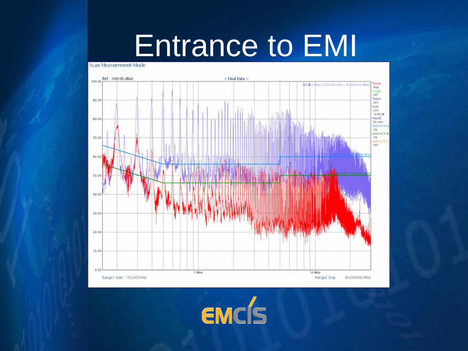
Entrance to EMI
What is EMC/EMI
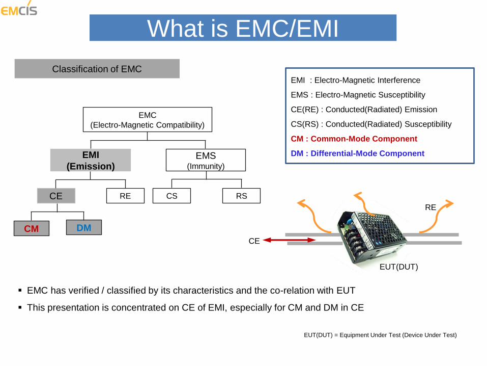
Classification of EMC EMI : Electro-Magnetic Interference
EMS : Electro-Magnetic Susceptibility
CE(RE) : Conducted(Radiated) Emission
CS(RS) : Conducted(Radiated) Susceptibility
CM : Common-Mode Component
DM : Differential-Mode Component
EMC
(Electro-Magnetic Compatibility)
EMI
(Emission) EMS
(Immunity)
CE RE
CM DM
CS RS
EMC has verified / classified by its characteristics and the co-relation with EUT
This presentation is concentrated on CE of EMI, especially for CM and DM in CE
CE
RE
EUT(DUT)
EUT(DUT) = Equipment Under Test (Device Under Test)
What is EMI
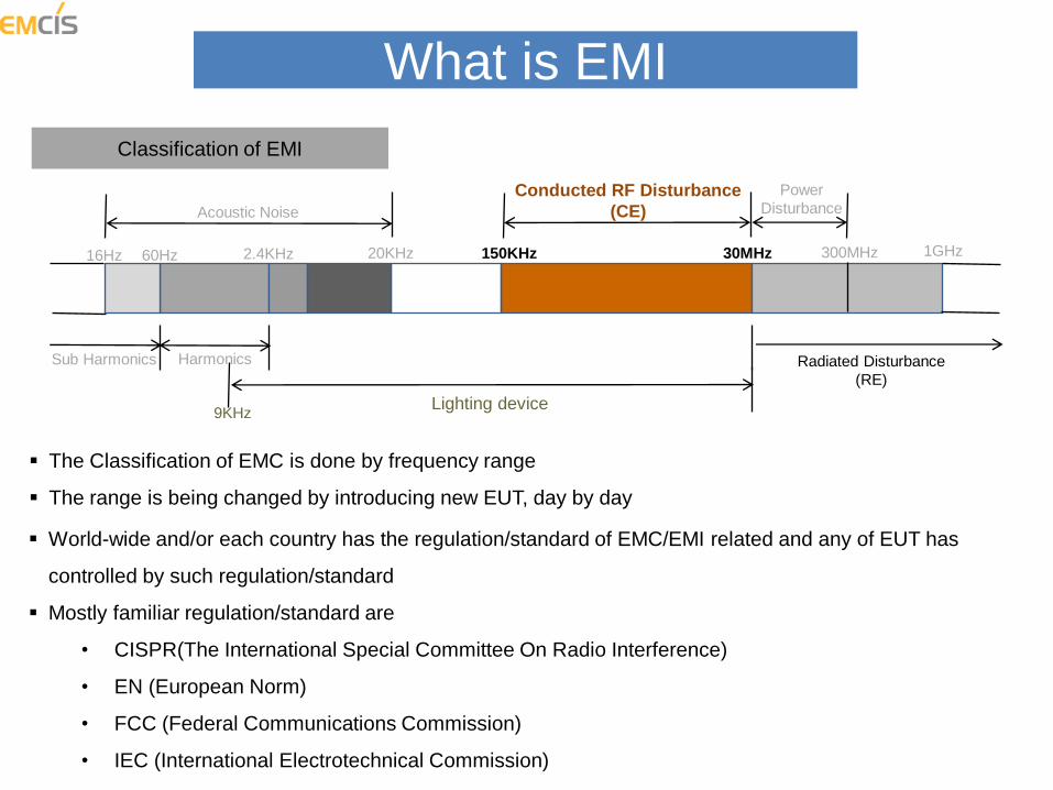
Classification of EMI
The Classification of EMC is done by frequency range
The range is being changed by introducing new EUT, day by day
16Hz 60Hz 2.4KHz 20KHz 150KHz 30MHz 300MHz 1GHz
Harmonics Sub Harmonics
Acoustic Noise
Conducted RF Disturbance
(CE)
Power
Disturbance
Radiated Disturbance
(RE)
9KHz Lighting device
World-wide and/or each country has the regulation/standard of EMC/EMI related and any of EUT has
controlled by such regulation/standard
Mostly familiar regulation/standard are
• CISPR(The International Special Committee On Radio Interference)
• EN (European Norm)
• FCC (Federal Communications Commission)
• IEC (International Electrotechnical Commission)
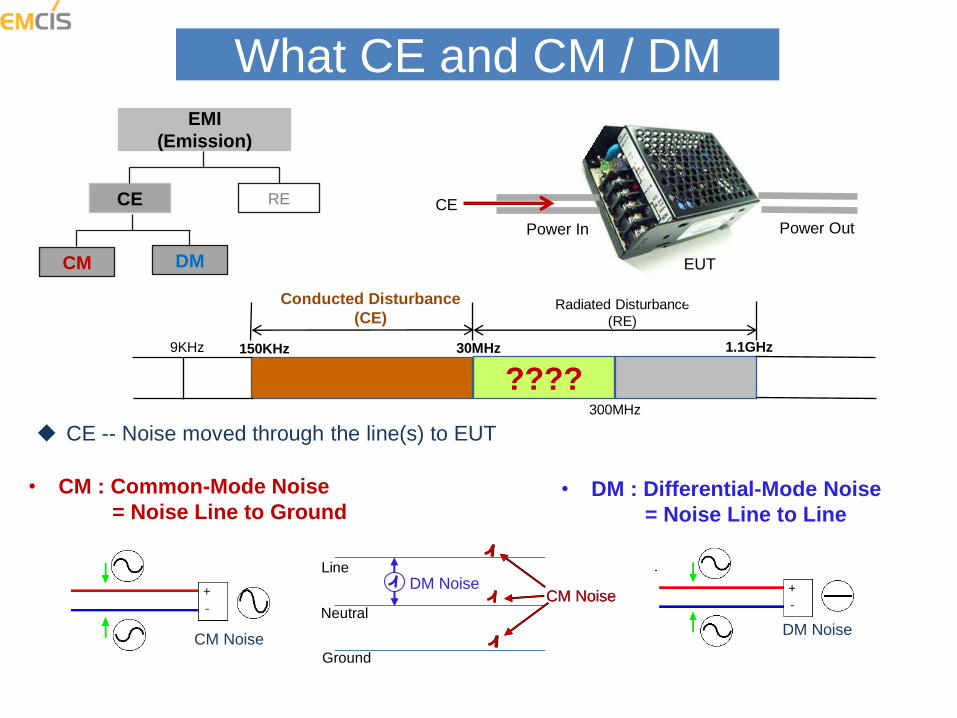
What CE and CM / DM EMI
(Emission)
CE RE
CM DM
CE -- Noise moved through the line(s) to EUT
9KHz 150KHz 30MHz 1.1GHz
Conducted Disturbance
(CE) Radiated Disturbance
(RE)
300MHz
????
CE
Power In Power Out
EUT
• CM : Common-Mode Noise
= Noise Line to Ground • DM : Differential-Mode Noise
= Noise Line to Line
CM Noise DM Noise
Ground
Neutral
Line
CM Noise DM Noise
CM Noise
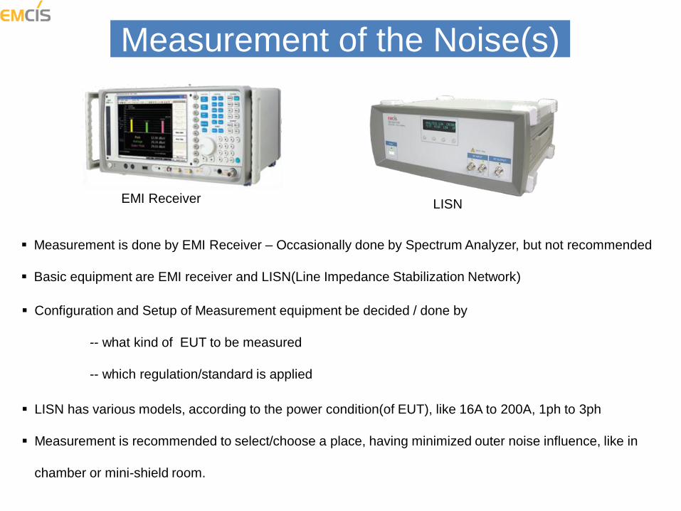
Measurement of the Noise(s)
LISN EMI Receiver
Configuration and Setup of Measurement equipment be decided / done by
-- what kind of EUT to be measured
-- which regulation/standard is applied
Measurement is done by EMI Receiver – Occasionally done by Spectrum Analyzer, but not recommended
Basic equipment are EMI receiver and LISN(Line Impedance Stabilization Network)
LISN has various models, according to the power condition(of EUT), like 16A to 200A, 1ph to 3ph
Measurement is recommended to select/choose a place, having minimized outer noise influence, like in
chamber or mini-shield room.

Measurement of the Noise(s)
LISN EMI Receiver EUT
Differential-Mode(DM)
Common-Mode(CM) Total Noise = CM + DM
Measured results
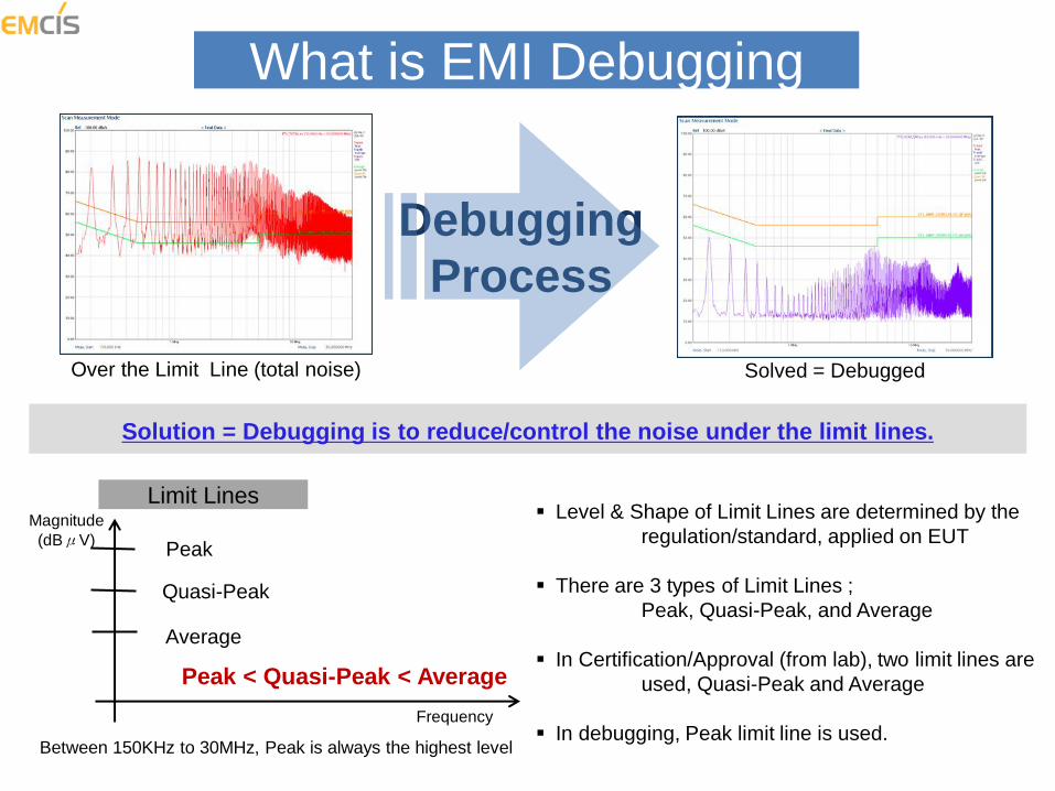
What is EMI Debugging
Over the Limit Line (total noise) Solved = Debugged
Debugging
Process
Solution = Debugging is to reduce/control the noise under the limit lines.
Level & Shape of Limit Lines are determined by the
regulation/standard, applied on EUT
There are 3 types of Limit Lines ;
Peak, Quasi-Peak, and Average
In Certification/Approval (from lab), two limit lines are
used, Quasi-Peak and Average
In debugging, Peak limit line is used.
Limit Lines
Peak
Quasi-Peak
Average
Peak < Quasi-Peak < Average
Frequency
Magnitude
(dBμV)
Between 150KHz to 30MHz, Peak is always the highest level
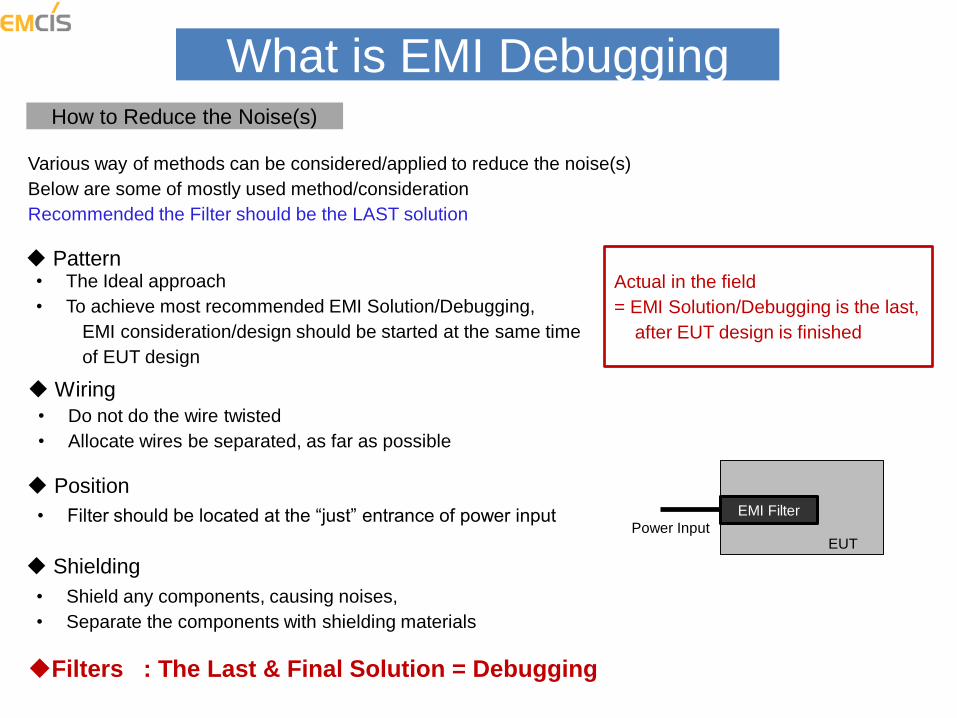
What is EMI Debugging How to Reduce the Noise(s)
Filters : The Last & Final Solution = Debugging
Pattern • The Ideal approach
• To achieve most recommended EMI Solution/Debugging,
EMI consideration/design should be started at the same time
of EUT design
Position
• Filter should be located at the “just” entrance of power input
Wiring
• Do not do the wire twisted
• Allocate wires be separated, as far as possible
Power Input
EMI Filter
EUT
Shielding
• Shield any components, causing noises,
• Separate the components with shielding materials
Various way of methods can be considered/applied to reduce the noise(s)
Below are some of mostly used method/consideration
Recommended the Filter should be the LAST solution
Actual in the field
= EMI Solution/Debugging is the last,
after EUT design is finished
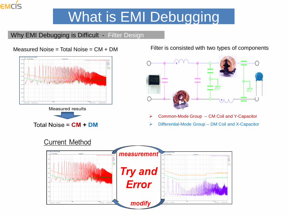
What is EMI Debugging Why EMI Debugging is Difficult - Filter Design
Measured Noise = Total Noise = CM + DM Filter is consisted with two types of components
Common-Mode Group -- CM Coil and Y-Capacitor
Differential-Mode Group -- DM Coil and X-Capacitor
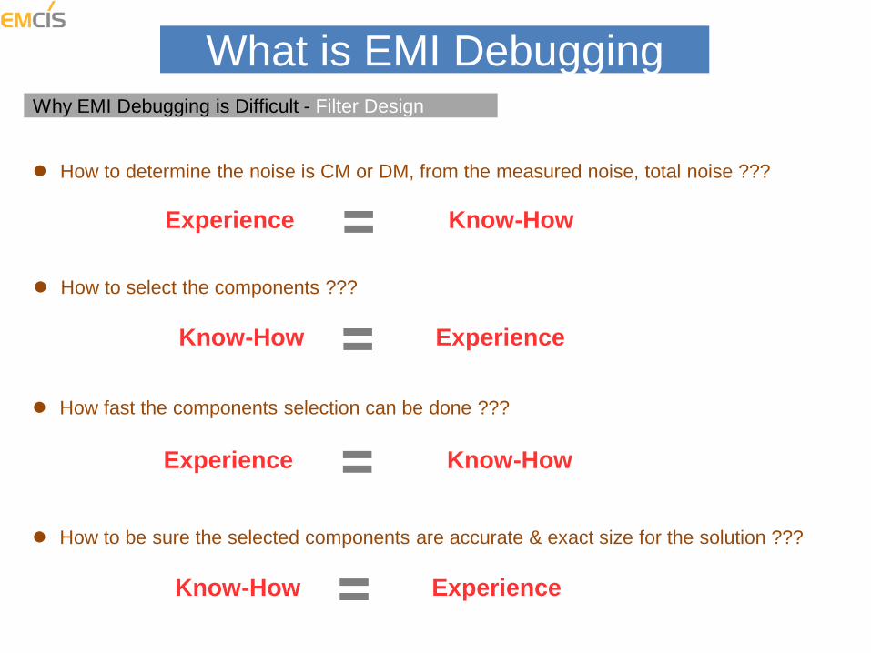
What is EMI Debugging Why EMI Debugging is Difficult - Filter Design
How to determine the noise is CM or DM, from the measured noise, total noise ???
How to be sure the selected components are accurate & exact size for the solution ???
How to select the components ???
How fast the components selection can be done ???
Experience Know-How
Experience Know-How
Experience Know-How
Experience Know-How

Summary of EMI Solution = Debugging = EMI Filter Design
• Analysis and Measurement of Exact Noise by mode, CM and DM
• EMI Solution = Debugging is finalized by EMI Filter (EMI Filter Design)
• Understanding more and more about the components being used on EMI Filter
• Design EMI Filter, using smaller Components and less Quantity
Successful EMI Debugging = Good & Fast Filter Design
COST SAVING = COMPETITIVENESS
What is EMI Debugging
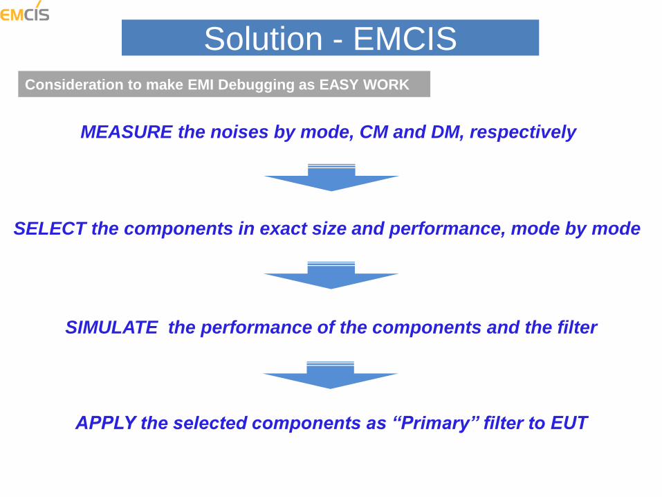
Solution - EMCIS
SELECT the components in exact size and performance, mode by mode
APPLY the selected components as “Primary” filter to EUT
SIMULATE the performance of the components and the filter
Consideration to make EMI Debugging as EASY WORK
MEASURE the noises by mode, CM and DM, respectively
Solution - EMCIS
Measure each of noises, CM and DM, respectively
Select Components per each Mode, CM and DM, one by one
Apply selected components as “Primary” filter to EUT
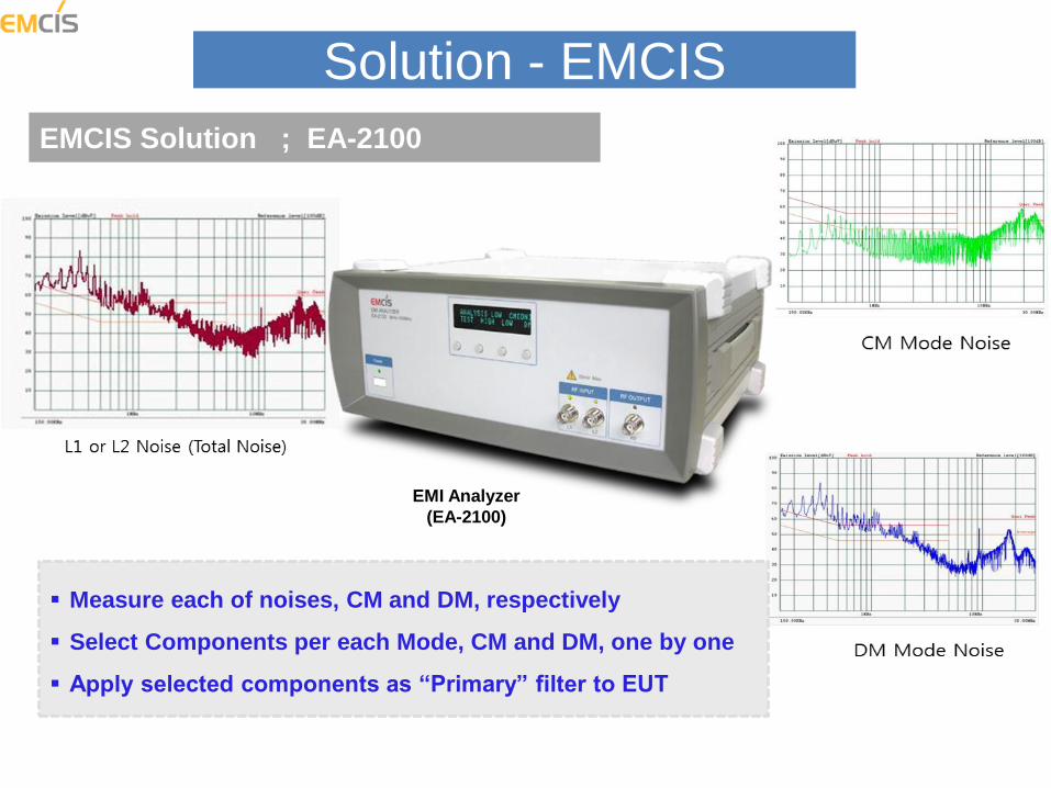
EMCIS Solution ; EA-2100
EMI Analyzer
(EA-2100)
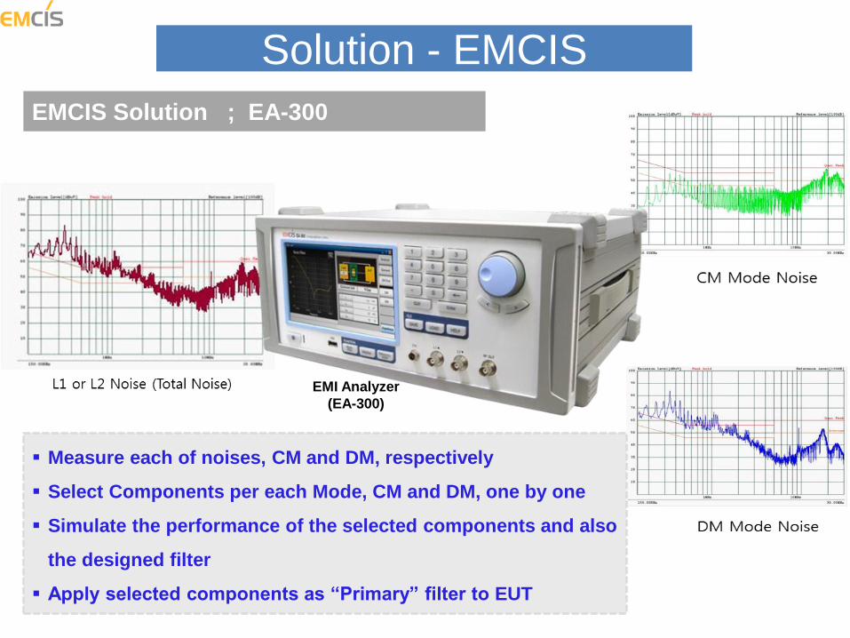
Solution - EMCIS
Measure each of noises, CM and DM, respectively
Select Components per each Mode, CM and DM, one by one
Simulate the performance of the selected components and also
the designed filter
Apply selected components as “Primary” filter to EUT
EMI Analyzer
(EA-300)
EMCIS Solution ; EA-300
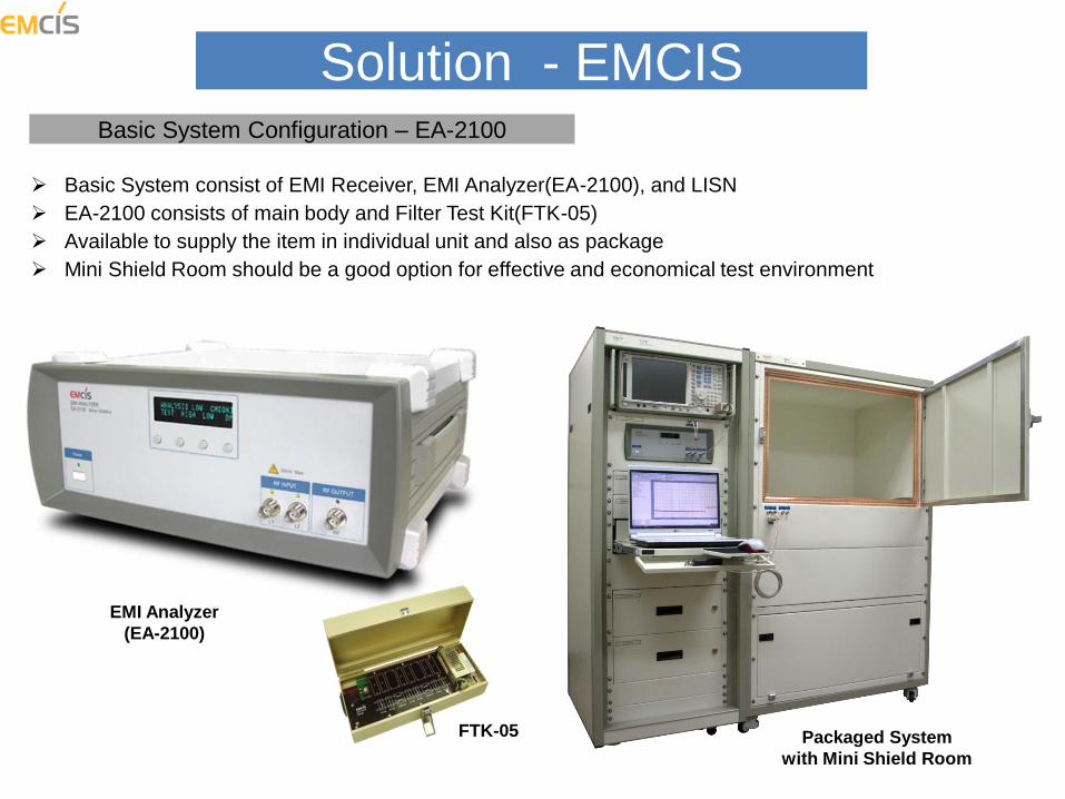
Solution - EMCIS Basic System Configuration – EA-2100
Basic System consist of EMI Receiver, EMI Analyzer(EA-2100), and LISN
EA-2100 consists of main body and Filter Test Kit(FTK-05)
Available to supply the item in individual unit and also as package
Mini Shield Room should be a good option for effective and economical test environment
FTK-05 Packaged System
with Mini Shield Room
EMI Analyzer
(EA-2100)
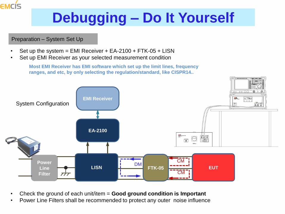
Debugging – Do It Yourself
Preparation – System Set Up
• Set up the system = EMI Receiver + EA-2100 + FTK-05 + LISN
• Set up EMI Receiver as your selected measurement condition
Most EMI Receiver has EMI software which set up the limit lines, frequency
ranges, and etc, by only selecting the regulation/standard, like CISPR14..
• Check the ground of each unit/item = Good ground condition is Important
• Power Line Filters shall be recommended to protect any outer noise influence
System Configuration EMI Receiver
EA-2100
Power
Line
Filter
LISN EUT
CM
CM
DM FTK-05
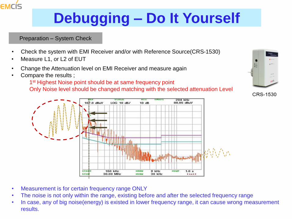
Debugging – Do It Yourself
Preparation – System Check
• Check the system with EMI Receiver and/or with Reference Source(CRS-1530)
• Measurement is for certain frequency range ONLY
• The noise is not only within the range, existing before and after the selected frequency range
• In case, any of big noise(energy) is existed in lower frequency range, it can cause wrong measurement
results.
1st Highest Noise point should be at same frequency point
Only Noise level should be changed matching with the selected attenuation Level
• Measure L1, or L2 of EUT
• Change the Attenuation level on EMI Receiver and measure again
• Compare the results ;
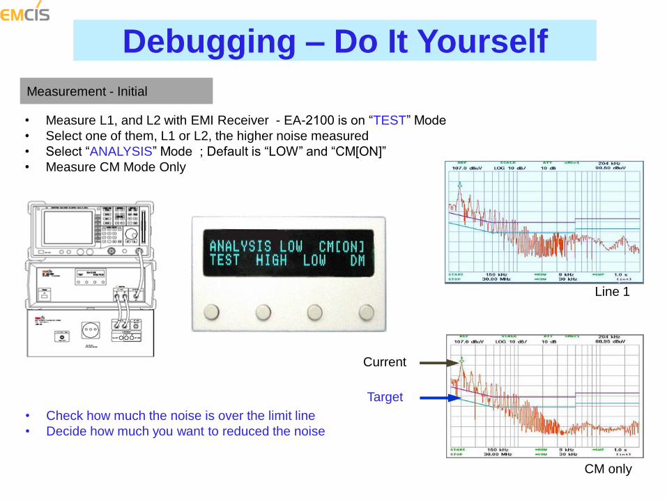
Debugging – Do It Yourself
Measurement - Initial
• Measure L1, and L2 with EMI Receiver - EA-2100 is on “TEST” Mode
• Select one of them, L1 or L2, the higher noise measured
• Select “ANALYSIS” Mode ; Default is “LOW” and “CM[ON]”
• Measure CM Mode Only
Line 1
CM only
• Check how much the noise is over the limit line
• Decide how much you want to reduced the noise
Current
Target
Debugging – Do It Yourself
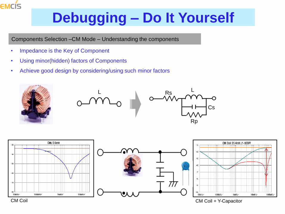
Components Selection –CM Mode – Understanding the components
• Impedance is the Key of Component
• Using minor(hidden) factors of Components
• Achieve good design by considering/using such minor factors
L Rs
Cs
Rp
L
CM Coil CM Coil + Y-Capacitor
Debugging – Do It Yourself
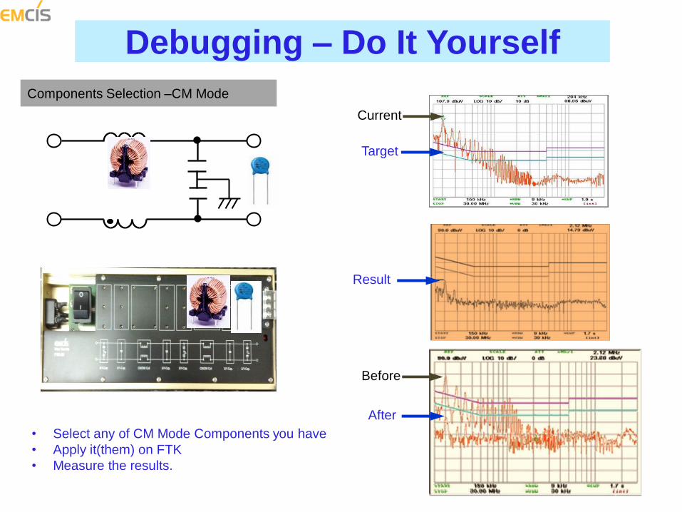
Components Selection –CM Mode
• Select any of CM Mode Components you have
• Apply it(them) on FTK
• Measure the results.
Current
Target
Result
Before
After
Debugging – Do It Yourself
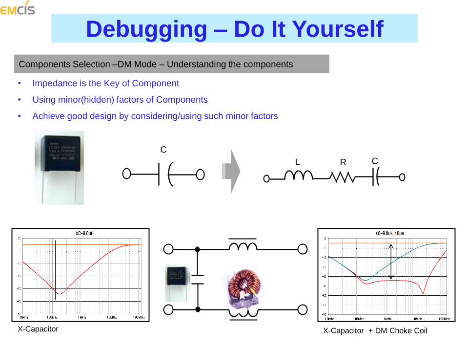
Components Selection –DM Mode – Understanding the components
• Impedance is the Key of Component
• Using minor(hidden) factors of Components
• Achieve good design by considering/using such minor factors
X-Capacitor
C
L R C
X-Capacitor + DM Choke Coil
Debugging – Do It Yourself
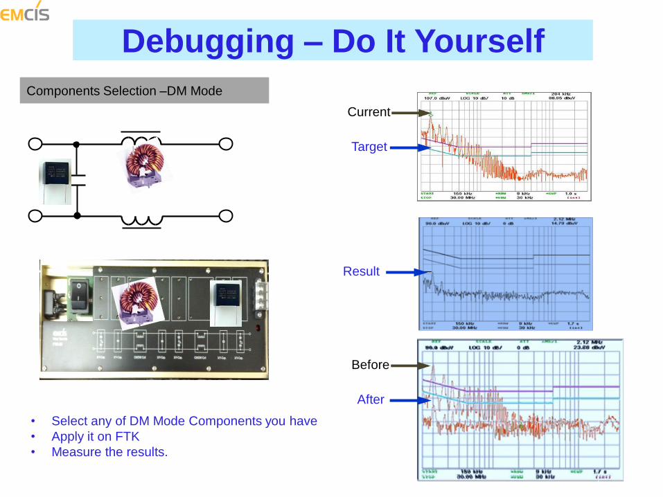
Components Selection –DM Mode
• Select any of DM Mode Components you have
• Apply it on FTK
• Measure the results.
Current
Target
Result
Before
After
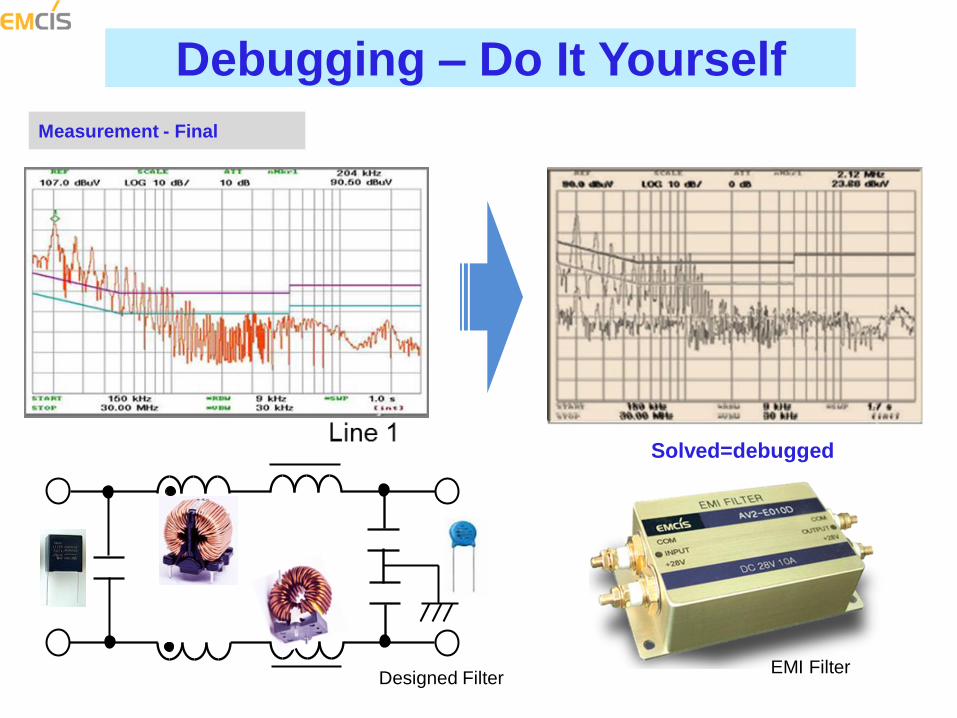
Debugging – Do It Yourself
Measurement - Final
Solved=debugged
Designed Filter EMI Filter
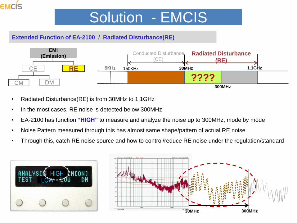
Extended Function of EA-2100 / Radiated Disturbance(RE)
Solution - EMCIS
EMI
(Emission)
CE RE
CM DM
9KHz 150KHz 30MHz 1.1GHz
Conducted Disturbance
(CE) Radiated Disturbance
(RE)
300MHz
????
• Radiated Disturbance(RE) is from 30MHz to 1.1GHz
• In the most cases, RE noise is detected below 300MHz
• EA-2100 has function “HIGH” to measure and analyze the noise up to 300MHz, mode by mode
• Noise Pattern measured through this has almost same shape/pattern of actual RE noise
• Through this, catch RE noise source and how to control/reduce RE noise under the regulation/standard
HIGH LOW
30MHz 300MHz


