Embed Size (px)
Citation preview

EnterpriseOne JDE5Development Tools PeopleBook
May 2002


EnterpriseOne JDE5 Development Tools PeopleBook SKU JDE5EOD0502 Copyright© 2003 PeopleSoft, Inc. All rights reserved. All material contained in this documentation is proprietary and confidential to PeopleSoft, Inc. ("PeopleSoft"), protected by copyright laws and subject to the nondisclosure provisions of the applicable PeopleSoft agreement. No part of this documentation may be reproduced, stored in a retrieval system, or transmitted in any form or by any means, including, but not limited to, electronic, graphic, mechanical, photocopying, recording, or otherwise without the prior written permission of PeopleSoft. This documentation is subject to change without notice, and PeopleSoft does not warrant that the material contained in this documentation is free of errors. Any errors found in this document should be reported to PeopleSoft in writing. The copyrighted software that accompanies this document is licensed for use only in strict accordance with the applicable license agreement which should be read carefully as it governs the terms of use of the software and this document, including the disclosure thereof. PeopleSoft, PeopleTools, PS/nVision, PeopleCode, PeopleBooks, PeopleTalk, and Vantive are registered trademarks, and Pure Internet Architecture, Intelligent Context Manager, and The Real-Time Enterprise are trademarks of PeopleSoft, Inc. All other company and product names may be trademarks of their respective owners. The information contained herein is subject to change without notice. Open Source Disclosure This product includes software developed by the Apache Software Foundation (http://www.apache.org/). Copyright (c) 1999-2000 The Apache Software Foundation. All rights reserved. THIS SOFTWARE IS PROVIDED “AS IS’’ AND ANY EXPRESSED OR IMPLIED WARRANTIES, INCLUDING, BUT NOT LIMITED TO, THE IMPLIED WARRANTIES OF MERCHANTABILITY AND FITNESS FOR A PARTICULAR PURPOSE ARE DISCLAIMED. IN NO EVENT SHALL THE APACHE SOFTWARE FOUNDATION OR ITS CONTRIBUTORS BE LIABLE FOR ANY DIRECT, INDIRECT, INCIDENTAL, SPECIAL, EXEMPLARY, OR CONSEQUENTIAL DAMAGES (INCLUDING, BUT NOT LIMITED TO, PROCUREMENT OF SUBSTITUTE GOODS OR SERVICES; LOSS OF USE, DATA, OR PROFITS; OR BUSINESS INTERRUPTION) HOWEVER CAUSED AND ON ANY THEORY OF LIABILITY, WHETHER IN CONTRACT, STRICT LIABILITY, OR TORT (INCLUDING NEGLIGENCE OR OTHERWISE) ARISING IN ANY WAY OUT OF THE USE OF THIS SOFTWARE, EVEN IF ADVISED OF THE POSSIBILITY OF SUCH DAMAGE. PeopleSoft takes no responsibility for its use or distribution of any open source or shareware software or documentation and disclaims any and all liability or damages resulting from use of said software or documentation.


Table of Contents
OneWorld Development Tools Overview 1 OneWorld Tools ..............................................................................................1
OneWorld Acronyms................................................................................................ 2 Understanding Objects and Applications................................................................. 3 Understanding How to Build an Application ............................................................ 4
Fundamentals 11 Object Management Workbench.....................................................................11
Working with the Object Management Workbench ................................................. 14 Working with Projects .............................................................................................. 16 Working with Tokens ............................................................................................... 34 Working with Attachments ....................................................................................... 39
Data Dictionary................................................................................................41 Using the Data Dictionary........................................................................................ 44 Defining a Data Item................................................................................................ 45 Data Dictionary Naming Conventions...................................................................... 47 Data Dictionary Naming Conventions...................................................................... 60
Table Design ...................................................................................................74 Adding a Table......................................................................................................... 75 Table Naming Conventions ..................................................................................... 77 Working with Table Design...................................................................................... 78 Working with Tables ................................................................................................ 82 Viewing the Data in Tables...................................................................................... 84
Business View Design.....................................................................................88 Table Join ................................................................................................................ 88 Table Union ............................................................................................................. 90 Select Distinct .......................................................................................................... 91 Indices ..................................................................................................................... 91 Adding a Business View .......................................................................................... 91 Working with Business View Design ....................................................................... 93
Data Structures ...............................................................................................103 System-Generated Data Structures ........................................................................ 103 User Generated Data Structures ............................................................................. 104 Working with Interconnection Data Structures ........................................................ 104 Creating a Data Structure........................................................................................ 107 Defining a Data Structure ........................................................................................ 112 Creating a Type Definition ....................................................................................... 113
Cross Reference Facility .................................................................................114
Application Design 127 Understanding Applications..................................................................................... 127 Adding an Interactive Application ............................................................................ 128
Forms Design ..................................................................................................131 What is a Form? ...................................................................................................... 131 Elements of a Form ................................................................................................. 132 Understanding Form Types ..................................................................................... 133
Creating a Form....................................................................................................... 143 Designing a Form Layout ........................................................................................ 147 Working with Menu/Toolbar Exits ............................................................................ 153 Working with Controls.............................................................................................. 159 Overriding Data Dictionary Triggers at Design Time............................................... 205 Using Text Variables................................................................................................ 211 Using Quick Form.................................................................................................... 215 Testing a Form......................................................................................................... 225
Event Rules 227 Event Rules Design.........................................................................................227
Understanding Controls........................................................................................... 227 Understanding Events ............................................................................................. 227 Understanding Form Processing ............................................................................. 228 Understanding Event Rules..................................................................................... 228 Understanding the Event Rule Buttons ................................................................... 229 Event Rules Based on Form Type........................................................................... 230 Runtime Processing................................................................................................. 230 Working with Event Rules Design ........................................................................... 249 Working with If and While Statements..................................................................... 259 Working with Event Rule Variables ......................................................................... 264 Creating Form Interconnections .............................................................................. 280 Creating Report Interconnections............................................................................ 286 Creating Assignments.............................................................................................. 290 Table I/O .................................................................................................................. 297 Table Event Rules ................................................................................................... 307 Creating Dynamic Overrides ................................................................................... 310 Working with Asynchronous Processing ................................................................. 311 BrowsER.................................................................................................................. 315 Using Visual ER Compare....................................................................................... 320
Business Functions 324 What are the Components of a Business Function? ............................................... 324 How Distributed Business Functions Work ............................................................. 326 Creating Business Function Event Rules ................................................................ 327 Understanding Header File Sections....................................................................... 331 Understanding the Structure of a Business Function Source File........................... 336 Using Application Programming Interfaces (APIs) .................................................. 340 Working with Business Functions............................................................................ 348 Creating and Specifying Custom DLLs.................................................................... 350 Working with Business Function Builder ................................................................. 352 Transaction Master Business Functions.................................................................. 365 Master File Master Business Functions................................................................... 378 Business Function Documentation .......................................................................... 382 Understanding Business Function Processing Failovers ........................................ 393
Caching 395 Understanding JDECACHE..................................................................................... 395 Working with JDECACHE........................................................................................ 397 JDECACHE Cursors................................................................................................ 404 JDECACHE Errors................................................................................................... 410 JDECACHE Example Program ............................................................................... 410 JDECACHE Standards............................................................................................ 422
Additional Features 427 Processing Options .........................................................................................427
Processing Options Templates................................................................................ 427 Defining a Processing Options Data Structure (Template) ..................................... 428 Attaching a Processing Options Template .............................................................. 436
Transaction Processing...................................................................................437 Commits and Rollbacks........................................................................................... 437 Understanding Transaction Processing................................................................... 438 Working with Transaction Processing ..................................................................... 441 Setting the jde.ini for Transaction Processing and Lock Manager .......................... 452
Record Locking ...............................................................................................460 Understanding Record Locking ............................................................................... 460
Currency..........................................................................................................461 OneWorld Currency Implementation ....................................................................... 462 Advantages.............................................................................................................. 462 Working with Currency............................................................................................. 462
Menu Design ...................................................................................................470 Understanding Menus.............................................................................................. 470 Working with Menus ................................................................................................ 471 Working with Menu Selections ................................................................................ 475 Working with Menu Selection Revisions.................................................................. 485
Tips of the Day ................................................................................................489 Working with Tips of the Day................................................................................... 489
Messaging 494 Message Types ....................................................................................................... 494 Understanding Error Handling ................................................................................. 495 Working with Error Messages.................................................................................. 502 Working with the Send Message System Function ................................................. 513
Batch Error Messages.....................................................................................523 Understanding Batch Error Messaging.................................................................... 523 Creating a Level-Break Message ............................................................................ 528
Debugging 543 Overview of the Debugging Process ....................................................................... 543 Interpretive and Compiled Code.............................................................................. 544 Working with the Event Rules Debugger................................................................. 544 Debugging Business Functions Using Microsoft Visual C++ .................................. 550 Working with the Visual C++ Debugger................................................................... 554 Debugging Strategies .............................................................................................. 556 Debug Tracing ......................................................................................................... 560
Web Applications 563 Developing Web Applications..........................................................................563
Understanding the HTML Client .............................................................................. 566 Generating Web Applications .................................................................................. 567
Performance 574 Performance Tips .................................................................................................... 574
Additional Information for OneWorld Development Tools 585 OneWorld Modification Rules..........................................................................585
What an Upgrade Preserves and Replaces ............................................................ 586 Form Processing .............................................................................................595
Process Flow for Find/Browse Form ....................................................................... 596 Process Flow for Parent/Child Browse Form .......................................................... 599 Process Flow for Fix/Inspect Form.......................................................................... 603 Process Flow for Header Detail Form ..................................................................... 606 Process Flow for Headerless Detail Form............................................................... 612 Process Flow for Search/Select Form..................................................................... 617 Process Flow for Message Form............................................................................. 620 Process Flow for Edit Control .................................................................................. 620 Process Flow for Grid Control ................................................................................. 622
Date Reference Scan ......................................................................................627 Working with the Date Reference Scan................................................................... 627

OneWorld Development Tools Overview
OneWorld Tools
The OneWorld Tools are an integrated set of application development tools. These tools allow business analysts to develop complete interactive and batch applications, such as forms and reports. The tools simplify the development process and limit the amount of programming necessary to create applications.
OneWorld Tools also allow you to create applications for client/server environments using the stability of J.D. Edwards methodology and the ease of the Microsoft Windows interface.
Fundamentals Fundamentals covers the basic concepts and tools you need to know to start developing applications. It includes the preliminary steps you must take before you actually design an application. Fundamentals includes the following:
• Object Management Workbench
• Data Dictionary
• Table Design
• Business View Design
• Data Structures
• Cross Reference
• Checkout Log
Application Design Application Design includes the steps that you follow to actually design an application. It describes different form types and controls.
Event Rules Event Rules discusses using event rules and logic. It also describes how to use BrowsER.
Business Functions Business Functions discusses both C business functions and named event rules. It also has information about master business functions, Business Function Builder, and business function documentation.
Caching Caching describes how you can use caching for better performance.
Additional Features Additional Features discusses additional features of the OneWorld development tools that you can use to enhance your applications. It includes the following:
• Processing options
• Transaction processing
• Record locking
1

• Currency
• Menu design
Messaging Messaging discusses error handling, interactive messaging, and batch messaging.
Debugging Debugging provides information to help you debug your applications. It includes different methods of debugging and strategies to help you.
Web Applications Web Applications discusses designing and generating Web applications.
Performance Performance discusses troubleshooting your application and addressing various performance issues. It includes tips to help you develop better-performing applications.
Appendices The appendices include information about software modifications and detailed information about the process flow for different form types. The appendices include:
• OneWorld modification rules
• Form processing
• Date reference scan
OneWorld Acronyms
Following are some acronyms that are commonly used in OneWorld.
APPL Application
BDA Business View Design Aid
BSFN Business Function
BSVW Business View
CRP Conference Room Pilot
DD Data Dictionary
DLL Dynamic Link Library
DS or DSTR Data Structure
ER Event Rules
FDA Form Design Aid
NER Named Event Rules
2
OCM Object Configuration Manager
OL Object Librarian
OMW Object Management Workbench
QBE Query by Example
RDA Report Design Aid
SAR Software Action Request
Specs Specifications
TAM Table Access Management
TBLE Table
TC Table Conversion
TDA Table Design Aid
TER Table Event Rules
UBE Universal Batch Engine
UTB Universal Table Browser
WF Workflow
Understanding Objects and Applications
J.D. Edwards uses OneWorld Tools to build objects, which are used to build applications.
Understanding an Object
By industry standards, an object is a self-sufficient entity that contains data as well as the structures and functions used to manipulate that data. In OneWorld, an object is a reusable entity that is based on software specifications created by the OneWorld Tools.
A specification is a complete description of a OneWorld object. Each object has its own specification, which is stored on both the server and the workstation. Some specifications describe different types of objects. For example, the data structure specification is used to describe a business function data structure, a processing option structure, and a media object structure.
The OneWorld architecture is object-based. This means that discrete software objects are the basis for all applications, and that developers can reuse the objects in multiple applications. This use of objects (applications being broken down into smaller components) allows J.D. Edwards to provide true distributed processing. Developers create the objects using OneWorld Tools.
3

Examples of OneWorld objects include the following:
• Batch applications
• Business functions (encapsulated routines)
• Business views
• Data dictionary items
• Data structures
• Event rules
• Interactive applications
• Media objects
• Tables
Understanding an Application
An application is a collection of objects that performs a specific task. J.D. Edwards uses the OneWorld Tools to build the following standard groups of related applications:
• Architecture, engineering, and construction
• Distribution
• Energy and chemical systems
• Financial
• Workforce management
• Manufacturing
• Technical
These applications share a common user interface because they are all generated through OneWorld Tools. Applications refer to both interactive and batch applications. For example, all of the following are applications:
• Address Book Revisions
• Sales Order Entry
• General Ledger Post
• Trial Balance Report
Understanding How to Build an Application
You can use the OneWorld Tools to build your applications.
You might not need to use every tool to create an application; however, you always begin your application development from the Object Management Workbench. For example, you might not need to add or modify data items. If so, you can proceed to Table Design from the Object Management Workbench. If one or more existing database tables already contain all of the data items that you want to include in your application, then you can skip the step of designing a table and proceed to Business View Design.
4

Understanding the Development Cycle
The following figure illustrates the software development cycle, showing relationships between the tools.
5
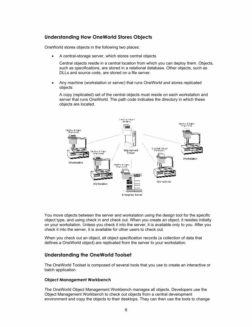
Understanding How OneWorld Stores Objects
OneWorld stores objects in the following two places:
• A central-storage server, which stores central objects
Central objects reside in a central location from which you can deploy them. Objects, such as specifications, are stored in a relational database. Other objects, such as DLLs and source code, are stored on a file server.
• Any machine (workstation or server) that runs OneWorld and stores replicated objects
A copy (replicated) set of the central objects must reside on each workstation and server that runs OneWorld. The path code indicates the directory in which these objects are located.
You move objects between the server and workstation using the design tool for the specific object type, and using check in and check out. When you create an object, it resides initially on your workstation. Unless you check it into the server, it is available only to you. After you check it into the server, it is available for other users to check out.
When you check out an object, all object specification records (a collection of data that defines a OneWorld object) are replicated from the server to your workstation.
Understanding the OneWorld Toolset
The OneWorld Toolset is composed of several tools that you use to create an interactive or batch application.
Object Management Workbench
The OneWorld Object Management Workbench manages all objects. Developers use the Object Management Workbench to check out objects from a central development environment and copy the objects to their desktops. They can then use the tools to change
6

objects and check in the objects so that others can access the objects. Developers can access only OneWorld Tools through the Object Management Workbench.
Data Dictionary
Just as a dictionary contains word definitions, the J.D. Edwards data dictionary is a central repository that contains data item definitions and attributes. These attributes determine the way in which a data item does the following:
• Appears on reports and forms (such as number of decimals and default values)
• Validates data entry within an application
• Assigns column and row descriptions
• Provides text for field-sensitive help
• Is stored in a table
The data dictionary is active because the changes that you enter in it are automatically reflected in applications; you do not need to recompile the software to see the changes.
Table Design
A relational database table stores data that an application uses. You can create one or more tables for use in an application. To create a table, select data items for the table and assign key fields as indices for retrieving and updating data.
Table Design Aid creates a .H file. You use OMW to check this file into source.
Business View Design
Business views are the link between applications and data. A business view defines the data items from one or more tables that an application uses. After you create the tables, select the data items from one or more tables that you want to include in your business view. With business views, you can select only the columns that you need in the application, which increases performance by reducing the amount of data that must move over the network. For example, from a table that contains all employee data, you can create a business view that contains only employee names and addresses.
Form Design
An interactive application allows a user to access a database (based on a business view). A user accesses an interactive application to add, modify, or view data using a form.
To create an application, determine the type of form that your application requires, and associate each form with a business view. To design forms, you add controls such as a grid, edit fields, push buttons, and radio buttons.
7

Several standard form types have much of the required processing already established. Examples include:
Find/Browse Used for inquiry forms, such as Work with Sales Orders.
Fix/Inspect Used to add or modify a single record. Sales Order Header is an example of a Fix/Inspect form.
Header Detail Used to modify multiple records at a time (particularly on normalized tables). Sales Order Detail is an example of a Header Detail form.
Headerless Detail
Used to modify multiple records in a table that is not normalized. Voucher Entry is an example of a Headerless Detail form.
Search and Select
Used to automatically retrieve data in a visual assist field.
Parent/Child Used to display multiple records that have a parent/child relationship in an Explorer-like tree view. Bill of Material is an example of a Parent/Child form.
Message Used to display messages or request action. Delete Confirmation is an example of a Message form.
Report Design
You use Report Design to create reports and batch processes. In Report Design, you design sections instead of forms. To create a report, determine the data that you want to appear on the report. Attach event rules that provide business logic, and specify processing options that control the format, page breaks, report totaling, and how the report processes data. Examples of reports and batch processes are:
• Sales Update
• General Ledger Post
• Trial Balance by Cost Center
• Invoices
• Table Conversions
• Financial Reporting
Business Function Design
A business function is an encapsulated reusable routine that can be called through event rules. This code can be written in most industry standard third-generation languages. You use Business Function Design to write business functions to provide background processing to handle specialized tasks that an application needs, such as specialized editing on a field.
Event Rules
Event rules are logic statements. You create event rules and attach them to events. Events are activities that occur in an application, such as entering a form, exiting a field, exiting a row, or initiating a page break on a report. Event rules process when the user or the system initiates an event. Events are attached to controls, such as a particular field, the entire form, the grid, or a report section.
8
You use event rules to create complex business logic without the difficult syntax that comes with most programming languages. Examples of business logic that you can accomplish with event rules include:
• Perform a mathematical calculation
• Perform table I/O (fetch, insert, delete)
• Pass data from a source field on a form to a target field on another form
• Connect two forms or applications
• Hide or display a control using a system function
• Evaluate If/While and Else conditions
• Assign a value to an expression in a field
• Create variables (work fields) as you are working
• Perform a batch process after completing an interactive application
• Attach a business function or system function
• Initiate workflow processes
The two types of Event Rules are:
• Business function event rules
• Embedded event rules
Business Function Event Rules Business function event rules are encapsulated, reusable business logic created through event rules, rather than C programming. They are stored as objects and are compiled.
Embedded Event Rules Embedded event rules are specific to a particular table, interactive application, or batch application. They are not reuseable. Examples include creating form-to-form calls, hiding a field based on a processing options value, and calling a business function. You can have embedded event rules in application event rules (interactive or batch) or in table event rules.
Application event rules (interactive or batch)
Allow you to add business logic that is specific to a particular application. Interactive applications connect event rules using the Form Design Aid, while batch event rules use Report Design.
Table event rules Allow you to create OneWorld database triggers, or rules that are attached to a table and are executed through Table Design Event Rules. The logic attached to a table is executed whenever any application initiates that database action. For example, to maintain referential integrity, you might have rules on a master table that delete all children when a parent is deleted. Any application that initiates a delete of that table does not need to include the parent/child logic because that logic exists resides at the table level.
9

Processing Options
Processing options control how interactive and batch applications process data. You can have several versions of the same basic set of processing options. Each version might have one slight difference from another version. For example, you can use processing options to do the following:
• Determine the sequence of the forms in an application
• Set default values
• Turn on and off special processing, such as currency or kit processing in Sales Order Entry
Menus
Menus are the entry point to J.D. Edwards applications and reports. To access an application or report from a menu, it must be attached to a menu selection, and menu selections must be attached to a menu. See the OneWorld Foundation guide for information about creating customized menus.
10

Fundamentals
Object Management Workbench
The Object Management Workbench (OMW) is the change management system for OneWorld development. A change management system is vital to a productive development environment because it helps organize a myriad of development activities and helps prevent problems, such as when a developer intermixes components from different releases or when multiple developers simultaneously change an object. OMW automates many of these change management activities.
The three OMW systems are:
Graphical User Interface (GUI) Unifies all development in an intuitive interface
Configuration System Controls all development from a central location
Logging System Automatically tracks all program changes
This unit discusses the OMW GUI. The configuration and logging systems are discussed in Object Management Workbench Configuration in the OneWorld System Administration guide.
See Also Configuring Notification Subscriptions in the System Administration documentation
for information about using the OMW to notify you when specific events occur
Projects
Projects are composed of objects and owners. All development of objects within OneWorld must be performed within the context of a project. Usually, you must first create or choose a project, add an object to it, and then you can work with that object. Typically, objects are included in a project because they have been modified or created by a developer to complete a specific task.
In addition to objects, users can be associated with different projects. In fact, before you can add an object to a project, you must have been added to the project as a user in a role that has permission to add objects. A user can be assigned to the same project more than once with different roles. Projects may also contain other projects.
Default Project
The default project is your personal project that can be used for development and research. It holds any miscellaneous development objects that you want to work with but that you have not associated with a specific project. OneWorld creates a default project when you run the OMW for the first time. OneWorld uses your OneWorld logon to name the default project.
Use your default project to do the following:
• Research, develop, and prototype objects
• Review objects that you do not need to modify or check in
The default project is similar to other projects; however, the status of a default project does not change. Therefore, you cannot use a default project to transfer objects.
11

Some objects, such as versions, menus, workflow data, and reports can be created and edited outside of the OMW. Nevertheless, any changes that you make to these objects must be tracked and managed. You use your default project to manage these objects. If you create or access such objects outside of the OMW, these objects are added to your default project.
User Roles
Users must be assigned to a project before they can affect the project or the objects within that project. When you add a user to a project, you also identify the role of the user within the project. The user role defines the function of the user within the project organization and might limit the user's access to certain OMW functions, depending on the allowed actions associated with the role. User roles and their allowed actions are defined in the Object Management Configuration application.
Note Do not confuse user roles in the OMW with the concept of user roles as applied in other components of OneWorld software, such as the ActivEra Solution Explorer. OMW roles function independently of all other role-based systems in OneWorld.
Allowed Actions
Allowed actions are rules that define the actions that may be performed by a user who is assigned to a user role at a given project status. An administrator uses the OMW configuration application to set up these rules for each user role, object type, and project status.
Tokens
Some objects use tokens to minimize the possibility of one user overwriting another user's changes to an object. Projects hold tokens for an object, and each object has only one token. You can check out an object only if your project holds the token for the object. In this way, an object can reside in several projects, but can be checked out and in only by qualified users of the project that holds the token. You can, however, allow other projects to share an object's token, thereby allowing the object to be checked out and in by qualified users of one or more projects. However, only one person can check out an object at a time.
Note Only Object Librarian objects have tokens. See Object Librarian and Non-Object Librarian Objects for more information about Object Librarian objects.
12

Object Management Workbench Interface
From left to right, the initial OMW form displays the following:
• The project window, which displays your projects and their related objects and users. To view your current projects, click Find.
The following information describes how the color of an Object Librarian Object icon indicates its status:
• Gray Object Icon with Checkmark: Another project holds the token for this object.
• Colored Object Icon (not gray): The project that contains the object holds the token for this object.
• Colored Object Icon with Checkmark (not gray): The project that contains the object holds the token for the object, and the object is checked out.
• Gray Object Icon: This object is not checked out and no project currently holds the object for the token.
Non-Object Librarian Object icons do not vary in appearance.
Objects to be deleted are marked in bold in this window.
• The center column, which contains action buttons that you use to perform actions on a selected object. Available buttons vary based on your roles in the current project and on the status of the project in which the selected object resides. When you first launch the OMW, no buttons appear in the center column because you have not selected an object.
13

• The information window, which displays a web site; project status and release information; object or user information; and search results. Initially, the window displays a web site or HTML page. The contents change based on your tab and object selections. For example, when you select a project or an object in the project window, the information window displays information about the selected project or object. To return this window to its initial state, click News.
Object Librarian and Non-Object Librarian Objects
The OMW provides control of OneWorld objects in a simple, integrated, graphical user interface for OneWorld development. In OneWorld, an object is a reusable entity based on software specifications that are created by OneWorld Tools. OneWorld objects include Object Librarian objects such as interactive applications (APPL), batch applications (UBE), and data structure (DSTR) objects.
The OMW also allows control of some non-Object Librarian objects that are based on data source rather than path code.
OneWorld objects include the following Object Librarian objects:
• Batch applications and versions (UBE)
• Business functions (BSFN)
• Business views (BSVW)
• Data structures (DSTR)
• Interactive applications (APPL)
• Media objects (GT)
• Tables (TBLE)
OneWorld objects include the following non-Object Librarian objects:
• Data dictionary items
• User defined code items
• Workflow items
• Menus
Working with the Object Management Workbench
After your system administrator has configured the Object Management Workbench (OMW), including setting up security and roles, you can start working with the OMW. This topic suggests the order of actions to take to accomplish certain tasks with the OMW.
To Use Your Default Project
Although your default project appears immediately, you have one role only, as configured by your system administrator (usually Originator). You might need to add yourself to your default project in another role, such as Developer. See Adding Users to Projects for instructions for adding yourself in additional roles to a project.
14

Understanding Project Life Cycle
This topic discusses a typical project life cycle from inception to completion. It includes steps required by a SAR-based system. If you are not using a SAR-based system, some of the following steps might not apply to you. Furthermore, depending on your business's software development procedures, the steps that you follow and their order might vary from the following process.
1. Based on the task to be accomplished, create a new project.
See Creating New Projects for instructions for creating a new project.
2. Add users to the project.
When you add a user, you define the role of the user, based on the actions that you want that user to be able to perform within this project. You might need to add a user more than once if you want the user to be able to perform actions allowed by different roles. As the project progresses, you can continue to add (or remove) users as required.
When you create a project with SAR integration turned off, you are automatically added to that project in the role determined by your system administrator (usually, as the Originator). You might want to add yourself to the project in other roles as well.
When you create a project with SAR integration turned on, the person who entered the SAR is added to the project in the role of Originator.
See Adding Users to Projects for instructions for adding users to a project.
3. Add objects to the project.
Qualified users might be adding objects to the project throughout much of its life cycle.
If you create a new object, drag and drop the object from your default project to the project, when appropriate.
See Adding Objects to Projects for instructions for getting existing objects. Note that getting an object is not the same as checking out an object.
4. Check objects out and in.
To be able to save your changes to an object, you must check the object out, apply your changes, and check in the object. See Checking Objects In and Out for instructions for checking objects in and out.
When you attempt to check out an object, you will be successful if no other projects hold the token for that object. If the token is available, it passes to your project when you check the object out. If another project already holds the token for the object, you can join a token queue to be notified when the token becomes available. See Working with Tokens for information about how tokens work.
After checking out an object and modifying it, you can save your changes without checking the object in. See Changing Objects for instructions for saving objects.
When you check an object in, the system might not release the token from the project, depending on how the OMW has been configured. As long as your project holds the token, another qualified user in your project can check the object out, but users in other projects cannot. You can allow users in other projects to check out an
15
object by removing the object from the project (see Removing Objects from Projects), by releasing the token (see Releasing Tokens Manually), by switching the token (see Switching Tokens), or by sharing the token with another project (see Inheriting Tokens).
5. Advance the project.
As the project progresses through its life cycle, you must change its status. You do this by advancing the project. See Advancing Projects for instructions for advancing a project. When you advance a project, the allowed actions for some roles might change and some objects might be transferred to other locations. Status-based role changes and transfers are configured by your system administrator.
6. Complete the project.
Based on your processes, you might archive or delete the project when finished. See Deleting Projects for instructions for deleting a project. The OMW considers 01 to be a closed status.
Working with Projects
In the Object Management Workbench (OMW), all development is performed within the context of a project.
Viewing Projects in the Project Window
By default, when you click Find on Object Management Workbench, the project window displays all of those projects to which you have been added in one or more roles. The project list can become lengthy in some cases, and you might want to filter the list so that only certain projects appear. For example, if you hold a developer role on some projects, you might want to filter your list so you view only those projects with a development status.
In addition to projects in which you have a role, you can also view any other projects in the system. You can search for projects based on a variety of criteria, including object.
Filtering Projects
You can choose to filter by user, role, and status the projects that appear in your project window.
► To filter projects
1. On Object Management Workbench, complete the following fields in the project window:
• User
This field is required. When you launch the OMW, this field displays your ID. You can also enter other user IDs in this field.
• Role
• Status
The range you enter in these fields is inclusive. To search for projects with a specific status, enter the status code in both fields.
16
2. Click Find.
Searching for Projects
For projects on which you do not play a role, you can search by object or other criteria. If you complete the filter fields in the project window before you perform a search, you can refine the search based on the information that you enter in the filter fields.
Note Searches are case sensitive. When you complete fields, verify that you enter your search criteria using the commonly-accepted spelling and standard capital and lower case. If you receive no search results, try different capitalization or spelling.
► To perform a project search
1. On Object Management Workbench, select Advanced Search from the Form menu.
2. If you entered a user ID on the previous form, the OMW Project Search & Select by Project User form appears, and you can limit the search by completing the following fields:
• User ID
• Role
• Project Status
To search for projects with a specific status, enter the status code in both fields. The range that you enter in these fields is inclusive.
The OMW Project Search & Select form appears if you did not complete any of the filter fields in the project window. These fields are unavailable on the OMW Project Search & Select form.
3. Enter the desired criteria in the Query By Example (QBE) columns and then click Find.
4. Choose one or more projects, and then click Select.
The projects that you chose appear in the project window.
17

► To search for projects by object
This search method places all of the selected projects directly in the project window.
1. On Object Management Workbench, select Search by Object from the Form menu.
2. Enter the desired criteria in the Query By Example (QBE) columns, and then click Find.
3. Choose one or more projects, and then click Select.
Creating New Projects
Create a project to act as a container for objects and users that are grouped for a specific purpose. You might create projects for different system enhancements, for example. Through logging, projects also allow you to track the evolution of objects within the project, as well as the project itself.
18
► To create new projects
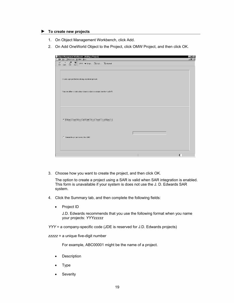
1. On Object Management Workbench, click Add.
2. On Add OneWorld Object to the Project, click OMW Project, and then click OK.
3. Choose how you want to create the project, and then click OK.
The option to create a project using a SAR is valid when SAR integration is enabled. This form is unavailable if your system is does not use the J. D. Edwards SAR system.
4. Click the Summary tab, and then complete the following fields:
• Project ID
J.D. Edwards recommends that you use the following format when you name your projects: YYYzzzzz
YYY = a company-specific code (JDE is reserved for J.D. Edwards projects)
zzzzz = a unique five-digit number
For example, ABC00001 might be the name of a project.
• Description
• Type
• Severity
19

• Product System Code
• Release
5. Click the Dates tab, and then complete the following field:
• Planned Completion Date
6. Click the Category Codes tab, and then complete the following optional fields:
• Category Code 1 through Category Code 10
7. Click the Attachments tab, and then add optional text comments to document the new project.
8. Click OK.
Changing Project Properties
You can view and modify the following properties of any project that you select:
• Description
• Type
• Severity
• Product system code
• Release information
• Start date
• Planned completion date
• Category codes
• Text attachments
► To change project properties
1. On Object Management Workbench, click a project, and then click Select.
You can also click the Design button in the center column.
2. On Project Revisions, click the Summary tab, and then revise the information in the following fields:
• Description
• Type
• Severity
• Product System Code
• Release
3. Click the Dates tab, and then revise the information in the following fields:
20

• Date Started
• Planned Completion Date
4. Click the Category Codes tab, and then revise the information in the following optional fields:
• Category Code 1 through Category Code 10
5. Click the Attachments tab, and then add optional text comments to document the project.
6. Click OK.
Advancing Projects
After development is complete for all objects in a project, the status of the project must be advanced to send the project through the development cycle. Changing the status of a project might affect the allowed actions of certain roles. The OMW can be configured to allow users, based on their roles, to perform specific actions when a project is at a specific status. For example, a user who is assigned to a project in the role of developer might be able to perform the following actions before the project is advanced: check out, design, and check in. However, after the project is advanced to the next status, a developer might not be able to perform any actions at all.
Changing the status of a project can also initiate actions, such as transferring objects in the project and deleting from the system objects that have been marked for removal. You cannot advance a default project.
Before You Begin Ensure that all of the objects in a project are checked in. This includes objects in
projects that are inheriting a token. In SAR-based systems, ensure that you complete all required SAR fields.
► To advance projects
1. On Object Management Workbench, click the project to be advanced.
2. Click the Advance Project button in the center column.
3. Click the field labeled >>>, and then enter the desired project status.
Your choices are limited, based upon the current status of the project and on your company's specific procedures, which are defined in the OMW Configuration application.
Note Turn on the Validate Only option to validate the status change without actually advancing the status of the project. This option allows you to verify that the project is valid before attempting any object transfers. Any projects that are linked to it through token inheritance are validated at this time as well.
4. Click OK.
If you did not turn on the Validate Only option, the system advances the project status and initiates any required object transfers and deletions. Otherwise, the system validates only the project status.
21
Use the OMW logging system to view any errors that occurred during the status change. If you cannot advance the project, verify the following:
• Verify that all of the objects in the project are checked in. This includes objects in projects that are inheriting a token.
• If you are using a SAR system, ensure you have completed all of the required fields in the SAR.
Adding Existing Projects to a Project
Besides objects and users, projects can contain other projects. You can add a project to a project, or, if the target project and the project to be added both appear in your project window, you can move the project to be added under the target project using drag-and-drop. The methods for adding and moving projects are identical to the methods for adding and moving objects.
See Also Adding Objects to Projects
Moving Objects
Deleting Projects
When you delete a project, the system removes all objects and owners from the project. The project is then completely deleted from the system.
If you delete a project that contains objects that are checked out, the system erases the check-out on each object before deleting the project. If the project holds any tokens, the system releases them at this time, as well.
► To delete projects
1. On Object Management Workbench, click a project, and then click Delete.
The system confirms the deletion.
2. Click OK in the Delete Confirm query.
Creating Objects
You can create a variety of objects with the OMW, including:
• Applications
• Business functions
• Data structures
• Tables
• Business views
• Data and menu items
• User defined codes (UDCs)
• Workflow processes
This topic describes how to create objects in general.
22

See Also OneWorld Enterprise Workflow Management documentation for instructions for
creating workflow processes
► To create objects
1. From the Object Management Workbench, click Add.
2. On Add OneWorld Object to the Project, click the object type that you want to create, and then click OK.
The Add Object form appears. The contents of this form vary based on the type of object that you are creating.
3. On Add Object, complete the fields as appropriate for the type of object you are creating, and then click OK.
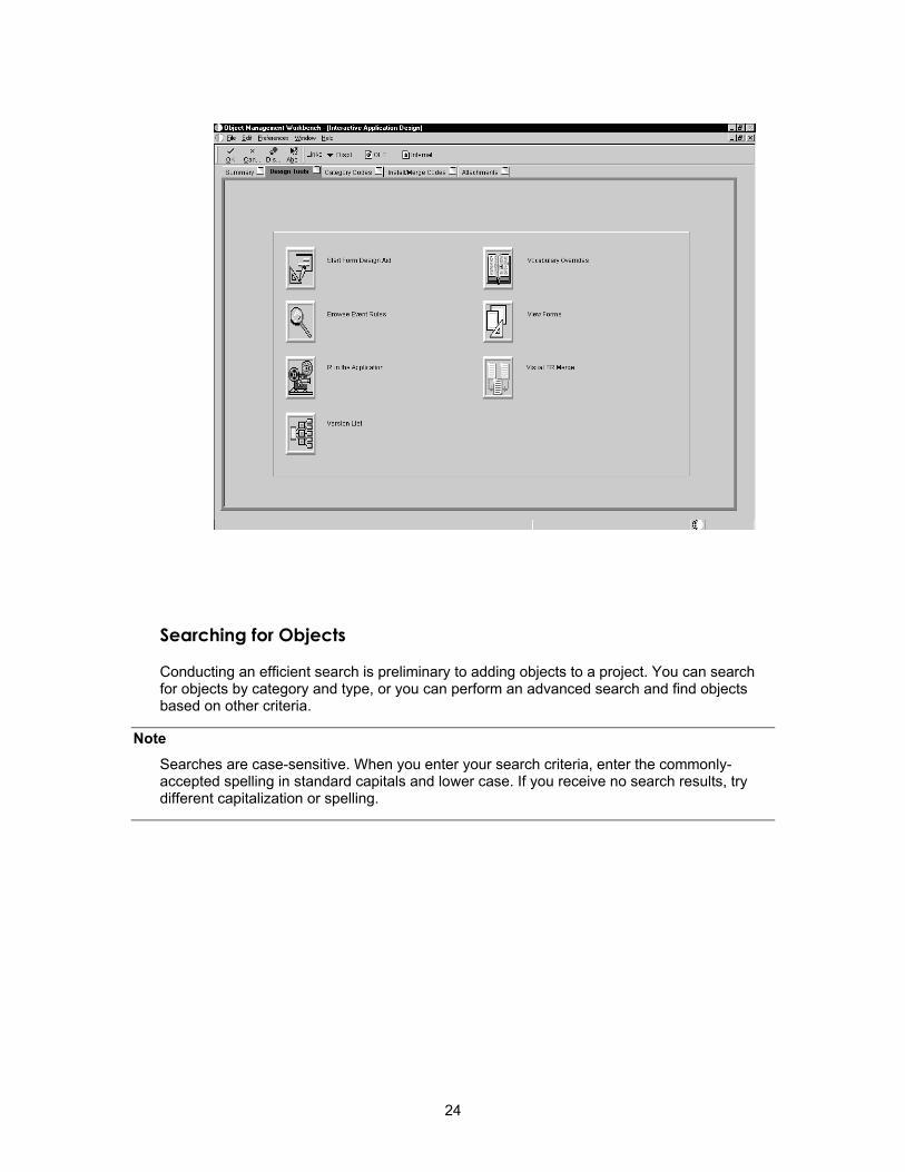
Depending on the object that you are creating, a design form might appear that provides the functions that you need to design the object. For example, if you create an interactive application, the Interactive Application Design form appears. Click the Design Tools tab to access the buttons that launch Form Design Aid, Work with Vocabulary Overrides, Work with Interactive Versions, and so on.
23
Searching for Objects
Conducting an efficient search is preliminary to adding objects to a project. You can search for objects by category and type, or you can perform an advanced search and find objects based on other criteria.
Note Searches are case-sensitive. When you enter your search criteria, enter the commonly-accepted spelling in standard capitals and lower case. If you receive no search results, try different capitalization or spelling.
24
► To search for objects
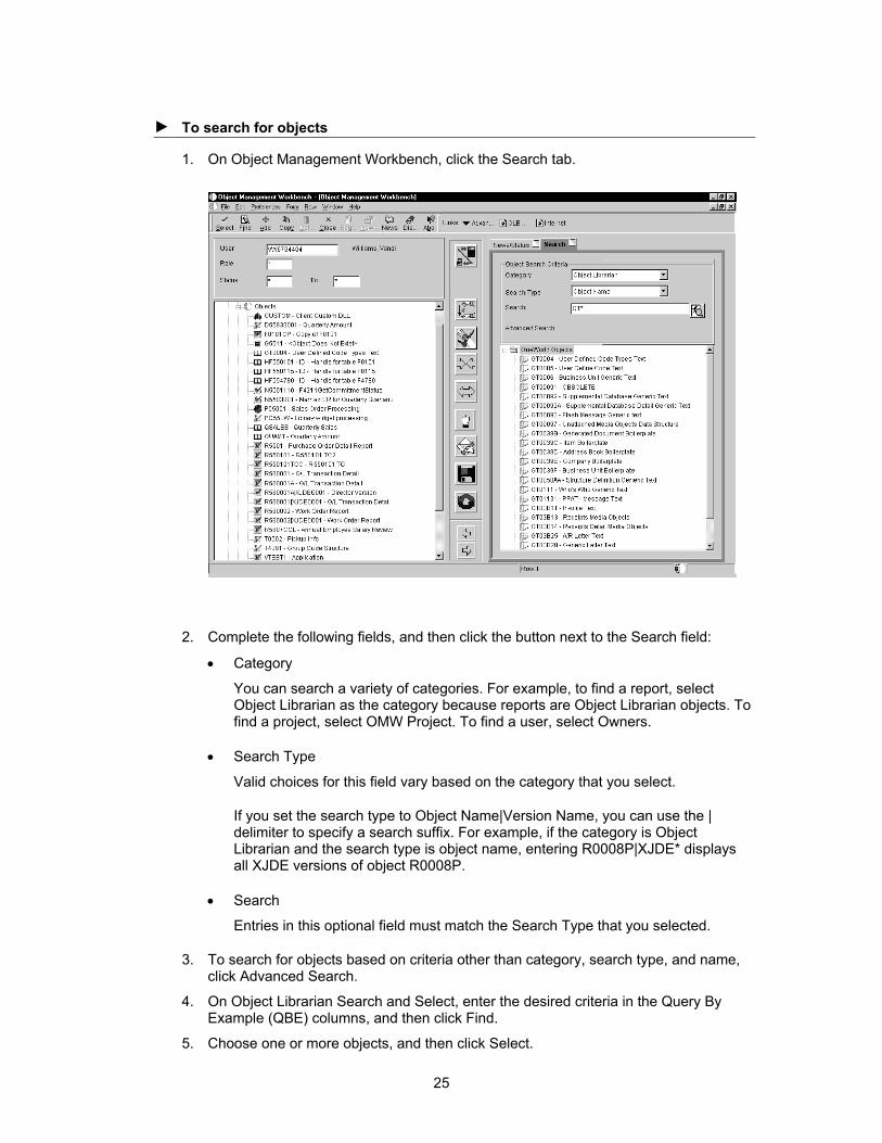
1. On Object Management Workbench, click the Search tab.
2. Complete the following fields, and then click the button next to the Search field:
• Category
You can search a variety of categories. For example, to find a report, select Object Librarian as the category because reports are Object Librarian objects. To find a project, select OMW Project. To find a user, select Owners.
• Search Type
Valid choices for this field vary based on the category that you select.
If you set the search type to Object Name|Version Name, you can use the | delimiter to specify a search suffix. For example, if the category is Object Librarian and the search type is object name, entering R0008P|XJDE* displays all XJDE versions of object R0008P.
• Search
Entries in this optional field must match the Search Type that you selected.
3. To search for objects based on criteria other than category, search type, and name, click Advanced Search.
4. On Object Librarian Search and Select, enter the desired criteria in the Query By Example (QBE) columns, and then click Find.
5. Choose one or more objects, and then click Select.
25
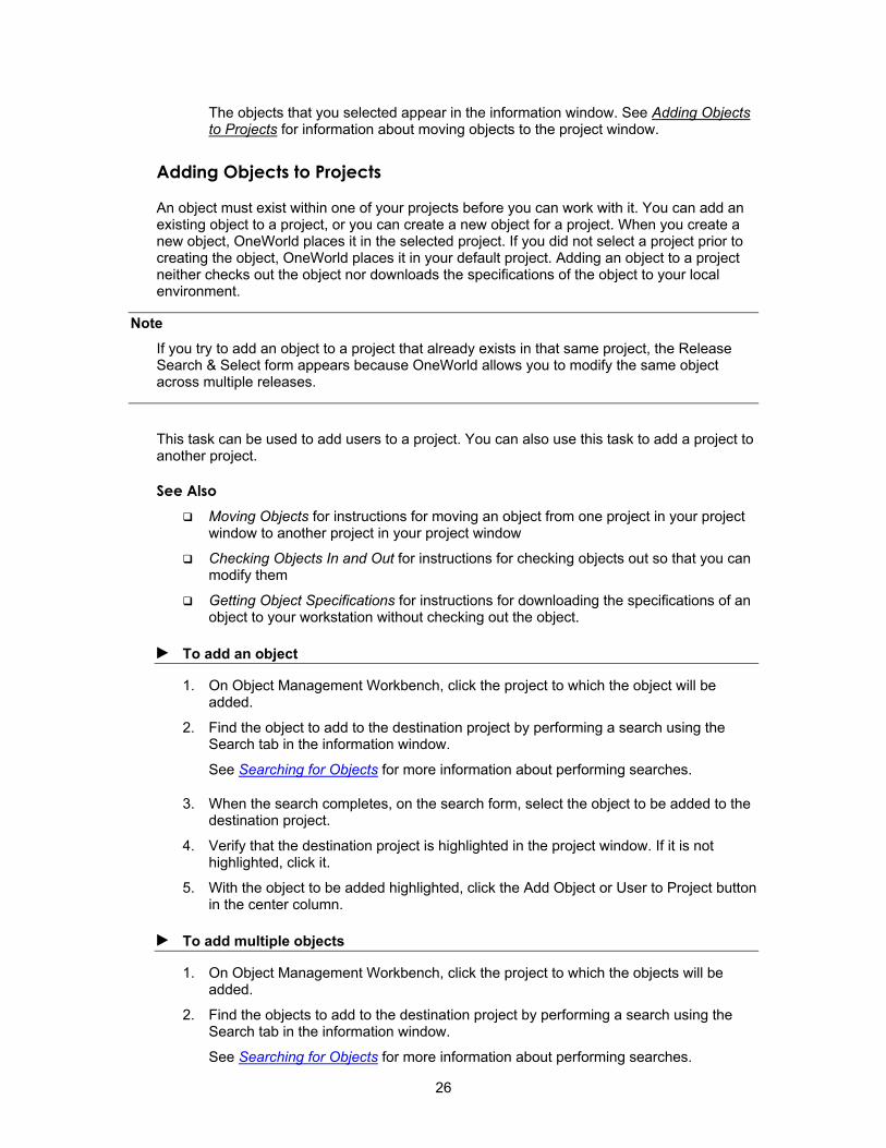
The objects that you selected appear in the information window. See Adding Objects to Projects for information about moving objects to the project window.
Adding Objects to Projects
An object must exist within one of your projects before you can work with it. You can add an existing object to a project, or you can create a new object for a project. When you create a new object, OneWorld places it in the selected project. If you did not select a project prior to creating the object, OneWorld places it in your default project. Adding an object to a project neither checks out the object nor downloads the specifications of the object to your local environment.
Note If you try to add an object to a project that already exists in that same project, the Release Search & Select form appears because OneWorld allows you to modify the same object across multiple releases.
This task can be used to add users to a project. You can also use this task to add a project to another project.
See Also Moving Objects for instructions for moving an object from one project in your project
window to another project in your project window
Checking Objects In and Out for instructions for checking objects out so that you can modify them
Getting Object Specifications for instructions for downloading the specifications of an object to your workstation without checking out the object.
► To add an object
1. On Object Management Workbench, click the project to which the object will be added.
2. Find the object to add to the destination project by performing a search using the Search tab in the information window.
See Searching for Objects for more information about performing searches.
3. When the search completes, on the search form, select the object to be added to the destination project.
4. Verify that the destination project is highlighted in the project window. If it is not highlighted, click it.
5. With the object to be added highlighted, click the Add Object or User to Project button in the center column.
► To add multiple objects
1. On Object Management Workbench, click the project to which the objects will be added.
2. Find the objects to add to the destination project by performing a search using the Search tab in the information window.
See Searching for Objects for more information about performing searches.
26

3. Verify that the destination project is highlighted in the project window. If it is not highlighted, click it.
4. From the Row menu, choose Advanced, and then choose Add All Objects.
The system adds all of the objects that fit the search criteria to the project that you selected in step 1.
27
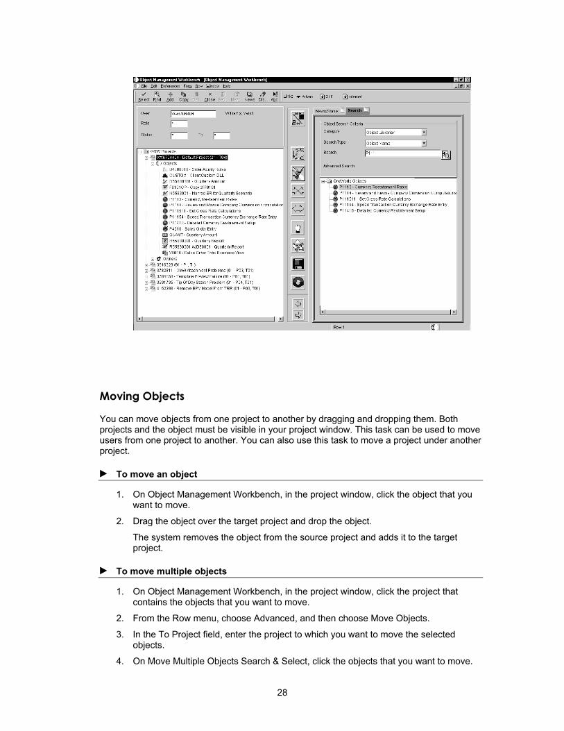
Moving Objects
You can move objects from one project to another by dragging and dropping them. Both projects and the object must be visible in your project window. This task can be used to move users from one project to another. You can also use this task to move a project under another project.
► To move an object
1. On Object Management Workbench, in the project window, click the object that you want to move.
2. Drag the object over the target project and drop the object.
The system removes the object from the source project and adds it to the target project.
► To move multiple objects
1. On Object Management Workbench, in the project window, click the project that contains the objects that you want to move.
2. From the Row menu, choose Advanced, and then choose Move Objects.
3. In the To Project field, enter the project to which you want to move the selected objects.
4. On Move Multiple Objects Search & Select, click the objects that you want to move.
28
5. Click Select.
The system moves the objects from the source project to the target project. This process might take a while, depending on the number of objects that you selected.
Removing Objects from Projects
This action removes the reference to the object from the project; it does not actually delete the object. This task also can be used to remove users from a project.
► To remove objects from projects
1. On Object Management Workbench, select an object in the project window.
2. Click the Remove Object or User from Project button in the center column.
Deleting Objects
You can delete any object from the server that is defined for the current status. You can also mark an object for deletion from its transfer locations upon project advancement or from its current save location (the location where the system saves the object when you click the Save button in the center column of the OMW).
You can also use this task to remove the specifications for Object Librarian object from your workstation.
When you select Delete Object from Server for a non-Object Librarian object, the system deletes the object from locations that are defined in the transfer activity rules when you click OK. If you select Mark Object to be Deleted from Transfer Locations, the system deletes the object from any other configured locations when the project advances.
For an Object Librarian object, you can delete the local and save specifications. If the Object Librarian object is checked in, you can delete the checked-in version of this object by selecting Delete Object from Server. If you select Mark Object to be Deleted from Transfer Locations, the Object Librarian object is deleted from its transfer locations, which are defined in the transfer activity rules when the Project Status is advanced.
► To delete objects
1. On Object Management Workbench, choose an object in the project window.
2. Click Delete.
The Delete Object Confirmation form appears. Your available options vary depending on the object type and whether the object has been checked in.
3. Select one or more of the following options, and then click OK:
• Delete Object from Server
Click View Locations for a list of locations from which the object is deleted when you select this option. This action occurs as soon as you click OK.
• Delete Object Locally
This action occurs as soon as you click OK.
• Delete Object from the SAVE location
This action occurs as soon as you click OK.
29

• Mark Object To Be Deleted From Transfer Locations
Objects marked to be deleted from transfer locations appear in bold letters in the project window. They are deleted from the transfer locations when the project status is advanced.
• Remove Object from ALL locations
This option selects all of the above options.
Getting Object Specifications
To download checked-in object specifications from the server that is defined for the current status, select the object and click the Get button in the center column. Use this function when someone else has been working on the object and you want to see the changes, or when you have made changes to the object but want to abandon them in favor of another version of the object.
The Get button allows you to get the specifications for objects that reside in your path code only. However, you can download the specifications of an object that resides in other areas of the system as well. For example, you might want to get the specifications for an object as it existed in a previous software release. Use the advanced get feature to specify the location of the object that you want to download.
Note If you want to review the object and not save any changes, use the Get button to copy the latest specifications to your local workstation instead of checking out the object and then erasing the checkout.
► Using advanced get
1. On Object Management Workbench, choose an object in the project window.
2. From the Row menu, select Advanced, and then select Get.
The system verifies that you want to overwrite your local specifications.
3. On Path Code Search & Select, click Find.
4. Choose the location of the object that you want to get, and then click Select.
Checking Objects In and Out
You can check out an Object Librarian object that resides in your projects, provided that the token for the object is either available or held by the project in which the object currently resides. Only one user at a time can check out an object. Check out fails if the object is already checked out or if the token is unavailable. If the token is unavailable, you can join the token queue for the desired object. If you join the token queue, you will be notified when the token is available and your project will receive the token.
Check in an object when you want to upload its specifications to the server and make it publicly available. When you check in an object, the system records the project in which the object resides and ensures that only changes made under the current project are transferred when the project is advanced to a status that triggers a transfer. If you move an object from
30
one project to another using the drag-and-drop method, the system tracks the change and records the new project for the object. However, consider the following scenario:
• You add an object to a project and check it out.
• You change the object and check it in.
• You use the right-facing arrow in the center column to remove the object from the project.
• You later add the object to a different project.
In this scenario, the system cannot track the object because it passes out of a project completely. Therefore, when you advance the second project, if the system needs to transfer the object as part of the advance, the transfer will fail because the object's last known check-in project location and its current project location do not match. When you drag-and-drop an object, the system updates its tables in such a way that the transfer can occur. This is not the case when you remove an object from a project and then add it to a different project later.
If an object is checked out, you can erase the check out. When you erase a checkout, local changes are not uploaded to the server. Erasing the checkout for an object does not release its token, but it does allow other developers who are assigned to the same project to check out the object.
See Also Working with Tokens
► To check objects out
1. On Object Management Workbench, select an object in the project window.
2. Click the Checkout button in the center column.
The OMW indicates that an object is checked out by superimposing a checkmark over the icon for the object. Additionally, data about the object that appears in the information window is updated to reflect its checked out status.
Note If the object is unavailable, the system asks if you want to be added to the token queue for the object. If you choose to join the queue, the system alerts you when the token is released and assigns the token to your project. To determine which project holds the token for an object, select the object in the project window and click the News/Status tab in the information window. Additionally, if you have joined a token queue, your position in the queue appears here.
► To check objects in
1. On Object Management Workbench, select a checked-out object in the project window.
2. Click the Check-in button in the center column.
The OMW indicates that an object is checked in by removing the checkmark that is superimposed over the icon for the object when it was checked out.
31

► To erase checkouts
1. On Object Management Workbench, select a checked-out object in the project window.
2. Click the Erase Checkout button in the center column.
The OMW indicates that an object is no longer checked out by removing the checkmark that is superimposed over the icon for the object when it was checked out.
Changing Objects
When you create an object using the Object Management Workbench (OMW), the OMW allows you to define the properties of the object. The OMW also provides access to design tools and system actions for the object. Similarly, after the object has been created, you can use the OMW to modify the object and its specifications.
Your system administrator can also specify a separate save location that is different from your local environment and from the location of the object on the server. Save objects to this location by selecting the object and clicking the Save button in the center column. Retrieve an object from its save location by selecting the object and clicking the Restore button in the center column. Note that the save location for the object must be different from its system location.
You must check out the object before you modify it to be able to check the object back in and upload the changes.
As users modify objects, the changes exist only in their local environments until they either save the object to its save location or check in the object to its system location.
► To change objects
1. On Object Management Workbench, choose an object in the project window.
2. Click the Design button in the center column.
An appropriate design form for the object appears. The current properties of the object appear on the form.
3. Make the necessary changes to the object, and then click OK.
Maintaining Objects in Multiple Software Releases
Same-named objects in different software releases can be modified in the OMW in the same project. After adding the objects to the project, you can maintain them independently, or you can update one to match the other. When working on objects from separate releases, the OMW handles save and check-in file paths for you, based on the Object Management Configuration. You perform the necessary modifications and use the OMW functions as you would normally.
Caution Changing and maintaining objects in multiple releases can cause problems due to OneWorld object interdependencies. Changing an object in one version and then updating the object in another version to match might cause dependent objects to malfunction.
32

Before You Begin Determine the paths of the objects that you modify initially.
► To add same-named objects to a project
1. On Object Management Workbench, add the first object to the project.
Note The object is added to the project at the current release level of your OneWorld software.
2. Add the same object to the project again.
3. On the Release Search and Select form, click Find.
All available releases for which the object can be added to the project appear.
4. Click the release you want, and then click Select.
The object is added to the project for the selected release level.
► To change the release level of an object on your project
1. On Object Management Workbench, choose Advanced from the Row menu, and then choose Change Release.
2. On the Release Search and Select form, click Find.
All available releases for which the object can be added to the project appear.
3. Click the release that you want, and then click Select.
The object is added to the project for the selected release level.
► To update an object to match another object
1. Check out the object A from release A.
2. Modify the object.
3. Check in the modified object A.
4. Check out the object B from release B.
5. Select object B, choose Advanced from the Row menu, and then choose Get.
6. On Path Code Search & Select, find and select the path code in which the release A version of the object was checked in, and then click Select.
In your project, the release B version of the object is modified to match the release A version of the object.
7. Check in object B.
33

► To update different objects in different releases
1. Check out the object from release A.
2. Modify the object.
3. Check in the modified object.
4. Check out the object from release B.
5. Modify the object.
6. Check in the modified object.
Working with Tokens
In the Object Management Workbench (OMW), Object Librarian objects use tokens to minimize the possibility of one user overwriting another user's changes. Each object has a single token, and it is associated with a project when the object is checked out. Checking in the object does not release the token; instead, the token is released when the status of the project changes to a level determined by your system administrator. At that time, another developer can check out the object and receive the token.
The following three actions are allowed while your project holds the token:
• Allow another project to inherit the token. This forces both projects to be advanced together as if they were one project and allows multiple corrections to a project to be applied to a single object. No matter how many projects have inherited the token, however, only one user at a time can check out the object. For a project to successfully inherit a token, the target project must be at the same status as the source project.
• Switch the token to another project. After the token is switched, the project that loses the token will be placed in the token queue as the first project that is waiting for the token. When you configure the OMW, token switching should be restricted to a specific user role so that you can maintain object security.
• Release the token. An owner on the project can give up the token and allow the next project in the queue to receive it.
The Object Management Workbench might have been configured to release tokens for different object types at different project status levels. Therefore, all object types might not give up their tokens during the same change in project status.
Understanding the Token Queue
The OMW attempts to acquire a token for an object when you check out an object. If the token is unavailable, the information window displays information about the token, such as which project currently holds it, the user who checked it out, and when the user checked it out. Additionally, you can join the token queue so that you are notified when the token is released and your project is assigned the token. Projects in the token queue are assigned the token in the order in which the users requested the token. Additionally, after joining the token queue, you can choose to inherit the token.
When a project has a token, the token stays with that project until the project advances to a status that is configured in the activity rules for release of the token or until it is switched or released manually. When the token is released, the next project in the token queue is notified and assigned the token. Each Object Librarian object has one token per release.
34
If you join a token queue and then decide later that you do not need the token, remove the object from your project to relinquish your position in the queue.
► To view a token queue
1. On Object Management Workbench, click an object in the project window.
2. From the Row menu, choose Advanced, and then choose Token Queue.
The Token Queue form for the View Object appears. The form shows which project currently holds the token and which projects, in order, are in the queue.
See Also Inheriting Tokens
Inheriting Tokens
Token inheritance can be useful when developers have the same object in multiple projects for which they would like to implement changes simultaneously, without having to wait for other projects that are holding the token to progress through the project life cycle.
To inherit tokens, both the project holding the token and the inheriting project must be at the same project status. After a token is inherited, these projects will be linked and will automatically advance in project status together. Therefore, if the project status of one project is advanced, the project status of its linked project also advances. If one or more projects are linked through token inheritance, ensure that all development in the linked projects is complete before you advance the projects. The user who is attempting to advance the project must be assigned a role that permits this action in all of the linked projects, or the advance attempt will fail.
All project advancement requirements must be met for all projects that are linked through token inheritance; if one project fails to advance, OMW does not advance any of the other linked projects. If an advancement failure occurs, review the logs for all of the linked projects to determine where the errors occurred.
► To inherit tokens
1. Attempt to check out an object for which another project holds the token.
The system asks you whether you wish to enter the token queue for the object or inherit the token.
2. Choose to inherit the token, and then click OK.
Note If you have inherited the token but cannot check out the object, the object is already checked out by another user. You cannot check out the object until the other user checks it in or until checkout is erased. This prevents you from overwriting changes when you inherit the token.
Switching Tokens
A project owner whose role allows switching tokens might take the token from the project that currently holds it and assign it to another project. Switching tokens might be necessary when you need to make an emergency change. If a change in another project needs to be
35

implemented to an object in your project, you can switch the token to the other project to allow the change.
Note After the token has been returned, the user from whom the token was taken can save the object, check the object out, and then restore the object to return the object to its previous state before switching. However, the user must manually implement any changes made during the switch.
To switch a token, you must be an owner in both the holding and the requesting projects. Your role in both projects must be one that allows the action, switch token, at the current status of the project and for the object type.
Before You Begin The token requester should attempt to check out the object and then join the token
queue.
► To switch a token
1. On Object Management Workbench, select the object that has the token that you want to switch.
2. Click the Switch Token button on the central column.
3. On Project Token Queue Search and Select, click Find.
A list of projects in the token queue appears.
4. Choose the project to which you want to give the token, and then click Select.
The current token owner should save the object before you switch the token.
Releasing Tokens Manually
You can release a token manually if you decide you do not need to modify an object. Additionally, you can release the token if you want to allow the next person in the token queue to check out the object for development. If you have made changes to an object and checked it in, another developer in another project must refrain from checking in the object until after your project has been promoted to a status where the system transfers the object to the next path code, or your changes will not be transferred.
See Also Understanding the Token Queue
Advancing Projects
► To release tokens manually
1. On Object Management Workbench, either erase the check-out or check in the object that has the token that you want to release, if appropriate.
2. Select the object, and then click the Release Token button in the center column.
36

Searching for Users
Conduct an efficient search before you add users to a project. You can search for user names or Ids, or you can perform an advanced search and find users based on their class or group.
Note Searches are case-sensitive. When entering your search criteria, enter the commonly-accepted spelling in standard capitals and lower case. If you receive no search results, try different capitalization or spelling.
► To search for users by name or ID
1. In Object Management Workbench, click the Search tab.
2. Complete the following fields:
• Category
Enter Owner.
• Search Type
• Search
Entries in this optional field must match the search type that you selected.
37
You can use | to specify a search suffix. For example, if the category is Owners and the search type is Address Book#|Search Type, entering *|E displays all entries in the Address Book with a search type of E for employee.
3. Click the Search button next to the Search field.
► To search for users by class or group
1. On Object Management Workbench, click the Search tab.
2. Complete the following fields:
• Category
Enter Owner.
• Search Type
3. Click Advanced Search.
4. On OneWorld User ID Search and Select, complete one or more of the QBE columns and click Find.
5. Choose the users that you want, and then click Select.
Adding Users to Projects
To affect a project and the objects within that project, a user must be added to the project. When added to the project, a user is assigned a specific role. This role dictates the kind of actions that the user can perform. A user can be added to a project more than once with different roles. Additionally, some roles can be associated with several users. For instance, a project might include several developers.
► To add users to projects
1. On Object Management Workbench, click the project to which you want to add the users.
2. Set up a list of users to add to the destination project by performing a search using the Search tab in the information window.
See Searching for Users for more information about performing searches.
3. On the search form, select the user to be added to the destination project.
4. Verify that the owner's node in the destination project in the project window is highlighted. If it is not highlighted, click it.
5. With the user to be added highlighted, click the Add Object or User to Project button in the center column.
6. On Add User to Project, complete the following fields, and then click OK:
• Role
• Lead
Note To add a user in more than one user role, repeat the add user procedure and select a second user role for the same user. Different functions are enabled for different
38

user roles, according to their allowed (user) actions. These actions are configured by the administrator for your project using the configuration program of the OMW.
Removing Users from Projects
Removing a user from a project does not delete the user from the system.
► To remove users from projects
1. On Object Management Workbench, select a user in the project window.
2. Click the Remove Object or User from Project button in the center column.
Changing User Properties
You can modify the following user properties:
• User Role
• Estimated Hours
• Lead
► To change user properties
1. On Object Management Workbench, select a user (owner) in the project window, and then click Select.
2. On Project User Details, complete the following fields, and then click OK:
• User Role
• Project Lead
• Estimated Hours
Working with Attachments
The Object Management Workbench (OMW) allows you to add text, graphic, OLE, and file attachments to projects and to Object Librarian objects within projects. These attachments are available only through the OMW; they neither affect the way in which the object functions, nor are they available when a user employs the object. You use this feature to document the creation, purpose, and intended use of objects in the system.
See Also Media Object Attachments in the OneWorld Foundation documentation for
information about adding and working with attachments
Media Objects and Imaging in the System Administration documentation for information about enabling media objects
Creating a Media Object Data Structure
39
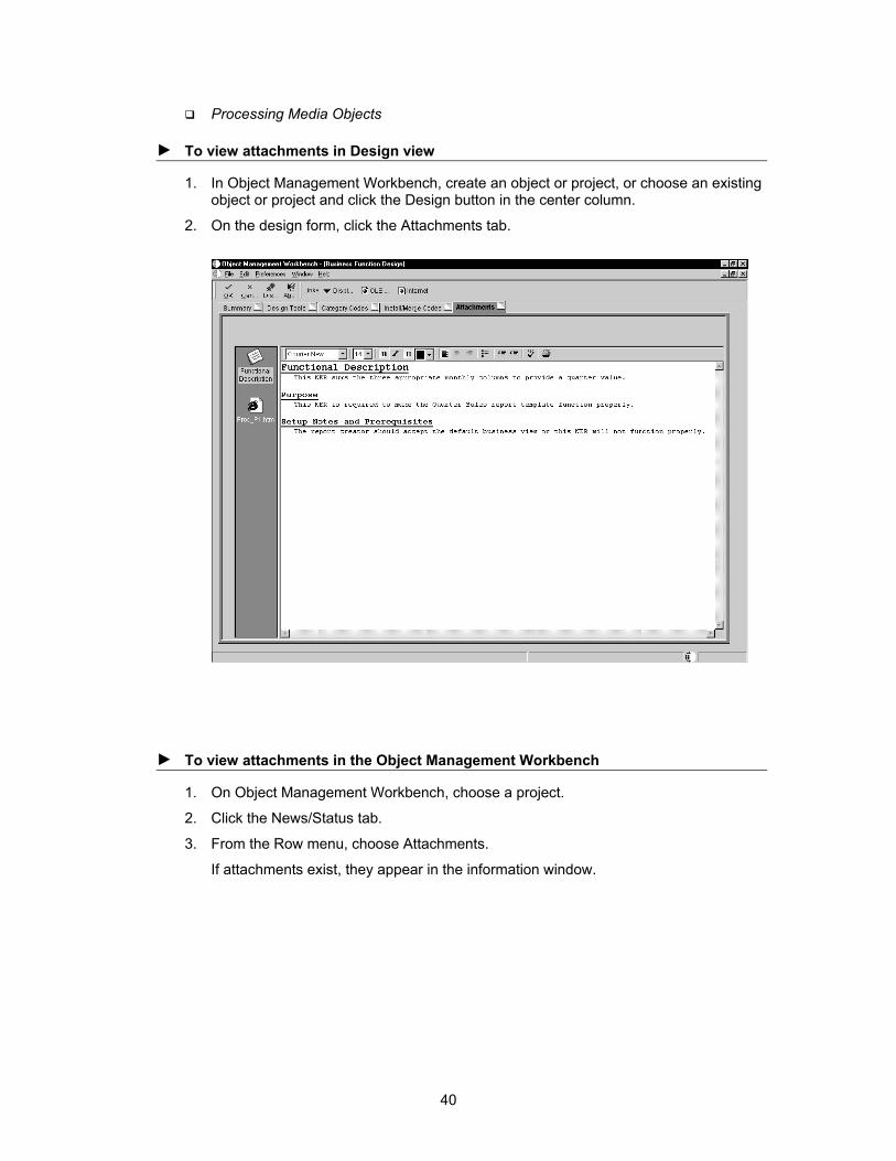
Processing Media Objects
► To view attachments in Design view
1. In Object Management Workbench, create an object or project, or choose an existing object or project and click the Design button in the center column.
2. On the design form, click the Attachments tab.
► To view attachments in the Object Management Workbench
1. On Object Management Workbench, choose a project.
2. Click the News/Status tab.
3. From the Row menu, choose Attachments.
If attachments exist, they appear in the information window.
40
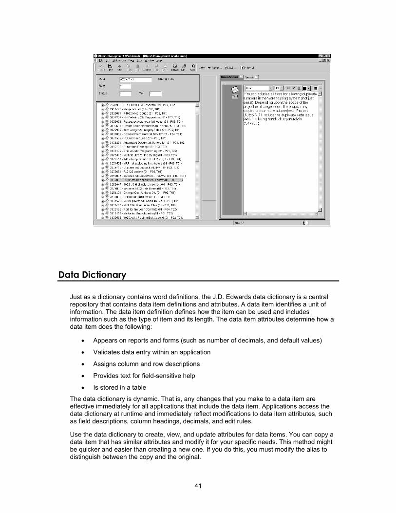
Data Dictionary
Just as a dictionary contains word definitions, the J.D. Edwards data dictionary is a central repository that contains data item definitions and attributes. A data item identifies a unit of information. The data item definition defines how the item can be used and includes information such as the type of item and its length. The data item attributes determine how a data item does the following:
• Appears on reports and forms (such as number of decimals, and default values)
• Validates data entry within an application
• Assigns column and row descriptions
• Provides text for field-sensitive help
• Is stored in a table
The data dictionary is dynamic. That is, any changes that you make to a data item are effective immediately for all applications that include the data item. Applications access the data dictionary at runtime and immediately reflect modifications to data item attributes, such as field descriptions, column headings, decimals, and edit rules.
Use the data dictionary to create, view, and update attributes for data items. You can copy a data item that has similar attributes and modify it for your specific needs. This method might be quicker and easier than creating a new one. If you do this, you must modify the alias to distinguish between the copy and the original.
41
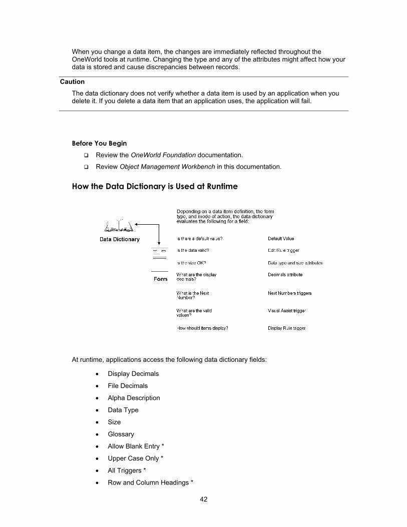
When you change a data item, the changes are immediately reflected throughout the OneWorld tools at runtime. Changing the type and any of the attributes might affect how your data is stored and cause discrepancies between records.
Caution The data dictionary does not verify whether a data item is used by an application when you delete it. If you delete a data item that an application uses, the application will fail.
Before You Begin Review the OneWorld Foundation documentation.
Review Object Management Workbench in this documentation.
How the Data Dictionary is Used at Runtime
At runtime, applications access the following data dictionary fields:
• Display Decimals
• File Decimals
• Alpha Description
• Data Type
• Size
• Glossary
• Allow Blank Entry *
• Upper Case Only *
• All Triggers *
• Row and Column Headings *
42

The application retrieves field information from the data dictionary. Fields marked with an asterisk (*) can be overridden in Forms Design and Report Design. In these instances, the application retrieves the overrides, if any exist.
Naming Data Items
The following illustrates the naming components for a data item:
After a data item is created, you can change only the alpha description; you cannot change the data item and alias. When you add a data item, the data dictionary edits the data item and alias fields to ensure that they are unique.
See the Development Standards Application Design Guide for naming standards.
Storing the Data Dictionary and Data Dictionary Items
The data dictionary is stored in the following two places:
• The central object data dictionary is stored in a relational database. All changes to the data dictionary that will be replicated a must be done here.
• The replicated data dictionary allows each workstation to have a set of data dictionary tables stored in specification tables on the client machine.
Data dictionary items reside on enterprise (logic) servers in relational database tables. Workstations retrieve from the publisher data dictionary (the relational database tables) only those data items that are necessary for the applications that you are using. This replication occurs when you use an application for the first time after installing OneWorld. This data dictionary information is stored on your workstation in a permanent cache under the same local path code and spec directory as the following global tables:
• glbltbl.xdb (references for the data)
• glbltbl.ddb (the data items)
If data items have been changed and you want to replicate the changes to workstations immediately, you must use the Data Replication (P98DREP) application. When you have data replication set up and an item is changed, the next time a machine that is set up as a subscriber signs on to OneWorld, the permanent cache for that data item will be deleted. Then, the next time a user accesses an application that has that changed data item, OneWorld detects that the information is not in the permanent cache and retrieves the information from the publisher data dictionary (the relational database tables).
If you are using OneWorld and World coexistence, you must maintain two data dictionaries. You cannot share one dictionary because, in World, the $ is reserved for business partners and is used for the beginning of an alias. The $ does not compile and thus cannot be shared with OneWorld. Some of the file formats in World and OneWorld are also different.
See Also Data Dictionary Administration in the System Administration documentation
43

Glossary Items
Glossary items are items that cannot be attributes in tables. Glossary items are typically used as information messages.
Error Messages
Error messages used in OneWorld are stored as data items. Use the data dictionary glossary item application to display error messages because you do not need to use all the fields required for regular data items.
Understanding Default Triggers
A default trigger is an editing or display routine that is attached at the dictionary level and initiated at runtime. Default triggers are reusable objects and, therefore, automatically associated with each application that uses the data item. Default triggers leverage your time and code because you can create the business logic only once and then use it within multiple applications. Default triggers ensure accuracy and integrity of data across all applications.
You use triggers to do the following:
• Establish field default values
• Link data items to a user defined code (UDC) table of valid values
• Activate a visual assist search program when a user positions the cursor in a field. The types of visual assists are:
• Calendar
• Calculator
• Search and select of another file
• UDC
• Establish rules and procedures that are embedded in the editing and formatting of the data for a field
• Determine a next number scheme that developers should use when assigning a number to data
Using the Data Dictionary
You can create new data dictionary items and view existing ones with the Object Management Workbench or with the Work With Data Items program (P92001). After you create a data dictionary item, use Work With Data Items to define jargon and language translations for it. There is one point of entry for the data dictionary tool.
44
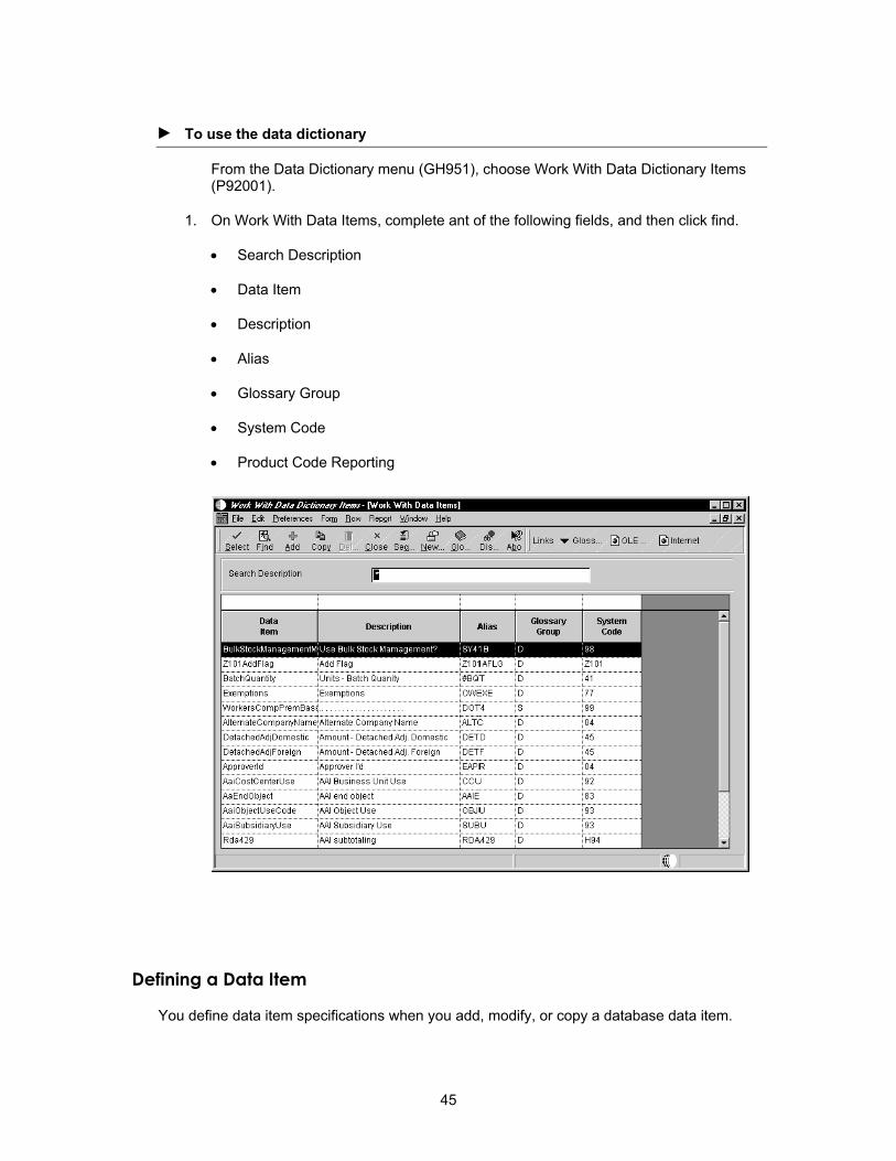
► To use the data dictionary
From the Data Dictionary menu (GH951), choose Work With Data Dictionary Items (P92001).
1. On Work With Data Items, complete ant of the following fields, and then click find.
• Search Description
• Data Item
• Description
• Alias
• Glossary Group
• System Code
• Product Code Reporting
Defining a Data Item
You define data item specifications when you add, modify, or copy a database data item.
45

Creating a Data Item
Data dictionary items are the building blocks of OneWorld objects. You create data dictionary items so that they can be used as fields on a form of an application, columns in a table, fields in a business view, members of a data structure, fields on a UBE, and so on.
► To create a data item
1. From the Object Management Workbench, click Add.
2. On Add OneWorld Object to the Project, choose the Data Item option, and then click OK.
The system asks whether you want to create a normal data dictionary item or a glossary data item. Glossary data items are used primarily for batch error messages.
3. To create a normal data dictionary item, click No.
The Data Items Specification form appears.
4. Complete the steps to name a data item.
Naming a Data Item
Once you have created a base data item, you must assign a unique name and attributes to this new data dictionary item before it can be included in an application.
46
► To name a data item
1. On Data Item Specifications, complete the following fields:
• Data Item
• Alias
• Glossary Group
2. Complete the steps to define general information.
Data Dictionary Naming Conventions
Whether you are an internal J.D. Edwards developer or a developer external to J.D. Edwards, you must use the naming conventions for data items. Adhering to these conventions ensures database integrity and prevents data items from being overwritten by other data items.
If you are creating a data item for use in both WorldSoftware and OneWorld, separate limitations and considerations are required that are not addressed in detail in this guide.
Data Item Name The data item name is a 32-character, alphabetical field that identifies and defines a data item. You must allow enough room in the field name for a 30 percent expansion of the English text for translation.
The data item name forms the C-code data name (for example, AddressNumber) that is used in business functions, data structures, and event rules.
When creating a J.D. Edwards data dictionary item, do not use a Y or Z in the first character of the data item name. Y and Z are reserved for Partners in Development business partners. (J.D. Edwards data items beginning with Y or Z might exist because they were created before the B73.2 release of OneWorld. These items will remain J.D. Edwards items.)
Blanks and the characters % & , . + are not allowed as part of the data item name in OneWorld.
You can also identify a data item by its alias or alpha description.
After you add a data item, you cannot change its name.
Data Item Name for an External Data Dictionary Item When creating an external data item, you must use a Y or Z in the first character of the data item name to distinguish an external data dictionary item from a J.D. Edwards data dictionary item.
The data item name can be a maximum of 32 alphanumeric characters, and it uses the following format:
Ysssdddddddddddddddddddddddddddd, where:
Y or Z designates an external data dictionary item and is the first digit of any J.D. Edwards-assigned external system code.
47
sss is the system code number. This number is either 55xx through 59xx for enterprise-level development of new modules, 60xx through 69xx for J.D. Edwards custom development, or another number that the Partners in Development system administrator assigns.
ddddddddddddddddddddddddddddd is a unique name for the data item.
Data Item Alias The data item alias is an 8-character alpha code. If the data dictionary item is exclusive to OneWorld applications, the alias is five or more characters in length. When you add a data item that will be used in a table by an RPG program, the data item alias must not exceed four characters.
The data item alias is used in searches, database routines (application program interfaces used in business functions), and Table Design when you create a table. For each table, a prefix is added to the alias, which makes it unique to this table. For example, ABMCU indicates that MCU is within the Address Book table (P01012).
When assigning an alias, do not begin the alias with TIP or TERM. Aliases that begin with TIP are reserved for OneWorld tips information; aliases that begin with TERM are reserved for term glossaries that are included in OneWorld guides.
Blanks and the characters % & , . + cannot be included as part of the data item alias in OneWorld.
You can also identify a data item by its data item name or alpha description.
After you add a data item, you cannot change its name or alias.
Alias for an External Data Dictionary Item An external data dictionary item is one that is created by a developer outside of J.D. Edwards for use in OneWorld. For external data items, the data dictionary alias can contain a maximum of eight alphanumeric characters, and it uses the following format:
Ysssdddd, where:
Y or Z designates external data dictionary item and is the first digit of any JDE-assign external system code.
sss is the system code number. This number is either 55xx through 59xx for enterprise-level development of new modules, 60xx through 69xx for J.D. Edwards custom development, or another number that the Partners in Development system administrator assigns.
dddd is a unique name for the data item.
Defining General Information
After you name a data item, you must provide additional general information on Data Item Specifications.
48

► To define general information
1. On Data Item Specifications, click the Item Specifications tab.
2. Complete the following required fields:
• Description
• System Code
• Data Type
• Control Type
• Row Description
This description is for the base language only, unless you update the description for another language.
• Column Title
This description is for the base language only, unless you update the description for another language.
• Size
• File Decimals
49

• Display Decimals
3. Complete the following optional fields:
• Class
• Item Occurrences
Item occurrences is used for arrays. It allows you to create an item as a child of another item. The data dictionary verifies that attributes are consistent between the parent and the child. If you change the parent item, the changes are duplicated in the child items. The data item names use the parent data item name and a number, such as a parent item ABC and child items ABC1, ABC2, and so on.
4. Click any of the following options to turn them on:
• Upper Case Only
• Row Security
• Allow Blank Entry
• Auto Include
• Do Not Total
5. Complete the steps to attach default triggers.
Attaching Default Triggers
You use triggers to initiate display and edit routines that are associated with data items at application runtime.
► To attach default triggers
1. On Data Item Specifications, click the appropriate tab to attach any of the following applicable triggers to a data item:
• Default Value
• Visual Assist
• Edit Rule
• Display Rule
• Next Numbers
• Smart Field
Although you can override any of these triggers in Forms Design in the Edit Control Properties, you should anticipate how they will be used most often.
Attaching a Default Value Trigger
A default value trigger automatically inserts a specified default value in a field when the following conditions are met:
50

• Control is exited
• Dialog is initialized
You use the default value trigger for fields in which the default value is appropriate in almost every situation. If a value is passed to this field through a processing option, business function, form interconnection, or data structure, or if the user enters a value, this default value will not be used.
► To attach a default value trigger
1. On Data Item Specifications, click the Default Value tab.
2. Click the following option to turn it on:
• Default Value
3. Enter the default value.
Attaching a Visual Assist Trigger
The following three types of triggers are available:
• Search form (flashlight)
• Calculator
• Calendar
Use a search form trigger to link a field to a search form for locating valid values. The search form must exist before you attach a search form trigger.
51

► To attach a visual assist trigger
1. On Data Item Specifications, click the Visual Assist tab.
2. On Visual Assist, click one of the following options:
• No Visual Assist
• Calculator
• Calendar
• Search Form
3. If you click Search Form, click the Browse button to select the form that you want to access for valid values.
52

If you attached a Search Form assist trigger, at runtime when you click the Search Form flashlight button, the selected form appears. You can enter search criteria and return with a valid value. These Search and Select forms are based on files, not UDC tables.
Attaching an Edit Rule Trigger
You use edit rule triggers to validate field values based on business functions or rules. For example, you can define a rule that does the following:
• Validates and compares a field with a particular value
• Ensures that a field value is within a specified range of values
• Links a field to a specific UDC Search and Select form
• Checks for Y and N values
► To attach an edit rule trigger for a business function
1. On Data Item Specifications, click the Edit Rule tab.
2. On Edit Rule, click one of the following options:
• Business Function
• Rule
53
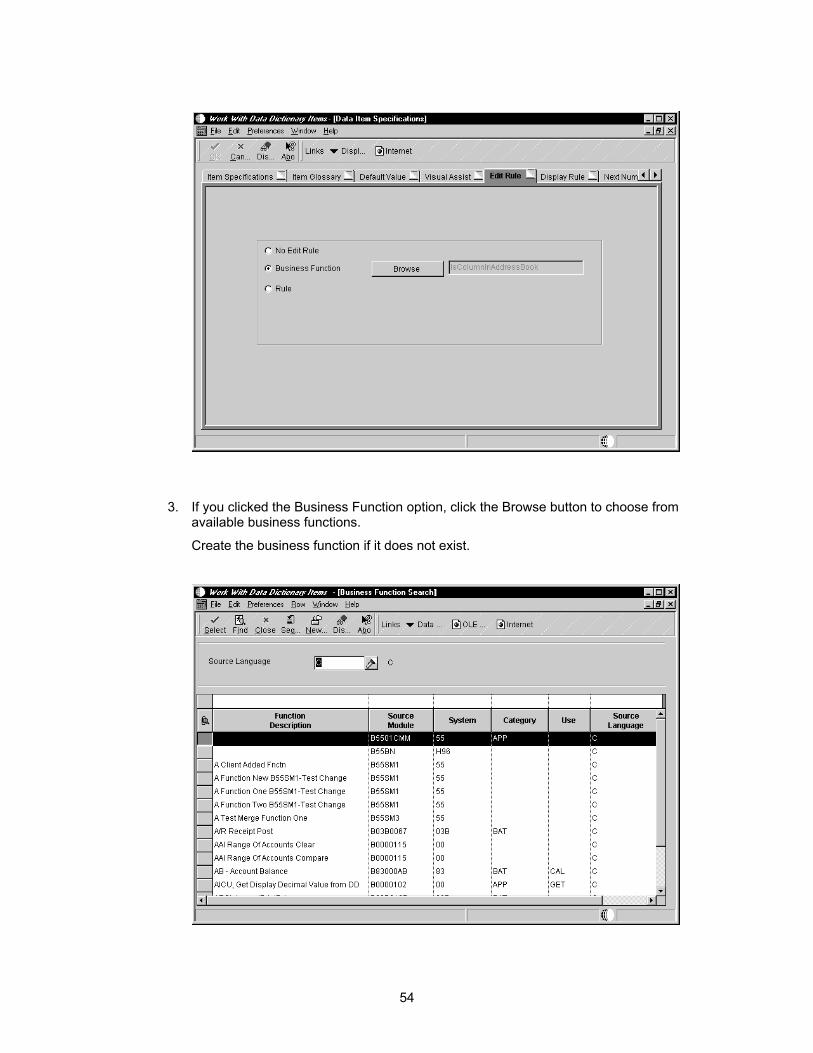
3. If you clicked the Business Function option, click the Browse button to choose from available business functions.
Create the business function if it does not exist.
54
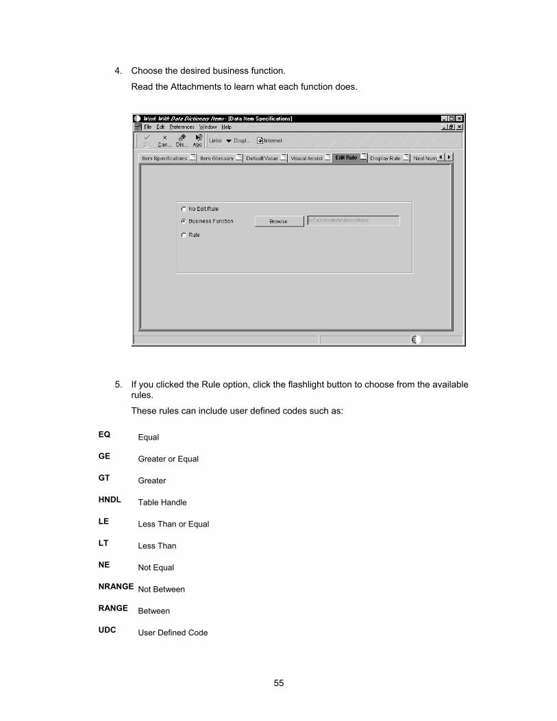
4. Choose the desired business function.
Read the Attachments to learn what each function does.
5. If you clicked the Rule option, click the flashlight button to choose from the available rules.
These rules can include user defined codes such as:
EQ Equal
GE Greater or Equal
GT Greater
HNDL Table Handle
LE Less Than or Equal
LT Less Than
NE Not Equal
NRANGE Not Between
RANGE Between
UDC User Defined Code
55

VALUE In a List
ZLNGTH Allocated Length (VARLEN flds)
Attaching a Display Rule Trigger
You use a display rule trigger to format data. You attach a display rule trigger based on either a business function or a user defined code. The following two types of display rule triggers are available:
• Business Function
• Rule
► To attach a display rule trigger
1. On Data Item Specifications, click the Display Rule tab.
2. On Display Rule, click the following option:
• Rule
3. Click the Visual Assist for data display rules to browse and select from available user defined codes.
56

4. Choose from the following values:
*RAB Right-adjusts the value and precedes it with blanks. Data items that define business units use this rule.
*RABN Right-adjusts the value and precedes it with blanks. Data items that do not define business units use this rule.
*RAZ Right-adjusts the the value and precedes it with zeroes. For example, Company appears as 00001. This value is used for non-numeric fields only.
CODE Uses the specified Edit Codes to format numeric fields. See UDC 98/EC for a list of valid codes. The code should be entered into the parameter field.
MASK Embeds the specified characters within the data when it appears. For example, to display Social Security number (SSN_) with embedded dashes, the mask parameter would appear as:
bbb-bb-bbbb, where b = the digits in the Social Security number
Mask can be used only with char or string data item types.
Attaching a User Defined Code Trigger
You attach a user defined trigger to a UDC table to validate data. If you attach a trigger, only the values in that UDC table are valid for that field.
57

► To attach a user defined code trigger
1. On Data Item Specifications, click the Edit Rule tab.
2. On Edit Rule, click the following option to turn it on:
• Rule
3. Click the Visual Assist to browse and select UDC, User Defined Codes.
58
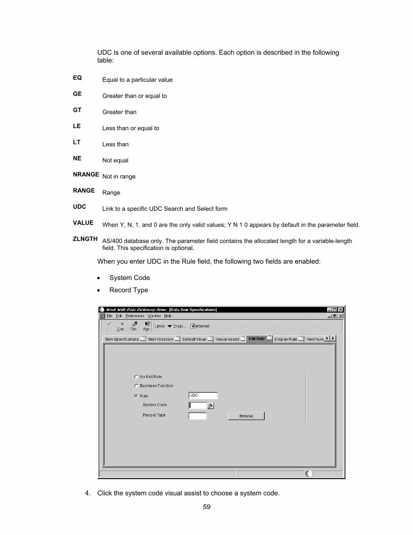
UDC is one of several available options. Each option is described in the following table:
EQ Equal to a particular value
GE Greater than or equal to
GT Greater than
LE Less than or equal to
LT Less than
NE Not equal
NRANGE Not in range
RANGE Range
UDC Link to a specific UDC Search and Select form
VALUE When Y, N, 1, and 0 are the only valid values; Y N 1 0 appears by default in the parameter field.
ZLNGTH AS/400 database only. The parameter field contains the allocated length for a variable-length field. This specification is optional.
When you enter UDC in the Rule field, the following two fields are enabled:
• System Code
• Record Type
4. Click the system code visual assist to choose a system code.
59

5. Click the Browse button to choose a record type.
Data Dictionary Naming Conventions
This chapter is devoted entirely to OneWorld data dictionary item naming conventions. Whether you are an internal J.D. Edwards developer or a developer external to J.D. Edwards you must refer to the data item naming conventions. Adhering to these conventions ensures database integrity and prevents data items from being overwritten or colliding with other data items.
If you are creating a data item for use in WorldSoftware and OneWorld, separate limitations and considerations are required that are not addressed in detail in this guide.
Attaching a Next Number Trigger
The next numbers feature controls the automatic numbering for such items as new general ledger account numbers, voucher numbers, and address numbers. It allows you to specify the numbering system code that you want to use and gives you a method of automatically incrementing numbers to reduce transpositions and keying errors.
Use a next number when you want the system to enter a default value in a numeric data item if the user does not enter a number. Next numbers are assigned from an array. The combination of system code and index defines how the next number will be assigned.
60

Next Numbers The Next Numbers table is F0002, and it has the following logic:
• 1 record per system and 10-element array
The key to the Next Numbers table (F0002) is system code. The table includes 10 columns for individual next number elements. The system uses each of these elements for a specific hard code within the applications for that system code.
For example, if you select system code 09 in the Next Numbers program, six rows are populated and four are blank. The system uses each of these coded, populated rows as hard code. The first row defines New Account ID. Within J.D. Edwards applications that create new accounts, the system retrieves the account number from system 09, row 1 of the Next Numbers table. Row 2 contains Journal Entries. In a master business function (MBF) that creates journal entry documents, the system retrieves the document number from system 09, row 2 of the Next Numbers table.
If you select system 04 in the Next Numbers program, the system uses a completely separate set of rows that have hard codes for use within system 04.
• Modulus 11 check optional
The check digits options allows you to specify whether the system adds a number to the end of each next number that it assigns.
For example, if you are using check digits and the next number is 2, the system adds a check digit such as 7, making the last two numbers 27. Check digits provide a method of randomly incrementing numbers to prevent the assignment of transposed numbers. In the following algorithm, the system would never assign next number 72 while check digits is activated.
IBM Modulus 11 Self-Check Algorithm Each position in the base number has a weight factor. Modulus 11 counts positions from the rightmost digit (not including the check digit).
The Modulus 11 weight factors are 2, 3, 4, 5, 6, 7, 2, 3, 4, 5, 6, 7, ...2, 3, 4, 5, 6, 7, 2 for positions 1, 2, .... 31, respectively.
After you set next numbers, do not change it. If you change next numbers, the following might occur:
• System performance is affected.
• Next numbers will not duplicate numbers; when it reaches the maximum, it starts over
• You cannot change position or add a new entry without programming modifications
Next numbers connects to the data dictionary. A data item in the data dictionary points to the Next Number system. You can access the Next Numbers program (P0002) from the OneWorld menu G00.
► To attach a next number trigger
1. On Data Item Specifications, click the Next Number tab.
2. On Next Number, click the following option:
• Next Number
61

3. Complete the following fields:
• System Code
• Index
Attaching a Smart Field Trigger
Smart Fields are actually data dictionary items with attached business functions. The business functions that are attached include named mappings, which simplify the process of selecting a data item with particular functionality. End users do not need to know which business function to use and what parameters to pass; instead, the user simply selects a data item that inherently has this information. Smart fields can be used in all section types in Report Design. For example, you can use smart fields to derive a column heading or an object value in a tabular section. Smart fields are always glossary group K.
► To attach a smart field trigger
1. On Data Item Specifications, click the Item Specifications tab.
2. Complete the following required fields:
• Description
• System Code
• Data Type
62
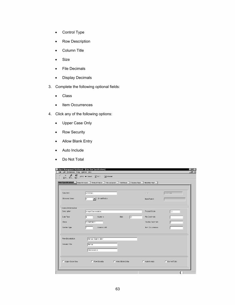
• Control Type
• Row Description
• Column Title
• Size
• File Decimals
• Display Decimals
3. Complete the following optional fields:
• Class
• Item Occurrences
4. Click any of the following options:
• Upper Case Only
• Row Security
• Allow Blank Entry
• Auto Include
• Do Not Total
63

5. From the Form menu, choose Smart Fields.
6. On Smart Field, complete the following fields:
• Business Function
Enter the business function that was created for the smart field.
• Event Name
Specify the event in which the smart field should be triggered.
• Named mapping
Enter the named mapping that is associated with the business function data structure.
On Smart Fields, you can click the Browse button to select a business function.
64

On Smart Fields, you can click the visual assist on Named Mapping to select a value.
65
Updating the Glossary
Each data item is described within the glossary. The end user of an application sees this text at runtime. Thus, it should explain how the field is used in the application. Within an application, you can access this glossary description in field-level help. You can also do the following:
• Add glossary text for new data items
• Create form-specific or system-specific glossary text
• Create glossary text for different languages
• Customize J.D. Edwards glossary text to suit your needs
66

► To update the glossary
1. On Data Item Specifications, click the Item Glossary tab.
2. Complete the following field:
Adding Glossary Text for Languages For a new or existing data dictionary item, you can add separate glossary text for different languages. For example, you can create glossary text for the base English language item and also have glossary text for French, Spanish, and German. Glossary text for languages must be added after the data dictionary item has been created.
67
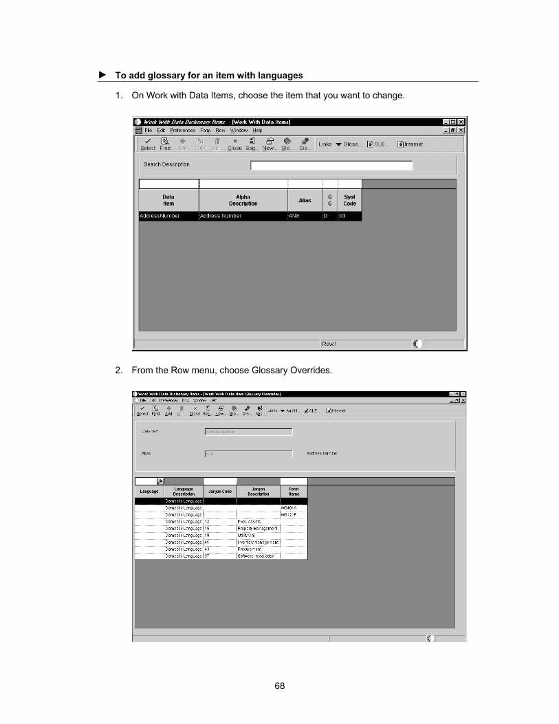
► To add glossary for an item with languages
1. On Work with Data Items, choose the item that you want to change.
2. From the Row menu, choose Glossary Overrides.
68
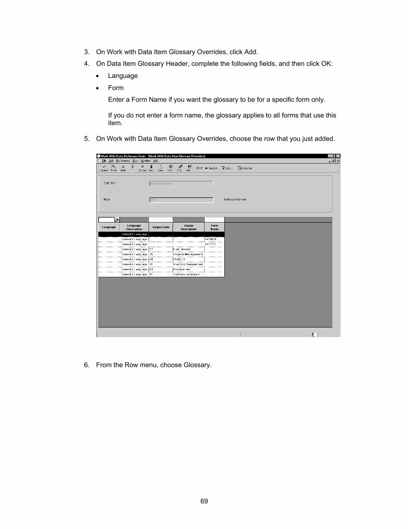
3. On Work with Data Item Glossary Overrides, click Add.
4. On Data Item Glossary Header, complete the following fields, and then click OK:
• Language
• Form
Enter a Form Name if you want the glossary to be for a specific form only.
If you do not enter a form name, the glossary applies to all forms that use this item.
5. On Work with Data Item Glossary Overrides, choose the row that you just added.
6. From the Row menu, choose Glossary.
69
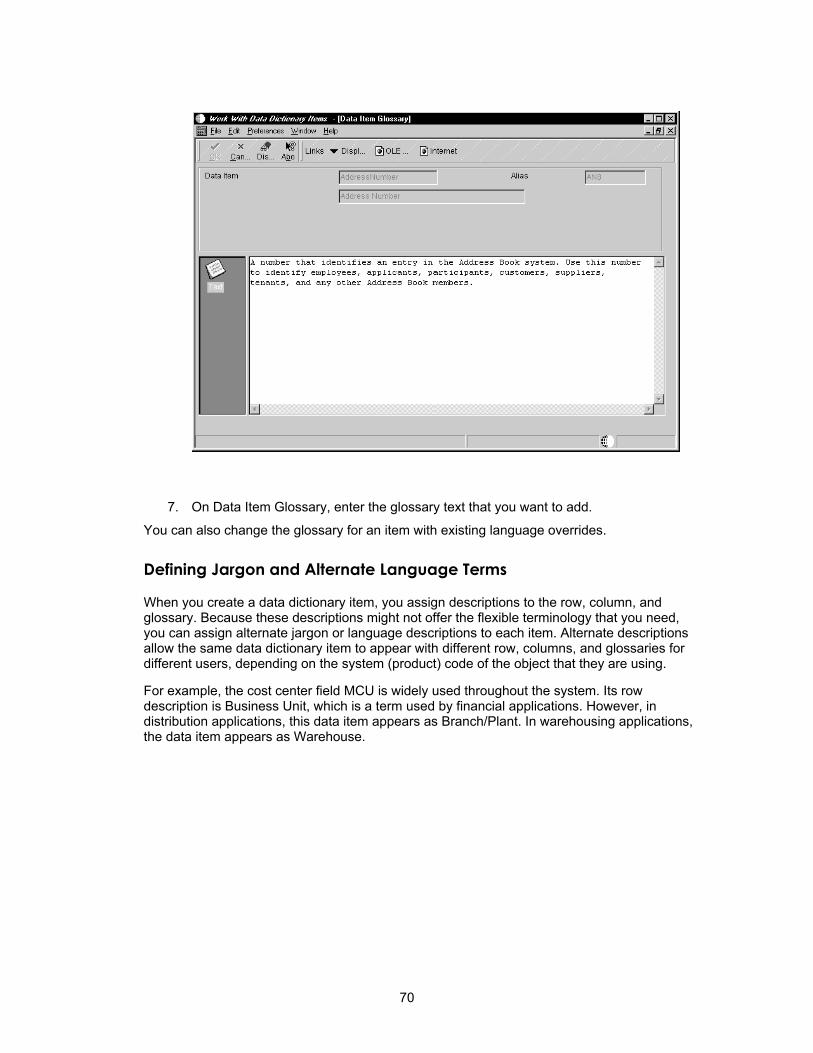
7. On Data Item Glossary, enter the glossary text that you want to add.
You can also change the glossary for an item with existing language overrides.
Defining Jargon and Alternate Language Terms
When you create a data dictionary item, you assign descriptions to the row, column, and glossary. Because these descriptions might not offer the flexible terminology that you need, you can assign alternate jargon or language descriptions to each item. Alternate descriptions allow the same data dictionary item to appear with different row, columns, and glossaries for different users, depending on the system (product) code of the object that they are using.
For example, the cost center field MCU is widely used throughout the system. Its row description is Business Unit, which is a term used by financial applications. However, in distribution applications, this data item appears as Branch/Plant. In warehousing applications, the data item appears as Warehouse.
70
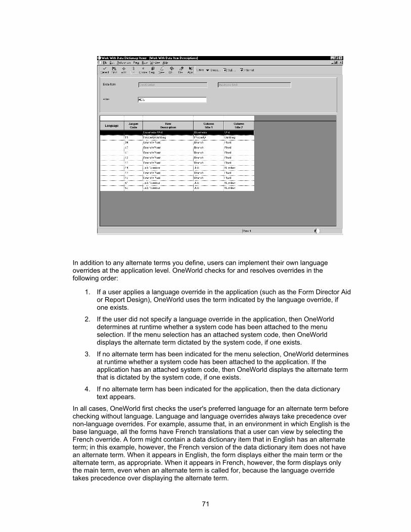
In addition to any alternate terms you define, users can implement their own language overrides at the application level. OneWorld checks for and resolves overrides in the following order:
1. If a user applies a language override in the application (such as the Form Director Aid or Report Design), OneWorld uses the term indicated by the language override, if one exists.
2. If the user did not specify a language override in the application, then OneWorld determines at runtime whether a system code has been attached to the menu selection. If the menu selection has an attached system code, then OneWorld displays the alternate term dictated by the system code, if one exists.
3. If no alternate term has been indicated for the menu selection, OneWorld determines at runtime whether a system code has been attached to the application. If the application has an attached system code, then OneWorld displays the alternate term that is dictated by the system code, if one exists.
4. If no alternate term has been indicated for the application, then the data dictionary text appears.
In all cases, OneWorld first checks the user's preferred language for an alternate term before checking without language. Language and language overrides always take precedence over non-language overrides. For example, assume that, in an environment in which English is the base language, all the forms have French translations that a user can view by selecting the French override. A form might contain a data dictionary item that in English has an alternate term; in this example, however, the French version of the data dictionary item does not have an alternate term. When it appears in English, the form displays either the main term or the alternate term, as appropriate. When it appears in French, however, the form displays only the main term, even when an alternate term is called for, because the language override takes precedence over displaying the alternate term.
71

Jargon and alternate language terms must be added after the data dictionary item has been created.
See Also Updating the Glossary for information about how to create alternate language
glossary items for a data item
► To define jargon
1. On Work with Data Dictionary Items, find the item for which you want to define jargon.
2. From the Row menu, choose Descrip. Overrides.
3. Click Add.
The Data Item Descriptions form appears.
4. On Data Item Descriptions, complete the following fields, and then click OK:
• Jargon Code
Enter or select the system code with which you want to associate the current jargon. Different system codes are associated with specific categories and applications in the system.
• Row Description
• Column Title
5. Repeat this process for each jargon term that you want to associate with the data item.
► To update a data item for languages
1. On Work with Data Dictionary Items, find the item that you want to update.
2. From the Row menu, choose Descrip. Overrides.
3. Click Add.
The Data Item Descriptions form appears.
4. Complete the following fields and click OK:
• Language
• Row Description
• Column Title
5. Repeat this process for each language that you want to associate with the data item.
You can change the row and column text for all applications (interactive or batch) that use a data item.
72

► To change row and column text for all applications
1. On Work with Data Dictionary Items, find the item that you want to update.
2. From the Row menu, choose Descrip. Overrides.
73

3. Choose a language record and modify it.
You can change the alpha description by clicking Glossary Overrides and creating a record. You then use the Glossary form to change the description.
For information about changing the row and column text for a particular application (interactive or batch) that use this data item, see the Package Management Guide.
Changes to row and column descriptions are not replicated through data replication. To deploy row and column changes to workstations, you must deliver a new full or partial package, or an update package that includes the affected applications. The new or update package deletes the existing row and columns that are stored in a cache on the workstation.
Table Design
A relational database table stores data that an application uses. You can create one or more tables for use in an application. To create a table, you select data items (the data items must exist in the data dictionary) to include in the table and assign key fields as indices for retrieving and updating data. You must define your table so that OneWorld recognizes that the table exists.
You must use Table Design to generate the table whenever want to perform the following:
• Create a new table
• Add or delete a data item
• Add or modify an index
A table stores a set of data in columns and rows. Each column is a data item. Each row is a record.
74
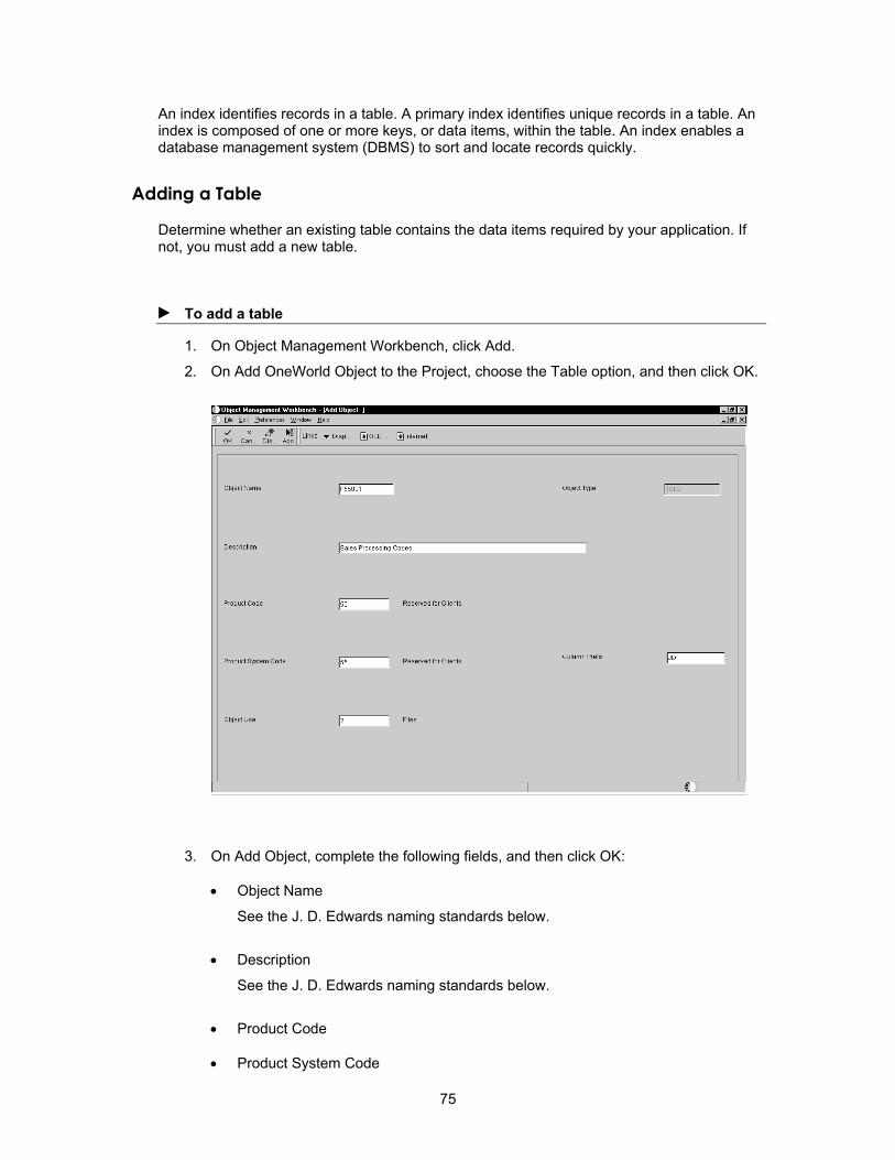
An index identifies records in a table. A primary index identifies unique records in a table. An index is composed of one or more keys, or data items, within the table. An index enables a database management system (DBMS) to sort and locate records quickly.
Adding a Table
Determine whether an existing table contains the data items required by your application. If not, you must add a new table.
► To add a table
1. On Object Management Workbench, click Add.
2. On Add OneWorld Object to the Project, choose the Table option, and then click OK.
3. On Add Object, complete the following fields, and then click OK:
• Object Name
See the J. D. Edwards naming standards below.
• Description
See the J. D. Edwards naming standards below.
• Product Code
• Product System Code
75
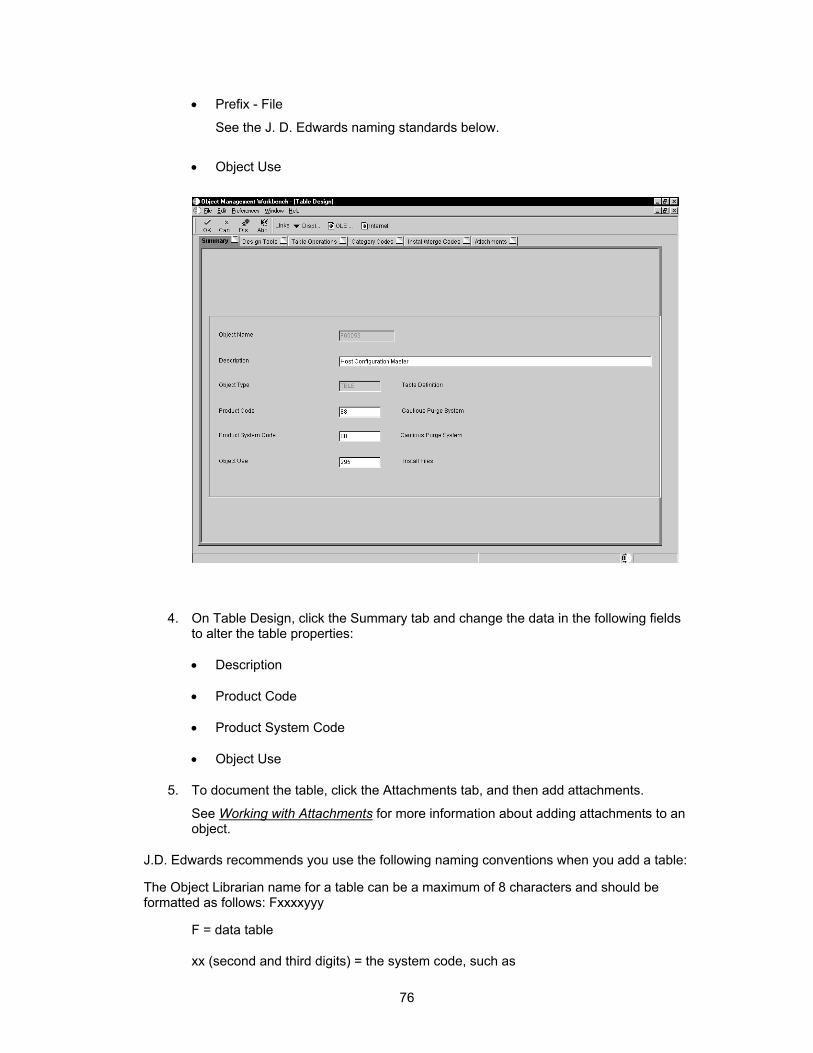
• Prefix - File
See the J. D. Edwards naming standards below.
• Object Use
4. On Table Design, click the Summary tab and change the data in the following fields to alter the table properties:
• Description
• Product Code
• Product System Code
• Object Use
5. To document the table, click the Attachments tab, and then add attachments.
See Working with Attachments for more information about adding attachments to an object.
J.D. Edwards recommends you use the following naming conventions when you add a table:
The Object Librarian name for a table can be a maximum of 8 characters and should be formatted as follows: Fxxxxyyy
F = data table
xx (second and third digits) = the system code, such as
76
00 - OneWorld Foundation environment
01 - Address Book
03 - Accounts Receivable
xx (fourth and fifth digits) = the group type, such as
01 - Master
02 - Balance
1X - Transaction
yyy (sixth through eighth digits) = object version, such as programs that perform similar functions but vary distinctly in specific processing
LA through LZ - Logical file
JA through JZ - Table join
Provide up to a 60-character description for a table.
The table description is the topic of the table. If it came from the AS/400, it should be the same name as the file it represents, such as Address Book Master (F0101) and Item Master (F4101).
The column prefix is a two-character code used to uniquely identify table columns. The first character must be numeric and the second character must be alpha-numeric.
Table Naming Conventions
J.D. Edwards recommends you use the following naming conventions when you add a table:
The Object Librarian name for a table can be a maximum of 8 characters and should be formatted as follows: Fxxxxyyy
F = data table
xx (second and third digits) = the system code, such as
00 - OneWorld Foundation environment
01 - Address Book
03 - Accounts Receivable
xx (fourth and fifth digits) = the group type, such as
01 - Master
02 - Balance
1X - Transaction
yyy (sixth through eighth digits) = object version, such as programs that perform similar functions but vary distinctly in specific processing
77

LA through LZ - Logical file
JA through JZ - Table join
Provide up to a 60-character description for a table.
The table description is the topic of the table. If it came from the AS/400, it should be the same name as the file it represents, such as Address Book Master (F0101) and Item Master (F4101).
The column prefix is a two-character code used to uniquely identify table columns.
The first character must be alphabetic. The second character can be alphanumeric. You cannot assign special characters (for example, $, #, or @).
The data item name follows the column prefix. For example, Address Number in the Address Book Master (F0101) is ABAN8. The prefix does not have to be unique in OneWorld® because the Tool Design Aid makes it unique. For example, the system references ABAN8 as F0101_ABAN8.
Indices
List the field as the index name, such as Address Number, if there is only one field in the index.
For coexistence, it is critical that OneWorld indices match logicals on the AS400. When you run the Generate Table command in Table Design, OneWorld automatically determines whether a matching file exists on the AS400. If a matching AS400 file does not exist, then OneWorld creates logical files on the AS400. If a matching AS400 file exists, OneWorld does not create any logicals on the AS400.
If an index has two fields, list them consecutively, such as Address Number, Line Number ID.
List the first two fields followed by an alpha character (A), such as Address Number, Line Number, A, if there are more than two fields in the index and the first two fields are the same as the first two fields of another index. Otherwise, list the fields followed by a (+), such as Item Number, Branch, +.
Place a comma and space ( , ) between each index field and between the last index field and the plus sign.
Do not include more than 10 fields in an index.
The total length of the index name cannot exceed 19 characters if the index has two or more fields. If you exceed 19 characters, the compiler displays the warning Re-definition is not identical.... This situation affects fetches that use the wrong index ID in business functions.
Working with Table Design
Table Design presents the following views within a single window:
• Table Columns, which displays the data items that make up your table.
• Data Dictionary Browser, which locates data items for selecting and moving to the Column view.
• Indices, which defines the unique data items for quicker sorting and updating of the table.
78
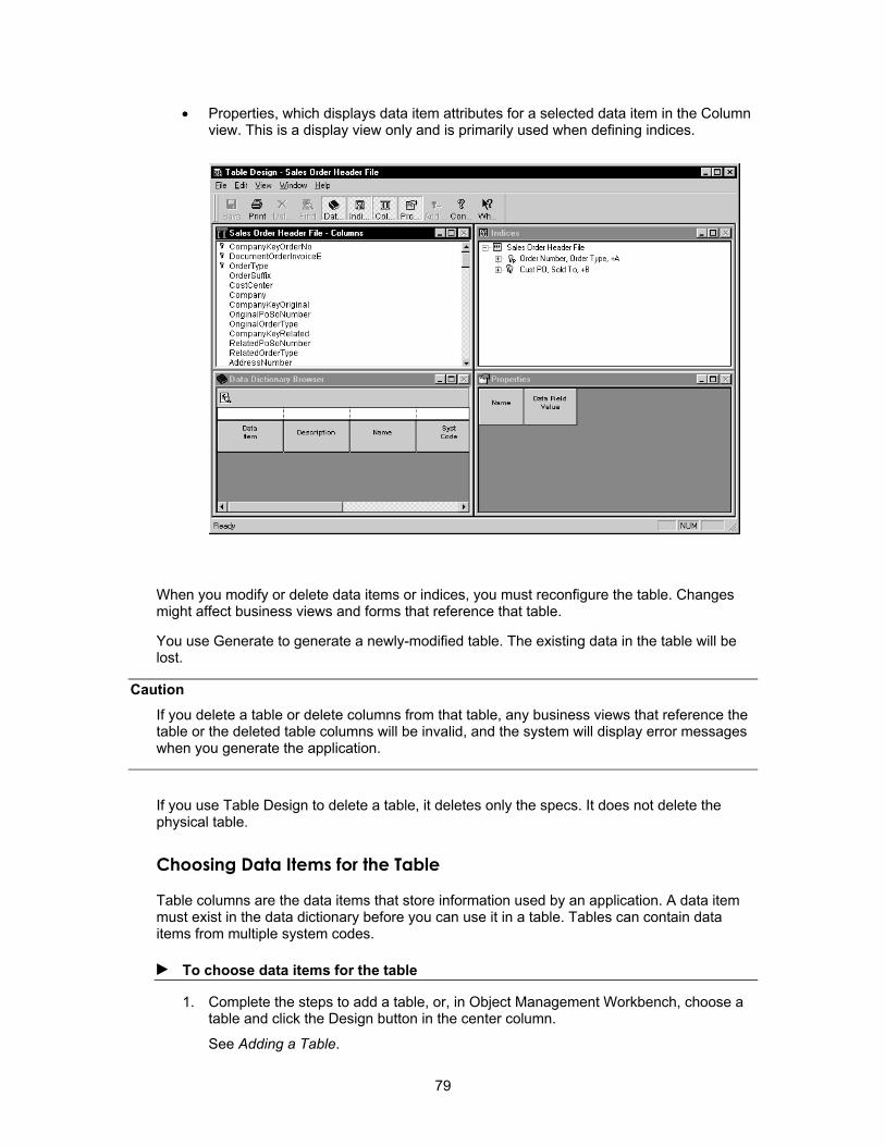
• Properties, which displays data item attributes for a selected data item in the Column view. This is a display view only and is primarily used when defining indices.
When you modify or delete data items or indices, you must reconfigure the table. Changes might affect business views and forms that reference that table.
You use Generate to generate a newly-modified table. The existing data in the table will be lost.
Caution If you delete a table or delete columns from that table, any business views that reference the table or the deleted table columns will be invalid, and the system will display error messages when you generate the application.
If you use Table Design to delete a table, it deletes only the specs. It does not delete the physical table.
Choosing Data Items for the Table
Table columns are the data items that store information used by an application. A data item must exist in the data dictionary before you can use it in a table. Tables can contain data items from multiple system codes.
► To choose data items for the table
1. Complete the steps to add a table, or, in Object Management Workbench, choose a table and click the Design button in the center column.
See Adding a Table.
79

2. On Table Design, click the Design Tools tab, and then click Start Table Design Aid.
3. In the Data Dictionary Browser view, use QBE to locate the data dictionary items that you want to include in your table.
4. To include a data item in your table, drag it from the Data Dictionary Browser view to the Table Columns view.
5. To remove a column from a table, choose it and choose Delete from the Edit menu.
Defining Indices
You use indices to find specific records and to sort records faster. Table indices are like tabs in a card file. Each index is comprised of one or more keys, which are individual data items. You use indices to access data in the most simple manner so you do not have to read the data sequentially.
OneWorld middleware generates an SQL statement that the native database understands.
A table can have multiple indices; however, every table must have only one primary, unique index. The primary, unique index is the one unique identifier for each record in the table. The database should use the index that returns the most detail. It does not always use the primary index. Additionally, you use the primary index to build business views.
See Also Performance for information about performance issues regarding indices
Business View Design for information about how business views use the primary index from a table
► To define indices
1. On Table Design, focus on the Indices form so that the Indices menu appears.
2. From the Indices menu, choose Add.
You can also drag indices from the column view into the index view.
The index description is Untitled; it is marked with a key that displays the letter P to indicate a primary index.
80

3. Double-click the index title to name the index. After you name the index, press Enter.
4. On the Table Columns view, choose one or more columns from the columns view and drag them to the index.
A unique index is marked with a single key. You can toggle the unique/not unique status of a key by clicking your right mouse button and choosing Unique from the Index menu. The Unique Primary Index cannot be changed to nonunique status.
5. Indicate the ascending or descending sort order for an index column. An arrow pointing in the upward direction indicates that the index column is sorted in ascending order.
J.D. Edwards Design Standards Use the following guidelines to name an index.
• List the field as the index name, such as Address Number, if the index contains only one field.
• For coexistence, OneWorld indices must match logicals on the AS/400. When you run the Generate Table command in Table Design, OneWorld automatically determines whether a matching AS/400 file exists. If a matching AS/400 file does not exist, then OneWorld creates logical files on the AS/400. If a matching AS/400 file exists, OneWorld does not create any logicals on the AS/400.
• If the index contains two fields, list them consecutively, such as Address Number, Line Number ID.
• List the first two fields followed by an alpha character (A), such as Address Number, Line Number, A, if the index contains more than two fields and the first
81
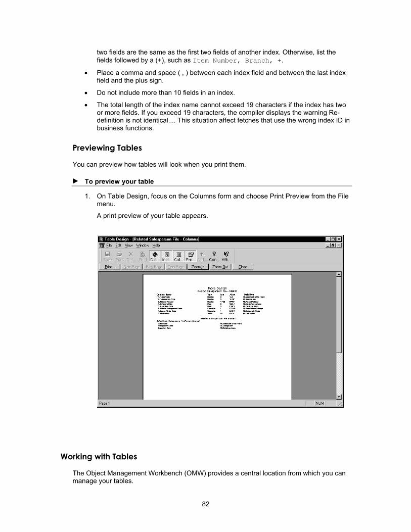
two fields are the same as the first two fields of another index. Otherwise, list the fields followed by a (+), such as Item Number, Branch, +.
• Place a comma and space ( , ) between each index field and between the last index field and the plus sign.
• Do not include more than 10 fields in an index.
• The total length of the index name cannot exceed 19 characters if the index has two or more fields. If you exceed 19 characters, the compiler displays the warning Re-definition is not identical.... This situation affect fetches that use the wrong index ID in business functions.
Previewing Tables
You can preview how tables will look when you print them.
► To preview your table
1. On Table Design, focus on the Columns form and choose Print Preview from the File menu.
A print preview of your table appears.
Working with Tables
The Object Management Workbench (OMW) provides a central location from which you can manage your tables.
82

Generating Tables
After you have selected data items and assigned indices for your table, you are ready to configure the table for a specific data source. If you have not established an index, your generation will fail.
You must generate a table to create the physical table. You cannot add to or update the table until it is generated. Table generation also creates a .h file that is used for compiling in business functions and table event rules.
The OMW calls the Object Configuration Manager application (P986110) to configure tables. You can configure the table within any existing data source. If you do not indicate a data source, OneWorld automatically configures the table for the default map. You can change the path code to generate the table in a different location. This actually does a drop statement similar to the remove table, and then the table is recreated. If you regenerate the current table, the data in it will be lost.
You must regenerate a table after you modify it, such as when you delete or add data items. To ensure that data is not lost, you must export your data, generate the table, and copy the data back into the table.
► To generate tables
1. On Table Design, click the Table Operations tab, and then click Generate Table.
2. On Generate Table, complete the following fields, and then click OK:
• Data Source
• Password
A message appears indicating whether the generation was successful.
Generating Indexes
If you create additional indices or modify existing ones, you must regenerate them. This modifies the .h file, but you will not lose existing data, as you do when you regenerate the entire table.
► To generate indexes
1. On Table Design, click the Table Operations tab, and then click Generate Indexes.
2. On Generate Indexes, complete the following fields, and then click OK:
• Data Source
• Password
Generating Header Files
Occasionally, a table might have no header files. Use this process to generate header files without having to generate the entire table.
83

► To generate header files
1. On Table Design, click the Design Tools tab, and then click Generate Header File.
The system generates the header file.
Copying Tables
You can copy tables from one data source to another. This operation does not copy table specifications. You can also use table conversion to copy tables from one data source to another.
See Also Table Conversion Guide for more information about using the Table Conversion tool
to copy tables
► To copy tables
1. On Table Design, click the Table Operations tab, and then click Copy Table.
2. Complete the following fields, and then click OK:
• Data Source
• Data Source
• Object Owner ID
• Password
Removing Tables from the Database
To completely remove a table from the system, you must use the OMW function, Remove Table from Database. If you use Table Design to delete a table, it deletes only the specifications. Table Design cannot physically delete a table.
► To remove tables from the database
1. On Table Design, click the Table Operations tab, and then click Remove Table from Database.
2. On Remove Table, complete the following fields, and then click OK:
• Data Source
• Password
Viewing the Data in Tables
If you want to view the data in tables in different databases, you can use the Universal Table Browser. This tool lets you verify the existence of data in a table, as well as determine the
84

structure of the table. The Universal Table Browser uses JDEBASE APIs to retrieve data from the database, making it independent of the database that you access.
Note You cannot use OneWorld security to directly secure users from the Universal Table Browser because it is a Windows executable application, not a OneWorld-generated application. However, you can place form security on the Table and Data Source Selection form (W98TAMC). This secures the Universal Table Browser because the Windows executable cannot function without this OneWorld form. All column and row security that you set up through Security Workbench applies to the Universal Table Browser.
► To view the data in tables
From Cross Application Development Tools (GH902), choose Universal Table Browser.
1. On Universal Table Browser, choose Open Table from the File menu.
85
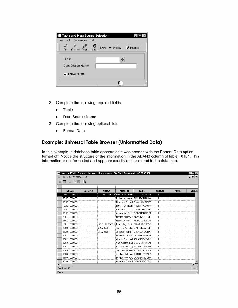
2. Complete the following required fields:
• Table
• Data Source Name
3. Complete the following optional field:
• Format Data
Example: Universal Table Browser (Unformatted Data)
In this example, a database table appears as it was opened with the Format Data option turned off. Notice the structure of the information in the ABAN8 column of table F0101. This information is not formatted and appears exactly as it is stored in the database.
86

Example: Universal Table Browser (Formatted Data)
In this example, a database table appears as it was opened with the Format Data option turned on. Notice that the structure of the information in the ABAN8 column of table F0101 is formatted using the data dictionary specifications.
Example: Column Properties
In this example, the column properties appear for the OneWorld data dictionary item USEQ. The SQL database name for this OneWorld item is DTUSEQ.
87
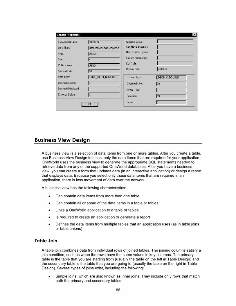
Business View Design
A business view is a selection of data items from one or more tables. After you create a table, use Business View Design to select only the data items that are required for your application. OneWorld uses the business view to generate the appropriate SQL statements needed to retrieve data from any of the supported OneWorld databases. After you have a business view, you can create a form that updates data (in an interactive application) or design a report that displays data. Because you select only those data items that are required in an application, there is less movement of data over the network.
A business view has the following characteristics:
• Can contain data items from more than one table
• Can contain all or some of the data items in a table or tables
• Links a OneWorld application to a table or tables
• Is required to create an application or generate a report
• Defines the data items from multiple tables that an application uses (as in table joins or table unions)
Table Join
A table join combines data from individual rows of joined tables. The joining columns satisfy a join condition, such as when the rows have the same values in key columns. The primary table is the table that you are starting from (usually the table on the left in Table Design) and the secondary table is the table that you are going to (usually the table on the right in Table Design). Several types of joins exist, including the following:
• Simple joins, which are also known as inner joins. They include only rows that match both the primary and secondary tables.
88

• Right outer joins, which include rows common to both the primary and secondary tables, and unmatched rows from the secondary table.
• Left outer joins, which include rows common to both the primary and secondary tables, and unmatched rows from the primary table.
89

Table Union
A table union appends entire tables. It first presents to the application selected rows from the primary table, then rows with corresponding columns from the secondary table. If the rows from the two tables contain identical data, then only one of the records is retrieved in the union.
Unions include rows from the primary table and corresponding columns from the secondary table.
90
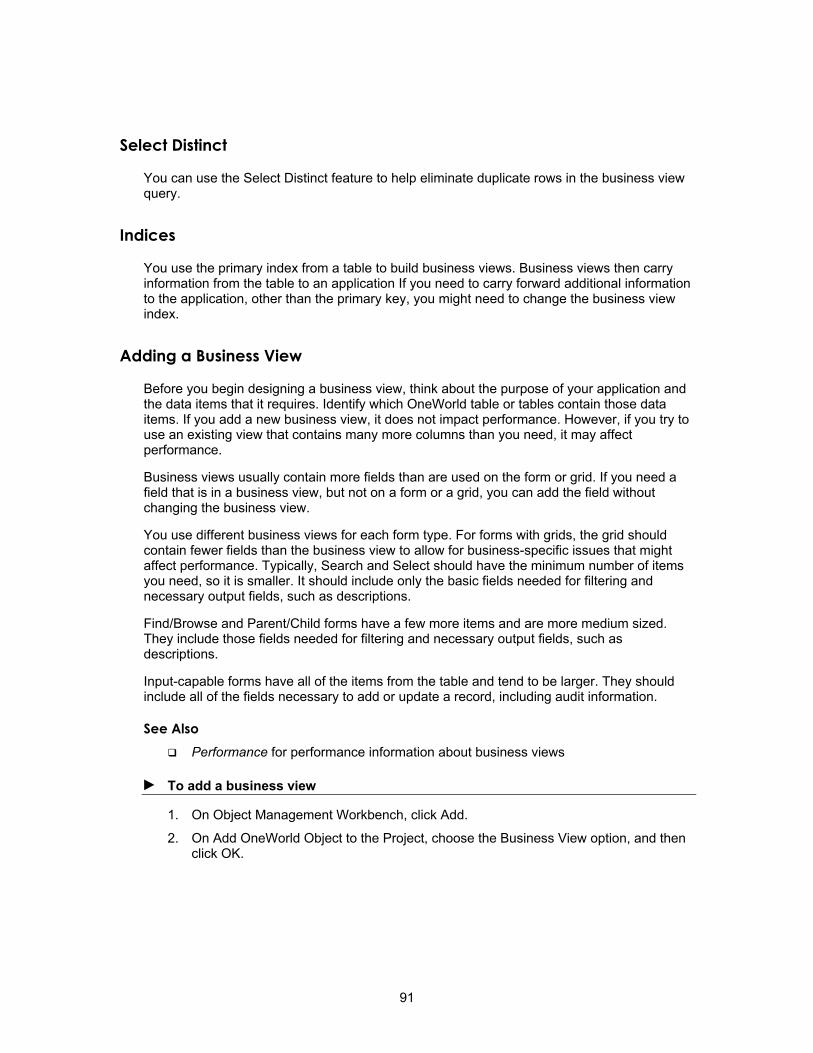
Select Distinct
You can use the Select Distinct feature to help eliminate duplicate rows in the business view query.
Indices
You use the primary index from a table to build business views. Business views then carry information from the table to an application If you need to carry forward additional information to the application, other than the primary key, you might need to change the business view index.
Adding a Business View
Before you begin designing a business view, think about the purpose of your application and the data items that it requires. Identify which OneWorld table or tables contain those data items. If you add a new business view, it does not impact performance. However, if you try to use an existing view that contains many more columns than you need, it may affect performance.
Business views usually contain more fields than are used on the form or grid. If you need a field that is in a business view, but not on a form or a grid, you can add the field without changing the business view.
You use different business views for each form type. For forms with grids, the grid should contain fewer fields than the business view to allow for business-specific issues that might affect performance. Typically, Search and Select should have the minimum number of items you need, so it is smaller. It should include only the basic fields needed for filtering and necessary output fields, such as descriptions.
Find/Browse and Parent/Child forms have a few more items and are more medium sized. They include those fields needed for filtering and necessary output fields, such as descriptions.
Input-capable forms have all of the items from the table and tend to be larger. They should include all of the fields necessary to add or update a record, including audit information.
See Also Performance for performance information about business views
► To add a business view
1. On Object Management Workbench, click Add.
2. On Add OneWorld Object to the Project, choose the Business View option, and then click OK.
91

3. On Add Object, complete the following fields and click OK:
• Object Name
See J. D. Edwards Naming Standards for guidelines.
• Description
• Product Code
• Product System Code
• Object Use
J. D. Edwards Naming Standards J.D. Edwards recommends that you use the following guidelines when you add a business view.
The Object Librarian name for a business view can be a maximum of 10 characters and should be formatted as follows: VzzzzzzzzA, where:
V = Business view.
zzzzzzzz = The characters that represent the primary table.
A = A letter that designates the view. For example, V0101A is the first view of the table F0101, and V0101B is the second view of the same table.
92

External Developer Considerations External development refers to creation of applications by developers who do not work for J.D. Edwards, such as Partners in Development and J.D. Edwards consultants who create custom applications for specific clients. To prevent interference between J.D. Edwards and non-J.D. Edwards objects, you must use caution when naming a business view. When you create a new business view for a standard J.D. Edwards table, format the business view name as follows: Vssss9999, where
V = Business view.
ssss = The system code for the enterprise.
9999 = A unique next number or character pattern within the enterprise
Provide up to a 60-character description for a business view. It should reflect the application description followed by the form type, such as Item Master Browse and Item Master Revisions.
Primary unique key fields should remain in the business view. Do not reorganize the primary unique key fields.
Note One business view for each table should include all columns. Use this business view for the level 01 section in all reports upon which the file is based. Also, only one business view is allowed for each form type, except for a header/detail form. In this instance, two business views may be selected, one for the header portion of the form and one for the detail portion of the form.
Joined Views
To format the name for a joined view, use the names of the two tables being joined, separated by a forward slash. Place the primary table first.
For example, where F4101 is the primary table in the join view between F4101 and F4102, use the following naming standard: F4101/F4102.
Working with Business View Design
The Business View Design tool displays the following views:
• Table Joins, which defines the tables over which you create the business view.
• Available Tables, which locates tables for selecting and moving to the Table Joins view.
• Selected Columns, which lists the data items from your table that are included in your business view.
• Properties
93
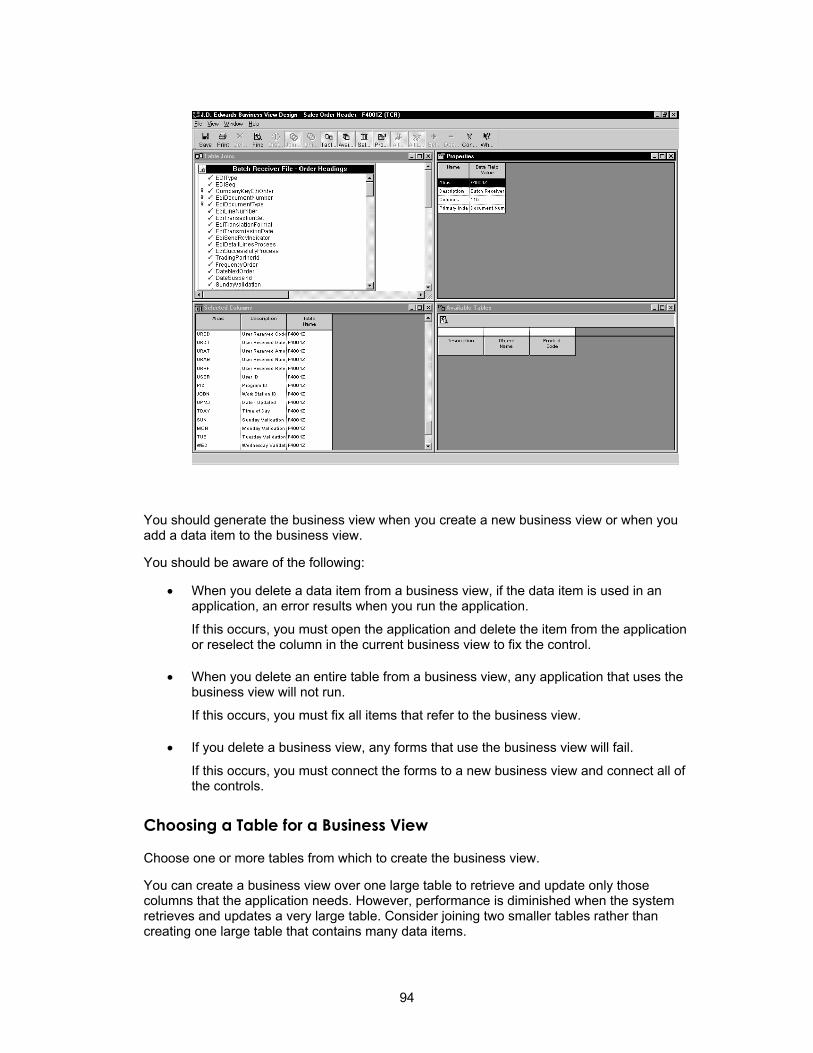
You should generate the business view when you create a new business view or when you add a data item to the business view.
You should be aware of the following:
• When you delete a data item from a business view, if the data item is used in an application, an error results when you run the application.
If this occurs, you must open the application and delete the item from the application or reselect the column in the current business view to fix the control.
• When you delete an entire table from a business view, any application that uses the business view will not run.
If this occurs, you must fix all items that refer to the business view.
• If you delete a business view, any forms that use the business view will fail.
If this occurs, you must connect the forms to a new business view and connect all of the controls.
Choosing a Table for a Business View
Choose one or more tables from which to create the business view.
You can create a business view over one large table to retrieve and update only those columns that the application needs. However, performance is diminished when the system retrieves and updates a very large table. Consider joining two smaller tables rather than creating one large table that contains many data items.
94

► To choose a table for a business view
1. On Object Management Workbench, create a new business view or choose an existing business view, and then click the Design button in the center column.
2. Click the Design Tools tab, and then click Start the Business View Design Aid.
3. On the Available Tables view of Business View Design, locate the table for the business view using the query-by-example line. You can search by description, name, and system code.
4. Choose one or more tables and drag them to the Table Joins view. The view is called Table Join regardless of whether you are joining multiple tables.
The Table Joins view displays selected tables, along with the columns that comprise each. Key symbols appear next to columns that are index keys in the table. The primary table supplies the key to the business view. This is where an application begins a search.
Note To ensure maximum performance in your application, OneWorld limits the number of tables to five if all joins are simple joins, or to three tables if any of the joins is an outer join or if there is a union.
95

5. Designate a primary table by double-clicking the title bar of the desired table (optional).
If the business view contains multiple tables, the first table added is automatically designated as the primary table. A crown symbol appears in the upper left corner of the window to indicate the primary table. If a business view contains only one table, that table is automatically the primary table.
6. To delete a table from a business view, choose it and choose Delete from the Table menu, or click the right mouse button and choose the Delete menu item.
Choosing Data Items for a Business View
After you choose one or more tables for the business view and indicate the primary table, you must choose the data items to include in the business view. All data items in the primary table, along with any tables to which the primary table is joined, are available for the business view.
Choose the data items that you want to use in an interactive application or batch job. When you create an application, you do not have to use every item in the business view.
► To choose data items for a business view
1. On the Table Joins view of Business View Design, double-click the data items to include in the business view.
Selected data items appear highlighted in the Table Joins window. As you select each item, it is added to the Selected Columns window.
Do not select more than 256 columns for your business view. An application that uses a business view that contains more than 256 columns will fail at runtime.
96
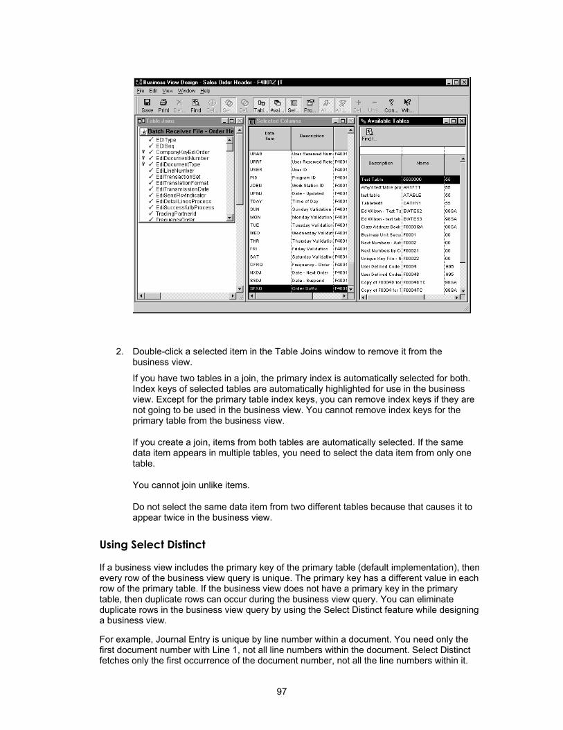
2. Double-click a selected item in the Table Joins window to remove it from the business view.
If you have two tables in a join, the primary index is automatically selected for both. Index keys of selected tables are automatically highlighted for use in the business view. Except for the primary table index keys, you can remove index keys if they are not going to be used in the business view. You cannot remove index keys for the primary table from the business view.
If you create a join, items from both tables are automatically selected. If the same data item appears in multiple tables, you need to select the data item from only one table.
You cannot join unlike items.
Do not select the same data item from two different tables because that causes it to appear twice in the business view.
Using Select Distinct
If a business view includes the primary key of the primary table (default implementation), then every row of the business view query is unique. The primary key has a different value in each row of the primary table. If the business view does not have a primary key in the primary table, then duplicate rows can occur during the business view query. You can eliminate duplicate rows in the business view query by using the Select Distinct feature while designing a business view.
For example, Journal Entry is unique by line number within a document. You need only the first document number with Line 1, not all line numbers within the document. Select Distinct fetches only the first occurrence of the document number, not all the line numbers within it.
97

Any business view with a primary table that contains one or more of the following columns, which are used for currency support or security features, might cause the Select Distinct feature to output duplicate values:
CO Company
CRCD Currency Code - From
CRDC Currency Code - To
CRCX Currency Code - Denominated In
CRCA Currency Code - A/B Amounts
LT Ledger Type
AID Account ID
MCU Business Unit
KCOO Order Company (Company Code)
EMCU Business Unit Header
MMCU Branch
AN8 Address Number
► To use select distinct
1. On Business View Design Aid, choose Distinct from the File menu.
2. Choose the primary table of your view.
3. From the Table menu, choose Change Index to change the index of the primary table to a nonunique index.
Example: Select Distinct This example illustrates Select Distinct. The business view used for this example, V98EVDTL, uses the primary index of the primary table by default. In this example, it is the Event Detail File (F98EVDTL). The primary index of a OneWorld table must be unique. Because of this, the system does not return duplicate values when the business view query is generated. Business View Design Aid also allows you to use any other index of the primary table when you process the business view.
Choose the primary table in Business View Design Aid. From the Table menu, choose Change Index to change the primary table index. Change Index is available only for the primary table.
98
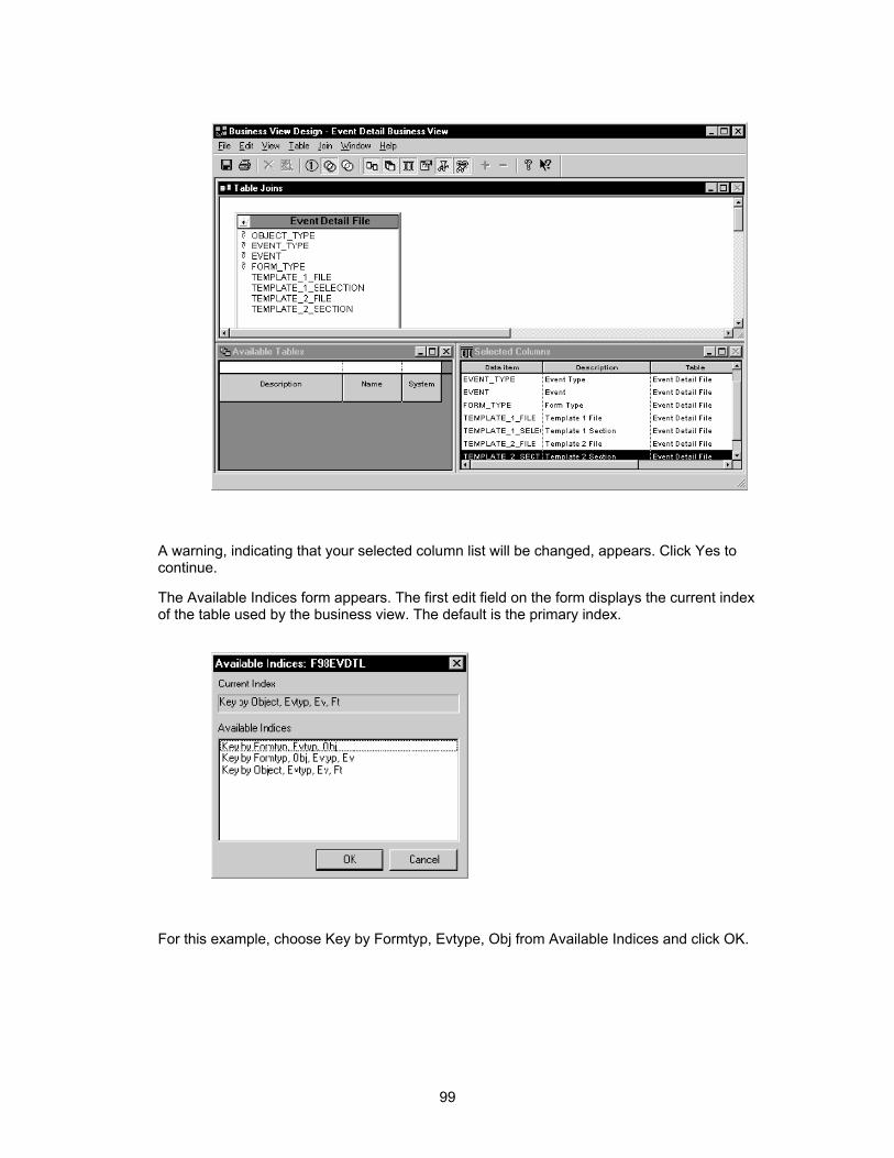
A warning, indicating that your selected column list will be changed, appears. Click Yes to continue.
The Available Indices form appears. The first edit field on the form displays the current index of the table used by the business view. The default is the primary index.
For this example, choose Key by Formtyp, Evtype, Obj from Available Indices and click OK.
99

The Table Joins list and Selected Columns list change to reflect the keys of the new index.
Save the changes and exit Business View Design Aid.
Now, if you run an application that uses the V98EVDTL business view, with Select Distinct off, and the changed business view index, Key by Formtyp, Evtyp, Obj, the generated SQL statement is:
SELECT EDOBJTYPE, EDEVTYPE, EDFORMTYPE FROM PVC. F98EVDTL
Using this example, you might now have 281 rows of data from table F98EVDTL.
Next, you reopen the V98EVDTL business view. Choose Select Distinct from the File menu. Choose Change Index to reselect the Key by Formtyp, Evtyp, Obj index from Available Indices and click OK. Save the business view and exit Business View Design Aid.
Now you might need to exit and restart OneWorld. OneWorld caches the business view in memory, so even though you have changed the business view, the previous cached business view will run until it is cleared.
When you generate and rerun the same application using the V98EVDTL business view that you just completed (with Select Distinct on and the changed business view index Key by Formtyp, Evtyp, Obj), the generated SQL statement is:
SELECT DISTINCT EDOBJTYPE, EDEVTYPE, EDFORMTYPE FROM PVC. F98EVDTL
Using this example, you might now have 53 rows of data from table the Event Detail File (F98EVDTL).
Creating a Table Join
Create table joins to access multiple tables in a single application.
100

You typically use joins for non-input-capable forms, such as Find/Browse forms, and reports. You do not usually use them for forms that update and add to the database because the relationship between the records must be precise. Use joins for input capable forms when the relationship between two tables is simple. Joins are faster than using individual fetches to retrieve data.
If a business view uses multiple tables, link them by establishing joins between columns in those tables. The links indicate how rows between a table correspond to rows in another table.
Data item attributes are defined in the data dictionary. Use the Properties window to view attributes for a column when determining whether you can use it in a join. The highlighted data item in the Selected Columns window displays the properties of that data item in the Properties window.
Review each table and decide how the data in each table is related to the data in other tables for your application or report. You might need to add columns, build indexes, or even create new tables. If you build new indexes, consider your needs carefully before you do so.
► To create a table join
1. Click and draw a line that links a column in the primary table to a column in a related table.
You can create table joins only between like columns. The name of the columns can be different, but the attributes for Data Type and Decimals must be identical. To determine whether data items are candidates for a join, view the data item attributes that appear in the Hover Hints for each data item.
2. To delete a join, choose it and then choose Delete from the Join menu; alternatively, click the right mouse button and then choose Delete from the pop-up menu.
101
3. From the Join menu, choose Types and then choose one of the following join types:
• Simple
• Left Outer
• Right Outer
The default join type is simple.
4. From the Join menu, choose Operators and choose one of the following operators:
• Equal (=)
• Less than (<)
• Greater than (>)
• Less or equal (< =)
• Greater or equal (> =)
The default operator is equal.
5. Click the Selected Columns view to sequence the columns.
Creating a Table Union
Unions are used to pull rows from tables that have the same structure. Unions pull rows that exist in either table.
► To create a table union
1. On Business View Design, from the Table menu, select Unions.
Alternatively, use the appropriate icon on the toolbar.
The view indicates Table Joins.
2. Choose the tables that you want to unite.
102

Data Structures
Data structures are a key element of any programming language or environment. A data structure is a list of parameters that passes data between applications and tables or forms. OneWorld uses data structures in the following instances:
• The system generates a data structure.
• You create a data structure.
System-Generated Data Structures
There are two types of system generated data structures:
• Form
• Report
Form Data Structures Each form with an attached business view has a default data structure. Maintain the data structure using the Form/Data Structure menu option in Forms Design. This data structure receives parameters from or sends parameters to other forms during Form Interconnects.
Report Data Structures A batch application with an attached business view can receive parameters from or send parameters to a data structure. Create and maintain the data structure from the Report/Data
103

Structure menu option in Report Design. Unlike a form data structure, this data structure is not automatically populated with data items.
User Generated Data Structures
You can create three types of data structures.
Media Object Data Structures To enable an application for media objects, you must create a data structure to pass arguments from the application table to the media object table. To work with a data structure for media objects, create a GT object type, or select an existing one to modify in Object Librarian.
Processing Options Data Structures You use processing options to create an input property sheet. You use a parameter list to pass processing options to an application. You can create a processing option data structure template or modify an existing template in Object Librarian.
Business Function Data Structures Any business function, whether it uses C or Business Function Event Rules as its source language, must have a defined data structure to send or receive parameters to or from applications. You can create a DSTR object type, or select an existing object type to work with in Object Librarian.
You can also create data structures for text substitution messages (see Messaging for more information).
You can attach notes, such as an explanation of use, to any data structure or data item within the structure.
Working with Interconnection Data Structures
The Form Design or Report Design tool, not Object Librarian, maintains interconnection data structures. The data structure enables an application or report to pass values between interconnection forms or sections.
For interactive applications, the default data structure contains only the keys from the business view selected for a form. If you want to pass a value for a data item that is not in the default data structure, you must add the data item to the data structure.
A default data structure is created at the report level for a report with an attached business view. The default data structure is empty. If you add data items to the data structure, the structure is maintained by Report Design, as is the report.
Changing Form Data Structures
You create the default data structure by using keys from the business view selected for the form. You can access the form data structure from Forms Design. From the Form menu, choose Data Structure to display the Form Data Structures form.
The items in the existing data structure appear in the Structure Members list. Two tabs appear for modifying the data structure. The Available Objects tab lists data items in the attached business view. If you want to add an item to the data structure that is not in the
104

Available Objects list, then you can select it from the Dictionary Items list. The Dictionary Items tab accesses items from the Data Dictionary.
► To change form data structures
1. On Form Design Aid, focus on the form with the data structure that you want to modify, and then select Data Structures from the Form menu.
The Form Data Structure form appears.
2. To add an object from the attached business view or grid column, click the Available Objects tab, and then drag the object into Structure Members on the left side of the form.
3. To add a specific data dictionary item, perform these steps:
• First, click the Dictionary Items tab.
• Second, enter data to search for a data dictionary item in the QBE row, and then click Find.
• Third, drag the desired data dictionary item into Structure Members on the left of the form.
4. To remove an object from the data structure, select the item in Structure Members, and then click Delete.
5. Click OK.
Changing Report Data Structures
The system creates an empty default data structure for any report section with an attached business view. This data structure receives values from another report in a report interconnection. If a required item is not in the existing data structure, you can select it from the data dictionary and include it in the Structure Members list. To modify a report data structure, use Report Design and follow the steps for changing a form data structure.
105

Example: Changing Interconnection Data Structures
The following example describes a situation in which you might want to change an interconnect data structure. Suppose that you create two Fix/Inspect forms that use the same business view. The second form shows more detail, such as additional columns from the same record. If you do not want to refetch the record in the second form, you should change the data structure for the second form.
The data structure for the second form should contain all the information (fields on the form) and data items in the data structure, in addition to the keys in the business view. In this case, you should set the Form Options to No fetch on form business view for that form. This also applies if you are not updating the record with new information on the second form, but you are passing that information back to the first form and letting the first form update the database. In this case, you should set the form options for updating the database to No Update on Form Business View.
Depending on your configuration, you might want to fetch the entire record once in the first form and pass it to the second form, or let the second form refetch the record. In this case, you will have two separate business views, with different columns from the same record. If the second form is a form that will not be accessed often, do not fetch the fields in the business view of the first form. For the first form, use a business view that has only the columns needed for the first form. If you fetch all columns needed for both forms, you perform only one Select from the database and all the data is passed over the network once, instead of having two separate Select statements generated by two different business views traversing the network. If hardware or memory for the workstation is not a problem, then fetch all columns for that record for both forms and let that information reside in the workstation's memory.
Displaying Type Definitions
You can display the typedef for a data structure. The type definition is stored in the clipboard. You can paste it into another application, such a word processing application, to save or display the definition.
106

Creating a Data Structure
A data structure object is required to create a business function. A data structure is used to pass data between an application and a business function. OneWorld provides the ability to create an encapsulated data structure object.
You can create several types of data structures that are maintained independently as objects in Object Librarian.
Refer to the Development Standards Application Design Guide for J.D. Edwards naming conventions.
Creating a Media Object Data Structure
A special data structure object is required to work with media objects. The F00165 table contains information used to determine how to access specific media object attachments. This information is stored in the Object Name and Media Object Key (GDTXKY) fields. For example, in the Sales Order application, GDTXKY stores the key for each sales order entered. The F00165 table contains the following:
• Object Name, such as GT4201A
• GDTXKY (Key), such as sales order number|order type|company
• GDTXVC (Media Object Attachment)
The media object key contains the actual key to the location in which a specific record in the application is stored. This key typically is the same as the keys to the table that is used by the
107
grid or form. The media object key must have a unique value for each media object attachment so that the system will know which attachment to retrieve.
► To create a media object data structure
1. On Object Management Workbench, click Add.
2. On Add OneWorld Object to the Project, choose the Media Object Data Structure option, and then click OK.
The Add Object form appears.
3. On Add Object, complete the following fields and click OK:
• Object Name
The J.D. Edwards standard format for naming a media object data structure is GtxxxxyyA, where:
GT = Media object
xxxx = The table name, excluding the letter F
yy = A next number
A = A letter that differentiates multiple media objects, if the table has multiple media objects.
• Description
Provide up to a 60-character description that reflects the subject of the media object.
• Product Code
• Product System Code
• Object Use
4. On Data Structure Design, click the Design Tools tab, and then click Data Structure Design.
108
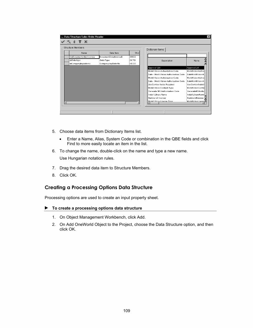
5. Choose data items from Dictionary Items list.
• Enter a Name, Alias, System Code or combination in the QBE fields and click Find to more easily locate an item in the list.
6. To change the name, double-click on the name and type a new name.
Use Hungarian notation rules.
7. Drag the desired data item to Structure Members.
8. Click OK.
Creating a Processing Options Data Structure
Processing options are used to create an input property sheet.
► To create a processing options data structure
1. On Object Management Workbench, click Add.
2. On Add OneWorld Object to the Project, choose the Data Structure option, and then click OK.
109

3. On Add Object, complete the following fields:
• Object Name
The J.D. Edwards naming convention for processing option data structures is Txxxxyyyy where:
T = Processing option data structure
xxxxyyyy = The program number for the application or report
• Description
• Product Code
• Product System Code
• Object Use
4. Choose the Processing Option Template option, and then click OK.
Creating a Business Function Data Structure
Business function data structures are used by C business functions and business function event rules to pass data between the business functions or application event rules.
► To create a business function data structure
1. On Object Management Workbench, click Add.
110

2. On Add OneWorld Object to the Project, choose the Data Structure option, and then click OK.
3. On Add Object, complete the following fields:
• Object Name
The J.D. Edwards naming convention for business function data structures is DxxxxyyyyA where:
D = Data structure
xxxx = The system code
yyyy = A next number
A = A multiple data structure differentiator (A, B, C, and so forth), used when a function has more than one data structure
• Description
• Product Code
• Product System Code
• Object Use
4. Choose the Regular Data Structure option, and then click OK.
111

Defining a Data Structure
After you create a data structure, you must define the data objects to include in the data structure. You can modify existing data structures by adding new data objects to it or deleting data objects from it.
See Also See Processing Options for information about working with processing options and
their data structures and templates.
Designing a Data Structure
After creating a data structure with the OMW, use the following process to define how it will function. The type definition is stored in the clipboard. You can paste it into another application, such a word processing application, to save or display the definition.
► To design a data structure
1. On Object Management Workbench, check out the data structure with which you want to work.
2. Select the data structure, and then click the design button in the center column.
3. On Data Structure Design, click the Design Tools tab, and then click Data Structure Design.
4. To add a data dictionary item to the data structure, complete the following steps:
• Enter data to search for a data dictionary item in the QBE row, and then click find.
• Drag the desired data dictionary item into Structure Members on the left of the form.
• To change the name, double-click the name, and enter a new name. Use Hungarian notation rules.
112

If you are unsure about which data dictionary item you want, click Data Dictionary to search for data dictionary items and then view details about the data items that you select.
You can view detailed information about a data item in the data structure by selecting it and then clicking Data Dictionary Detail.
5. You can indicate the required status by leaving the required field blank or choosing one of the following:
• An X to indicate that the field is optional.
• A checkmark to indicate that the field is required.
6. Choose a direction for the data flow by clicking the arrow until it changes to the appropriate direction and type.
7. To remove an object from the data structure, select the item in Structure Members and then click Delete.
8. To define attachments for the data structure, click Data Structure Attachments.
9. To define attachments for a data structure item, click Data Structure Item Attachments.
10. To launch the Cross Reference utility, click Cross Reference.
11. When you are finished, click OK.
Creating a Type Definition
The type definition is stored in the clipboard. You can paste it into another application, such a word processing application, to save or display the definition. You create a type definition after you create a data structure.
► To create a type definition
1. On Data Structure Design, click the Design Tools tab.
2. Click Create a type definition.
113

Cross Reference Facility
You can use the Cross Reference Facility to determine information about where specific kinds of objects are used and how they are used. You can also view relationships between objects and their components. For example, you can:
• Identify each instance in which a business function is used
• View a list of forms in an application
• Display all fields within a business view or form interconnection
• Cross-reference all applications where a specific field, event rule, or control is used
You can rebuild cross-reference relationships when you change something.
Searching for Objects
You can search for objects by search type and object name.
► To search for objects
1. From the Cross Application Development Tools menu (GH902), choose Cross Reference.
114

2. Click one of the following tabs:
• Data Items
• Interactive Applications
• Batch Applications (the batch application object type in Cross Reference is UBE)
• Business Functions
• Business Views
• Data Structures
• Tables
• Forms
Searching for Data Items
You can determine where data items are used. You can search for the following:
• Forms that use a data item
• UBEs that use a data item
• UBE event rules that use a data item as a variable
• Applications that use a data item as a variable
• Named event rules that use a data item as a variable
• Functions called by smart field data items
• Edit rule functions called by a data item
115

• Display rule functions called by a data item
• Search forms used by data items
• Processing options that use a data item
• Generic text data structures that use a data item
• Business function data structures that use a data item
• All data structures that use a data item
• Tables that use a data item
• Indices that use a data item
• Business views that use a data item
• Table event rules that use a data item
Searching for Interactive Applications
You can locate information about interactive applications. You can search for the following:
• Applications that call an application
• Applications that call a business function
• Data structures that are used by an application
• Tables that are used by an application
• Forms for an application
116

• Data items for an application
• Processing options for an application
• Business views for an application
• Data items that are used as variables in an application
Searching for Batch Applications
You can locate information about batch applications and how they are used. You can search for the following:
• UBEs that call a business function
• Tables that are used by a UBE
• Data structures that are used by a UBE
• UBEs that are called by a UBE
• UBEs that call a UBE
• Processing options for a UBE
• Business views for a UBE
• Data items that are used by a UBE
• Data items that are used as variables in a UBE
117
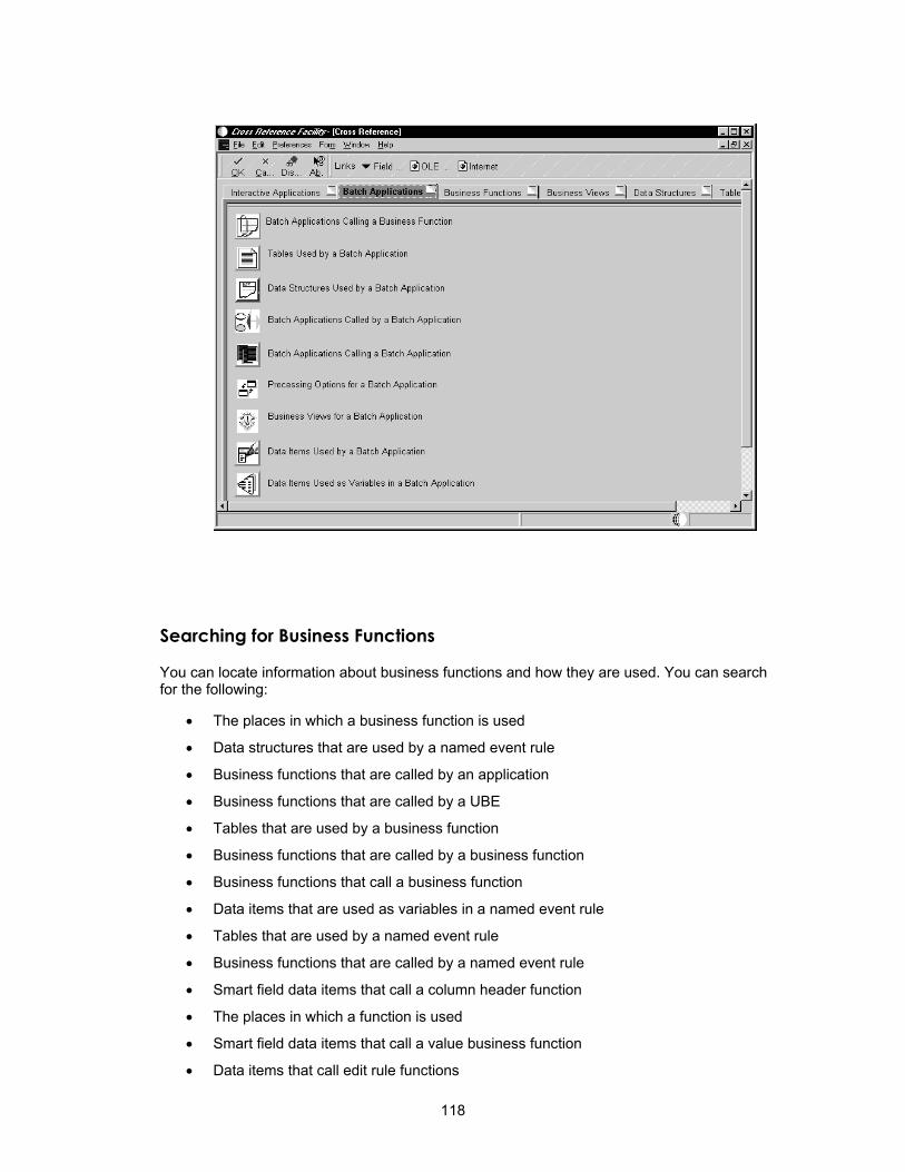
Searching for Business Functions
You can locate information about business functions and how they are used. You can search for the following:
• The places in which a business function is used
• Data structures that are used by a named event rule
• Business functions that are called by an application
• Business functions that are called by a UBE
• Tables that are used by a business function
• Business functions that are called by a business function
• Business functions that call a business function
• Data items that are used as variables in a named event rule
• Tables that are used by a named event rule
• Business functions that are called by a named event rule
• Smart field data items that call a column header function
• The places in which a function is used
• Smart field data items that call a value business function
• Data items that call edit rule functions
118

• Data items that call display rule functions
• Search source and header files by string
• Table event rules that use a business function
Searching for Business Views
You can locate information about business views and how they are used. You can search for the following:
• The places in which a business view is used
• Applications that use a business view
• UBEs that use a business view
• Forms that use a business view
• Data items for a business view
• Tables for a business view
119

Searching for Data Structures
You can locate information about data structures and how they are used. You can search for the following:
• The places in which a data structure is used
• Applications that use a data structure
• Business functions that use a data structure
• UBEs that use a data structure
• Data items for a processing option
• Data items for generic text data structures
• Data items for a business function data structure
• Data items for all data structures
• Table event rules that use a data structure
120

Searching for Tables
You can locate information about tables and how they are used. You can search for the following:
• The places in which a table is used
• Business functions that use a table
• Applications that use a table
• UBEs that use a table
• Named event rules that use a table
• Forms that use a table
• Data items for a table
• Indices for a table
• Business views that use a table
• Data items that are used by table event rules
• Business functions that are used by table event rules
• Data structures that are used by table event rules
• Tables that are used by table event rules
• Table event rules that use a table
121
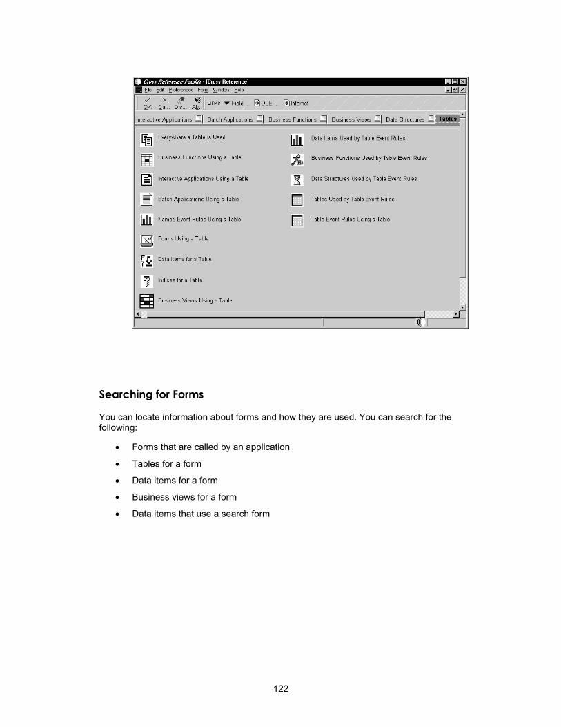
Searching for Forms
You can locate information about forms and how they are used. You can search for the following:
• Forms that are called by an application
• Tables for a form
• Data items for a form
• Business views for a form
• Data items that use a search form
122

Searching for Event Rules
You search for event rules to help you find an existing event that you can use.
► To search for event rules
1. On the search form that you have chosen, choose Event Rules from the Form menu.
123

2. Complete the following fields:
• Object Name
• Form Name
• Data Field Name
Viewing Field Relationships
The Field Relationships form is meaningful only for the following Cross Reference search types:
DA Data items that are used by an application
FA Forms for an application
FI Forms that use a data item
SA Data structure for an application
In these instances, the Field Relationships form displays the control type for a field, such as one of the following:
• BC for a business view column
• FI for a form interconnect control
124
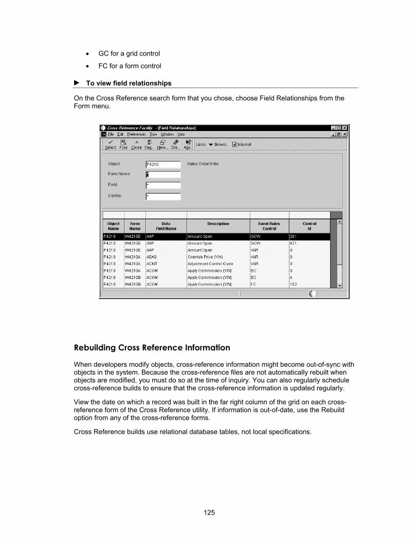
• GC for a grid control
• FC for a form control
► To view field relationships
On the Cross Reference search form that you chose, choose Field Relationships from the Form menu.
Rebuilding Cross Reference Information
When developers modify objects, cross-reference information might become out-of-sync with objects in the system. Because the cross-reference files are not automatically rebuilt when objects are modified, you must do so at the time of inquiry. You can also regularly schedule cross-reference builds to ensure that the cross-reference information is updated regularly.
View the date on which a record was built in the far right column of the grid on each cross-reference form of the Cross Reference utility. If information is out-of-date, use the Rebuild option from any of the cross-reference forms.
Cross Reference builds use relational database tables, not local specifications.
125
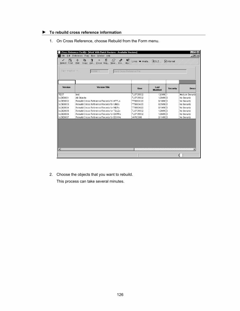
► To rebuild cross reference information
1. On Cross Reference, choose Rebuild from the Form menu.
2. Choose the objects that you want to rebuild.
This process can take several minutes.
126
Application Design
Application Design is the entry point to several tools for creating, generating, running, maintaining, and securing applications. Application Design includes Forms Design for creating forms and Event Rules Design for attaching business logic through event rules. Use Application Design to do the following:
• Access Forms Design for creating forms
• Define processing options
• Run an application
• Access BrowsER
• Create text overrides
• Browse forms in an application
You can use the OneWorld toolset to create applications in different modes, including:
• Windows client
• Java client
• HTML client
See Also Forms Design for complete instructions for creating a form
Processing Options for information about creating and attaching a processing options template to an application
BrowsER for instructions for viewing, enabling, and disabling event rules that are used within forms
Developing Web Applications for more information about developing Web applications
Vocabulary Overrides in the System Administration Guide for information about defining vocabulary overrides for an application
Understanding Applications
An application is a collection of computer programs that perform a specific task. An application retrieves and updates data within a database table. P01012 (Address Book) and P4210 (Sales Order Entry) are examples of applications.
OneWorld includes the following three types of applications:
• Interactive applications
• Batch applications
• Web applications
Understanding Interactive Applications
An interactive application is the interface between a user and a database table, based on a business view. A user uses an interactive application to add, modify, or view data using a form.
127

Understanding Batch Applications
A batch process is an application that processes automatically without user interaction. Table conversions and reports are examples of batch processes.
Understanding Web Applications
To create Web applications, use the OneWorld toolset in the same manner as you would for standard applications. You can then customize your windows applications for the Web.
In addition to installing the Web server, you might need to install the Java generator on the OneWorld developer workstation. Install the Java generator if you are planning to develop new applications or change existing applications. The Java Generator usually is automatically installed when you do a OneWorld client install.
Refer to Developing Web Applications for more information about developing Web applications.
Adding an Interactive Application
An application is an object. Before you can begin developing an application, you must add it so that it exists as an object. You can add a new application, or you can add a version of an existing application.
After the application exists as an object, you can start building the components of the application. You can use Forms Design to design the first form in your application.
128

Create an Interactive Application Object
Use the following process to create an interactive application object.
► To create an interactive application object
1. On Object Management Workbench, click Add.
2. On Add OneWorld Object to the Project, choose the Interactive Application option, and then click OK.
3. On Add Object, complete the following fields, and then click OK:
• Object Name
This field accepts up to 10 characters; however, if you enter more than 8 characters, the entry will be truncated. The J.D. Edwards naming standard for applications is formatted as Pxxxxyyy.
P = Application
xxxx = The system code
yyy = A next number, such as 001 and 002
• Description
Provide up to a 60-character description. It should reflect the subject of the forms within the application, such as Companies and Constants.
129

• Product Code
• Product System Code
• Object Use
Creating an Interactive Version Object
Use the following process to create a version of an interactive application.
► To create an interactive version object
1. On Object Management Workbench, click Add.
2. On Add OneWorld Object to the Project, choose the Interactive Version option, and then click OK.
3. On Adding a Version, enter the object name of the application upon which you want to base this version.
4. On Version Add, complete the following fields, and then click OK:
• Version
This field accepts up to 10 characters; however, if you enter more than 8 characters, the entry will be truncated. The J.D. Edwards naming standard for applications is formatted as Pxxxxyyy.
130

P = Application
xxxx = The system code
yyy = A next number, such as 001 and 002
• Version Title
Provide up to a 60-character description. It should reflect the subject of the forms within the application, such as Companies and Constants.
• Prompting Options
• Security
Forms Design
Use Forms Design to create one or more forms for an application.
Before You Begin Acquire a working knowledge of Windows and have an understanding of the
OneWorld application design process.
Determine which data items are required for each form in the application.
Determine whether any of the existing tables suit your needs. If not, create a table. See Table Design.
Create a business view on which to base a form. See Business View Design.
What is a Form?
A form is the interface between a user and a table. This interface should perform the following functions:
• Present data logically
• Contain the functions that are necessary to enter and manipulate data
131

A single application can contain one or more forms. Usually, a Find/Browse form is the first form that appears in the application. It enables the user to locate a specific record with which he or she wants to work. Upon selecting a record, a subsequent form, such as a Fix/Inspect form, automatically appears, on which the user can view or modify data for that record.
Elements of a Form
Form Type The form type establishes the basic purpose of a form. Each form type has default controls and processes.
Business Views In an application, business views link forms and tables. You must associate all forms, except the Message form, with a business view.
Controls All objects on a form are controls. Controls include grids, check boxes, radio
132

buttons, push buttons, and more.
Properties In application design, the following types of properties exist: application, form, control, and grid. Properties define appearance and function.
Data Structure A data structure defines the data that can be passed between forms within an application or between applications. After the data structure of a form is defined, use form interconnections to indicate the direction of the flow of data between forms.
Event Rules Event Rules can contain processing instructions for specific events. Events are actions that occur on a form, such as clicking a button or using the Tab key to move out of a field. Use event rules to attach business logic to any event.
Events are triggered either as a result of user interaction with a control, such as clicking a button, or as a result of a system-controlled process, such as loading a grid.
See Understanding Form Types for a discussion of each form type.
Understanding Form Types
When you create a new form, you must initially specify a form type. You must understand the available form types because each form has characteristics that accommodate different tasks. For example, the Find/Browse form includes a Find option to search for records across the table and a grid to display those records.
J.D. Edwards Design Standards
J.D. Edwards design standards ensure a consistent design approach for all applications. While many of these standards apply to all form types, each form type also has specific standards. See the Development Standards Application Design Guide for a complete list of standards.
133
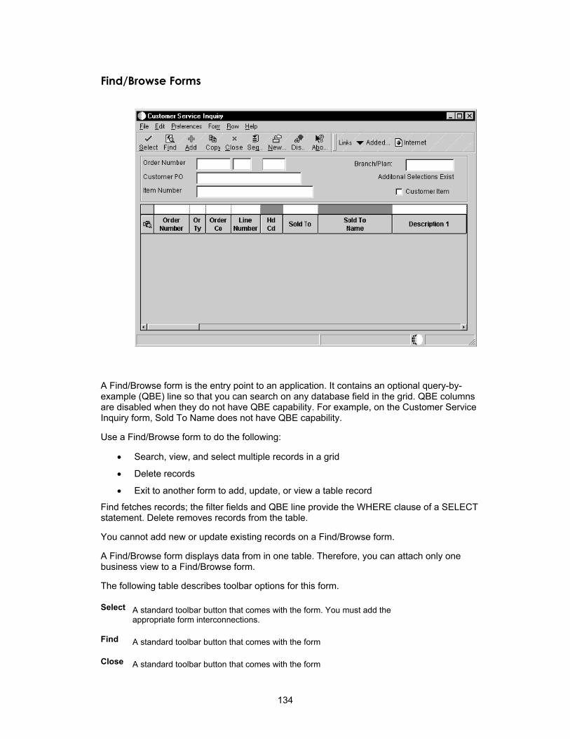
Find/Browse Forms
A Find/Browse form is the entry point to an application. It contains an optional query-by-example (QBE) line so that you can search on any database field in the grid. QBE columns are disabled when they do not have QBE capability. For example, on the Customer Service Inquiry form, Sold To Name does not have QBE capability.
Use a Find/Browse form to do the following:
• Search, view, and select multiple records in a grid
• Delete records
• Exit to another form to add, update, or view a table record
Find fetches records; the filter fields and QBE line provide the WHERE clause of a SELECT statement. Delete removes records from the table.
You cannot add new or update existing records on a Find/Browse form.
A Find/Browse form displays data from in one table. Therefore, you can attach only one business view to a Find/Browse form.
The following table describes toolbar options for this form.
Select A standard toolbar button that comes with the form. You must add the appropriate form interconnections.
Find A standard toolbar button that comes with the form
Close A standard toolbar button that comes with the form
134
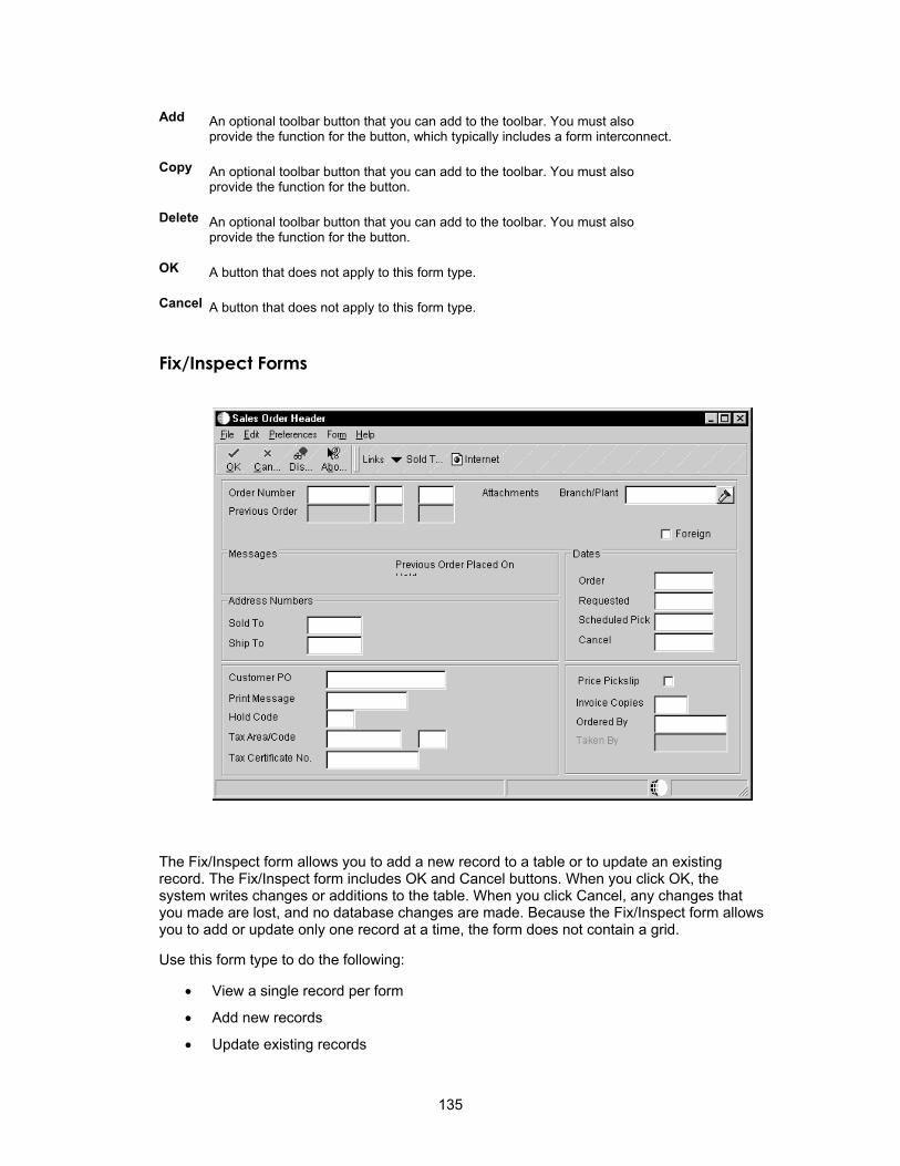
Add An optional toolbar button that you can add to the toolbar. You must also provide the function for the button, which typically includes a form interconnect.
Copy An optional toolbar button that you can add to the toolbar. You must also provide the function for the button.
Delete An optional toolbar button that you can add to the toolbar. You must also provide the function for the button.
OK A button that does not apply to this form type.
Cancel A button that does not apply to this form type.
Fix/Inspect Forms
The Fix/Inspect form allows you to add a new record to a table or to update an existing record. The Fix/Inspect form includes OK and Cancel buttons. When you click OK, the system writes changes or additions to the table. When you click Cancel, any changes that you made are lost, and no database changes are made. Because the Fix/Inspect form allows you to add or update only one record at a time, the form does not contain a grid.
Use this form type to do the following:
• View a single record per form
• Add new records
• Update existing records
135
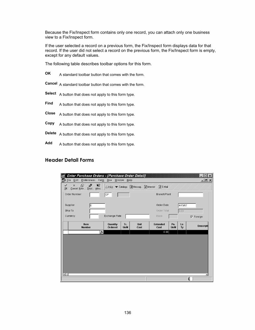
Because the Fix/Inspect form contains only one record, you can attach only one business view to a Fix/Inspect form.
If the user selected a record on a previous form, the Fix/Inspect form displays data for that record. If the user did not select a record on the previous form, the Fix/Inspect form is empty, except for any default values.
The following table describes toolbar options for this form.
OK A standard toolbar button that comes with the form.
Cancel A standard toolbar button that comes with the form.
Select A button that does not apply to this form type.
Find A button that does not apply to this form type.
Close A button that does not apply to this form type.
Copy A button that does not apply to this form type.
Delete A button that does not apply to this form type.
Add A button that does not apply to this form type.
Header Detail Forms
136

The Header Detail form allows you to work with data from two separate tables. You can use this form to add or update a single header record. You can also add, update, or delete multiple detail records from the same form.
The Header Detail form includes an input-capable grid so that you can add or update detail records. Click OK to perform updates or adds to both tables that are associated with the form. When you click Cancel, any changes are lost and no database changes are made.
Because the Header Detail form allows you to update or add records from two different tables, you can attach two business views to a Header Detail form. Attach one business view to the grid and the other to the form, updating both tables from a single form. You can use the Header Detail form for one-to-many relationships.
The following table describes toolbar buttons for this form.
OK A standard toolbar button that comes with the form.
Cancel A standard toolbar button that comes with the form.
Find A button that you can add to the toolbar. You must also provide the function for the button.
The system performs a standard fetch, just as it does when you enter the form.
Delete A button that you can add to the toolbar. Although the system deletes the record, you might want to add other logic here, as well.
Select A button that does not apply to this form type.
Close A button that does not apply to this form type.
Copy A button that does not apply to this form type.
Add A button that does not apply to this form type.
137

Headerless Detail Forms
The Headerless Detail form displays multiple records from a single table that is not normalized. Because this form updates only one table, you can attach only one business view to the form.
The Headerless Detail form contains an input-capable grid, where you can add or update detail information. The header portion of the form displays data that is common to all of the detail records in the grid. Both header and detail information comes from the same business view.
Click OK to perform changes or additions to the table. When you click Cancel, any changes that you made are lost, and no database changes are made.
Use this form type to do the following:
• Display multiple records in a grid
• View, add, change, and delete records
The following table describes toolbar buttons for this form.
OK A standard toolbar button that comes with the form.
Cancel A standard toolbar button that comes with the form.
Find A button that you can add to the toolbar. You must also provide the function for the button.
The system performs a standard fetch, as it does when you entered the form.
138

Delete A button that you can add to the toolbar. You must also provide the function for the button.
Select A button that does not apply to this form type.
Close A button that does not apply to this form type.
Copy A button that does not apply to this form type.
Add A button that does not apply to this form type.
Search and Select Forms
Use this form to locate a value and return it to the calling field. The Search and Select form is called using a visual assist (flashlight) or hyper-control.
This form only displays information; you cannot enter information in the fields. Therefore, the form contains Select and Close options.
The Search and Select form includes a non-input capable grid in which you can view multiple records in one table. The grid displays valid values. When a user chooses a value from the grid and clicks Select, that value automatically returns to the calling field.
Because you use this form to view records from only one table, you can attach only one business view to a Search and Select form. You use a separate application for this form. This form improves performance by fetching only necessary fields, and it exists in its own application.
The data structure for this form should contain only one element.
139

After you create a Search and Select application, you must attach the Search and Select form to the specific data item for which it was created. You do this using the visual assist trigger in the data dictionary or the overrides in the property sheet for a particular control. You use the data dictionary for all instances and the override for just one instance.
The following table describes toolbar buttons for this form.
Select A standard toolbar button that comes with the form.
The Select action automatically returns to the calling form. You do not need to add form interconnects.
Find A standard toolbar button that comes with the form.
Close A standard toolbar button that comes with the form.
Copy A button that does not apply to this form type.
Delete A button that does not apply to this form type.
OK A button that does not apply to this form type.
Cancel A button that does not apply to this form type.
Add A button that does not apply to this form type.
Message Forms
Use the Message form to display messages or request action from the user. The form is modal and is also not sizable. You can add only static text and push buttons to this form. This form is the only form that allows standard push buttons, including OK, Cancel, Yes, and No buttons. Do not use form interconnections on this form.
A delete confirmation is a good example of how you can use the Message form.
This form does not have a business view.
This form does not have a toolbar.
140

Parent/Child Forms
You can use the Parent/Child form to represent parent/child relationships in an application. The form has a Parent/Child control in the position in which the grid resides in a Find/Browse form. This control presents a tree view in the left portion of the control, which displays a visual representation of the Parent/Child relationship. The right portion of the composite control displays a grid in browse mode. A movable bar separates the tree view and grid. Use it to resize either view horizontally. The grid displays the detail information for the nodes of the tree. The Parent/Child form uses one business view.
Two modes are available on the Parent/Child form. You can choose the default mode or show all details. The default mode displays the detail for all nodes at the same level in the tree. As you switch levels in the tree, the grid lines change to reflect your level. If you choose to show all details, no one-to-one correspondence exists between the nodes in the tree and the grid lines. You can also load pre-expanded trees so that, if you click Find, the tree displays all levels instead of loading only one level of nodes at a time. If you choose this option, it appears as an option on the right mouse menu. You can also allow multiple selections.
Use the Parent/Child form to do the following:
• Represent parent/child relationships.
• Perform normal Find/Browse functions (including FETCH and SELECT WHERE statements) and present information in a tree format.
141

The following table describes toolbar buttons for this form.
Select A standard toolbar button that comes with the form. You must add the appropriate form interconnections.
Find A standard toolbar button that comes with the form.
Close A standard toolbar button that comes with the form.
Add A button that you can add to the toolbar. You must also provide the function for the button, which typically includes a form interconnect.
Copy A button that you can add to the toolbar. You must also provide the function for the button.
Delete A button that you can add to the toolbar.. You must also provide the function for the button.
OK A button that does not apply to this form type.
Cancel A button that does not apply to this form type.
Parent/Child form processing is based on the concept of a parent/child relationship between two data items, either within a table or across different tables. If the parent/child relationship is within a table or business view, it is an inherent relationship. If the parent/child relationship is between two different tables or business views, then the relationship is an established one.
To display explicit parent/child data, the business view that underlies the Parent/Child form should have a parent column and a child column. When any node on the tree for the form is expanded, the system performs a fetch by querying the database for all of the expanded child records for the node. For example, suppose the following:
• Business unit 10 consists of business units 5 and 3.
• Business unit 5 consists of business units 2 and 1.
An inherent parent/child relationship exists between business unit 10 and business units 2 and 1.
To display data in a hierarchy, the business view does not need a parent column and a child column. You must develop the logic to perform a fetch when a tree node is expanded.
The Delete hyperitem deletes the currently-selected node record from the table. You must delete child records, if necessary.
The steps involved in creating a Parent/Child form are different from the steps for creating other form types. To create a Parent/Child form, complete the following steps:
1. Create the form in Form Design Aid
2. Select a business view
3. Highlight the grid and add columns to the grid
4. Add filter fields to the form
From the business view, choose the Parent field as the filter because the tool uses this field for fetches from the database.
The previous steps are almost identical to the steps for setting up a Find/Browse form. From this point on, you must complete unique steps to complete the Parent/Child form. See Working with Controls for information about completing the Parent/Child form design.
142

Creating a Form
You use Forms Design to create one or more forms that appear in an application. These forms are the visual interface for the end-user of your application and enable that user to view, add, or modify data that is stored in one or more tables.
See Also Understanding Form Types for information about the types of forms that are available
in OneWorld
Business View Design for instructions for creating a business view
Before You Begin Create a table if you cannot use an existing one
Create a business view upon which to base a form
Add an application in the Object Librarian
Understand the different form types
Determine which data items are required for each form in the application
Select a Form Type
Select a form type to support how you want users to interact with the form and the functions that you want to be available to users. See Understanding Form Types for more information about the types of forms and their underlying functions.
► To select a form type
1. On Interactive Application Design, click the Design Tools tab, and then click Start Form Design Aid.
2. From the Layout menu, choose Size to Guide to make your forms a standard size.
The form guide appears as a blue box.
3. From the Form menu, choose Create, and select one of the following form types:
• Find/Browse
• Fix/Inspect
• Header Detail
• Headerless Detail
• Search and Select
• Parent/Child
• Message Form
An appropriate properties form appears.
On Form Properties, the business view name appears in the gray area below the title only after you define your form properties and select a business view for your form.
Forms Design automatically assigns a name using the format WzzzzzzzzA, where:
143
W = Form
zzzzzzzz = The application name
A = A letter that indicates that the form is the first form created in the application. It is usually, but not always, the entry point to the application. Subsequent forms are assigned sequential letters, such as B for the second form, C for the third and so on.
For example, the application P0101 has two forms. The first form, Work with Addresses, is the entry point and is assigned the name W0101A. The second form, Address Book Revisions, is assigned the name W0101B.
Define Form Properties
Form Properties allow you to define the form the way that you want to. For example, you can specify the title, font, size, and color. Use the following process to set the functions of the form.
► To define form properties
1. On the Properties form, complete the following field:
Provide a form description based on the form type:
Find/Browse - Work With followed by the subject of the application, such as Work With Companies, Work With Constants.
Fix/Inspect, Header Detail and Headerless Detail - should reflect the topic covered, such as Supplier Information, Item Master Revisions, Purchase Order Entry.
For lower level forms, identify the form that called the form by appending the calling form's title, such as Enter Voucher - G/L Distribution.
When the title of a form includes a verb, use an active verb instead of a nominalization, such as Work With Vouchers.
2. Click one or more of the following Style options:
Entry Point indicates that the form is the first form displayed when the application is accessed.
See Transaction Processing for instructions about defining boundaries for transaction processing.
• HTML Auto Refresh (Legacy)
See Understanding the HTML Client for information about turning on and off HTML post for all non-critical events on a form.
3. Choose a form size from the Form Guide drop-down menu.
4. Click the following buttons to further alter or define the form:
• Font
• Options
• Wallpaper
144
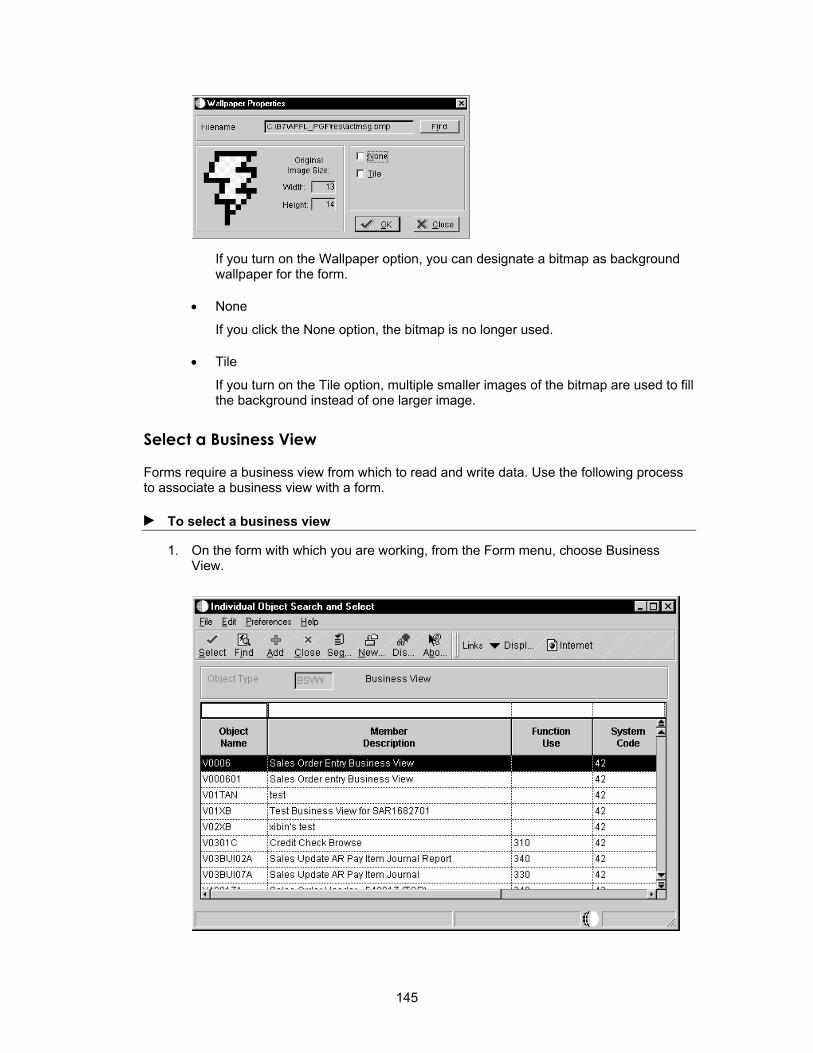
If you turn on the Wallpaper option, you can designate a bitmap as background wallpaper for the form.
• None
If you click the None option, the bitmap is no longer used.
• Tile
If you turn on the Tile option, multiple smaller images of the bitmap are used to fill the background instead of one larger image.
Select a Business View
Forms require a business view from which to read and write data. Use the following process to associate a business view with a form.
► To select a business view
1. On the form with which you are working, from the Form menu, choose Business View.
145

2. Choose the business view to attach to the form.
Revise Information about a Form
You can assign and change data, such as the description of a form and its help ID, as well as metadata, such as its product code.
► To revise information about a form
1. On Interactive Application Design, click the Design Tools tab, and then click View Forms.
2. On Work with Forms, choose one of the following options:
• Local Forms
• Checked-in Forms
When you create a form, it is local to your machine until you check in the form. When you check in the form, the system updates the Form Information File table (F9865). You can view forms that have been checked in or forms that are local to your machine.
3. Choose one of the available forms to view or revise more detailed information about the form.
146
Delete a Form
If you have a form in your application that you no longer need, you can delete it. Ensure that do not want the form because you cannot recover it after you delete it.
► To delete a form
1. On Form Design Aid, choose Destroy from the Form menu.
2. Confirm the deletion.
Caution After you delete a form, you cannot retrieve it.
Alternately, you can delete a form on Work with Forms by choosing the form to delete and then clicking Delete.
Designing a Form Layout
Forms Design includes features that help you to define your form layout.
Selecting and Moving Controls
Select and move controls as you design the form.
► To move a control
1. In Forms Design, on the form with which you are working, position the mouse pointer over the control.
The pointer changes to the hollow square design tool.
2. Click and hold the mouse button as you drag the control to where you want it, and then release the mouse button.
► To select and move a group of controls
1. On the form with which you are working, place the mouse pointer outside the group of controls that you want to select.
2. Press and hold the mouse button. The pointer changes to the pencil design tool.
3. Drag the mouse to the opposite corner of the group of controls.
As you drag the mouse, a rectangle is drawn from the point that you first placed the arrow design tool. Verify that the rectangle completely surrounds all of the controls that you want to select.
4. Release the mouse button. A box surrounds the selected group of controls.
5. Position the mouse pointer over the selected group.
The pointer changes to the hollow square design tool.
6. Click and hold the mouse button as you drag the group to where you want it, and then release the mouse button.
147

► To move a control and static text
1. On the form with which you are working, position the mouse pointer over the shaded area between the static text and the control box.
2. When the pointer becomes the hollow square design tool, press and hold the mouse button.
When the crosswire appears, you can move both the static text and the control box together.
3. Drag the controls to where you want them. Release the mouse button.
If the static text and the control box are too close together, the hollow square design tool does not appear in the shaded area. If this occurs, move the text and the control farther apart. You can also use the pencil tool to draw a box around just one control and move it independently.
Changing the Size of Grids, and Controls
Forms Design allows you to change the size of your grids and controls. You might need to change either the size of grids and controls to compensate for the size of your field descriptions or the size of the data itself.
You can size controls by either using the mouse or by using the Size command. The Size command allows you to specify placement of the controls on the form. You can specify size and placement for only one control at a time.
J.D. Edwards Design Standards The length of string fields must be at least the minimum size of the string of characters.
► To size controls using the mouse
1. On the form with which you are working, choose the control.
Handles appear on the control.
2. Move the mouse pointer over one of the handles.
The mouse pointer changes to the filled-square design tool.
3. To change the width, drag a handle at the left or right of the control.
To change the height, drag a handle at the top or bottom of the control.
To change both the width and the height, drag a handle at the corner of the control.
Note Resize the form and grid using the same method.
► To size and place a control using the Size command
1. On the form with which you are working, choose the control.
148

2. From the Layout menu, choose Size.
3. To specify the exact control size in pixels, complete the following fields:
4. To have the tool automatically calculate the width of a control, type the number of characters in the Width Calculator field, and click one of the following options:
• Average
• Maximum Characters
Average width is about the size of a lowercase x. Maximum width is about the size of an uppercase W.
5. Click the Calculate button.
The new calculated width, in pixels, appears in the Width field.
6. Click OK to accept the width.
The Resize Control window remains open for additional changes.
7. To specify the exact position of the control on the form, complete the following fields in pixels:
• Top
• Left
Pixels are calculated from the top and left margins of the form.
8. Click Close when you are finished.
Using the Cut, Copy, and Paste Commands in Forms
You use the Cut, Copy, and Paste commands from the Edit menu to move and copy controls within the same form or on another form within the same application. You can also create a new form or application into which to paste the controls.
► To cut, copy, and paste controls
1. On the form with which you are working, choose the control or group of controls.
2. From the Edit menu, choose Copy or Cut.
3. Select the form into which you want to paste the control or group of controls.
149

4. From the Edit menu, choose Paste.
5. Move the outline of the controls to the desired location on the form.
6. Click once to place the controls.
When you copy, cut, or paste the control, the system also copies, cuts, or pastes the event rules that are attached to the control. You cannot copy or paste complex controls, such as a tab control, grid control, or grid column.
Aligning Controls
Forms Design simplifies the steps required to accurately line up controls in relation to each other in your forms. For example, you might want to align controls horizontally or vertically or verify that a related set of controls has the same width or height.
► To align a group of controls
1. On the form with which you are working, select the group of controls that you want to align.
2. Click the control within the group to which you want to align the group of controls.
3. From the Layout menu, choose one of the following commands:
• Align Left
• Align Right
• Align Top
• Align Middle
• Align Bottom
• Align Center
► To use an alignment grid to align controls
1. On the form with which you are working, choose Grid Alignment from the Layout menu.
150

2. To determine grid spacing, complete the following fields:
• Vertical/Horizontal Placement
3. Click one or both of the following:
• Snap to Grid
• Display Alignment Grid
Form Design retains the grid alignment settings from session to session. Both of these settings are turned on by default. You must turn on the grid alignment setting when you are developing Web applications because improperly-aligned controls are quite noticeable. Use the snap-to grid for placing, moving, or resizing controls or grid columns.
151

The following example shows a form that displays the alignment grid.
Using Undo and Redo
You use Undo to reverse the last change that you made. You can set the depth on the Undo feature to undo many (over 100) previous changes. However, a large setting requires a large buffer size, and it might lead to performance degradation.
► To set the undo depth
1. On Form Design, choose Set Undo Depth from the edit menu.
2. Enter a number to indicate how many previous steps that you want to be able to undo.
► To undo and redo changes
1. On Form Design, to undo a change (that is, to move backward in the stack of changes), choose Undo from the Edit menu.
Each time that you choose Undo, the tool reverts back by one change.
2. To reapply a change (that is, to move forward in the stack of changes), choose Redo from the Edit menu.
Each time that you choose Redo, the tool reapplies one change.
152

Working with Menu/Toolbar Exits
Menu/Toolbar Exits can be items that are only appear in the menu or items that appear in the menu and on the toolbar. An item must be placed in the menu in order to appear on the toolbar. The toolbar is a visual shortcut to menu items. You can display a bitmap next to an item in a form or row menu or on the toolbar. You can create custom exits, or you can use any of the standard exits that OneWorld provides for a form. You can also modify these standard exits.
To create a Menu/Toolbar exit, complete the following:
1. Designate the exit category
2. Define the exit properties
3. Attach event rule logic, if necessary
4. Select a bitmap for the exit if you are going to show the item on the toolbar
Creating, Editing, or Deleting a Menu/Toolbar Exit
Use the following process to create, edit, or delete menu and toolbar exits.
► To create, edit, or delete a Menu/Toolbar exit
1. In Form Design, on the form with which you are working, choose Menu/Toolbar Exits from the Form menu.
Depending on the form type with which you are working, any of the following standard exits might appear:
OK Accepts the data in the form, clears fields, and remains in the form. However, in update mode, OK closes the form. In add mode, OK might or might not close the form.
Cancel Closes the form and returns to the previous one. Any additions, revisions, or deletions the user made in this form are ignored.
153

2. If you do not want one of the listed exits to appear on your form, choose the exit and click Delete.
3. Choose an exit and click Select to edit its properties.
4. To create a new exit, click Add.
5. On Exit Properties, choose the appropriate class.
The classes that are available depend on the form type. The classes and choices that are available on the Exit Properties form also vary depending on the type of exit that you select.
Form, Row, and View are standard exits, and they are the only Begin categories that you use. All exits that are subordinate to these categories are user defined, and the last one in the list requires an End category. The exits that you create appear on a drop-down menu on the toolbar. If you select a Row category, all exits that are subordinate to it need the Grid option turned on.
6. Complete the following fields:
The short text includes the access key.
The long text appears in the status bar.
7. Complete the Exit Properties form and click OK.
Every Begin category must have a corresponding End category. Many exits can exist between the Begin and End categories.
Adding Bitmaps
No bitmap strips initially appear for you to choose. Bitmap strips are stored in the \package name\res directory, such as the b7\appl_pgf\res directory. The name of each bitmap strip begins with hc_. After you have set that strip on an exit for a Begin category, it appears for any item in that category. You can also use third-party tools to modify and create your bitmaps.
154

► To add a bitmap
1. On Menu/Toolbar Exits, choose a Begin category.
2. On Exit Properties, click the Bitmap button.
3. Type the file name of your bitmap strip in the File field.
4. Click Add.
5. Choose the strip that you want to use and click Select to apply it to all of the exits in that category.
155
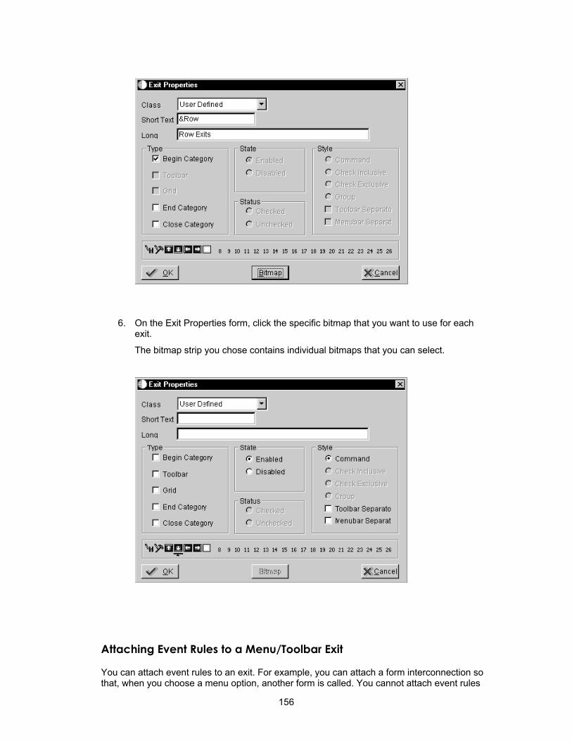
6. On the Exit Properties form, click the specific bitmap that you want to use for each exit.
The bitmap strip you chose contains individual bitmaps that you can select.
Attaching Event Rules to a Menu/Toolbar Exit
You can attach event rules to an exit. For example, you can attach a form interconnection so that, when you choose a menu option, another form is called. You cannot attach event rules
156
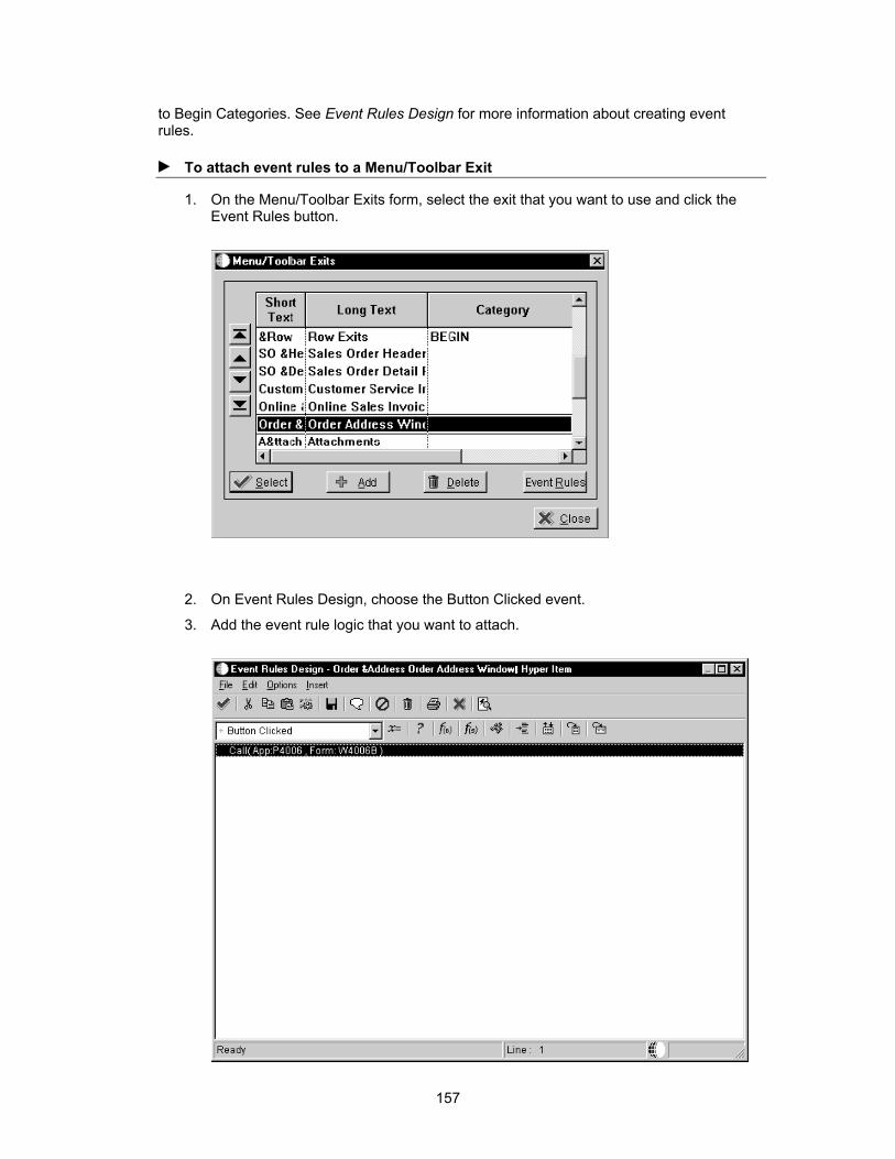
to Begin Categories. See Event Rules Design for more information about creating event rules.
► To attach event rules to a Menu/Toolbar Exit
1. On the Menu/Toolbar Exits form, select the exit that you want to use and click the Event Rules button.
2. On Event Rules Design, choose the Button Clicked event.
3. Add the event rule logic that you want to attach.
157
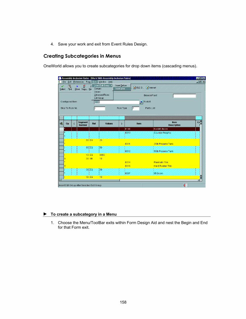
4. Save your work and exit from Event Rules Design.
Creating Subcategories in Menus
OneWorld allows you to create subcategories for drop down items (cascading menus).
► To create a subcategory in a Menu
1. Choose the Menu/ToolBar exits within Form Design Aid and nest the Begin and End for that Form exit.
158
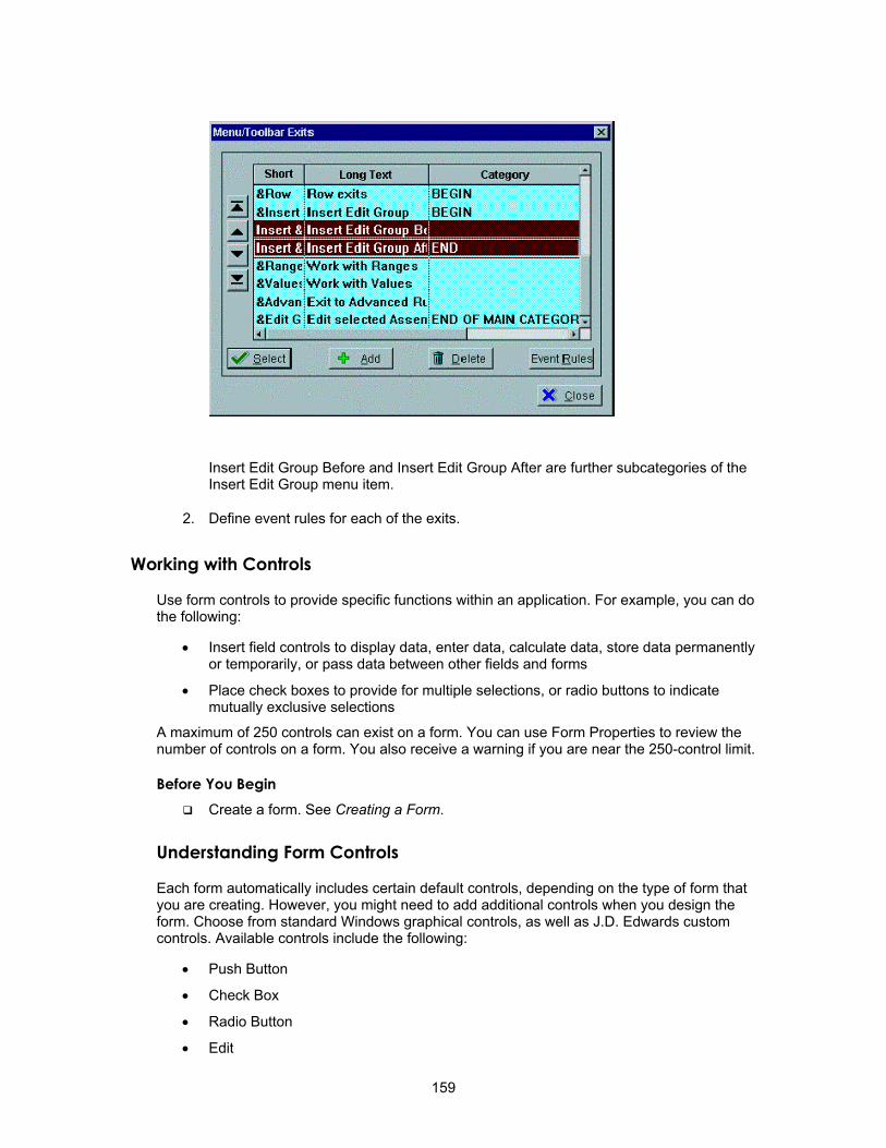
Insert Edit Group Before and Insert Edit Group After are further subcategories of the Insert Edit Group menu item.
2. Define event rules for each of the exits.
Working with Controls
Use form controls to provide specific functions within an application. For example, you can do the following:
• Insert field controls to display data, enter data, calculate data, store data permanently or temporarily, or pass data between other fields and forms
• Place check boxes to provide for multiple selections, or radio buttons to indicate mutually exclusive selections
A maximum of 250 controls can exist on a form. You can use Form Properties to review the number of controls on a form. You also receive a warning if you are near the 250-control limit.
Before You Begin Create a form. See Creating a Form.
Understanding Form Controls
Each form automatically includes certain default controls, depending on the type of form that you are creating. However, you might need to add additional controls when you design the form. Choose from standard Windows graphical controls, as well as J.D. Edwards custom controls. Available controls include the following:
• Push Button
• Check Box
• Radio Button
• Edit
159

• Static Text
• UDC Edit
• Grid
• Parent/Child
• Media Object
• Group Box
• Bitmap
• Tree Control
• Tab Control
• Business View Field
• Data Dictionary Field
You can disable controls at design time and then enable them at runtime using event rules. If a control is disabled, it appears grayed out. If a control is read-only, you can set focus on it or use the Tab key to move to it, but you cannot enter values.
Creating Push Buttons
You can use a push button to initiate an action or a set of actions.
► To create a push button
1. On the form with which you are working, choose Push Button from the Insert menu.
2. Position the control outline on the form, and then click to set the position.
3. To define the push button properties, do one of the following:
• Double-click the push button control
• Choose the push button and then choose Item Properties from the Edit menu.
4. Complete the following field:
160

• Title
5. Click one or more of the following Attributes:
• Tab Stop
• Group
• Disabled
• Visible
• Default Push Button
6. Assign an access key by inserting the ampersand symbol (&) in front of the particular letter in the push button name (optional).
An access key provides a quick way to execute a push button using a combination of the Alt key and the specific alphabetic key. An underlined letter within the push button name identifies an access key. Simultaneously pressing the Alt key and that letter on your keyboard is the same as clicking the button with your mouse.
Creating Check Boxes
You use check boxes to indicate choices. A check mark in a box indicates that you have made a choice. Check boxes are not mutually exclusive. You must associate a check box with a database or dictionary item. You can use a check box to pass a value to an event rule.
See Also Associating Database Items, Dictionary Items, or Descriptions
► To create a check box
1. On the form with which you are working, choose Check Box from the Insert menu.
2. Position the control outline on the form, and then click.
3. To define the check box properties, do one of the following:
• Double-click the check box control
• Choose the check box control and choose Properties from the Settings menu.
161

4. Complete the following field:
• Title
5. Complete the following Value fields:
• Value Checked/Unchecked
6. Click one or more of the following attributes:
• Tab Stop
• Group
• Disabled
• Visible
• No display if currency is OFF
7. Click one of the following justification options:
• Left
• Right
Creating Radio Buttons
You use radio buttons to indicate choices. A filled radio button indicates that you have made a choice. When radio buttons appear in a group box, they should always be mutually exclusive.
162
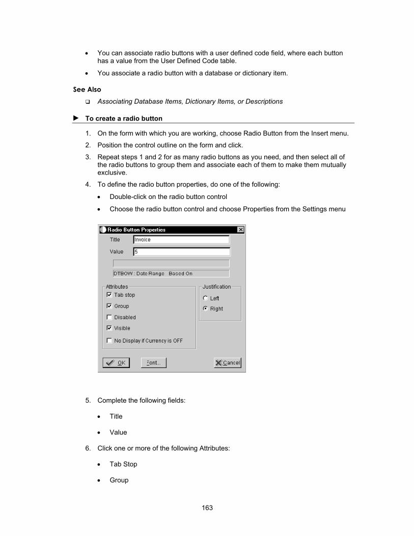
• You can associate radio buttons with a user defined code field, where each button has a value from the User Defined Code table.
• You associate a radio button with a database or dictionary item.
See Also Associating Database Items, Dictionary Items, or Descriptions
► To create a radio button
1. On the form with which you are working, choose Radio Button from the Insert menu.
2. Position the control outline on the form and click.
3. Repeat steps 1 and 2 for as many radio buttons as you need, and then select all of the radio buttons to group them and associate each of them to make them mutually exclusive.
4. To define the radio button properties, do one of the following:
• Double-click on the radio button control
• Choose the radio button control and choose Properties from the Settings menu
5. Complete the following fields:
• Title
• Value
6. Click one or more of the following Attributes:
• Tab Stop
• Group
163
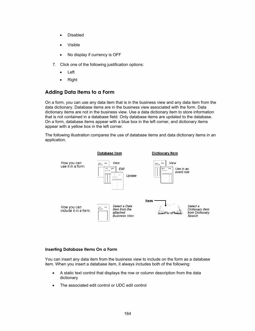
• Disabled
• Visible
• No display if currency is OFF
7. Click one of the following justification options:
• Left
• Right
Adding Data Items to a Form
On a form, you can use any data item that is in the business view and any data item from the data dictionary. Database items are in the business view associated with the form. Data dictionary items are not in the business view. Use a data dictionary item to store information that is not contained in a database field. Only database items are updated to the database. On a form, database items appear with a blue box in the left corner, and dictionary items appear with a yellow box in the left corner.
The following illustration compares the use of database items and data dictionary items in an application.
Inserting Database Items On a Form
You can insert any data item from the business view to include on the form as a database item. When you insert a database item, it always includes both of the following:
• A static text control that displays the row or column description from the data dictionary
• The associated edit control or UDC edit control
164
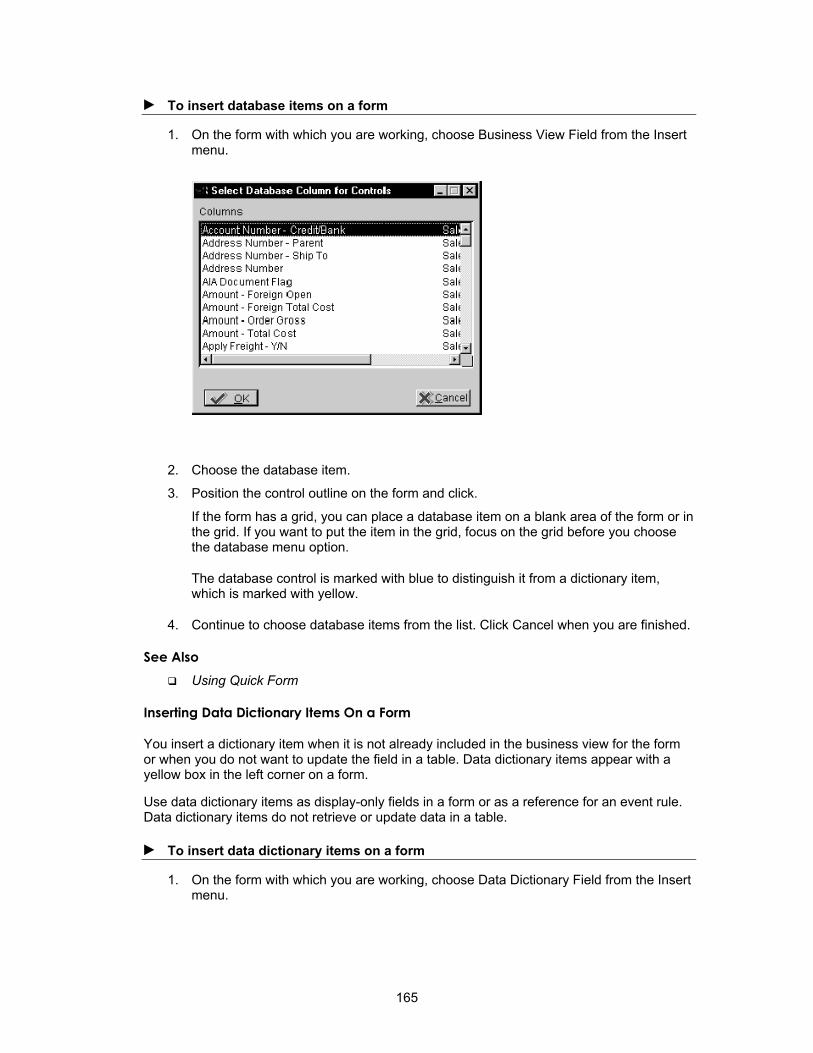
► To insert database items on a form
1. On the form with which you are working, choose Business View Field from the Insert menu.
2. Choose the database item.
3. Position the control outline on the form and click.
If the form has a grid, you can place a database item on a blank area of the form or in the grid. If you want to put the item in the grid, focus on the grid before you choose the database menu option.
The database control is marked with blue to distinguish it from a dictionary item, which is marked with yellow.
4. Continue to choose database items from the list. Click Cancel when you are finished.
See Also Using Quick Form
Inserting Data Dictionary Items On a Form
You insert a dictionary item when it is not already included in the business view for the form or when you do not want to update the field in a table. Data dictionary items appear with a yellow box in the left corner on a form.
Use data dictionary items as display-only fields in a form or as a reference for an event rule. Data dictionary items do not retrieve or update data in a table.
► To insert data dictionary items on a form
1. On the form with which you are working, choose Data Dictionary Field from the Insert menu.
165

2. On Data Dictionary Browse Control, specify search criteria and press Enter.
3. Choose a data dictionary item from the available items and drag it to your form.
4. Position the control outline on the form and click.
If the form has a grid, you can place a data dictionary item either on a blank area of the form or in the grid. If you put the item in the grid, focus on the grid before you choose the dictionary menu option.
The data dictionary control has a yellow box in the left corner to distinguish it from a database item, which has a blue box in the left corner.
Creating Static Text Controls
Use a static text control to display descriptive text, such as a titles or instructions. This text is not associated with a control, and the user cannot change it. You can change it using the Set Control Text system function in event rules.
► To create a static text control
1. On the form with which you are working, choose Static Text from the Insert menu.
2. Position the control outline on the form and click.
3. To define the static text control properties, do one of the following:
• Double-click the static text control
• Choose the static text control, and then choose Properties from the Settings menu
166
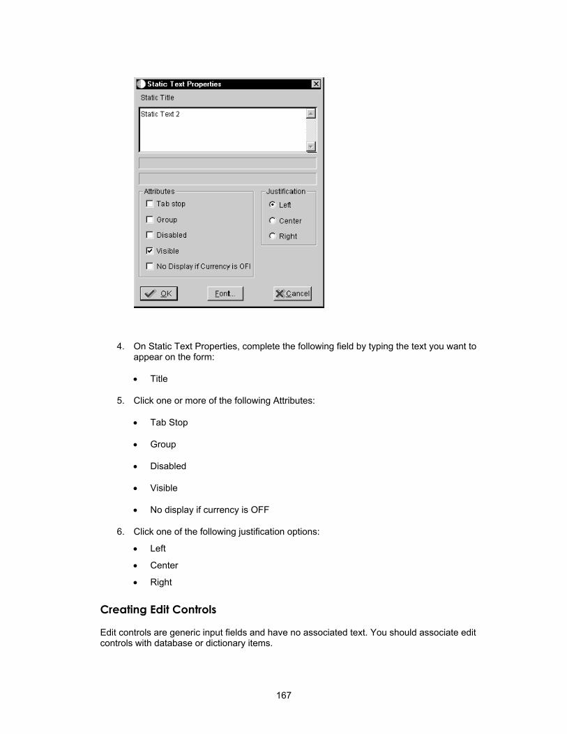
4. On Static Text Properties, complete the following field by typing the text you want to appear on the form:
• Title
5. Click one or more of the following Attributes:
• Tab Stop
• Group
• Disabled
• Visible
• No display if currency is OFF
6. Click one of the following justification options:
• Left
• Center
• Right
Creating Edit Controls
Edit controls are generic input fields and have no associated text. You should associate edit controls with database or dictionary items.
167

If you associate an edit control with a database item, then the value entered by a user at runtime updates the table. If you associate an edit control with a dictionary item, then the value entered at runtime is for display only.
Edit Controls have a type-ahead feature. When a user enters a character in the field, the system searches a history list for a match. If a match exists, it appears in the field with highlighted text. This feature is particularly useful for data entry work because it can reduce the amount of typing required. The history list is stored in alphabetical order in a local file in the Windows root directory. The user can define the length of the history list in the jde.ini file. A user can enable or disable type-ahead editing in User Preferences. Type-ahead is disabled for double-byte languages and multiline edit controls.
► To create an edit control
1. On the form with which you are working, choose Edit from the Insert menu.
2. Position the control outline on the form and click.
3. To define the edit control properties, do one of the following:
• Double-click on the edit control
• Choose the edit control and choose Properties from the Settings menu
4. On Edit Control Properties, complete the following field:
• Event Rules
5. Click one or more of the following Attributes:
• Tab Stop
• Group
• Disabled
168

• Visible
• Update Mode
• Resize All Rows
6. Click one of the following justification options:
• Left
• Center
• Right
7. Click one of the following lines options:
• Lines Single
• Lines Multiple
8. Click one of the following vertical scrolling options:
• Auto Vertical
• Vertical
• None
9. Click one of the following horizontal scrolling options:
• Auto Horizontal
• Horizontal
• None
10. Click the following buttons to further alter the control:
• Font
• Options
• Overrides
► To filter database items
1. On Edit Control Properties, click Filter.
169

2. On Edit Control, choose one of the edit control filter options.
3. Click the Wildcard Display to turn it on, if desired. This option displays an asterisk.
As you add controls to the form, you can indicate how the runtime engine filters the incoming records from the database. For example, if your Find/Browse form has two controls on which you want to filter, the resulting SQL statement that you generate will be an AND condition for each condition. For example, if you have Search Type and Alpha Description as the controls on the form, the filter criteria for Search Description should be >= and the Search Type control should be =. If a user types D and puts a V in the Search Type field, the resulting SQL statement looks like the following:
SELECT * FROM F0101 WHERE (ABAT1 = "V" AND ABDC LIKE "D%") ORDER BY ABAN8 ASC
You might also want to use filter fields when records need to fall between two values. In this case, you use a range filter. For example, in distribution, a status is assigned to each line of the order. One status is the current status and the other status is the next status. In this example, you filter records that are greater than or equal to the present status and less than or equal to the next status. You drop one, filter, and then drop the next one.
Creating UDC Edit Controls
Use a user-defined code (UDC) edit control for a field that accepts only the specific values that appear in a UDC table. Associate a UDC edit control with a database item or data dictionary item.
The visual assist flashlight automatically appears adjacent to the UDC edit control field. When you click the visual assist flashlight, the attached Search and Select form displays valid values for the field.
To create a UDC edit control, you must do the following:
• Associate the data item with a specific UDC table in the data dictionary
• Create a Search and Select form for displaying valid values from the UDC table
170
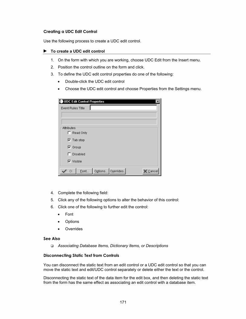
Creating a UDC Edit Control
Use the following process to create a UDC edit control.
► To create a UDC edit control
1. On the form with which you are working, choose UDC Edit from the Insert menu.
2. Position the control outline on the form and click.
3. To define the UDC edit control properties do one of the following:
• Double-click the UDC edit control
• Choose the UDC edit control and choose Properties from the Settings menu.
4. Complete the following field:
5. Click any of the following options to alter the behavior of this control:
6. Click one of the following to further edit the control:
• Font
• Options
• Overrides
See Also Associating Database Items, Dictionary Items, or Descriptions
Disconnecting Static Text from Controls
You can disconnect the static text from an edit control or a UDC edit control so that you can move the static text and edit/UDC control separately or delete either the text or the control.
Disconnecting the static text of the data item for the edit box, and then deleting the static text from the form has the same effect as associating an edit control with a database item.
171

In some cases, the text or description is not necessary. For example, in Purchase Order Entry, the order type follows the order number, but the description, Order Type, is not necessary.
► To disconnect static text from an edit control or UDC control
1. On the form with which you are working, choose the item for which you want to disconnect the static text from the control.
2. From the Edit menu, choose Disconnect.
Now, you can move the static text and edit/UDC box separately. You can use the Cut or Clear option to delete either one. See Data Dictionary for information about setting triggers in the data dictionary.
Creating Media Object Controls
The media object control is a specialized control. You can use this control to allow the user to enter text or attach objects. You can place this control on any form type except the message box.
You can use the media object control in a variety of ways. You can add images, shortcuts to other applications, and text. You can add multiple media objects to a form. You can add multiple text objects to a single media object. You can also add generic files or URLs.
If you want to display a file that is available on the Internet, you can attach the media object control to the form and create a link to the Internet.
After you define your media object queue for the Internet and include a valid HTTP address, you can use the Start Web Browser system function to open the control and display the Internet file.
172
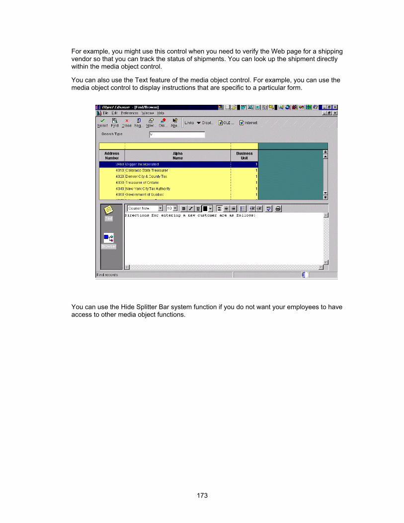
For example, you might use this control when you need to verify the Web page for a shipping vendor so that you can track the status of shipments. You can look up the shipment directly within the media object control.
You can also use the Text feature of the media object control. For example, you can use the media object control to display instructions that are specific to a particular form.
You can use the Hide Splitter Bar system function if you do not want your employees to have access to other media object functions.
173
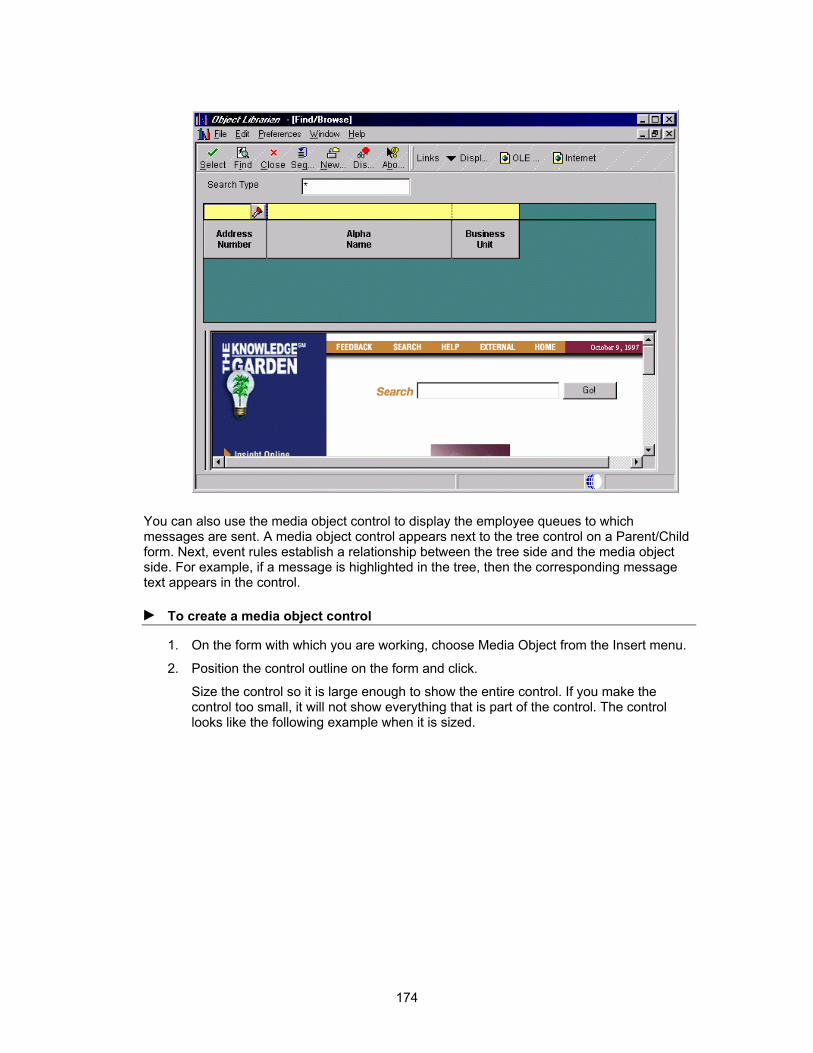
You can also use the media object control to display the employee queues to which messages are sent. A media object control appears next to the tree control on a Parent/Child form. Next, event rules establish a relationship between the tree side and the media object side. For example, if a message is highlighted in the tree, then the corresponding message text appears in the control.
► To create a media object control
1. On the form with which you are working, choose Media Object from the Insert menu.
2. Position the control outline on the form and click.
Size the control so it is large enough to show the entire control. If you make the control too small, it will not show everything that is part of the control. The control looks like the following example when it is sized.
174

3. To define the media object control properties, complete one of the following:
• Double-click the media object control
• Choose the media object control and choose Properties from the Edit menu
175

4. On Media Objects Control Properties, click one or more of the following attributes:
• Tab Stop
• Group
• Disabled
• Visible
5. Click one or more of the following properties:
• Allow Text Items
• Allow RTF Text
• Allow Image Items
• Read Only
• Allow OLE Items
• New Text Item on Open
6. Click one or more of the following code generation options:
• Required entry field
• Default cursor on add mode
• Default cursor on update mode
Creating Bitmap Controls
You can use a bitmap control to create a control that looks like a picture or other artwork. You can then attach event rule logic to the control. For example, you can attach logic to the Button Clicked event on the control so that when a user clicks the control, the application automatically links to a different form.
You can also use the bitmap control for an animated gif instead of a bitmap. An animated gif is particularly useful for Java and HTML applications. The animated gif is animated in Java and TML applications, however, in Windows applications, it does not appear animated, and only the first image of the animated gif file appears.
Creating a Tree Control
You can use the tree control on any form type. Because the tree control is not limited to a particular business view and does not have any default database function, you have more flexibility when you load tree node data. Tree control system functions are also available to further customize tree control functions.
You can use Tree Control system functions to add logic to your control. You can use these system functions for actions such as contracting and expanding nodes or setting bitmaps for nodes.
176

► To create a bitmap control
1. On the form with which you are working, choose Bitmap from the Insert menu.
2. Position the control outline on the form and click.
3. On Bitmap Properties, click Find to find the file that you want to use for your bitmap control.
The Bitmap Properties form displays the bitmap that you chose.
177

4. Complete the following field:
• Tool Tip Text
This text, like Hover Help, appears when the user hovers the mouse pointer over the bitmap.
5. Click one or more of the following attributes:
• Clickable
If you turn on the Clickable option, the system enables a Button Clicked event for the bitmap.
• Maintain Aspect Ratio
If you turn on the Maintain Aspect Ratio option, the bitmap maintains its dimensions when you resize it. This option ensures that your image does not become distorted when you resize it.
► To create a tree control
1. On the form with which you are working, choose Tree Control from the Insert menu.
2. Position the control outline on the form and click.
3. Size the control if needed.
Creating Combo Boxes
You can use a combo (list) box to display a list of items from which the user can choose. The combo box includes the type-ahead feature. You can associate the combo box with a data dictionary item so that it preloads with UDC values. When you create a combo box, use a data dictionary item that has the value that you want and use meaningful UDCs. You can also use event rule logic in your application to load the values.
178
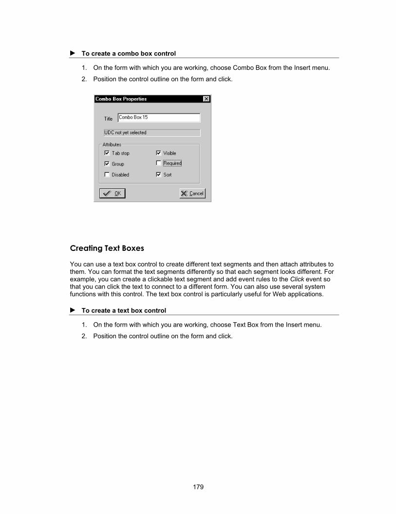
► To create a combo box control
1. On the form with which you are working, choose Combo Box from the Insert menu.
2. Position the control outline on the form and click.
Creating Text Boxes
You can use a text box control to create different text segments and then attach attributes to them. You can format the text segments differently so that each segment looks different. For example, you can create a clickable text segment and add event rules to the Click event so that you can click the text to connect to a different form. You can also use several system functions with this control. The text box control is particularly useful for Web applications.
► To create a text box control
1. On the form with which you are working, choose Text Box from the Insert menu.
2. Position the control outline on the form and click.
179

3. Enter the text that you want to use.
4. Click Add Segment to add additional text segments.
180
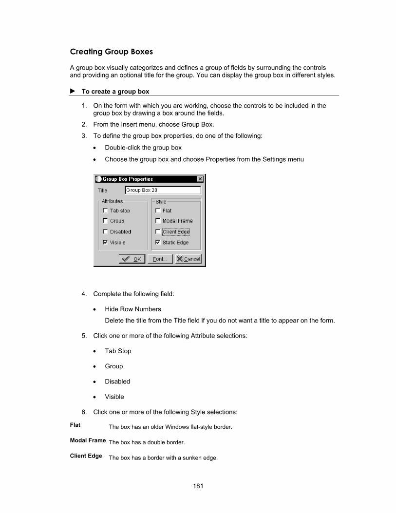
Creating Group Boxes
A group box visually categorizes and defines a group of fields by surrounding the controls and providing an optional title for the group. You can display the group box in different styles.
► To create a group box
1. On the form with which you are working, choose the controls to be included in the group box by drawing a box around the fields.
2. From the Insert menu, choose Group Box.
3. To define the group box properties, do one of the following:
• Double-click the group box
• Choose the group box and choose Properties from the Settings menu
4. Complete the following field:
• Hide Row Numbers
Delete the title from the Title field if you do not want a title to appear on the form.
5. Click one or more of the following Attribute selections:
• Tab Stop
• Group
• Disabled
• Visible
6. Click one or more of the following Style selections:
Flat The box has an older Windows flat-style border.
Modal Frame The box has a double border.
Client Edge The box has a border with a sunken edge.
181

Static Edge The box has a three-dimensional border.
Defining Grid Properties
You can define grid properties, such as the font or sort order for a grid.
► To define grid properties
1. On the form with which you are working, do one of the following to define the grid control properties:
• Double-click the grid
• Choose the grid control and choose Item Properties from the Edit menu
2. Click any of the following grid preferences:
• Hide Row Headers
The row header must appear when you use media objects. The row header is the gray column to the left of the grid row in which the paper clip icon appears.
• Hide Row Lines
This is standard for Find/Browse forms.
182

• Hide Column Lines
• Hide Query By Example
• Resize All Rows
• Resize All Columns
• Update Mode
• Multiple Select
This option must be turned on in order to make a form multiselect, such as to allow multiple grid rows to be selected for an operation. The property event rule for the button (such as Select or Delete) must have the Repeat Event Rule for Grid option turned on.
3. Click any of the following attributes:
• Tab Stop
• Group
• Disabled
• Visible
4. To define properties for a selected column, choose an item from the Grid Columns list and click Select.
5. Click any of the following to specify additional grid properties:
• Font
• Options
For information about grid options, refer to Defining Options For a Grid.
• Data Sort
If you click Data Sort, the following form appears, and you can choose the way in which you want to sort the data.
183

Choose an available column and click the right arrow button to sort on that column. After the column appears in Columns Sorted, choose it and right-click the A/D (ascending/descending) column to toggle to either an ascending or descending sort order for that column. The columns are sorted starting with the top one under Columns Sorted. You can sort on several columns, if necessary. Use the arrows in the menu to change the order of your sorted columns.
See Also Foundation for information about how to customize the grid at runtime
Defining Grid Column Properties
You can set properties for each grid column. On Find/Browse forms, you cannot attach event rules to grid columns.
► To define grid column properties
1. On Grid Properties, choose the grid column for which you want to define properties.
184

2. Click the Grid Column Properties button.
3. Complete the following fields:
• Column Heading 1
• Column Heading 2
185

4. Click one or more of the following attributes:
• Visible
• Disable input
• Disable QBE
5. Click one of the following options to indicate the sort order:
6. Click one of the following display styles:
• Default
• Check Box (Check Box is currently unavailable)
7. Click the following to define additional grid properties:
• Overrides
• Options
• Event Rules
Defining Properties for Parent/Child Controls
The Parent/Child form has a special parent/child control that automatically appears with the form. The control is a composite control with a tree control on the left side and a grid control on the right. The tree and grid control portions both use the same business view. This control is available only on the Parent/Child form. Refer to Understanding Form Types for more information about the Parent/Child form. The following graphic shows a Parent/Child form.
186

► To define properties for the parent/child control
1. On the form with which you are working, perform one of the following:
• Double-click the grid portion of the parent/child control
• Right-click the parent/child control and choose Properties
2. Click any of the following grid preferences:
• Hide Row Numbers
• Hide Row Lines
• Hide Column Lines
• Hide Query By Example
• Show details of all tree nodes
• Resize All Rows
• Resize All Columns
187

• Multiple Select
• Always Hidden
3. Click any of the following attributes:
• Tab Stop
• Disabled
• Group
• Visible
4. Click any of the following drag and drop options:
• Disable Move
• Disable Copy
• Disable Drag & Drop
5. To define properties for a selected column, choose an item from the Parent/Child columns list and click Select.
6. Complete the following field:
• Number of columns joined to
7. Click any of the following buttons to specify additional properties:
• Font
• Options
• Data Sort
You can also double-click the grid to display the properties for the grid. Choose the grid column that you want to display in the tree within the scroll window and select the check box to move it to the tree side of the control. This hides the chosen column from the right side of the grid (the default option is to hide the column unless the checkbox is unchecked) and displays it only in the left side of the control or the tree. This also moves the column description over.
You can select multiple objects; however, they must be at the same node level. Two modes are available. In the first mode, a one-to-one correspondence exists between the tree and the grid. The other mode shows all details of the tree. You can also load trees pre-expanded. This option is on the right mouse menu.
After you complete the above steps, you set up either a parent/child relationship or use event rules to load child nodes to the tree. The method that you use depends on whether your table has an inherent parent/child relationship. In the following examples, the first example describes a situation in which an inherent parent/child relationship exists in a table. The second example describes a situation in which the data does not have an inherent parent/child relationship by keys, but can appear in a hierarchical manner for readability.
You can use event rules and system functions to customize the way in which your parent/child control functions. For example, you can change the top node of a tree or change the node that appears as the first child on a tree.
188

Example: Inherent Parent/Child Relationship This example describes a case in which an inherent parent/child relationship exists in a table. For instance, in the Bill of Material Master File table (F3002), IXKIT is the short item number for the kit. Kits are composed of multiple items within IXKIT, represented by IXITM, the short item number for the item.
Kit item 60038 includes items 60062, 60118, 60126, and other items as its children.
IXTBM IXKIT (Parent)
IXITM (Child) IXKITA IXMMCU IXAITM
M 60038 60062 220 M30 2001
M 60038 60118 220 M30 2006
M 60038 60126 220 M30 2007
Each one of the items (IXITM) can be a kit within itself.
Item 60062 includes 60097, 60935, 61137, and other items as its children.
IXTBM IXKIT (Parent)
IXITM (Child) IXKITA IXMMCU IXAITM
M 60062 60097 2001 M30 2004
M 60062 60935 2001 M30 9011
M 60062 61137 2001 M30 9031
Because this inherent relationship exists within the table, you can develop a parent/child application over the Bill of Material Master File table (F3002), using the V3002A business view.
The following form represents this data.
189

This structure represents data from the same table shown in the parent/child format. When you first inquire on the 60038 item in the filter field, you generate the same SQL statement as you would on a normal Find/Browse form.
When you click on the + node next to item 60062, the runtime engine takes the value of the Item Number and moves it into the Parent Item Number, making it the parent for the fetch.
Complete the following steps to set up the parent/child relationship to be used when the runtime engine loads nodes to the tree:
1. Focus on the parent/child control.
2. From the Form menu, choose Parent/Child Relation.
The following form appears:
190
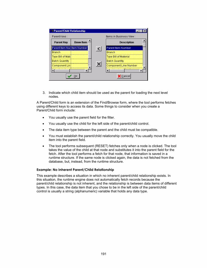
3. Indicate which child item should be used as the parent for loading the next level nodes.
A Parent/Child form is an extension of the Find/Browse form, where the tool performs fetches using different keys to access its data. Some things to consider when you create a Parent/Child form include:
• You usually use the parent field for the filter.
• You usually use the child for the left side of the parent/child control.
• The data item type between the parent and the child must be compatible.
• You must establish the parent/child relationship correctly. You usually move the child item into the parent field.
• The tool performs subsequent (RESET) fetches only when a node is clicked. The tool takes the value of the child at that node and substitutes it into the parent field for the fetch. After the tool performs a fetch for that node, that information is saved in a runtime structure. If the same node is clicked again, the data is not fetched from the database, but, instead, from the runtime structure.
Example: No Inherent Parent/Child Relationship This example describes a situation in which no inherent parent/child relationship exists. In this situation, the runtime engine does not automatically fetch records because the parent/child relationship is not inherent, and the relationship is between data items of different types. In this case, the data item that you chose to be in the left side of the parent/child control is usually a string (alphanumeric) variable that holds any data type.
191

The parent/child relationship is not inherent to a particular table because the application is accessing multiple tables, such as Company Master, Account Master, and Chart of Accounts, to get information.
Page-at-a-Time Processing Page-at-a-time processing ensures that each fetch fetches only one page of data. Page-at-a-time processing is the default mode for all parent/child forms.
During page-at-a-time processing in standard mode, the page size is the number of nodes that can fit in the current view. When the Find process begins, only one page of the first level nodes is fetched from the table and inserted in the tree. When the user scrolls down, a new page of data is fetched.
Page-at-a-time processing for the expand-all style of Parent/Child forms is similar to that for standard mode. When the Find process starts, one page of first-level nodes is fetched from the table and inserted into the tree. Then, all of the first-level nodes are expanded. Each expansion fetches only one page of data. Because the tree expands exponentially in expand-all mode, a very deep tree might affect performance.
Tree Nodes When the parent and child nodes come from different tables or are of different data types, the parent/child relationship is not automatically set up. In this case, the runtime engine does not automatically fetch the child database records because it does not know the table from which to retrieve them.
192

Parent Nodes If possible, use the runtime engine to load the initial set of parent nodes to the tree for you. You do this by using the based-on view, which is a view over the table for the upper-most node. You can use a parent filter in the control, and the runtime engine loads the first level nodes to the tree. If you cannot do this, you must insert the first-level nodes yourself. To do this, you typically use Table I/O on the Button is Clicked event of the Find button. You use the same methods as you use to insert child nodes. Use a Suppress Find system function to stop the runtime engine from attempting to load any nodes.
Child Nodes Whenever a node is expanded, the system function Suppress Fetch on Node Expand is called from the event Tree Node Is Expanded. This tells the runtime engine not to do any fetches because event rules will handle the loading of the child nodes. Tree Node Is Expanded is the main event of the application. This event occurs when the tree node is expanding (such as when the plus next to a child node is expanded for the first time). You place event rules on this event to read the next records to be loaded to the tree as children of the expanded node. You can use table I/O or business functions to retrieve these records. Often the children come from different tables, based on the type of parent node that is expanded. If possible, you should perform a SELECT and then use the FETCH NEXT command to retrieve records in a DO WHILE loop. The GB runtime data structure is populated with data from the records read in the loop, and then an INSERT GRID BUFFER ROW system function is called. This parent child system function is different from the INSERT GRID BUFFER ROW in the normal GRID section. At this point, you also can set your custom tree bitmaps using the SET TREE NODE BITMAP system function.
Example In the following example, event rules are attached to an application on the Tree Node is Expanding event:
Suppress Fetch on Node Expand(FC Parent/Child)
//
// Here are the variables to get out of the account and the business unit loop
// being initialized.
VA frm_OutOfLoop = ”0”
VA frm_ExistAcctLoop = ”0”
//
// If Loop looking at the GC Business Unit Field.
If GC BusinessUnit is equal to <Blank>
//
// Select the F0006 differently if there is one company or all companies
//
F0006.Open
If VA frm_AllCompanies is equal to ”1”
VA frm_CurCompany = GC Co
F0006.Select
Else
VA frm_CurCompany = BC Company
F0006.Select
193

End If
//
// While Loop which fetches all the all the business unit for a specific company.
// If the company changes we get out of the loop.
While VA frm_OutOfLoop is equal to <Zero>
// Fetch the records from the F0006 Table.
F0006.FetchNext
GB BusinessUnit = GB Companies
If SV File_IO_Status is equal to CO SUCCESS
GB Co = BC Company
VA frm_PreCompany = BC Company
VA frm_ConcateBuDesc = ” ”
VA frm_ConcateBuDesc = concat([VA frm_ConcateBuDesc],[VA frm_NameOfBU])
GB CompanyStructure = concat([GB Companies],[VA frm_ConcateBuDesc])
GB Companies = concat([GB Companies],[VA frm_ConcateBuDesc])
//
// Tells the Level of the Tree Structure.
GB LevelOfTreeInt = ”1”
//
Insert Grid Buffer Row(FC Parent/Child, <After Last Row>, <Yes>, <No>, <No>, <No>, <No>, <Yes>)
Set Tree Node Bitmap(FC Parent/Child, <Last Grid Row>, BussUnit.bmp, <Yes>)
//
//
If VA frm_PreCompany is not equal to VA frm_CurCompany
VA frm_OutOfLoop = ”1”
End If
Else
VA frm_OutOfLoop = ”1”
End If
End While
F0006.Close
Else
// Loop thru the F0901 to get the corresponding accounts.
//
VA frm_CURBU = GC BusinessUnit
F0901.Open
F0901.Select
If SV File_IO_Status is equal to CO ERROR
//
End If
//
194

// While Loop to pick up the accounts till the Fetch Fails.
While VA frm_ExistAcctLoop is equal to <Zero>
F0901.FetchNext
GB Sub = VA frm_DBSUB
GB ObjAcct = VA frm_DBOBJ
GB Name = VA frm_AcctDesc
GB BusinessUnit = VA frm_CURBU
VA frm_AcctDesc = concat([VA frm_BLANKS],[VA frm_AcctDesc])
GB AccountID = VA frm_AIDF0901
GC AccountID = VA frm_AIDF0901
If SV File_IO_Status is equal to CO ERROR
VA frm_ExistAcctLoop = ”1”
Else
GC Companies = ” ”
GB Companies = ” ”
Business Unit, Object, Subsidiary Merge
GB Companies = concat([VA frm_DBANI],[VA frm_AcctDesc])
GB CompanyStructure = concat([VA frm_DBANI],[VA frm_AcctDesc])
GC Companies = VA frm_AIDF0901
//
// Tells the level of the Tree Structure ’2’
GB LevelOfTreeInt = ”2”
//
Insert Grid Buffer Row(FC Parent/Child, <After Last Row>, <Yes>, <No>, <No>, <No>, <No>, <No>)
Set Tree Node Bitmap(FC Parent/Child, <Last Grid Row>, accounts.bmp, <Yes>)
End If
End While
End If
FC BUFrom = ” ”
Dragging and Dropping When a Parent/Child form is created, both move and copy drag-and-drop operations are enabled. You can turn these options off in the properties for the form. When drag-and-drop is turned off and a user attempts to drag a node, the cursor indicates that dragging is not allowed, and none of the drag events executes. You can control operations to the database using the following drag-and-drop events:
• Begin Drag - If you allow drag-and-drop, then, on the Begin Drag Operation event, GCs are copied to GBs.
• Drag Over Node - You can attach event rule logic to this event to verify that the node on which the dragged record is about to be dropped is a valid situation. If it is not, you can use a system function to change the cursor to a No Drop cursor to indicate that dropping the record there is not allowed. If the cursor is not the No Drop cursor, when the record is dropped, the event End Drag runs.
195

• End Drag - You can attach event rules to this event to update or insert information that has been moved or copied via the drag. Be aware of the effect of using Insert Grid Buffer Row in the End Drag event, as well as deleting the grid row dragged if the operation is a Move.
• Drag Mode - You can verify the Drag Mode system value at any time to determine the type of drag that a user is performing. For example, you can determine whether the drag is a move or a copy.
Tree Node is Selected This event runs every time a user selects a tree node, either by clicking on it once with the mouse or by moving an arrow up and down the nodes. You can place event rules that need to run when a mode is selected on the Tree Node is Selected event. The Work Center application uses this feature to load the media object that appears next to the tree with the message information for each node. You can also use this event when you need to protect controls or exits, based on the kind of node that the user selects.
Defining Options for Forms, Grid, and Edit Controls
You can use options to define additional properties for forms and edit controls or UDC edit controls. After you create the form and controls, you can define form options.
If you change any control options, you do not have to regenerate the application. Control options are interpreted at runtime.
► To define control options for a form
1. Focus on the form and choose Properties from the Form menu. On Form Properties, click the Options button.
2. Click any of the following options to override the default processes:
• No update on form business view
• No update on grid business view
• No fetch on form business view
• No fetch on grid business view
• End form on add
196

► To define grid options
1. Focus on the grid and choose Properties from the Form menu.
2. On Grid Control Properties, click the Options button.
3. Click any of the following options to override the default process:
• Automatically Find On Entry
• Auto Find On Changes
• No Adds On Update Grid
• Disable Page-at-a-Time Process
• Clear Grid After Add
• Refresh Grid After Update
• Process All Rows in Grid
► To define control options for an edit or UDC edit control
1. Focus on the control and choose Properties from the Form menu.
2. On Edit Control Properties or UDC Edit Control Properties, click the Options button.
197

3. Click any of the following options:
• Do not clear after add
• Required entry field
• Default cursor on add mode
• Default cursor on update mode
• No display if currency is OFF
Associating Database Items, Dictionary Items, or Descriptions
Radio buttons, check boxes, edit controls, and UDC edit controls can have associated values. A push button cannot have an associated value. Database items and dictionary items can be associated only with check box or radio button controls. You can review the properties for a control to determine the data dictionary item with which the control is associated.
Database Items If you want the user-entered value for a checkbox or radio button to update the record, then the control must be associated with a database item.
For example, a check box can be associated with the database field called Taxable. In the check box properties, the Checked value should be Y and the Unchecked value should be N. You can use these values in event rules, and they will update the Taxable database field in the table.
Dictionary Items Because dictionary items never update the table, you can use them only in event rules. In the dictionary item, the user can enter values that will be used in event rules, or an event rule can produce a value that appears in a data dictionary item.
198

Descriptions When you associate a description with an edit control or UDC edit control, a description of the value in the control automatically appears next to it. Associating a description is optional but is useful as a visual aid on the form.
For example, suppose that the address book number 1001 appears in an edit control or in a UDC edit control. When the user presses the Tab key to move out of the control, the address book name XYZ Company appears next to the control.
► To associate an item or description with a control
1. On the form with which you are working, click the control.
2. From the Edit menu, click one of the following:
• Associate Database Item
• Dictionary Item
• Description
3. If you are associating a database item or dictionary item, locate and choose the item.
4. If you are working with a description, move the control to the desired position on the form and click once to place it on the form.
If you associate radio buttons and you want them to be mutually exclusive, select them and apply a group box.
Changing Tab Sequence
The tab sequence of the controls determines the order in which the cursor travels through the controls on your form.
Each control that is designated as a tab stop is numbered according to the way the cursor travels. For example, when the user opens the form, the cursor appears on the control labeled number one. When the user presses the Tab key, the cursor moves sequentially to the next control (tab stop) on the form.
Only those controls that are designated as tab stops in the control properties are affected by the tab sequence.
The default tab sequence is the order in which you place the controls on the form.
► To change the tab sequence
1. On the form with which you are working, choose Tab Sequence from the Form menu.
199

The controls are already numbered.
2. Click the controls in the order in which you want the cursor to travel.
The first control that you click becomes number one, the second becomes number two, and so on. To reset the numbers to their original values, right-click anywhere in the window.
3. To hide the tab sequence, from the Form menu, choose Tab Sequence again.
To set the tab sequence for a group of controls (such as a set of radio buttons), the Tab Stop and Group properties must be turned on for the first control in the group. All other controls in the group should have these properties turned off. This ensures that the cursor tabs to the first control in the group and skips the others. To move within the group, use the arrow keys.
The following two options override the first tab stop:
• Default cursor on add mode
• Default cursor on update mode
Creating Tab Controls
You can create a control that allows you to split a form into different tabbed pages. This strategy allows you to use more controls for a single form. You can group your control functions by placing related controls on different tab pages for a single form. You can cut and paste controls from one page to other pages.
200
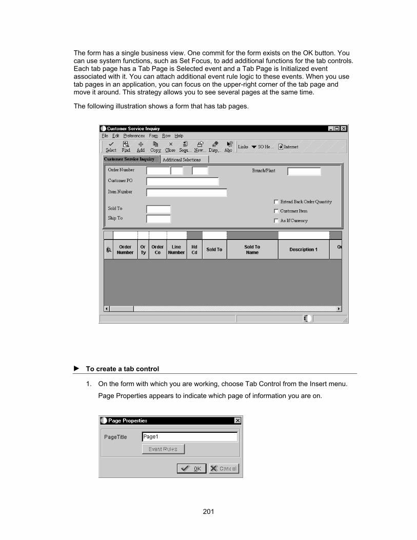
The form has a single business view. One commit for the form exists on the OK button. You can use system functions, such as Set Focus, to add additional functions for the tab controls. Each tab page has a Tab Page is Selected event and a Tab Page is Initialized event associated with it. You can attach additional event rule logic to these events. When you use tab pages in an application, you can focus on the upper-right corner of the tab page and move it around. This strategy allows you to see several pages at the same time.
The following illustration shows a form that has tab pages.
► To create a tab control
1. On the form with which you are working, choose Tab Control from the Insert menu.
Page Properties appears to indicate which page of information you are on.
201

2. On Page Properties, complete the Page Title.
Your form appears with a tab at the top.
3. Position and resize the tab.
4. On Page Properties, change the generic tab name to one that suits your needs.
202

5. After you create the initial tab control, choose Tab Page from the Insert menu to add additional tab pages as necessary.
The size of each page in the tab control is equal to the size of the entire tab control. You cannot resize an individual page to be bigger or smaller than the others.
Designing Forms Using Multiple Modes
You can use control modes to develop an application with multiple interfaces, which reduces the need to maintain several different versions of the same application. You can create one base application and use modes to modify the application for different interfaces. You can enable or hide controls on forms for each mode. Only visibility and enable/disable properties for controls, columns, and menu exits are different for different modes. If you show hidden fields, they appear only for the current mode. All other properties are the same and are common for all modes. All fields are enabled and appear all forms.
The Windows runtime engine does not recognize control modes; only the HTML runtime engine recognizes them. Mode 1 is the default mode. You attach an application to a menu to run. This menu allows you to run an application in different modes. When you run an application over the Web, the application runs in mode 1 by default and another mode, if you specify one. If you attach an application to a Windows menu, the Windows runtime engine ignores any modes that you specified and runs the application in mode 1. Use modes consistently throughout your applications. To create Web-enabled versions of your forms, you generate them in Java and HTML using the Java & HTML Generator. The generator allows you to generate forms simultaneously for one or more modes.
See Also Developing Web Applications
203

Viewing Forms in a Particular Mode
You can view the forms that you are developing in one of three modes:
• Mode 1
• Mode 2
• Mode 3
► To view forms in a particular mode
1. On Forms Design, from the View menu, choose Control Modes
2. From the mode drop-down menu that appears, choose one of the following mode options:
• Mode 1
• Mode 2
• Mode 3
The forms and controls that are particular to the mode that you chose appear.
You usually develop your applications in Mode 1 and customize them as needed for Mode 2 and Mode 3.
Setting Control Mode Properties
You can set mode properties individually for each control on a form. The default display for all modes is enabled. The mode properties allow you to enable or hide controls for each of the following modes:
• Mode 1
• Mode 2
• Mode 3
If you hide a control, it is disabled. This means that the event rules and logic for that control will not run, so be very careful when you hide controls.
► To set control mode properties
1. On the form with which you are working, right-click the control that you want to enable or hide.
2. Choose Modes from the menu that appears.
204

3. On Modes Properties, double-click the Enabled box beside one of the following modes:
• Mode 1
• Mode 2
• Mode 3
4. From the menu that appears, choose one of the following:
• Enabled
• Hidden
Controls are automatically enabled unless you change them to hidden.
Overriding Data Dictionary Triggers at Design Time
For default triggers that are defined in the data dictionary, the application to which they are attached automatically executes them at runtime. However, you can override previously-defined triggers at the application level, which allows you to further customize how data items behave at runtime.
Use the disable option to turn off data dictionary triggers for a specific item, or to override triggers to change to a new value or option.
► To override previously defined triggers
1. On the Form, Grid, Edit Control, or UDC Edit Control Properties form, click Overrides.
205

2. Click any of the following Disable options:
• Editing
• Formatting
• Default Value
• Next Numbering
• Upper Case
• Visual Assist
3. Click any of the following to override triggers that were previously defined in the data dictionary:
• CB - Default Value
• CB - Visual Assist
• Formatting
• CB - Edit Rule
206

• CB - UDC
• CB - Next Number
• CB - Styles
• CB - Display Decimals
See Also Data Dictionary for information about setting triggers in the data dictionary
Overriding a Default Value Trigger You can override a default value trigger to assign a different default value for a field or to allow no default value.
► To override a default value trigger
1. On Data Dictionary Overrides, click the Default Value button.
2. On Override Default Value, click one of the following options:
• None
• Default Value for Entry
207
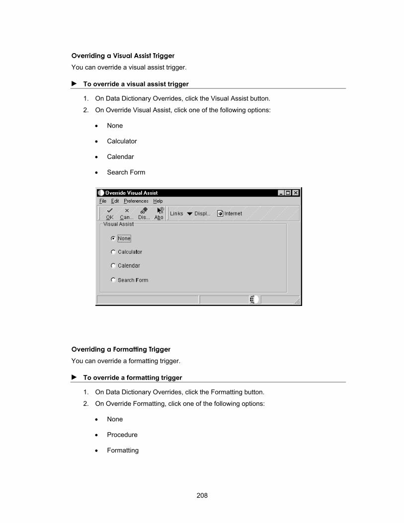
Overriding a Visual Assist Trigger You can override a visual assist trigger.
► To override a visual assist trigger
1. On Data Dictionary Overrides, click the Visual Assist button.
2. On Override Visual Assist, click one of the following options:
• None
• Calculator
• Calendar
• Search Form
Overriding a Formatting Trigger You can override a formatting trigger.
► To override a formatting trigger
1. On Data Dictionary Overrides, click the Formatting button.
2. On Override Formatting, click one of the following options:
• None
• Procedure
• Formatting
208

Overriding an Edit Rule Trigger You can override an edit rule trigger.
► To override an edit rule trigger
1. On Data Dictionary Overrides, click the Edit Rule button.
2. On Override Edit Rule, click one of the following options:
• None
• Procedure
• Edit Rule
209
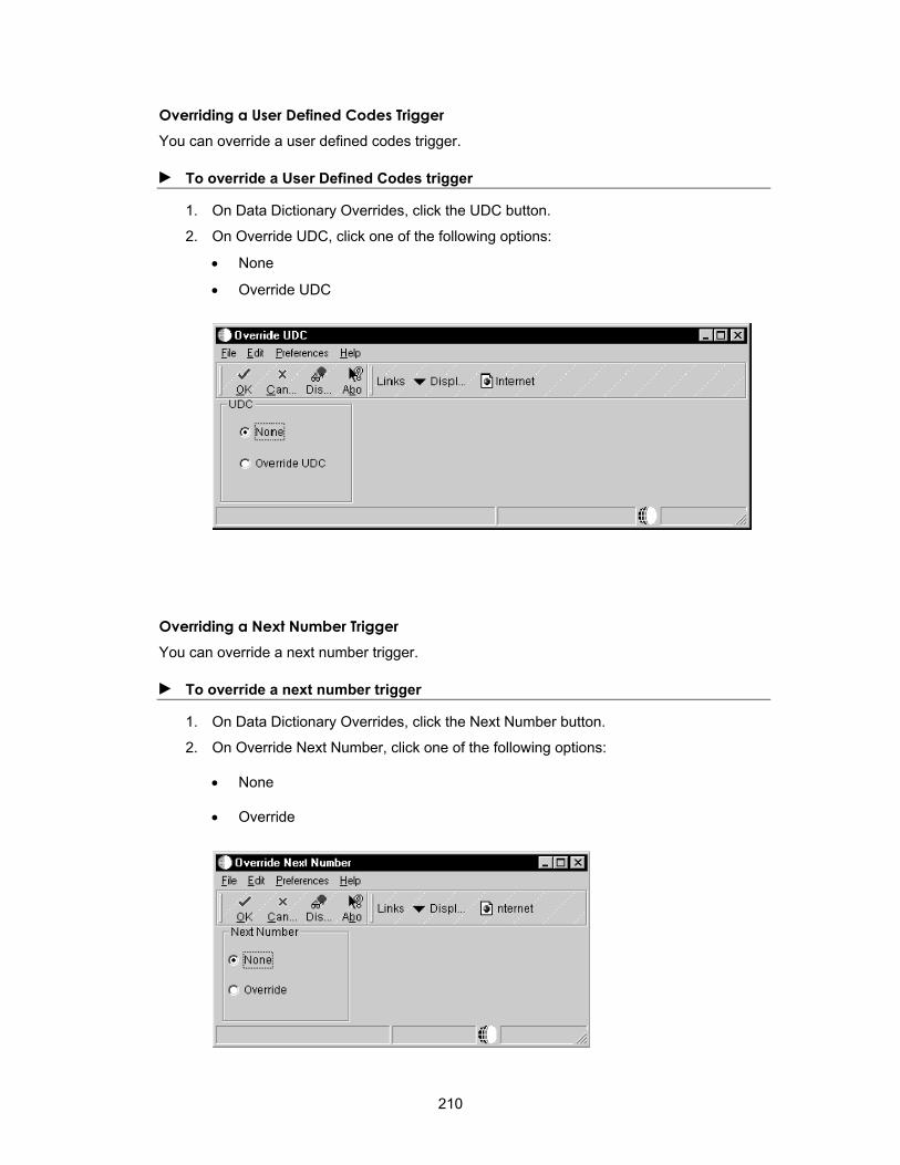
Overriding a User Defined Codes Trigger You can override a user defined codes trigger.
► To override a User Defined Codes trigger
1. On Data Dictionary Overrides, click the UDC button.
2. On Override UDC, click one of the following options:
• None
• Override UDC
Overriding a Next Number Trigger You can override a next number trigger.
► To override a next number trigger
1. On Data Dictionary Overrides, click the Next Number button.
2. On Override Next Number, click one of the following options:
• None
• Override
210

Overriding a Styles Trigger You can override a styles trigger to change the way in which information appears on a form.
► To override a styles trigger
1. On Data Dictionary Overrides, click the Styles button.
2. On Override Styles, click one of the following options:
• Allow Blank Entry (Y/N)
• Upper Case Only (Y/N)
Overriding a Decimal Trigger You can override a decimal trigger to change how decimals appear.
► To override a decimal trigger
1. On Data Dictionary Overrides, click the Decimals button.
2. On Override Display, complete the following field:
• Display Decimals
Using Text Variables
Text variables are stored as strings and can be used as an alternative to hard-coding text strings in assignments. Because text variables are not hard-coded, they are easier to maintain. Following are some of the ways in which you can use text variables:
• To reuse forms. For example, you can reuse message forms and display the appropriate message depending on specific conditions.
211
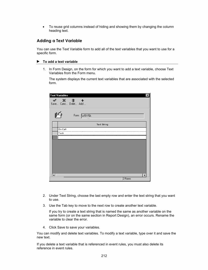
• To reuse grid columns instead of hiding and showing them by changing the column heading text.
Adding a Text Variable
You can use the Text Variable form to add all of the text variables that you want to use for a specific form.
► To add a text variable
1. In Form Design, on the form for which you want to add a text variable, choose Text Variables from the Form menu.
The system displays the current text variables that are associated with the selected form.
2. Under Text String, choose the last empty row and enter the text string that you want to use.
3. Use the Tab key to move to the next row to create another text variable.
If you try to create a text string that is named the same as another variable on the same form (or on the same section in Report Design), an error occurs. Rename the variable to clear the error.
4. Click Save to save your variables.
You can modify and delete text variables. To modify a text variable, type over it and save the new text.
If you delete a text variable that is referenced in event rules, you must also delete its reference in event rules.
212

Attaching or Assigning a Text Variable
You can use system functions to attach text variables. You can use a system function to change the text for a control, to change the name on the form, or to change the text in a grid column heading. The following system functions are typically used for text variables:
• SetControlText
• SetGridColumnHeading
• SetFormTitle
The available text variables appear in the Available Object list for System Functions. Available text variables also appear when you use assignments.
► To attach a text variable
1. To attach text to a control, on the form with which you are working, choose event rules from the Edit Menu.
2. From the events list, choose the event to which you want to attach the text variable.
3. Click the System Function button.
4. Choose the Set Control Text system function.
213

5. Complete the parameters.
See Attaching Functions for more information about attaching system functions.
214

You can also assign a text variable to the edit fields of data dictionary and business view items. See Creating Assignments.
Using Quick Form
Use Quick Form to easily place multiple database fields on a form, rather than choosing each data item individually. Choose one or more data items, and Quick Form automatically places each field on the new form simultaneously.
Depending on the number of selected fields, you might need to resize the form or move and align fields to achieve the desired layout.
► To use Quick Form
1. On Forms Design, choose Quick Form from the Form menu.
The title bar reflects the business view that is associated with the form.
2. Click the following options:
• Columns Per Row
• Vertical/Horizontal Placement
3. Choose and sort columns from the business view.
4. Click OK to place the fields on the form.
Quick Form remains open so that you can adjust the arrangement by changing the columns per row and the vertical and horizontal placement.
5. Click Close when you are finished.
Processing Media Objects Media Objects are used to link information or attachments to application transactions. For example, you can attach drawings of products to a form. You use a media object data structure to pass information between your application and the media object table.
You can use standard processing for media objects to bypass all event rules that are required to implement media objects. All of the required information is gathered for a form in Forms
215

Design Aid and does not require the entry of any event rules. Standard processing does the following:
• Allows you to implement media objects at the form level with no event rule coding required
• Standardizes how you use media objects across forms
• For any grid, places a paper clip icon on the row header if a media object is defined for that row
• For a form, places an icon in the status bar if a media object is defined for the form
• Allows you to attach documents to the form or to a row in the grid
• Allows you to double-click the paper clip icon in a row to start media objects for that row
• Allows you to click on the paper clip icon in the status bar to start media objects for the form
• If you choose not to use standard processing for a form, you can still use event rules and system functions to make media objects work.
The Media Objects Storage table (F00165) stores link records for media objects and imaging. You must define your media object data structure using a unique key structure so that the F00165 table can store data correctly. The layout of the F00165 table is as follows:
GTxxx || F4211Keys || The media object text
GTxxx is the naming convention that you use when you define a media object data structure. The F4211Keys portion is the information that the system uses to access the unique media object attachment for that particular record. These keys typically match the unique key for each detail line in the F4211 table. The media object text portion is the actual text attachment that would store information that the user typed. The F00165 table chains records for text that is greater than 30K. A sequence field indicates the order of the text and that the text is stored in two files.
The Media Object Categories table (F00166) contains a record with characterization values for each media object that has been characterized. Each record contains the characterization values for a single media object, such as a text or word document. Multiple F00166 records can exist for each F00165 record. The key is the same as that of the F00165 plus the Object ID.
The Media Object Category Constant table (F00167) contains a record that indicates which categories are used to characterize setup for each GT structure. Only one record exists for each GT structure.
The Media Object Queues table (F98MOQUE) is used for multiple OLE queues. It includes the following:
• Online/offline queue paths
• Secondary text queues
• Queue status information, such as read-only and read/write information
• Longer queue names that allow FTP access by the Java Application Server
This table allows you to include media objects in several different queues.
216

Imaging
Imaging allows you to use images from third-party software. For performance reasons, imaging occurs on a form-by-form basis. When you attach an image to a document, the media object form includes the vendor's software as a choice.
When you use a third-party vendor, the Media Object Storage table (F00165) stores the reference to image attachments, but the third-party software controls the search and retrieval of images.
Before You Begin To display the media object paper clip column on your form, turn off the Hide Row
Numbers option in the Grid properties for the form in Form Design.
Using Standard Processing for Media Objects
You can enable imaging and opens the other fields on a form.
► To use standard processing for media objects
1. On Form Design, choose Media Objects Setup from the Form menu.
2. On Media Objects Setup, click the Enable Automatic Media Object Functionality option to turn it on.
This option enables imaging and opens the other fields on the form.
217

3. Click one of the following options:
• Media Objects Only
• Document Handling Only
Use the Document Handling Only option if you are developing a form that is enabled for media objects via functionality in event rules and you want to bypass standard processing. If you want to enable standard processing later, you must delete all of the event rules for media objects and click the Media Objects & Document Handling option to turn it on.
• Media Objects & Document Handling
4. Click Edit mode or Display mode.
Edit mode allows the user to make changes, while display mode is read-only.
5. Click the Define Form Key button.
The System Functions form appears. This form is identical to the parameter definition form that you use to define system functions in Event Rules, except that it includes only the Media Objects header.
218

The key structure stores link records in the Media Objects Storage table (F00165). These links are critical to proper functioning of Imaging.
6. Double-click on the Media Object Structures folder.
A list displays all of the currently-defined data structures for Media Objects.
219
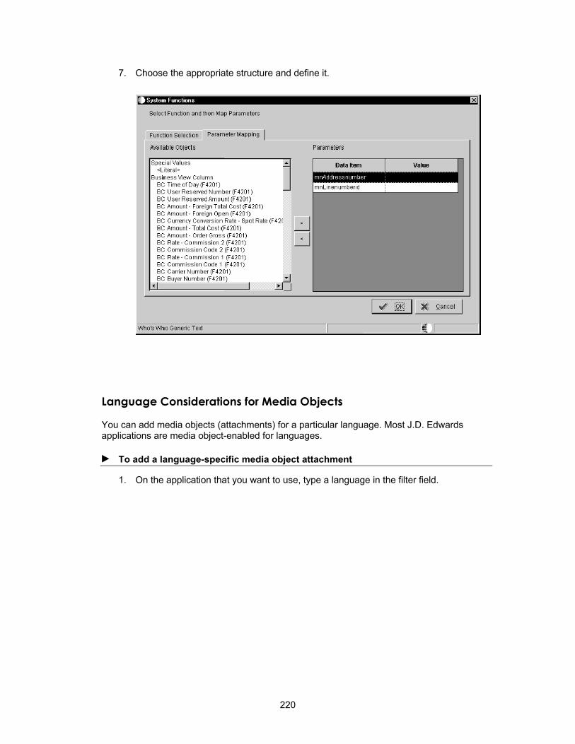
7. Choose the appropriate structure and define it.
Language Considerations for Media Objects
You can add media objects (attachments) for a particular language. Most J.D. Edwards applications are media object-enabled for languages.
► To add a language-specific media object attachment
1. On the application that you want to use, type a language in the filter field.
220

2. Click Add.
3. Add multiple records if you want the attachment for multiple languages or base.
221
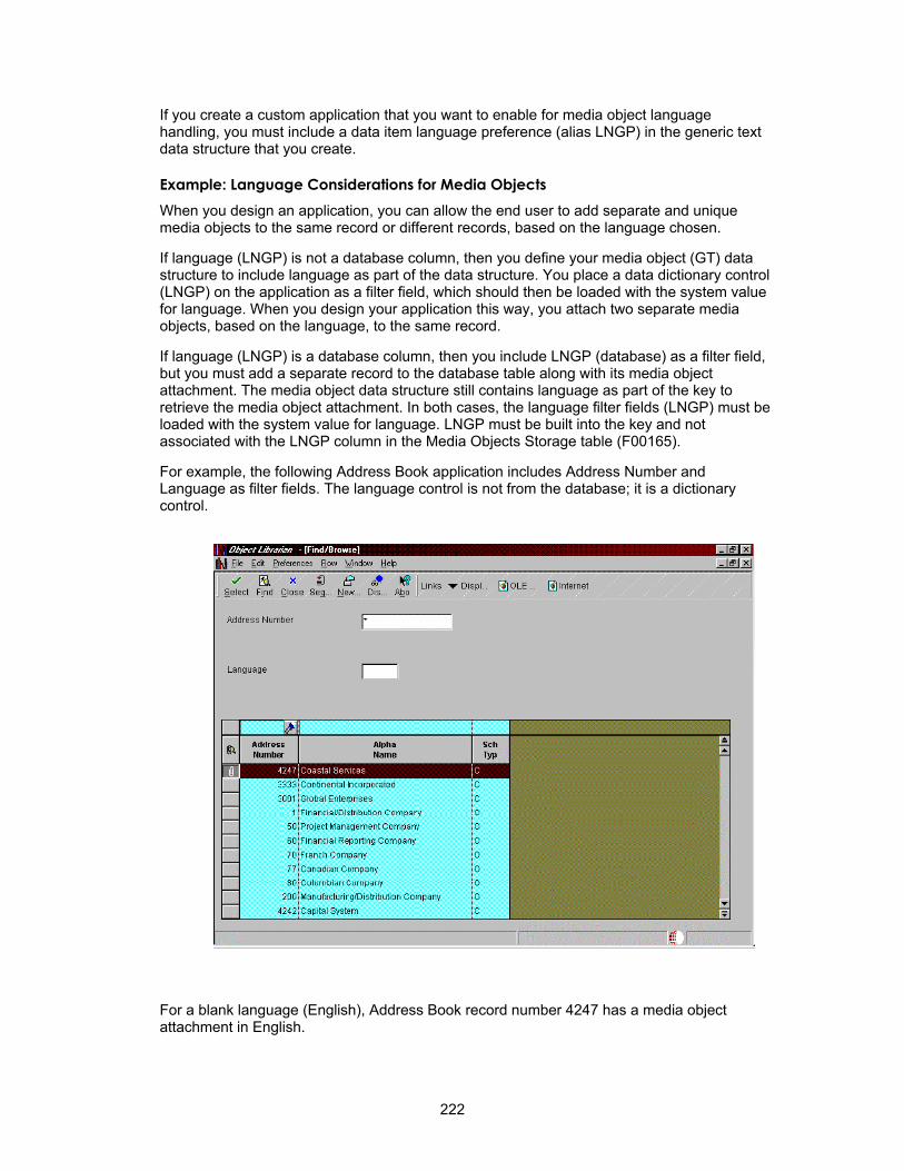
If you create a custom application that you want to enable for media object language handling, you must include a data item language preference (alias LNGP) in the generic text data structure that you create.
Example: Language Considerations for Media Objects When you design an application, you can allow the end user to add separate and unique media objects to the same record or different records, based on the language chosen.
If language (LNGP) is not a database column, then you define your media object (GT) data structure to include language as part of the data structure. You place a data dictionary control (LNGP) on the application as a filter field, which should then be loaded with the system value for language. When you design your application this way, you attach two separate media objects, based on the language, to the same record.
If language (LNGP) is a database column, then you include LNGP (database) as a filter field, but you must add a separate record to the database table along with its media object attachment. The media object data structure still contains language as part of the key to retrieve the media object attachment. In both cases, the language filter fields (LNGP) must be loaded with the system value for language. LNGP must be built into the key and not associated with the LNGP column in the Media Objects Storage table (F00165).
For example, the following Address Book application includes Address Number and Language as filter fields. The language control is not from the database; it is a dictionary control.
For a blank language (English), Address Book record number 4247 has a media object attachment in English.
222

When a user whose language preference is set to French (F) accesses the same record, the filter field does not load with F, and the user sees a different Media Object attachment for the record. The Address Book does not have two separate records based on the language, but only one record in English. For the French Media Object attachment, a separate record exists in the F00165 table for the same Address Book record. It can be accessed using the language filter control field.
In this example, the ABLNGP field and column from the Address Book table is the filter field on the form. The Language field on the form is from the database, not a data dictionary item.
223

When you search for records using blank or * (English or ALL) as the base language, you see all records in the Address Book with their corresponding media object attachments. You use the same media object data structure as you did with the previous case, which contains the Address Number and Language data items. You still load the user's language preference in the language filter field, but, when the application fetches records from the database, it uses the language as part of the key to select records from the Address Book. In this example, if no records exist in the Address Book with the language preference for French (F), you do not see any records; therefore, you must then add records using French as the language.
224
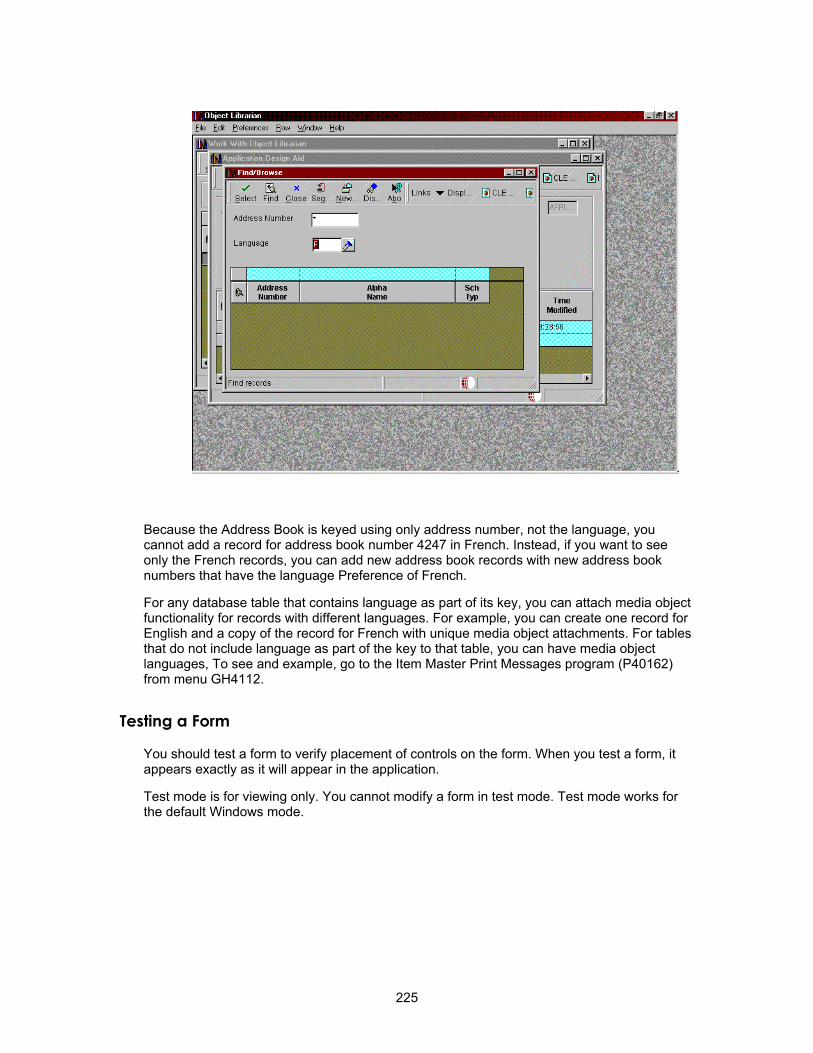
Because the Address Book is keyed using only address number, not the language, you cannot add a record for address book number 4247 in French. Instead, if you want to see only the French records, you can add new address book records with new address book numbers that have the language Preference of French.
For any database table that contains language as part of its key, you can attach media object functionality for records with different languages. For example, you can create one record for English and a copy of the record for French with unique media object attachments. For tables that do not include language as part of the key to that table, you can have media object languages, To see and example, go to the Item Master Print Messages program (P40162) from menu GH4112.
Testing a Form
You should test a form to verify placement of controls on the form. When you test a form, it appears exactly as it will appear in the application.
Test mode is for viewing only. You cannot modify a form in test mode. Test mode works for the default Windows mode.
225
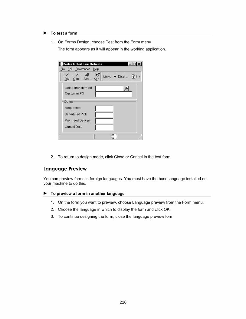
► To test a form
1. On Forms Design, choose Test from the Form menu. The form appears as it will appear in the working application.
2. To return to design mode, click Close or Cancel in the test form.
Language Preview
You can preview forms in foreign languages. You must have the base language installed on your machine to do this.
► To preview a form in another language
1. On the form you want to preview, choose Language preview from the Form menu.
2. Choose the language in which to display the form and click OK.
3. To continue designing the form, close the language preview form.
226

Event Rules
Event Rules Design
Use Event Rules Design to create business logic for an application. For example, create event rules that do the following:
• Perform a mathematical calculation
• Pass data from a field on a form to a field on another form
• Count grid rows that are populated with data
• Interconnect two forms
• Hide or display a control using a system function
• Evaluate If/While and Else conditions
• Assign a value or expression to a field
• Create variables or programmer-defined fields at runtime
• Perform a batch process upon completion of an interactive application
• Process table input and output, data validations, and record retrieval
Before You Begin Create an application with one or more forms.
Understand the difference between database items and data dictionary items.
Understand the relationship between controls, events, and event rules.
Determine the purpose of each form used in the application.
Answer the following four questions:
• What logic is required?
• For which control are you creating logic?
• For which event will the logic occur?
• Which runtime structures are affected?
Understanding Controls
A control is a reusable object that appears on a form. Examples include push buttons, edit fields, and grids. A form itself is also considered a control.
Controls can be simple or complex. Simple controls have few event points to which logic can be attached. Complex controls can have many event points to which logic can be attached.
Understanding Events
Events are activities that occur on a form, such as entering a form or exiting a field using the Tab key. Events can be initiated by the user or the application. A single control can have multiple events that it might initiate. The system also initiates some events, such as Last Grid Record Read, when certain actions occur.
227

Understanding Form Processing
Form processing refers to the business logic associated with each form. By default, each type of OneWorld form automatically includes basic processing for various events. Then, using Event Rules Design, you can build additional logic. Form processing depends on the occurrence of specific events, such as initializing a form or changing the value of a field.
See Form Processing for more information.
Understanding Event Rules
Event rules are logic statements that you can create and attach to events. They are initiated when events occur at runtime. The following illustration shows this relationship.
You can attach multiple event rules to one event.
Types of event rules include:
• If/Else/End if conditional statements
• While loops
• Assignments to statements
• Calls to encapsulated functions
• Form or report interconnections
• Calls to system functions
• Table I/O operations
OneWorld uses two types of event rules: business function event rules and embedded event rules.
Business Function Event Rules
Business function event rules are encapsulated, reusable, business logic that you create using event rules, rather than C programming. They are stored as objects and are compiled. Business function event rules are sometimes called Named Event Rules (NER).
Embedded Event Rules
Embedded event rules are specific to a particular table, interactive application, or batch application. They are not reusable. Examples include using form-to-form calls, hiding a field based on a value in a processing option, and calling a business function. Embedded event
228

rules can be in application event rules (interactive or batch) or in table event rules. They can be compiled or uncompiled.
Application Event Rules
You can add business logic that is specific to a particular application. Interactive applications connect event rules via Form Design, while batch event rules use Report Design.
Table Event Rules
You can create database triggers, or rules that you attach to a table using Table Design Event Rules. The logic that is attached to a table is executed whenever any application initiates that database event. For example, to maintain referential integrity, you might attach rules to a master table that delete all children when a parent is deleted. Any application that deletes information from that table does not need to have the parent/child logic imbedded in it because that logic exists in the table.
Refer to the online help Published API section for information about individual events.
Understanding the Event Rule Buttons
The Event Rules Design form displays the following buttons for generating different types of business logic:
Business Function Attaches an existing business function.
System Function Attaches an existing J.D. Edwards system function.
IF/While Creates an If/While conditional statement.
Assignment Creates an assignment or a complex expression.
Report Interconnect Establishes a connection to a batch application or report.
Form Interconnect Establishes a form interconnection.
Else Inserts an Else clause, which is valid only within the bounds of If and Endif.
Variable Creates a programmer-defined field, which has data dictionary characteristics for application-specific purposes, but does not reside in the data dictionary.
Table I/O Allows event rule support for database access. Performs table input and output, data validations, and record retrieval.
229

Event Rules Based on Form Type
Each form type has specific event rules that you typically use for that form type.
Form Type Event Rules Find/Browse Form-Level and Grid Level
Fix/Inspect
Header Detail and Headerless Detail Form-Level and Grid Level
Runtime Processing
Runtime processing refers to how the system evaluates at runtime events (such as initializing a form, clicking a button, and using the Tab key to move between fields) and their attached event rule logic. Event rule logic is attached to events, which, in turn, are attached to controls.
Forms Design provides several different form types, each of which includes predefined fields andfeatures that are specific to the form type. For example, the Find/Browse form automatically includes a Find menu option or toolbar button with appropriate capabilities attached to it. When you type search text in a filter field or Query by Example (QBE) field, and then click the Find button on the toolbar, the runtime engine processes logic to fetch a record .
To avoid generating unnecessary event rules, you should understand the different field types and associated capabilities that characterize each form type. You can also customize existing event rules.
Runtime Data Structures
Runtime data structures are structures or blocks of memory that hold data in memory as the system reads, processes, and writes the data to the database. You should know what is happening to each form at runtime. You should know what is in a runtime structure at a given event point.
The runtime system dynamically creates runtime data structures. For example, if a form contains hidden controls, the system allocates memory for those controls even though they are not visible on the form. When you pass processing option values in a form, the system allocates memory to store the processing option value.
Available Objects and Runtime Data Structures
An available object is represented by a two-character, alphabetical code that characterizes the source of data and determines how the object data is used in an interactive application at runtime. Available objects comprise the runtime data structure for a form.
During runtime processing, the system stores data in memory in an internal data structure. A data structure enables data to pass to another field on the same form or between forms. Certain fields of the data structure temporarily store data during runtime. When the data is no longer needed, the system deletes it so that it can process another record.
230

Available objects include following:
BC A column in the business view. Business view columns for both the form view and the grid view appear in this list. The system fills these columns with values from the database when it performs a fetch. The system saves the values to the database during an add or update.
GC A column in the grid. The row that the value references depends on which event is accessing the GC. During the fetch cycle, the system fetches the row. It is usually the selected row. In some circumstances, these objects also denote a particular physical column in the grid instead of a value, as with the Set Grid Line Font system function.
GB The grid buffer. This buffer is one row of data space that is independent of the lines that the system reads from the database and writes to the grid. The grid buffer allows you to manipulate column data for a line that you wish to insert or update without affecting the grid's present state. You access the grid buffer through the available object Grid Buffer Column (GB), which appears after the Grid Columns (GC) in the list of available objects in event rules. Each grid contains only one instance of each GB column. The grid buffer is not associated with any particular line.
FC A control on the form. If the control is a database item, this field corresponds to a BC object. Furthermore, if the control is not a filter, the FC object represents the same value as the BC object, and changing one of these results in changing both.
FI A value passed through a form interconnection. You access this object to read values that are passed into the form or to set values to be passed back. These objects correspond to the elements of the form data structure.
PO A value passed from a processing option. These values are passed into the application when a user starts it, and any form in that application can access them. Processing options can either be entered by the user, or they can be set up in a particular version of an application.
QC A column from the Query by Example (QBE) line in the grid. These objects represent the values in any QBE cell on the grid. They include wildcards, but do not include any comparison operators. Likewise, assignments to these objects can include wildcards, but not comparison operators. You can use a system function to set comparisons. QC objects do not affect the data selection on an update grid.
HC Hypercontrol item. These objects represent hypercontrol items on the form's hypercontrol. They can be used to enable and disable those items on the form menu and on the toolbar, as well as invoke them through event rules.
VA Event rules variables. These objects represent any variables that the developer set up in event rules. The system does not manipulate event rules.
SV System variables. These objects represent some environment variables that are accessible to event rules.
SL System literals. These objects represent some constant system values that are accessible to event rules.
TP Tab page object.
TK A column in the table that contains the table event rule.
CO A constant, for example the return code for an error.
TV Text variable.
RC Report constant (UBE).
231

RV Report variable (UBE).
IC Input column (table conversion).
OC Output column (table conversion).
BC and FC share the same internal structure if an FC is associated with a database item; filter fields are an exception.
Event Rule Manipulation
To automatically tailor searches to certain situations without adding filter form controls, you can assign values to QBE Columns using event rules. Unlike filters, event rules allow you to change comparison operators at runtime instead of during design time.
Processing Available Objects
When the value of an available object changes during event rule processing, the following occurs:
• The new value is copied to the business view data, grid data, form control data, form-interconnect data, or processing option data immediately after that ER line is processed (internal runtime structure).
• Form control data and grid data are copied to the appropriate form control or grid cell (external screen).
Form control data that is associated with database items share the runtime data structure with business view data. (Filter fields are an exception to this rule.) This means the following:
• FC data and BC data are always identical.
• Whenever FC runtime data is changed, any reference to BC reflects the same value.
• Whenever the BC value is changed, the FC runtime value also changes. This change in the FC is not reflected on the form until the FC runtime value moves to the screen.
• On Control is Exited processing, the value entered into the form control is captured in the runtime data structure that is shared by BC and FC.
Control is Exited Processing
Control is Exited processing includes the following:
• The value in the control is saved to the internal runtime structure(s).
• The Control is Exited event is processed.
• If the value has changed since the last time the control was exited, the following occurs:
• The Control is Exited and Changed - Inline event is processed
• The asynchronous process is launched (the next three steps are executed on a thread)
• The Control is Exited and Changed - Async event is processed
• Data Dictionary validation is processed
• The form control data is formatted and copied back to the control
232

For Fix/Inspect and Transaction forms, this logic is also performed for each control on the OK Button.
Grid Processing
You can use system functions to manipulate the selection or sequencing in a grid. These functions give you direct access to the database APIs and the selection and sequencing structures that you use when the runtime engine populates the grid. You can use the following system functions for this purpose:
Set Selection Creates one element in the select structure.
Set Lower Limit Creates one element in the select structure. This system function is similar to Set Selection.
Clear Selection Removes all system-function-defined selection information.
Set Selection Append Flag
Determines whether the system-function-defined information appends to or replaces QBE and filter field information.
Set Sequencing Creates one element in the sort structure.
c Removes all system-function-defined sequencing information.
If a Headerless Detail form contains at least one equal filter or one nonfilter database form control, the system updates the grid records for the form only if they change.
You can also use the Get Custom Grid Row event, and system functions, such as Continue Custom Data Fetch, for page-at-a-time processing for custom grids. This processing allows you to fetch only a page of data at a time to limit the number of possible records. This is particularly useful for grids in which you might be fetching thousands of records.
Grid columns have type-ahead capability. When a user enters a character in the field, the system searches a history list for a match. If a match exists, it appears in the field with highlighted text. This feature is particularly useful for data entry work because it can reduce the amount of typing required.
Form Flow
Each form type has its own properties and its own event flow. Processing occurs regardless of whether you add event rule logic. However, the engine pauses at specific events, such as Dialog Is Initialized, so that you can add logic or manipulate values. Event rule logic and user interaction determine how events execute.
Some of these events occur on each form, although the order and number of events varies depending on the form type. For example, Dialog Is Initialized is a good place to add logic on all forms. Post Dialog is Initialized is a good place to add logic on a Fix/Inspect form, but not on a Find/Browse form. For a form with an updateable grid, Dialog is Initialized and Post Dialog is Initialized mean something different than they do for a form without a grid. For forms with an updatable grid, the system performs a Find and reads the database between these two events.
For more information about the process flow for different form types, refer to Form Processing.
233
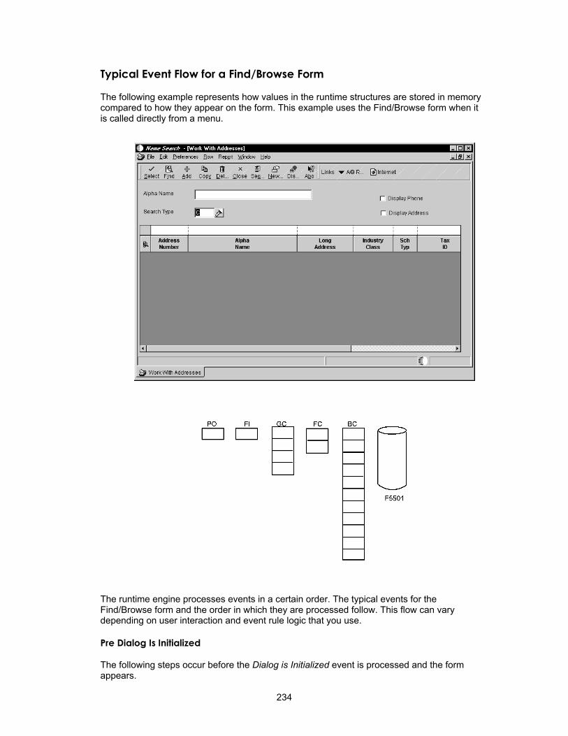
Typical Event Flow for a Find/Browse Form
The following example represents how values in the runtime structures are stored in memory compared to how they appear on the form. This example uses the Find/Browse form when it is called directly from a menu.
The runtime engine processes events in a certain order. The typical events for the Find/Browse form and the order in which they are processed follow. This flow can vary depending on user interaction and event rule logic that you use.
Pre Dialog Is Initialized
The following steps occur before the Dialog is Initialized event is processed and the form appears.
234

• Initialize runtime structures (or memory is cleared)
BC = 0
FC = 0
GC = 0
FI = Values passed from a calling form (if any)
PO = Values passed from processing options
• Initialize form controls
• Initialize error handling
• Initialize static text
• Initialize helps
• Create toolbar
• Load form interconnect data into corresponding BC columns and filter fields (if any exist)
• Initialize thread handling
• Use filter controls to build a WHERE clause of an SQL SELECT statement
If a form interconnection to the form exists, the computer memory contains information in the FI structure. The FI value is copied to the BC runtime structure.
Dialog Is Initialized
The engine pauses for the event to be processed. The system processes all event rule logic that is attached to the Dialog Is Initialized event. When the engine pauses, the runtime structures contain the following values:
BC = Any FI values passed
FC = Any FI values passed
GC = 0
FI = Values passed from a calling form (if any)
PO = Values passed from processing options
The following illustration represents the information in the runtime structures just before the system runs Dialog Is Initialized.
235
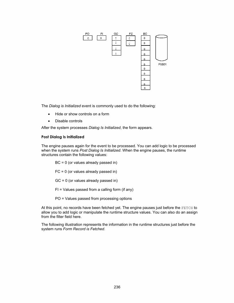
The Dialog is Initialized event is commonly used to do the following:
• Hide or show controls on a form
• Disable controls
After the system processes Dialog Is Initialized, the form appears.
Post Dialog Is Initialized
The engine pauses again for the event to be processed. You can add logic to be processed when the system runs Post Dialog Is Initialized. When the engine pauses, the runtime structures contain the following values:
BC = 0 (or values already passed in)
FC = 0 (or values already passed in)
GC = 0 (or values already passed in)
FI = Values passed from a calling form (if any)
PO = Values passed from processing options
At this point, no records have been fetched yet. The engine pauses just before the FETCH to allow you to add logic or manipulate the runtime structure values. You can also do an assign from the filter field here.
The following illustration represents the information in the runtime structures just before the system runs Form Record is Fetched.
236

The Post Dialog is Initialized event is commonly used to do the following:
• Load filter fields that will be used for the WHERE clause in the SQL SELECT statement
• Load processing option values into filter fields
• Perform any one-time logic for the form, such as fetching a system date
This event runs even when a record does not exist.
At this point, the user must click the Find button to populate the grid. (The J.D. Edwards standard is to disable autofind.) Then, the system builds the SQL SELECT.
SQL SELECT
After the user clicks the Find button, the system builds a SELECT statement with a WHERE clause. The SQL SELECT statement marks all columns in the business view.
The WHERE clause includes any values in the QBE line or in filter fields. The WHERE clause is then used to get all records that meet the QBE and filter criteria.
The following illustration represents the information that appears in the runtime structures just before the system builds the SQL SELECT and the FETCH occurs.
237
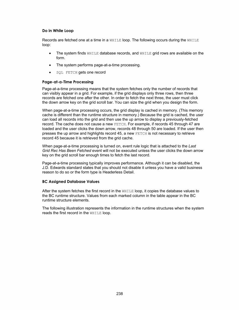
Do in While Loop
Records are fetched one at a time in a WHILE loop. The following occurs during the WHILE loop:
• The system finds WHILE database records, and WHILE grid rows are available on the form.
• The system performs page-at-a-time processing.
• SQL FETCH gets one record
Page-at-a-Time Processing Page-at-a-time processing means that the system fetches only the number of records that can visibly appear in a grid. For example, if the grid displays only three rows, then three records are fetched one after the other. In order to fetch the next three, the user must click the down arrow key on the grid scroll bar. You can size the grid when you design the form.
When page-at-a-time processing occurs, the grid display is cached in memory. (This memory cache is different than the runtime structure in memory.) Because the grid is cached, the user can load all records into the grid and then use the up arrow to display a previously-fetched record. The cache does not cause a new FETCH. For example, if records 45 through 47 are loaded and the user clicks the down arrow, records 48 through 50 are loaded. If the user then presses the up arrow and highlights record 45, a new FETCH is not necessary to retrieve record 45 because it is retrieved from the grid cache.
When page-at-a-time processing is turned on, event rule logic that is attached to the Last Grid Rec Has Been Fetched event will not be executed unless the user clicks the down arrow key on the grid scroll bar enough times to fetch the last record.
Page-at-a-time processing typically improves performance. Although it can be disabled, the J.D. Edwards standard states that you should not disable it unless you have a valid business reason to do so or the form type is Headerless Detail.
BC Assigned Database Values
After the system fetches the first record in the WHILE loop, it copies the database values to the BC runtime structure. Values from each marked column in the table appear in the BC runtime structure elements.
The following illustration represents the information in the runtime structures when the system reads the first record in the WHILE loop.
238

Grid Rec Is Fetched
The engine pauses again for the event to be processed. You can add logic to be processed when the system runs Grid Rec Is Fetched. When the engine pauses, the runtime structures have the following values:
BC = Values from the database (for the first record read)
FC = Values from the database (if database fields)
GC = 0
FI = Values passed from a calling form (if any)
PO = Values passed from processing options
The following illustration represents the information in the runtime structures just before the system runs Grid Rec Is Fetched.
239

The Grid Rec Is Fetched event is commonly used to perform the following:
• Calculate a value for a work field in the grid.
• Suppress a row from being written to the grid.
After the Grid Rec Is Fetched event (when the first record in the WHILE loop is fetched), the BC values are copied into the GC runtime structure.
The following illustration represents the information in the runtime structures when the system reads the first record in a WHILE loop.
Write Grid Line Before
The engine pauses again for the event to be processed. You can add logic to be processed when the system runs Write Grid Line Before. When the engine pauses, the runtime structures have the following values:
BC = Values from the database (from the record just read)
FC = Values from the database (if database fields)
240

GC = Values from the database (from the previous read)
FI = Values passed from a calling form (if any)
PO = Values passed from processing options
The following illustration represents the information in the runtime structures just before the system runs Write Grid Line Before.
The Write Grid Line Before event is commonly used to do the following:
• Suppress a grid row from being written
• Add logic before the user sees a row on the form
• Change formatting of a grid column
• Convert any grid value, such as unit of measure
• Retrieve additional information for the grid row, such as a description, from tables that are not in the business view.
After the system processes Write Grid Line Before, the GC elements, which now include the database values for the first record, are copied to the grid cells on the form.
The following illustration represents the information that appears in the runtime structures now.
241

Write Grid Line After
The engine pauses again for the event to be processed. You can add logic to be processed when the system runs Write Grid Line After. When the engine pauses, the runtime structures have the following values:
BC = Values from the database (from the first record read)
FC = Values from database (if database field)
GC = Values from the database (from the first record read)
FI = Values passed from a calling form (if any)
PO = Values passed from processing options
The screen grid cells display the current record.
The following illustration represents the information in the runtime structures just before the system runs Write Grid Line After.
242

You typically use the Write Grid Line After event to add logic after the user sees a row on the form.
The system reads each record in the database one at a time and passes through the same processing steps. When the system reads the next record, it performs the following processing steps:
• Performs an SQL Fetch of next record that matches criteria
• Assigns BC values from the database
• Processes Grid Rec is Fetched
• Assigns BC values to GC
• Processes Write Grid Line Before
• Displays values in the grid row on the screen
• Processes Write Grid Line After
The following illustration represents the information in the runtime structures after the system processes the Write Grid Line After event for the second record.
If the system finds grid records and the user clicks the arrow keys to fetch all records that meet the selection criteria, the SQL FETCH finally fails. If the grid is full and the user never clicks the down arrow key, FETCH might not fail because the system might not have read some of the matching records. When FETCH fails, the system processes Last Grid Rec Has Been Read.
Last Grid Rec Has Been Read
The engine pauses again for the event to be processed. You can add logic to be processed when the system runs Last Grid Rec Has Been Read. When the engine pauses, the runtime structures contain the following values:
BC = Values from the database (from the last record read)
FC = Values from the database (if database field)
GC = Values from the database (from the last record read)
FI = Values passed from a calling form (if any)
243
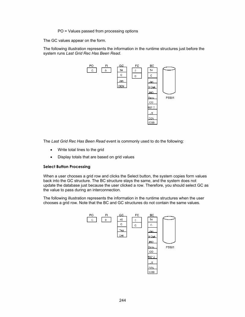
PO = Values passed from processing options
The GC values appear on the form.
The following illustration represents the information in the runtime structures just before the system runs Last Grid Rec Has Been Read.
The Last Grid Rec Has Been Read event is commonly used to do the following:
• Write total lines to the grid
• Display totals that are based on grid values
Select Button Processing
When a user chooses a grid row and clicks the Select button, the system copies form values back into the GC structure. The BC structure stays the same, and the system does not update the database just because the user clicked a row. Therefore, you should select GC as the value to pass during an interconnection.
The following illustration represents the information in the runtime structures when the user chooses a grid row. Note that the BC and GC structures do not contain the same values.
244
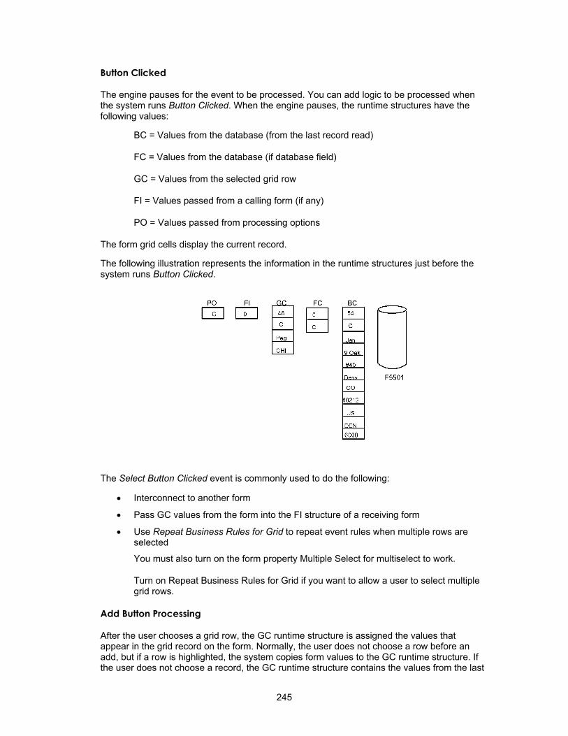
Button Clicked
The engine pauses for the event to be processed. You can add logic to be processed when the system runs Button Clicked. When the engine pauses, the runtime structures have the following values:
BC = Values from the database (from the last record read)
FC = Values from the database (if database field)
GC = Values from the selected grid row
FI = Values passed from a calling form (if any)
PO = Values passed from processing options
The form grid cells display the current record.
The following illustration represents the information in the runtime structures just before the system runs Button Clicked.
The Select Button Clicked event is commonly used to do the following:
• Interconnect to another form
• Pass GC values from the form into the FI structure of a receiving form
• Use Repeat Business Rules for Grid to repeat event rules when multiple rows are selected
You must also turn on the form property Multiple Select for multiselect to work.
Turn on Repeat Business Rules for Grid if you want to allow a user to select multiple grid rows.
Add Button Processing
After the user chooses a grid row, the GC runtime structure is assigned the values that appear in the grid record on the form. Normally, the user does not choose a row before an add, but if a row is highlighted, the system copies form values to the GC runtime structure. If the user does not choose a record, the GC runtime structure contains the values from the last
245

grid record that the system read, if any. The system does not update the database just because the user clicks the row.
The engine pauses for the Button Clicked event to be processed. You can add logic to be processed when the system runs Button Clicked. When the engine pauses, the runtime structures have the following values:
BC = Values from the database (from the last record read)
FC = Values from the database (if database field)
GC = Values from the selected grid row
FI = Values passed from a calling form (if any)
PO = Values passed from processing options
Because this is an add, the content of GC is irrelevant at this point. BC and GC do not contain the same values.
The following illustration represents the information that is in the runtime structures just before the system runs Add Button Clicked.
You typically use the Add Button Clicked event to interconnect to another form, such as a Fix/Inspect or Headerless Detail form on which the system actually performs the add.
Because you are adding a new record, you generally do not pass GC values to the FI structure of the receiving form here.
Delete Button Processing
When the user chooses a grid row, the GC runtime structure is assigned the values that appear in the grid record on the form. BC is still the same, and the system does not update the database.
The engine pauses for the Button Clicked event to be processed. You can add logic to be processed when the system runs Button Clicked. When the engine pauses, the runtime structures have the following values:
BC = Values from the database (from the last record read)
246

FC = Values from the database (if database field)
GC = Values from the selected grid row
FI = Values passed from a calling form (if any)
PO = Values passed from processing options
The following illustration represents the information in the runtime structures just before the system runs Button Clicked.
Next, the Delete Grid Rec Verify Before event occurs.
Delete Grid Rec Verify Before The engine pauses for the Delete Grid Rec Verify Before event to be processed. You can add logic to be processed when the system runs Delete Grid Rec Verify Before. The system processes the logic that is attached to this event after the user clicks Delete, but before the pop-up Verify window appears.
Next, the Delete Grid Rec Verify After event occurs.
247

Delete Grid Rec Verify After The engine pauses for the Delete Grid Rec Verify After event to be processed. You can add logic to be processed when the system runs Delete Grid Rec Verify After.
You might want to perform editing to verify that the delete is valid. For example, other tables might contain dependant records that that prevent this record from being deleted as long as they exist.
The engine pauses for the Delete Grid Rec Verify Before event to be processed. You can add logic to be processed when the system runs Delete Grid Rec Verify Before.
The system processes the logic that is attached to this event after the user clicks OK in the Verify confirmation window. If the user clicks Cancel in the Verify confirmation window, the logic attached to this event will not occur.
Next, the Delete Grid Rec From DB Before event occurs.
Delete Grid Rec From DB Before The engine pauses again for the Delete Grid Rec From DB Before event to be processed. You can add logic to be processed when the system runs Delete Grid Rec From DB Before. When the engine pauses, the runtime structures FC is blank.
The system processes the logic that is attached to the Delete Grid Rec From DB Before event after the user clicks OK to delete a record and after it processes the Verify window, but before it actually deletes the record.
You can use the Suppress Delete system function with the Delete Grid Rec From DB Before event to turn off the automatic tool delete and perform the delete yourself. For example, you can use a business function to perform the delete.
After the system processes the Delete Grid Rec From DB Before event, it builds an SQL DELETE statement. The engine pauses again so that you can add logic to process. FC is blank. The SQL DELETE occurs at this point, and the system deletes the current record from the database. When you choose multiple records, one delete call can delete all of the records.
Delete Grid Rec From DB After The engine pauses again for the Delete Grid Rec From DB After event to be processed. You can add logic to be processed when the system runs the Delete Grid Rec From DB After. This logic runs after the system physically deletes the record from the database.
The system processes the logic that is attached to the Delete Grid Rec From DB After event after the user clicks OK to delete the record and after the system processes the Verify window and actually deletes the record.
You might use this event to call a business function to delete information from related tables that are not in the business view.
All Grid Recs Deleted From DB The engine pauses again for the All Grid Recs Deleted from DB event to be processed. You can add logic to be processed when the system runs All Grid Recs Deleted from DB. At this point, FC is blank.
You can also add logic after the system physically deletes the record from the database. The system processes logic that is attached to the All Grid Recs Deleted from DB event after it deletes multiple grid lines and the corresponding database records. Rules that are attached to this event are not apparent on the screen and cannot manipulate the grid lines or records.
248

Working with Event Rules Design
You can use Event Rules Design to create event rule logic for controls on a form.
For example, suppose that you want to pass data for a selected record on a Find/Browse form to a Fix/Inspect form to make revisions to that record. To accomplish this task, you would create a form interconnect event rule and attach it to the Select toolbar option for the Button Clicked event.
Before you create an event rule, consider the control (form, button, field, grid, and so on) and the event upon which the event rule should process. Answering the following questions will determine under which of the following conditions should logic occur.
• Initializing the form?
• Clicking a button?
• Exiting field?
• Changing or exiting from a row?
See Also Understanding the HTML Client for information about turning on and off HTML post
(refresh) for an event
Creating and Saving Event Rules
After you place controls on a form, you must create event rule logic to cause processing to occur within your application at runtime. Remember, a form is also a control, and you can create logic that automatically processes whenever a form is initialized.
Create event rules by clicking the buttons on the toolbar in Event Rules Design. Depending on the button that you click, a different work area appears for creating and manipulating the event rule line by line.
Click a specific button within Event Rules Design to do the following:
• Attach a business function
• Attach a system function
• Create an If/While statement
• Assign a value or expression
• Create a form interconnection
• Create a report interconnection
• Insert an Else clause in an If statement
• Create a variable
• Perform table I/O
► To create and save an event rule
1. On Forms Design, choose a control on the form.
2. From the Edit menu, choose Event Rules.
249

3. Choose an event from the Events list box.
4. Click one of the following Event Rules buttons to add logic for the control:
• Business Function
• System Function
• If/While
• Assign
• Forms
• Reports
• Else
• Variables
• Table I/O
5. Click the following buttons to add a note, enable or disable a specific line within the event rule, or delete a specific line within the event rule:
• Comment
• Enable/Disable
• Delete
The Enable/Disable button affects only a specific line within the event rule. To disable the entire event, select the Disable Event option from the Options menu.
250
You can disable a specific line within an event rule when you want to test your event rule logic. When you are confident that a line is no longer needed, you can delete it from the event rule.
To enable, disable, or delete multiple consecutive lines, hold down the shift key and select all event rules that you want to enable, disable, or delete. After you select the desired lines, click the Enable/Disable or Delete button.
6. Click Save to save the event rule.
7. Click OK to return to Forms Design.
Saving the event rule saves it with the application. If you delete the application, or if you cancel the application before you save it, the event rule is deleted also.
Finding Event Rules
You can search for strings in event rules.
► To find a string of text in an event rule
1. From Event Rules Design, choose Find from the Edit menu.
2. Indicate the direction in which you want to search.
3. Type the string of text that you want to find and click the Find Next button.
Cutting, Copying, and Pasting Event Rules
You can cut or copy event rules and paste them in the same event, form, or application or in a different event, form, or application.
You can also paste event rules into other applications, such as word processing documents. This feature is useful for documentation purposes.
251
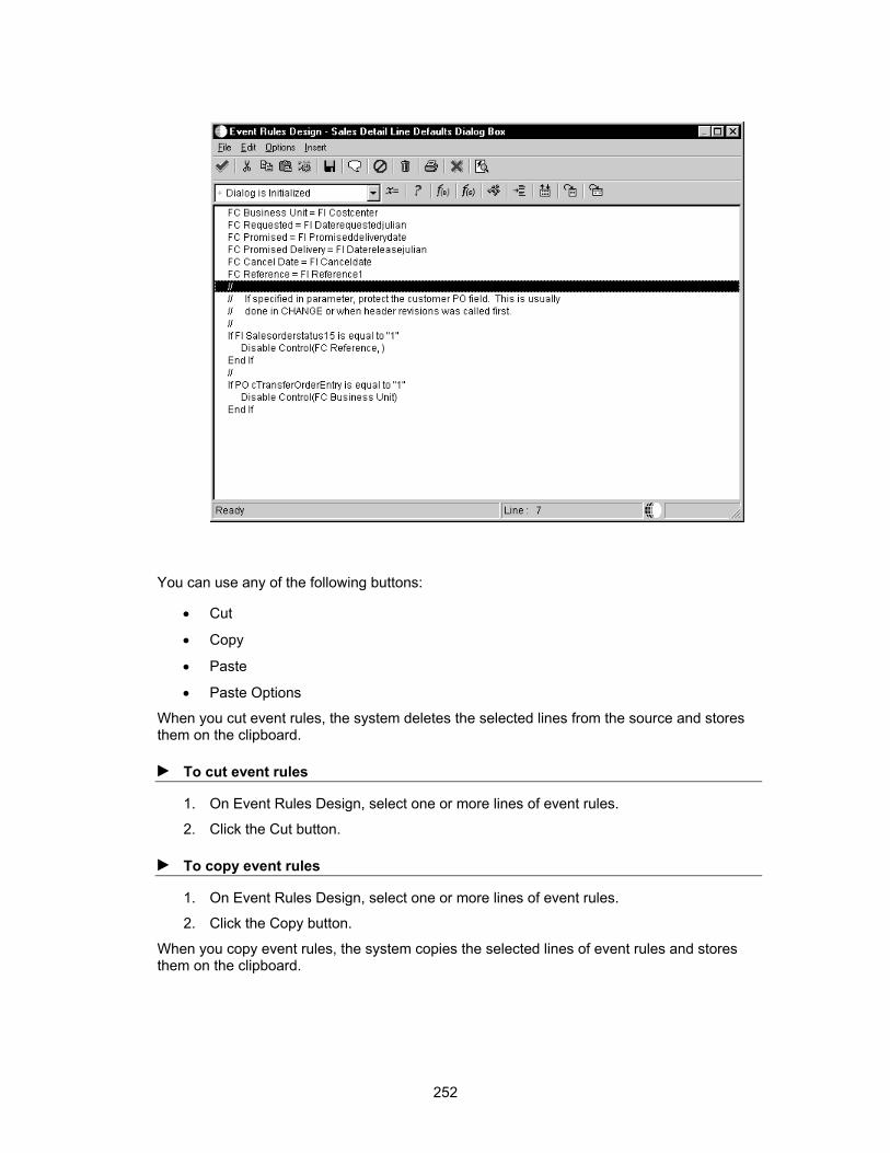
You can use any of the following buttons:
• Cut
• Copy
• Paste
• Paste Options
When you cut event rules, the system deletes the selected lines from the source and stores them on the clipboard.
► To cut event rules
1. On Event Rules Design, select one or more lines of event rules.
2. Click the Cut button.
► To copy event rules
1. On Event Rules Design, select one or more lines of event rules.
2. Click the Copy button.
When you copy event rules, the system copies the selected lines of event rules and stores them on the clipboard.
252

► To paste event rules
1. On Event Rules Design, select the line after which you wish to insert your lines of event rules.
2. Click the Paste button.
When you paste event rules, the system resolves objects from the source as you past them. If an object is partially resolved, the system pastes the closest matching object from the destination event rules. A comment line appears above the partially-resolved line of event rules and in the status bar to indicate that the object is partially resolved.
Some objects cannot be resolved in the destination event rules. The system disables these lines of event rules and displays a comment. For example, an EndIf statement is commented out if its associated If statement is missing.
For criteria statements, the paste operation adds whatever is necessary to maintain a clean, logical structure. For example, if you paste an If statement and no EndIf statement exists, the paste operation adds a matching EndIf statement to make the logic complete.
You can set paste options to display comments before and after a block of pasted event rules.
► To set paste options
1. Click the Paste Options button.
2. On Cut Copy Paste Options, click the Paste Options option.
3. Enter the number of lines for which you want comments to appear.
253
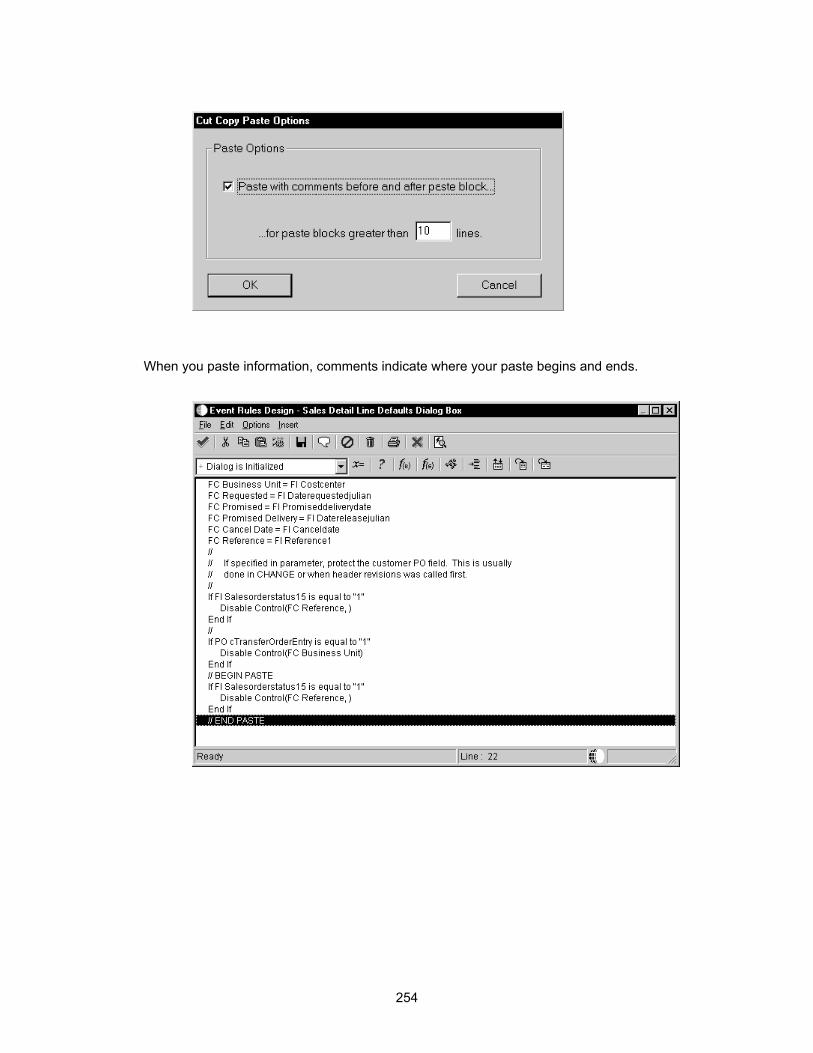
When you paste information, comments indicate where your paste begins and ends.
254

Adding Comment Lines to Event Rules
You can add a comment line to document event rule code.
► To add a comment line to an event rule
1. On Event Rules Design, position the cursor where you want to add a comment.
2. Click the Comment button.
3. Type a comment in the input area and click OK.
The system automatically formats the comment in Visual C++ notation so that you do not have to type the // to indicate that it is a comment.
255

Printing Event Rule Logic
You can print the code for event rules. This is especially useful when many lines of code comprise an event rule. You can print event rule code for the following:
• An entire application
• A form
• A control
• A single event
► To print event rule code
1. On Form Design, click the control for which you want to print event rule code.
2. From the Edit menu, choose Event Rules.
3. On Event Rules Design, choose an event from the Events list box.
The event rule appears in the work area.
4. From the File menu, choose Print.
5. On Event Rule Printing, click one of the following destinations:
• Printer
• File
6. Choose one of the following print scopes:
• Application
• Form
• Control
• Event
7. Choose one of the following page break options:
• Application
• Form
• Control
• Event
8. Choose one or more of the following print ER options:
• Expand argument
• Date/Time Stamp
• Show Line Numbers
• Show Comments
256

Validating Event Rules
You validate event rules to help you find errors, such as a variable or business function that no longer exists or an incorrect business view column. You can validate event rules either as you are working or when you save an application.
The system validates event rules either when you select Save or when you select Exit and save before exiting. You can exit Forms Design Aid or leave it open if the system finds errors during validation upon exit.
• If you select Validate Event Rules Now, the system immediately validates event rules.
► To validate event rules
1. On Forms Design, from the Application menu select the following option:
• Validate Event Rules Now
The Validate Event Rules form displays messages as it processes. When the validation successfully completes, a Generation Successful message appears.
The following example illustrates the message that appears on the Validate Event Rules form when the system finds an error.
257

Validate Event Rules checks for errors at two levels. The first level is in Business Function event rules or Table event rules in which system converts the event rule code from the event rule scripting language to C code and then to compiled code. The second level is in the application in which the system reviews the event rules for errors such as data type mismatches, data structure errors, and missing variables and controls. The Generator does not check logic errors or syntax.
The error log that the system creates is stored in a file such as b7\prod\log\p1234.log (where prod is your environment). If no errors exist, the system does not generate a log.
258

Working with If and While Statements
If and While statements are conditional instructions for an event rule. They evaluate conditions when the event rule is activated and dictate the flow of logic.
If Statements An If statement executes conditional event rule logic. That is, the logic executes only if the condition is true. The system evaluates an If statement only once when it executes the event rule.
An If statement takes this general form:
IF condition X is true
Do Y
ELSE
Do Z
ENDIF
An If statement is evaluated as follows:
If condition X is true, then do Y and stop evaluating the statement. If condition X is not true, then go to the Else clause and do Z.
The Else clause is optional. When there is no Else clause, the If proceeds to the next statement and evaluates it.
259

The following is an example of an If statement from Sales Order Entry:
While Statements A While statement repeats conditional event rule logic. That is, the logic continuously executes as long as a condition is true. A While statement controls the execution of a loop, or repetitive test.
A While statement takes this general form:
WHILE condition X is true
Do Y
ENDWHILE
The system evaluates a While statement in the following manner:
Evaluate condition X. If it is true, then do Y. Repeat evaluation of condition X until it becomes false, then exit the loop.
Creating If and While Statements
Use the If/While button to build conditional logic into an event. When you create an If statement, the system also automatically inserts an Else clause. However, you can use the Delete button to delete the Else clause and then reinsert it using the Insert Else button. When you delete an If or While statement, the system also deletes the associated Else and Endif or Endwhile clauses, but not the rules inside of those statements.
260

You can drag and drop statements on a line-by line basis to change their sequence. Resequencing event rules can result in improper syntax. When you click the Save button or the OK button, the system verifies the syntax. If it detects syntax errors, you can either disable the event rule and continue or edit the event rule to eliminate the errors.
Is Equal To and Is Not Equal To are the only valid logical operators when you use range and list values. The criteria design tool prevents you from using the range and list literals incorrectly by ensuring that the comparison is either equal to or not equal to. If you choose Range or List and your comparison field does not contain an Is Equal To or Is Not Equal To comparison, then the cell is cleared.
To change a statement, click the cell to select the cell or value that you want to change. You can then change the value of that cell. The system checks the syntax when you click OK. To move a line (resequence), select the entire row by clicking the row header. Then, use the up and down arrows on the toolbar to move that line. You cannot move the If/While line.
To delete a statement, select the line of the statement, and then click Delete. You cannot delete the top-most clause of the statement (If or While) in If/While design; you can only delete it from the Event Rules Design window.
► To create an If or a While statement
1. On Event Rules Design, select an event in the Event Rules Design window.
2. Click the If/While button.
Each cell in the Criteria Design grid represents a component of the criteria. When you select a cell by clicking on it or using the Tab key to move into it, a list of valid options appears. To select an option, either double-click it or select it, and press Enter or Tab. You can select an option by using the mouse or by typing the option that you want to select.
Criteria Design has a type-ahead feature that allows you to type the first few characters of an item in a field to automatically display a list of available items that begin with those letters.
3. Choose one of the following operators:
• If
• While
261

4. Choose a left operand from the list of available data items.
You can right-click to sort the available data items by name or object type. If only one type exists, the sort options are not available.
You can group the available data items by the following object types:
BC A column in the business view for this form
GC A column in the grid for this form
FI A value passed through form interconnection to this form
FC A control on this form, such as a push button
PO A value from processing options of the application
HC A hypercontrol
SV A system variable
SL A system value
VA A variable
5. Choose one of the following comparisons from the list of logical operators:
• Is equal to
• Is not equal to
• Is less than
• Is less than or equal to
• Is greater than
• Is greater than or equal to
6. Choose a right operand from the object list.
7. To assign a literal, select <Literal>.
The Literal dialog depends on the data item.
See Defining Literal Values in Event Rule Logic for detailed instructions for assigning a literal.
262

8. Click save to save the criterion statement and return to the Event Rules Design window.
If the criteria are incomplete (for example, if you are missing the right operand), you must fix the criteria or delete it.
You can select the And or Or option to continue your logic to create complex If statements.
Defining Literal Values in Event Rule Logic
You can define literal values in event rules.
► To define literal values
1. On Criteria Design, from the Right operand list, double-click on <Literal>.
2. Click on one of the following tabs:
263
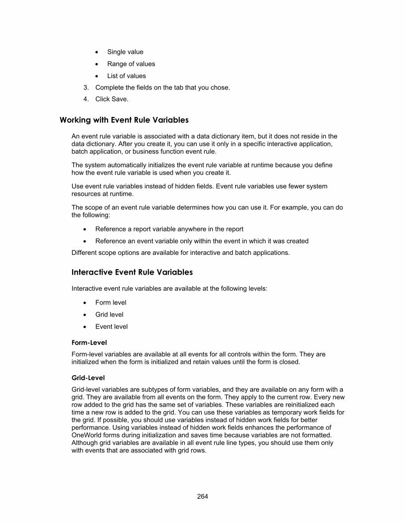
• Single value
• Range of values
• List of values
3. Complete the fields on the tab that you chose.
4. Click Save.
Working with Event Rule Variables
An event rule variable is associated with a data dictionary item, but it does not reside in the data dictionary. After you create it, you can use it only in a specific interactive application, batch application, or business function event rule.
The system automatically initializes the event rule variable at runtime because you define how the event rule variable is used when you create it.
Use event rule variables instead of hidden fields. Event rule variables use fewer system resources at runtime.
The scope of an event rule variable determines how you can use it. For example, you can do the following:
• Reference a report variable anywhere in the report
• Reference an event variable only within the event in which it was created
Different scope options are available for interactive and batch applications.
Interactive Event Rule Variables
Interactive event rule variables are available at the following levels:
• Form level
• Grid level
• Event level
Form-Level Form-level variables are available at all events for all controls within the form. They are initialized when the form is initialized and retain values until the form is closed.
Grid-Level Grid-level variables are subtypes of form variables, and they are available on any form with a grid. They are available from all events on the form. They apply to the current row. Every new row added to the grid has the same set of variables. These variables are reinitialized each time a new row is added to the grid. You can use these variables as temporary work fields for the grid. If possible, you should use variables instead of hidden work fields for better performance. Using variables instead of hidden work fields enhances the performance of OneWorld forms during initialization and saves time because variables are not formatted. Although grid variables are available in all event rule line types, you should use them only with events that are associated with grid rows.
264

Event-Level An event-level variable is available only within the event for the form control where it was added. The variable is reinitialized each time the event is processed for the form control.
Batch Application Event Rule Variables
Batch event rule variables are available at the following levels:
• Report
• Section
• Event
Creating an Event Rule Variable
After you create an event rule variable, it appears in the available objects list in Event Rules Design where you added it. Use it in event rules just as you would use any available object in the list. If you create an event level variable and do not use it in event rules, Form Design Aid automatically deletes it.
After you add an event rule variable, you cannot be modify it. However, you can delete it.
The system automatically assigns variables one of the following prefixes, based on the specified scope:
• frm_ (Form)
• evt_ (Event)
• grd_ (Grid)
• rpt_ (Report)
• sec_ (Section)
► To create an event rule variable
1. On Event Rules Design, click the Variables button.
The Variables form displays different scope options, depending on whether you are working with an interactive application, batch application, or business function event rule.
265

2. Complete the variable naming field.
Event Rule variables are named similar to C variables and should be formatted as follows: xxx_yyzzzzzz_AAAA, where:
xxx = A prefix that OneWorld automatically assigns, depending on the scope. Examples include:
frm_ (form scope)
evt_ (event scope)
y = Hungarian Notation for the following C variables:
c - Character
h - handle request
mn - Math Numeric
sz - String
jd - Julian Date
id - Pointer
zzzzzz = A variable name that you assign; capitalize each word
266

AAAA = A data dictionary alias (all upper case)
For example, a branch/plant event rule variable would be evt_szBranchPlant_MCU. Do not include any spaces.
3. Click one of the following Scope options, depending on the purpose for which you created the variable:
• Form
• Event
4. Turn on the Grid option if you select Form Scope and you want to use a grid variable.
5. Click the data dictionary visual assist to browse data dictionary items.
267

6. Click the Show All button to display the variable list.
268
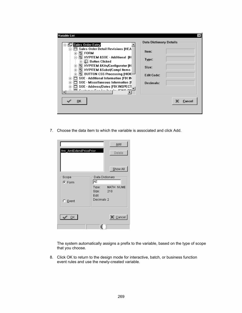
7. Choose the data item to which the variable is associated and click Add.
The system automatically assigns a prefix to the variable, based on the type of scope that you choose.
8. Click OK to return to the design mode for interactive, batch, or business function event rules and use the newly-created variable.
269

Using Event Rule Variables for Automatic Line Numbering
You can use event rules to create automatic line numbering.
► To enable automatic line numbering event rules
1. Create a variable to hold the value of the line number. Use the data dictionary item LNID.
VA frm_LineNumberCounter_LNID
2. Initialize the variable on the Post Dialog is Initialized event. VA frm_LineNumberCounter_LNID = 0
3. On the Grid Record is Fetched event, number the lines as each line is pulled from the database.
If BCLineNumber > VA frm_LineNUmber_LNID
VA frm_LineNumberCounter_LNID = BC LineNumber
End If
4. On the Add Last Entry Row to Grid event, increment the LineNumber and assign the new value to the next available line.
VA frm_LineNumberCounter_LNID = VA frm_LineNumberCounter_LNID + 1
GC LineNumber = VA frm_LineNumberCounter_LNID
Attaching a System Function to an Event
You can use the System Function button to attach predefined J.D. Edwards system functions to events. For example, you can attach system functions to an event that can do the following:
• Hide or display a control
• Insert dates
• Display media objects
► To attach a System Function
1. On Event Rules Design, choose an event.
2. Click the f(S) button.
3. Choose a category in the System Functions box.
270

4. Choose the system function that you want to attach.
5. In the Available Objects list, choose objects to pass to the system function.
271

6. Click OK to add the system function to the event rule.
Common System Functions
Clear Edit Control Error
Following are some available system functions and reasons why you might use them. Refer to System Functions in the Online APIs for more information about different system functions.
Control System Functions
Use this function to clear errors that have been set for a specific control. This is important because the runtime engine automatically sets and clears errors on specific events, but does not clear errors on other events. For example, if you use Set Edit Control Error on Dialog is Initialized, that event cannot run again to reset the error and then re-edit the control. In this situation, you can use Clear Edit Control Error to clear the error on another event. For more information on how the runtime engine sets and clears errors, see Messaging.
Disable Control
Use this system function to dynamically enable or disable a control; otherwise, use the control property. You can use this system function to disable certain fields that you do not want a user to change, such as the exchange rate on a transaction.
Enable Control
Use this system function to enable a control. For example, you can use this function when you want only a manager to have the authority to change something.
Hide Control
Use this system function to dynamically hide and show a control. You can hide a field until the user specifically requests the information it holds. For example, when you add a record in Address Book, you can display the previously-added record.
Set Edit Control Error
Use this system function to set an error on a specific control and turn the field red.
Set Status Bar Text
Use this system function to display text in the status bar. This text might describe why an error has occurred and to clear the status bar after an error has been corrected You can also
272

error has occurred and to clear the status bar after an error has been corrected. You can also use this system function when a process is running in the background or takes some time to complete. In this case, you might want to display a "Please Wait ..." message.
Was Value Entered
Use this system function to verify that data has been changed, such as when an error occurs and the information changes. One of the options for this system function is an All Controls value that determines whether any of the controls have changed. This function is useful in transaction-type programs.
Set Edit Control Color and Set Edit Control Error are two control system functions that J.D. Edwards standards prohibit you from using. Set Edit Control Color makes mandatory fields a specific color. If you use this system function, be aware that some users might be color blind. Set Edit Control Font draws attention to a field, such as a negative number, but nonstandard fonts might confuse the user or detract from the appearance of your form.
Message System Functions
Mail Send Message
Use this function to return a message ID (serial number) that is the identifier for the message that you created. This is the key parameter for the other messaging functions, and the application uses this ID to perform the other system functions. You might use this function to generate a message to a manager that requests approval for a client to exceed an authorized credit limit.
Forward Message
Use this function to forward a message. You can choose to leave the original message intact when you forward it.
Mail Delete Message
Use this function to delete a mail message.
Update Message
Use this function to modify a message with new text. You can then use Forward Message to send the new message.
General System Functions
Copy Currency Information
Use this function to ensure that, when you change currency information, the system copies the change to all of the applications that use it. This function is useful if you are developing software in a country in which the decimal place changes frequently. You can also use it when a company changes from the base of one currency to another.
Press Button Use this function to reuse event rules from event to event without having to write and maintain the code in all of the places in which you use these event rules. To do this, create a push button on a form, and put all of the reusable event rules on the button clicked event. Then, use this system function to press the button and run the ER from all of the other events in which you want to run the ER.
Set Control Focus
Use this function to set focus on a specific spot. For example, you might set focus on the detail part of the grid when a user enters a form. You can also use this function to override the default cursor position, particularly if the focus differs for and add and a change.
Stop Processing
Use this function to stop processing, such as when an error occurs.
Suppress Add Use this function to control the normal flow of the form for I/O purposes. For example, in a transaction entry programs that use master business functions, the master business function does all of the I/O, including adds.
Suppress Delete
Use this function to control the normal flow of the form for I/O purposes. For example, many J.D. Edwards transactions, such as Accounts Receivable and Sales Order, use master business functions to insure referential integrity. You might use this function to
273

prevent a user from deleting a customer's address book record that is used on existing invoices.
Suppress Find Use this function to suppress a find. For example, on updateable grid forms that can use filter and find buttons, you would probably suppress the find button if the user has not finished the current record. For those forms that do inquiries, you can verify that the user has provided information that matches an index.
Suppress Update
Use this function to suppress an update. This function can control the normal flow of the form for I/O purposes.
Was Form Record Fetched
Use this function to ensure that a record was actually fetched.
Grid System Functions
Clear Grid Buffer
Use this function to clear the buffer. Because the grid buffer is a temporary location in which to manipulate grid rows, use this system function to clear all columns in the buffer. For example, you can use the grid buffer to hold temporary values for a calculation, and then use Clear Grid Buffer to clear the buffer after the calculation completes.
Clear Grid Cell Error
Use this function in the same way that you use Clear Grid Buffer.
Clear QBE Column
This function is similar to Clear Grid Buffer. For example, you might use this function when the QBE column had a value forced into it, such as the current date on a purchase order Find/Browse form. Then, after the user performs a Find, you could clear the QBE column in case you need to use another date.
Copy Grid Row to Grid Buffer
Use this function after Clear Grid Buffer was issued and you needed to manipulate just a few of the grid columns. You can use this system function to move all of the GC fields to GB without copying each individual column.
Delete Grid Row
Use this function if you, not the runtime engine, are manipulating the grid row. For example, use this function when you are using the Delete Doc routine from the master business function.
Disable Grid Use this function to disable the entire grid from input. Use this function when you need to complete more information in the header before you can add individual rows, or to use information in the header as default information in the grid.
Enable Grid Use this function to enable the grid.
Get Grid Row Use this function to specifically read a grid row, such as when you need to reprocess the grid through a While loop.
Get Max Grid Rows
Use this function to determine how many rows must process if you need to reprocess all of the individual grid rows through a While loop. Use this function immediately before the While loop.
Get Selected Grid Row Count
Use this function to get the row number for a selected row. Typically, you use this function only when you need to save the row as a variable for future processing.
Hide Grid Column
Use this function for dynamic processing.
Hide Grid Row Use this function to hide an entire row from appearing on the form. For example, if you create a form with a grid and you want to summarize rows, add together several rows to determine a total and show the total row. If you use this system function, you might
274
include a check box for the detail information and then unhide the row instead of repopulating the grid.
Insert Grid Buffer Row
Use this function to manipulate the buffer space. If you use this system function, GC becomes GB.
Insert Grid Row
Use this function to insert a row in the grid. Usually, these rows are custom (nondatabase), such as a totaling row.
Set Grid Cell Error
Use this function in the same way that you use Set Edit Control Error.
Set Grid Color Use this function in the same way that you use Set Edit Control Color.
Set Grid Font Use this function in the same way that you use Set Edit Control Fonts.
Set Grid Row Bitmap
Use this function to manipulate the bitmap that appears outside of the grid. This function sets a specific bitmap on a specified row header.
Set QBE Column Compare Style
Use this function for complex assignments to the QBE runtime structure. For example, if you want to assign the date January 1, 2005 to a particular QBE column, you use QC=010198. Because several valid comparisons exist for the QBE line, to make the date > January 1, you must use this system function.
Show Grid Column
Use this function in the same way that you use Show Edit Control.
Suppress Grid Line
Use this function to prevent a row from becoming part of the grid. For example, use this system function on the Write Grid Line Before event to prevent the line from being written to the grid.
Update Grid Buffer Row
After the grid buffer is assigned, use this system function to make GC=GB.
Telephony System Functions You can use telephony system functions to integrate telephone communications with your applications. The telephony system functions allow you to send requests to the Microsoft Windows Telephony Application Programming Interface (TAPI). For example, you might use this capability in a customer service organization that customers call for support. When a customer calls, you can use your application to identify who is calling and automatically retrieve information about the caller.
You can use TAPI to do things such as:
• Answer an incoming call either from a direct line, PBX, or Voice Response Unit (VRU)
To answer an incoming call, you add event rules at the point in which the phone rings, but before the user picks up the receiver, and again immediately after the user picks up the receiver.
• Transfer a call
To transfer a call, determine whether the user has requested a transfer, and then add event rules immediately before the request to transfer the call and immediately after the application receives notice that the call has been transferred.
• Put a call on hold
275
To put a call on hold, you add event rules immediately after the application has received notice that the call has been put on hold and immediately after the user has picked up the call that was on hold. The user must be able to see information about all calls that are on hold.
• Place an outgoing call
To place an outgoing call, you must pass the phone number being called to the OneWorld telephony system function, which then uses TAPI to complete the steps necessary to make the call. You add event rules immediately before the call is placed, after the call is answered, and immediately after the call has ended.
• End a call
Calls can end in several ways, including when the service representative or the caller hangs up, the representative transfers the call, or the system disconnects the call because of bad phone connections. To properly close the call, you add event rules at the point in which the application receives a message that the call has ended.
Attaching a Business Function to an Event
Use the business function button to attach an existing business function to an event. Business functions include:
• C code that you generate manually (source language C)
• Code that OneWorld generates when you use Business Function Event Rule Design (source language NER)
You typically use business functions for the following purposes:
• Referential integrity, such as deleting secondary records when a master record is deleted, and for editing routines
• Large and complex calculations that can otherwise overload the engine
► To attach a business function
1. On Event Rules Design, choose an event.
2. Click the f(B) button.
276
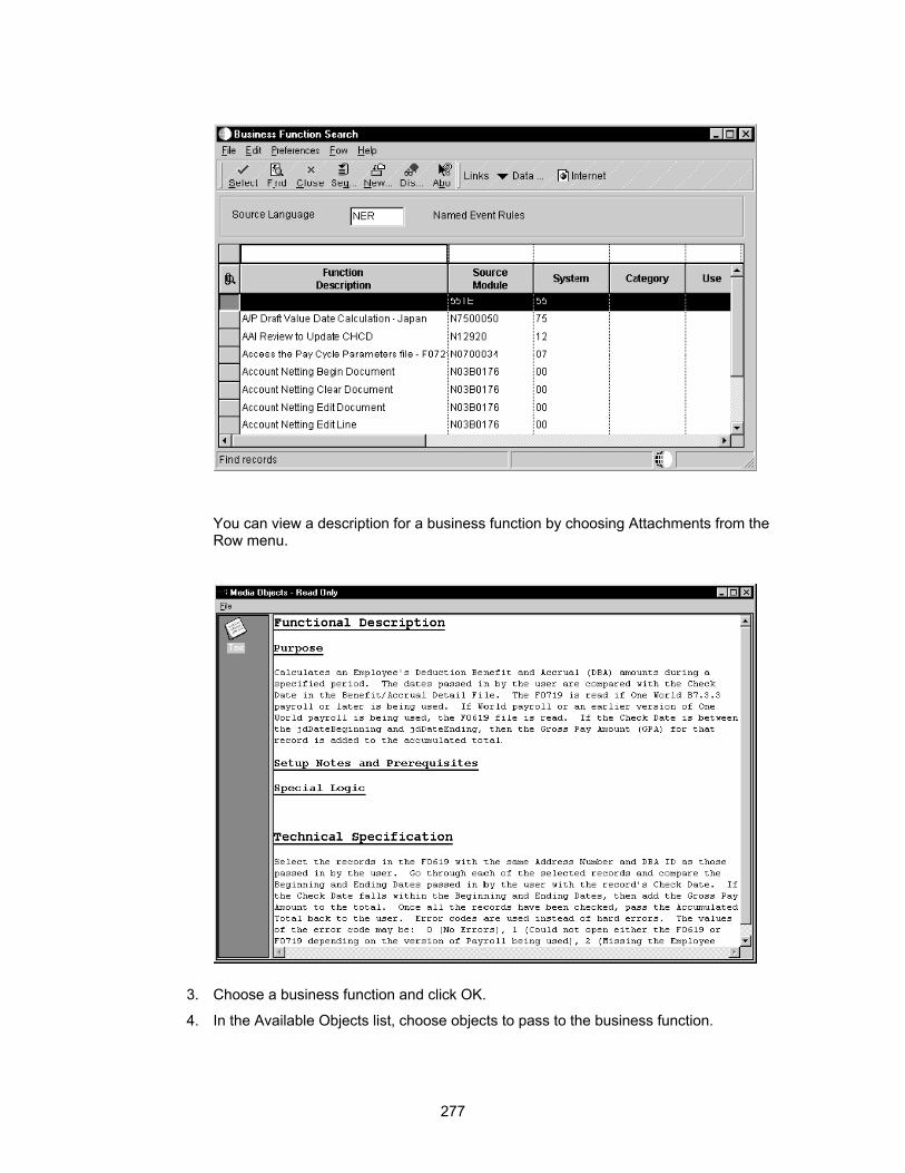
You can view a description for a business function by choosing Attachments from the Row menu.
3. Choose a business function and click OK.
4. In the Available Objects list, choose objects to pass to the business function.
277
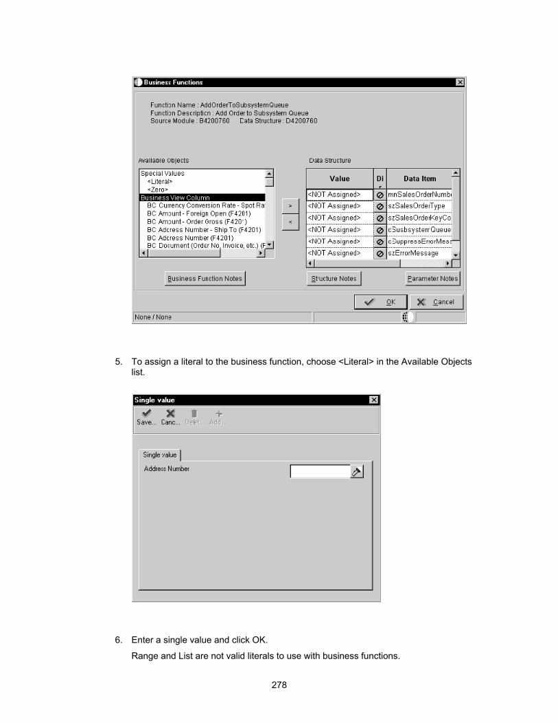
5. To assign a literal to the business function, choose <Literal> in the Available Objects list.
6. Enter a single value and click OK.
Range and List are not valid literals to use with business functions.
278

7. Indicate the direction of data flow between Value and Data Items, and click OK.
As you click the direction arrow, it toggles through the following four options:
! Data flows from the source to the target
z Data flows from the target to the source
$ Data flows from the source to the target, and upon exiting the target, data flows back to the source
No data flow
Data flows from the source to the target
Data flows from the target to the source
From the source to the target, and upon exiting the target, data flows back to the source
No data flow
If the direction of the items is hard-coded in the data structure for a business function (such as when the parameters are predetermined to be input, output, or bidirectional), then this predetermined direction appears here. If the direction of items is not critical, it can be omitted or set by the user. You must complete the required items that appear in red. The status bar indicates the state of the flow to the target.
8. Turn on the Include in Transaction option to include this business function for transaction processing.
This option appears only if you are calling from a Fix/Inspect, Header Detail, or Headerless Detail form. Refer to Transaction Processing for more information about transaction processing.
9. Turn on the Asynchronously option to enable asynchronous processing.
This option appears for the Post Button Clicked event, or for any Cancel or OK button on a Fix/Inspect form, Header Detail form, or Headerless Detail form. Refer to Working with Asynchronous Processing for more information.
10. You can click one of the following buttons to add notes.
• Business Function Notes
• Structure Notes
• Parameter Notes
11. Click OK.
J.D. Edwards Design Standards Always use the directional arrows to attach business functions. If you do not use a parameter, then use the symbol. This symbol also performs the following functions:
• Identifies when a parameter has been forgotten or needs to be added, such as when a business view changes or a work field is deleted
• Serves as documentation to other readers of the code
279
• Prevents memory from being reserved when it is not needed
Because they are acceptable internationally, use numeric values for any event rule flags that are passed back from the business functions. For example, to assign true/false values, use 1 for true and 0 for false, instead of T and F or Y and N.
Refer to Business Functions for more information about business functions.
Creating Form Interconnections
Use form interconnections to automatically pass data from one form, the source, to another form, the target.
Before You Begin Define the data structure of the receiving form to include any field for which you are
passing values.
Creating a Modal Form Interconnection
Most form interconnections are modal. This means that after a form interconnects to another form, the user must close the second form before interacting with the first form again.
► To create a modal form interconnection`
1. On Event Rules Design, choose an event.
2. Click the Interconnect button.
3. On Work with Applications, choose the application to which you are connecting.
Work with Forms displays forms for the selected application.
4. Choose the appropriate form to which you want to connect (the target).
5. Choose the appropriate version of the form to which you want to connect.
The Data Item column displays data items in the data structure of the target form. The keys in the primary unique index for the primary table of the business view are automatically set up as the data structure.
6. In the Available Objects column, select the object that you want to pass.
7. Use the > button to move it to the Data Structure-Value Column.
Indicate the direction of data flow between Value and Data Items.
If you do not want data to pass between forms, set all Direction values to null, and then click OK to save the Form Interconnection and exit.
As you click the direction arrow, it toggles through the following five options:
Data flows from the source to the target
Data flows from the target to the source
Data flows from the source to the target, and, upon exiting the target, data flows back to the source.
Upon exiting the target, data flows back to the source
280

No data flows either way
8. Turn on the Include in Transaction option to include this interconnection for transaction processing.
This option appears only if you are calling from a Fix/Inspect, Header Detail, or Headerless Detail form. Refer to Transaction Processing for more information.
9. Click one of the following buttons to add notes:
• Structure Notes
• Parameter Notes
10. After the data structure is defined, click OK.
Event Rules Design displays the Form Interconnection with the following statement:
Call (Application <name> Form <name>)
J.D. Edwards Design Standards The following standards apply to all form types:
• Accept the default placement of primary unique key fields at the top of the data structure.
• Change the data item name and description to describe the item that is passed between forms.
Creating a Modeless Form Interconnection
You can create a modeless form interconnection between a Find/Browse form and one or more Fix/Inspect forms or transaction forms (Header and Headerless Detail forms). Modeless processing allows the user to interact with two or more forms at the same time instead of having to close one form to return to the other. When you update the transaction form, you do not need to reinquire on the database before the update appears on the Find/Browse form. After the initial Find/Browse, you can access any form type, including another Find/Browse.
Each time the system calls a modeless form interconnection, it passes the values in the form data structure. When you click Cancel in the calling form, the system destroys the called form and does not pass any values. When you click OK in the called form, the system passes values back to the calling form through the form data structure. The called form still appears.
The Dialog is Initialized event occurs only the first time that the system calls it. If you want event rules to run each time a form appears, attach them to Post Dialog is Initialized.
If a form in update mode fails to fetch a record from the database, the form mode changes to Add mode. If the Close Form On Add option is turned on, the form closes when you click OK.
When you close a Find/Browse form, it closes all of the modeless interconnect records before it destroys itself.
Event rules that follow a modeless form interconnection execute immediately instead of waiting for the called form to return.
Run applications with modeless processing from the menu. If you run an application from Object Librarian, modeless processing does not work.
281

► To create a modeless form interconnection
1. On Event Rules Design for the Browse form that you want to use (the source), choose an event.
2. Click the Form Interconnection button.
282
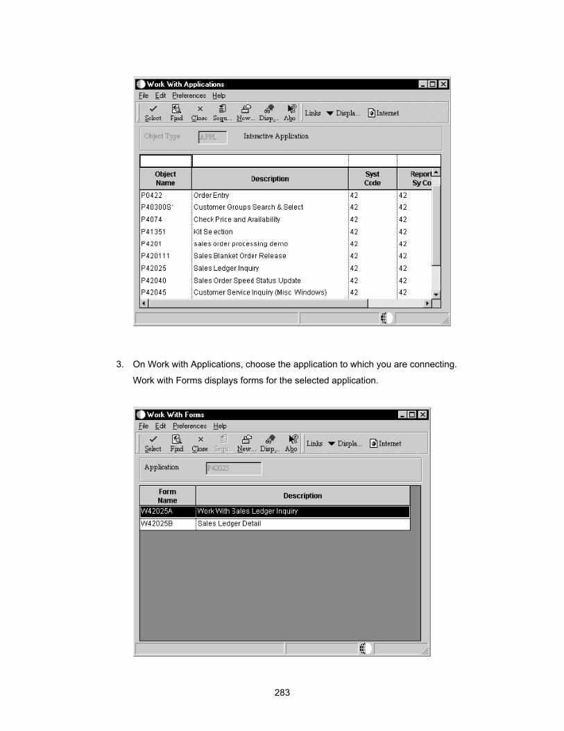
3. On Work with Applications, choose the application to which you are connecting.
Work with Forms displays forms for the selected application.
283

4. Choose the appropriate Fix/Inspect form to which you want to connect (the target). The Form Interconnect - Values to Pass window displays the data structure for the target form.
5. Choose the appropriate versions of the Fix/Inspect form to which you want to connect.
The Data Item column displays data items in the data structure of the target form. The keys in the primary unique index, for the primary table of the business view, are automatically set up as the data structure.
284
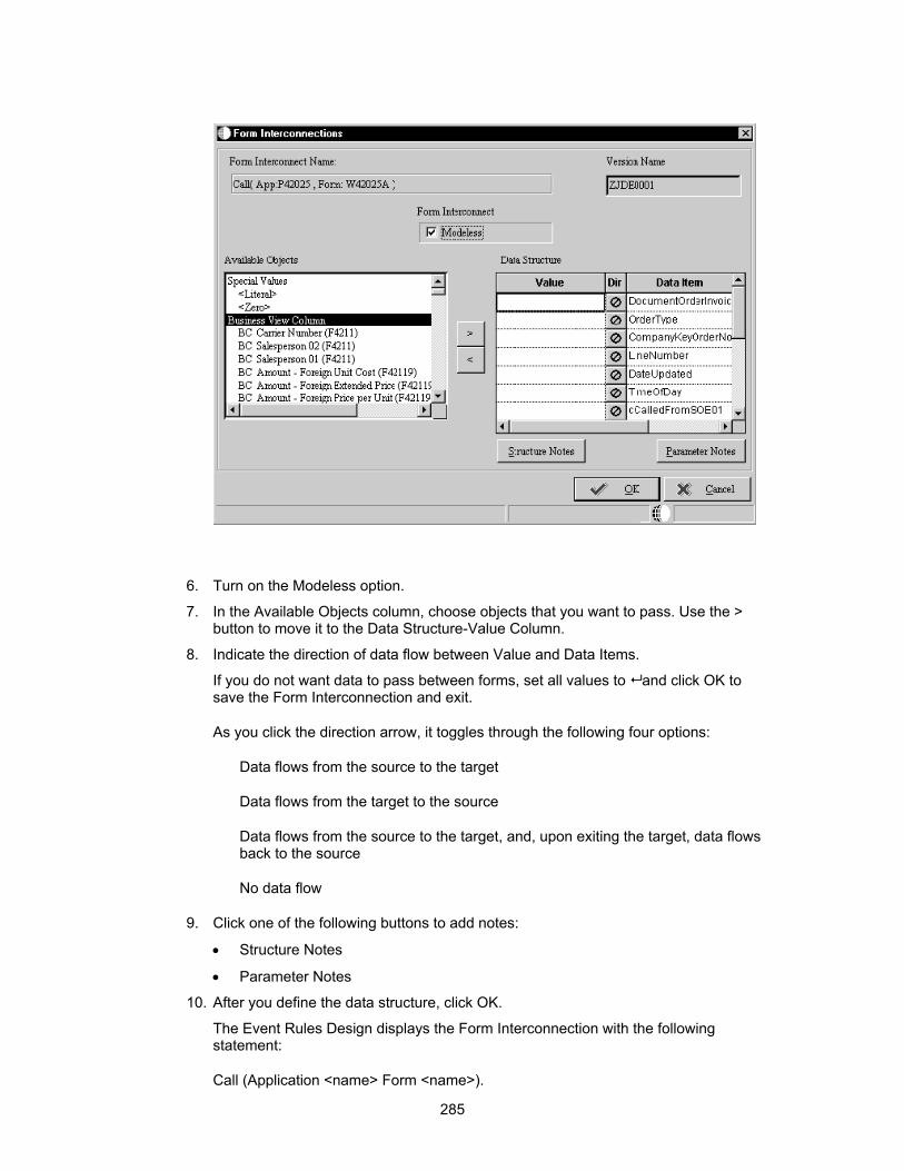
6. Turn on the Modeless option.
7. In the Available Objects column, choose objects that you want to pass. Use the > button to move it to the Data Structure-Value Column.
8. Indicate the direction of data flow between Value and Data Items.
If you do not want data to pass between forms, set all values to and click OK to save the Form Interconnection and exit.
As you click the direction arrow, it toggles through the following four options:
Data flows from the source to the target
Data flows from the target to the source
Data flows from the source to the target, and, upon exiting the target, data flows back to the source
No data flow
9. Click one of the following buttons to add notes:
• Structure Notes
• Parameter Notes
10. After you define the data structure, click OK.
The Event Rules Design displays the Form Interconnection with the following statement:
Call (Application <name> Form <name>).
285
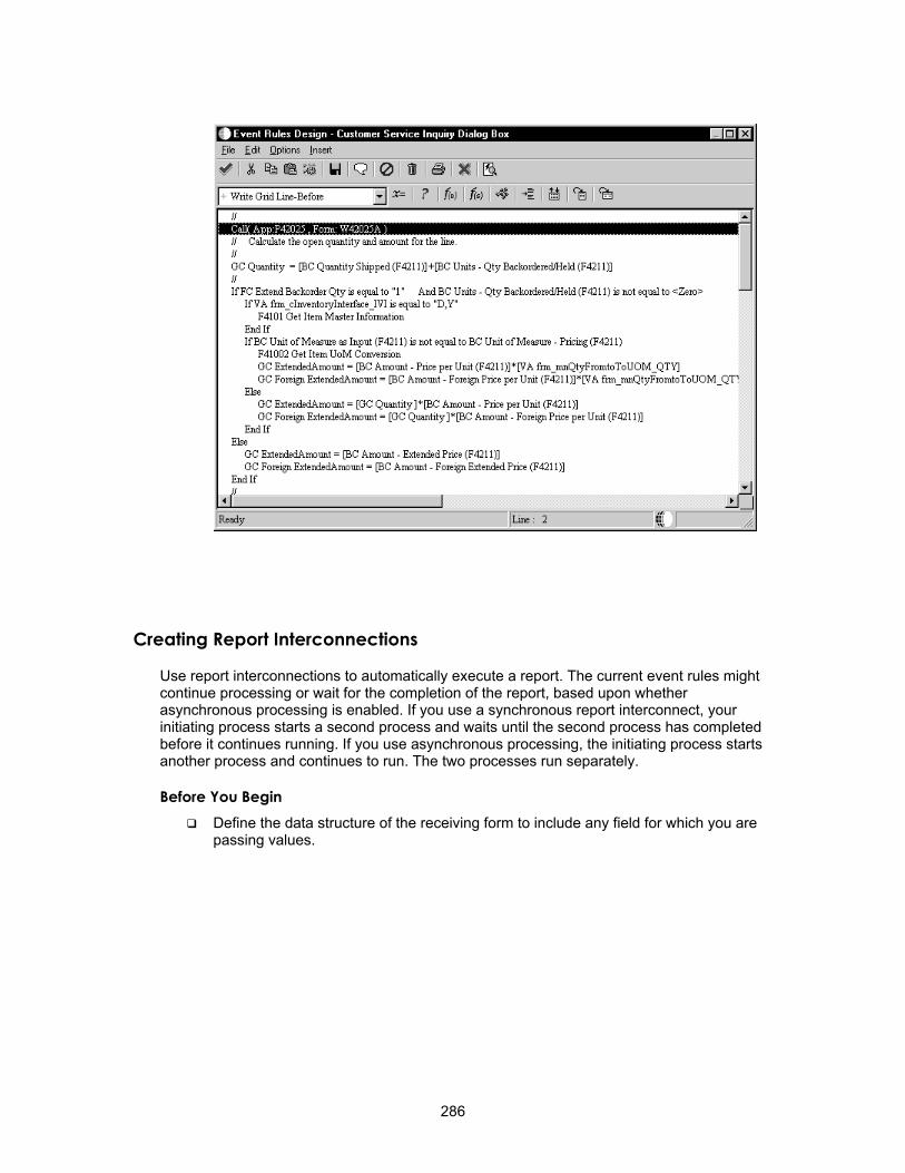
Creating Report Interconnections
Use report interconnections to automatically execute a report. The current event rules might continue processing or wait for the completion of the report, based upon whether asynchronous processing is enabled. If you use a synchronous report interconnect, your initiating process starts a second process and waits until the second process has completed before it continues running. If you use asynchronous processing, the initiating process starts another process and continues to run. The two processes run separately.
Before You Begin Define the data structure of the receiving form to include any field for which you are
passing values.
286

► To create a report interconnection
1. On Event Rules Design, choose an event.
2. Click the Report Interconnection button.
3. On Work with Applications, choose the report to which you are connecting.
287

Work with Versions displays versions for the selected report.
4. Choose the appropriate version of the report to which you want to connect.
288

5. In the Available Objects column, choose the object that you want to pass. Use the > button to move it to the Data Structure-Value Column.
Upon exiting the target, data flows back to the source
7. To run the report as a separate process, click the following option:
6. Indicate the direction of data flow between Value and Data Items.
If you do not want data to pass between reports, set all Direction values to and click OK to save the Report Interconnection and exit.
As you click the direction arrow, it toggles through the following four options:
Data flows from the source to the target
Data flows from the target to the source
No data flow
• Asynchronously
You must turn on this option if you want to pass data into the report.
8. To include the report interconnect for transaction processing, click the following option:
• Include in Transaction
9. Click one of the following buttons to add notes:
• Structure Notes
• Parameter Notes
10. After the data structure is defined, click OK.
Event Rules Design displays the Report Interconnection with the following statement:
Call (UBE <name> Version <name>)
289
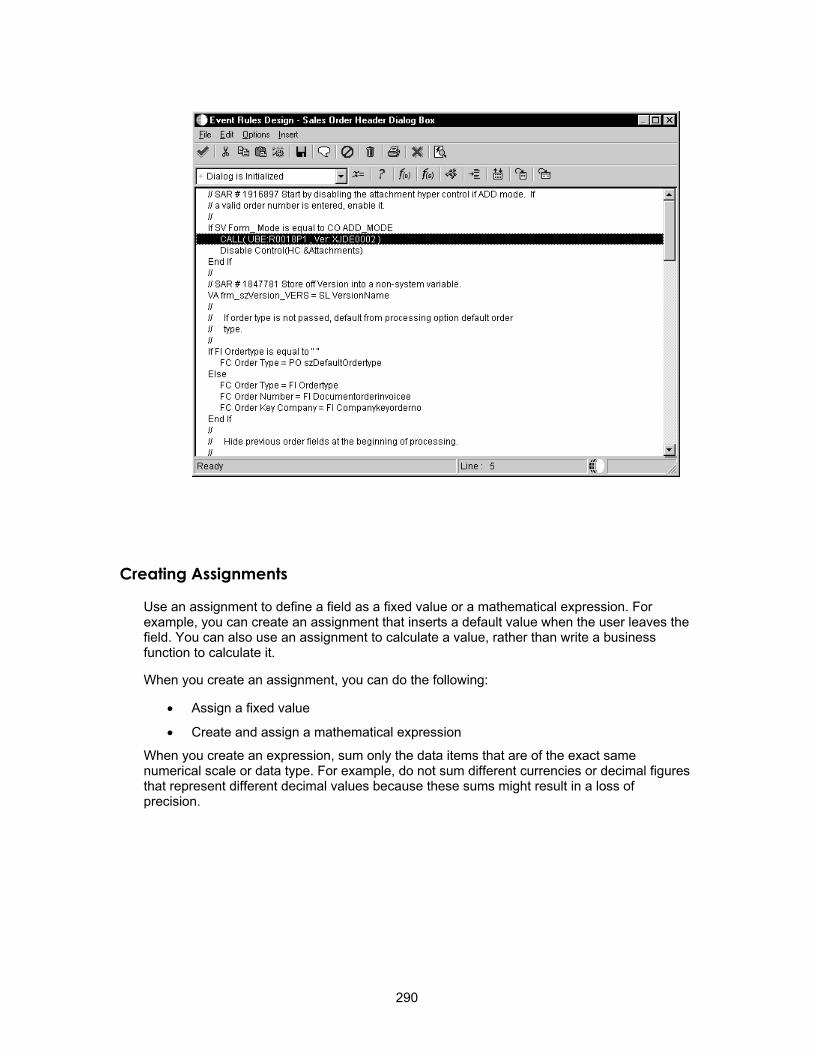
Creating Assignments
Use an assignment to define a field as a fixed value or a mathematical expression. For example, you can create an assignment that inserts a default value when the user leaves the field. You can also use an assignment to calculate a value, rather than write a business function to calculate it.
When you create an assignment, you can do the following:
• Assign a fixed value
• Create and assign a mathematical expression
When you create an expression, sum only the data items that are of the exact same numerical scale or data type. For example, do not sum different currencies or decimal figures that represent different decimal values because these sums might result in a loss of precision.
290

The available objects that appear are based on the data type.
► To assign a value
1. On Event Rules Design, choose an event.
2. Click the Assign button.
3. Choose an object on the left that you want to receive your assigned value.
4. Determine the From value using one of the following methods:
291

• Choose a From Object in the right-hand column to create a simple statement: [left-hand column] = [right-hand column].
• Type a literal expression (number, text, and so on) in the text entry box to assign a literal statement: [left-hand column] = [literal].
• Press the f(X) button to create a complex expression or advanced mathematical function using the Expression Manager.
5. Click OK.
The Event Rules Design window displays the assignment in text form.
292

► To create an expression for an assignment
1. From the Assignment form, click the f(X) button.
2. Create the expression in the edit field.
Either type the expression or use the object list, calculator pad, and functions list. Use the following buttons as you edit your expression:
Clear Clears all data from the Assignment Display
Bksp Deletes the previous expression or character
Undo Reverses your previous editing action (other than inserting objects or functions from the lists)
3. Click OK when you are finished editing your expression.
The Assignment Display checks and highlights any spelling or syntax errors. If it detects no errors, the expression returns to Event Rules Design.
293

Expression Manager
Expression Manager has several different sections with which you can work.
Assignment Display The first section of the Expression Manager form displays the current status of the assignment expression. To Object displays the object to which the expression will be assigned. From Expression displays either a blank entry or the expression being edited.
• Advanced functions
Expression Editing Field Create and edit the expression in the editing field.
You can enter text by typing characters from the keyboard, using the editing keypad, or double-clicking the mouse to point and click to various expression components, including the following:
• Objects
• Numbers and mathematical symbols
The editing field accepts any expression, in any order. If syntax errors occur, the system highlights the error and displays it in the status bar.
294

Available Information The Available Information list contains all of the objects that are available for creating and editing expressions. You can choose an object in the list box to display its data type in the status bar.
Editing Keypad You can use the editing keypad to enter data into an expression instead of using the keyboard. The Undo button is enabled only when it can undo the last editing operation that you performed. It cannot undo inserts from either the Available Information list or the Advanced Functions list.
Advanced Functions The Advanced Functions list contains functions that are available to create or edit an expression. You can display information about functions in the status bar. The first box displays a short description of the function, and the second box displays the syntax for the function. Advanced Functions include:
• Date functions
• General functions
• Trig functions
• Text functions
Date Functions
Function Description add_days(date, days) Adds a specified number of days to the date
add_months(date, months) Adds a specified number of months to the date
days_between(date1, date2) Returns the number of days between date1 and date2
months_between(date1, date2)
Returns the number of months between date1 and date2
date_day(date) Returns the day for the specified date
date_month(date) Returns the month of the year for the specified date (1=January, 2=February,...)
date_today( ) Returns today's date
date_year(date) Returns the year for the specified date (in 19xx format)
last_day(date) Returns the last day of the month of the specified date (not day of the week)
next_day(date, day_of_week) Returns the next date that occurs on the day of the week after a given date
295
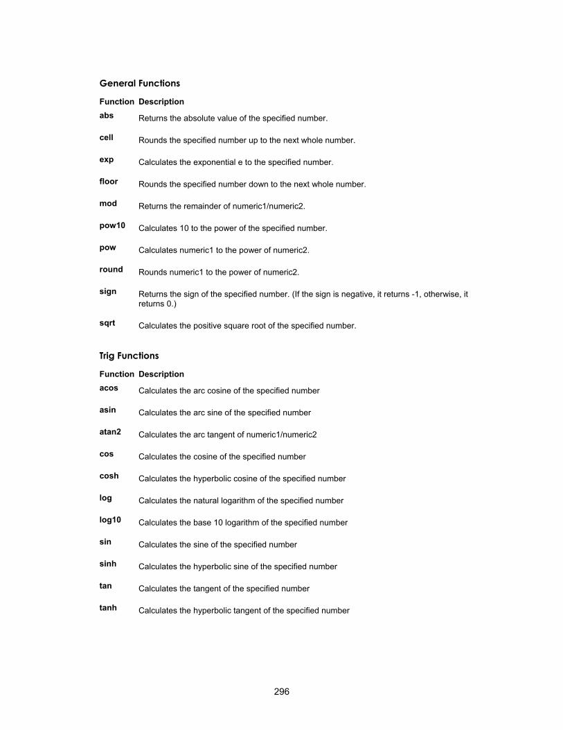
General Functions
Function Description abs Returns the absolute value of the specified number.
cell Rounds the specified number up to the next whole number.
exp Calculates the exponential e to the specified number.
floor Rounds the specified number down to the next whole number.
mod Returns the remainder of numeric1/numeric2.
Returns the sign of the specified number. (If the sign is negative, it returns -1, otherwise, it returns 0.)
pow10 Calculates 10 to the power of the specified number.
pow Calculates numeric1 to the power of numeric2.
round Rounds numeric1 to the power of numeric2.
sign
sqrt Calculates the positive square root of the specified number.
Trig Functions
Function Description acos Calculates the arc cosine of the specified number
asin Calculates the arc sine of the specified number
atan2 Calculates the arc tangent of numeric1/numeric2
cos Calculates the cosine of the specified number
cosh Calculates the hyperbolic cosine of the specified number
log Calculates the natural logarithm of the specified number
log10 Calculates the base 10 logarithm of the specified number
sin Calculates the sine of the specified number
sinh Calculates the hyperbolic sine of the specified number
tan Calculates the tangent of the specified number
tanh Calculates the hyperbolic tangent of the specified number
296

Text Functions
Function Description concat Appends string2 to string1
indent Indents string a given length of characters indent("abcde",'5',5)="+++++abcde"
length Returns the length of a string length("axcvbnm") = 7
lower Converts specified string to lowercase lower("AbCdEfG") = "abcdefg"
lpad Inserts the character into the front (left side) of the string until the string is length long lpad("qwerty",' ',12) = "...... qwerty"
ltrim Removes leading occurrences of the character from the string ltrim("aaaaaabcdef" , 'a') = "bcdef"
rpad Inserts the character into the back (right side) of the string until the string is length long rpad("qwerty" , '.', 10) = "qwerty...."
rtrim Removes trailing occurrences of the character from the string rtrim("abcdef ",' ') = "abcdef"
substring Extracts a portion of string beginning at position for length number of characters substring("SUNMONTUEWEDTHUFRIS AT", 9,3) = "WED"
Note: The beginning position of the string is considered position zero; to substring beginning with the 10th character, use 9 as the beginning position in the command.
upper Converts specified string to uppercase upper("qweRTY") = "QWERTY"
Table I/O
Use the Table I/O button in Event Rules Design to create instructions that perform table input and output (I/O) so that you do not need to manually code a business function in C code. Table I/O allows you to access a table through event rules. For example, you can use table I/O to display information in a table that your application does not use. You can use table I/O to do the following:
• Validate data
• Retrieve records
• Update or delete records across files
• Add records
You can use Log Viewer to view your table I/O SQL statements in the jdedebug.log. (Your jde.ini file must have debugging set to File.)
297
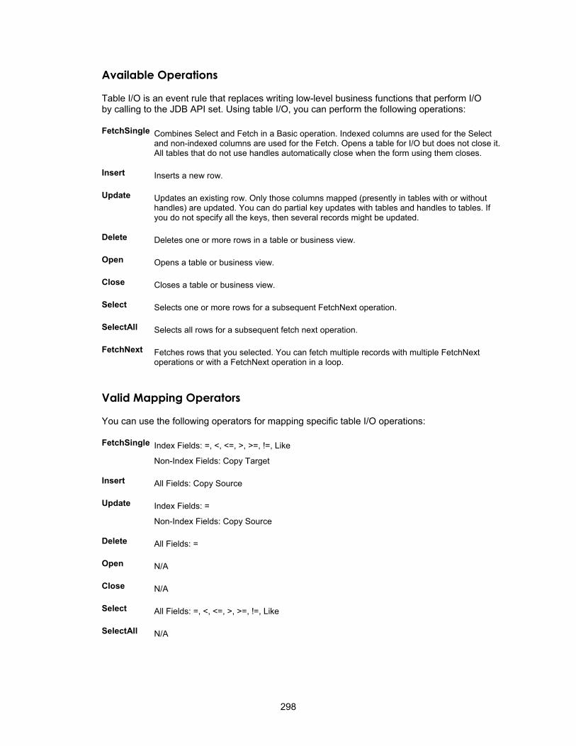
Available Operations
Table I/O is an event rule that replaces writing low-level business functions that perform I/O by calling to the JDB API set. Using table I/O, you can perform the following operations:
FetchSingle Combines Select and Fetch in a Basic operation. Indexed columns are used for the Select and non-indexed columns are used for the Fetch. Opens a table for I/O but does not close it. All tables that do not use handles automatically close when the form using them closes.
Insert Inserts a new row.
Update Updates an existing row. Only those columns mapped (presently in tables with or without handles) are updated. You can do partial key updates with tables and handles to tables. If you do not specify all the keys, then several records might be updated.
Delete Deletes one or more rows in a table or business view.
Open Opens a table or business view.
Close Closes a table or business view.
Select Selects one or more rows for a subsequent FetchNext operation.
SelectAll Selects all rows for a subsequent fetch next operation.
FetchNext Fetches rows that you selected. You can fetch multiple records with multiple FetchNext operations or with a FetchNext operation in a loop.
Valid Mapping Operators
You can use the following operators for mapping specific table I/O operations:
FetchSingle Index Fields: =, <, <=, >, >=, !=, Like
Non-Index Fields: Copy Target
Insert All Fields: Copy Source
Update Index Fields: =
Non-Index Fields: Copy Source
Delete All Fields: =
Open N/A
Close N/A
Select All Fields: =, <, <=, >, >=, !=, Like
SelectAll N/A
298

Creating a Table I/O Event Rule
Table I/O event rules allow event rule support for database access. You need event rule support to perform table input and output, data validations, and record retrieval.
► To create a table I/O event rule
1. On Event Rules Design, click the Table I/O button.
2. Choose the operation you wish to use, and then click Next.
299
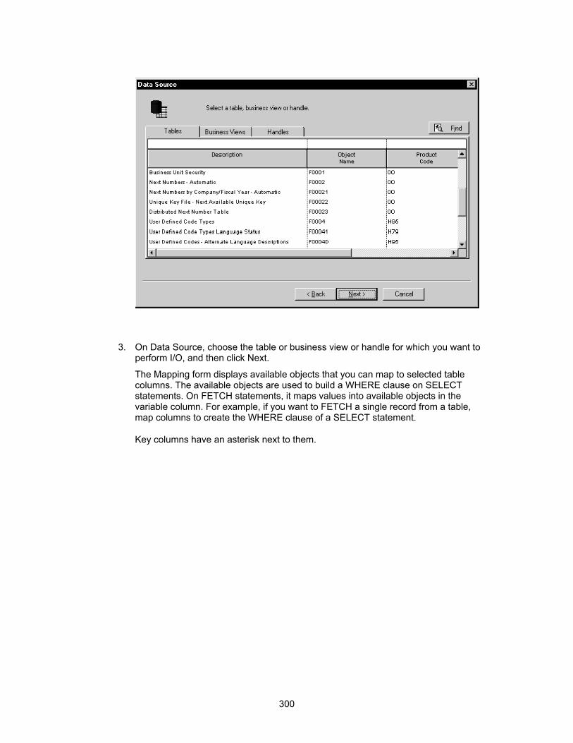
3. On Data Source, choose the table or business view or handle for which you want to perform I/O, and then click Next.
The Mapping form displays available objects that you can map to selected table columns. The available objects are used to build a WHERE clause on SELECT statements. On FETCH statements, it maps values into available objects in the variable column. For example, if you want to FETCH a single record from a table, map columns to create the WHERE clause of a SELECT statement.
Key columns have an asterisk next to them.
300

4. Choose the column that you want to use and then double-click on the available objects that you want to map to that column.
5. Click the Operator button until you have the operation that you want.
The following selection operations are available. The default is equal.
• Equal
• Not Equal
• Less Than
• Less Than or Equal To
• Greater Than
• Greater Than or Equal
• Like
6. Click Finish to save the operation and return to Event Rules Design.
Record Change If you choose the Update option, you can also enable Check for Record Change. The Check for Record Change option indicates whether the record has been changed between the time that it was fetched and the time that it is updated.
301
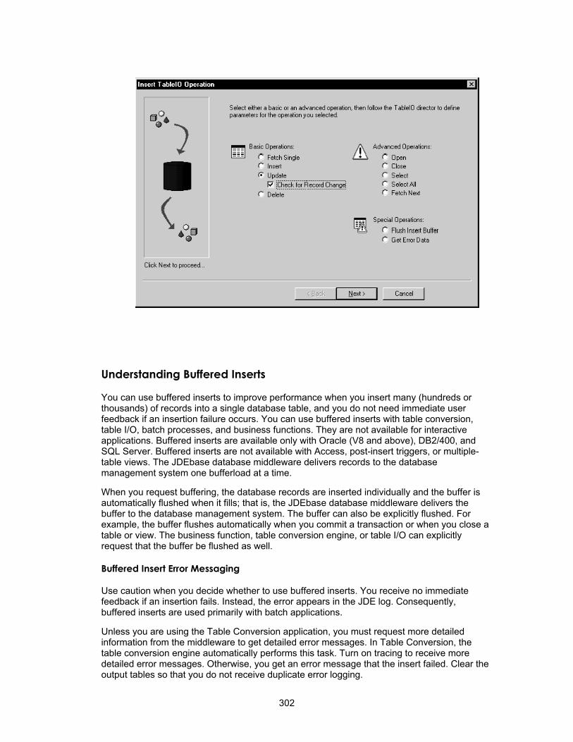
Understanding Buffered Inserts
You can use buffered inserts to improve performance when you insert many (hundreds or thousands) of records into a single database table, and you do not need immediate user feedback if an insertion failure occurs. You can use buffered inserts with table conversion, table I/O, batch processes, and business functions. They are not available for interactive applications. Buffered inserts are available only with Oracle (V8 and above), DB2/400, and SQL Server. Buffered inserts are not available with Access, post-insert triggers, or multiple-table views. The JDEbase database middleware delivers records to the database management system one bufferload at a time.
When you request buffering, the database records are inserted individually and the buffer is automatically flushed when it fills; that is, the JDEbase database middleware delivers the buffer to the database management system. The buffer can also be explicitly flushed. For example, the buffer flushes automatically when you commit a transaction or when you close a table or view. The business function, table conversion engine, or table I/O can explicitly request that the buffer be flushed as well.
Buffered Insert Error Messaging
Use caution when you decide whether to use buffered inserts. You receive no immediate feedback if an insertion fails. Instead, the error appears in the JDE log. Consequently, buffered inserts are used primarily with batch applications.
Unless you are using the Table Conversion application, you must request more detailed information from the middleware to get detailed error messages. In Table Conversion, the table conversion engine automatically performs this task. Turn on tracing to receive more detailed error messages. Otherwise, you get an error message that the insert failed. Clear the output tables so that you do not receive duplicate error logging.
302

Using Buffered Inserts in Table I/O
When you use buffered inserts in table I/O, you must explicitly open the table with an Open.
Choose the table that you want to use and click Advanced Options.
Special Operations After you set up buffered inserts, you can use Special Operations to flush the buffers or get error messages. In Event Rules, at the point at which you want to perform one of these operations, click either of the following options:
• Flush Insert Buffer
To maintain data integrity, you should flush the insert buffer before you perform any operations other than an insert. If you fail to do so, the results of recent inserts might not be reflected in other operations, and the operations might not work properly.
303

When you use the flush insert buffer option for a specific table, you must flush the buffer before you close the table so that you still have access to error information. You can use the Get Error Data option for each insert to ensure that you get this information.
• Get Error Data
The Get Error Data option retrieves errors for records that did not insert properly. Depending on when your buffers are flushed, or when you begin another insert, you might overwrite the error information for a specific insert. If error information is critical, retrieve the information before the next insert begins.
If you need to perform special error handling, you should set it up after each table I/O insert and each Flush Insert Buffer option. Always retrieve the error information before you begin your next table operation.
Understanding Handles
In OneWorld, the table I/O term handle refers to a type of file pointer. This file pointer connects the OneWorld application or UBE with the middleware that communicates with the database manager. Handles point to a database table, and they are references to an address within the middleware. Unlike regular file pointers, handles allow you some control over when and how they are used. Handles allow you to perform the following operations, which you cannot perform using nonhandle table I/O operations:
• You can use handles to concurrently open multiple instances of a single table or business view.
• You can use handles to open a table or business view in an environment other than the environment that you signed on to. This feature is particularly helpful when you receive an upgrade to OneWorld or when you need to convert data from another system into OneWorld.
• You can pass handles into a form, named event rule, or business function so that you do not need to open a table or business view more than once.
You cannot use handles in transaction processing.
If you pass a handle to a form or a named event rule, the data structure for the form or named event rule must contain a member that is a handle data item. In the form interconnect or business function call, you must assign a handle value from your event rules to the handle data structure member. You can use this handle in the form or named event rule that is receiving the handle in the same way that you use any other handle.
You must explicitly open and close handles, unlike other table I/O operations in which you can use implicit open and close statements. You must open a handle before you can use it for any other operations. All of the operations except Open work the same for handles as they do for tables or business views. When you are finished using a handle, you must explicitly close it. You close the handle in the same way in which you close a table or business view, except that you choose a handle instead of a table or business view.
Using a Handle
To use a handle, you must complete the following:
• Define the handle in the data dictionary
• Create a handle variable in event rules
304

• Open the handle explicitly
After you create a handle data item, you must create a handle variable. You create a handle variables in the same way in which you create other variables. You can use any scope necessary to create the handle variable. See Working with Event Rule Variables for more information about creating variables.
After you create a handle variable, you must explicitly open the handle. Then, after performing the required table I/O, you must explicitly close it.
► To use a handle
Use a Class Type of Handle and a Data Type of 7. You should name the alias for the handle the same as its table.
1. To complete the handle data item, click the Edit Rule tab, type the table or business view name for the handle, and then save the data dictionary item.
The data item name can be a maximum of eight characters and should be formatted as follows: HFxxxxxx
HF = Designates a table I/O data item
xxxxxx = Represents the system code and group type used in the table name
For example, the table I/O data item name for table F4211 is HF4211.
305

See Data Dictionary for more information about data items. You can also create a handle data item in a data structure.
2. On Event Rules Design, click the Table I/O button.
3. From Advanced Operations, click Open.
306

4. Click Next.
5. On Data Source, click the Handles tab.
6. Choose the handle that you want to open, and then click Next.
7. Choose a variable that contains the name of the environment in which you want to open the table.
If you want to open the table in the login environment, choose the system value SL LoginEnvironment. System values also exist for the source and target environment in Table Conversion if you use Table I/O in Table Conversion.
8. Click Finish.
9. On Data Source, click the Handles tab.
10. Choose the handle that you want to close, and then click Finish.
Table Event Rules
You use table event rules (TER) to attach database triggers (or programs) that automatically run whenever an action occurs against the table. An action against a table is called an event. When you create a OneWorld database trigger, you must first determine which event activates the OneWorld database trigger. Then, use Event Rules Design to create the database trigger.
Table event rules provide embedded logic at the table level. Table event rules have their own location, events, and system functions. When you use table event rules, neither the calling application nor the user is notified of changes or events to the table. No form or report interconnection is available with table event rules.
You can use table event rules for data integrity. For example, when you delete a record in address book, you might want to delete all associated records, such as phone and category codes. You can also use table event rules for currency. The Currency Conversion is On event rule handles currency information in table event rules. Refer to Currency for more information.
Following are the events to which you can attach event rules on a table-by-table basis:
• After Record is Deleted
• After Record is Fetched
• After Record is Inserted
• After Record is Updated
• Before Record is Deleted
• Before Record is Fetched
• Before Record is Inserted
• Before Record is Updated
• Currency Conversion is On
Refer to the online help Published APIs for information, such as typical use and processing sequence, about these events.
307

Creating Table Event Rules
To create a table event rule, you must perform the following:
• Create the database trigger in Event Rules Design
• Generate the OneWorld database trigger as C code
► To create table event rules
1. On Object Management Workbench, check out the table you want to attach event rules to.
2. On Table Design, click the Design Tools tab, and then click Start Table Trigger Design Aid.
This starts Event Rules Design, which you can use to attach event rules to any of the events for the table.
3. From the Events list, choose an event.
4. Click one of the following event rule buttons:
Business Function
Attaches an existing business function.
System Function
Attaches an existing J.D. Edwards system function.
If/While Creates an IF/WHILE conditional statement.
Assign Creates an assignment or a complex expression.
308

Else Inserts an ELSE clause, which is only valid within the bounds of IF and ENDIF.
Variables Creates a programmer-defined field, which has data dictionary characteristics for application-specific purposes, but does not reside in the data dictionary.
Table I/O
You do not need to create and associate data structures to the table event rule (TER) functions. The table itself is the data structure that is passed to the table event rule function.
Allows event rule support for database access. Performs table input and output, data validations, and record retrieval.
5. On Event Rules Design, click Save to save your event rule specifications, then click Close to return to Table Design.
6. If you are creating a new table, in Table Design, click the Table Operations tab, and then click Generate Table.
Caution Never perform this step on an existing table. This clears all data. Only perform step this for New Tables.
7. On Generate Table, complete the following fields, and then click OK:
• Data Source
• Password
8. On Table Design, click the Design Tools tab, and then click Build Table Triggers.
The Build Triggers option performs the following steps:
309

• Converts the ER to C source code. This creates the files OBNM.c and OBNM.hxx (OBNM = Object Name). The source file will contain one function per table event rule event.
• Creates a make file to compile the generated code.
• Runs the make file to compile the new functions and to add them into JDBTRIG.DLL. This Consolidated DLL contains table event rule functions.
9. To see a log of the build, click Generate Header File, and then open the file that is created by the system.
The creation of the table event rule is complete. The newly created or modified table event rule functions can now be called from the database APIs whenever the corresponding event occurs against the table.
Creating Dynamic Overrides
Some applications have generic form controls or grid columns in which the control properties (such as row or grid description, visual assist, and edit rules) are unknown until the user enters specific information or until specific data is loaded. In these cases, the system must dynamically override control properties at runtime. For example, an application might need to display the ending date for a field instead of static text, or you might want to change the visual assist search form when a user clicks on the visual assist button.
You can use system functions to override data dictionary properties at runtime. You can use the Set Data Dictionary Item system function to do the following:
• Override form controls and grid columns that are data dictionary items
• Change the data dictionary item completely so that all data dictionary properties are changed
310

• Create a new data item that is not the same type as the old item
You can use a data item name that is a string variable or a hard-coded string.
You can use the Set Data Dictionary Overrides system function for the following:
• All form controls and grid columns
• Changes to a specific data dictionary property
• Data dictionary item that are not changed
You can use the following system functions to override text at runtime:
• Set Control Text
• Set Grid Column Heading
• Set Form Title
These system functions are commonly used with text variables. You can also use the grid column system functions for Parent/Child forms. The grid column overrides work for all grid rows, and existing functionality remains intact.
You can use the following events to override a visual assist:
• Visual Assist Button Clicked
• Post Visual Assist Button Clicked
You can use also use the Suppress Default Visual Assist system function to override a visual assist and affect the next visual assist form. After you suppress the default visual assist form, you can use form interconnections to call another form instead of the Search and Select form.
Working with Asynchronous Processing
A thread is a path of execution that is separate from the main path of execution. The act of creating a thread is similar to calling a function, except that the main program also continues running. This means that two points of execution progress through the code. The different threads share the same memory space, and the operating system assigns processor time to them.
Threads allow you to process selected OneWorld events or business functions in the background while the user continues to interact with the application.
Thread processing provides several performance benefits, including the following:
• Improves processing for grid and edit controls
• Processes certain events in the background so that the user does not have to wait for the system to finish
• Provides greater flexibility for event processing
• Allows multiple-task processing
• Allows the user to continue with interactive tasks, such as data entry
• Allows faster cursor movement
Though threads can significantly improve performance by using idle time to accomplish background processing, they also introduce a number of possible problems that are not present in single-threaded applications.
311

Events processed in the main path of execution and events processed in a thread can execute at the same time. Unpredictable results can occur when two events try to access the same data at the same time.
Asynchronous processing does not support form interconnections. You use asynchronous processes for background processing, and users should not interact with an asynchronous thread directly. For example, if you have an asynchronous process (such as Row is Exited and Changed - Asynch), you should not open a form on that worker thread because that requires the user to interact with a process that should be processing in the background.
Asynchronous Events
The following diagram illustrates how threaded events work.
Only one asynchronous event is processed at a time. Multiple instances of a unique asynchronous event might be waiting to process. The main thread continues, regardless of the presence or absence of asynchronous events in the queue. In the diagram, Asynchronous event exists determines whether the secondary thread starts; it does not alter the main thread.
All asynchronous events must complete their processing before OK or Cancel can be processed.
The following events can execute on a thread:
312

• Control is Exited and Changed - Asynch
• Row is Exited and Changed - Asynch
• Column is Exited and Changed - Asynch
Control is Exited and Changed - Asynch
As a control is exited, these three events process in the following sequence:
• Control is Exited
• Control is Exited and Changed - Inline
• Control is Exited and Changed - Asynch
The first two events are processed before the user can continue. The Control is Exited and Changed - Asynch event runs on a thread. That means that the user can continue entering data while the event executes.
Row is Exited and Changed - Asynch
As a grid row is exited, these three events process in the following sequence:
• Row is Exited
• Row is Exited and Changed - Inline
• Row is Exited and Changed - Asynch
The Row is Exited event is available on all grids. The other two events are available only on update grids (Header and Headerless Detail forms).
The first two events are processed before the user can continue. The Row is Exited and Changed - Asynch event runs on a thread. That means that the user can continue entering data while the event executes. As this event processes for a specific row, an hourglass appears in the row header.
Column is Exited and Changed - Asynch
As a grid column is exited, these three events process in the following sequence:
• Column is Exited
• Column is Exited and Changed - Inline
• Column is Exited and Changed - Asynch
These events are valid for update grids only (Header and Headerless Detail forms).
The first two events are processed before the user can continue. The Column is Exited and Changed - Async events runs on a thread. That means the user can continue entering data while the event processes.
Asynchronous Business Functions
Business functions that run on OK and Cancel processing often negatively affect performance. When possible, run these business functions on a thread. Event Rules Design has an asynchronous option on the form in which business function parameters are selected. The asynchronous option is disabled for all events except OK Post Button Clicked, Cancel Post Button Clicked, and Close Post Button Clicked. When the option is turned on, the business function processes on a thread. When the option is turned on, parameters can be
313

passed in, or not passed at all. You cannot pass parameters out of the business function because the form has continued and might not still be open.
Attempts to set errors during asynchronous business functions are ignored. The asynchronous business function has no connection to the form, so errors cannot be set. The runtime engine can, however, use the return code from jdeCallObject to determine if an asynchronous business function fails. A message box appears if a failure occurs. The message box allows you to quit processing when a failure occurs. You can review the logs for more information about the failure.
Asynchronous business functions are useful for forms that make many database calls as the form is closing. For example, a good candidate for threaded business functions is a form that uses jdeCache calls or workfiles to store records temporarily and then writes the temporary records to the actual files when OK is clicked.
The following diagram illustrates how threaded business functions work.
Only one asynchronous business function processes at a time. The main thread continues regardless of the presence or absence of asynchronous events in the queue. In the diagram, Asynchronous business function thread exists determines whether the secondary thread starts, it does not affect the main thread.
Asynchronous business functions must complete their processing before OneWorld Explorer can be closed. If asynchronous business functions are still running, a message appears, and OneWorld Explorer will not close.
314

Example: Asynchronous Event Processing
The following is an example of that functions that are attached to the Row is exited and Changed - Asynch event.
The Row is exited and Changed - Asynch event behind the grid in the Sales Order Detail form (P4210) has logic attached to it as follows.
For the first five highlighted lines, the system enters default information in certain table columns for the database update. For the last highlighted line, the F4211Begin Document (Master Business Function) is called.
BrowsER
You can use BrowsER to view event rules and design layout for interactive and batch applications. You can enable or disable one or more event rules without extensive work in the design tools. You use this feature to debug specific event rules.
BrowsER displays the structure of forms within an interactive application, or sections within a batch application. The forms or sections appear in a hierarchical structure, with events and event rules for each section.
Working with BrowsER
You can use BrowsER to disable or enable event rules, and then observe the effect on your application.
315
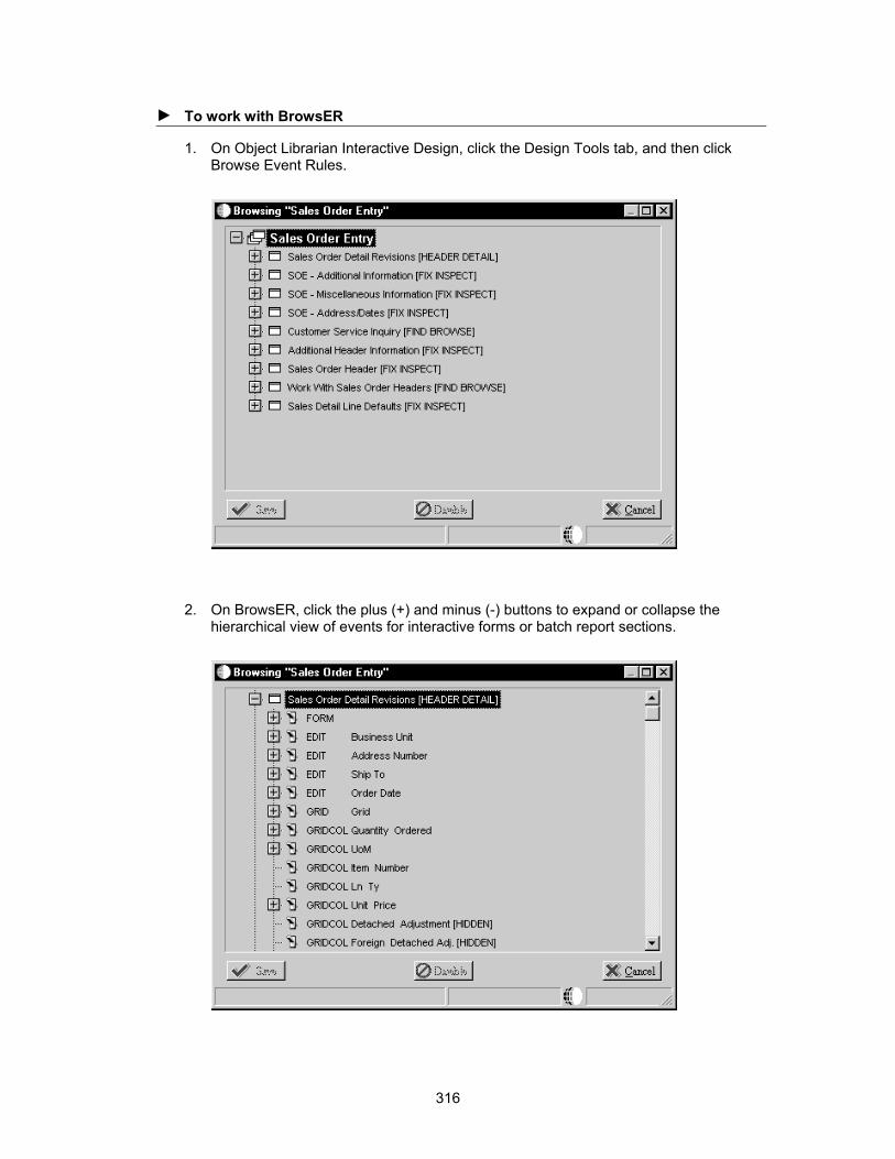
► To work with BrowsER
1. On Object Librarian Interactive Design, click the Design Tools tab, and then click Browse Event Rules.
2. On BrowsER, click the plus (+) and minus (-) buttons to expand or collapse the hierarchical view of events for interactive forms or batch report sections.
316

Each event rule appears beneath the event with which it is associated and also beside a control that contains event rule logic. If it does not appear beside a control, then no event rule logic exists on that control.
3. To disable an event rule for debugging, double-click on the event rule.
317
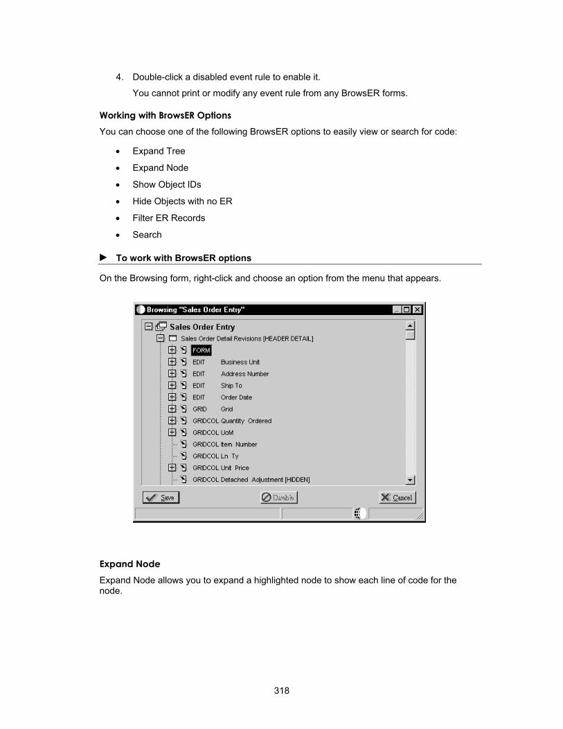
4. Double-click a disabled event rule to enable it.
• Filter ER Records
You cannot print or modify any event rule from any BrowsER forms.
Working with BrowsER Options You can choose one of the following BrowsER options to easily view or search for code:
• Expand Tree
• Expand Node
• Show Object IDs
• Hide Objects with no ER
• Search
► To work with BrowsER options
On the Browsing form, right-click and choose an option from the menu that appears.
Expand Node Expand Node allows you to expand a highlighted node to show each line of code for the node.
318
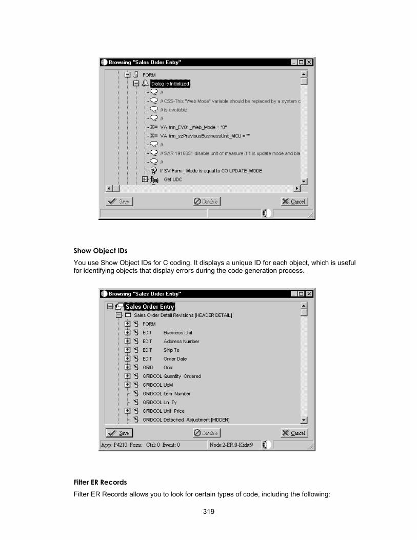
Show Object IDs You use Show Object IDs for C coding. It displays a unique ID for each object, which is useful for identifying objects that display errors during the code generation process.
Filter ER Records Filter ER Records allows you to look for certain types of code, including the following:
319

• Assignments
• Business Functions
• Criterion
• Comments
• Form Interconnects
• Options
• System Functions
Search Search allows you to search for a particular line of code. You can use it to find occurrences of particular strings or variables.
Using Visual ER Compare
Visual ER Compare is a utility that lets you compare ER on your local workstation to ER in the central objects data source of any defined pathcode, TAM specifications, or ESU backup. For example, if you change the ER for an application and then want to compare your changes to the ER in the server application, you can use Visual ER Compare.
Visual ER Compare provides a line-by-line, on-screen comparison. You can change the target ER (your local version) within the utility by moving lines directly from the source ER. You can also remove or disable lines. In addition to providing an on-screen comparison, you can also choose to print a report that lists the changes.
Launching Visual ER Compare
Apply the following task only to objects with attachable ER (applications, UBEs, tables, and business functions).
► To launch Visual ER Compare
From Cross Application Development Tools (GH902), choose Object Management Workbench.
1. On Object Management Workbench, check out an object.
2. Select the object that you checked out, and then click the Design button in the center column.
3. On the Design form, click the Design Tools tab.
4. Click Visual ER Merge.
5. On Select the Location of Source Specifications, perform one of the following actions:
• Click Select PathCode, and then enter the server location of the source object (the object to which you want to compare your local ER).
• Click Advanced TAM, and then enter the TAM location of the source object (the object to which you want to compare your local ER). ESUs are delivered in a TAM package, so use this method to compare your local ER to an object that is included in an ESU.
320

Understanding the Visual ER Compare Interface
When you launch Visual ER Compare, the Visual ER Compare form appears. A tree-structured menu of the ER appears on the left. The rest of the form displays the source ER (in the middle panel) and the target ER (in the right panel). The target ER is your local ER.
In the ER menu, the system uses fonts of different colors to show the rules that exist in both source and target but are different, and the rules that exist in one location but not the other. The system indicates a change in the parent node if one or more of its children changed. In the ER panes, the system highlights the lines that differ. If lines have been added to or deleted from one side, blank lines appear on the other side. An exclamation point indicates that a line is disabled. The system uses fonts of different colors to show the rules that have changed in content or that have been added or deleted. You can change the display colors by selecting User Options from the View menu, and then selecting Set Colors.
Visual ER Compare uses an algorithm to compare lines to determine if a change has occurred. If a certain percentage of the target line is different from the source line, then the system marks the line as being different. You can change the sensitivity of the comparison by choosing User Options from the View menu and then choosing Comparison Factors. To include disabled ER lines in the comparison, click Disable Partial Matching for Disabled ER. To change the percentage of difference required to indicate that a line is changed, enter a number in the Partial Match Ratio field. The default value of .50 indicates that a minimum of 50% of the target line must vary from the source line to trigger the system to mark it as changed.
You can choose a different source by choosing Open Source from the File menu.
321

Working with Visual ER Compare
Use the ER menu to identify and display specific ER components that have changed. If a parent node is identified as changed, expand it to see which of its children are different. Double-click an event in the ER menu to display its associated code. You can display more than one event at a time. Use the Tile option in the Window menu to view different ER events simultaneously.
Select the lines to enable or disable, right-click in the target pane, and then choose Enable/Disable ER.
Note
You can also move from change to change by right-clicking in either the source or target pane and choosing Next ER Difference to move forward or Previous ER Difference to move backwards.
You can change your target ER with Visual ER Compare. You can also print the changes. To copy all of the changes from the source to the target, use the AutoMerge feature.
Changing Your Target ER
Perform any of the following actions to change your target ER:
Copy selected lines from source to target
Select the lines to copy, right-click in the source pane, and then choose Copy Right.
Delete selected lines from the target
Select the lines to delete, right-click in the target pane, and then choose Delete.
Enable or disable selected lines in the target
Use the shift key to select multiple, contiguous lines and the control key to select multiple, noncontiguous lines.
After making your changes, right-click and choose Save ER. This action saves your changes to a buffer. When you open a new source or exit Visual ER Compare, the system prompts you to save your changes again. If you elect to save your changes at this time, then the system updates the object on your workstation; otherwise, your changes will be lost.
Printing a Visual ER Compare Report
You can print a report that compares the source and target ER. You can show the comparison for a particular event or for all of the ER in the object.
To print a report for an event, double-click the event in the ER menu, right-click in either pane, and then choose Print ER.
To print a report for the entire object, choose Print ER from the File menu.
Using AutoMerge
Use AutoMerge when you want the system to change the target ER to match the source ER. You can use AutoMerge to change a particular event or to update all of the ER in the object.
322

Caution Before performing an AutoMerge for an entire object, do a comparison to be certain that you really want to make all of the changes that the system detects.
To use AutoMerge on an event, double-click the event in the ER menu, right-click in either pane, and then choose AutoMerge.
To use AutoMerge on an entire object, choose Advanced Operations from the View menu, and then choose Auto Merge.
323

Business Functions
You can use business functions to enhance OneWorld applications. Business functions group related business logic. Business functions should perform a specific task. Journal Entry Transactions, Calculating Depreciation, and Sales Order Transactions are examples of cohesive business functions.
You can create business functions using one of the following methods:
• The event rules scripting language
The business functions that you create using the event rules scripting language are referred to as Business Function Event Rules (also called Named Event Rules). You should try to use Business Function Event rules for your business functions, if possible. In some instances, however, C business functions might better suit your needs.
• C programming code
OneWorld does not generate the business functions that you create using C. You use C Business Functions mainly for caching. They can also be used for the following:
• Batch error level messaging
• Changes to the OR properties of a Where clause
• Large functions
• Complex Select statements
C business functions work better for large functions. If you have a large function, you can break the code up into smaller individual functions and call them from the larger function.
After you create business functions, you can attach them to OneWorld applications to provide additional power, flexibility, and control.
What are the Components of a Business Function?
The process of creating a business function produces several components. The Object Librarian is the entry point for the tools that create the components. The following components are created:
Component Where Created
Business Function Specifications Object Management Workbench
Business Function Source Librarian and Business Function Design
Data Structure Specifications Object Management Workbench
Business Function Parameter Design
.C file Generated in Business Function Design
Modified with the IDE
324
.H file Generated in Business Function Design
Modified with the IDE
The DLLs are divided into categories. This distribution provides better separation between the major functional groups: tools, financials, manufacturing, distribution, and so forth. Most business functions are organized into a consolidated DLL based on their system code. For example, a financials business function with system code 01 belongs in CFIN.DLL.
You should follow these guidelines when you add or modify business functions:
• Create a custom parent DLL unless you are adding a J.D. Edwards business function. Assign a parent DLL to the business functions, based on the system code defined in UDC table H92/PL. If no DLL is assigned for the system code in which the business function is created, CCUSTOM is used. You can change the DLL after the business function is created.
• When you write business function code, ensure that all calls to other business functions use the jdeCallObject protocol. Linker errors might occur if you do not use jdeCallObject and you attempt to call a business function in a different DLL. A linker error prevents your function call from working.
Following are some of the DLLs for which Business Function Builder manages the builds:
DLL Name Functional Group
CAEC Architecture
Conversion Business Functions
CDESIGN
CALLBSFN Consolidate BSFN Library
CBUSPART Business Partner
CCONVERT
CCORE Core Business Functions
CCRIN Cross Industry Application
CDBASE Tools - Database
CDDICT Tools - Data Dictionary
Design Business Functions
CDIST Distribution
CFIN Financials
CHRM Human Resources
CINSTALL Tools Install
CINV Inventory
CLOC Localization
CLOG Logistics Functions
325
CMFG Manufacturing
CMFG1 Manufacturing - Modificated BFs
CMFGBASE Manufacturing Base Functions
COBJLIB Tools - Object Librarian
COBLIB Busbuild Functions
COPBASE Distribution/Logistic Base Functions
CRES Resource Scheduling
CRUNTIME Tools - Run Time
CSALES Sales Order
CTOOL Tools - Design Tools
CTRAN Transportation
CTRANS Tools - Translations
CWARE Warehouse
CWRKFLOW Tools - Workflow
JDBTRG1 Table Trigger Library 1
JDBTRG2 Table Trigger Library 2
JDBTRG3 Table Trigger Library 3
JDBTRG4 Table Trigger Library 4
JDBTRIG Parent DLL for Database Triggers
Do not use the table triggers for regular business functions.
How Distributed Business Functions Work
The following three main pieces make up named event rules or business functions:
• Object Name is controlled through Object Librarian. It is the actual source file.
• Function Name is controlled through Object Librarian. Each function must have a data structure.
• DLL Name is controlled through Object Librarian. The DLL is a dynamic link library.
326

When a business function is called, the system refers to the Object Configuration Manager (OCM) to determine where to run the business function. After the system maps a business function to a server, calls from that business function cannot be mapped back to the workstation. Refer to the Configurable Network Computing Implementation Guide for more information about Object Configuration Manager.
Creating Business Function Event Rules
A business function event rule (BSFN ER) is a business function object for which the source language is event rules, instead of C. You created it using the event rules scripting language. This scripting language is platform-independent and is stored in a database as a OneWorld object. Business function event rules are also called named event rules (NER).
Before you design a business function event rule, you must have a data structure. Refer to Data Structures for more information about creating data structures.
► To design a business function event rule
1. On Object Management Workbench, create a business function.
You typically choose option 2 for Both Client and Server Function. Use the Client Only and Server Only function locations only if absolutely necessary.
2. Choose the Parent DLL.
327

3. Choose the parent library in which you want this business function to reside.
4. Choose Parameters from the Row menu.
5. On Business Function Parameters, choose Select from the Form menu.
6. Choose the data structure to which the business function should be attached.
You might need to create a new data structure if an existing one does not meet your needs.
7. To create a new data structure, click Add.
Refer to Data Structures for more information about data structures.
If the business function already has a data structure, the system identifies the business structure. You can choose another data structure or edit the one that you want to use.
► To create or edit event rules for a business function event rule
1. On Business Function Design, choose Edit from the Form menu to create or edit the event rules that comprise the function.
2. On Business Function Event Rules Design, construct the business function event rule.
3. Click the Save button or the OK button to save the event rules source code and return to Business Function Design.
4. On Business Function Design, click OK to save the functions and return to Business Function Source Librarian.
5. From the Form menu, choose Build to create the .c and .h files, create a make file, and build the business function.
Because the source language is NER, Business Function Source Librarian creates an objname.c and objname.h file for the business function event rule. The business function event rule resides in the parent DLL that is associated with the business function.
6. To attach the newly created business function event rule to an event, click the f(B) button on Event Rules Design.
Ensure that the source language is NER when you browse available business function objects.
Example: Named Event Rule Named event rules can be reused in multiple places by multiple programs. This modularity reduces rework, streamlines tasks, and allows you to reuse code.
Not all chunks of code should be packaged in a business function module. For example, when code is so specific that it applies only to a particular program, and it is not reused by any other programs, you should leave it in one place instead of packaging it in a business function. You can attach all the logic on a hidden control (Button Clicked event) and use a system function to execute the logic as needed.
A good example of a named event rule is N3201030. This business function creates generic text and Work Order detail records (F4802) for the configured work order. Based on the structure of the sales order in F3296, the configured segments for the item on the passed work order and all lower level segments are included in the generic text.
328
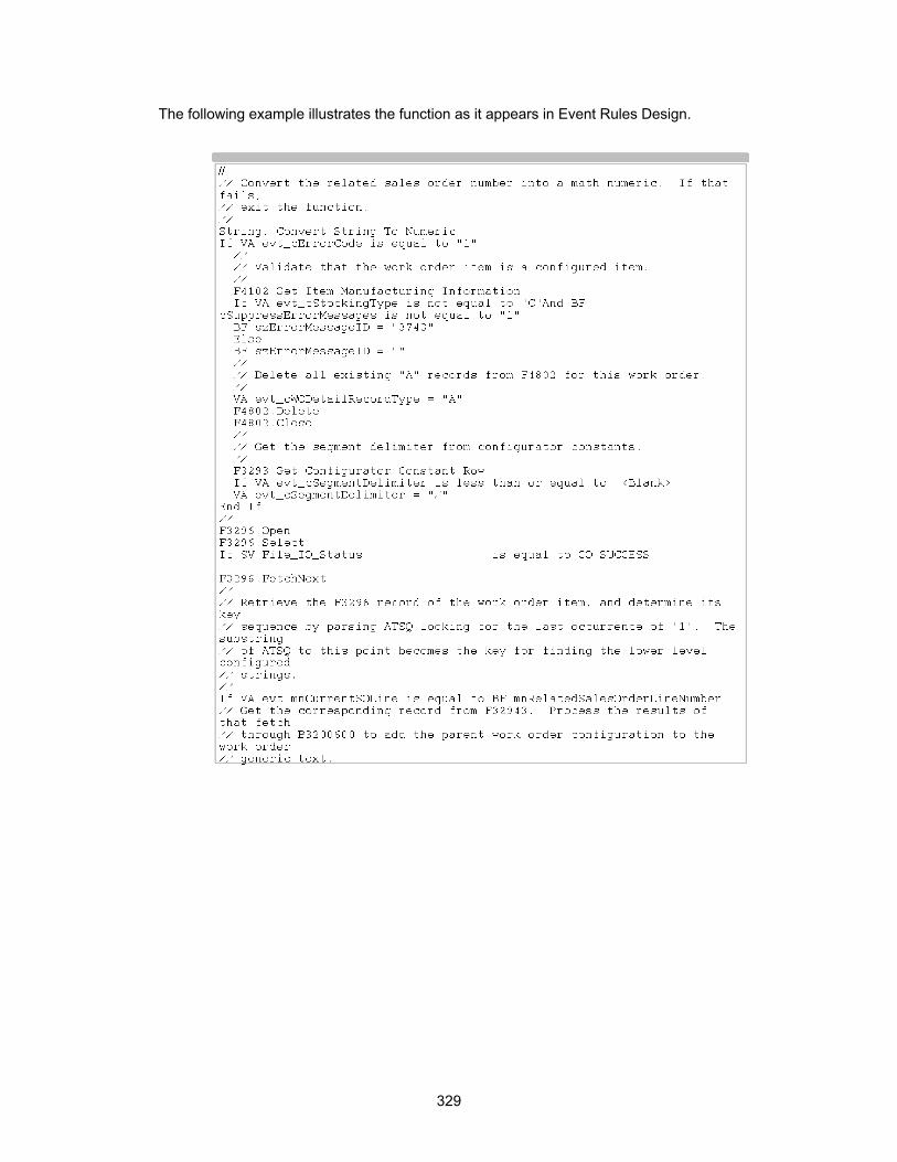
The following example illustrates the function as it appears in Event Rules Design.
329
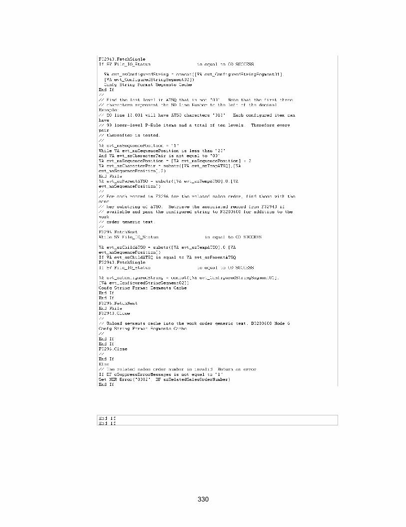
330

Understanding Header File Sections
The following are the major sections of a business function header file:
Section What it Includes Description
Header File Comment
Comments that the input process of the Business Function Source Librarian builds.
The programmer name and SAR number are manually updated by the programmer.
Table Header Inclusions
Include statements for header files associated with tables that are directly accessed by this business function
Table header files include definitions for the fields in a table and the ID of the table itself.
External Business Function Header Inclusions
Include statements for headers associated with externally defined business functions that are directly accessed by this business function
External function calls with jdeCallObject are included to use the predefined data structures.
Global Definitions Global constants used by the business function
Symbolic names that you enter in uppercase, separating words by an underscore. Use sparingly.
Structure Type Definitions
Data structure definitions for internal processing
To prevent naming conflicts, define this structure using structure names that are prefixed by the source file name.
DS Template Type Definition
This structure must be modified through the Object Librarian.
Source Preprocessor
Ensures that the business function declaration and prototype are properly defined for the environment and source file, including this header.
Business Function Prototype
Prototypes for all business functions in the source file
Defines the business functions in the source file, the parameters that are passed to them, and the type of value that they return.
Internal Function Prototype
Prototypes for all internal functions that are required to support business functions within this source file
Defines the internal functions that are associated with the business functions in the source file, the parameters that are passed to each internal function, and the type of value that they return.
• Header file name • Description • History • Programmer • Software Action Request (SAR)
Number • Copyright information
• Data structure type definitions generated by Business Function Design
• Symbolic constants for the data structure generated by Business Function Design
• Undefines JDEBFRTN if it is already defined
• Checks for how to define JDEBFRTN
• Defines JDEBFRTN
331

Business Function Header File Example
Business Function Design created the following header file. It contains the minimum components required in a business function header file.
/*****************************************************************************
* Header File: B98SA001.h
*
* Description: Check for In Add Mode Header File
*
* History:
* Date Programmer SAR# - Description
* ---------- ---------- -------------------------------------------
* Author 03/07/1995 Hotchkiss Unknown - Created
*
*
* Copyright (c) 1994 J.D. Edwards & Company
*
* This unpublished material is proprietary to J.D. Edwards & Company.
* All rights reserved. The methods and techniques described herein are
* considered trade secrets and/or confidential. Reproduction or
* distribution, in whole or in part, is forbidden except by express
* written permission of J.D. Edwards & Company.
****************************************************************************/
#ifndef __B98SA001_H
#define __B98SA001_H
/*****************************************************************************
* Table Header Inclusions
****************************************************************************/
/*****************************************************************************
* External Business Function Header Inclusions
****************************************************************************/
/*****************************************************************************
* Global Definitions
****************************************************************************/
/*****************************************************************************
* Structure Definitions
****************************************************************************/
332
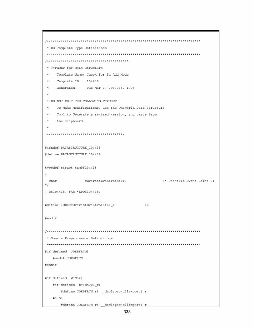
/*****************************************************************************
* DS Template Type Definitions
****************************************************************************/
/*****************************************
* TYPEDEF for Data Structure
* Template Name: Check for In Add Mode
* Template ID: 104438
* Generated: Tue Mar 07 09:33:47 1995
*
* DO NOT EDIT THE FOLLOWING TYPEDEF
* To make modifications, use the OneWorld Data Structure
* Tool to Generate a revised version, and paste from
* the clipboard.
*
**************************************/
#ifndef DATASTRUCTURE_104438
#define DATASTRUCTURE_104438
typedef struct tagDS104438
{
char cEverestEventPoint01; /* OneWorld Event Point 01 */
} DS104438, FAR *LPDS104438;
#define IDERRcEverestEventPoint01_1 1L
#endif
/*****************************************************************************
* Source Preprocessor Definitions
****************************************************************************/
#if defined (JDEBFRTN)
#undef JDEBFRTN
#endif
#if defined (WIN32)
#if defined (b98sa001_c)
#define JDEBFRTN(r) __declspec(dllexport) r
#else
#define JDEBFRTN(r) __declspec(dllimport) r
333

#endif
#else
#define JDEBFRTN(r) r
#endif
/*****************************************************************************
* Business Function Prototypes
****************************************************************************/
JDEBFRTN(ID) JDEBFWINAPI CheckForInAddMode
(LPBHVRCOM lpBhvrCom, LPVOID lpVoid, LPDS104438 lpDS);
/*****************************************************************************
* Internal Function Prototypes
****************************************************************************/
#endif /* __B98SA001_H */
Header File Line Where Input Description 1. Header File Object Librarian Verify the name of the business function header file.
2. Description Object Librarian Verify the description.
3. History IDE Manually update the modification log with the programmer name and the appropriate SAR number.
4. #ifndef Business Function Design
Symbolic constant prevents the contents from being included multiple times.
5. Table Header Inclusion
Business Function Design
When business functions access tables, related tables are input and Business Function Design generates an include statement for the table header file.
6. External Business Function Header Inclusions
Business Function Design
No external business functions for this application.
7. Global Definitions IDE Constants and definitions for the business function. J.D. Edwards does not recommend using this block. Global variables are not recommended. Global definitions go in .c not .h.
Structure Definitions Data structures for passing information between business functions, internal functions, and database APIs.
8. IDE
334

Header File Line Where Input Description 9. TYPEDEF for Data
Structure Business Function Design
Data structure type definition. Used to pass information between an application or report and a business function. The programmer places it on the Clipboard and pastes it in the header file. Its components include:
#endif, which ends the definition of the data structure type definition and its related information.
Comment Block, which describes the data structure.
Preprocessor Directives, which ensure that the data type is defined only once.
Typedef, which defines the new data type.
#define, which contains the ID to be used in processing if the related data structure element is in error.
10. Source Preprocessor Definitions
Business Function Design
All business function header files contain this section to ensure that the business function is prototyped and declared based on where this header is included.
11. Business Function Prototype
Business Function Design
Used for prototypes of the business function.
12. JDEBFRTN(ID) JDEBFWINAPI CheckForInAddMode
Business Function Design
Business Function Standard
All business functions share the same return type and parameter data types. Only the function name and the data structure number vary between business functions.
Parameters include:
LPBHVRCOM: Pointer to a data structure used for communicating with business functions. Values include an environment handle.
LPVOID: Pointer to a void data structure. Currently used for error processing and will be used for security in the future.
LPDS#####: Pointer to a data structure containing information that is passed between the business function and the application or report that invoked it. This number is generated through Object Librarian.
Parameter names (lpBhvrCom, lpVoid, and lpDS) will be the same for all business functions.
JDEBFRTN(ID)JDEBFWINAPI: All business functions will be declared with this return type. It ensures that they are exported and imported properly.
Internal Function Prototypes
Business Function Design
Internal function prototypes required to support the business functions in this source file
13.
335

Understanding the Structure of a Business Function Source File
The Object Management Workbench builds a template for the business function source file. The business function source file consists of several major sections.
Section What it Includes Description
Source File Comment Block
Built from the information in the Business Function Source Librarian.
Any additional relevant notes concerning the business function source
Document complex algorithms used, how the business functions in the source relate to each other, and so on.
Business Function Comment Block
Business Function Source Code
Source code for the business function
Internal Function Comment Block
Copy these blocks and place the values in the specified sections to describe the internal function. Follow the comment block with internal function source code.
Internal Function Source Code
Source code for the internal function described in the comment block
The business function developer inputs this code, as needed. A populated internal function comment block must precede this code.
• Source file name • Description • History • Programmer
• SAR Number
The programmer manually updates the programmer name and SAR number.
• Date
• Description • Copyright information
Notes Comment Block
• Business function name • Description • Description list of the
parameters
• Function name • Notes • Returns • Parameters
Example: Business Function Source File Check for In Add Mode
Business Function Design created the following source file. It contains the minimum components required in a business function source file. The source code in the Main Processing section is manually entered and varies from business function to business function. All other components are completely generated by Business Function Design.
#include <jde.h>
#define b98sa001_c
/*****************************************************************************
* Source File: B98SA001.c
*
336

* Description: Check for In Add Mode Source File
*
* History:
* Date Programmer SAR# - Description
* ---------- ---------- -------------------------------------------
* Author 03/07/1995 Hotchkiss Unknown - Created
*
* Copyright (c) 1994 J.D. Edwards & Company
*
* This unpublished material is proprietary to J.D. Edwards & Company.
* All rights reserved. The methods and techniques described herein are
* considered trade secrets and/or confidential. Reproduction or
* distribution, in whole or in part, is forbidden except by express
* written permission of J.D. Edwards & Company.
****************************************************************************/
/**************************************************************************
* Notes:
*
**************************************************************************/
#include <B98SA001.h>
/**************************************************************************
* Business Function: CheckForInAddMode
*
* Description: Check for In Add Mode
*
* Parameters:
* LPBHVRCOM lpBhvrCom Business Function Communications
* LPVOID lpVoid Void Parameter - DO NOT USE!
* LPDS104438 lpDS Parameter Data Structure Pointer
*
*************************************************************************/
JDEBFRTN(ID) JDEBFWINAPI CheckForInAddMode (LPBHVRCOM lpBhvrCom, LPVOID lpVoid,
LPDS104438 lpDS)
{
/************************************************************************
* Variable declarations
************************************************************************/
337
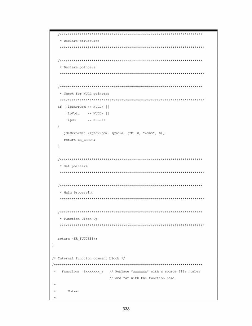
/************************************************************************
* Declare structures
************************************************************************/
/************************************************************************
* Declare pointers
************************************************************************/
/************************************************************************
* Check for NULL pointers
************************************************************************/
if ((lpBhvrCom == NULL) ||
(lpVoid == NULL) ||
(lpDS == NULL))
{
jdeErrorSet (lpBhvrCom, lpVoid, (ID) 0, ”4363”, 0);
return ER_ERROR;
}
/************************************************************************
* Set pointers
************************************************************************/
/************************************************************************
* Main Processing
************************************************************************/
/************************************************************************
* Function Clean Up
************************************************************************/
return (ER_SUCCESS);
}
/* Internal function comment block */
/***************************************************************************
* Function: Ixxxxxxx_a // Replace ”xxxxxxx” with a source file number
// and ”a” with the function name
*
* Notes:
*
338

* Returns:
*
* Parameters:
************************************************************************/
Source File Line Where input Description 1. #include <jde.h> Business Function Design Includes all base OneWorld definitions.
2. #define b98sa001_c
Business Function Design
Ensures related header file definitions are properly made for this source file.
3. Source File Object Librarian Verify the information in the file comment
section. Enter the programmer's name, SAR number, and description.
4. #include <B98SA001.h>
Object Librarian Includes the header file for this application.
5. Business Function
Business Function Design
Verify the name and description in the business function comment block.
6. JDEBFRTN(ID) JDEBFWINAPI CheckForInAddMode (LPBHVRCOM lpBhvrCom, LPVOID lpVoid,
LPDS104438 lpDS)
Business Function Design
Includes the header of a business function declaration.
7. Variable declarations
IDE Declare variables that are local to the business function.
8. Declare structures
IDE Declare local data structures to communicate between business functions, internal functions, and the database.
9. Declare pointers IDE Declare pointers.
10. Check for NULL pointers
Business Function Design
Business Function Standard
Verifies that all communication structures between an application and the business function are valid.
339
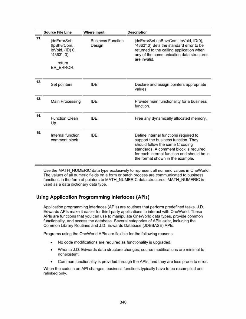
Source File Line Where input Description 11.
jdeErrorSet (lpBhvrCom, lpVoid, (ID) 0, ”4363”, 0);
return ER_ERROR;
Business Function Design
jdeErrorSet (lpBhvrCom, lpVoid, ID(0), "4363",0) Sets the standard error to be returned to the calling application when any of the communication data structures are invalid.
12. Set pointers IDE Declare and assign pointers appropriate
values.
13. Main Processing IDE Provide main functionality for a business
function.
14. Function Clean Up
IDE Free any dynamically allocated memory.
15. Internal function comment block
IDE Define internal functions required to support the business function. They should follow the same C coding standards. A comment block is required for each internal function and should be in the format shown in the example.
Use the MATH_NUMERIC data type exclusively to represent all numeric values in OneWorld. The values of all numeric fields on a form or batch process are communicated to business functions in the form of pointers to MATH_NUMERIC data structures. MATH_NUMERIC is used as a data dictionary data type.
Using Application Programming Interfaces (APIs)
Application programming interfaces (APIs) are routines that perform predefined tasks. J.D. Edwards APIs make it easier for third-party applications to interact with OneWorld. These APIs are functions that you can use to manipulate OneWorld data types, provide common functionality, and access the database. Several categories of APIs exist, including the Common Library Routines and J.D. Edwards Database (JDEBASE) APIs.
Programs using the OneWorld APIs are flexible for the following reasons:
• No code modifications are required as functionality is upgraded.
• When a J.D. Edwards data structure changes, source modifications are minimal to nonexistent.
• Common functionality is provided through the APIs, and they are less prone to error.
When the code in an API changes, business functions typically have to be recompiled and relinked only.
340

Using Common Library APIs
The common library APIs consist of APIs that are specific to J.D. Edwards functionality, such as determining whether foreign currency is enabled, manipulating the date format, retrieving link list information, or retrieving math numeric and date information. You can use these APIs to set up data by calling APIs and modifying data after API calls. Some of the more commonly used categories of APIs include MATH_NUMERIC, JDEDATE, and LINKLIST. Other miscellaneous Common Library APIs are also available.
OneWorld provides two main data types that you use when you create business functions. They are:
• MATH_NUMERIC
• JDEDATE
Because these data types might change, you must use the Common Library APIs provided by OneWorld to manipulate the variables of these data types.
MATH_NUMERIC Data Type
The MATH_NUMERIC data type exclusively represents all numeric values in OneWorld. The values of all numeric fields on a form or batch process are communicated to business functions in the form of pointers to MATH_NUMERIC data structures. MATH_NUMERIC is used as a data dictionary data type.
The data type is defined as follows:
struct tagMATH_NUMERIC
{
char String [MAXLEN_MATH_NUMERIC + 1];
char Sign;
char EditCode;
short nDecimalPosition;
short nLength;
WORD wFlags;
char szCurrency [4];
short nCurrencyDecimals;
short nPrecision;
};
typedef struct tagMATH_NUMERIC MATH_NUMERIC, FAR *LPMATH_NUMERIC;
MATH_NUMERIC Element Description
String The digits without separators.
Sign A minus sign indicates the number is negative; otherwise the value is 0x00.
EditCode The data dictionary edit code that formats the number for display.
nDecimalPosition The number of digits from the right to place the decimal.
341
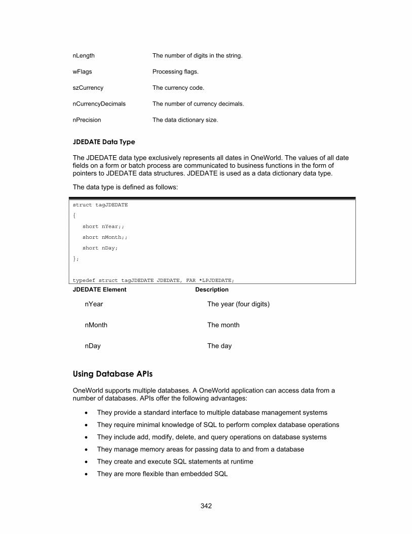
nLength The number of digits in the string.
wFlags Processing flags.
szCurrency The currency code.
nCurrencyDecimals The number of currency decimals.
nPrecision The data dictionary size.
JDEDATE Data Type
The JDEDATE data type exclusively represents all dates in OneWorld. The values of all date fields on a form or batch process are communicated to business functions in the form of pointers to JDEDATE data structures. JDEDATE is used as a data dictionary data type.
The data type is defined as follows:
struct tagJDEDATE
{
short nYear;;
short nMonth;;
short nDay;
};
typedef struct tagJDEDATE JDEDATE, FAR *LPJDEDATE;
JDEDATE Element Description
nYear The year (four digits)
nMonth The month
nDay The day
Using Database APIs
OneWorld supports multiple databases. A OneWorld application can access data from a number of databases. APIs offer the following advantages:
• They provide a standard interface to multiple database management systems
• They require minimal knowledge of SQL to perform complex database operations
• They include add, modify, delete, and query operations on database systems
• They manage memory areas for passing data to and from a database
• They create and execute SQL statements at runtime
• They are more flexible than embedded SQL
342
• They provide an improved method for developing applications in a client/server environment
• They provide standard return codes from function calls
Understanding Standards and Portability
Standards that affect the development of relational database systems are determined by the following:
• ANSI (American National Standards Institute) standard
• X/OPEN (European body) standard
• ISO (International Standards Institute) SQL standard
Ideally, industry standards allow users to work identically with different relational database systems. Although each major vendor supports industry standards, it also offers extensions to enhance the functionality of the SQL language. Vendors are also constantly releasing upgrades and new versions of their products.
These extensions and upgrades affect portability. Due to the industry impact of software development, applications need a standard interface to databases that is not affected by differences between database vendors. When a vendor provides a new release, the impact on existing applications should be minimal. To solve many of these portability issues, many organizations use standard database interfaces called open database connectivity (ODBC).
J.D. Edwards Open Database Connectivity (ODBC)
J.D. Edwards ODBC provides a single access method to multiple relational database management systems. ODBC allows you to use one set of functions to interface with different types of databases. You can develop and compile applications without knowing the type of database that the application uses. Database drivers are installed that allow the J.D. Edwards ODBC interface to communicate with a specific database system.
A driver is an application that processes the API request, communicates with the database, and returns the result to the API. The driver also handles the input/output (I/O) buffers to the database. This allows a programmer to write an application to communicate with a generic data source. The database driver is responsible for processing the API request and communicating with the proper data source. The application does not have to be recompiled to work with other databases. If the application needs to perform the same operation with another database, a new driver is loaded.
A driver manager handles all application requests to the J.D. Edwards database function call. The driver manager processes the request or passes it to an appropriate driver.
The following diagram illustrates how OneWorld uses database APIs.
343

OneWorld applications access data from heterogeneous databases. JDB uses the JDB API to interface between OneWorld applications and multiple databases. OneWorld applications and business functions use the JDB API to dynamically generate platform-specific SQL statements. JDB also supports additional features, such as replication and cross-data source joins.
Standard JDEBASE API Categories
Categories What it Does
Control Level Provides functions for initializing and terminating the database connection.
Request Level Provides functions for performing database transactions. The request level functions perform the following tasks:
Column Level Performs and modifies information for columns and tables.
Global Table/Column Specifications
Provides the capability to create and manipulate column specifications.
• Connect to and disconnect from tables and business views in the database
• Perform data manipulation operations of select, insert, update, and delete
• Retrieve data with fetch commands
You can use control and request level APIs to develop and test business functions.
344

Connecting to a Database
To perform a request, the driver manager and driver must manage the information for the development environment, each application connection, and SQL statement. The pointers that return this information to the application are called handles. The APIs must include these handles in each function call.
Handles used by the development environment include the following:
Handle What it Does
HENV The environment handle contains information related to the current database connection and valid connection handles. Every application connecting to the database must have an environment handle. This handle is required to connect to a data source.
HUSER The user handle contains information related to a specific connection. Each user handle has an associated environment handle with it. A connection handle is required to connect to a data source. If you are using transaction processing, initializing HUSER indicates the beginning of a transaction.
HREQUEST The request handle contains information related to a specific request to a data source. An application must have a request handle before executing a SQL statement. Each request handle is associated with a user handle.
Understanding Database Communication Steps
You can use several APIs to perform the following steps for database communication:
• Initialize communication with the database
• Establish a connection to the specific data to access
• Execute statements on the database
• Release the connection to the database
• Terminate communication with the database
API Level Communication Handles API Name
Control level (application or test driver) Environment handle JDB_InitEnv
Control level (application or test driver) User handle (created) JDB_InitUser
Request level (business function) User handle (retrieved) JDB_InitBhvr
Request level (business function) Request handle JDB_OpenTable
Request handle JDB_FetchKeyed()
Request handle JDB_CloseTable
User handle JDB_FreeBhvr
Control level (application or test driver) User handle JDB_FreeUser
Control level (application or test driver) Environment handle JDB_FreeEnv
345

Calling an API from an External Business Function
To call an API from an external business function, you must first determine the function calling convention of the dll that you are going to use. It can be either cdecl or stdcall. The code might change slightly depending on the calling convention. This information should be included in the documentation for the dll. If you do not know the calling convention of the .dll, you can execute the dumpbin command to determine the calling convention. Execute the following command from the MSDOS prompt window: dumpbin /EXPORTS ExternalDll.DLL. Dumpbin displays information about the dll. If the output contains function names preceded by _ and followed by an @ sign with some numbers, the dll uses the stdcall calling convention; otherwise, it uses cdecl.
Stdcall Calling Convention
The following code example is standard code for windows programs. It is not OneWorld®-specific.
# ifdef JDENV_PC
HINSTANCE hLibrary = LoadLibrary(_TEXT("YOUR_LIBRARY.DLL")); // substitute the name of the external dll
if(hLibrary)
{
// create a typedef for the function pointer based on the parameters and return type of the function to be called. This information can be obtained
// from the header file of the external dll. The name of the function to be called in the following code is "StartInstallEngine". We create a typedef for
// a function pointer named PFNSTARTINSTALLENGINE. Its return type is BOOL. Its parameters are HUSER, LPCTSTR, LPCTSTR, LPTSTR & LPTSTR.
// Substitute these with parameter and return types for your particular API.
typedef BOOL (*PFNSTARTINSTALLENGINE) (HUSER, LPCTSTR, LPCTSTR, LPTSTR, LPTSTR);
// Now create a variable for your function pointer of the type you just created. Then make call to GetProcAddress function with the first
// parameter as the handle to the library you just loaded. The second parameter should be the name of the function you want to call prepended
// with an "_", and appende with an "@" followed by the total number of bytes for your parameters. In this example, the total number of bytes in the
// parameters for "StartInstallEngine is 20 ( 4 bytes for each parameter ). The "GetProcAddress" API will return a pointer to the function that you need to
// call.
346
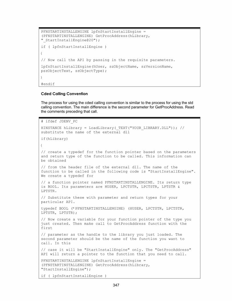
PFNSTARTINSTALLENGINE lpfnStartInstallEngine = (PFNSTARTINSTALLENGINE) GetProcAddress(hLibrary, "_StartInstallEngine@20");
if ( lpfnStartInstallEngine )
{
// Now call the API by passing in the requisite parameters.
lpfnStartInstallEngine(hUser, szObjectName, szVersionName, pszObjectText, szObjectType);
}
#endif
Cded Calling Convention
The process for using the cded calling convention is similar to the process for using the std calling convention. The main difference is the second parameter for GetProcAddress. Read the comments preceding that call.
# ifdef JDENV_PC
HINSTANCE hLibrary = LoadLibrary(_TEXT("YOUR_LIBRARY.DLL")); // substitute the name of the external dll
if(hLibrary)
{
// create a typedef for the function pointer based on the parameters and return type of the function to be called. This information can be obtained
// from the header file of the external dll. The name of the function to be called in the following code is "StartInstallEngine". We create a typedef for
// a function pointer named PFNSTARTINSTALLENGINE. Its return type is BOOL. Its parameters are HUSER, LPCTSTR, LPCTSTR, LPTSTR & LPTSTR.
// Substitute these with parameter and return types for your particular API.
typedef BOOL (*PFNSTARTINSTALLENGINE) (HUSER, LPCTSTR, LPCTSTR, LPTSTR, LPTSTR);
// Now create a variable for your function pointer of the type you just created. Then make call to GetProcAddress function with the first
// parameter as the handle to the library you just loaded. The second parameter should be the name of the function you want to call. In this
// case it will be "StartInstallEngine" only. The "GetProcAddress" API will return a pointer to the function that you need to call.
PFNSTARTINSTALLENGINE lpfnStartInstallEngine = (PFNSTARTINSTALLENGINE) GetProcAddress(hLibrary, "StartInstallEngine");
if ( lpfnStartInstallEngine )
347

{
// Now call the API by passing in the requisite parameters.
lpfnStartInstallEngine(hUser, szObjectName, szVersionName, pszObjectText, szObjectType);
}
#endif
Note These calls work only on a Windows client machine. LoadLibrary & GetProcAddress are Windows APIs. If the business function is compiled on a server, the compile will fail.
Calling a Visual Basic Program from OneWorld
You can call a Visual Basic program from a OneWorld business function and pass a parameter from the Visual Basic program to the OneWorld business function using the following process:
• Write the Visual Basic program into a Visual Basic DLL that exports the function name of the program and returns a parameter to the OneWorld business function.
• Next, write a business function that loads the Visual Basic DLL using the win32 function LoadLibrary.
• In the business function that you create, call the win32 function GetProcAddress to get the Visual Basic function and call it.
Working with Business Functions
Every business function must follow a defined structure and form. Every line of code must conform to the J.D. Edwards business function programming standards. Following these standards allows you to use the following software engineering approach for developing applications:
• Use Object Management Workbench to build business function data structures.
• Use Object Management Workbench to create business function source and header files.
• Create data structure type definitions and add them to the header file.
See Also Creating a Business Function Data Structure
Launching Business Function Design
The following task describes how to access Business Function Design. If you have just created a new business function, skip to step 3 in that task.
► To launch Business Function Design
On Object Management Workbench, check out the business function with which you want to work.
348

1. Ensure that the business function is selected, and then click the Design button in the center column.
The Business Function Design form appears.
2. Click the Design Tools tab, and then click Start Business Function Design Aid.
Viewing Object Codes
Object codes are used to group business functions into categories. You can then use these codes as filters for searches.
► To view object codes
1. From Business Function Design, from the Row menu, choose Codes.
2. Review the following fields:
• Source Module
• Function Name
• Description
• Business Function Category
• Function Use
349

Adding Related Tables and Functions
You can attach both tables and functions to a business function. You must add related tables and functions to the business function object to generate the code for the source and header files.
► To add related tables and functions
1. On Business Function Design, from the Form menu, choose Tables.
2. Enter the names of related tables.
3. Click OK.
► To add related functions
1. On Business Function Design, choose Functions from the Form menu.
2. Enter the names of related business function source objects.
3. Click OK.
The associated record is stored in the Object Librarian - Object Relationships table (F9863).
Debugging Business Functions
Because the source code for business function event rules is generated into C, follow the same procedures for debugging both C and NER business functions. For information about debugging business functions, see Debugging.
Changing a Business Function Parent DLL or Location
You might need to change the parent DLL for a business function.
► To change a business function parent DLL
1. On Business Function Design, type the new DLL name in Parent DLL, or change the business function location and click OK.
2. On Object Librarian Business Function Design, click OK.
3. On Object Management Workbench, check in the business function.
You should transfer this business function to all path codes as soon as possible.
Your change is available to everyone in the next subsequent package.
Creating and Specifying Custom DLLs
Business function DLLs are consolidated. Therefore, you need to build each of your custom business functions into a custom DLL that you create. This process ensures that your custom business functions remain separate from J.D. Edwards business functions. The build program reviews the Object Librarian Master Table (F9860) to verify that your custom DLL exists.
350
Creating a Custom DLL
Before you can build a custom business function into a custom DLL, that custom DLL must exist in the Object Librarian Master Table (F9860). Use this task to create a custom DLL.
► To create a custom DLL
1. On Object Management Workbench, click Add.
2. On Add OneWorld Object to the Project, choose the Business Function Library option, and then click OK.
3. On Add Object, complete the following fields and click OK.
• Object Name
• Description
• Product Code
• Product System Code
• Object Use
Specifying a Custom DLL for a Custom Business Function
When you create a custom business function, you need to specify one of your custom DLLs; otherwise, the build process builds the custom business function into the J.D. Edwards CCUSTOM.DLL, which is the default. Use this task to specify a custom DLL when you create a custom business function.
► To specify a custom DLL for a custom business function
1. Enter your custom DLL name in the Parent DLL field, and click OK. (This form also allows you to change the business function location, if necessary.)
2. Run the build for the business function.
351

Working with Business Function Builder
You use Business Function Builder to build business function code into a dynamic link library (DLL). You can build C business functions, named event rules, and table event rules.
The process that occurs when you build business functions includes compiling and linking. Compiling involves creating a business function object. Linking makes the object part of a DLL.
Understanding the Business Function Builder Form
The Business Function Builder form consists of the following three main components:
• Functions List
• Available Business Functions
• Build Output
In addition to these components, a status window also appears at the bottom of the Business Function Builder form, and it displays the status of builds as they are in progress. You can click the Stop button in the status bar to discontinue a build.
The combo box in the Toolbar should be set in the Optimize mode. If you are debugging, the box should be set to Debug mode.
352
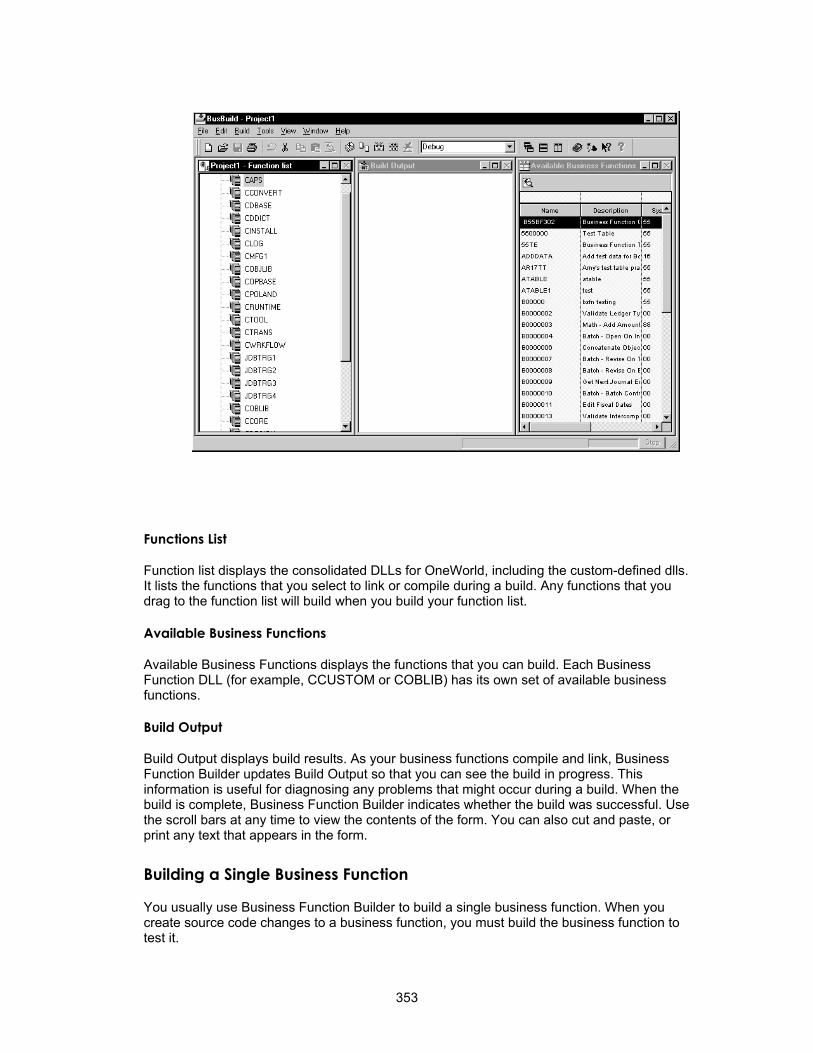
Functions List
Function list displays the consolidated DLLs for OneWorld, including the custom-defined dlls. It lists the functions that you select to link or compile during a build. Any functions that you drag to the function list will build when you build your function list.
Available Business Functions
Available Business Functions displays the functions that you can build. Each Business Function DLL (for example, CCUSTOM or COBLIB) has its own set of available business functions.
Build Output
Build Output displays build results. As your business functions compile and link, Business Function Builder updates Build Output so that you can see the build in progress. This information is useful for diagnosing any problems that might occur during a build. When the build is complete, Business Function Builder indicates whether the build was successful. Use the scroll bars at any time to view the contents of the form. You can also cut and paste, or print any text that appears in the form.
Building a Single Business Function
You usually use Business Function Builder to build a single business function. When you create source code changes to a business function, you must build the business function to test it.
353
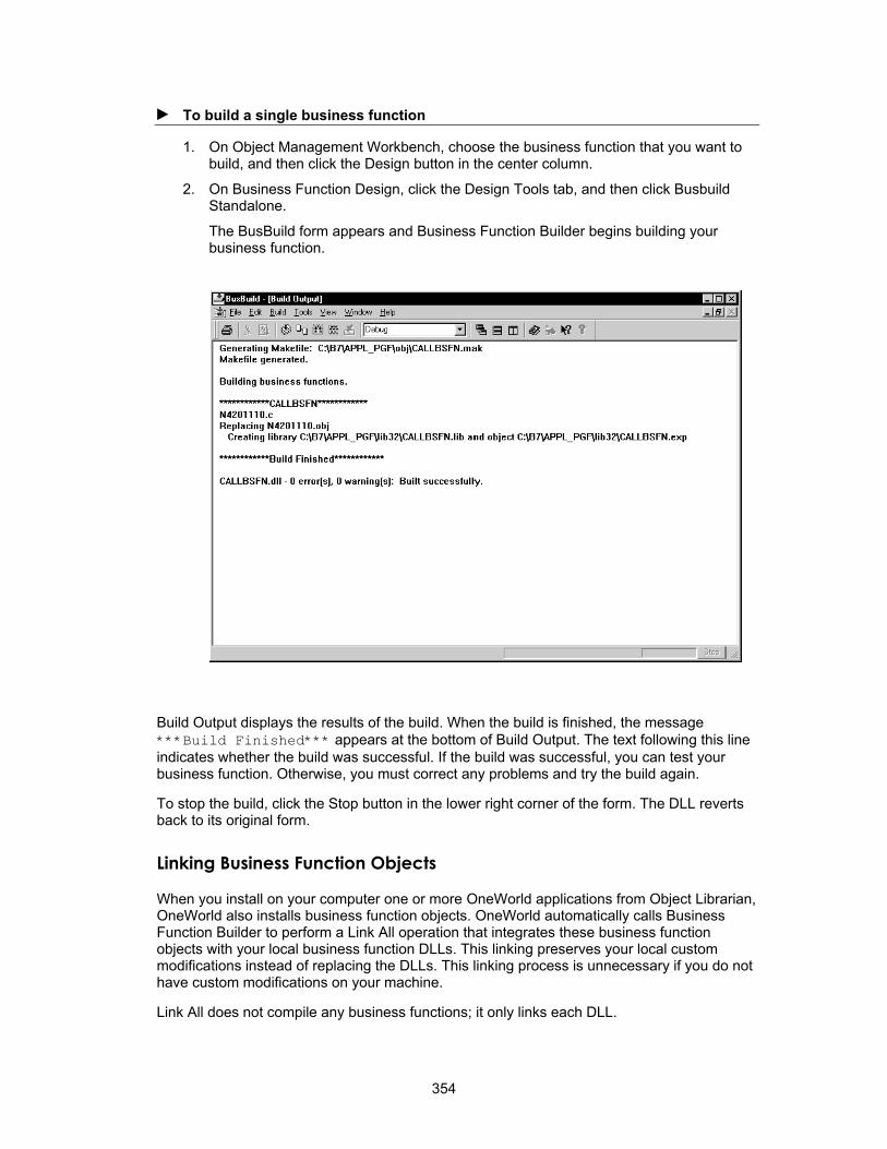
► To build a single business function
1. On Object Management Workbench, choose the business function that you want to build, and then click the Design button in the center column.
2. On Business Function Design, click the Design Tools tab, and then click Busbuild Standalone.
The BusBuild form appears and Business Function Builder begins building your business function.
Build Output displays the results of the build. When the build is finished, the message ***Build Finished*** appears at the bottom of Build Output. The text following this line indicates whether the build was successful. If the build was successful, you can test your business function. Otherwise, you must correct any problems and try the build again.
To stop the build, click the Stop button in the lower right corner of the form. The DLL reverts back to its original form.
Linking Business Function Objects
When you install on your computer one or more OneWorld applications from Object Librarian, OneWorld also installs business function objects. OneWorld automatically calls Business Function Builder to perform a Link All operation that integrates these business function objects with your local business function DLLs. This linking preserves your local custom modifications instead of replacing the DLLs. This linking process is unnecessary if you do not have custom modifications on your machine.
Link All does not compile any business functions; it only links each DLL.
354

Reviews the selected business function for ANSI compatibility.
Build All
Setting Build Options
You can use options on the Build menu to control how and when your consolidated business function is built. The following options are available:
Build Generates a makefile, compiles the selected business functions, and links the functions into the current consolidated DLL. Rebuilds only out-of-date components.
Compile Generates a makefile and compiles the selected business functions. The application does not link the functions into the current consolidated DLL.
ANSI Check
Link Generates a makefile for each consolidated DLL. It then builds each consolidated DLL. The application does not compile any of the selected business functions.
Link All Generates a makefile for each consolidated DLL. It then builds each consolidated DLL and links it to all business functions that are called. The application does not compile any of the selected business functions.
Rebuild Libraries
Rebuilds the consolidated DLL and static libraries from the .obj files.
Links and compiles all objects within each DLL.
Stop Build Stops the build from finishing. The existing consolidated DLL remains intact.
Suppress Output
Limits the text that appears in Build Output.
355

Browse Info Generates browse information when compiling business functions. Turn this option off to expedite the build.
Precompiled Header
Creates a precompiled header when compiling a business function. When compiling multiple business functions, the Business Function Builder generally compiles faster if it uses a precompiled header.
Debug Info Generates debug information when compiling. The Visual C++ can debug any function that was built with debug information. Turn this option off to expedite the build.
Full Bind Resolves all of the external runtime references for each OneWorld consolidated DLL.
Using Utility Programs
The Tool menu contains utility programs that assist in the build process. These programs include:
Synchronize JDEBLC
You can run this utility to reorganize OneWorld business functions into new DLL groupings. This utility synchronizes DLL field for the local JDEBLC parent specification table with the parent DLL in the Object Librarian Master Table (F9860). Use this option with caution. You typically use this option only if you have manually dragged business function DLLs from a recent package build and you are experiencing failures in the business function load library.
Dumpbin You can run this utility to verify whether a particular business function built successfully. This utility displays all the business functions that were built into the selected consolidated DLL.
PDB Scan You receive a CVPACK fatal error when one of the object files that you are trying to link is incorrectly compiled with PDB information. To resolve this problem, you can use the PDB scan to identify any object fields that were built with PDB information. Recompile any business functions that the PDB scan reports.
Reading Build Output
Build Output consists of a series of sections that display important information about the status of a build. You can use this output to determine whether your build completed successfully and to troubleshoot problems if errors occur during your build.
The following figure is an example of the messages that the system generates during a build.
356

Makefile Section
The makefile section indicates where Business Function Builder generated the makefile for this build. Business Function Builder generates one makefile for each DLL that it builds. A Generating Makefile statement should always appears for each DLL that you are building. If the makefile statement does not appear, then an error occurred. To resolve the error:
• Verify that the local object directory exists.
• Verify that the permissions for the local object directory and the makefile are correct.
Begin DLL Section
Begin DLL indicates that Business Function Builder is building a particular DLL. For example, the section above begins with *****CDIST*****. A Begin DLL section appears for each DLL that you are building.
Compile Section
In order to build DLLs, Business Function Builder compiles the business functions in the DLLs first. The system displays a sequential list of each business function that the Business Function Builder attempts to compile. During the compilation process, the following might occur:
• Compiler Warning
When a compiler warning occurs, Business Function Builder displays warning CXXXX (where XXXX is a number) and a brief description of the warning. To review information about the warning, search for the CXXXX value in Visual C++ helps.
357

Warnings usually do not prevent the business function from compiling successfully. You can turn on the Warnings As Errors option in the Global Build form so that the business function will not build if any warnings occur.
• Compiler Error
When a compiler error occurs, Business Function Builder displays error CXXXX (where XXXX is a number) and a brief description of the error. To review extended information about the error, search for the CXXXX value in Visual C++ helps. Errors prevent the business function from compiling successfully, so you must resolve them.
Link Section
After Business Function Builder has compiled the business functions for a DLL, it links them. This linking process creates the .lib and .dll files for the DLL. During linking, the following might occur:
• Linker Warning
When a linker warning occurs, Business Function Builder displays warning LNKXXXX (where XXXX is a number) and a brief description of the warning. To review information about the warning, search for the LNKXXXX value in the Visual C++ helps. Warnings usually do not prevent the business function from linking successfully. You can turn on the Warnings As Errors option in the Global Build form so that the DLL will not build if it has any warnings occur.
• Linker Error
When a linker error occurs, Business Function Builder displays error LNKXXXX (where XXXX is a number) and a brief description of the error. To review extended information about the error, search for the LNKXXXX value in the Visual C++ helps. If a nonfatal error occurs, Business Function Builder still creates the DLL. However, Business Function Builder notes that the DLL was built with errors. If a fatal error occurs, Business Function Builder does not build the DLL.
Rebase Section
The Rebase Section displays information about rebasing. Rebase fine tunes the performance of DLLs so that they load faster. It does this by changing the desired load address for the DLL so that the system loader does not have to relocate the image. It automatically reads the entire DLL and also updates fixes, debug information, checksum information, and time stamp values.
Summary Section
The Summary Section contains the most important information about the build. This section indicates whether the build is successful. The summary section begins with "*****Build Finished*****". Next Business Function Builder displays a summary report for each DLL that you attempted to build. This report includes the following:
• The number of warnings
• The number of errors
• Whether the DLL build is successful
358

Building All Business Functions
A system administrator usually performs Build All. Build All processes can take a long time. Build All not only does what the global link does, but it also recompiles all of the objects within each DLL. To run Build All, you must access BusBuild from the OneWorld Explorer menu.
► To build all business functions
1. On Object Management Workbench, choose the business function that you want to build, and then click the Design button in the center column.
2. On Business Function Design, click the Design Tools tab, and then click Busbuild Standalone.
The BusBuild form appears.
3. On BusBuild, from the Build menu, choose Build All.
359
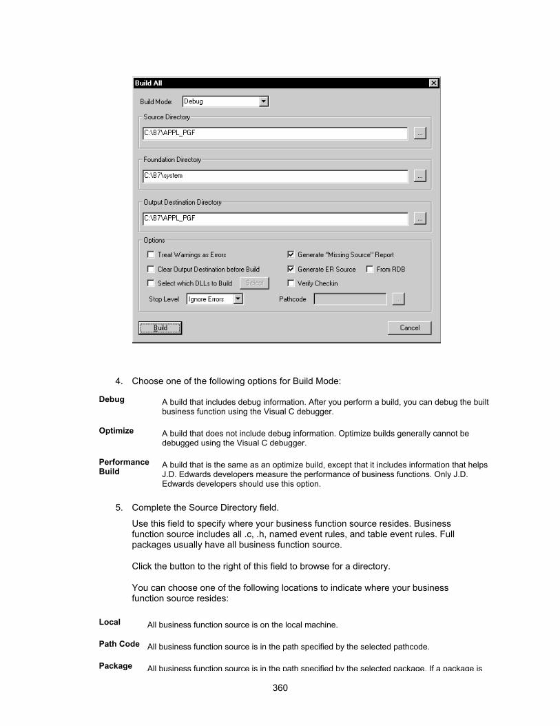
4. Choose one of the following options for Build Mode:
Debug A build that includes debug information. After you perform a build, you can debug the built business function using the Visual C debugger.
Optimize A build that does not include debug information. Optimize builds generally cannot be debugged using the Visual C debugger.
Performance Build
A build that is the same as an optimize build, except that it includes information that helps J.D. Edwards developers measure the performance of business functions. Only J.D. Edwards developers should use this option.
5. Complete the Source Directory field.
Use this field to specify where your business function source resides. Business function source includes all .c, .h, named event rules, and table event rules. Full packages usually have all business function source.
Click the button to the right of this field to browse for a directory.
You can choose one of the following locations to indicate where your business function source resides:
Local All business function source is on the local machine.
Path Code All business function source is in the path specified by the selected pathcode.
Package All business function source is in the path specified by the selected package. If a package is
360

built correctly, it typically contains all required business function source. Package is the recommended location.
Pick Directory
All business function source is stored in another directory of your choice that exists on your file server.
For example, suppose that you have a package called PROD_A that physically resides on the file server location \\SERVER\SHARE1\PROD_A. PROD_A contains the following subdirectories:
Source Contains all business function .c
Include Contains all business function .h
Spec Contains all spec files
For this configuration on the server for PROD_A, click the button, then Package, then PROD_A from the detail area. When Business Function Builder builds, it uses the business function source from this directory.
6. Complete the Foundation Directory field.
Use this field to specify the foundation to use for this build. The foundation that you select is the foundation on which you expect these business functions to run.
Click the button to the right of this field to browse for a location.
You can select your foundation from one of the following locations:
Local The desired foundation is the local OneWorld foundation.
Foundation The foundation table lists all registered OneWorld foundations. Choose a foundation from this table.
Pick Directory
The OneWorld foundation exists on your file server in a directory of your choice. This is the recommended choice for this option.
For example, suppose you have a newly built foundation on the server at location \\SERVER\SHARE1\System\New\Optimize. This directory contains the following subdirectories:
Lib32 Contains all foundation .lib
Include Contains all foundation .h
Includev Contains all vendor .h
7. Complete the Output Destination Directory field.
Use this field to specify the location for the output of the build. The build output includes the following file types: DLL, .LIB, .OBJ, .LOG.
Click the button to the right of this field to browse for a location.
361

You can select one of the following locations for your output destination directory:
Local All business function output is stored on the local machine.
Path Code All business function output is stored in the path specified by the selected pathcode. The pathcode contains the latest business function changes that have been checked in.
Package All business function output is stored in the selected package. Package is a more stable snapshot of business function source. Package is the recommended location.
Pick Directory
All business function output is stored in a directory of your choice on your file server.
For example, suppose that you have a package called PROD_A that is located on the file server at \\SERVER\SHARE1\PROD_A. When the build finishes, you want Business Function Builder to place the build output in the following subdirectories that are subordinate to PROD_A:
Bin32 Contains built .dll files
Lib32 Contains build .lib files
Obj Contains built .obj files
Work Contains built .log files
With the above configuration on the server for PROD_A, click the button, then Package, then choose PROD_A from the detail area. When Business Function Builder builds, it places the build output files in these subdirectories for PROD_A.
8. Click any of the following Options:
Treat Warnings As Errors
If you turn on this option, Business Function Builder does not build a business function if it contains any warnings.
Clear Output Destination Before Build
If you turn on this option, Business Function Builder deletes the contents of the bin32, lib32 and obj output directories before it builds all business functions.
Select Which DLLs to Build
If you do not turn on this option, Business Function Builder builds all DLLs. If you turn on this option, you can click the Select button to choose which business function DLLs you want to build. Use this option if you want to build one or two DLLs. If you build only a subset of all DLLs, then verify that the Clear Output Destination Before Build option is turned off.
Stop Level You can select the error level at which the build stops. You can ignore errors to continue building despite errors. You can stop if a DLL contains errors. You can stop on the first compile error.
Generate "Missing Source" Report
If you turn on this option, Business Function Builder creates a report in the work directory of the destination. This directory is called NoSource.txt. It contains business function source file names that do not have a .c file but do have a record in the Object Librarian Master Table (F9860). To clean this report, you can produce the correct .c file for the business function, or you can delete the source file from the F9860 table. This option is recommended.
Generate ER Source
If you turn on this option, Business Function Builder generates named event rule and table event rule source prior to building business functions.
362
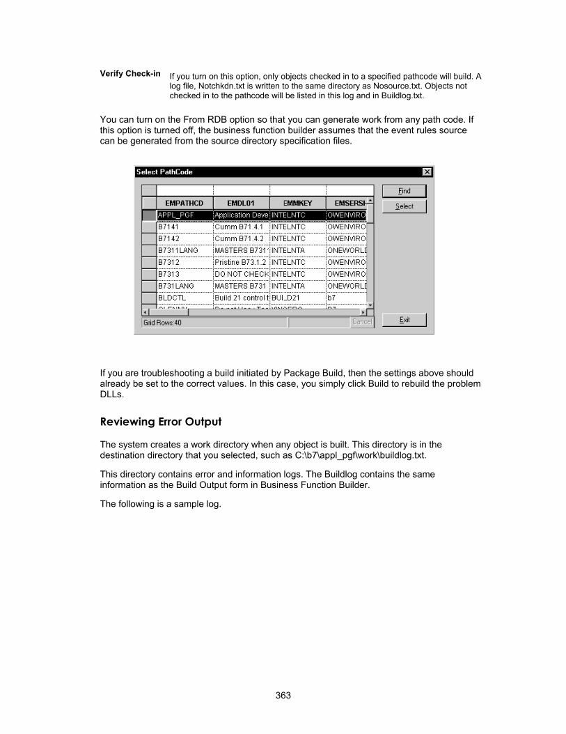
Verify Check-in If you turn on this option, only objects checked in to a specified pathcode will build. A log file, Notchkdn.txt is written to the same directory as Nosource.txt. Objects not checked in to the pathcode will be listed in this log and in Buildlog.txt.
You can turn on the From RDB option so that you can generate work from any path code. If this option is turned off, the business function builder assumes that the event rules source can be generated from the source directory specification files.
If you are troubleshooting a build initiated by Package Build, then the settings above should already be set to the correct values. In this case, you simply click Build to rebuild the problem DLLs.
Reviewing Error Output
The system creates a work directory when any object is built. This directory is in the destination directory that you selected, such as C:\b7\appl_pgf\work\buildlog.txt.
This directory contains error and information logs. The Buildlog contains the same information as the Build Output form in Business Function Builder.
The following is a sample log.
363
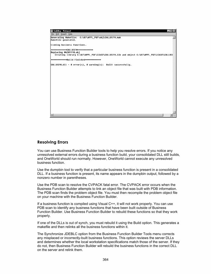
Resolving Errors
You can use Business Function Builder tools to help you resolve errors. If you notice any unresolved external errors during a business function build, your consolidated DLL still builds, and OneWorld should run normally. However, OneWorld cannot execute any unresolved business function.
Use the dumpbin tool to verify that a particular business function is present in a consolidated DLL. If a business function is present, its name appears in the dumpbin output, followed by a nonzero number in parentheses.
Use the PDB scan to resolve the CVPACK fatal error. The CVPACK error occurs when the Business Function Builder attempts to link an object file that was built with PDB information. The PDB scan finds the problem object file. You must then recompile the problem object file on your machine with the Business Function Builder.
If a business function is compiled using Visual C++, it will not work properly. You can use PDB scan to identify any business functions that have been built outside of Business Function Builder. Use Business Function Builder to rebuild these functions so that they work properly.
If one of the DLLs is out of synch, you must rebuild it using the Build option. This generates a makefile and then relinks all the business functions within it.
The Synchronize JDEBLC option from the Business Function Builder Tools menu corrects any misplaced or incorrectly-built business functions. This option reviews the server DLLs and determines whether the local workstation specifications match those of the server. If they do not, then Business Function Builder will rebuild the business functions in the correct DLL on the server and relink them.
364

The Build Log contains the following sections:
Build Header
The build header shows the configuration for a specific build, including the source path, foundation path, and destination path.
The last section of the build summarizes the build for each DLL. This summary is in the form x error(s), x warnings (y). The summary indicates how the status of the build. If you have no warnings and no errors, then the build was successful. If the summary reports an error, search the log for the word error to determine the source of the error. Typical build errors are syntax errors and missing files.
Build Messages
The build messages section displays the compile and link activity. During a compile, a line is output for each business function that was compiled Any compile errors are reported as error cxxxx. During the link part, business function builder outputs the text Creating library .... This text might be followed by linker warnings or errors.
Build Summary
Transaction Master Business Functions
Transaction master business functions provide a common set of functions that contain all of the necessary defaulting and editing for a transaction file. Records depend on one another. They contain logic that ensures the integrity of the transaction being inserted, updated, or deleted from the database. Event flow brakes up logic. You use cache APIs to hold records being processed. You should consider using a transaction master business function in the following situations:
• You accept transaction file records from a non-J. D. Edwards source
• Multiple applications are updating the same transaction file
For example:
• The Account Ledger table (F0911) accepts updates across product lines, as well as external sources.
• The Employee Transaction Detail File table (F06116) accepts updates from batch, interactive, and external sources.
Master Business Function Naming Convention
The Master Business Function source is named Bxxxxxxxx (the same as any other business function), unless the object already exists on the AS/400 as a functional server. In this case, the XTXXXXZ1 naming convention is used. Within this source are external business functions for each of the modules.
The data structure name for each module is DxxxxxxxxA,B,C and so on. (Examples include B0400047 - D0400047A [Begin Document], D0400047B [Edit Line], D0400047C [Edit Document], D0400047D [End Document].)
The format for naming individual business functions is file-name module-name. Document is shortened to Doc. (An example of a business function name is F0411BeginDoc.)
The functional use code of 192 designates business functions as master business functions.
A cache tracks transaction records. It has the naming convention FxxUIyyy, where:
xx is the system code
yyy is a unique number
365

Creating Processing Options for a Master Business Function
A Master Business Function (MBF) can be called from several different applications. Rather than duplicating the processing options for the MBF on each application, create a separate processing option template for these processing options.
► To create processing options for a Master Business Function
1. Create a processing option template.
The format for the name of the processing option template is Txxxxxxxx (replace the B or XT in the MBF name with a T).
2. Create an artificial application for attaching the MBF processing options.
You can then set up different versions of the MBF processing options through the versions list. The naming convention for this artificial application is Pxxxxxxxx (replace the B or XT in the MBF name with a P). To generate, this application needs only one form with no fields selected.
You can use interactive versions to set up different versions of the master business function processing options. Calling programs then pass the version name to the version parameter of BeginDoc.
From within BeginDoc, the business function AllocatePOVersionData can be called to retrieve the processing options by version name. The processing options needed by other modules can be written to the header cache and accessed later, rather than calling AllocatePOVersionData multiple times.
Refer to the online APIs for more information.
Naming Transaction Master Business Function Modules
Function names follow the standard naming convention Fxxxxx. If a table has multiple master business functions, include the program name in the function name.
FxxxxxProgram Name Module
For example:
• F3112SuperBackFlushBegDoc
• F3112WorkOrderRoutingsBegDoc
366

Components of a Transaction Master Business Function
You typically use the following basic components for a master business function:
Begin Document
Called when all header information has been entered
Edit Line Called when all line information has been entered
Edit Document Called when ready to commit the transaction
End Document Called when you need to commit the transaction
Clear Cache Called when you are ready to delete all cache records
• Creates initial header if it has not already been created • Can also include defaulting, editing, and processing options
• Creates cache for detail information if it has not already been created
• Processes any last document edits and verifies that all records are valid to commit
• Processes all records in the header and detail cache and performs I/O and deletes caches
• Deletes header and detail cache records
Begin Document
Function Name FxxxxxBeginDocument
What Does It Do?
• Inserts default information and edits information in the header. This includes data dictionary defaults, edits, and UDC editing.
• Fetches information from the database, if necessary, to validate that the selected document action can take place.
• Validates and processes information that is common to all records.
• Writes the record to header cache if no errors exist.
• Contains all header cache information that is common to all detail records. This improves performance by eliminating the need to use all the detail records to perform the same validations and table I/O.
• Updates the header cache with the new information when information in the header fields changes and Begin Document has been called previously.
Special Logic/Processing Required On the initial call, the function assigns the job number. To retrieve the job number, this function calls X0010GetNextNumber with a system code of 00 and an index number of 04. If Begin Document is called again, it passes the job number was previously assigned; therefore, it does not need to assign another job number.
Hook-Up Tips
• You must call a function at least once before calling Edit Line.
367

• If errors occur during validation of the header field when the function is called, call the function again to verify that errors have been cleared before calling Edit Line.
• If this function might be called multiple times from different events, include it on a hidden button on an application to reduce duplicate code and ensure consistency. This button might then be called from focus on grid because the user is then adding or deleting detail records, and is finished adding header information. In case of a Copy in which the user does not use the grid, this button might also be called on OK button.
• Calling a button from an asynchronous event breaks the asynchronous flow and forces the button to be processed in synchronous mode (inline).
Common Parameters
Name Alias I/O Description
Job Number JOBS I/O Pass Job Number created in BeginDocument, if previously called; otherwise, pass zeros and assign a job number.
Document Action ACTN I A or 1 = Add
C or 2 = Change
D = Delete
This is the action of the entire Document, not the individual detail lines. For example, you might modify a few detail lines in Edit Line, add a few detail lines in Edit Line, and delete a few detail lines in Edit Line, but the Document Action in Begin Document would be Change.
Process Edits EV01 I Optional
0 = No Edits
Any Other = Full Edits
Note The GUI interface usually uses the partial edit, and the batch interface uses the full. If blank, the default option is full edits.
ErrorConditions EV02 O Blank = No Errors
1 = Warning
2 = Error
Version VERS I This field is required if this MBF is using versions.
Header Field One **** I/O Pass in all the header fields that are common to the entire document. Begin Document processes all of these fields and validates them, Data Dictionary edits, UDC editing, default values, and so on. Begin document might also fetch to the table to validate that records matching these header fields exist for Delete and Change, or do not exist for Add.
368

Header Field Two **** I/O
.
.
.
**** I/O
Header Field XX **** I/O
Work Field / Processing Flag One
**** I List any work fields that the program needs. These could be flags for processing, dates to validate, and so on. These fields might or might not be used. For example, currency control might be saved in the header cache so that all detail records would either use currency or not.
Work Field / Processing Flag One
**** I
.
.
.
I
Work Field / Processing Flag One
I
Application-Specific Parameters
• List the fields needed to process header level information.
• List any work fields needed to perform edits.
• List all processing options needed to process header level information.
Edit Line
Function Name FxxxxxEditLine
What Does It Do?
• Validates all user input, performs calculations, and retrieves default information. Edit Line normally is called for every record that is fetched and performs the edits for that one record in the file.
• Reads header cache records for default values.
• On an ADD, enters default information in blank columns, such as Address Book information. The default values might come from any of the following:
• Another column in the line
• A process performed on a column sent in the line
• A processing option
• A saved value from the header record that was determined in the Begin Document module
369

• A data dictionary default value
• Edits columns for correct information. This includes interdependent editing between columns. Also performs UDC and data dictionary edits are performed.
• Writes record to the detail cache if no errors occured. If the record already exists in the work file, the line in the work file will be retrieved and updated with the changes. If a record is deleted from the grid in direct mode, and the record does not exist in the database, the record will be removed from the detail cache. If the record exists in the database, the action code for the record will be changed to delete, and the record will be stored in the detail cache until file processing in End Doc.
Special Logic/Processing Required The following special processing occurs:
• Depending on the type of document being processed, different editing and inserting of default values takes place. An example would be vouchers and invoices processed through the journal entry MBF. The tax calculator is only called for vouchers.
• Depending on the event processing required, the process edit flag determines the editing that occurs. For example, in an interactive program, when the Grid Record is Fetched event runs, Partial Edits might be performed to retrieve descriptions, default values, and so on. When the Row is Exited and Changed event runs, Full Edits might be performed to validate all user input.
Typical Uses and Hookup
Interactive Grid Record is Fetched
Row is Exited and Changed (Asynch)
Batch Do section of the group, columnar, or tabular section.
Common Parameters
Name Alias I/O Description
Job Number JOBS I Used as key or to create a unique name for the cache or work file. Retrieved from Begin Document.
Line Number LNID I/O The unique number identifying the transaction line. Can also be used as the line number in the Detail Cache.
Line Action ACTN I A or 1 = Add
C or 2 = Change
D or 3 = Delete
Process Edits (optional)
EV01 I 0 = No Edits
1 = Full Edits
2 = Partial Edits
Note
GUI interface typically uses the partial edit, and the batch interface typically uses the full edit. If blank, the default edit is Full.
370

Error Conditions ERRC O 0 = No Errors
1 = Warning
2 = Error
Update Or Write to Work File
EV02 I 1 = Write and/or Update records to the work file.
Record Written to Work File
EV03 I/O 1 = A record is written to the work file. This reduces I/O calls to the work file.
Blank = No record was written to the work file.
Detail Field One **** I/O Pass in all the Detail fields that will be edited. Typically, these are the gird record fields. Edit Line provides validation, Data Dictionary edits, UDC editing, defaults, and so on.
Detail Field Two **** I/O
Detail Field XX **** I/O
Work Field / Processing Flag One
**** I List any work fields that the program needs. These fields could be flags for processing, dates to validate, and so on.
Work Field / Processing Flag One
**** I
Work Field / Processing Flag One
I
Edit Document
What Does It Do?
• Reads cache records if multiple line editing is required
• Read header cache record if header information is needed
• Performs cross-dependency edits involving multiple lines in document. For example, Edit Document processes all records to ensure that percentages total 100 percent, and it validates that the last record does not contain certain information.
Special Logic/Processing Required Depending on the type of document that you are processing, different logic is executed. For example, vouchers and invoices are processed through the journal entry edit object, although the balancing is different for these document types.
Hook Up Tips
• Call the function at least once after calling Edit Line and before End Document.
• If errors occur during validation, call the function again to verify that errors have been cleared before calling End Document.
• Call this function on the OK button clicked event so that, if errors occur, they are corrected before the user exits the application.
371
Common Parameters
Name Alias I/O Description
Job Number JOBS I Was retrieved from Begin Document
ErrorConditions EV01 O Blank = No Errors
1 = Warning
2 = Error
Application-Specific Parameters Because all records have been added in Begin Document or Edit Line, and because any information needed to process the entire document is in cache, a minimum number of parameters are needed in this function.
End Document
Function Name FxxxxxEndDocument
What Does It Do?
• Assigns a next number to the document. For vouchers, you should do this before calling journal entry edit object, but not before the voucher has been balanced and is ready to be added to the database. By placing this module on the before add/delete/update event, the document passes all edits before running this event.
• Reads cache records.
• On an ADD, writes new rows to the table.
• On a CHG, retrieves and updates existing rows.
• On a DEL, deletes rows from the table.
• Adds information and updates associated tables. For example, it adds and updates the following:
• Manual checks associated with Vouchers
• Address Book vouchered YTD columns in Address Book
• Address, phones, and who's who information for Address Book
• Batch header
• After all updates complete successfully, clears the cache for that document and any work fields.
• Summarizes documents, if designated in a processing option, as it writes to the database. Reads work file through an alternate means and write the records at a control break.
• Performs currency conversion.
Special Logic/Processing Required No special logic or processing is required.
372

Hook-Up Tips This function is typically called on OK button Post Button Clicked, and it is hooked up Asynch. In the C code, after the insert or update to the database is successful, call Clear Cache to clear the cache.
Common Parameters
Name Alias I/O Description
Job Number JOBS I Was retrieved from Begin Document
Computer ID CTID I Retrieved from GetAuditInfo(B9800100) in application (optional)
Error Conditions EV01 O Blank = No errors
1 = Warning
2 = Error
Program ID PID I Usually hard-coded
Application-Specific Parameters
• List the fields needed to process update or writes, such as Time and Date Stamp fields.
• List any work fields needed to perform updates or writes.
• List all processing options needed to process updates or writes.
Clear Cache
Function Name FxxxxxClearCache
What Does It Do? Removes the records from the header and detail cache
Special Logic/Processing Required If a unique cache name is selected as the naming convention for the cache (Dxxxxxxxx [Job Number]), then use the cache API jdeCacheTerminateAll to destroy the cache.
Common Parameters
Name Alias I/O Description
Job Number JOBS I Indicates the job number of the transaction that you want to clear. This job number should have been returned from BeginDoc.
Clear Header EV01 I Indicates whether the header cache should be cleared.
1 = clear cache
Clear Detail EV02 I Indicates whether the detail cache should be cleared
1 = clear cache
Line Number From
LNID I Indicates where to begin clearing records in the detail cache. If this line is blank, the system begins clearing from the first record
373

From (Optional)
the system begins clearing from the first record.
Line Number Thru (Optional)
NLIN I Indicates where to stop clearing records in the detail cache. If this line is blank, the system deletes to the end of the cache.
Cancel Document (optional)
Function Name FxxxxxxCancelDoc
What Does It Do? Used primarily with the Cancel button to close files, clear the cache, and so on. Cancel Document is an application-specific function that provides basic function cleanup.
Special Logic/Processing Required This is an application-specific function.
Common Parameters
Name Alias I/O Description
Job Number
JOBS I The job number of the transaction that you want to clear. This job number should have been returned from BeginDoc.
Cache Structure
The cache structure stores all lines of the transaction. Transaction lines are written to the cache after they have been edited. The EndDoc module then reads the cache to update the database.
The cache structure layout is as follows:
Header
Field Description Field Key Type Size Job Number JOBS X Num
Document Action ACTN Char 1
Processing Options
Currency Flag CYCR Char 1
Business View Fields
Work Fields
Job Number A unique job number assigned when the job is started by the BeginDoc module. This distinguishes transactions in the cache for each job on the workstation that is using the cache. Use next number 00/4 for the job number. If you are using a unique cache name (Dxxxxxxxxx [job number]), you do not necessarily need the job number field stored in the cache for a key because you would only be working with one transaction per cache You
374
can, therefore, use any field as the key to the cache.
Document Action
The action for the document. Valid values are:
A or 1 = Add
C or 2 = Change
D = Delete
Processing Options
Processing option values were read in using AllocatePOVersionData, and are needed in other modules of the MBF.
Currency Flag
A system value that indicates whether currency is on and what method of currency conversion is used (N, Y, or Z).
Business View Fields
The fields required for processing the transaction and writing it to the database. All fields in the record format that are not saved in the header cache will be initialized when the record is added to the database using the APIs.
Work Fields Fields that are not part of the business view, but are needed for editing and updating the transaction.
For example, Last Line Number is the last line number written to the detail cache. It will be stored at the header level, and retrieved and incremented by the MBF. The incremented line number will be passed to the header cache and stored for the next transaction.
Detail
Field Description Field Key Type Size
Job Number JOBS X Char 8
Line Number (Application Specific) X Num
Line Action ACTN Char 1
Business View Fields
Work Fields
Job Number
A unique job number assigned when the job is started by the BeginDoc module. This distinguishes transactions in the cache for each job on the client that is using the cache. If you are using a unique cache name (Dxxxxxxxxx[job number]), you do not necessarily need to store the job number field in the cache for a key because you work with only one transaction per cache. You can, therefore, use line number only as the key to the cache.
Line Number
The line number used to uniquely identify lines in the detail cache. This line number can also eventually be assigned to the transaction when it is written to the database. The transaction lines are written to the detail cache only if they are error-free.
Line Action The action for the transaction line. Valid values are:
A or 1 = Add
C or 2 = Change
D = Delete
Business View Fields
Fields required for processing the transaction that will be written to the database. All fields in the record format that are not saved in the detail cache will be initialized when the record is
375

the record format that are not saved in the detail cache will be initialized when the record is added to database using the APIs.
Work Fields
Fields that are not part of the business view, but are needed for editing and updating the transaction line.
Building Transaction Master Business Functions
The following illustrations show how transaction master business functions are built. First, you create the individual business functions using the components described previously.
Next, you combine the business functions into a DLL.
376
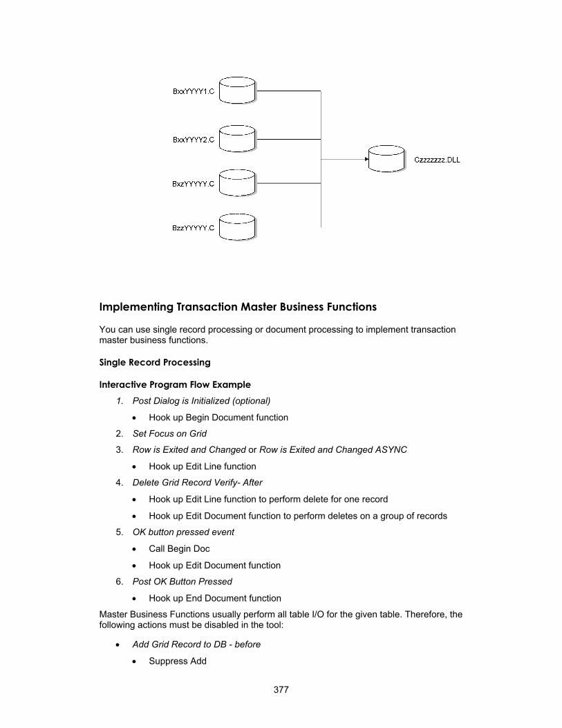
Implementing Transaction Master Business Functions
You can use single record processing or document processing to implement transaction master business functions.
Single Record Processing
Interactive Program Flow Example 1. Post Dialog is Initialized (optional)
• Hook up Begin Document function
2. Set Focus on Grid
3. Row is Exited and Changed or Row is Exited and Changed ASYNC
• Hook up Edit Line function
4. Delete Grid Record Verify- After
• Hook up Edit Line function to perform delete for one record
• Hook up Edit Document function to perform deletes on a group of records
5. OK button pressed event
• Call Begin Doc
• Hook up Edit Document function
6. Post OK Button Pressed
• Hook up End Document function
Master Business Functions usually perform all table I/O for the given table. Therefore, the following actions must be disabled in the tool:
• Add Grid Record to DB - before
• Suppress Add
377

• Update Grid Record to DB - before
• Suppress Update
• Delete Grid Record to DB - before
• Suppress Delete
Batch Program Flow Example 1. Do Section of Report Header
• Hook up Begin Document function
2. Do Section of the Group Section
• Hook up Edit Line function
3. Do Section of a Conditional Section (optional)
• Hook up Edit Document function
4. Do Section of Report Footer
• Hook up End Document function
Document Processing
1. Dialog is Initialized
• Hook up Edit Document Edit Object module
5. Before Add/Delete from Database event
J.D. Edwards provides master business functions (MBFs) to allow calling programs to process certain predefined transactions. An MBF encapsulates the required logic, enforces data integrity, and insulates the calling programs from the database structures.
Program Flow Example
• Hook up Open Batch Edit Object module
2. Grid is entered - Finished entering in header
• Hook up Begin Document Edit Object module
3. Row is exited
• Hook up Edit Line Edit Object module
4. OK button is pressed
• Suppress Add/Delete
• Hook up End Document Edit Object module
6. Cancel button is pressed
• Hook up Close Batch Edit Object module
Master File Master Business Functions
MBFs are similar to the functional servers in WorldSoftware. You can use MBFs for the following reasons:
378

• To create reusable, application-specific code
• To reduce duplicated code
• To ensure that hookup is consistent
• To support interoperability models
• To allow processing to be distributed through OCM
• To design event-driven architecture
MBFs are typically used for multiline business transactions, such as Journal Entries or Purchase Orders. However, certain master files also require MBF support due to their complexity, importance, or maintenance requirements from external parties. The requirements for maintaining master files are different from those for multiline business transactions.
Address Book and Item Master require MBF support.
Generally, master file MBFs are much simpler than multi-line business transaction MBFs. Transaction MBFs are specific to a program, while master file MBFs access a table multiple times.
For interoperability, master file MBFs can be used instead of table I/O. This allows you to perform updates to related tables using the business function instead of table event rules. Multiple records are not used. Instead, all edits and actions are performed with one call.
In their basic form, master file MBFs have the following characteristics:
Single call Generally, you can make one call to an MBF to edit, add, update, or delete a master file record. An edit-only option is also available.
Single data structure
The fields required to make the request and provide all the necessary values are in one data structure. The data fields should correspond directly with columns in the associated master file.
No cache Because each master file record is independent of the others, caching is unnecessary. The information provided with each call and the current condition of the database provide all of the information that the MBF needs to perform the requested function.
Normal error handling
As with other MBFs, master file MBFs must be capable of executing in both an interactive and batch environment. Therefore, the calling program must determine the delivery mechanism of the errors.
Inquiry feature To allow external systems to be totally insulated from the J.D. Edwards database, an inquiry option is included. This allows an external system to use the same interface to access descriptive information about a master file key as it uses to maintain it.
Affect on applications
For OneWorld applications, the effect of implementing a master file MBF should be minimal. Consider and follow several standards before implementing a master file MBF.
Master file applications use the OneWorld tool to process all I/O for the Find/Browse forms. This allows you to use all of the search capabilities of OneWorld.
You should design all master file applications so that all Fix/Inspect forms are independent of each other. Each Fix/Inspect form can use the OneWorld tool to fetch the record, and all edits and updates occur using the master file MBF. This independent design has the following two major benefits:
379
• It organizes the application in a manner that simplifies edits that involve dependent fields across multiple forms.
• It allows consistent implementation of modeless processing for all Master File applications and all forms within these applications.
For example, if the customer master file exceeded the data structure limitation, you would use the following two MBFs to process the file:
Certain circumstances might justify deviation from this simple model. These circumstances are:
• Extremely large file formats
When the number of columns in the master file plus the required control fields in the call data structure exceed technical limitations for data structures, the MBF can be split. J.D. Edwards recommends that you split the MBF into one MBF that handles base data and performs all adds and deletes, and one or more others that allow the calling program to update additional data when the base data has been established. In this case, it is usually logical to split it, regardless of the technical limitation.
• F0301ProcessMasterData
• F0301ProcessBillingData
In this example, the F0301ProcessMasterData function processes the base data, and the F0301ProcessBillingData updates additional data.
• Subordinate detail files
Information can exist in addition to the primary master file that has been normalized to allow for a one-to-many relationship. Designing the Master File MBF strictly on the basis of how the database is designed translates into three calls. Including at least one occurrence of a detail relationship in the data structure of a Master File MBF is valid. This inclusion allows users to establish reasonably complete master file information using a simple interface to meet simple needs.
Street addresses and phone numbers within Address Book are a good example. Customers expect that they can create an address book record by calling a simple address book API with basic identifying information, the street address, and a phone number.
Information Structure
Standard Parameters for Single Record Master Business Functions
Name Alias I/O Required/Optional Description
Action Code ACTN I Required A = Add
I = Inquiry
C = Change
D = Delete
S = Same as except (The record is the same except for what the user changes.)
Update Master File EV01 I Optional 0 = No update edit only (Default)
1 = Update performed
380

Process Edits EV02 I Optional 1 = All Edits (Default)
2 = Partial Edits (No Data Dictionary)
Suppress Error Messages
SUPPS I Optional 1 = Error Messages are Suppressed
0 = Process Errors Normally (Default)
Error Message ID DTAI O Optional Returns error code
Version VERS I Future Default to XJDE0001
Application Specific Control Parameters (Example: Address Book)
Name Alias I/O Required/ Optional
Description
Address Book Number
AN8 I/O Optional For additions, AN8 is optional. For all other Action codes, this parameter is required.
Same as except AN8 I Optional Required for S = Action Code The record is the same except for what the user changes.
Application Parameters (Example: Address Book)
Name Alias I/O Required/Optional
Alpha Name ALPH I/O Required
Long Address Number ALKY I/O Optional
Search Type AT1 I Required
Mailing Name MLMN I Required
Address Line 1 ADD1 I Optional
City CTY1 I Optional
State ADDS I Optional
Postal Code ADDZ I Optional
Naming Convention
• The functional server source is named Nxxxxxxx for named event rule business functions or Bxxxxxxx for C business functions, which is the same naming convention as that for any other business function. Within this source is an external business function for each of the modules. The data structure name for each module is DxxxxxxA, B, C and so on (for example, N03000052 - D03000052A F0301ProcessMasterData, D03000052B F0301ProcessBillingData).
• The individual business function is named file nameProcessMasterData (for example, F0301ProcessMasterData). If additional master file functions are needed due to data structure limitations, then the function name is named file nameProcessxxxxxxxxx, where xxxxxxxxx represents a descriptive name for the type of data being processed (for example, F0301ProcessBillingData).
381
• The functional use code of 192 in the Object Librarian is used to designate business functions as a functional server.
Performance Impact
Performance issues might occur regardless of how you handle large-format tables. Two options for improving performance are:
• Group data in logical groups to allow data structures to be smaller and easier for the user to implement. However, this configuration forces the user to make multiple calls to add or update an entire record in a table.
• Use a data structure that allows 300 fields. This is also cumbersome to implement, and the user can choose not to apply all of the fields.
Through different interfaces, the user can add additional data later. Most processes dictate that part of the data be added immediately, while other related data can be added later. For example, the user might define a customer master record, but wait until a later date to define the customer's billing instructions. Therefore, J.D. Edwards recommends that you choose the first option of splitting MBFs into one MBF that handles base data and one MBF that handles additional data.
Business Function Documentation
Business function documentation explains what individual business functions do and how they should be used. The documentation for a business function should include information such as the following:
• Purpose
• Parameters (the data structure used)
• Explanation of each individual parameter that indicates input and output required, and explanation of return values
• Related tables (the table accessed)
• Related business functions (business functions called from within the functions itself)
• Special handling instructions
You use Business Function Design and Data Structure Design to document your business functions.
Creating Business Function Documentation
You can create business function documentation at several levels, including:
Business Function Notes Shows you the documentation for the specific business function that you are using.
Data Structure Notes Displays notes about the data structure for the business function.
Parameter Notes Displays notes about the actual parameters in the data structure.
382

► To create business function documentation
1. On Object Management Workbench, choose the business function that you want to document, and then click the Design button in the center column.
2. On Business Functions Design, click the Attachments tab.
3. Right-click in the icon bar on the left side of the form, and then select Templates.
4. On Work With Media Object Templates, click Find.
5. Select the template that you want to use.
J.D. Edwards uses the Business Function template as a standard.
383

6. Type the appropriate information under each template heading.
Business Function Documentation Template The Business Function documentation template contains the following sections:
Purpose This section contains a brief summary of what the function does.
Setup Notes and Prerequisites This section includes any special notes to assist in using the function, including prerequisite functions, special values that need to be initialized, and events that are recommended to run the function. It also indicates whether memory must be cleared separately after the function is used.
Special Logic This section contains additional details about the business function logic. You typically use it only for complex functions that require more explanation than the purpose summary.
Technical Specification This section contains the technical specification of the function, written in scripted English. It can be a direct copy from an existing word processing document.
Creating Data Structure Documentation Use the following process to create data structure documentation.
384
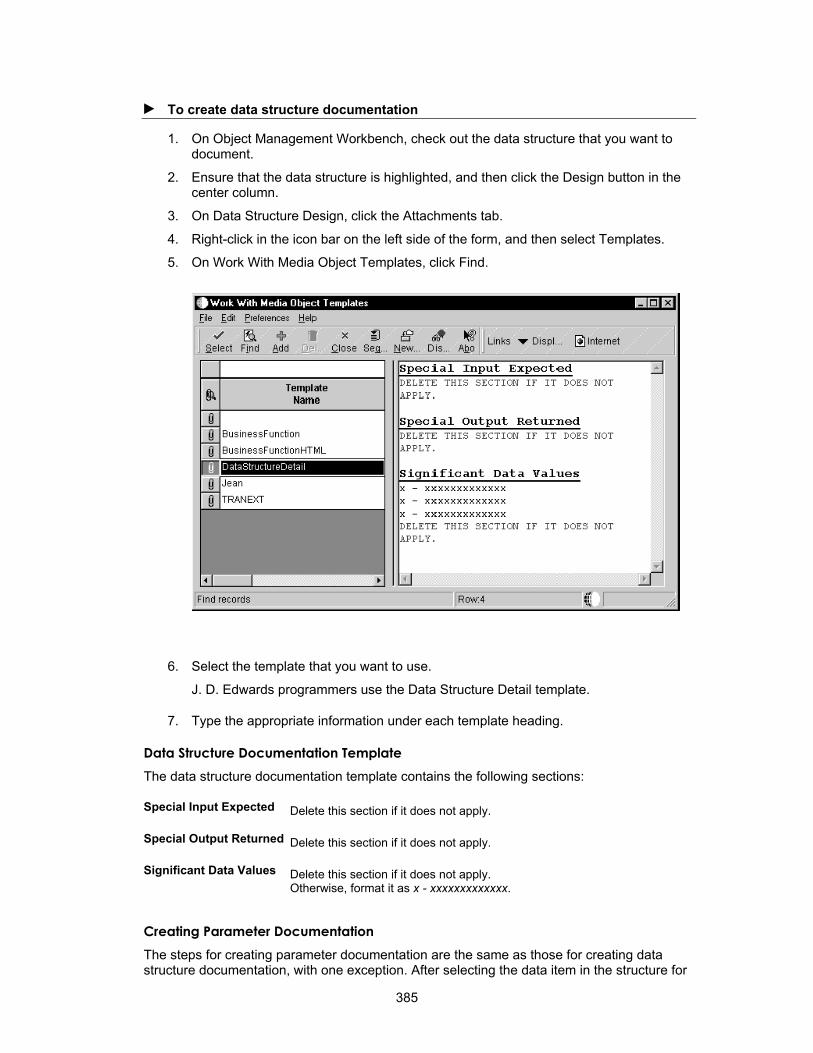
► To create data structure documentation
1. On Object Management Workbench, check out the data structure that you want to document.
2. Ensure that the data structure is highlighted, and then click the Design button in the center column.
3. On Data Structure Design, click the Attachments tab.
4. Right-click in the icon bar on the left side of the form, and then select Templates.
5. On Work With Media Object Templates, click Find.
6. Select the template that you want to use.
J. D. Edwards programmers use the Data Structure Detail template.
7. Type the appropriate information under each template heading.
Data Structure Documentation Template The data structure documentation template contains the following sections:
Special Input Expected Delete this section if it does not apply.
Special Output Returned Delete this section if it does not apply.
Significant Data Values Delete this section if it does not apply. Otherwise, format it as x - xxxxxxxxxxxxx.
Creating Parameter Documentation The steps for creating parameter documentation are the same as those for creating data structure documentation, with one exception. After selecting the data item in the structure for
385
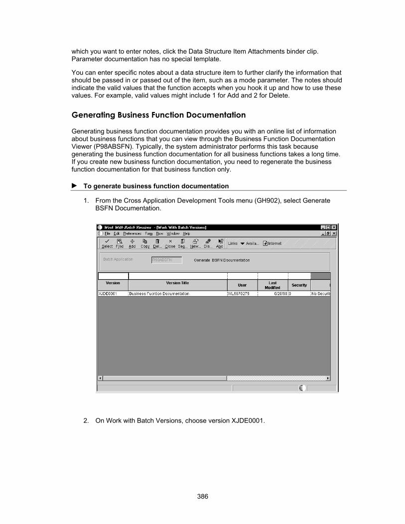
which you want to enter notes, click the Data Structure Item Attachments binder clip. Parameter documentation has no special template.
You can enter specific notes about a data structure item to further clarify the information that should be passed in or passed out of the item, such as a mode parameter. The notes should indicate the valid values that the function accepts when you hook it up and how to use these values. For example, valid values might include 1 for Add and 2 for Delete.
Generating Business Function Documentation
Generating business function documentation provides you with an online list of information about business functions that you can view through the Business Function Documentation Viewer (P98ABSFN). Typically, the system administrator performs this task because generating the business function documentation for all business functions takes a long time. If you create new business function documentation, you need to regenerate the business function documentation for that business function only.
► To generate business function documentation
1. From the Cross Application Development Tools menu (GH902), select Generate BSFN Documentation.
2. On Work with Batch Versions, choose version XJDE0001.
386
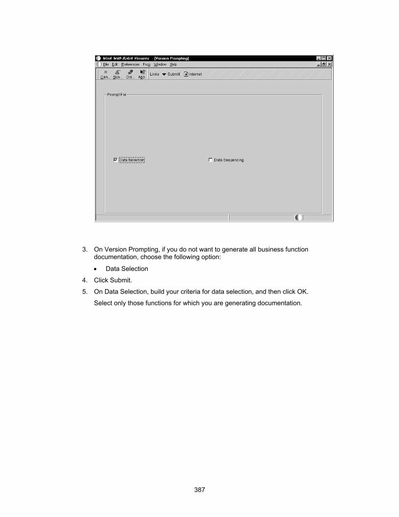
3. On Version Prompting, if you do not want to generate all business function documentation, choose the following option:
• Data Selection
4. Click Submit.
5. On Data Selection, build your criteria for data selection, and then click OK.
Select only those functions for which you are generating documentation.
387
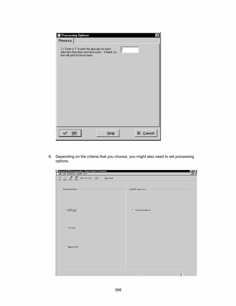
6. Depending on the criteria that you choose, you might also need to set processing options.
388

7. On Report Output Destination, if you are running your report locally, choose one of the following output destinations:
• On Screen
• To Printer
The system creates a hypertext markup language (HTML) link for each business function for which you generated documentation. It also creates an Index HTML file. These HTML files appear in your output queue directory. Output is in the following format:
Function Name
Function Description from
Parent DLL:
Location:
Language:
Purpose
Special Handling
Data Structure
Parameter Name dataitem data type req/ opt
Data Selection Tips You can use data selection to choose the business functions for which you wish to generate documentation. Generate BSFN Documentation (R98ABSFN) uses your data selection criteria to filter the business function documentation. The report might take a long time to run when you generate documentation for all business functions. You can use data selection to generate documentation for one business function, all business functions, or any combination of business functions.
For example, if you want to generate documentation for a single business function, you can use the data item BC Object Name (F9860).
If you want to generate documentation for all of the business functions for a specific product code, such as Payroll, you use the data item BC Product Code (F9860).
389

You can also use the right operand on the Data Selection form to choose ranges or lists of values to further refine your filter.
You can filter using any value that is associated with a business function. For example, you can use BC Date - Updated (F9860) if you have already produced the documentation for a previous release of OneWorld and, after an upgrade or update of OneWorld®, you want to create documentation for only new or modified business functions.
You use BC Function Type (F9860) to choose Master business function documentation.
You use BC Location Business Function (F9860) to produce documentation for client-run business functions.
You use BC Object Type (F9860) to generate documentation for NERs only.
You can use many other informational fields to choose the business functions for which you want to generate documentation.
Viewing Business Function Documentation
Viewing Documentation from Business Function Search When you make a connection to a business function in event rules, the Business Function Search form appears.
390

You can then select the function that you want to call. From the row menu, choose Data Structure Notes or Attachments to view the documentation for the business function.
Viewing Documentation from Business Function - Values to Pass
391

You can click one of the following buttons on Business Function - Values to Pass to view documentation for a single business function.
• Business Function Notes
• Structure Notes
• Parameter Notes
BSFN Notes Displays the notes for the business function.
Structure Notes Displays the notes for the whole data structure.
Parameter Notes Displays the notes for a particular parameter.
Refer to Business Function Event Rules for more information about accessing this form.
Viewing Documentation from Business Function Documentation Viewer From the Cross Application Development Tools menu (GH902), choose Business Function Documentation Viewer.
You can use Business Function Documentation Viewer to view documentation for all business functions or selected business functions. After you have generated your report, use the Business Function Documentation Viewer (P98ABSFN) to display your information. J.D. Edwards suggests that you use this method to view business function documentation.
The Business Function Documentation form contains the HTML index that you generated. You can either view the entire index or select just the functions for a specific letter in the alphabet by clicking on that letter in the index. Double-click a business function to view documentation that is specific to that function.
392

The media object loads the HTML index of the business functions, based on a media object queue. In the media object queue table, a queue named Business Function Doc must be set up.
This queue must point to the directory in which the business function HTMLs are located. The system administrator usually generates the documentation for all business functions. Because the generation process places the documentation files in the local directory, the administrator must then copy the files to a central directory on the deployment server. The files must be copied to the media object queue for media object business function notes. If you are using the standalone version of OneWorld, this path is usually the output directory from the Network Queue Settings section of your jde.ini file. If this entry is not in your jde.ini file, it is in the print queue directory in your OneWorld directory.
Understanding Business Function Processing Failovers
In some instances in which a business function fails to process correctly, OneWorld can attempt to recover and reprocess the transaction. The system recognizes two principle failure states: process failure and system failure.
A process failure occurs when a jdenet_k process aborts abnormally. For a process failure, OneWorld server processing launches a new jdenet_k process and continues processing.
A system failure occurs when all OneWorld server processing fails, the machine itself is down, or the client cannot reach the server because of network problems. For a system failure, business function processing must be rerouted either to a secondary server or to the local client. The system uses the following process to attempt to recover from this state:
When the call to the server fails, the system attempts to reconnect to the server.
393

• If reconnect succeeds and no cache exists, the system reruns the business function on the server. If a cache does exist, the system forces the user out of the application.
• If reconnect fails and no cache exists, the system switches to a secondary server or to the local client. If a cache does exist, the system forces the user out of the application.
After one module switches, all subsequent modules switch to the new location.
394
Caching
Caching is storing a local copy of frequently accessed content of remote objects. You can use caching to improve performance. OneWorld uses the following two types of caching:
• OneWorld automatically caches certain tables, such as constants tables, when it reads them from the database at startup. OneWorld caches these tables to a user's workstation or to a server for faster data access.
• OneWorld applications are enabled to use cache. JDECACHE APIs allow the server or workstation memory to be used as temporary storage.
Understanding JDECACHE
JDECACHE is a component of JDEKRNL that can hold any type of indexed data that your application needs to store in memory, regardless of the platform on which the application is running on. This means that a whole table can be read from a database and stored in memory. There is no limitation on the type of data, size of data, or number of data caches that an application can have, other than the limitations of the computer on which it is running. Both fixed-length and variable-length records are supported. To use JDECACHE on any supported platform, you need to know only a simple set of API calls.
Data handled by JDECACHE is in RAM. Therefore, ensure that you really need to use JDECACHE. If you use JDECACHE, design your records and indices carefully. Minimize the number of records that you store in JDECACHE because OneWorld and various other applications need this memory, as well.
JDECACHE supports multiple cursors, multiple indexes, and partial keys processing. JDECACHE gives you flexibility in terms of positioning within the cache for data manipulation. This improves performance by reducing searching within the cache.
When to Use JDECACHE
The following example describes when an application might use the JDECACHE APIs.
You use workfiles when an application must store records that a user enters in a detail area until OK processing on the Button Clicked event. On OK processing, all records must be updated to the database simultaneously. This is similar to transaction processing. For example, in the detail area of purchase order detail, if a user enters 30 lines of information and then decides to cancel the transaction, all records in the work file are deleted and nothing is written to the database. As the user exits each detail row, editing takes place for each field, and then that record is written to the work file.
If you implement this situation without using work files, irreversible updates to database tables occur when the user exits each row. Using work files allows you to limit updates to tables so that they only occur on OK button processing, and they are included in a transaction boundary. The work file defines a data boundary for the grid for processing purposes. This is useful when multiple applications or processes (such as business functions) must access the data in the work file for updates and calculations.
Although using work files for the example above will function correctly, using cache will probably increase performance. You can use JDECACHE to store in memory the records that the user enters in one purchase order. The number of records that you store depends on the cache buffer size for each record, the local memory size, the location in which the business function that you use runs (server or workstation), and so on. Typically, you should not store
395

more than 1000 records. For example, do not cache your entire Address Book table in memory.
Performance Considerations
The following are some guidelines for getting the best performance out of JDECACHE:
• If you use JDECACHE, cache as few records as possible.
• The fewer columns (segments) that you use, the faster your searches, inserts, and deletes occur. In some cases, the system might have to compare each column before it determines whether to go further in the cache.
• The fewer records in your cache, the faster all operations proceed.
The JDECACHE API Set
You use a set of public APIs to interact with JDECACHE. You must understand how the JDECACHE APIs are organized to implement them effectively.
JDECACHE Management APIs
You can manage cache using the JDECACHE management APIs for the following:
• Setting up the cache
• Clearing the cache
• Terminating the cache
Use the jdeCacheGetNumRecords and jdeCacheGetNumCursors APIs to retrieve cache statistics. They are only passed the HCACHE handle. All other JDECACHE management APIs should always be passed the following handles:
• HUSER
• HCACHE
These two handles are essential for cache identification and cache management.
The set of JDECACHE management APIs consist of the following APIs:
• jdeCacheInit
• jdeCacheInitMultipleIndex
• jdeCacheInitUser
• jdeCacheInitMultipleIndexUser
• jdeCacheGetNumRecords
• jdeCacheGetNumCursors
• jdeCacheClear
• jdeCacheTerminate
• jdeCacheTerminateAll
jdeCacheInit/jdeCacheInitMultipleIndex initializes the cache uniquely per user. Therefore, if a user logs in to OneWorld and then runs two sessions of the same application simultaneously, the two application sessions will share the same cache. Consequently, if the first application deletes a record from the cache, the second application cannot access the record.
396

Conversely, if two users log in to OneWorld and then run the same application simultaneously, the two application sessions have different caches. Consequently, if the first application deletes a record from its cache, the second application will still be able to access the record in its own cache.
jdeCacheInitUser/jdeCacheInitMultipleIndexUser initializes the cache uniquely per application. Therefore, if a user logs in to OneWorld and then runs two sessions of the same application simultaneously, the two application sessions will have different caches. Consequently, if the first application deletes a record from its cache, the second application can still access the record in its own cache.
JDECACHE Manipulation APIs
You can use the JDECACHE manipulation APIs for retrieving and manipulating the data in the cache. Each API implements a cursor that acts as pointer to a record that is currently being manipulated. This cursor is essential for navigation within the cache. JDECACHE manipulation APIs should be passed handles of the following types:
HCACHE Identifies the cache that is being worked
HJDECURSOR Identifies the position in the cache that is being worked
The set of JDECACHE manipulation APIs consists of the following APIs:
• jdeCacheOpenCursor
• jdeCacheResetCursor
• jdeCacheAdd
• jdeCacheFetch
• jdeCacheFetchPosition
• jdeCacheUpdate
• jdeCacheDelete
• jdeCacheDeleteAll
• jdeCacheCloseCursor
• jdeCacheFetchPositionByRef
• jdeCacheSetIndex
• jdeCacheGetIndex
Working with JDECACHE
The JDB environment implicitly creates, manages, and destroys the JDECACHE environment. Each cache that you use within the JDECACHE environment is associated with a JDB user. Therefore, you must call JDB_InitBhvr API before you call any of the JDECACHE APIs.
Before you can use JDECACHE, you must initialize a cache. You must define an index before you initialize a cache. The index tells the cache which fields in a record to use to uniquely identify a cache record. You must create a separate cache for each group of data that an index references.
397

Calling JDECACHE APIs
JDECHACHE APIs must be called in a certain order. The following steps list the order in which the JDECACHE-related APIs must be called, except for step 6, when the actual JDECACHE APIs may be called in any order:
1. JDB_InitBhvr
2. Create index or indices
3. jdeCacheInit or jdeCacheInitMultipleIndex
4. jdeCacheAdd
5. jdeCacheOpenCursor
6. JDECACHE Operations
The rest of JDECACHE operations can occur in any order:
jdeCacheFetch
jdeCacheOpenCursor (the second cursor)
jdeCacheFetchPosition
jdeCacheUpdate
jdeCacheDelete
jdeCacheDeleteAll
jdeCacheResetCursor
jdeCacheCloseCursor (if the second cursor is opened)
7. jdeCacheCloseCursor
8. jdeCacheTerminate
9. JDB_FreeBhvr
Setting Up Indices
To store or retrieve any data in JDECACHE, you must set up one and only one index that consists of at least one column. The index is limited to a maximum of 25 columns, which are called segments, in the index structure. Use the data type that is provided to you to tell the cache manager what your index looks like. You must provide the number of columns (segments) in the index and the offset and size of each column in your data structure. To maximize performance, minimize the number of segments.
The following is the definition of the structure that holds index information:
#define JDECM_MAX_UM_SEGMENTS 25
struct _JDECMKeySegment
{
short int nOffset; /* Offset from beginning of structure in bytes */
short int nSize; /* Size of data item in bytes */
398
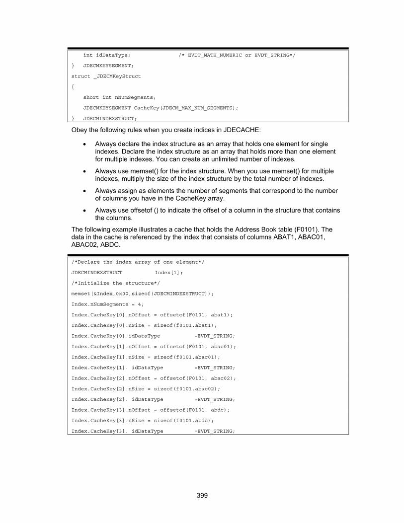
int idDataType; /* EVDT_MATH_NUMERIC or EVDT_STRING*/
} JDECMKEYSEGMENT;
struct _JDECMKeyStruct
{
short int nNumSegments;
JDECMKEYSEGMENT CacheKey[JDECM_MAX_NUM_SEGMENTS];
} JDECMINDEXSTRUCT;
Obey the following rules when you create indices in JDECACHE:
• Always declare the index structure as an array that holds one element for single indexes. Declare the index structure as an array that holds more than one element for multiple indexes. You can create an unlimited number of indexes.
• Always use memset() for the index structure. When you use memset() for multiple indexes, multiply the size of the index structure by the total number of indexes.
• Always assign as elements the number of segments that correspond to the number of columns you have in the CacheKey array.
• Always use offsetof () to indicate the offset of a column in the structure that contains the columns.
The following example illustrates a cache that holds the Address Book table (F0101). The data in the cache is referenced by the index that consists of columns ABAT1, ABAC01, ABAC02, ABDC.
/*Declare the index array of one element*/
JDECMINDEXSTRUCT Index[1];
/*Initialize the structure*/
memset(&Index,0x00,sizeof(JDECMINDEXSTRUCT));
Index.nNumSegments = 4;
Index.CacheKey[0].nOffset = offsetof(F0101, abat1);
Index.CacheKey[0].nSize = sizeof(f0101.abat1);
Index.CacheKey[0].idDataType =EVDT_STRING;
Index.CacheKey[1].nOffset = offsetof(F0101, abac01);
Index.CacheKey[1].nSize = sizeof(f0101.abac01);
Index.CacheKey[1]. idDataType =EVDT_STRING;
Index.CacheKey[2].nOffset = offsetof(F0101, abac02);
Index.CacheKey[2].nSize = sizeof(f0101.abac02);
Index.CacheKey[2]. idDataType =EVDT_STRING;
Index.CacheKey[3].nOffset = offsetof(F0101, abdc);
Index.CacheKey[3].nSize = sizeof(f0101.abdc);
Index.CacheKey[3]. idDataType =EVDT_STRING;
399

The flag idDataType indicates the data type of the particular key. The following illustration uses ABAN8, which is a MATH_NUMERIC:
Index.nNumSegments = 1;
Index.CacheKey[0].nOffset = offsetof(F0101, aban8);
Index.CacheKey[0].nSize = sizeof(f0101. aban8);
Index.CacheKey[0]. idDataType = EVDT_MATH_NUMERIC;
The following example illustrates a cache with multiple indices.
/*Declare the index array of 2 elements*/
JDECMSTRUCT Index[2];
int numIndexes=2;
/*Initialize the structure*/
memset(&Index,0x00,sizeof(JDECMSTRUCT)* numIndexes);
Index[0].nkeyID = 1;
Index[0].nNumSegments = 1;
Index[0].CacheKey[0].nOffset=offsetof(F0101,abat1);
Index[0].CacheKey[0].nSize=sizeof(f0110.abat1);
Index[0].CacheKey[0].idDataType=EVDT_STRING;
Index[1].nkeyID = 2;
Index[1].nNumSegments = 2;
Index[1].CacheKey[0].nOffset=offsetof(F0101,abac02);
Index[1].CacheKey[0].nSize=sizeof(f0110. abac02);
Index[1].CacheKey[0].idDataType=EVDT_STRING;
Index[1].nNumSegments = 1;
Index[1].CacheKey[1].nOffset=offsetof(F0101,abat1);
Index[1].CacheKey[1].nSize=sizeof(f0110.abat1);
Index[1].CacheKey[1].idDataType=EVDT_STRING;
Initializing the Cache
After you set up the index or indices, call jdeCacheInit or jdeCacheInitMultipleIndex to initialize (create) the cache.
Pass a unique cache name so that JDECACHE can identify the cache. Pass the index to this API so that the JDECACHE knows how to reference the data that will be stored in the cache. Because each cache must be associated with a user, you must also pass the user handle obtained from the call to JDB_InitUser. This API returns an HCACHE handle to the cache that JDECACHE creates. This handle appears in every subsequent JDECACHE API to identify the cache.
The keys in the index must always be the same for every jdeCacheInit and jdeCacheInitMultipleIndex call for that cache until it is terminated. The keys in the index must correspond in number, order, and type for that index each time that it is used.
400

After the cache has been initialized successfully, JDECACHE operations can take place using the JDECACHE APIs. The cache handle obtained from jdeCacheInit must be passed for every JDECACHE operation.
JDECACHE makes an internal Index Definition Structure that accesses the cache when it is populated. The following example illustrates what happens when an index is defined and passed to jdeCacheInit.
Example: Index Definition Structure You decide that the records that the cache stores each consist of the following structure:
int nlnt1
char cLetter1
char cLetter2
char cLetter3
char szArray(5)
You decide that each of the records in the cache will be indexed uniquely by the values contained in the following:
• nInt1
• cLetter1
• cLetter3
You pass that information to jdeCacheInit, and JDECACHE creates the following Index Definition Structure for internal use. The Index Definition Structure is for STRUCT letters.
401
Using an Index to Access the Cache
When you use an index to access the cache, the keys in the index that are sent to the API must correspond to the keys of the index used in the call to jdeCacheInit for that cache in number, order, offset positions, and type. Therefore, if a field that was used in the index passed to jdeCacheInit offsets position 99, it must also offset position 99 in the index structure that passed to JDECACHE access API.
You should use the same index structure that was used for the call to jdeCacheInit whenever you call an API that requires an index structure.
The following example illustrates why the index offsets must be specified for the jdeCacheInit and how they are used when a record is to be retrieved from the cache. It shows how the passed key is used in conjunction with the JDECACHE internal index definition structure to access cache records.
Example: JDECACHE Internal Index Definition Structure The user is looking for a record that matches the following index key values:
• 1
• c
• i
JDECACHE accesses the values that you pass in the structure at the byte offsets that were defined in the call to jdeCacheInit.
JDECACHE compares the values 1, c, and i that it retrieves from the passed structure to the corresponding values in each of the cache records at the corresponding byte offset. The cache records are stored as the structures that were inserted into the cache by jdeCacheAdd, which is the same structure as the one you pass first. The structure that matches the passed key is the second structure to which HCUR1 points.
You should never create a smaller structure that contains just the key in order to access the cache. Unlike most indexing systems, JDECACHE does not store a cache record's index separately from the actual cache record. This is because JDECACHE deals with memory-resident data and is designed to be as memory-conservative as possible. Therefore, JDECACHE does not waste memory by storing an extra structure for the sole purpose of indexing. Instead, a JDECACHE record has a dual purpose of index storage and data storage. This means that, when you retrieve a record from JDECACHE using a key, the key should be contained in a structure that is of the same type as the structure that is used to store the record in the cache.
Do not use any key structure to access the cache other than the one for which offsets that were defined in the index passed to jdeCacheInit. The structure that contains the keys when accessing a cache should be of the same structure that is used to store the cache records.
The following diagram shows what happens when any structure, other than the one that you used in the index definition, is used to insert into the cache.
402

If jdeCacheInit is called twice with the same cache name and the same user handle without an intermediate call to jdeCacheTerminate, the cache that was initialized using the first jdeCacheInit will be retained. Always call jdeCacheInit with the same index each time you call it with the same cache name. If you call jdeCacheInit for the same cache with a different index, none of the JDECACHE APIs will work.
The key for searches must always use the same structure type that stores cache records.
Using the jdeCacheInit/jdeCacheTerminate Rule
For every jdeCacheInit or jdeCacheInitMultipleIndex, a corresponding jdeCacheTerminate must exist, except if the same cache is used across business functions or forms. In this case,
403

all unterminated jdeCacheInit or jdeCacheInitMultipleIndex calls must be terminated with a jdeCacheTerminateAll.
A jdeCacheTerminate call terminates the most recent corresponding jdeCacheInit. This means that the same cache can be used in nested business functions. In each function, perform a jdeCacheInit that passes the cache name. Before exiting that function, call jdeCacheTerminate. This does not destroy the cache. Instead, it destroys the association between the cache and the passed HCACHE handle. The cache is completely destroyed from memory only when the number of jdeCacheTerminate calls matches the number of jdeCacheInit calls. In contrast, one call to jdeCacheTerminateAll destroys the cache from memory regardless of the number of jdeCacheInit or jdeCacheInitMultipleIndex calls or jdeCacheTerminate calls.
Using the Same Cache in Multiple Business Functions or Forms
If the same cache is required for two or more business functions or forms, call jdeCacheInit in the first business function or form, and add data to it. After exiting that business function or form, do not call jdeCacheTerminate because this removes your cache from memory. Instead, in the subsequent business functions or forms, call jdeCacheInit again with exactly the same index and cache name as in the initial call to jdeCacheInit. Because the cache was not terminated the first time, JDECACHE looks for a cache with exactly the same name and assigns that to you. Because the cache already has records in it, you do not need to refresh it. You can proceed with normal cache operations on that cache.
If a cache is initialized multiple times across business functions or forms, use jdeCacheTerminateAll to terminate all instances of the cache that were initialized. The name of the cache that corresponds to the HCACHE passed to this API will be used to determine the cache to destroy. Use this API when you do not want to call jdeCacheTerminate for the number of times that jdeCacheInit was called. If you move from one form or business function to another when you initialize the same cache across business functions or forms, you will lose your HCACHE because it is a local variable. To share the same cache across business functions or forms, do not call jdeCacheTerminate when you exit a form or business function if you intend to use the same cache in another form or business function.
JDECACHE Cursors
JDECACHE Cursors (JDECACHE Cursor Manager) is a component of JDECACHE that implements a JDECACHE Cursor for record retrieval and update. A JDECACHE Cursor is a pointer to a record in a user's cache. The record after the record in which the cursor is currently pointing is the next record that will be retrieved from the cache upon calling a cache fetch API. Thus, a cursor is very effective for positioning yourself in the cache for data access.
Opening a JDECACHE Cursor
Manipulating the JDECACHE data is cursor-dependent. Before the JDECACHE Data Manipulation APIs will work, a cursor must be opened. A cursor must be opened in order to obtain a cursor handle of the type HJDECURSOR, which must, in turn, be passed to all of the JDECACHE data manipulation APIs (with the exception of the jdeCacheAdd API). To open the cursor, make a call to the jdeCacheOpenCursor API. A call to this API also makes possible the calls to all the data manipulation APIs, except for jdeCacheAdd). If you do not open the cursor, these APIs will not work. With this call, the cursor opens a JDECACHE Dataset within which it will work. This API opens the dataset, but does not fetch any data.
404

This means that the cache must be initialized by a call to jdeCacheInit and populated by a call to jdeCacheAdd before a cursor can be opened.
You can obtain multiple cursors to a cache by calling jdeCacheOpenCursor and passing different HJDECURSOR handles. In a multiple cursor environment, all the cursors are independent of each other. See JDECACHE Multiple Cursor Support for more information.
When you are finished working with the cursor, you must deactivate it or close it by calling the jdeCacheCloseCursor API, and passing an HJDECURSOR handle that corresponds to the HJDECURSOR handle that was passed to the jdeCacheOpenCursor. When a cursor is closed, it cannot be used again until it is opened by a call to jdeCacheOpenCursor.
HJDECURSOR
HJDECURSOR is the data type for the cursor handle. It must be passed to every API for JDECACHE Data Manipulation except jdeCacheAdd.
JDECACHE Dataset
The JDECACHE dataset includes all of the records from the current position of the cursor to the end of the set of sequenced records. Thus, if a cursor is in the middle of the dataset, none of the records in the cache prior to the current position of the cursor is considered part of the dataset. The JDECACHE Dataset consists of the cache records sequenced in ascending order of the given index keys. This, in fact, means that the order in which the records have been placed in JDECACHE is not necessarily the order in which JDECACHE Cursors retrieves them. JDECACHE Cursors retrieves records in a sequential ascending order of the index keys. A forward movement by the cursor reduces the size of the dataset during sequential retrievals. When the cursor advances past the last record in the dataset, a failure is returned.
405
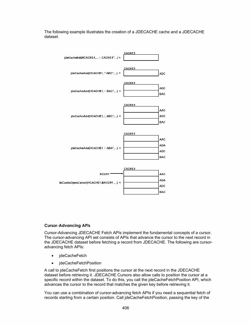
The following example illustrates the creation of a JDECACHE cache and a JDECACHE dataset.
Cursor-Advancing APIs Cursor-Advancing JDECACHE Fetch APIs implement the fundamental concepts of a cursor. The cursor-advancing API set consists of APIs that advance the cursor to the next record in the JDECACHE dataset before fetching a record from JDECACHE. The following are cursor-advancing fetch APIs:
• jdeCacheFetch
• jdeCacheFetchPosition
A call to jdeCacheFetch first positions the cursor at the next record in the JDECACHE dataset before retrieving it. JDECACHE Cursors also allow calls to position the cursor at a specific record within the dataset. To do this, you call the jdeCacheFetchPosition API, which advances the cursor to the record that matches the given key before retrieving it.
You can use a combination of cursor-advancing fetch APIs if you need a sequential fetch of records starting from a certain position. Call jdeCacheFetchPosition, passing the key of the
406

record from which you want to start retrieving. This advances the cursor to the desired location in the dataset and retrieves the record. All subsequent calls to jdeCacheFetch will fetch records starting from the current cursor position in the data set until the end of the dataset, or until the program stops for another reason.
Non-Cursor-Advancing APIs Non-cursor-advancing JDECACHE Cursor APIs do not advance the cursor before retrieving a record but, instead, keep the cursor pointing to the retrieved record. The following are non-cursor-advancing fetch APIs:
• jdeCacheUpdate
• jdeCacheDelete
Updating Records
If you want to update a specific record with a key that you know, call jdeCacheFetchPosition, passing the known key, to position the cursor at the location of the record that matches the key. Because the cursor is already pointing to the desired location, call jdeCacheUpdate, passing the same HJDECURSOR that you used in the call to jdeCacheFetchPosition.
If the index key changes, cache resorts the records again, and the cursor points to the updated location. However, when you call jdeCacheFetch, the system retrieves the next record in the updated set. Consequently, the system might not retrieve the correct record because changing the index key caused the order of the records to change.
To update a sequential number of records, make a call to jdeCacheFetchPosition to get to the beginning of the sequence, if necessary. Then call jdeCacheUpdate, passing the same HJDECURSOR that you used in the call to jdeCacheFetchPosition. This call updates only the record to which the cursor is pointing. To update the rest of the records in the sequence, call jdeCacheFetch repeatedly, passing the same HJDECURSOR that you used in the call to jdeCacheFetchPosition, until you get to the end of the sequence. A sequential update will not work correctly if you have changed any index key value. Sequential update works correctly if you are updating a non-index key value, however.
Deleting Records
If you want to delete a specific record with a known key, first call jdeCacheFetchPosition to point the cursor to the location of the record that matches the key. Next, call jdeCacheDelete, to remove the record from cache. Pass jdeCacheDelete the same HJDECURSOR that you used when you called jdeCacheFetchPosition. After deleting a record, use jdeCacheFetch to retrieve the record that followed the now deleted record. This process works only when you call jdeCacheDelete.
You can also delete a specific record by calling jdeCacheDeleteAll and passing it the full key with the specific record to be deleted. In this case, jdeCacheFetch will not work following jdeCacheDeleteAll, although you can work around this condition with jdeCacheFetchPosition or jdeCacheResetCursor.
To delete a sequential set of records, first call jdeCacheFetchPosition to point the cursor to the first record in the set or call jdeCacheDeleteAll to delete the first record in the set. Then, call jdeCacheDelete sequentially. In this case, jdeCacheFetch will not work following jdeCacheDeleteAll, although you can work around this condition with jdeCacheFetchPosition or jdeCacheReset Cursor.
407

If you want to delete records that match a partial key, call jdeCacheDeleteAll and pass it a partial key. The system deletes all of the records that match the partial key. After calling this API, jdeCacheFetch does not work.
The jdeCacheFetchPosition API
The jdeCacheFetchPosition API searches for a specific record in the dataset; therefore, it requires a specific key. This API can perform full and partial key searches.
See JDECACHE Partial Keys for a detailed explanation of partial keys. If you pass 0 for the number of keys, the system assumes that you want to perform a full key search.
The jdeCacheFetchPositionByRef API
The jdeCahceFetchPositionByRef API returns the address of a data set. The API finds the one record in cache and returns a reference (pointer) to the data. jdeCacheFetchPositionByRef retrieves a single, large block of data that is stored in cache. If the cache is empty or has more than one record, this API fails.
Resetting the Cursor
JDECACHE Cursors support multiple cursors, as well as an unlimited number of cursor oscillations within the dataset. This means that the cursor can shuttle from beginning to end for an unlimited number of times. The cursor moves forward only. To reset the cursor (move the cursor back to the beginning of the dataset), you must make a call to jdeCacheResetCursor API to get a fresh JDECACHE Dataset.
Another way to reset a cursor to a specific position that is outside of the current dataset is to call the jdeCacheFetchPosition API. See JDECACHE Dataset for more information.
Closing a Cursor
When you no longer need the cursor, use a call to jdeCacheCloseCursor to close it. This call closes both the dataset and the cursor. Any subsequent call to any JDECACHE API passing the closed HJDECURSOR without having called jdeCacheOpenCursor will fail.
Although opening a JDECACHE Cursor for a long period of time requires no overhead, to release the memory that it requires, you should close the cursor as soon as you no longer need it.
JDECACHE Multiple Cursor Support
JDECACHE supports multiple open cursors. This means that each cache allows up to 100 open cursors to access it at the same time.
JDECACHE multiple cursors are designed allow two or more asynchronously-processing business functions to use one cache. This means that asynchronously-processing business functions can open cursors to access the cache with relative positions within the cache that are independent of each other. A cursor movement by one business function does not affect any of the other open cursors.
Some OneWorld applications groups restrict the use of multiple cursors. Some of these restrictions include:
• Use multiple cursors only if you have a need for them
408

• Do not use two cursors to point to the same record at the same time unless both cursors are fetching the record.
The following diagram illustrates multiple cursors in JDECACHE.
JDECACHE Partial Keys
A JDECACHE partial key is a subset of a JDECACHE key that is ordered in the same way as the defined index, beginning with the first key in the defined index. For example, for a defined index of N keys, the partial key is the subset of the keys 1, 2, 3, 4...N-1 in that specific order. The order is very important. Partial key components must appear in the same order as the key components in the index. (The index is passed to jdeCacheInit).
For example, suppose that an index is defined as a structure containing the fields in the following order: A, B, C, D, E.
The partial keys that can be synthesized from this index are the following, in order: A, AB, ABC, ABCD.
The previous set is the only set of partial keys that can be synthesized for the defined index: A, B, C, D, E.
How a JDECACHE Partial Key Works
A JDECACHE partial key implements the JDECACHE cursor. When you implement the JDECACHE partial key, consider that the JDECACHE cursor works within a JDECACHE Dataset, which comprises the records within the cache ordered by the defined index, the full index. If you call a jdeCacheFetchPosition API and pass the partial key, the JDECACHE
409
cursor activates and points to the first record in the JDECACHE Dataset that matches the partial key. If a jdeCacheFetchPosition API was called, subsequent calls to jdeCacheFetch will fetch all of the records in the dataset that succeed the fetched record to the end of the dataset. The cursor does not stop on the last record that matches the partial key, but continues on to fetch the next record using the next call to jdeCacheFetch, even if it does not match the partial key. When a partial key is sent to jdeCacheFetchPosition, it merely indicates from where the JDECACHE begins fetching. Because the records in the JDECACHE dataset are always ordered, the fetch always retrieves all of the records that satisfy the partial key first.
JDECACHE knows that you are passing a partial key because the fourth parameter to jdeCacheFetchPosition indicates the number of key fields that are in the key being sent to the API. If the number of key fields is less than the keys that were indicated when jdeCacheInit was called, then it is a partial key. Suppose the number of keys is N so that JDECACHE uses the first N key fields to make comparisons in order to achieve the partial key functionality. If jdeCacheFetchPosition is called with a number of keys that is greater than the number specified on the call to jdeCacheInit, an error is returned.
To delete a partial key, you must make a call to jdeCacheDeleteAll. This call deletes all of the records that match the partial key. To indicate to JDECACHE the partial keys that you are using, pass the number of key fields to this API.
Verify that the actual number of key fields in the structure corresponds to the numeric value that describes the number of keys that must be sent to either jdeCacheFetchPosition or jdeCacheDeleteAll.
JDECACHE Errors
JDECACHE has an effective way of handling errors. All user errors handled by JDECACHE are communicated to the user though the JDE.LOG. The error statement in the log identifies the error and the cause.
The following are some of the errors you might find in the JDE.LOG:
510/441 Fri Apr 21 10:22:31 2000 jdecache401
CAC0001077 - (jdeCacheInit) Initialization error. Re-initializing with incorrect segment number.
510/441 Fri Apr 21 10:22:31 2000 jdecahce730
CAC0001003 - (jdeCacheAdd) Empty data key encountered: jdeCacheAdd failed.
510/441 Fri Apr 21 10:22:31 2000 jdecache730
CAC0001017 - (jdeCacheOpenCursor) Attempt to exceed total number of simultaneously open cursors (100) per cache failed.
JDEDEBUG.LOG indicates each JDECACHE API that was called and when it was called.
JDECACHE Example Program
The following example program reads the Address Book table F0101 into a cache. The cache is indexed using the Address Book Number, which is ABAN8. With this cache, each of the
410
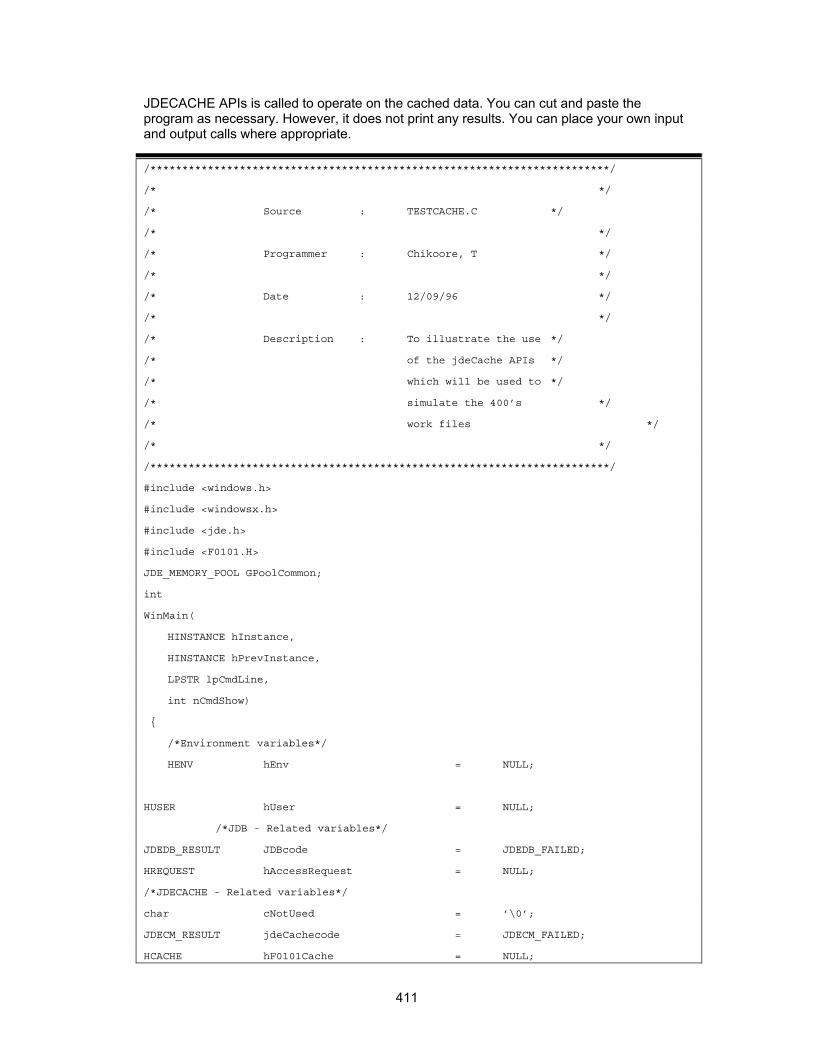
JDECACHE APIs is called to operate on the cached data. You can cut and paste the program as necessary. However, it does not print any results. You can place your own input and output calls where appropriate.
/************************************************************************/
/* */
/* Source : TESTCACHE.C */
/* */
/* Programmer : Chikoore, T */
/* */
/* Date : 12/09/96 */
/* */
/* Description : To illustrate the use */
/* of the jdeCache APIs */
/* which will be used to */
/* simulate the 400’s */
/* work files */
/* */
/************************************************************************/
#include <windows.h>
#include <windowsx.h>
#include <jde.h>
#include <F0101.H>
JDE_MEMORY_POOL GPoolCommon;
int
WinMain(
HINSTANCE hInstance,
HINSTANCE hPrevInstance,
LPSTR lpCmdLine,
int nCmdShow)
{
/*Environment variables*/
HENV hEnv = NULL;
HUSER hUser = NULL;
/*JDB - Related variables*/
JDEDB_RESULT JDBcode = JDEDB_FAILED;
HREQUEST hAccessRequest = NULL;
/*JDECACHE - Related variables*/
char cNotUsed = ’\0’;
JDECM_RESULT jdeCachecode = JDECM_FAILED;
HCACHE hF0101Cache = NULL;
411

HJDECURSOR hF0101CacheCursor1 = NULL;
HJDECURSOR hF0101CacheCursor2 = NULL;
JDECMINDEXSTRUCT Index[1];
/*Table - Related variables*/
ID idTable = ID_F0101;
F0101 dsInsertStruct,dsRetrieveStruct,f0101;
/*Just variables*/
KEY1_F0101 dsF0101CacheKey;
short int nNumColsInIndex = 1;
short int nCursor1FetchCounter = 0;
short int nCursor2FetchCounter = 0;
/*********************************************************************/
/* */
/* Section 1 */
/* */
/* Initialize the JDB and USER environments as usual */
/* The cache environment is implicitly initialized by the */
/* JDB_InitEnv API, you do not have to worry about it */
/* */
/*********************************************************************/
/*Initialize the JDE memory pool management utility*/
GPoolCommon = jdeMemoryManagementInit();
/*Initalize the Environment*/
JDBcode = JDB_InitEnv(&hEnv);
if(JDBcode != JDEDB_PASSED)
{
jdeMemoryManagementTerminate();
return 0;
} /*END IF*/
/*initialize the User*/
JDBcode = JDB_InitUser(hEnv,&hUser,”P0101”,JDEDB_COMMIT_AUTO);
if(JDBcode != JDEDB_PASSED)
{
JDB_FreeEnv(hEnv);
jdeMemoryManagementTerminate();
return 0;
} /*END IF*/
/******************************************************************/
/* */
/* Section 2 */
412

/* */
/* Set up the index key that will be used to access the cache. */
/* One and only one index is allowed per cache. */
/* */
/* CODE: Here the address book number (aban8) is being */
/* set up as the key. */
/* */
/* */
/******************************************************************/
/*Initialize the structure*/
memset(&Index,0x00,sizeof(JDECMINDEXSTRUCT));
/*Set up the cache index*/
Index->nKeyID = 1;
Index->nNumSegments = 1;
Index->CacheKey[0].nOffset = offsetof(F0101, aban8);
Index->CacheKey[0].nSize = sizeof(f0101.aban8);
Index->CacheKey[0].idDataType = EVDT_MATH_NUMERIC;
/******************************************************************/
/* */
/* Section 3 */
/* */
/* Initialize the cache. The address of the cache handle */
/* for that particular cache is passed as well as the */
/* cache name and index. The cache handle will be use to */
/* identify this particular cache when calling any of the */
/* cache APIs */
/* */
/* CODE: The cache named F0101 is being initialized */
/* */
/* */
/******************************************************************/
/*Initialize the user cache*/
jdeCachecode = jdeCacheInit(hUser, &hF0101Cache, ”F0101”,Index);
if(jdeCachecode != JDECM_PASSED)
{
JDB_FreeUser(hUser);
JDB_FreeEnv(hEnv);
jdeMemoryManagementTerminate();
return 0;
} /*END IF*/
/**********************************************************************/
413

/* */
/* Section 4 */
/* */
/* CODE: We are going to open the address book table */
/* (F0101)and place the contents of the whole table */
/* into the F0101cache which we have just initalized */
/* in Section 3. */
/* */
/**********************************************************************/
/*Open the address book table*/
JDBcode = JDB_OpenTable(hUser, idTable, 0, NULL, 0 ,NULL,&hAccessRequest);
if(JDBcode != JDEDB_PASSED)
{
jdeCacheTerminate(hUser, hF0101Cache);
JDB_FreeUser(hUser);
JDB_FreeEnv(hEnv);
jdeMemoryManagementTerminate();
return 0;
} /*END IF*/
/*Select all rows of the address book*/
JDBcode = JDB_SelectAll(hAccessRequest);
if (JDBcode != JDEDB_PASSED)
{
jdeCacheTerminate(hUser, hF0101Cache);
JDB_CloseTable(hAccessRequest);
JDB_FreeUser(hUser);
JDB_FreeEnv(hEnv);
jdeMemoryManagementTerminate();
return 0;
} /*END IF*/
/*Initialize the structure*/
memset(&dsInsertStruct,0x00,sizeof(F0101));
/*Fetch all rows of the address book*/
while (JDB_Fetch(hAccessRequest, &dsInsertStruct, FALSE) == JDEDB_PASSED)
{
/*Add the row to the cache*/
jdeCachecode = jdeCacheAdd(hF0101Cache, (void *) &dsInsertStruct, (long int)
sizeof(F0101));
if(jdeCachecode == JDECM_FAILED)
{
414
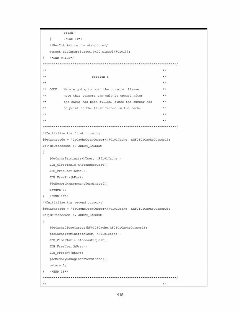
break;
} /*END IF*/
/*Re-Initialize the structure*/
memset(&dsInsertStruct,0x00,sizeof(F0101));
} /*END WHILE*/
/**********************************************************************/
/* */
/* Section 5 */
/* */
/* CODE: We are going to open the cursors. Please */
/* note that cursors can only be opened after */
/* the cache has been filled, since the cursor has */
/* to point to the first record in the cache */
/* */
/* */
/**********************************************************************/
/*Initialize the first cursor*/
jdeCachecode = jdeCacheOpenCursor(hF0101Cache, &hF0101CacheCursor1);
if(jdeCachecode != JDECM_PASSED)
{
jdeCacheTerminate(hUser, hF0101Cache);
JDB_CloseTable(hAccessRequest);
JDB_FreeUser(hUser);
JDB_FreeEnv(hEnv);
jdeMemoryManagementTerminate();
return 0;
} /*END IF*/
/*Initialize the second cursor*/
jdeCachecode = jdeCacheOpenCursor(hF0101Cache, &hF0101CacheCursor2);
if(jdeCachecode != JDECM_PASSED)
{
jdeCacheCloseCursor(hF0101Cache,hF0101CacheCursor1);
jdeCacheTerminate(hUser, hF0101Cache);
JDB_CloseTable(hAccessRequest);
JDB_FreeUser(hUser);
JDB_FreeEnv(hEnv);
jdeMemoryManagementTerminate();
return 0;
} /*END IF*/
/**********************************************************************/
/* */
415
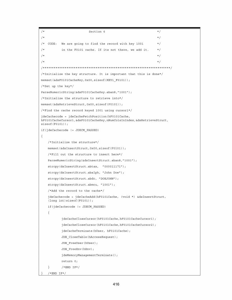
/* Section 6 */
/* */
/* CODE: We are going to find the record with key 1001 */
/* in the F0101 cache. If its not there, we add it. */
/* */
/* */
/**********************************************************************/
/*Initialize the key structure. It is important that this is done*/
memset(&dsF0101CacheKey,0x00,sizeof(KEY1_F0101));
/*Set up the key*/
ParseNumericString(&dsF0101CacheKey.aban8,”1001”);
/*Initialize the structure to retrieve into*/
memset(&dsRetrieveStruct,0x00,sizeof(F0101));
/*Find the cache record keyed 1001 using cursor1*/
jdeCachecode = jdeCacheFetchPosition(hF0101Cache, hF0101CacheCursor1,&dsF0101CacheKey,nNumColsInIndex,&dsRetrieveStruct, sizeof(F0101));
if(jdeCachecode != JDECM_PASSED)
{
/*Initialize the structure*/
memset(&dsInsertStruct,0x00,sizeof(F0101));
/*Fill out the structure to insert here*/
ParseNumericString(&dsInsertStruct.aban8,”1001”);
strcpy(dsInsertStruct.abtax, ”000011171”);
strcpy(dsInsertStruct.abalph, ”John Doe”);
strcpy(dsInsertStruct.abdc, ”DOEJOHN”);
strcpy(dsInsertStruct.abmcu, ”1001”);
/*Add the record to the cache*/
jdeCachecode = jdeCacheAdd(hF0101Cache, (void *) &dsInsertStruct, (long int)sizeof(F0101));
if(jdeCachecode != JDECM_PASSED)
{
jdeCacheCloseCursor(hF0101Cache,hF0101CacheCursor1);
jdeCacheCloseCursor(hF0101Cache,hF0101CacheCursor2);
jdeCacheTerminate(hUser, hF0101Cache);
JDB_CloseTable(hAccessRequest);
JDB_FreeUser(hUser);
JDB_FreeEnv(hEnv);
jdeMemoryManagementTerminate();
return 0;
} /*END IF*/
} /*END IF*/
416

/**********************************************************************/
/* Section 7 */
/* */
/* CODE: We are going to update the record with key 1002 */
/* in the F0101 cache. */
/* */
/* */
/**********************************************************************/
/*Set up the key*/
ParseNumericString(&dsF0101CacheKey.aban8,”1002”);
/*Find the cache record keyed 1002 using cursor1 and keep the cursor
pointing to that record because we want to update it*/
jdeCachecode = jdeCacheFetchPosition(hF0101Cache, hF0101CacheCursor1, &dsF0101CacheKey, nNumColsInIndex,&dsRetrieveStruct, sizeof(F0101));
if(jdeCachecode != JDECM_PASSED)
{
jdeCacheCloseCursor(hF0101Cache,hF0101CacheCursor1);
jdeCacheCloseCursor(hF0101Cache,hF0101CacheCursor2);
jdeCacheTerminate(hUser, hF0101Cache);
JDB_CloseTable(hAccessRequest);
JDB_FreeUser(hUser);
JDB_FreeEnv(hEnv);
jdeMemoryManagementTerminate();
return 0;
}
/*Update the structure we have just retrieved here*/
strcpy(dsRetrieveStruct.abalph, ”Put Alpha Name Here”);
/*Update the record with the record just retrieved. The cursor is already pointing to this record so we do not need a key*/
jdeCachecode =jdeCacheUpdate(hF0101Cache, hF0101CacheCursor1, &dsRetrieveStruct,sizeof(KEY1_F0101));
if(jdeCachecode != JDECM_PASSED)
{
jdeCacheCloseCursor(hF0101Cache,hF0101CacheCursor1);
jdeCacheCloseCursor(hF0101Cache,hF0101CacheCursor2);
jdeCacheTerminate(hUser, hF0101Cache);
JDB_CloseTable(hAccessRequest);
JDB_FreeUser(hUser);
JDB_FreeEnv(hEnv);
jdeMemoryManagementTerminate();
return 0;
} /*END IF*/
417

/**********************************************************************/
/* */
/* Section 8 */
/* */
/* CODE: We are going to delete the record with key 1001 */
/* in the F0101 cache. */
/* */
/* */
/* */
/**********************************************************************/
/*Set up the key*/
ParseNumericString(&dsF0101CacheKey.aban8,”1001”);
/*Find the cache record keyed 1002 using cursor1 and keep the cursor pointing to that record because we want to update it*/
jdeCachecode = jdeCacheFetchPosition(hF0101Cache, hF0101CacheCursor1, &dsF0101CacheKey,nNumColsInIndex,&dsRetrieveStruct,sizeof(F0101));
if(jdeCachecode != JDECM_PASSED)
{
jdeCacheCloseCursor(hF0101Cache,hF0101CacheCursor1);
jdeCacheCloseCursor(hF0101Cache,hF0101CacheCursor2);
jdeCacheTerminate(hUser, hF0101Cache);
JDB_CloseTable(hAccessRequest);
JDB_FreeUser(hUser);
JDB_FreeEnv(hEnv);
jdeMemoryManagementTerminate();
return 0;
}
/*Delete the record keyed 1001 using cursor 1.*/
jdeCachecode = jdeCacheDelete(hF0101Cache, hF0101CacheCursor1);
if(jdeCachecode != JDECM_PASSED)
{
jdeCacheCloseCursor(hF0101Cache,hF0101CacheCursor1);
jdeCacheCloseCursor(hF0101Cache,hF0101CacheCursor2);
jdeCacheTerminate(hUser, hF0101Cache);
JDB_CloseTable(hAccessRequest);
JDB_FreeUser(hUser);
JDB_FreeEnv(hEnv);
jdeMemoryManagementTerminate();
return 0;
} /*END IF*/
/**********************************************************************/
/* */
418
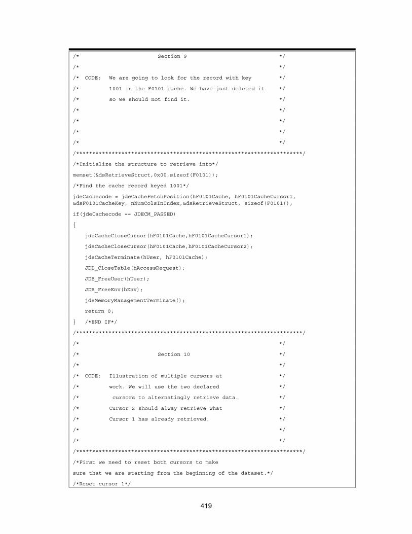
/* Section 9 */
/* */
/* CODE: We are going to look for the record with key */
/* 1001 in the F0101 cache. We have just deleted it */
/* so we should not find it. */
/* */
/* */
/* */
/* */
/**********************************************************************/
/*Initialize the structure to retrieve into*/
memset(&dsRetrieveStruct,0x00,sizeof(F0101));
/*Find the cache record keyed 1001*/
jdeCachecode = jdeCacheFetchPosition(hF0101Cache, hF0101CacheCursor1, &dsF0101CacheKey, nNumColsInIndex,&dsRetrieveStruct, sizeof(F0101));
if(jdeCachecode == JDECM_PASSED)
{
jdeCacheCloseCursor(hF0101Cache,hF0101CacheCursor1);
jdeCacheCloseCursor(hF0101Cache,hF0101CacheCursor2);
jdeCacheTerminate(hUser, hF0101Cache);
JDB_CloseTable(hAccessRequest);
JDB_FreeUser(hUser);
JDB_FreeEnv(hEnv);
jdeMemoryManagementTerminate();
return 0;
} /*END IF*/
/**********************************************************************/
/* */
/* Section 10 */
/* */
/* CODE: Illustration of multiple cursors at */
/* work. We will use the two declared */
/* cursors to alternatingly retrieve data. */
/* Cursor 2 should alway retrieve what */
/* Cursor 1 has already retrieved. */
/* */
/* */
/**********************************************************************/
/*First we need to reset both cursors to make
sure that we are starting from the beginning of the dataset.*/
/*Reset cursor 1*/
419

jdeCachecode = jdeCacheResetCursor(hF0101Cache, hF0101CacheCursor1);
if(jdeCachecode != JDECM_PASSED)
{
/*reset failed*/
jdeCacheCloseCursor(hF0101Cache,hF0101CacheCursor1);
jdeCacheCloseCursor(hF0101Cache,hF0101CacheCursor2);
jdeCacheTerminate(hUser, hF0101Cache);
JDB_CloseTable(hAccessRequest);
JDB_FreeUser(hUser);
JDB_FreeEnv(hEnv);
jdeMemoryManagementTerminate();
return 0;
}
/*Reset cursor 2*/
jdeCachecode = jdeCacheResetCursor(hF0101Cache, hF0101CacheCursor2);
if(jdeCachecode != JDECM_PASSED)
{
/*reset failed*/
jdeCacheCloseCursor(hF0101Cache,hF0101CacheCursor1);
jdeCacheCloseCursor(hF0101Cache,hF0101CacheCursor2);
jdeCacheTerminate(hUser, hF0101Cache);
JDB_CloseTable(hAccessRequest);
JDB_FreeUser(hUser);
JDB_FreeEnv(hEnv);
jdeMemoryManagementTerminate();
return 0;
}
/*Clear the structure we are to retrieve records into*/
memset(&dsRetrieveStruct,0x00,sizeof(F0101));
/*Initialize the counter associted with cursor1*/
nCursor1FetchCounter=0;
/*Fetch the next record using cursor 1*/
while(jdeCacheFetch(hF0101Cache,hF0101CacheCursor1,&dsRetrieveStruct,NULL) != JDECM_FAILED)
{
/*Increment the counter associted with cursor1*/
nCursor1FetchCounter++;
/*Check if cursor 1 has reached the max number of fetches*/
if(nCursor1FetchCounter == 2)
{
/*Initialize the counter associted with cursor1*/
420

nCursor2FetchCounter = 0;
/*Fetch the next record using cursor 2*/
while(jdeCacheFetch(hF0101Cache,hF0101CacheCursor2, &dsRetrieveStruct,NULL) != JDECM_FAILED)
} /*END IF*/
} /*END WHILE*/
/**********************************************************************/
/* */
/* Section 11 */
/* */
/* CODE: END!!! */
/* Do the normal clean up work. */
/* */
/* */
/**********************************************************************/
/*First close all open cursor before terminating the cache*/
/*Close open cursor 1*/
jdeCacheCloseCursor(hF0101Cache,hF0101CacheCursor1);
/*Close open cursor 2*/
jdeCacheCloseCursor(hF0101Cache,hF0101CacheCursor2);
jdeCachecode = jdeCacheTerminate(hUser,hF0101Cache);
if(jdeCachecode != JDECM_PASSED)
{
/*This is just a check for failure otherwise its the same as below*/
JDB_CloseTable(hAccessRequest);
JDB_FreeUser(hUser);
JDB_FreeEnv(hEnv);
jdeMemoryManagementTerminate();
return 0;
} /*END IF*/
/*Close the table*/
JDBcode = JDB_CloseTable(hAccessRequest);
/*Free the user*/
JDBcode = JDB_FreeUser(hUser);
/*Free the environment, the cache is implicitly killed here*/
JDBcode = JDB_FreeEnv(hEnv);
/*Terminate the memory management utility*/
jdeMemoryManagementTerminate();
return(0);
421

}
JDECACHE Standards
J.D. Edwards has standards for using cache that you are encouraged to follow.
Cache Business Function Source Name The cache business function name should follow the standard naming convention for business functions.
Cache Business Function Source Description The following standards apply to cache business function source descriptions:
• The cache business function description follows the business function description standards.
• The first word must be the noun Cache.
• The second word must be the verb Process.
• For an individual cache function, the words following Process should describe the cache. For a common cache function, the words following Process should describe the group to which the individual cache functions belong.
Example Individual Cache Functions
• Cache Process Rating Options and Equipment
• Cache Process Rating Shipment Pieces
• Cache Process All Components Cache
The following standards apply to cache business function descriptions:
Example Group Cache Functions
• Cache Process Transportation Cache
• Cache Process Product Data Management Cache
• Cache Process Configurator Cache
Cache Business Function Description
• If the source file contains an individual function, the function name should match the source name.
• If the source file contains a group of cache functions, the individual function names should follow the same standards as the Cache Business Function Source Description standards for individual cache function description.
422

Cache Programming Standards
General Standards Two types of standard cache functions exist: the individual cache function and the group cache function. An individual cache function is a single business function that acts as the file server over a single cache. A group cache function is a single business function that acts as the file server over several predefined caches. The following general standards apply to cache programming:
• Use cache APIs only within a standardized cache function. Using the standard cache function allows you to easily create and maintain code. The standard functions simplify the use of cache.
• Ensure that the cache function contains the standard cache actions. You can also include additional actions against cache that are specific to the cache.
• Use a cache function to initialize the cache, load cache, retrieve records from cache, delete records from cache, modify records, and terminate the cache.
You either terminate the cache or clear it, depending on whether the cache needs to remain available. This decision is specific to the design of your application.
• The cache name is a maximum of 50 characters.
• If the cache will be terminated, the cache name should include the job number.
Terminating versus Clearing Cache
Before terminating the cache, free memory of cache data structures, if necessary. Cache data structures are different from cache index structures. Terminating the cache frees cache index structures but does not affect cache data structures.
Cache Name The following standards apply to the cache name:
• Depending on how the cache is used, the cache name should either be the data structure name or the data structure name with the job number appended to it.
• When cache is used in master business functions, the cache is not terminated by the application. The job number is stored as a key in the cache. Instead of terminating the cache, all records containing the job number are cleared at the end of the transaction. The cache is not terminated due to the asynchronous processing. In this case, the cache name should contain only the data structure name.
Defining the Cache Data Structure
• Group Cache Function
The data structure for the cache function is also the layout and index for the individual cache. Typedef the data structure and paste it in the business function header file.
• Individual Cache Function
The cache layout and cache index for an individual cache function should be defined in the business function header file.
423

Data Structure Standard Data Items The following data items are standard to every Cache Business Function. These data items should be the first data items in the data structure.
• NACTN - Cache Action Code
• NKEYS - Number of Keys
• CURSOR - Cache Cursor
• DTAI - Error Message ID
• JOBS - Job Number (optional)
Additional data items that pass the information stored in cache should follow the standard data items. Preferably, the key fields are listed first, in order of the cache index.
Cache Action Code Standards The following CACHE action codes are standard.
CACHE_GET
• Opens cursor.
• Fetches a single record from the cache using the jdeCacheFetch API.
Fetch can be with either a full or partial key. The number of keys used is passed to the function through the business function data structure standard data items.
• Cache cursor is not required to perform the fetch, and the cache cursor will not be returned after the record is fetched.
• Returns success or failure.
CACHE_ADD
• Inserts a record into cache using the jdeCacheAdd API.
• Full key must be defined, and values for all key fields must be passed.
• Duplicate records are not allowed in cache.
• Cache cursor is not required to add a record to cache, and the cache cursor will not be returned after the record is added.
• Returns success or failure.
CACHE_UPDATE
• Opens cursor.
• Optionally, fetches the record for update from cache using the jdeCacheFetchPosition API.
• Updates the fetched record using the jdeCacheUpdate API.
• Full key must be defined, and values for all key fields must be passed.
• Cache cursor is not required to update a record in cache, and the cache cursor will not be returned.
• Returns success or failure.
424

CACHE_ADD_UPDATE
• If a record exists, the record delete it and replace it with the new record. If a record does not exist, add it.
• First, fetch the record using the jdeCacheFetch API. If a record was found, delete it using the jdeCacheDelete API. Add the new record with the values passed through the business function data structure using the jdeCacheAdd API.
• Full key must be defined, and all values for the key fields must be passed.
• The cache cursor is not required, and the cache cursor is not returned.
• Returns success or failure on the new record being added.
CACHE_DELETE
• Deletes one record, a set of records, or all records from cache, depending on the number of keys passed.
• If the number of keys is equal to the total number of keys in the index, a single record will be deleted from cache using jdeCacheDelete API.
• A set of records may be deleted from cache by defining a partial key. Records are deleted using jdeCacheDelete API.
• All records will be deleted from cache if the number of keys is set to zero. Records are deleted using jdeCacheDeleteAll API.
• Cache cursor is not required to delete a record from cache, and the cache cursor will not be returned.
• Returns success or failure.
CACHE_GET_NEXT
• If the cache cursor is empty, open the cursor, then fetch the first record using jdeCacheFetchPosition.
• If the cursor contains a value, fetch the next record.
• Pass a full or partial key. The number of keys must remain constant.
• To determine the end of file, compare the value of the defined number of keys in the previous record with the next record.
• Matching partial keys for the Group Cache function is more difficult.
• Close the cursor when key match fails and free the data pointer.
CACHE_TERMINATE Terminates the cache using the jdeCacheTerminate API. The cache is terminated only when the number of users of the cache equals zero.
CACHE_TERMINATE_ALL
• Terminates the cache using the jdeCacheTerminateAll API.
• Free the data pointer.
• Regardless of the number of users accessing the cache, it will be terminated.
425
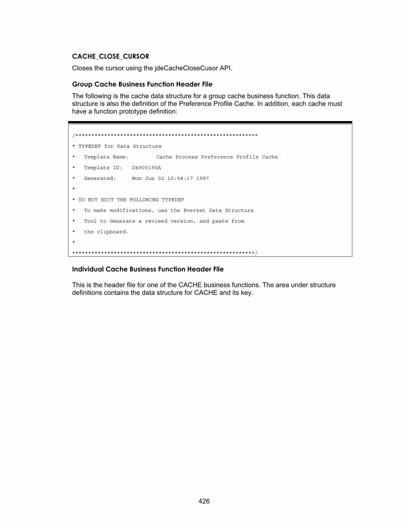
CACHE_CLOSE_CURSOR Closes the cursor using the jdeCacheCloseCusor API.
Group Cache Business Function Header File The following is the cache data structure for a group cache business function. This data structure is also the definition of the Preference Profile Cache. In addition, each cache must have a function prototype definition:
/*********************************************************
* TYPEDEF for Data Structure
* Template Name: Cache Process Preference Profile Cache
* Template ID: D4900190A
* Generated: Mon Jun 02 10:54:17 1997
*
* DO NOT EDIT THE FOLLOWING TYPEDEF
* To make modifications, use the Everest Data Structure
* Tool to Generate a revised version, and paste from
* the clipboard.
*
*********************************************************/
Individual Cache Business Function Header File
This is the header file for one of the CACHE business functions. The area under structure definitions contains the data structure for CACHE and its key.
426
Additional Features
Processing Options
Processing options control how an interactive or batch application processes data. You can use processing options to change the way in which an application or a report appears or behaves. You can attach unique processing options to different versions of the same application, which allows you to change the behavior of an application without creating a new application. You can use processing options to do the following:
• Control the path that a user can use to travel through a system
• Set up default values
• Customize an application for different companies or even different users
• Control the format of forms and reports
• Control page breaks and totaling for reports
• Specify the default version of an application or batch process
You can define processing options for an application that automatically appear at runtime.
In addition, you might need to create a processing option version. The procedures for creating a processing option version are comparable to those for creating an interactive version.
Processing Options Templates
A processing options template contains one or more processing options. Each processing option appears on a row within the template and is defined by the following three variables:
Tab Title A title that categorizes processing options. This text appears on the tab for a processing option.
Comment Optional, additional text that appears on the form with the processing options. Each comment takes the place of a processing option on the page. Adding a comment eliminates space for a processing option.
Data Item An entry in the data dictionary. Every processing option must be a data item in the data dictionary. Select data items for which you want to automatically assign default values, such as cost center ranges and dates.
At runtime, a processing option template displays a set of tabs within an area called a page. Each tab represents a category of processing options. When you click the tab, the page changes to show the set of processing options for that category.
Caution Changes to processing option text can conflict with changes to processing option templates. Template changes do not take effect until another package is built, but text changes occur immediately.
427
The following steps describe how to create and implement processing options:
1. Create processing options by building a list of parameters called a template.
2. Attach this template to an application and create event rules so that the application uses these values.
3. Create versions of the application.
4. Specify how the processing options are handled at runtime.
At runtime, depending on how you set up the application, one of the following events occurs:
• The processing options appear, and the user can choose processing options and to supply values.
• A version list appears from which the user can choose a version.
• The application runs with a preselected set of options.
Processing option templates are stored in specification tables. Data values are stored in the Versions list table (F983051). The processing option template and the processing option text are stored in the POTEXT TAM file until you check in the processing option template. Then, the processing option data is stored as a single T object in the Processing Option Text table (F98306). For batch versions, the F983051 table has an identifier that points to specifications for overrides (report overrides, data sequencing, data selection, or override location).
Each version of an application can be associated with a list of processing option values. The processing options that are specified at the time that an interactive or batch application is launched are those that the application uses when it executes. This sequence prevents users from changing processing options between the time that a batch application is submitted and the time it actually executes. Processing options can also be used for a specific execution of an application. These processing options are not permanently stored in the F983051 table, and they are used only for that specific execution.
Defining a Processing Options Data Structure (Template)
You can create a processing options data structure (template) that lists the values for data items passed to the application at runtime. Any changes that you make to the template reside on your workstation until you check in the template. This ensures that current users of the template are not immediately affected by your changes. After you check in your changes, the next JITI replicates the changes to the users.
Before You Begin Create a processing options data structure. See Creating a Processing Options Data
Structure.
Defining a Template
Use the following process to determine how a processing options data structure looks and behaves. The structure itself must already exist. See Creating a Processing Options Data Structure for detailed instructions for creating the template object.
428

► To define a processing options data structure (template)
1. On Object Management Workbench, check out the processing options data structure with which you want to work.
2. Ensure that the data structure is highlighted, and then click the Design button in the center column.
3. On Processing Option Design, click the Design Tools tab, and then click Start the Processing Option Design Aid.
The Processing Options Design tool launches. The area on the left of the form displays how the processing option will look to the user.
4. Use one of the following methods to choose the data items that you wish to add to your processing options:
• Double-click on the item in the Data Dictionary Browser, and the item will appear in the left side of the form under the tab.
• Drag the item from the Data Dictionary Browser to the position where you want it in the structure members.
5. Click an item to edit it.
• Use the hatching around the control to reposition it.
• Select text, and delete or overwrite it.
Processing Options Design automatically adjusts the size and position of data items to fit the width of the tab.
429

6. Choose the text button (A) to add comments.
7. Choose an object in the area on the left side of the form, and choose Properties from the View menu.
430

If you are on a data item, you can view its properties and change the Item Name if necessary. The Item Name should be unique.
You can click the Help Override Data Item tab to add an alternate szDict from which to get the help.
8. To view tab properties, click on the tab and choose Properties from the View menu.
You can also right-click on a tab and choose Current Tab Properties from the menu that appears.
If you are on a tab item, you can can enter a short and long name for the tab.
Use the Help File Name field to add the name of the help file for the tab.
9. To add a new tab, choose New Tab from the File menu.
You can also right-click on an existing tab and choose New Tab from the menu that appears.
431

J. D. Edwards Processing Option Naming Standards
You should follow J.D. Edwards naming standards wherever possible, unless you have a strong business case that supports the need to change. Following the naming standards ensures a consistent approach to programming.
Processing Option Data Structure
The Object Librarian name for a data structure can be a maximum of 10 or 9 characters (depending on whether you begin with T) and may be formatted as follows: Txxxxxyyyy
T = Processing option data structure
xxxxxyyyy = The program number for the application or report
For example, the data structure name for the P0101 application is T0101.
• Ensure that each tab exists only once and that it is not divided into multiple tabs. For example, use Process instead of Process 1, Process 2.
Tab Title
Use the following guidelines when you define a tab title for a processing option:
• Avoid abbreviating tab titles wherever possible.
• For future processing options, indicate that they are currently unavailable by entering the word FUTURE. If the entire tab is unavailable, enter FUTURE behind the extended description for the tab. If a single processing option is unavailable, place FUTURE behind the data item description.
• Include the application name, such as P4310, in the text when referencing versions that are to be used. The Version tab should always begin with the comment block, "Enter the version to be used for each program. If left blank, ZJDE0001 will be used."
• Use application-specific tabs sparingly and only when no other category are appropriate. The name of an application-specific tab should be no longer than 10 characters in English to allow for translation.
• Use one of the eight standard tab titles. Along with the extended description and processing options for each, they are as follows:
Display: Display Options determines whether a field appears or which format of a form appears on entry.
Defaults: Default Values assigns a default value to a field.
Edits: Data Edits indicates whether a validation is to be performed.
Process: Process Control controls the process flow of the application.
Application-specific tabs are:
Currency: Currency Options contains processing options that are specific to currency.
Categories: Category Codes indicates default category codes.
Print: Print Options controls the output of a report.
432
Versions: Versions to Execute contains versions of the application that are called from this application.
The following are standard application-specific tab titles. Group processing options under these tab titles when they apply to the type of processing specified in the tab.
Manufacturing and Distribution Equipment Mgt - Equipment Management
Financials Taxes: Tax Processing contains processing options that are specific to taxes.
Comment
When entering a comment for a processing option, use the following guidelines:
• Number every option on a tab. Use sequential numbering, starting at 1, for each tab.
Note When several processing options are grouped together, you can choose to number the processing options or the comments. Choose whatever works best for the situation.
• Use nouns, such as Customer Master, to describe the processing option. The action
required is defined in the glossary for that processing option.
• Add the text Required to the end of the processing option if a processing option is required.
• Use a comment block when multiple processing options refer to the same topic. The comment block is a title for the logical group of processing options.
Data Item
When selecting a data item for a processing option, use the following guidelines:
• When necessary, change the name of the data item to be descriptive.
• When renaming the data item element, the field element should comply with the naming standards for event rule variables with the alias appended, such as szCategoryCode3_CT03.
• Use a relevant data item when the data dictionary glossary applies. The user can display the glossary from the processing options. Do not use generic work fields, such as EV01.
Language Considerations for Processing Options
You can change a processing option template to incorporate language features.
433

► To change a template for text translation
From System Administration Tools (GH9011), choose Processing Options Text Translation.
1. On Work With PO Text Translations, choose the processing option template that you want to change.
Work with PO Text Translations displays processing option text for the processing option template and language that you specify in the filter fields.
2. Select the item that you want to change and enter the new text.
You can change a tab.
434
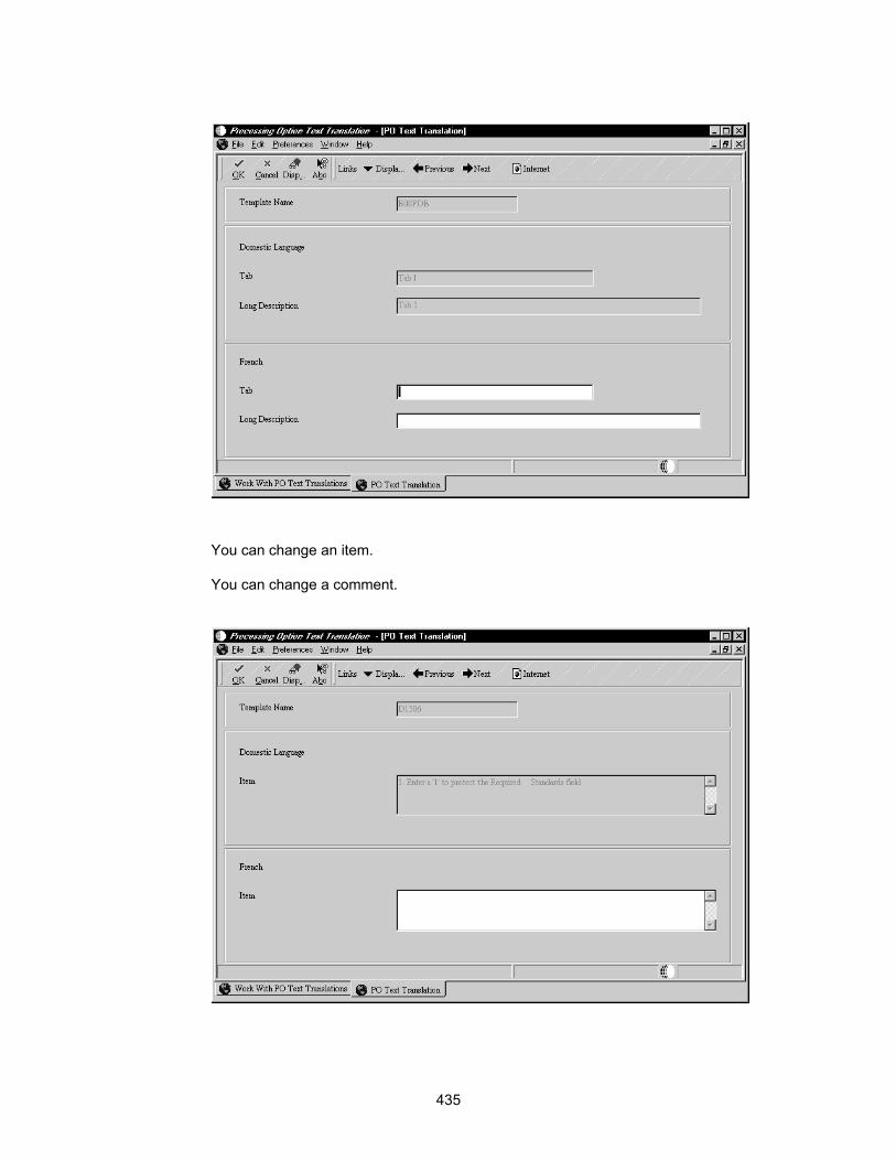
You can change an item.
You can change a comment.
435

► To add a template with translated text
When you add a new processing option template for an application that is language-enabled, complete the following tasks:
1. Create the application.
2. Create the Processing Template for the base language.
3. Add the language text.
Attaching a Processing Options Template
You must attach a processing options template (data structure) to an application to enable processing options at runtime. You can use processing options to set up default values, control formats, control report breaks, control totaling, and control how a report processes data. A processing option template has the following characteristics:
• It exists as a separate object
• It can be attached to multiple applications
When you attach a processing options template, if one or more of the processing options is designed to process on a certain event, you must attach event rule logic to enable the processing option.
► To attach a processing options template
1. On Application Design Aid, from the Form menu, choose Design.
2. From the Application menu, choose Select Processing Options.
3. On Select Processing Option Template, choose the processing option template that you want to use and click OK.
Caution The versions of an application and the event rules attached to depend on the block of data passed to the application by way of a specific processing option template. If you
436
disconnect that template from the application or connect a different template to the application, the application might not run properly.
To change the processing option template, first remove all existing versions of the application. Then, examine all application objects for event rules to ensure that the data that they need will still be available after you change or remove the template.
Transaction Processing
A transaction is a logical unit of work (comprised of one or more SQL statements) performed on the database to complete a common task and maintain data consistency. Transaction statements are closely related and perform interdependent actions. Each statement performs part of the task, but all of them are required for the complete task.
Transaction Processing ensures that related data is added to or deleted from the database simultaneously, thus preserving data integrity in your application. In transaction processing, data is not written to the database until a commit command is issued. When this happens, data is permanently written to the database.
For example, if a transaction comprises database operations to update two database tables, either all updates will be made to both tables, or no updates will be made to either table. This condition guarantees that the data remains in a consistent state and the integrity of the data is maintained.
You see a consistent view of the database during a transaction. You do not see changes from other users during a transaction.
Transaction Processing ensures that transactions are:
• Atomic - Either all database changes for an entire transaction are completed or none of the changes are completed.
• Consistent - Database changes transform from one consistent database state to another.
• Isolated - Transactions from concurrent applications do not interfere with each other. The updates from a transaction are not visible to other transactions that execute concurrently until the transaction commits.
• Durable - Complete database operations are permanently written to the database.
Commits and Rollbacks
The scope of a transaction is defined by the beginning and the end of the transaction. The end of a transaction occurs when the transaction is committed or rolled back. If neither a commit nor a rollback of a transaction occurs, the transaction rolls back when you exit OneWorld.
Transaction processing uses commits to control database operations. Commits are commands to the database. Transactions can be automatically or manually committed. For automatic commits, database changes are written permanently to the database (committed) as they are executed. For manual commits, database changes are written permanently to the database only when either a commit or a rollback occurs.
437

Commit A commit is an explicit command to the database to permanently store the results of operations performed by a statement. This event successfully ends a transaction.
Two-Phase Commit (Manual Commit Mode) A two-phase commit coordinates a distributed transaction. It occurs only when at least one update statement has been executed to two separate data sources in the same transaction.
Rollback A rollback is an explicit command to the database to cancel the results of operations performed by a statement. This event indicates that a transaction ended unsuccessfully.
Any failure of an insert, update, or delete within a transaction boundary causes all record activity within that transaction to roll back. If no failures have occurred at the end of the transaction, a commit is done, and the records become available to other processes.
In the case of a catastrophic failure (such as network problems), the DBMS performs an automatic rollback. If the user clicks Cancel on a form, a rollback command is issued through a system function.
Understanding Transaction Processing
A OneWorld transaction is a logical unit of work (comprised of one or more SQL statements) performed on any number of databases. A single-statement transaction consists of one statement, and a multiple-statement transaction consists of more than one statement.
You can construct a transaction within a OneWorld application to group multiple database operations. The application can then request the database management system to buffer the database operations until the application executes a specific command to perform the updates requested within the transaction. Database operations that are not part of a transaction update the database immediately.
If an application has transaction processing turned on, you cannot see updated records until an update has been committed. Only processes within that transaction can access records in the transaction until the transaction is complete.
The OneWorld Application Design tool allows you to enable an application for transaction processing and to define which database operations comprise a transaction. Not all transactions or applications must be enabled. Enable transaction or applications appropriately, according to your database configuration.
If transaction processing is turned on for database operations for tables that reside in DB2, then those tables must be journaled. Journaling can decrease performance because of the additional processing required. Contact your DB2 administrator if you have problems with this process.
General messages and errors for transaction processing are written to the jde.log or jdedebug.log.
Data Interdependence Data interdependence refers to the data elements that make a transaction complete. For example, a voucher has records in both the Accounts Payable Ledger table (F0411) and the Account Ledger table (F0911). Because no data interdependence exists between the two tables, the transaction is incomplete when data exists in one table and not the other.
438
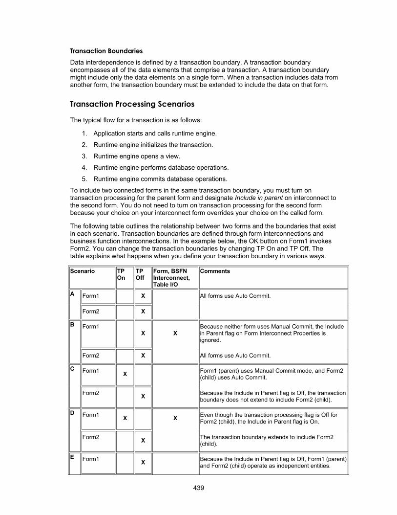
Transaction Boundaries Data interdependence is defined by a transaction boundary. A transaction boundary encompasses all of the data elements that comprise a transaction. A transaction boundary might include only the data elements on a single form. When a transaction includes data from another form, the transaction boundary must be extended to include the data on that form.
Transaction Processing Scenarios
The typical flow for a transaction is as follows:
1. Application starts and calls runtime engine.
2. Runtime engine initializes the transaction.
3. Runtime engine opens a view.
4. Runtime engine performs database operations.
5. Runtime engine commits database operations.
To include two connected forms in the same transaction boundary, you must turn on transaction processing for the parent form and designate Include in parent on interconnect to the second form. You do not need to turn on transaction processing for the second form because your choice on your interconnect form overrides your choice on the called form.
The following table outlines the relationship between two forms and the boundaries that exist in each scenario. Transaction boundaries are defined through form interconnections and business function interconnections. In the example below, the OK button on Form1 invokes Form2. You can change the transaction boundaries by changing TP On and TP Off. The table explains what happens when you define your transaction boundary in various ways.
Scenario TP On
TP Off
Form, BSFN Interconnect, Table I/O
Comments
A Form1 X All forms use Auto Commit.
Form2 X
B Form1 X X
Because neither form uses Manual Commit, the Include in Parent flag on Form Interconnect Properties is ignored.
Form2 X All forms use Auto Commit.
C Form1 X Form1 (parent) uses Manual Commit mode, and Form2 (child) uses Auto Commit.
Form2 X Because the Include in Parent flag is Off, the transaction boundary does not extend to include Form2 (child).
D Form1 X X Even though the transaction processing flag is Off for Form2 (child), the Include in Parent flag is On.
Form2 X The transaction boundary extends to include Form2 (child).
E Form1 X Because the Include in Parent flag is Off, Form1 (parent) and Form2 (child) operate as independent entities.
439

Form2 X Form1 operates in Auto Commit mode and Form2 operates in Manual Commit mode.
F Form1
X X An odd case. Because transaction processing is Off for Form1 (parent), the transaction boundary does not extend to the child, even though the Include in Parent flag is On for Form2 (child).
Form2 X Form2 (child) is in Manual Commit mode and the interconnect is ignored.
G Form1 X Transaction processing is On for both forms.
Form2 X Because the Include in Parent flag is Off, each form is a transaction boundary and a commit is issued for each.
H Form1 X X
Transaction processing is On for both forms. However, because the Include in Parent flag is On, the transaction processing on Form2 is ignored.
Form2 X The transaction boundary encompasses both forms. Form2 is a child of Form1.
Transaction Processing and Business Functions
An application or batch process establishes the primary transaction boundary. If you have a business function that calls another business function, the database operations in the function being called are still grouped within the boundaries of the parent application.
Master business functions should not define their own boundaries. You might require two or more master business functions to create one logical transaction, so the calling application should define the boundaries.
If your application calls several business functions, and you need to include the business functions in the transaction boundary, you must enable transaction processing. If you need to roll back database operations for the business function if a failure occurs, you must designate Include in Transaction on the business function interconnect.
Note When you use business functions within a transaction, you must be careful not to cause a deadlock. If you split the logic for manipulating a table between two functions, you may cause a deadlock if you include one function in the transaction but not the other. If you have a business function that selects records for information and also updates or inserts data in other tables, you might want to split apart the business function.
Transaction Processing in Remote Business Functions
In a transaction-enabled application, if a server business function has modified a record, and a client business function outside the transaction attempts to access the record, the client function is locked out until the server business function has committed. Until the data is committed, the client application cannot see database changes performed by server-side business functions. If a server business function fails to commit or a user cancels a
440
transaction on a server business function, the transactions for the business function roll back. The servers and client must all commit the transaction, or the transaction rolls back on the servers and client.
Transaction Processing System Functions
Several transaction processing system functions are available. You might need to use system functions for additional transaction processing functionality.
For example, suppose that you have two forms, FormA and FormB, and FormA has transaction processing enabled and calls FormB with the Include in Parent option on for the Post OK Button is Clicked event. Because FormB inherits the transaction boundaries for FormA, if a user cancels on FormB, the following occurs: The entries for FormB will not be written, control is returned to FormA, and the entries for FormA are written and committed. In this situation, you can prevent commitment of the entries for FormA by using the Rollback Transaction system function.
You can use the following system functions to define transaction boundaries in a batch process:
• Begin Transaction to define where the transaction begins
• Commit Transaction to define where the transaction ends
• Rollback Transaction to rollback a transaction
Refer to the Online APIs for more information about specific system functions.
Working with Transaction Processing
Transaction processing is available for the following form types:
• Fix/Inspect
• Header Detail
• Headerless Detail
Transaction processing is only available during OK processing for the following events:
• OK Button Clicked
• OK Post Button Clicked
• Add Record to DB - Before
• Add Record to DB - After
• Update Record to DB - Before
• Update Record to DB - After
• Add Grid Rec to DB - Before
• Add Grid Rec to DB - After
• All Grid Recs Added to DB
• Update Grid Rec to DB - Before
• Update Grid Rec to DB - After
• All Grid Recs Updated to DB
441

• Delete Grid Rec from DB - Before
• Delete Grid Rec from DB - After
• All Grid Recs Deleted from DB
If something occurs outside these events, it is not within the transaction boundary.
Defining Transaction Processing for a Form
To define transaction processing for a form, you must specify the Transaction option on Form Properties in Form Design. This requirement means that all data for the form is committed to the database at the same time.
If a transaction includes a single form, then this is the only action that is required because the form itself is the transaction boundary.
If the transaction includes data from another form, then you must extend the boundary to the applicable form through a form interconnection.
You can also extend transaction boundaries using business functions or table I/O. See Extending a Transaction Boundary.
► To define transaction processing for a form
1. On Forms Design, double-click on the form to access Form Properties
2. Click the following Style option:
Transaction Processing for reports occurs at the section level.
Extending a Transaction Boundary
You can extend the transaction boundary from one form to another form by setting up a parent/child relationship between the forms. To extend the boundary, enable the Transaction Processing flag through a form interconnection in Event Rules Design.
Before You Begin In Form Design, define form properties so that each form within the transaction
boundary includes transaction processing.
Extending a Transaction Boundary between Forms If the parent form uses manual commit, the form that you connect it to also uses manual commit.
442

► To extend the transaction boundary between forms
1. On Forms Design, on the parent form with which you are working, choose Menu/Toolbar Exits from the Form menu.
2. Choose the OK row and click the Event Rules button.
3. From Event Rules Design, choose the Button Clicked event, and click the Form Interconnect button.
443

4. On Work with Applications, choose the application that you want to use.
5. On Work with Forms, choose the form that you want to include in the transaction boundary.
444

6. On Work with Versions, choose the version of the application that you want to use.
7. On Form Interconnect, click the following Transaction Processing option and click OK:
• Include in Transaction
445
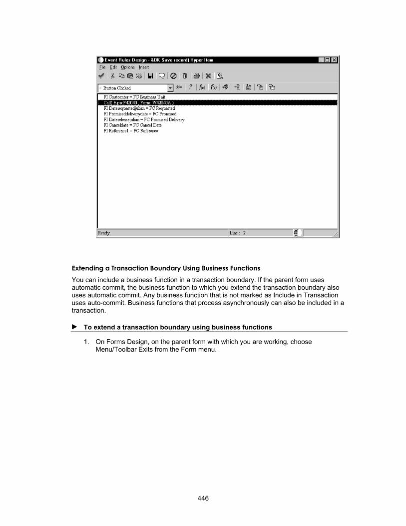
Extending a Transaction Boundary Using Business Functions You can include a business function in a transaction boundary. If the parent form uses automatic commit, the business function to which you extend the transaction boundary also uses automatic commit. Any business function that is not marked as Include in Transaction uses auto-commit. Business functions that process asynchronously can also be included in a transaction.
► To extend a transaction boundary using business functions
1. On Forms Design, on the parent form with which you are working, choose Menu/Toolbar Exits from the Form menu.
446

2. Choose the OK row and click the Event Rules button.
3. From Event Rules Design, choose the Button Clicked event, and click the Business Functions button.
447

4. From Business Function Search, choose the business function that you want to include in the transaction boundary.
5. On Business Function, click the following Transaction Processing option:
• Include in Transaction
448

Business Functions marked for both Asynchronous and Include in Transaction are included in the transaction boundary.
Extending a Transaction Boundary Using Table I/O Transaction processing is available only for the Open Table operation in Table I/O. The opening of a table determines whether interaction with that table will be manual commit (part of a transaction) or automatic commit. Any Open Table operation not marked as Include in Transaction uses auto-commit.
► To extend a transaction boundary using table I/O
1. On Forms Design, on the parent form with which you are working, choose Menu/Toolbar Exits from the Form menu.
449
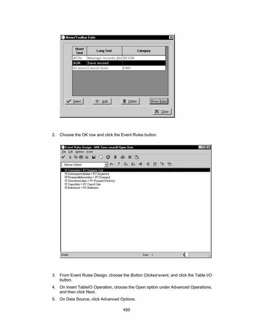
2. Choose the OK row and click the Event Rules button.
3. From Event Rules Design, choose the Button Clicked event, and click the Table I/O button.
4. On Insert TableIO Operation, choose the Open option under Advanced Operations, and then click Next.
5. On Data Source, click Advanced Options.
450

6. On Advanced Options, choose the Include in Transaction option, and then click OK.
7. On Data Source, click Finish.
• The Open operation appears in your event rules.
Refer to System Functions in the Online APIs for more information about using specific system functions.
Defining Transaction Processing for a Report
In addition to interactive transaction processing, OneWorld also provides transaction processing for reports and batch processes. To enable transaction processing for a batch process, click the Advanced tab for report properties and choose Transaction Processing.
451

Then, use the Transaction Processing system functions to define the beginning and end of your transactions. You can also extend your transaction boundaries to include business functions and table I/O. Refer to the Online APIs for more information about these system functions.
Setting the jde.ini for Transaction Processing and Lock Manager
You must modify the enterprise server and workstation jde.ini files to enable transaction processing.
For each OneWorld workstation, you must enable transaction processing by changing settings in the workstation jde.ini file. You should make these changes on the deployment server to the resident jde.ini file that is delivered to workstations through package deployment, and then deploy a package with the changed jde.ini file.
Understanding Concurrent Release Support
Prior to release B73.3, transaction processing was primarily controlled by settings in the [TP MONITOR ENVIRONMENT] section of the jde.ini. On the server, this section contains nine settings. On the workstation, this section contains seven settings.
For release B73.3, the [TP MONITOR ENVIRONMENT] section has been removed from the jde.ini and replaced with the [LOCK MANAGER] section. This new section contains three settings in both the server and client jde.ini files.
Settings that used to be in the [TP MONITOR ENVIRONMENT] section were removed because they were either obsolete or assigned an internal default value.
452
The following list provides the reasons that the settings in the [TP MONITOR ENVIRONMENT] section were eliminated for release B73.3:
Setting Reason for eliminating
Status Obsolete. As of release B732.2, the TP monitor is always set to ON.
LogPath Assigned the base directory from the jde.ini file.
LogStatements Obsolete. Statements are always logged.
LogBufferSize An internal default (1 MB) is used.
DisplayServerErrorMsg Obsolete. The client always displays server error messages.
This value is provided by JDENET settings.
ServerRetryInterval An internal default interval is used.
RegistryCleanupInterval An internal default interval is used.
RegistryRecordLifeSpan An internal default span is used.
ServerTimeout
During a transition period, both sections will be supported concurrently. The following three scenarios are possible during this transition period:
• The [LOCK MANAGER] section does not exist. In this scenario, OneWorld checks for settings in the [TP MONITOR ENVIRONMENT] section.
• Both [LOCK MANAGER] and [TP MONITOR ENVIRONMENT] sections exist. In this scenario, OneWorld uses the settings in the [LOCK MANAGER] section.
• Neither section exists. In this scenario, transaction processing cannot be started and a failure occurs.
Understanding Transaction Processing Logging
The commit coordinator acts in two phases. In the first phase, it instructs the Log Manager to flush the logs for each data source to hard disk for a permanent backup storage. The logs contain every database operation that was carried out.
The first phase ensures that if any of the data sources fail to commit after the others have committed, all databases can be returned to a consistent state by referring to the contents of the logs. If all of the logs for each of the data sources are flushed successfully, then the second phase begins.
In the second phase, the coordinator instructs each of the data sources to commit its respective transaction. If any of the data sources fails to commit, a commit log report is generated from the logs that were generated in phase one (this is written to the directory specified in the LOGPATH in the jde.ini, which contains a list by data source of all the SQL statements that were part of the transaction). The commit log also contains the details about which data sources passed and which ones did not.
The log can help the database administrator to manually synchronize the data sources so that they are all in a consistent state. The commit log report is generated only when at least one data source fails to commit. If all data sources successfully commit, then no commit log report is generated, and all the logs from phase one are deleted by the Log Manager.
453
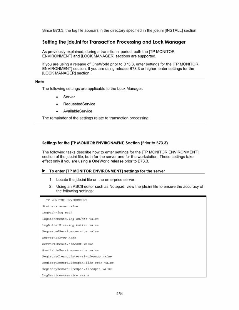
Since B73.3, the log file appears in the directory specified in the jde.ini [INSTALL] section.
As previously explained, during a transitional period, both the [TP MONITOR ENVIRONMENT] and [LOCK MANAGER] sections are supported.
Setting the jde.ini for Transaction Processing and Lock Manager
If you are using a release of OneWorld prior to B73.3, enter settings for the [TP MONITOR ENVIRONMENT] section. If you are using release B73.3 or higher, enter settings for the [LOCK MANAGER] section.
Note The following settings are applicable to the Lock Manager:
• Server
• RequestedService
• AvailableService
The remainder of the settings relate to transaction processing.
Settings for the [TP MONITOR ENVIRONMENT] Section (Prior to B73.3)
The following tasks describe how to enter settings for the [TP MONITOR ENVIRONMENT] section of the jde.ini file, both for the server and for the workstation. These settings take effect only if you are using a OneWorld release prior to B73.3.
► To enter [TP MONITOR ENVIRONMENT] settings for the server
1. Locate the jde.ini file on the enterprise server.
2. Using an ASCII editor such as Notepad, view the jde.ini file to ensure the accuracy of the following settings:
[TP MONITOR ENVIRONMENT]
Status=status value
LogPath=log path
LogStatements=log on/off value
LogBufferSize=log buffer value
RequestedService=service value
Server=server name
ServerTimeout=timeout value
AvailableService=service value
RegistryCleanupInterval=cleanup value
RegistryRecordLifeSpan=life span value
RegistryRecordLifeSpan=lifespan value
LogServices=service value
454

See the following table for explanations of the variables in the jde.ini file.
Setting Value
Status This setting indicates whether transaction processing is on or off. The transaction processing monitor typically should be on unless you are not using transaction processing in any of your applications, or if you want to temporarily disable transaction processing, such as for testing. Valid values are ON and OFF. As of B73.2, transaction processing cannot be turned off, so this value is ignored in versions B73.2 and higher.
LogPath This setting specifies the directory in which the transaction logs are placed. This path should correspond to the location of your jde.log and jdedebug.log.
For example, on a UNIX machine, the path might be:
/u10/owdevel/tc283984/b73.2
For more information about logging, see Understanding Transaction Processing Logging.
LogStatements This setting specifies whether the transaction monitor should keep a log of every operation performed within a transaction. Valid values are ON and OFF.
LogBufferSize This setting indicates the number of bytes set aside to hold the operations being logged in memory before they are copied to disk. This value is a OneWorld internal default value and should not be changed.
RequestedService This setting specifies the service that the client requests from the server. Valid values are:
Server This setting specifies the server that is hosting the TMS. For example, a server name might be intelnta.
ServerTimeout This setting indicates the timeout in seconds for all of the network operations. This value can be adjusted based on the network traffic. It is necessary for the workstation jde.ini file. It is also necessary for the server jde.ini file in case a batch job is running on the server. This value is a OneWorld internal default value and should not be changed.
AvailableService This setting indicates the service that this Transaction Management Server is offering. When the Transaction Manager on the workstation is initialized, it queries the TMS for this value. This is called TM-TMS handshaking. If this value is the same as the one that the workstation has in its jde.ini file, then that service will be invoked at the appropriate times when OneWorld is running. Valid values are:
RegistryCleanup Interval
This setting specifies the period after which all the expired records are deleted from the TMS record registry. This interval is specified in minutes. This value is a OneWorld internal default value and should not be changed.
• TS: Time stamp service is requested • NONE: No service is requested
• TS: Record Change Detector (Timestamp Service) • LM: Lock Management Service • ALL: Both TS and LM services • NONE: No service is available
455
RegistryRecordLife Span
This setting specifies the maximum period during which a record can exist in the TMS record registry. After this period, the record expires and is deleted. This life span is specified in minutes. This value is a OneWorld internal default value and should not be changed.
s This setting turns on the Trace Log for TMS, and supplements the Jde.log file. Valid values are:
1: Tracing for TMS is On 0: Tracing for TMS is OFF
The default value for this setting is 0. You should turn on tracing for TMS only after you have exhausted all other debugging methods.
► To enter [TP MONITOR ENVIRONMENT] settings for the workstation
1. Complete the steps to enable transaction processing on the server.
Note Be sure to enable transaction processing on the server before enabling it on the workstation. If you try to set up the workstation jde.ini file before you have set up the server jde.ini, you could be requesting a service on the server that is not yet available, which generates an error.
2. Locate the jde.ini file that will be sent to the workstation as part of a package
installation. This file is located on the OneWorld deployment server in the following release share path:
\\Bxxx\CLIENT\MISC\jde.ini
where xxx is the installed release level of OneWorld, such as B732.
3. Using an ASCII editor such as Notepad, view the jde.ini file to ensure accuracy of the following settings:
[TP MONITOR ENVIRONMENT]
Status=status value
LogPath=log path
LogStatements=log on/off value
LogBufferSize=log buffer value
RequestedService=service value
Server=server name
ServerTimeout=timeout value
See the following table for explanations of the variables in the jde.ini.
Setting Value
Status This setting indicates whether transaction processing is on or off. The transaction processing monitor typically should be on unless you are not using transaction processing in any of your applications, or if you want to temporarily disable transaction processing, such as for testing. Valid values are ON and OFF. As of B73.2, transaction processing cannot be turned off, so this value is ignored in versions B73.2 and higher.
456

LogPath This setting specifies the directory in which the transaction logs are placed. This path should correspond to the location of your jde.log and jdedebug.log.
For example, on a UNIX machine, the path might be:
/u10/owdevel/tc283984/b73.2
For more information about logging, see Understanding Transaction Processing Logging.
LogStatements This setting specifies whether the transaction monitor should keep a log of every operation performed within a transaction. Valid values are ON and OFF.
LogBufferSize This setting indicates the number of bytes that are reserved for the operations that are logged in memory before they are copied to disk. This value is a OneWorld internal default value and should not be changed.
RequestedService This setting specifies the service that the client requests from the server. Valid values are:
Server This setting specifies the server that is hosting the TMS. For example, a server name might be intelnta.
ServerTimeout This setting indicates the timeout in seconds for all of the network operations. This value can be adjusted based on the network traffic. It is necessary for the workstation jde.ini file. It is also necessary for the server jde.ini file in case a batch job is running on the server. This value is a OneWorld internal default value and should not be changed.
• TS: Time stamp service is requested • NONE: No service is requested
The last three lines of the section pertain to record change detection and must be set if you want the workstation to perform record is changed database locking.
Note Instead of deploying a package, you can manually copy the jde.ini file to all workstations.
Settings for the [LOCK MANAGER] Section (B73.3 and higher)
The following tasks describe how to enter settings for the [LOCK MANAGER] section of the jde.ini file, both for the server and for the workstation. These settings will be used even if you entered values for the [TP MONITOR ENVIRONMENT] section.
► To enter [LOCK MANAGER] settings for the server
1. Locate the jde.ini file on the enterprise server.
2. Using an ASCII editor such as Notepad, view the jde.ini file to ensure accuracy of the following settings:
[LOCK MANAGER]
Server=server name
AvailableService=available server service
RequestedService=client service request
457
See the following table for explanations of the variables.
Setting Value
Server This setting specifies the lock manager server to be used to process records. The value for this setting is the name of the server acting as the lock manager. For example, a server name might be intelnta.
If the client is used as a server, such as in cases where batch applications are running on the workstation, this setting must match the same entry in the [LOCK MANAGER] section of the jde.ini file on the workstation.
AvailableService
This setting applies only to servers.
RequestedService This setting indicates the type of service that the client requests from the server. Valid values are:
This setting indicates the available service of the server. Valid values are:
• TS: Time stamp service is available • NONE: No service is available
• TS: Time stamp service is requested • NONE: No service is requested
Caution Enable transaction processing on the server before you enable it on the workstation. If you try to set up the workstation jde.ini file before you set up the server jde.ini, you could be requesting a service on the server that is not yet available, which generates an error.
► To enter [LOCK MANAGER] settings for the workstation
1. Locate your workstation jde.ini file.
2. Using an ASCII editor such as Notepad, view the jde.ini file to ensure accuracy of the following settings:
[LOCK MANAGER]
Server=server name
RequestedService=client service request
See the following table for explanations of the variables.
Setting Value
Server This setting specifies the lock manager server to be used to process records. The value for this setting is the name of the server acting as the lock manager. For example, a server name might be intelnta.
If the client is used as a server, such as in cases where batch applications are running on the workstation, this setting must match the same entry in the [LOCK MANAGER] section of the jde.ini file on the workstation.
RequestedService This setting indicates the type of service that the client requests from the server. Valid values are:
• TS: Time stamp service is requested • NONE: No service is requested
458

Configuring jde.ini Files for Transaction Processing
[JDENET_KERNEL_DEF5]
dispatchDLLName=libtransmon.sl
dispatchDLLFunction=TM_DispatchTransactionManager
maxNumberOfProcesses=1
beginningMsgTypeRange=601
endingMsgTypeRange=650
newProcessThresholdRequests=0
[TP MONITOR ENVIRONMENT]
Status=OFF
LogPath=/u10/owdevel/tc283984/b73.1
LogStatements=NO
LogBufferSize=1000
AvailableService=TS
Server=hp9000b
ServerTimeout=60
RegistryCleanupInterval=1
RegistryRecordLifeSpan=1
AvailableService=TS
Server=hp9000b
ServerTimeout=60
RegistryCleanupInterval=1
RegistryRecordLifeSpan=1
[TP MONITOR ENVIRONMENT]
Status=OFF
LogPath=\b7\data
LogStatements=NO
LogBufferSize=1000
459
RequestedService=TS
Server=hp9000b
ServerTimeout=60
Record Locking
OneWorld does not implement any data-locking techniques. It relies on the native locking strategy of the vendor database management system. This process improves performance by reducing duplication of efforts.
In some specific situations, the vendor database does not automatically lock as needed. In these situations, you can use explicit instructions to OneWorld to control data-locking. For example, you can use record locking to ensure the integrity of the Next Numbers facility.
Understanding Record Locking
OneWorld data locking can be accomplished using one of the following methods:
• Optimistic Locking
You can use optimistic locking (sometimes referred to as record change detection) to prevent a user from updating a record if it has changed between the time the user inquired on the record and when he or she updates the record.
• Pessimistic Locking
You can use pessimistic locking to prevent attempts to update the same record at the same time. The record is locked before it is updated.
Optimistic Locking
You can turn on record change detection within the workstation jde.ini file. This type of database locking prevents a user from updating a record that changes during the time the user is inquiring about it. If the record has changed, the user must select the record again and then make the change. This feature is available for business functions, table I/O, and named event rules.
For example, suppose two users are working within the Address Book application The following table illustrates record change detection:
Time Action 10:00 User A selects Address Book record 1001 to inspect it.
10:05 User B selects Address Book record 1001 to inspect it.
Both users now have Address Book record 1001 open.
10:10 User B updates a field in Address Book record 1001 and clicks OK.
OneWorld updates Address Book record 1001 with information that User B entered.
10:15 User A updates a field in Address Book record 1001 and clicks OK.
OneWorld does not update Address Book record 1001, and the system displays a message
460

informing User A that the record has changed during the time that User A was viewing it. For User A to change the record, User A must reselect it and then perform the update.
When record change detection occurs, OneWorld displays a message that indicates that the record has been changed since it was retrieved.
Pessimistic Locking
Pessimistic locking is sometimes referred to as simply record locking. You can use record locking to prevent multiple users or applications from trying to update the same record at the same time. For example, suppose a user enters a transaction that uses Next Numbers. When the user clicks OK, the Next Number function selects the appropriate Next Number record, verifies that this number is not already in the transaction file, and then updates the Next Number record by incrementing the number. If another process tries to access the same Next Number record before the first process has successfully updated the record, the Next Number function waits until the record is unlocked, and then completes the second process.
Record locking in OneWorld is implemented by calling published JDEBase APIs. When you use record locking, you should consider the time required to select and update a record because the record is locked until the update is complete. Transaction processing uses a special set of locking APIs. A locked record might or might not be part of a transaction. Record locking APIs are independent of the transaction and its boundaries. They always lock, regardless of whether you are in manual or auto commit mode.
Records that are updated using record locking APIs (such as JDB_FetchForUpdate or JDB_UpdateCurrent) within a transaction boundary are locked from the time the record is selected for update until the commit or rollback occurs. Records within the transaction boundary that are updated without using record locking APIs are locked from the time of the update until the commit or rollback occurs. This is also true if you use a business function to define and activate transaction processing.
Using Pessimistic Record Locking Within a Transaction Boundary You might need to use record locking in conjunction with transaction processing. For example, if you want records to lock between the read and the update, you must use record locking.
Business Functions and Pessimistic Record Locking You might want to use record locking in a business function if the business function updates a table. The table being updated should have a high potential for record contention with another user or job. Remember that you should lock records for as short a time as possible. Ensure that the select or fetch for an update occurs as closely to the update as possible.
Currency
Enterprises that do business internationally have additional accounting needs and added complexity. This complexity arises from doing business in different currencies and having to follow different reporting and accounting requirements. Some fundamental requirements for an international enterprise include:
• Conversion of foreign currencies to the local currency
• Conversion of the different local currencies into one currency for reporting and comparisons
• Adhering to regulations defined in the countries of operation
461

• Revaluation of currencies due to changes in exchange rates
OneWorld Currency Implementation
OneWorld currency implementation includes the following features:
• Currency retrieval is done through database triggers and table event rules.
• Currency retrieval logic is handled in Business Functions.
• System APIs assist you in accessing cached tables.
Advantages
OneWorld allows you, the developer, to control currency retrieval. Allowing you, instead of the system, to control currency, provides greater flexibility and easier maintenance. Some of the advantages in allowing you to control currency are:
• Additional currency tables do not require changes to system modules. Only new business functions need to be added.
• Business logic is captured in business functions, rather than in a system module that assumes knowledge of business logic.
• Table event rules allow you to attach currency retrieval logic at the table object level.
• Table event rules are triggered by table events instead of application events.
• Any applications that use the table that has currency business functions attached to it receives the same logic, so you do not need to modify each application.
• No hard-coded logic is embedded in the runtime engine.
Working with Currency
Currency implementation is needed to adjust decimal placement on Math_Numeric currency fields according to a specified currency. When identified amounts are written to or retrieved from a database, or when they are used in calculations during processing, proper decimal placement is extremely important. Common applications of currency implementation include conversion of currency amounts and revaluation of currency due to changes in exchange rates.
Implementing currency involves the following steps:
• Perform currency setup.
• Create a business function that contains logic to retrieve currency information. These special currency business functions are known as currency triggers.
• Attach a currency trigger to the Currency Conversion event in Table Event Rules (TER).
• Design the TER functions through Event Rules Design. The system then converts the event rules to C and compiles them into a consolidated DLL through the Object Configuration Manager (OCM) Application.
• Modify applications if necessary.
The JDB APIs will then be responsible for calling the appropriate TER function when the Currency Conversion event is triggered.
462

Understanding the Build Triggers Option
The Build Triggers option performs the following steps:
• Converts event rules to C source code.
This creates the files OBNM.c and OBNM.hxx (where OBNM is the Object Name). The source file will contain one function per TER event.
For example, if you are working with table Accounts Payable Ledger table (F0411), the Build Triggers option creates a C source member called F0411.c. You can browse through the C code and ensure that all of the parameters are set up correctly. The system generates an error log if an error occurs during the ER-to-C conversion. The error table is called eF0411.log.
• Compiles the new functions and adds them to JDBTRIG.DLL. This is the Consolidated DLL that contains TER functions.
Understanding How Table Event Rules Work with Currency Processing
The Currency Conversion event runs if currency processing is ON.
Table triggers for currency run after the record is fetched and before the record is added to the database.
The following graphic illustrates the currency conversion process.
Currency Conversion
463

On FETCH: On ADD/UPDATE: 1. Application requests data 1. Application sends data
2. Is currency on? 2. Is currency on?
3. Yes, run currency trigger 3. Yes, run currency trigger
4. Currency Trigger calls TER, The TER 4. Currency Trigger calls TER
5. Return data to database and then application 5. Update database
• execute the business function • execute the business function • perform the business logic • perform the business logic • scrubs data accordingly • scrubs data accordingly
When passing Math_Numeric currency fields into a business function, the currency values in the respective data structure must be populated. Math_Numeric work fields that contain currency values also need the proper currency information.
You can copy currency information to controls (work fields or others) in event rules by using the system function Copy Currency Info. You can call the currency triggers from within an application's event rules or from another business function.
Setting Up Currency Conversion
If your business uses more than one currency, you must designate the method of currency conversion to use.
► To set up currency conversion
1. From the Multi-Currency Setup menu (G1141), choose Set Multi-Currency.
464
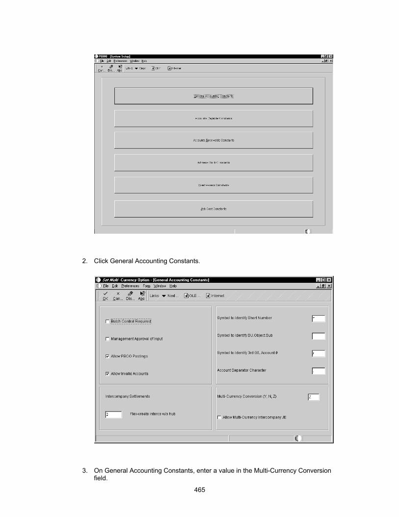
2. Click General Accounting Constants.
3. On General Accounting Constants, enter a value in the Multi-Currency Conversion field.
465

Valid values are:
N Do not use multicurrency accounting.
Y Turn on multicurrency and use multipliers to convert currency. The system multiplies the foreign amount by the exchange rate to calculate the domestic amount.
Z Turn multicurrency on and use divisors to convert currency. The system divides the foreign amount by the exchange rate to calculate the domestic amount.
The currency conversion flag is stored in Company Constant table (F0010) in the CRYR field for Company 00000.
You can set the Multi-Currency Conversion option to N so that currency conversion does not occur in JDB and the runtime engine.
Showing Currency-Sensitive Controls
When you design an application, you can decide whether to hide or show currency-sensitive controls, such as check boxes and radio buttons, at runtime.
► To show currency sensitive controls
1. On Forms Design, double-click the control that you want to appear on the form.
2. Click Options.
3. If you want to display currency fields, verify that the No Display if Currency is Off option is turned off.
When currency is off, currency-sensitive controls do not appear. If this option is turned off, currency fields are visible.
You must exit your current OneWorld session and re-enter in order to apply currency conversion changes.
Creating a Currency Conversion Trigger
If the tables contain currency fields, you must specify how many decimal places exist in each column. When the source or destination fields are currency fields and you have not created a currency trigger, problems might arise if the value is used in a calculation. If you do not create
466

a currency conversion trigger, the system has no way to determine where the decimal should be within a field.
► To create a currency conversion trigger
1. From Object Management Workbench, check out the table to which you want to attach event rules.
2. Ensure that the table is highlighted, and then click the Design button in the center column.
3. On Table Design, click the Design Tools tab and then click Start Table Trigger Design Aid.
4. On Event Rules Design, choose the Currency Conversion event and attach the currency trigger that you want to use.
5. Click the Business Functions button.
The Business Function Search form appears.
467

Use the QBE line to quickly search for selected business functions. You can use Category CUR or System Code 11 to find existing currency business functions. To read notes that describe the purpose of the business function, its parameters, and program requirements, click the Attachments button.
6. Choose the business function with which you want to work, and then click Select.
468

7. On Business Functions, attach the table columns to the business function structure, and then click OK.
The available objects that appear are for table column only.
8. On Event Rules Design, click Save, and then click OK.
9. On Table Design, click the Table Operations tab, and then click Generate Table.
10. Choose the data source for the table, and then click OK.
11. On Table Design, click the Design Tools tab, and then click Build Table Triggers.
The system creates the table event rule. The newly-created or modified table event rule functions are now called from the database APIs whenever the corresponding event occurs against the table.
469

Menu Design
Use the Menu Design program (P0082) to create, change, delete, copy, and filter menus and menu selections. Menu Design assists you in the following:
• Managing menus and menu selections
• Managing text overrides
• Defining runtime messages for menu selections
• Indicating the consequences of using particular menu selections
• Copying menu selections
Understanding Menus
A menu is the entry point for running reports and applications. The Menu Master table (F0082) stores the following information, which identifies and characterizes the menu:
• Identifying information (ID and related system code)
• Level of detail
• Menu classification
• Menu Text Override (F0083)
470

Menu Filtering
OneWorld automatically filters menus based on your user ID so that only menu selections that apply to your job appear on your workstation. This feature allows you to maintain one set of menus (one database) with hundreds of menu selections, but you see only those menus that apply to your job.
Menus are filtered so that the following selections do not appear:
• Menu selections that you or other users do not have authority to access - for example, Employee Information in Workforce Management.
• Menu selections that are country-specific to countries that do not apply to you. If the country code in your user profile matches the country code for that menu, then the selection appears. For example, menu selections that pertain only to Canadian users, such as Canadian tax-related selections, appear only to Canadian users.
• WorldVision menu selections that are not installed on your workstation. For example, if WorldVision (the J.D. Edwards AS/400 product) is not installed on your workstation, that selection does not appear on the menu. You can distinguish a WorldVision menu selection from a OneWorld menu selection by reviewing the job to execute number. A WorldVision job to execute number begins with J, such as J3413.
Menu Design Tables
Menu Design stores information in the following tables:
Menu Master (F0082) Defines all menus, but not the menu selections.
Menu Selection (F00821)
Contains the type of selection to be executed, selection consequences, and version information.
Menu Text Override (F0083)
Contains menu selection descriptions.
Menu Path (F0084) Contains the menu selection icons.
Working with Menus
Menus are the entry point to J.D. Edwards applications and reports. To access an application or report from a menu, the application or report must be attached to a menu selection on the menu.
Defining a New Menu
You can define a menu to include selections that enable you to access the applications and reports that you need from one location.
► To define a new menu
1. On System Administration Tools (GH9011), choose Menu Design.
2. On Work With Menus, click Add.
471

3. On Menu Header Revisions, complete the following fields:
• Menu Identification
• Menu Title
• Product Code
• Menu Classification
• Level of Display
• Advanced & Technical Operations
• Setup Menu
Reviewing Selections for a Menu
You can review the selections included on a specific menu from the Work With Menus form or from the Menu Header Revisions form.
► To review selections for a menu
1. On System Administration Tools (GH9011), choose Menu Design.
2. On Work With Menus, locate and choose a menu that you want to review.
The Work With Menu Selections form appears, from which you can view and edit selections for a specific menu.
472

Printing a Menu Report
You can print a report that lists the menus. You can print menus only or menus and menu selections. To print a menu report, choose Menu Print from the Form menu.
Example: Print Menus Report
473

R0082P J.D. Edwards & Company 4/25/00 13:33:23 Print Menus Page - 1 ___Menu______________________Description_________________SY__LOD___Class_ DEMO APPLICATIONS 00 Sel # Description Job To Form Version Ctry Appl Run Time SC _______________________________________________________Execute__________Name________________________Ovrd__ Message 0 APPLICATIONS 1 1 Journal Entries P0911 ZJDE0001 3 2 General Journal Posting R09801 3 3 Company Numbers and Names P0010 3 4 Budget vs.Actual Comparison P09210 ZJDE0001 2 5 Account Ledger Inquiry P0911L 1 6 Original Budget Update P14102 ZJDE0001 3 7 Online Consolidations P09218 ZJDE0001 1 8 Manufacturing Variance Inquiry P3102 ZJDE0001 1 11 Bill of Material P3002 ZJDE0001 1 12 Routings P3003 ZJDE0001 1 13 Forecasting P3460 ZJDE0001 1 14 Customer Service P4210 ZJDE0001 1 15 Planners Workbench P3401 ZJDE0003 1 16 Schedulers Workbench P31225 ZJDE0001 1
474
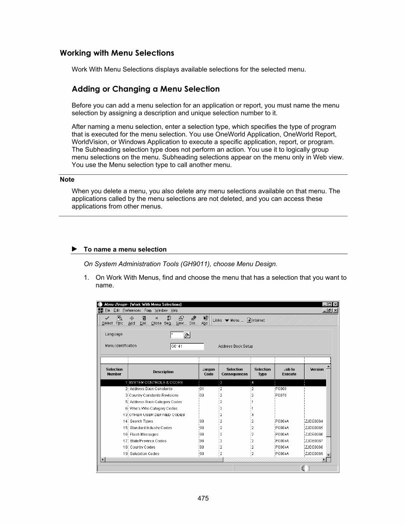
Working with Menu Selections
Work With Menu Selections displays available selections for the selected menu.
Adding or Changing a Menu Selection
Note
Before you can add a menu selection for an application or report, you must name the menu selection by assigning a description and unique selection number to it.
After naming a menu selection, enter a selection type, which specifies the type of program that is executed for the menu selection. You use OneWorld Application, OneWorld Report, WorldVision, or Windows Application to execute a specific application, report, or program. The Subheading selection type does not perform an action. You use it to logically group menu selections on the menu. Subheading selections appear on the menu only in Web view. You use the Menu selection type to call another menu.
When you delete a menu, you also delete any menu selections available on that menu. The applications called by the menu selections are not deleted, and you can access these applications from other menus.
► To name a menu selection
On System Administration Tools (GH9011), choose Menu Design.
1. On Work With Menus, find and choose the menu that has a selection that you want to name.
475

2. On Work With Menu Selections, click Add or choose an existing selection to change.
3. On Menu Selection Revisions, complete the following required fields:
• Selection Number
• Selection Description
• Selection Consequences
If you chose an existing selection to change, the Selection Number field is disabled.
4. Complete any of the following optional fields, if necessary:
• Jargon
• Country Code
If the base language is a double-byte language, a Search Description field appears below the Country Code field. Enter the single-byte search description to be used by Menu Word Search. Menu Word Search uses only single-byte search descriptions.
► To define the menu selection
On System Administration Tools (GH9011), choose Menu Design.
1. Find and choose the menu for which you want to define a menu selection.
2. On Work With Menu Selections, choose an existing selection to define.
3. On Menu Selection Revisions, choose one of the following selection types:
• OneWorld Application
476
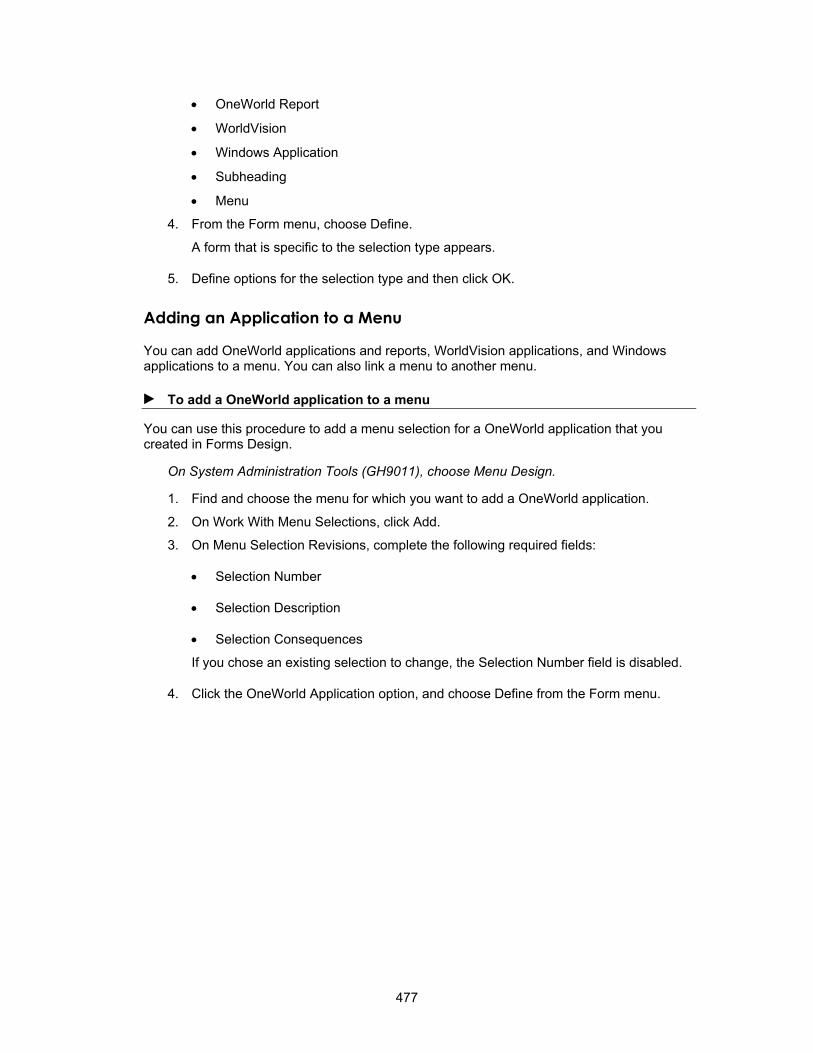
• OneWorld Report
• Subheading
• WorldVision
• Windows Application
• Menu
4. From the Form menu, choose Define.
A form that is specific to the selection type appears.
5. Define options for the selection type and then click OK.
Adding an Application to a Menu
You can add OneWorld applications and reports, WorldVision applications, and Windows applications to a menu. You can also link a menu to another menu.
► To add a OneWorld application to a menu
You can use this procedure to add a menu selection for a OneWorld application that you created in Forms Design.
On System Administration Tools (GH9011), choose Menu Design.
1. Find and choose the menu for which you want to add a OneWorld application.
2. On Work With Menu Selections, click Add.
3. On Menu Selection Revisions, complete the following required fields:
• Selection Number
• Selection Description
• Selection Consequences
If you chose an existing selection to change, the Selection Number field is disabled.
4. Click the OneWorld Application option, and choose Define from the Form menu.
477
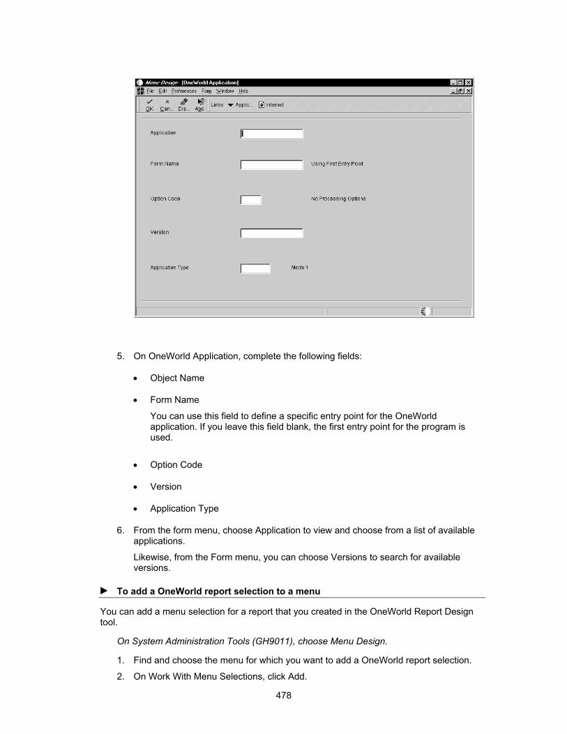
5. On OneWorld Application, complete the following fields:
• Object Name
• Form Name
You can use this field to define a specific entry point for the OneWorld application. If you leave this field blank, the first entry point for the program is used.
• Option Code
• Version
• Application Type
6. From the form menu, choose Application to view and choose from a list of available applications.
Likewise, from the Form menu, you can choose Versions to search for available versions.
► To add a OneWorld report selection to a menu
You can add a menu selection for a report that you created in the OneWorld Report Design tool.
On System Administration Tools (GH9011), choose Menu Design.
1. Find and choose the menu for which you want to add a OneWorld report selection.
2. On Work With Menu Selections, click Add.
478

3. On Menu Selection Revisions, complete the following required fields:
• Selection Number
• Selection Description
• Selection Consequences
If you chose an existing selection to change, the Selection Number field is disabled.
4. Click the OneWorld Report option, and choose Define from the Form menu.
5. On OneWorld Report, complete the following fields:
• Batch Application
• Versions
6. Select one of the following to specify the type of processing options that you want users to have:
• Blind Execution
• Values
• Version
• Data Selection
Use Form menu options to view and choose from a list of reports and versions.
► To add a WorldVision application to a menu
You can add a menu selection for a WorldVision application.
On System Administration Tools (GH9011), choose Menu Design.
1. Find and choose the menu for which you want to add a WorldVision selection.
2. On Work With Menu Selections, click Add.
3. On Menu Selection Revisions, complete the following required fields:
• Selection Number
• Selection Description
• Selection Consequences
If you chose an existing selection to change, the Selection Number field is disabled.
4. Click the WorldVision option, and choose Define from the Form menu.
479
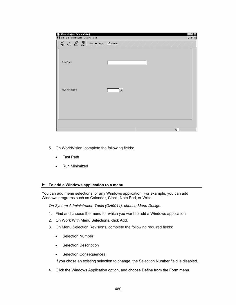
5. On WorldVision, complete the following fields:
• Fast Path
• Run Minimized
► To add a Windows application to a menu
You can add menu selections for any Windows application. For example, you can add Windows programs such as Calendar, Clock, Note Pad, or Write.
On System Administration Tools (GH9011), choose Menu Design.
1. Find and choose the menu for which you want to add a Windows application.
2. On Work With Menu Selections, click Add.
3. On Menu Selection Revisions, complete the following required fields:
• Selection Number
• Selection Description
• Selection Consequences
If you chose an existing selection to change, the Selection Number field is disabled.
4. Click the Windows Application option, and choose Define from the Form menu.
480
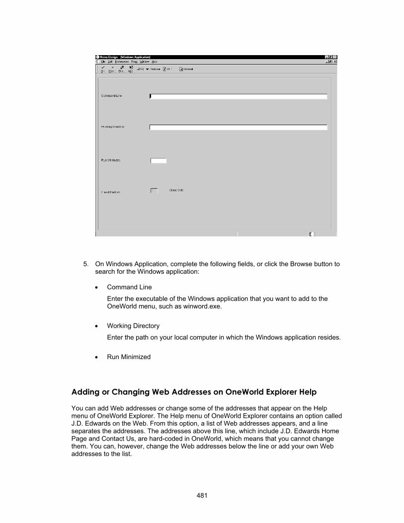
5. On Windows Application, complete the following fields, or click the Browse button to search for the Windows application:
• Command Line
Enter the executable of the Windows application that you want to add to the OneWorld menu, such as winword.exe.
• Working Directory
Enter the path on your local computer in which the Windows application resides.
• Run Minimized
Adding or Changing Web Addresses on OneWorld Explorer Help
You can add Web addresses or change some of the addresses that appear on the Help menu of OneWorld Explorer. The Help menu of OneWorld Explorer contains an option called J.D. Edwards on the Web. From this option, a list of Web addresses appears, and a line separates the addresses. The addresses above this line, which include J.D. Edwards Home Page and Contact Us, are hard-coded in OneWorld, which means that you cannot change them. You can, however, change the Web addresses below the line or add your own Web addresses to the list.
481
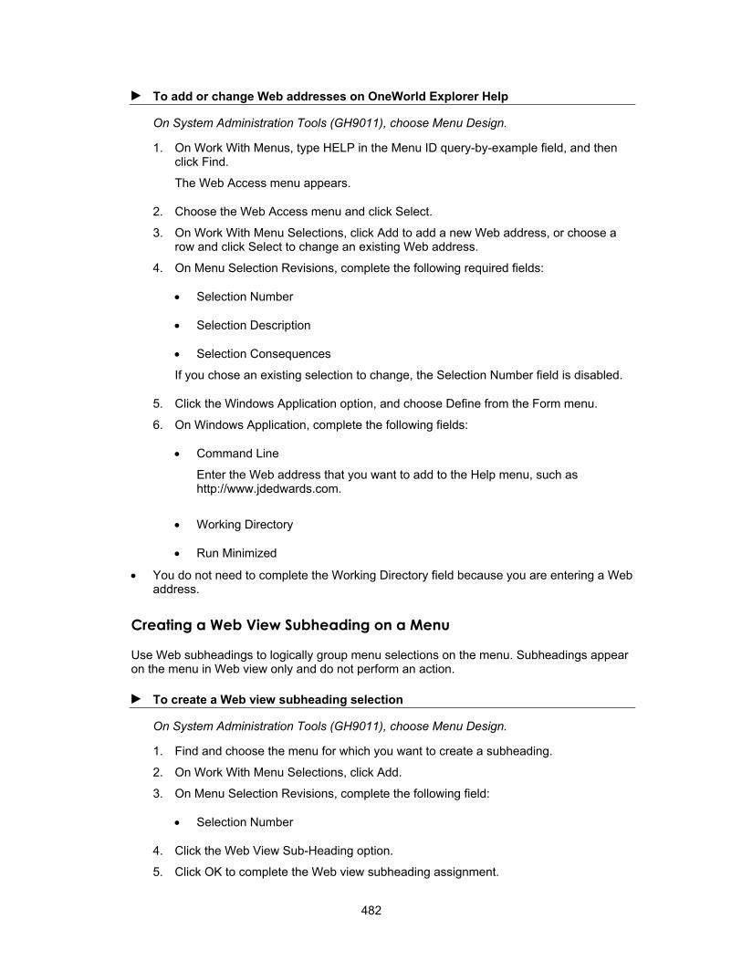
► To add or change Web addresses on OneWorld Explorer Help
On System Administration Tools (GH9011), choose Menu Design.
1. On Work With Menus, type HELP in the Menu ID query-by-example field, and then click Find.
The Web Access menu appears.
2. Choose the Web Access menu and click Select.
3. On Work With Menu Selections, click Add to add a new Web address, or choose a row and click Select to change an existing Web address.
4. On Menu Selection Revisions, complete the following required fields:
• Selection Number
• Selection Description
• Selection Consequences
If you chose an existing selection to change, the Selection Number field is disabled.
5. Click the Windows Application option, and choose Define from the Form menu.
6. On Windows Application, complete the following fields:
• Command Line
Enter the Web address that you want to add to the Help menu, such as http://www.jdedwards.com.
• Working Directory
• Run Minimized
• You do not need to complete the Working Directory field because you are entering a Web address.
Creating a Web View Subheading on a Menu
Use Web subheadings to logically group menu selections on the menu. Subheadings appear on the menu in Web view only and do not perform an action.
► To create a Web view subheading selection
On System Administration Tools (GH9011), choose Menu Design.
1. Find and choose the menu for which you want to create a subheading.
2. On Work With Menu Selections, click Add.
3. On Menu Selection Revisions, complete the following field:
• Selection Number
4. Click the Web View Sub-Heading option.
5. Click OK to complete the Web view subheading assignment.
482

Linking Menus
You can add a menu selection that displays another menu.
► To link another menu to a menu
On System Administration Tools (GH9011), Choose Menu Design.
1. Find and choose the menu for which you want to add a selection.
2. On Work With Menu Selections, click Add.
3. On Menu Selection Revisions, click the Menu option.
4. From the Form menu, choose Define.
5. On Menu Execution, complete the following fields or click the visual assists to search for menus:
• Menu to Execute
• Client Platform
483
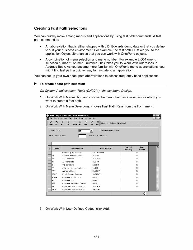
Creating Fast Path Selections
You can quickly move among menus and applications by using fast path commands. A fast path command is:
• An abbreviation that is either shipped with J.D. Edwards demo data or that you define to suit your business environment. For example, the fast path OL takes you to the application Object Librarian so that you can work with OneWorld objects.
• A combination of menu selection and menu number. For example 2/G01 (menu selection number 2 on menu number G01) takes you to Work With Addresses in Address Book. As you become more familiar with OneWorld menu abbreviations, you might find fast path a quicker way to navigate to an application.
You can set up your own a fast path abbreviations to access frequently-used applications.
► To create a fast path selection
On System Administration Tools (GH9011), choose Menu Design.
1. On Work With Menus, find and choose the menu that has a selection for which you want to create a fast path.
2. On Work With Menu Selections, choose Fast Path Revs from the Form menu.
3. On Work With User Defined Codes, click Add.
484
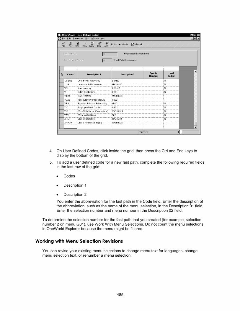
4. On User Defined Codes, click inside the grid, then press the Ctrl and End keys to display the bottom of the grid.
5. To add a user defined code for a new fast path, complete the following required fields in the last row of the grid:
• Codes
• Description 1
• Description 2
You enter the abbreviation for the fast path in the Code field. Enter the description of the abbreviation, such as the name of the menu selection, in the Description 01 field. Enter the selection number and menu number in the Description 02 field.
To determine the selection number for the fast path that you created (for example, selection number 2 on menu G01), use Work With Menu Selections. Do not count the menu selections in OneWorld Explorer because the menu might be filtered.
Working with Menu Selection Revisions
You can revise your existing menu selections to change menu text for languages, change menu selection text, or renumber a menu selection.
485

Copying a Menu Selection
You can copy an existing menu selection and attach it to another menu.
► To copy a menu selection
On System Administration Tools (GH9011), choose Menu Design (P0082).
1. On Work With Menus, find and choose the menu that has a selection that you want to copy.
2. On Work With Menu Selections, click Add.
3. On Menu Selection Revisions, enter the new selection number and choose Copy from the Form menu.
4. On Menu Selection Search, choose an existing menu selection.
The selection description, consequences, and type are inserted into the newly-added menu selection.
Changing Menu Text for Languages
You use title overrides to change the language and description of a menu selection.
► To change menu text for languages
On System Administration Tools (GH9011), choose Menu Design.
1. On Work With Menus, find and choose the menu for which you want to change menu text.
486

2. On Work With Menus, choose Header from the Row menu selection.
3. On Menu Header Revisions, from the Form menu, choose Title Overrides.
487
4. On Menu Text Overrides, enter the desired language code (such as S for Spanish) and text description (such as the Spanish description of the menu selection) in the following fields and then click OK:
• Language
• Menu Text
Changing Menu Selection Text
You use Text Overrides to change the text of a menu selection.
► To change menu selection text
On System Administration Tools (GH9011), choose Menu Design.
1. On Work With Menus, find and choose the menu for which you want to change the selection text.
2. On Work With Menu Selections, choose the menu selection that you want to change and click Select.
3. On Menu Selection Revisions, choose Text Overrides from the Form menu.
4. On Menu Text Overrides, complete the following fields and click OK:
• Language
• Menu Text
Changes in menu text do not appear until you close and reopen the changed menu. You can also choose Refresh from the View menu to update the menu text.
Renumbering a Menu Selection
You can renumber menu selections from both Work With Menu Selections and Menu Selection Revisions. You can edit each selection to change the sequence of selections on a menu. You cannot rearrange menu selections by clicking and dragging them.
► To renumber a menu selection
On System Administration Tools (GH9011), choose Menu Design.
1. On Work With Menus, find and choose the menu for which you want to change the selection number.
2. On Work With Menu Selections, choose the menu selection that you want to change and click Select.
3. On Menu Selection Revisions, choose Renumber from the Form menu.
488

4. Complete the following field, and click OK:
• New Selection Number
Tips of the Day
Tips of the day are sets of short, informational text that appear in a special form each time that the user launches an application or accesses a form. Tips of the day appear sequentially, so the user can browse through the tips. When the user closes the tip form, the system records where in the tip sequence the user is and displays the next tip when the user launches the object again.
J.D. Edwards provides tips of the day with many OneWorld applications. You can change these tip sets or create your own.
Working with Tips of the Day
In OneWorld, tips of the day are the glossary texts of data dictionary items. You create one data dictionary item for each tip. Since you can translate data dictionary glossaries, tips of the day can appear in different languages.
You can associate tips with an application, a form, or an application version. The tips appear in the order that you specify, and you can override a user's option to turn off the tip of the day feature for the tip set.
After you have associated tips with an object, you can rearrange the tip order, add new tips, or delete existing ones from the tip set.
489
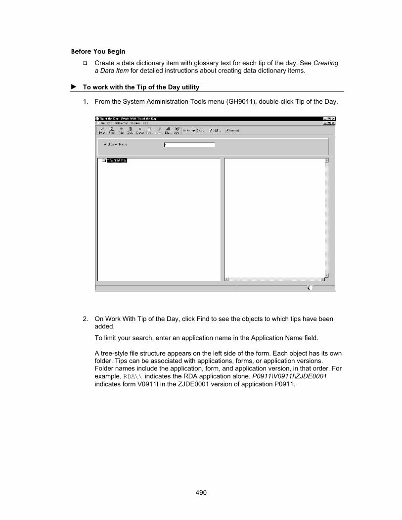
Before You Begin Create a data dictionary item with glossary text for each tip of the day. See Creating
a Data Item for detailed instructions about creating data dictionary items.
► To work with the Tip of the Day utility
1. From the System Administration Tools menu (GH9011), double-click Tip of the Day.
2. On Work With Tip of the Day, click Find to see the objects to which tips have been added.
To limit your search, enter an application name in the Application Name field.
A tree-style file structure appears on the left side of the form. Each object has its own folder. Tips can be associated with applications, forms, or application versions. Folder names include the application, form, and application version, in that order. For example, RDA\\ indicates the RDA application alone. P0911\V0911I\ZJDE0001 indicates form V0911I in the ZJDE0001 version of application P0911.
490
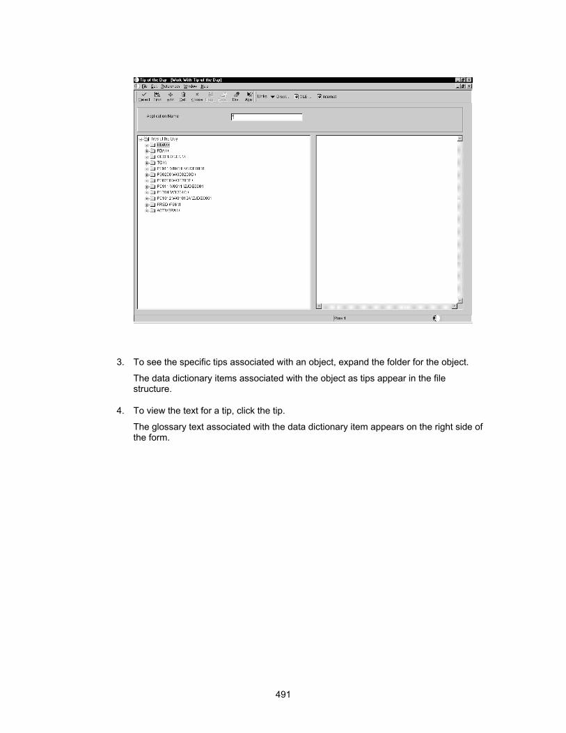
3. To see the specific tips associated with an object, expand the folder for the object.
The data dictionary items associated with the object as tips appear in the file structure.
4. To view the text for a tip, click the tip.
The glossary text associated with the data dictionary item appears on the right side of the form.
491
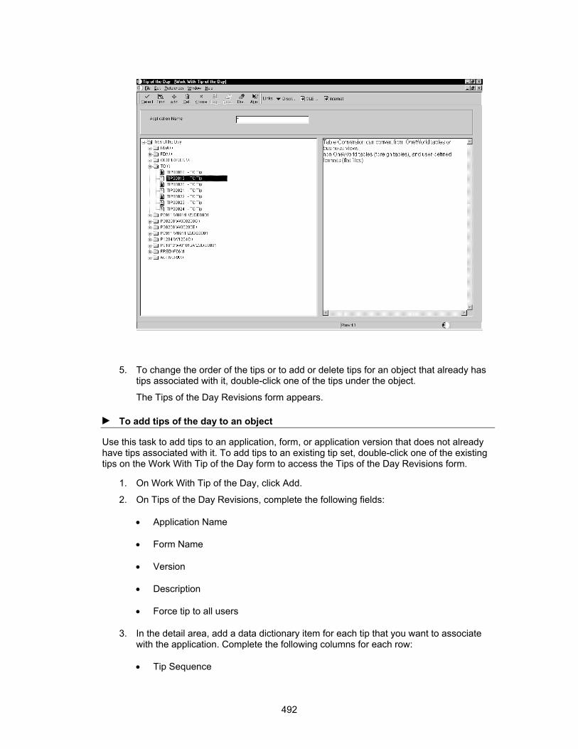
5. To change the order of the tips or to add or delete tips for an object that already has tips associated with it, double-click one of the tips under the object.
The Tips of the Day Revisions form appears.
► To add tips of the day to an object
Use this task to add tips to an application, form, or application version that does not already have tips associated with it. To add tips to an existing tip set, double-click one of the existing tips on the Work With Tip of the Day form to access the Tips of the Day Revisions form.
1. On Work With Tip of the Day, click Add.
2. On Tips of the Day Revisions, complete the following fields:
• Application Name
• Form Name
• Version
• Description
• Force tip to all users
3. In the detail area, add a data dictionary item for each tip that you want to associate with the application. Complete the following columns for each row:
• Tip Sequence
492

• Data Item
Note You cannot add a data dictionary item to the tip set if it does not have glossary text.
4. When you finish adding data dictionary items to the application, click OK.
493

Messaging
Use J.D. Edwards messaging facilities to get pertinent information to the end user in the most effective and user-friendly manner. When you design an application to use messaging, you must evaluate what information is necessary for a user to accomplish a task. You can deliver a message in real time, where the message is displayed on the status bar. The method you use to provide information to the user depends on the situation:
• Use an informational message sent to the Workflow Center if information needs to be conveyed and action requested.
• Use an interactive error message if there is an error during the entry of a record.
• Use an alert message if information is urgent and needs immediate attention.
• Use a batch error message if errors are detected while a report is running.
There are three parts to creating system-generated messages:
• The message itself.
Do you require a simple message or a text substitution message? Are all the text substitution pieces available?
• The logic.
Has certain criteria been met so that a message should be sent? This will usually be event rule logic.
• Is this an action message?
Does the message require action by the users? Are all the required parameters available at the time the message is to be sent?
Message Types
There are two main types of messages:
• Error and warning messages
• Information messages
Information messages can also be action messages that enable the user to connect from a current form to another form that will allow them to correct an error, or to evaluate information and then take action. To use action messaging you must be sure the parameters for the connecting form are available at runtime.
Within these message types you can use simple messages or text substitution messages. Text substitution messages allow you to use variable text substitution. Substitution values are inserted into the message for the appropriate variable at runtime. This gives the user a customized message unique to every instance of the message.
There are two types of text substitution messages:
• Error messages (glossary group E)
• Workflow messages (glossary group Y)
They are both created in the same manner.
494
Error Messages
Error messages are stored in the data dictionary. The data dictionary design tools can be found on menu GH951.
Workflow Messages
When designing an application to use messaging, you must evaluate what information needs to be used to decide whether a message needs to be created.
For example, if a voucher is created for $20,000 for capitalized equipment and the accounting department decides that the controller must be notified of any vouchers entered for greater than $10,000, the information needed to create a message from voucher entry would be "who is the controller," and "what are the keys to voucher entry." At this point, you need to determine what type of J.D. Edwards message would be appropriate and call that type of message within Event Rules. See Enterprise Workflow Management for more information about creating complete workflow processes using workflow messages.
Level Messages
Level messages are used to categorize error messages into the proper level break within a report. They are like a container for messages. Level messages can be thought of as titles, such as "Here are your batch errors" or "Here are the document errors," and so on. Level messages are used to separate every logical grouping of error messages. Messages that begin with "LM" are level messages. Level messages that belong to glossary group "Y," indicate that they are workflow messages.
Information Messages
Messages that are not level messages ("LM") but are in glossary group "Y" are considered informational messages (these may also include action messages). These messages supply pertinent information to the user and usually require action be taken.
Understanding Error Handling
Error handling is your first line of defense against your program being shut down by the operating system.
Event-Driven Model
Interactive messages display whenever a specific event occurs. This means that errors clear, set and display based on certain events. When an error occurs on an event, the event then runs again to clear the error.
For example, suppose the user types an incorrect value in a field. An error is set when the Control is Exited event is run (if you have logic on this event or a high level trigger is causing validation of the field). The user receives notification of the error through a visual cue (the field in error turns red). In addition, the status bar displays information about the error. To find out details about why the error occurred and how to correct it, the user can press the F8 function key. You can use the F7 function key to walk through the errors on a form if there are two or more errors.
495

The only way for the user to correct the error is to go into the field again, type in the correct value and leave the field. This causes the same Control is Exited event to be run again, which clears the error and sets it again in case an incorrect value is entered again. If the value typed in this time is correct, no error is set.
When is an Error Set?
When a user enters data in a form field or grid cell and tabs out, the runtime engine edits the value that was entered. If the edit fails, (such as a value is not found in the User Defined Code table, or an invalid date has been entered), an error is issued with the appropriate error code and the field is highlighted. The error message and message count are displayed on the status bar.
How Does the Application Know Which Field to Highlight?
When an error is issued, the handle is on the field. If the error is within a grid, then the offending grid cell coordinates (row and column) are identified. OneWorld stores this information in an Error_Ctrl_Key structure, along with the application form handle. At the time the error is displayed, the color of the control is changed and the error information is displayed from the error link list. If you use the system function Set Control Error or Set Grid Cell Error, you can specify the field or cell to highlight.
How Is an Event ID Used for Error Setting?
OneWorld applications are event-driven. Each keystroke or mouse click is considered an event. When a user enters a value in a control and tabs out of the field, the Leave Control event or Leave Column event validates that field. All errors are set using the event ID in the Error_Event_Key structure. This event ID is used to clear the errors that were set on this event when the event is reprocessed. For example, when the user enters an invalid address book number and tabs out of the field, an error is displayed. This error is set with the Control Handle, Event ID and Grid Cell Coordinate (if any). To clear this error, the user must enter a
496

valid address book number and tab out again. Validation is done and the error is cleared if no more errors are found on this control.
Error Setting
Errors are set:
• Automatically
• Manually
Automatic Error Setting
The runtime engine validates a field in the following instances:
• The item is a data dictionary item, for which an edit rule trigger has been defined in the data dictionary. In this case, the field for the data item is validated across all OneWorld applications. Data dictionary triggers can also be assigned or redefined using overrides within the Forms Design tool. However, in this case the trigger for the data item is specific to the the application where the override was defined.
• Validation is performed when the Control is Exited event, Column is Exited event, or OK Button Processing occurs. You can use validation to check for things such as invalid Data or invalid Dates.
Manual Error Setting
You can use either a system function or a business function API to set other error messages.
System Function You can use the following system functions for setting an error message:
• Set Edit Control Error
• Set Grid Cell Error
You can use Set Edit Control Error to set an error on a Form Control field through event rules. The following parameters must be passed in as system function arguments:
• Control (for example, the field that is in error)
• Error Code (a literal in this case means the error message, created through 3/GH951 or a variable)
You can use Set Grid Cell Error to set an error on a Grid Control field through event rules. You pass in the following parameters as system function arguments:
• Grid (does not receive any value)
• Row Number
• Column Number
• Error Code
System functions cannot use data items with text substitution.
Business Function API You can set an error message using a business function. This is used for manual error setting.
497

Use one of the following business function APIs to set an error message without text substitution:
• jdeErrorSet (lpBhvrCom, lpErrInfo, idItem, lpzError) sets errors through business functions.
• jdeSetGBRError (lpBhvrCom, lpVoid, (ID)0, "Error#")
Following is an example of an error message without text substitution:
{
jdeSetGBRError(lpBhvrCom,lpVoid,IDERRcRetainedEarningsLedger_3,”4524”);
idReturn = ER_ERROR;
}
The return code successful message has no influence on what happens next. It is used for information.
Use one of the following business function APIs to set an error message with text substitution:
• jdeErrorSet (lpBhvrCom, lpvoid, idItem, lpzError, lpDs) sets errors through business functions using substitution text. It always gets called
• jdeSetGBRErrorSubText
JdeSetGBRError and jdeSetGBRErrorSubText work the same except that jdeSetGBRErrorSubText has an additional parameter in which you pass the address of the data structure that holds the information you want substituted in.
Following is an example of the setup for a text substitution error message:
/**************************************************************************
* Declare structures
**************************************************************************/
DSDE0018 dsDE0018;.
.
.
/**************************************************************************
* Main Processing
**************************************************************************/
strncpy(dsDE0018.szAccountID, (const char *)(lpDS->szAccountID),
sizeof(dsDE0018.szAccountID));
.
.
.
if (idReturn != ER_SUCCESS)
{
jdeSetGBRErrorSubText(lpBhvrCom, lpVoid, IDERRszAccountID_1, ”044E”, &dsDE0018);
JDB_CloseTable(hRequestF0901);
JDB_FreeBhvr(hUser);
498
return ER_ERROR;
}
In this example, DSDE0018 is the data structure for the error messages and is declared in jdeapper.h. Jdeapper.h is where all of the data structures are declared for text substituted error messages used by J.D. Edwards. Non-J.D. Edwards substituted error messages should be defined in their own global declaration header file or in the function's header file that is using the structure. The line IDERRszAccountID_1 in this example contains the values to substitute.
A business function may call a validation routine (jdeddValidation), which when called may set an error if the field in question is invalid.
To use text substitution error messages in C business functions, you create an instance of a data structure in the global header file for every custom business function. If the error data structure exists, it should exist in jdeapperr.h
Resetting Errors
The system will reset errors on the OK button or on the Find button. This occurs on both manual and automatic errors.
Resetting Errors on the OK Button
The system resets errors when the OK button is clicked on a Header Detail form or a Headerless Detail form. The following actions occur:
1. Setup Error_Event_Key structure with event Button Clicked, the Control Handle is the OK button
2. Clear event errors on OK Button Clicked
3. Clear error due to the following events:
• Button Clicked Processing Done
• Add Record to DB - Before
• Add Record to DB - After
• Update Record to DB - Before
• Update Record to DB - After
• All Grid Recs Added to DB
• All Grid Recs Updated to DB
• Delete Record from DB - Before
• Delete Record from DB - After
• All Grid Recs Deleted from DB
• Delete Grid Rec Verify - Before
• Delete Grid Rec Verify - After
• Row is Exited
4. Stop processing if error still exists
499

5. Perform event rule on Button Clicked
6. ValidateAllData - this includes form controls
7. Stop processing if error occurred
8. Delete any rows that were removed from the grid
9. Perform event rule for Add or Update to Database Before or After
10. Perform grid changes (validate any unprocessed grid row)
11. Stop processing if error occurred
12. Perform event rule on After Button Clicked
13. Stop processing if error occurred
14. Otherwise, clear screen and exit
Note Do not try to validate and set errors on any grid control field for the Button Clicked event on the OK button. The Button Clicked event will not process all the grid rows.
Resetting Errors on the Find Button
The system resets errors on the Find button. It performs the following steps:
1. Setup Error_Event_Key structure with event Button Clicked
2. Clear event errors on OK/Select Button Clicked
3. Clear errors due to the following events:
• Button Clicked
• Last grid record has been read.
• Form Record is Fetched
• Grid Record is Fetched
• Confirm Delete - Before
• Confirm Delete - After
4. Perform event rule on Button Click
Multilevel Error Messaging for C Business Functions
When a business function calls another business function and the error is issued from the second business function, you must provide a mapping key array. Otherwise, errors will be set incorrectly.
When you use jdeCallObject (the standard API for calling other business functions from within a business function) for the second business function call, the sixth parameter is for
500

error mapping. Each business function has its own header and definition. You need to know why you are calling the second level business function. For example, suppose you are calling a second level business function to validate the company number. You must have the company number ID in the first business function header so you can find out the company number ID in the second business function.
► To create multi-level error messaging
1. Open the header file for the called business function and determine the maximum number of possible mapping fields.
Calling Function's Header File Called Function's Header File
#define IDERRszComputerid_1 1L #define IDERRcHeader_1 1L
#define IDERRszCompany_2 2L #define IDERRcEvent_2 2L
#define IDERRszDate_3 3L #define IDERRDetail_3 3L
#define IDERRszValue_4 4L #define IDERRCompany_4 4L
#define IDEERszPoint_5 5L #define IDERRDateOpen_5 5L
2. Create an Error map section in the C file for the calling business function.
In the following example of an active error message, you need to map one field (IDERRCompany_4).
/***************************************************
* Business Function: B1234
*
*
* Parameters:
* LPBHVRCOM
* LPVOID
* LPDS1234
**************************************************/
/***************************************************
* Error Mapping Section
*
* Map to function ”ValidateCompanyNumber”
* #define N1234 1
***************************************************/
The number 1234 is the data structure number of the called business function. The number 1 is the number of mapped fields.
Before each #define statement, include a comment that refers to the business function name for which this number will be used.
501

In the variable section, create a cm_xxx map array for each function that needs to return errors.
For example:
/**************************************************
* Variable declarations
**************************************************/
CALLMAP cm_1234[N1234]={{IDERRCompany_2,IDERRCompany_4}};
The array is mapped from IDERRCompany_2 to IDERRCompany_4.
The function call to jdeCallObject is:
idReturn = jdeCallObjdect(“ValidateCompanyNumber”, ValidateCompanyNumber, lpBhvrCom,lpVoid, &ds1234, cm_1234, N1234, (char *)NULL, (char *)NULL, (int)0);
The business function sets the error on the ID field.
Working with Error Messages
OneWorld displays messages automatically based on certain events. For example, you can display an error message whenever an invalid value has been entered into a field.
OneWorld uses the data dictionary glossary to display messages. The message is contained within the glossary portion of a data item. By leveraging the existing framework of the data dictionary, you do not have to create a messaging system from scratch.
Locating an Existing Error Message
You should use an existing message if possible instead of creating a new one. Use Work with Glossary Items to locate an existing message. You can narrow your search by using glossary group types and descriptions similar to the error you want.
► To locate an existing error message
1. On Work with Data Dictionary Items, choose Glossary Data Item from the Form menu.
502

2. On Work with Glossary Items, choose the message that you want to use.
503
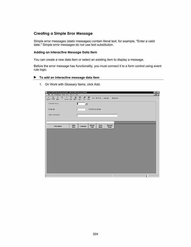
Creating a Simple Error Message
Simple error messages (static messages) contain literal text, for example, "Enter a valid date." Simple error messages do not use text substitution.
Adding an Interactive Message Data Item
You can create a new data item or select an existing item to display a message.
Before the error message has functionality, you must connect it to a form control using event rule logic.
► To add an interactive message data item
1. On Work with Glossary Items, click Add.
504

2. On Glossary Items, click the Item Specifications tab, and then complete the following fields:
• Glossary Group
• Product Code
• Description
• Error Level
Creating a Text Substitution Error Message
A text substitution error message is an error message that allows variable text to be substituted directly into the glossary text for the error message. This allows you to display the same basic message with some values that vary.
For example, suppose a user enters an invalid search type in a field. The error message "Search type xx is not contained in the 00 ST table" appears. The xx in the message will be replaced by the search type the user entered.
If you want to use text substitution error messages in batch processes, you must create a business function to pass values to the data dictionary data structure. The event rule engine (set user error) will not pass values to the text substituted error message.
505

Adding an Interactive Message Data Item
You can create a new data item or select an existing item to display a message. This example creates an error message in the Data Dictionary for error ID 018A.
Before the error message has functionality, you must connect it using event rule logic.
► To add an interactive message data item
1. On Work with Data Dictionary Items, choose Glossary Data Item from the Form menu.
506
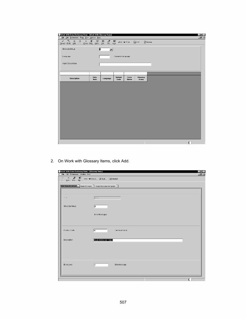
2. On Work with Glossary Items, click Add.
507

3. On Glossary Items, click the Item Specifications tab, and then complete the following fields:
• Glossary Group
• Product Code
• Description
• Error Level
When you type the description, use & followed by a number for each subset variable. In this example, the short description is &2 not found in User Defined Code &3 &4.
Now you are ready to define the glossary text to display at runtime.
Defining the Glossary Text for a Runtime Message
After you add an interactive message data item, you must add a glossary for that item.
► To define the glossary text for a runtime message
1. On Work with Glossary Items, click Glossary.
2. Type the text of your message. Use &x to assign variables in the text. These variables correspond to members in a data structure. Put a period with no blank spaces at the end of your glossary so that you do not have any repetition problems.
508

The order of the data structure is the index of the &x. If the structure contains four members, assign &1 to the first member, &2 to the second, and so on. For example:
Description = &1
UDC Value = &2
System = &3
Type = &4
3. When your text is complete, click OK.
OneWorld returns to the Glossary Header Revisions form.
Attaching a Data Structure Template to a Message
Each text substitution error message requires a corresponding data structure. If the data structure does not already exist, then you must create it. Make sure the members in your message match the members in your data structure. See Data Structures.
► To attach a data structure template to the message
1. On Glossary Items, click the Data Structure Template tab.
You can browse to locate an existing structure. However, if no existing structure meets your needs for the interactive message, you must create one.
2. To locate an existing structure, click the Browse button.
509

3. On Object Search, locate the data structure and click OK.
Attaching an Interactive Message Data Item
To make the error message display at runtime, you must attach a system function.
► To attach a message data item
1. On Event Rules Design, click the system function button.
510

2. Select the system function that you want to use.
3. Use available objects to complete the control value in Parameters.
511

4. Choose <Literal> for the Error Code Value in Parameters.
Use the number of the data dictionary item that contains the error message that you want to appear for the literal value.
512
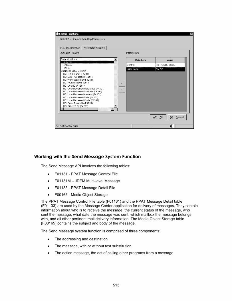
Working with the Send Message System Function
The Send Message API involves the following tables:
• F01131 - PPAT Message Control File
• F01131M – JDEM Multi-level Message
• F01133 - PPAT Message Detail File
• F00165 - Media Object Storage
The PPAT Message Control File table (F01131) and the PPAT Message Detail table (F01133) are used by the Message Center application for delivery of messages. They contain information about who is to receive the message, the current status of the message, who sent the message, what date the message was sent, which mailbox the message belongs with, and all other pertinent mail delivery information. The Media Object Storage table (F00165) contains the subject and body of the message.
The Send Message system function is comprised of three components:
• The addressing and destination
• The message, with or without text substitution
• The action message, the act of calling other programs from a message
513
The following table lists the parameters and their functions for the Send Message system function.
Parameter Description Typical Values Mandatory
Recipient The address book number of the person who is to receive the message.
Address Book Number - Data Dictionary item AN8
YES
Mailbox The Mailbox to which the message should be delivered, for example, "Personal in Basket"
The two-character field associated with a Mailbox, which is found in UDC 02/MB.
YES
*Subject The subject of the message. A brief description of the message, or Blank if a message template will be used.
NO
"None" should be selected if a message template is used.
*Text The main body of the message. The message that will be sent, or Blank if a message template will be used.
NO
"None" should be selected if a message template is used.
Active This indicates whether there should be a connection between the message being sent and another form.
When this item is selected the user will be prompted through the form interconnect process.
NO
DDMessage The Message Template from the data dictionary.
Any valid data dictionary item whose glossary can be used for a message.
NO
MessageKey This is a returned parameter that holds the key value for the message sent.
Data dictionary item, for example SERK.
NO
If the Subject and Text fields are used in conjunction with the DDMessage field, then the DDMessage (MessageTemplate) will be concatenated with the Subject and Text fields.
The following task illustrates how to use the send message system function.
► To use the send message system function
1. On Object Management Workbench, check out the table with which you want to work.
2. Ensure that the table is highlighted and then click the Design button in the center column.
3. On Table Design, click the Design Tools tab and then click Start Table Trigger Design Aid.
514

4. Click System Functions.
5. In the Recipient field, designate who is to receive the message.
515

This field typically uses an address book number. You can also use an e-mail address here.
6. Next, designate the Mailbox.
The mailbox indicates what type of message is being sent. Mailboxes are stored in the UDC table 02/MB. Mailboxes from UDC table 02/MB appear when focus is on the Mailbox field. The following form is an example of what might appear for mailboxes.
516

7. Click the data item called Active, and then choose Define Active Message to begin the form interconnection process.
The active message portion of the message works like form interconnections from event rules.
Defining an Active Message The following task illustrates the forms that appear as you define an active message.
► To define an active message
1. Double-click on Define Active Message.
517
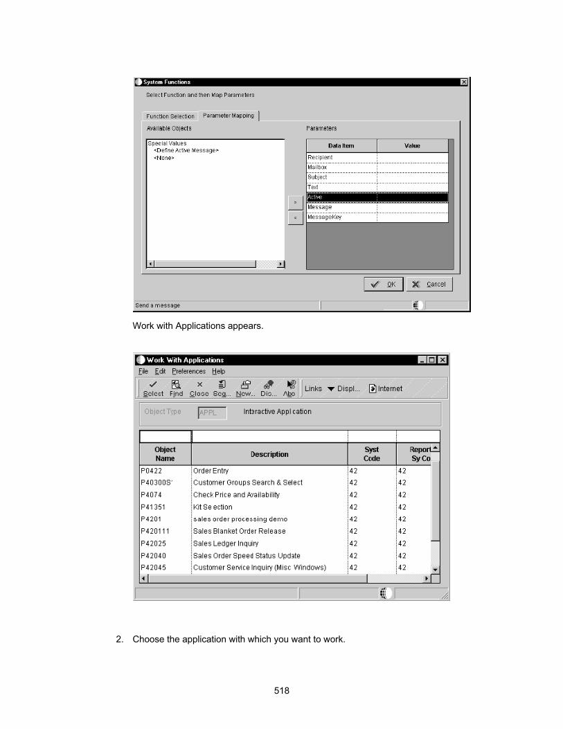
Work with Applications appears.
2. Choose the application with which you want to work.
518

3. Choose the form with which you want to work.
519
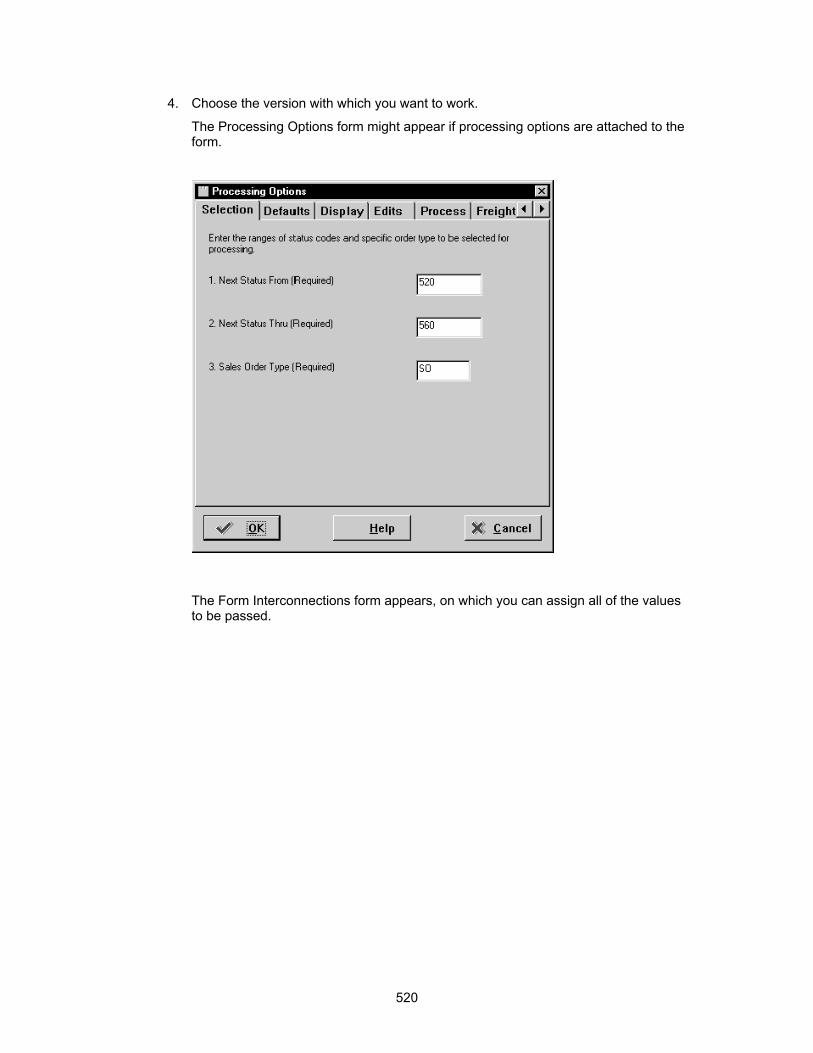
4. Choose the version with which you want to work.
The Processing Options form might appear if processing options are attached to the form.
The Form Interconnections form appears, on which you can assign all of the values to be passed.
520
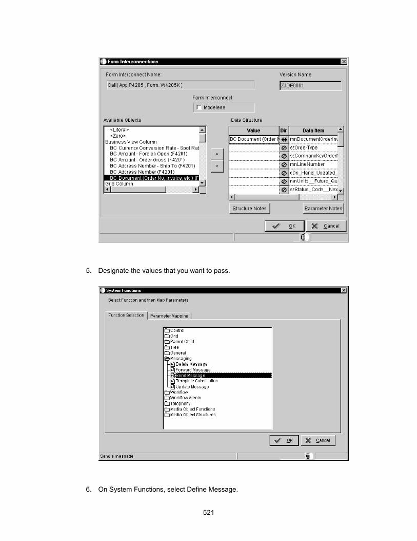
5. Designate the values that you want to pass.
6. On System Functions, select Define Message.
521

The system prompts you to select a message.
7. Enter the appropriate alias in the Dictionary Item field and click Find.
The substitution points are numbered &1, &2, and so on. The parameter numbers correspond to the substitution numbers. Substitution variables can appear in both the description and the glossary of the message.
522
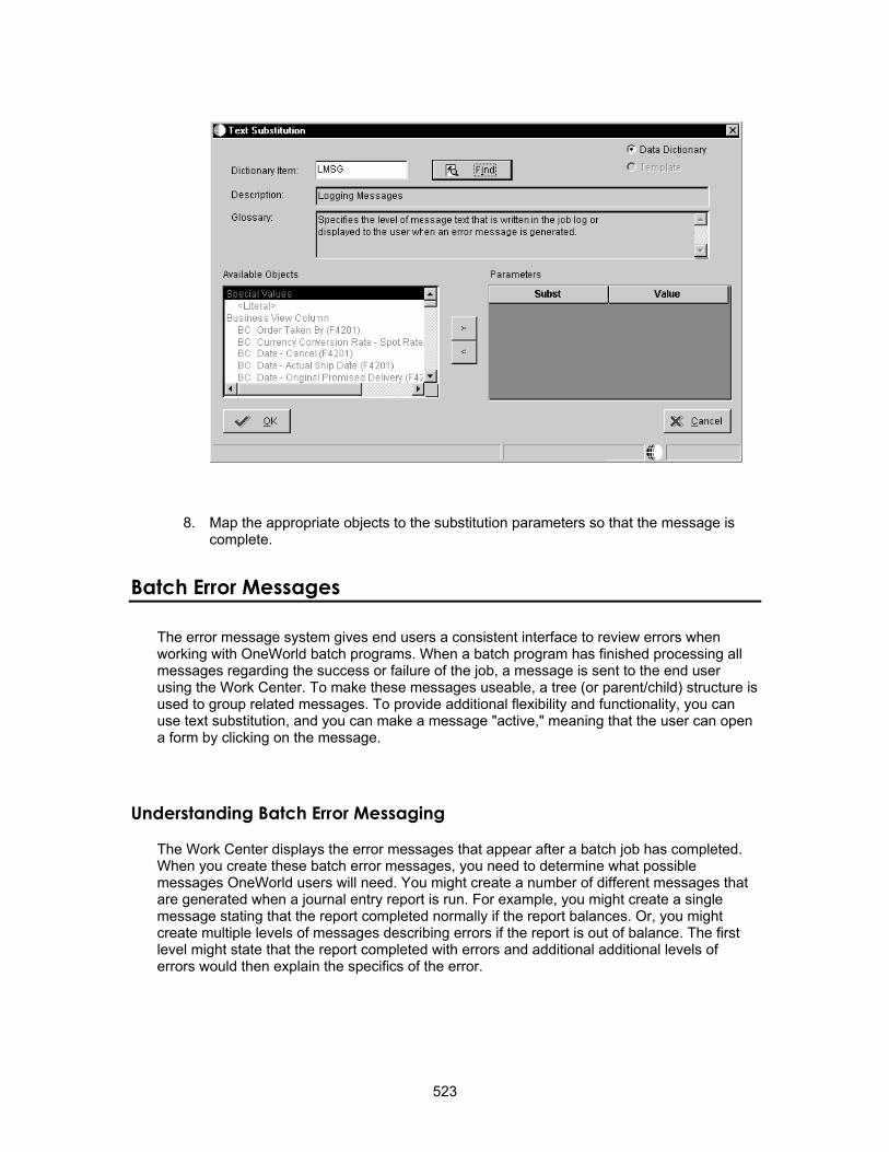
8. Map the appropriate objects to the substitution parameters so that the message is complete.
Batch Error Messages
The error message system gives end users a consistent interface to review errors when working with OneWorld batch programs. When a batch program has finished processing all messages regarding the success or failure of the job, a message is sent to the end user using the Work Center. To make these messages useable, a tree (or parent/child) structure is used to group related messages. To provide additional flexibility and functionality, you can use text substitution, and you can make a message "active," meaning that the user can open a form by clicking on the message.
Understanding Batch Error Messaging
The Work Center displays the error messages that appear after a batch job has completed. When you create these batch error messages, you need to determine what possible messages OneWorld users will need. You might create a number of different messages that are generated when a journal entry report is run. For example, you might create a single message stating that the report completed normally if the report balances. Or, you might create multiple levels of messages describing errors if the report is out of balance. The first level might state that the report completed with errors and additional additional levels of errors would then explain the specifics of the error.
523

Level-Break Messages
A level-break message is a message you can create that acts as a container for other error messages that are produced by the batch process. Level-break messages can be action messages, which contain a shortcut to an application and require action on the part of the user, or nonaction messages, which can be messages that instruct the user to review some information.
Understanding the role of a level-break message requires taking a closer look at how errors are created in batch jobs. Most errors are created by edits that occur at level breaks in the entire batch process. It is at these different level breaks that you want to group together any errors that may have occurred. The mechanism that groups these errors together is the level-break message. This implies that each reporting program that uses the Work Center application program interface (API) to manage errors will need to create one level-break message for each phase of level-break.
The following examples show the how messages might appear when an out-of-balance journal entry upload has completed.
See Also Understanding Level Breaks in the Enterprise Report Writing documentation for more
information about level breaks within sections.
First-Level Messages First-level messages appear when users open their personal in baskets. The plus symbol next to the message indicates that there are additional levels beneath it. First-level messages might show the name of the batch job, explain that it completed with errors, and instruct the user to review the detail of the errors.
524

Second-Level Messages Second-level messages appear when the user double-clicks the plus sign next to the first-level message. In this example, the second-level messages informs the user the batch number that needs to be reviewed.
Third-Level Messages Third-level messages appear when the user double-clicks the plus sign next to the second-level message. In this example, the third-level message instructs the user that the batch job completed with errors because it was out of balance, and then offers several solutions that will fix the problem.
525

Text Substitution Error Messages
Any error messages that you write need to be as informative to the user as possible. You can accomplish this through text substitution, which allows the system to embed variable text (such as dates, amounts, and so on) into a message that will be substituted at run time. You set up text substitution messages using the data dictionary, which helps ensure consistency of jargon and terms used. For example, the message "Voucher Batch 2453 contains errors," uses the value 2453 as a parameter to the message. This value is substituted at runtime, and the rest of the information from the message is kept in the data dictionary error glossary. This message is only the short description in the data dictionary. When you open the message, the complete data dictionary glossary with text substitution appears.
See Also Creating a Text Substitution Error Message in the Error Handling section of this guide
for procedures on creating interactive and batch message data items, defining the glossary text for a run time message, and creating a new data structure for the message.
Action Messages
After a user reviews errors and decides what needs to be fixed, the user usually need to go to a revision program to fix the errors. The Work Center allows you to set up level-break messages that will give the user the ability to fix the errors by calling the corresponding revision program directly from the Work Center. The term "action message" refers to the ability to call a OneWorld application and to pass the variables needed to that application. For example, the user would be able to automatically load the OneWorld Voucher Revision form
526

with the record in error by clicking a shortcut within the error message. It is up to you to call the appropriate application and pass the correct values to that application. Note that in some cases it may not make sense to call a particular program for a given level. Action messages are highlighted in the grid to differentiate them from nonaction messages.
Understanding How Level Break Messages Work
Level break and action messages are used to group together (or package) one or more errors.
All individual messages are level-break messages except for the final error messages. The Work Center API creates and manages Job Completed level-break messages, but you create all other messages. The level-break messages are not error messages. They are packaging or categorizing messages that you set up to communicate to the user information about in which batch, document, line, and so on the error occurred. You set these messages using the jdeSetGBRError or the jdeSetGBRErrorSubText function.
In this example, "Job R89004 ZJDE0001.c" and "Batch 3230 G in Error" are level break messages. "Job R89004 ZJDE0001.c" is a level one message that is automatically generated by the system and "Batch 3230 G in Error" is a level two message. "AA 20050606 3031" and "Intercompany Out of Balance" are actual error messages.
The level-break message consists of two distinct pieces. The first piece of a level-break message is the text for the message, and the second indicates whether the message will be an action message.
All level-break messages contain the text piece, but they might not all be enabled as action messages. The decision to enable the action message piece of the level-break message is left to the report designer.
527
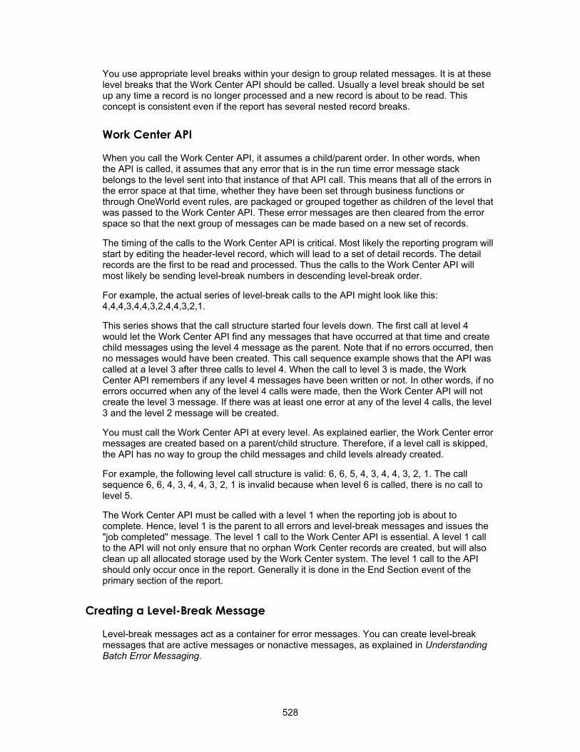
You use appropriate level breaks within your design to group related messages. It is at these level breaks that the Work Center API should be called. Usually a level break should be set up any time a record is no longer processed and a new record is about to be read. This concept is consistent even if the report has several nested record breaks.
Work Center API
When you call the Work Center API, it assumes a child/parent order. In other words, when the API is called, it assumes that any error that is in the run time error message stack belongs to the level sent into that instance of that API call. This means that all of the errors in the error space at that time, whether they have been set through business functions or through OneWorld event rules, are packaged or grouped together as children of the level that was passed to the Work Center API. These error messages are then cleared from the error space so that the next group of messages can be made based on a new set of records.
The timing of the calls to the Work Center API is critical. Most likely the reporting program will start by editing the header-level record, which will lead to a set of detail records. The detail records are the first to be read and processed. Thus the calls to the Work Center API will most likely be sending level-break numbers in descending level-break order.
For example, the actual series of level-break calls to the API might look like this: 4,4,4,3,4,4,3,2,4,4,3,2,1.
This series shows that the call structure started four levels down. The first call at level 4 would let the Work Center API find any messages that have occurred at that time and create child messages using the level 4 message as the parent. Note that if no errors occurred, then no messages would have been created. This call sequence example shows that the API was called at a level 3 after three calls to level 4. When the call to level 3 is made, the Work Center API remembers if any level 4 messages have been written or not. In other words, if no errors occurred when any of the level 4 calls were made, then the Work Center API will not create the level 3 message. If there was at least one error at any of the level 4 calls, the level 3 and the level 2 message will be created.
You must call the Work Center API at every level. As explained earlier, the Work Center error messages are created based on a parent/child structure. Therefore, if a level call is skipped, the API has no way to group the child messages and child levels already created.
For example, the following level call structure is valid: 6, 6, 5, 4, 3, 4, 4, 3, 2, 1. The call sequence 6, 6, 4, 3, 4, 4, 3, 2, 1 is invalid because when level 6 is called, there is no call to level 5.
The Work Center API must be called with a level 1 when the reporting job is about to complete. Hence, level 1 is the parent to all errors and level-break messages and issues the "job completed" message. The level 1 call to the Work Center API is essential. A level 1 call to the API will not only ensure that no orphan Work Center records are created, but will also clean up all allocated storage used by the Work Center system. The level 1 call to the API should only occur once in the report. Generally it is done in the End Section event of the primary section of the report.
Creating a Level-Break Message
Level-break messages act as a container for error messages. You can create level-break messages that are active messages or nonactive messages, as explained in Understanding Batch Error Messaging.
528

You create level-break messages by creating data dictionary items, error data structures, business function error structures, and business functions. For additional information about these topics, refer to the related sections in this guide.
Creating a Data Dictionary Item for a Level-Break Message
The data dictionary item is the text portion of the level-break message. Before you create a data dictionary item, you may want to review the level-break messages that have already been created. It is possible that the level-break message that you want to use already exists. This is the message you see in the work center.
► To create a data dictionary item for a level-break message
1. To search through the list of existing level-break messages, use Work with Data Dictionary Items.
For every level-break message created, there is a data dictionary item and at least one business function created to reference that item. To find out what level-break messages already exist, use query in the Object Management Workbench (OMW) to locate all business functions (BSFN) that start with the first three letters, BLM.
529

The BLM naming convention refers specifically to business functions for level-break messages that J.D. Edwards creates. J.D. Edwards recommends that you use the following criteria to name your own business functions for level-break messages: BLMxxyy, where xx refers to the system code you are using (between 50 and 55) and yy is a unique number. This unique number should be carried forward to other items. The maximum number of characters is eight.
Note Use the Description field to help you decide which existing messages might work in your report.
If you find several business functions for level-break messages that seem to fit your report design, write them down and verify the text on the data dictionary item itself, using the data dictionary to inquire on data items that begin with LM and are followed by the same numbers that followed the corresponding BLM function name.
530
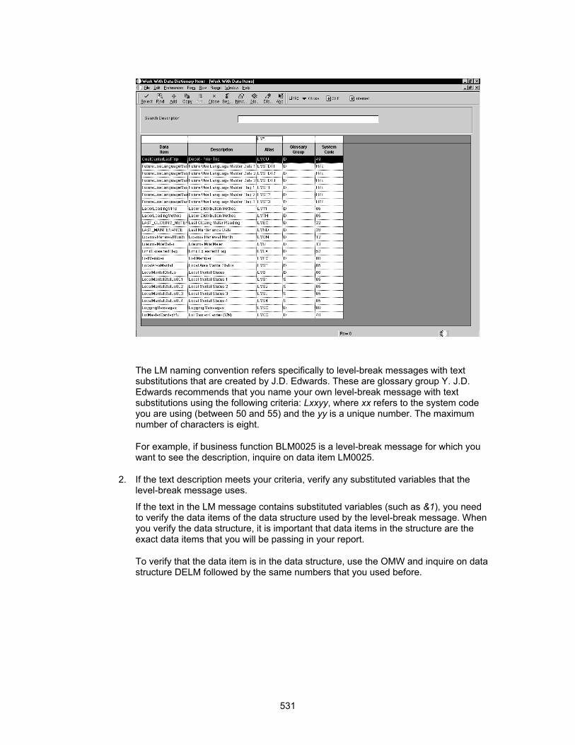
The LM naming convention refers specifically to level-break messages with text substitutions that are created by J.D. Edwards. These are glossary group Y. J.D. Edwards recommends that you name your own level-break message with text substitutions using the following criteria: Lxxyy, where xx refers to the system code you are using (between 50 and 55) and the yy is a unique number. The maximum number of characters is eight.
For example, if business function BLM0025 is a level-break message for which you want to see the description, inquire on data item LM0025.
2. If the text description meets your criteria, verify any substituted variables that the level-break message uses.
If the text in the LM message contains substituted variables (such as &1), you need to verify the data items of the data structure used by the level-break message. When you verify the data structure, it is important that data items in the structure are the exact data items that you will be passing in your report.
To verify that the data item is in the data structure, use the OMW and inquire on data structure DELM followed by the same numbers that you used before.
531

The DELM naming convention refers specifically to level-break message data structures that J.D. Edwards created. J.D. Edwards recommends that you name your own level-break messages using the following criteria: DELMxxyy, where xx refers to the system code you are using (between 50 and 55) and yy is a unique number. This unique number should be the same number that you used previously. The maximum number of characters is eight.
For example, DELM0025 would be the data structure created for the text substitution of level-break message LM0025. You might need to check out the structure to view individual fields.
Creating a Data Structure for the Data Dictionary Item
Each level-break message created requires a corresponding data structure to go with it. The data structure must be defined with the exact data items that will be substituted when the message is displayed. For example, a level-break message describing some error for Address Book Number would imply that the corresponding data structure would have data item AN8, the unique number that identifies an entry in the Address Book system. This restriction implies that many new data structures are going to be created.
To create the data structure, use OMW. The name should use the same unique number that was used when creating the Lxx data dictionary item. This number is to be appended to DELxx. For example, level-break message L55025 would use DEL55025 as the name of the data structure.
You will also need to create a typedef for this data structure. You include this typedef into the business function you create. The typedef converts the data structure to C so it can be used in the business function.
532

Refer to Data Structures for more information about data structures.
Creating a Level-Break Message Business Function Data Structure
You create business functions to deliver level-break messages. Each business function that you create needs to have several standard parameters in addition to the variables that are used for the text substitution and the variables needed for the message to be active. This means that you must create a second data structure to pass all of these variables.
The DLM naming convention refers specifically to J.D. Edwards-created business function data structures. J.D. Edwards recommends naming your own level-break messages using the following criteria: DLxxyy where xx refers to the system code you are using (between 50 and 55) and the yy is a unique number. This unique number should be the same number used previously. The maximum number of characters is eight.
For example, the J.D. Edwards-created level-break message LM0025 would use DLM0025 as the name of the business function data structure. You must have a business function for each level break message. This data structure is not to be confused with the data structure that was created for the data dictionary item in the previous procedure. The difference between the two is that the data structure for the business function is used to move data variables to the level-break function. The data structure used for the data dictionary item is used to store data that is mapped to the glossary for a particular data dictionary item.
533

When you create the data structure for the business function, include the following items:
• All data items used for the level-break text substitution message.
• All data items needed for the message to be active (that is, any variable or variables needed to load the form data structure for a given OneWorld application). Any data items that are used for the form interconnection only need to be renamed so that the letters FI_ appear after the Hungarian prefix. For example, jdFI_GlDate, or mnFI_Openamount. If you are not making the message active, you do not need to include these items.
• Add data item ev01 and change the variable name from OneWorldEventPoint01 to cIncludeInterconnect. This parameter is used as a flag to determine if the message is action. This parameter should be a common parameter to all level-break messages, even if the original intention of the level-break message is not to call a OneWorld application. This allows you to use level break messages in different applications, but not launch into application. You must have a 1 in the data structure value to launch an application.
• Add data item genlng and change the variable name from GenericLong to idGenlong. You use this parameter to control all Work Center messaging. It is not intended to be used for anything else other than as a work field for the system.
Creating a Level-Break Business Function
After you have created the DLxx data structure, you create the business function that processes the level-break errors and performs all of the mapping for the active message.
► To create a level-break business function
1. Create an object in the Object Management Workbench for the new business function.
The name of the business function is the unique number preceded by BLxx. For example, if you named the data dictionary item for the level-break message L55025,
534

you would name the business function BL55025. The J.D. Edwards naming convention is BLMxx.
2. Enter the name of the actual function on the Business Function Design form within Object Management Workbench.
When you name the function, the standard specifies that you start the function with the name SetLevel_xx, where xx refers to the system code. Append the function with other descriptive words to identify the purpose of the level-break message. For example, you might name the business function BLM0025 Set Level A/R Receipt Prepost Error.
3. In Business Function Design, attach the business function data structure to it by highlighting the row and then choosing Parameters from the Row menu.
This data structure should be the DLxx data structure that you created earlier.
The following sample of the shell source code shows which pieces need to be included and where you will be required to enter your own code.
4. Choose Form Create to generate a .h file.
5. Copy and paste the typedef for the business function into its header file.
6. Create a typedef for the text substitution data structure DExx. To create the typedef, you will need to create an inactive function line.
7. After you create the typedef, paste the data structure template into the Structure Definitions section of the business function header file.
8. Modify the source file for the level-break message by copying the source code of an existing BLMxxxx.C business function.
9. After you have copied the source into the new level-break business function, review the copied source and make the appropriate changes.
1Sample Source Code Highlights
You need to manually map fields from the business function's data structure to the dsTextData data structure. This is the data structure for text substitution in the level-break message. You also need to manually map fields from the business function's data structure to the dsFormData data structure. This is the data structure that is used for the active message.
In the "Variable declarations" section, you should have the following lines to declare the level-break message variables:
char szForm[11]; /* Name of form in application */
char szDDitem[11]; /* Data dictionary name of the level message */
char szDLLName[11]; /* Name of the application DLL */
char szDsTmp1[11]; /* Name of the text substitution data structure */
In the "Declare structures" section, you enter your own code for the appropriate type of level-break message. The following are examples from an existing business function:
DSDELM0002 dsTextData; /* Instance of text substitution structure */
FORMDSW0411Z1D dsFormData; /* Instance of form interconnect structure */
535
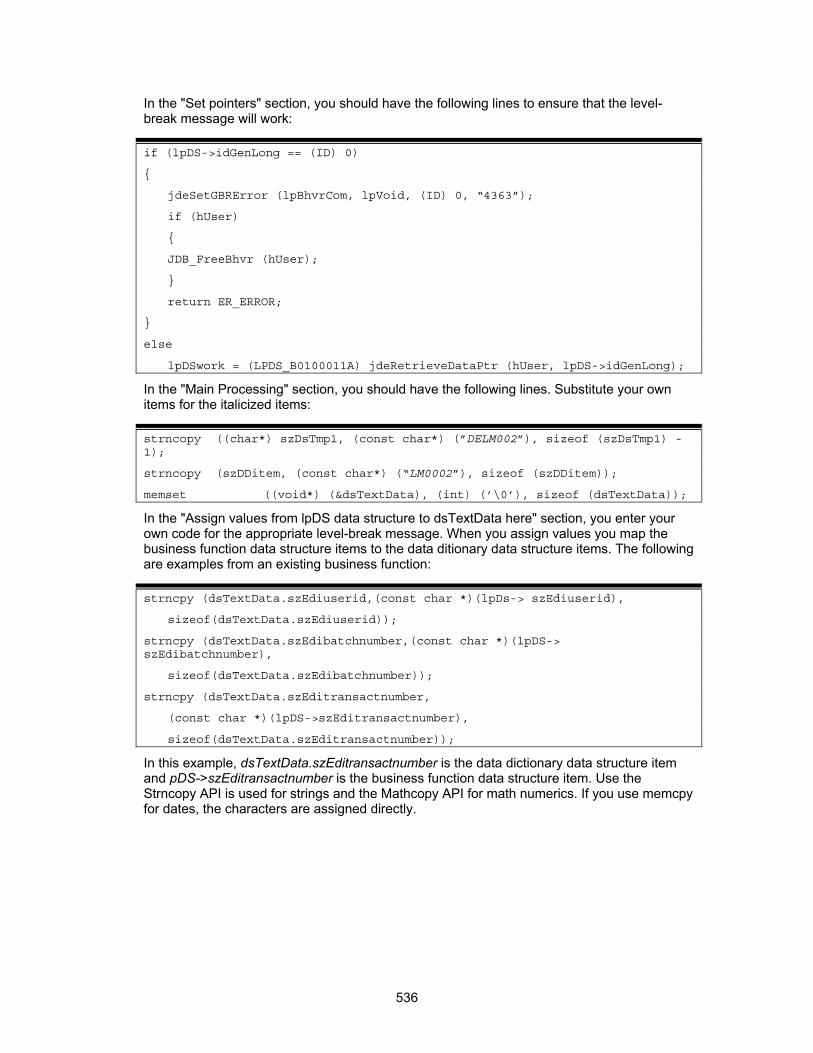
In the "Set pointers" section, you should have the following lines to ensure that the level-break message will work:
if (lpDS->idGenLong == (ID) 0)
{
jdeSetGBRError (lpBhvrCom, lpVoid, (ID) 0, “4363”);
if (hUser)
{
JDB_FreeBhvr (hUser);
}
return ER_ERROR;
}
else
lpDSwork = (LPDS_B0100011A) jdeRetrieveDataPtr (hUser, lpDS->idGenLong);
In the "Main Processing" section, you should have the following lines. Substitute your own items for the italicized items:
strncopy ((char*) szDsTmp1, (const char*) (”DELM002”), sizeof (szDsTmp1) -1);
strncopy (szDDitem, (const char*) (“LM0002”), sizeof (szDDitem));
memset ((void*) (&dsTextData), (int) (’\0’), sizeof (dsTextData));
In the "Assign values from lpDS data structure to dsTextData here" section, you enter your own code for the appropriate level-break message. When you assign values you map the business function data structure items to the data ditionary data structure items. The following are examples from an existing business function:
strncpy (dsTextData.szEdiuserid,(const char *)(lpDs-> szEdiuserid),
sizeof(dsTextData.szEdiuserid));
strncpy (dsTextData.szEdibatchnumber,(const char *)(lpDS-> szEdibatchnumber),
sizeof(dsTextData.szEdibatchnumber));
strncpy (dsTextData.szEditransactnumber,
(const char *)(lpDS->szEditransactnumber),
sizeof(dsTextData.szEditransactnumber));
In this example, dsTextData.szEditransactnumber is the data dictionary data structure item and pDS->szEditransactnumber is the business function data structure item. Use the Strncopy API is used for strings and the Mathcopy API for math numerics. If you use memcpy for dates, the characters are assigned directly.
536

In the "Assign values from lpDS data structure to dsTextData here" section, you should have the following lines to ensure that the level-break message will work:
JDBRS_GetDSTMPLSpecs (hUser, (char*) szDsTmpl, &lpDSwork->lpBlob->lpTSDSMPL);
if (lpDSwork->lpBlob->lpTSDSMPL != (LPDSTMPL)NULL)
{
lpDSwork->lpBlob->lpTSTEXT=(LPSTR)AllocBuildStrFromDstmplName((LPDSTMPL)
lpDSwork->lpBlob->lpTSDSMPL,(char*)szDsTmpl,
(LPVOID)&dsTextData);
strncpy (lpDSwork->lpBlob->szDDItem, (const char *)(szDDitem),
sizeof(lpDSwork->lpBlob->szDDItem));
}
if(lpDS->cIncludeInterconnect == ’1’)
In the "Form interconnect processing" section, you enter your own code for the appropriate level-break message. The following is an example from an existing business function. In the "Form interconnect processing" section, you should have the following lines to ensure that the level-break message will work.
strncpy (szDLLName, (const char*)(“P0411Z1”), sizeof (szDLLName));
memset ((void *)(&dsFormData), (int)(’\0’), sizeof(dsFormData));
memset ((void *)(szForm), (int)(’\0’), suzeif(szForm))
strncpy ((char *) szForm, (const char *)(“W0411Z1D”), sizeof (szForm) -1);
In the "Assign values from LpDS data structure to dsFormData" section, you enter your own code for the appropriate level-break message. The following is an example from an existing business function. This shows how you pass information from the data structure for the business function to the data structure for the form.
strncpy (dsFormData.EDUS,(const char *)(lpDS->szEdiuserid),
sizeof(dsFormData.EDUS));
strncpy (dsFormData.EDBT,(const char *)(lpDS-> szEdibatchnumber),
sizeof(dsFormData.EDBT));
strncpy (dsFormData.EDTN, (const char *)(lpDS->szEditransactnumber),
sizeof(dsFormData.EDTN));
ParseNumericString(&dsFormData.EDLN, ”1.0”);
dsFormData.EV01 = ’1’;
In the "Get the form data structure id from the SVRDTL table" section, you should have the following lines to ensure that the level-break message will work:
lptam = jdeTAMInit (FILENAME_SVRDTL);
strncpy ((char *) lpDSwork->lpBlob->szForm, (const char *)(szForm),size of (lpDswork->lpBlob->szForm) -1);
if (lptam != (LPTAM) NULL)
{
lpASVRdtl = TAMAllocFetchByKey (lptam, INDEX4_ASVRDTL, szForm, 1);
if (lpASVRdtl != (void *) NULL)
537
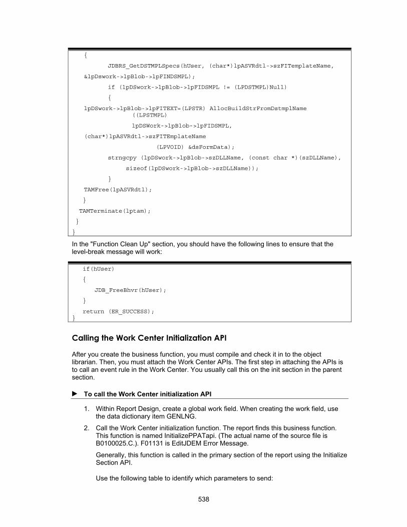
{
JDBRS_GetDSTMPLSpecs(hUser, (char*)lpASVRdtl->szFITemplateName,
&lpDswork->lpBlob->lpFINDSMPL);
if (lpDSwork->lpBlob->lpFIDSMPL != (LPDSTMPL)Null)
{
lpDSwork->lpBlob->lpFITEXT=(LPSTR) AllocBuildStrFromDstmplName ((LPSTMPL)
lpDSWork->lpBlob->lpFIDSMPL,
(char*)lpASVRdtl->szFITEmplateName
(LPVOID) &dsFormData);
strngcpy (lpDSwork->lpBlob->szDLLName, (const char *)(szDLLName),
sizeof(lpDSwork->lpBlob->szDLLName));
}
TAMFree(lpASVRdtl);
}
TAMTerminate(lptam);
}
}
In the "Function Clean Up" section, you should have the following lines to ensure that the level-break message will work:
if(hUser)
{
JDB_FreeBhvr(hUser);
}
return (ER_SUCCESS); }
Calling the Work Center Initialization API
After you create the business function, you must compile and check it in to the object librarian. Then, you must attach the Work Center APIs. The first step in attaching the APIs is to call an event rule in the Work Center. You usually call this on the init section in the parent section.
► To call the Work Center initialization API
1. Within Report Design, create a global work field. When creating the work field, use the data dictionary item GENLNG.
2. Call the Work Center initialization function. The report finds this business function. This function is named InitializePPATapi. (The actual name of the source file is B0100025.C.). F01131 is EditJDEM Error Message.
Generally, this function is called in the primary section of the report using the Initialize Section API.
Use the following table to identify which parameters to send:
538
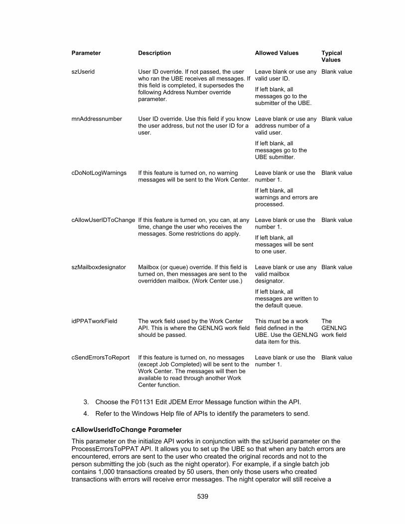
Parameter Description Allowed Values Typical Values
szUserid User ID override. If not passed, the user who ran the UBE receives all messages. If this field is completed, it supersedes the following Address Number override parameter.
Leave blank or use any valid user ID.
If left blank, all messages go to the submitter of the UBE.
Blank value
mnAddressnumber User ID override. Use this field if you know the user address, but not the user ID for a user.
Leave blank or use any address number of a valid user.
If left blank, all messages go to the UBE submitter.
Blank value
cDoNotLogWarnings If this feature is turned on, no warning messages will be sent to the Work Center.
Leave blank or use the number 1.
If left blank, all warnings and errors are processed.
Blank value
cAllowUserIDToChange If this feature is turned on, you can, at any time, change the user who receives the messages. Some restrictions do apply.
Leave blank or use the number 1.
If left blank, all messages will be sent to one user.
Blank value
The work field used by the Work Center API. This is where the GENLNG work field should be passed.
szMailboxdesignator Mailbox (or queue) override. If this field is turned on, then messages are sent to the overridden mailbox. (Work Center use.)
Leave blank or use any valid mailbox designator.
If left blank, all messages are written to the default queue.
Blank value
idPPATworkField This must be a work field defined in the UBE. Use the GENLNG data item for this.
The GENLNG work field
cSendErrorsToReport If this feature is turned on, no messages (except Job Completed) will be sent to the Work Center. The messages will then be available to read through another Work Center function.
Leave blank or use the number 1.
Blank value
3. Choose the F01131 Edit JDEM Error Message function within the API.
4. Refer to the Windows Help file of APIs to identify the parameters to send.
cAllowUserIdToChange Parameter This parameter on the initialize API works in conjunction with the szUserid parameter on the ProcessErrorsToPPAT API. It allows you to set up the UBE so that when any batch errors are encountered, errors are sent to the user who created the original records and not to the person submitting the job (such as the night operator). For example, if a single batch job contains 1,000 transactions created by 50 users, then only those users who created transactions with errors will receive error messages. The night operator will still receive a
539
message, but it would be a message such as "Job completed normally" or "Job completed normally with errors." Other users whose transactions were successful will not receive any error messages.
To set up this functionality, you need to enter a "1" in the cAllowUserIDToChange parameter when you initialize the batch error processing system. When you process the level 2 level-break message and then call the ProcessErrorstoPPAT API, you can still specify who will receive the messages by using the szUserid parameter. You can determine who should receive the message by looking at the transaction record.
Calling the Processing Work Center APIs
After the Work Center system has been initialized, you must determine the various level-break points within the report and call the Work Center system at each of these points to group the errors.
► To call the processing Work Center APIs
1. From Report Design, establish all of the appropriate level-breaks for the reporting batch job.
You need to analyze the events that will logically group all errors at a given event. This typically happen at events in which all editing has been completed for a group of records or immediately after all edits for an individual record have taken place.
2. For each level-break established, do the following:
• Call the business function for the level-break message at the appropriate level-break. The business function for the level-break message should relate to the type of error grouping that you want to occur at the particular level-break. For example, SetLevel_SFVoucher groups errors related at the voucher level-break. For reports, this business function is typically called in the Do Section. If the interconnect is blank, then it is not calling an action message.
Note The level that you send the API is never 1; it is sent only once, when you terminate the process.
540

• Call the Work Center error message function immediately after the call to the level-break message. This function is called ProcessErrorsToPPAT. B0100011.c processes batch errors to JDEM and makes repeated calls.
• Refer to the Windows Help file of APIs to identify the parameters to send.
Use the following table to identify which parameters to send. This is where you designate a level for the data dictionary level break message. Start your message with a level 2. The system automatically generates a level 1.
Parameter Description Allowed Values Typical Values
mnLeveloftotaling This parameter is the message level that you want the Work Center API to process.
Any valid number from 1-20.
Use the number 1 only when the UBE is almost finished. 1 writes the Job Completed message.
Numbers 1-20
idDataBaseWorkField Work field used by the Work Center API. This is where the GENLNG work field should be passed.
This must be a work field defined in the UBE. Use the GENLNG data item for this.
The GENLNG work field
Parameter Description Allowed Values Typical Values
cErrorPreProcessFlag This parameter allows the UBE to call the Work Center API at some event to flush the error space and to group any errors that are
Leave blank or use the letter P.
Blank value or Default
541

error space and to group any errors that are there by a level break message, which has yet to be sent.
If left blank, errors that are in the error space are grouped by the level message being sent in the first parameter.
Default
szUserid When the cAllowUserIDToChange option has been set in the initialization function, this parameter accepts the new user ID.
Leave blank or use any valid user ID.
If left blank, all messages are written to the last user ID used.
Blank value or Default
Terminating the Work Center Process
After all messages have been sent to the Work Center, you must terminate the Work Center process before the reporting job is finished.
When the batch program is about to terminate, call the Work Center error message function, ProcessErrorsToPPAT, one last time, sending it to level 1. The level 1 indicates the level of totaling is equal to 1 and that it is completed. This creates the job completed message and frees any work space that the Work Center API created.
Every report design that uses the Work Center API to process errors must use a level 1 to call the API at the end of processing. This should also be done by reporting jobs that are monitoring for any critical errors and that need to terminate early.
When the report has finished processing, it creates Work Center messages, which can then be read using the OneWorld Work Center application. Batch errors are processed to JDEM system. Messages created are sent to the user who ran the report unless you specify that the message be sent to another user or administrator.
If no errors are encountered, the API sends a message to the Work Center that indicates that the job completed successfully.
542
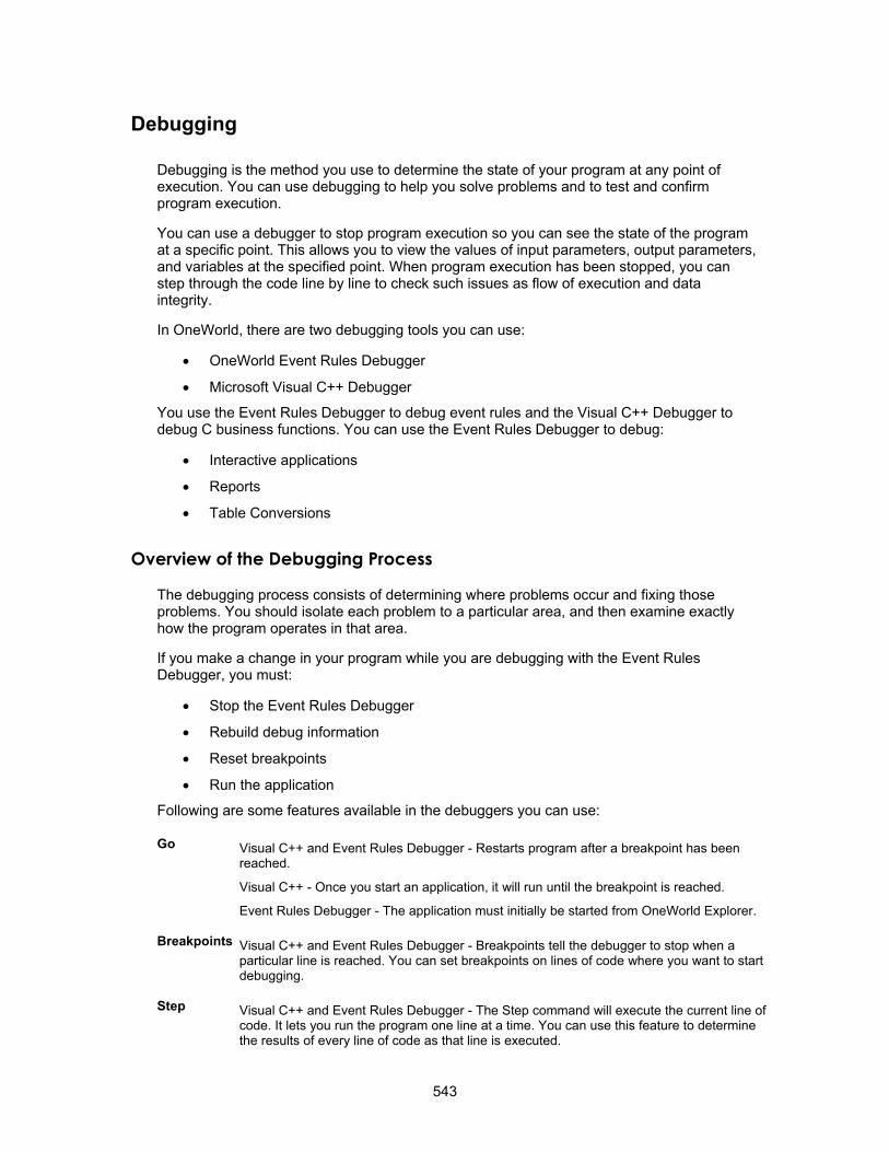
Debugging
Debugging is the method you use to determine the state of your program at any point of execution. You can use debugging to help you solve problems and to test and confirm program execution.
You can use a debugger to stop program execution so you can see the state of the program at a specific point. This allows you to view the values of input parameters, output parameters, and variables at the specified point. When program execution has been stopped, you can step through the code line by line to check such issues as flow of execution and data integrity.
In OneWorld, there are two debugging tools you can use:
• OneWorld Event Rules Debugger
• Microsoft Visual C++ Debugger
You use the Event Rules Debugger to debug event rules and the Visual C++ Debugger to debug C business functions. You can use the Event Rules Debugger to debug:
• Interactive applications
• Reports
• Table Conversions
Overview of the Debugging Process
The debugging process consists of determining where problems occur and fixing those problems. You should isolate each problem to a particular area, and then examine exactly how the program operates in that area.
If you make a change in your program while you are debugging with the Event Rules Debugger, you must:
• Stop the Event Rules Debugger
• Rebuild debug information
• Reset breakpoints
• Run the application
Following are some features available in the debuggers you can use:
Go Visual C++ and Event Rules Debugger - Restarts program after a breakpoint has been reached.
Visual C++ - Once you start an application, it will run until the breakpoint is reached.
Event Rules Debugger - The application must initially be started from OneWorld Explorer.
Breakpoints Visual C++ and Event Rules Debugger - Breakpoints tell the debugger to stop when a particular line is reached. You can set breakpoints on lines of code where you want to start debugging.
Step Visual C++ and Event Rules Debugger - The Step command will execute the current line of code. It lets you run the program one line at a time. You can use this feature to determine the results of every line of code as that line is executed.
543
Step Into Visual C++ an Event Rules Debugger - This is used when the current line of code contains a function call. The debugger will step into the function so that it can be debugged line by line. When the function is complete, the debugger returns to the next line of code after the function call in the calling routine. In OneWorld, the Step Into command can be used to debug a second application that is called from within a OneWorld calling application.
Skip Visual C++ and Event Rules Debugger - Skip is used to skip execution of a line of code. The line of code which is not executed will turn red.
Step Over Executes a single line of code. If the line of code is a function call, report interconnection, or form interconnection then that call will not be stepped into.
Stop This stops the debugging process.
If you stop the Event Rules Debugger, the application continues to run, as if the debugger had not been started.
In Visual C++ the debugging process stops and the running application is also terminated.
Watch Visual C++ and Event Rules Debugger - This lets you display the value of variables while the program is running. It also lets you inspect expressions, so you can see how a particular expression changes when variables change.
Interpretive and Compiled Code
OneWorld uses both interpretive and compiled code.
Interpretive code refers to code that is compiled as it runs. The translation from program instruction to machine instruction happens at runtime. Interpretive code lies within the application. Event rules scripting code used within Form Design and Report Design is interpretive. Interpretive code allows you to customize without going through a compile process every time you change something.
Compiled code is compiled and stored in an object file that may be called independently. The translation from program instruction to machine instruction happens at compile time. For example, table event rules, named event rules, and business functions are compiled. They are outside the application. They are also less subject to change. You can use Visual C++ to debug compiled code. The event rules scripting language can be translated into C, Java, or your current language of choice. The logic only needs to be interpreted one time. Interpretive code is more flexible.
Working with the Event Rules Debugger
The Event Rules Debugger provides the essential debugging tools (breakpoints, step commands, and variable inspection), you need to debug a OneWorld interactive or batch application. You can use the Event Rules Debugger to debug named event rules and table event rules. When the Event Rules Debugger builds debug information for an application, it includes named event rule and table event rule information for that application.
There are two main steps to set up and use the Event Rules Debugger:
• Running the Event Rules Debugger and setting breakpoints
• Running and debugging the application, report, or table conversion
If you want to save the debug information table but do not want the Debugger active during your work, you can deactivate debug information. You can activate the table at any time to continue debugging.
544

Understanding the Event Rules Debugger
The Event Rules Debugger is a standalone tools program that consists of five main controls:
• Object Browse window
• Event Rules windows
• Breakpoint Manager
• Variable Selection and Display window
• Search combo box
All windows except the event rule windows are dockable to any side of the main application. You can right-click on a window to dock it or to hide it. If you close the Debugger, it will retain your docking settings so they are the same the next time you run the Debugger.
Object Browse Window
The Object Browse window lists applications that have debug information built and that are available for debugging. You can drill down through the tree to a specific event and open an Event Rules window for that event.
Event Rules Window
The Event Rules window displays the event rules for one event. The event name and path are displayed in the title bar for each Event Rule window. You can right-click to toggle the title between its long and short versions. The Event Rules windows show which line in the event rules is currently being executed.
545

The left hand side of an Event Rule window displays icons that describe the state of a line in the event rules, including the following states:
• Breakpoint
• Disabled
• Current line of execution
Through the Event Rules window you can set and remove breakpoints, using any of the following methods:
• Double-click the line in event rules
• Choose a line and from the Debug menu choose Breakpoints
• Right-click a line and choose breakpoints from the menu that appears
• Choose a line and press F9
Variable Selection and Display Window
The Variable Selection and Display window consists of two views. The left view contains a tree control that lists the variable types as parent nodes and the current variables of that type as child nodes. The variables displayed are relative to the current Event Rule window. The right view is the variable display view. This view displays user selected variables and their current values. You can add a variable to the Variable Display view by double-clicking the desired variable in the Variables Tree.
You can change the value of variables while you are debugging an application. To change the value of a variable, double-click the variable in the Variable Display window. Change the value of the variable. The new value appears in the Variable Display window. If you enter an inappropriate value, for example if you change a numeric value to an alpha value, the new value is not set and the value is not changed.
There are three special values that are displayed for variables:
blank The value for the variable contains only blanks. This applies to string and character types only.
null The value for the variable is set to ASCII "\0".
unknown The value for the variable could not be obtained from the engine. This happens when the applications are not running or the variables are out of scope.
Note Variable inspection and modification is not available for debugging named event rules and table event rules.
Breakpoint Manager
Breakpoints tell the debugger where or when to break execution of a program. When the program is halted at a breakpoint, you can examine the state of your runtime structures, step through your event rules, and evaluate expressions using the Variable Watch window.
The Breakpoint Manager tracks which breakpoints are set and where they are located in an application. When you set a new breakpoint, an entry is made in the Breakpoint Manager. That entry contains the application name, form name, event name, and event rule line.
546

Right-click in Breakpoint Manager to perform the following operations:
• Delete breakpoints
• Delete all breakpoints
• Go to a breakpoint
You can also double-click on an entry in Breakpoint Manager to open the Event Rule window where the breakpoint is set.
Search Combo Box
You can use the Search combo box on the toolbar to search for event rule text. Enter the text you wish to search for in the Search combo box and either press Enter or F3. If the search text is found in your event rules text, the text is highlighted. If you press Enter or F3 again, the next occurrence of your search text is highlighted.
The search control allows for regular expression searches. A regular expression search uses special characters to match text, for example, ^If: will find every line that starts with "If" and If$: will find every line that ends with "If".
Following are the special characters you can use to perform more advanced searches.
^ The caret (^) indicates the beginning of the string. For example, the expression "^" matches an "A" only at the beginning of the string.
^
|
?
The parenthesis affects the order of pattern evaluation and serves as a tagged expression that you can use to replace a matched substring with another expression.
[ ]
The Event Rules Debugger allows you to debug interactive or batch applications.
The caret (^) immediately following the left bracket ( [ ) is used to exclude any remaining characters within brackets from matching the target string. For example, the expression "[^0-9]" indicates that the target character should not be a digit.
$ The dollar sign ($) matches the end of the string. For example, the expression "abc$" will match the substring "abc" only if it is at the end of the string.
The alternation character (|) allows the expression on either side of it to match the target string. For example, the expression "a|b" will match "a" as well as "b".
. The dot (.) matches any character.
* The asterisk (*) indicates that the character to the left of the asterisk in the expression should match 0 or more times.
+ The plus (+) is similar to the asterisk, except that there should be at least one match of the character to the left of the + sign in the expression.
The question mark (?) matches the character to its left 0 or 1 times.
()
Brackets ([ and ]) enclosing a set of characters indicate that any of the enclosed characters may match the target character.
Debugging an Application
547
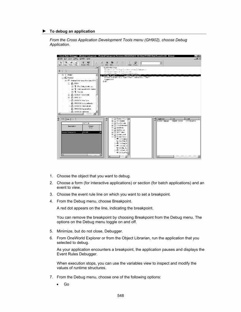
► To debug an application
From the Cross Application Development Tools menu (GH902), choose Debug Application.
1. Choose the object that you want to debug.
2. Choose a form (for interactive applications) or section (for batch applications) and an event to view.
3. Choose the event rule line on which you want to set a breakpoint.
4. From the Debug menu, choose Breakpoint.
A red dot appears on the line, indicating the breakpoint.
You can remove the breakpoint by choosing Breakpoint from the Debug menu. The options on the Debug menu toggle on and off.
5. Minimize, but do not close, Debugger.
6. From OneWorld Explorer or from the Object Librarian, run the application that you selected to debug.
As your application encounters a breakpoint, the application pauses and displays the Event Rules Debugger.
When execution stops, you can use the variables view to inspect and modify the values of runtime structures.
7. From the Debug menu, choose one of the following options:
• Go
548

• Stop
• Step Over
• Step Into
Inspecting or Modifying a Variable
As you debug an application and encounter a point at which the interactive or batch application fails, modify the appropriate variable to correct it. Save your modifications and rerun the application to see if further debugging is required.
► To modify a variable
1. On event Rules Debugger, double-click a variable in the Event Rules Variables window.
2. Revise the information in the following field:
• New Value
Just in Time Debugging
The Event Rules Debugger also uses "Just in Time Debugging." Just in Time Debugging occurs after you build the debug information, run the Event Rules Debugger, and then run the application.
If the runtime engine has a problem resolving an event rule object or calling a business function, a message box appears that allows you to activate the Debugger. If you choose to
549
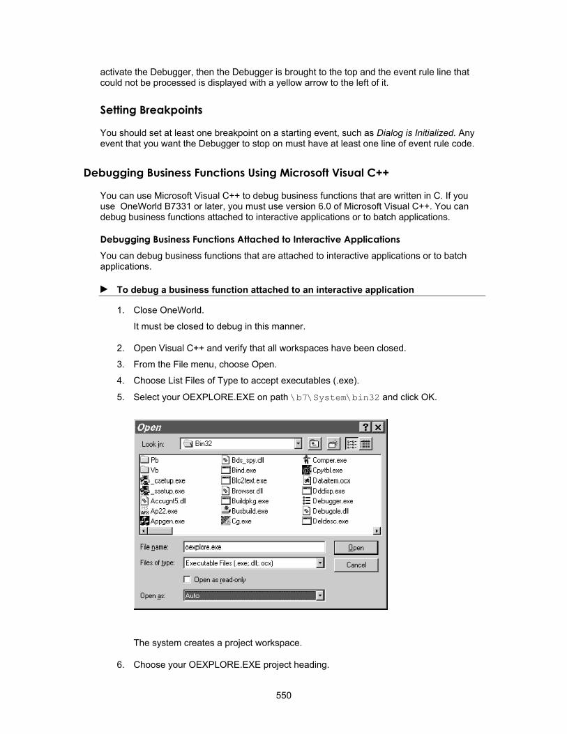
activate the Debugger, then the Debugger is brought to the top and the event rule line that could not be processed is displayed with a yellow arrow to the left of it.
Setting Breakpoints
You should set at least one breakpoint on a starting event, such as Dialog is Initialized. Any event that you want the Debugger to stop on must have at least one line of event rule code.
Debugging Business Functions Using Microsoft Visual C++
You can use Microsoft Visual C++ to debug business functions that are written in C. If you use OneWorld B7331 or later, you must use version 6.0 of Microsoft Visual C++. You can debug business functions attached to interactive applications or to batch applications.
Debugging Business Functions Attached to Interactive Applications You can debug business functions that are attached to interactive applications or to batch applications.
► To debug a business function attached to an interactive application
1. Close OneWorld.
It must be closed to debug in this manner.
2. Open Visual C++ and verify that all workspaces have been closed.
3. From the File menu, choose Open.
4. Choose List Files of Type to accept executables (.exe).
5. Select your OEXPLORE.EXE on path \b7\System\bin32 and click OK.
The system creates a project workspace.
6. Choose your OEXPLORE.EXE project heading.
550

7. From the Project menu, choose Settings.
8. Click the Debug Tab.
9. In the Category list, choose Additional DLLs.
10. Click the Browse button to select the CALLBSFN.dll or other appropriate DLL on path \b7\bin32.
This path might vary depending on your path code.
551

11. Click OK.
12. Choose your .h and .c files for the source you want to debug from file open.
13. From the Edit menu, choose Breakpoints to set breakpoints in your code.
If a cannot open *.pdb message appears, click OK.
If a message appears notifying you that breakpoints have been moved to the next valid lines, a source code and object mismatch might exist, and you might need to rebuild your business function.
14. From the Build menu, choose Start Debug, Go.
The OneWorld signon window appears.
15. Sign on to OneWorld as you normally would.
16. Execute the application.
When it reaches the business function in Debug, it opens or displays the C code in Visual C so that you can step through it.
If you are debugging event rules for business functions and C business functions, you can use the OneWorld debugger and the Visual C++ debugger together. Follow the steps above until you log into OneWorld. At that point, follow the steps for the OneWorld debugger. Program execution stops if C code is accessed. You can then use Visual C++ to continue debugging. This is useful if you are trying to locate a problem and you are not sure whether the problem is in a C business function or in the application that calls the business function.
Debugging Business Functions Attached to Batch Applications You can debug business functions that are attached to interactive applications or to batch applications.
552

► To debug a business function attached to a batch application
1. Close OneWorld.
It must be closed to debug in this manner.
2. Open Visual C++ and verify that all workspaces are closed.
3. From the File menu, choose Open.
4. Choose List Files of Type to accept executables (.exe).
5. Select LaunchUBE.exe
6. On LaunchUBE, browse for the report and version that you want to use.
7. Complete the Server Name field by selecting the location in which the report will run.
553

You can choose Local or specify a server.
8. Set the Debug Level
9. Click one of the following Print Options:
• On Screen
• To Printer
10. Click Submit to submit the report.
Working with the Visual C++ Debugger
You must use the Microsoft Visual C++ Debugger to debug business functions written with the Event Rules scripting language or C code. You can run the entire OneWorld system through the Visual C++ debugger (that is, you can start the oexplore.exe file from within the Visual C++ Debugger). This allows you to "step out" of the CASE tool-generated application code into the business functions that are called in the event rules.
You can use the debugger to debug a C program and interactively stop and start it as needed. During debugging, you can check specific values of variables and parameters to ensure a program is running correctly. You can also step through the code to see what code is actually being executed.
The debug commands are listed in the Debug menu. You can customize the toolbar to contain debug buttons, which you can use instead of the menu.
Useful Features of the Visual C++ Debugger
The Visual C++ has many features in the Debug menu. The Visual C++ debugger helps you efficiently solve real-world problems.
The Go Command
You can run a program using the Go command from the Debug menu. The program will run until completion unless you set up breakpoints.
The Step Command
The Step command is available on the Debug menu and executes the current line of code. When the line of code has been executed, the yellow arrow cursor appears on the next line of code to be executed.
The Step Into Command
You can access the Step Into command from the Debug menu. Use this command when the current line of code contains a function call. The debugger steps into the function so that it can be debugged line by line. When the function is complete, the debugger returns to the next line of code after the function call in the calling routine. If the source code of the function to be stepped into does not exist on the workstation, the debugger skips over the line of code as though the Step command was used.
Stepping into a standard C function takes you into the function, which you may not want to do. If so, use the Step Over command to skip those functions.
554
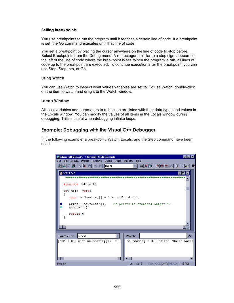
Setting Breakpoints
You use breakpoints to run the program until it reaches a certain line of code. If a breakpoint is set, the Go command executes until that line of code.
You set a breakpoint by placing the cursor anywhere on the line of code to stop before. Select Breakpoints from the Debug menu. A red octagon, similar to a stop sign, appears to the left of the line of code where the breakpoint is set. When the program is run, all lines of code up to the breakpoint are executed. To continue execution after the breakpoint, you can use Step, Step Into, or Go.
Using Watch
You can use Watch to inspect what values variables are set to. To use Watch, double-click on the item to watch and drag it to the Watch window.
Locals Window
All local variables and parameters to a function are listed with their data types and values in the Locals window. You can modify the values of all items in the Locals window during debugging. This is useful when debugging infinite loops.
Example: Debugging with the Visual C++ Debugger
In the following example, a breakpoint, Watch, Locals, and the Step command have been used.
555

• A breakpoint has been set on the line of code with the call to printf. The red "stopsign" is to the left of the code. The call to printf has been executed with the Step command.
• The current line to execute has a yellow arrow to the left of it. It contains a call to the getchar function. That line of code has not yet been executed.
• szGreeting can be seen in the Locals window and in the Watch window. You can scroll these windows horizontally so you can see the entire line. You can see the beginning of the value of szGreeting in the Watch window in the example.
• A plus sign next to a variable in the Locals and Watch windows indicates the data may be expanded. This is useful for inspecting the values of complex data structures.
Customizing the Environment
You can modify the Visual C++ debugging environment. You can customize the editor, colors, fonts, debugger, default directories, workspace, and help.
► To customize the environment
1. From the Tools menu, select Options.
Debugging Strategies
2. On Options, customize your environment as desired.
For more information, refer to the online help for Visual C++.
You can use several strategies to make debugging faster and easier. Begin by observing the nature of the problem.
556

Is the Program Ending Unexpectedly?
The cause of an unhandled exception is a failure to handle memory correctly. It is an easy problem to track down if it is happening in the same place. Simply set breakpoints at strategic points throughout the code and run the program until you find the problem.
If the problem resides in C code, you can find the problem by tracing into the code.
If the problem exists in the OneWorld-generated code, finding the problem may be more difficult. The debugger provides error messages that are helpful. The most common problem has to do with missing objects. If there is a business function that is being called that does not exist, the tool issues an error message that identifies the missing function. For example, "Business function load failed - CALLBSFN.DLL." In this case, you can either rebuild the business function or check it out and build it using BusBuild to correct this error.
Remember that ALL business functions are built into larger DLLs. The most generic of these is CALLBSFN.DLL. Most application specific DLLs are not in CALLBSFN. For example, J.D. Edwards financial business functions use CFIN.DLL.
The object (BSN func) may need to be checked out to the workstation again and built through BusBuild again in CALLBSFN.DLL (or the specific DLL).
If other objects are missing, termination will be more abrupt. Remember to transfer all Media Object (also called Generic Text) objects correctly. If an application has a row exit to an application that does not exist, it immediately causes an unhandled exception in the program.
Termination of the program is more abrupt and less helpful when there are other kinds of objects missing. You must review all of the pieces of your application to make sure that they are all present and correctly built. A common error is to forget about media objects. If you cannot enter your program at all, a missing object is most likely the problem.
Make sure that the program is terminating in the same place. If the program is failing to free memory after its use, the program may eventually have insufficient memory to run. If so, you must reboot the workstation to free memory.
Is the Application Encountering Errors?
When a business function is called from event rules, its processing is unknown to the user. This is both a benefit and a hindrance.
• It is a benefit because it should not be a concern to the user how the function works, only that it does work.
• The disadvantage is that it is not uncommon to call a function with more than 50 parameters, any one of which might cause errors.
There are two solutions to this sort of issue:
• Review the function specifications to make sure that you have hooked it up correctly.
• Step into the code to see what is going wrong.
Is the Output of the Program Incorrect?
If the output of the program is incorrect it means that there is a logic flaw in the code. Trace into the code to find the issue.
557

Where Could the Problem Be Coming From?
• Step through every code path.
Spend some time thinking about where the source of the problem might be.
For example, consider the "Null pointer error." Somewhere in the code memory is a memory leak. To help you determine where the leak is, you can toggle between the grid rows in order to force the execution of the Row is Exited event. If the problem occurs, you have narrowed your search for the leak, because you know that it is in the grid processing.
Is the Function Being Called as Expected?
You can set a breakpoint at the beginning of a called function to ensure that it is being called and that the input is what you expected.
Set the break point at the beginning of the business function or at the beginning of an event like Grid Row is Fetched.
Use the debugger to test the code. Both the J.D. Edwards Debugger and the Microsoft Visual C++ Debugger provide you with the ability to modify values as the code is running. Use this ability to trace through every line of code. This is also a powerful way to test everything that could happen to your code, not just what should happen to it. This form of testing will help demonstrate whether you have handled errors correctly.
For example, step through an If branch and input bad data to see if errors occur as expected.
• Find the cause of the problem, not the symptom.
• Look for problems with object transfer/reinstall.
Debug Logs
There are several sections of the jde.ini file that relate to debugging. The first statement that must be checked is in the [JDE_CG] section. The line Target = Release should be modified to read Target = Debug. An application install of OneWorld will deliver the jde.ini file with Target = Release. To debug business functions, the jde.ini files must be changed to Target = Debug, and the business functions that you wish to debug must be rebuilt.
[JDE_CG]
STDLIBDIR=c:\MSDEV\LIB
TPLNAME=EXEFORM2
ERRNAME=CGERR
TARGET=Debug
INCLUDES=c:\MSDEV\INCLUDE;$(SYSTEM)\INCLUDE;$(SYSTEM)\INCLUDEV; $(SYSTEM)\CG;$(APP)\INCLUDE;
LIBS=c:\MSDEV\LIB;$(SYSTEM)\LIB32;$(SYSTEM)\LIBV32;$(APP)\LIB32;
MAKEDIR=c:\MSDEV\BIN
USER=DEMO
You can output to a file a log of SQL statements and events by changing the line in your jde.ini file under [DEBUG] from Output = NONE to Output = FILE. This is a very useful
558
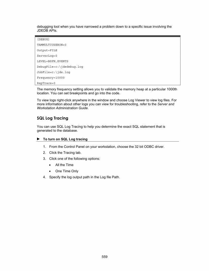
debugging tool when you have narrowed a problem down to a specific issue involving the JDEDB APIs.
[DEBUG]
TAMMULTIUSERON=0
Output=FILE
ServerLog=0
LEVEL=BSFN,EVENTS
DebugFile=c:\jdedebug.log
JobFile=c:\jde.log
Frequency=10000
RepTrace=0
The memory frequency setting allows you to validate the memory heap at a particular 1000th location. You can set breakpoints and go into the code.
To view logs right-click anywhere in the window and choose Log Viewer to view log files. For more information about other logs you can view for troubleshooting, refer to the Server and Workstation Administration Guide.
SQL Log Tracing
You can use SQL Log Tracing to help you determine the exact SQL statement that is generated to the database.
► To turn on SQL Log tracing
1. From the Control Panel on your workstation, choose the 32 bit ODBC driver.
2. Click the Tracing tab.
3. Click one of the following options:
• All the Time
• One Time Only
4. Specify the log output path in the Log file Path.
559

Debug Tracing
Use debug tracing to trace database and runtime events, business functions, and system functions. You can turn on debug tracing and output the results in a log file. This debug log is also useful for checking to see how the tool constructs a SQL statement.
Turning On Debug Tracing
► To turn on debug tracing
1. In the jde.ini file under [DEBUG], change Output=NONE to one of the following values:
Output=FILE This prints both database tracing and runtime tracing.
Output=EXCFILE This prints runtime tracing only.
2. Change Level= to suit your specific debugging needs.
Possible values for Level are contained in the comment line following the Level= line. Any combination is acceptable. Use commas to separate values. The possible values for Level are:
EVENTS This prints when an event starts and when it finishes.
BSFN This prints when business functions are entered and when they return.
560
SF_? This prints when system functions execute. In place of the ?, you can designate a specific type of system function, such as control or messaging.
System Function Tracing
System functions are grouped by category (same categories as design time). Where reasonable, information has been provided about what the system function is acting upon. For example, in many of the grid system functions the row number is printed. For most control system functions the alias of the control and the control ID is printed.
The following example shows the jdedebug.log output running Journal Entry with the following jde.ini options
Output=EXCFILE
Level=EVENTS,BSFN,SF_GRID,SF_CONTROL
561

562
Web Applications
Developing Web Applications
The OneWorld Development Tools make it easy for you to develop and maintain applications for use on both Windows clients and Web clients, even if the clients require slight differences in the design of the forms. You can create Windows, Java, or HTML applications. As you design a form, Form Design Aid allows you to view it in one of three modes. Your design team should decide which modes to use for which client types. For example, you might use Mode 1 for forms to be generated in Windows, Mode 2 for forms you want to generate in Java, and Mode 3 for forms you want to generate in HTML.
Most of the controls you put on a form are appropriate for any of the modes, but you can choose to show or hide (enable/disable) any control on the form for each of these three modes. In this way, you can develop one set of forms from which you generate three versions of the application (one for each mode). If you customize any of the OneWorld Web applications, or if you develop new ones, you must use the Web Generation Facility to generate them into Java or HTML applications. See Working with Controls for more information about using different modes and customizing the controls on forms for different modes.
You typically create an application in Mode 1, the default mode. This application is automatically enabled for Windows. You can then use Mode 2 or Mode 3 to modify your Mode 1 application for Java or HTML.
In the examples below, you can see the kinds of changes you might want to make in a windows application to make it easier for use on the Web. Typically you use fewer fields in a Web application to make it easier for an end user to view and use.
Although you can develop or change Web-based applications (Java or HTML), on your workstation, you need a workstation that is web enabled to test the application. All OneWorld clients are web enabled. The following components are required for your client:
• Internet Explorer 4.01 or above
• OneWorld Web Generation Facility (Installed with OneWorld client)
• Connectivity to a OneWorld Web server
If you customize any of the J.D. Edwards web applications you must regenerate them to create the specified Java or HTML applications. Or, if you create new applications, you must generate those to create Java or HTML applications.
Note Changing the font size in your style sheets can alter the appearance of the form, including displacing controls, and wrapping or hiding control text.
Here is the Windows version (Mode 1) of an application:
563

You can modify your Mode 1 application and use another mode, for example Mode 2, to create an application for Java:
564

You can use another mode, for example Mode 3, to further modify your Mode 1 application for an HTML application:
After you create an application in form design you can use Menu Design to attach the application to a menu and designate which mode the application should run in. You should specify the mode on the menu so that the user can tell which application to use. See Menu Design for more information about designing menus.
To test a Java application you must:
• Save your application in Form Design
• Generate the application to the Web server
• Attach the application to a menu and designate which mode it should run in
• Execute the application
To create web applications, use OneWorld Development Tools in the same manner as you would for standard applications.
If you use OneWorld Development Tools to create your own applications, and these applications are designed for use as web applications, you should consider the following in order to ensure optimal performance:
• Each data and business function request executes on a data or enterprise server, not the web server. As a result, your web client performance is limited by the speed of your network or modem connection as well as network traffic bottlenecks. If possible, you should limit or bundle data and business function requests in a manner most
565

efficient for WAN and Internet connections. If you have several table I/O calls serially linked (for example, each one is dependent on the previous call), consider using named event rules to combine all calls, which are compiled and executed on the enterprise server.
• Whenever possible, design the web-ready application to perform logic using event rules. This provides better performance than if you use C language business functions or event rules business functions (named event rules). Remember, whenever you call a business function the logic is performed on the remote OneWorld enterprise server. However, as mentioned above, if the event rules contain several table I/O or business function calls serially linked, these will perform better as a business function (named event rule) on the enterprise server.
• Design the web-ready application to get data in manageable chunks. If your application performs a business function request before and after each grid line, your performance will suffer. Also, you should try to avoid using business functions as a means to request data; use business views or table I/O instead.
• Educate users in the importance of using search criteria in query by example columns. This is important given the constraints of transferring data at modem speeds across typical Internet connections. For example, users should routinely try to narrow their searches, because data retrievals are configured to only obtain 10 records at a time. If you develop custom applications for web use, consider defining query by example fields as required entries.
Application P98305W is a version list application created specifically for the web client. You can use this application to look up web versions of applications.
See Also Designing Forms Using Multiple Modes
Understanding the HTML Client
The HTML client automatically posts (refreshes) on the following critical events:
• Form startup
• Set focus on grid (only when ER exists)
• Checkbox (only when ER exists)
• Radio button (only when ER exists)
• Bitmap clicked
• URL clicked
• Tab is selected
• Node expanded in tree control
• Drag-and-drop action occurs in tree control
In addition to the critical events listed above, the client also refreshes the page when non-critical events occur that contain hide/show or enable/disable grid functions. The following is a list of these non-critical events:
For Edit controls Control is exited
Control is exited and changed-inline
Control is exited and changed-asynchronous
566
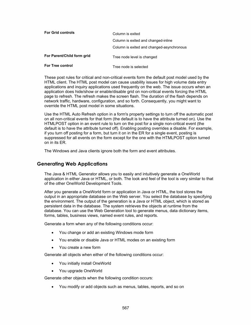
For Grid controls Column is exited
Column is exited and changed-inline
Column is exited and changed-asynchronous
For Parent/Child form grid Tree node level is changed
For Tree control Tree node is selected
These post rules for critical and non-critical events form the default post model used by the HTML client. The HTML post model can cause usability issues for high volume data entry applications and inquiry applications used frequently on the web. The issue occurs when an application does hide/show or enable/disable grid on non-critical events forcing the HTML page to refresh. The refresh makes the screen flash. The duration of the flash depends on network traffic, hardware, configuration, and so forth. Consequently, you might want to override the HTML post model in some situations.
Use the HTML Auto Refresh option in a form's property settings to turn off the automatic post on all non-critical events for that form (the default is to have the attribute turned on). Use the HTMLPOST option in an event rule to turn on the post for a single non-critical event (the default is to have the attribute turned off). Enabling posting overrides a disable. For example, if you turn off posting for a form, but turn it on in the ER for a single event, posting is suppressed for all events on the form except for the one with the HTMLPOST option turned on in its ER.
The Windows and Java clients ignore both the form and event attributes.
Generating Web Applications
The Java & HTML Generator allows you to easily and intuitively generate a OneWorld application in either Java or HTML, or both. The look and feel of the tool is very similar to that of the other OneWorld Development Tools.
After you generate a OneWorld form or application in Java or HTML, the tool stores the output in an appropriate database on the Web server. You select the database by specifying the environment. The output of the generation is a Java or HTML object, which is stored as persistent data in the database. The system retrieves the objects at runtime from the database. You can use the Web Generation tool to generate menus, data dictionary items, forms, tables, business views, named event rules, and reports.
Generate a form when any of the following conditions occur:
• You change or add an existing Windows mode form
• You enable or disable Java or HTML modes on an existing form
• You create a new form
Generate all objects when either of the following conditions occur:
• You initially install OneWorld
• You upgrade OneWorld
Generate other objects when the following condition occurs:
• You modify or add objects such as menus, tables, reports, and so on
567

Note Users without administrative rights are restricted to generating forms and reports privately. Administrators can generate all objects publicly.
See Also Understanding Workstation jde.ini Settings in the OneWorld System Administration
documentation guide for information on gaining administrative rights to the Java & HTML Generator
Logging in
Before you can use the generation tool, you must log in to the web server to which you want to generate objects.
► To log in
1. Launch the Java & HTML Generator application.
The method you use to launch the Java & HTML Generator varies based on your environment and set up. See the J.D. Edwards Knowledge Garden for the most recent set up information.
2. On Java & HTML Generator, click the Admin tab, and then enter the web server you want to use in the Server Name field.
3. Click OK.
Setting Generator Options
Before generating objects, you can define a variety of parameters that will affect how the Java & HTML Generator functions, including defining the TAM path, error and ER log locations, protocol, and language.
Note Some options are available only to users with administrative privileges.
The following table describes the parameters you can configure for the Java & HTML Generator.
Function Description
Define remote TAM path
Enter a TAM path in the Remote TAM Path field on the Admin tab to use a remote TAM for generation.
Define protocol Click the HTTP or the HTTPS option on the Admin tab to generate web applications with one protocol or the other.
Generate error log To generate an error log when the Java & HTML Generator runs, click Error Log on the Admin tab, and then indicate where you want the file to be output.
568
Generate ER log To generate an ER log when the Java & HTML Generator runs, click ER Log on the Admin tab, and then indicate where you want the file to be output.
Generate objects publicly or privately
A user with administrative rights may choose to generate objects privately or publicly. Click the Personal or Private option on the Admin tab to generate web applications one way or the other.
Choose output language
To generate objects in multiple languages, click the languages you want on the Language tab. For each non-default language you choose, you must indicate a TAM path.
See Also Understanding Workstation jde.ini Settings in the OneWorld System Administration
guide for information on gaining administrative rights to the Java & HTML Generator
Generating Forms
If you changed or added an existing Windows mode application, if you added a new form, or if you enabled or disabled modes, you must generate the form before you can use the web version of the form. You can generate all the forms at once, or you can generate the forms for an application or system code. The Java & HTML Generator always generates Java for the modes you select. Additionally, you can choose to generate HTML for the selected modes as well.
► To generate selected forms
1. On Java & HTML Generator, click the Form tab.
2. To generate the forms in an application, click Application, and then complete the following fields:
• Object Name
Enter the system name of the application.
• Form
To generate a specific form only, enter the system name of the form. If you leave this field blank, the system generates all the forms in the application.
• Version
To generate a specific version of a form, enter the system name of the version. If you leave this field blank, the system generates all versions of the form or forms.
Go to step 4.
3. To generate the forms in a system code, click System Code, and then complete the following field:
• Object Name
Enter the system code.
Go to step 4.
4. Click Generate Business Views to generate the business views associated with the object you specified in step 2 or 3.
569

5. Click the modes (1, 2, or 3) for which you want to generate forms.
You can generate forms in one or more modes.
6. To generate forms in HTML, click Generate HTML version.
When you select this option, the system generates HTML versions of the forms for each selected mode.
7. If you are generating HTML versions of the forms, you can put a footer on the forms by entering a task ID in the Footer Menu field.
If you enter a task ID, the ID will be generated as a hyperlink, allowing a user to launch a OneWorld task. For example, if you entered the task ID for the Journal Entry application (2/G0911), a user could launch Journal Entry by clicking on the form's footer.
Leave this field blank if you do not want footers to appear on the forms.
8. Click OK.
► To generate all forms
1. On Java & HTML Generator, click the Form tab.
2. Click Generate Business Views to generate the business views associated with the forms.
3. Click the modes (1, 2, or 3) for which you want to generate forms.
You can generate forms in one or more modes.
4. To generate forms in HTML, click Generate HTML version.
When you select this option, the system generates HTML versions of the forms for each selected mode.
5. If you are generating HTML versions of the forms, you can put a footer on the forms by entering text in the Footer Menu field.
If you enter a task ID, the ID will be generated as a hyperlink, allowing a user to launch a OneWorld task. For example, if you entered the task ID for the Journal Entry application (2/G0911), a user could launch Journal Entry by clicking on the form's footer.
6. Click Generate All.
Generating Reports
If you added or changed reports (batch applications or batch versions), you must generate the report to make the report available on the web. Batch applications are available in Java format only.
You can generate all of the reports and their versions in the system, or you can generate selected reports based on report name or system code.
570

► To generate selected reports
1. On Java & HTML Generator, click the Reports tab.
2. To generate a specific report or batch version, click Report, complete the following fields, and then click OK:
• Object Name
Enter the system name of the report.
• Version
To generate a specific version of a report, enter the system name of the version. If you leave this field blank, the system generates all versions of the report.
3. To generate the reports and their versions in a system code, click System Code, complete the following field, and then click OK:
• Object Name
Enter the system code.
► To generate all reports
1. On Java & HTML Generator, click the Reports tab.
Ensure all the fields on the Reports tab are blank.
2. Click Generate All.
Generating All Objects
Generate all objects only at initial OneWorld installation, when you have extensive changes or additions to all applications, or if you are installing an upgrade. This process takes several hours.
► To generate all objects
1. On Java & HTML Generator, click the Admin tab.
2. Click Generate All.
Generating Other Objects
If you have administrative rights to the Java & HTML Generator, you can generate other objects in addition to forms and reports such as menus, data dictionary items, and tables. Occasional changes to such objects in OneWorld might impact how OneWorld applications function without affecting their appearance. In such cases, you can save time by generating only those objects that have changed without having to generate an application and all of its supporting objects.
See Also Understanding Workstation jde.ini Settings in the OneWorld System Administration
documentation for information on gaining administrative rights to the Java & HTML Generator
571

► To generate menus
1. On Java & HTML Generator, click the Menu tab.
2. Click Generate All.
► To generate data dictionary information
1. On Java & HTML Generator, click the DD Info tab.
2. Click one of the following options, depending on the type of object you want to generate:
• Data Dictionary
• Table ID
• Business View
Skip this step if you want to generate all data dictionary items.
3. Enter the name of the object you want to generate in Object Name.
Leave this field blank if you want to generate all data dictionary items.
4. Click OK to generate a single object. Click Generate All to generate all data dictionary items and their related table ID and business view references.
► To generate business views and tables
1. On Java & HTML Generator, click the BSVW & Table tab.
2. Click one of the following options, depending on the type of object you want to generate:
• Business View
• Table
Skip this step if you want to generate all business views and tables.
3. Enter the name of the object you want to generate in Object Name.
Leave this field blank if you want to generate all business views and tables.
4. Click Generate Data Dictionary to generate the data dictionary items associated with the object or objects to be generated.
5. Click OK to generate a single object. Click Generate All to generate all business views and tables.
► To generate data structures
1. On Java & HTML Generator, click the BSFN & Data Structure tab.
2. Click one of the following options, depending on the type of object you want to generate:
• BSFN's data structure
• UBE's data structure
• BSFN view for storefront
3. Enter the name of the object you want to generate in Object Name.
572

4. Click OK.
► To generate named event rules (NERs)
1. On Java & HTML Generator, click the NER tab.
2. Enter the name of the object you want to generate in Object Name.
Leave this field blank if you want to generate all NERs.
3. Click Dependencies to generate the dependencies associated with the object or objects to be generated.
4. Click OK to generate a single object. Click Generate All to generate all NERs.
573
Performance
This section includes tips and tools to help you enhance the performance of your applications.
Performance Tips
This section describes some things you can look for to improve performance. In particular it provides information about analyzing and improving the performance of:
• Data Dictionary
• Table Design
• Business Views
• Data Structures
• Data Selection and Sequencing
• Form Design
• Batch Applications
• Event Rules
• Business Functions
• Error Messaging
• Transaction Processing
Things to Look For
Does the application seem slow on all platforms? If yes, then further analyze the application.
Does the application seem slow on a specific platform, but not all platforms? If yes, then there may be a logical issue or index issue for the given platform.
There are several tools to perform this analysis. Use jdedebug.log first to determine at what event the application seems slow and what is happening on that event.
Analyze database and business function use. In analyzing the tables, consider the following:
• Records should be read in only once unless all secondary fetches for a given record were cached.
• The total of all JDB_OpenTable and JDB_OpenTableFromCache should match the total number of JDB_CloseTable calls for each table.
• The total number of actual JDB_OpenTable calls (the amount of opens that are not cached) should be as close to one as possible. Values larger than one indicate that multiple database cursors are being retained for the table.
Next turn on table logging for the jdedebug.log. Review the database I/O. If the table I/O is still a concern, start the SQL log and analyze the information in the log.
If you have justified all table I/O, and the application is still slow on certain events, then review the business functions running on those events. Make sure the business functions are running efficiently.
574
Look for business functions accessing a table a large number of times for the number of records being processed. Can caching be used?
Look for values that can be saved in global event rule variables instead of performing redundant I/O calls.
Look for multiple calls to multiple business functions running over the same table that can be consolidated into one table I/O call.
Look for business function or table I/O calls that can be moved to different events in order to reduce the number of times that they are called.
Look for business functions calling other business functions unnecessarily.
Data Dictionary Performance
Triggers
Data dictionary triggers can be used for both formatting and validation. Triggers are the most costly way to format or edit data values. Most of the formatting that occurs in OneWorld involves date and math fields. These fields require the most overhead for editing and formatting. Make sure that all triggers are coded as efficiently as possible.
Overrides
You can use data dictionary overrides to override the data dictionary characteristics of a form control, grid column, or report field at design time. This causes additional overhead at application startup because of the extra processing required to evaluate and apply the overrides. The overrides that are applied can have either a positive or negative affect on performance during runtime processing. For example if you use the override feature to disable some of the validation functionality, then performance will be increased, because disabling features causes some runtime overhead to be removed. Adding overrides such as edit/format triggers or next numbering will increase runtime overhead.
Validation
Validation is based on the data dictionary item that is attached to a control, column, or field. The overrides can also play a part in validation. Validation is the most costly for data items that have triggers. Validation of user defined codes also requires I/O to validate data values. General validation can be more costly for certain data types such as Math and Date. These data types require special logic to manipulate the OneWorld-specific data types.
Table Design Performance
Be careful using SELECT statements. Try to use existing indices for a table. It is better to use additional keys than to create a new index. Additional indices create overhead.
Use a partial key only for sequential and fetch next or just to look at a few more records.
If you open a table and then a fetch key, it destroys the pointer so do a fetch single instead. Almost any other database API will destroy the pointer also.
Opening a table the first time is a big performance hit.
575

The fetch matching key uses a greater than or equal key so it selects more than you may need. Use the correct JDB API for what you need.
Index Considerations Adding a suitable index will almost always improve performance when selecting and fetching data from the database. However, each additional index adds maintenance overhead when records are added, updated or deleted in the database. The decision about adding a new database index over a table should balance these two factors.
OneWorld accesses databases efficiently. Use ordinary database design considerations, including normalization considerations, when determining the optimal design of database tables and indices.
Join fields should be the keys in two tables.
Limits on Row Set Size The lowest common denominator for row size is the specification given in the SQLSERVER database.
SQL Server 6.5 can have as many as 2 billion tables per database and 250 columns per table. The maximum number of bytes per row is 1962. If you create tables with varchar or varbinary columns whose total defined width exceeds 1962 bytes, the table is created but a warning message appears.
Inserting more than 1962 bytes into such a row or updating a row so that its total row size exceeds 1962 produces an error message and the statement fails.
Considerations for Coexisting with WorldSoftware Make sure tables in OneWorld match AS/400 tables. If the data is not structured the same it causes problems.
If you plan custom modifications in a coexistence environment, the World RPG programs must be able to read the structure of any tables to be read by WorldSoftware. This means that the tables WorldSoftware must access should be initially created in World database structure, not from OneWorld using AS/400 foreign databases (Access, Oracle, SQL Server). The World environment must be set up first before OneWorld is set up on top of it.
Make date and time conversions on AS400 and OneWorld the same.
Refer to the Coexistence Guide for more information about coexistence.
Index Limitations for Various Databases
Access32
The following index limitations apply to Access 32:
• The maximum number of indices per table is 32.
• The maximum number of fields in an index is 10.
• The maximum number of fields in a records is 255.
576

SQLSERVER
The following index limitations apply to SQLSERVER:
• The maximum number of clustered indices per table is one.
• The maximum number of nonclustered indices per table is 249.
• The maximum number of columns in a composite index is 16.
DB2 for OS/400
The following index limitations apply to DB2 for OS/400:
• The maximum number of identifiers for an index name is 10.
• The maximum size of an index is 1 terabyte.
• The maximum length of an index key is 2,000.
• The maximum number of columns per index key is 120.
• The maximum number of indexes per table is approximately 4,000.
This is not permitted, because the key length in this case is 1101 (>900).
Oracle
The following index limitations apply to Oracle:
• The maximum length for an index is 254 bytes, less the number of keys that allow NULL values.
• The maximum number of columns per index is 16 or a maximum key length of 900.
Example: Table Index In the F32944 table, the index is defined as follows:
{
MATH_NUMERIC ktkit; /* 0 to 48 */
char ktmc01[251]; /* 49 to 299 */
char ktmc02[[252]; /* 300 to 550 */
char ktmc03[251]; /* 551 to 801 */
char ktmc04[251]; /* 802 to 1052 */
MATH_NUMERIC ktseqn; /* 1053 TO 1101 */
} KEY1_F32944, FAR *LPKEY1_F32944;
#define ID_F32944_KIT_CONFIGURED_STRING_ID_B 2L
Key Column Violation
When you define indexes on various columns, ensure that no two indices, one of which may be a primary unique index, are defined on the same column.
Example: Key Column Violation In the F03B08 table, the indexes were defined as:
577

This is not permitted, because two indexes are defined on the same columns.
Specification File Corruption
If you encounter specification file corruption, recreate the tables in the source database.
Table I/O Objects
Table I/O header size is 206 bytes.
Table I/O mapped item size is 181 bytes.
Maximum number of table I/O mapped items size to fit in 32K is (32768-206)/181 for about 180 items.
In order to leave space for literal values, use a mapping size not greater than 130 elements. The 130 elements relate to the number of mappings on any table I/O statement. A table may have more than 180 columns, but you can still map fewer than 180 of them without problems. If you need to use table I/O with more than 180 mappings, you should probably create several table I/O statements for specific requirements.
Business View Performance
Should I use a single-table or multiple-table business view? In many instances, the application needs to access data from multiple database tables to perform a business operation. You can accomplish this in two ways:
• Use a multiple-table business view to access all the related data fields
• Use a single-table business view to access the data fields from the primary table, and use a business function or table I/O to access the data fields from secondary tables
578

The best choice is not always obvious, but you can usually decide by looking at the resulting number of database I/O operations that will be performed. A joined business view that uses cross data source joins causes slower performance.
If the secondary tables are "master" files, the second option is usually preferable because it makes best use of database caching. For example, suppose the primary table contains a company number and the related company name is stored in a secondary Company Master file. If, in practice, it is likely that the same Company Master record will be retrieved for several records in the primary table, then it is usually preferable to fetch the company name explicitly using a business function or table I/O.
OneWorld is particularly optimized to fetch user defined codes. User defined code tables should never be included in a multiple-table business view.
Should I restrict the number of fields in a business view? You may need to choose between using an existing business view that may contain fields that are not needed or creating a new business view with only the desired fields. While any extraneous fields cause additional work on both the server and the workstation, this is usually not a significant performance concern. In cases involving tables that will be updated, OneWorld can automatically process all fields in a table, even if they are not included in the business view.
Minimizing the number of fields in a data structure is far more productive in improving runtime performance than minimizing the number of fields in a business view. You can create new business views that meet your specific needs that do not affect performance.
Unions Unions are the most expensive database operation out of all the SQL SELECT statement types. In general you should avoid using them. An example of when you might want to use unions is if you are using the same part of tables at different times. For example, an application uses the same part of 10 different tables, and you only need that part one part at a time. Post Processes is an example of this.
Joined Business View Versus Table I/O Use a joined business view if you are reading and updating two or more major tables. Use table I/O if the table being read or updated is just a side affect of another action.
Consider writing applications with the minimum number of grid columns required for the application's basic functionality. You can add columns to the associated business view to supplement the basic application with minimal effort. Therefore, it is better to add columns to a business view than to add columns to a grid.
Data Structure Performance
Should I restrict the number of fields in a data structure? Performance measurements indicate that you should attempt to minimize the number of fields in a data structure, particularly when Configurable Network Computing (CNC) capabilities require that the data structure be passed between workstation and server.
Data Structure Objects Data structure header size is 237 bytes.
Data structure item size is 72 bytes.
579

Maximum number of data structure items to fit in 32K is (32768-237)/72 for 450 elements.
In order to leave space for literal values you should limit your structure size to 350 elements or less. Any data structure approaching a size of 100 elements or more should be considered carefully.
Data Selection and Sequencing
Use the following two system functions in the Initialize Section event to conditionally change the data selection for that section:
• Set User Selection
• Set Selection Append Flag
The Initialize Section event is normally used in the first level-one section of a report to conditionally select data based on values passed through the report data structure.
For example, Bill of Material Inquiry calls the Bill of Material report passing the Parent Item, Parent Branch, Type of Bill, and Batch Quantity. In the Initialize Section Event of the first level-one section of the Bill of Material report, the report data structure values are checked. If they are not equal to blank, the Set User Selection system function is used to add these selections.
Form Design
This list contains standards for increased performance across all form types.
• Limit the number of columns in the grid to the minimum required by the application.
• Keep the number of columns in the business view to the minimum required by the application.
• Limit the number of form controls, whether hidden or visible, to the minimum required by the application.
• Event rule variables should be used as work fields in place of hidden form controls.
• Disable data dictionary functions on form and grid controls that are not required, such as edits and default values, whether hidden or visible.
• Keep the amount of input and output performed for each grid row to the minimum required for the application. For example, avoid associated descriptions wherever possible.
• Use the Stop Processing system function whenever feasible to skip the processing of unnecessary event rules.
• Consider the design for the most efficient method of temporary data storage available at the time, such as cache versus linked list versus work files.
Find/Browse
This list contains standards for increased performance on Find/Browse forms.
• QBE assignments are not used (they negatively impact performance).
• The sort order on the grid should match both an index defined in OneWorld and a logical defined on the AS/400, either partially or completely. The logical file and index must contain at least all fields that are in the grid sort, and the fields selected for the grid sort must be in the same sequence as the logical/index fields. There may be
580
additional fields in the index or logical that are not included in the grid sort. For example, in a partial match, the grid sort can be KIT, MMCU and the logical and index can include KIT, MMCU, TBM, BQTY.
Header Detail and Headerless Detail
This list contains standards for increased performance on Header Detail and Headerless Detail forms.
• For maximum performance, the grid sort should match an index of the table in the business view. The index should exist on the AS/400 and OneWorld tables.
• The sort order on the grid should match both an index defined in OneWorld and a logical file defined on the AS/400, either partially or completely. The logical and index must contain at least all fields that are in the grid sort, and the fields selected for the grid sort must be in the same sequence as the logical/index fields. There may be additional fields in the index or logical that are not included in the grid sort. For example, in a partial match, the grid sort can be KIT, MMCU7 and the logical and index can include KIT, MMCU, TBM, BQTY.
Batch Application Performance
Setting Up Level Breaks If the sort definition for the section is MMCU, KIT, BQTY, TBM and you want to have a level break on TBM, the level-break indicator must be set for all four fields. A level-break header or footer can then be attached or triggered off a change in TBM.
Slow Performance If the server side performance for your batch process is extremely and you cannot determine the cause, you may want to check with your system administrator to ensure that the RequestedService setting in the JDE.INI file has the appropriate settings.
Event Rules Performance
When you are creating logic, if a row did not change then skip it. Do not check every row for changes.
Put master business function end docs on the Post Button Clicked event.
On asynchronous processing, put the Post Button Clicked event only on OK and Cancel. This ensures that your form does not terminate while the business function is still running. If the form terminates while the business function is still running, the business function cannot return values or handle errors.
Use system functions for repeated processes.
You can also use system functions to get to information that you cannot access, for example to write grid lines.
FetchKeyed is made up of Clear Selection, Select Keyed, and Fetch. Avoid using FetchKeyed unless the keys are changing.
If keys are not changing use Select, and then in a loop use Fetch Next for better performance, only if you do need to read records sequentially.
581

You should hide and show fields on the Dialog is Initialized event. You should put logic on the Post Dialog is Initialized event.
Always code If statements for the usual.
Use explicit comparisons instead of implied. It takes more code, but it runs faster.
You should make sure that the lines in a loop really need to be in there. If something does not really need to be done each time, then do not put it in a loop.
Reduce the number of returns inside code so you have only one exit point.
Use named variables to store temporary values. Do not use hidden controls or grid columns to store temporary values.
Use jdeCache instead of work tables In early versions of OneWorld, developers used temporary local tables to contain working arrays. This technique is now obsolete. The jdeCache routines provide the similar capabilities but with improved performance.
When multiple business functions access the same cache, locate the related functions in the same source member.
For example, an EditGridLine function adds records to a cache and a corresponding EndDocument function retrieves the cached records and inserts them to the database. If the business functions are placed in different source members, a change in the CNC configuration may cause the application to fail.
Should I use JDB API calls in a business function or table I/O commands in event rule code to manage the database? From a performance standpoint, there is little difference between the two methods. Make the choice based on the context. For example, if event rule code needs to access the database, use event rule table I/O instead of writing and calling a business function.
When possible, use JDBFetchNext instead of multiple JDBFetch statements When multiple related database records must be read from the database, it is generally preferable from a performance standpoint to select the records at once and use JDBFetchNext to loop through the qualifying records. The alternative of making multiple calls to JDBFetch is usually considerably slower.
Business Function Performance
You can have data dictionary edits in business functions.
If you have validation in your code and this validation is also part of a master business function, the tool will know that you have already validated and will return and say it is already done, instead of performing the validation twice.
If you go into a grid and do a custom select it is a big performance hit. You might want to restrict people from resequencing the grid. If there is a business need to resequence a grid, make sure there is an index over that table that matches the sort sequence.
Use business function caching to retain pieces in memory.
Do not use linked lists; use caching instead.
Create a structure and pass a pointer instead of adding items.
582

Make sure variables are used only if needed.
Do not use static variables. You should probably use a single record cache instead. An instance where you might want a static variable would be if you were getting parts of something repeatedly and totalling them.
Because jdeAlloc actually allocates space, you should not generally use it. You can, however, use jdeAlloc if you want to keep a storage area for multiple calls.
For example, suppose you have a function that is split into server and workstation components and you have parent/child information. The client makes a request for what the parent/child looks like. The server needs to know where to go back to. You can use jdeAlloc to keep the information in sequence.
jdeCallObject - When functions are built there is one .c in source. If you have more functions in here, then all functions run on the server if the main one does. You may, however, want some functions to run on the workstation and some on the server. Make sure that if you use more than one function that they are all completely dependent and you want them to run on the same place. jdeCallObject goes across DLLs and platforms.
Memory Allocation A memory leak is when allocated memory is not freed when it is no longer needed. This can cause the performance of an application to degrade continuously as it runs. You should be aware that jdeCache allocates memory. A cache that is created in a BeginDoc master business function must be destroyed in the corresponding EndDoc function.
One frequent source of unexpected memory leaks comes from failing to free allocated memory when processing errors or other conditions which may traverse an alternate execution path in a business function.
Look at JDEDEBUG.LOG to identify possible memory leaks in business functions. You can also use a third-party tool for detecting memory leaks.
Balance Table Opens and Closes Be sure to match each jdbOpen with a corresponding jdbClose within the same business function for all possible execution paths. Serious performance problems can arise from unbalanced table opens and closes.
Error Messaging Performance
You can classify error messages in the data dictionary as errors or warnings. An error shows as a red stop sign and a warning is a yellow yield sign. Validation is automatically performed using the data dictionary. Other errors must be checked manually using event rules. Specify the field and error message number the error is from.
You must code an If statement in event rules so that if an error is already shown you do not show it again. If the error is only in the data dictionary, the error will show every time.
Transaction Processing Performance
When you design applications that use transaction processing, you should maintain as narrow a scope as possible and you should start your transaction at a point that allows for the shortest possible time between the start of the transaction and the commitment or rollback. When you update a record that is part of a transaction, it is locked until the transaction is committed. If any part of a transaction fails, the whole transaction rolls back.
583

584

Additional Information for OneWorld Development Tools
OneWorld Modification Rules
Because the OneWorld Tools are comprehensive and flexible, you can customize certain aspects of business solutions and applications without making custom modifications. J.D. Edwards refers to this concept as "modless mods," which are modifications that you can perform easily without the help of a developer. You can perform modless mods on the following:
• User overrides
• User defined codes
• Menu revisions
• All text
• Processing options values
• Data dictionary attributes
• Workflow processes
This kind of flexibility improves efficiency and provides distinct advantages, such as the ability to do the following:
• Export grid records to other applications, such as a Microsoft Excel spreadsheet
• Resequence a grid on a different column
• Change grid fonts and colors
• Control major functionality using processing options
However, even with the full commitment of J.D. Edwards to making the tools as flexible and robust as possible, if the need does arise to modify OneWorld, there are certain rules and standards to ensure that software modifications perform like modless mods for a seamless and predictable upgrade to the next release level.
You should prepare for the upgrade before making any custom modifications to ensure a smooth upgrade. If you plan modifications properly, you will have minimal work to do following an upgrade. This should result in the least amount of disruption to your business and a reduction in the overhead cost involved during an upgrade because the upgrade time is reduced.
OneWorld keeps track of all custom modifications as you check them into the server. Using this feature, you can run the Object Librarian Modifications (R9840D) report prior to a merge to see a list of the changed objects.
OneWorld consists of control tables (such as menus, user defined codes, versions, and the data dictionary) and transaction tables (such as Address Book and the Sales Order File). J.D. Edwards ships the control tables with data that you can modify, while transaction files contain your business data.
Both of these kinds of tables go through an automatic merge process during an upgrade where control tables are merged with new J.D. Edwards data, while transaction files are converted to the new specifications, keeping your existing data. For the object specification merges (such as business view, tables, data structures, processing options, event rules, and
585

applications), there are processes in place that merge the specifications or overlay them depending upon the rules defined under What an Upgrade Preserves and Replaces.
What an Upgrade Preserves and Replaces
If your business needs require custom modifications, observe the following general rules for OneWorld modifications to help ensure a smooth and predictable upgrade. These rules describe which of your modifications the upgrade process preserves and which modifications it replaces.
• "Preserve" means that during an upgrade, OneWorld automatically merges your modifications with the new J.D. Edwards applications shipped with the upgrade, and you do not lose your modifications. If there is a direct conflict between your specifications and J.D. Edwards specifications, the upgrade process uses yours. When there is no direct conflict between the two, then the upgrade process merges the two specifications.
• "Replace" means the upgrade does not merge those types of modifications and, therefore, J.D. Edwards replaces your modifications. You will need to do them again after the upgrade completes.
J.D. Edwards provides you with the Object Librarian Modifications (R9840D) report, which you can run before the upgrade process to identify objects that you modified.
General Rules for Modification
The following general modification rules apply to all OneWorld objects:
• When adding new objects, use system codes 55-59. OneWorld uses reserved system codes that enable it to categorize different applications and vertical groups. By using system codes 55-59 for your custom usage, OneWorld does not overlay your modifications with J.D. Edwards applications.
• Do not create custom or new version names that begin with ZJDE or XJDE. These are reserved prefixes for standard version templates that J.D. Edwards sends out for you to copy, to create new templates or versions. Using these prefixes does not preserve your custom versions in case of a naming conflict.
• For upgrades, you should build a package from the last modified central objects set and perform backups of your development server, central objects, and Object Librarian data sources so you can access those specifications for comparison or for troubleshooting purposes. See the OneWorld Upgrade Guide for information.
Interactive Applications
Do not delete controls, grid columns, or hyperitems on existing OneWorld applications. Instead, hide or disable them. OneWorld might use these items for calculations or as variables, and deleting them might disable major functionality.
What an Upgrade Replaces The following interactive application elements are replaced during an upgrade.
• Custom forms on existing OneWorld applications
Instead of putting custom forms on existing OneWorld applications, it is preferable to create a custom application using system codes 55 - 59, and then place the custom form on that custom application. You can then add to existing applications form exits
586
and row exits that call your custom forms within your custom applications. From a performance standpoint there is no difference if an external application is called from a row exit or a form within the application.
Object Preserved Replaced Comments
New applications
X There are two ways to create an application: create it from scratch, or copy an existing application using the Application Design Aid's "Copy" feature. This allows you to copy all of the application specifications, including event rules.
If you use the Copy feature to copy an existing application for some modifications, during an upgrade your new application does not receive any changes J.D. Edwards might have made to the original application you copied.
New hyperitems added to existing forms
X
New controls added to existing forms
X
New grid columns added to existing forms
X
Style changes X Style changes include fonts and colors. New J.D. Edwards controls have the standard base definitions, so if you adjust the style you need to do the same for any new controls added to an application.
Code-generator overrides
X
Data dictionary overrides
X
Location & size changes
X If J.D. Edwards decides to place a new control in the new release of the software in the same place you have placed a custom control, the controls display on top of each other. This does not affect the event rules or the functionality of the application. After the upgrade, you can rearrange those controls using Application Design Aid.
Sequence changes for tabs or columns
X The upgrade process adds new J.D. Edwards controls to the end of your custom tab sequence. You can review the tab sequence after an upgrade.
Custom forms on existing OneWorld applications
X Instead of putting custom forms on existing OneWorld applications, it is preferable to create a custom application using system codes 55 - 59, and then place the custom form on that custom application. You can then add to existing applications form exits and row exits that call your custom forms within your custom applications. From a performance standpoint there is no difference if an external application is called from a row exit or a form within the application.
587
What an Upgrade Preserves The following interactive application elements are preserved during an upgrade.
• New applications
There are two ways to create an application: create it from scratch, or copy an existing application using the Application Design Aid's "Copy" feature. This allows you to copy all of the application specifications, including event rules.
If you use the Copy feature to copy an existing application for some modifications, during an upgrade your new application does not receive any changes J.D. Edwards might have made to the original application you copied.
• New controls added to existing forms
• New hyperitems added to existing forms
• New grid columns added to existing forms
• Style changes
Style changes include fonts and colors. New J.D. Edwards controls have the standard base definitions, so if you adjust the style you need to do the same for any new controls added to an application.
• Code-generator overrides
• Data dictionary overrides
• Location & size changes
If J.D. Edwards decides to place a new control in the new release of the software in the same place you have placed a custom control, the controls display on top of each other. This does not affect the event rules or the functionality of the application. After the upgrade, you can rearrange those controls using Application Design Aid.
• Sequence changes for tabs or columns
The upgrade process adds new J.D. Edwards controls to the end of your custom tab sequence. You can review the tab sequence after an upgrade.
Reports
The following rule applies to Report Design Aid specifications:
Do not delete objects on existing OneWorld reports. Instead, hide them. OneWorld might use these for calculations or as variables, and deleting them might disable major functionality.
What an Upgrade Preserves The following report elements are preserved during an upgrade.
• New reports
There are two ways to create a report: create it from scratch, or copy an existing report using Report Design Aid's "Copy" feature. This feature enables you to copy all the report specifications, including event rules.
588

If you use it to copy an existing report for some modifications, during an upgrade your new report does not receive any J.D. Edwards' updates made to the original report you copied.
• New reports
• New constants added to existing reports
• New alpha variables added to existing reports
• New numeric variables added to existing reports
• New data variables added to existing reports
• New runtime variables added to existing reports
• New database variables added to existing reports
• New data dictionary variables added to existing reports
• Style changes
Style changes include fonts and colors. New J.D. Edwards controls have the standard base definitions, so if you have adjusted the style, you need to do the same for any new controls added to a report.
• Location and size changes for objects
If J.D. Edwards decides to place a new object, such as a control, in the new release of the software in the same place you have placed a custom object, the objects display right next to each other. This does not affect the event rules or the functionality of the report in any way. After the upgrade, you can rearrange objects using Report Design Aid.
• Data dictionary overrides
Object Preserved Replaced Comments
There are two ways to create a report: create it from scratch, or copy an existing report using Report Design Aid's "Copy" feature. This feature enables you to copy all the report specifications, including event rules.
If you use it to copy an existing report for some modifications, during an upgrade your new report does not receive any J.D. Edwards' updates made to the original report you copied.
New reports X
New constants added to existing reports
X
New alpha variables added to existing reports
X
New numeric variables added to existing reports
X
New reports X
589

New data variables added to existing reports
X
New runtime variables added to existing reports
X
New database variables added to existing reports
X
New data dictionary variables added to existing reports
X
Style changes X Style changes include fonts and colors. New J.D. Edwards controls have the standard base definitions, so if you have adjusted the style, you need to do the same for any new controls added to a report.
Location and size changes for objects
X If J.D. Edwards decides to place a new object, such as a control, in the new release of the software in the same place you have placed a custom object, the objects display right next to each other. This does not affect the event rules or the functionality of the report in any way. After the upgrade, you can rearrange objects using Report Design Aid.
Data dictionary overrides
X
X Instead of adding custom sections to existing reports, use Report Interconnect and connect to a new custom report that uses system codes 55 - 59. There is no difference in the performance of a report being called through report interconnections.
Custom sections on existing OneWorld reports
What an Upgrade Replaces The following report elements are replaced during an upgrade.
• Custom sections on existing OneWorld reports
Instead of adding custom sections to existing reports, use Report Interconnect and connect to a new custom report that uses system codes 55 - 59. There is no difference in the performance of a report being called through report interconnections.
Application Text Changes
What an Upgrade Preserves The application text elements are preserved during an upgrade.
590
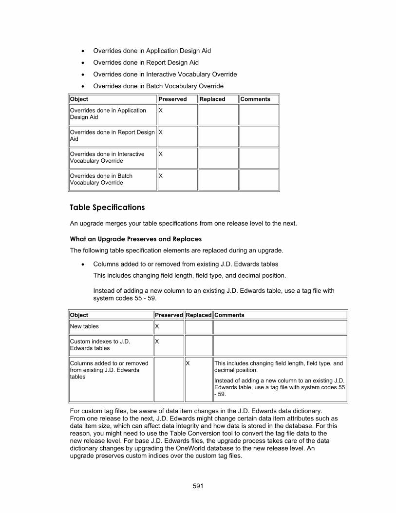
• Overrides done in Application Design Aid
• Overrides done in Report Design Aid
• Overrides done in Interactive Vocabulary Override
• Overrides done in Batch Vocabulary Override
Object Preserved Replaced Comments
Overrides done in Application Design Aid
X
Overrides done in Report Design Aid
X
Overrides done in Interactive Vocabulary Override
X
Overrides done in Batch Vocabulary Override
X
Table Specifications
An upgrade merges your table specifications from one release level to the next.
What an Upgrade Preserves and Replaces The following table specification elements are replaced during an upgrade.
• Columns added to or removed from existing J.D. Edwards tables
This includes changing field length, field type, and decimal position.
Instead of adding a new column to an existing J.D. Edwards table, use a tag file with system codes 55 - 59.
Object Preserved Replaced Comments
New tables X
Custom indexes to J.D. Edwards tables
X
Columns added to or removed from existing J.D. Edwards tables
X This includes changing field length, field type, and decimal position.
Instead of adding a new column to an existing J.D. Edwards table, use a tag file with system codes 55 - 59.
For custom tag files, be aware of data item changes in the J.D. Edwards data dictionary. From one release to the next, J.D. Edwards might change certain data item attributes such as data item size, which can affect data integrity and how data is stored in the database. For this reason, you might need to use the Table Conversion tool to convert the tag file data to the new release level. For base J.D. Edwards files, the upgrade process takes care of the data dictionary changes by upgrading the OneWorld database to the new release level. An upgrade preserves custom indices over the custom tag files.
591

Control Tables
Control tables contain user defined codes (UDCs), menus, and data dictionary items. An upgrade merges your control tables from one release level to the next using the Change Table process, which uses your control tables, not J.D. Edwards tables, as the basis to do the data merge.
What an Upgrade Preserves and Replaces The following control table elements are replaced during an upgrade.
• Columns added or removed from existing J.D. Edwards control tables
Object Preserved Replaced Comments
Data dictionary custom changes
X This includes changes to row, column, and glossary text. The upgrade process uses your data dictionary as the base, and in case of a conflict with J.D. Edwards data items, your changes override. Create new data items using system codes 55 - 59.
User defined codes X The upgrade process merges any new hard-coded J.D. Edwards values. (Values owned by J.D. Edwards are system 90 and above, and H90 and above.) The process also reports any J.D. Edwards hard-coded values that conflict with your custom values.
Menus X In case of a conflict with J.D. Edwards base menus, your custom changes override.
Columns added or removed from existing J.D. Edwards control tables
X
Business Views
Do not remove columns from existing business views. Changing business views that applications use can cause unpredictable results when you run the application. If you need to hide columns, do so at the application design level using either Application Design Aid or Report Design Aid. There is not much of a performance gain by deleting a few columns from a business view.
What an Upgrade Preserves and Replaces The following business view elements are preserved or replaced during an upgrade.
Object Preserved Replaced Comments
New custom business views X
New columns, joins, or indexes added to existing OneWorld business views
X
Columns removed from J.D. Edwards business views.
X
592

Event Rules
What an Upgrade Preserves and Replaces The following event rules elements are preserved or replaced during an upgrade.
Object Preserved Replaced Comments
Custom event rules for custom applications, reports, and tables
X
Custom event rules for custom business functions
X
Custom event rules on a new custom control
X
Events for J.D. Edwards applications, reports, and tables that do not have any J.D. Edwards event rules attached to the same event
X
Events for J.D. Edwards business functions that do not have any J.D. Edwards event rules attached to the same event
X
Events for J.D. Edwards applications, reports, and tables that have existing event rules attached to the same event
X An upgrade disables and appends your custom event rules to the end of the event rules. The merge prints a report (R9840D) to notify you of any event rules that the upgrade process disabled.
Events for J.D. Edwards business functions that have event rules attached to the same event
X An upgrade disables and appends your custom event rules to the end of the event rules. The merge prints a report (R9840D) to notify you of any event rules that the upgrade process disabled.
To restore your custom event rules to J.D. Edwards objects, highlight and drag the event rules back to the proper place in the event and enable them. Prior to an upgrade perform the following:
• Run the Object Librarian Modifications (R9840D) report to identify modified applications
• Print the event rules for the modified application so that you can see the logic behind the event when restoring custom event rules
593
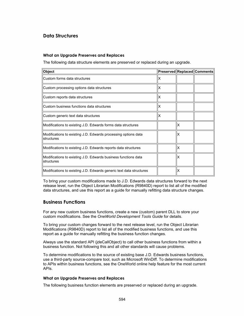
Data Structures
What an Upgrade Preserves and Replaces The following data structure elements are preserved or replaced during an upgrade.
Object Preserved Replaced Comments
Custom forms data structures X
Custom processing options data structures X
Custom reports data structures X
Custom business functions data structures X
Custom generic text data structures X
Modifications to existing J.D. Edwards forms data structures X
Modifications to existing J.D. Edwards processing options data structures
X
Modifications to existing J.D. Edwards reports data structures X
Modifications to existing J.D. Edwards business functions data structures
X
Modifications to existing J.D. Edwards generic text data structures X
To bring your custom modifications made to J.D. Edwards data structures forward to the next release level, run the Object Librarian Modifications (R9840D) report to list all of the modified data structures, and use this report as a guide for manually refitting data structure changes.
Business Functions
For any new custom business functions, create a new (custom) parent DLL to store your custom modifications. See the OneWorld Development Tools Guide for details.
To bring your custom changes forward to the next release level, run the Object Librarian Modifications (R9840D) report to list all of the modified business functions, and use this report as a guide for manually refitting the business function changes.
Always use the standard API (jdeCallObject) to call other business functions from within a business function. Not following this and all other standards will cause problems.
To determine modifications to the source of existing base J.D. Edwards business functions, use a third-party source-compare tool, such as Microsoft WinDiff. To determine modifications to APIs within business functions, see the OneWorld online help feature for the most current APIs.
What an Upgrade Preserves and Replaces The following business function elements are preserved or replaced during an upgrade.
594

Object Preserved Replaced Comments
New custom business function objects X
Modifications made to existing J.D. Edwards business function objects
X NER BSFNs can be modified
Versions
For new custom versions, create a new version with a name that does not begin with XJDE or ZJDE. See the OneWorld Foundation Guide for details.
What an Upgrade Preserves and Replaces The following versions elements are preserved or replaced during an upgrade.
Object Preserved Replaced Comments
Non-JDE versions X
Version specifications X
Processing option data X
All ZJDE and XJDE version specifications X
All processing option data for XJDE versions X
In addition, processing option data is copied but not converted for non-JDE versions using JDE processing option templates. A warning is issued at runtime, and some data may be lost.
Additionally, event rule modifications for custom versions on JDE templates are not reconciled with the JDE parent template.
Form Processing
Processing for the following form types is discussed in this section:
Find/Browse
Parent/Child
Fix/Inspect
Header Detail
Headerless Detail
Search/Select
Message Form
Processing for the following controls is also discussed in this section:
Edit Control
Grid Control
595

Process Flow for Find/Browse Form
A Find/Browse form is used to query a business view and select records from that business view for an operation.
Default Flags There are no form option flags checked by default on Find/Browse forms. The only form option flag that can have an impact for this form type is the "No Fetch on Grid Business View" flag. Checking any of the other form option flags does not have any impact on the form processing.
The Find/Browse forms along with Parent/Child Browse forms are the only forms that have the "Entry Point" property checked by default. Find/Browse forms are typically the entry point into applications. The entry point property can be unchecked by the application developer.
Dialog Initialization 1. Initialize Thread Handling
2. Initialize Error Handling Process
3. Initialize Business View Columns
4. Initialize Form Controls
5. Initialize Grid Fields
6. Initialize Static Text
7. Initialize Helps
8. Initialize Event Rules Structures
9. Create Toolbar
10. Load Form Interconnection data into corresponding business view columns and filter fields, if any
11. Perform Event Rules: Dialog is Initialized
12. Perform Event Rules: Post Dialog is Initialized
13. If the grid option "Automatically Find On Entry" is checked:
14. Begin Detail Data Selection and Sequencing
Header Data Retrieval There is no header record for Find/Browse type forms.
Detail Data Selection and Sequencing An internal structure is created representing the data selection and data sequencing requirements specified by the user. This is then passed to the database engine to do the actual database select and sequencing. The data is then held until the data is retrieved.
The data used for selection is pulled from filter fields and QBE Columns.
596

1. If the form option flag "No Fetch On Grid Business View" is unchecked then the following two actions occur:
Select and Sequence •
• Begin Data Retrieval
2. If the form option flag "No Fetch On Grid Business View" is checked no data retrieval is performed.
Data Retrieval A request is issued to the JDEKRNL, which performs the actual fetch of the data from the database. It will read one record at a time and for each record, perform the following processing:
1. Attempt to fetch a record from the database
2. If a record is fetched
• Copy the data into the business view data structures
• Perform Event Rules: Grid Record is Fetched
• If the application developer has not chosen to suppress the writing of this grid record
• Copy the business view data into the grid data structures
• Perform Event Rules: Write Grid Line - Before
• Add the row to the grid. The row now exists in the grid control
• Perform Event Rules: Write Grid Line - After
• Clear the grid data structures for reading the next record
• Remove the suppress grid line flag
The previous steps occur for each record read from the database. After all records have been read, complete the following:
3. Perform Event Rules: Last Grid Record Has Been Read
Closing Form 1. Perform Event Rules: End Dialog
2 Load Form Interconnection data from corresponding business view columns, if any
3. Terminate Error Handling
4. Terminate Thread Handling
5. Terminate Helps
6. Free all structures for form, including structures for Business View Columns, Form Controls, Grid Columns, and Event Rules
7. Destroy the window
Menu/Toolbar Items
597
Select Select is a standard item that is automatically placed on Find/Browse forms. There is no default processing for Select on Find/Browse forms. It will behave as a user defined item.
Close Close is a standard item that automatically appears on Find/Browse forms. It closes the form.
1. Perform Event Rules: Button Clicked
2.
Find
2. If there no errors in any filter fields:
Perform Event Rules: Post Button Clicked
3. Begin Closing Form
Find is a standard item that automatically appears on Find/Browse forms. When clicked by the user, it is the signal to the runtime engine to call the database and reload the grid based on the selections in the filter fields.
1. Perform Event Rules: Button Clicked
• Begin Data Selection and Sequencing
• Perform Event Rules: Post Button Clicked
Delete Delete is a standard item that can be added to Find/Browse forms. It deletes a record in the grid from the database.
1. Perform Event Rules: Button Clicked
2. For each selected grid row that is deletable
• Copy the grid row data into the Business View structures
• Remove Suppress Delete flag
• Perform Event Rules: Delete Grid Rec Verify - Before
• If the Suppress Delete flag is not set
• Display Delete Confirmation dialog. If the user clicks NO or CANCEL the rest of this processing is skipped.
• Perform Event Rules: Delete Grid Rec Verify - After
• If the Suppress Delete flag is not set
Perform Event Rules: Delete Grid Rec from DB - Before
If the Suppress Delete flag is not set:
• Delete the record in the Business View from the database
• Delete the grid row from the grid control
• Perform Event Rules: Delete Grid Rec from DB - After
3. Perform Event Rules: All Grid Recs Deleted
4. Perform Event Rules: Post Button Clicked
598

Copy Copy is a standard item that can be added to Find/Browse forms. The copy function allows users to duplicate and rename an object. There is no default processing for copy on Find/Browse forms. They will behave as user defined items. If a form Interconnection is placed on the Button Clicked event then the called form will open in copy mode.
Add Add is a standard item that can be added to Find/Browse forms. There is no default processing for add on Find/Browse forms. They will behave as user defined items. If a form Interconnection is placed on the Button Clicked event then the called form will open in add mode.
User Defined Items User-defined items are nonstandard items you can add to Find/Browse forms to perform specialized processing not handled by the standard items.
• Perform Event Rules: Button Clicked
• Perform Event Rules: Post Button Clicked
Process Flow for Parent/Child Browse Form
A Parent/Child form is used to query on a business view and represent the data in a hierarchical manner. Records can also be selected from that business view for an operation. The following sections describe the processing flow of a Parent/Child form type.
Default Flags There are no form options flags checked by default on Parent/Child forms. The only form option flag that can have an impact for this form type is the "No Fetch on Grid Business View" flag. Checking any of the other form option flags does not have any impact on the form processing.
The Parent/Child Browse forms along with Find/Browse forms are the only forms that have the "Entry Point" property checked by default. Parent/Child forms are typically the entry points into applications. The entry point property can be unchecked by the application developer.
2. Initialize Error Handling Process
Dialog Initialization 1. Initialize Thread Handling
3. Initialize Business View Columns
4. Initialize Form Controls
5. Initialize Grid/Tree Fields
6. Initialize Static Text
7. Initialize Helps
8. Initialize Event Rules Structures
9. Create Toolbar
10. Load Form Interconnection data into corresponding business view columns and filter fields, if any
11. Perform Event Rules: Dialog is Initialized
599

12. Perform Event Rules: Post Dialog is Initialized
13.
•
If the grid option flag "Automatically Find On Entry" is checked
• Begin Detail Data Selection and Sequencing
Header Data Retrieval There is no header record for Parent/Child forms.
Detail Data Selection and Sequencing An internal structure is now created representing the data selection and data sequencing requirements specified by the user. This is then passed to the database engine to do the actual database select and sequencing. The data is then held until the data is retrieved in the next step.
The data used for selection is pulled from filter fields and QBE Columns.
1. If the form option flag "No Fetch On Grid Business View" is unchecked
Select and Sequence
• Begin Data Retrieval
Data Retrieval A request is issued to the JDEKRNL, which performs the actual fetch of the data from the database. It reads one record at a time and for each record, perform the required processing. The data retrieval is performed in two different ways in the Parent/Child browse form. The fetch performed to get the first level nodes in the tree is similar to the one performed in the Find/Browse form:
Data Retrieval for the first level node in the tree 1. Attempt to fetch a record from the database
2. If a record is fetched
• Copy the data into the business view data structures
• Perform Event Rules: Grid Record is Fetched
• If the application developer has not chosen to suppress the writing of this record
• Copy the business view data into the grid data structures
• Perform Event Rules: Write Grid Line - Before
• Add the row to the grid and the corresponding column in Tree. The row and the corresponding tree node now exist in the control.
• Perform Event Rules: Write Grid Line - After
• Clear the data structures for reading the next record.
The previous steps occur for each record read from the database. After all records have been read:
1. If the Parent/Child Browse form has the grid permanently hidden, then expand the header node and move the selection to the first child node under the header. This initiates the events: `Tree - Node Level Changed' and `Tree - Node Selection Changed.'
2. Perform Event Rules: Last Grid Record Has Been Read
600
The Parent/Child form also performs data retrieval whenever a particular node on the tree is expanded. However, this fetch is performed only once for each node that is expanded. If a particular node is collapsed and expanded again, then the tree and the grid are replenished from internal structures. The processing performed for node expand event is given below:
Data Retrieval for Tree Node Expand 1. Perform Event Rules: Tree - Node is expanding
2. Check for internal flags to see if the fetch is not suppressed. If the fetch is suppressed through the system function, Suppress Fetch on Node Expand, the processing stops here.
3. Perform the key substitution (copying child key into parent key), that was setup in the design of the form.
4. Attempt to fetch a record from the database
5. If a record is fetched
• Copy the data into the business view data structures
• Perform Event Rules: Grid Record is Fetched
• If the application developer has not chosen to suppress the writing of this record
• Copy the business view data into the grid data structures
• Perform Event Rules: Write Grid Line - Before
• Add the row to the grid and the corresponding column in Tree. The row and the corresponding tree node now exist in the control.
• Perform Event Rules: Write Grid Line - After
• Clear the data structures for reading the next record.
6. Perform Event Rules: Last Grid Record Has Been Read
7. Move the tree selection to the first child node under the expanding node. This initiates the Events: Tree - Node Level Changed and Tree - Node Selection Changed.
Closing Form 1. Perform Event Rules: End Dialog
2. Load Form Interconnection data from corresponding business view columns, if any
3. Terminate Error Handling
4. Terminate Thread Handling
5. Terminate Helps
6. Free all structures for form, including structures for Business View Columns, Form Controls, Grid Columns, and Event Rules.
7. Destroy the window
Menu/Toolbar Items The following is the process flow for the menu/toolbar items on a Parent Child Form.
601

Select Select is a standard item that is automatically placed on Parent/Child Browse forms. There is no default processing for Select on Parent/Child Browse forms. It will behave as a user-defined item.
Close Close is a standard item that automatically appears on Parent/Child Browse forms. It closes the form.
1. Perform Event Rules: Button Clicked
2.
Display Delete Confirmation dialog. If the user clicks No or Cancel the rest of this processing is skipped.
Perform Event Rules: Post Button Clicked
3. Begin Closing Form
Delete Delete is a standard item that can be added to Parent/Child Browse forms. Similar to the Find/Browse form, the Parent/Child Browse form does the following.
1. Perform Event Rules: Button Clicked
2. For the selected tree node
• Copy the grid row data into the Business View structures
• Remove Suppress Delete flag
• Perform Event Rules: Delete Grid Rec Verify - Before
• If the Suppress Delete flag is not set
Perform Event Rules: Delete Grid Rec Verify - After
If the Suppress Delete flag is not set
• Perform Event Rules: Delete Grid Rec from DB - Before
• If the Suppress Delete flag is not set
Delete the record in the Business View from the database.
This will not delete the child records of the node, if any, from the database. It is your responsibility to delete them from the database.
Delete the grid row from the grid control
Perform Event Rules: Delete Grid Rec from DB - After
3. Perform Event Rules: All Grid Recs Deleted
4. Perform Event Rules: Post Button Clicked
Find Find is a standard item that automatically appears on Parent/Child Browse forms. When clicked by the user, it is the signal to the runtime engine to call the database and reload the grid based on the selections in the Filter Fields and QBE columns.
602

1. Perform Event Rules: Button Clicked
2. If there no errors in any filter fields
• Begin Data Selection and Sequencing
• Perform Event Rules: Post Button Clicked
Copy Copy is a standard item that can be added to Parent/Child Browse forms. There is no default processing for copy on Parent/Child Browse forms. The forms work as user defined items. If a form interconnection is placed on the Button Clicked event then the called form will open in copy mode.
Add Add is a standard item that can be added to Parent/Child forms. There is no default processing for add on Parent/Child forms. The forms work as user defined items. If a form interconnection is placed on the Button Clicked event then the called form will open in add mode.
User-Defined Items User-defined items are nonstandard items that you can add to Parent/Child forms to perform specialized processing not handled by the standard items.
1. Perform Event Rules: Button Clicked
2. Perform Event Rules: Post Button Clicked
Process Flow for Fix/Inspect Form
A Fix/Inspect form is used to update and insert single data base records. It is also referred to as a Single Record Maintenance form. This form type can also be used to display static information to the user as well as prompt the user for information. For example, a Sign-on Screen prompts the user to sign on to OneWorld. The following sections describe the processing flow of a Fix/Inspect form type.
Default Flags None of the form option flags are set by default.
Dialog Initialization 1. Initialize Thread Handling
2. Initialize Error Handling Process
3. Initialize Business View Columns
4. Initialize Form Controls
5. Initialize Static Text
6. Initialize Helps
7. Initialize Event Rules Structures
8. Create Toolbar
9. Load Form Interconnection data into corresponding business view columns. (Note: Form controls and business view columns are sharing internal memory so copying
603

into the business view is effectively copying into the internal form control memory locations.)
10. Perform Event Rules: Dialog is Initialized
11. If the No Fetch Form Business View is checked
• Perform Event Rules: Post Dialog is Initialized
12. If the form is in Add Mode
• Begin Clearing Dialog
13. If the form is in update mode and No Fetch Form Business View is checked
• Change mode to add mode
• Display the internal form control values to the screen
• Begin Clearing Dialog
14. If the form is in update mode and No Fetch Form Business View is not checked
• Begin Data Retrieval
Data Retrieval A request is issued to the JDEKRNL, which performs the actual fetch of the data from the database. The fetch is based on the information passed to the form through its form data structure.
1. Attempt to fetch a record from the database
2. If a record is fetched
• Copy the data into the business view data structures (Note: remember that copying into the business view is effectively copying into the internal form control memory locations.)
3. If a record is found and the form is in Copy Mode
• Switch to Add Mode
Display the internal form control values to the screen •
• Begin Clearing Dialog
4. If a record is found and not in Copy mode.
• Perform Event Rules: Post Dialog is Initialized
5. If no records were fetched
• Switch to Add Mode.
• Display the internal form control values to the screen
• Begin Clearing Dialog
6. Set the default focus based on the resulting data base mode
Clearing Dialog 1. If the form was called in Copy Mode
• Clear the key (primary index) controls that have the "Do Not Clear After Add" flag unchecked
2. If the form was not called in Copy Mode
604

• Clear all form controls that have the "Do Not Clear After Add" flag unchecked
3. Perform Event Rules: Clear Screen Before Add
4. Perform Event Rules: Post Dialog is Initialized
Closing Form 1. Perform Event Rules: End Dialog
2. Load Form Interconnection data from corresponding business view columns, if any
3. Terminate Error Handling
4. Terminate Thread Handling
5. Terminate Helps
6. Free all structures for form, including structures for Business View Columns, Form Controls, and Event Rules.
7. Destroy the window
Menu/Toolbar Items The following is the process flow for the menu/toolbar items on a Fix/Inspect Form.
OK OK is a standard item that is automatically placed on Fix/Inspect forms. It validates the information on the form and updates or adds to the database through JDEKRNL function calls.
1. If there are any errors/warnings on the form, stop OK processing
2. Perform Event Rules: Button Clicked
3. For each control on the form
• If the current control is a form control and it has not passed validation
• Perform Event Rules: Control is Exited
• Perform Event Rules: Control is Exited and Changed - Inline
• Perform Event Rules: Control is Exited and Changed - Async
• Perform Data Dictionary validation
4. If there are any errors on the form, stop OK processing
5. If the form is in Add mode
• Perform Event Rules: Add Record to Database - Before
6. If the form is in Update mode
• Perform Event Rules: Update Record to Database - Before
7. Perform Event Rules: Post Button Clicked
8. If form is in Add Mode
• If form was called in Copy Mode or the flag `End Form On Add' is checked
• Begin Closing Form
• Else
• Begin Clearing Dialog
605

9. If the form is in Update Mode
• If there were no errors attempting to update/add to the database
• Begin Closing Form
Cancel Cancel is a standard item that is automatically placed on Fix/Inspect forms.
1. Perform Event Rules: Button Clicked
2. Perform Event Rules: Post Button Clicked
3. Begin Closing Form
User-Defined Items User-defined items are non-standard items that a developer can add to Fix/Inspect forms to perform specialized processing not handled by the standard items.
1. Perform Event Rules: Button Clicked
2. Perform Event Rules: Post Button Clicked
Process Flow for Header Detail Form
A Header Detail form is used when a relationship exists between the information in the header and the information in the detail area. The Header portion uses one business view, and the detail portion of the form uses another business view. This form type and the Headerless Detail form type are referred to as Transaction forms. The following sections describe the processing flow of a Header Detail form type.
Default Flags No form option flags are automatically set for this form type. All form option flags can be checked or unchecked by the application developer.
Dialog Initialization 1. Initialize Thread Handling
2. Initialize Error Handling Process
3. Initialize Business View Columns
4. Initialize Form Controls
5. Initialize Grid Fields
6. Initialize Static Text
7. Initialize Helps
8. Initialize Event Rules Structures
9. Create Toolbar
10. Load Form Interconnection data into corresponding business view columns and filter fields, if any
11. Perform Event Rules: Dialog is Initialized
12. If the form option flag "No Fetch On Form Business View" is checked
• If the form is not in Add mode and was not entered with a Copy button
606

• Perform Event Rules: Post Dialog is Initialized
• Copy the Form Control values to the screen
13. If the form is in Update mode (note that this includes forms entered with a Copy button)
• If the form option flag "No Fetch On Form Business View" is checked
• Begin Detail Data Selection and Sequencing
• If the form option flag "No Fetch On Form Business View" is unchecked
• Begin Header Data Retrieval
14. If the form is in Add Mode
• Begin Clearing Dialog
Header Data Retrieval A key structure is built for the business view of the header based on the header Business View Columns, or from the filter fields, if any exist. Then a call is made to the database attempting to retrieve the record specified.
1. If the database fetch is successful
• Copy the fetched database record to the header Business View Columns
• If the form was not opened with a Copy button
• Perform Event Rules: Post Dialog is Initialized (note that where form controls and business view columns share memory, the form controls will have the values from the database during this event, which may mean blanks in the case of strings and characters)
• Copy the Business View Columns to the Form Controls
• If the grid option "Automatically Find on Entry" is checked
• Begin Detail Data Selection and Sequencing
• If the grid option "Automatically Find on Entry" is unchecked
• Begin Add Entry to Row to Grid
2. If the database fetch failed
• Begin Clearing Dialog.
Detail Data Selection and Sequencing An internal structure is now created representing the data selection and data sequencing requirements specified by the user for the detail portion. This is then passed to the database engine to do the actual database select and sequencing. The data is retrieved in the next step.
The data used for selection comes from filter fields, if any exist, or from the key business view columns, if no filter fields exist.
1. If the form option flag "No Fetch On Grid Business View" is unchecked
Select and Sequence •
• Begin Data Retrieval
2. If the form option flag `No Fetch On Grid Business View' is checked
607

3. Begin Add Entry Row To Grid.
Data Retrieval A request is issued to the JDEKRNL, which performs the actual fetch of the data from the database. It will read one record at a time and for each record, perform the following processing:
1. Attempt to fetch a detail record from the database
2. If a record is fetched
• Copy the data into the detail business view data structures
• Perform Event Rules: Grid Record is Fetched
• If the application developer has not chosen to suppress the writing of this grid record
• Copy the business view data into the grid data structures
• Perform Event Rules: Write Everest Grid Line - Before
• Add the row to the grid. The row now exists in the grid control.
• Perform Event Rules: Write Everest Grid Line - After
• Clear the grid data structures for reading the next record.
• Remove the suppress grid line flag.
The previous steps occur for each record read from the database. After all records have been read, the runtime engine will then:
1. If the form was opened with a Copy button
• Switch to Add Mode
• Begin Clearing Dialog once Detail Data Retrieval processing is complete
2. If no records were fetched
• Switch to Add Mode
3. Perform Event Rules: Last Grid Record Has Been Read (note that this event is run regardless if records were actually fetched)
4. Begin Add Entry Row to Grid.
Clearing Dialog 1. If the form was called in Copy Mode
• Clear the key controls that have the "Do Not Clear After Add" flag unchecked
2. If the form was not called in Copy Mode
• Clear all form controls that have the "Do Not Clear After Add" flag unchecked
3. Perform Event Rules: Clear Screen Before Add
4. Delete any existing rows
5. Perform Event Rules: Post Dialog is Initialized
6. Begin Add Entry Row to Grid
Add Entry Row to Grid 1. Clear grid data structures
608

2. Perform Event Rules: Add Last Entry Row to Grid
3. Add the row to the grid control
Closing Form 1. Perform Event Rules: End Dialog
2. Load Form Interconnection data from corresponding business view columns, if any
3. Terminate Error Handling
4. Terminate Thread Handling
5. Terminate Helps
6. Free all structures for form, including structures for Business View Columns, Form Controls, Grid Columns, and Event Rules.
7. Destroy the window
Menu/Toolbar Items
OK
• Perform Event Rules: Control is Exited and Changed - Inline
• Perform Event Rules: Control is Exited and Changed - Asynch
Perform Event Rules: Row is Exited and Changed - Asynch for current row
5. Delete from the database any grid rows that are in the delete stack. See Delete for details. For each grid row in the delete stack:
The following is the process flow for the menu/toolbar items on a Header Detail Form.
OK is a standard item that is automatically placed on header detail forms. It validates the information on the form and updates or adds to the database through JDEKRNL function calls.
1. If there are any errors/warnings on the form, stop OK processing.
2. Perform Event Rules: Button Clicked
3. For each control on the form
• If the current control is a form control and it has not passed validation
• Perform Event Rules: Control is Exited
• Perform Data Dictionary validation
• If the current control is a grid control
• For each grid row
If the current grid row needs to have Leave Row processing run and the row is updatable
Perform Event Rules: Row is Exited and Changed - Inline for current row
4. If there are any errors on the form, stop OK processing
• Copy the information from the delete stack into the grid data structures
• Copy the grid data structures into the Business View structures
• Perform Event Rules: Delete Grid Record from DB - Before
609
• If the database delete has not been suppressed
a. Delete the record in the Business View from the database
b. Delete the grid row from the grid control
c. Perform Event Rules: Delete Grid Record from DB - After
6. Perform Event Rules: All Grid Recs Deleted from DB
7. If the form option flag `No Update On Form Business View' is unchecked
• If the form is in Add mode
• Perform Event Rules: Add Record to Database - Before
• If the database add has not been suppressed
Add the header business view record to the database
• Perform Event Rules: Add Record to Database - After
• If the form is in Update mode
• Perform Event Rules: Update Record to Database - Before
• If the database Update has not been suppressed
Update the record to the database
Perform Event Rules: Update Record to Database - After
8. If the form option flag `No Update On Grid Business View' is unchecked
• For each grid row that was changed or added
• Clear the business view data structures
• Reset the original key values for this row in the business view data structures
• Copy grid data structures to the business view data structures
• Copy all non-filter database form controls to the business view data structures
• Copy all equal filters to the business view data structures
• If form is in Add Mode
Perform Event Rules: Add Grid Rec to DB - Before
Add the record in the business view data structure to the database
Perform Event Rules: Add Grid Rec to DB - After
• If form is in Update Mode
Perform Event Rules: Update Grid Rec to DB - Before
• Perform Event Rules: All Grid Recs Added to DB
Update the record in the business view data structure to the database
Perform Event Rules: Update Grid Rec to DB - After
• If form is in Add Mode
610

• If form is in Update Mode
• Perform Event Rules: All Grid Recs Updated to DB
9. Perform Event Rules: Post Button Clicked
10. If form is in Add Mode
• If form was called in Copy Mode or the flag `End Form On Add' is checked
• Begin Closing Form
• Else
• Begin Clearing Dialog
11. If the form is in Update Mode
• If there were no errors attempting to update/add to the database
• Begin Closing Form
Cancel Cancel is a standard item that is automatically placed on header detail forms.
1. Perform Event Rules: Button Clicked
2.
• Delete the grid row from the grid control
Perform Event Rules: Post Button Clicked
3. Begin Closing Form
Delete Delete is a standard item that can be added to Header Detail forms. The delete applies to the grid record(s) selected. The actual delete from the database does not happen at this point, so that if the user clicks cancel, the records are not deleted from the database. The delete verification happens when the delete is pressed, and the actual database delete happens when OK is pressed.
1. Perform Event Rules: Button Clicked
2. For each selected grid row that is deletable
• Remove Suppress Delete flag
• Perform Event Rules: Delete Grid Rec Verify - Before
• If the Suppress Delete flag is not set
Display Delete Confirmation dialog. If the user clicks NO or CANCEL the rest of this processing is skipped
Perform Event Rules: Delete Grid Rec Verify - After
If the Suppress Delete flag is not set
• If the record was read from the database
Add this record to the delete stack (records to be deleted if the user presses OK)
611

Find Find is a standard item that can be added to header detail forms. When clicked by the user, it is the signal to the runtime engine to call the database and reload the grid based on the selections in the filter fields.
1. Perform Event Rules: Button Clicked
2. If there no errors in any filter fields
•
Begin Detail Data Selection and Sequencing
Switch to Update Mode
•
• Perform Event Rules: Post Button Clicked
User-Defined Items User-defined items are non-standard items that a developer can add to Header Detail forms to perform specialized processing not handled by the standard items.
1. Perform Event Rules: Button Clicked
2. Perform Event Rules: Post Button Clicked
Process Flow for Headerless Detail Form
A Headerless Detail form is used to update and enter records that have information that is common to all records in a selected group. This form type and the Header Detail form type are referred to as Transaction forms. The following sections describe the processing flow of a Headerless Detail form type.
Default Flags The following form option flags are automatically checked for Headerless Detail Forms and should not be unchecked:
• No Update On Form Business View
• No Fetch On Form Business View
Other form option flags can be checked or unchecked by the application developer.
Dialog Initialization 1. Initialize Thread Handling
2. Initialize Error Handling Process
3. Initialize Business View Columns
4. Initialize Form Controls
5. Initialize Grid Fields
6. Initialize Static Text
7. Initialize Helps
8. Initialize Event Rules Structures
9. Create Toolbar
10. Load Form Interconnection data into corresponding business view columns and filter fields, if any
11. Perform Event Rules: Dialog is Initialized
612

12. If the form is not in Add Mode
• If the form is not in Copy Mode
• Perform Event Rules: Post Dialog is Initialized (note that this event is run immediately after Dialog is Initialized when in Update mode, so the FC values are still at their NULL or zero value)
• If the grid option "Automatically Find on Entry" is checked
• Begin Data Selection and Sequencing
• If the grid option "Automatically Find on Entry" is unchecked
• Begin Add Entry Row to Grid
• If the form is in Add Mode
• Begin Clearing Dialog
Data Selection and Sequencing An internal structure is now created representing the data selection and data sequencing requirements specified by the user. This is then passed to the database engine to do the actual database select and sequencing. The data is then held until the data is retrieved in the next step.
The data used for selection is pulled from filter fields if any exist, or from the key business view columns if there are no filter fields.
1. If the form option flag "No Fetch On Grid Business View" is unchecked
Select and Sequence •
• Begin Data Retrieval
2. If the form option flag "No Fetch On Grid Business View" is checked
• Begin Add Entry Row To Grid
Data Retrieval A request is issued to the JDEKRNL, which performs the actual fetch of the data from the database. It will read one record at a time and for each record, perform the following processing:
1. Attempt to fetch a record from the database
2. If a record is fetched
• Copy the data into the business view data structures
• Perform Event Rules: Grid Record is Fetched
• If the application developer has not chosen to suppress the writing of this grid record
• Copy the business view data into the grid data structures
• Perform Event Rules: Write Grid Line - Before
• Add the row to the grid. The row now exists in the grid control.
• Perform Event Rules: Write Grid Line - After
• Clear the grid data structures for reading the next record.
• Remove the suppress grid line flag.
613
The previous steps occur for each record read from the database. After all records have been read, the runtime engine will then:
1. If the form is in Copy Mode
• Switch to Add Mode
• Begin Clearing Dialog once Data Retrieval processing is complete
2. If no records were fetched
• Switch to Add Mode
3. Perform Event Rules: Last Grid Record Has Been Read (note that this event is run regardless of whether records were actually fetched)
4.
Add Entry Row to Grid
4. Begin Add Entry Row to Grid.
Clearing Dialog 1. If the form was called in Copy Mode
• Clear the key controls that have the "Do Not Clear After Add" flag unchecked
2. If the form was not called in Copy Mode
• Clear all form controls that have the "Do Not Clear After Add" flag unchecked
3. Perform Event Rules: Clear Screen Before Add
• Delete any existing grid rows
Perform Event Rules: Post Dialog is Initialized
• Begin Add Entry Row to Grid
1. Clear grid data structures
2. Perform Event Rules: Add Last Entry Row to Grid
3. Add the row to the grid control
Closing Form 1. Perform Event Rules: End Dialog
2. Load Form Interconnection data from corresponding business view columns, if any
3. Terminate Error Handling
4. Terminate Thread Handling
5. Terminate Helps
6. Free all structures for form, including structures for Business View Columns, Form Controls, Grid Columns, and Event Rules
7. Destroy the window
Menu/Toolbar Items The following is the process flow for the menu/toolbar items on a Headerless Detail Form.
614

OK OK is a standard item that is automatically placed on Headerless Detail forms. It validates the information on the form and updates or adds to the database through JDEKRNL function calls.
1. If there are any errors/warnings on the form, stop OK processing
2. Perform Event Rules: Button Clicked
3. For each control on the form
• If the current control is a form control and it has not passed validation
• Perform Event Rules: Control is Exited
• Perform Event Rules: Control is Exited and Changed - Inline
• Perform Event Rules: Control is Exited and Changed - Asynch
• Perform Data Dictionary validation
• If the current control is a grid control, perform the following for each grid row:
• Perform Event Rules: Row is Exited and Changed - Inline for current row
• Perform Event Rules: Row is Exited and Changed - Asynch for current row
4. If there are any errors on the form, stop OK processing
5. Delete from the database any grid rows that are in the delete stack. See Delete for details. For each grid row in the delete stack:
• Copy the grid row data into the Business View structures
• Copy the grid data structures into the business view data structures
• Perform Event Rules: Delete Grid Record from DB - Before
• If the database delete has not been suppressed
• Delete the record in the Business View from the database
• Delete the grid row from the grid control
• Perform Event Rules: Delete Grid Record from DB - After
6. Perform Event Rules: All Grid Recs Deleted from DB
7. If the form option flag `No Update On Grid Business View' is unchecked
• For each grid row that was changed or added
• Clear the business view data structures
• Reset the original key values for this row in the business view data structures
• Copy grid data structures to the business view data structures
• Copy all non-filter database form controls to the business view data structures
• Copy all equal filters to the business view data structures
• If form is in Add Mode
Perform Event Rules: Add Grid Rec to DB - Before
Add the record in the business view data structure to the database
Perform Event Rules: Add Grid Rec to DB - After
615

• If form is in Update Mode
Perform Event Rules: Update Grid Rec to DB - Before
Update the record in the business view data structure to the database
Perform Event Rules: Update Grid Rec to DB - After
• If form is in Add Mode
• Perform Event Rules: All Grid Recs Added to DB
• If form is in Update Mode
• Perform Event Rules: All Grid Recs Updated to DB
8. Perform Event Rules: Post Button Clicked
9. If form is in Add Mode
• If form was called in Copy Mode or the flag `End Form On Add' is checked
• Begin Closing Form
• Else
• Begin Clearing Dialog
10. If the form is in Update Mode
• If there were no errors attempting to update/add to the database
• Begin Closing Form
Cancel Cancel is a standard item that is automatically placed on Headerless Detail forms.
1. Perform Event Rules: Button Clicked
2. Perform Event Rules: Post Button Clicked
3. Begin Closing Form
Delete Delete is a standard item that can be added to Headerless Detail forms. The actual delete from the database does not happen at this point, so that if the user clicks cancel, the records are not deleted from the database. The delete verification happens when delete is pressed, and the actual database delete happens when OK is pressed.
1. Perform Event Rules: Button Clicked
2. For each selected grid row that is deletable
• Remove Suppress Delete flag
• Perform Event Rules: Delete Grid Rec Verify - Before
• If the Suppress Delete flag is not set
• Display Delete Confirmation dialog. If the user clicks No or Cancel, the rest of this processing is skipped.
• Perform Event Rules: Delete Grid Rec Verify - After
• If the Suppress Delete flag is not set
616

• If the record was read from the database
• Add this record to the delete stack (records to be deleted if the user presses OK)
• Delete the grid row from the grid control
Find Find is a standard item that can be added to Headerless Detail forms. When clicked by the user, it is the signal to the runtime engine to call the database and reload the grid based on the selections in the Filter Fields.
1. Perform Event Rules: Button Clicked
2. If there no errors in any filter fields
Switch to Update Mode •
• Begin Data Selection and Sequencing
• Perform Event Rules: Post Button Clicked
User-Defined Items User-defined items are non-standard items that a developer can add to Headerless Detail forms to perform specialized processing not handled by the standard items.
1. Perform Event Rules: Button Clicked
2. Perform Event Rules: Post Button Clicked
Process Flow for Search/Select Form
A Search/Select form is used to select a single predetermined field from a record in a predetermined file.
Important Search/Select forms return only one value to the calling form, based on the dictionary alias. If no data dictionary alias matches the value, the first value from the data structure will be returned.
The following sections describe the processing flow of a Search/Select form type. A Search/Select form should be attached as a visual assist only to data items that have the same data type as the form data structure element.
Default Flags No form option flags are automatically set for this form type, but application developers often check the Grid option flag called Automatically Find on Entry. The only form option flag that this form type affects is the No Fetch on Grid Business View flag. Checking any of the other form option flags does not affect form processing.
Dialog Initialization 1. Initialize Thread Handling
2. Initialize Error Handling Process
3. Initialize Business View Columns
617

4. Initialize Form Controls
5. Initialize Grid Fields
6. Initialize Static Text
7. Initialize Helps
8. Initialize Event Rules Structures
9. Create Toolbar
10. Load Form Interconnection data into corresponding business view columns and filter fields, if any
11. Perform Event Rules: Dialog is Initialized
12. Perform Event Rules: Post Dialog is Initialized
13.
•
If the grid option "Automatically Find On Entry' is checked
• Begin Detail Data Selection and Sequencing
Header Data Retrieval There is no header record on Search/Select Forms.
Detail Data Selection and Sequencing An internal structure is now created representing the data selection and data sequencing requirements specified by the user. This is then passed to the database engine to do the actual database select and sequencing. The data is then held until the data is retrieved in the next step.
The data used for selection is pulled from filter fields.
1. If the form option flag "No Fetch On Grid Business View" is unchecked
Select and Sequence
• Begin Data Retrieval
Data Retrieval A request is issued to the JDEKRNL, which performs the actual fetch of the data from the database. It reads one record at a time, and, for each record, performs the following processing:
1. Attempt to fetch a record from the database
2. If a record is fetched
• Copy the data into the business view data structures
• Perform Event Rules: Grid Record is Fetched
• If the application developer has not chosen to suppress the writing of this grid record
• Copy the business view data into the grid data structures
• Perform Event Rules: Write Grid Line - Before
• Add the row to the grid. The row now exists in the grid control
• Perform Event Rules: Write Grid Line - After
• Clear the grid data structures for reading the next record
618

• Remove the suppress grid line flag
The previous steps occur for each record read from the database. The following occurs only once.
• Perform Event Rules: Last Grid Record Has Been Read
Clearing Dialog Not done for this form type.
Closing Form 1. Perform Event Rules: End Dialog
2. Load Form Interconnection data from corresponding business view columns, if any
3. Terminate Error Handling
4. Terminate Helps
5. Free all structures for form, including structures for Business View Columns, Form Controls, Grid Columns, and Event Rules
6. Destroy the window
Menu/Toolbar Items The following is the process flow for the menu/toolbar items on a Search/Select Form.
Select Select is a standard item that is automatically placed on Search/Select forms. It returns a value to the form interconnection and closes the form.
1. Copy the selected grid row into the business view column
2. Perform Event Rules: Button Clicked
3.
2.
1.
Perform Event Rules: Post Button Clicked
4. Begin Closing Form
Close Close is a standard item that is automatically placed on Search/Select forms.
1. Perform Event Rules: Button Clicked
Perform Event Rules: Post Button Clicked
3. Begin Closing Form
Find Find is a standard item that can be added to Search/Select forms. When clicked by the user, it is the signal to the runtime engine to call the database and reload the grid based on the selections in the Filter Fields.
Perform Event Rules: Button Clicked
2. Begin Data Selection and Sequencing
3. Perform Event Rules: Post Button Clicked
619

User-Defined Items User-defined items are non-standard items that a developer can add to Search/Select forms to perform specialized processing not handled by the standard buttons.
1. Perform Event Rules: Button Clicked
2. Perform Event Rules: Post Button Clicked
Process Flow for Message Form
The Message form type is a form that appears as a secondary window to inform the user of something or to ask a question. It parallels the behavior of a Windows message box. The form does not have a toolbar or a status bar and can only contain static text and buttons. It is the only form type for which standard buttons can appear on the form instead of the toolbar.
Dialog Initialization 1. Initialize Form Controls
2. Initialize Static Text
3. Initialize Helps
4. Initialize Event Rules Structures
5. Perform Event Rules: Dialog is Initialized
Closing Form 1. Terminate Helps
2. Free all structures for Controls and Event Rules
3. Destroy the window
Buttons The form includes an OK button by default. Other options include Cancel, Yes, and No. All of these buttons cause the dialog to close, and there is no other default processing.
J.D. Edwards Standards These forms may only have static text and buttons. Event rules are limited to only Dialog is Initialized and any button events. This event rule may not contain any Form Interconnection calls.
Process Flow for Edit Control
An edit control is a text field on a form. All form types can contain edit controls except Message forms. There are two types of edit controls. The first type is commonly referred to as a database field. It is associated with an item in the business view and through that connection to a dictionary item. Database fields represent a field in a database record. The second type of edit control is commonly referred to as a data dictionary field. Although only one type is called a data dictionary field, both types have a connection to a specific data dictionary item.
Within the realm of database fields there is an added distinction between filter fields and non-filter fields. Database fields are nonfilter fields by default. A filter field is used to alter the selection criteria of a database fetch. A filter can have a comparison type of equal, not equal,
620

less than, less than or equal to, greater than, or greater than or equal to. A filter can be marked so that a wildcard (*) displays when the filter is not included in the selection.
The actual storage for the value of the edit control is based on the type of the associated dictionary item (such as numeric, string, character) and is distinct from the screen representation of the value. An edit control is affected by the properties of the associated dictionary item. For example, if an edit control is associated with a dictionary item of type string with a length of thirty, that edit control will not allow more than thirty characters to be typed into the field.
Properties and Options The following properties and options are available for edit controls. These properties are available on all form types and for both database fields and data dictionary fields. Only those properties that affect processing are discussed here. Those properties that are exclusively interface-related are either not discussed, or are only discussed as they relate to control processing.
Disable Controls with this property appear gray and cannot be changed by the user. You can use event rules to change the value of disabled fields. When a control is disabled, the associated text (static text to the left) is also disabled. Controls do not have this property by default.
Visible Controls with this property can be seen. Without this property the control cannot be seen. You can use event rules to change the value of hidden controls.
Do not clear after add
This option applies only when a form is in add mode and the form is being cleared. Controls with this option retain their value. Controls do not have this option by default.
Required entry field
This option requires that a value is entered in the control before the record is saved (OK processing). This option does not accept either Null or blank. Controls do not have this option by default.
Default cursor on add/update mode
This option specifies where the cursor will be placed in add/update mode. If multiple controls have this property on, you cannot predict which control will actually have the cursor. Controls do not have this option by default.
No display if currency is Off
This option causes the control to be hidden when the Multicurrency Conversion is off. Controls do not have this option by default.
Control is Entered 1.Perform event rules: Control is Entered
On a Windows client, when a user presses the tab key or otherwise causes focus to move from one control to another, the control that receives focus actually receives the Control is Entered message before the control that loses focus receives the Control is Exited message. Because this is a direct result of the sequence of Windows messages, it cannot be altered.
Control is Exited 1. If the focus is going to another window, stop processing. (Focus will return to this
control when this window again receives focus.)
2. Copy the text from the screen to the internal storage. (Conversion from string to the appropriate type happens during this step.)
3. If this control is marked as a required entry field and does not contain a value, then set the field in error.
621
4. Perform event rules: Control is Exited.
5. If this is the first time this control has been exited, or if this control has changed in value since the last time the control was exited, then complete the following:
• Begin Control is Exited and Changed (Inline)
Control is Exited and Changed (Inline portion) 1. Perform event rules: Control is Exited and Changed Inline
2. If the form is not closing:
• Attempt to execute Control is Exited and Changed (Asynchronous) on a thread.
3. If the form is closing or if the attempt to execute asynchronously was unsuccessful:
• Begin Control is Excited and Changed (Asynchronous) as an inline function.
Control is Exited and Changed (Asynchronous portion) 1. Perform event rules: Control is Exited and Changed Asynch
2. If no errors were set during event rules processing
• If this is not a filter field, or if it is an equal filter field (validation takes place only on filter fields with a comparison type of equal):
• Perform Data Dictionary Validation
• If there is an associated description for this control, populate it (if there were errors, this clears the associated description)
• If there were no errors during validation, then copy the value to the control
J.D. Edwards Standards All filter fields are marked with Display Wildcard. Only index fields are marked as filter fields (for performance). If reasonable, event rule should be put on Control is Exited and Changed Asynch instead of on one of the inline events (for performance).
Process Flow for Grid Control
A grid control is similar to a spreadsheet on a form. Find/Browse, Search and Select, Header Detail, and Headerless Detail form types can contain grid controls. Grid controls contain columns. The columns are specified at design time. There are two types of columns. The first type is commonly referred to as a database column. It is associated with an item in the business view and through that connection to a dictionary item. Database columns represent a field in a database record. The second type of column is commonly referred to as a data dictionary column. Although only one type is called a data dictionary column, both types have a connection to a specific data dictionary item. The difference is that a database column has the additional connection to a business view field.
A grid can either be a browse grid or an update grid. You can use a browse grid for viewing only, and cells cannot be selected individually. The Find/Browse form and the Search and Select form have browse grids. You can use an update grid to add or update records. Cells in an update grid can be selected individually. The Header Detail form and the Headerless Detail form have update grids.
Grid controls can also have a Query By Example (QBE) line. The QBE columns have a one-to-one correspondence with the grid columns. You use a QBE value to change the selection criteria of a database fetch. Only database columns allow entry in the QBE columns because
622
the purpose of the QBE is to affect the select and only database columns are in the business view. A QBE column can have one of the following comparison types:
• equal
• not equal
• less than
• less than or equal to
• greater than
• greater than or equal to
The comparison type is equal unless you specify otherwise. You can specify the comparison type in the QBE column or by using system functions. You can use wildcards (* or %) for an inexact search on a string field.
The values contained on a grid row act as a logical unit. You must validate a grid row prior to accepting a record, but validating the individual columns is not required. Edit control validation and grid row validation are parallel, but edit control validation and grid column validation are not parallel. The Column is Exited events are executed only if the user physically exits the cell. The Data Dictionary Validation for a cell executes when the cell is exited after a change or the first time that the row is exited after it has been added. If you change a cell programmatically, then the Row is Exited events execute prior to accepting a record, but the column events and validation do not execute unless focus is physically set on the column.
The vendor spreadsheet stores the grid cell values as a tab delimited string (one per row). The values can be retrieved on a cell-by-cell basis or on a row-by-row basis. There is also internal storage for the grid columns in the interactive engine. The actual storage for the grid column value is based on the type of the associated dictionary item (for example, math numeric, string, character), and it is distinct from the screen representation of the value. Only one row of data can be acted upon at any given time. Each event executes in the context of a specific row.
A grid column is affected by the properties of the associated dictionary item. For example, if a grid column is associated with a dictionary item of type string with a length of 30, that grid column will not allow more than 30 characters to be typed into the cell.
Grid Columns, and Query By Example (QBE) lines are discussed in separate flow documents, but are an integrated portion of the grid. Grid Column link, QBE link.
Properties and Options The following properties and options are available for grid controls. Except where noted, these properties are available on all grids. Only those properties that affect processing are listed here. Those properties that are exclusively related to the interface are either not discussed, or are discussed only as they relate to grid processing. For a more detailed discussion of the interface properties, see Forms Design.
Disable Grids with this property appear grey and cannot be changed by the user. The application developer can change the value of disabled fields through ER. Grids do not have this property by default.
Visible Grids with this property can be seen. Without this property, the grid cannot be seen. The application developer can cause hidden grids to change value through ER.
623
Hide Query By Example
Grids with this property do not have a QBE line. QBE is neither available to the user nor the ER. Browse grids do not have this property by default. Update grids have this property by default.
Update Mode This property is only available on update grids, but does not have any effect on the grid during runtime.
Multiple Select This property allows for multiple grid rows to be selected at once. This can affect ER execution and deleting. Grids do not have this option by default.
Automatically Find On Entry
This option determines whether grid records will be fetched when the form is opened. Grids without this option will open with no grid rows. Grids do not have this property by default.
Auto Find On Changes
This option determines whether grid records will be fetched after a child form that has changed records closes. This option should be used only on forms that have no modeless form interconnects. Grids do not have this property by default.
No Adds on Update Grid
This property applies to updates only. It determines whether an entry row appears in the grid. Without an entry row, records cannot be added. With this property turn on, only existing records can be altered. (Records can be updated only). Grids do not have this option by default.
Disable Page-At-A-Time Processing
This option causes all available grid records to be fetched when Find is pressed. Without this option, only the first page of grid records is fetched until the user scrolls down to see additional records. Each time that more records are requested, a page of data is returned. This provides a substantial performance benefit for large files and it is not recommended that this option be checked without careful consideration. Grids do not have this option by default.
Clear Grid After Add
There is currently no reference to this field during runtime. Presence or absence of this flag has no effect on the grid
Row is Exited
There is currently no reference to this field during runtime. Presence or absence of this flag has no effect on the grid
Refresh Grid After Update
Process All Rows In Grid
This option causes each row in the grid to perform the three Row is Exited events on all the grid rows at least once before updating or adding the database records.
Set Focus on Grid Perform event rules: Set Focus on Grid
Kill Focus on Grid Perform event rules: Kill Focus on Grid
Row is Entered 1. Update the status bar with the current row number.
2. If this row is not the entry row (last row on update grids):
• Perform event rules: Row is entered
If the form is not losing focus:
• Perform event rules: Row is exited
624

• If this is an update grid and the row has been changed since the last time the row was exited:
• Perform event rules: Row is Exited and changed - Inline
• If you are not leaving the grid (exiting one row, entering another):
• Attempt to execute Row is Exited and Changed (Asynchronous portion) on a thread.
• If we are leaving the grid or the attempt to execute asynchronously was unsuccessful:
• Begin Row is Exited and Changed (Asynchronous portion) as an inline function.
Row is Exited and Changed (Asynchronous portion) 1. Set a bitmap on the grid row header to indicate that this row is being processed.
2. Perform event rules: Row is Exited and Changed - Asynch
3. If this is the first time this row has been exited since it was added:
• Begin Row is Exited Validation
Row is Exited Validation For each grid cell in this row that has not already performed data dictionary validation:
1. If this database item is also in the header portion of the form the grid column will be populated from there, so skip this validation and go to the next grid cell.
Note Filter fields are populated in the grid column only if they are equal filters.
2. If the text contained in the cell can be stored (no alphas in numerics, no out or range
data parameters):
• Begin Data Dictionary Validation for this cell.
• If there is an associated description column for this cell, populate it with the information returned from Data Dictionary Validation.
Cell is Exited after a change On update grids when the contents of a cell have changed (via user keying or visual assist) and the cell has been exited:
1. Clear any errors set on this cell before calls to Row is Exited Validation and Column is Exited events.
2. If the text contained in the cell can be stored (no alphas in numerics, no our of range date parameters):
• Perform Data Dictionary Validation
• If there is an associated description column for this cell, populate it with the information returned from Data Dictionary Validation.
Double-Click a Grid Row On browse grids, double-clicking on the grid row causes the Select button to be pressed.
625

Key Pressed On update grids when a key is pressed on the entry row (last row in the grid), a new row is added to the grid.
J.D. Edwards Standards The event Row is Exited and Changed - Asynch is equivalent to validating the contents of the row. It is often used for the Edit Line master business function. For performance reasons, ER should be put on Row is Exited and Changed - Asynch instead of on one of the inline events.
626

Date Reference Scan
You can run date scan programs to search for date references in event rules or business functions. This may be helpful if you wish to verify possible year 2000 issues.
Working with the Date Reference Scan
J.D. Edwards provides two date reference scans.
Business Function Date Reference Scan
You can run a business function date reference scan to check business functions for date references. This scan also reports references to system date functions. You can then check the reports that are created during this process. J.D. Edwards provides the following OneWorld date reference scans.
• Business function date references scan
• Event rule date references scan
► To use the business function date reference scan
1. On Object Management Workbench, check out the following objects.
• B9000085
• D9000085
• R9000085
This step transfers the specifications that you need to your workstation.
2. Choose B9000085 and click the Design button.
3. Click the Design Tools tab, then click Build Business Function.
4. Choose the version that you want to run and click Select.
5. On Data Selection and Sequencing, choose the options that you want to use and click Submit.
6. Check your PDF report and the text log file in the default print directory, which is usually the B7\PrintQueue directory.
When you run R9000085, the system creates two reports. One report has the number of date references the scan program detected. The other report shows the date reference details.
Event Rule Date Reference Scan
You can use an event rule date scan to verify event rules for date references. You can then review the reports that are created during this process.
The process to do this is the same as the business function scan, except that you use the following objects.
• B9000080
627
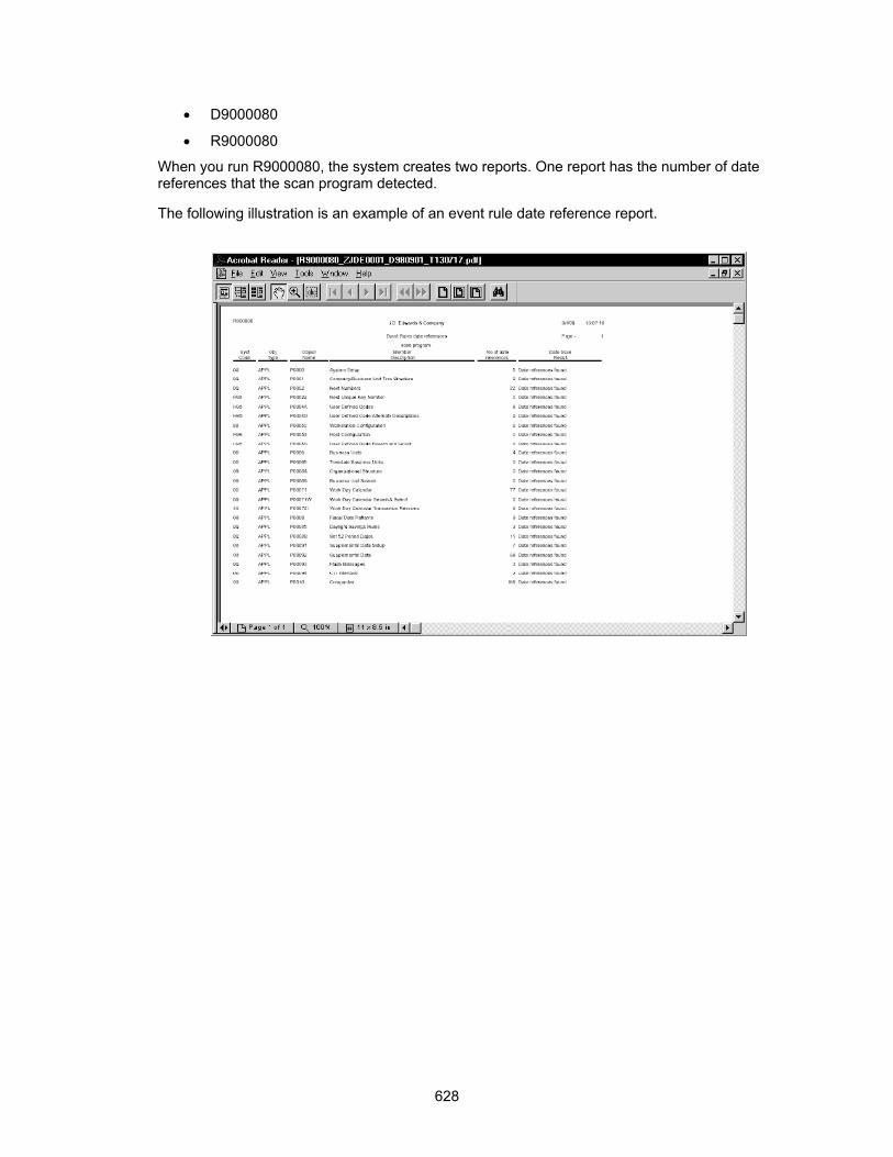
• D9000080
• R9000080
When you run R9000080, the system creates two reports. One report has the number of date references that the scan program detected.
The following illustration is an example of an event rule date reference report.
628

The other report shows the date reference details.
The following illustration is an example of an event rule date reference detail report.
629

630