Embed Size (px)
Citation preview

1 of 107
Indian Point Energy Center Large Power Transformer Life Cycle
Management Plan
Prepared: Christopher A. Ingrassia Reviewed: Vincent Andreozzi
Approved: Richard Burroni
Date: 5/9/11 (edited 7/7/11)
ENT000125 Submitted: March 28, 2012

2 of 107
Table Of Contents
Purpose .............................................................................................................................. 4 References .......................................................................................................................... 4 Unit 2 Unit Auxiliary Transformer (UAT) ..................................................................... 5
Winding Insulation .......................................................................................................... 5 Internal Bus Supports .................................................................................................... 10 Core ............................................................................................................................... 11 Tank .............................................................................................................................. 11 Bushings ........................................................................................................................ 12 Oil Pumps, Control Cabinet Devices, Tap Changer, Current Transformers and Protective Relays .......................................................................................................... 12
Unit 3 Unit Auxiliary Transformer (UAT) ................................................................... 17 Winding Insulation ........................................................................................................ 17 Internal Bus Supports .................................................................................................... 20 Core ............................................................................................................................... 21 Tank .............................................................................................................................. 21 Bushings ........................................................................................................................ 22 Oil Pumps, Control Cabinet Devices, Tap Changer, Current Transformers and Protective Relays .......................................................................................................... 23
Unit 2 Station Auxiliary Transformer (SAT) ............................................................... 29 Winding Insulation ........................................................................................................ 29 Internal Bus Supports .................................................................................................... 32 Core ............................................................................................................................... 33 Tank .............................................................................................................................. 33 Bushings ........................................................................................................................ 34 Oil Pumps, Control Cabinet Devices, Tap Changer, Current Transformers and Protective Relays .......................................................................................................... 35
Unit 3 Station Auxiliary Transformer (SAT) ............................................................... 41 Winding Insulation ........................................................................................................ 41 Internal Bus Supports .................................................................................................... 44 Core ............................................................................................................................... 45 Tank .............................................................................................................................. 45 Bushings ........................................................................................................................ 46 Oil Pumps, Control Cabinet Devices, Tap Changer, Current Transformers and Protective Relays .......................................................................................................... 47
21 Main Transformer (21MT) ....................................................................................... 53 Winding Insulation ........................................................................................................ 53 Internal Bus Supports .................................................................................................... 56 Core ............................................................................................................................... 56 Tank .............................................................................................................................. 57 Bushings ........................................................................................................................ 57 Oil Pumps, Control Cabinet Devices, Tap Changer, Current Transformers and Protective Relays .......................................................................................................... 59

3 of 107
22 Main Transformer (22MT) ....................................................................................... 64 Winding Insulation ........................................................................................................ 64 Internal Bus Supports .................................................................................................... 67 Core ............................................................................................................................... 68 Tank .............................................................................................................................. 68 Bushings ........................................................................................................................ 69 Oil Pumps, Control Cabinet Devices, Tap Changer, Current Transformers and Protective Relays .......................................................................................................... 70
31 Main Transformer (31MT) ....................................................................................... 75 Winding Insulation ........................................................................................................ 75 Internal Bus Supports .................................................................................................... 79 Core ............................................................................................................................... 80 Tank .............................................................................................................................. 80 Bushings ........................................................................................................................ 81 Oil Pumps, Control Cabinet Devices, Tap Changer, Current Transformers and Protective Relays .......................................................................................................... 84
32 Main Transformer (32MT) ....................................................................................... 89 Winding Insulation ........................................................................................................ 89 Internal Bus Supports .................................................................................................... 93 Core ............................................................................................................................... 93 Tank .............................................................................................................................. 94 Bushings ........................................................................................................................ 94 Oil Pumps, Control Cabinet Devices, Tap Changer, Current Transformers and Protective Relays .......................................................................................................... 95
Unit 3 GT Auto Transformer (GT Auto) .................................................................... 100 Winding Insulation ...................................................................................................... 100 Internal Bus Supports .................................................................................................. 102 Core ............................................................................................................................. 103 Tank ............................................................................................................................ 103 Bushings ...................................................................................................................... 104 Oil Pumps, Control Cabinet Devices, Tap Changer, Current Transformers and Protective Relays ........................................................................................................ 104

4 of 107
Purpose The purpose of this plan is to determine the estimated service life for the IPEC large power transformers and their subcomponents. The estimated service life will be used to asses the current preventive maintenance (PM) and replacement strategies for the transformers. Also included in this plan are the stations large power transformer single point vulnerability (SPV) reviews and mitigation strategies. References
1. EPRI: Large Transformer End-of-Expected-Life Considerations and the Need for Planning
2. EPRI: Life Cycle Management Planning Sourcebooks, Volume 4 Large Power Transformers
3. SOER 10-2 (Large Power Transformer Reliability) Recommendation 2: Life Cycle Management
4. IEEE Std C57.104-2008 (IEEE Guide for the Interpretation of Gases Generated in Oil-Immersed Transformers)
5. EN-EE-G-001 (Entergy Nuclear Large Power Transformer Inspection Guidelines)

5 of 107
Unit 2 Unit Auxiliary Transformer (UAT) The Unit 2 UAT is a Westinghouse Type SL, FOA, 43MVA, 22/6.9kV with Type URT Tap Changer and has been in-service for 37 years (original plant equipment). The transformer provides power to the “in-side” buses while the plant is on-line. While on-line the transformer is loaded to ~30MW. The transformer is de-energized when the plant is off-line. The transformer is not operated under conditions that would result in accelerate age degradation (i.e. high temperatures, overload). While the transformer has seen transients within its lifetime (i.e. failure of 21 Main Transformer), there does not appear to be a correlating reduction in expected service life from them. Transformer replacement is in the stations Asset Management Plan (AMP) for 2014 (SIPD 921). This date is adequate for the estimated expected service life of the transformer and subcomponents.
Winding Insulation The minimum expected service life of the winding insulation is 2014. This is based upon current power factor and capacitance test data, dissolved gas analysis (DGA) and furanic compound analysis.
Unit 2 UAT Power Factor
00.10.20.30.40.50.60.70.8
11/15/02 4/9/08 3/16/10 11/13/10
Year
%Pf
CH CHL (UST)CHL CL
The power factor trend does not indicate any accelerated or adverse anomalies in the transformers insulating system. While the power factor has trended up, the trend is stable. Higher values on 4/9/08 and 3/16/10 may be attributable to different equipment/personnel performing the test. The higher values in CL, on those dates, can be attributed to testing the transformer farther down the bus and not directly at the low voltage terminals.

6 of 107
The power factor test is performed every four years. Based upon the trends in power factor the four year frequency is acceptable.
Unit 2 UAT Capacitance
0
5000
10000
15000
20000
25000
11/15/02 4/9/08 3/16/10 11/13/10
Year
Capa
cita
nce CH
CHL (UST)CHL CL
The capacitance trend does not indicate any adverse changes in the geometry of the windings. The capacitance test is performed every four years. Based upon the trends in capacitance the four year frequency is acceptable.

7 of 107
IPEC U2 UAT DGA
0102030405060708090
100
2/24
/09
5/24
/09
8/24
/09
11/2
4/09
2/24
/10
5/24
/10
8/24
/10
11/2
4/10
Date
PPM
Hydrogen (H2)
Methane (CH4)Ethane (C2H6)
Ethylene (C2H4)
Acetylene (C2H2)
IPEC U2 UAT CO/CO2
0
500
1000
1500
2000
2500
3000
3500
4000
12/1
/08
3/1/
09
6/1/
09
9/1/
09
12/1
/09
3/1/
10
6/1/
10
9/1/
10
12/1
/10
Date
PPM Carbon Monox. (CO)
Carbon Dioxide (CO2)
Ethylene is trending stable but above historic levels (50 to 60PPM). The trend has been evaluated using industry guidance, including consultation with Doble Engineering (CR-IP2-2011-03133). The evaluation has determined that the gassing in the transformer is due to high temperature (>700 oC) overheating of the oil. The overheating of the oil is most likely due to an overheated connection within the load tap changer (LTC) or an overheated core ground. With the LTC being less likely due to it being in a compartment separate from where the oil samples are being taken from (the main tank).

8 of 107
The evaluation of the gases in the transformer was performed using the following:
Key Gas Method The key gas method is detailed in IEEE Std C57.104TM-2008 (IEEE Guide for the Interpretation of Gases Generated din Oil-Immersed Transformers). The key gas method is a qualitative determination of the fault type based upon the relative proportion of the “key gases”. The fault types are: overheated oil, overheated cellulose, partial discharge (PD) in oil and arcing in oil. The key gases are: CO (Carbon Dioxide), H2 (Hydrogen), CH4 (Methane), C2H6 (Ethane), C2H4 (Ethylene) and C2H2 (Acetylene) The key gas method indicates that the gasses in the transformer are being generated due to overheated oil. Rodgers Ratio The Rodgers Ratio is detailed in IEEE Std C57.104TM-2008. The Rodgers Ratio determines the fault type based upon the ratio of key combustible gases. The fault types are: low-energy density arcing – PD, Arcing – high-energy discharge, low temperature thermal, thermal <700 oC and thermal >700 oC The ratios used are: (R1) CH4/H2, (R2) C2H2/C2H4 and (R5) C2H4/C2H6 The current ratios of gases in the transformer are: R1 = 1.06, R2 = 0 and R5 = 6.79 The Rodgers Ratio method indicates that the gasses in the transformer are being generated due to a thermal condition >700 oC

9 of 107
Corrective Actions IEEE Std C57.104TM-2008 contains guidance on sampling intervals and operating procedures for transformers that are gassing. The standard suggests the following:
Actions based on TCG (total combustible gas) The current estimated TCG is 0.08% with a rate of < 0.01 % per day. Based on this the standard recommends a sampling interval of annual and continued normal operation. Actions based on TDCG (total dissolved combustible gas) The current TDCG is 174 PPM with a rate of < 10 PPM per day. Based on this the standard recommends a sampling interval of annual and continued normal operation.
The NEIL Loss Control Standards were also reviewed and NEIL requires monthly sampling of the transformer until a minimum of three samples have been taken to determine the rate. Once the rate has been determined NEIL suggests returning to a normal sampling frequency (every six months) and operating the transformer normally, unless TGC or TDCG increased by > 10% since the previous sample. The transformer is being sampled on a monthly frequency which is within the recommendations of IEEE and NEIL. The transformer has been on a monthly sampling frequency since at least 2006. Doble Engineering was contacted and commented that while C2H4 has been increasing the rate is very low. They recommended the performance of thermography on the transformer to check for any overheated connections, noting that only connections close to the external surfaces of the tank could be seen. Thermography was performed under WO 282594 and no overheated connections were observed. Doble Engineering does not recommend going internal to the transformer at this time, based upon the very low rate of gassing and potentially not being able to find the cause of the condition. System Engineering is monitoring the trend in the transformer gases as a part of normal System Engineering monitoring and trending. At this point in time is not believed that the gassing condition will result in a winding insulation service life of less than 2014.

10 of 107
Furanic Compound Test Results
Sample Date
Top Oil Temp °C HMF FOL FAL AF MF
Overall FAL Rate
Estimated DP
Estimated Remaining Life to DP
200 Current
FAL Rate ug/L ug/L ug/L ug/L ug/L ug/L/Year % ug/L/Year 01/26/2011 60 < 1 < 1 9 < 1 < 1 0.21 1013 100 -227.96 11/08/2010 8 37 < 1 58 < 1 < 1 1.38 782 91 234.29 09/01/2010 68 < 1 < 1 14 < 1 2 0.33 958 99 -8.16 09/08/2009 60 < 1 < 1 22 < 1 12 0.54 902 97 5.04 09/11/2008 64 < 1 < 1 17 < 1 < 1 0.43 934 98 -25.67 02/25/2008 65 3 < 1 31 2 3 0.78 860 95 -6.89 09/19/2007 60 < 1 < 1 34 2 24 0.87 848 95
The furanic compound levels and rates do not indicate that accelerated decomposition of insulation is occurring. Following the 21 Main Transformer failure on 11/7/10 the levels (HMF and FAL) did increase when the transformer was sampled de-energized. A confirmatory sample was taken on 1/26/11 and the levels returned to their approximate historic values. The estimated DP does not indicate that the transformer insulation is at the end of its useful life (DP 200). It is acknowledged that the current estimated DP may be higher than actual due to oil processing over the life of the transformer. While the estimated DP over the life of the transformer is not known, it is not believed that it would contribute to the current estimated DP being anywhere close to end of useful life. The furan test is performed once a year. Based upon the trend in furans the yearly frequency is acceptable.
Internal Bus Supports The minimum expected service life of the internal bus supports is 2014, based on the following: EPRI identifies the failure mechanism of internal bus supports as: failure due to being under-designed. A search of Doble and INPO did not reveal any operating experience or Westinghouse service advisories that identify the bus supports in the transformer as being undersized. Failures of bus supports are also indicated by arcing/tracking. The dissolved gas analysis does not indicate that arcing is occurring within the transformer. Arcing would be indicated by the presence of Acetylene (C2H2). There are no useful PM tasks for internal bus supports.

11 of 107
Core The minimum expected service life of the core is 2014, based on the following: Problems with transformer cores include: loss of ground, multiple grounds or looseness. Multiple grounds would be indicated by overheating through DGA. As noted in the winding insulation section there is indication of overheating within the transformer. This overheating could potentially be related to the core of the transformer, but confirmation is difficult due to the very low rate of gassing and the inaccessibility of the core ground. Loss of core ground would be indicated by arcing or a significant decrease in CL capacitance, neither of these conditions exists. Looseness would be indicated by a change in 60Hz noise. While this is qualitative, there have been no reported changes in transformer noise by Operations or System Engineering. The transformer is being sampled for DGA on a monthly frequency. Based upon the trends in gases the monthly frequency is acceptable and within industry guidance. The capacitance test is performed every four years. Based upon the trends in capacitance the four year frequency is acceptable. The transformer is walked down at least daily by Operations and periodically by System Engineering. These task frequencies are acceptable based upon the current condition of the transformer. Note: The transformer core ground is not accessible from outside of the tank. Tank The minimum expected service life of the tank is 2014. This is based upon PM inspections of the tank along with Operations and System Engineering walkdowns. During these activities degradation to the tank would be documented via condition report (CR) and a work order (WO) would be written to correct the condition, if not corrected during the PM. The tank currently does not have any noted deficiencies that would reduce its expected service life. The transformer PM inspection is performed every two years and the transformer is walked down at least daily by Operations and periodically by System Engineering. These task frequencies are acceptable based upon the current condition of the transformer.

12 of 107
Bushings The minimum expected service life of the bushings is 2014, based on the following: The high voltage bushings are Westinghouse Type OS and the low voltage bushings are Westinghouse Type RJ. The bushings are original plant equipment.
Hot Collar Test Results mA 11/15/2002 4/9/2008 3/16/2010 11/13/2011 H1 0.133 0.152 0.111 H2 0.133 0.151 0.117 H3 0.133 0.147 0.102 X0 0.135 0.162 0.132 0.123 X1 0.137 0.153 0.149 0.134 X2 0.143 0.155 0.146 0.131 X3 0.142 0.153 0.144 0.133 Watts 11/15/2002 4/9/2008 3/16/2010 11/13/2010 H1 0.065 0.018 0.016 H2 0.068 0.019 0.016 H3 0.073 0.024 0.019 X0 0.041 0.063 0.022 0.021 X1 0.042 0.063 0.018 0.027 X2 0.042 0.059 0.028 0.026 X3 0.036 0.035 0.026 0.018
The hot collar test results do not indicate that any of the bushings are degraded or are starting to show signs of degradation. The test results for each bushing type are comparable to each other, within the same test date. The bushings are tested on a four year frequency. Based upon the trend in test results the four year frequency is acceptable. Oil Pumps, Control Cabinet Devices, Tap Changer, Current Transformers and Protective Relays These types of subcomponents have been identified as single point vulnerabilities (SPV). The maintenance and mitigation strategies are addressed in the attached SPV review. This will ensure that these components do not exceed their expected service lives.

13 of 107
ANO GGNS IPEC JAF PLP PNPS RBS VY W3 SYSTEM: 6.9K
COMPONENT: UAUX (Unit 2 Unit Auxiliary Transformer)
DATE: 3/1/11
UNIT TRIP OR DERATE INITIATING COMPONENT (Specify if Unit Trip or Derate): Unit Trip and Transformer Derate SINGLE POINT FAILURE VULNERABILITIES: Trip:
1. Internal Components (windings, insulation, core, oil, tap changer) 2. Bushings 3. Current Transformers (CTs) 4. Protective Relays (87/UT, 51/UT, 51N/UT)
Derate/Removal from Service:
1. Oil Pumps (88P-1, 88P-2) 2. Circuit Breakers (8-2, 8-3, 8-6, 8-7, 8-8, 8-9, Pump Breakers, Fan Breakers) 3. Contactors (2-1, 2-2, 4-1, 4-2, 27-1, 27-2) 4. Control Power Transformer (AT) 5. Loss of Oil
Reference Drawings: A208377, 5334D31, 9321-LL-3132 Sheet 2 PLANT OPERATING EXPERIENCE: • CR-IP2-2010-06801 (21 Main Transformer
Failure) • CR-IP3-2007-01834 (31 Main Transformer
Failure) • CR-IP2-2009-00959 (Loss of UAT Cooling due
to Coordination Issue)
INDUSTRY OPERATING EXPERIENCE: • SOER 10-1 (Large Power Transformer
Reliability) • IER L3-10-6 (Loss of Transformer Cooling due
to CPT Failure) • OE31908 (Partial Loss of Transformer Cooling
due to Damaged Plug Connector) • OE29135 and OE32417 (Loss of Transformer
Cooling due to CPT Failure caused by Contactor Failure)
• OE20943 (Loss of Transformer Cooling due to Coordination Issue)
• OE29330 (Loss of Transformer Cooling due Age Degraded MCCB Failing to Trip)
• OE14335 (Transformer Trip due to Gap Type LA Failure) also see INPO TR4-40.
• SEN 275 (HV Bushing Failure due to Failure at Test Tap)

14 of 107
MITIGATION STRATEGY(List proposed corrective actions, recommended implementation timeline, actions taken, actions pending, and document tracking number (i.e. PCRS, Work Order, Engineering Change Request, Modification). Attachment 9.5 provides sample SPF Mitigation Strategies.): Trip:
1. Internal Components (windings, insulation, core, oil, tap changer)
• Continue with existing predictive electrical testing (power factor, capacitance, winding resistance, TTR, SFRA, etc.).
PMRQ: 50057994-02 Procedure: 0-XFR-403-ELC
• Continue with existing periodic oil samples (DGA, Oil Quality and Furans). Procedure: 0-CY-2655
• Continue with existing thermography scans. PMRQ: 22451-01 MWO: 198051
• Continue with existing preventive maintenance on the tap changer. PMRQ: 50057994-05 Procedure: 0-XFR-409-ELC
2. Bushings
• Continue with existing predictive electrical testing (power factor) and maintenance.
PMRQ: 50057994-02 Procedure: 0-XFR-403-ELC
• Continue with existing thermography scans. PMRQ: 22451-01 MWO: 198051
3. Current Transformers (CTs)
• Continue with existing preventive maintenance.
PMRQ: 50057994-03 Procedure: 2-IC-PC-I-E-UAUX CT
4. Protective Relays (87/UT, 51/UT, 51N/UT)
• Continue with existing periodic calibration of the relays.
PMRQs: 50061732, 50062144, 50062145 and 19979 MWOs: 51507486, 51507487, 51507488 and 51507489

15 of 107
Derate/Removal from Service:
1. Oil Pumps (88P-1, 88P-2)
• Continue with existing periodic oil pump replacement. PMRQs: 50057994-06 MWOs: 51504130
2. Circuit Breakers (8-2, 8-3, 8-6, 8-7, 8-8, 8-9, Pump Breakers, Fan Breakers)
• As documented in CR-IP2-2009-00959 the transformer auxiliaries are not
selectively coordinated and the condition can lead to a loss of all transformer cooling and tap changer controls. It is recommended to resolve the coordination issue in the next outage (2R20). The modification will replace circuit breakers 8-7 and 8-8 with fuses and the pump and fan breakers will be replaced by motor starter protectors. (SIPD 904)
• Perform a one time replacement of the circuit breakers not being replaced through the coordination mod. WO 265674 has been initiated to replace breakers 8-2, 8-3, 8-6 and 8-9. It is recommended to replace these breakers in the next outage 2R20.
• Continue with existing PM to cycle the breakers on a periodic basis. PMRQ: 50057994-02 Procedure: 0-XFR-403-ELC
• Continue with existing thermography scans. PMRQ: 22451-01 MWO: 198051
3. Contactors (2-1, 2-2, 4-1, 4-2, 27-1, 27-2)
• Perform a one time replacement of the contactors. WO 265676 has been initiated to
replace contactors. It is recommended to replace these contactors in the next outage 2R20.
• Continue with existing thermography scans. PMRQ: 22451-01 MWO: 198051
4. Control Power Transformer (AT)
• Perform a one time replacement of the CPT. WO 265678 has been initiated to
replace the CPT. It is recommended to replace the CPT in the next outage 2R20. • Continue with existing thermography scans.
PMRQ: 22451-01 MWO: 198051

16 of 107
5. Loss of Oil
• Continue with existing preventive maintenance. PMRQ: 50057994-02 Procedure: 0-XFR-403-ELC
• Continue with existing Operator rounds and System Engineering walkdowns. Overall a review was performed of the procedures and MWOs referenced for the SPVs. The review identified changes that can be made to the procedures that will enhance the maintenance of the SPVs. The procedure changes are associated with 0-XFR-403-ELC (Transformer PM), 2-IC-PC-I-E-UAUX CT and MWO 198051 (Thermography). CAs-27, 28 and 29 under CR-IP2-2010-01985 have been assigned to implement the changes. BASIS FOR CONCLUSIONS: The combination of preventive maintenance, predictive maintenance, one time equipment change outs, modification of the protective devices for the transformer auxiliaries and procedure enhancements will mitigate the identified single point vulnerabilities. The current preventive maintenance performed on the transformer can adequately mitigate the identified vulnerabilities. The preventive maintenance in place is based upon, but not limited to, the following:
• EN-Transformer-Oil Immersed PM Basis Template • Vendor Manuals • Documentation contained in PM change requests (PMCRs).
The current predictive maintenance (i.e. electrical testing, oil sampling, thermography) performed on the transformer can provide advance warning to mitigate degradation prior to equipment failure. The information gathered from predictive maintenance is used in System Engineering Monitoring and Trending and also feeds into the sites Transformer Long Range Plan. The predictive maintenance in place is based upon, but not limited to, the following fleet and industry guidance:
• EN-Transformer-Oil Immersed PM Basis Template • EN-EE-G-001 (Large Power Transformer Inspection Guidelines) • IEEE Std C57.104 (IEEE Guide for the Interpretation of Gases Generated in Oil-Immersed
Transformers) • IEEE Std C57.106 (IEEE Guide for Acceptance and Maintenance of Insulating Oil in
Equipment) • Doble Test Procedures Manual
The one time replacement of components can adequately mitigate the identified vulnerabilities. These types of components (i.e. breakers, contactors, CPTs) have a life expectancy that typically exceeds 20 years of operation. This life expectancy will be adequate for the remaining operating life of the plant and/or transformer. The transformer auxiliaries are not selectively coordinated (CR-IP2-2009-00959). This issue can lead to a loss of all transformer cooling and a loss of tap changer controls, requiring a Unit Shutdown. Based upon this it is recommended to resolve the coordination issue at the next opportunity (2R20).

17 of 107
Unit 3 Unit Auxiliary Transformer (UAT) The Unit 3 UAT is a Westinghouse Type SL, FOA, 43MVA, 22/6.9kV with Type URT Tap Changer and has been in-service for 35 years (original plant equipment, rewound in the early 1980’s). The transformer provides power to the “in-side” buses while the plant is on-line. While on-line the transformer is loaded to ~30MW. The transformer is de-energized when the plant is off-line. The transformer is not operated under conditions that would result in accelerate age degradation (i.e. high temperatures, overload). While the transformer has seen transients within its lifetime (i.e. failure of 31 Main Transformer), there does not appear to be a correlating reduction in expected service life from them. Transformer replacement is in the stations Asset Management Plan (AMP) for 2015 (SIPD 730). This date is adequate for the estimated expected service life of the transformer and subcomponents.
Winding Insulation The minimum expected service life of the winding insulation is 2015. This is based upon current power factor and capacitance test data, dissolved gas analysis (DGA) and furanic compound analysis.
Unit 3 UAT Power Factor
0.00
0.10
0.20
0.30
0.40
0.50
0.60
2007 2009 2011
Date
%PF CH
CHL(UST)CHLCL
The power factor trend does not indicate any accelerated or adverse anomalies in the transformers insulating system. The power factor test is performed every four years. Based upon the trends in power factor the four year frequency is acceptable.

18 of 107
Unit 3 UAT Capacitance
0
5000
10000
15000
20000
25000
30000
2007 2009 2011
Date
pF
CHCHL(UST)CHLCL
The capacitance trend does not indicate any adverse changes in the geometry of the windings. The capacitance test is performed every four years. Based upon the trends in capacitance the four year frequency is acceptable.

19 of 107
IPEC U3 UAT DGA
0
10
20
30
40
50
60
2/25
/200
9
4/25
/200
9
6/25
/200
9
8/25
/200
9
10/2
5/20
09
12/2
5/20
09
2/25
/201
0
4/25
/201
0
6/25
/201
0
8/25
/201
0
10/2
5/20
10
12/2
5/20
10
2/25
/201
1
Date
PPM
Hydrogen (H2)
Methane (CH4)
Ethane (C2H6)
Ethylene (C2H4)
Acetylene (C2H2)
IPEC U3 UAT CO/CO2
0
1000
2000
3000
4000
5000
6000
7000
8000
2/25
/200
9
4/25
/200
9
6/25
/200
9
8/25
/200
9
10/2
5/20
09
12/2
5/20
09
2/25
/201
0
4/25
/201
0
6/25
/201
0
8/25
/201
0
10/2
5/20
10
12/2
5/20
10
2/25
/201
1
Date
PPM Carbon Monox. (CO)
Carbon Dioxide (CO2)
Hydrogen did trend above historic levels in the spring of 2010. The Hydrogen has since trended down. The condition is being monitored under normal System Engineering monitoring and trending. All other gases are well within industry standards and trending steady. At this point in time is not believed that the gassing condition will result in a winding insulation service life of less than 2015. The transformer is being sampled on a quarterly frequency. Based upon the trends in gases the quarterly frequency is acceptable and within industry guidance.
20 of 107
Furanic Compound Test Results
Sample Date
Top Oil Temp °C HMF FOL FAL AF MF
Estimated DP
Estimated Remaining Life to DP
200 Current
FAL Rate ug/L ug/L ug/L ug/L ug/L % ug/L/Year 01/26/2011 60 4 < 1 64 2 41 770 91 -17.64 09/03/2010 66 1 < 1 71 2 36 757 90 28.39 09/21/2009 59 < 1 16 44 3 12 816 94 -30.18 09/11/2008 60 3 < 1 75 3 11 750 90 -18.32 02/25/2008 56 3 < 1 85 3 19 734 89 27.56 09/19/2007 52 < 1 < 1 73 < 1 20 753 90
The furanic compound levels and rates do not indicate that accelerated decomposition of insulation is occurring. The estimated DP does not indicate that the transformer insulation is at the end of its useful life (DP 200). It is acknowledged that the current estimated DP may be higher than actual due to oil processing over the life of the transformer. While the estimated DP over the life of the transformer is not known, it is not believed that it would contribute to the current estimated DP being anywhere close to end of useful life. The furan test is performed once a year. Based upon the trend in furans the yearly frequency is acceptable.
Internal Bus Supports The minimum expected service life of the internal bus supports is 2015, based on the following: EPRI identifies the failure mechanism of internal bus supports as: failure due to being under-designed. A search of Doble and INPO did not reveal any operating experience or Westinghouse service advisories that identify the bus supports in the transformer as being undersized. Failures of bus supports are also indicated by arcing/tracking. The dissolved gas analysis does not indicate that arcing is occurring within the transformer. Arcing would be indicated by the presence of Acetylene (C2H2). There are no useful PM tasks for internal bus supports.

21 of 107
Core The minimum expected service life of the core is 2015, based on the following: Problems with transformer cores include: loss of ground, multiple grounds or looseness. Multiple grounds would be indicated by overheating through DGA. The DGA does not indicate that overheating is occurring. Loss of core ground would be indicated by arcing or a significant decrease in CL capacitance, neither of these conditions exists. Looseness would be indicated by a change in 60Hz noise. While this is qualitative, there have been no reported changes in transformer noise by Operations or System Engineering. The transformer is being sampled for DGA on a quarterly frequency. Based upon the trends in gases the quarterly frequency is acceptable and within industry guidance. The capacitance test is performed every four years. Based upon the trends in capacitance the four year frequency is acceptable. The transformer is walked down at least daily by Operations and periodically by System Engineering. These task frequencies are acceptable based upon the current condition of the transformer. Note: The transformer core ground is not accessible from outside of the tank. Tank The minimum expected service life of the tank is 2015. This is based upon PM inspections of the tank along with Operations and System Engineering walkdowns. During these activities degradation to the tank would be documented via condition report (CR) and a work order (WO) would be written to correct the condition, if not corrected during the PM. During the last PM of the transformer in 2011 an area of surface corrosion was noted where the neutral bushing enters the top of the transformer (CR-IP3-2011-01806, WO 52214433-02). The WO is scheduled for the next outage in 2013. The condition is not expected to compromise the tank boundary over the next two years. The transformer PM inspection is performed every two years and the transformer is walked down at least daily by Operations and periodically by System Engineering. These task frequencies are acceptable based upon the current condition of the transformer.

22 of 107
Bushings The minimum expected service life of the bushings is 2015, based on the following: The high voltage bushings are Westinghouse Type OS and the low voltage bushings are Westinghouse Type RJ. The bushings are original plant equipment.
Unit 3 UAT Bushing Power Factor
0
0.2
0.4
0.6
0.8
1
Nameplate 4/11/2007 3/26/2009 4/1/2011
Year Tested
%P
F
H1 PFH2 PFH3 PF
Unit 3 UAT Bushing Capacitance
320
330
340
350
360
370
380
390
Nameplate 4/11/2007 3/26/2009 4/1/2011
Date
pF
H1 CapH2 CapH3 Cap

23 of 107
Hot Collar Test Results mA 4/11/2007 3/26/2009 4/1/2011X0 0.1050 0.1150X1 0.0580 0.1200 0.1110X2 0.0500 0.1240 0.1110X3 0.0530 0.1250 0.0990 Watts 4/11/2007 3/26/2009 4/1/2011X0 0.0390 0.0530X1 0.0060 0.0590 0.0580X2 0.0050 0.0690 0.0570X3 0.0050 0.0580 0.0300
The power factor and capacitance test results do not indicate that any of the high voltage bushings are degraded or are starting to show signs of degradation. The hot collar test results do not indicate that any of the low voltage bushings are degraded or are starting to show signs of degradation. The test results for each bushing type are comparable to each other, within the same test date. The bushings are tested on a four year frequency. Based upon the trend in test results the four year frequency is acceptable. Oil Pumps, Control Cabinet Devices, Tap Changer, Current Transformers and Protective Relays These types of subcomponents have been identified as single point vulnerabilities (SPV). The maintenance and mitigation strategies are addressed in the attached SPV review. This will ensure that these components do not exceed their expected service lives.

24 of 107
ANO GGNS IPEC JAF PLP PNPS RBS VY W3 SYSTEM: 6.9K
COMPONENT: UAT (Unit 3 Unit Auxiliary Transformer)
DATE: 3/1/11
UNIT TRIP OR DERATE INITIATING COMPONENT (Specify if Unit Trip or Derate): Unit Trip and Transformer Derate SINGLE POINT FAILURE VULNERABILITIES: Trip:
1. Internal Components (windings, insulation, core, oil, tap changer) 2. Bushings 3. Current Transformers (CTs) 4. Protective Relays (87/UT, 51/UT, 51N/UT)
Derate/Removal from Service:
1. Oil Pumps (88P-1, 88P-2) 2. Circuit Breakers (8-2, 8-3, 8-6, 8-7, 8-8, 8-9, Pump Starter/Protector, Fan Starter/Protector) 3. Contactors (2-1, 2-2, 4-1, 4-2, 27-1, 27-2) 4. Control Power Transformer (AT) 5. Loss of Oil
Reference Drawings: A208377, 5334D31, 9321-LL-3132 Sheet 2 PLANT OPERATING EXPERIENCE: • CR-IP2-2010-06801 (21 Main Transformer
Failure) • CR-IP3-2007-01834 (31 Main Transformer
Failure) • CR-IP2-2009-00959 (Loss of UAT Cooling due
to Coordination Issue)
INDUSTRY OPERATING EXPERIENCE: • SOER 10-1 (Large Power Transformer
Reliability) • IER L3-10-6 (Loss of Transformer Cooling due
to CPT Failure) • OE31908 (Partial Loss of Transformer Cooling
due to Damaged Plug Connector) • OE29135 and OE32417 (Loss of Transformer
Cooling due to CPT Failure caused by Contactor Failure)
• OE20943 (Loss of Transformer Cooling due to Coordination Issue)
• OE29330 (Loss of Transformer Cooling due Age Degraded MCCB Failing to Trip)
• OE14335 (Transformer Trip due to Gap Type LA Failure) also see INPO TR4-40.
• SEN 275 (HV Bushing Failure due to Failure at Test Tap)

25 of 107
MITIGATION STRATEGY(List proposed corrective actions, recommended implementation timeline, actions taken, actions pending, and document tracking number (i.e. PCRS, Work Order, Engineering Change Request, Modification). Attachment 9.5 provides sample SPF Mitigation Strategies.): Trip:
1. Internal Components (windings, insulation, core, oil, tap changer)
• Continue with existing predictive electrical testing (power factor, capacitance, winding resistance, TTR, SFRA, etc.).
PMRQ: 50071040-04 Procedure: 0-XFR-403-ELC
• Continue with existing periodic oil samples (DGA, Oil Quality and Furans). Procedure: 0-CY-2655
• Continue with existing thermography scans. PMRQ: 21885-01 MWO: 193374
• Continue with existing preventive maintenance on the tap changer. PMRQ: 50071040-03 Procedure: 0-XFR-409-ELC
2. Bushings
• Continue with existing predictive electrical testing (power factor) and maintenance.
PMRQ: 50071040-04 Procedure: 0-XFR-403-ELC
• Continue with existing thermography scans. PMRQ: 21885-01 MWO: 193374
3. Current Transformers (CTs)
• Continue with existing preventive maintenance.
PMRQ: 50071040-05 Procedure: 3-IC-PC-I-E-UAUX CT
4. Protective Relays (87/UT, 51/50UT, 51N/UT)
• Continue with existing periodic calibration of the relays.
PMRQs: 50071411, 50071412, 50071410, 50071404, 50071403, 50071402 and 50071400
MWOs: 51491960, 51491961, 51491959, 51491947, 51491946, 51491945 and 51491943

26 of 107
Derate/Removal from Service:
1. Oil Pumps (88P-1, 88P-2)
• Continue with existing periodic oil pump replacement. PMRQs: 50071624-02 and 50071621-02 MWOs: 188333 and 188334
2. Circuit Breakers (8-2, 8-3, 8-6, 8-7, 8-8, 8-9, Pump Starter/Protector, Fan Starter/Protector)
• As documented in CR-IP2-2009-00959 the transformer auxiliaries are not
selectively coordinated and the condition can lead to a loss of all transformer cooling and tap changer controls. It is recommended to resolve the coordination issue in the next outage (3R17). The modification will replace circuit breakers 8-7 and 8-8 with fuses. The pump and fan breakers have already been replaced by motor starter protectors. (SIPD 907)
• Perform a one time replacement of the circuit breakers not being replaced through the coordination mod. WO 265679 has been initiated to replace breakers 8-2, 8-3, 8-6 and 8-9. It is recommended to replace these breakers in the next outage 3R17.
• Continue with existing PM to cycle the breakers on a periodic basis. PMRQ: 50071040-04 Procedure: 0-XFR-403-ELC
• Continue with existing thermography scans. PMRQ: 21885-01 MWO: 193374
3. Contactors (2-1, 2-2, 4-1, 4-2, 27-1, 27-2)
• Perform a one time replacement of the contactors. WO 265680 has been initiated to
replace the contactors. It is recommended to replace these contactors in the next outage 3R17.
• Continue with existing thermography scans. PMRQ: 21885-01 MWO: 193374
4. Control Power Transformer (AT)
• Perform a one time replacement of the CPT. WO 265682 has been initiated to
replace the CPT. It is recommended to replace the CPT in the next outage 3R17. • Continue with existing thermography scans.
PMRQ: 21885-01 MWO: 193374

27 of 107
5. Loss of Oil
• Continue with existing preventive maintenance. PMRQ: 50071040-04 Procedure: 0-XFR-403-ELC
• Continue with existing Operator rounds and System Engineering walkdowns. Overall a review was performed of the procedures and MWOs referenced for the SPVs. The review identified changes that can be made to the procedures that will enhance the maintenance of the SPVs. The procedure changes are associated with 0-XFR-403-ELC (Transformer PM), 3-IC-PC-I-E-UAUX CT and MWO 193374 (Thermography). CAs-27, 28 and 29 under CR-IP2-2010-01985 has been assigned to implement the changes. BASIS FOR CONCLUSIONS: The combination of preventive maintenance, predictive maintenance, one time equipment change outs, modification of the protective devices for the transformer auxiliaries and procedure enhancements will mitigate the identified single point vulnerabilities. The current preventive maintenance performed on the transformer can adequately mitigate the identified vulnerabilities. The preventive maintenance in place is based upon, but not limited to, the following:
• EN-Transformer-Oil Immersed PM Basis Template • Vendor Manuals • Documentation contained in PM change requests (PMCRs).
The current predictive maintenance (i.e. electrical testing, oil sampling, thermography) performed on the transformer can provide advance warning to mitigate degradation prior to equipment failure. The information gathered from predictive maintenance is used in System Engineering Monitoring and Trending and also feeds into the sites Transformer Long Range Plan. The predictive maintenance in place is based upon, but not limited to, the following fleet and industry guidance:
• EN-Transformer-Oil Immersed PM Basis Template • EN-EE-G-001 (Large Power Transformer Inspection Guidelines) • IEEE Std C57.104 (IEEE Guide for the Interpretation of Gases Generated in Oil-Immersed
Transformers) • IEEE Std C57.106 (IEEE Guide for Acceptance and Maintenance of Insulating Oil in
Equipment) • Doble Test Procedures Manual
The one time replacement of components can adequately mitigate the identified vulnerabilities. These types of components (i.e. breakers, contactors, CPTs) have a life expectancy that typically exceeds 20 years of operation. This life expectancy will be adequate for the remaining operating life of the plant and/or transformer. The transformer auxiliaries are not selectively coordinated (CR-IP2-2009-00959). This issue can lead to a loss of all transformer cooling and a loss of tap changer controls, requiring a Unit Shutdown. Based upon this it is recommended to resolve the coordination issue at the next opportunity (3R17).

28 of 107
The transformer has manual motor starter/protectors for the fans and pumps (Cutler-Hammer Type A302HN). A search of INPO operating experience did not find any past issues with these devices. A review of the vendor manual did not reveal any vendor recommended maintenance or replacement frequency. Based up this there are no reasons to suspect these devices will fail to perform their functions for the remaining operating life of the plant and/or transformer. The motor starter/protectors were installed in 2001 as part of the resolution for a coordination issue with the transformer auxiliaries.

29 of 107
Unit 2 Station Auxiliary Transformer (SAT) The Unit 2 SAT is a Westinghouse Type SL, FOA, 43MVA, 22/6.9kV with Type URT Tap Changer and has been in-service for 37 years (original plant equipment). The transformer provides the normal off-site power source to the plant. The transformer is normally energized and lightly loaded (~ 5MW) while the plant is on-line. Higher loading does occur when the plant is shutdown and above cold shutdown. The transformer is not operated under conditions that would result in accelerate age degradation (i.e. high temperatures, overload). While the transformer has seen transients within its lifetime (i.e. in plant motor failures), there does not appear to be a correlating reduction in expected service life from them. Transformer replacement is in the stations Asset Management Plan (AMP) for 2016 (SIPD 545). This date is adequate for the estimated expected service life of the transformer and subcomponents.
Winding Insulation The minimum expected service life of the winding insulation is 2016. This is based upon current power factor and capacitance test data, dissolved gas analysis (DGA) and furanic compound analysis.
Unit 2 SAT Power Factor
0
0.10.2
0.30.4
0.50.6
0.7
11/5/2002 4/5/2008 3/24/2010
Date Tested
%PF CH
CHL (UST)CHL CL
The power factor trend does not indicate any accelerated or adverse anomalies in the transformers insulating system. The power factor test is performed every four years. Based upon the trends in power factor the four year frequency is acceptable.
30 of 107
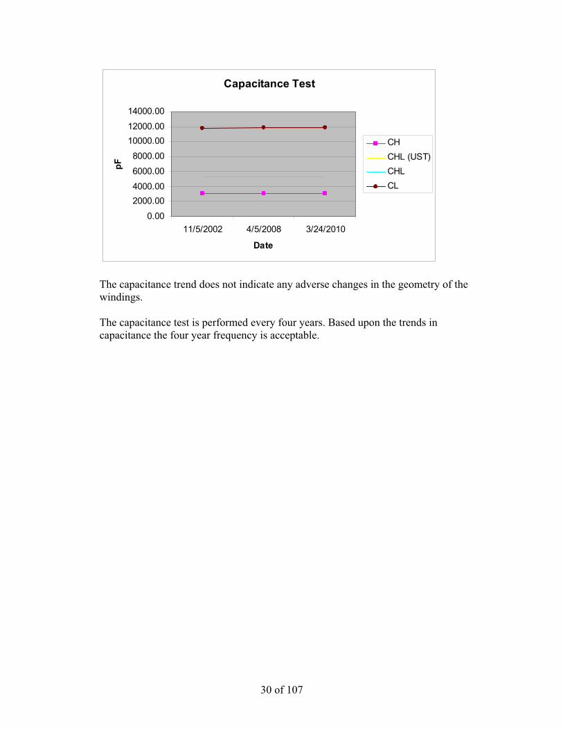
Capacitance Test
0.00
2000.004000.00
6000.00
8000.00
10000.0012000.00
14000.00
11/5/2002 4/5/2008 3/24/2010
Date
pF
CH CHL (UST)CHL CL
The capacitance trend does not indicate any adverse changes in the geometry of the windings. The capacitance test is performed every four years. Based upon the trends in capacitance the four year frequency is acceptable.
31 of 107
IPEC U2 SAT DGA
0
2
4
6
8
10
12
9/7/
2008
12/7
/200
8
3/7/
2009
6/7/
2009
9/7/
2009
12/7
/200
9
3/7/
2010
6/7/
2010
9/7/
2010
12/7
/201
0
Date
PPM
Hydrogen (H2)
Methane (CH4)
Ethane (C2H6)
Ethylene (C2H4)
Acetylene (C2H2)
IPEC U2 SAT CO/CO2
0.0
50.0
100.0
150.0
200.0
250.0
9/7/
2008
12/7
/200
8
3/7/
2009
6/7/
2009
9/7/
2009
12/7
/200
9
3/7/
2010
6/7/
2010
9/7/
2010
12/7
/201
0
Date
PPM Carbon Monox. (CO)
Carbon Dioxide (CO2)
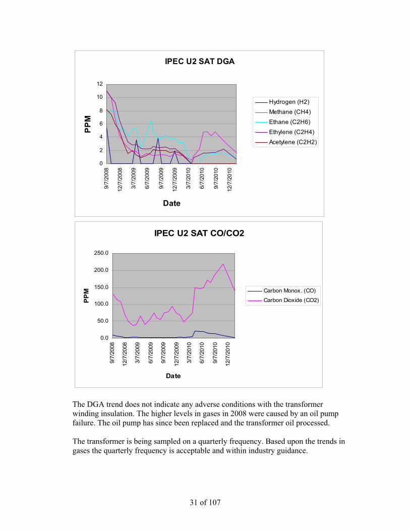
The DGA trend does not indicate any adverse conditions with the transformer winding insulation. The higher levels in gases in 2008 were caused by an oil pump failure. The oil pump has since been replaced and the transformer oil processed. The transformer is being sampled on a quarterly frequency. Based upon the trends in gases the quarterly frequency is acceptable and within industry guidance.

32 of 107
Furanic Compound Test Results
Sample Date
Top Oil Temp °C HMF FOL FAL AF MF
Overall FAL Rate
Estimated DP
Estimated Remaining Life to DP
200 Current
FAL Rate ug/L ug/L ug/L ug/L ug/L ug/L/Year % ug/L/Year 09/01/2010 38 < 1 < 1 2 < 1 < 1 0.05 1200 100 -3.06 09/08/2009 30 < 1 < 1 5 < 1 < 1 0.12 1086 100 0.00 09/07/2008 37 1 < 1 5 < 1 < 1 0.13 1086 100 5.61 02/25/2008 12 2 < 1 2 < 1 < 1 0.05 1200 100 -9.18 09/19/2007 27 < 1 < 1 6 < 1 2 0.15 1063 100
The furanic compound levels and rates do not indicate that accelerated decomposition of insulation is occurring. The estimated DP does not indicate that the transformer insulation is at the end of its useful life (DP 200). It is acknowledged that the current estimated DP may be higher than actual due to oil processing over the life of the transformer. While the estimated DP over the life of the transformer is not known, it is not believed that it would contribute to the current estimated DP being anywhere close to end of useful life. The furan test is performed once a year. Based upon the trend in furans the yearly frequency is acceptable.
Internal Bus Supports The minimum expected service life of the internal bus supports is 2016, based on the following: EPRI identifies the failure mechanism of internal bus supports as: failure due to being under-designed. A search of Doble and INPO did not reveal any operating experience or Westinghouse service advisories that identify the bus supports in the transformer as being undersized. Failures of bus supports are also indicated by arcing/tracking. The dissolved gas analysis does not indicate that arcing is occurring within the transformer. Arcing would be indicated by the presence of Acetylene (C2H2). There are no useful PM tasks for internal bus supports.

33 of 107
Core The minimum expected service life of the core is 2016, based on the following: Problems with transformer cores include: loss of ground, multiple grounds or looseness. Multiple grounds would be indicated by overheating through DGA. The DGA does not indicate that overheating is occurring. Loss of core ground would be indicated by arcing or a significant decrease in CL capacitance, neither of these conditions exists. Looseness would be indicated by a change in 60Hz noise. While this is qualitative, there have been no reported changes in transformer noise by Operations or System Engineering. The transformer is being sampled for DGA on a quarterly frequency. Based upon the trends in gases the quarterly frequency is acceptable and within industry guidance. The capacitance test is performed every four years. Based upon the trends in capacitance the four year frequency is acceptable. The transformer is walked down at least daily by Operations and periodically by System Engineering. These task frequencies are acceptable based upon the current condition of the transformer. Note: The transformer core ground is not accessible from outside of the tank. Tank The minimum expected service life of the tank is 2016. This is based upon PM inspections of the tank along with Operations and System Engineering walkdowns. During these activities degradation to the tank would be documented via condition report (CR) and a work order (WO) would be written to correct the condition, if not corrected during the PM. The tank currently does not have any noted deficiencies that would reduce its expected service life. The transformer PM inspection is performed every two years and the transformer is walked down at least daily by Operations and periodically by System Engineering. These task frequencies are acceptable based upon the current condition of the transformer.
34 of 107
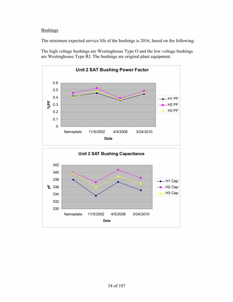
Bushings The minimum expected service life of the bushings is 2016, based on the following: The high voltage bushings are Westinghouse Type O and the low voltage bushings are Westinghouse Type RJ. The bushings are original plant equipment.
Unit 2 SAT Bushing Power Factor
0
0.1
0.2
0.3
0.4
0.5
0.6
Nameplate 11/5/2002 4/5/2008 3/24/2010
Date
%P
F
H1 PFH2 PFH3 PF
Unit 2 SAT Bushing Capacitance
330
332
334
336
338
340
342
Nameplate 11/5/2002 4/5/2008 3/24/2010
Date
pF
H1 CapH2 CapH3 Cap

35 of 107
Hot Collar Test Results mA 4/5/2008 3/24/2010X0 0.1610X1 0.1380 0.1580X2 0.1490 0.1580X3 0.1480 0.1590 Watts 4/5/2008 3/24/2010X0 0.0340X1 0.0470 0.0340X2 0.0480 0.0330X3 0.0500 0.0360
The power factor and capacitance test results do not indicate that any of the high voltage bushings are degraded or are starting to show signs of degradation.
The hot collar test results do not indicate that any of the bushings are degraded or are starting to show signs of degradation. The test results for each bushing type are comparable to each other, within the same test date. The bushings are tested on a four year frequency. Based upon the trend in test results the four year frequency is acceptable. Oil Pumps, Control Cabinet Devices, Tap Changer, Current Transformers and Protective Relays These types of subcomponents have been identified as single point vulnerabilities (SPV). The maintenance and mitigation strategies are addressed in the attached SPV review. This will ensure that these components do not exceed their expected service lives.

36 of 107
ANO GGNS IPEC JAF PLP PNPS RBS VY W3 SYSTEM: 6.9K
COMPONENT: STAUX (Unit 2 Station Auxiliary Transformer)
DATE: 3/1/11
UNIT TRIP OR DERATE INITIATING COMPONENT (Specify if Unit Trip or Derate): Transformer Trip and Transformer Derate Note: by the definition of EN-DC-175 the STAUX is not a SPV. With the plant in a normal line-up a loss of the STAUX will not trip the Unit or cause a derate. A loss of the transformer will however place the plant in a 72 hour shutdown LCO. This SPF Review is being conducted to meet the recommendations of SOER 10-1 (Large Transformer Reliability). SINGLE POINT FAILURE VULNERABILITIES: Trip:
1. Internal Components (windings, insulation, core, oil, tap changer) 2. Bushings 3. Current Transformers (CTs) 4. Lightning Arrestors (LAs) 5. Protective Relays (87/ST, 51/50ST, 51N/ST)
Derate/Removal from Service:
1. Oil Pumps (88P-1, 88P-2) 2. Circuit Breakers (8-2, 8-3, 8-6, 8-7, 8-8, 8-9, Pump Breakers, Fan Breakers) 3. Contactors (2-1, 2-2, 4-1, 4-2, 27-1, 27-2) 4. Control Power Transformer (AT) 5. Loss of Oil
Reference Drawings: A208377, 5341D31, 9321-LL-3132 Sheets 12 and 13 PLANT OPERATING EXPERIENCE: • CR-IP2-2010-06801 (21 Main Transformer
Failure) • CR-IP3-2007-01834 (31 Main Transformer
Failure) • CR-IP2-2009-00959 (Loss of UAT Cooling due
to Coordination Issue)
INDUSTRY OPERATING EXPERIENCE: • SOER 10-1 (Large Power Transformer
Reliability) • IER L3-10-6 (Loss of Transformer Cooling due
to CPT Failure) • OE31908 (Partial Loss of Transformer Cooling
due to Damaged Plug Connector) • OE29135 and OE32417 (Loss of Transformer
Cooling due to CPT Failure caused by Contactor Failure)
• OE20943 (Loss of Transformer Cooling due to Coordination Issue)
• OE29330 (Loss of Transformer Cooling due Age Degraded MCCB Failing to Trip)
• OE14335 (Transformer Trip due to Gap Type LA Failure) also see INPO TR4-40.
• SEN 275 (HV Bushing Failure due to Failure at Test Tap)
37 of 107
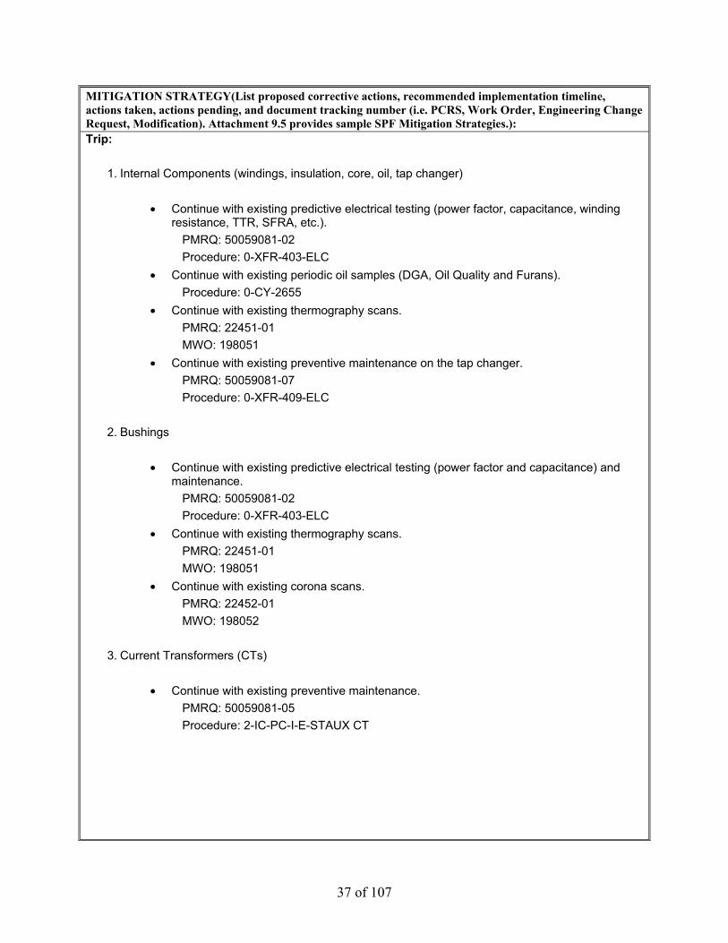
MITIGATION STRATEGY(List proposed corrective actions, recommended implementation timeline, actions taken, actions pending, and document tracking number (i.e. PCRS, Work Order, Engineering Change Request, Modification). Attachment 9.5 provides sample SPF Mitigation Strategies.): Trip:
1. Internal Components (windings, insulation, core, oil, tap changer)
• Continue with existing predictive electrical testing (power factor, capacitance, winding resistance, TTR, SFRA, etc.).
PMRQ: 50059081-02 Procedure: 0-XFR-403-ELC
• Continue with existing periodic oil samples (DGA, Oil Quality and Furans). Procedure: 0-CY-2655
• Continue with existing thermography scans. PMRQ: 22451-01 MWO: 198051
• Continue with existing preventive maintenance on the tap changer. PMRQ: 50059081-07 Procedure: 0-XFR-409-ELC
2. Bushings
• Continue with existing predictive electrical testing (power factor and capacitance) and
maintenance. PMRQ: 50059081-02 Procedure: 0-XFR-403-ELC
• Continue with existing thermography scans. PMRQ: 22451-01 MWO: 198051
• Continue with existing corona scans. PMRQ: 22452-01 MWO: 198052
3. Current Transformers (CTs)
• Continue with existing preventive maintenance.
PMRQ: 50059081-05 Procedure: 2-IC-PC-I-E-STAUX CT

38 of 107
4. Lightning Arrestors (LAs)
• The LAs on the STAUX are gap type and should be replaced. It is recommended to replace them in the next outage (2R20). LA replacement has been present to and approved by URT. Pending MPRC approval. (SIPD 1029)
• Continue with existing preventive maintenance. PMRQ: 50059081-04 Procedure: 0-ELC-400-LPS
5. Protective Relays (87/ST, 50/51ST, 51N/ST)
• Continue with existing periodic calibration of the relays.
PMRQs: 23696-01 and 23220-01 MWOs: 51506883 and 51506887
Derate/Removal from Service:
1. Oil Pumps (88P-1, 88P-2)
• Continue with existing periodic oil pump replacement. PMRQs: 50059081-08 MWOs: 51504129
2. Circuit Breakers (8-2, 8-3, 8-6, 8-7, 8-8, 8-9, Pump Breakers, Fan Breakers)
• As documented in CR-IP2-2009-00959 the transformer auxiliaries are not
selectively coordinated and the condition can lead to a loss of all transformer cooling and tap changer controls. It is recommended to resolve the coordination issue in the next outage (2R20). The modification will replace circuit breakers 8-7 and 8-8 with fuses and the pump and fan breakers will be replaced by motor starter protectors. (SIPD 904)
• Perform a one time replacement of the circuit breakers not being replaced through the coordination mod. WO 265483 has been initiated to replace breakers 8-2, 8-3, 8-6 and 8-9. It is recommended to replace these breakers in the next outage 2R20.
• Continue with existing PM to cycle the breakers on a periodic basis. PMRQ: 50059081-02 Procedure: 0-XFR-403-ELC
• Continue with existing thermography scans. PMRQ: 22451-01 MWO: 198051

39 of 107
3. Contactors (2-1, 2-2, 4-1, 4-2, 27-1, 27-2)
• Perform a one time replacement of the contactors. WO 265483 has been initiated to
replace the contactors. It is recommended to replace these contactors in the next outage 2R20.
• Continue with existing thermography scans. PMRQ: 22451-01 MWO: 198051
4. Control Power Transformer (AT)
• Perform a one time replacement of the CPT. WO 265485 has been initiated to
replace the CPT. It is recommended to replace the CPT in the next outage 2R20. • Continue with existing thermography scans.
PMRQ: 22451-01 MWO: 198051
5. Loss of Oil
• Continue with existing preventive maintenance. PMRQ: 50059081-02 Procedure: 0-XFR-403-ELC
• Continue with existing Operator rounds and System Engineering walkdowns. Overall a review was performed of the procedures and MWOs referenced for the SPVs. The review identified changes that can be made to the procedures that will enhance the maintenance of the SPVs. The procedure changes are associated with 0-XFR-403-ELC (Transformer PM) and MWO 198051 (Thermography). CAs-27 and 29 under CR-IP2-2010-01985 have been assigned to implement the changes. BASIS FOR CONCLUSIONS: The combination of preventive maintenance, predictive maintenance, one time equipment change outs, modification of the protective devices for the transformer auxiliaries and procedure enhancements will mitigate the identified single point vulnerabilities. The current preventive maintenance performed on the transformer can adequately mitigate the identified vulnerabilities. The preventive maintenance in place is based upon, but not limited to, the following:
• EN-Transformer-Oil Immersed PM Basis Template • Vendor Manuals • Documentation contained in PM change requests (PMCRs).
40 of 107
The current predictive maintenance (i.e. electrical testing, oil sampling, thermography, corona) performed on the transformer can provide advance warning to mitigate degradation prior to equipment failure. The information gathered from predictive maintenance is used in System Engineering Monitoring and Trending and also feeds into the sites Transformer Long Range Plan. The predictive maintenance in place is based upon, but not limited to, the following fleet and industry guidance:
• EN-Transformer-Oil Immersed PM Basis Template • EN-EE-G-001 (Large Power Transformer Inspection Guidelines) • IEEE Std C57.104 (IEEE Guide for the Interpretation of Gases Generated in Oil-Immersed
Transformers) • IEEE Std C57.106 (IEEE Guide for Acceptance and Maintenance of Insulating Oil in
Equipment) • Doble Test Procedures Manual
The one time replacement of components can adequately mitigate the identified vulnerabilities. These types of components (i.e. breakers, contactors, CPTs) have a life expectancy that typically exceeds 20 years of operation. This life expectancy will be adequate for the remaining operating life of the plant and/or transformer. The transformer auxiliaries are not selectively coordinated (CR-IP2-2009-00959). This issue can lead to a loss of all transformer cooling and a loss of tap changer controls, placing the plant in 72 hour shutdown LCO. Based upon this it is recommended to resolve the coordination issue at the next opportunity (2R20). The transformer has gap type lighting arrestors (LA) that are original plant equipment. Industry Operating Experience (INPO TR4-40) recommends replacing this type of LA with metal-oxide arrestors. Based upon this it is recommended to replace the LAs at the next opportunity (2R20).

41 of 107
Unit 3 Station Auxiliary Transformer (SAT) The Unit 3 SAT is a Westinghouse Type SL, FOA, 43MVA, 22/6.9kV with Type URT Tap Changer and has been in-service for 35 years (original plant equipment). The transformer provides the normal off-site power source to the plant. The transformer is normally energized and lightly loaded (~ 5MW) while the plant is on-line. Higher loading does occur when the plant is shutdown and above cold shutdown. The transformer is not operated under conditions that would result in accelerate age degradation (i.e. high temperatures, overload). While the transformer has seen transients within its lifetime (i.e. in plant motor failures), there does not appear to be a correlating reduction in expected service life from them. Transformer replacement is in the stations Asset Management Plan (AMP) for 2017 (SIPD 786). This date is adequate for the estimated expected service life of the transformer and subcomponents.
Winding Insulation The minimum expected service life of the winding insulation is 2017. This is based upon current power factor and capacitance test data, dissolved gas analysis (DGA) and furanic compound analysis.
Unit 3 SAT Power Factor
00.10.20.30.40.50.60.70.80.9
1
9/27/1999 3/21/2009 3/24/2011
%PF
CHCHL(UST)CHLCL
The power factor trend does not indicate any accelerated or adverse anomalies in the transformers insulating system. The power factor test is performed every four years. Based upon the trends in power factor the four year frequency is acceptable.

42 of 107
Unit 3 SAT Capacitance
0
2000
4000
6000
8000
10000
12000
14000
9/27/1999 3/21/2009 3/24/2011
pF
CHCHL(UST)CHLCL
The capacitance trend does not indicate any adverse changes in the geometry of the windings. The capacitance test is performed every four years. Based upon the trends in capacitance the four year frequency is acceptable.
43 of 107
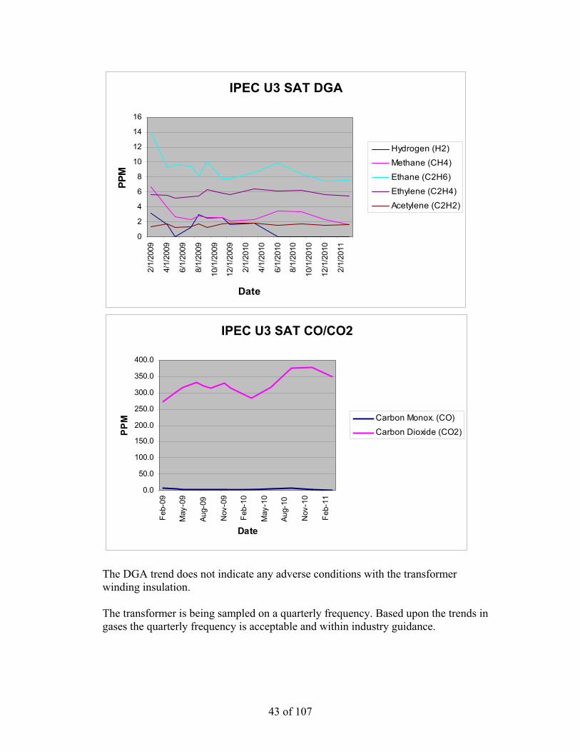
IPEC U3 SAT DGA
0
2
4
6
8
10
12
14
16
2/1/
2009
4/1/
2009
6/1/
2009
8/1/
2009
10/1
/200
9
12/1
/200
9
2/1/
2010
4/1/
2010
6/1/
2010
8/1/
2010
10/1
/201
0
12/1
/201
0
2/1/
2011
Date
PPM
Hydrogen (H2)
Methane (CH4)
Ethane (C2H6)
Ethylene (C2H4)
Acetylene (C2H2)
IPEC U3 SAT CO/CO2
0.0
50.0
100.0
150.0
200.0
250.0
300.0
350.0
400.0
Feb-
09
May
-09
Aug-
09
Nov
-09
Feb-
10
May
-10
Aug-
10
Nov
-10
Feb-
11
Date
PPM Carbon Monox. (CO)
Carbon Dioxide (CO2)
The DGA trend does not indicate any adverse conditions with the transformer winding insulation. The transformer is being sampled on a quarterly frequency. Based upon the trends in gases the quarterly frequency is acceptable and within industry guidance.

44 of 107
Furanic Compound Test Results
Sample Date
Top Oil Temp °C HMF FOL FAL AF MF
Estimated DP
Estimated Remaining Life to DP
200 Current
FAL Rate ug/L ug/L ug/L ug/L ug/L % ug/L/Year 03/10/2011 22 < 1 < 1 2 < 1 < 1 1200 100 -5.83 09/03/2010 40 < 1 < 1 5 < 1 < 1 1086 100 -1.05 09/21/2009 28 < 1 2 6 1 1 1063 100 2.92 09/11/2008 36 < 1 < 1 3 < 1 < 1 1149 100 3.66 02/25/2008 20 3 < 1 < 1 < 1 < 1 1286 100 -11.48 09/19/2007 52 < 1 < 1 6 < 1 < 1 1063 100
The furanic compound levels and rates do not indicate that accelerated decomposition of insulation is occurring. The estimated DP does not indicate that the transformer insulation is at the end of its useful life (DP 200). It is acknowledged that the current estimated DP may be higher than actual due to oil processing over the life of the transformer. While the estimated DP over the life of the transformer is not known, it is not believed that it would contribute to the current estimated DP being anywhere close to end of useful life. The furan test is performed once a year. Based upon the trend in furans the yearly frequency is acceptable.
Internal Bus Supports The minimum expected service life of the internal bus supports is 2017, based on the following: EPRI identifies the failure mechanism of internal bus supports as: failure due to being under-designed. A search of Doble and INPO did not reveal any operating experience or Westinghouse service advisories that identify the bus supports in the transformer as being undersized. Failures of bus supports are also indicated by arcing/tracking. The dissolved gas analysis does not indicate that arcing is occurring within the transformer. Arcing would be indicated by the presence of Acetylene (C2H2). There are no useful PM tasks for internal bus supports.

45 of 107
Core The minimum expected service life of the core is 2017, based on the following: Problems with transformer cores include: loss of ground, multiple grounds or looseness. Multiple grounds would be indicated by overheating through DGA. The DGA does not indicate that overheating is occurring. Loss of core ground would be indicated by arcing or a significant decrease in CL capacitance, neither of these conditions exists. Looseness would be indicated by a change in 60Hz noise. While this is qualitative, there have been no reported changes in transformer noise by Operations or System Engineering. The transformer is being sampled for DGA on a quarterly frequency. Based upon the trends in gases the quarterly frequency is acceptable and within industry guidance. The capacitance test is performed every four years. Based upon the trends in capacitance the four year frequency is acceptable. The transformer is walked down at least daily by Operations and periodically by System Engineering. These task frequencies are acceptable based upon the current condition of the transformer. Note: The transformer core ground is not accessible from outside of the tank. Tank The minimum expected service life of the tank is 2017. This is based upon PM inspections of the tank along with Operations and System Engineering walkdowns. During these activities degradation to the tank would be documented via condition report (CR) and a work order (WO) would be written to correct the condition, if not corrected during the PM. The tank currently does not have any noted deficiencies that would reduce its expected service life. The transformer PM inspection is performed every two years and the transformer is walked down at least daily by Operations and periodically by System Engineering. These task frequencies are acceptable based upon the current condition of the transformer.

46 of 107
Bushings The minimum expected service life of the bushings is 2017, based on the following: The high voltage bushings are Westinghouse Type O and the low voltage bushings are Westinghouse Type RJ. The bushings are original plant equipment.
Unit 3 SAT Bushing Power Factor
0
0.1
0.2
0.3
0.4
0.5
0.6
0.7
Nameplate 9/27/1999 3/21/2009 3/25/2011
Test Date
%PF
H1 PFH2 PFH3 PF
Unit 3 SAT Bushing Capacitance
342
344
346
348
350
352
354
Nameplate 9/27/1999 3/21/2009 3/24/2011
Test Date
pF
H1 CapH2 CapH3 Cap

47 of 107
Hot Collar Test Results
mA 3/21/2009 3/24/2011X0 0.1260 0.1120X1 0.1180 0.1110X2 0.1170 0.1110X3 0.1100 0.1030 Watts 3/21/2009 3/24/2011X0 0.0330 0.0330X1 0.0440 0.0190X2 0.0380 0.0210X3 0.0280 0.0240
The power factor and capacitance test results do not indicate that any of the high voltage bushings are degraded or are starting to show signs of degradation.
The hot collar test results do not indicate that any of the bushings are degraded or are starting to show signs of degradation. The test results for each bushing type are comparable to each other, within the same test date. The bushings are tested on a four year frequency. Based upon the trend in test results the four year frequency is acceptable. Oil Pumps, Control Cabinet Devices, Tap Changer, Current Transformers and Protective Relays These types of subcomponents have been identified as single point vulnerabilities (SPV). The maintenance and mitigation strategies are addressed in the attached SPV review. This will ensure that these components do not exceed their expected service lives.

48 of 107
ANO GGNS IPEC JAF PLP PNPS RBS VY W3 SYSTEM: 6.9K
COMPONENT: ST6 (Unit 3 Station Auxiliary Transformer)
DATE: 3/1/11
UNIT TRIP OR DERATE INITIATING COMPONENT (Specify if Unit Trip or Derate): Transformer Trip and Transformer Derate Note: by the definition of EN-DC-175 the SAT is not a SPV. With the plant in a normal line-up a loss of the SAT will not trip the Unit or cause a derate. A loss of the transformer will however place the plant in a 72 hour shutdown LCO. This SPF Review is being conducted to meet the recommendations of SOER 10-1 (Large Transformer Reliability). SINGLE POINT FAILURE VULNERABILITIES: Trip:
1. Internal Components (windings, insulation, core, oil, tap changer) 2. Bushings 3. Current Transformers (CTs) 4. Lightning Arrestors (LAs) 5. Protective Relays (87/ST, 51/50ST, 51N/ST)
Derate/Removal from Service: 1. Oil Pumps (88P-1, 88P-2) 2. Circuit Breakers/Fuses (8-2, 8-3, 8-6, 8-9, Pump Starter/Protector, Fan Starter/Protector, FU6641
thru FU6646) 3. Contactors (2-1, 2-2, 4-1, 4-2, 27-1, 27-2) 4. Control Power Transformer (AT) 5. Loss of Oil
Reference Drawings: 617F645, 5387D64, 9321-LL-31323 Sheets 12 and 13 PLANT OPERATING EXPERIENCE: • CR-IP2-2010-06801 (21 Main Transformer
Failure) • CR-IP3-2007-01834 (31 Main Transformer
Failure) • CR-IP2-2009-00959 (Loss of UAT Cooling due
to Coordination Issue)
INDUSTRY OPERATING EXPERIENCE: • SOER 10-1 (Large Power Transformer
Reliability) • IER L3-10-6 (Loss of Transformer Cooling due
to CPT Failure) • OE31908 (Partial Loss of Transformer Cooling
due to Damaged Plug Connector) • OE29135 and OE32417 (Loss of Transformer
Cooling due to CPT Failure caused by Contactor Failure)
• OE20943 (Loss of Transformer Cooling due to Coordination Issue)
• OE29330 (Loss of Transformer Cooling due Age Degraded MCCB Failing to Trip)
• OE14335 (Transformer Trip due to Gap Type LA Failure) also see INPO TR4-40.
• SEN 275 (HV Bushing Failure due to Failure at Test Tap)

49 of 107
MITIGATION STRATEGY(List proposed corrective actions, recommended implementation timeline, actions taken, actions pending, and document tracking number (i.e. PCRS, Work Order, Engineering Change Request, Modification). Attachment 9.5 provides sample SPF Mitigation Strategies.): Trip:
1. Internal Components (windings, insulation, core, oil, tap changer)
• Continue with existing predictive electrical testing (power factor, capacitance, winding resistance, TTR, SFRA, etc.).
PMRQ: 50070617-03 Procedure: 0-XFR-403-ELC
• Continue with existing periodic oil samples (DGA, Oil Quality and Furans). Procedure: 0-CY-2655
• Continue with existing thermography scans. PMRQ: 21885-01 MWO: 193374
• Continue with existing preventive maintenance on the tap changer. PMRQ: 50070617-09 Procedure: 0-XFR-409-ELC
2. Bushings
• Continue with existing predictive electrical testing (power factor and capacitance) and
maintenance. PMRQ: 50070617-03 Procedure: 0-XFR-403-ELC
• Continue with existing thermography scans. PMRQ: 21885-01 MWO: 193374
• Continue with existing corona scans. PMRQ: 21888-01 MWO: 193381
3. Current Transformers (CTs)
• Continue with existing preventive maintenance.
PMRQ: 50070617-04 Procedure: 3-IC-PC-I-E-STAUX CT

50 of 107
4. Lightning Arrestors (LAs)
• The LAs on the transformer are not included in the PM program. It is recommended to implement a PM of the LAs IAW procedure 0-ELC-400-LPS. The PM should be completed in 3R17.
PMCR 101121 has been completed to implement the PM. CA-21 of CR-IP2-2010-01985 documents the implementation the PMCR.
5. Protective Relays (87/ST, 50/51ST, 51N/ST)
• Continue with existing periodic calibration of the relays.
PMRQs: 50067619, 50067620, 50067621, 50067515, 50067516, 50067517 and 50067523
MWOs: 51487526, 51487528, 51487530, 51487394, 51487396, 51487398 and 51487412
Derate/Removal from Service:
1. Oil Pumps (88P-1, 88P-2)
• Continue with existing periodic oil pump replacement. PMRQs: 50070617-05 MWOs: 51493641
2. Circuit Breakers/Fuses (8-2, 8-3, 8-6, 8-9, Pump Starter/Protector, Fan Starter/Protector, FU6641
thru FU6646)
• Perform a one time replacement of circuit breakers 8-2, 8-3, 8-6 and 8-9. WO 265487 has been initiated to replace breakers. It is recommended to replace these breakers in 3R17.
• Continue with existing PM to cycle the breakers on a periodic basis. PMRQ: 50070617-03 Procedure: 0-XFR-403-ELC
• Continue with existing thermography scans. PMRQ: 21885-01 MWO: 193374

51 of 107
3. Contactors (2-1, 2-2, 4-1, 4-2, 27-1, 27-2)
• Perform a one time replacement of the contactors. WO 265488 has been initiated to replace contactors. It is recommended to replace these contactors in 3R17.
• Continue with existing thermography scans. PMRQ: 21885-01 MWO: 193374
4. Control Power Transformer (AT)
• Perform a one time replacement of the CPT. WO 265489 has been initiated to
replace the CPT. It is recommended to replace the CPT in 3R17. • Continue with existing thermography scans.
PMRQ: 21885-01 MWO: 193374
5. Loss of Oil
• Continue with existing preventive maintenance. PMRQ: 50070617-03 Procedure: 0-XFR-403-ELC
• Continue with existing Operator rounds and System Engineering walkdowns. Overall a review was performed of the procedures and MWOs referenced for the SPVs. The review identified changes that can be made to the procedures that will enhance the maintenance of the SPVs. The procedure changes are associated with 0-XFR-403-ELC (Transformer PM), 3-IC-PC-I-E-STAUX CT and MWO 193374 (Thermography). CAs-27, 28 and 29 under CR-IP2-2010-01985 has been assigned to implement the changes. BASIS FOR CONCLUSIONS: The combination of preventive maintenance, predictive maintenance, one time equipment change outs and procedure enhancements will mitigate the identified single point vulnerabilities. The current preventive maintenance performed on the transformer can adequately mitigate the identified vulnerabilities. The preventive maintenance in place is based upon, but not limited to, the following:
• EN-Transformer-Oil Immersed PM Basis Template • Vendor Manuals • Documentation contained in PM change requests (PMCRs).

52 of 107
The current predictive maintenance (i.e. electrical testing, oil sampling, thermography, corona) performed on the transformer can provide advance warning to mitigate degradation prior to equipment failure. The information gathered from predictive maintenance is used in System Engineering Monitoring and Trending and also feeds into the sites Transformer Long Range Plan. The predictive maintenance in place is based upon, but not limited to, the following fleet and industry guidance:
• EN-Transformer-Oil Immersed PM Basis Template • EN-EE-G-001 (Large Power Transformer Inspection Guidelines) • IEEE Std C57.104 (IEEE Guide for the Interpretation of Gases Generated in Oil-Immersed
Transformers) • IEEE Std C57.106 (IEEE Guide for Acceptance and Maintenance of Insulating Oil in
Equipment) • Doble Test Procedures Manual
The one time replacement of components can adequately mitigate the identified vulnerabilities. These types of components (i.e. breakers, contactors, CPTs) have a life expectancy that typically exceeds 20 years of operation. This life expectancy will be adequate for the remaining operating life of the plant and/or transformer. The transformer has manual motor starter/protectors for the fans and pumps (Cutler-Hammer Type A302HN). A search of INPO operating experience did not find any past issues with these devices. A review of the vendor manual did not reveal any vendor recommended maintenance or replacement frequency. Based up this there are no reasons to suspect these devices will fail to perform their functions for the remaining operating life of the plant and/or transformer. The motor starter/protectors were installed in 2001 as part of the resolution for a coordination issue with the transformer auxiliaries. Notes:
1. The coordination issue with the transformer auxiliaries has been resolved for this transformer. 2. The LAs on this transformer have previously been replaced with non-gap type.
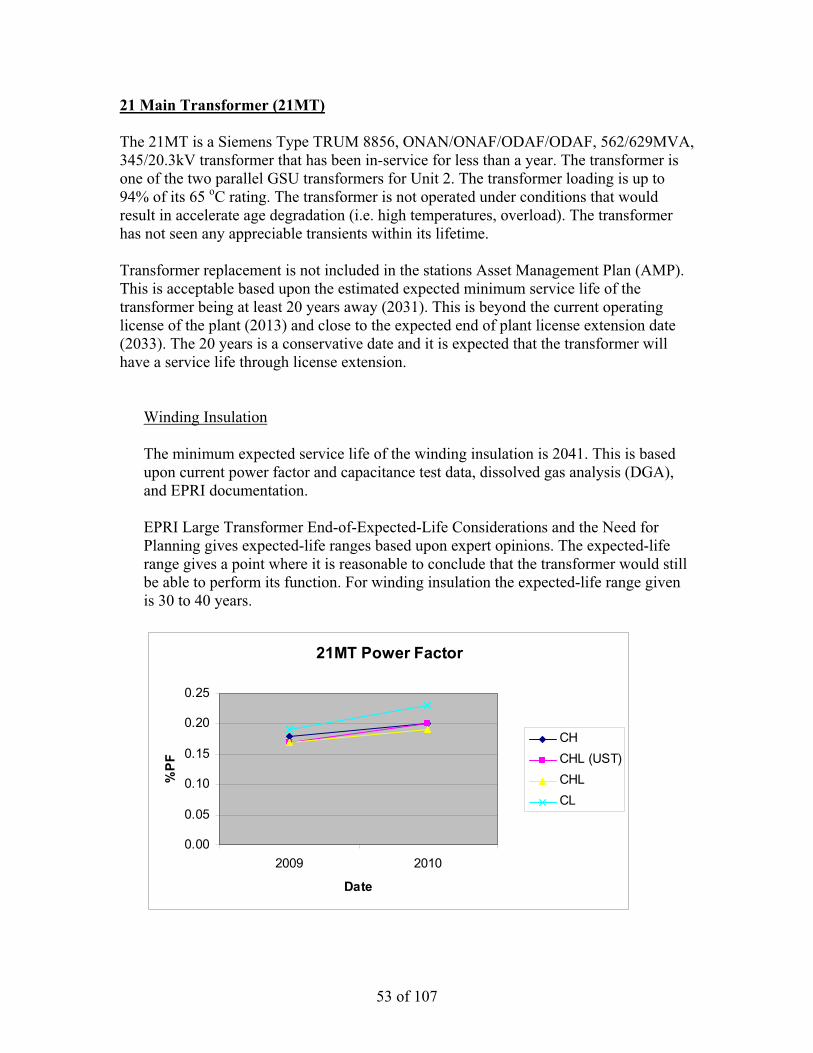
53 of 107
21 Main Transformer (21MT) The 21MT is a Siemens Type TRUM 8856, ONAN/ONAF/ODAF/ODAF, 562/629MVA, 345/20.3kV transformer that has been in-service for less than a year. The transformer is one of the two parallel GSU transformers for Unit 2. The transformer loading is up to 94% of its 65 oC rating. The transformer is not operated under conditions that would result in accelerate age degradation (i.e. high temperatures, overload). The transformer has not seen any appreciable transients within its lifetime. Transformer replacement is not included in the stations Asset Management Plan (AMP). This is acceptable based upon the estimated expected minimum service life of the transformer being at least 20 years away (2031). This is beyond the current operating license of the plant (2013) and close to the expected end of plant license extension date (2033). The 20 years is a conservative date and it is expected that the transformer will have a service life through license extension.
Winding Insulation The minimum expected service life of the winding insulation is 2041. This is based upon current power factor and capacitance test data, dissolved gas analysis (DGA), and EPRI documentation. EPRI Large Transformer End-of-Expected-Life Considerations and the Need for Planning gives expected-life ranges based upon expert opinions. The expected-life range gives a point where it is reasonable to conclude that the transformer would still be able to perform its function. For winding insulation the expected-life range given is 30 to 40 years.
21MT Power Factor
0.00
0.05
0.10
0.15
0.20
0.25
2009 2010
Date
%P
F
CH CHL (UST)CHL CL

54 of 107
The power factor trend does not indicate any accelerated or adverse anomalies in the transformers insulating system. The power factor test is performed at most every four years. Based upon the trends in power factor the four year frequency is acceptable.
21MT Capacitance
0
10000
20000
30000
40000
50000
2009 2010
Date
pF
CH CHL (UST)CHL CL
The capacitance trend does not indicate any adverse changes in the geometry of the windings. The capacitance test is performed at most every four years. Based upon the trends in capacitance the four year frequency is acceptable.
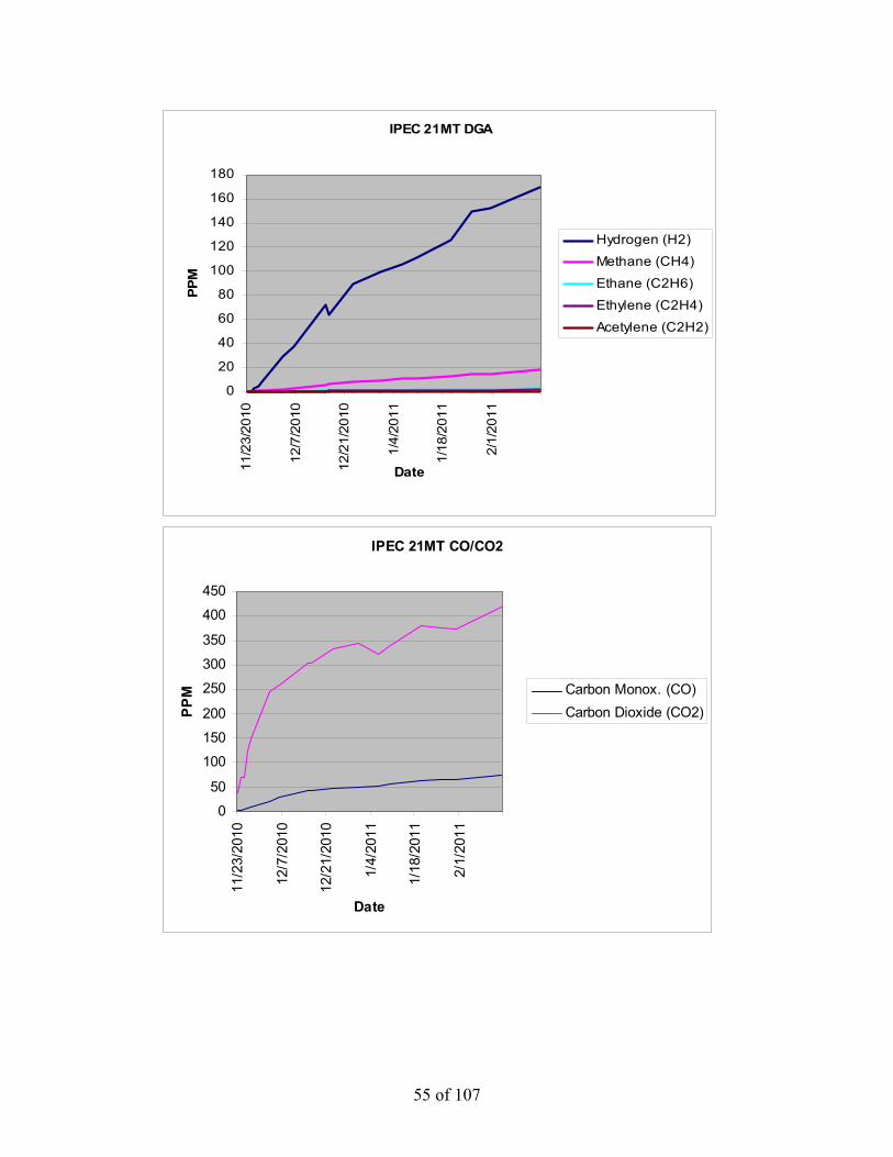
55 of 107
IPEC 21MT DGA
0
20
40
60
80
100
120
140
160
180
11/2
3/20
10
12/7
/201
0
12/2
1/20
10
1/4/
2011
1/18
/201
1
2/1/
2011
Date
PPM
Hydrogen (H2)
Methane (CH4)
Ethane (C2H6)
Ethylene (C2H4)
Acetylene (C2H2)
IPEC 21MT CO/CO2
0
50
100
150
200
250
300
350
400
450
11/2
3/20
10
12/7
/201
0
12/2
1/20
10
1/4/
2011
1/18
/201
1
2/1/
2011
Date
PPM Carbon Monox. (CO)
Carbon Dioxide (CO2)

56 of 107
The DGA trend does not indicate any adverse conditions with the transformer winding insulation. It is noted that Hydrogen has been trending up since transformer installation. The trend is being monitored by System Engineering and the vendor. Per the vendor, is believed to be due to localized heating and is not an immediate concern. The transformer is being sampled on a monthly frequency. Based upon the trends in gases the monthly frequency is acceptable and within industry guidance.
Internal Bus Supports The minimum expected service life of the internal bus supports is 2031, based on the EPRI Large Transformer End-of-Expected-Life Considerations and the Need for Planning expected-life range. The expected-life range gives a point where it is reasonable to conclude that the transformer would still be able to perform its function. For internal bus supports the expected-life range given is 20 to 30 years. EPRI identifies the failure mechanism of internal bus supports as: failure due to being under-designed. Failures of bus supports could be indicated by arcing/tracking. The dissolved gas analysis does not indicate that arcing is occurring within the transformer. Arcing would be indicated by the presence of Acetylene (C2H2). There are no useful PM tasks for internal bus supports.
Core The minimum expected service life of the core is 2051, based on the following: Problems with transformer cores include: loss of ground, multiple grounds or looseness. Multiple grounds or loss of core ground would be determined through testing of the core ground. Testing of the core ground has been performed satisfactory. Looseness would be indicated by a change in 60Hz noise. While this is qualitative, there have been no reported changes in transformer noise by Operations or System Engineering. The transformer core ground is tested on at most a four year frequency. This task frequency is acceptable based upon the current condition of the transformer. The transformer is walked down at least daily by Operations and periodically by System Engineering. These task frequencies are acceptable based upon the current condition of the transformer.

57 of 107
Tank The minimum expected service life of the tank is 2051. This is based upon PM inspections of the tank along with Operations and System Engineering walkdowns. During these activities degradation to the tank would be documented via condition report (CR) and a work order (WO) would be written to correct the condition, if not corrected during the PM. The tank currently does not have any noted deficiencies that would reduce its expected service life. The transformer PM inspection is performed every two years and the transformer is walked down at least daily by Operations and periodically by System Engineering. These task frequencies are acceptable based upon the current condition of the transformer. EPRI Large Transformer End-of-Expected-Life Considerations and the Need for Planning gives an expected-life range of 40+ years for the tank. Bushings The minimum expected service life of the high voltage bushings is 2012. This is based upon the site operating experience with the bushings (CR-IP2-2011-06801). The bushings are Trench Type COTA, the same make and model as the bushing that failed in 21MT in November 2010. The bushing failed after approximately 4 ½ years of service life. Based on this it would be reasonable to conclude that the bushings would have a service life of at least 1 ½ years. It is expected that the bushings will be replaced in the next scheduled refueling outage (spring 2012). The minimum expected service life of the low voltage bushings is 2026. The Low voltage bushings are Siemens bushings. EPRI Large Transformer End-of-Expected-Life Considerations and the Need for Planning gives an expected-life range of > 15 years for the bushings.

58 of 107
21MT HV Bushing Power Factor
00.050.1
0.150.2
0.250.3
0.350.4
nameplate 8/4/2009 11/13/2010
Date tested
%P
F
H1H2H3
21MT HV Bushing Capacitance Test C1
430435440445450455460465
nameplate 8/4/2009 11/13/2010
Date tested
pF
H1H2H3

59 of 107
Hot Collar Test Results mA 8/4/2009 11/13/2010H0 0.0990 0.1010X1 0.2100 0.1860X2 0.2090 0.1810X3 0.2110 0.1840X4 0.2130 0.1810X5 0.2120 0.1810X6 0.2040 0.1840 Watts 8/4/2009 11/13/2010H0 0.0210 0.0250X1 0.0380 0.0160X2 0.0390 0.0160X3 0.0370 0.0170X4 0.0400 0.0190X5 0.0370 0.0190X6 0.0480 0.0180
The hot collar test results do not indicate that any of the bushings are degraded or are starting to show signs of degradation. The test results for each bushing type are comparable to each other, within the same test date. The bushings are tested on at most a four year frequency. Based upon the trend in test results the four year frequency is acceptable. Oil Pumps, Control Cabinet Devices, Tap Changer, Current Transformers and Protective Relays These types of subcomponents have been identified as single point vulnerabilities (SPV). The maintenance and mitigation strategies are addressed in the attached SPV review. This will ensure that these components do not exceed their expected service lives.

60 of 107
ANO GGNS IPEC JAF PLP PNPS RBS VY W3 SYSTEM: 345K
COMPONENT: 21MTRFR and 22MTRFR
DATE: 3/1/11
UNIT TRIP OR DERATE INITIATING COMPONENT (Specify if Unit Trip or Derate): Trip and Derate SINGLE POINT FAILURE VULNERABILITIES: Trip:
1. Internal Components (windings, insulation, core, oil) 2. Bushings 3. Current Transformers (CTs) 4. Lightning Arrestors (LAs) 5. Protective Relays (87/T21, 87/T22, 51N/T)
Derate:
1. Oil Pumps (88P-1, 88P-2) 2. Circuit Breakers (8-1, 8-2, 8-3, 8-4, 8-5, 8-6, 8-7, 8-8, 8-9, 8-10, 8-15, 8-16, 8-17, Pump Breakers,
Fan Breakers) 3. Contactors (3-1, 3-2, 27-3, 62-1) 4. Control Power Transformer (95-1) 5. Automatic Transfer Switch (83) 6. Loss of Oil
Reference Drawings: A208377, 2005MD0112, 2005MD0113, 2005MD0117, 9321-LL-3130 Sheets 5 and 6 PLANT OPERATING EXPERIENCE: • CR-IP2-2010-06801 (21 Main Transformer
Failure) • CR-IP3-2007-01834 (31 Main Transformer
Failure) • CR-IP2-2009-00959 (Loss of UAT Cooling due
to Coordination Issue)
INDUSTRY OPERATING EXPERIENCE: • SOER 10-1 (Large Power Transformer
Reliability) • IER L3-10-6 (Loss of Transformer Cooling due
to CPT Failure) • OE31908 (Partial Loss of Transformer Cooling
due to Damaged Plug Connector) • OE29135 and OE32417 (Loss of Transformer
Cooling due to CPT Failure caused by Contactor Failure)
• OE20943 (Loss of Transformer Cooling due to Coordination Issue)
• OE29330 (Loss of Transformer Cooling due Age Degraded MCCB Failing to Trip)
• OE14335 (Transformer Trip due to Gap Type LA Failure) also see INPO TR4-40.
• SEN 275 (HV Bushing Failure due to Failure at Test Tap)

61 of 107
MITIGATION STRATEGY(List proposed corrective actions, recommended implementation timeline, actions taken, actions pending, and document tracking number (i.e. PCRS, Work Order, Engineering Change Request, Modification). Attachment 9.5 provides sample SPF Mitigation Strategies.): Trip:
1. Internal Components (windings, insulation, core, oil)
• Continue with existing predictive electrical testing (power factor, capacitance, winding resistance, TTR, SFRA, etc.).
PMRQ: 50058621-08 / 50058584-06 Procedure: 2-XFR-006-ELC
• Continue with existing periodic oil samples (DGA, Oil Quality and Furans). Procedure: 0-CY-2655
• Continue with existing thermography scans. PMRQ: 22451-01 MWO: 198051
2. Bushings
• Continue with existing predictive electrical testing (power factor and capacitance) and
maintenance. PMRQ: 50058621-08 / 50058584-06 Procedure: 2-XFR-006-ELC
• Continue with existing thermography scans. PMRQ: 22451-01 MWO: 198051
• Continue with existing corona scans. PMRQ: 22452-01 MWO: 198052
3. Current Transformers (CTs)
• Continue with existing preventive maintenance.
PMRQ: 50058621-04 / 50058584-04 Procedure: 2-IC-PC-I-E-21MTRFR CT / 2-IC-PC-I-E-22MTRFR CT
4. Lightning Arrestors (LAs)
• Continue with existing preventive maintenance.
PMRQ: 50058621-02 Procedure: 0-ELC-400-LPS

62 of 107
5. Protective Relays (87/T21, 87/T22, 51N/T)
• Continue with existing periodic calibration of the relays.
PMRQs: 23218, 23219 and 50060320 MWOs: 51506915, 51507616 and 51506881
Derate:
1. Oil Pumps (88P-1, 88P-2)
• Periodic oil pump replacement was not included in the PM program for 22MTRFR. PMCR 101121 has been completed to implement the PM. (CA-21 of CR-IP2-2010-01985)
• Continue with existing periodic oil pump replacements. PMRQs: 50058621-05 / 50058584-11 MWOs: 51504131 / 265485
2. Circuit Breakers (8-1, 8-2, 8-3, 8-4, 8-5, 8-6, 8-7, 8-8, 8-9, 8-10, 8-15, 8-16, 8-17, Pump Breakers,
Fan Breakers)
• Continue with existing PM to cycle the breakers on a periodic basis. PMRQ: 50058621-08 / 50058584-06 Procedure: 2-XFR-006-ELC
• Continue with existing thermography scans. PMRQ: 22451-01 MWO: 198051
3. Contactors (3-1, 3-2, 27-3, 62-1)
• Continue with existing thermography scans. PMRQ: 22451-01 MWO: 198051
4. Control Power Transformer (95-1)
• Continue with existing thermography scans.
PMRQ: 22451-01 MWO: 198051
5. Automatic Transfer Switch (83)
• The PM procedure for the transformer (2-XFR-006-ELC) does not contain all of the
vendor recommended preventive maintenance for the transfer switch. CA-27 under CR-IP2-2010-01985 has been assigned to revise the procedure.

63 of 107
6. Loss of Oil
• Continue with existing preventive maintenance.
PMRQ: 50058621-08 / 50058584-06 Procedure: 2-XFR-006-ELC
• Continue with existing Operator rounds and System Engineering walkdowns. Overall a review was performed of the procedures and MWOs referenced for the SPVs. The review identified changes that can be made to the procedures that will enhance the maintenance of the SPVs. The procedure changes are associated with 2-XFR-006-ELC (Transformer PM), 2-IC-PC-I-E-21/22MTRFR and MWO 198051 (Thermography). CAs-27, 28 and 29 under CR-IP2-2010-01985 have been assigned to implement the changes. BASIS FOR CONCLUSIONS: The combination of preventive maintenance, predictive maintenance and procedure enhancements will mitigate the identified single point vulnerabilities. The current preventive maintenance performed on the transformer can adequately mitigate the identified vulnerabilities. The preventive maintenance in place is based upon, but not limited to, the following:
• EN-Transformer-Oil Immersed PM Basis Template • Vendor Manuals • Documentation contained in PM change requests (PMCRs).
The current predictive maintenance (i.e. electrical testing, oil sampling, thermography, corona) performed on the transformer can provide advance warning to mitigate degradation prior to equipment failure. The information gathered from predictive maintenance is used in System Engineering Monitoring and Trending and also feeds into the sites Transformer Long Range Plan. The predictive maintenance in place is based upon, but not limited to, the following fleet and industry guidance:
• EN-Transformer-Oil Immersed PM Basis Template • EN-EE-G-001 (Large Power Transformer Inspection Guidelines) • IEEE Std C57.104 (IEEE Guide for the Interpretation of Gases Generated in Oil-Immersed
Transformers) • IEEE Std C57.106 (IEEE Guide for Acceptance and Maintenance of Insulating Oil in
Equipment) • Doble Test Procedures Manual
The circuit breakers, contactors and CPT have a life expectancy that typically exceeds 20 years of operation. This life expectancy will be adequate for the remaining operating life of the plant and/or transformer. A search of applicable vendor information did not find any vendor specified maintenance or replacement frequencies for these devices.

64 of 107
22 Main Transformer (22MT) The 22MT is a Siemens Type TRUM 8856, ONAN/ONAF/ODAF/ODAF, 562/629MVA, 345/20.3kV transformer that has been in-service since 2006. The transformer is one of the two parallel GSU transformers for Unit 2. The transformer loading is up to 94% of its 65 oC rating. The transformer is not operated under conditions that would result in accelerate age degradation (i.e. high temperatures, overload). While the transformer has seen transients within its lifetime (i.e. failure of 21 Main Transformer), there does not appear to be a correlating reduction in expected service life from them. Transformer replacement is not included in the stations Asset Management Plan (AMP). This is acceptable based upon the estimated expected minimum service life of the transformer being at least 15 years away (2026). This is beyond the current operating license of the plant (2013) and close to the expected end of plant license extension date (2033). The 15 years is a conservative date and it is expected that the transformer will have a service life through license extension.
Winding Insulation The minimum expected service life of the winding insulation is 2036. This is based upon current power factor and capacitance test data, dissolved gas analysis (DGA), furanic compound analysis and EPRI documentation. EPRI Large Transformer End-of-Expected-Life Considerations and the Need for Planning gives expected-life ranges based upon expert opinions. The expected-life range gives a point where it is reasonable to conclude that the transformer would still be able to perform its function. For winding insulation the expected-life range given is 30 to 40 years.
22MT Power Factor
00.050.1
0.150.2
0.250.3
0.350.4
0.45
2006 2007 2008 2009 2010
Date
%P
F
CH CHL (UST)CHL CL

65 of 107
The power factor trend does not indicate any accelerated or adverse anomalies in the transformers insulating system. The power factor test is performed at most every four years. Based upon the trends in power factor the four year frequency is acceptable.
22MT Capacitance
0
10000
20000
30000
40000
50000
2006 2007 2008 2009 2010
Date
pF
CH CHL (UST)CHL CL
The capacitance trend does not indicate any adverse changes in the geometry of the windings. The capacitance test is performed at most every four years. Based upon the trends in capacitance the four year frequency is acceptable.

66 of 107
IPEC 22MT DGA
0
20
40
60
80
100
120
140
160
12/3
0/20
09
2/28
/201
0
4/30
/201
0
6/30
/201
0
8/30
/201
0
10/3
0/20
10
12/3
0/20
10Date
PPM
Hydrogen (H2)
Methane (CH4)
Ethane (C2H6)
Ethylene (C2H4)Acetylene (C2H2)
IPEC 22MT CO/CO2
0
1000
2000
3000
4000
5000
6000
12/3
0/20
09
2/28
/201
0
4/30
/201
0
6/30
/201
0
8/30
/201
0
10/3
0/20
10
12/3
0/20
10
Date
PPM
Carbon Monox. (CO)
Carbon Dioxide(CO2)
The DGA trend does not indicate any adverse conditions with the transformer winding insulation. Although gases are present the trends are stable.
The transformer is being sampled on a monthly frequency. Based upon the trends in gases the monthly frequency is acceptable and within industry guidance.

67 of 107
Furanic Compound Test Results
Sample Date
Top Oil Temp °C HMF FOL FAL AF MF
Overall FAL Rate
Estimated DP
Estimated Remaining Life to DP
200 Current
FAL Rate ug/L ug/L ug/L ug/L ug/L ug/L/Year % ug/L/Year 11/27/2010 67.4 < 1 < 1 11 < 1 < 1 2.75 988 100 0.00 11/26/2010 60 < 1 < 1 11 < 1 < 1 2.75 988 100 -898.46 11/25/2010 64 < 1 < 1 12 < 1 < 1 3.00 977 100 317.58 11/24/2010 40 < 1 < 1 11 < 1 < 1 2.75 988 100 -494.07 11/08/2010 9 18 < 1 32 < 1 2 8.00 856 95 85.16 09/01/2010 67 < 1 < 1 16 < 1 2 4.00 942 99 2.04 09/08/2009 61.2 < 1 < 1 14 < 1 1 4.67 958 99 2.02 09/11/2008 61 < 1 < 1 12 < 1 < 1 6.00 977 100 9.17 02/25/2008 42 1 < 1 7 < 1 < 1 3.50 1044 100 -4.59 09/19/2007 55 < 1 < 1 9 < 1 1 9.00 1013 100 -36.53 07/31/2007 < 1 < 1 14 < 1 2 14.00 958 99
The furanic compound levels and rates do not indicate that accelerated decomposition of insulation is occurring. Following the 21 Main Transformer failure on 11/7/10 the levels (HMF and FAL) did increase when the transformer was sampled de-energized. A confirmatory sample was taken on 11/24/10 and the levels returned to their approximate historic values.
The furan test is performed once a year. Based upon the trend in furans the yearly frequency is acceptable. Internal Bus Supports The minimum expected service life of the internal bus supports is 2026, based on the EPRI Large Transformer End-of-Expected-Life Considerations and the Need for Planning expected-life range. The expected-life range gives a point where it is reasonable to conclude that the transformer would still be able to perform its function. For internal bus supports the expected-life range given is 20 to 30 years. EPRI identifies the failure mechanism of internal bus supports as: failure due to being under-designed. Failures of bus supports could be indicated by arcing/tracking. The dissolved gas analysis does not indicate that arcing is occurring within the transformer. Arcing would be indicated by the presence of Acetylene (C2H2). There are no useful PM tasks for internal bus supports.

68 of 107
Core The minimum expected service life of the core is 2046, based on the following: Problems with transformer cores include: loss of ground, multiple grounds or looseness. Multiple grounds or loss of core ground would be determined through testing of the core ground. Testing of the core ground has been performed satisfactory. Looseness would be indicated by a change in 60Hz noise. While this is qualitative, there have been no reported changes in transformer noise by Operations or System Engineering. The transformer core ground is tested on at most a four year frequency. This task frequency is acceptable based upon the current condition of the transformer. The transformer is walked down at least daily by Operations and periodically by System Engineering. These task frequencies are acceptable based upon the current condition of the transformer. Tank The minimum expected service life of the tank is 2046. This is based upon PM inspections of the tank along with Operations and System Engineering walkdowns. During these activities degradation to the tank would be documented via condition report (CR) and a work order (WO) would be written to correct the condition, if not corrected during the PM. The tank currently does not have any noted deficiencies that would reduce its expected service life. The transformer PM inspection is performed every two years and the transformer is walked down at least daily by Operations and periodically by System Engineering. These task frequencies are acceptable based upon the current condition of the transformer. EPRI Large Transformer End-of-Expected-Life Considerations and the Need for Planning gives an expected-life range of 40+ years for the tank.

69 of 107
Bushings The following is written assuming high voltage bushing replacement in May 2011. The minimum expected service life of the high voltage bushings is 2012. This is based upon the site operating experience with the bushings (CR-IP2-2011-06801). The bushings are Trench Type COTA, the same make and model as the bushing that failed in 21MT in November 2010. The bushing failed after approximately 4 ½ years of service life. Based on this it would be reasonable to conclude that the bushings would have a service life of at least 1 year. It is expected that the bushings will be replaced in the next scheduled refueling outage (spring 2012). The minimum expected service life of the low voltage bushings is 2021. The Low voltage bushings are Siemens bushings. EPRI Large Transformer End-of-Expected-Life Considerations and the Need for Planning gives an expected-life range of > 15 years for the bushings.
22MT HV Bushing Power Factor
00.050.1
0.150.2
0.250.3
0.35
nameplate 5/4/2006 4/8/2008 11/11/2010
Date tested
%PF
H1H2H3
22MT HV Bushing Capacitance Test C1
434436438440442444446448450452
nameplate 5/4/2006 4/8/2008 11/11/2010
Date tested
pF
H1H2H3

70 of 107
Hot Collar Test Results mA 5/6/2006 4/8/2008 11/11/2010H0 0.1210X1 0.0195 0.1890 0.1760X2 0.0195 0.1880 0.1700X3 0.0197 0.1860 0.1750X4 0.0202 0.1850 0.1820X5 0.0196 0.1940 0.1790X6 0.0193 0.1980 0.1780 Watts 5/6/2006 4/8/2008 11/11/2010H0 0.0100X1 0.0026 0.0190 0.0210X2 0.0025 0.0210 0.0220X3 0.0026 0.0180 0.0200X4 0.0025 0.0180 0.0170X5 0.0027 0.0180 0.0210X6 0.0024 0.0180 0.0170
The hot collar test results do not indicate that any of the bushings are degraded or are starting to show signs of degradation. The test results for each bushing type are comparable to each other, within the same test date. The bushings are tested on at most a four year frequency. Based upon the trend in test results the four year frequency is acceptable. Oil Pumps, Control Cabinet Devices, Tap Changer, Current Transformers and Protective Relays These types of subcomponents have been identified as single point vulnerabilities (SPV). The maintenance and mitigation strategies are addressed in the attached SPV review. This will ensure that these components do not exceed their expected service lives.

71 of 107
ANO GGNS IPEC JAF PLP PNPS RBS VY W3 SYSTEM: 345K
COMPONENT: 21MTRFR and 22MTRFR
DATE: 3/1/11
UNIT TRIP OR DERATE INITIATING COMPONENT (Specify if Unit Trip or Derate): Trip and Derate SINGLE POINT FAILURE VULNERABILITIES: Trip:
1. Internal Components (windings, insulation, core, oil) 2. Bushings 3. Current Transformers (CTs) 4. Lightning Arrestors (LAs) 5. Protective Relays (87/T21, 87/T22, 51N/T)
Derate:
1. Oil Pumps (88P-1, 88P-2) 2. Circuit Breakers (8-1, 8-2, 8-3, 8-4, 8-5, 8-6, 8-7, 8-8, 8-9, 8-10, 8-15, 8-16, 8-17, Pump Breakers,
Fan Breakers) 3. Contactors (3-1, 3-2, 27-3, 62-1) 4. Control Power Transformer (95-1) 5. Automatic Transfer Switch (83) 6. Loss of Oil
Reference Drawings: A208377, 2005MD0112, 2005MD0113, 2005MD0117, 9321-LL-3130 Sheets 5 and 6 PLANT OPERATING EXPERIENCE: • CR-IP2-2010-06801 (21 Main Transformer
Failure) • CR-IP3-2007-01834 (31 Main Transformer
Failure) • CR-IP2-2009-00959 (Loss of UAT Cooling due
to Coordination Issue)
INDUSTRY OPERATING EXPERIENCE: • SOER 10-1 (Large Power Transformer
Reliability) • IER L3-10-6 (Loss of Transformer Cooling due
to CPT Failure) • OE31908 (Partial Loss of Transformer Cooling
due to Damaged Plug Connector) • OE29135 and OE32417 (Loss of Transformer
Cooling due to CPT Failure caused by Contactor Failure)
• OE20943 (Loss of Transformer Cooling due to Coordination Issue)
• OE29330 (Loss of Transformer Cooling due Age Degraded MCCB Failing to Trip)
• OE14335 (Transformer Trip due to Gap Type LA Failure) also see INPO TR4-40.
• SEN 275 (HV Bushing Failure due to Failure at Test Tap)

72 of 107
MITIGATION STRATEGY(List proposed corrective actions, recommended implementation timeline, actions taken, actions pending, and document tracking number (i.e. PCRS, Work Order, Engineering Change Request, Modification). Attachment 9.5 provides sample SPF Mitigation Strategies.): Trip:
1. Internal Components (windings, insulation, core, oil)
• Continue with existing predictive electrical testing (power factor, capacitance, winding resistance, TTR, SFRA, etc.).
PMRQ: 50058621-08 / 50058584-06 Procedure: 2-XFR-006-ELC
• Continue with existing periodic oil samples (DGA, Oil Quality and Furans). Procedure: 0-CY-2655
• Continue with existing thermography scans. PMRQ: 22451-01 MWO: 198051
2. Bushings
• Continue with existing predictive electrical testing (power factor and capacitance) and
maintenance. PMRQ: 50058621-08 / 50058584-06 Procedure: 2-XFR-006-ELC
• Continue with existing thermography scans. PMRQ: 22451-01 MWO: 198051
• Continue with existing corona scans. PMRQ: 22452-01 MWO: 198052
3. Current Transformers (CTs)
• Continue with existing preventive maintenance.
PMRQ: 50058621-04 / 50058584-04 Procedure: 2-IC-PC-I-E-21MTRFR CT / 2-IC-PC-I-E-22MTRFR CT
4. Lightning Arrestors (LAs)
• Continue with existing preventive maintenance.
PMRQ: 50058621-02 Procedure: 0-ELC-400-LPS

73 of 107
5. Protective Relays (87/T21, 87/T22, 51N/T)
• Continue with existing periodic calibration of the relays.
PMRQs: 23218, 23219 and 50060320 MWOs: 51506915, 51507616 and 51506881
Derate:
1. Oil Pumps (88P-1, 88P-2)
• Periodic oil pump replacement was not included in the PM program for 22MTRFR. PMCR 101121 has been completed to implement the PM. (CA-21 of CR-IP2-2010-01985)
• Continue with existing periodic oil pump replacements. PMRQs: 50058621-05 / 50058584-11 MWOs: 51504131 / 265485
2. Circuit Breakers (8-1, 8-2, 8-3, 8-4, 8-5, 8-6, 8-7, 8-8, 8-9, 8-10, 8-15, 8-16, 8-17, Pump Breakers,
Fan Breakers)
• Continue with existing PM to cycle the breakers on a periodic basis. PMRQ: 50058621-08 / 50058584-06 Procedure: 2-XFR-006-ELC
• Continue with existing thermography scans. PMRQ: 22451-01 MWO: 198051
3. Contactors (3-1, 3-2, 27-3, 62-1)
• Continue with existing thermography scans. PMRQ: 22451-01 MWO: 198051
4. Control Power Transformer (95-1)
• Continue with existing thermography scans.
PMRQ: 22451-01 MWO: 198051
5. Automatic Transfer Switch (83)
• The PM procedure for the transformer (2-XFR-006-ELC) does not contain all of the
vendor recommended preventive maintenance for the transfer switch. CA-27 under CR-IP2-2010-01985 has been assigned to revise the procedure.

74 of 107
6. Loss of Oil
• Continue with existing preventive maintenance.
PMRQ: 50058621-08 / 50058584-06 Procedure: 2-XFR-006-ELC
• Continue with existing Operator rounds and System Engineering walkdowns. Overall a review was performed of the procedures and MWOs referenced for the SPVs. The review identified changes that can be made to the procedures that will enhance the maintenance of the SPVs. The procedure changes are associated with 2-XFR-006-ELC (Transformer PM), 2-IC-PC-I-E-21/22MTRFR and MWO 198051 (Thermography). CAs-27, 28 and 29 under CR-IP2-2010-01985 have been assigned to implement the changes. BASIS FOR CONCLUSIONS: The combination of preventive maintenance, predictive maintenance and procedure enhancements will mitigate the identified single point vulnerabilities. The current preventive maintenance performed on the transformer can adequately mitigate the identified vulnerabilities. The preventive maintenance in place is based upon, but not limited to, the following:
• EN-Transformer-Oil Immersed PM Basis Template • Vendor Manuals • Documentation contained in PM change requests (PMCRs).
The current predictive maintenance (i.e. electrical testing, oil sampling, thermography, corona) performed on the transformer can provide advance warning to mitigate degradation prior to equipment failure. The information gathered from predictive maintenance is used in System Engineering Monitoring and Trending and also feeds into the sites Transformer Long Range Plan. The predictive maintenance in place is based upon, but not limited to, the following fleet and industry guidance:
• EN-Transformer-Oil Immersed PM Basis Template • EN-EE-G-001 (Large Power Transformer Inspection Guidelines) • IEEE Std C57.104 (IEEE Guide for the Interpretation of Gases Generated in Oil-Immersed
Transformers) • IEEE Std C57.106 (IEEE Guide for Acceptance and Maintenance of Insulating Oil in
Equipment) • Doble Test Procedures Manual
The circuit breakers, contactors and CPT have a life expectancy that typically exceeds 20 years of operation. This life expectancy will be adequate for the remaining operating life of the plant and/or transformer. A search of applicable vendor information did not find any vendor specified maintenance or replacement frequencies for these devices.

75 of 107
31 Main Transformer (31MT) The 31MT is a Smit Nymegen, OA/FA/FA, 485/607MVA, 345/20.3kV transformer that has been in-service since 2007. The transformer is one of the two parallel GSU transformers for Unit 3. The transformer loading is up to 88% of its 65 oC rating. The transformer is not operated under conditions that would result in accelerate age degradation (i.e. high temperatures, overload). The transformer has not seen any notable transients within its life time. Transformer replacement is not included in the stations Asset Management Plan (AMP). This is acceptable based upon the estimated expected minimum service life of the transformer being at least 15 years away (2026). This is beyond the current operating license of the plant (2015) and close to the expected end of plant license extension date (2035). The 15 years is a conservative date and it is expected that the transformer will have a service life through license extension.
Winding Insulation The minimum expected service life of the winding insulation is 2037. This is based upon current power factor and capacitance test data, dissolved gas analysis (DGA), furanic compound analysis and EPRI documentation. EPRI Large Transformer End-of-Expected-Life Considerations and the Need for Planning gives expected-life ranges based upon expert opinions. The expected-life range gives a point where it is reasonable to conclude that the transformer would still be able to perform its function. For winding insulation the expected-life range given is 30 to 40 years.

76 of 107
31MT Power Factor
00.05
0.10.15
0.20.25
0.30.35
0.4
2007 2008 2009 2010 2011
Date tested
%PF
CHCHL(UST)CHLCL
The power factor trend does not indicate any accelerated or adverse anomalies in the transformers insulating system. The power factor test is performed at most every four years. Based upon the trends in power factor the four year frequency is acceptable.

77 of 107
31MT Capacitance
0
5000
10000
15000
20000
25000
30000
35000
2007 2008 2009 2010 2011
Date tested
pF
CHCHL(UST)CHLCL
The capacitance trend does not indicate any adverse changes in the geometry of the windings. In 2011 all six of the low voltage bushings were replaced, thus resulting in the reduction in capacitance. The capacitance test is performed at most every four years. Based upon the trends in capacitance the four year frequency is acceptable.

78 of 107
IPEC 31MT DGA
05
1015202530354045
2/25
/200
9
5/25
/200
9
8/25
/200
9
11/2
5/20
09
2/25
/201
0
5/25
/201
0
8/25
/201
0
11/2
5/20
10
2/25
/201
1
Date
PPM
Hydrogen (H2)Methane (CH4)Ethane (C2H6)Ethylene (C2H4)Acetylene (C2H2)
IPEC 31MT CO/CO2
0.0
500.0
1000.0
1500.0
2000.0
2500.0
3000.0
3500.0
4000.0
4500.0
5000.0
2/25
/09
4/25
/09
6/25
/09
8/25
/09
10/2
5/09
12/2
5/09
2/25
/10
4/25
/10
6/25
/10
8/25
/10
10/2
5/10
12/2
5/10
2/25
/11
Date
PPM
CarbonMonox.(CO)
CarbonDioxide(CO2)
The DGA trend does not indicate any adverse conditions with the transformer winding insulation. Although gases are present the trends are stable.
The transformer is being sampled on a monthly frequency. Based upon the trends in gases the monthly frequency is acceptable and within industry guidance.

79 of 107
Furanic Compound Test Results
Sample Date
Top Oil Temp °C HMF FOL FAL AF MF
Overall FAL Rate
Estimated DP
Estimated Remaining Life to DP
200 Current
FAL Rate ug/L ug/L ug/L ug/L ug/L ug/L/Year % ug/L/Year 03/30/2011 < 1 < 1 7 < 1 5 0.32 1044 100 -73.12 03/10/2011 6 < 1 < 1 11 < 1 5 0.50 988 100 0.00 11/15/2010 66 < 1 < 1 11 < 1 5 0.52 988 100 0.00 09/01/2010 76 < 1 < 1 11 < 1 < 1 0.52 988 100 2.12 09/21/2009 62 < 1 3 9 < 1 < 1 0.45 1013 100 -0.97 09/11/2008 66 1 < 1 10 < 1 < 1 0.53 1000 100 9.16 02/25/2008 54 3 < 1 5 < 1 < 1 0.26 1086 100 6.88 09/19/2007 61 < 1 < 1 2 < 1 < 1 0.11 1200 100 -51.25 07/24/2007 65 < 1 < 1 10 20 < 1 0.56 1000 100
The furanic compound levels and rates do not indicate that accelerated decomposition of insulation is occurring.
The estimated DP does not indicate that the transformer insulation is at the end of its useful life (DP 200). It is acknowledged that the current estimated DP may be higher than actual due to oil processing over the life of the transformer. While the estimated DP over the life of the transformer is not known, it is not believed that it would contribute to the current estimated DP being anywhere close to end of useful life.
The furan test is performed once a year. Based upon the trend in furans the yearly frequency is acceptable. Internal Bus Supports The minimum expected service life of the internal bus supports is 2026, based on the EPRI Large Transformer End-of-Expected-Life Considerations and the Need for Planning expected-life range. The expected-life range gives a point where it is reasonable to conclude that the transformer would still be able to perform its function. For internal bus supports the expected-life range given is 20 to 30 years. EPRI identifies the failure mechanism of internal bus supports as: failure due to being under-designed. Failures of bus supports could be indicated by arcing/tracking. The dissolved gas analysis does not indicate that arcing is occurring within the transformer. Arcing would be indicated by the presence of Acetylene (C2H2). There are no useful PM tasks for internal bus supports.

80 of 107
Core The minimum expected service life of the core is 2047, based on the following: Problems with transformer cores include: loss of ground, multiple grounds or looseness. Multiple grounds would be indicated by overheating through DGA. The DGA does not indicate that overheating is occurring. Loss of core ground would be indicated by arcing or a significant decrease in CL capacitance, neither of these conditions exists. Looseness would be indicated by a change in 60Hz noise. While this is qualitative, there have been no reported changes in transformer noise by Operations or System Engineering. The transformer is being sampled for DGA on a monthly frequency. Based upon the trends in gases the monthly frequency is acceptable and within industry guidance. The capacitance test is performed at most every four years. Based upon the trends in capacitance the four year frequency is acceptable. The transformer is walked down at least daily by Operations and periodically by System Engineering. These task frequencies are acceptable based upon the current condition of the transformer. Note: The transformer core ground is not accessible from outside of the tank. Tank The minimum expected service life of the tank is 2047. This is based upon PM inspections of the tank along with Operations and System Engineering walkdowns. During these activities degradation to the tank would be documented via condition report (CR) and a work order (WO) would be written to correct the condition, if not corrected during the PM. The tank currently does not have any noted deficiencies that would reduce its expected service life. The transformer PM inspection is performed every two years and the transformer is walked down at least daily by Operations and periodically by System Engineering. These task frequencies are acceptable based upon the current condition of the transformer. EPRI Large Transformer End-of-Expected-Life Considerations and the Need for Planning gives an expected-life range of 40+ years for the tank.

81 of 107
Bushings
The minimum expected service life of the high voltage bushings is 2022 and the low voltage bushings is 2026. The high voltage bushings are Felten & Guilleaume Type OTFa and the low voltage bushings are ABB Type T. EPRI Large Transformer End-of-Expected-Life Considerations and the Need for Planning gives an expected-life range of > 15 years for the bushings.
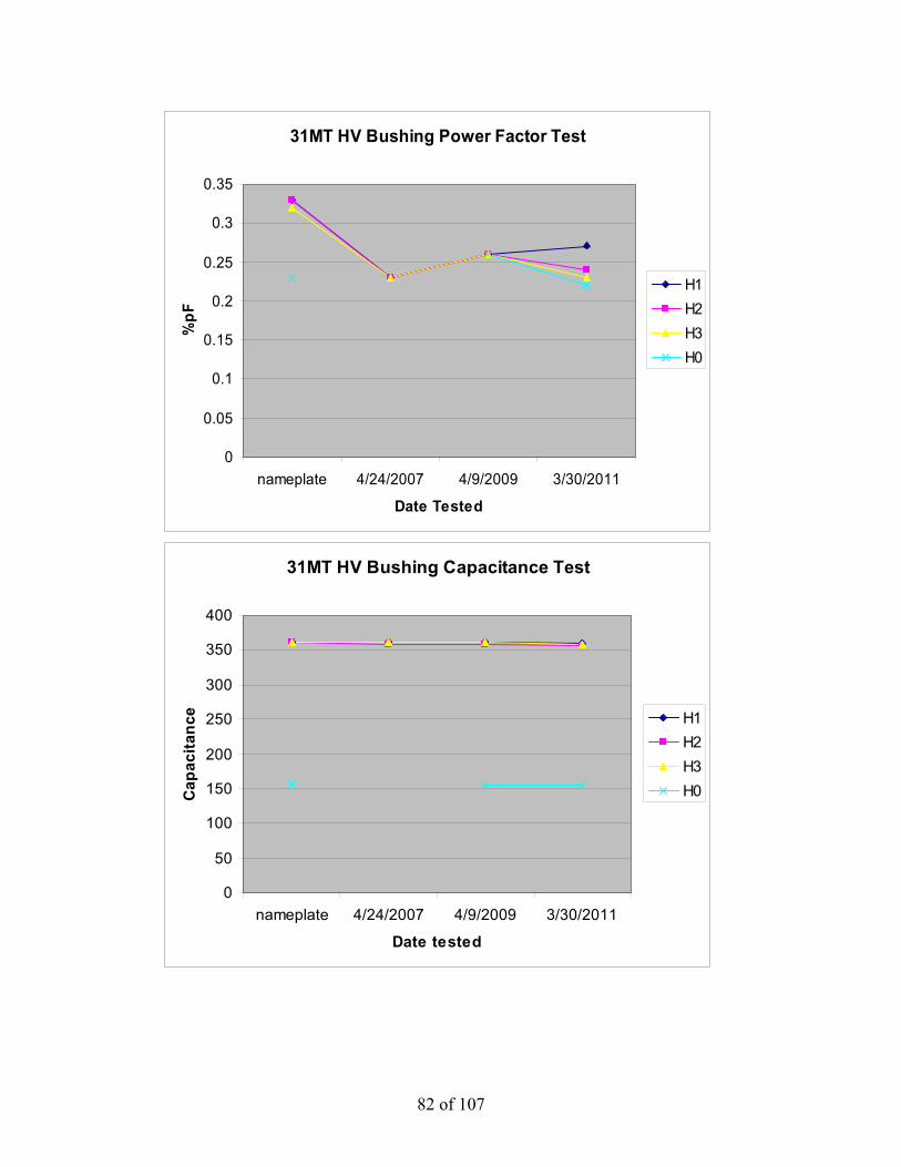
82 of 107
31MT HV Bushing Power Factor Test
0
0.05
0.1
0.15
0.2
0.25
0.3
0.35
nameplate 4/24/2007 4/9/2009 3/30/2011
Date Tested
%pF
H1H2H3H0
31MT HV Bushing Capacitance Test
0
50
100
150
200
250
300
350
400
nameplate 4/24/2007 4/9/2009 3/30/2011
Date tested
Cap
acita
nce H1
H2H3H0

83 of 107
31MT LV Bushing Power Factor Test
0.00
0.05
0.10
0.15
0.20
0.25
0.30
0.35
0.40
nameplate 3/30/2011
Date Tested
%pF
X1X2X3X4X5X6
31MT LV Bushing Capacitance Test
750
760
770
780
790
800
810
820
830
840
nameplate 3/30/2011
Date tested
Cap
acita
nce
X1X2X3X4X5X6

84 of 107
The test results for the high and low voltage bushings do not indicate that any of the bushings are degraded or are starting to show signs of degradation. The bushings are tested on at most a four year frequency. Based upon the trend in test results the four year frequency is acceptable. Oil Pumps, Control Cabinet Devices, Tap Changer, Current Transformers and Protective Relays These types of subcomponents have been identified as single point vulnerabilities (SPV). The maintenance and mitigation strategies are addressed in the attached SPV review. This will ensure that these components do not exceed their expected service lives.
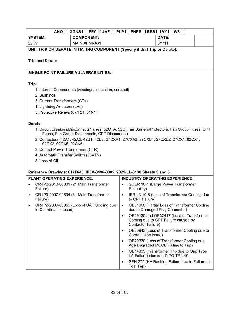
85 of 107
ANO GGNS IPEC JAF PLP PNPS RBS VY W3 SYSTEM: 22KV
COMPONENT: MAIN XFMR#31
DATE: 3/1/11
UNIT TRIP OR DERATE INITIATING COMPONENT (Specify if Unit Trip or Derate): Trip and Derate SINGLE POINT FAILURE VULNERABILITIES: Trip:
1. Internal Components (windings, insulation, core, oil) 2. Bushings 3. Current Transformers (CTs) 4. Lightning Arrestors (LAs) 5. Protective Relays (87/T21, 51N/T)
Derate:
1. Circuit Breakers/Disconnects/Fuses (52CTA, 52C, Fan Starters/Protectors, Fan Group Fuses, CPT Fuses, Fan Group Disconnects, CPT Disconnect)
2. Contactors (42A1, 42A2, 42B1, 42B2, 27CXA1, 27CXA2, 27CXB1, 27CXB2, 27CX1, 02CX1, 02CX2, 02CX5, 02CX6)
3. Control Power Transformer (CTR) 4. Automatic Transfer Switch (83ATS) 5. Loss of Oil
Reference Drawings: 617F645, IP3V-0496-0005, 9321-LL-3130 Sheets 5 and 6 PLANT OPERATING EXPERIENCE: • CR-IP2-2010-06801 (21 Main Transformer
Failure) • CR-IP3-2007-01834 (31 Main Transformer
Failure) • CR-IP2-2009-00959 (Loss of UAT Cooling due
to Coordination Issue)
INDUSTRY OPERATING EXPERIENCE: • SOER 10-1 (Large Power Transformer
Reliability) • IER L3-10-6 (Loss of Transformer Cooling due
to CPT Failure) • OE31908 (Partial Loss of Transformer Cooling
due to Damaged Plug Connector) • OE29135 and OE32417 (Loss of Transformer
Cooling due to CPT Failure caused by Contactor Failure)
• OE20943 (Loss of Transformer Cooling due to Coordination Issue)
• OE29330 (Loss of Transformer Cooling due Age Degraded MCCB Failing to Trip)
• OE14335 (Transformer Trip due to Gap Type LA Failure) also see INPO TR4-40.
• SEN 275 (HV Bushing Failure due to Failure at Test Tap)

86 of 107
MITIGATION STRATEGY(List proposed corrective actions, recommended implementation timeline, actions taken, actions pending, and document tracking number (i.e. PCRS, Work Order, Engineering Change Request, Modification). Attachment 9.5 provides sample SPF Mitigation Strategies.): Trip:
1. Internal Components (windings, insulation, core, oil)
• Continue with existing predictive electrical testing (power factor, capacitance, winding resistance, TTR, SFRA, etc.).
PMRQ: 50069087-07 Procedure: 3-XFR-011-ELC
• Continue with existing periodic oil samples (DGA, Oil Quality and Furans). Procedure: 0-CY-2655
• Continue with existing thermography scans. PMRQ: 21885-01 MWO: 193374
2. Bushings
• Continue with existing predictive electrical testing (power factor and capacitance) and
maintenance. PMRQ: 50069087-07 Procedure: 3-XFR-011-ELC
• Continue with existing thermography scans. PMRQ: 21885-01 MWO: 193374
• Continue with existing corona scans. PMRQ: 21888-01 MWO: 193381
3. Current Transformers (CTs)
• Continue with existing preventive maintenance.
PMRQ: 50069087-02 Procedure: 3-IC-PC-I-E-31MTRFR CT
4. Lightning Arrestors (LAs)
• Continue with existing preventive maintenance.
PMRQ: 50068760-02, 50068761-02 and 50068762-02 Procedure: 0-ELC-400-LPS

87 of 107
5. Protective Relays (87/T21, 51N/T)
• Continue with existing periodic calibration of the relays.
PMRQs: 20907 and 50071301 MWOs: 51496487 and 51491790
Derate:
1. Circuit Breakers/Disconnects/Fuses (52CTA, 52C, Fan Breakers, Fan Group Fuses, CPT Fuses, Fan Group Disconnects, CPT Disconnect)
• Continue with existing PM to cycle the breakers on a periodic basis.
PMRQ: 50069087-07 Procedure: 3-XFR-011-ELC
• Continue with existing thermography scans. PMRQ: 21885-01 MWO: 193374
2. Contactors (42A1, 42A2, 42B1, 42B2, 27CXA1, 27CXA2, 27CXB1, 27CXB2, 27CX1, 02CX1, 02CX2, 02CX5, 02CX6)
• Continue with existing thermography scans.
PMRQ: 21885-01 MWO: 193374
3. Control Power Transformer (CTR)
• Continue with existing thermography scans.
PMRQ: 21885-01 MWO: 193374
4. Automatic Transfer Switch (83ATS)
• The PM procedure for the transformer (3-XFR-011-ELC) does not contain all of the
vendor recommended preventive maintenance for the transfer switch. CA-27 under CR-IP2-2010-01985 has been assigned to revise the procedure.
5. Loss of Oil
• Continue with existing preventive maintenance.
PMRQ: 50069087-07 Procedure: 3-XFR-011-ELC
• Continue with existing Operator rounds and System Engineering walkdowns.

88 of 107
Overall a review was performed of the procedures and MWOs referenced for the SPVs. The review identified changes that can be made to the procedures that will enhance the maintenance of the SPVs. The procedure changes are associated with 3-XFR-011-ELC (Transformer PM), 3-IC-PC-I-E-31MTRFR CT and MWO 193374 (Thermography). CAs-27, 28 and 29 under CR-IP2-2010-01985 have been assigned to implement the changes.
BASIS FOR CONCLUSIONS: The combination of preventive maintenance, predictive maintenance and procedure enhancements will mitigate the identified single point vulnerabilities. The current preventive maintenance performed on the transformer can adequately mitigate the identified vulnerabilities. The preventive maintenance in place is based upon, but not limited to, the following:
• EN-Transformer-Oil Immersed PM Basis Template • Vendor Manuals • Documentation contained in PM change requests (PMCRs).
The current predictive maintenance (i.e. electrical testing, oil sampling, thermography, corona) performed on the transformer can provide advance warning to mitigate degradation prior to equipment failure. The information gathered from predictive maintenance is used in System Engineering Monitoring and Trending and also feeds into the sites Transformer Long Range Plan. The predictive maintenance in place is based upon, but not limited to, the following fleet and industry guidance:
• EN-Transformer-Oil Immersed PM Basis Template • EN-EE-G-001 (Large Power Transformer Inspection Guidelines) • IEEE Std C57.104 (IEEE Guide for the Interpretation of Gases Generated in Oil-Immersed
Transformers) • IEEE Std C57.106 (IEEE Guide for Acceptance and Maintenance of Insulating Oil in
Equipment) • Doble Test Procedures Manual
The circuit breakers, disconnects, motor starter/protectors, fuses, contactors and CPT have a life expectancy that typically exceeds 20 years of operation. This life expectancy will be adequate for the remaining operating life of the plant and/or transformer. A search of applicable vendor information did not find any vendor specified maintenance or replacement frequencies for these devices.

89 of 107
32 Main Transformer (32MT) The 32MT is a General Electric, OA/FOA/FOA, 542/607MVA, 345/20.3kV transformer that has been in-service for 25 Years. The transformer is one of the two parallel GSU transformers for Unit 3. The transformer loading is up to 88% of its 65 oC rating. The transformer is not operated under conditions that would result in accelerate age degradation (i.e. high temperatures, overload). While the transformer has seen transients within its lifetime (i.e. failure of 31 Main Transformer in 2007), there does not appear to be a correlating reduction in expected service life from them. Transformer replacement is in the stations Asset Management Plan (AMP) for 2017 (SIPD 731). This date is adequate for the estimated expected service life of the transformer and subcomponents.
Winding Insulation The minimum expected service life of the winding insulation is 2017. This is based upon current power factor and capacitance test data, dissolved gas analysis (DGA) and furanic compound analysis.
32MT Power Factor
0
0.050.1
0.150.2
0.25
0.30.35
0.4
2007 2008 2009 2010 2011
Date tested
%P
F
CHCHL(UST)CHLCL
The power factor trend does not indicate any accelerated or adverse anomalies in the transformers insulating system. The power factor test is performed at most every four years. Based upon the trends in power factor the four year frequency is acceptable.
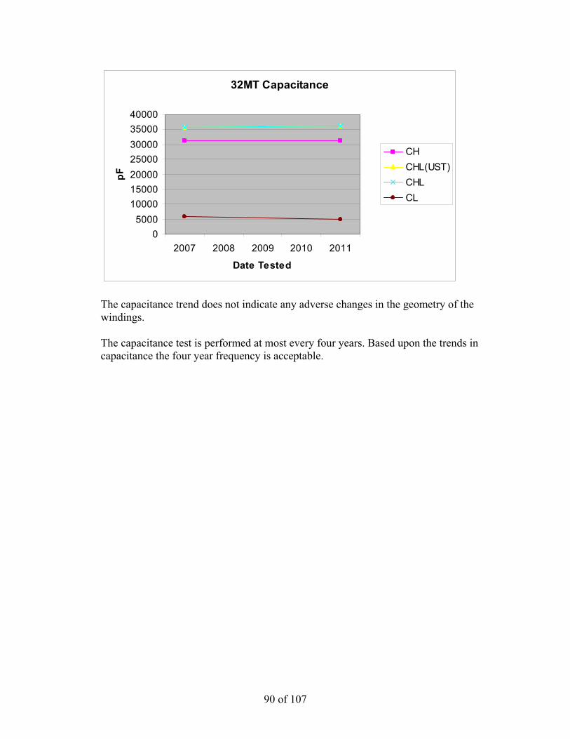
90 of 107
32MT Capacitance
05000
10000150002000025000300003500040000
2007 2008 2009 2010 2011
Date Tested
pF
CHCHL(UST)CHLCL
The capacitance trend does not indicate any adverse changes in the geometry of the windings. The capacitance test is performed at most every four years. Based upon the trends in capacitance the four year frequency is acceptable.

91 of 107
IPEC 32MT DGA
0
10
20
30
40
50
60
70
80
90
2/25
/200
9
4/25
/200
9
6/25
/200
9
8/25
/200
9
10/2
5/20
09
12/2
5/20
09
2/25
/201
0
4/25
/201
0
6/25
/201
0
8/25
/201
0
10/2
5/20
10
12/2
5/20
10
2/25
/201
1
Date
PPM
Hydrogen (H2)
Methane (CH4)
Ethane (C2H6)
Ethylene (C2H4)
Acetylene (C2H2)
IPEC 32MT CO/CO2
0
500
1000
1500
2000
2500
3000
3500
4000
4500
2/25
/200
9
5/25
/200
9
8/25
/200
9
11/2
5/20
09
2/25
/201
0
5/25
/201
0
8/25
/201
0
11/2
5/20
10
2/25
/201
1
Date
PPM Carbon Monox. (CO)
Carbon Dioxide (CO2)
The gassing in the transformer is trending stable and along with the transformers historic signature. The Rogers Ratio method was used to evaluate the gases, and the method suggests that the transformer is operating normally. The Duval Triangle was also used and Duval suggests that the source of gassing may be related to a low temperature thermal condition (< 300 oC). At this point in time is not believed that the gassing condition will result in a winding insulation service life of less than 2017.
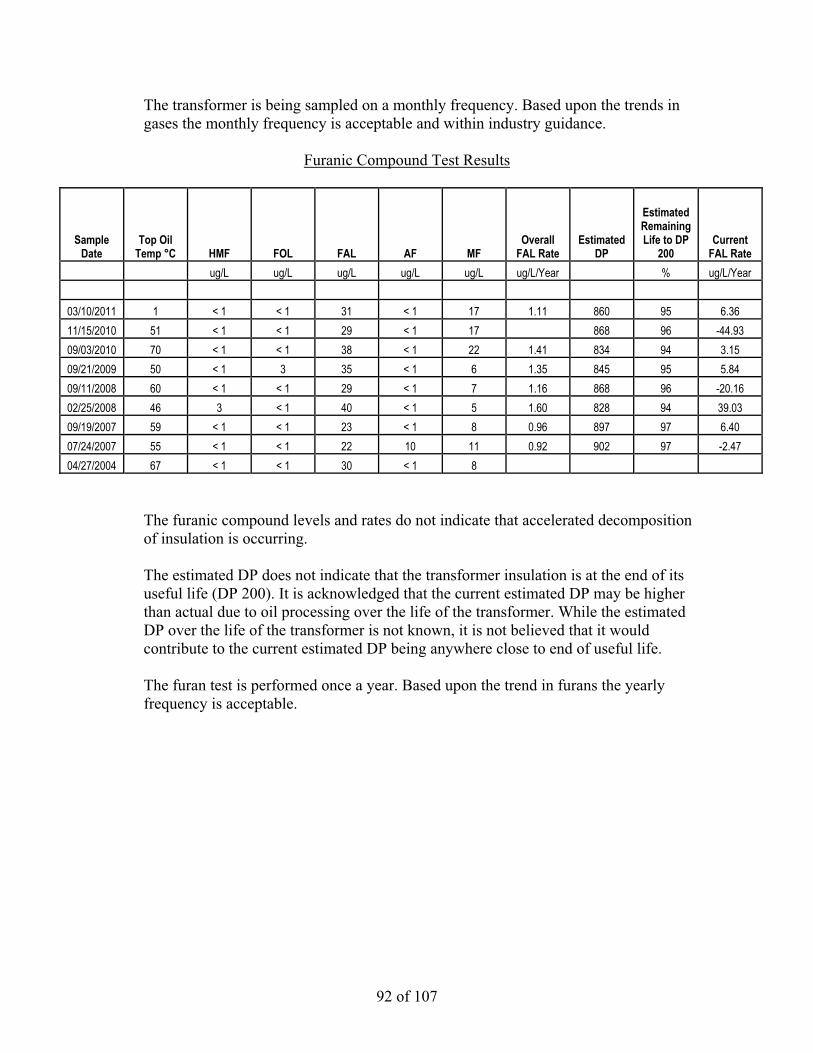
92 of 107
The transformer is being sampled on a monthly frequency. Based upon the trends in gases the monthly frequency is acceptable and within industry guidance.
Furanic Compound Test Results
Sample Date
Top Oil Temp °C HMF FOL FAL AF MF
Overall FAL Rate
Estimated DP
Estimated Remaining Life to DP
200 Current
FAL Rate ug/L ug/L ug/L ug/L ug/L ug/L/Year % ug/L/Year 03/10/2011 1 < 1 < 1 31 < 1 17 1.11 860 95 6.36 11/15/2010 51 < 1 < 1 29 < 1 17 868 96 -44.93 09/03/2010 70 < 1 < 1 38 < 1 22 1.41 834 94 3.15 09/21/2009 50 < 1 3 35 < 1 6 1.35 845 95 5.84 09/11/2008 60 < 1 < 1 29 < 1 7 1.16 868 96 -20.16 02/25/2008 46 3 < 1 40 < 1 5 1.60 828 94 39.03 09/19/2007 59 < 1 < 1 23 < 1 8 0.96 897 97 6.40 07/24/2007 55 < 1 < 1 22 10 11 0.92 902 97 -2.47 04/27/2004 67 < 1 < 1 30 < 1 8
The furanic compound levels and rates do not indicate that accelerated decomposition of insulation is occurring. The estimated DP does not indicate that the transformer insulation is at the end of its useful life (DP 200). It is acknowledged that the current estimated DP may be higher than actual due to oil processing over the life of the transformer. While the estimated DP over the life of the transformer is not known, it is not believed that it would contribute to the current estimated DP being anywhere close to end of useful life. The furan test is performed once a year. Based upon the trend in furans the yearly frequency is acceptable.

93 of 107
Internal Bus Supports The minimum expected service life of the internal bus supports is 2017, based on the following: EPRI identifies the failure mechanism of internal bus supports as: failure due to being under-designed. A search of Doble and INPO did not reveal any operating experience or Westinghouse service advisories that identify the bus supports in the transformer as being undersized. Failures of bus supports are also indicated by arcing/tracking. The dissolved gas analysis does not indicate that arcing is occurring within the transformer. Arcing would be indicated by the presence of Acetylene (C2H2). There are no useful PM tasks for internal bus supports. Core The minimum expected service life of the core is 2017, based on the following: Problems with transformer cores include: loss of ground, multiple grounds or looseness. Multiple grounds would be indicated by overheating through DGA. The DGA does not indicate that overheating is occurring. Loss of core ground would be indicated by arcing or a significant decrease in CL capacitance, neither of these conditions exists. Looseness would be indicated by a change in 60Hz noise. While this is qualitative, there have been no reported changes in transformer noise by Operations or System Engineering. The transformer is being sampled for DGA on a monthly frequency. Based upon the trends in gases the quarterly frequency is acceptable and within industry guidance. The capacitance test is performed at most every four years. Based upon the trends in capacitance the four year frequency is acceptable. The transformer is walked down at least daily by Operations and periodically by System Engineering. These task frequencies are acceptable based upon the current condition of the transformer. Note: The transformer core ground is not accessible from outside of the tank.

94 of 107
Tank The minimum expected service life of the tank is 2017. This is based upon PM inspections of the tank along with Operations and System Engineering walkdowns. During these activities degradation to the tank would be documented via condition report (CR) and a work order (WO) would be written to correct the condition, if not corrected during the PM. The tank currently does not have any noted deficiencies that would reduce its expected service life. The transformer PM inspection is performed every two years and the transformer is walked down at least daily by Operations and periodically by System Engineering. These task frequencies are acceptable based upon the current condition of the transformer.
Bushings The minimum expected service life of the bushings is 2017, based on the following: The high voltage bushings are ABB/Westinghouse Type O Plus C and the low voltage bushings are General Electric Type T.
32MT Bushing Power Factor
0.000.050.100.150.200.250.300.350.400.45
nameplate 4/2/2009 3/27/2011
Date tested
% P
F
H1H2H3H0X1X2X3X4X5X6

95 of 107
32MT Bushing Capacitance
050
100150200250300350400450500
nameplate 4/2/2009 3/27/2011
Date tested
pFH1H2H3H0X1X2X3X4X5X6
The power factor and capacitance test results do not indicate that any of the high or low voltage bushings are degraded or are starting to show signs of degradation.
The bushings are tested on at most a four year frequency. Based upon the trend in test results the four year frequency is acceptable. Oil Pumps, Control Cabinet Devices, Tap Changer, Current Transformers and Protective Relays These types of subcomponents have been identified as single point vulnerabilities (SPV). The maintenance and mitigation strategies are addressed in the attached SPV review. This will ensure that these components do not exceed their expected service lives.

96 of 107
ANO GGNS IPEC JAF PLP PNPS RBS VY W3 SYSTEM: 22KV
COMPONENT: MAIN XFMR#32
DATE: 3/1/11
UNIT TRIP OR DERATE INITIATING COMPONENT (Specify if Unit Trip or Derate): Trip and Derate SINGLE POINT FAILURE VULNERABILITIES: Trip:
1. Internal Components (windings, insulation, core, oil) 2. Bushings 3. Current Transformers (CTs) 4. Lightning Arrestors (LAs) 5. Protective Relays (87/T22, 51N/T)
Derate:
1. Oil Pumps (88QP-1-32MT, 88QP-2-32MT, 88QP-3-32MT, 88QP-4-32MT) 2. Circuit Breakers/Fuses (52-1 thru 52-6, Fan Breakers, CLF, CLF-1, FU-1, FU-2) 3. Contactors (4-1 thru 4-6, 2-1, 2-2, 27C, 27-1, 27-2, 74) 4. Control Power Transformer (CTR) 5. Automatic Transfer Switch (89) 6. Loss of Oil
Reference Drawings: 617F645, IP3V-0179-0007, 9321-LL-3130 Sheets 5 and 6 PLANT OPERATING EXPERIENCE: • CR-IP2-2010-06801 (21 Main Transformer
Failure) • CR-IP3-2007-01834 (31 Main Transformer
Failure) • CR-IP2-2009-00959 (Loss of UAT Cooling due
to Coordination Issue)
INDUSTRY OPERATING EXPERIENCE: • SOER 10-1 (Large Power Transformer
Reliability) • IER L3-10-6 (Loss of Transformer Cooling due
to CPT Failure) • OE31908 (Partial Loss of Transformer Cooling
due to Damaged Plug Connector) • OE29135 and OE32417 (Loss of Transformer
Cooling due to CPT Failure caused by Contactor Failure)
• OE20943 (Loss of Transformer Cooling due to Coordination Issue)
• OE29330 (Loss of Transformer Cooling due Age Degraded MCCB Failing to Trip)
• OE14335 (Transformer Trip due to Gap Type LA Failure) also see INPO TR4-40.
• SEN 275 (HV Bushing Failure due to Failure at Test Tap)

97 of 107
MITIGATION STRATEGY(List proposed corrective actions, recommended implementation timeline, actions taken, actions pending, and document tracking number (i.e. PCRS, Work Order, Engineering Change Request, Modification). Attachment 9.5 provides sample SPF Mitigation Strategies.): Trip:
1. Internal Components (windings, insulation, core, oil)
• Continue with existing predictive electrical testing (power factor, capacitance, winding resistance, TTR, SFRA, etc.).
PMRQ: 50069088-07 Procedure: 3-XFR-011-ELC
• Continue with existing periodic oil samples (DGA, Oil Quality and Furans). Procedure: 0-CY-2655
• Continue with existing thermography scans. PMRQ: 21885-01 MWO: 193374
2. Bushings
• Continue with existing predictive electrical testing (power factor and capacitance) and
maintenance. PMRQ: 50069088-07 Procedure: 3-XFR-011-ELC
• Continue with existing thermography scans. PMRQ: 21885-01 MWO: 193374
• Continue with existing corona scans. PMRQ: 21888-01 MWO: 193381
3. Current Transformers (CTs)
• Continue with existing preventive maintenance.
PMRQ: 50069088-02 Procedure: 3-IC-PC-I-E-32MTRFR CT
4. Lightning Arrestors (LAs)
• Continue with existing preventive maintenance.
PMRQ: 50068760-02, 50068761-02 and 50068762-02 Procedure: 0-ELC-400-LPS

98 of 107
5. Protective Relays (87/T22, 51N/T)
• Continue with existing periodic calibration of the relays.
PMRQs: 20908 and 50071301 MWOs: 51491948 and 51491790
Derate:
1. Oil Pumps (88QP-1-32MT, 88QP-2-32MT, 88QP-3-32MT, 88QP-4-32MT)
• Continue with existing periodic oil pump replacement. PMRQs: 50071618, 50071619, 50071620, 50071656 MWOs: 51493774, 51493775, 51493776, 51493777
2. Circuit Breakers/Disconnects/Fuses (52-1 thru 52-6, Fan Breakers, CLF, CLF-1, FU-1, FU-2)
• Continue with existing PM to cycle the breakers on a periodic basis.
PMRQ: 50069088-07 Procedure: 3-XFR-011-ELC
• Continue with existing thermography scans. PMRQ: 21885-01 MWO: 193374
3. Contactors (4-1 thru 4-6, 2-1, 2-2, 27C, 27-1, 27-2, 74)
• Continue with existing thermography scans. PMRQ: 21885-01 MWO: 193374
4. Control Power Transformer (CTR)
• Continue with existing thermography scans.
PMRQ: 21885-01 MWO: 193374
5. Automatic Transfer Switch (89)
• The PM procedure for the transformer (3-XFR-011-ELC) does not contain all of the
vendor recommended preventive maintenance for the transfer switch. CA-27 under CR-IP2-2010-01985 has been assigned to revise the procedure.

99 of 107
6. Loss of Oil
• Continue with existing preventive maintenance.
PMRQ: 50069087-07 Procedure: 3-XFR-011-ELC
• Continue with existing Operator rounds and System Engineering walkdowns. Overall a review was performed of the procedures and MWOs referenced for the SPVs. The review identified changes that can be made to the procedures that will enhance the maintenance of the SPVs. The procedure changes are associated with 3-XFR-011-ELC (Transformer PM), 3-IC-PC-I-E-32MTRFR CT and MWO 193374 (Thermography). CAs-27, 28 and 29 under CR-IP2-2010-01985 have been assigned to implement the changes. BASIS FOR CONCLUSIONS: The combination of preventive maintenance, predictive maintenance and procedure enhancements will mitigate the identified single point vulnerabilities. The current preventive maintenance performed on the transformer can adequately mitigate the identified vulnerabilities. The preventive maintenance in place is based upon, but not limited to, the following:
• EN-Transformer-Oil Immersed PM Basis Template • Vendor Manuals • Documentation contained in PM change requests (PMCRs).
The current predictive maintenance (i.e. electrical testing, oil sampling, thermography, corona) performed on the transformer can provide advance warning to mitigate degradation prior to equipment failure. The information gathered from predictive maintenance is used in System Engineering Monitoring and Trending and also feeds into the sites Transformer Long Range Plan. The predictive maintenance in place is based upon, but not limited to, the following fleet and industry guidance:
• EN-Transformer-Oil Immersed PM Basis Template • EN-EE-G-001 (Large Power Transformer Inspection Guidelines) • IEEE Std C57.104 (IEEE Guide for the Interpretation of Gases Generated in Oil-Immersed
Transformers) • IEEE Std C57.106 (IEEE Guide for Acceptance and Maintenance of Insulating Oil in
Equipment) • Doble Test Procedures Manual
The circuit breakers, fuses, contactors and CPT have a life expectancy that typically exceeds 20 years of operation. This life expectancy will be adequate for the remaining operating life of the plant and/or transformer. A search of applicable vendor information did not find any vendor specified maintenance or replacement frequencies for these devices.
100 of 107
Unit 3 GT Auto Transformer (GT Auto) The Unit 3 GT Auto is a Westinghouse Type SL, OA, 20MVA, 13.8/6.9kV transformer and has been in-service for 36 years (original plant equipment). The transformer provides the alternate off-site power source to the plant. The transformer is normally energized and lightly loaded (a couple of MW or less) while the plant is on-line. Higher loading does occur when the plant is in cold shutdown and the SAT is de-energized for maintenance. The transformer is not operated under conditions that would result in accelerate age degradation (i.e. high temperatures, overload). While the transformer may have seen transients within its lifetime (i.e. in plant motor failures), there does not appear to be a correlating reduction in expected service life from them. Transformer replacement is not included in the stations Asset Management Plan (AMP). While the transformer is not in the current AMP, it is expected that the minimum service life of the transformer will be beyond the current operating license of the plant (2015). The 2015 date is also believed to be conservative based on the minimal loading of the transformer and the oil analysis results.
Winding Insulation The minimum expected service life of the winding insulation is 2015. This is based upon current dissolved gas analysis (DGA), furanic compound analysis and EPRI documentation. The transformer does not have recent power factor or capacitance test data. The transformer is currently scheduled to be tested at the end of 2011. EPRI Large Transformer End-of-Expected-Life Considerations and the Need for Planning gives expected-life ranges based upon expert opinions. The expected-life range gives a point where it is reasonable to conclude that the transformer would still be able to perform its function. For winding insulation the expected-life range given is 30 to 40 years.

101 of 107
IPEC U3 GT Auto DGA
00.5
11.5
22.5
33.5
44.5
10/1
/200
2
10/1
/200
3
10/1
/200
4
10/1
/200
5
10/1
/200
6
10/1
/200
7
10/1
/200
8
10/1
/200
9
10/1
/201
0
Date
PPM
Hydrogen (H2)Methane (CH4)Ethane (C2H6)Ethylene (C2H4)Acetylene (C2H2)
IPEC U3 GT Auto CO/CO2
0.0
100.0
200.0
300.0
400.0
500.0
600.0
700.0
10/1
/200
2
10/1
/200
3
10/1
/200
4
10/1
/200
5
10/1
/200
6
10/1
/200
7
10/1
/200
8
10/1
/200
9
10/1
/201
0
Date
PPM Carbon Monox. (CO)
Carbon Dioxide (CO2)

102 of 107
The DGA trend does not indicate any adverse conditions with the transformer winding insulation. The transformer is being sampled on a quarterly frequency. Based upon the trends in gases the quarterly frequency is acceptable and within industry guidance.
Furanic Compound Test Results
Sample Date
Top Oil Temp °C HMF FOL FAL AF MF
Estimated DP
Estimated Remaining Life to DP
200 Current
FAL Rate ug/L ug/L ug/L ug/L ug/L % ug/L/Year 12/07/2010 19 1 < 1 18 < 1 2 927 98 -0.38 04/20/2008 < 1 < 1 19 < 1 < 1 920 98
The furanic compound levels and rates do not indicate that accelerated decomposition of insulation is occurring. The estimated DP does not indicate that the transformer insulation is at the end of its useful life (DP 200). It is acknowledged that the current estimated DP may be higher than actual due to oil processing over the life of the transformer. While the estimated DP over the life of the transformer is not known, it is not believed that it would contribute to the current estimated DP being anywhere close to end of useful life. The furan test is performed once a year. Based upon the trend in furans the yearly frequency is acceptable.
Internal Bus Supports The minimum expected service life of the internal bus supports is 2015, based on the following: EPRI identifies the failure mechanism of internal bus supports as: failure due to being under-designed. A search of Doble and INPO did not reveal any operating experience or Westinghouse service advisories that identify the bus supports in the transformer as being undersized. Failures of bus supports are also indicated by arcing/tracking. The dissolved gas analysis does not indicate that arcing is occurring within the transformer. Arcing would be indicated by the presence of Acetylene (C2H2). There are no useful PM tasks for internal bus supports.

103 of 107
Core The minimum expected service life of the core is 2015, based on the following: Problems with transformer cores include: loss of ground, multiple grounds or looseness. Multiple grounds would be indicated by overheating through DGA. The DGA does not indicate that overheating is occurring. Loss of core ground would be indicated by arcing or a significant decrease in CL capacitance. The DGA does not indicate that arcing is occurring. The transformer does not have recent capacitance test data. Looseness would be indicated by a change in 60Hz noise. While this is qualitative, there have been no reported changes in transformer noise by Operations or System Engineering. The transformer is being sampled for DGA on a quarterly frequency. Based upon the trends in gases the quarterly frequency is acceptable and within industry guidance. The capacitance test is performed every four years. The transformer is walked down at least daily by Operations and periodically by System Engineering. These task frequencies are acceptable based upon the current condition of the transformer. Note: The transformer core ground is not accessible from outside of the tank. Tank The minimum expected service life of the tank is 2015. This is based upon Operations and System Engineering walkdowns of the transformer. During these activities degradation to the tank would be documented via condition report (CR) and a work order (WO) would be written to correct the condition, if not corrected during the PM. The tank currently does not have any noted deficiencies that would reduce its expected service life. The transformer PM inspection is performed every four years and the transformer is walked down at least daily by Operations and periodically by System Engineering. These task frequencies are acceptable based upon the current condition of the transformer.

104 of 107
Bushings
The high and low voltage bushings are Westinghouse Type RJ. The bushings are original plant equipment. The bushings do not have recent test data. While no recent test data exists; the bushings are expected to have a minimum service life of 2015. This is based upon other Type RJ bushings installed in the UATs and SATs having similar service conditions. The Type RJ bushings in these transformers are currently not showing any signs of degradation. Oil Pumps, Control Cabinet Devices, Tap Changer, Current Transformers and Protective Relays These types of subcomponents have been identified as single point vulnerabilities (SPV). The maintenance and mitigation strategies are addressed in the attached SPV review. This will ensure that these components do not exceed their expected service lives.

105 of 107
ANO GGNS IPEC JAF PLP PNPS RBS VY W3 SYSTEM: 6.9K
COMPONENT: GT AUTO XFMR (Unit 3 GT Auto Transformer)
DATE: 3/1/11
UNIT TRIP OR DERATE INITIATING COMPONENT (Specify if Unit Trip or Derate): Transformer Trip and Transformer Removal from Service Note: by the definition of EN-DC-175 the GT AUTO XFMR is not a SPV. With the plant in a normal line-up a loss of the transformer will not trip the Unit or cause a derate. A loss of the transformer will however place the plant in a 72 hour shutdown LCO. This SPF Review is being conducted to meet the recommendations of SOER 10-1 (Large Transformer Reliability). SINGLE POINT FAILURE VULNERABILITIES: Trip:
1. Internal Components (windings, insulation, core, oil) 2. Bushings
Removal from Service:
1. Loss of Oil Reference Drawings: 9321-F-32753 PLANT OPERATING EXPERIENCE: • CR-IP2-2010-06801 (21 Main Transformer
Failure) • CR-IP3-2007-01834 (31 Main Transformer
Failure) • CR-IP2-2009-00959 (Loss of UAT Cooling due
to Coordination Issue)
INDUSTRY OPERATING EXPERIENCE: • SOER 10-1 (Large Power Transformer
Reliability) • IER L3-10-6 (Loss of Transformer Cooling due
to CPT Failure) • OE31908 (Partial Loss of Transformer Cooling
due to Damaged Plug Connector) • OE29135 and OE32417 (Loss of Transformer
Cooling due to CPT Failure caused by Contactor Failure)
• OE20943 (Loss of Transformer Cooling due to Coordination Issue)
• OE29330 (Loss of Transformer Cooling due Age Degraded MCCB Failing to Trip)
• OE14335 (Transformer Trip due to Gap Type LA Failure) also see INPO TR4-40.
• SEN 275 (HV Bushing Failure due to Failure at Test Tap)

106 of 107
MITIGATION STRATEGY(List proposed corrective actions, recommended implementation timeline, actions taken, actions pending, and document tracking number (i.e. PCRS, Work Order, Engineering Change Request, Modification). Attachment 9.5 provides sample SPF Mitigation Strategies.): Trip:
1. Internal Components (windings, insulation, core, oil)
• The transformer is not included in the PM program due to the PMs being inadvertently de-activated in the old work control system. It is recommended to implement predictive electrical testing (power factor, capacitance, winding resistance, TTR, SFRA, etc.) of the transformer IAW procedure 3-XFR-007-ELC. The PM should be completed no later than 2012. It is also recommended to implement periodic thermography of the transformer under MWO 193374.
PMCR 31735 has been completed to implement the PMs. CA-21 of CR-IP2-2010-01985 documents the implementation the PMCR.
• Continue with existing periodic oil samples (DGA, Oil Quality and Furans).
Procedure: 0-CY-2655
2. Bushings
• The transformer is not included in the PM program due to the PMs being inadvertently de-activated in the old work control system. It is recommended to implement predictive electrical testing (bushing hot collar) of the bushings IAW procedure 3-XFR-007-ELC. The PM should be completed no later than 2012.
PMCR 31735 has been completed to implement the PM. CA-21 of CR-IP2-2010-01985 documents the implementation the PMCR.
Removal from Service:
1. Loss of Oil
• The transformer is not included in the PM program due to the PMs being inadvertently de-activated in the old work control system. It is recommended to implement preventive maintenance of the transformer IAW procedure 3-XFR-007-ELC. The PM should be completed no later than 2012.
PMCR 31735 has been completed to implement the PM. CA-21 of CR-IP2-2010-01985 documents the implementation the PMCR.
• Continue with existing Operator rounds and System Engineering walkdowns.

107 of 107
Overall a review was performed of the procedures referenced for the SPVs. The review identified changes that can be made to the procedures that will enhance the maintenance of the SPVs. The procedure changes are associated with 3-XFR-007-ELC (Transformer PM) and MWO 193374 (Thermography). CAs-27 and 29 under CR-IP2-2010-01985 has been assigned to implement the changes.
BASIS FOR CONCLUSIONS: The combination of preventive maintenance, predictive maintenance and procedure enhancements will mitigate the identified single point vulnerabilities. Once implemented the preventive maintenance performed on the transformer can adequately mitigate the identified vulnerabilities. The preventive maintenance is based upon, but not limited to, the following:
• EN-Transformer-Oil Immersed PM Basis Template • Vendor Manuals • Documentation contained in PM change requests (PMCRs).
Once implemented the predictive maintenance (i.e. electrical testing, oil sampling, thermography) performed on the transformer can provide advance warning to mitigate degradation prior to equipment failure. The information gathered from predictive maintenance is used in System Engineering Monitoring and Trending. The predictive maintenance is based upon, but not limited to, the following fleet and industry guidance:
• EN-Transformer-Oil Immersed PM Basis Template • EN-EE-G-001 (Large Power Transformer Inspection Guidelines) • IEEE Std C57.104 (IEEE Guide for the Interpretation of Gases Generated in Oil-Immersed
Transformers) • IEEE Std C57.106 (IEEE Guide for Acceptance and Maintenance of Insulating Oil in
Equipment) • Doble Test Procedures Manual
Notes:
1. This is an oil and air (OA) rated autotransformer with no auxiliaries, pumps, fans or CTs.