Embed Size (px)
Citation preview
GE7 December 2004
Entellisys™Low Voltage Switchgear
GE7 December 2004
Entellisys Presentation Topics Concept – A different approach the problems
Architecture – Reliability, redundancy, robustness, simplified wiring, installation & maintenance
Advanced Protection – Improvements not possible before
Minimizing Arc Flash Energy – Clearing faults without compromising system performance
Keeping Away From Arc Flash Energy – Making the obvious solution easier
Control and Digital I/O – Flexibility & capability without wiring hassles
Metering, Diagnostics, Maintenance – Measure what, how and where you need, report it usefully
GE7 December 2004
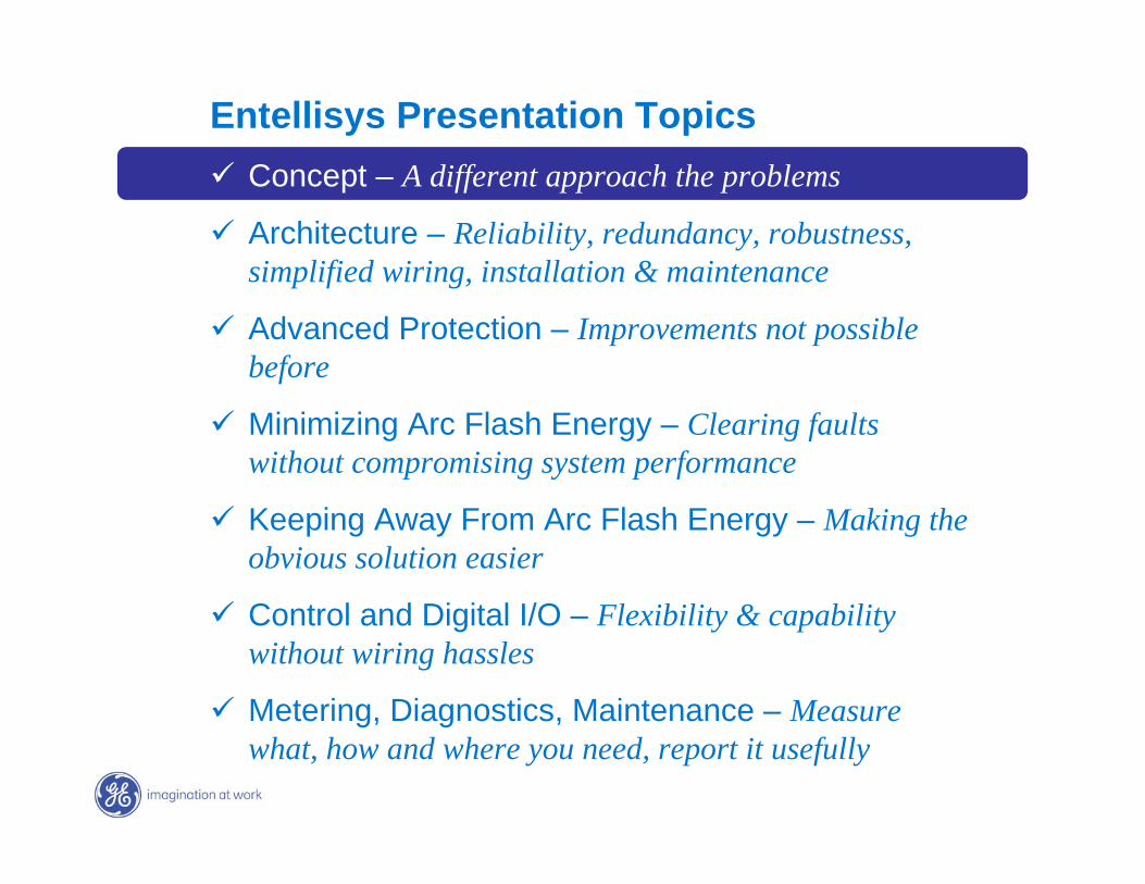
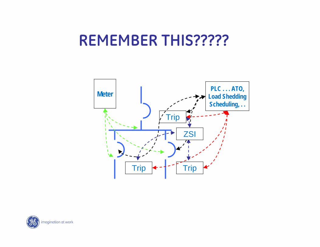
… Each evolution & enhancement = More Complexity
More complexity may mean less reliability
Multiple trips with different information …
all independent
Trip
Trip
Trip
MeterPLC . . . ATO,
Load Shedding Scheduling, . .
ZSI⌧⌧Let’s not add more of the same, Let’s change the way we do it completely
GE7 December 2004
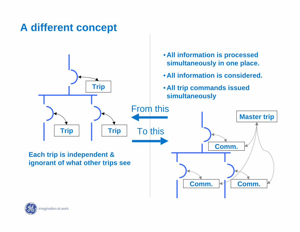
A different concept
Trip
Trip
Trip
Comm.
Comm.
Comm.
Master trip
Each trip is independent & ignorant of what other trips see
• All information is processed simultaneously in one place.
• All information is considered.
• All trip commands issued simultaneously
From this
To this
GE7 December 2004
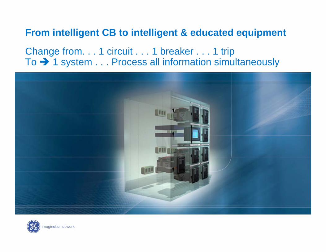
From intelligent CB to intelligent & educated equipment
Change from. . . 1 circuit . . . 1 breaker . . . 1 trip To 1 system . . . Process all information simultaneously
GE7 December 2004
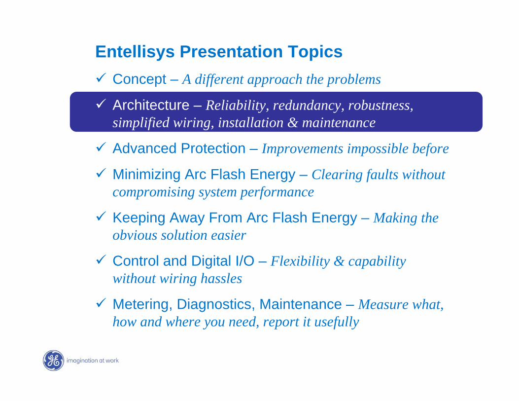
Entellisys Presentation Topics Concept – A different approach the problems
Architecture – Reliability, redundancy, robustness, simplified wiring, installation & maintenance
Advanced Protection – Improvements impossible before
Minimizing Arc Flash Energy – Clearing faults without compromising system performance
Keeping Away From Arc Flash Energy – Making the obvious solution easier
Control and Digital I/O – Flexibility & capability without wiring hassles
Metering, Diagnostics, Maintenance – Measure what, how and where you need, report it usefully
GE7 December 2004
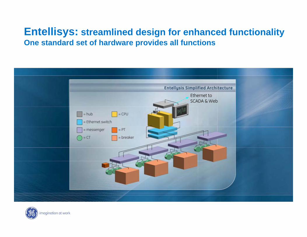
Entellisys: streamlined design for enhanced functionalityOne standard set of hardware provides all functions
Ethernet toEthernet toSCADA & WebSCADA & Web
GE7 December 2004
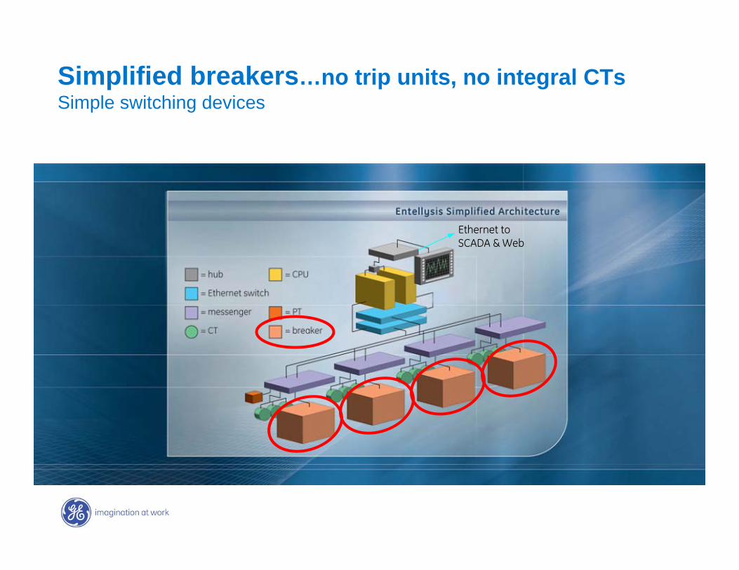
Simplified breakers…no trip units, no integral CTsSimple switching devices
Ethernet toEthernet toSCADA & WebSCADA & Web
GE7 December 2004
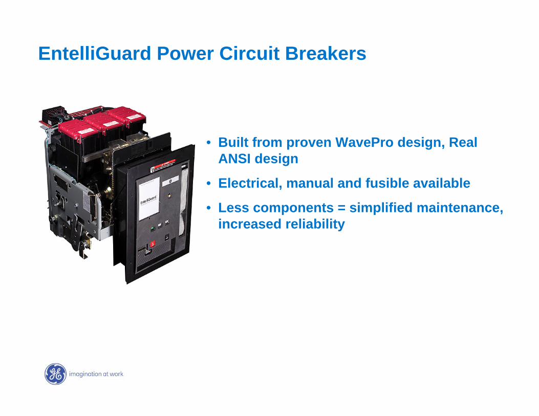
EntelliGuard Power Circuit Breakers
• Built from proven WavePro design, Real ANSI design
• Electrical, manual and fusible available
• Less components = simplified maintenance, increased reliability
GE7 December 2004
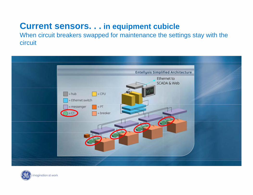
Current sensors. . . in equipment cubicleWhen circuit breakers swapped for maintenance the settings stay with the circuit
Ethernet toEthernet toSCADA & WebSCADA & Web
GE7 December 2004
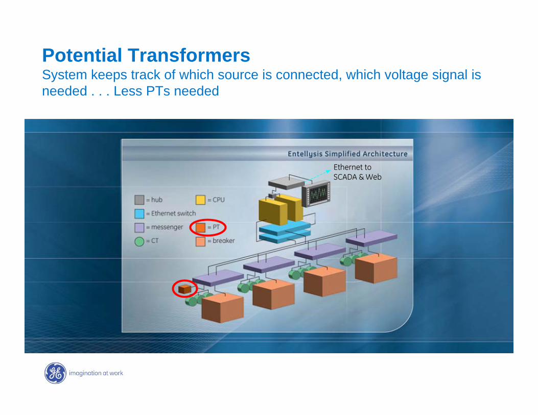
Potential Transformers System keeps track of which source is connected, which voltage signal is needed . . . Less PTs needed
Ethernet toEthernet toSCADA & WebSCADA & Web
GE7 December 2004
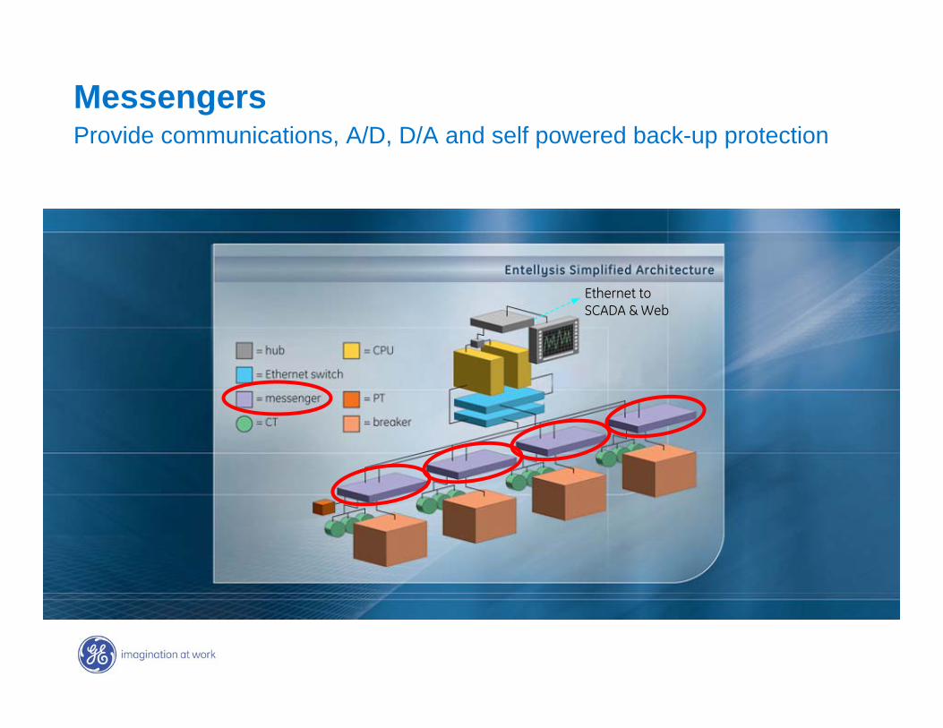
MessengersProvide communications, A/D, D/A and self powered back-up protection
Ethernet toEthernet toSCADA & WebSCADA & Web
GE7 December 2004
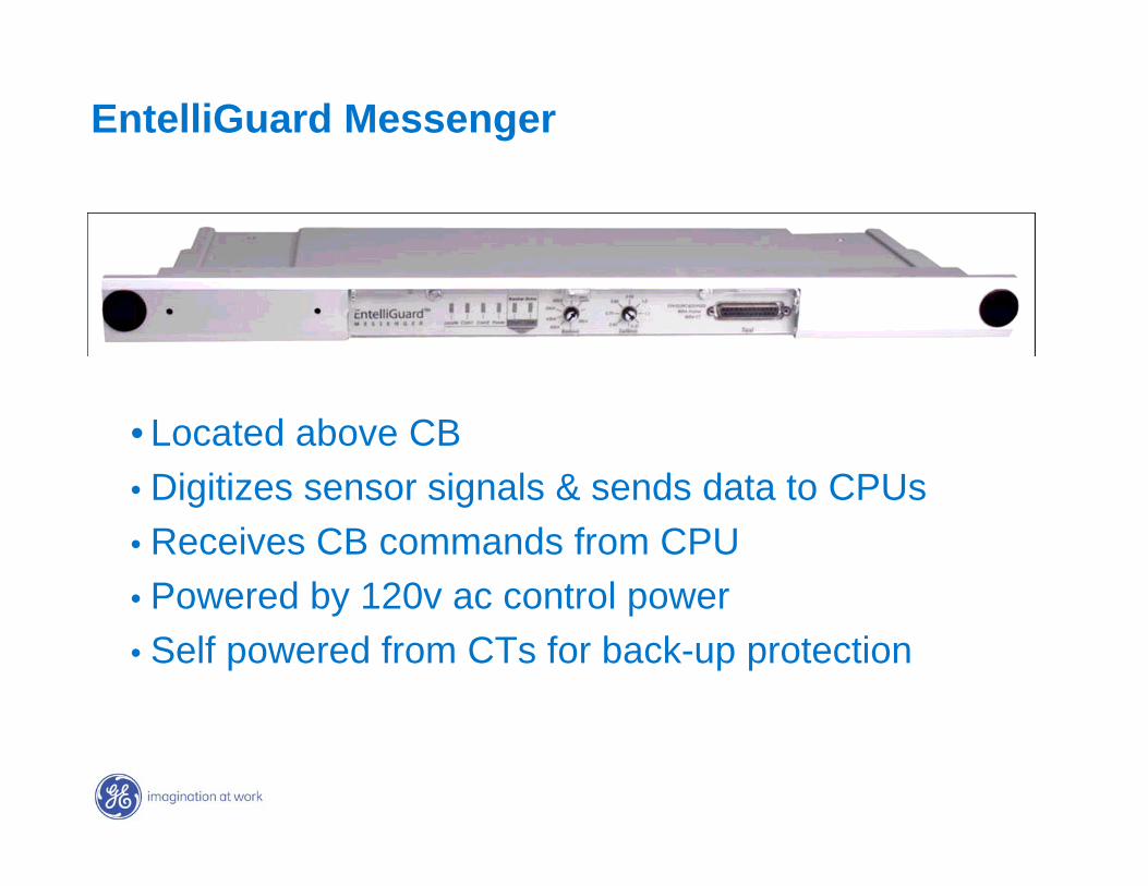
• Located above CB• Digitizes sensor signals & sends data to CPUs• Receives CB commands from CPU• Powered by 120v ac control power• Self powered from CTs for back-up protection
EntelliGuard Messenger
GE7 December 2004
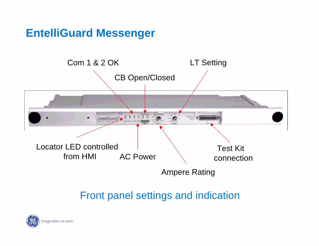
Locator LED controlled from HMI
Com 1 & 2 OK
AC Power
CB Open/Closed
Ampere Rating
LT Setting
Test Kit connection
EntelliGuard Messenger
Front panel settings and indication

GE7 December 2004
MessengersProvide communications, A/D, D/A and self powered back-up protection
Ethernet toEthernet toSCADA & WebSCADA & Web
GE7 December 2004
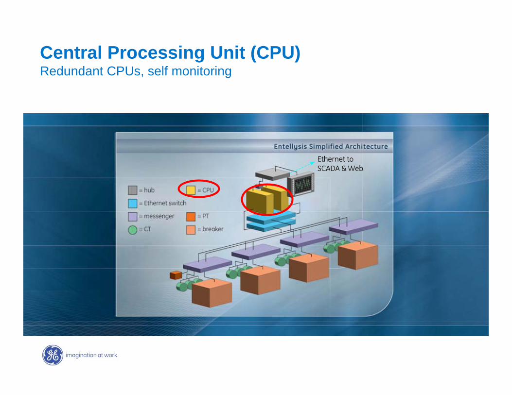
Central Processing Unit (CPU) Redundant CPUs, self monitoring
Ethernet toEthernet toSCADA & WebSCADA & Web

GE7 December 2004
Central Processing Units
Redundant industrial computers• Rack mounted• Real time operating system• Run simultaneously
GE7 December 2004
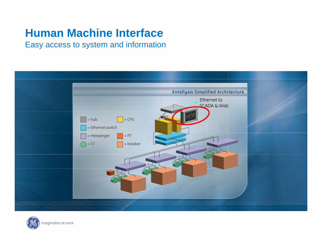
Human Machine InterfaceEasy access to system and information
Ethernet toEthernet toSCADA & WebSCADA & Web
GE7 December 2004
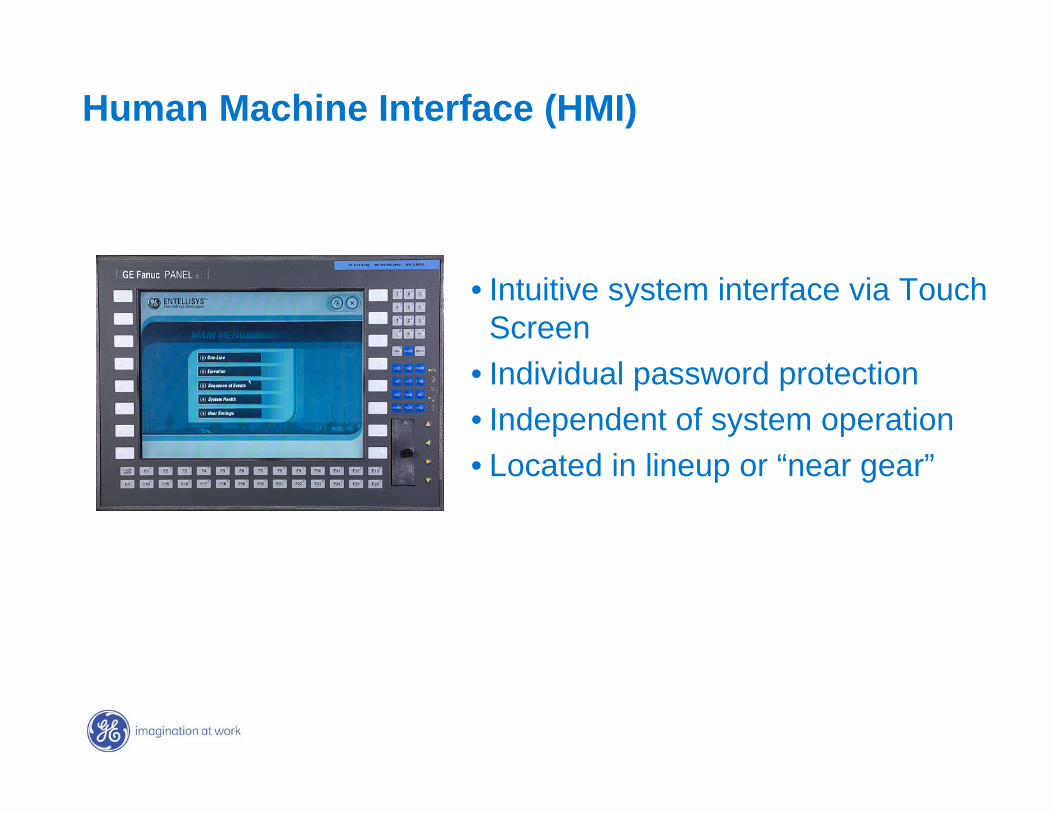
• Intuitive system interface via Touch Screen
• Individual password protection• Independent of system operation• Located in lineup or “near gear”
Human Machine Interface (HMI)
GE7 December 2004
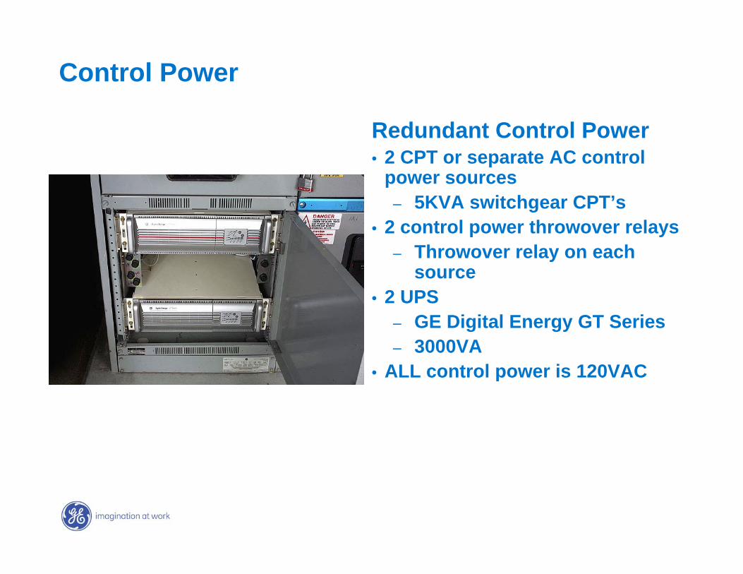
Control Power
Redundant Control Power• 2 CPT or separate AC control
power sources– 5KVA switchgear CPT’s
• 2 control power throwover relays– Throwover relay on each
source• 2 UPS
– GE Digital Energy GT Series– 3000VA
• ALL control power is 120VAC
GE7 December 2004
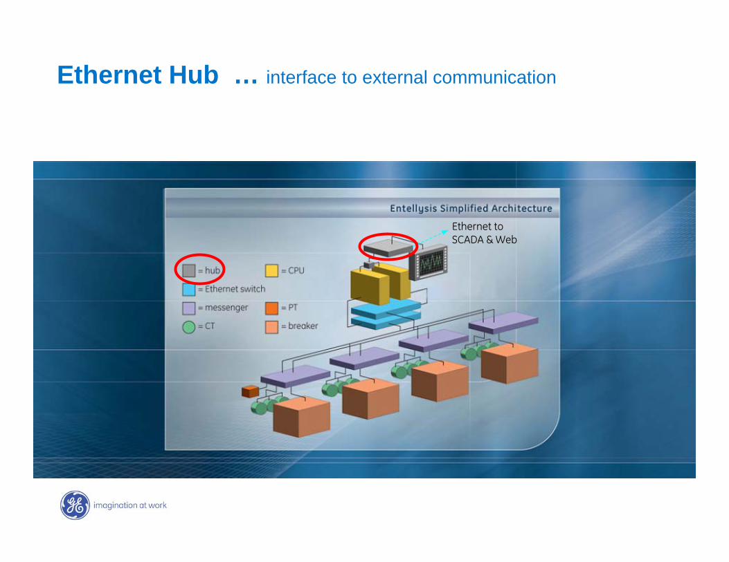
Ethernet Hub … interface to external communication
Ethernet toEthernet toSCADA & WebSCADA & Web
GE7 December 2004
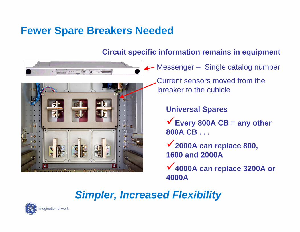
Fewer Spare Breakers Needed
Circuit specific information remains in equipment
Simpler, Increased Flexibility
Universal Spares
Every 800A CB = any other 800A CB . . .
2000A can replace 800, 1600 and 2000A
4000A can replace 3200A or 4000A
Messenger – Single catalog number
Current sensors moved from the breaker to the cubicle
GE7 December 2004
Trip
Trip
Trip
MeterPLC . . . ATO,
Load Shedding Scheduling, . .
ZSI
REMEMBER THIS?????
GE7 December 2004
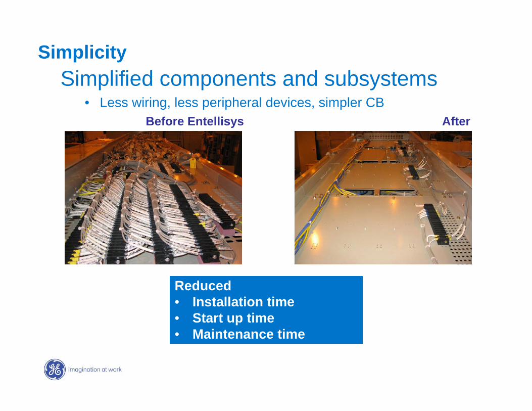
SimplicitySimplified components and subsystems
• Less wiring, less peripheral devices, simpler CBBefore Entellisys After
Reduced • Installation time• Start up time• Maintenance time
GE7 December 2004
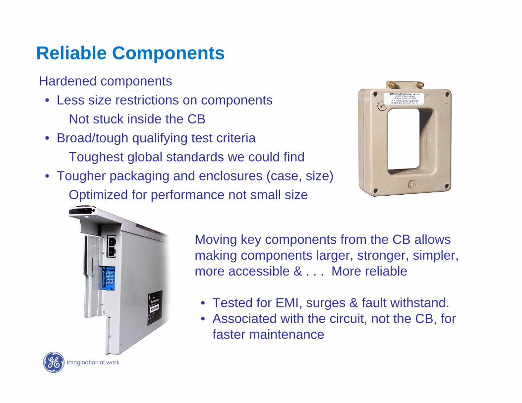
Hardened components• Less size restrictions on components
Not stuck inside the CB• Broad/tough qualifying test criteria
Toughest global standards we could find• Tougher packaging and enclosures (case, size)
Optimized for performance not small size
Reliable Components
Moving key components from the CB allows making components larger, stronger, simpler, more accessible & . . . More reliable
• Tested for EMI, surges & fault withstand. • Associated with the circuit, not the CB, for
faster maintenance
GE7 December 2004
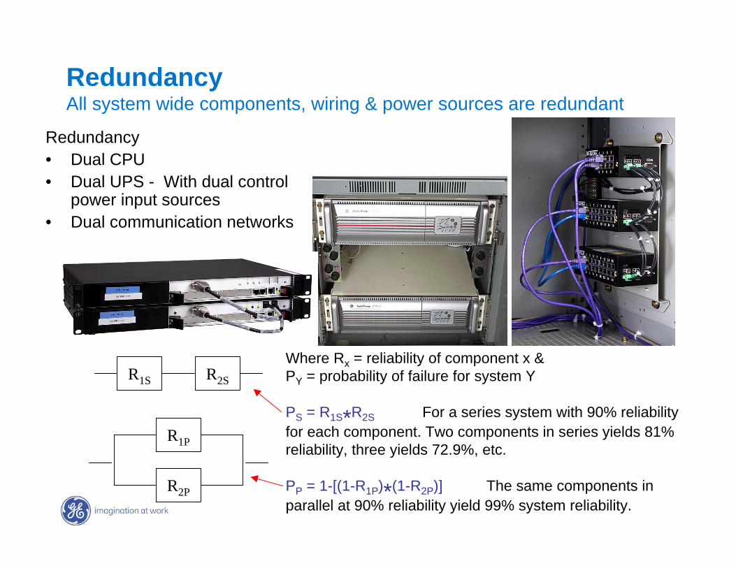
RedundancyAll system wide components, wiring & power sources are redundant
Redundancy• Dual CPU• Dual UPS - With dual control
power input sources• Dual communication networks
R1S R2S
R1P
R2P
Where Rx = reliability of component x &PY = probability of failure for system Y
PS = R1S*R2S For a series system with 90% reliability for each component. Two components in series yields 81% reliability, three yields 72.9%, etc.
PP = 1-[(1-R1P)*(1-R2P)] The same components in parallel at 90% reliability yield 99% system reliability.
GE7 December 2004
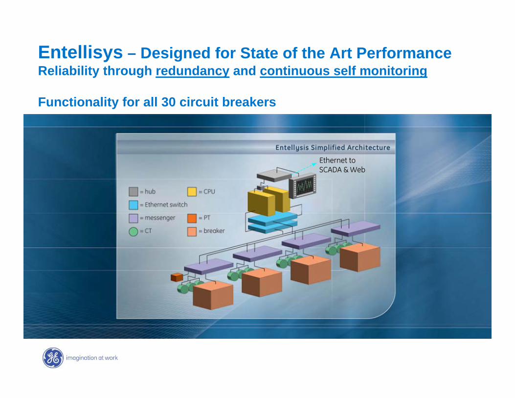
Entellisys – Designed for State of the Art PerformanceReliability through redundancy and continuous self monitoring
Functionality for all 30 circuit breakers
Ethernet toEthernet toSCADA & WebSCADA & Web
GE7 December 2004
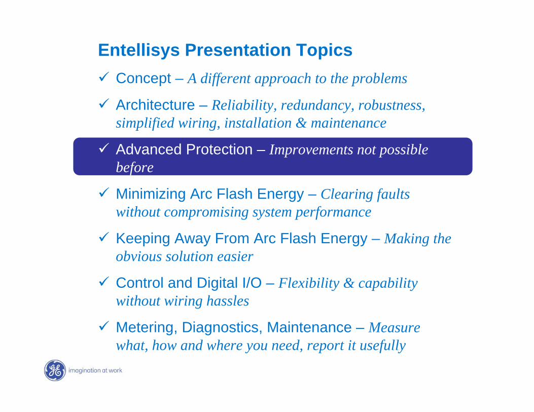
Entellisys Presentation Topics Concept – A different approach to the problems
Architecture – Reliability, redundancy, robustness, simplified wiring, installation & maintenance
Advanced Protection – Improvements not possible before
Minimizing Arc Flash Energy – Clearing faults without compromising system performance
Keeping Away From Arc Flash Energy – Making the obvious solution easier
Control and Digital I/O – Flexibility & capability without wiring hassles
Metering, Diagnostics, Maintenance – Measure what, how and where you need, report it usefully
GE7 December 2004
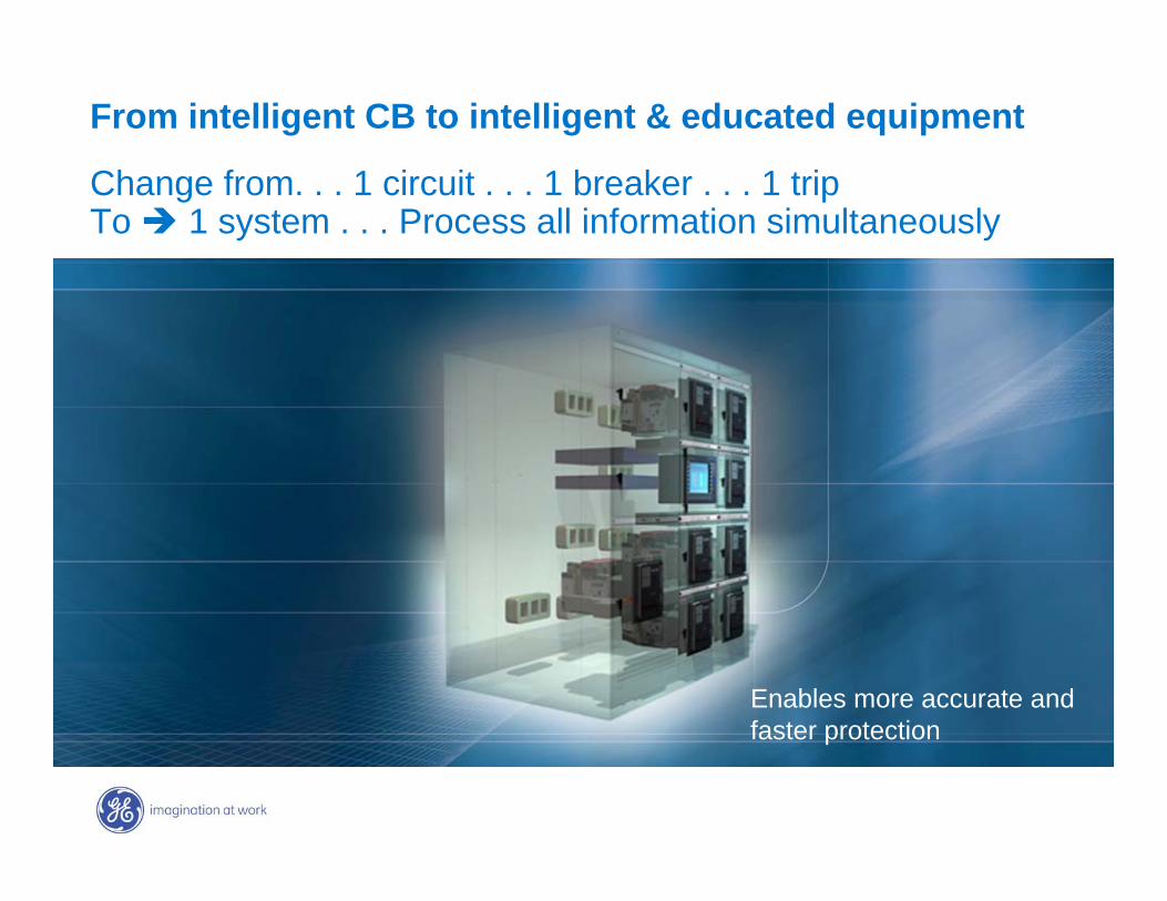
From intelligent CB to intelligent & educated equipment
Change from. . . 1 circuit . . . 1 breaker . . . 1 trip To 1 system . . . Process all information simultaneously
Enables more accurate and faster protection
GE7 December 2004
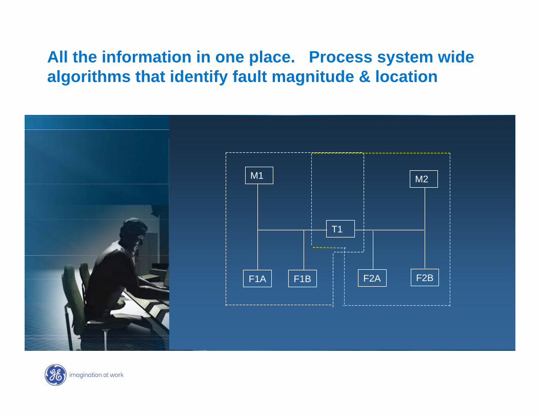
All the information in one place. Process system wide algorithms that identify fault magnitude & location
M1 M2
T1
F1A F1B F2A F2B
GE7 December 2004
Switchgear Yesterday (Traditional Switchgear)
• Selectivity depends on time delays and lowered sensitivity
• Back up and primary protection is the same for mains and ties
• Clearing speed depends on fault magnitude and fault location . . .
Therefore -- arc flash risk, equipment damage varies
GE7 December 2004
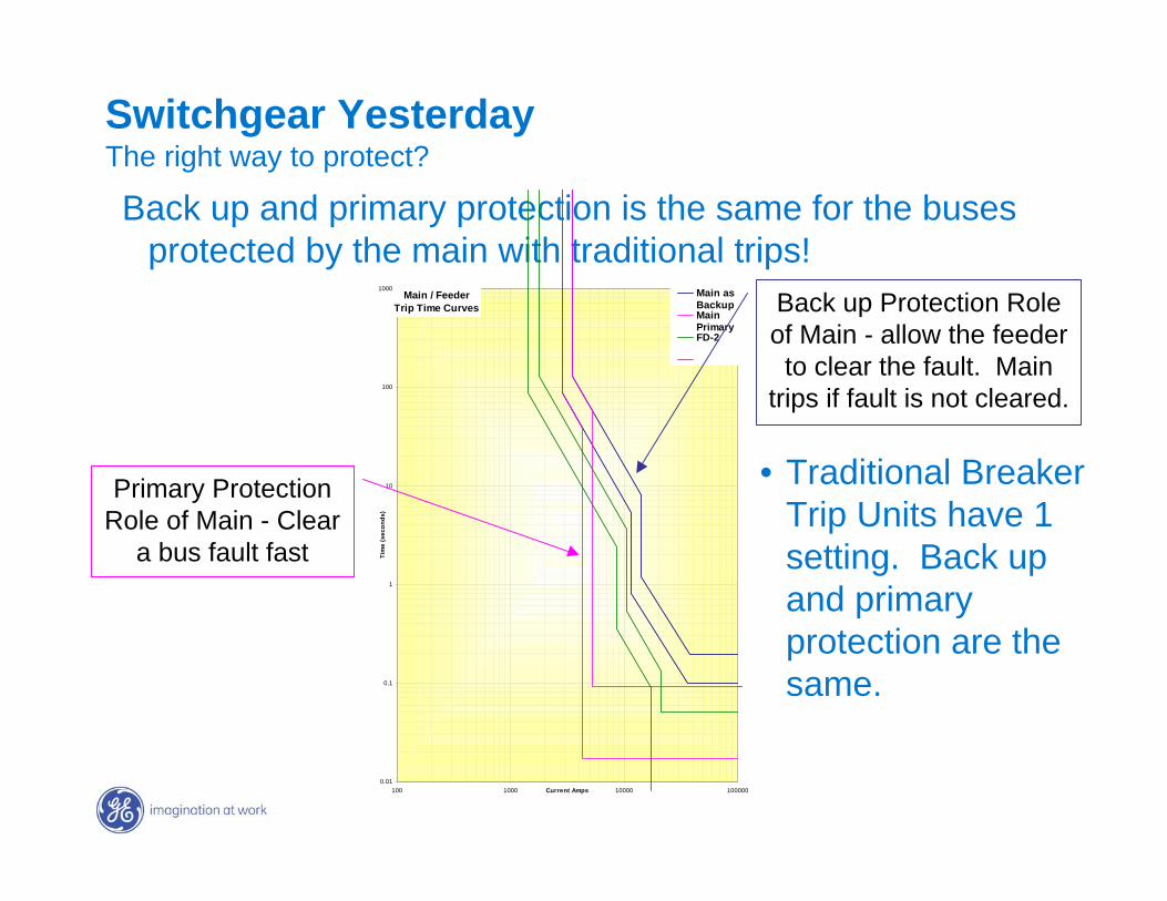
Switchgear Yesterday The right way to protect?
Back up and primary protection is the same for the buses protected by the main with traditional trips!
Main / FeederTrip Time Curves
0.01
0.1
1
10
100
1000
100 1000 10000 100000Current Amps
Tim
e (s
econ
ds)
Main asBackupMainPrimaryFD-2
Primary Protection Role of Main - Clear
a bus fault fast
Back up Protection Role of Main - allow the feeder
to clear the fault. Main trips if fault is not cleared.
• Traditional Breaker Trip Units have 1 setting. Back up and primary protection are the same.
GE7 December 2004
Zone based protectionThe right way to protect
Entellisys today• Selective protection depends on fault location, not fault
magnitude
• Nested delays are unnecessary
• Primary protection is always fast
• Back up protection minimally slowed
• Arc flash risk & equipment damage minimized regardless fault magnitude or location
• Improved Energy reduction for branch circuits
GE7 December 2004
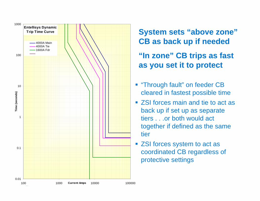
Entellisys DynamicTrip Time Curve
0.01
0.1
1
10
100
1000
100 1000 10000 100000Current Amps
Tim
e (s
econ
ds)
4000A Main4000A Tie1600A Fdr
“Through fault” on feeder CB cleared in fastest possible timeZSI forces main and tie to act as back up if set up as separate tiers . . .or both would act together if defined as the same tierZSI forces system to act as coordinated CB regardless of protective settings
System sets “above zone” CB as back up if needed
“In zone” CB trips as fast as you set it to protect
GE7 December 2004
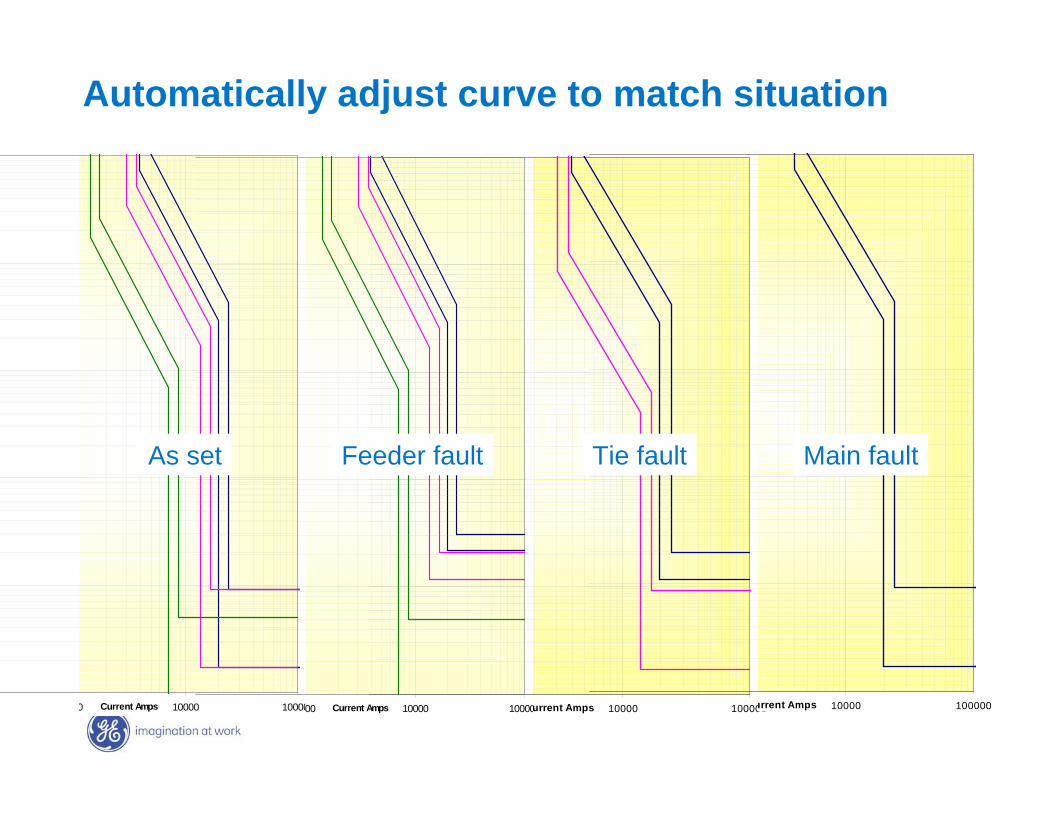
0 10000 100000Current Amps 00 10000 100000Current Amps 10000 100000urrent Amps 10000 100000urrent Amps
Automatically adjust curve to match situation
As set Feeder fault Tie fault Main fault
GE7 December 2004
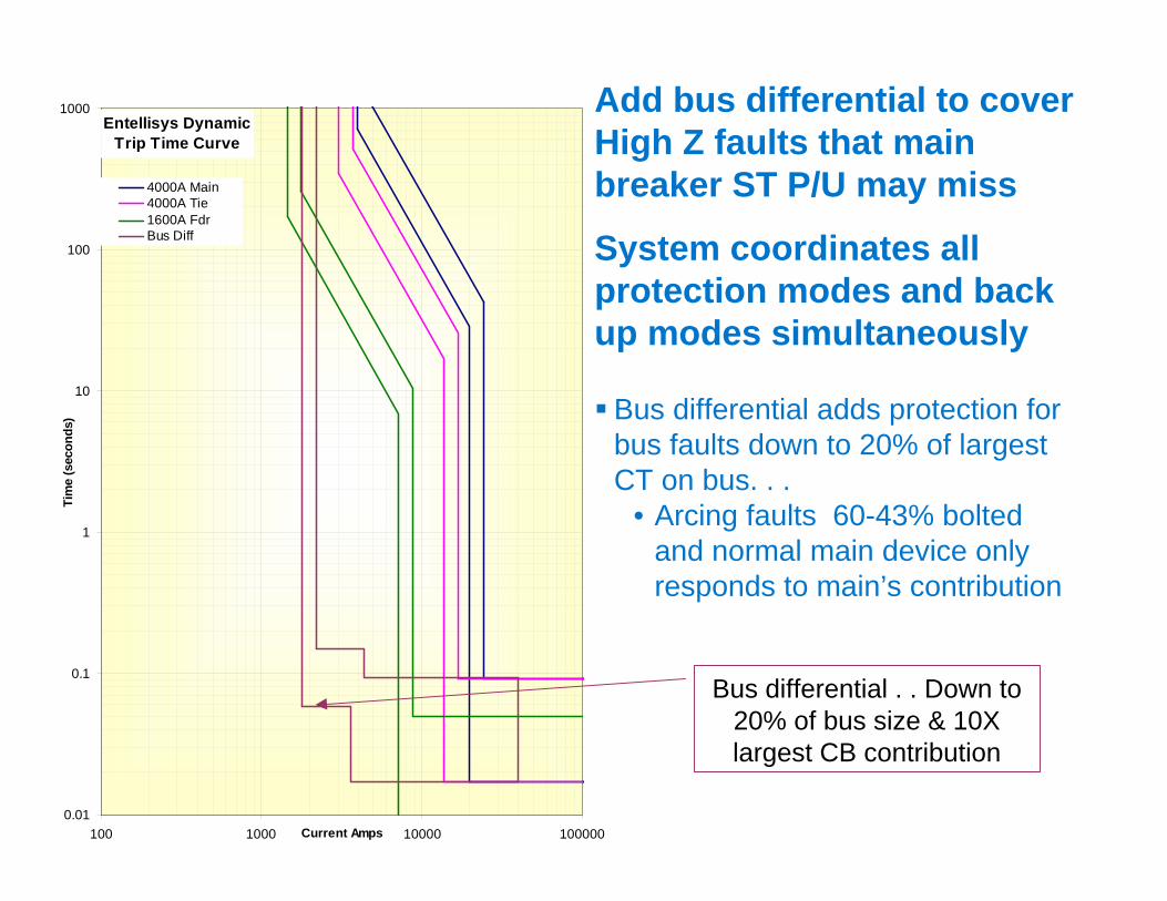
Entellisys DynamicTrip Time Curve
0.01
0.1
1
10
100
1000
100 1000 10000 100000Current Amps
Tim
e (s
econ
ds)
4000A Main4000A Tie1600A FdrBus Diff
Bus differential adds protection for bus faults down to 20% of largest CT on bus. . .
• Arcing faults 60-43% bolted and normal main device only responds to main’s contribution
Bus differential . . Down to 20% of bus size & 10X largest CB contribution
Add bus differential to cover High Z faults that main breaker ST P/U may miss
System coordinates all protection modes and back up modes simultaneously
GE7 December 2004
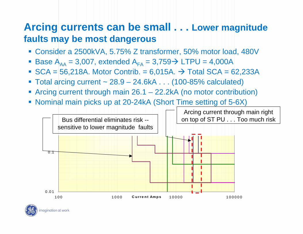
Consider a 2500kVA, 5.75% Z transformer, 50% motor load, 480VBase AAA = 3,007, extended AFA = 3,759 LTPU = 4,000ASCA = 56,218A. Motor Contrib. = 6,015A. Total SCA = 62,233ATotal arcing current ~ 28.9 – 24.6kA . . . (100-85% calculated)Arcing current through main 26.1 – 22.2kA (no motor contribution)Nominal main picks up at 20-24kA (Short Time setting of 5-6X)
0 .0 1
0 .1
1 0 0 1 0 0 0 1 0 0 0 0 1 0 0 0 0 0C u rre n t Am p s
Arcing current through main right on top of ST PU . . . Too much riskBus differential eliminates risk --
sensitive to lower magnitude faults
Arcing currents can be small . . . Lower magnitude faults may be most dangerous
GE7 December 2004
Entellisys Presentation Topics Concept – A different approach to the problems
Architecture – Reliability, redundancy, robustness, simplified wiring, installation & maintenance
Advanced Protection – Improvements not possible before
Minimizing Arc Flash Energy – Clearing faults without compromising system performance
Keeping Away From Arc Flash Energy – Making the obvious solution easier
Control and Digital I/O – Flexibility & capability without wiring hassles
Metering, Diagnostics, Maintenance – Measure what, how and where you need, report it usefully
GE7 December 2004
How is arc flash hazard determined
Perform a study and determine values
• Spreadsheet approach can be used for small systems
• Arc Flash calculation modules can be obtained with commercially available comprehensive power system modeling software.
1. Short-Circuit Study
2. Protective Device Coordination Analysis
3. Arc Flash analysis
GE7 December 2004
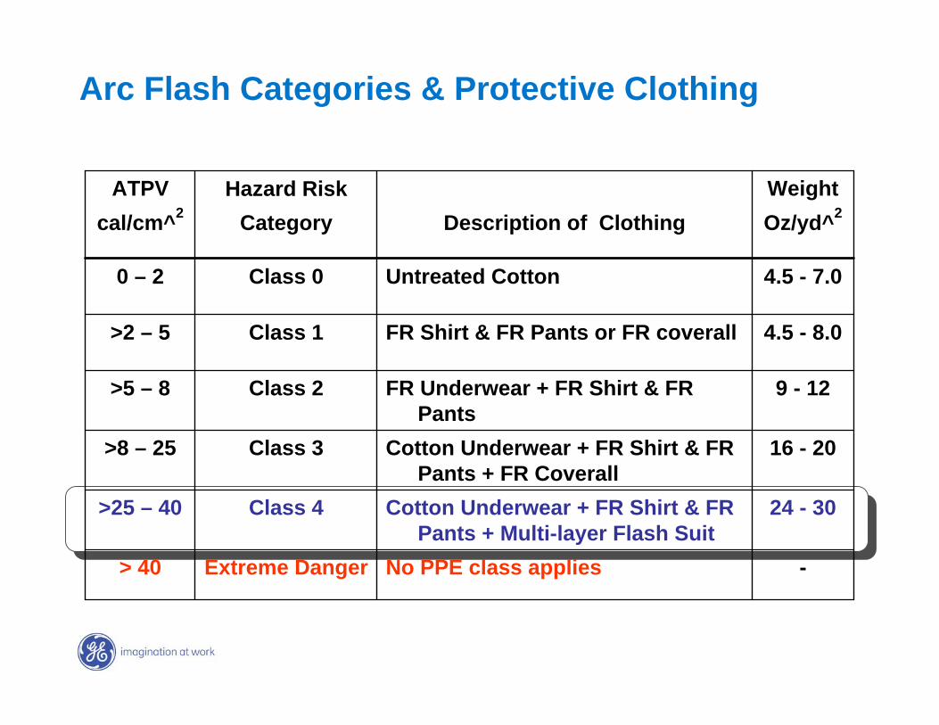
Arc Flash Categories & Protective Clothing
-No PPE class appliesExtreme Danger> 40
24 - 30Cotton Underwear + FR Shirt & FR Pants + Multi-layer Flash Suit
Class 4>25 – 40
16 - 20Cotton Underwear + FR Shirt & FR Pants + FR Coverall
Class 3>8 – 25
9 - 12FR Underwear + FR Shirt & FR Pants
Class 2>5 – 8
4.5 - 8.0FR Shirt & FR Pants or FR coverallClass 1>2 – 5
4.5 - 7.0Untreated CottonClass 00 – 2
Oz/yd^2Description of ClothingCategorycal/cm^2Weight Hazard RiskATPV
GE7 December 2004
So how is Entellisys different
SinceArc Flash energy is a function of:• Voltage – Fixed for the systems• Available short circuit current – Fixed by system design and source• Working distance – Arms are only so long• Arc gap – determined by equipment type• Arcing fault clearing time (not short circuit clearing time) A function of
the protective device acting upon arcing current
Short Circuit current is fixed, can’t change voltage, arms or the hot stick are only so long . . . Clearing time is the only parameter than can be modified. So . . .
Arcing fault clearing time becomes the critical factor
GE7 December 2004
500 1K 10K 100K0.01
0.10
1
10
100
1000
TM 4000A
TF 1600A
TM 4000A
TF 1600A
0
5
10
15
20
25
30
35
40
45
50
0 10 20 30 40 50 60 70 80
Bolted Fault Current Available
Cal
orie
s/C
M2
@ 1
8"1600A Traditional FdrHRC LEVELS4000A main
HRC4
HRC3
HRC2
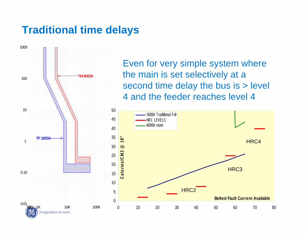
Even for very simple system where the main is set selectively at a second time delay the bus is > level 4 and the feeder reaches level 4
Traditional time delays
GE7 December 2004
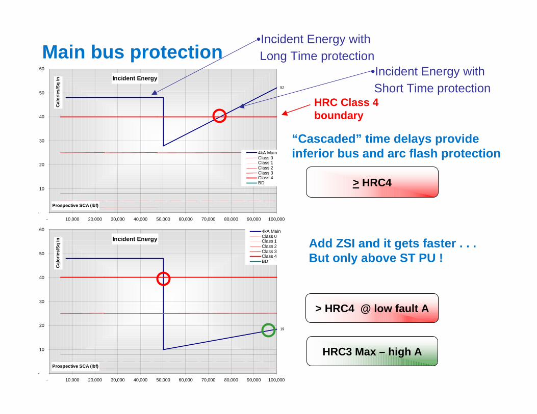
Main bus protection
Add ZSI and it gets faster . . . But only above ST PU !
> HRC4
HRC3 Max – high A
> HRC4 @ low fault A
“Cascaded” time delays provide inferior bus and arc flash protection
Incident Energy52
-
10
20
30
40
50
60
- 10,000 20,000 30,000 40,000 50,000 60,000 70,000 80,000 90,000 100,000
Prospective SCA (Ibf)
Cal
orie
s/Sq
in
4kA MainClass 0Class 1Class 2Class 3Class 4BD
Incident Energy
19
-
10
20
30
40
50
60
- 10,000 20,000 30,000 40,000 50,000 60,000 70,000 80,000 90,000 100,000
Prospective SCA (Ibf)
Cal
orie
s/Sq
in
4kA MainClass 0Class 1Class 2Class 3Class 4BD
HRC Class 4 boundary
•Incident Energy withShort Time protection
•Incident Energy withLong Time protection
GE7 December 2004
Entellisys DynamicTrip Time Curve
0.01
0.1
1
10
100
1000
100 1000 10000 100000Current Amps
Tim
e (s
econ
ds)
4000A Main4000A Tie1600A FdrBus Diff
Incident Energy
19
-
10
20
30
40
50
60
- 10,000 20,000 30,000 40,000 50,000 60,000 70,000 80,000 90,000 100,000
Prospective SCA (Ibf)
Cal
orie
s/Sq
in
4kA MainClass 0Class 1Class 2Class 3Class 4BD
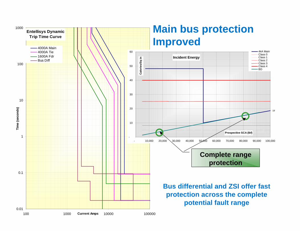
Complete range protection
Main bus protection Improved
Bus differential and ZSI offer fast protection across the complete
potential fault range
GE7 December 2004
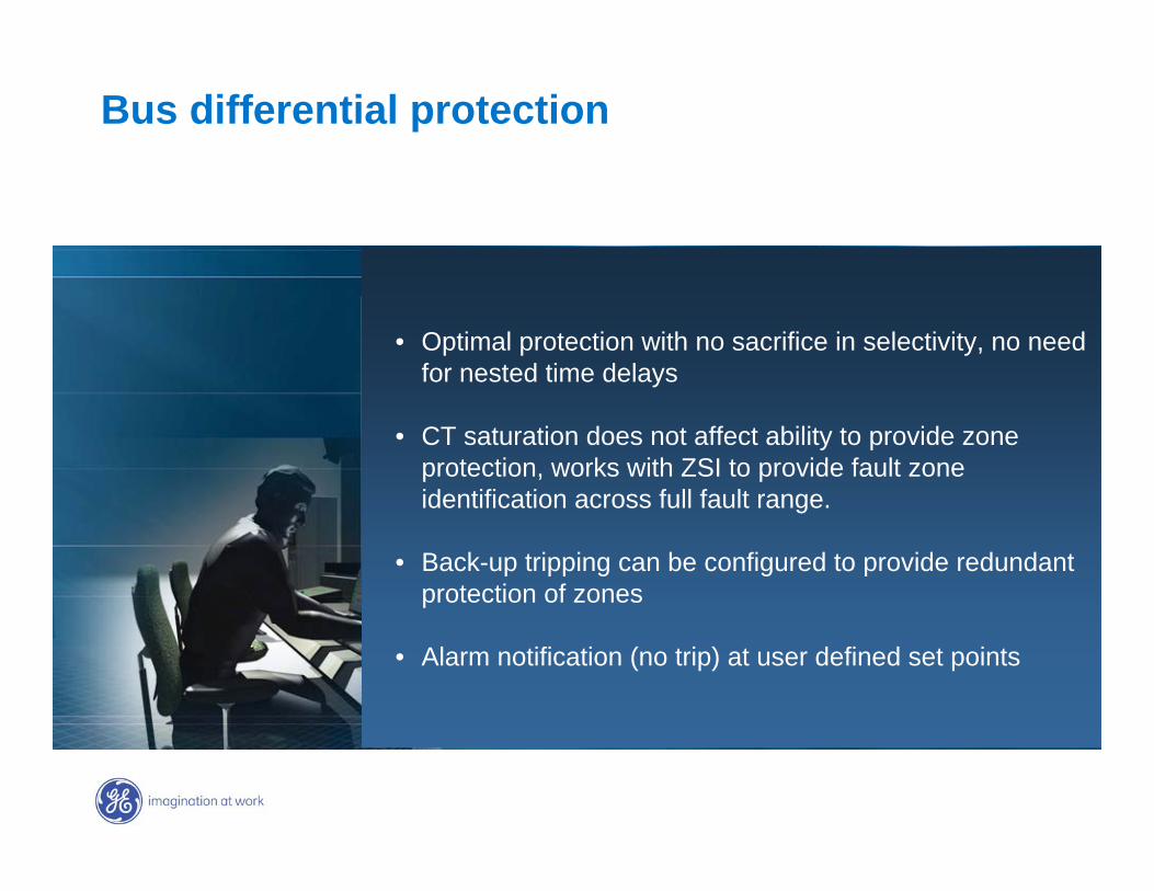
Bus differential protection
• Optimal protection with no sacrifice in selectivity, no need for nested time delays
• CT saturation does not affect ability to provide zone protection, works with ZSI to provide fault zone identification across full fault range.
• Back-up tripping can be configured to provide redundant protection of zones
• Alarm notification (no trip) at user defined set points
GE7 December 2004
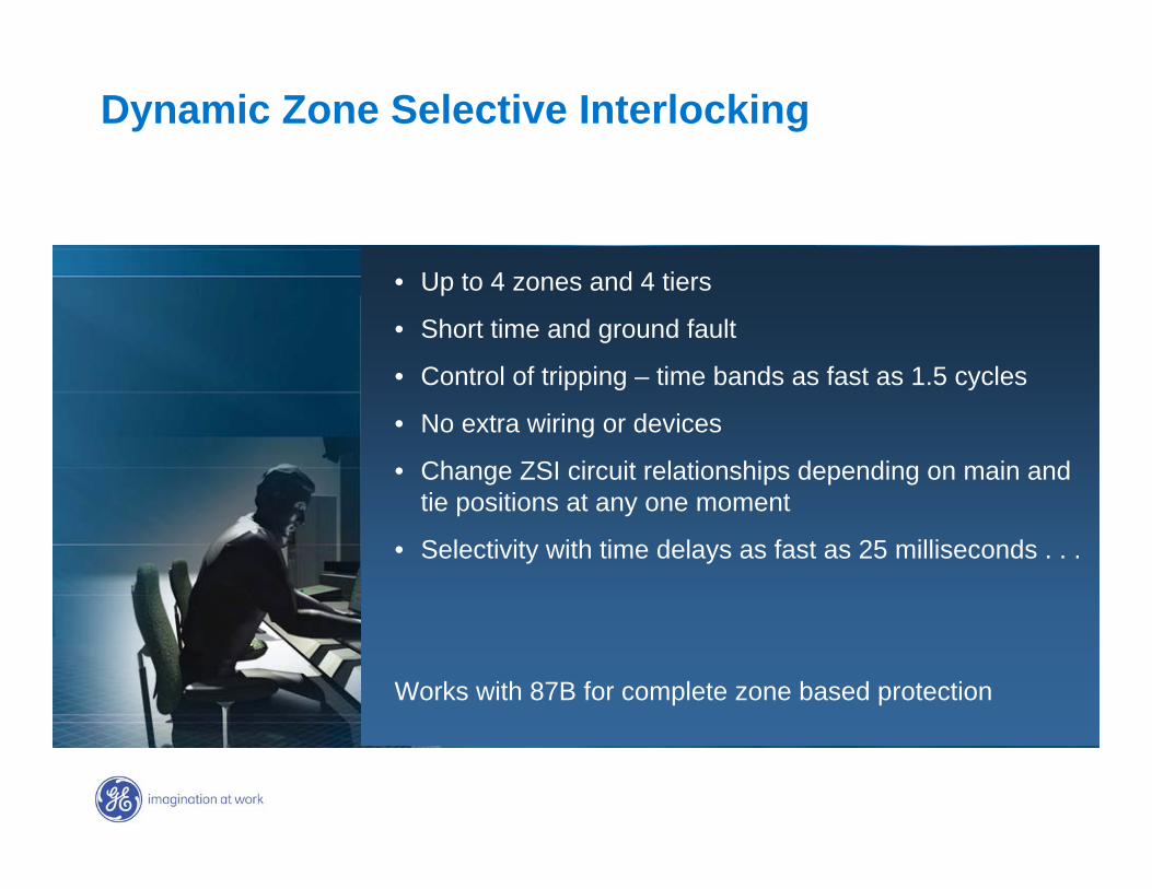
Dynamic Zone Selective Interlocking
• Up to 4 zones and 4 tiers
• Short time and ground fault
• Control of tripping – time bands as fast as 1.5 cycles
• No extra wiring or devices
• Change ZSI circuit relationships depending on main and tie positions at any one moment
• Selectivity with time delays as fast as 25 milliseconds . . .
Works with 87B for complete zone based protection
GE7 December 2004
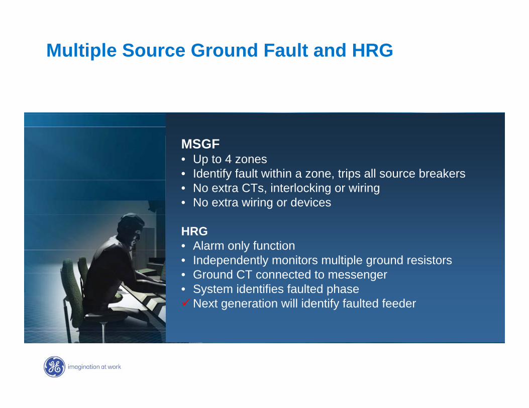
Multiple Source Ground Fault and HRG
MSGF • Up to 4 zones • Identify fault within a zone, trips all source breakers• No extra CTs, interlocking or wiring• No extra wiring or devices
HRG• Alarm only function• Independently monitors multiple ground resistors• Ground CT connected to messenger• System identifies faulted phase
Next generation will identify faulted feeder
GE7 December 2004
Entellisys Presentation Topics Concept – A different approach the problems
Architecture – Reliability, redundancy, robustness, simplified wiring, installation & maintenance
Advanced Protection – Improvements not possible before
Minimizing Arc Flash Energy – Clearing faults without compromising system performance
Keeping Away From Arc Flash Energy – Making the obvious solution easier
Control and Digital I/O – Flexibility & capability without wiring hassles
Metering, Diagnostics, Maintenance – Measure what, how and where you need, report it usefully
GE7 December 2004
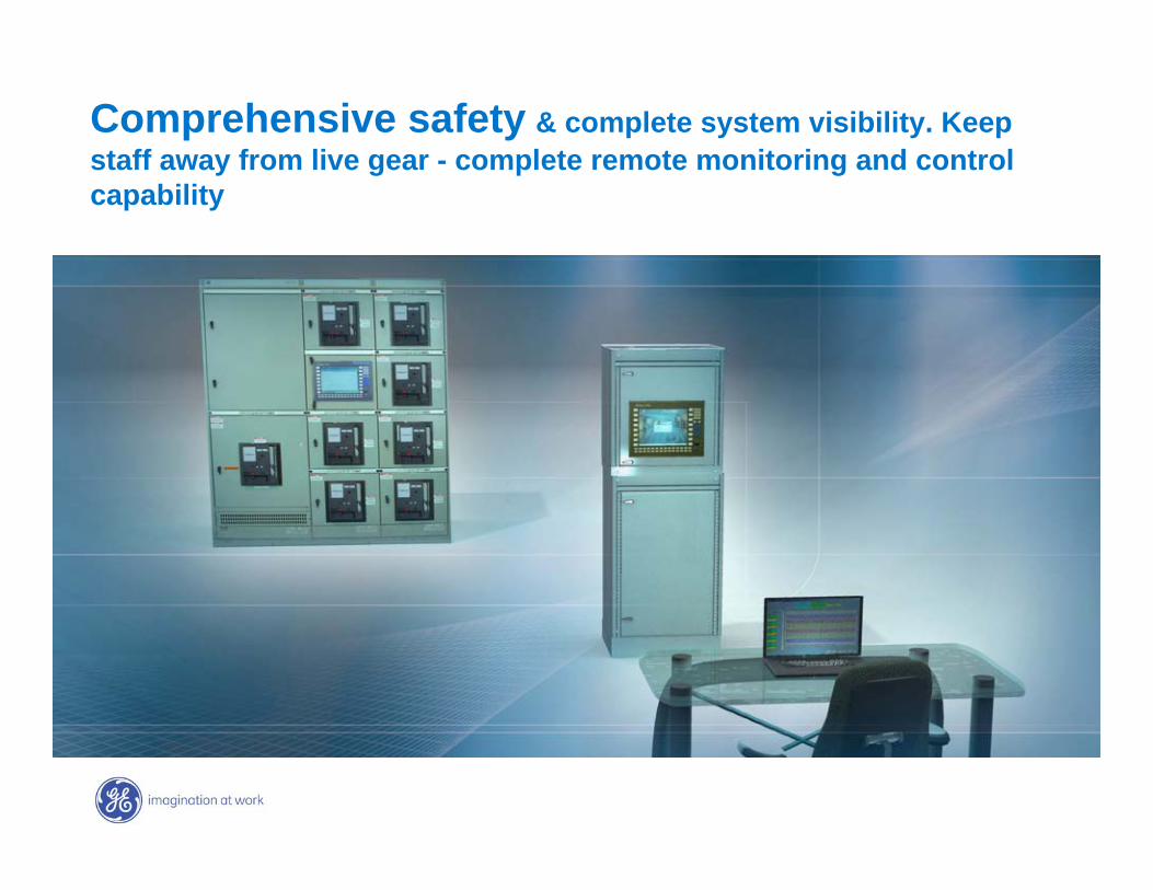
Comprehensive safety & complete system visibility. Keep staff away from live gear - complete remote monitoring and control capability
GE7 December 2004
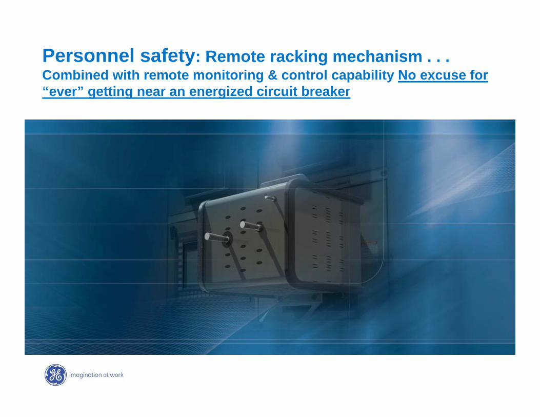
Personnel safety: Remote racking mechanism . . . Combined with remote monitoring & control capability No excuse for “ever” getting near an energized circuit breaker
GE7 December 2004
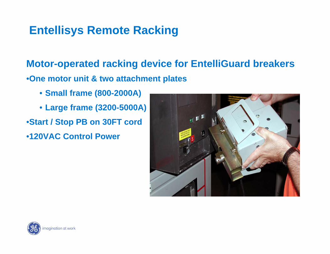
Entellisys Remote Racking
Motor-operated racking device for EntelliGuard breakers•One motor unit & two attachment plates
• Small frame (800-2000A)
• Large frame (3200-5000A)
•Start / Stop PB on 30FT cord
•120VAC Control Power
GE7 December 2004
Entellisys Presentation Topics Concept – A different approach the problems
Architecture – Reliability, redundancy, robustness, simplified wiring, installation & maintenance
Advanced Protection – Improvements not possible before
Minimizing Arc Flash Energy – Clearing faults without compromising system performance
Keeping Away From Arc Flash Energy – Making the obvious solution easier
Control and Digital I/O – Flexibility & capability without wiring hassles
Metering, Diagnostics, Maintenance – Measure what, how and where you need, report it usefully
GE7 December 2004
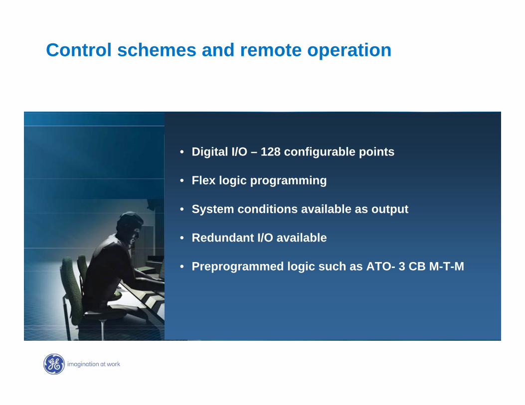
Control schemes and remote operation
• Digital I/O – 128 configurable points
• Flex logic programming
• System conditions available as output
• Redundant I/O available
• Preprogrammed logic such as ATO- 3 CB M-T-M
GE7 December 2004
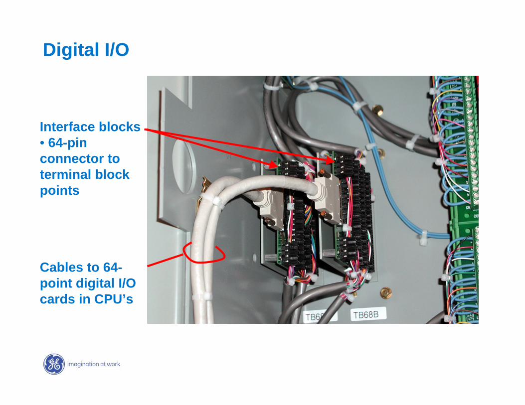
Digital I/O
Interface blocks• 64-pin connector to terminal block points
Cables to 64-point digital I/O cards in CPU’s
GE7 December 2004
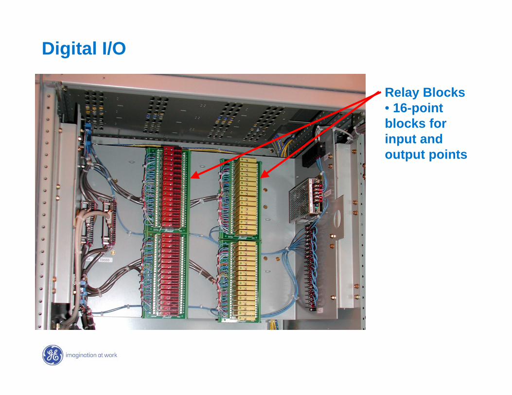
Relay Blocks• 16-point blocks for input and output points
Digital I/O
GE7 December 2004
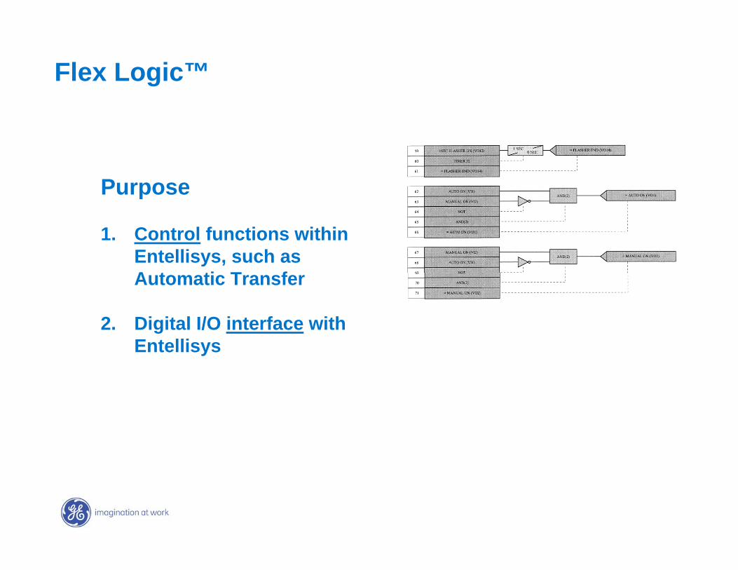
Flex Logic™
Purpose
1. Control functions within Entellisys, such as Automatic Transfer
2. Digital I/O interface with Entellisys
GE7 December 2004
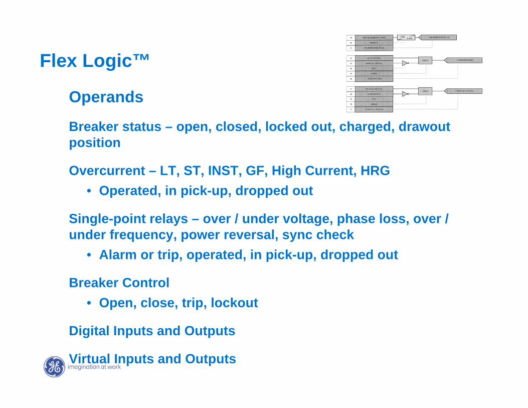
Flex Logic™
Operands
Breaker status – open, closed, locked out, charged, drawout position
Overcurrent – LT, ST, INST, GF, High Current, HRG• Operated, in pick-up, dropped out
Single-point relays – over / under voltage, phase loss, over / under frequency, power reversal, sync check
• Alarm or trip, operated, in pick-up, dropped out
Breaker Control• Open, close, trip, lockout
Digital Inputs and Outputs
Virtual Inputs and Outputs
GE7 December 2004
Structured Auto Transfer Scheme for Main-Tie-Main • Uses Entellisys internal protective relay functions and Flex Logic
programming• Under/overvoltage, under/overfrequency, phase loss, sync check
on each main breaker• Manual or Auto Return to Normal• Open Transition (Break-before-Make) or Closed Transition (Make-
before-Break) on Return to Normal
Automatic Transfer
GE7 December 2004
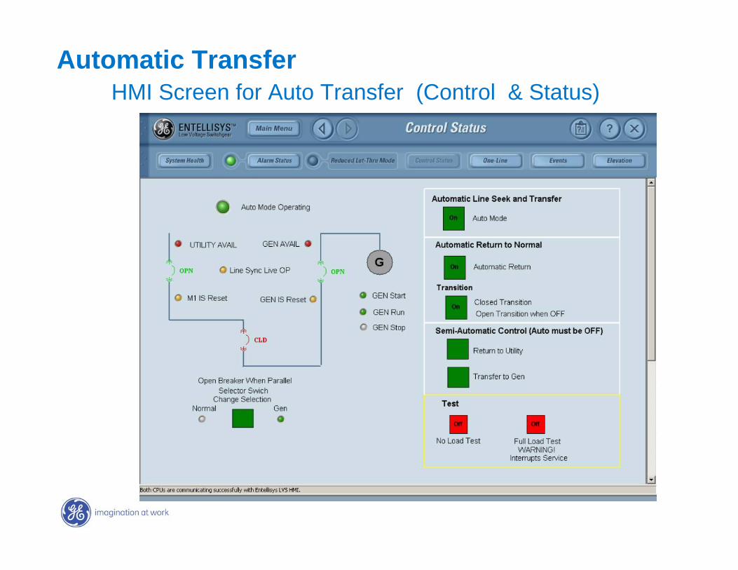
HMI Screen for Auto Transfer (Control & Status)Automatic Transfer
GE7 December 2004
Entellisys Presentation Topics Concept – A different approach the problems
Architecture – Reliability, redundancy, robustness, simplified wiring, installation & maintenance
Advanced Protection – Improvements not possible before
Minimizing Arc Flash Energy – Clearing faults without compromising system performance
Keeping Away From Arc Flash Energy – Making the obvious solution easier
Control and Digital I/O – Flexibility & capability without wiring hassles
Metering, Diagnostics, Maintenance – Measure what, how and where you need, report it usefully
GE7 December 2004
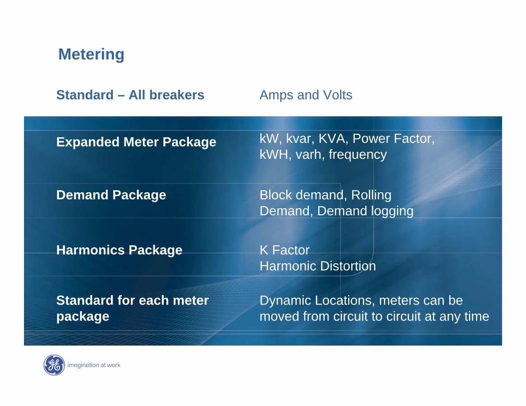
kW, kvar, KVA, Power Factor,kWH, varh, frequency
Expanded Meter Package
Block demand, Rolling Demand, Demand logging
Demand Package
K FactorHarmonic Distortion
Harmonics Package
Amps and VoltsStandard – All breakers
Metering
Dynamic Locations, meters can be moved from circuit to circuit at any time
Standard for each meter package
GE7 December 2004
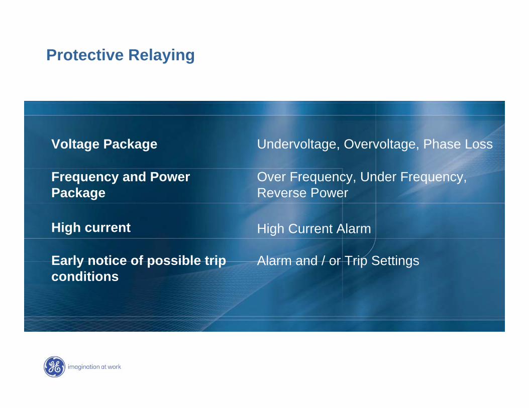
Protective Relaying
Undervoltage, Overvoltage, Phase LossVoltage Package
Frequency and PowerPackage
Over Frequency, Under Frequency, Reverse Power
High current High Current Alarm
Alarm and / or Trip SettingsEarly notice of possible trip conditions
GE7 December 2004
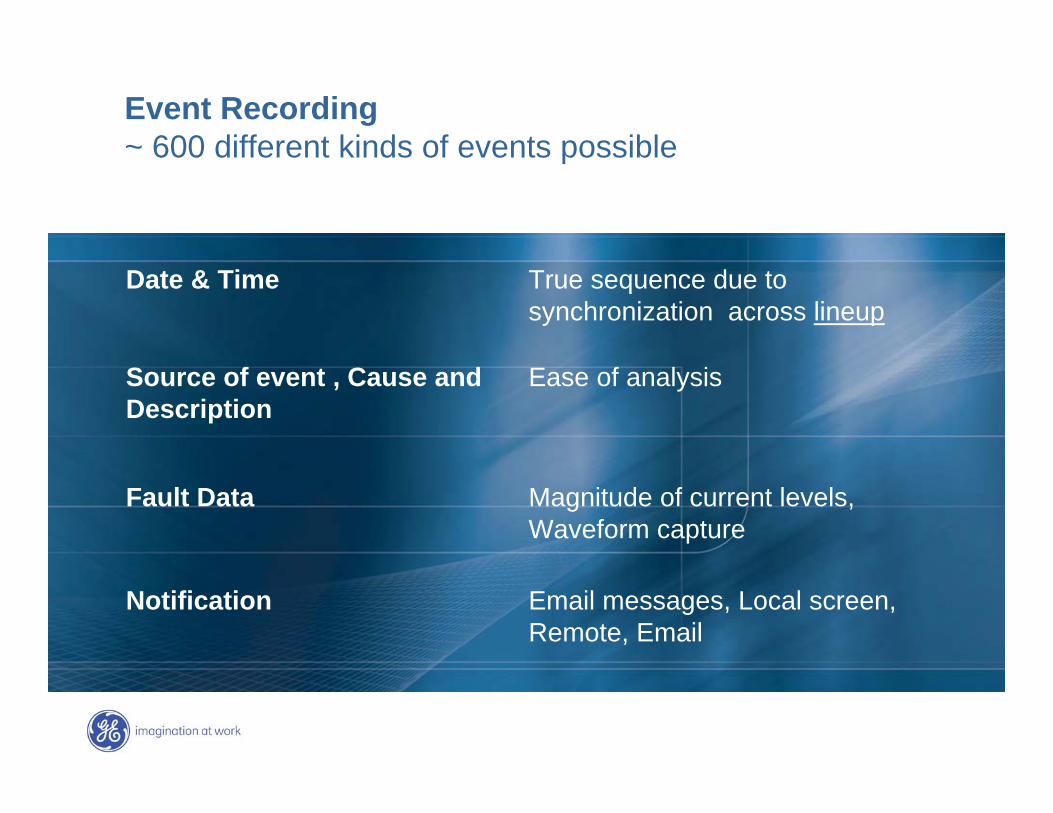
Event Recording~ 600 different kinds of events possible
Source of event , Cause andDescription
Ease of analysis
Fault Data Magnitude of current levels, Waveform capture
True sequence due to synchronization across lineup
Date & Time
Email messages, Local screen, Remote, Email
Notification
GE7 December 2004
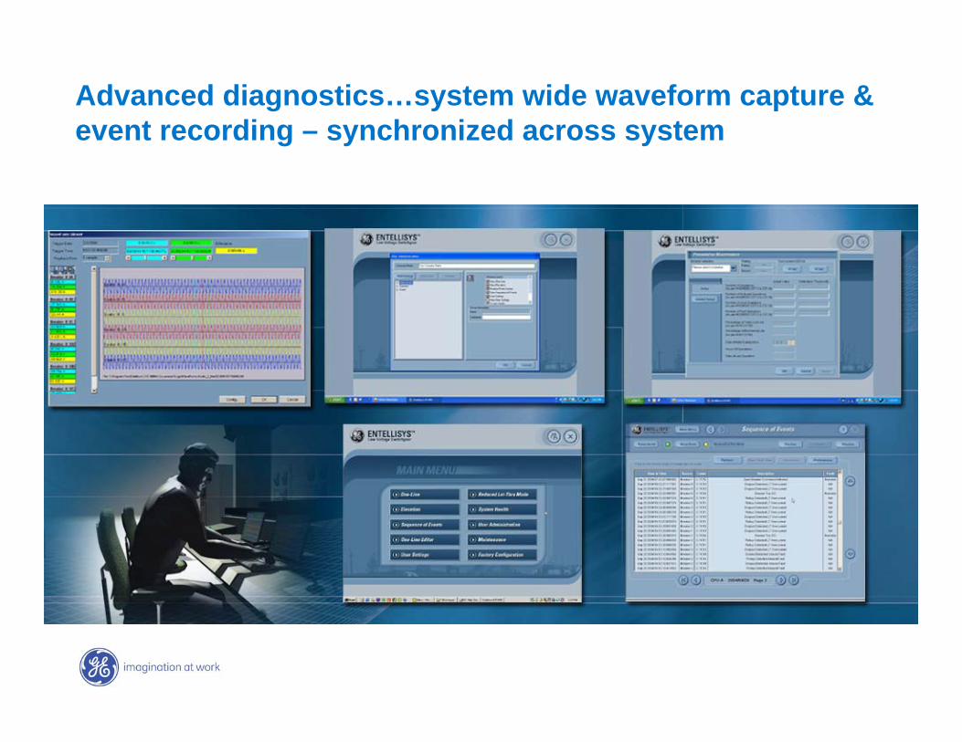
Advanced diagnostics…system wide waveform capture & event recording – synchronized across system
GE7 December 2004
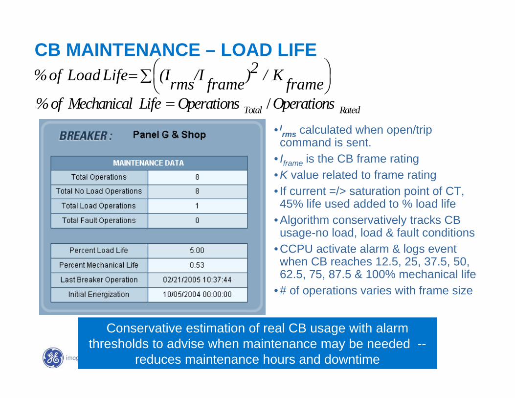
CB MAINTENANCE – LOAD LIFE
• Irms calculated when open/trip command is sent.
• Iframe is the CB frame rating • K value related to frame rating• If current =/> saturation point of CT, 45% life used added to % load life
• Algorithm conservatively tracks CB usage-no load, load & fault conditions
• CCPU activate alarm & logs event when CB reaches 12.5, 25, 37.5, 50, 62.5, 75, 87.5 & 100% mechanical life
• # of operations varies with frame size
∑ ⎟⎠⎞⎜
⎝⎛= frameK / 2)frame/Irms(I Life Load of %
Conservative estimation of real CB usage with alarm thresholds to advise when maintenance may be needed --
reduces maintenance hours and downtime
RatedTotal OperationsOperations / Life Mechanical of % =
GE7 December 2004
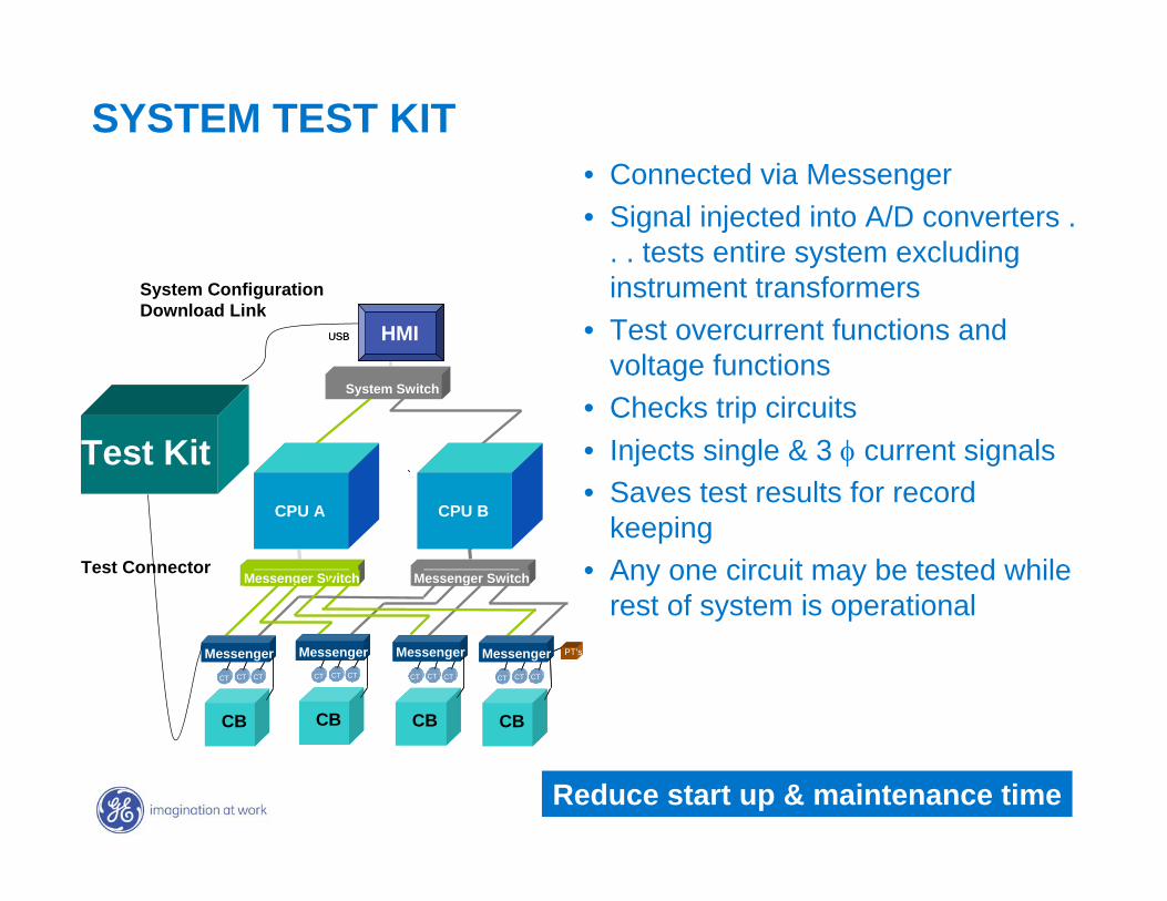
SYSTEM TEST KIT• Connected via Messenger• Signal injected into A/D converters .
. . tests entire system excluding instrument transformers
• Test overcurrent functions and voltage functions
• Checks trip circuits• Injects single & 3 φ current signals• Saves test results for record
keeping• Any one circuit may be tested while
rest of system is operational
Test Kit
System ConfigurationDownload Link
Test Connector
CPU A CPU B
PT’s
Breaker
Messenger
CT CT CT
Breaker
Messenger
CT CT CT
Breaker
Messenger
CT CT CT
Breaker
Messenger
CT CT CT
Messenger SwitchMessenger Switch
HMIUSB
System Interface Ethernet Switch
CPU A CPU B
PT’s
CB
MessengerCTCT CTCT CTCT
CB
MessengerCTCT CTCT CTCT
CB
MessengerCTCT CTCT CTCT
CB
MessengerCTCT CTCT CTCT
Messenger SwitchMessenger SwitchMessenger SwitchMessenger Switch
HMIUSB
System Switch
Reduce start up & maintenance time
GE7 December 2004
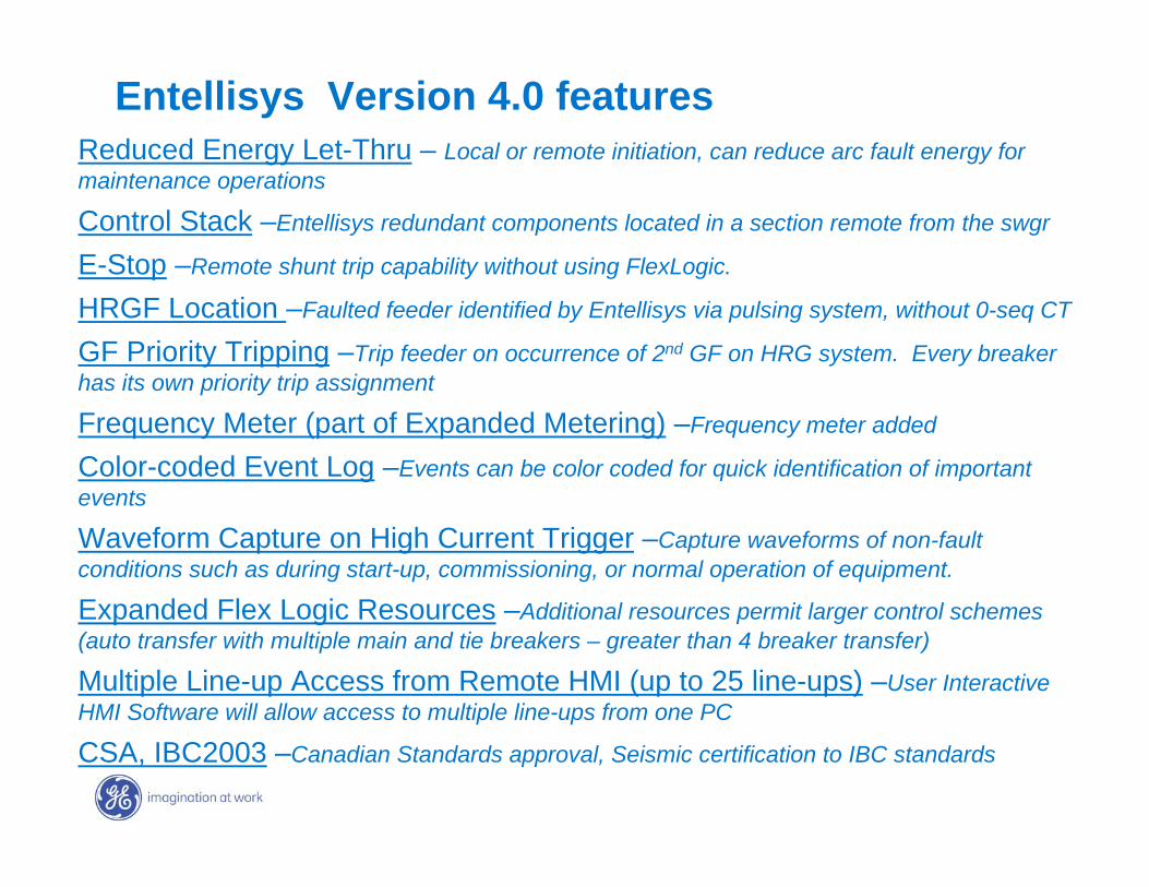
Entellisys Version 4.0 featuresReduced Energy Let-Thru – Local or remote initiation, can reduce arc fault energy for maintenance operations
Control Stack –Entellisys redundant components located in a section remote from the swgr
E-Stop –Remote shunt trip capability without using FlexLogic.
HRGF Location –Faulted feeder identified by Entellisys via pulsing system, without 0-seq CT
GF Priority Tripping –Trip feeder on occurrence of 2nd GF on HRG system. Every breaker has its own priority trip assignment
Frequency Meter (part of Expanded Metering) –Frequency meter added
Color-coded Event Log –Events can be color coded for quick identification of important events
Waveform Capture on High Current Trigger –Capture waveforms of non-fault conditions such as during start-up, commissioning, or normal operation of equipment.
Expanded Flex Logic Resources –Additional resources permit larger control schemes (auto transfer with multiple main and tie breakers – greater than 4 breaker transfer)
Multiple Line-up Access from Remote HMI (up to 25 line-ups) –User Interactive HMI Software will allow access to multiple line-ups from one PC
CSA, IBC2003 –Canadian Standards approval, Seismic certification to IBC standards

GE7 December 2004
GE7 December 2004
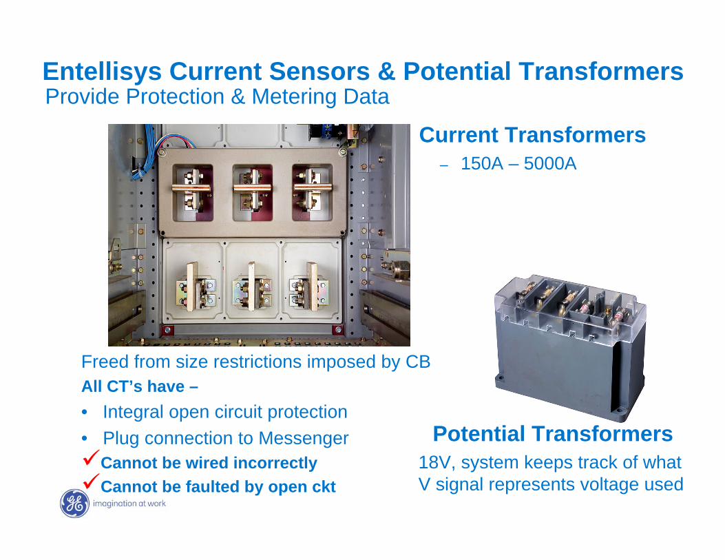
Current Transformers– 150A – 5000A
Potential Transformers18V, system keeps track of what V signal represents voltage used
Entellisys Current Sensors & Potential TransformersProvide Protection & Metering Data
Freed from size restrictions imposed by CBAll CT’s have –• Integral open circuit protection• Plug connection to Messenger
Cannot be wired incorrectlyCannot be faulted by open ckt
GE7 December 2004
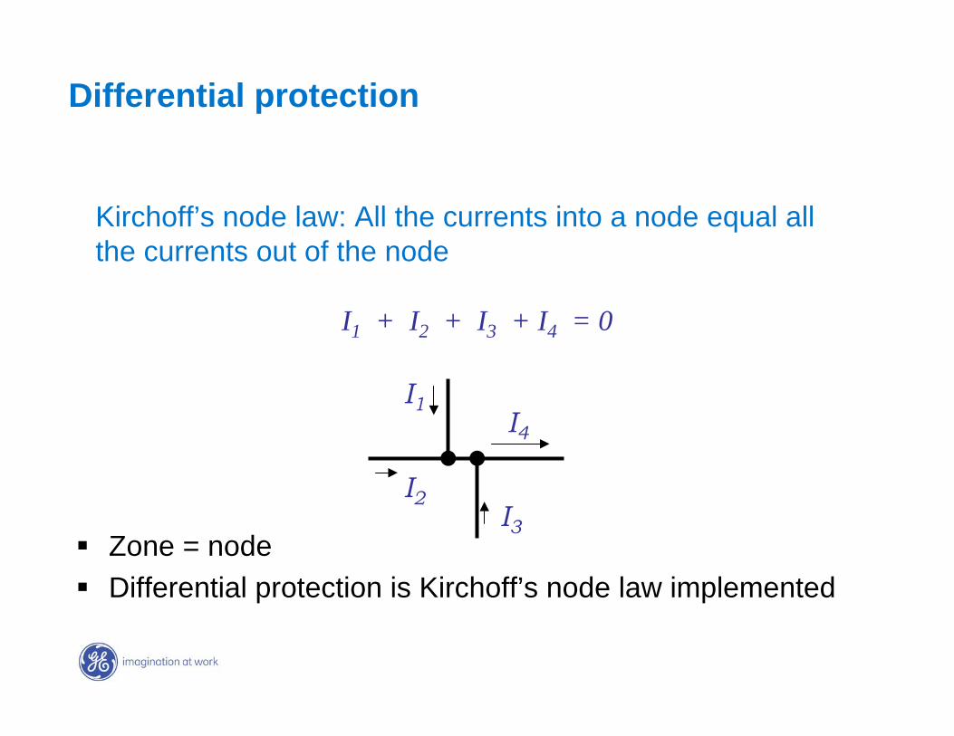
Zone = nodeDifferential protection is Kirchoff’s node law implemented
Kirchoff’s node law: All the currents into a node equal all the currents out of the node
I1 + I2 + I3 + I4 = 0
I3
I1I4
I2
Differential protection

GE7 December 2004
Entellisys DynamicTrip Time Curve
0.01
0.1
1
10
100
1000
100 1000 10000 100000Current Amps
Tim
e (s
econ
ds)
4kA Main4kA Tie1600A Fdr All CB set to provide optimized
protection for their zone• sustain loads & detect overloads
Overlapping devices selective protection is location based. Cascaded time delays not requiredEach CB set for faults or overloads in its protection zone
Feeder with Instantaneous
Tie with Short time at minimum
Main with short time at minimum
You set CB to protect circuit
Entellisys coordinates
GE7 December 2004
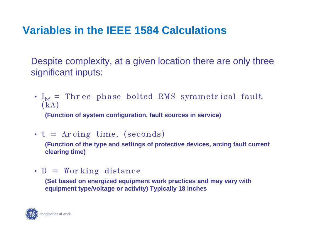
Variables in the IEEE 1584 Calculations
Despite complexity, at a given location there are only three significant inputs:
• Ibf = Three phase bolted RMS symmetrical fault (kA)
(Function of system configuration, fault sources in service)
• t = Arcing time, (seconds)(Function of the type and settings of protective devices, arcing fault current clearing time)
• D = Working distance(Set based on energized equipment work practices and may vary with equipment type/voltage or activity) Typically 18 inches
GE7 December 2004
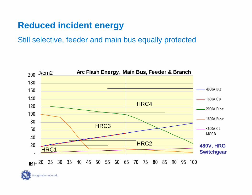
Arc Flash Energy, Main Bus, Feeder & Branch
-20406080
100120140160180200
20 25 30 35 40 45 50 55 60 65 70 75 80 85 90 95 100IBF
J/cm2
4000A Bus
1600A CB
2000A Fuse
1600A Fuse
<600A CLMCCB
480V, HRGSwitchgear
Reduced incident energyStill selective, feeder and main bus equally protected
HRC4
HRC3
HRC2HRC1
GE7 December 2004
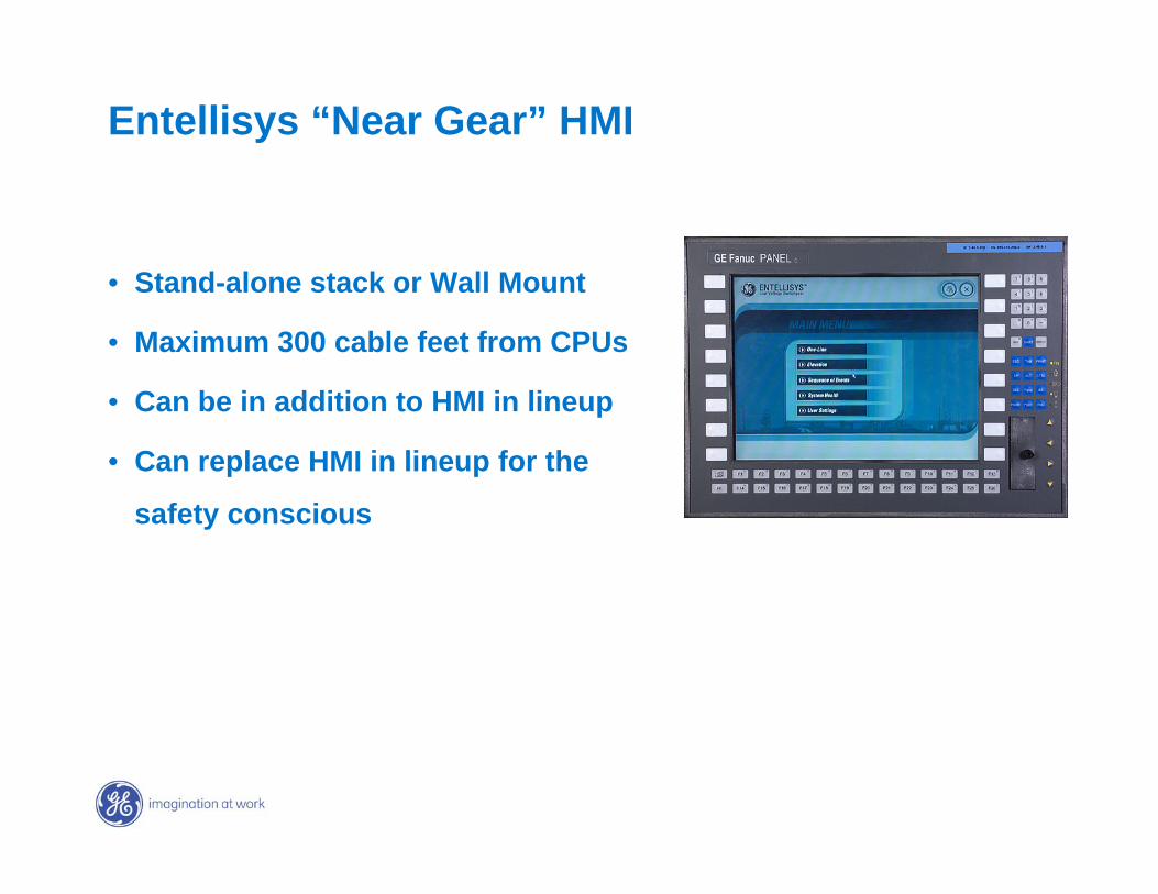
Entellisys “Near Gear” HMI
• Stand-alone stack or Wall Mount
• Maximum 300 cable feet from CPUs
• Can be in addition to HMI in lineup
• Can replace HMI in lineup for the
safety conscious
GE7 December 2004
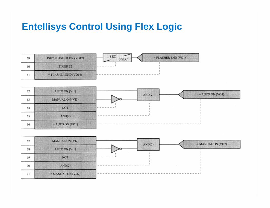
Entellisys Control Using Flex Logic
GE7 December 2004
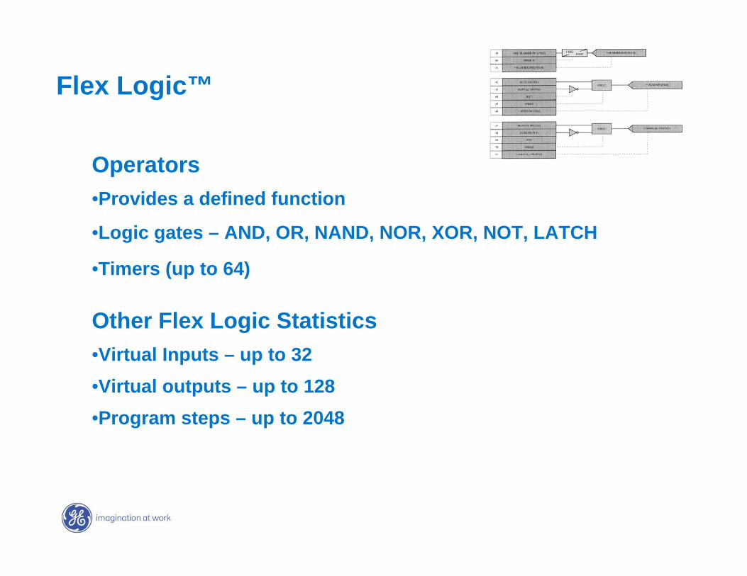
Operators •Provides a defined function
•Logic gates – AND, OR, NAND, NOR, XOR, NOT, LATCH
•Timers (up to 64)
Other Flex Logic Statistics•Virtual Inputs – up to 32•Virtual outputs – up to 128•Program steps – up to 2048
Flex Logic™


![SAN]OSE CITYOF MemorandumFeeder from Switchgear M5 to Switchgear S16B 6. Feeder from Switchgear M5 to Switchgear ESB Engineer'sEstimate $384,787 $77,720 $211,326 $747,139 ... Ifthisproject](https://img.dokumen.tips/doc/110x75/5e7fcbe33356ee7623111eaf/sanose-cityof-feeder-from-switchgear-m5-to-switchgear-s16b-6-feeder-from-switchgear.jpg)