Embed Size (px)
Citation preview

Application Note ENT-AN1115
Layer 2 Protocol Configuration
This document describes how to configure Microsemi Switch Engines to perform Layer 2 functions suchas Link Aggregation (LAG), Link Aggregation Control Protocol (LACP), Virtual LANs (VLANs), Mirroring,Generic VLAN Registration Protocol (GVRP), and Multiple Spanning Tree Protocol (MSTP).Configuration examples are provided both for the command line interface (CLI) and the Web GUI.
Table of Contents
AggregationAggregation enables the use of multiple ports in parallel to increase the link speed beyond the limits of asingle port, and to increase the redundancy for higher availability. If the system has 6 ports, the maximumaggregation group is 3 (6 divided by 2).
Adding a Port to an Aggregation Group
CLI Example: Add the first Gigabit port into group 1# configure terminal(config)# interface GigabitEthernet 1/1(config-if)# aggregation ? group Create an aggregation group (config-if)# aggregation group<uint>
Aggregation . . . . . . . . . . . . . . . . . . . . . . . . . . . . . . . . . . . . . . . . . . . . . . . . 1LACP . . . . . . . . . . . . . . . . . . . . . . . . . . . . . . . . . . . . . . . . . . . . . . . . . . . 3MAC Address Table . . . . . . . . . . . . . . . . . . . . . . . . . . . . . . . . . . . . . . . . . . . . 6VLAN . . . . . . . . . . . . . . . . . . . . . . . . . . . . . . . . . . . . . . . . . . . . . . . . . . . 8Mirroring and Remote Mirroring . . . . . . . . . . . . . . . . . . . . . . . . . . . . . . . . . . . . . 18GVRP . . . . . . . . . . . . . . . . . . . . . . . . . . . . . . . . . . . . . . . . . . . . . . . . . . 27Multiple Spanning Tree Protocol . . . . . . . . . . . . . . . . . . . . . . . . . . . . . . . . . . . . 31
July 2015 1
© 2015 Microsemi Corporation

Layer 2 Protocol Configuration Layer 2 Protocol Configuration
(config-if)# aggregation group 1
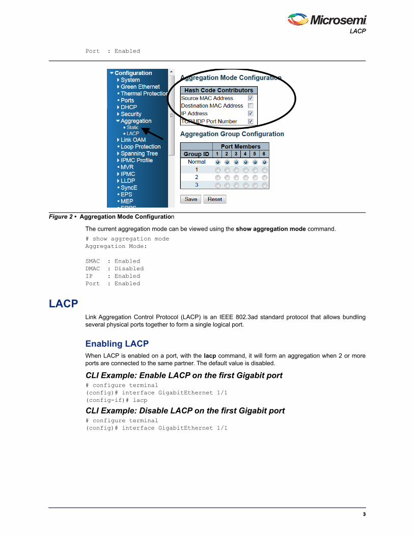
Configuring the Aggregation ModeThe aggregation feature uses the following keys to calculate the destination port for the frame. Thedefault method is the source MAC address, IP address, and TCP/UDP port number. The destinationMAC address is not used in the default case.
CLI Example: Change aggregation mode to dmac, ip, port, and smac# configure terminal(config)# aggregation mode ? dmac Destination MAC affects the distribution ip IP address affects the distribution port IP port affects the distribution smac Source MAC affects the distribution <cr>(config)# aggregation mode dmac ip port smac(config)# do show aggregation modeAggregation Mode:
SMAC : EnabledDMAC : EnabledIP : Enabled
Figure 1 • Aggregation Group Configuration
22
LACPLACP
Port : Enabled
The current aggregation mode can be viewed using the show aggregation mode command.
# show aggregation modeAggregation Mode:
SMAC : EnabledDMAC : DisabledIP : EnabledPort : Enabled
LACPLink Aggregation Control Protocol (LACP) is an IEEE 802.3ad standard protocol that allows bundlingseveral physical ports together to form a single logical port.
Enabling LACPWhen LACP is enabled on a port, with the lacp command, it will form an aggregation when 2 or moreports are connected to the same partner. The default value is disabled.
CLI Example: Enable LACP on the first Gigabit port# configure terminal(config)# interface GigabitEthernet 1/1(config-if)# lacp
CLI Example: Disable LACP on the first Gigabit port# configure terminal(config)# interface GigabitEthernet 1/1
Figure 2 • Aggregation Mode Configuration
33

Layer 2 Protocol Configuration Layer 2 Protocol Configuration
(config-if)# no lacp
Configuring the KeyThe port’s LACP key ranges from 1-65535. The Auto setting sets the key according to the physical linkspeed, 10 Mb = 1, 100 Mb = 2, 1 Gb = 3. With a specific setting a user-defined value can be entered.Ports with the same key can participate in the same aggregation group while ports with different keyscannot. The default value is auto.
CLI Example: Set LACP key to 3 on the first Gigabit port# configure terminal(config)# interface GigabitEthernet 1/1(config-if)# lacp key ? <1-65535> Key value auto Choose a key based on port speed(config-if)# lacp key 3
Configuring the RoleLACP role shows the activity status. An Active role transmits LACP packets each second, while Passivewaits for an LACP packet from a partner, also known as the “speak if spoken to” role. The default value isactive.
CLI Example: Set LACP Role to Passive on the first Gigabit port# configure terminal(config)# interface GigabitEthernet 1/1(config-if)# lacp role ? active Transmit LACP BPDUs continously
Figure 3 • LACP Enabled Configuration
Figure 4 • LACP Key Configuration
44
LACPLACP
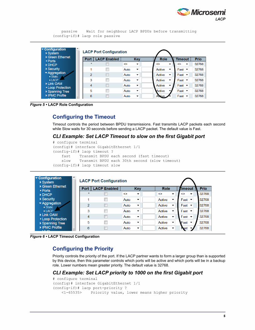
passive Wait for neighbour LACP BPDUs before transmitting(config-if)# lacp role passive
Configuring the TimeoutTimeout controls the period between BPDU transmissions. Fast transmits LACP packets each secondwhile Slow waits for 30 seconds before sending a LACP packet. The default value is Fast.
CLI Example: Set LACP Timeout to slow on the first Gigabit port # configure terminal(config)# interface GigabitEthernet 1/1(config-if)# lacp timeout ? fast Transmit BPDU each second (fast timeout) slow Transmit BPDU each 30th second (slow timeout)(config-if)# lacp timeout slow
Configuring the PriorityPriority controls the priority of the port. If the LACP partner wants to form a larger group than is supportedby this device, then this parameter controls which ports will be active and which ports will be in a backuprole. Lower numbers mean greater priority. The default value is 32768.
CLI Example: Set LACP priority to 1000 on the first Gigabit port # configure terminal(config)# interface GigabitEthernet 1/1(config-if)# lacp port-priority ? <1-65535> Priority value, lower means higher priority
Figure 5 • LACP Role Configuration
Figure 6 • LACP Timeout Configuration
55

Layer 2 Protocol Configuration Layer 2 Protocol Configuration
(config-if)# lacp port-priority 1000
Showing the Status The current LACP mode can be viewed with the show lacp command, as follows:
# show lacp ? internal Internal LACP configuration neighbour Neighbour LACP status statistics Internal LACP statistics system-id LACP system id
MAC Address TableSwitching is based upon the DMAC address contained in the frame. The switch builds up a table thatmaps MAC addresses to switch ports for knowing which ports the frames should go to. This tablecontains both static and dynamic entries. The static entries are configured by the network administrator ifthe administrator wants to do a fixed mapping between the DMAC address and switch ports.
The frames also contain a source MAC address (SMAC address), which shows the MAC address of theequipment sending the frame. The SMAC address is used by the switch to automatically update the MACtable with these dynamic MAC addresses. Dynamic entries are removed from the MAC table if no framewith the corresponding SMAC address has been seen after a configurable age time.
Setting the Aging TimeBy default, dynamic entries are removed from the MAC table after 300 seconds. This removal is calledaging.
CLI Example: Change the aging time to 600 seconds# configure terminal(config)#(config)# mac address-table aging-time ? <0,10-1000000> Aging time in seconds, 0 disables aging
Figure 7 • LACP Priority Configuration
66

MAC Address TableMAC Address Table
(config)# mac address-table aging-time 600
Adding a Static MAC Address Entry
CLI Example: Add the static MAC address: 00:00:00:00:00:01 in VLAN 2 on the first Gigabit port# configure terminal(config)#(config)# mac address-table ? aging-time Mac address aging time static Static MAC address(config)# mac address-table static 00:00:00:00:00:01 vlan 2 interface GigabitEthernet 1/1
Figure 8 • MAC Address Table Aging Configuration
Figure 9 • Static MAC Address Configuration
77

Layer 2 Protocol Configuration Layer 2 Protocol Configuration
Showing the MAC Address Table The current MAC address table can be viewed with the show mac address-table command as follows:
# show mac address-table
VLANThe following illustration shows an example VLAN configuration.
Because VLAN 1 is created by default, one need only add VLAN 2 and 3, as follows:
# configure terminal(config)# vlan 2(config)# vlan 3Set the access port. Assume that port 1 through3 are connected to the PC. The PVID of each port isdifferent.
# configure terminal(config)# interface GigabitEthernet 1/1(config-if)# switchport mode access(config-if)# switchport access vlan 1(config)# exit
Figure 10 • MAC Address Table
Figure 11 • VLAN Quick Configuration Example
VLAN 1 VLAN 2 VLAN 3
Switch 1
Switch 2
Switch 3
88

VLANVLAN
(config)# interface GigabitEthernet 1/2(config-if)# switchport mode access(config-if)# switchport access vlan 2(config)# exit(config)# interface GigabitEthernet 1/3(config-if)# switchport mode access(config-if)# switchport access vlan 3(config)# exitSet the trunk port. Assume that port 4 is connected to the other switch. Set the allowed VLAN to accept1-3.
# configure terminal(config)# interface GigabitEthernet 1/4(config-if)# switchport mode trunk(config-if)# switchport trunk allowed vlan 1-3Configure the port such that frames are always transmitted with a tag on port 4.(config-if)# switchport trunk vlan tag native
Global Configuration
Existing VLANCLI Example: Adding VLAN 2# configure terminal(config)# vlan 2
CLI Example: Removing VLAN 2# configure terminal(config)# no vlan 2
CLI Example: Show existing VLANs# show vlan briefVLAN Name Interfaces---- -------------------------------- ----------1 default Gi 1/1-62 VLAN0002The Allowed Access VLAN field only affects ports configured as access ports. Ports in other modes aremembers of all VLANs specified in the allowed VLANs field . By default, only VLAN 1 is enabled. MoreVLANs may be created by using the following list syntax.
# configure terminal(config)# vlan1,10-13,200,300Individual elements are separated by commas and ranges are specified with a dash separating the lowerand upper bound. Spaces are allowed in between the delimiters. The example creates VLANs 1, 10, 11,12, 13, 200, and 300.
Figure 12 • VLAN Allowed Access VLANs Configuration
99

Layer 2 Protocol Configuration Layer 2 Protocol Configuration
VLAN NamingCLI Example: Set VLAN2’s name to test # configure terminal(config)# vlan 2(config-vlan)# name test
Web GUINot available.
Ethertype for Custom S-portsThis field specifies the Ethertype/TPID (specified in hexadecimal) of tagged frames. The setting appliesto all ports whose Port Type is set to S-Custom-Port. It takes effect on the egress side.
CLI Example # configure terminal(config)# vlan ethertype s-custom-port <0x0600-0xffff>
Port Based Configuration
Port ModePort mode determines the fundamental behavior of the port in question. A port can be in one of threemodes, with Access being the default.
AccessAccess ports are normally used to connect to end stations. Dynamic features like Voice VLAN may addthe port to more VLANs behind the scenes. Access ports have the following characteristics:
• Member of exactly one VLAN, the Port LAN or Access VLAN, which by default is 1
• Accepts untagged frames and C-tagged frames
• Discards all frames that are not classified to the Access VLAN
• Upon egress all frames are transmitted untagged
Trunk Trunk ports can carry traffic on multiple VLANs simultaneously, and are normally used to connect to otherswitches. Trunk ports have the following characteristics.
• Member of all existing VLANs by default (limited by the use of allowed VLANs)
• All frames except those classified to the Port VLAN or Native VLAN get tagged on egress bydefault (frames classified to the Port VLAN do not get C-tagged on egress)
• Egress tagging can be changed to tag all frames, in which case only tagged frames are acceptedon ingress
Figure 13 • VLAN Ethertype for Custom S-ports Configuration
1010

VLANVLAN
Hybrid:Hybrid ports resemble trunk ports in many ways while including additional port configuration features. Inaddition to the characteristics described for trunk ports, hybrid ports have the following abilities.
• Can be configured to be VLAN tag unaware, C-tag aware, S-tag aware, or S-custom-tag aware
• Ingress filtering can be controlled
• Ingress acceptance of frames and configuration of egress tagging can be configuredindependently
CLI Example: Configure as Access port on the first Gigabit port # configure terminal(config)# interface GigabitEthernet 1/1 (config-if)# switchport mode access
CLI Example: Configure as Trunk port on the first Gigabit port # configure terminal (config)# interface GigabitEthernet 1/1 (config-if)# switchport mode trunk
CLI Example: Configure as Hybrid port on the first Gigabit port # configure terminal(config)# interface GigabitEthernet 1/1 (config-if)# switchport mode hybrid
Port VLAN Port VLAN determines the port's VLAN ID, or PVID. Allowed VLANs are in the range of 1 through 4095,with the default being 1.
On ingress, frames get classified to the Port VLAN if the port is configured as VLAN unaware, the frameis untagged, or VLAN awareness is enabled on the port, but the frame is priority tagged (VLAN ID = 0).
On egress, frames classified to the Port VLAN do not get tagged if Egress Tagging is set to untag portVLAN.
Port VLAN is called an Access VLAN for ports in access mode and Native VLAN for ports in trunk orhybrid mode.
CLI Example: Set Port VLAN to 2 on the first Gigabit port (configured as access mode)# configure terminal(config)# interface GigabitEthernet 1/1(config-if)# switchport access vlan 2 <vlan_id> VLAN ID of the native VLAN when this port is in trunk mode
CLI Example: Set Port VLAN to 2 on the first Gigabit port (configured as trunk mode)# configure terminal (config)# interface GigabitEthernet 1/1 (config-if)# switchport trunk native vlan 2
Figure 14 • VLAN Mode Configuration
1111

Layer 2 Protocol Configuration Layer 2 Protocol Configuration
CLI Example: Set Port VLAN to 2 on the first Gigabit port (configured as hybrid mode) # configure terminal(config)# interface GigabitEthernet 1/1 (config-if)# switchport hybrid native vlan 2
Port Type Ports in hybrid mode allow for changing the port type, that is, whether a frame's VLAN tag is used toclassify the frame on ingress to a particular VLAN, and if so, which TPID it reacts on. Likewise, onegress, the port type determines the TPID of the tag, if a tag is required.
Unaware On ingress, all frames, whether carrying a VLAN tag or not, get classified to the Port VLAN, and possibletags are not removed on egress.
C-Port On ingress, frames with a VLAN tag with TPID = 0x8100 get classified to the VLAN ID embedded in thetag. If a frame is untagged or priority tagged, the frame gets classified to the Port VLAN. If frames mustbe tagged on egress, they are tagged with a C-tag.
S-PortOn ingress, frames with a VLAN tag with TPID = 0x8100 or 0x88A8 get classified to the VLAN IDembedded in the tag. If a frame is untagged or priority tagged, the frame gets classified to the Port VLAN.If frames must be tagged on egress, they will be tagged with an S-tag.
S-Custom-PortOn ingress, frames with a VLAN tag with a TPID = 0x8100 or equal to the Ethertype configured forCustom-S ports get classified to the VLAN ID embedded in the tag. If a frame is untagged or prioritytagged, the frame gets classified to the Port VLAN. If frames must be tagged on egress, they will betagged with the custom S-tag.
CLI Example: Set Port Type on the first Gigabit port# configure terminal(config)# interface GigabitEthernet 1/1(config-if)# switchport hybrid port-type ? c-port Customer port s-custom-port Custom Provider port s-port Provider port
Figure 15 • VLAN PVID Configuration
1212

VLANVLAN
unaware Port in not aware of VLAN tags
Ingress Filtering Hybrid ports allow for changing ingress filtering. Access and trunk ports always have ingress filteringenabled.
If ingress filtering is enabled, frames classified to a VLAN that the port is not a member of get discarded.
If ingress filtering is disabled, frames classified to a VLAN that the port is not a member of are acceptedand forwarded to the switch engine. However, the port will never transmit frames classified to VLANs thatit is not a member of.
CLI Example: Set ingress filtering on the first Gigabit port # configure terminal(config)# interface GigabitEthernet 1/1(config-if)# switchport hybrid ? acceptable-frame-type Set acceptable frame type on a port allowed Set allowed VLAN characteristics when interface is in hybrid mode egress-tag Egress VLAN tagging configuration ingress-filtering VLAN Ingress filter configuration native Set native VLAN port-type Set port type
Ingress Acceptance Hybrid ports allow for changing the type of frames that are accepted on ingress.
Figure 16 • VLAN Port Type Configuration
Figure 17 • VLAN Ingress Filtering Configuration
1313

Layer 2 Protocol Configuration Layer 2 Protocol Configuration
Tagged and UntaggedBoth tagged and untagged frames are accepted.
Tagged Only Only tagged frames are accepted on ingress. Untagged frames are discarded.
Untagged Only Only untagged frames are accepted on ingress. Tagged frames are discarded.
CLI Example: Configure ingress filtering on the first Gigabit port# configure terminal(config)# interface GigabitEthernet 1/1(config-if)# switchport hybrid acceptable-frame-type ? all Allow all frames tagged Allow only tagged frames untagged Allow only untagged frames
Egress Tagging Ports in Trunk and Hybrid mode may control the tagging of frames on egress.
Untag Port VLAN Frames classified to the Port VLAN are transmitted untagged. Other frames are transmitted with therelevant tag.
Tag AllAll frames, whether classified to the Port VLAN or not, are transmitted with a tag.
Untag All All frames, whether classified to the Port VLAN or not, are transmitted without a tag. This option is onlyavailable for ports in Hybrid mode.
CLI Example: Set egress tagging on the first Gigabit port # configure terminal(config)# interface GigabitEthernet 1/1(config-if)# switchport hybrid egress-tag ? all Tag all frames
Figure 18 • VLAN Ingress Acceptance Configuration
1414

VLANVLAN
none No egress tagging
Allowed VLANs Ports in Trunk and Hybrid mode may control which VLANs they are allowed to become members of.Access ports can only be members of the Access VLAN.
The field's syntax is identical to the syntax used in the Existing VLANs field. By default, a port maybecome a member of all possible VLANs, and is therefore set to 1-4095.
The field may be left empty, which means that the port will not be member of any of the existing VLANs.
CLI Example: Set port VLAN to 2 on the first Gigabit port (configured as trunk mode) # configure terminal(config)# interface GigabitEthernet 1/1(config-if)# switchport trunk allowed vlan ? <vlan_list> VLAN IDs of the allowed VLANs when this port is in hybrid mode add Add VLANs to the current list all All VLANs except All VLANs except the following none No VLANs remove Remove VLANs from the current list
CLI Example: Set port VLAN to 2 on the first Gigabit port (configured as hybrid mode) # configure terminal (config)# interface GigabitEthernet 1/1 (config-if)# switchport hybrid allowed vlan ? <vlan_list> VLAN IDs of the allowed VLANs when this port is in hybrid mode add Add VLANs to the current list all All VLANs except All VLANs except the following none No VLANs
Figure 19 • VLAN Egress Tagging Configuration
1515

Layer 2 Protocol Configuration Layer 2 Protocol Configuration
remove Remove VLANs from the current list
Forbidden VLANs A port may be configured to never be a member of one or more VLANs. This is particularly useful whendynamic VLAN protocols such as MVRP and GVRP must be prevented from dynamically adding ports toVLANs.
The trick is to mark such VLANs as forbidden on the port in question. The syntax is identical to the syntaxused in the Existing VLANs field.
By default, the field is left blank, which means that the port may become a member of all possible VLANs.
CLI Example: Configure forbidden VLAN on the first Gigabit port # configure terminal(config)# interface GigabitEthernet 1/1(config-if)# switchport forbidden vlan ? add Add to existing list. remove Remove from existing list.
Show VLAN StatusCLI Example # show vlan ? brief VLAN summary information id VLAN status by VLAN id ip-subnet Show VLAN ip-subnet entries. mac Show VLAN MAC entries.
Figure 20 • Allowed VLANs Configuration
Figure 21 • Forbidden VLANs Configuration
1616

VLANVLAN
name VLAN status by VLAN name protocol Protocol-based VLAN status status Show the VLANs configured for each interface. <cr>
Web GUIVarious internal software modules may use VLAN services to configure VLAN memberships such asNAS, GVRP, MVR, Voice VLAN, MEP, or EVC.
The drop-down list on the right allows for selecting between showing VLAN memberships as configuredby an administrator (Admin) or as configured by one of these internal software modules.
The Combined entry will show a combination of the administrator and internal software moduleconfiguration to reflect what is actually configured in hardware.
Figure 22 • VLAN Membership Status
Figure 23 • VLAN Port Status
1717

Layer 2 Protocol Configuration Layer 2 Protocol Configuration
Mirroring and Remote Mirroring
Local MirroringFor debugging network problems or monitoring network traffic, the switch system can be configured tomirror frames from multiple ports to a mirror port.
Mirror the Traffic of Port X to Port Y1. Enable Mirror session
# configure terminal(config)# monitor session 1
2. Mirror the traffic (both rx and tx) of the first Gigabit port
(config)# monitor session 1 source interface GigabitEthernet 1/1 both3. Configure the mirror destination port to Gigabit port 6
(config)# monitor session 1 destination interface GigabitEthernet 1/64. Verify the monitor setting
(config)# end # show monitor session 1 Session 1 --------- Mode : Enabled Type : Mirror Source VLAN(s) : Source Ports : Both : 1/1 Destination Ports : 1/6 Disable Mirror session # configure terminal (config)# no monitor session 1
Mirror the Traffic of VLAN N to Port Y1. Enable Mirror session
# configure terminal(config)# monitor session 1
Figure 24 • Mirror Traffic of Port 1 to Port 6
1818

Mirroring and Remote MirroringMirroring and Remote Mirroring
2. Mirror the traffic of VLAN 123
(config)# monitor session 1 source vlan 1233. Configure the mirror destination port to Gigabit port 6
(config)# monitor session 1 destination interface GigabitEthernet 1/6
Remote Mirroring Remote Mirroring is an extended function of Mirroring. It can extend the destination port in otherswitches. So the administrator can analyze the network traffic on the other switches.
Switch 1Configure switch 1 as the source switch with the following parameters
• Source port: 1
• Mirror mode: both, frames received and frames transmitted are mirrored.
• Intermediate port: 4
Note: The intermediate port needs to disable MAC table learning.
• Reflector port: 2
Note: The reflector port needs to select only on Source switch type.
Note: The reflector port needs to disable MAC Table learning and STP.
Note: The reflector port is only supported on pure copper ports.
• VLAN for mirrored traffic: 200
CLI Example: Remote mirroring - source switch configuration# configure terminal(config)# monitor session 1
Figure 25 • Mirror Traffic of VLAN 123 to Port 6
Figure 26 • Remote Mirroring
Switch 1 Switch 2 Switch 3
NetworkUser
Port 1 Port 4 Port 3 Port 4Port 4 Port 1
Administrator
1919

Layer 2 Protocol Configuration Layer 2 Protocol Configuration
(config)# monitor session 1 source interface GigabitEthernet 1/1 both(config)# monitor session 1 intermediate interface GigabitEthernet 1/4(config)# monitor session 1 destination remote vlan 200 reflector-port GigabitEthernet 1/2(config)# interface GigabitEthernet 1/2(config-if)# no spanning-tree(config-if)# no mac address-table learning
Switch 2 Configure switch 2 as Intermediate switch with the following parameters.
• Intermediate port: 3 and 4
Note: The intermediate port needs to disable MAC Table learning.
• VLAN for mirrored traffic: 200
CLI Example: Remote mirroring - intermediate switch configuration # configure terminal(config)# monitor session 1(config)# monitor session 1 intermediate interface GigabitEthernet 1/3-4(config)# monitor session 1 intermediate remote vlan 200(config)# interface GigabitEthernet 1/3-4
Figure 27 • Remote Mirroring- Source Switch
2020

Mirroring and Remote MirroringMirroring and Remote Mirroring
(config-if)# no mac address-table learning
Switch 3 Configure switch 3 as the destination switch with the following parameters.
• Intermediate port: 4
Note: The intermediate port needs to disable MAC Table learning.
• Destination port: 1
Note: The device only supports one destination port.
Note: The destination port needs to disable MAC Table learning.
• VLAN for mirrored traffic: 200
CLI Example: Remote mirroring - destination switch # configure terminal(config)# monitor session 1(config)# monitor session 1 destination interface GigabitEthernet 1/1(config)# monitor session 1 intermediate interface GigabitEthernet 1/4(config)# monitor session 1 source remote vlan 200(config)# interface GigabitEthernet 1/1,4
Figure 28 • Remote Mirroring- Intermediate Switch
2121

Layer 2 Protocol Configuration Layer 2 Protocol Configuration
(config-if)# no mac address-table learning
Configuration Options
Type Mirror Configure the switch to local mirror mode. The source port(s) and destination port are located on thesame switch.
SourceConfigure the switch as a source node for monitor flow. The source port(s), reflector port andintermediate port(s) are located on this switch.
Intermediate Configure the switch as a forwarding node for monitor flow and the switch is an option node. The objectis to forward traffic from source switch to destination switch. The intermediate ports are located on thisswitch.
Figure 29 • Remote Mirroring- Destination Switch
2222

Mirroring and Remote MirroringMirroring and Remote Mirroring
DestinationConfigure the switch as an end node for monitor flow. The destination port(s) and intermediate port(s) arelocated on this switch.
Figure 30 • Mirroring Type
2323

Layer 2 Protocol Configuration Layer 2 Protocol Configuration
VLAN ID The VLAN ID points out where the monitor packet will copy to. It is recommend to be separate from theVLAN of normal data traffic.
Reflector Port The reflector port is a method to redirect traffic to the remote mirroring VLAN. The reflector port will stopworking as a normal port if it is configured as a reflector port.
Note: The reflector port needs to select only on Source switch type.
Note: The reflector port needs to disable MAC Table learning and STP.
Note: The reflector port only supports on pure copper ports.
Source VLAN(s) ConfigurationThe switch can support VLAN-based mirroring.
Figure 31 • Remote Mirroring- VLAN ID
Figure 32 • Remote Mirroring- Reflector Port
2424

Mirroring and Remote MirroringMirroring and Remote Mirroring
Note: The mirroring session may have either ports or VLANs as sources, but not both.
Remote Mirroring Port Configuration Source
• Disabled: Neither frames transmitted nor frames received are mirrored.
• Both: Frames received and frames transmitted are mirrored on the Intermediate/Destination port.
• Rx only: Frames received on this port are mirrored on the Intermediate/Destination port. Framestransmitted are not mirrored.
• Tx only: Frames transmitted on this port are mirrored on the Intermediate/Destination port.Frames received are not mirrored.
Intermediate For remote mirroring only, the intermediate port is a switched port to connect to other switch.
Note: The intermediate port needs to disable MAC table learning.
Destination The destination port is a switched port that you receive a copy of traffic from the source port.
Note: On mirror mode, the device only supports one destination port.
Figure 33 • Mirroring Source VLAN
2525

Layer 2 Protocol Configuration Layer 2 Protocol Configuration
Note: The destination port needs to disable MAC table learning.
Configuration Guideline for All Features When the switch is running in Remote Mirroring mode, the administrator needs to check whether or notother features are enabled or disabled. For example, the administrator cannot enable the MSTP on areflector port. All monitor traffic is blocked on the reflector port.
The following table lists the recommended settings.
Figure 34 • Mirroring Port Configuration
Table 1 • Configuration Guideline for All Features
Feature ImpactSource Port
Reflector Port
Intermediate Port
Destination Port
Remote Mirroring VLAN
arp_inspection High disabled* disabled*
acl Critical disabled* disabled* disabled*
dhcp_relay High disabled* disabled*
dhcp_snooping High disabled* disabled*
ip_source_guard Critical disabled* disabled* disabled*
ipmc/igmpsnp Critical un-conflict
ipmc/mldsnp Critical un-conflict
lacp Low disabledo
lldp Low disabledo
mac learning Critical disabled* disabled* disabled*
mstp Critical disabled* disabledo
mvr Critical un-conflict
nas Critical authorized* authorized* authorized*
psec Critical disabled* disabled* disabled*
2626

GVRPGVRP
* -- must
o -- optional
Impact: Critical/High/Low
Critical 5 packets -> 0 packet
High 5 packets -> 4 packets
Low 5 packets -> 6 packets
GVRPGeneric VLAN Registration Protocol (GVRP) is specified in IEEE 802.1Q-2005, clause 11 and IEEE802.1D.2004, clause 12.
GVRP Port ConfigurationGVRP is enabled on a port basis in the web GUI by going to Configuration > GVRP > Port config.
The associated ICLI command is as follows:
(config-if)# [no] gvrpwhere the no form disables GVRP on that port.
qos Critical unlimited* unlimited* unlimited*
upnp Low disabledo
mac-based vlan Critical disabled* disabled*
protocol-based vlan Critical disabled* disabled*
vlan_translation Critical disabled* disabled* disabled*
voice_vlan Critical disabled* disabled*
Table 1 • Configuration Guideline for All Features
Figure 35 • GVRP Port Configuration
2727

Layer 2 Protocol Configuration Layer 2 Protocol Configuration
Special Note for CEServiceIn general this is enough for GVRP to work, however the CEService SDK allows the user to configurewhether a L2CP (Layer 2 Control Protocol) is forwarded or sent to the CPU (peered). The default isforwarded.
When using CEService, the system must be told how GARP frames should be peered, as follows.
(config-if)# gvrp(config-if)# evc l2cp peer 17In this case 17 is the ID for GARP.
The peering of the GARP protocol can also be configured in the web GUI by going to Configuration>Ethernet Services > L2CP and then select the port to configure in the upper right corner.
The GARP multicast address is 01-80-c2-00-00-21, and is the 17th entry in the list above, counting fromzero.
Figure 36 • L2CP Peer Forward
2828
GVRPGVRP
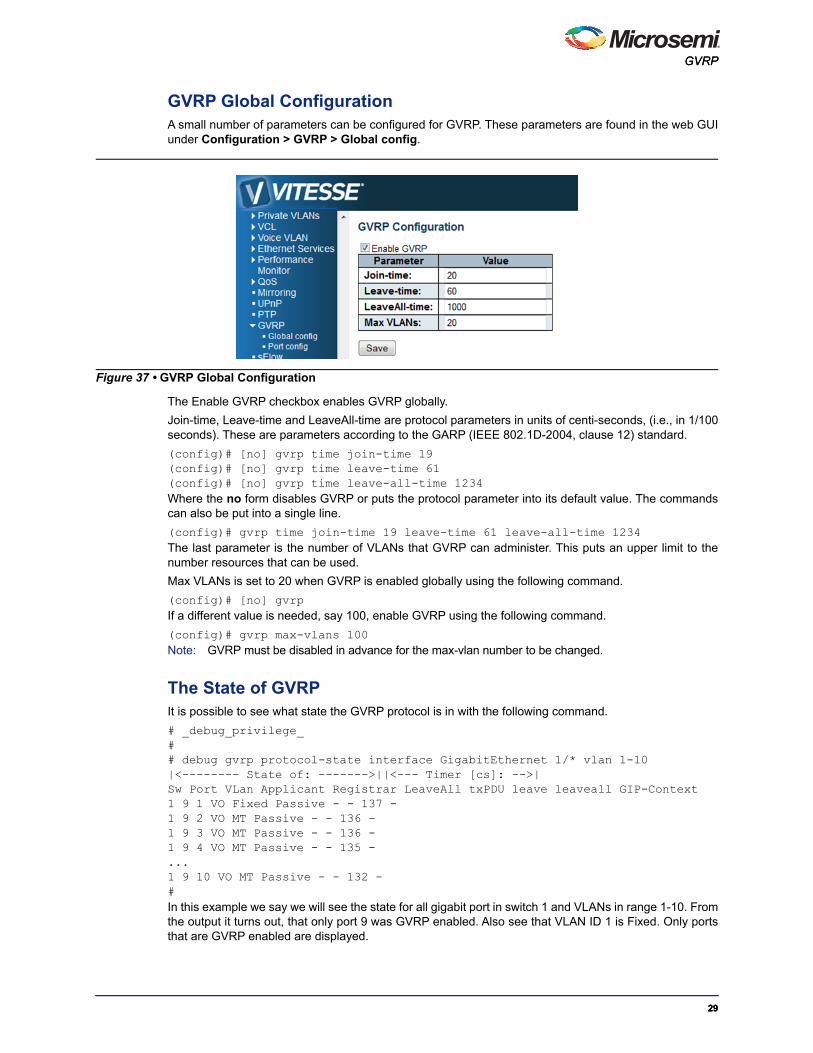
GVRP Global ConfigurationA small number of parameters can be configured for GVRP. These parameters are found in the web GUIunder Configuration > GVRP > Global config.
The Enable GVRP checkbox enables GVRP globally.
Join-time, Leave-time and LeaveAll-time are protocol parameters in units of centi-seconds, (i.e., in 1/100seconds). These are parameters according to the GARP (IEEE 802.1D-2004, clause 12) standard.
(config)# [no] gvrp time join-time 19(config)# [no] gvrp time leave-time 61(config)# [no] gvrp time leave-all-time 1234Where the no form disables GVRP or puts the protocol parameter into its default value. The commandscan also be put into a single line.
(config)# gvrp time join-time 19 leave-time 61 leave-all-time 1234The last parameter is the number of VLANs that GVRP can administer. This puts an upper limit to thenumber resources that can be used.
Max VLANs is set to 20 when GVRP is enabled globally using the following command.
(config)# [no] gvrpIf a different value is needed, say 100, enable GVRP using the following command.
(config)# gvrp max-vlans 100Note: GVRP must be disabled in advance for the max-vlan number to be changed.
The State of GVRPIt is possible to see what state the GVRP protocol is in with the following command.
# _debug_privilege_## debug gvrp protocol-state interface GigabitEthernet 1/* vlan 1-10|<-------- State of: ------->||<--- Timer [cs]: -->|Sw Port VLan Applicant Registrar LeaveAll txPDU leave leaveall GIP-Context1 9 1 VO Fixed Passive - - 137 -1 9 2 VO MT Passive - - 136 -1 9 3 VO MT Passive - - 136 -1 9 4 VO MT Passive - - 135 -...1 9 10 VO MT Passive - - 132 -#In this example we say we will see the state for all gigabit port in switch 1 and VLANs in range 1-10. Fromthe output it turns out, that only port 9 was GVRP enabled. Also see that VLAN ID 1 is Fixed. Only portsthat are GVRP enabled are displayed.
Figure 37 • GVRP Global Configuration
2929

Layer 2 Protocol Configuration Layer 2 Protocol Configuration
All terms like Applicant, Registrar, … , GIP-Context, can be found in the GARP standard.
A dash for a timer means that, that timer is not running. A dash for GIP-Context means that that particularentry is not in a GIP-Context. This will be the case, if the port is down or if it is not in forwarding mode dueto spanning tree.
GIP-Context 0 is Base Spanning Tree Context (IEEE 802.1D-2004, 12.2.4). If MSTP is used, then GIP-Context 1 is MSTI-1, …, GIP-Context 7 is MSTI-7.
Fixed and Forbidden VLANsThe Fixed and Forbidden VLANs are configured from the VLAN menu by going to Configuration >VLANs.
VLAN 1 and 2 are set to Allowed and VLAN 5 to Forbidden. Port 2 has different settings.
Note: In GVRP, Allowed VLANs are called Fixed.
With this configuration, and with port 1, 2 and 3 GVRP enabled, the state of GVRP is as follows.
# debug gvrp protocol-state interface GigabitEthernet 1/* vlan 1-30|<-------- State of: ------->||<--- Timer [cs]: -->|Sw Port VLan Applicant Registrar LeaveAll txPDU leave leaveall GIP-Context1 1 1 VO Fixed Passive - - 895 -1 1 2 VO Fixed Passive - - 894 -1 1 3 VO MT Passive - - 894 -1 1 4 VO MT Passive - - 893 -1 1 5 VO Forbidden Passive - - 893 -1 1 6 VO Forbidden Passive - - 892 -1 1 7 VO Forbidden Passive - - 891 -1 1 8 VO MT Passive - - 891 -. . . . . . . . . .1 1 30 VO MT Passive - - 877 -1 2 1 QA MT Passive - - 140 01 2 2 VO MT Passive - - 139 0. . . . . . . . . .1 2 19 VO MT Passive - - 129 01 2 20 VO Fixed Passive - - 128 01 2 21 VO MT Passive - - 128 0
Figure 38 • VLAN Table
3030

Multiple Spanning Tree ProtocolMultiple Spanning Tree Protocol
1 2 22 VO MT Passive - - 127 01 2 23 VO Fixed Passive - - 126 01 2 24 VO MT Passive - - 126 01 2 25 VO Forbidden Passive - - 125 01 2 26 VO MT Passive - - 124 0. . . . . . . . . .1 2 30 VO MT Passive - - 122 01 3 1 VO Fixed Passive - - 743 01 3 2 VO MT Passive - - 743 0. . . . . . . . . .1 3 30 VO MT Passive - - 726 0#In the Registrar state the Fixed and Forbidden states match what has been set in the VLAN menu.
In this context, we have configured 9 VLAN IDs: 1, 2, 5, 6, 7, 20, 23, and 25. This takes 9 GVRPresources. By default we have 20 GVRP resources. If the Allowed VLANs are set to 1-4095, which isdefault when setting the Mode to Hybrid, and that port is GVRP enabled, then it would require 4096GVRP resources. So in that case, the GVRP should have been started with the following command.
(config)# gvrp max-vlans 4096
Multiple Spanning Tree Protocol
Bridge Settings
ICLI Commands for Basic SettingsThe following ICLI commands refer to the basic settings.
The protocol version is set by the ICLI command:
(config)# spanning-tree mode [mstp|rstp|stp]The bridge priority is set by:
(config)# spanning-tree mst 0 <4096*i, i=0,…,15>where <4096*i, i=0,…,15> is one of the numbers 4096*i, where i=0,…,15.
The forward delay is set by:
(config)# spanning-tree mst forward-time <4-30>
Figure 39 • Bridge Setting
3131

Layer 2 Protocol Configuration Layer 2 Protocol Configuration
Where <4-30> is one of the numbers 4, 5,…,30.
The max age is set by:
(config)# spanning-tree mst max-age <6-40>The max hop is set by:
(config)# spanning-tree mst max-hop <6-40>The transmit hold count is set by:
(config)# spanning-tree transmit hold-count <1-10>
ICLI Commands for Advanced SettingsThe following ICLI commands refer to the advanced settings.
The edge port BPDU filtering is enabled with the ICLI command:
(config)# [no] spanning-tree edge bpdu-filterThe edge port BPDU guard is enabled with the ICLI command:
(config)# [no] spanning-tree edge bpdu-guardThe port error recovery and port error recovery timout is set by one ICLI command:
(config)# [no] spanning-tree recovery interval <30-86400>which both enables and sets the value. The no form disables it.
MSTI ConfigurationBy default, all VLAN Ids are mapped to the Common and Internal Spanning Tree (CIST). If the protocolversion is set to MSTP, then a VLAN ID can be mapped to one out of 8 spanning trees, where CIST isone. The 7 others are called MSTI1,…, MSTI7. A MSTI configuration also has a name and revision. Allthese values have to be identical on the switches in the network. Otherwise the configuration will not takeeffect.
The configuration identity is configured as follows.
(config)# spanning-tree mst name <ConfigurationName> revision <RevisionNumber>
Figure 40 • MSTI Configuration
3232

Multiple Spanning Tree ProtocolMultiple Spanning Tree Protocol
where <ConfigurationName> is a string of maximum length 32 characters, and <RevisionNumber> is aninteger in the range 1,…,65535.
The VLANs are added to MSTI1 and MIST2 with the following commands.
(config)# [no] spanning-tree mst 1 vlan 10-15(config)# [no] spanning-tree mst 2 vlan 16,18The no form deletes all VLANs in the MSTI in question.
MSTI PrioritiesEach MSTI and CIST can be given a priority.
A low priority number indicates higher priority.
A Bridge Identifier is constructed per CIST, MSTI1,…,MSTI7, the bridge priority number. This isconcatenated with the MAC address of the switch. In this way the bridge Identifier is unique.
A low bridge Identifier indicates a higher priority. A high priority means that the switch tends to be the rootof the spanning tree. If two switches have the same bridge priority, then for example, setting MSTI1priority higher, or setting MSTI2 lower, makes one switch tends the root.
Figure 41 • MSTI Priorities
3333

Layer 2 Protocol Configuration Layer 2 Protocol Configuration
STP CIST Port ConfigurationSTP is configured on a port basis in the web GUI at Configuration > Spanning Tree > CIST Ports.
All parameters, except Path Cost and Priority, are specific for the port and not for CIST. These twoparameters can be set for each MSTI, but the other parameters cannot because they apply to the port. If,for example, spanning tree is disabled (as it is for port 3), it applies to the CIST and all the MSTIs.
When using the ICLI, the CIST Aggregation Port Configuration commands are performed at the Configmode prompt as follows.
(config)#The CIST Normal Port Configuration commands are performed in the Config Interface mode prompt asfollows.
(config-if)#The following commands below assume that the user is in the interface config mode.
STP EnabledA port can be individually enabled or disabled for taking part in the spanning tree protocol with thefollowing command.
(config-if)# [no] spanning-tree
Path Cost and PriorityThe path cost and priority are set by the following commands:
(config-if)# spanning-tree mst 0 cost <Cost>(config-if)# spanning-tree mst 0 port-priority <Priority><Cost> is a number in the range 1 to 200000000 or it may be auto. If set to auto, the path cost will be setto some value appropriate for the physical link speed, using IEEE 802.1D recommended values.
<Priority> is a number in the range 0 to 240 and a multiple of 16. If it is not a multiple of 16 then it will beset to 0.
Figure 42 • CIST Port Configuration
3434

Multiple Spanning Tree ProtocolMultiple Spanning Tree Protocol
The path cost is used by STP when selecting ports. Low cost is chosen in favor of high cost. If two portshave the same cost, then priority is used as a tie breaker.
Admin Edge and Auto EdgeThese two features are activated by the following ICLI commands.
(config-if)# [no] spanning-tree edge(config-if)# [no] spanning-tree auto-edgeThe first command changes the field Admin Edge in the web GUI, and the second changes Auto Edge.These two values control how a port is declared to be an edge port or not. An edge port is a port which isnot connected to a bridge.
If auto edge is enabled, then the port determines whether it is an edge port by registering if BPDUs arereceived on that port. The admin edge determines what the port should start as, being edge or not, untilauto edge if enabled, then change.
The decision can be seen by selecting Monitor > Spanning Tree > Bridge Status, then clicking onCIST. Then the Edge field shows the decision.
Restricted Role and Restricted TCNThese two features are activated by the following ICLI commands.
(config-if)# [no] spanning-tree restricted-role(config-if)# [no] spanning-tree restricted-tcnIf restricted role is enabled it causes the port not to be selected as root port for the CIST or any MSTI,even if it has the best spanning tree priority vector. Such a port will be selected as an alternate port afterthe root port has been selected. If set, it can cause lack of spanning tree connectivity. It can be set by anetwork administrator to prevent bridges external to a core region of the network to influence thespanning tree active topology, possibly because those bridges are not under the full control of theadministrator. This feature is also known as Root Guard.
If restricted TCN is enabled it causes the port not to propagate received topology change notificationsand topology changes to other ports. If set, it can cause temporary loss of connectivity after changes in aspanning tree's active topology as a result of persistently incorrect learned station location information. Itis set by a network administrator to prevent bridges external to a core region of the network, causingaddress flushing in that region, possibly because those bridges are not under the full control of theadministrator or the physical link state of the attached LANs transits frequently.
BPDU GuardThis feature is activatd the following ICLI command.
(config-if)# [no] spanning-tree bpdu-guardIf enabled it causes the port to disable itself upon receiving valid BPDU's. Contrary to the similar bridgesetting, the portEdgestatus does not affect this setting.
Point-to-PointThis feature is activated by the following ICLI command.
(config-if)# [no] spanning-tree link-type {auto|point-to-point|shared}where the no form is equivalent to setting it to auto.
Setting the link to point-to-point, shows up in the web GUI as Forced True. Setting it to shared, is
shown as Force False. Setting it to auto shows as Auto.
3535

Layer 2 Protocol Configuration Layer 2 Protocol Configuration
MSTI PortsThe user must select which MSTI configuration to view starting at Configuration > Spanning Tree >MSTI Ports.
Select the desired MSTI and click Get.
The ICLI commands for setting the path cost and priority is the same as for CIST, but with the changethat the MSTI is not 0 (MSTI0 is CIST), but a number from 1 to 7.
(config-if)# spanning-tree mst <MSTI> cost <Cost>(config-if)# spanning-tree mst <MSTI> port-priority <Priority>
Figure 43 • MSTI Port Configuration
Figure 44 • MST1 MSTI Port Configuration
3636

Multiple Spanning Tree ProtocolMultiple Spanning Tree Protocol
Here <MSTI> is the number of the MSTI, from 1 to 7.
The other parameters are the same as in the CIST case.
<Cost> is a number in the range 1 to 200000000 or it may be auto. If set to auto, then the path cost willbe set to some value appropriate for the physical link speed, using IEEE 802.1D recommended values.
<Priority> is a number in the range 0 to 240 and a multiple of 16. Note that if it is not a multiple of 16 thenit will be set to 0.
The path cost is used by STP when selecting ports. Low cost is chosen in favor of high cost. And if twoports have the same cost, then priority is used as a tie breaker.
3737

VPPD-03596. 1.3. July 2015
Microsemi makes no warranty, representation, or guarantee regarding the information contained herein orthe suitability of its products and services for any particular purpose, nor does Microsemi assume anyliability whatsoever arising out of the application or use of any product or circuit. The products soldhereunder and any other products sold by Microsemi have been subject to limited testing and should notbe used in conjunction with mission-critical equipment or applications. Any performance specifications arebelieved to be reliable but are not verified, and Buyer must conduct and complete all performance andother testing of the products, alone and together with, or installed in, any end-products. Buyer shall not relyon any data and performance specifications or parameters provided by Microsemi. It is the Buyer'sresponsibility to independently determine suitability of any products and to test and verify the same. Theinformation provided by Microsemi hereunder is provided “as is, where is” and with all faults, and the entirerisk associated with such information is entirely with the Buyer. Microsemi does not grant, explicitly orimplicitly, to any party any patent rights, licenses, or any other IP rights, whether with regard to suchinformation itself or anything described by such information. Information provided in this document isproprietary to Microsemi, and Microsemi reserves the right to make any changes to the information in thisdocument or to any products and services at any time without notice.
Power Matters.TM
Microsemi Corporation (Nasdaq: MSCC) offers a comprehensive portfolio of semiconductorand system solutions for communications, defense & security, aerospace and industrialmarkets. Products include high-performance and radiation-hardened analog mixed-signalintegrated circuits, FPGAs, SoCs and ASICs; power management products; timing andsynchronization devices and precise time solutions, setting the world's standard for time; voiceprocessing devices; RF solutions; discrete components; security technologies and scalableanti-tamper products; Ethernet solutions; Power-over-Ethernet ICs and midspans; as well ascustom design capabilities and services. Microsemi is headquartered in Aliso Viejo, Calif., andhas approximately 3,600 employees globally. Learn more at www.microsemi.com.
Microsemi Corporate HeadquartersOne Enterprise, Aliso Viejo,CA 92656 USA
Within the USA: +1 (800) 713-4113 Outside the USA: +1 (949) 380-6100Sales: +1 (949) 380-6136Fax: +1 (949) 215-4996E-mail: [email protected]
© 2015 Microsemi Corporation. Allrights reserved. Microsemi and theMicrosemi logo are trademarks ofMicrosemi Corporation. All othertrademarks and service marks are theproperty of their respective owners.