Embed Size (px)
Citation preview

202
Rakenteiden Mekaniikka (Journal of Structural Mechanics) Vol. 49, No 4, 2016, pp. 202-219 rmseura.tkk.fi/rmlehti/ ©The Authors 2016. Open access under CC BY-SA 4.0 license.
Ensuring the ductility and the rotational ability of a fin plate connection
Ilari Pirhonen1, Ville Laine
Summary. This article is based on the author’s master’s thesis [1]. A new method was developed for ensuring the sufficient ductility and rotational ability of fin plate connections. The new method is a suitable supplement or replacement for the method presented in ECCS No 126. Parameters were derived using nonlinear FEM analysis. The recommended design process, that includes the rotational ability, is presented.
Key words: fin plate, ductility, rotational ability, rotational stiffness, bearing
Received 9 September 2016. Accepted 14 December 2016. Published online 30 December 2016.
Introduction
In the global analysis of a steel framed building, fin plate connections are usually assumed to be hinged. When the connection design is considered, the rotational stiffness and moment resistance of the connection become significant and should be taken into account, even though the calculation of the real bolt forces is analytically complicated. The rotational stiffness of the bolt assembly and the bearing member together determine the shape of the actual bending moment curve. In order to avoid premature failure caused by the rotation of the simply supported beam end, the connection should have sufficient ductility and rotational ability. In the design process of a ductile connection it is important to choose the right bolt sizes and material thicknesses so that yielding caused by bearing is possible before the shear failure of the bolts occur.
One Eurocode based design procedure for ensuring the rotation ability and ductility of a fin plate connection is presented in ECCS No 126 [6]. In the design procedure, the bolt assembly is loaded with a pure bending moment and it is checked that the failure mode is of ductile type. When the ductility is based on yielding caused by bearing, it’s
1 Corresponding author [email protected]

203
unclear how great an elongation can be allowed for the bolt hole, when the bearing resistance according to Eurocode is lower than the shear resistance of the bolt. According to recent research (Primoz Može, The University of Ljubljana) [4] Eurocode’s bearing resistance is conservative, which leads to unsafe results when ductility design is considered. The question relates especially to connections with a high bolt assembly, where a small rotation requires great deformation in the bolt holes furthest from the gravity centre of the bolt assembly.
Ductility as a design criteria in steel structures
Ductility describes the material’s ability for deformation between the onset of yielding and actual failure. [2] Usually the numeric value of ductility can be expressed as
𝜇𝜇 =𝑑𝑑𝑑𝑑𝑑𝑑𝑑𝑑𝑑𝑑𝑑𝑑𝑑𝑑𝑑𝑑𝑑𝑑𝑑𝑑𝑑𝑑 𝑑𝑑𝑑𝑑 𝑢𝑢𝑢𝑢𝑑𝑑𝑑𝑑𝑑𝑑𝑑𝑑𝑑𝑑𝑑𝑑 𝑢𝑢𝑑𝑑𝑑𝑑𝑑𝑑𝑑𝑑 𝑠𝑠𝑑𝑑𝑑𝑑𝑑𝑑𝑑𝑑𝑑𝑑𝑑𝑑𝑑𝑑𝑑𝑑𝑑𝑑𝑑𝑑𝑑𝑑𝑑𝑑𝑑𝑑𝑑𝑑𝑑𝑑 𝑑𝑑𝑑𝑑 𝑑𝑑ℎ𝑑𝑑 𝑑𝑑𝑑𝑑𝑠𝑠𝑑𝑑𝑑𝑑 𝑑𝑑𝑑𝑑 𝑦𝑦𝑑𝑑𝑑𝑑𝑢𝑢𝑑𝑑𝑑𝑑𝑑𝑑𝑙𝑙. (1)
The existence of ductility requires that there exists a limit in which the yielding starts, and after reaching it, the material can strain or elongate plastically without losing its strength. The definition is feasible in any level of the structural hierarchy. An example of measuring ductility in some basic levels of the structural hierarchy [3] is presented in Figure 1. The considered measures in each level are presented in Figure 1. At the material level, the ductility means the length of the stress-strain curve after the elastic part.
There are many factors that cause erosion when greater levels of the structural hierarchy are considered [3]. One explanation could be, that the fragility-causing properties of all the lower structural levels are accumulated to the observed level. In order
Figure 1. Examples of the measures of ductility in the levels of the structural hierarchy.

204
to design ductile frames, it is important to consider ductility on the material and When connection levels and design ductile connections with a good rotational ability.
Ductility is considered as a design criteria of connections, the basic idea is to design fragile components to be stronger than ductile components. In the case of the ductility of a fin plate connection, the essential ductile component is yielding caused by bearing. Shear resistance of the bolts should be greater than the bearing resistance. Overstrength in the ductile component may lead to the fragile result as presented in Figure 2. The problem at the material level is that usually only the lowest allowed yield strength is given in the material standards, whereas the upper boundary is unknown. When considering ductility at the connection level, the design rules may lead to a conservative resistance for the ductile component, which in term leads to unsafe results.
Internal forces of a fin plate connection
Fin plate connections have a rotational stiffness S, which depends mostly on the height of the bolt group. The bending moment diagram nearby the connection is presented in Figure 3. The spring stiffness can be derived using the component method with a good accuracy [5]. Calculating the spring stiffness is a nonlinear but also a hyperstatic problem when the number of bolts is more than two.
Figure 2. The effect of overstrength in ductility design [7].
Figure 3. The bending moment diagram [8].
205
In the design process of ECCS No 126 the connection is designed with an imaginary bending moment VEd ∙ z, where z is the distance from the bolt group’s centre of gravity to the column’s flange. Bolt forces caused by the bending moment are calculated using elastic distribution [6]. Shear and axial forces are usually shared by the bolts equally, but in case of a high connection the vertical bolt force components actually correspond to the shear stress distribution of the web.
Ductility and rotational ability of a fin plate connection
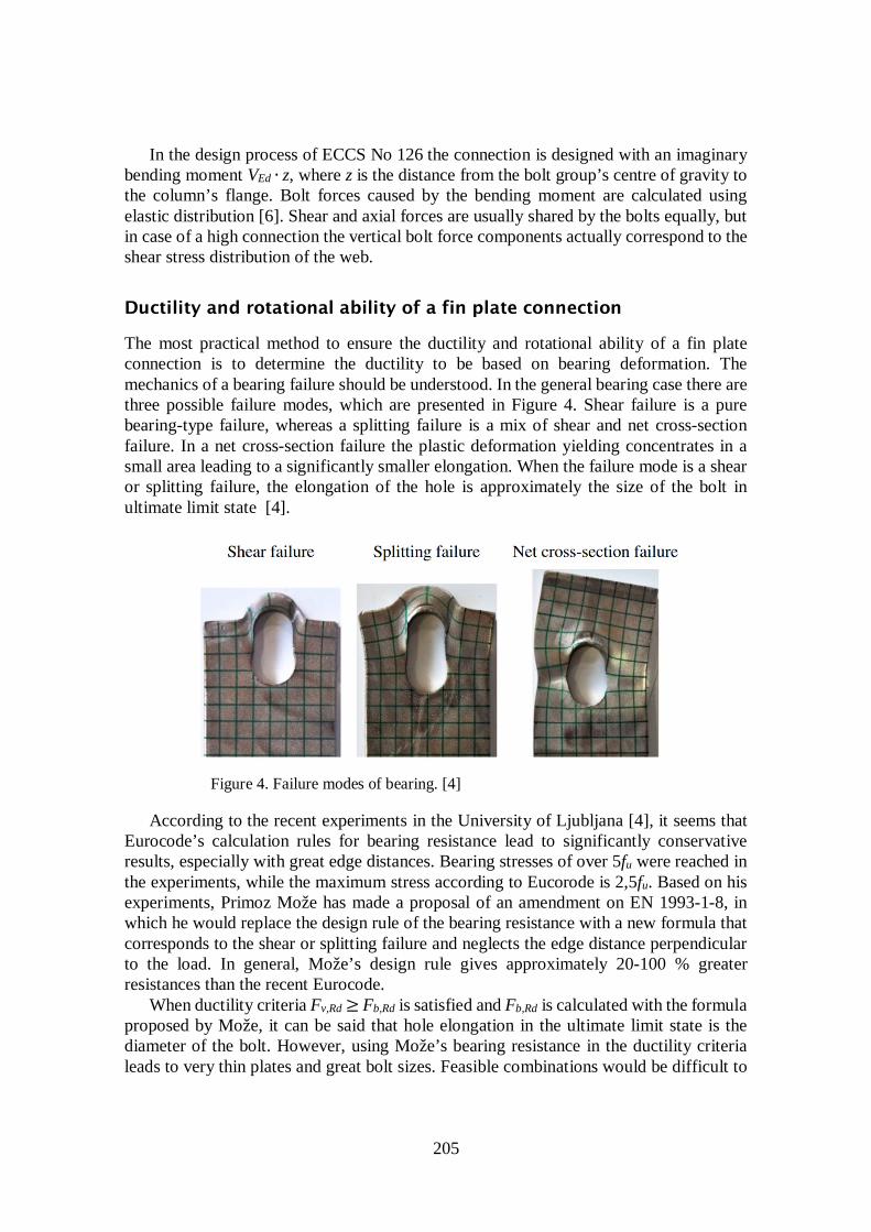
The most practical method to ensure the ductility and rotational ability of a fin plate connection is to determine the ductility to be based on bearing deformation. The mechanics of a bearing failure should be understood. In the general bearing case there are three possible failure modes, which are presented in Figure 4. Shear failure is a pure bearing-type failure, whereas a splitting failure is a mix of shear and net cross-section failure. In a net cross-section failure the plastic deformation yielding concentrates in a small area leading to a significantly smaller elongation. When the failure mode is a shear or splitting failure, the elongation of the hole is approximately the size of the bolt in ultimate limit state [4].
According to the recent experiments in the University of Ljubljana [4], it seems that Eurocode’s calculation rules for bearing resistance lead to significantly conservative results, especially with great edge distances. Bearing stresses of over 5fu were reached in the experiments, while the maximum stress according to Eucorode is 2,5fu. Based on his experiments, Primoz Može has made a proposal of an amendment on EN 1993-1-8, in which he would replace the design rule of the bearing resistance with a new formula that corresponds to the shear or splitting failure and neglects the edge distance perpendicular to the load. In general, Može’s design rule gives approximately 20-100 % greater resistances than the recent Eurocode.
When ductility criteria Fv,Rd ≥ Fb,Rd is satisfied and Fb,Rd is calculated with the formula proposed by Može, it can be said that hole elongation in the ultimate limit state is the diameter of the bolt. However, using Može’s bearing resistance in the ductility criteria leads to very thin plates and great bolt sizes. Feasible combinations would be difficult to
Figure 4. Failure modes of bearing. [4]

206
find in practical cases. In order to avoid ending up with impossible design situations, using recent Eurocode is a better choice. One must know that Eurocode’s bearing resistance is not the turning point of an ideal plastic force-deformation curve and the elongation will be barely visible. According to the FEM experiments presented in this paper, it seems that 0,1d is a safe limit for hole elongation, when Fv,Rd = Fb,Rd and Fb,Rd are calculated according to the recent Eurocode.
In a fin plate connection, the bearing yielding starts at the highest bolt row, where the horizontal bolt force caused by the bending moment is towards the edge. The edge distance, spacing and bolt should be chosen so that the ductility condition Fv,Rd ≥ Fb,hor,Rd, where hor refers to horizontal direction, is satisfied for the highest row. The condition is easier to satisfy in the beam’s web because the material thickness in the web is probably the thinnest.
Design method for rotational capacity
A new design method for calculating the rotational capacity of the bolt group has been developed in the master’s thesis [1]. Before calculating the rotational capacity, a few requirements must be satisfied. First of all, the bolt sizes and edge distance to the web’s vertical edge are chosen so that the bearing resistance of the beam’s web is weaker than the bolt’s shear resistance. The bearing resistance is determined in the horizontal direction assuming the bolt force towards the web’s edge. Secondly, the stability of the fin plate is ensured by choosing the thickness so that the non-dimensional slenderness �̅�𝜆 is not greater than 0,2. The weld size is chosen to correspond to the connection’s full strength. The criteria of full strength can be either the yielding of the plate or the total characteristic shear resistance of the bolts.
The basis of the design method is the utilization rate of the bolt that can be expressed as the square sum of the vertical and horizontal utilization rates. The condition is
��𝐹𝐹𝑣𝑣,𝑣𝑣𝑣𝑣𝑣𝑣,𝐸𝐸𝐸𝐸
𝐹𝐹𝑣𝑣,𝑅𝑅𝐸𝐸�2
+ �𝐹𝐹𝑣𝑣,ℎ𝑜𝑜𝑣𝑣,𝐸𝐸𝐸𝐸
𝐹𝐹𝑣𝑣,𝑅𝑅𝐸𝐸�2
≤ 1. (2)
The vertical bolt force is
𝐹𝐹𝑣𝑣,𝑣𝑣𝑣𝑣𝑣𝑣,𝐸𝐸𝐸𝐸 =𝑉𝑉𝐸𝐸𝐸𝐸𝑑𝑑 , (3)
where n is the number of bolts. The utilization rate of the bolt in the horizontal direction is expressed as the ratio of
the hole’s horizontal deformation caused by loading Δd0,x,Ed and the deformation in the ultimate limit state Δd0,x,Rd when only the horizontal load is considered. The utilization rate of the bolt is
��𝐹𝐹𝑣𝑣,𝑣𝑣𝑣𝑣𝑣𝑣 ,𝐸𝐸𝐸𝐸
𝐹𝐹𝑣𝑣,𝑅𝑅𝐸𝐸�2
+ �𝛥𝛥𝑑𝑑0,𝑥𝑥,𝐸𝐸𝐸𝐸
𝛥𝛥𝑑𝑑0,𝑥𝑥,𝑅𝑅𝐸𝐸�2
≤ 1. (4)
207
The term Δd0,x,Ed is unknown. In the ultimate limit state the utilization rate is set to 1 and Δd0,x,Ed is replaced with the term Δd0,x,max, which means the available horizontal deformation capacity of the hole. The term Δd0,x,max includes the negative influence of the vertical bolt load to the available horizontal deformation. In the ultimate limit state the condition is
��𝐹𝐹𝑣𝑣,𝑣𝑣𝑣𝑣𝑣𝑣,𝐸𝐸𝐸𝐸
𝐹𝐹𝑣𝑣,𝑅𝑅𝐸𝐸�2
+ �𝛥𝛥𝑑𝑑0,𝑥𝑥,𝑚𝑚𝑚𝑚𝑥𝑥
𝛥𝛥𝑑𝑑0,𝑥𝑥,𝑅𝑅𝐸𝐸�2
= 1, (5)
from which can be solved
𝛥𝛥𝑑𝑑0,𝑥𝑥,𝑚𝑚𝑚𝑚𝑥𝑥 = 𝛥𝛥𝑑𝑑0,𝑥𝑥,𝑅𝑅𝐸𝐸��1 − �𝐹𝐹𝑣𝑣,𝑣𝑣𝑣𝑣𝑣𝑣,𝐸𝐸𝐸𝐸
𝐹𝐹𝑣𝑣,𝑅𝑅𝐸𝐸�2
� . (6)
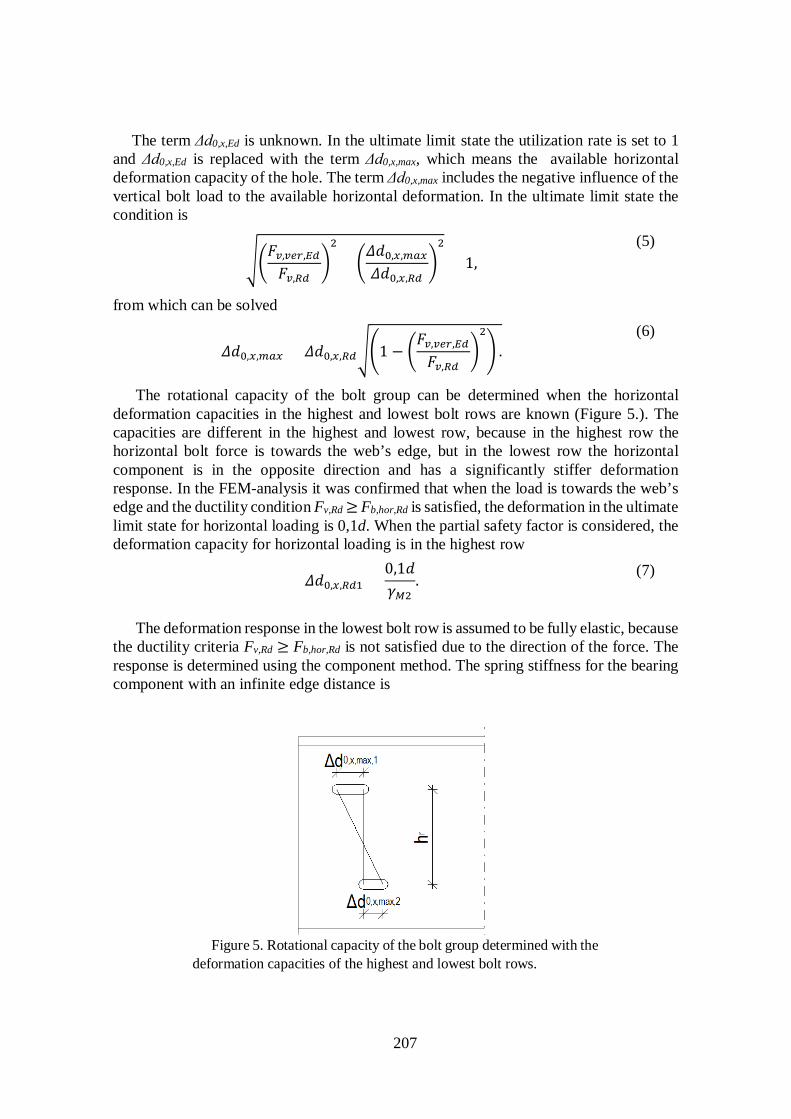
The rotational capacity of the bolt group can be determined when the horizontal deformation capacities in the highest and lowest bolt rows are known (Figure 5.). The capacities are different in the highest and lowest row, because in the highest row the horizontal bolt force is towards the web’s edge, but in the lowest row the horizontal component is in the opposite direction and has a significantly stiffer deformation response. In the FEM-analysis it was confirmed that when the load is towards the web’s edge and the ductility condition Fv,Rd ≥ Fb,hor,Rd is satisfied, the deformation in the ultimate limit state for horizontal loading is 0,1d. When the partial safety factor is considered, the deformation capacity for horizontal loading is in the highest row
𝛥𝛥𝑑𝑑0,𝑥𝑥,𝑅𝑅𝐸𝐸1 =0,1𝑑𝑑𝛾𝛾𝑀𝑀2
. (7)
The deformation response in the lowest bolt row is assumed to be fully elastic, because the ductility criteria Fv,Rd ≥ Fb,hor,Rd is not satisfied due to the direction of the force. The response is determined using the component method. The spring stiffness for the bearing component with an infinite edge distance is
Figure 5. Rotational capacity of the bolt group determined with the deformation capacities of the highest and lowest bolt rows.

208
𝑘𝑘𝑤𝑤 = 30 ∙ 𝑑𝑑𝑑𝑑𝑑𝑑 �1,5𝑑𝑑𝑤𝑤
16 𝑑𝑑𝑑𝑑 ; 2,5� 𝑑𝑑𝑑𝑑𝑢𝑢 . (8)
In the ultimate limit state for the horizontal load, the hole deformations in the lowest bolt row are
𝛥𝛥𝑑𝑑0,𝑥𝑥,𝑅𝑅𝐸𝐸,2 =𝐹𝐹𝑣𝑣,𝑅𝑅𝐸𝐸
𝑘𝑘𝑤𝑤. (9)
The partial safety factor in (9) is included in Fv,Rd. The horizontal deformation capacities in the highest and lowest rows (Δd0,x,max,1 and
Δd0,x,max,2) are calculated separately with the formula (6) using (7) for the highest row and (9) for the lowest row. The rotational capacity of the bolt group is
𝜑𝜑𝑅𝑅𝐸𝐸 =1𝜂𝜂𝑤𝑤
(𝛥𝛥𝑑𝑑0,𝑥𝑥,𝑚𝑚𝑚𝑚𝑥𝑥,1 + 𝛥𝛥𝑑𝑑0,𝑥𝑥,𝑚𝑚𝑚𝑚𝑥𝑥,2)ℎ𝑣𝑣
, (10)
where ηw is the web’s hole deformations’ share of the connection’s total rotation. The share can never be 100 %, because the rotation is always a sum of the deflection of the bolts and the hole deformations in both the fin plate and the web. The term ηw depends on the plate thicknesses, edge distances and bolts sizes and is difficult to determine. The FEM analysis showed that it has a great variation scale somewhere between 50…100 %. According to the FEM study in the master thesis [1] it seems, that a value is 80 % would cover most of the practical design cases. However, using 100 % always a safe choice. A greater value for ηw produces a more conservative rotational capacity. It is also possible to get rid of the term ηw by evaluating the remaining available deformation components with the component method. The dimension hr is the height of the moment delivering part of the bolt group. The height of the bolt group’s moment delivering part is different than the bolt group’s total height, if the rotational ability is improved using slotted holes in the highest and lowest bolt rows.
The connection has adequate rotational ability if the condition 𝜑𝜑𝐸𝐸𝐸𝐸𝜑𝜑𝑅𝑅𝐸𝐸
≤ 1 (11)
is satisfied. The design value of rotation of the beam with ultimate state limit loads 𝜑𝜑Ed can be calculated assuming the connection hinged, which leads to slightly safer results.
The method is applicable also when the normal force NEd exists, with a small modification. When the normal force is included, the utilization rate of the bolt in the ultimate limit state (5) is
��𝑉𝑉𝐸𝐸𝐸𝐸
𝑑𝑑 ∙ 𝐹𝐹𝑣𝑣,𝑅𝑅𝐸𝐸�2
+ �𝛥𝛥𝑑𝑑0,𝑥𝑥,𝑚𝑚𝑚𝑚𝑥𝑥
𝛥𝛥𝑑𝑑0,𝑥𝑥,𝑅𝑅𝐸𝐸+
𝑁𝑁𝐸𝐸𝐸𝐸𝑑𝑑 ∙ 𝐹𝐹𝑣𝑣,𝑅𝑅𝐸𝐸
�2
= 1 (12)
and the available horizontal deformation of the hole (6)
𝛥𝛥𝑑𝑑0,𝑥𝑥,𝑚𝑚𝑚𝑚𝑥𝑥 = 𝛥𝛥𝑑𝑑0,𝑥𝑥,𝑅𝑅𝐸𝐸 ��1− �𝑉𝑉𝐸𝐸𝐸𝐸
𝑑𝑑 ∙ 𝐹𝐹𝑣𝑣,𝑅𝑅𝐸𝐸�2
−𝑁𝑁𝐸𝐸𝐸𝐸
𝑑𝑑 ∙ 𝐹𝐹𝑣𝑣,𝑅𝑅𝐸𝐸�.
(13)

209
Comparing calculations with the nonlinear FEM
The following FEM study is a summary of the full study presented in the master thesis [1]. The purpose of the FEM analysis was to compare the true distribution of the bolt forces to the usual assumptions, but also to find the suitable parameters for the design method of the rotational capacity and to compare the shear resistance of the connection to the results of a calculation sheet, which is mostly based on the design procedure of ECCS No 126. The calculation was executed with Ansys Mechanical R16.1. The basic structural model is presented in Figure 6. In the half beam model the upper flange is supported in the z-direction and the fin plate’s support is fixed. The rotation is locked at the cross-section surface by coupling the nodes in the x-direction. A uniform incrementally increasing load is placed on the upper flange.
At the connection area, an almost ideally plastic material is applied for the fin plate and the beam (yield strength 355 MPa and tangent modulus 0,5 MPa). The bolts and the main part of the beam is modelled with linearly elastic material E = 210 GPa (Figure 7). A thick meshing is used at the connection area so that there’s at least two elements through the plate thickness. Applied element type is a 20-node quadratic hexahedron. Meshing details are presented in Figure 7.
Figure 6. Basic structural model.

210
The applied connection type between the bolts and the web or the fin plate, and between the fin plate and the web is a frictional contact with the frictional coefficient of 0,01. Bolt forces are measured from the contact forces so that the shear force of the bolt is the contact force of the inner surface of the web’s hole and that the tension is the contact force between the nut and web. The beam parts with different size of meshing were joined with bonded-type of contacts using multipoint constraint equations.
FEM: IPE400 4M24 connection
The first model, presented in Figure 6 and , is an IPE400 connection with 4M24 8.8 bolts. The fin plate thickness of 15 mm is chosen so that the buckling of the plate is not possible. The edge distance from the bolt column to the web’s vertical edge is 1,98d0, which corresponds the limit where Fv,Rd = Fb,hor,Rd. The characteristic value of the shear resistance of the connection according to a calculation sheet is 393 kN. The calculation sheet has been programmed by the corresponding author and it follows mostly the design process of ECCS No 126. According to the calculation sheet, the connection is ductile and fulfills the criteria of ECCS No 126 to avoid premature failure.
Shear and tensile forces of the bolts are presented in Figure 8 and Figure 9 and the utilization rates in Figure 10. The bolts are numbered from top to bottom in an ascending order. If only the shear forces are considered, the connection seems very ductile and none of the bolts reaches the characteristic shear resistance according to EN 1993-1-8. However, the connection being single lapped causes the length axis of the bolt to turn out of the horizontal plane. This phenomenon with more or less constrained flexural deformations of the bolts causes significant contact forces between the nuts and the fin plate or web.
Figure 7. Details of the meshing and the applied material models.

211
Figure 8. Tensile forces of the bolts of an IPE400 4M24 connection.
Figure 9. Shear forces of the bolts of an IPE400 4M24 connection.

212
The tensile force, as well as the shear force, is the greatest at the lowest bolt, where the utilization rate reaches 1 when the connection’s shear force is 375 kN. Even though the connection should be ductile regarding to bearing, the failure mode of the connection seems to be the failure of the lowest bolt with 5 % lower shear load compared to the calculation sheet. The highest hole in the web has the greatest deformation. When the connection’s shear force is 375 kN, the total elongation is 0,06d0, where the horizontal component is 0,04d0. The share of the web’s hole deformations of the connection’s total rotation was 74 %.
To determine the maximum deformation of the web’s holes in the horizontal direction with no vertical shear force, the structural model was modified as presented in Figure 11. Middle bolts were removed and the half beam was shortened. The calculation process was displacement-controlled. An incrementally increasing displacement with from 0 to 15 mm was set on the cross-section surface the positive x-direction, when the connection became subjected to tension. It was determined, that when the utilization rate of the bolt reached 100 %, the deformation of the hole was 0,1d. The hole deformation for a compressed connection was determined by turning the direction of the displacement on the cross-section surface. The result was 0,033d, which is very close to the value 0,03d that can be derived with the component method (8).
Figure 10. Bolt utilization rates for the shear and tension of IPE400 4M24 connection (EN 1993-1-8).

213
The effect of inadequate ductility design was demonstrated by modifying the basic model in Figure 6. In the first modification the thickness of the web was increased by 25 % and in the second one an overstrength of 25 % was applied for the web (yield strength 444 MPa). Thickening the web or increasing the yield strength didn’t have a significant effect on the tensile forces of the bolts, but both modifications raised the top value of the bolt’s shear force by 25 % (Figure 12). The consequence was that in the lowest bolt a 100 % utilization rate was reached with a 25 % smaller connection shear load. The result shows, that overstrength in the material is a real and significant problem in ductility design.
Figure 12. Shear force in the lowest bolt when the web’s thickness or the yield strength of the original model was increased by 25 %.
Figure 11. The modified model to determine the maximum horizontal deformations of the web’s holes.

214
FEM: Welded profile 12M30
The goal in the second calculation case was to determine the same parameters as in the first case, but also to study the special behavior of a high connection and the effect of two bolt columns. The height of the welded beam section is 1300 mm and the bolt group’s height is 1000 mm. Again, buckling of the fin plate is excluded with the adequate thickness of 30 mm and the edge distance from the bolts to the vertical edge of the web, and the horizontal spacing are chosen so that they correspond to the ductility limit where Fv,Rd = Fb,hor,Rd. The edge distance is now 1,77d0 and the horizontal spacing 2,52d0. The structural model is presented in Figure 13. The top flange is now line-supported in the z-direction because of the sensibility for lateral torsional buckling. The shear force resistance of the connection is 3353 kN.
Bolt shear forces in the highest and lowest bolt row are presented in Figure 14. Also, in this case, the lowest row is the most critical. It can also be seen, that the bolt in the inner column always has a slightly greater force than the one in the outer column. This can be explained with the connection’s bending moment. Unlike in the case of a single bolt column, with several bolt columns the bending moment also creates small vertical shear force components in bolts. In the inner bolt column the direction of the vertical components is the same as the direction of the vertical components caused by the pure shear load. In the outer column the vertical components caused by the bending moment are in the opposite direction and they reduce the effect of the pure shear load. Another reason why the inner column has greater bolt shear forces is that it has a stiffer bearing deformation response than the outer column. When tensile forces are also considered, bolt 12 reaches a 100 % utilization rate with the shear load of 2100 kN, which is 37 % less than the resistance determined with the calculation sheet. The web’s share of the total rotation was only 50 %, when bolt 12 failed.
Figure 13. Structural model and bolt numbering of the welded profile.

215
The vertical shear force components in the highest and lowest row and middle area of the connection are presented in Figure 15. The thick linear curve describes the average vertical component, which is the shear load of the connection divided by the number of bolts. When a 100 % utilization rate of bolt 12 was reached, the shear force in bolt 10 was 43 % greater than the average. The vertical components in the highest and the lowest row are clearly under the average curve. Figure 15 proves that the vertical bolt force
Figure 15. Vertical shear force components of the bolts
Figure 14. Bolt shear forces in the highest and the lowest row.

216
distribution follows the paraboilic shear stress distribution of the beam cross-section. Considering that the the maximum shear stress value in the elastic shear stress parabel is 1,5 times the avegage shear stress, the theoretical maximum vertical bolt force would be 1,5 times the average vertical bolt force, when the small effect of the bending moment is neglegted. When the plastic bearing response in the vertical direction is reached, the vertical bolt forces start approaching the average curve, however, the bolts will fail before that.
The greatest possible bearing deformation in the horizontal direction was determined with a similar method as with the IPE400 connection. The modified model is presented in Figure 16. The middle bolt rows were removed. The fin plate and cross-section were lowered from the middle. When the connection was subjected to tension, the inner bolt reached a 100 % utilization rate first with a bearing deformation of 0,09d. In the compressed case the inner row was also the most critical and the deformation that corresponded to the bolt failure was 0,04d.
The recommended design process
The rotational ability of a fin plate connection should always be checked when the beam is connected to the column’s flange, but also in beam-beam connections if
• the primary beam is a box cross-section • secondary beams are on both sides of the primary beam • the torsional span of the primary beam is short • the torsional rotation of the primary beam is prevented for any other reason
Recommended design procedure, where checking the rotational ability is included:
Figure 16. The model that was used to determine the greatest possible horizontal bearing deformations.
217
1. The hinge is placed at the center of the bolt group in the global FEM analysis model. Required input data from the global analysis model for the connection design are shear force VEd, axial force NEd and the connection’s rotation 𝜑𝜑Ed.
2. The bolt sizes, the edge distances and the spacings are chosen so that the ductility criteria in the horizontal direction Fv,Rd ≥ Fb,hor,Rd is satisfied in the web.
3. The stability of the fin plate is ensured by choosing thickness so that the non-dimensional slenderness is not more than 0,2. Recommended buckling length for the fin plate is
• Lcr = L, if the beam is supported horizontally in the direction transverse to the beam’s axis. Dimension L is the distance from the nearest bolt column to the supporting column’s flange
• Lcr = 2 ∙ L otherwise 4. The weld size is chosen to correspond to the full strength of the connection. The
criteria of full strength can be either the yielding of the plate or the total characteristic shear resistance of the bolts.
5. It is checked, that the condition Fv,Rd ≥ 1,5 ∙ VEd / n is satisfied. 6. The connection’s resistance against failure modes is checked for example by using
the design procedure presented in ECCS No 126. The connection is loaded with the imaginary bending moment VEd ∙ z, and an axial load NEd is considered.
7. The rotational capacity is checked with the method presented in this article using the parameters
• Δd0,x,Rd,1 = 0,1d / γM2 • Δd0,x,Rd,2 according to the component method • ηw = 80 %
8. Clause 3 may lead to an unnecessarily thick fin plate if the connection’s eccentricity is great. Clause 3 can be neglected if the ductility is ensured additionally according to the method of ECCS No 126, because the method includes the buckling’s influence on the ductility.
9. Process ends if all the previous clauses are completed. 10. If the rotational ability is inadequate, it can be improved with the following
actions: • Minimizing the height of the bolt group. • Using slotted holes in the highest and lowest bolt rows. It is recommended
to place the slotted holes in the fin plate. The design process returns back to clause 6. If there are no normal sized holes in at least two of the rows, the connection is designed without a bending moment.
• Using oversized holes in every hole of the fin plate or the web. It is recommended to place the oversized holes in the fin plate. The design process returns back to clause 6 and the connection is designed without a bending moment.
In case of a beam-beam connection, where the primary beam is an open cross-section
and has an adequate ability for torsional rotation, the hinge is placed in the centre line of the primary beam. The design process follows for example the principles of ECCS No 126 or SBI Publikation 188. The bolt group is designed for the eccentricity moment

218
VEd ∙ z, where z is the distance of primary beam’s centre line and the bolt group’s centre of gravity.
Washers are recommended to be used on the both sides of the connection.
Conclusions
A new design method for evaluating the rotational ability of a fin plate connection was presented in this article. The parameters were confirmed with a nonlinear FEM analysis. The rotatinal ability derived with the design method was compared to the FEM results in the master thesis [1]. If the exact parameters are available, it seems that the accuracy of the method is ± 10 %. The result depends strongly on the term ηw. The value 80 % will lead to conservative result in most practical design cases, but it’s also possible to get rid of the term ηw by evaluating the remaining available deformation components (bolts in shear and fin plate in bearing) with the component method.
The method is not confirmed with loading experiments, which would be a necessary topic for further study. Some load experiments for fin plate connecctions have already been made by R. Richard [8]. The R. Richard’s load data has already been utilized in the article “Fin plate joint using component method” [5] and could be usefull also for the study of the rotational ability. Despite the load experiment comparison is missing, it is recommended to take the design method immediately into practice and replace or suplement the method in ECCS 126 [6], which was proved inadequate in the master thesis [1].
In this article the design method was derived for a single lapped case, but it’s also applicable for two lapped connection, where the fin plates are on the both sides of the web. In the two lapped case deformation limit Δd0,x,Rd,1 = 0,1d / γM2 is conservative. The two lapped connection is concentric, which will significantly reduces the tensile forces of the bolts. For a two lapped case it’s also easier to satisfy the ductility criteria Fv,Rd ≥ Fb,hor,Rd, since the bolts have double shear capacity compared to the single lapped case. Defining the term Δd0,x,Rd,1 for a two lapped connection would be a necessary topic for further study.
References
[1]
I. Pirhonen, Ensuring the ductility and rotational ability of a fin plate connection, Master’s thesis, Tampere University of Technology, (2016)
[2] http://www.steelconstruction.info/Steel_material_properties (8.3.2016)
[3] V. Gioncu, Framed structures. Ductility and seismic response. General Report, Journal of Constructional Steel Research 55(1-3): 125–154, 2000. doi: 10.1016/S0143-974X(99)00081-4
219
[4] P. Može, Deformation capacity, stiffness and bearing strength at bolt holes, Eighth International Workshop on Connections in Steel Structures, Boston, (2016), 10 p.
[5]
K. Bzdawka, M. Heinisuo, Finplate joint using component method of EN 1993-1-8, Rakenteden mekaniikka 43(1): 25-43, 2010. http://rmseura.tkk.fi/rmlehti/2010/nro1/RakMek_43_1_2010_3.pdf
[6] ECCS, Nº 126: European recommendations for simple joints in steel structures, European Convention for Constructional Steelwork, (2009), 89 s.
[7] N. Hoffmann, L. Rölle, U. Kuhlman, Robustness for Large Steel-Concrete Composite Structures, IABSE Workshop Helsinki, (2013), Safety, Failures and Robustness of Large Structures report, s. 112-119
[8] R. Richard, P. Gillet, J. Kriegh, B. Lewis, The analysis and design of single plate framing connections, Engineering Journal, AISC, 17: 38-52, 1980.
Ilari Pirhonen, Ville Laine A-Insinöörit Suunnittelu Oy Satakunnankatu 23 A FI-33210 Tampere, Finland [email protected], [email protected]