Embed Size (px)
Citation preview
Enhancing the Vertical Mobility of a Robot Hexapod Using Microspines
Matt Martone∗1, Catherine Pavlov∗2, Adam Zeloof2, Vivaan Bahl3, and Aaron M. Johnson2
Abstract— Modern climbing robots have risen to greatheights, but mechanisms meant to scale cliffs often locomoteslowly and over-cautiously on level ground. Here we introduceT-RHex, an iteration on the classic cockroach-inspired hexapodthat has been augmented with microspine feet for climbing. T-RHex is a mechanically intelligent platform capable of efficientlocomotion on ground with added climbing abilities. The legsintegrate the compliance required for the microspines withthe compliance required for locomotion in order to simplifythe design and reduce mass. The microspine fabrication issimplified by embedding the spines during an additive manufac-turing process. We present results that show that the additionof microspines to the T-RHex platform greatly increases themaximum slope that the robot is able to statically hang on (upto a 45◦ overhang) and ascend (up to 55◦) without sacrificingground mobility.
I. INTRODUCTION
In nature, animals have adapted a wide variety of ap-proaches to climbing, but even with finely-tuned sensorimo-tor cortices most can’t measure up to the reliability of insects.Cockroaches are able to scale nearly any natural materialusing microscopic hairs along their legs and feet for surfaceadhesion [1–3]. These hairs catch on surface irregularities,known as asperities, and can support the insect’s bodythrough load sharing across many hairs. The cockroach’sscant cognitive intelligence severely limits its ability to planactions or move dexterously; rather it relies on mechanicalintelligence for locomotion. This approach is promising forfield robots that need to reliably climb on an array of surfacematerials and geometries.
Microspine technology can effectively mimic the adhesionof a cockroach’s foot on a larger scale [4], though heavilydirectional without the aid of Van der Waals forces (as usedin gecko-like adhesives [5]). Microspine grippers can attachto rough surfaces by distributing the load across hundreds ofmillimeter scale hooks sprung with hierarchical compliance.Legged robots such as RiSE [6], Spinybot [7], and LEMUR[8] have demonstrated the effectiveness of microspines forrobotic rock climbing. However, while these systems canscale walls efficiently, their microspine feet and slow jointslimit mobility on flat ground.
Microspines have been utilized to achieve climbing withnumerous morphologies, though all must make design com-
∗M. M. is supported by a DOE Traineeship in Robotics. C. P. is supportedby a NASA Space Technology Research Fellowship. Both contributedequally to the work presented here.
1Robotics Institute, Carnegie Mellon University, Pittsburgh, PA, [email protected]
2Mechanical Engineering, Carnegie Mellon University, Pittsburgh, PA,USA {cpavlov,azz,amj1}@andrew.cmu.edu
3Electrical & Computer Engineering, Carnegie Mellon University, Pitts-burgh, PA, USA [email protected]
Fig. 1. The new T-RHex robot platform statically clinging to roughaggregate concrete. Each leg includes 9 individually compliant microspines.
promises in order to climb. Some like Spinybot [4] aredesigned to only work in scansorial locomotion. LEMUR3is a quadruped which uses active microspine grippers on itsfeet to achieve mobility on vertical and overhung naturalrock surfaces, but requires carefully planned foot placementfor each step that limits travel speed [8,9]. DROP [10] andTBot [11] are small, lightweight wheeled platforms capableof both vertical and level ground mobility, but microspineadhesion quickly degrades as the tips dull on flat ground.RiSE [6] is a hexapedal robot with microspine feet capableof 0.25 m/s locomotion on flat ground, but uses different feetfor walking and climbing.
RHex is a cockroach-inspired ground robot that uses sixlegs to traverse uneven terrain [12–14]. Its curved leg shapeand compliance are key to simplifying control architecturethrough mechanical intelligence [15,16], and it can moveeffectively on a wide array of structured and unstructuredterrains [17–20]. RHex can carry a relatively large payloaddue to the structure of the legs [21], enabling it to carrymany sensors for search and rescue, reconnaissance, or en-vironmental monitoring missions [22]. While quite mobile onhorizontal terrain, the platform’s utility and viability wouldbe improved greatly by adding the ability to scale slopes andwalls. This is especially important in areas with incompleteinfrastructure such as disaster zones or construction sites.
In this paper we present a new leg design (in Sec. II-A) that uses microspines to enable a RHex-like robot tohang onto vertical or even overhanging surfaces, such as thevertical wall in Fig. 1, as well as climb inclined surfacesup to 55◦. The microspine toes, Sec. II-B, are built usingadditive manufacturing to simplify the fabrication process.
arX
iv:1
906.
0481
1v2
[cs
.RO
] 1
9 Se
p 20
19

We leverage the existing leg compliance to avoid the needfor multiple smaller flexures to enable successful adhesion(Sec. II-C). By orienting the spines backwards, we ensurethat the existing RHex forward gaits are unimpeded whiletaking advantage of the microspines for climbing with thetypically unused backward walking gait space (Sec. III). Wetest, in Sec. IV, the new leg design’s ability to climb andhang on a variety of inclined surfaces while maintaininggood level-ground mobility. Finally, we conclude the paperin Sec. V by considering a pathway towards full horizontaland vertical mobility with the platform.
II. MECHANICAL DESIGN
The robot described in this paper is an implementation ofthe standard RHex configuration named “T-RHex,” shown inFig. 1. Like RHex, T-RHex is a hexapedal robot with sixsingle degree-of-freedom compliant semicircular legs. Eachleg is actuated by a Dynamixel MX-64 servo motor capableof continuous 360◦ rotation. Unlike the standard RHexplatform, the legs are comprised of multiple independentlysprung microspine flexures, whose design is discussed in therest of this section. The fully assembled T-RHex platformweighs 2.5kg and measures 254mm between front and backlegs.
In addition to the new legs, T-RHex is equipped with a“climbing tail”. The tail is mounted to what is the frontof the robot during regular walking, which becomes therear of the robot during climbing. Past tails on RHex havebeen primarily oriented upwards and towards the rear (whilewalking) [23], and work by using inertial reorientation. Thetail on T-RHex is lightweight and intended to contact thesurface in order to increase the adhesion forces a the fronttoes, as with the tail in other climbing robots [11,24,25]. Thetail is actuated with a Dynamixel MX-106 servo motor andcan rotate 180◦.
A. Leg Design
RHex’s legs were redesigned to enable T-RHex to climb onhigh-angle terrain. While climbing, T-RHex faces backwards,such that the tips of its appendages are the only points incontact with the surface (an orientation used by some otherlegged robots with semicircular leg designs [26]). A T-RHexleg consists of multiple stacked, thin slices, as seen in Fig. 2.Each individual leg slice, Fig. 3, has a single microspine, andthe stacked slices are able to deflect in plane independentlyof each other, with their shared attachment point concentricwith the driving servo horn. The thickness of the slices wasdetermined by microspine size, as each slice had to fullyenclose its microspine leaving only the tip exposed.
Because the microspines protrude only from the tip of eachleg, they do not interfere with the ground during normalforward walking. This means that ground mobility is notimpacted, as evaluated in Sec. IV-D, and the robot can travelat the same speed regardless of whether the legs containspines or not. This is also useful to prevent surface harmwhile the robot walks, and to protect the spines from dullingwhen not in use.
Fig. 2. A fully assembled T-RHex forked wheel leg (top) and a closeup ofthe microspines on the toes (bottom). Both images show a variety of spineangles, denoted by the color on the end of each leg slice.
B. Microspine Design
Most prior microspine assemblies were fabricated througha multistep additive and subtractive process of polymer cast-ing, milling, and spine embedding called shape depositionmanufacturing (SDM) [27–29]. Here, we take a differentapproach that uses 3D printing to simplify the fabricationprocess. Each microspine is attached to the leg slice with a3D printed PLA piece. These slice “toes” were 3D printed inlarge batches, and paused mid-print to insert the microspines,which were then printed over. Three different spine angles (φin Fig. 3) were fabricated: 60◦, 90◦, and 120◦. Each spineangle allows for adhesion in a different range of the leg’srotation, and as such each leg has a mix of spine angles.Unlike prior legged microspine climbers, which keep theangle of attack of the microspines very constant while instance, T-RHex must maintain adhesion over a large angularrange, making this mix of toe angles key to the success ofthe climbing gait.
The microspines on T-RHex consist of size 12 plain shankfish hooks cut to length. At approximately 0.6mm thick, these

Fig. 3. Drawing of a single microspine flexure. On T-RHex, D is 100mm,W is 10 mm, and φ is 60◦, 90◦, or 120◦. A full leg contains nine stackedmicrospine flexures.
hooks are small enough to allow for 1.5mm thick leg slices.These hooks were chosen for their thickness after preliminaryexperimentation revealed no discernible effect of hook sizeon adhesion within the considered group.
C. Flexure Design
Unlike prior microspine systems, which use SDM withmultiple materials to tune the compliance of the flexures,we have simplified the design to use a monolithic flexureper spine that meets our compliance needs and is easy toreproduce quickly. This is similar to the method used by theAsteroid Redirect Mission Gripper 2.0 [30], but improvesthe repeatability of inserting the spine at the desired angle.The main portion of each leg slice is constructed of lasercuthigh-impact acrylic, which is attached to the 3D printed tipwith acrylic adhesive on a mechanically interlocking shape(Fig. 3).
For effective climbing, the microspines must be able toindependently translate while maintaining a fixed angle,due to the narrow range of attack angles for adhesion ofmicrospines. The geometry of the leg slice flexure allows themicrospine at the tip to deflect on the order of millimetersboth parallel and perpendicular to the climbing surface withminimal rotation of the spine. A full leg stack of flexures hasa spring constant of 4-5 kN/m, compared to a typical springconstant of 0.9 kN/m on comparably sized RHex legs.
D. Cassette Design
The full assembly of each leg is a cassette of nine stackedleg slices and rigid outer plates with thin spacers separatingeach slice to allow independent movement. The rigid outerwalls, shown in black in Fig. 2 (top), prevent out-of-planebending by the leg slices but do not come into contactwith the surface during walking or climbing. As the legsare spaced slightly farther than one leg length apart, thecentral legs are spaced outward with standoffs to preventinterference. Each leg is directly bolted to its servo horn.
III. GAIT DESIGN
A new gait, termed the “inchworm,” was developed forwall climbing to accommodate the mode of action of the
Fig. 4. The “inchworm” climbing gait in action on a 55◦ slope showing thethree pairs of legs moving symmetrically. In this frame the front legs (right)are holding position until the back legs (left) complete a clockwise rotation,and the tail counteracts the tipping torque generated by the microspinepreload force.
microspines. This gait is most similar to the metachronal gaitused to climb stairs [17] where pairs of legs move togetherto propel the robot upwards. Step angles were chosen tomaximize the preload force to set the spines as the adhesionforce of microspines in shear is roughly proportional topreload force normal to the surface.
A metachronal gait also provides symmetric supportingforces on the left and right sides to avoid producing anet torque about any foot. Asymmetric gaits, such as abackwards alternating tripod, failed quickly because themicrospines cannot resist torque in the plane of the wall.
During the “inchworm” gait the back legs provide propul-sion, the front legs engage to hold position between steps,and the tail prevents the back legs from catching or leverag-ing the body off of the wall while recirculating. The centralleg pair is not utilized in the gait variation used to generatethe results below, but can duplicate the role of the front legson steeper surfaces. Shown in Fig. 4 is a still frame of T-RHex executing this gait. In the frame, the back legs (left) arebeginning to recirculate, while the front legs (right) engageto prevent the robot from sliding back down. The tail allowsthe back legs to rotate freely without contacting the surface.
This gait requires some tuning for different slope anglesand surfaces. For instance, steeper angle climbs rely muchmore heavily on the balance of the tail than shallower anglesdo. Vertical ascents, however, suffer from “vaulting,” wherethe robot attempts to adhere the front toes onto the surface,but instead pushes the robot away from the wall, disengagingthe back toes and causing a fall.
IV. EXPERIMENTAL RESULTS
Testing was largely performed on three surface types,chosen to be representative of the various terrains that a smalllegged robotic platform might encounter during deploymentin an urban environment. The robot’s climbing ability wastested extensively on cork board, brick facade, and plywood.

These surfaces were selected as a minimum subset of sur-faces needed to characterize microspine performance on ageneralized exploration scenario.
The three surface choices represent the three most com-mon failure modes of microspine climbing feet, as describedin [31]. Cork board serves as a soft, pseudo-granular materialthat microspines can easily puncture and tear through. Theexpected failure mode is surface degradation due to overload-ing spines. Plywood is a fairly smooth surface on which mi-crospines must rely equally on existing asperities and activesurface deformation by digging into the medium-hardnesswood. The failure mode is a lack of strong adhesion pointsthat prevents the microspines from finding purchase. Brickfacade serves as a hard, pitted surface that is nearly ideal formicrospines to catch strong, favorably-formed asperities. Thefailure mode of brick facade is likely tine fracture or plasticdeformation of the fish hook when feet do not successfullydisengage from unusually strong footholds. Fig. 4 and 6 showthe cork board and Fig. 5 shows the brick test surfaces usedin experiments.
A. Static Slope Cling
The first suite of tests were designed to determine theeffectiveness of the T-RHex leg and microspine designwithout conflating the effects of the climbing gait controller.The leg angle, spine content, and surface material werevaried independently while determining the maximum angleat which the robot could statically cling to the wall. The testprocedure is as follows:
1) Set the position of all the robot’s legs to a givenangle and command the motors to hold that positionindefinitely.
2) Place the robot at a randomly selected position on thesurface while the surface is held horizontal. The robotmust be oriented such that the front while climbing isangled towards the highest point on the surface whenraised.
3) Rotate the test wall about the bottom edge at a rateof approximately 1 degree per second. This rate issufficiently quasi-static such that inertial effects ofmotion can be ignored.
4) Carefully observe the robot while clinging to noteunusual behaviors, interesting microspine adhesionproperties, instances of slip-catch motion, and signsof leg damage.
5) Continue pitching the test wall until the microspinesfail and the robot falls. Note the angle of the wallwhen catastrophic detachment occurs.
The data, listed in Table I and Fig. 7, was collected acrossthree test surfaces and two leg angles with a sample size offive tests each. As a control, the tests using cassettes of mixedangle microspines were compared to a set of tests usingblank legs fabricated as tines without embedded microspines.All statistical comparisons discussed below use a one-tailed,heteroscedastic, t-test.
The data indicates that a shallower leg angle of −120◦
consistently outperformed a steeper leg angle of −150◦ on
Fig. 5. T-RHex hanging from brick facade with a steep overhang. Themaximum static cling angle recorded during experiments was 116◦ andreached a further 135◦ when placed by hand.
TABLE IMAXIMUM STATIC CLING ANGLE DATA
Tail Leg Type Surface θleg (◦) µ (◦) σ (◦)
No Tail
Microspine
Plywood -150 36.2 1.10-120 58 2.12
Cork Board -150 52 3.61-120 79.2 3.77
Brick -150 52.6 10.90-120 73.8 18.24
Blank
Plywood -150 32.2 3.11-120 25.8 2.86
Cork Board -150 34.6 0.55-120 40 2.12
Brick -150 33.6 1.52-120 42 5.70
Tail
Microspine
Plywood -150 57.2 4.60-120 62.4 7.50
Cork Board -150 60.4 2.70-120 66.4 3.44
Brick -150 69.8 21.79-120 92 16.31
Blank
Plywood -150 27.4 3.21-120 20.8 1.79
Cork Board -150 46.6 0.55-120 40.4 0.89
Brick -150 57.2 6.42-120 43.4 12.38
the microspine legs (p < 0.001), which informed the gaitdesign discussed in Sec. III. Performance was similar be-tween cork board and brick, with plywood underperformingby a margin of about 15◦. However, unlike cork boardand plywood, which had tightly clustered data points, theperformance on brick, a heterogeneous surface, was highlydependent on initial robot placement, leading to a muchhigher standard deviation. This is likely due to the variabilityof asperity quality between brick face and brick edges.Furthermore, the data shows that the spines significantlyimproved performance of T-RHex over blank legs for themaximum static cling angle (p < 0.001). This trend can beseen in Fig. 7.
The failure mode of cling was consistently not in the
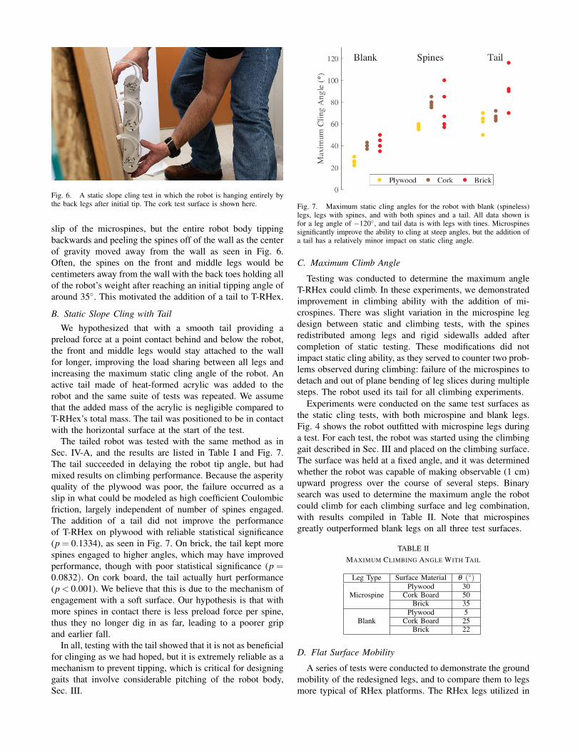
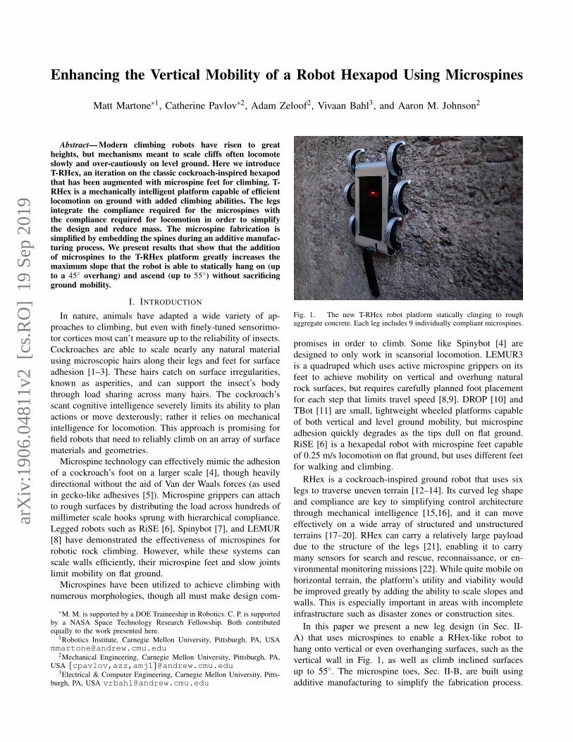
Fig. 6. A static slope cling test in which the robot is hanging entirely bythe back legs after initial tip. The cork test surface is shown here.
slip of the microspines, but the entire robot body tippingbackwards and peeling the spines off of the wall as the centerof gravity moved away from the wall as seen in Fig. 6.Often, the spines on the front and middle legs would becentimeters away from the wall with the back toes holding allof the robot’s weight after reaching an initial tipping angle ofaround 35◦. This motivated the addition of a tail to T-RHex.
B. Static Slope Cling with Tail
We hypothesized that with a smooth tail providing apreload force at a point contact behind and below the robot,the front and middle legs would stay attached to the wallfor longer, improving the load sharing between all legs andincreasing the maximum static cling angle of the robot. Anactive tail made of heat-formed acrylic was added to therobot and the same suite of tests was repeated. We assumethat the added mass of the acrylic is negligible compared toT-RHex’s total mass. The tail was positioned to be in contactwith the horizontal surface at the start of the test.
The tailed robot was tested with the same method as inSec. IV-A, and the results are listed in Table I and Fig. 7.The tail succeeded in delaying the robot tip angle, but hadmixed results on climbing performance. Because the asperityquality of the plywood was poor, the failure occurred as aslip in what could be modeled as high coefficient Coulombicfriction, largely independent of number of spines engaged.The addition of a tail did not improve the performanceof T-RHex on plywood with reliable statistical significance(p = 0.1334), as seen in Fig. 7. On brick, the tail kept morespines engaged to higher angles, which may have improvedperformance, though with poor statistical significance (p =0.0832). On cork board, the tail actually hurt performance(p < 0.001). We believe that this is due to the mechanism ofengagement with a soft surface. Our hypothesis is that withmore spines in contact there is less preload force per spine,thus they no longer dig in as far, leading to a poorer gripand earlier fall.
In all, testing with the tail showed that it is not as beneficialfor clinging as we had hoped, but it is extremely reliable as amechanism to prevent tipping, which is critical for designinggaits that involve considerable pitching of the robot body,Sec. III.
Fig. 7. Maximum static cling angles for the robot with blank (spineless)legs, legs with spines, and with both spines and a tail. All data shown isfor a leg angle of −120◦, and tail data is with legs with tines. Microspinessignificantly improve the ability to cling at steep angles, but the addition ofa tail has a relatively minor impact on static cling angle.
C. Maximum Climb Angle
Testing was conducted to determine the maximum angleT-RHex could climb. In these experiments, we demonstratedimprovement in climbing ability with the addition of mi-crospines. There was slight variation in the microspine legdesign between static and climbing tests, with the spinesredistributed among legs and rigid sidewalls added aftercompletion of static testing. These modifications did notimpact static cling ability, as they served to counter two prob-lems observed during climbing: failure of the microspines todetach and out of plane bending of leg slices during multiplesteps. The robot used its tail for all climbing experiments.
Experiments were conducted on the same test surfaces asthe static cling tests, with both microspine and blank legs.Fig. 4 shows the robot outfitted with microspine legs duringa test. For each test, the robot was started using the climbinggait described in Sec. III and placed on the climbing surface.The surface was held at a fixed angle, and it was determinedwhether the robot was capable of making observable (1 cm)upward progress over the course of several steps. Binarysearch was used to determine the maximum angle the robotcould climb for each climbing surface and leg combination,with results compiled in Table II. Note that microspinesgreatly outperformed blank legs on all three test surfaces.
TABLE IIMAXIMUM CLIMBING ANGLE WITH TAIL
Leg Type Surface Material θ (◦)
MicrospinePlywood 30
Cork Board 50Brick 35
BlankPlywood 5
Cork Board 25Brick 22
D. Flat Surface Mobility
A series of tests were conducted to demonstrate the groundmobility of the redesigned legs, and to compare them to legsmore typical of RHex platforms. The RHex legs utilized in
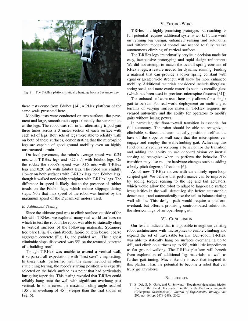
Fig. 8. The T-RHex platform statically hanging from a Sycamore tree.
these tests come from Edubot [14], a RHex platform of thesame scale presented here.
Mobility tests were conducted on two surfaces: flat pave-ment and large, smooth rocks approximately the same radiusas the legs. The robot was run in an alternating tripod gaitthree times across a 3 meter section of each surface witheach set of legs. Both sets of legs were able to reliably walkon both of these surfaces, demonstrating that the microspinelegs are capable of good ground mobility even on highlyunstructured terrain.
On level pavement, the robot’s average speed was 0.24m/s with T-RHex legs and 0.27 m/s with Edubot legs. Onthe rocks, the robot’s speed was 0.16 m/s with T-RHexlegs and 0.20 m/s with Edubot legs. The robot was slightlyslower on both surfaces with T-RHex legs than Edubot legs,though it walked noticeably straighter with T-RHex legs. Thedifference in speed is likely due to the presence of rubbertreads on the Edubot legs, which reduce slippage duringsteps. Note that max speed of the robot was limited by themaximum speed of the Dynamixel motors used.
E. Additional Testing
Since the ultimate goal was to climb surfaces outside of thelab with T-RHex, we explored many real-world surfaces onwhich to test the robot. The robot was able to statically clingto vertical surfaces of the following materials: Sycamoretree bark (Fig. 8), cinderblock, fabric bulletin board, coarseaggregate concrete (Fig. 1), and padded wall. The highestclimbable slope discovered was 55◦ on the textured concreteof a building roof.
Though T-RHex was unable to ascend a vertical wall,it surpassed all expectations with “best-case” cling testing.In these trials, performed with the same method as otherstatic cling testing, the robot’s starting position was expertlyselected on the brick surface as a point that had particularlyintriguing asperities. This testing revealed that T-RHex couldreliably hang onto the wall with significant overhang pastvertical. In some cases, the maximum cling angle reached135◦, an overhang of 45◦ (steeper than the trial shown inFig. 6).
V. FUTURE WORK
T-RHex is a highly promising prototype, but reaching itsfull potential requires additional systems work. Future workon refining leg design, enhanced sensing and autonomy,and different modes of control are needed to fully realizeautonomous climbing of vertical surfaces.
The T-RHex legs are primarily acrylic, a decision made foreasy, inexpensive prototyping and rapid design refinement.We did not attempt to match the overall spring constant ofRHex’s legs, a feature needed for dynamic running. Findinga material that can provide a lower spring constant withequal or greater yield strength will allow for more enhancedmobility. Additional materials considered include fiberglass,spring steel, and more exotic materials such as metallic glass(which has been used in previous microspine flexures [31]).
The onboard software used here only allows for a singlegait to be run. For real-world deployment on multi-angledterrains of varying surface material, T-RHex requires in-creased autonomy and the ability for operators to modifygaits without losing power.
In particular, the floor-to-wall transition is essential forfull autonomy. The robot should be able to recognize aclimbable surface, and automatically position itself at thebase of the slope or wall such that the microspines canengage and employ the wall-climbing gait. Achieving thisfunctionality requires scripting a behavior for the transitionand adding the ability to use onboard vision or inertialsensing to recognize when to perform the behavior. Thetransition may also require hardware changes such as addinga body pitch degree of freedom [6].
As of now, T-RHex moves with an entirely open-loop,scripted gait. We believe that performance can be improvedby adding torque sensing to the leg and tail actuators,which would allow the robot to adapt to large-scale surfaceirregularities in the wall, detect leg slip before catastrophicdetachment, and automatically use the tail to balance duringwall climbs. This design path would require a platformoverhaul, but offers a promising controls-based solution tothe shortcomings of an open-loop gait.
VI. CONCLUSION
Our results indicate that it is possible to augment existingrobot architectures with microspines to enable climbing andexpand the set of traversable terrain. Our robot, T-RHex,was able to statically hang on surfaces overhanging up to45◦, and climb on surfaces up to 55◦, with little impedimentto flat ground walking. The T-RHex platform will benefitfrom exploration of additional leg materials, as well asfurther gait tuning. Much like the insects that inspired it,this platform has the potential to become a robot that cantruly go anywhere.
REFERENCES
[1] Z. Dai, S. N. Gorb, and U. Schwarz, “Roughness-dependent frictionforce of the tarsal claw system in the beetle Pachnoda marginata(Coleoptera, Scarabaeidae),” Journal of Experimental Biology, vol.205, no. 16, pp. 2479–2488, 2002.
[2] R. G. Beutel and S. N. Gorb, “Ultrastructure of attachment specializa-tions of hexapods (Arthropoda): evolutionary patterns inferred froma revised ordinal phylogeny,” Journal of Zoological Systematics andEvolutionary Research, vol. 39, pp. 177–207, 2001.
[3] A. van Casteren and J. R. Codd, “Foot Morphology and SubstrateAdhesion in the Madagascan Hissing Cockroach, Gromphadorhinaportentosa,” Journal of Insect Science, vol. 10, 2010.
[4] A. T. Asbeck, S. Kim, W. R. Provancher, M. R. Cutkosky, andM. Lanzetta, “Scaling hard vertical surfaces with compliant microspinearrays,” in Robotics:Science and Systems, June 2005.
[5] A. K. Geim, S. V. Dubonos, I. V. Grigorieva, K. S. Novoselov, A. A.Zhukov, and S. Y. Shapoval, “Microfabricated adhesive mimickinggecko foot-hair,” Nature Materials, vol. 2, no. 7, pp. 461–463, 2003.
[6] M. J. Spenko, G. C. Haynes, J. A. Saunders, M. R. Cutkosky,A. A. Rizzi, R. J. Full, and D. E. Koditschek, “Biologically InspiredClimbing with a Hexapedal Robot,” Journal of Field Robotics, vol. 25,no. 4-5, pp. 223–242, 2008.
[7] A. Asbeck, S. Kim, A. McClung, and A. Parness, “Climbing wallswith microspines,” in IEEE International Conference on Robotics andAutomation, May 2006.
[8] A. Parness, N. Abcouwer, C. Fuller, N. Wiltsie, J. Nash, andB. Kennedy, “LEMUR 3: A limbed climbing robot for extreme terrainmobility in space,” in IEEE International Conference on Robotics andAutomation, 2017, pp. 5467–5473.
[9] A. Parness, M. Frost, N. Thatte, J. P. King, K. Witkoe, M. Nevarez,M. Garrett, H. Aghazarian, and B. Kennedy, “Gravity-independentrock-climbing robot and a sample acquisition tool with microspinegrippers,” Journal of Field Robotics, vol. 30, no. 6, pp. 897–915, 2013.
[10] K. Carpenter, N. Wiltsie, and A. Parness, “Rotary Microspine RoughSurface Mobility,” IEEE/ASME Transactions on Mechatronics, vol. 21,no. 5, pp. 2378–2390, 2016.
[11] Y. Liu, S. Sun, X. Wu, and T. Mei, “A wheeled wall-climbing robotwith bio-inspired spine mechanisms,” Journal of Bionic Engineering,vol. 12, no. 1, pp. 17–28, 2015.
[12] U. Saranli, M. Buehler, and D. E. Koditschek, “RHex: A simple andhighly mobile hexapod robot,” The International Journal of RoboticsResearch, vol. 20, no. 07, pp. 616–631, 2001.
[13] R. Altendorfer, N. Moore, H. Komsuoglu, M. Buehler, H. Brown Jr.,D. McMordie, U. Saranlie, R. Full, and D. Koditschek, “RHex: ABiologitcally Inspired Hexapod Runner,” Autonomous Robots, vol. 11,pp. 207–213, 2001.
[14] K. C. Galloway, G. C. Haynes, B. D. Ilhan, A. M. Johnson, R. Knopf,G. Lynch, B. Plotnick, M. White, and D. E. Koditschek, “X-RHex: Ahighly mobile hexapedal robot for sensorimotor tasks,” University ofPennsylvania, Philadelphia, PA, Tech. Rep., 2010.
[15] D. E. Koditschek, R. J. Full, and M. Buehler, “Mechanical aspectsof legged locomotion control,” Arthropod structure & development,vol. 33, no. 3, pp. 251–272, 2004.
[16] J. C. Spagna, D. I. Goldman, P.-C. Lin, D. E. Koditschek, and R. J.Full, “Distributed mechanical feedback in arthropods and robots sim-plifies control of rapid running on challenging terrain,” Bioinspiration& biomimetics, vol. 2, no. 1, p. 9, 2007.
[17] E. Moore, D. Campbell, F. Grimminger, and M. Buehler, “Reliablestair climbing in the simple hexapod ’RHex’,” in IEEE InternationalConference on Robotics and Automation, 02 2002, pp. 2222–2227.
[18] C. Li, P. B. Umbanhowar, H. Komsuoglu, D. E. Koditschek, and D. I.Goldman, “Sensitive dependence of the motion of a legged robot ongranular media,” Proceedings of the National Academy of Sciences,vol. 106, no. 9, pp. 3029–3034, 2009.
[19] Y.-C. Chou, W.-S. Yu, K.-J. Huang, and P.-C. Lin, “Bio-inspired step-climbing in a hexapod robot,” Bioinspiration & biomimetics, vol. 7,no. 3, p. 036008, 2012.
[20] B. D. Ilhan, A. M. Johnson, and D. E. Koditschek, “Autonomouslegged hill ascent,” Journal of Field Robotics, vol. 35, no. 5, pp. 802–832, August 2018.
[21] G. C. Haynes, J. Pusey, R. Knopf, A. M. Johnson, and D. E.Koditschek, “Laboratory on legs: An architecture for adjustable mor-phology with legged robots,” in Unmanned Systems Technology XIV,vol. 8387, no. 1. SPIE, 2012, p. 83870W.
[22] S. Roberts, J. Duperret, A. M. Johnson, S. v. Pelt, T. Zobeck, N. Lan-caster, and D. E. Koditschek, “Desert RHex technical report: Jornadaand White Sands trip,” University of Pennsylvania, Philadelphia, PA,Tech. Rep., 2014.
[23] T. Libby, A. M. Johnson, E. Chang-Siu, R. J. Full, and D. E.Koditschek, “Comparative design, scaling, and control of appendages
for inertial reorientation,” IEEE Transactions on Robotics, vol. 32,no. 6, pp. 1380–1398, 2016.
[24] K. Autumn, M. Buehler, M. Cutkosky, R. Fearing, R. J. Full, D. Gold-man, R. Groff, W. Provancher, A. A. Rizzi, U. Saranli et al., “Roboticsin scansorial environments,” in Unmanned ground vehicle technologyVII, vol. 5804. International Society for Optics and Photonics, 2005,pp. 291–302.
[25] S. Kim, A. T. Asbeck, M. R. Cutkosky, and W. R. Provancher,“SpinybotII: Climbing hard walls with compliant microspines,” inInternational Conference on Advanced Robotics. IEEE, 2005, pp.601–606.
[26] A. M. Hoover, S. Burden, X.-Y. Fu, S. S. Sastry, and R. S. Fearing,“Bio-inspired design and dynamic maneuverability of a minimally ac-tuated six-legged robot,” in 2010 3rd IEEE RAS & EMBS InternationalConference on Biomedical Robotics and Biomechatronics. IEEE,2010, pp. 869–876.
[27] R. Merz, F. Prinz, K. Ramaswami, M. Terk, and L. Weiss, “Shape de-position manufacturing,” in International Solid Freeform FabricationSymposium, 1994.
[28] L. E. Weiss, R. Merz, F. B. Prinz, G. Neplotnik, P. Padmanabhan,L. Schultz, and K. Ramaswami, “Shape deposition manufacturing ofheterogeneous structures,” Journal of Manufacturing Systems, vol. 16,no. 4, pp. 239–248, 1997.
[29] M. Binnard and M. R. Cutkosky, “Design by composition for layeredmanufacturing,” Journal of Mechanical Design, vol. 122, no. 1, pp.91–101, 2000.
[30] E. G. Merriam, A. B. Berg, A. Willig, A. Parness, and T. Frey, “Mi-crospine gripping mechanism for asteroid capture,” in 43rd AerospaceMechanisms Symposium. NASA Ames Research Center, May 2016,pp. 401–414.
[31] M. Martone, A. Parness, and A. Willig, “Design and testing of themicrospine gripper tool for the Asteroid Redirect Mission,” CaltechSURF Report, California Institute of Technology, Tech. Rep., 2016.