Embed Size (px)
Citation preview
ENGR-2300
Electronic Instrumentation
Quiz 3, Spring 2019
Name: ____________________ Please write you name on each page
Section: 1 or 2
4 Questions Sets, Total of 80 Points
LMS Portion, 20 Points
Question Set 1) Astable Multivibrator
Question Set 2) Combination & Sequential
Logic Circuits
Question Set 3) Diodes and Rectifiers
Question Set 4) Comparators and Schmitt
Triggers
On all questions:
SHOW ALL WORK. BEGIN WITH FORMULAS,
THEN SUBSTITUTE VALUES AND UNITS. No credit will be given for numbers that appear without justification.
Unless otherwise stated in a problem, provide 3 significant digits in answers.
It may be easier to answer parts of questions out of order.
If you need extra room, make it clear in the main problem statement that work is
continuing on the back of the page.
ENGR-2300 Spring 2019 Quiz 3 Name:____________________________
Electronic Instrumentation 2 / 13 K. R. Wilt & S. M. Sawyer
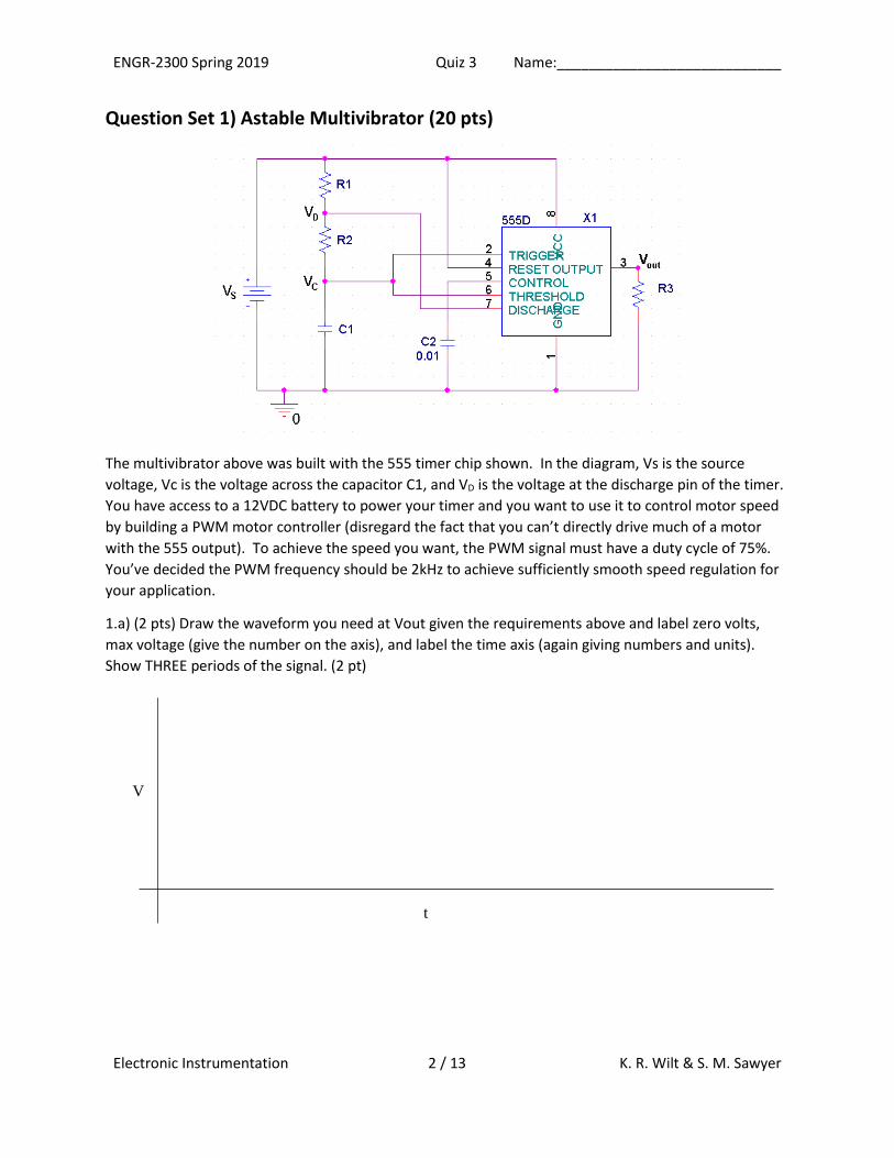
Question Set 1) Astable Multivibrator (20 pts)
The multivibrator above was built with the 555 timer chip shown. In the diagram, Vs is the source
voltage, Vc is the voltage across the capacitor C1, and VD is the voltage at the discharge pin of the timer.
You have access to a 12VDC battery to power your timer and you want to use it to control motor speed
by building a PWM motor controller (disregard the fact that you can’t directly drive much of a motor
with the 555 output). To achieve the speed you want, the PWM signal must have a duty cycle of 75%.
You’ve decided the PWM frequency should be 2kHz to achieve sufficiently smooth speed regulation for
your application.
1.a) (2 pts) Draw the waveform you need at Vout given the requirements above and label zero volts,
max voltage (give the number on the axis), and label the time axis (again giving numbers and units).
Show THREE periods of the signal. (2 pt)
V
t
t
ENGR-2300 Spring 2019 Quiz 3 Name:____________________________
Electronic Instrumentation 3 / 13 K. R. Wilt & S. M. Sawyer
1.b) (1 pt) What is the required ON time of the multivibrator?
1.c) (1 pt) What is the required OFF time of the multivibrator?
1.d) (4 pt) You only have a 2.2uF capacitor available but many resistors to select from, so find R1 & R2
that will achieve the desired on and off times.
1.e) (2 pt) Using the equation for astable multivibrator frequency provided on the crib sheet, confirm
that the operating frequency of your device is correct.
1.f) (2 pt) In theory, what are the maximum and minimum voltages that should be observed across
capacitor C1 while the circuit is functioning? (Give numbers and units please, ignore initial startup
conditions at the time power is first applied to the circuit)
ENGR-2300 Spring 2019 Quiz 3 Name:____________________________
Electronic Instrumentation 4 / 13 K. R. Wilt & S. M. Sawyer
1.g) (3 pt) When the transistor inside the 555 timer is closed, the output at pin 7 is grounded, and
therefore, equal to zero. When the transistor is open, the voltage at pin 7 can be found using the
voltage divider formed by R1 and R2. Find an expression for the voltage at pin 7 (when pin 7 is not
grounded) in terms of the voltage across the capacitor, Vc, the source voltage, Vs, and the two resistors
R1 and R2. [Hint: Recall how you calculate the voltage at the non-inverting input for a Schmitt trigger.]
Do not substitute values.
1.h) (2 pt) Use the equation in 1.g) to find the maximum and minimum voltage that is ever possible at
pin 7 when the transistor is open. [Hint: assume that the capacitor is completely discharged when
power is first applied to your circuit.]
ENGR-2300 Spring 2019 Quiz 3 Name:____________________________
Electronic Instrumentation 5 / 13 K. R. Wilt & S. M. Sawyer
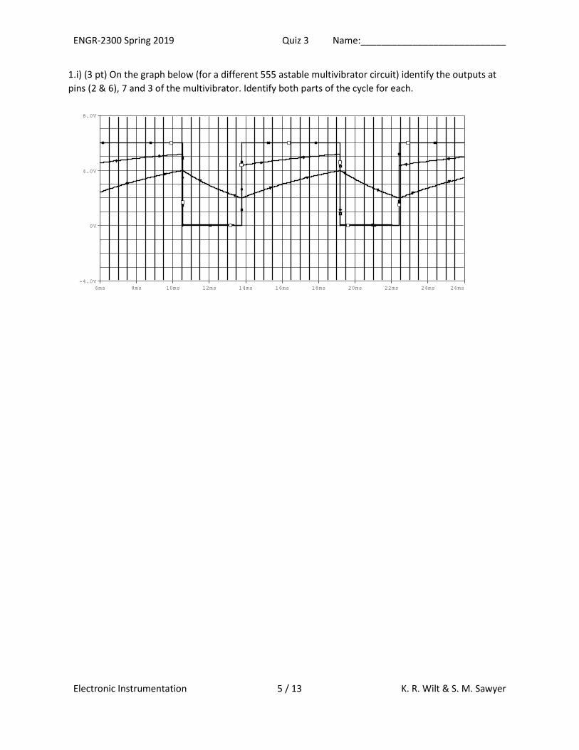
1.i) (3 pt) On the graph below (for a different 555 astable multivibrator circuit) identify the outputs at
pins (2 & 6), 7 and 3 of the multivibrator. Identify both parts of the cycle for each.
Time
6ms 8ms 10ms 12ms 14ms 16ms 18ms 20ms 22ms 24ms 26ms
V(R3:2) V(X1:DISCHARGE) V(C1:2)
-4.0V
0V
4.0V
8.0V
ENGR-2300 Spring 2019 Quiz 3 Name:____________________________
Electronic Instrumentation 6 / 13 K. R. Wilt & S. M. Sawyer
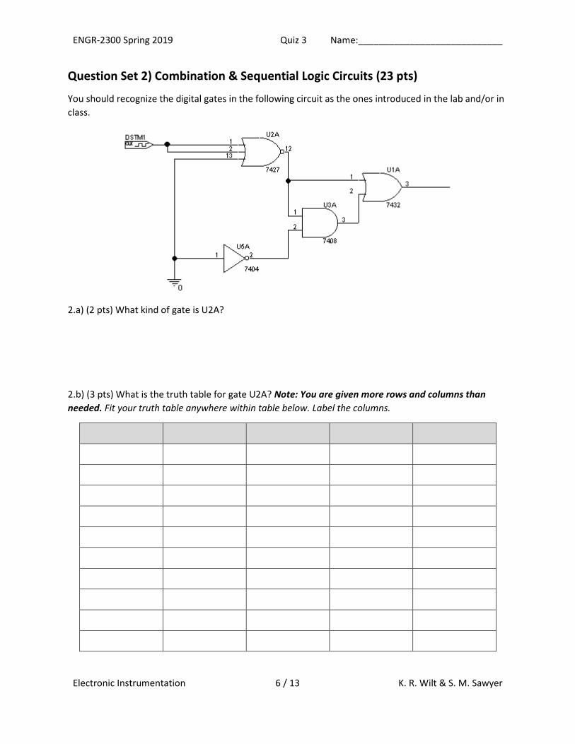
Question Set 2) Combination & Sequential Logic Circuits (23 pts)
You should recognize the digital gates in the following circuit as the ones introduced in the lab and/or in
class.
2.a) (2 pts) What kind of gate is U2A?
2.b) (3 pts) What is the truth table for gate U2A? Note: You are given more rows and columns than
needed. Fit your truth table anywhere within table below. Label the columns.
ENGR-2300 Spring 2019 Quiz 3 Name:____________________________
Electronic Instrumentation 7 / 13 K. R. Wilt & S. M. Sawyer
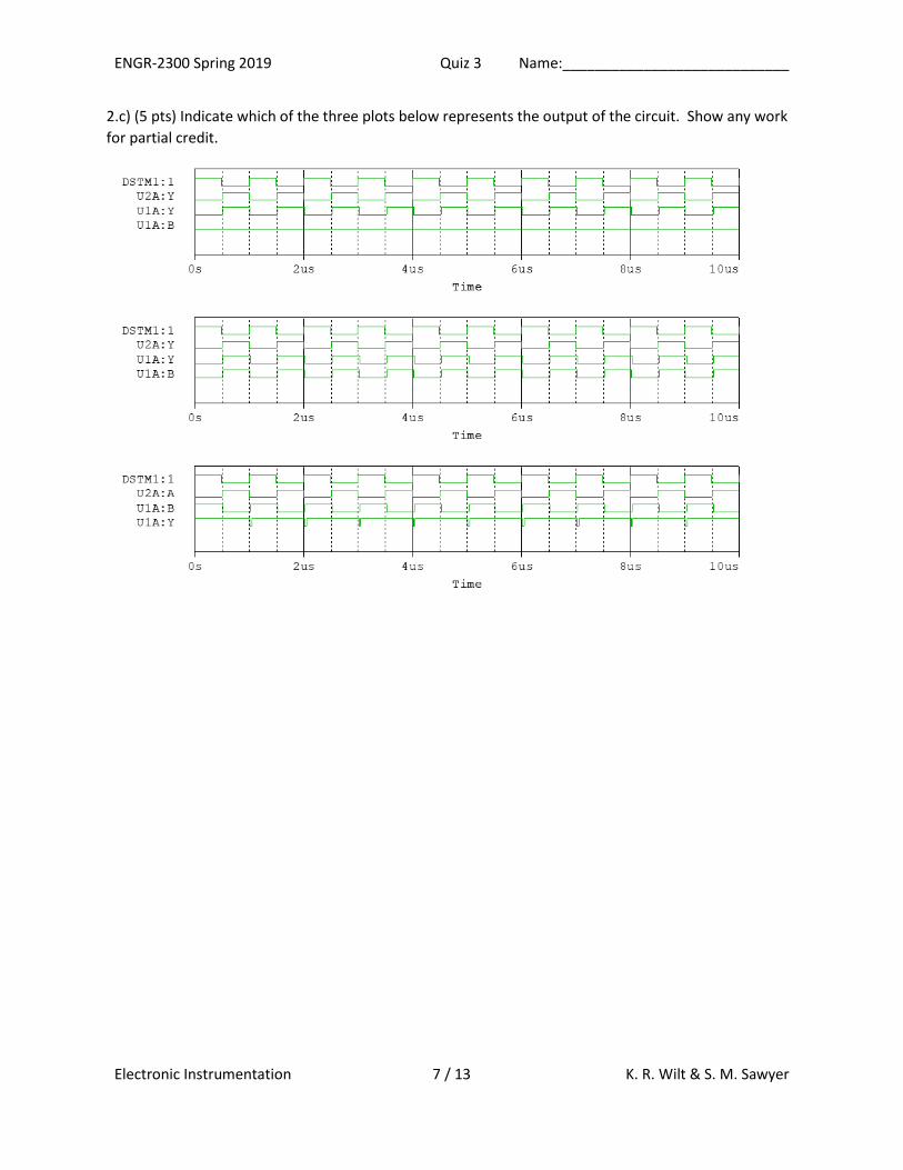
2.c) (5 pts) Indicate which of the three plots below represents the output of the circuit. Show any work
for partial credit.
ENGR-2300 Spring 2019 Quiz 3 Name:____________________________
Electronic Instrumentation 8 / 13 K. R. Wilt & S. M. Sawyer
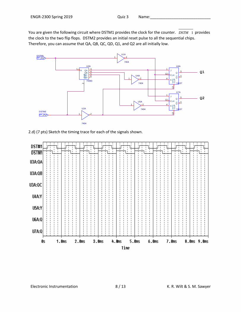
You are given the following circuit where DSTM1 provides the clock for the counter. 1DSTM provides
the clock to the two flip flops. DSTM2 provides an initial reset pulse to all the sequential chips.
Therefore, you can assume that QA, QB, QC, QD, Q1, and Q2 are all initially low.
2.d) (7 pts) Sketch the timing trace for each of the signals shown.
U6A
74107
1
4
13
3
212
J
K
CL
R
Q
QCLKU4A
7404
1 2
Q1
CLK
DSTM2
U3A
74393
1 3456
2
A QAQBQCQDC
LR
Q2
CLKDSTM1
U2A
7404
1 2
U1A
7404
1 2
U7A
74107
1
4
13
3
212
J
K
CL
R
Q
QCLKU5A
7404
1 2
ENGR-2300 Spring 2019 Quiz 3 Name:____________________________
Electronic Instrumentation 9 / 13 K. R. Wilt & S. M. Sawyer
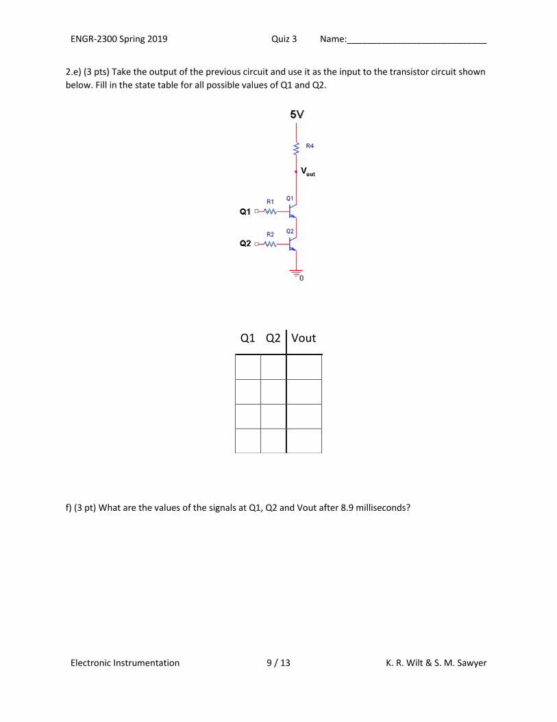
2.e) (3 pts) Take the output of the previous circuit and use it as the input to the transistor circuit shown
below. Fill in the state table for all possible values of Q1 and Q2.
f) (3 pt) What are the values of the signals at Q1, Q2 and Vout after 8.9 milliseconds?
Q1 Q2 Vout
ENGR-2300 Spring 2019 Quiz 3 Name:____________________________
Electronic Instrumentation 10 / 13 K. R. Wilt & S. M. Sawyer
Question Set 3) Diodes and Rectifiers (19 pts)
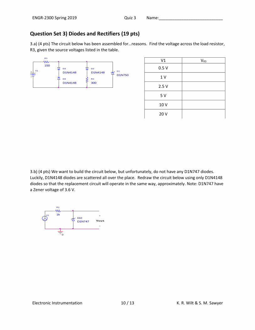
3.a) (4 pts) The circuit below has been assembled for…reasons. Find the voltage across the load resistor,
R3, given the source voltages listed in the table.
3.b) (4 pts) We want to build the circuit below, but unfortunately, do not have any D1N747 diodes.
Luckily, D1N4148 diodes are scattered all over the place. Redraw the circuit below using only D1N4148
diodes so that the replacement circuit will operate in the same way, approximately. Note: D1N747 have
a Zener voltage of 3.6 V.
D3
D1N4148
R1
150
D4
D1N4148
D2
D1N4148D1
D1N750
R3
300
V1
V1 VR3
0.5 V
1 V
2.5 V
5 V
10 V
20 V
D10
D1N747
V1
Vout
+
0
-
R1
1k
ENGR-2300 Spring 2019 Quiz 3 Name:____________________________
Electronic Instrumentation 11 / 13 K. R. Wilt & S. M. Sawyer
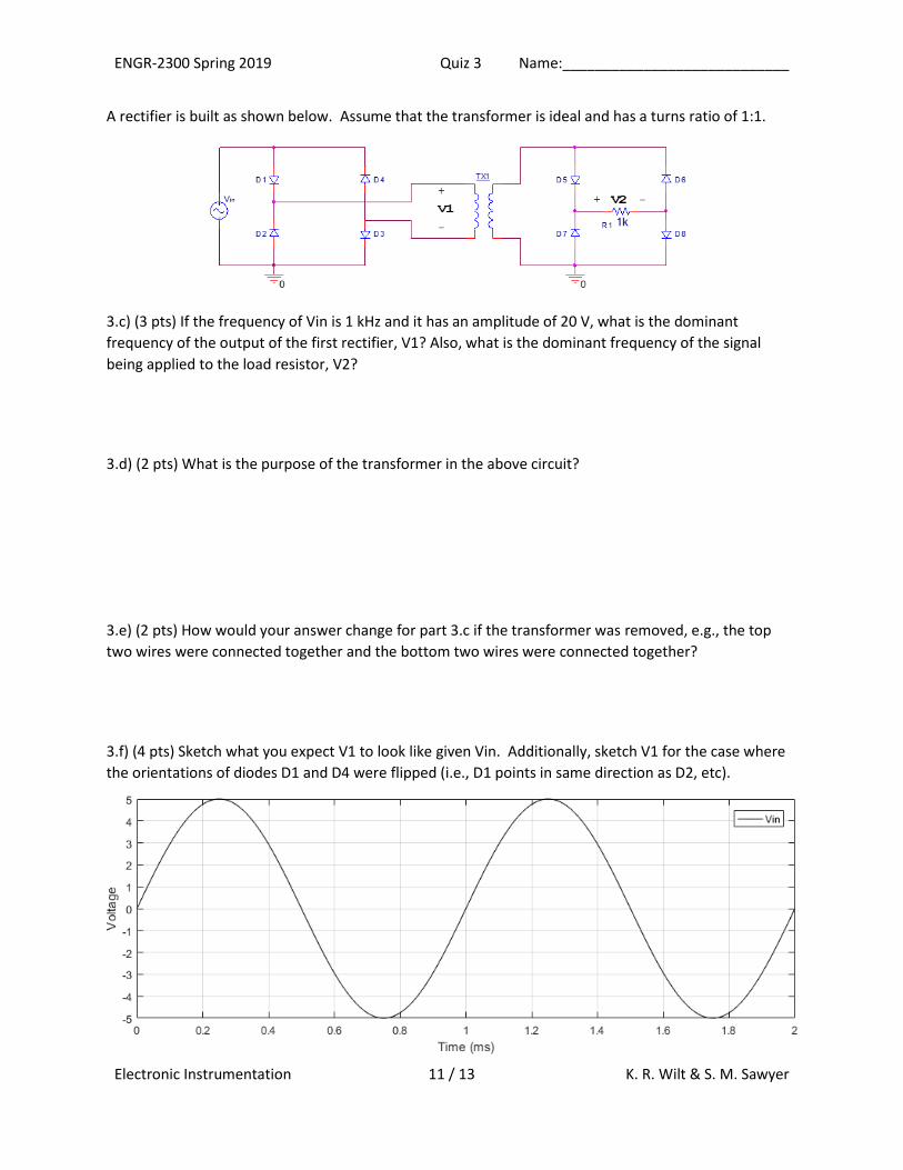
A rectifier is built as shown below. Assume that the transformer is ideal and has a turns ratio of 1:1.
3.c) (3 pts) If the frequency of Vin is 1 kHz and it has an amplitude of 20 V, what is the dominant
frequency of the output of the first rectifier, V1? Also, what is the dominant frequency of the signal
being applied to the load resistor, V2?
3.d) (2 pts) What is the purpose of the transformer in the above circuit?
3.e) (2 pts) How would your answer change for part 3.c if the transformer was removed, e.g., the top
two wires were connected together and the bottom two wires were connected together?
3.f) (4 pts) Sketch what you expect V1 to look like given Vin. Additionally, sketch V1 for the case where
the orientations of diodes D1 and D4 were flipped (i.e., D1 points in same direction as D2, etc).
ENGR-2300 Spring 2019 Quiz 3 Name:____________________________
Electronic Instrumentation 12 / 13 K. R. Wilt & S. M. Sawyer
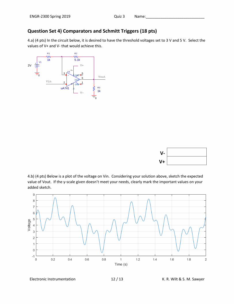
Question Set 4) Comparators and Schmitt Triggers (18 pts)
4.a) (4 pts) In the circuit below, it is desired to have the threshold voltages set to 3 V and 5 V. Select the
values of V+ and V- that would achieve this.
V-
V+
4.b) (4 pts) Below is a plot of the voltage on Vin. Considering your solution above, sketch the expected
value of Vout. If the y-scale given doesn’t meet your needs, clearly mark the important values on your
added sketch.
R2
5.1k
U1
uA741
+3
-2
V+
7V
-4
OUT6
OS11
OS25
Vout
Vin
0
V+
0
V-
V1
2V
R3
1k
R1
1k
ENGR-2300 Spring 2019 Quiz 3 Name:____________________________
Electronic Instrumentation 13 / 13 K. R. Wilt & S. M. Sawyer
4.c) (2 pts) In the circuit schematic of 4.a, R1 is replaced with a 0 Ω valued resistor. What would you call
the circuit now?
4.d) (2 pts) In the circuit schematic of 4.a, pins 2 and 3 are switched such that Vin is now connected to
the + input. What would you call the circuit now? Ignore the change from 4.c.
4.e) (2 pts) Assume a 100 Ω resistor was added in series between Vin and pin 2 of the schematic of 4.a.
Assuming Vin is 4 V, determine what the voltage drop is across this resistor, if possible. If not possible,
write “INDETERMINATE.”
4.e) (2 pts) On the crib sheet, we give you the schematic of an inverting comparator. How would you go
about making a non-inverting comparator?
4.f) (2 pts) Do you expect to take the optional final? Your answer here is NON-BINDING.
The optional final will:
cover all topics in the class,
Not have an LMS portion,
generally be more difficult than the quizzes (mainly because of points above),
replace your lowest quiz grade, which includes the LMS portion,
NOT replace your lowest quiz grade, IF the final grade is the lowest.
o That is: you cannot hurt you overall grade by attempting the final.
YES NO