Embed Size (px)
Citation preview

English XL™ VIT User Guide
Version 4, Released March 21, 2016
EXCEL TRIBOMETERS, LLC 237 Hanbury Road E, Suite 17 PMB 254
Chesapeake, VA 23322 [email protected] | www.exceltribometers.com
PHONE: 757-897-2853 | FAX: 888-804-3727
English XL™ VIT User Guide v.4
Page 2 of 32
Table Of Contents Section 1 Requirements for Slip Resistance Measurement 4 Section 2 Required Items 4 Section 3 How to Charge the System 5 Section 4 How to Remove the CO2 Cylinder 7 Section 5 How to Prepare the Standard Neolite Test Foot 8 Section 6 How to Fire the English XL™ VIT 11 Section 7 How to Clean Your Test Foot Calibration Tile 13 Section 8 How to Calibrate Your Test Foot 13 Section 9 Perform Dry Testing 18 Section 10 Perform Wet Testing 19 Section 11 Using the Stair Fixture 21 Section 12 General Advisories 23 Section 13 Test Foot Advisories 26 Section 14 Storing, Packing, and Shipping Your English XL™ VIT 29 Section 15 Glossary 31

English XL™ VIT User Guide v.4
Page 3 of 32
English XL VIT Components
Pressure Gauge
Regulator Adjusting Wheel
Mast
Handle
Actuation Button
Pneumatic Cylinder
Chassis Rail
Ankle Joint & Spring
Rubber Cushion “Dot”
Neolite™ Test Foot
Protractor & Pointer
CO2 Cylinder Cradle
English XL™ VIT User Guide v.4
Page 4 of 32
Section 1: Requirements for Slip Resistance Measurement
1. Be completely familiar with the entire English XL™ VIT User Guide before using the English XL™ VIT for slip resistance metering.
2. Follow the protocols in the English XL™ VIT User Guide when performing
slip resistance metering with the English XL™ VIT.
3. Assure the annual Instrument Calibration is current and your slipmeter is in good operating condition.
4. Perform Test Foot Calibration as described herein before and after each
metering episode and during extensive testing or testing that may otherwise alter the test foot to assure consistency with your test foot preparation technique and to confirm the test foot was not altered during the testing.
5. The English XL™ VIT is a scientific instrument that meters a value. Excel
Tribometers, LLC assures a properly maintained and properly operated meter produces consistent, accurate, and meaningful results. Ultimately, you will have to rely on your application of the appropriate sciences, together with your professional training, experience and judgment, to determine the extent to which any of your results are meaningful in the context of your analysis, whether you are evaluating a material or product, a specific injury event, or assessing the overall safety of a walking surface. Excel Tribometers, LLC cannot interpret your results for you.
Section 2: Required Items To use your English XL™ VIT, you will need:
Calibration tile and shim the same thickness as the calibration tile
Clean dry paper towels or soft cloth towels (plain, untreated)
Squeeze bottle with clean tap water
Test foot sanding system, “The Sander” preferred, or the English XL™ Sanding Pad with 5 inch disc
Clean filings brush, preferably cut to ¾-1 inch bristle length for added stiffness
An ankle spring retaining device (blank test foot, thin flat golf divot repair tool, head of a plastic fork, or similar item)
12 gram CO2 cartridges with lubricant (not for soda water)

English XL™ VIT User Guide v.4
Page 5 of 32
Section 3: How to Charge the System
1. Loosen the thumb screw on the regulator at least one (1) full turn so that when the system is charged there is a low reading (0-20 psi) on the pressure gauge.
2. Loosen the thumb screw on the CO2 cylinder cradle.
3. If you have an English XL™ VIT with Sequencer, ensure your actuation button is in the UP position before charging the CO2. Sequencer model shown on the left:

English XL™ VIT User Guide v.4
Page 6 of 32
4. Lay the cylinder in the CO2 holder so the larger rounded end of the cylinder is toward the thumb screw and insert the narrow flat end of the cylinder into the puncture pin sleeve.
5. Tighten the CO2 thumb screw until the pin punctures the cylinder cap and continue to tighten just enough to seal. Do not over-tighten the thumb screw.
6. Turn the regulator thumb screw in to set the pressure to 25 psi ± 2 psi on the
gauge.
7. Test fire the machine to verify the pressure setting after each adjustment. Adjustments to lower the pressure require firing to see the reduced pressure since the system is not self-venting.
8. If the instrument has not been used for an extended time and the piston does not extend when you actuate the button, set the pressure regulator to 0 psi, press the actuation button to depressurize the pneumatic cylinder, grasp the foot, and gently pull until the piston moves.
Puncture Pin Sleeve

English XL™ VIT User Guide v.4
Page 7 of 32
Section 4: How to Remove the CO2 Cylinder
1. If there is remaining CO2 in the cylinder, loosen the thumb screw on the regulator at least one (1) full turn and test fire the machine to verify the pressure is reduced.
2. Cover the CO2 cylinder and cradle with a towel and loosen the CO2 thumb screw until gas escapes.
3. If there is no remaining CO2 in the cylinder, loosen the CO2 thumb screw until the cylinder cap clears the puncture pin sleeve. Remove the CO2 in the cylinder from the cradle.
Puncture Pin Sleeve

English XL™ VIT User Guide v.4
Page 8 of 32
Section 5: How to Prepare the Standard Neolite Test Foot
1. Have an ankle spring retaining device available (blank test foot, golf divot repair tool, or similar item).
2. Without straining the low pressure plastic tubing, raise the pneumatic cylinder about 20 degrees, grasp the edges of the test foot, and pull back the ankle joint spring.
3. If using an ankle spring retaining tool, insert the tool between the bottom of the spring and the back of the white plastic ankle nut.

English XL™ VIT User Guide v.4
Page 9 of 32
4. Grasp the round white plastic ankle nut, then unscrew and remove the test foot.
5. If using a blank test foot as a retainer, grasp the round white plastic ankle nut, unscrew and remove the test foot, and replace with the blank foot to retain the nut.
6. The test foot must be dry before sanding. If wet, wipe thoroughly with a clean dry paper towel, allow to air dry until no visible moisture remains (about 1 minute), then sand. Blowing on the test foot or using oil-free compressed air will accelerate the drying.

English XL™ VIT User Guide v.4
Page 10 of 32
7. Perform 5 to 10 clockwise circles with the standardized test foot preparation device, “The Sander,” or with 180 grit hard-backed sandpaper on the English XL™ Sanding Pad. Use light pressure until a sanding dust “bagel” is produced on the sandpaper.
8. Clean the sanding dust from the test foot and the sanding disc with your dust brush. Always clean sanding dust away from any testing area. Always use a brush. Compressed air is not sufficient to dislodge sanding media that may be caught on the face of the test foot.
9. Replace the test foot on the round white plastic ankle nut without touching the Neolite face of the test foot.

English XL™ VIT User Guide v.4
Page 11 of 32
10. Adjust the tightness of the test foot on the ankle by pulling back the ankle joint spring. Grasp the round white plastic nut. Gently thread the test foot clockwise into the nut until you feel the end of the threads, then loosen ¼ turn. Only grasp the test foot by the edges. Never touch the face of the test foot with your fingers or other source of contamination.
Section 6: How to Fire the English XL™ VIT
1. Wrap your fingers around the horizontal handle at the top of the mast, with your
hand positioned so that the thumb of that hand presses on the top of the actuating button. Put the thumb of your other hand on the top of the adjusting wheel while putting your fingers of that hand on the frame side rail.
2. Exert just enough pressure on the handle to stabilize the machine and just
enough pressure with your thumbs to actuate the button or turn the adjusting wheel. There is no need to use a death grip on the machine or to jab or pound the button - think gentle and graceful.
English XL™ VIT User Guide v.4
Page 12 of 32
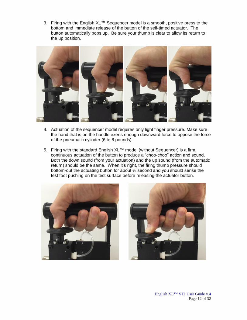
3. Firing with the English XL™ Sequencer model is a smooth, positive press to the bottom and immediate release of the button of the self-timed actuator. The button automatically pops up. Be sure your thumb is clear to allow its return to the up position.
4. Actuation of the sequencer model requires only light finger pressure. Make sure the hand that is on the handle exerts enough downward force to oppose the force of the pneumatic cylinder (6 to 8 pounds).
5. Firing with the standard English XL™ model (without Sequencer) is a firm, continuous actuation of the button to produce a “choo-choo” action and sound. Both the down sound (from your actuation) and the up sound (from the automatic return) should be the same. When it’s right, the firing thumb pressure should bottom-out the actuating button for about ½ second and you should sense the test foot pushing on the test surface before releasing the actuator button.

English XL™ VIT User Guide v.4
Page 13 of 32
6. When testing, always turn the adjusting wheel ¼ turn between strokes and always go from a more vertical mast to a more inclined mast. Always go from lower to higher readings of Slip Resistance Index.
Section 7: How to Clean your Test Foot Calibration Tile Your Test Foot Calibration Tile should be cleaned before each test foot calibration series.
1. Rub the test surface of the tile with a clean soft cloth with a few drops of liquid dish detergent soap and plenty of clean warm water.
2. Rinse thoroughly with a strong flow of clean warm water for sufficient time to
assure complete removal of the soap.
3. You may either dry the tile with a clean, dry, untreated, lint-free cloth or paper
towel, or proceed with the test foot calibration procedure.
4. Never contact the test surface of the Test Foot Calibration Tile with your fingers
or any other source of potential contamination.
5. Always store your Test Foot Calibration Tile in the packaging originally provided with the tile.
Section 8: How to Calibrate your Test Foot
You may want to calibrate your test foot at your base of operations if your testing does not involve more than 2 or 3 three test runs, or if there will not be contaminants that would affect the test foot. Otherwise, take your calibration tile with you to verify the continued calibration of your test foot if you suspect testing may have significantly altered the test foot.
1. Position the test foot calibration tile on a solid stable surface.
2. Prepare the dry test foot as described in Section 5 (How to Prepare the Standard Neolite Test Foot) and properly mount it on the English XL™ VIT.

English XL™ VIT User Guide v.4
Page 14 of 32
3. Position the slipmeter so the test foot is over the testing location on the test foot calibration tile. Support the rear of the slipmeter with a piece of solid, stable material of thickness equal to the test foot calibration tile thickness (ex. the shim provided with recently purchased tiles).
4. To clean any residual sanding dust from the test foot, initially set the mast with adjusting wheel to approximately 0.40 slip index.

English XL™ VIT User Guide v.4
Page 15 of 32
5. Wet the calibration tile under the test foot with clean tap water to provide an unbroken film of water. Fire the slipmeter. The foot should slip. Wet the tile again and repeat the cleaning slip 3 more times.
6. Set the mast with the adjusting wheel to a slip index of 0.05 less than the anticipated value of your tile, enough to have at least 3 firings before slip. Usually, setting the mast to a slip index of 0.15 is sufficient.

English XL™ VIT User Guide v.4
Page 16 of 32
7. Wet the tile again and fire. The test foot should not slip. Where the surface allows, always maintain an unbroken film of water for each test stroke.
8. Decline the mast ¼ turn of the adjusting wheel, wet the tile again, and fire. Repeat the sequence until the test foot slips. Read and record the slip index from the protractor to the nearest 0.01 Slip Resistance Index.
9. Rotate the calibration tile 90 degrees. Back off the adjusting wheel at least 3
turns so that you will fire at least 3 times before slip occurs. Test the same spot on the tile using the same sequence; wet the tile, fire, decline the mast ¼ turn of the adjusting wheel, wet the tile, fire, and repeat until the test foot slips. Read and record the slip index from the protractor to the nearest 0.01 Slip Resistance Index at each slip.
10. Repeat for at least 4 slips. If the first 1 or 2 readings are significantly higher than the next 3, these are considered “cleaning slips” and do not have to be considered calibration readings. Continue to rotate and test for 1 or 2 more readings to replace the “cleaning slips.”

English XL™ VIT User Guide v.4
Page 17 of 32
11. Your average reading should be the Certified Test Foot Calibration Tile value ± 0.03, or a value of 0.20 ± 0.03 on a non-certified test foot calibration tile.
a. If the reading is consistently low, the test foot is either contaminated or
sanded too flat. After assuring the test foot is not contaminated, sand with “The Sander” or alter your manual sanding technique by grasping higher on the test foot while sanding. Be sure the test foot is dry before sanding.
b. If the reading is consistently high, the test foot may be excessively rounded, oxidized, gouged by a rough testing surface, or contaminated and will need to be prepared again. After assuring the test foot is not contaminated, sand with “The Sander” or alter your manual sanding technique by grasping lower on the test foot while sanding. Be sure the test foot is dry before sanding.
c. If you suspect your test foot is contaminated, wash the Neolite with a warm soap and water solution, rinse until you are certain all soap is removed, wipe thoroughly with a clean dry towel, and air dry until there is no visible moisture. Then sand according to normal test foot preparation procedures until your calibration value is achieved.

English XL™ VIT User Guide v.4
Page 18 of 32
Section 9: Perform Dry Testing Test foot and test surface are both clean and dry
1. Prepare the test foot as described in Section 5 (How to Prepare the Standard Neolite Test Foot).
2. Position the slipmeter so the test foot is over the testing location on the test
surface. Keep in mind slip resistance properties may differ within close proximity of each other on non-uniform surfaces.
3. Set the mast with the adjusting wheel to a slip index sufficiently less than the
anticipated slip value to get at least 3 firings before slip, turning the adjusting wheel ¼ turn between each firing. Start at about 0.60 for smooth, hard surfaces (most clean, dry surfaces measure significantly higher than 0.50).
4. Fire the machine. The test foot should not slip.
5. Decline the mast by turning the adjusting wheel ¼ turn, fire, and repeat the
sequence until the test foot slips. Read and record the slip index from the protractor to the nearest 0.01 Slip Resistance Index.

English XL™ VIT User Guide v.4
Page 19 of 32
6. Prepare the test foot again as described in Section 5 (How to Prepare the Standard Neolite Test Foot).
7. Rotate the slipmeter or the test surface 90 degrees. Back off the adjusting wheel
at least 3 turns so that you will fire at least 3 times before slip occurs. Fire, decline the mast ¼ turn of the adjusting wheel, and repeat the sequence until the test foot slips. Read and record the slip index from the protractor to the nearest 0.01 Slip Resistance Index at each slip.
8. After each dry slip, prepare the test foot again as described in Section 5 (How to
Prepare the Standard Neolite Test Foot). 9. Normally, 4 orthogonal (N, E, S, W) readings on the same spot are sufficient to
assess slip resistance. Taking a total of 6-8 readings makes the measurement more statistically significant (if necessary), particularly if the surface being tested is not uniform.
10. Note any directional properties of the surface (grain, surface anomalies, etc.).
11. Upon completion of testing, remove the CO2 cylinder from the cradle as
described in Section 4 (How to Remove the CO2 Cylinder). Section 10: Perform Wet Testing Perform after all anticipated dry testing when practical When performing wet testing, spray or otherwise apply water to create an “unbroken film.” Some surface materials do not permit an unbroken film of water to form regardless of the amount of water applied. Remember, the intent is to simulate a water spill on the walking surface. You have applied sufficient water when you are assured the test foot and walking surface are wetted as they would be in a spill.
1. Be extra careful when doing wet testing of very low slip resistance index surfaces and the mast is near vertical; make sure to wait longer between firings for the test foot assembly to come to rest against its seat (the rubber dot) before firing again.
2. Prepare the dry test foot as described in Section 5 (How to Prepare the Standard Neolite Test Foot).
English XL™ VIT User Guide v.4
Page 20 of 32
3. Position the slipmeter so the test foot is over the testing location on the test surface. Keep in mind slip resistance properties may differ within close proximity of each other on non-uniform surfaces.
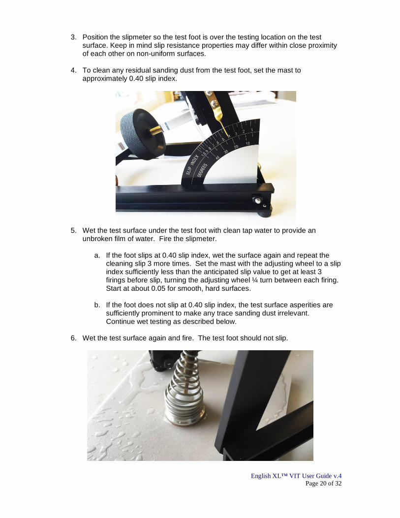
4. To clean any residual sanding dust from the test foot, set the mast to
approximately 0.40 slip index.
5. Wet the test surface under the test foot with clean tap water to provide an
unbroken film of water. Fire the slipmeter.
a. If the foot slips at 0.40 slip index, wet the surface again and repeat the cleaning slip 3 more times. Set the mast with the adjusting wheel to a slip index sufficiently less than the anticipated slip value to get at least 3 firings before slip, turning the adjusting wheel ¼ turn between each firing. Start at about 0.05 for smooth, hard surfaces.
b. If the foot does not slip at 0.40 slip index, the test surface asperities are sufficiently prominent to make any trace sanding dust irrelevant. Continue wet testing as described below.
6. Wet the test surface again and fire. The test foot should not slip.

English XL™ VIT User Guide v.4
Page 21 of 32
7. Decline the mast by turning the adjusting wheel ¼ turn, fire, and wet the tile again. Repeat until the test foot slips. Read and record the slip index from the protractor to the nearest 0.01 Slip Resistance Index.
8. Rotate the English XL™ VIT or test surface 90 degrees. Back off the adjusting
wheel at least 3 turns so that you will fire at least 3 times before slip occurs. Wet the surface under the test foot, fire, decline the mast ¼ turn of the adjusting wheel, and repeat until the test foot slips. Read and record the slip index from the protractor to the nearest 0.01 Slip Resistance Index at each slip.
9. Normally, 4 orthogonal (N, E, S, W) readings on the same spot are sufficient to assess slip resistance. Taking a total of 6-8 readings makes the measurement more statistically significant (if necessary), particularly if the surface being tested is not uniform.
10. Note any directional properties of the surface (grain, surface anomalies, etc.).
11. For wet testing with 4-test average slip resistance values below 0.20, re-sand if
and when a declining trend appears. For wet testing with 4-test average slip resistance values above 0.20, dry the test foot completely and re-sand after 8 slips unless a definitive declining trend appears before then.
12. Upon completion of testing, remove the CO2 cylinder from the cradle as described in Section 4 (How to Remove the CO2 Cylinder).
Section 11: Using the Stair Fixture The stair fixture is used to measure the slip resistance of stair nosings.
1. Support the English XL™ VIT on its side and locate the threaded holes on the bottom of the chassis rails.

English XL™ VIT User Guide v.4
Page 22 of 32
2. Attach the stair fixture to the bottom of the chassis with the two thumb screws that thread into the tapped holes in the bottom of the chassis.
3. Loosen the wing nut and turn the threaded rod in the appropriate direction to lengthen or shorten the stair fixture.
4. Once the proper height adjustment is made, tighten the wing nut to lock the assembly.

English XL™ VIT User Guide v.4
Page 23 of 32
5. Adjust the height of the peg-leg by putting the two front feet of the instrument on the leading edge of the stair tread. Adjust the threaded rod to place the chassis in the same plane as the stair tread. Level the chassis only if the stair tread is level.
Section 12: General Advisories
The output of the English XL™ VIT is always reported as “Slip Resistance Index,”
shortened to “Slip Index” on the Protractor. When metering a clean, dry surface, the measured Slip Resistance Index is also Static Coefficient of Friction (SCOF), but is still reported as Slip Resistance Index.
Acceptable tolerances for relatively uniform walkway surface materials are ±0.03 for slip resistance readings less than 0.50, and ±0.05 for slip resistance readings equal to or greater than 0.50, based on published 1998, 1999, 2000, and 2015 ILS results.
“It has been traditional practice to test each surface orthogonally. That is, to take four successive readings in the north, east, south and west orientations and record the results. For each set of readings, the results are normally averaged to obtain a net result for that panel. This method is not to be followed blindly, in that some surfaces have variability and directionality to their surface grain. Each number recorded is an actual traction measurement result and each one should be considered. If there is variability of results, take more than four readings on each spot and average for an acceptable confidence factor. Six or eight readings per surface test are recommended.” - William English, Pedestrian Slip Resistance How to Measure It and How to Improve It, 2nd Edition.
If, for some reason, you know that the reading you took was not a valid reading (e.g. you sneezed, the machine moved, and the test foot slipped or similar known deviation from a proper actuation of the instrument), do not record the value.
A slip during a test with the English XL™ VIT is defined as when the first full
extension of the pneumatic cylinder occurs. Partial creeps are not a slip.
If you can get a clean strike on a surface, you can take a measurement. If the test foot physically impinges on the side of a projection, the slip resistance is mechanical obstruction, as opposed to the interaction of surfaces in relative motion to each other and the reading is not valid.

English XL™ VIT User Guide v.4
Page 24 of 32
If you suspect the Brass Pointer has lost its “zero” through mishandling, improper storage, or shipping, you can re-zero it using a carpenter’s square. The Brass Pointer should cover the edge of the Protractor when the Mast is square to the chassis rail.
If the lower tube pops off under normal operating conditions, simply use scissors to cut ¼” from the end and reattach the tube to the nipple. The tubing is long enough to perform the cut several times before requiring a new tube.
Yellowing of the polymer tubes is a result of an accumulation of the lubrication in the CO2. If your tubing becomes noticeably yellowed in less than one year after Instrument Calibration, you are classified as a heavy user and it is recommended that Instrument Calibration be performed more often.
Always loosen the pressure regulator thumb screw and remove the CO2 cylinder
when finished testing to protect the pressure gauge.
Rarely, when the pressure is not able to be controlled, the regulator has blown and your machine needs service.
Do not pull on the test foot or connecting shaft while the system is pressurized.

English XL™ VIT User Guide v.4
Page 25 of 32
If the instrument has not been used for an extended time, and the piston does not extend when you actuate the button, set the pressure regulator to 0 psi, press the actuation button to depressurize the pneumatic cylinder, grasp the foot and gently pull until the piston moves.
When you raise the pneumatic cylinder, make sure you don’t pinch the tube at the top of the cylinder. If the tube gets pinched, a pinhole may form.
Simply use scissors to cut ¼” from the end and re-attach the tube to the nipple.
Rarely, the rubber cushion “dot” under the pneumatic cylinder is lost. Your machine will need service.

English XL™ VIT User Guide v.4
Page 26 of 32
Rarely, grease may be expelled from the exhaust port of the actuation valve. If this is an issue, clean the exhaust ports with a cotton swab periodically to avoid build-up.
Section 13: Test Foot Advisories
The condition of the test foot is the only significant variable in the accuracy and reliability of your testing results, provided your machine is in sound condition and is current with its annual Instrument Calibration and you have used your slipmeter according to this User Guide.
Test foot calibration must be performed as described before and after each metering episode, as well as during extensive testing or testing that may otherwise alter the test foot to assure consistency with your test foot preparation technique, and to confirm the test foot was not altered during the testing
It is advisable to calibrate the test foot at your base of operations if testing does not involve more than 2 or 3 three test runs, or if there will not be contaminants or conditions that would affect the test foot. Otherwise, take your calibration tile with you to verify the continued calibration of your test foot.
If there is no apparent directionality to the test surface and the readings are not within the tolerances specified in the Advisories at the end of this User Guide, and if a trend in the readings is evident, continue testing until the trend stabilizes. If the trend does not stabilize by 10 slips, stop and evaluate the possibility of contamination, surface variations, or other potential variables then prepare the test foot and begin again.
Surfaces with prominent, sharp asperities may drastically change the test foot during testing. Additional sanding may be required to restore the test foot. Check your test foot calibration if you suspect the test foot has been altered in any way.
English XL™ VIT User Guide v.4
Page 27 of 32
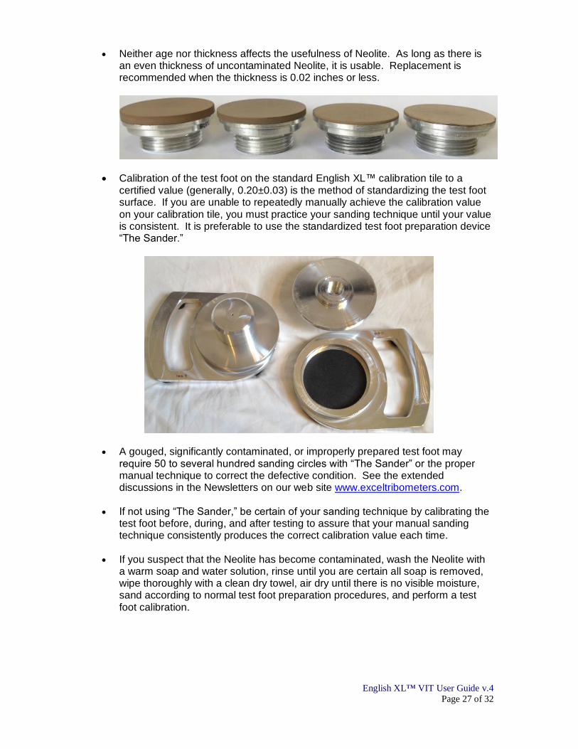
Neither age nor thickness affects the usefulness of Neolite. As long as there is an even thickness of uncontaminated Neolite, it is usable. Replacement is recommended when the thickness is 0.02 inches or less.
Calibration of the test foot on the standard English XL™ calibration tile to a certified value (generally, 0.20±0.03) is the method of standardizing the test foot surface. If you are unable to repeatedly manually achieve the calibration value on your calibration tile, you must practice your sanding technique until your value is consistent. It is preferable to use the standardized test foot preparation device “The Sander.”
A gouged, significantly contaminated, or improperly prepared test foot may require 50 to several hundred sanding circles with “The Sander” or the proper manual technique to correct the defective condition. See the extended discussions in the Newsletters on our web site www.exceltribometers.com.
If not using “The Sander,” be certain of your sanding technique by calibrating the
test foot before, during, and after testing to assure that your manual sanding technique consistently produces the correct calibration value each time.
If you suspect that the Neolite has become contaminated, wash the Neolite with
a warm soap and water solution, rinse until you are certain all soap is removed, wipe thoroughly with a clean dry towel, air dry until there is no visible moisture, sand according to normal test foot preparation procedures, and perform a test foot calibration.

English XL™ VIT User Guide v.4
Page 28 of 32
The cleanliness of the sandpaper is critical for preparing the Neolite test foot. The presence of sanding dust on the test foot may significantly affect results. As a general rule, the sandpaper is no longer clean enough if there is any visible Neolite ® sanding dust after vigorous brushing with the filings brush provided with your English XL™ VIT.
If not using “The Sander,” which is the preferred method, use the English XL™ Sanding Pad. If you are highly confident in your manual sanding technique, you may use sheet 180 grit Silicon Carbide sandpaper held securely flat on a hard smooth surface, such as a countertop or smooth, hard floor.

English XL™ VIT User Guide v.4
Page 29 of 32
The test foot must be dry before sanding. Always wipe a wet test foot thoroughly with a clean dry paper towel, allow to air dry for about 1 minute until all visible moisture is gone, then sand. If the test foot is sanded wet, the sandpaper will be clogged with sanding mud and will be ruined.
To avoid contamination of the test foot face, only grasp the test foot by the edges. Never touch the face of the test foot.
Section 14: Storing, Packing, and Shipping Your English XL™ VIT The English XL™ VIT soft carrying case is designed to fit only the instrument in the center compartment and its necessary accessories in the outer pouches. If you put other objects in the case with the meter, you risk damaging your instrument during shipment. When shipping your English XL™ VIT for annual Instrument Calibration, remove everything except the meter from the carrying case. Your calibration tile and Sander should be bubble wrapped and placed in the same packing box, but not in the soft case with the meter. Put the slipmeter in the soft case with the mast set to 0.05 slip resistance on the protractor (nearly vertical). Do not ship CO2 when you send your machine for Instrument Calibration.

English XL™ VIT User Guide v.4
Page 30 of 32
1. Install the foam piston bracket protector and stretch a thin rubber band around the ankle spring and attach the other end of the rubber band to the bolt under the pressure gauge to prevent damage to the test foot assembly.
2. Put the slipmeter in the soft case with the mast set to 0.05 slip resistance on the protractor (nearly vertical).
3. Fill the space in the soft case over the instrument with bubble wrap or air pillows to keep the meter seated at the bottom of the case. Your calibration tile and Sander should be bubble wrapped and placed in the same packing box, but not in the soft case compartment with the meter.

English XL™ VIT User Guide v.4
Page 31 of 32
4. Snap the case closed and put it in a box with enough packing materials such that nothing moves when shaken. The boxes we use when not shipping a Sander are 16x10x8 inches, with a layer of bubble wrap in the bottom of the box.
5. The boxes we use when shipping a Sander are 20x10x8 inches, with a layer of bubble wrap in the bottom of the box, and ample bubble wrap or air cushion to separate the Sander box (white, 8x8x2 inches) and the nylon instrument case.
Section 15: Glossary Available Slip Resistance – The traction a surface provides with or without contaminants. Biofidelity – Lifelike in appearance or response. Chassis – The lower portion of the English XL™ VIT that rests on the test surface. CO2 Cylinder – A small disposable metal container holding 12 grams (0.42 oz.) of compressed CO2 and often a small quantity of oil, used as a power source for certain air guns. Also known as a powerlet.

English XL™ VIT User Guide v.4
Page 32 of 32
Creep Arrest – Upon contact with the surface, the test foot slips and stops at less than full extension of the piston. DCOF – Dynamic Coefficient of Friction; μ = f/N for the force required to maintain motion once slipping has begun. Hydrodynamic Squeeze Film – Positive pressure in a fluid contained between two surfaces when two surfaces are moving toward each other. Instrument Calibration – The annual service performed by the manufacturer to clean, lubricate, repair, and verify the operation of an instrument. Mast – The upper portion of the English XL™ VIT whose inclination is varied during operation. Regulator – The device that reduces the CO2 pressure from the cartridge (840 psi at 70ºF) to the operating pressure of the English XL™ VIT 25±2 psi. Required Slip Resistance – Traction demand; what a body wants or needs to ambulate or to perform a maneuver or task. Residence Time – The duration of contact between two surfaces before the application of the horizontal force. SCOF – Static Coefficient of Friction; μ = f/N for the force required to initiate motion. Slip Resistance – The relative force which resists the tendency of the shoe or foot to slide along the walkway surface. Sticktion – Two surfaces squeeze out a liquid film and adhere to each other as a result of residence time. Test Foot – The 1.25±0.01 inches diameter Neolite™ slider pad mounted on an aluminum blank. The English XL™ VIT test foot uses a 1/8” thick slider pad (when new). Also known as the test-shoe. Test Foot Calibration – The process of preparing the test foot and measuring a standard tile to ensure the test foot and the instrument are operating properly. Variable Incidence Tribometer (VIT) – A tribometer whose thrust vector is controlled by adjusting the inclination of the mast relative to the test surface.
© EXCEL TRIBOMETERS, LLC. All Rights Reserved Worldwide. You may print this information for your personal use, but no part of this document may be otherwise reproduced in part or in full in other publications without the express, written approval of EXCEL TRIBOMETERS, LLC.