Embed Size (px)
Citation preview

English
Piping GuideCondensate Water System
2021-09-06 08:39
Revision 6Issued July 19, 2021
Disclaimer: The information contained in this document is general in nature and provided as reference material only. It is not to be used as a complete instruction unless supplemented by order specific documentation supplied by Jets Vacuum AS as a complete documentation package.
Every effort has been made to ensure that the information contained in the document is accurate at the time of creation, however, the information may not be complete or accurate for your purposes and no representation or warranty is given as to the accuracy of any of the information provided. Jets Vacuum AS reserves the right to make changes without notification.
© Copyright, Jets Vacuum AS. For more information go to www.jetsgroup.com.
2
Table of Contents
...........................................................................................................................................................................................Condensate Water System 1
...........................................................................................................................................................................................Table of Contents 2
IDS0107 ...........................................................................................................................................................................................Condensate Water Systems 3
IDS0285 ...........................................................................................................................................................................................Capacity Supermarket 5
IDS0289 ...........................................................................................................................................................................................Location of interceptor tank below freezer 6
IDS0109 ...........................................................................................................................................................................................Upward Piping Details 7
IDS0290 ...........................................................................................................................................................................................Nozzle fastening kit on the riser pipe 8
IDS0151 ...........................................................................................................................................................................................ED Valve and pipe connections 9
IDS0157 .........................................................................................................................................................................................Bends and Branches 10
IDS0148 .........................................................................................................................................................................................Transport Pockets 11
IDS0102 .........................................................................................................................................................................................Clamping 13
IDS0156 .........................................................................................................................................................................................Rodding Points 14
IDS0119 .........................................................................................................................................................................................Grey Water Interface Unit and Black Water Source 15
IDS0287 .........................................................................................................................................................................................Location of the Vacuum Pump 16
IDS0288 .........................................................................................................................................................................................Pressure side of piping 17
IDS0150 .........................................................................................................................................................................................Leak Test Procedure and Maintenance 18
IDS0110 .........................................................................................................................................................................................Startup Procedures 19
Condensate Water Systems Tel. +47 70 03 91 00www.jetsgroup.com
Information Data Sheet No. IDS0107 Doc. Rev.: 8 (2021-07-19)
3
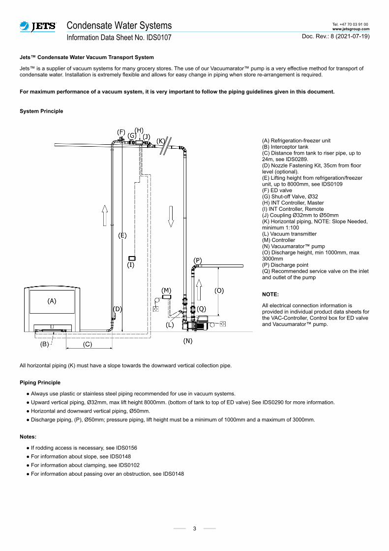
Jets™ Condensate Water Vacuum Transport System
Jets™ is a supplier of vacuum systems for many grocery stores. The use of our Vacuumarator™ pump is a very effective method for transport of condensate water. Installation is extremely flexible and allows for easy change in piping when store re-arrangement is required.
For maximum performance of a vacuum system, it is very important to follow the piping guidelines given in this document.
System Principle
(A) Refrigeration-freezer unit(B) Interceptor tank(C) Distance from tank to riser pipe, up to 24m, see IDS0289.(D) Nozzle Fastening Kit, 35cm from floor level (optional).(E) Lifting height from refrigeration/freezer unit, up to 8000mm, see IDS0109(F) ED valve(G) Shut-off Valve, Ø32(H) INT Controller, Master(I) INT Controller, Remote(J) Coupling Ø32mm to Ø50mm(K) Horizontal piping, NOTE: Slope Needed, minimum 1:100(L) Vacuum transmitter (M) Controller(N) Vacuumarator™ pump(O) Discharge height, min 1000mm, max 3000mm(P) Discharge point(Q) Recommended service valve on the inlet and outlet of the pump
NOTE:
All electrical connection information is provided in individual product data sheets for the VAC-Controller, Control box for ED valve and Vacuumarator™ pump.
All horizontal piping (K) must have a slope towards the downward vertical collection pipe.
Piping Principle
● Always use plastic or stainless steel piping recommended for use in vacuum systems.
● Upward vertical piping, Ø32mm, max lift height 8000mm. (bottom of tank to top of ED valve) See IDS0290 for more information.
● Horizontal and downward vertical piping, Ø50mm.
● Discharge piping, (P), Ø50mm; pressure piping, lift height must be a minimum of 1000mm and a maximum of 3000mm.
Notes:
● If rodding access is necessary, see IDS0156
● For information about slope, see IDS0148
● For information about clamping, see IDS0102
● For information about passing over an obstruction, see IDS0148
Condensate Water Systems Tel. +47 70 03 91 00www.jetsgroup.com
Information Data Sheet No. IDS0107 Doc. Rev.: 8 (2021-07-19)
4
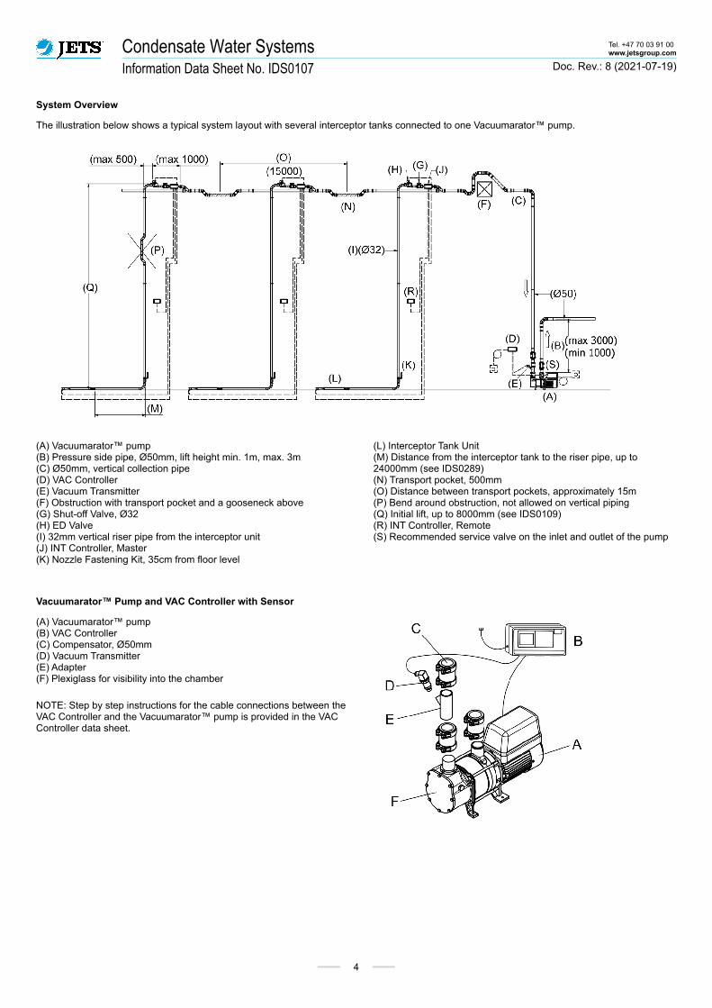
System Overview
The illustration below shows a typical system layout with several interceptor tanks connected to one Vacuumarator™ pump.
(A) Vacuumarator™ pump(B) Pressure side pipe, Ø50mm, lift height min. 1m, max. 3m(C) Ø50mm, vertical collection pipe(D) VAC Controller(E) Vacuum Transmitter(F) Obstruction with transport pocket and a gooseneck above(G) Shut-off Valve, Ø32(H) ED Valve(I) 32mm vertical riser pipe from the interceptor unit(J) INT Controller, Master(K) Nozzle Fastening Kit, 35cm from floor level
(L) Interceptor Tank Unit(M) Distance from the interceptor tank to the riser pipe, up to 24000mm (see IDS0289) (N) Transport pocket, 500mm(O) Distance between transport pockets, approximately 15m(P) Bend around obstruction, not allowed on vertical piping(Q) Initial lift, up to 8000mm (see IDS0109)(R) INT Controller, Remote(S) Recommended service valve on the inlet and outlet of the pump
Vacuumarator™ Pump and VAC Controller with Sensor
(A) Vacuumarator™ pump(B) VAC Controller(C) Compensator, Ø50mm(D) Vacuum Transmitter(E) Adapter(F) Plexiglass for visibility into the chamber
NOTE: Step by step instructions for the cable connections between the VAC Controller and the Vacuumarator™ pump is provided in the VAC Controller data sheet.
Capacity Supermarket Tel. +47 70 03 91 00www.jetsgroup.com
Information Data Sheet No. IDS0285 Doc. Rev.: 2 (2021-01-27)
5
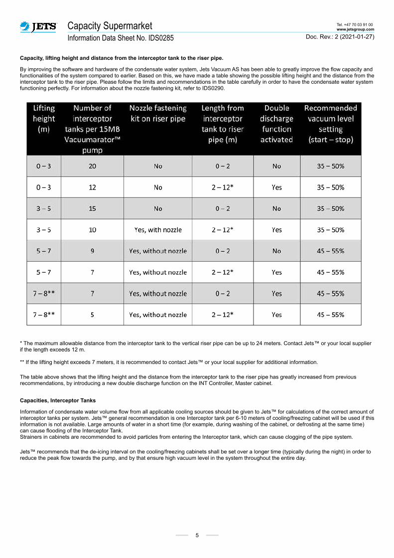
Capacity, lifting height and distance from the interceptor tank to the riser pipe.
By improving the software and hardware of the condensate water system, Jets Vacuum AS has been able to greatly improve the flow capacity and functionalities of the system compared to earlier. Based on this, we have made a table showing the possible lifting height and the distance from the interceptor tank to the riser pipe. Please follow the limits and recommendations in the table carefully in order to have the condensate water system functioning perfectly. For information about the nozzle fastening kit, refer to IDS0290.
* The maximum allowable distance from the interceptor tank to the vertical riser pipe can be up to 24 meters. Contact Jets™ or your local supplier if the length exceeds 12 m.
** If the lifting height exceeds 7 meters, it is recommended to contact Jets™ or your local supplier for additional information.
The table above shows that the lifting height and the distance from the interceptor tank to the riser pipe has greatly increased from previous recommendations, by introducing a new double discharge function on the INT Controller, Master cabinet.
Capacities, Interceptor Tanks
Information of condensate water volume flow from all applicable cooling sources should be given to Jets™ for calculations of the correct amount of interceptor tanks per system. Jets™ general recommendation is one Interceptor tank per 6-10 meters of cooling/freezing cabinet will be used if this information is not available. Large amounts of water in a short time (for example, during washing of the cabinet, or defrosting at the same time) can cause flooding of the Interceptor Tank. Strainers in cabinets are recommended to avoid particles from entering the Interceptor tank, which can cause clogging of the pipe system.
Jets™ recommends that the de-icing interval on the cooling/freezing cabinets shall be set over a longer time (typically during the night) in order to reduce the peak flow towards the pump, and by that ensure high vacuum level in the system throughout the entire day.
Location of interceptor tank below freezer Tel. +47 70 03 91 00www.jetsgroup.com
Information Data Sheet No. IDS0289 Doc. Rev.: 2 (2021-01-27)
6
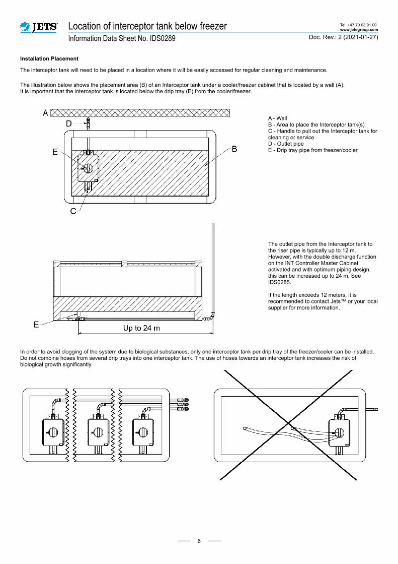
Installation Placement
The interceptor tank will need to be placed in a location where it will be easily accessed for regular cleaning and maintenance.
The illustration below shows the placement area (B) of an Interceptor tank under a cooler/freezer cabinet that is located by a wall (A). It is important that the interceptor tank is located below the drip tray (E) from the cooler/freezer.
A - WallB - Area to place the Interceptor tank(s)C - Handle to pull out the Interceptor tank for cleaning or serviceD - Outlet pipeE - Drip tray pipe from freezer/cooler
The outlet pipe from the Interceptor tank to the riser pipe is typically up to 12 m. However, with the double discharge function on the INT Controller Master Cabinet activated and with optimum piping design, this can be increased up to 24 m. See IDS0285.
If the length exceeds 12 meters, it is recommended to contact Jets™ or your local supplier for more information.
In order to avoid clogging of the system due to biological substances, only one interceptor tank per drip tray of the freezer/cooler can be installed.Do not combine hoses from several drip trays into one interceptor tank. The use of hoses towards an interceptor tank increases the risk of biological growth significantly.
Upward Piping Details Tel. +47 70 03 91 00www.jetsgroup.com
Information Data Sheet No. IDS0109 Doc. Rev.: 6 (2021-01-27)
7
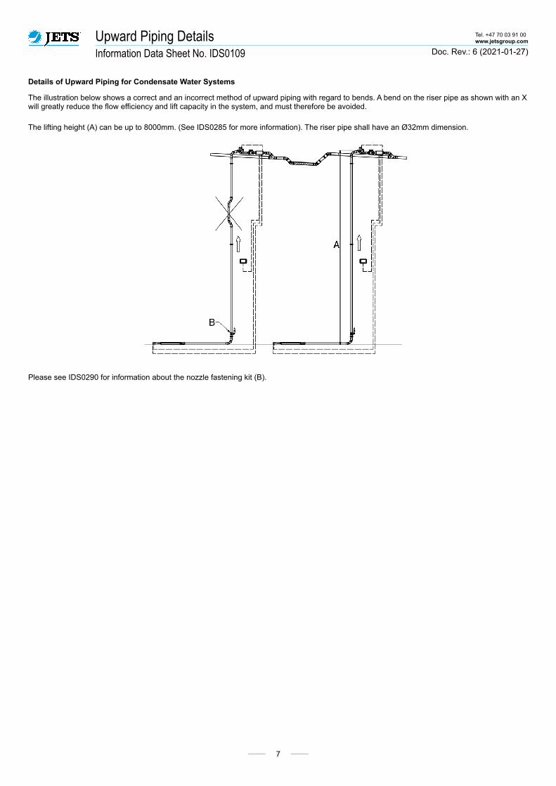
Details of Upward Piping for Condensate Water Systems
The illustration below shows a correct and an incorrect method of upward piping with regard to bends. A bend on the riser pipe as shown with an X will greatly reduce the flow efficiency and lift capacity in the system, and must therefore be avoided.
The lifting height (A) can be up to 8000mm. (See IDS0285 for more information). The riser pipe shall have an Ø32mm dimension.
Please see IDS0290 for information about the nozzle fastening kit (B).
Nozzle fastening kit on the riser pipe Tel. +47 70 03 91 00www.jetsgroup.com
Information Data Sheet No. IDS0290 Doc. Rev.: 2 (2021-01-27)
8
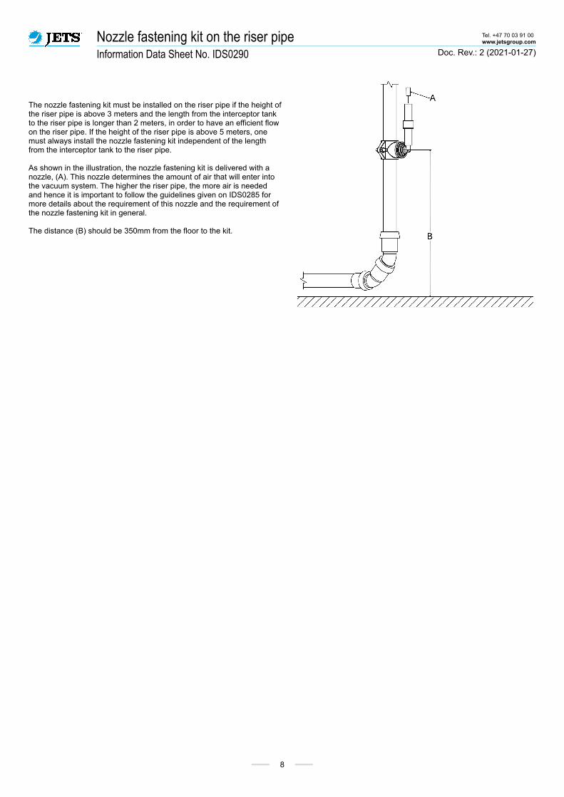
The nozzle fastening kit must be installed on the riser pipe if the height of the riser pipe is above 3 meters and the length from the interceptor tank to the riser pipe is longer than 2 meters, in order to have an efficient flow on the riser pipe. If the height of the riser pipe is above 5 meters, one must always install the nozzle fastening kit independent of the length from the interceptor tank to the riser pipe.
As shown in the illustration, the nozzle fastening kit is delivered with a nozzle, (A). This nozzle determines the amount of air that will enter into the vacuum system. The higher the riser pipe, the more air is needed and hence it is important to follow the guidelines given on IDS0285 for more details about the requirement of this nozzle and the requirement of the nozzle fastening kit in general.
The distance (B) should be 350mm from the floor to the kit.

ED Valve and pipe connections Tel. +47 70 03 91 00www.jetsgroup.com
Information Data Sheet No. IDS0151 Doc. Rev.: 6 (2021-01-27)
9
The ED Valve is specially designed for Jets™ Condensate Water Vacuum Piping Systems
(A) Piping, Ø32mm(B) Compression sleeve coupling Ø32mm(C) 2 x 45º pipe bends(D) ED valve, Ø32mm in, Ø32mm out(E) INT Controller, master(F) Shut-off valve, Ø32mm
(G) Coupling (reducer), Ø32mm to Ø50mm(H) 45º pipe bend(I) Branch pipe to horizontal collection pipe, Ø50mm(J) Piping, Ø50mm(K) Compression sleeve coupling Ø50mm(L) Piping, Ø50mm. This pipe together with (K) is optional, and will only be necessary if the length from the ED Valve to the coupling (G) can not be kept shorter than 1000mm.
The ED Valve must be placed a minimum of 100mm above the horizontal main pipe, and the Y-pipe (I) must never be connected inside a transport pocket.
Shut-off Valve
The shut-off valve with the short Ø32mm piping extension is joined with the ED valve pipe using a short pipe and a compression coupling (B) to the shut-off valve (F), as shown above.

Bends and Branches Tel. +47 70 03 91 00www.jetsgroup.com
Information Data Sheet No. IDS0157 Doc. Rev.: 5 (2021-01-27)
10
A branch is a separate section of a horizontal pipe. A horizontal pipe may consist of several branches.
The illustration below shows a typical arrangement with three branches, A, B and C, collecting several pipes from the interceptor tanks below the freezers. These three branches are connected to a vertical pipe, going down towards the Vacuumarator™ pump.
Branches are recommended to be as short as possible and with as few bends as possible. This is to reduce the accumulation of condensate water in the piping.
Jets™ recommends to install a rodding point at every main horizontal pipe.
Installation of branches must follow these rules:
1. Keep the amount of bends to a minimum, as this will increase the pressure drop and restrict the flow towards a vertical pipe. (Which may cause an accumulation of liquid downstream from the bend).
2. Connect a branch to a vertical pipe at an angle of 45°, or 2x45°. Never use a T-connection, as mentioned earlier.
3. Never reduce the pipe dimension towards the Vacuumarator™ pump, i.e. always go from smaller to larger pipe dimension when joining two pipes. NEVER go from a larger pipe dimension to a smaller pipe dimension.
Bends
Bends are to be installed with a large radius of curvature. Connecting of pipes is to be made at a maximum angle of 45º in the flow direction. In instances where a 90 degree angle cannot be avoided, an exception may be made and two 45 degree bends can be used.

Transport Pockets Tel. +47 70 03 91 00www.jetsgroup.com
Information Data Sheet No. IDS0148 Doc. Rev.: 7 (2021-07-19)
11
The proper installation and use of transport pockets is an important part of the entire vacuum piping system.
Transport pockets act as a collection point for slugs and a staging point for reforming the slug during transportation through a vacuum pipe system. The slug remains in these transport pockets until the next time the vacuum pipe system is activated and air once again enters the pipes, moving the slug in the flow direction in the pipe system (often to the next transport pocket if in a longer system).
Option for slope 1:100 :
H1= min. 50mm, max. 300mmH2= min. 50mm, max. 500mm
Preferred length (L) is 500mm, but max. 1000mm, if needed.
Option for slope 1:50 :
H = min. 50mm, max. 500mm
It is recommended that the distance (A), between the transport pockets, does not exceed 15 m.
Transport Pockets Tel. +47 70 03 91 00www.jetsgroup.com
Information Data Sheet No. IDS0148 Doc. Rev.: 7 (2021-07-19)
12
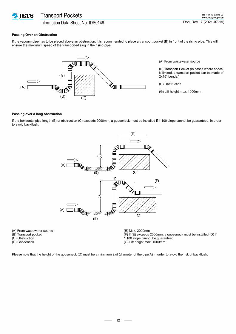
Passing Over an Obstruction
If the vacuum pipe has to be placed above an obstruction, it is recommended to place a transport pocket (B) in front of the rising pipe. This will ensure the maximum speed of the transported slug in the rising pipe.
(A) From wastewater source
(B) Transport Pocket (In cases where space is limited, a transport pocket can be made of 2x45° bends.)
(C) Obstruction
(G) Lift height max. 1000mm.
Passing over a long obstruction
If the horizontal pipe length (E) of obstruction (C) exceeds 2000mm, a gooseneck must be installed if 1:100 slope cannot be guaranteed, in order to avoid backflush.
(A) From wastewater source(B) Transport pocket(C) Obstruction(D) Gooseneck
(E) Max. 2000mm(F) If (E) exceeds 2000mm, a gooseneck must be installed (D) if 1:100 slope cannot be guaranteed.(G) Lift height max. 1000mm.
Please note that the height of the gooseneck (D) must be a minimum 2xd (diameter of the pipe A) in order to avoid the risk of backflush.
Clamping Tel. +47 70 03 91 00www.jetsgroup.com
Information Data Sheet No. IDS0102 Doc. Rev.: 12 (2021-10-08)
13
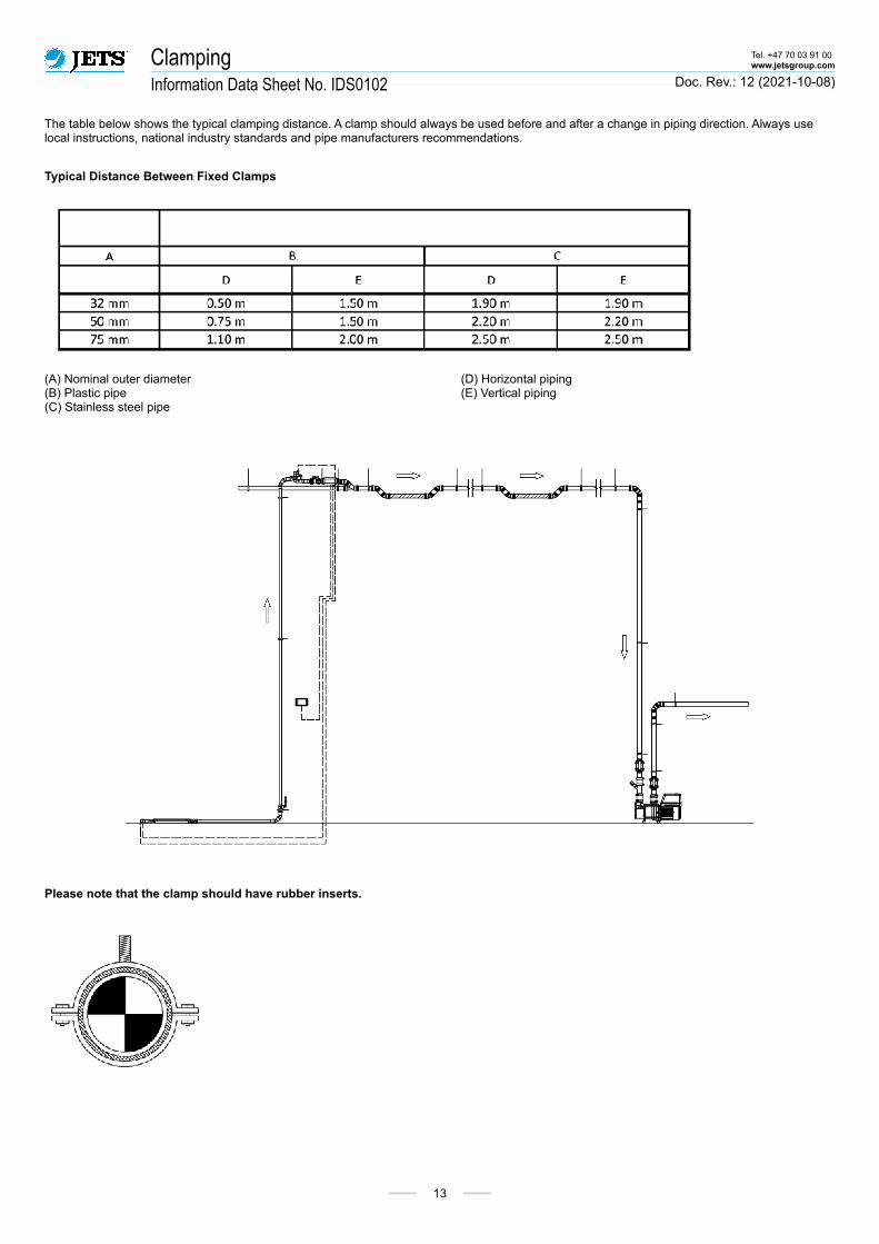
The table below shows the typical clamping distance. A clamp should always be used before and after a change in piping direction. Always use local instructions, national industry standards and pipe manufacturers recommendations.
Typical Distance Between Fixed Clamps
(A) Nominal outer diameter(B) Plastic pipe(C) Stainless steel pipe
(D) Horizontal piping(E) Vertical piping
Please note that the clamp should have rubber inserts.

Rodding Points Tel. +47 70 03 91 00www.jetsgroup.com
Information Data Sheet No. IDS0156 Doc. Rev.: 5 (2021-01-27)
14
Blocking of pipes may occur in wastewater piping. To ease maintenance of the pipe system, it is recommended to install rodding points so that all sections of a pipe can be accessed. Jets™ recommends installing rodding points:
● at the end of each branch.
● in front of bends and lifts.
Typically, this can be combined with a transport pocket. Please note that it is not a general recommendation that all transport pockets shall have a rodding point.
The following can be used:
Option 2 has an increased risk of spillage and should therefore only be used in areas where there is no room for option 1. In such situations, the alternative design shown below can also be used:
It is recommended to avoid rodding points in the following areas:
● near or through any galley, kitchen, food preparation or food storage areas.
● area around potable water tanks.
● medical spaces.
The distance between rodding points should not exceed 40 meters.

Grey Water Interface Unit and Black Water Source Tel. +47 70 03 91 00www.jetsgroup.com
Information Data Sheet No. IDS0119 Doc. Rev.: 4 (2021-01-14)
15
The connection of a grey water interface unit and a toilet is shown below. Please note that the maximum lifting height (A), for a grey water interfaceunit or toilet is 3000mm.
If sinks or toilets are to be installed, please contact your local distributor or Jets™ for detailed installation instructions.

Location of the Vacuum Pump Tel. +47 70 03 91 00www.jetsgroup.com
Information Data Sheet No. IDS0287 Doc. Rev.: 3 (2021-07-19)
16
The Vacuumarator™ pump should not be located above the main horizontal pipe and it is important that there is no lift before the Vacuumarator™ pump. This will cause accumulation of water in a water lock and will, in worst case, lead to malfunctioning of the system.
It is not recommended that the distance (A) from the floor to the Vacuumarator™ pump is more than 1500mm, in order to ensure that the Vacuumarator™ pump is available for easy maintenance.
Double Pump Installation
In larger stores, there is normally two or more Vacuumarator™ pumps. The piping design will be of great importance for the function of the system. The following rule must be followed.
● The piping connection must be placed on the top of the Vacuumarator™ pumps, as shown in this illustration, so that the liquid is evenly distributed between the pumps.
Pressure side of piping Tel. +47 70 03 91 00www.jetsgroup.com
Information Data Sheet No. IDS0288 Doc. Rev.: 2 (2021-07-19)
17
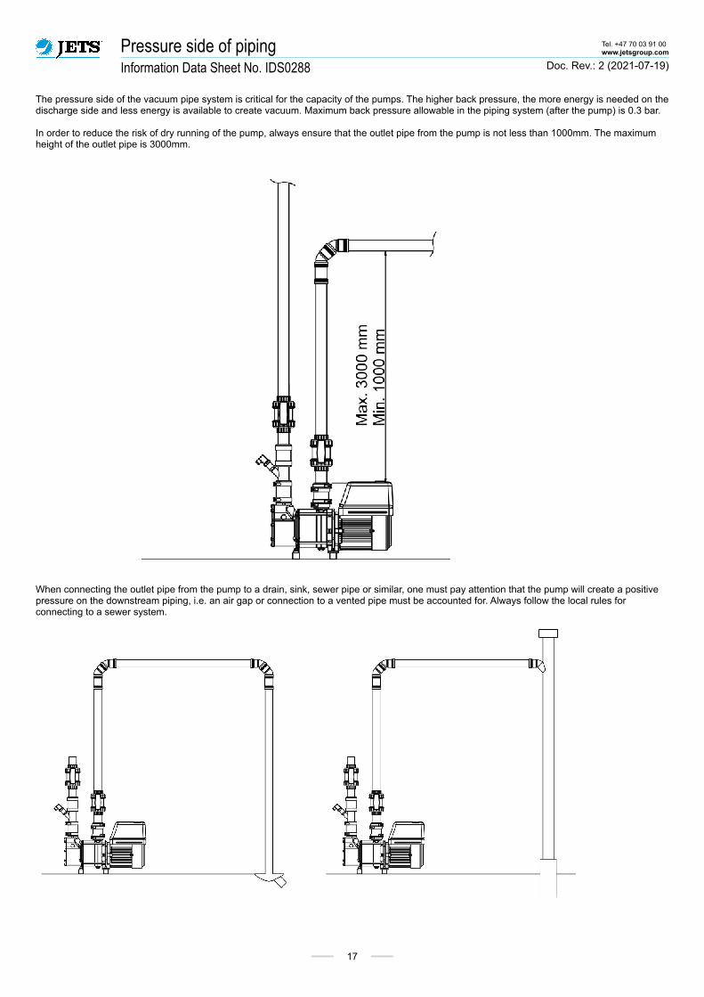
The pressure side of the vacuum pipe system is critical for the capacity of the pumps. The higher back pressure, the more energy is needed on the discharge side and less energy is available to create vacuum. Maximum back pressure allowable in the piping system (after the pump) is 0.3 bar.
In order to reduce the risk of dry running of the pump, always ensure that the outlet pipe from the pump is not less than 1000mm. The maximum height of the outlet pipe is 3000mm.
When connecting the outlet pipe from the pump to a drain, sink, sewer pipe or similar, one must pay attention that the pump will create a positive pressure on the downstream piping, i.e. an air gap or connection to a vented pipe must be accounted for. Always follow the local rules for connecting to a sewer system.

Leak Test Procedure and Maintenance Tel. +47 70 03 91 00www.jetsgroup.com
Information Data Sheet No. IDS0150 Doc. Rev.: 7 (2021-01-28)
18
All equipment supplied by Jets™ is controlled and tested prior to shipping from our manufacturing plant. However, leak tests must be performed after installation on-site to ensure that there are no leakages in the piping and the equipment.
A solid and leak free piping system is essential for a vacuum system. Leaks will cause malfunctioning of the system, increase the running time of the pumps and increase the energy consumption. It can also increase the risk of scaling.
Please follow the pipe manufacturers guidelines for installation and performance of air leak testing.
In general, Jets™ recommends the following:
Vacuum Pipes Only
A leak test is to be carried out on the complete vacuum pipe installation, without any interceptor tanks, toilets and/or grey water interface units connected.
1. Blind all pipes.
2. Increase the vacuum to 50% vacuum (0.5 barA) and close the outlet valve to the vacuum pump(s).
3. The maximum accepted leakage is a vacuum drop from 50% vacuum (0.5 barA) to 35% vacuum (0.65 barA) over a period of one hour.
Complete Vacuum System
A leak test is to be carried out on the complete vacuum system.
Factory vacuum setting is at 50%.
1. Connect all interceptor tanks, toilets and/or grey water interface units.
2. Increase the vacuum to 50% vacuum (0.5 barA) and close the outlet valve to the vacuum pump/s.
3. The maximum accepted leakage is a vacuum drop from 50% vacuum (0.5 barA) to 35% vacuum (0.65 barA) over a period of 20 minutes.
Condensate Water Systems, Maintenance
● Yearly visual inspection of the entire system for any leaks, both around the pump unit and any piping.
● If the pump starts and runs more than one time every 30 minutes without any of the interceptor tanks emptying within this period, a leak is indicated. Be aware of slowly dropping vacuum.
● It is easiest to check for leaks during quiet times, as noise from leaks can be detected easier.
● Chemicals or detergents, when used excessively, may cause foaming. Ensure that the use of this is not causing foaming inside the pump. If excessive foaming inside the tank is detected, it is recommended to install a pump flush system (please contact Jets™). It is recommended to use low or no foaming dishwasher detergent.
● For tank maintenance, it is highly recommended that the tank is cleaned every six months, using hot water at 60°C.
● The INT Controller Remote can be connected to the INT Controller Master to check information on the display per interceptor tank/ED valve/INT Controller Master. Then it can be used to perform remote operation of manual discharge of the interceptor tank, read out possible alarms and adjust opening time of the valve, if needed.

Startup Procedures Tel. +47 70 03 91 00www.jetsgroup.com
Information Data Sheet No. IDS0110 Doc. Rev.: 6 (2021-01-14)
19
Startup procedures should be carefully followed to ensure that the system will function according to specifications.
Vacuumarator™ pump
Fill the suction chamber to the top of the plexi glass with water.
VAC Controller
At first start-up, CVS (Auto Mode) and English language is set as default. All vacuum and alarm settings are pre-set.
To change the mode for the VAC Controller to Supermarket/condensate water mode, see start-up procedures in the product specific datasheet.
The Vacuumarator™ is set to start at 30% vacuum, and stop at 50% vacuum.
Check
All valves and controllers should be adjusted to the correct opening time of 2 seconds after the tank is empty.The factory setting for the opening time of the valve is 5 seconds.Use the INT Controller Remote panel to adjust the opening time by connecting the INT Controller Remote to the INT Controller Master using a normal patch cable. The opening time shall be adjusted so that the tank and riser pipe is emptied. The opening time should not be unnecessarily long, as this will increase the running time of the pump.
Test
Verify that the total system has no leaks and retains a stable vacuum level. The pump should start no more than once per 30 minutes when the system is not in use. Inspect all piping system connections for any leaks.