Embed Size (px)
Citation preview

Hakki Pilke
OH 27
LOG SPLITTER
– Instructions for assembly, operation and maintenance
– EU Declaration of Conformity
– Safety instructions
– Warranty terms
MAASELÄN KONE OY Valimotie 1, 85800 Haapajärvi
tel.08-7727300, fax.08-7727320 [email protected]
www.maaselankone.fi
The operator must read and understand these
instructions before operating the log splitter!
English

2 (39)
Hakki Pilke 27 Original Version 5-2014
TABLE OF CONTENTS
GENERAL SAFETY INSTRUCTIONS ............................................................................................. 4
WARNING SYMBOLS ...................................................................................................................... 5
Commissioning a New Machine .......................................................................................................... 8
Conveyor Work Position ...................................................................................................................... 9
Conveyor Transport Position ............................................................................................................. 11
The Machine from the Front .............................................................................................................. 12
The Machine from the Rear ............................................................................................................... 12
Filling cap of the oil tank ................................................................................................................... 12
Connecting the Machine to a Tractor ................................................................................................. 13
Electrically Driven Firewood Processor ............................................................................................ 14
Start and Stop Buttons........................................................................................................................ 15
Operation and Control of a Hydraulic Splitting System .................................................................... 16
Starting the Splitting Movement ........................................................................................................ 17
Splitting Blade Adjustment, Dismounting and Reassembly .............................................................. 17
Wood Length Adjustment .................................................................................................................. 18
Emergency Stop ................................................................................................................................. 18
Test Run ............................................................................................................................................. 20
Before Processing Firewood .............................................................................................................. 20
Processing the Firewood .................................................................................................................... 21
Safety Precautions for Cutting Trees: ................................................................................................ 22
Splitting the Last Cut Piece of Wood ................................................................................................. 24
Splitting a Split Piece of Wood .......................................................................................................... 24
Removing Wood Caught in the Splitting Blade................................................................................. 24
Using the Conveyor ........................................................................................................................... 25
Finishing the Work............................................................................................................................. 26
Transferring the Machine ................................................................................................................... 26
Cutting Blade ..................................................................................................................................... 27
Sharpening ......................................................................................................................................... 27
The setting must be approx. 0.7 mm. ................................................................................................. 27
Installing the Conveyor Drive Belt .................................................................................................... 30
Tightening Angular Gear Drive Belts in Model TR60 ...................................................................... 31
Belt tightness: ..................................................................................................................................... 31 Tightening Angular Gear Drive Belts in Model TRS60 .................................................................... 31

3 (39)
Hakki Pilke 27 Original Version 5-2014
Machine Lubrication .......................................................................................................................... 32
Hydraulic Oil...................................................................................................................................... 32
Angular Gear ...................................................................................................................................... 32
Splitting Mechanism .......................................................................................................................... 32
Operation ............................................................................................................................................ 33
Adjustments ....................................................................................................................................... 34
Adjusting the Travel of the Splitting Beam ....................................................................................... 34
Towards the initial position................................................................................................................ 34 The stroke is shortened ...................................................................................................................... 34 Splitting beam .................................................................................................................................... 34
Disturbances in the Splitting Mechanism, Their Reparation and Prevention .................................... 35
Hydraulic System Pressure Adjustment ............................................................................................. 36
Storing the Machine ........................................................................................................................... 36
Technical Specifications: ................................................................................................................... 37
EU DECLARATION OF CONFORMITY OF MACHINE.............................................................. 38
Manufacturer: Maaselän Kone Oy ..................................................................................................... 38
Guarantee terms ................................................................................................................................. 38
The guarantee covers ............................................................................................ 39
The guarantee does not cover ............................................................................... 39

4 (39)
Hakki Pilke 27 Original Version 5-2014
GENERAL SAFETY INSTRUCTIONS Great care must be taken in the operation of this machine as well as its connection to
a power source, such as a tractor, so that neither the person connecting it nor other
persons nearby are subjected to injury.
In order to avoid accidents, the machine must not be operated by persons who are
tired, intoxicated or under the influence of drugs or not sufficiently capable of
controlling their actions.
The connection of the machine to the power source must be carried out by only one
person at any one time.
The risk zone around the machine is 10 metres. Except for the operator, no other
person is allowed within this area during connection and operation.
If persons other than the operator remain within the risk zone, the operator must make
them aware of the dangers related to the operation of the machine.
The work site and its surroundings must be prepared prior to operating the machine to
ensure safe working conditions. The area must be sufficiently lit for operation. If the
light is scarce, the machine must not be used without sufficient and appropriate
additional lighting.
The Hakki Pilke Firewood Processor is designed for making firewood of lopped trees
and other lopped and pre-processed wood, such as pre-cut logs. Do not process wood
material that has been processed in any other way, such as construction waste. The
manufacturer of the machine is not responsible for any damages or injuries that
processing such wood may cause to the machine or operator.
The work capacity of the machine, i.e. the maximum wood diameter of 25 cm and the
maximum wood length of 55 cm, must not be exceeded.
The machine must not be operated, if the operator is not:
- familiar with these instructions;
- familiar with risk situations that may occur during the operation of the machine;
- able to act, should a dangerous situation occur during operation.
If the machine is faulty or contains a broken part that the operator is not able to repair
or replace, the operator must contact the seller, manufacturer or importer of the
machine.
The operator must always check all components before connecting the machine
to the tractor or operating it. Under no circumstances should the machine be
used if even a small amount of wear and tear is detected in its structure or
components! The faulty parts must be repaired or replaced with new ones!

5 (39)
Hakki Pilke 27 Original Version 5-2014
WARNING SYMBOLS
DANGER ZONE
BEWARE OF THE CUTTING
BLADE
ONLY ONE PERSON AT A
TIME IN THE WORK AREA
SHUT DOWN BEFORE
MAINTENANCE
BEWARE OF MOVING
PARTS
RISK OF ENTANGLEMENT
WITH THE CARDAN
SHAFT
RISK OF CRUSHING
DO NOT GO UNDER THE
CONVEYOR
MAX CONVEYOR TILT
ANGLE
BEWARE OF THE
SPLITTING BLADE

6 (39)
Hakki Pilke 27 Original Version 5-2014
READ THE MANUAL BEFORE
USE
USE PROTECTIVE
EQUIPMENT
USE PROTECTIVE
EQUIPMENT
ALWAYS GRAB A LOG BY
THE SIDES
MAX RPM
Scale
HYDRAULIC OIL
LEFT ROTATION
RIGHT ROTATION
LIFTING POINT FOR
FORKLIFT
LIFTING POINT FOR HOOK
EMERGENCY STOP

7 (39)
Hakki Pilke 27 Original Version 5-2014
Machine Lifting Points
The machine includes lifting points designed for a forklift fork and a line or chain.
The following figure on the left shows the lifting points for a line or chain.
The figure on the right shows the lifting points for a forklift fork. Always insert one
of fork prongs through the frame preventing sideslip.
Lifting
points.

8 (39)
Hakki Pilke 27 Original Version 5-2014
Commissioning a New Machine After unpacking the machine, dispose of the packaging material in an
environmentally friendly way.
Install the loose parts supplied with the machine:
1. Place the cross-cut cradle extension into the square pipe in the cradle frame.
2. Adjust the extension to
the desired length and lock
it in place with a locking
nut.
3. Adjust the
extreme position of
the cradle (towards
the user) with the
two nuts in the
lower part of the
cradle. There
should be approx.
3 mm between the
cradle cover and
the rocking cover.
4. Install the adjustment lever of the splitting blade
onto the joint pin on the machine frame. Add the
washer and lock the parts in place with a split
cotter.
Cradle
cover
Rocking cover

9 (39)
Hakki Pilke 27 Original Version 5-2014
5. Install the winch handle by screwing the handle on the root of the shaft.
Screw the locking nut of the handle on the shaft.
Conveyor Work Position
1. Make sure that the winch is locked to the removal conveyor and that hook latch
is intact as shown below.
Tighten the nut evenly
with the winch shaft.
There should be approx. 5 mm
between the nut and the handle
frame.
Winch operation:
When the handle is turned clockwise,
the brake loosens and the strap
tightens on the spool. When the
handle is turned counter-clockwise,
the brake engages and the strap
loosens from the spool.
Hook latch

10 (39)
Hakki Pilke 27 Original Version 5-2014
8. Turn the belt holder to the side of the conveyor.
2. Unwind some line from
the winch.
3. Push the conveyor towards the machine and release
its lock by lifting the locking handle.
4. Pull the conveyor until
the winch line tightens. 5. Lower the conveyor with
the winch.
6. Extend the conveyor to its
full length.
7. Adjust the conveyor to the desired inclination with
the winch and lock the extension with the lock at the
bottom of the conveyor.

11 (39)
Hakki Pilke 27 Original Version 5-2014
Conveyor Transport Position Bring the conveyor into the transport position by reversing the steps described in section “Conveyor
Work Position”.
Always ensure that the
conveyor is in the transport
position before transporting the
machine.
12 (39)
Hakki Pilke 27 Original Version 5-2014
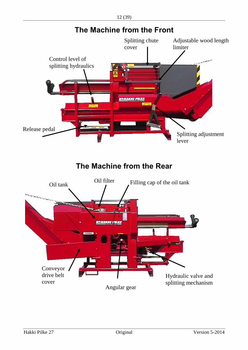
The Machine from the Front
The Machine from the Rear
Splitting chute
cover
Adjustable wood length
limiter
Splitting adjustment
lever
Control level of
splitting hydraulics
Release pedal
Oil filter Oil tank Filling cap of the oil tank
Conveyor
drive belt
cover Angular gear
Hydraulic valve and
splitting mechanism

13 (39)
Hakki Pilke 27 Original Version 5-2014
Connecting the Machine to a Tractor
Always make sure you are on your own when connecting the machine. Ensure there
are no other persons or animals in the tractor cabin, who could accidentally touch the
controls during the connection process. Check all connection parts of the machine
and tractor before connection. Do not connect the machine to faulty devices or parts.
Always carry out the connection in a calm manner and in one go, without
interruption. Secure the locking of the pins with appropriate cotters. After finishing
the connection, check that the procedure has been completed successfully.
When connecting the articulated shaft, follow the instructions on safe connection
provided by the shaft manufacturer. Connecting an unprotected shaft to the machine
is absolutely forbidden!
The maximum power requirement of the machine is 7.5 kW, and the articulated
shaft should be dimensioned accordingly.
The following figure shows the tractor attachment points.
Push arm attachment
point
Lift arm attachment points

14 (39)
Hakki Pilke 27 Original Version 5-2014
Electrically Driven Firewood Processor In addition to the instructions in this manual on the safe operation and service of a
tractor driven machine, the following points must be observed when operating the
electrically driven machine model TRS 60:
The machine must be placed on a base from which it cannot move or fall during
operation.
The electric motor IP- rating is 55.The fuse rating is min. 16A slow.
The machine is equipped with a male contact. When plugging in the electrical cable,
ensure that:
- the capacity of the cable is high enough;
- the cable and plug are intact;
- the cable is led from the socket to the machine by a route that protects the cord from
damage and ensures it cannot cause damage or injury outsiders;
- when the cable is installed across a passageway, it is dug in the ground and covered
so that the users of the passageway cannot come into contact with the cable;
- the cable is led directly from the plug contact to the contact on the machine (see the
following figure) and never installed on the side where the operator is processing
firewood.
Before starting the machine, make sure that the angular gear cover is in place so
that it is not possible to touch the gear.
The machine must absolutely not be operated if this cover is not in place.
Position of the cover when
powered by an electrical
motor
Machine contact

15 (39)
Hakki Pilke 27 Original Version 5-2014
Start and Stop Buttons
The start box is on the left hand side of the cutting blade.
The machine start button is the green button on the box.
The red button on the box is the stop button.
A tractor-driven machine cannot be halted from the red stop button of an
electrically driven machine!!!
Make sure that the motor starts running in the correct direction when you start
it.
The direction of rotation is correct if the teeth of the cutting blade run downwards
seen from the front of the machine. The direction is incorrect if the teeth run
upwards, and in this case the machine must be stopped immediately. Only
persons authorised to do so may change the rotation direction.
An electrically driven machine must always be stopped for transportation.
In order to prevent children and other outsiders from starting the machine, the
electrical cable must always be disconnected during breaks or at the end of firewood
processing.
Position of the cover when powered
by a tractor
Angular gear shaft for
articulated shaft
.
16 (39)
Hakki Pilke 27 Original Version 5-2014
If an electrically driven machine is driven by a tractor, all instructions in this manual
on the safe operation of a tractor-driven machine must be followed.
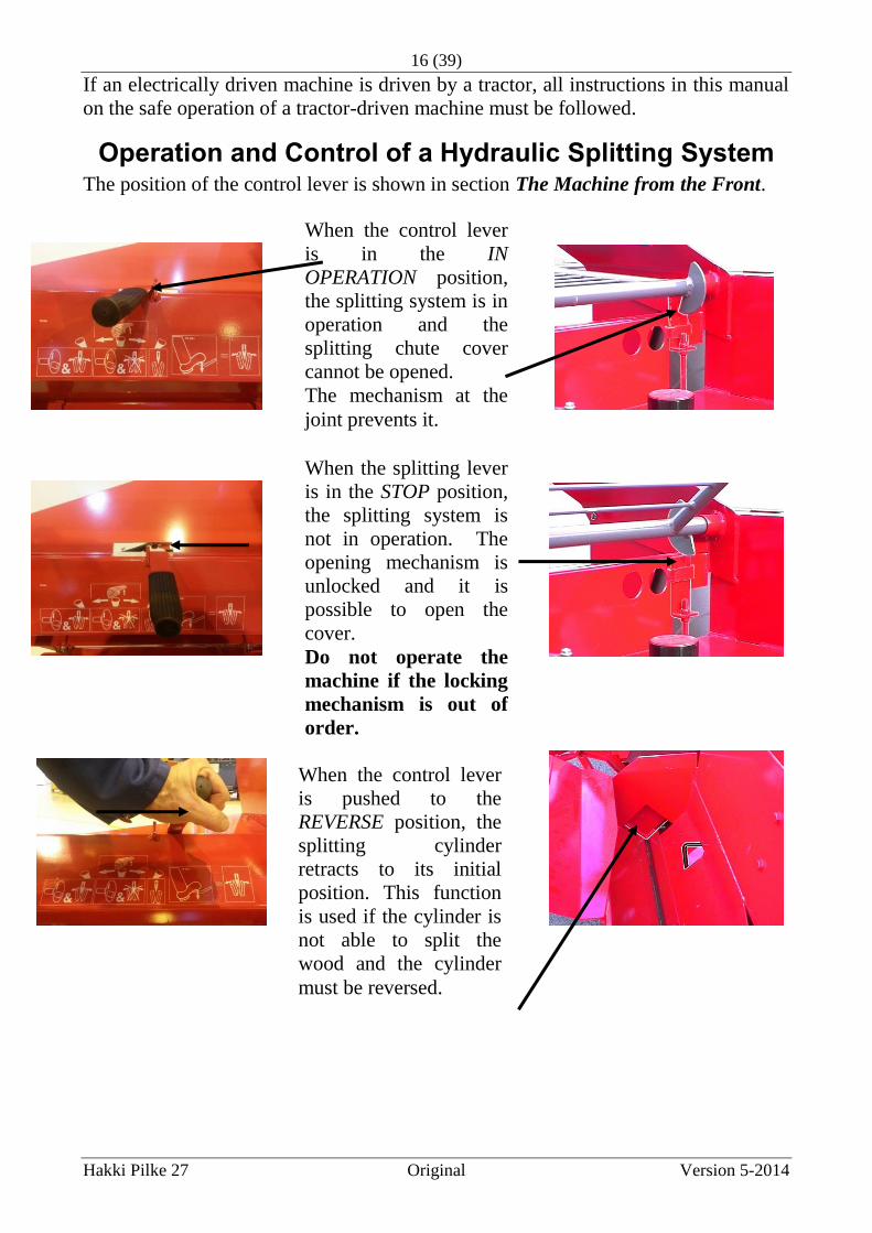
Operation and Control of a Hydraulic Splitting System The position of the control lever is shown in section The Machine from the Front.
When the control lever
is in the IN
OPERATION position,
the splitting system is in
operation and the
splitting chute cover
cannot be opened.
The mechanism at the
joint prevents it.
When the splitting lever
is in the STOP position,
the splitting system is
not in operation. The
opening mechanism is
unlocked and it is
possible to open the
cover.
Do not operate the
machine if the locking
mechanism is out of
order.
When the control lever
is pushed to the
REVERSE position, the
splitting cylinder
retracts to its initial
position. This function
is used if the cylinder is
not able to split the
wood and the cylinder
must be reversed.

17 (39)
Hakki Pilke 27 Original Version 5-2014
Starting the Splitting Movement
It is absolutely forbidden to start the splitting movement by activating the
automatic release lever with a hand, piece of wood or any other object.
Splitting Blade Adjustment, Dismounting and Reassembly
The splitting blade can be adjusted vertically inside the splitting chute. The size of
the wood determines the vertical position of the horizontal blade. The most
important thing is to ensure that the blade cross hits the wood in the middle, thus
splitting the wood into equally sized pieces. The adjustment is the same for blades
that split wood into 4 pieces and for blades that split wood into 6 pieces (optional).
Automatically: when the cut-
off wood hits the splitting
release lever in the splitting
chute.
By foot with the pedal: when test
running the machine or if automatic
splitting is out of order.
The adjustment lever is released from its locking by
pushing downwards. The vertical position of the blade
is adjusted by moving the lever sideways. When the
blade is in the desired position, the lever is placed in
the locking grooves on the machine frame.
The blade can be
released from its
adjustment lever and
removed by moving
the blade to its lowest
position.
Remove the blade for
sharpening or for
making firewood of
logs without splitting
them. Reassemble the
blade by carrying out
the process in reverse
order.

18 (39)
Hakki Pilke 27 Original Version 5-2014
Wood Length Adjustment
The length of the wood being split can be adjusted progressively from approx. 20 cm
to 55 cm using a mechanical wood measuring device attached to the splitting chute
cover (see the following figure). The location of the measuring device rod determines
the length of the wood being split. It is adjusted as follows:
Emergency Stop
The lower part of the machine has an emergency stop pedal at the operator's position.
If a dangerous situation occurs during machine operation, push the pedal down as
shown in the following figure.
1. Loosen the adjuster clamping
screw.
2. Move the measuring device rod to
the desired position and tighten
the clamping screw.
19 (39)
Hakki Pilke 27 Original Version 5-2014
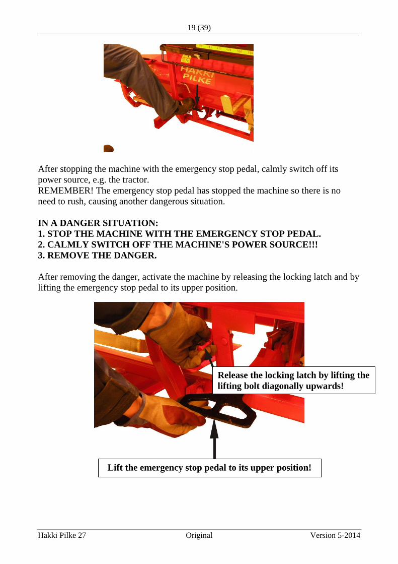
After stopping the machine with the emergency stop pedal, calmly switch off its
power source, e.g. the tractor.
REMEMBER! The emergency stop pedal has stopped the machine so there is no
need to rush, causing another dangerous situation.
IN A DANGER SITUATION:
1. STOP THE MACHINE WITH THE EMERGENCY STOP PEDAL.
2. CALMLY SWITCH OFF THE MACHINE'S POWER SOURCE!!!
3. REMOVE THE DANGER.
After removing the danger, activate the machine by releasing the locking latch and by
lifting the emergency stop pedal to its upper position.
Release the locking latch by lifting the
lifting bolt diagonally upwards!
Lift the emergency stop pedal to its upper position!

20 (39)
Hakki Pilke 27 Original Version 5-2014
Test Run
A test run must always be carried out before putting the machine into operation.
1. Make sure that the conveyor is in the work position and that the splitting chute
cover is down.
2. Start the tractor and let the engine idle.
3. Start the rotation of the tractor's power take-off by lifting the clutch pedal slowly
and smoothly. Let the machine run for a while.
4. For an electrically driven machine, let the machine run for a few minutes
depending on air temperature to warm up the oils before starting the test run.
5. Bring the splitting control lever to the In operation position.
6. Start the splitting movement with the pedal. Repeat the movement several times
and check that the machine is operating normally. Should there be any faults, repair
them.
7. Test the functions described in section Operation and Control of a Hydraulic
Splitting System.
If the functions are working correctly, you can start processing firewood as
instructed below.
Before Processing Firewood Do not begin to process firewood until you are fully familiar with the operating
principle of the machine and the safety precautions.
When processing firewood, you should:
- wear safe clothes:
- an outfit suitable for the weather conditions, with no hanging parts or
strings that may get caught in the wood or the machine and thus cause an
accident;
- safety boots with non-slip soles;
- gloves that give you a firm hold of the wood;
- appropriate face and eye shields and hearing protectors;
- arrange the work site so that:
- it is even and there is enough space for working;
- the trees are at an appropriate distance from the machine;
- familiarise yourself with safe working practices.

21 (39)
Hakki Pilke 27 Original Version 5-2014
Processing the Firewood You can start processing firewood as soon as you have familiarised yourself with all
safety precautions given above for the safe operation of the machine. Remember that
a test run must always be carried out before starting actual operation.
1. Adjust the revolutions of the tractor's power take-off to 410 rpm.
2. Place the wood measuring device rod in the desired position (see page 16).
3. Place the splitting blade in the desired vertical position (see page 15).
7. Calmly push the cradle forward and keep pushing it until it reaches its extreme
position. The cut wood remains in the trough formed by the cradle and the machine
frame.
4. Pull the splitting cradle to
its rear position. Note!
Always do this when
transferring wood for
cutting.
5. Lift the wood into the
cross-cut cradle. Observe
the proper lifting position
and mind your back (see
page 20)! 6. Transfer the wood against
the length limiter.
9. The cut wood drops
down into the splitting
chute and hits the
automatic splitting release
lever, which triggers the
hydraulic splitting
movement.
8. Calmly pull back the
cross-cut cradle.
22 (39)
Hakki Pilke 27 Original Version 5-2014
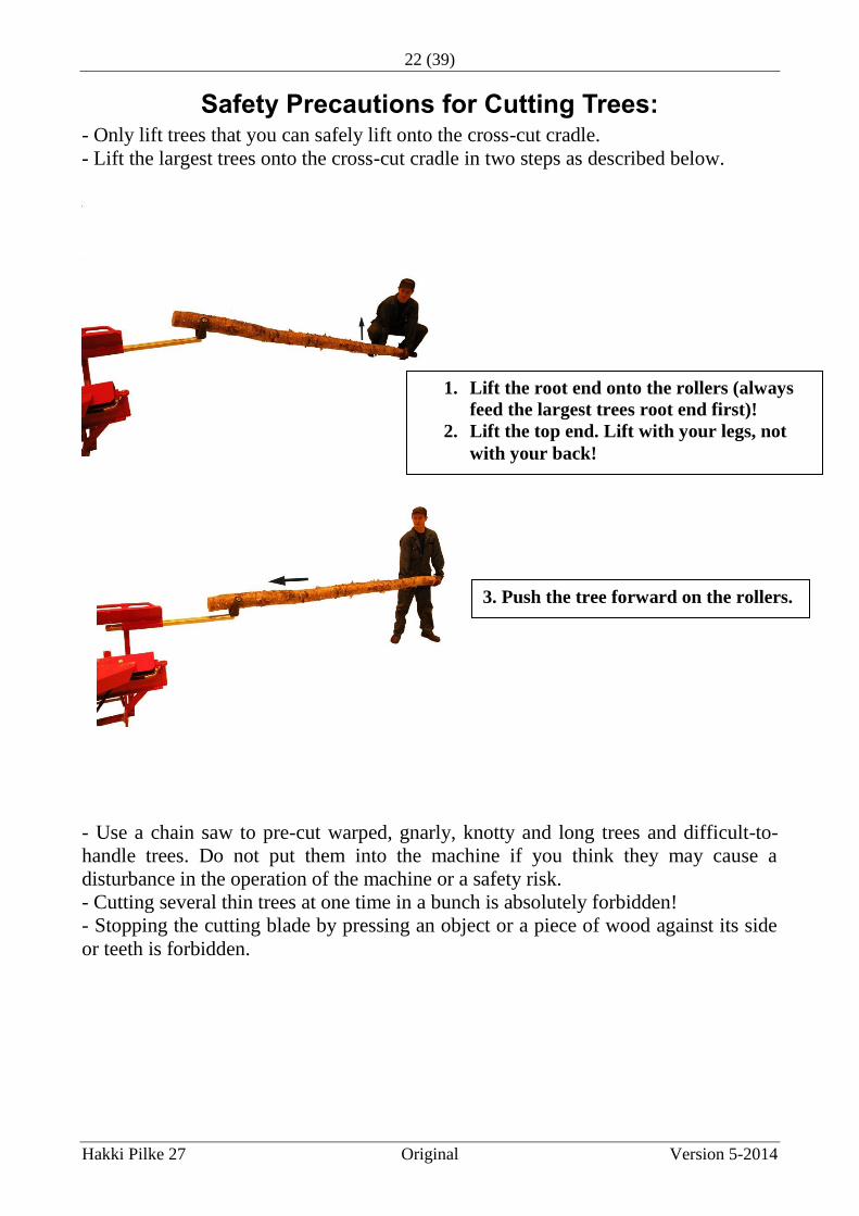
Safety Precautions for Cutting Trees: - Only lift trees that you can safely lift onto the cross-cut cradle.
- Lift the largest trees onto the cross-cut cradle in two steps as described below.
- Use a chain saw to pre-cut warped, gnarly, knotty and long trees and difficult-to-
handle trees. Do not put them into the machine if you think they may cause a
disturbance in the operation of the machine or a safety risk.
- Cutting several thin trees at one time in a bunch is absolutely forbidden!
- Stopping the cutting blade by pressing an object or a piece of wood against its side
or teeth is forbidden.
1. Lift the root end onto the rollers (always
feed the largest trees root end first)!
2. Lift the top end. Lift with your legs, not
with your back!
3. Push the tree forward on the rollers.

23 (39)
Hakki Pilke 27 Original Version 5-2014
- Support the tree being cut with a separate tree pusher as shown below.
- It is absolutely forbidden to use a cracked blade.
LOOK OUT for
blades that become
exposed from the
cover during cutting.
1. Press the tree against the table with
a tree pusher while pushing the tree
forward.
2. Support the pushing with your left
hand.

24 (39)
Hakki Pilke 27 Original Version 5-2014
Splitting the Last Cut Piece of Wood
4. Close the splitting chute cover and bring the splitting control lever to the In
operation position.
5. Start the splitting with the pedal.
Splitting a Split Piece of Wood Do as instructed above in section Splitting the Last Cut Piece of
Wood (page 22).
Removing Wood Caught in the Splitting Blade If the splitting cylinder does not have the power to split the wood intended for
splitting, do as follows:
1. Bring the splitting control lever to the Reverse position to return the splitting
cylinder to its initial position.
2. Leave the control lever in the Stop position.
3. Open the splitting chute cover using the handles.
Look out for the splitting blade during the removal!
4. After removing the wood, move it to the side or put it back into the splitting chute
and lower the splitting blade to its lowest position. The blade will then split the wood
only into two pieces, for which the cylinder has enough power.
5. Lower the splitting chute cover and move the splitting control lever to the In
operation position.
6. Start the splitting movement with the splitting pedal.
1. Bring the splitting
control lever to the Stop
position.
2. Open the splitting
chute cover using the
handles.
3. Drop the wood into
the splitting chute.
Cover lifting
handles

25 (39)
Hakki Pilke 27 Original Version 5-2014
Using the Conveyor Read the following sections of this manual:
- Bringing the conveyor into the transport position (page 9)
- Bringing the conveyor into the work position (page 7)
- Installing and adjusting the conveyor belt
- Adjusting the inclination of the conveyor (page 8)
In addition to the above-mentioned sections, the following must be observed:
- The work position of the conveyor must be adjusted to such an angle that the
conveyor will be able to take away all finished firewood.
- At its lowest position, the top end of the conveyor should be no lower than
approx. 1.8 m above the ground. If the conveyor is positioned lower than this, its
transmission from the drive belt to the conveyor will be prevented.
- The top end of the conveyor should be no higher than approx. 2.5 m above the
ground.
If the conveyor is at an angle steeper than this:
- pieces of wood may pile up behind the splitting blade in front of the
conveyor and longer pieces may hit the conveyor chute bottom, thus
damaging the conveyor;
- pieces of wood may tumble down from the top of the conveyor, thus
creating a dangerous situation.
When processing firewood ensure that:
- the firewood falling down from the conveyor hits the intended platform, cage, bed,
etc; - the platform, cage, bed, etc. is not filled with more firewood than it is intended to hold;
- the firewood load to be transported is structured in a way that no firewood can fall
from it during transportation;
- the distance between the top end of the conveyor and the firewood heap is no less
than approx. 50 cm, to avoid the jamming the conveyor belt due to accumulated
processed firewood;
- the conveyor is brought into the transport position even for short transfers (pages 7-
9);
- if the machine is moved to another place at the chopping site, ensure the machine or
conveyor does not hit the pile of chopped firewood;
- the lower end of the conveyor and splitting chute is kept free of wood waste.

26 (39)
Hakki Pilke 27 Original Version 5-2014
Finishing the Work 1. Make sure there is no firewood in the splitting chute or on the conveyor belt.
2. Stop the power take-off of the tractor.
3. Slightly lift the machine with the lifting mechanism of the tractor and move the
machine by approx. 0.5 m. Make sure that the conveyor does not hit anything.
4. Clean the machine, base and conveyor of wood waste.
5. Slowly lower the machine onto the ground and bring the conveyor into the
transport position (page 9).
Transferring the Machine When transferring the machine with a tractor:
- the conveyor must be in the transport position;
- the cross-cut cradle must be locked into the transport position as shown below;
- the necessary horizontal and vertical clearances required by the machine and
conveyor must be observed. Also check that there are no persons or animals around
the machine;
- the transportation must be carried out at such a low speed that no damage can occur
to the machine, tractor or anything along the route;
- no extra items can be carried on top of the machine and conveyor.
Machine Maintenance
Note! The machine must always be disconnected from the power source
(articulated shaft, electrical cable or both) before service!!!
27 (39)
Hakki Pilke 27 Original Version 5-2014
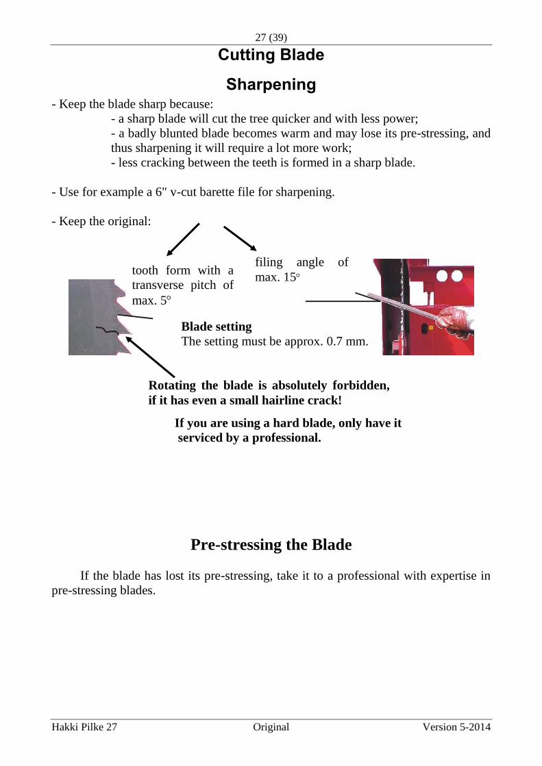
Cutting Blade
Sharpening - Keep the blade sharp because:
- a sharp blade will cut the tree quicker and with less power;
- a badly blunted blade becomes warm and may lose its pre-stressing, and
thus sharpening it will require a lot more work;
- less cracking between the teeth is formed in a sharp blade.
- Use for example a 6" v-cut barette file for sharpening.
- Keep the original:
If you are using a hard blade, only have it
serviced by a professional.
Pre-stressing the Blade
If the blade has lost its pre-stressing, take it to a professional with expertise in
pre-stressing blades.
tooth form with a
transverse pitch of
max. 5
filing angle of
max. 15
Blade setting
The setting must be approx. 0.7 mm.
Rotating the blade is absolutely forbidden,
if it has even a small hairline crack!

28 (39)
Hakki Pilke 27 Original Version 5-2014
Blade removal
Joint pin
1. Remove the upper
part of the blade cover
by removing its joint
pin.
2. Remove the two cradle
inclination adjustment nuts.
3. Fell down the cradle.

29 (39)
Hakki Pilke 27 Original Version 5-2014
Blade Attachment
6. Install the upper cover of the blade.
7. Lift the cross-cut cradle and put its two adjustment nuts in place.
8. Adjust the cradle to the correct angle (page 6).
Note! Always use the machine with blades complying with EN 847-
1:1997!
4. Lock the blade
in place by placing
an angular piece of
wood in the lower
part of the cutting
opening, between
the machine frame
and the teeth of the
blade.
6. Remove the nut, the flange
resting against the blade and the
wedge on the shaft.
5. Open the attachment
nut of the blade by
pressing the wrench
down.
7. Remove the blade through the slots in
the cover.
Remember to wear gloves when handling
the blade!
1. Put the blade in place through the same
slots through which you removed it.
2. Install the wedge on the shaft and then
install the blade support flange.
3. Turn the nut into position (left-handed
thread).
4. Lock the blade in place by placing an
angular piece of wood in the upper part of
the cutting opening, between the machine
frame and the teeth of the blade.
5. Tighten the blade attachment nut by lifting
the wrench.

30 (39)
Hakki Pilke 27 Original Version 5-2014
Installing the Conveyor Drive Belt
Note! When installing the belt, remove
the belt retaining bolt if necessary!
1. Remove the drive belt cover
from the machine frame by
opening the attachment bolt and
nut of the cover.
3. Place the belt on the pulley of
the angular gear.
4. Put the belt cover in place.
Make sure that the inner side of the cover
goes into the support groove on the
conveyor shaft.
2. Place the belt on the conveyor drive
pulley.
Make sure that the belt tensioning wheel
is pressing on the uppermost belt, on its
upper side.
5. Attach the cover to the machine frame
with a bolt and nut.

31 (39)
Hakki Pilke 27 Original Version 5-2014
Tightening Angular Gear Drive Belts in Model TR60
Tightening Angular Gear Drive Belts in Model TRS60
1. Open the locking of the belt
adjustment.
2. Open the locking of the adjustment nut.
3. Achieve the correct belt tightness by
turning the adjustment nut.
Belt tightness:
The belts should give way
approx. 15 to 20 mm when pushed
down between the pulleys.
4. Tighten the locking of the
adjustment.
Locking
Belt tightening (electric motor)
Belt tightening
Angular gear belt locking

32 (39)
Hakki Pilke 27 Original Version 5-2014
Machine Lubrication Protect yourself when handling lubricants to prevent them from causing problems to
your skin. When handling lubricants, make sure they do not end up in the
environment.
Apply grease on the points marked with this yellow symbol.
Hydraulic Oil
Splitting Mechanism
Change the hydraulic oil and filter at intervals of
approx. 500 operating hours or every other year.
The filling hole for hydraulic oil: there is a
dipstick in the cap, with a mark indicating the
correct oil level.
Hydraulic oil: normal hydraulic oil
E.g. Neste 32.
Hydraulic filter: cartridge type CR 50. Hydraulic oil tank: capacity 40 l.
Angular Gear The correct oil level:
In the horizontal position, oil
flows out through the filling hole.
Change the oil of angular
gear at intervals of
approx. 1,000 operating
hours.
Splitting control lever
The splitting mechanism is located in
front of the cross-cut cradle.
The mechanism can be adjusted by
removing the cover and its locking bolts.

33 (39)
Hakki Pilke 27 Original Version 5-2014
Operation
In the initial position,
the valve joint lever is
in its centre position.
When the cut wood hits the
sensor in the splitting chute,
the other end of the release
lever lifts up, and the joint
lever that controls the valve
is pushed to the right, thrust
by the spring.
The splitting movement
starts as the joint lever
moves to the right.
As the splitting cylinder/beam approaches the splitting
blade, the turning rod attached to the splitting beam will
swing the turning lever to its extreme right position.
Thus the valve joint lever goes to its extreme left
position, thrust by the spring.
Turning
lever
Turning rod
When the joint lever moves
to its extreme left position,
the splitting beam will
reverse. As the splitting
beam arrives at its initial
position, the turning rod
will swing the turning lever
to its extreme left position.
The splitting release lever
returns to its down
position during the
splitting movement.
With the turning lever in
its left position, the spring
pushes the joint lever to
the right.
However, the joint lever
stops against the splitting
release lever, which has
dropped down, and the
joint lever stays in its
centre position.
Joint lever

34 (39)
Hakki Pilke 27 Original Version 5-2014
Adjustments
Adjusting the Travel of the Splitting Beam A turning rod with stoppers is located under the splitting beam. The initial position
and the point of return of the splitting beam from near the splitting blade can be
adjusted by changing the position of these stoppers.
NOTE! Adjust the extreme positions of the splitting movement so that the
joint lever will work and make the splitting beam reverse from the
splitting blade all the way to its initial position.
Valve spool
direction
The joint lever, which controls the valve spool, must
be in its centre position at a 90° angle in relation to the
valve spool.
The centre position of the joint lever can be
adjusted with the bolt and locking nut at its side.
Stopper on the
cross-cut cradle
side
Stopper on the
splitting blade side
Splitting beam The stroke is
shortened
The stroke is
lengthened
Towards the
initial position
Protracted
into the splitting chute
35 (39)
Hakki Pilke 27 Original Version 5-2014
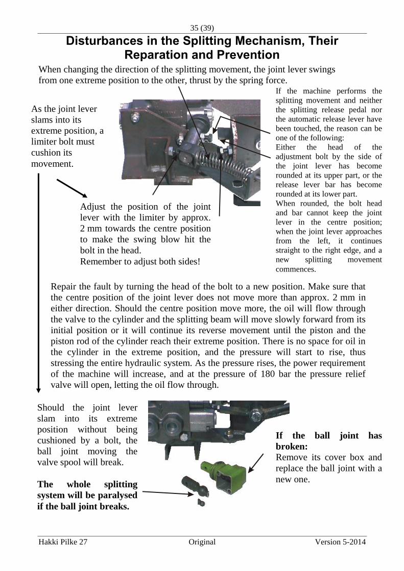
Disturbances in the Splitting Mechanism, Their Reparation and Prevention
When changing the direction of the splitting movement, the joint lever swings
from one extreme position to the other, thrust by the spring force.
Repair the fault by turning the head of the bolt to a new position. Make sure that
the centre position of the joint lever does not move more than approx. 2 mm in
either direction. Should the centre position move more, the oil will flow through
the valve to the cylinder and the splitting beam will move slowly forward from its
initial position or it will continue its reverse movement until the piston and the
piston rod of the cylinder reach their extreme position. There is no space for oil in
the cylinder in the extreme position, and the pressure will start to rise, thus
stressing the entire hydraulic system. As the pressure rises, the power requirement
of the machine will increase, and at the pressure of 180 bar the pressure relief
valve will open, letting the oil flow through.
If the machine performs the
splitting movement and neither
the splitting release pedal nor
the automatic release lever have
been touched, the reason can be
one of the following:
Either the head of the
adjustment bolt by the side of
the joint lever has become
rounded at its upper part, or the
release lever bar has become
rounded at its lower part.
When rounded, the bolt head
and bar cannot keep the joint
lever in the centre position;
when the joint lever approaches
from the left, it continues
straight to the right edge, and a
new splitting movement
commences.
As the joint lever
slams into its
extreme position, a
limiter bolt must
cushion its
movement.
Adjust the position of the joint
lever with the limiter by approx.
2 mm towards the centre position
to make the swing blow hit the
bolt in the head.
Remember to adjust both sides!
If the ball joint has
broken:
Remove its cover box and
replace the ball joint with a
new one.
Should the joint lever
slam into its extreme
position without being
cushioned by a bolt, the
ball joint moving the
valve spool will break.
The whole splitting
system will be paralysed
if the ball joint breaks.

36 (39)
Hakki Pilke 27 Original Version 5-2014
Hydraulic System Pressure Adjustment
Storing the Machine
The machine must be stored in a covered place where it is protected from collisions.
There is a pressure adjustment screw with a
locking nut at the joint lever end of the
valve: screwing inwards will increase the
pressure.
Max. pressure is 180 bar. Remember the
locking!

37 (39)
Hakki Pilke 27 Original Version 5-2014
Technical Specifications:
Power requirement 7.5 kW
Effect 3–6 m²/h
Cutting blade diameter 700 mm
Cylinder diameter / expulsive force 50 mm / 3.5 t
- optional 63 mm / 5.5 t
Flow of hydraulic 39 l/min
Volume of the oil tank / oil in tank 50 l / 40 l
Pressure of the hydraulic system 180 bar
Weight of the machine 490 kg (tr), 650 kg (combi)
Dimensions of the machine
- height 2,500 mm
- depth 800 mm
- width 2,500 mm
Noise level
Sound pressure level at the operator’s position 100 dB
Sound power level 110 dB
Maximum noise level at the operator’s position <130 dB (126 dB)
Weighted acceleration of hand vibration <2.5 m/s
VAT number FI 0550899-7
MAASELÄN KONE OY VALIMOTIE 1
85800 HAAPAJÄRVI, FINLAND
+358 (0) 8 7727300

38 (39)
Hakki Pilke 27 Original Version 5-2014
EU DECLARATION OF CONFORMITY OF MACHINE (Machine Directive 2006/42/EC, Appendix II A)
Manufacturer: Maaselän Kone Oy
Address: Valimotie 1, FI-85800 Haapajärvi, Finland
Name and address of the person who is authorized to collect technical file: Name: Tapio Aittokoski Address: Valimotie 1, FI-85800 Haapajärvi, Finland Declares that Hakki Pilke 27 Serial number:…………………………..
is compatible with relevant regulations of the Machine Directive (2006/42/EC)
is compatible with the following other EC-Directives: EMC-Directive 2004/108/EC and Low Voltage Directive 2006/95/EC
EC standards inspection certificate number: 31/2010 Institution approval number 0504 MTT Vakola Vakolantie 55 03400 Vihti, Finland Place, time: Haapajärvi 5.11.2012
Martti Kenttälä Managing Director
Guarantee terms “Guarantee terms come into force when you register your customership in the extranet service found on our website.”

39 (39)
Hakki Pilke 27 Original Version 5-2014
The guarantee is valid for the original buyer for 12 months, starting from the date of purchase, but for no more than 1 000 operating hours. In guarantee matters, always contact the machine’s seller before undertaking any procedures. A guarantee demand has to be issued to the seller immediately upon discovery of a defect. If the defect concerns a damaged part or component, please send a photograph of the damaged part or component to the seller, if possible, so the fault can be identified. When submitting a guarantee claim, the buyer must always include the type and serial number of the machine and present a receipt that includes the date of purchase. Guarantee claims must be submitted to an authorised retailer. The guarantee covers
Parts damaged in normal use due to faults in material or manufacture.
Reasonable expenses caused by repairing a fault in accordance with the agreement between the seller or buyer and manufacturer. Faulty parts will be replaced with new ones. A faulty part or parts replaced due to a material fault should be returned to the manufacturer through the retailer.
The guarantee does not cover
Damages caused by normal wear and tear (for example blades, mats and belts), improper use or use contrary to the instruction manual
Damages caused by negligence of maintenance or storage procedures detailed in the instruction manual
Damages caused during transport
Cutting blades, V-belts and oil, and normal adjustment, care, maintenance or cleaning procedures
Defects in a machine to which the buyer has carried out or commissioned structural or functional changes to the degree that the machine can no longer be considered equivalent to the original machine
Other potential costs or financial obligations resulting from the procedures mentioned above
Indirect costs
Travel costs resulting from guarantee repairs
The guarantee for parts replaced during the guarantee period of the machine expires at the same time as the machine’s guarantee
The guarantee is void if the ownership of the machine is transferred to a third party during the guarantee period
The guarantee is void if any of the machine’s seals have been broken If a fault or defect reported by the customer is found to not be covered by the guarantee, the manufacturer has the right to charge the customer for the pinpointing and possible repair of the fault or defect in accordance with the manufacturer's current price list. This guarantee certificate indicates our responsibilities and obligations in full and it excludes all other responsibilities.


![Hakki Pilke BigX50 - JSWoodhouse.com Pilke BigX50 Parts Manual.pdf · Lesjofors 2 28 47666_Optical measuring device with cover 1 29 97557_DF10,3A[XXL]17SLP 1 30 95421_Pin limit switch](https://img.dokumen.tips/doc/110x75/60bea395dbf2753f9518f9ef/hakki-pilke-bigx50-pilke-bigx50-parts-manualpdf-lesjofors-2-28-47666optical.jpg)