Embed Size (px)
Citation preview

7/27/2019 English for students
http://slidepdf.com/reader/full/english-for-students 1/42
Федеральное агентство по образованию
Государственное образовательное учреждение высшего профессионального образования
Ухтинский государственный технический университет
(УГТУ)
Английский язык
для студентов II курса
специальности МОН
Часть 2
Методические указания
Ухта 2009

7/27/2019 English for students
http://slidepdf.com/reader/full/english-for-students 2/42
УДК 802.0 (075)
Е 64
Енцова, В.И.Английский язык для студентов II курса специальности МОН [Текст]: метод.
указания. В 2 ч. Ч. 2 / В.И. Енцова. – Ухта: УГТУ, 2009. – 42 с.
Методические указания состоят из четырёх разделов, каждый из которых со-
держит современный терминологический словарь, тематические тексты по оборудо-
ванию нефтегазовой промышленности.
Комплекс упражнений направлен на расширение навыков устной речи в рам-
ках профессиональной деятельности.
Все упражнения способствуют расширению лексического запаса, а также по-вторению и закреплению грамматических оборотов и явлений, характерных для
письменной речи, что развивает навыки обучаемых работать со специальными тек-
стами самостоятельно.
Наличие дополнительных текстов даёт возможность обучаемым совершенст-
вовать навыки перевода и аннотирования.
Данные методические указания соответствуют рабочей учебной программе и
рекомендуются к использованию в учебном процессе.
Методические указания рассмотрены и одобрены на заседании кафедры
17 июня 2009 года, протокол № 9.
Рецензент: Старший преподаватель кафедры иностранных языков Л.В. Салайда.
План 2009 г., позиция 298.
Компьютерный набор. Подписано в печать 07.09.2009 г.
Объем 42 с. Тираж 50 экз. Заказ № 234.
© Ухтинский государственный технический университет, 2009
169300, Республика Коми, г. Ухта, ул. Первомайская 13.
Отдел оперативной полиграфии УГТУ.
169300, Республика Коми, г. Ухта, ул. Октябрьская 13.
7/27/2019 English for students
http://slidepdf.com/reader/full/english-for-students 3/42
3
Unit 1. Artificial lift
1. Study the words and word combinations:
1. сomplete – завершить 46. bridle – канатная подвеска
2. intermediate (production) casing – про-
межуточная (эксплутационная) обсадная
колонна
47. sucker-rod guide – направляющая ко-
лонны штанг
3. perforated (open-holed) completion – за-
вершение скважины перфорацией (при
необсаженном забое)
48. sucker-rod coupling – штанговый со-
единительный фланец
4. shoot – простреливать 49. polished rod – устьевый (полирован-
ный) шток
5.shaped-explosive charge – кумулятив-
ный заряд
50. stuffing box – сальник
6. tubing (tubing string) – насосно-ком-
прессорные трубы = НКТ (колонна НКТ)
51. tеe – тройник
7. casing-tubing annulus – затрубное про-
странство между обсадной колонной и
НКТ
52. wrench (wrench flat) – гаечный ключ
(срез под ключ)
8. workover – ремонт, ремонтные работы 53. male (female) thread – наружная
(внутренняя) резьба
9. crucifix type – крестообразного типа 54. tapered – конический
10. Christmas tree – фонтанная арматура,
оборудование устья скважины
55. working barrel – цилиндр глубинного
насоса
11. pressure gauge – манометр 56. travelling (standing) valve – нагнета-тельный (всасывающий) клапан
12. master (swab, flow wing) valve – ство-
ловая (центральная, отводящая = выкид-
ная) заглушка
57. plunger – плунжер
13. kill wing valve – клапан глушения на
отводящей линии (струне)
58. seat – седло
14. output = production rate = yield –
дебит, добыча
59. cage – клетка
15. hydraulically actuated – приводимый в действие жидкостью
60. upstroke (downstroke) – ход вверх (вниз)
16. manually operated – управляемый
вручную
61. anchor – якорь, анкер
17. single wing (double wing) tree – фон-
танная арматура с одинарным (двойным
отводом)
62. rear – задний
18. corrosion inhibitor – ингибитор
коррозии
63. counterbalance – противовес
19. hydrate formation – водный пласт 64. fulcrum – точка опоры 20. primary means – основное средство 65. conventional unit (class I lever system) –
двуплечный кривошипный станок-качалка
7/27/2019 English for students
http://slidepdf.com/reader/full/english-for-students 4/42
4
21. wireline – стальной канат 66. Lufkin Mark II – одноплечный криво-
шипный станок-качалка фирмы “Lufkin”
22. artificial lift – механизированная (на-
сосно-компрессорная) эксплуатация
67. air-balanced system – одноплечный
станок-качалка с пневматическим проти-
вовесом
23. multiple flanged joints – многочислен-ные фланцевые соединения
68. offshore platform – морская платформа
24. insert (install, mount) – вставлять (ус-
танавливать, монтировать)
69. deviated (crooked) well (hole) – откло-
ненная, искривлённая скважина
25. downhole pump – погружной (глубин-
ный) насос
70. mandrel (side-pocket mandrel) – камера
(эксцентричная, т.е. смещённая относи-
тельно оси, камера с карманом)
26. beam-type pumper – станок-качалка с
двуплечным балансиром
71. relatively/respectively –
соответственно/относительно
27. gas lift – газлифт 72. excessive – избыточный, чрезмерный 28. electric submersible pump (ESP) –
электрический глубинный (погружной)
насос
73. intermittently – прерывисто (с пере-
рывом)
29. hydraulic/jet pump – гидропоршневой
/струйный насос
74. blade = impeller – рабочее колесо цен-
тробежного насоса
30. sucker-rod (sucker-rod string) – насос-
ная штанга (колонна насосных шланг)
75. diffuser – рассеиватель
31. sucker-rod pump (walking beam sucker-
rod system) – штанговый насос (балан-сирный станок-качалка)
76. volute chamber – спиральная камера
32. tubing (casing) pump – трубный
(обсадной) насос
77. axis(pl. axes) – ось, оси
33. centrifugal pump – центробежный
насос
78. deploy – развёртывать
34. gear reducer – редуктор, редукцион-
ная зубчатая передача
79. trigger – запускать
35. crank – кривошип, коленчатое
соединение
80. armored cable – бронированный (ар-
мированный) кабель 36. walking beam – балансир насосной
установки
81. strap – прикреплять
37. concrete base – бетонная опора 82. jet nozzle – струйная гидромониторная
насадка
38. Samson post – стойка балансира 83. power fluid – рабочая жидкость
39. pitman (pitman – crank assembly) – ша-
тун (шатунно-кривошипный механизм)
84. enhance – увеличивать
40. cross bar = equalizer – траверса 85. versatile – изменчивый, многосторон-
ний 41. reciprocating motion – возвратно-
поступательное движение
86. CO2 = carbon dioxide – углекислый газ
7/27/2019 English for students
http://slidepdf.com/reader/full/english-for-students 5/42
5
42. pivot – качаться 87. H2S = hydrogen sulphide – сернистый
газ, сероводород
43. impart = convey – передавать 88 velocity = rate – скорость
44. lever – рычаг 89. eliminate – исключать, устранять
45. horsehead – головка балансира 90. bpd – barrel per day
2. Read the text and do the exercises: 1. To produce oil it requires carrying out some activities in the definite order such
as: to drill the well, test and complete it as a producer. Completing the well means setting
a number of casing strings (a conductor - a surface casing, intermediate and productionones), cementing them; completing the bottom of the hole either with open-holed or perfo-
rated methods (the latter is followed by shooting the casing with shaped -explosive
charges), and lowering tubing. Installing tubing helps to protect casing from corrosion, the
casing is hard to remove during a workover. For gas and flowing oil wells a series of fit-
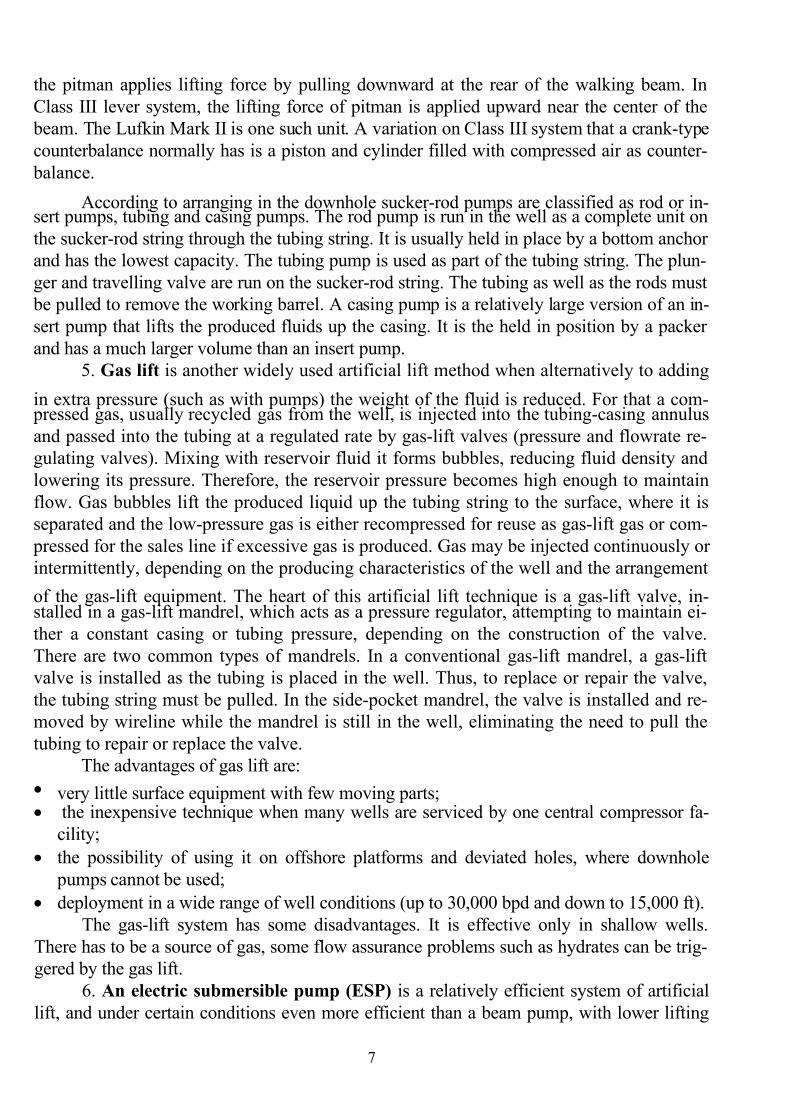
tings, valves and gauges (a Christmas tree) is bolted to the wellhead to control flow.
2. A typical surface tree has four valves, normally arranged in a crucifix type pat-tern. The two lower valves are called the master valves (upper and lower respectively)
because they lie in the well fluid flow path to the surface. The lower master valve is nor-
mally manually operated, while the upper master valve is often hydraulically actuated and
is a primary means of well control.
The right-hand valve is called the flow wing valve or the production wing valve,
because it is turned to regulate flow through the flowline. It is hydraulically actuated. One
producing zone in the well requires a single wing tree; two producing zones - a double
wing tree with two wings on opposite sides.
The left-hand valve, the kill wing valve, is only used for injection of fluids such ascorrosion inhibitors or methanol to prevent hydrate formation. It is typically manually op-
erated.
The valve at the top is called the swab valve, and it lies in the path used for opening
the well for wireline and other equipment being lowered during a workover and other well
interventions. This valve is usually manually operated. A pressure gauge at the top of the
tree is measured tubing pressure. Most Christmas trees are machined out of a solid block
of metal rather than made from multiple flanged joints and the term is properly called the
wellhead control equipment.
3. Most oil wells, however, have insufficient reservoir pressure to lift the liquid to
the surface, and artificial lift is needed. It often used in naturally flowing wells (which
don’t technically need it) to increase the flow rate above what would flow naturally. When
this happens, the Christmas tree has to be removed, and an artificial lift system is installed
in a process called putting the well on pump. The pump is designed to be inserted into the
tubing of a well and its main purpose is to gather fluids from beneath and lift them to the
surface. In the USA 82% artificially- lifted wells use beam-type pumper, 10% ones em-
ploy gas lift, 4% and 2% the wells use respectively electric submersible and hydraulic
pumps.
4. The most recognized type of pumps is a sucker-rod pump (or a walking beam
sucker-rod system), widely used in low-rate wells with the output of from 30-50 up to 200 m3
per day (10’s-100’s bpd). The system consists of the surface and downhole components. A

7/27/2019 English for students
http://slidepdf.com/reader/full/english-for-students 6/42
6
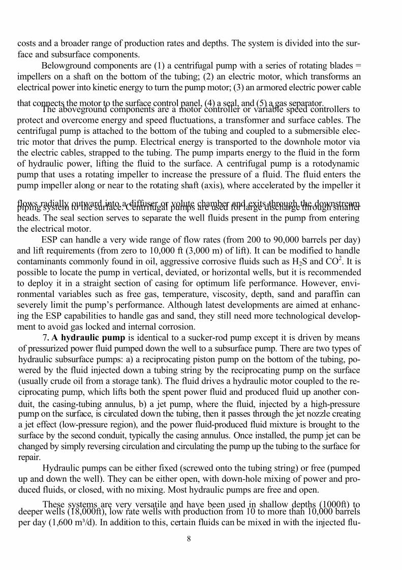
surface pumping unit drives a downhole pump assembly. An electric motor drives the gear
reducer (decreases the rotational speed), which rotates a crank. The pitman (a steel arm or
two steel arms with a cross bar) - crank assembly converts the rotary motion into a reci-
procating motion and imparts it through the attached walking beam (mounted on a concrete base, it pivots up and down on bearings on the top of a Samson post and acts like the lever)
to the sucker-rod string and to a downhole pump assembly.The sucker-rod string is connected to the walking beam by means of a horsehead (it
keeps the pull on the sucker-rod string vertical), a bridle (a wire rope), a steel bar (a carrier),a polished rod and a stuffing box (a sealing container or "O" ring seals around the polished
rod, filled with flexible rubber). The sucker-rod string runs down the tubing string to the
downhole pump, and it consists of sucker-rods of 1/2 and 1 1/4 in. (1 to 3 cm) in diameter
and 25 ft (7 1/2 m) long with male threads on the both ends. They are connected together
with a short, steel cylinder with female threads on the inside called sucker-rod couplings.
Flat areas (wrench flats) allow a wrench to grip the coupling without harming it. The suck-
er-rod string is kept central in the tubing string by sucker-rod guides made of rubber, plas-tic, or metal. Reservoir fluids flow up the tubing through slots in the guides. Shorter lengths
of sucker-rods (pony rods) can be used to adjust the length of the sucker-rod string. The
string can be either untapered (all one diameter) or tapered, with a decrease in rod diameter
down the well.
A sucker-rod pump contains a plunger and valve assembly to convert the reciprocat-
ing motion to vertical fluid movement, creating a suction that draws oil up through the well.
Rod pumps are large cylinders with both fixed and moveable elements inside. The
most important components are: the working barrel, valves (travelling and standing) and the
plunger (piston). It also has another 18 to 30 components which are called "fittings". The
travelling valve moves up and down while the standing valve remains stationary. Both
valves consist of a ball, a seat (a plate with a hole) and a cage to hold the ball over the seat.
The steel ball allows the oil to flow up but not back down through the valve. Fluid flowing
upward lifts the ball off the seat and opens the valve. Fluid can’t flow down because gravity
holds the ball in the seat. As the sucker-rods start the upstroke, they lift the plunger and tra-
velling valve, creating a reduced pressure below it inside the working barrel. During this
part of the cycle, the travelling valve is closed and the standing one is open. This reduced
pressure within the working barrel allows fluid to flow from the formation and the casing-
tubing annulus through the anchor, the standing valve and into the working barrel. On the
downstroke, the travelling valve opens and the standing valve closes, allowing fluid in the barrel to move up into the tubing above the travelling valve. Production at the surface may
appear continuous, but in reality it only occurs on the upstroke of the pump. There are
commonly 10 to 20 strokes per minute.
Conventional pumping units in smaller sizes can have the counterbalance weights (to
balance the weight of the sucker-rod string) mounted at the rear of the walking beam (beam-
balanced units) or mounted on the crank arm (crank-balanced units: usually have two rotat-
ing counterweights of steel, located on both sides of the rotary crank). Larger conventional
units are all crank-balanced.
The beam pumping units are classified according to the position of the fulcrum (ClassI or Class III) and counterbalance weights (air, crank or beam). In Class I lever system (also
called conventional pumping unit), the fulcrum is near the center of the walking beam and
7/27/2019 English for students
http://slidepdf.com/reader/full/english-for-students 7/42
7
the pitman applies lifting force by pulling downward at the rear of the walking beam. In
Class III lever system, the lifting force of pitman is applied upward near the center of the
beam. The Lufkin Mark II is one such unit. A variation on Class III system that a crank-type
counterbalance normally has is a piston and cylinder filled with compressed air as counter-
balance.
According to arranging in the downhole sucker-rod pumps are classified as rod or in-sert pumps, tubing and casing pumps. The rod pump is run in the well as a complete unit on
the sucker-rod string through the tubing string. It is usually held in place by a bottom anchor
and has the lowest capacity. The tubing pump is used as part of the tubing string. The plun-
ger and travelling valve are run on the sucker-rod string. The tubing as well as the rods must
be pulled to remove the working barrel. A casing pump is a relatively large version of an in-
sert pump that lifts the produced fluids up the casing. It is the held in position by a packer
and has a much larger volume than an insert pump.
5. Gas lift is another widely used artificial lift method when alternatively to adding
in extra pressure (such as with pumps) the weight of the fluid is reduced. For that a com- pressed gas, usually recycled gas from the well, is injected into the tubing-casing annulus
and passed into the tubing at a regulated rate by gas-lift valves (pressure and flowrate re-
gulating valves). Mixing with reservoir fluid it forms bubbles, reducing fluid density and
lowering its pressure. Therefore, the reservoir pressure becomes high enough to maintain
flow. Gas bubbles lift the produced liquid up the tubing string to the surface, where it is
separated and the low-pressure gas is either recompressed for reuse as gas-lift gas or com-
pressed for the sales line if excessive gas is produced. Gas may be injected continuously or
intermittently, depending on the producing characteristics of the well and the arrangement
of the gas-lift equipment. The heart of this artificial lift technique is a gas-lift valve, in-stalled in a gas-lift mandrel, which acts as a pressure regulator, attempting to maintain ei-
ther a constant casing or tubing pressure, depending on the construction of the valve.
There are two common types of mandrels. In a conventional gas-lift mandrel, a gas-lift
valve is installed as the tubing is placed in the well. Thus, to replace or repair the valve,
the tubing string must be pulled. In the side-pocket mandrel, the valve is installed and re-
moved by wireline while the mandrel is still in the well, eliminating the need to pull the
tubing to repair or replace the valve.
The advantages of gas lift are:
• very little surface equipment with few moving parts;• the inexpensive technique when many wells are serviced by one central compressor fa-
cility;
• the possibility of using it on offshore platforms and deviated holes, where downhole
pumps cannot be used;
• deployment in a wide range of well conditions (up to 30,000 bpd and down to 15,000 ft).
The gas-lift system has some disadvantages. It is effective only in shallow wells.
There has to be a source of gas, some flow assurance problems such as hydrates can be trig-
gered by the gas lift.
6. An electric submersible pump (ESP) is a relatively efficient system of artificial
lift, and under certain conditions even more efficient than a beam pump, with lower lifting
7/27/2019 English for students
http://slidepdf.com/reader/full/english-for-students 8/42
8
costs and a broader range of production rates and depths. The system is divided into the sur-
face and subsurface components.
Belowground components are (1) a centrifugal pump with a series of rotating blades =
impellers on a shaft on the bottom of the tubing; (2) an electric motor, which transforms an
electrical power into kinetic energy to turn the pump motor; (3) an armored electric power cable
that connects the motor to the surface control panel, (4) a seal, and (5) a gas separator.The aboveground components are a motor controller or variable speed controllers to
protect and overcome energy and speed fluctuations, a transformer and surface cables. The
centrifugal pump is attached to the bottom of the tubing and coupled to a submersible elec-
tric motor that drives the pump. Electrical energy is transported to the downhole motor via
the electric cables, strapped to the tubing. The pump imparts energy to the fluid in the form
of hydraulic power, lifting the fluid to the surface. A centrifugal pump is a rotodynamic
pump that uses a rotating impeller to increase the pressure of a fluid. The fluid enters the
pump impeller along or near to the rotating shaft (axis), where accelerated by the impeller it
flows radially outward into a diffuser or volute chamber and exits through the downstream piping system to the surface. Centrifugal pumps are used for large discharge through smallerheads. The seal section serves to separate the well fluids present in the pump from entering
the electrical motor.
ESP can handle a very wide range of flow rates (from 200 to 90,000 barrels per day)
and lift requirements (from zero to 10,000 ft (3,000 m) of lift). It can be modified to handlecontaminants commonly found in oil, aggressive corrosive fluids such as H2S and CO2. It is
possible to locate the pump in vertical, deviated, or horizontal wells, but it is recommended
to deploy it in a straight section of casing for optimum life performance. However, envi-
ronmental variables such as free gas, temperature, viscosity, depth, sand and paraffin canseverely limit the pump’s performance. Although latest developments are aimed at enhanc-
ing the ESP capabilities to handle gas and sand, they still need more technological develop-
ment to avoid gas locked and internal corrosion.
7. A hydraulic pump is identical to a sucker-rod pump except it is driven by means
of pressurized power fluid pumped down the well to a subsurface pump. There are two types of
hydraulic subsurface pumps: a) a reciprocating piston pump on the bottom of the tubing, po-
wered by the fluid injected down a tubing string by the reciprocating pump on the surface
(usually crude oil from a storage tank). The fluid drives a hydraulic motor coupled to the re-
ciprocating pump, which lifts both the spent power fluid and produced fluid up another con-
duit, the casing-tubing annulus, b) a jet pump, where the fluid, injected by a high-pressure pump on the surface, is circulated down the tubing, then it passes through the jet nozzle creating
a jet effect (low-pressure region), and the power fluid-produced fluid mixture is brought to the
surface by the second conduit, typically the casing annulus. Оnсe installed, the pump jet can be
changed by simply reversing circulation and circulating the pump up the tubing to the surface for
repair.
Hydraulic pumps can be either fixed (screwed onto the tubing string) or free (pumped
up and down the well). They can be either open, with down-hole mixing of power and pro-
duced fluids, or closed, with no mixing. Most hydraulic pumps are free and open.
These systems are very versatile and have been used in shallow depths (1000ft) todeeper wells (18,000ft), low rate wells with production from 10 to more than 10,000 barrels
per day (1,600 m³/d). In addition to this, certain fluids can be mixed in with the injected flu-
7/27/2019 English for students
http://slidepdf.com/reader/full/english-for-students 9/42
9
id to help deal or control with corrosion, paraffin and emulsion problems. They are also
suitable for wells where conventional pumps such as the rod pumps are not possible due to
crooked or deviated wells. These systems have also some disadvantages. They are sensitive to
solids and have high surface horsepower requirements. It is the least efficient lift method.
Ex. 1. Tell the groupmates if the statements are true (T) or False (F):
1. Completing a well means testing it in order to finding out its production capacity. (T/F)2. The wellhead only gas wells is equipped with a Christmas tree. (T/F)
3. A Christmas tree is correctly called well control equipment. (T/F)
4. A sucker-rod pump is the most common one used for artificially-lifted wells. (T/F)
5. A sucker-rod string converts a rotary motion of a walking beam into a reciprocating mo-
tion of a downhole pump. (T/F)
6. During the upstroke of sucker-rods and the plunger the valve is open and the one is
closed. (T/F)
7. Both travelling and standing valves consist of a ball and a cage. (T/F)
8.
Sucker-rods have male threads on the both ends. (T/F)9. Large conventional units are all crank-balanced. (T/F)
10. A casing pump has a smaller volume then a sucker-rod one. (T/F)
11. The gas lift valve injects compressed gas into the well to reestablish pressure, making it
produce. (T/F)
12. Gas lift can be only continuous. (T/F)
13. The electric submersible pump applies artificial lift by spinning the impellers on the
pump shaft, putting pressure on the surrounding fluids and forcing them to the surface.
(T/F)
14. Hydraulic pumps are useful for deviated wells. (T/F)Ex. 2. A Christmas tree. Match the figurers with the equipment presented:
Fig. 1-1 an electrical submersible pump (ESP)
Fig. 1-2 gas lift
Fig. 1-3 a Christmas tree
Fig. 1-5 a sucker-rod pump
Fig. 1-1 Fig. 1-2 Fig. 1-3
7/27/2019 English for students
http://slidepdf.com/reader/full/english-for-students 10/42
10
m
m h
h-m
h
h h
m-h
Fig. 1-4 Fig. 1-5
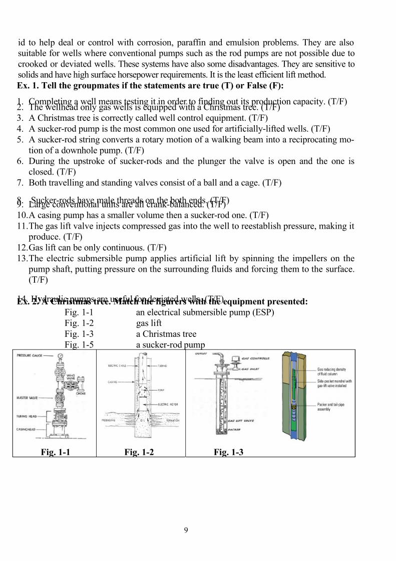
Ex. 3. A Christmas tree. Indicate (rely on the figure): missing valves;
all possible trunk and wing valves;
the way they are operated:manually (m) or hydraulically (h) -
the variant ″a″ or ″ b″
a b Ex. 4. A sucker-rod pumping system.
a) Define the components of the following systems and the motion they convey:
The system Components The motion the system conveys
converts): a) rotary, b)reciprocating
c) vertical fluid movement, d) no
1. Surface
2. Downhole
3. Sucker-rod string (& connectors)
4. Sucker-rod pump
5. Valves
b) For the valves choose the right
variant: open (O) or closed (C),
and explain your choice.
Valves travelling
standing
Upstroke Downstroke Why O/C
O/C
7/27/2019 English for students
http://slidepdf.com/reader/full/english-for-students 11/42
11
c) Fig. 1-4. Complete the sentences:
1. The presented classification is based on both (1)_ and (2)_ .
2. Class I lever-conventional unit has (3)_ lever(s) on the (4)_ beam.
3. (5)-levered unit is employed in Class III.4. The difference between two variants of Class III is in (6)_.
Ex. 5. Gas lift.a) Place the questions in the logical text order and answer them:
1. What mandrel is more profitable in use: conventional or side-pocket? Why?2. How is gas utilized on the surface?
3. Why is the gas- reservoir fluid mixture lifted?
4. Is the objective of gas lift to increase downhole pressure or to reduce produced fluid
weight?
5. The main advantage of gas lift is that it’s employed little surface equipment with few
moving parts, isn’t it?
6. What gas and where is it usually injected?7. Where is the gas- reservoir fluid mixture passed by a gas-lift valve?
b) Ask questions to the sentences:
1. The injected gas, typically recycled gas from the well, reestablishes (reduces) the pres-
sure on the bottom of the well by decreasing the viscosity of the fluids in the well.
2. This, in turn, encourages the fluids to flow more easily to the surface.
3. With very few surface units gas lift is the optimal choice for offshore applications.
Ex. 6. An electric submersible pump (ESP).
a. Match two halves (A with B) to complete the sentences:
A B
1 The whole system is installed a. the pump is composed of several impel-
lers, or blades, that move the fluids withinthe well.
2. Mass producers, electric submersible
pumps
b. drives the coupled centrifugal pump,
which causes reservoir fluid to flow to the
surface.
3. Connected to a long electric motor, c. connecting the pump to a surface source
of electricity.
4. An electric cable runs the length of the
well,
d. can lift more than 25,000 barrels of flu-
ids per day.
5. A submersible electric motor e. at the bottom of the tubing string.
b) 1. Put the numbers in the order to present the work of an ESP.
2. Tell us how efficient this system of artificial lift is.
Ex. 7. a) Make up the scheme how two types of hydraulic pumps work. Use words
given below (they are in a mixed order):
a hydraulic pump a jet pump to lift both the spent power fluid and produced fluid, the surface pump,
to pass through the jet nozzle, a subsurface hydraulic motor,
a high-pressure pump on the surface, a reciprocating pump,the mixture is brought to the surface by the casing annulus.
7/27/2019 English for students
http://slidepdf.com/reader/full/english-for-students 12/42
12
b) What is the set of applications for the hydraulic pumps? Why are they the least efficient
in artificial lift? (%)
Ex. 8. There are the descriptions of different artificial lift methods. Read the abstracts
and indicate the method:
1. The most common type of artificial lift pump system applied is the pumping, which en-
gages the equipment on and below the surface to increase pressure and push oil to the sur-face. Consisting of the string and the pump, the beam pumps are the familiar jack pumps
seen on onshore oil wells. (_)2. Both the surface and subsurface hydraulic pumps are powered by power oil, or clean oil
that has been previously lifted from the well. The surface pump sends the power oil
through the tubing string to the subsurface hydraulic pump installed at the bottom of the
tubing string, the reservoir fluids are then sent up a second parallel tubing string to the sur-
face. (_)
3. The compressed gas is injected down the casing-tubing annulus, entering the well at
numerous entry points called gas-lift valves. As the gas enters the tubing at these differentstages, it forms bubbles, lightens the fluids, lowers the pressure and the mixture is lifted to
the surface. (_)
4. The system employs a centrifugal pump below the level of the reservoir fluids. Con-
nected to a long electric motor, the pump is composed of several impellers, or blades, that
move the fluids within the well. The whole system is installed at the bottom of the tubing
string. An electric cable runs the length of the well, connecting the pump to a surface
source of electricity. (_)
Ex. 9. Make the annotation of the main text to present the key points of the nume-
rated abstracts. The set of phrases for an annotation at the end of the manual will help
you.
3. Grammar exercises.
Ex. 1. a) Read the sentences and pay attention to the underlined gerund (which is used after
all prepositions, the special verbs and the phrases).
a) A gas-lift system provides production energy by injecting gas into the production fluid
column, thereby reducing the hydrostatic pressure and enabling improved reservoir produc-
tion. The equipment must go through a number of tests before being installed. Fluid pound is
a problem caused by the produced liquid being pumped faster than it is flowing into the well.
After gas being entered (or having been entered) the pump, it can be damaged. Gas accumu-
lates in the pump and prevents it from working. It’s worth mentioning that gas lock is the ex-treme case of fluid pound
b) Find the gerund in the first abstract of the main text.
To produce oil it requires carrying out some activities in the definite order such as: to drill
the well, test and complete it as a producer. Completing the well means setting a number of
casing strings (a conductor - a surface casing, intermediate and production ones), cementing
them; completing the bottom of the hole either with open-holed or perforated methods (the
latter is followed by shooting the casing with shaped -explosive charges), and lowering
tubing. Installing tubing helps to protect casing from corrosion, the casing is hard to re-
move during a workover.
7/27/2019 English for students
http://slidepdf.com/reader/full/english-for-students 13/42
13
c) Transform the sentences to use gerund after the words. Use the preposition, where
necessary:
1. Other types of commonly used pumps are Electric
Submersible Pump (ESP's), Progressing-Cavity
pumps (PCP's), Jet Pumps, and Hydraulic Pumps.
1. Possibility
2. These pump systems must be installed in the well
downhole.
2. Require (need)
3. They also include a ground-level power-supply de-
vice that can be mechanical (rod pumps and PCP's),
electrical (ESP's), or even hydraulic (jet and hydraulic
pumps).
3. Can’t help
4. A progressing cavity pump, PCP, is also widely
applied in the oil industry.
4.Opportunity
5. The PCP consists of a stator and a rotor. 5. Need, install
6. The rotor is rotated using either a top-side motor or
a bottomhole motor.
6. be engaged
7. The rotation created sequential cavities and the pro-
duced fluids are pushed to surface.
7. Result
8. The PCP is a flexible system with a wide range of
applications in terms of rate (up to 5,000 bpd and6,000 ft).
8. Get used to, provide
9. They offer outstanding resistance to abrasives and
solids, but they are restricted to setting depths and
temperatures.
9. Rely/aim, object
10. Some components of the produced fluids like
aromatics can also deteriorate (get worse) the stator’s
elastomer.
10. Accuse
4. Translate the text from Russian into English and make up its plan:
Штанговые скважинные насосные установки (ШСНУ)
ШСНУ предназначены для подъема пластовой жидкости из скважины на
дневную поверхность. Свыше 70% действующего фонда скважин оснащены глу-
бинными скважинными насосами. С их помощью добывается в стране около 30%
нефти. В настоящее время ШСНУ, как правило, применяют на скважинах с дебитом
до 30-40 мЗ жидкости в сутки, реже до 50 м
З при средних глубинах подвески 1000-
1500 м. В неглубоких скважинах установка обеспечивает подъем жидкости до
200 мЗ/сут. В отдельных случаях может применяться подвеска насоса на глубину до
3000 м.
Широкое распространение ШСНУ обусловливают следующие факторы:
• простота ее конструкции;
7/27/2019 English for students
http://slidepdf.com/reader/full/english-for-students 14/42
14
• простота обслуживания и ремонта в промысловых условиях;
• удобство регулировки;
• возможность обслуживания установки работниками низкой квалификации;
• малое влияние на работу ШГНУ физико-химических свойств откачиваемой
жидкости;
• высокий КПД;• возможность эксплуатации скважин малых диаметров.
Установка состоит из: привода, устьевого оборудования, насосных штанг, глубин-
ного насоса, вспомогательного подземного оборудования, насосно-компрессорных труб.
Привод предназначен для преобразования энергии двигателя в возвратно-
поступательное движение колонны насосных штанг. В большинстве ШСНУ в каче-
стве привода применяют балансирные станки-качалки.
Устьевое оборудование предназначено для герметизации полированного што-
ка с помощью сальника, направления потока жидкости потребителю, подвешивания
насосно-компрессорных труб.Колонна насосных штанг соединяет канатную подвеску насоса с плунжером
глубинного насоса. Колонна собирается из отдельных штанг. Первая, верхняя штан-
га имеет поверхность, обработанную по высокому классу чистоты, и называется по-
лированной штангой.
Колонна насосно-компрессорных труб служит для подъема пластовой жидко-
сти на поверхность и соединяет устьевую арматуру с цилиндром глубинного насоса.
Глубинный штанговый насос представляет собой насос одинарного действия.
При работе ШСНУ энергия от электродвигателя передается через редуктор к
кривошипно-шатунному механизму, преобразующему вращательное движение вы-ходного вала редуктора через балансир в возвратно-поступательное движение ко-
лонны штанг. Связанный с колонной плунжер также совершает возвратно-
поступательное движение. При ходе плунжера вверх нагнетательный клапан закрыт
давлением жидкости, находящейся над плунжером, и столб жидкости в колонне на-сосно-компрессорных труб движется вверх – происходит откачивание жидкости. В
это время впускной (всасывающий) клапан открывается, и жидкость заполняет объ-
ем цилиндра насоса под плунжером.
При ходе плунжера вниз всасывающий клапан под действием давления столба
откачиваемой жидкости закрывается, нагнетательный клапан открывается, и жид-кость перетекает в надплунжерное пространство цилиндра.
Откачиваемая жидкость отводится из колонны через боковой отвод устьевого
сальника и направляется в промысловую сеть.
5. Find out the common for the words in the columns. Entitle each column. Think
some sentences with the words.
1. 2. 3. 4. 5.
downhole travelling plunger motor lift attach
sucker-rod standing working barrel gear reducer pump contain
centrifugal gas-lift ball crank impart repair
7/27/2019 English for students
http://slidepdf.com/reader/full/english-for-students 15/42
15
electric sub-
mersible
master seat pitman inject handle
hydraulic swab separator walking beam act classify
jet flow wing packer horse head regulate modify
reciprocating kill wing anchor bridle accelerate convert
progressing
cavity
right-/left-
hand
side-pocket
mandrel
polished rod insert deploy
surface single/double
wing
impeller stuffing box install strap
high-pressure hydraulically
actuated
diffuser rod string locate screw
versatile manually
operated
jet nozzle tubing string couple eliminate
Unit 2. Directional drilling
1. Study the words and word combinations:
1. deviate/slant – отклоняться (от верти-кали)/наклон
19. topographical – топографический, за-висящий от местности
2. directional/deviation/slant drilling – на-
правленное/наклонное/наклонно-
направленное бурение
20. log/logging – каротажная диаграмма/
каротаж, каротажные исследования
3. clause – пункт 21. survey – съёмка
4. stipulate – установить (договором) 22. fractured reservoir – трещиноватый коллектор
5. offset/kick off/deflect – смещение, от-
клонение; смещать
23. whipstock/wedge – отклонитель, от-
клоняющий клин
6. excursion/ – отклонение от оси,
амплитуда/
24. bent sub – скважинный кривой пере-
водник
7. inclination angle – угол наклона 25. pilot hole – направляющая, пробная
скважина небольшого диаметра
8. azimuth – азимут, курсовой угол 26. precisely – точно
9. environmental impact – влияние на ок- ружающую среду
27. remotely-controlled tool – дистанцион-но-управляемое устройство
10. intersecting – пересечение 28. overcome – преодолевать
11. sidetracked – уход в сторону боковым
стволом мимо оставшегося в скважине
инструмента
29. suppress – подавлять
12. disturbance – повреждение 30. prohibit – запрещать
13. pad – арендованный участок/площадь 31. restriction – ограничение
14. predetermined – заданный, установ-
ленный
32. ultimate recovery – суммарная добыча

7/27/2019 English for students
http://slidepdf.com/reader/full/english-for-students 16/42
16
15. relief well – вспомогательная, разгру-
зочная скважина; пробуренная для глуше-
ния другой скважины
33. sliding/rotating mode – режим работы
турбинного двигателя/колонны буриль-
ных труб
16. extended reach/horizontal drain/lateral
well – скважина с вытянутым/горизонталь-
ным/ответвлёно-горизонтальным контуром
34. steam assisted gravity drainage (SAGD) –
гравитационный режим пласта стимули-
руемый паром 17. obstacle/obstruction – препятствие, пре-
града
35. enhanced oil recovery technique (EOR) –
технология увеличения нефтеотдачи
18. steerable – управляемый, ориентируемый 36. versus – против
2. Read the text and do the exercises:
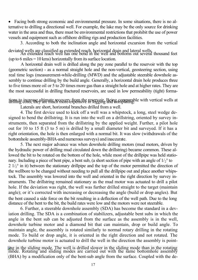
1. Drilling contracts often have a clause stipulating that the well deviates no more
than 3° per 100 ft (30 m) and is contained within a cone with a maximum angle of 5°. This
is a straight hole. The angle in which the well goes out from vertical is called the deviation
and the well is considered to be a crooked hole. In fact, drilling is a three-dimensional process.
A deviation control is the process of keeping the wellbore within some prescribed limitsrelative to the inclination angle, the horizontal excursion from the vertical, or both. Modern ro-
tary rigs can be controlled so that the well is drilled out at a predetermined angle to the
predetermined location. Starting a straight well out at an angle is called kicking off thewell. If it has been cased, a hole, a window, is cut in the casing to kick off the well. The
depth of a well can be measured by two ways: along the length of the wellbore (total depth (TD),
and straight down it (true vertical depth (TVD).
2. Directional, deviation or slant drilling is used for several purposes:
• profitability; drilling offshore is considerably more expensive than drilling on land. An
oil field in very shallow waters can often be more economically developed by deviationdrilling from the beach. The current record holders manage wells over 10 km (6 miles)
away from the surface location at a depth of only 1,600–2,600 m (5,200–8,500 ft). A deep-
water offshore petroleum field is best developed using a large production platform with
numerous (up to about 40) deviated wells that radiate out to the sides. This concept is be-
ing applied to land wells, allowing multiple subsurface locations to be reached from one
pad, reducing environmental impact. It is more economical to drill a crooked hole to test
several potential petroleum reservoirs than to drill several wells to each reservoir. Group-ing more wellheads together on one surface location makes easier and cheaper complete
and produce the wells, ensures less surface area disturbance.• In the emergency situation, when a well is on fire and cannot be approached. A relief well
(reducing an abnormal high pressure) can be drilled at a safe close distance, but without inter-
secting the troubled well. The heavy drilling mud (kill mud) is then pumped from the relief well
through subsurface rocks into the original well to suppress the high pressure and control it.
• If something breaks off or falls down the well and cannot be removed by fishing, the well
can be sidetracked around the obstacle.
• Overcoming a poor drilling location, where vertical access is difficult or not possible.
Natural obstructions such as mountains or severe topographical features frequently prohi- bit building a surface location and drilling a near-vertical well. In a number of cases, fields
are discovered under a town, a lake, and the only way to develop the fields economically is
to drill directionally.
7/27/2019 English for students
http://slidepdf.com/reader/full/english-for-students 17/42
17
• Facing both strong economic and environmental pressure. In some situations, there is no al-
ternative to drilling a directional well. For example, the lake may be the only source for drinking
water in the area and thus, there must be environmental restrictions that prohibit the use of power
vessels and equipment such as offshore drilling rigs and production facilities.
3. According to both the inclination angle and horizontal excursion from the vertical
deviated wells are classified as extended reach, horizontal drain and lateral wells.An extended reach well has one bend in the well and bottoms out several thousand feet
(up to 6 miles = 10 kms) horizontally from its surface location.
A horizontal drain well is drilled along the pay zone parallel to the reservoir with the top
(geometric section) - as a normal straight hole and the non-vertical, geosteering section, using
real time logs (measurement-while-drilling (MWD) and the adjustable steerable downhole as-
sembly to continue drilling by the build angle. Generally, a horizontal drain hole produces three
to five times more oil or 5 to 20 times more gas than a straight hole and at higher rates. They are
the most successful in drilling fractured reservoirs, are used in low permeability (tight) forma-
tions to increase ultimate recovery from the reservoir. Being comparable with vertical wells atdrilling costs, they are much more expensive in logging and completing.
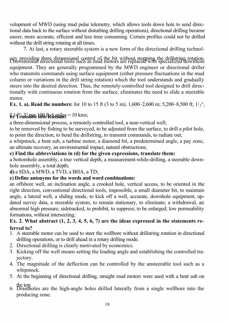
Laterals are short, horizontal branches drilled from a well.4. The first device used to kick off a well was a whipstock, a long, steel wedge de-
signed to bend the drillstring. It is run into the well on a drillstring, oriented by survey in-
struments, then separated from the drillstring by the applied weight. Further, a pilot hole
out for 10 to 15 ft (3 to 5 m) is drilled by a small diameter bit and surveyed. If it has aright orientation, the hole is then enlarged with a normal bit. It was slow (withdrawals of the
bottomhole assembly-BHA-and numerous surveys) and inaccurate.
5. The next major advance was when downhole drilling motors (mud motors, driven by
the hydraulic power of drilling mud circulated down the drillstring) became common. These al-
lowed the bit to be rotated on the bottom of the hole, while most of the drillpipe was held statio-
nary. Including a piece of bent pipe, a bent sub, (a short section of pipe with an angle of 1/2° to
2 1/2° in it) between the stationary drillpipe and the top of the motor permitted the direction of
the wellbore to be changed without needing to pull all the drillpipe out and place another whips-
tock. The assembly was lowered into the well and oriented in the right direction by survey in-
struments. The drillstring remained stationary as the mud motor was actuated to drill a pilot
hole. If the deviation was right, the well was further drilled straight to the target (maintain
angle); or it’s corrected with increasing or decreasing the angle (build or drop angles). But
the bent caused a side force on the bit resulting in a deflection of the well path. Due to the longdistance of the bent to the bit, the build rates were low and the motors were not steerable.
6. Further, a steerable downhole assembly (SDA) has become the standard in a dev-
iation drilling. The SDA is a combination of stabilizers, adjustable bent subs in which the
angle in the bent sub can be adjusted from the surface as the assembly is in the well,
downhole turbine motor and a diamond bit that can maintain, drop or build angle. To
maintain angle, the assembly is rotated similarly to normal rotary drilling in the rotating
mode. To build or drop angle, it is oriented in the right direction and not rotated. The
downhole turbine motor is actuated to drill the well in the direction the assembly is point-
ing in the sliding mode. The well is drilled slower in the sliding mode than in the rotatingmode. Rotating and sliding modes are carried out with the same bottomhole assembly
(BHA) by a modification only of the bent-sub angle from the surface. Coupled with the de-
7/27/2019 English for students
http://slidepdf.com/reader/full/english-for-students 18/42
18
velopment of MWD (using mud pulse telemetry, which allows tools down hole to send direc-
tional data back to the surface without disturbing drilling operations), directional drilling became
easier, more accurate, efficient and less time consuming. Certain profiles could not be drilled
without the drill string rotating at all times.7. At last, a rotary steerable system is a new form of the directional drilling technol-
ogy providing three dimensional control of the bit without stopping the drillstring rotation.Conventional directional tools such as mud motors are replaced with specialized downhole
equipment. They are generally programmed by the MWD engineer or directional drillerwho transmits commands using surface equipment (either pressure fluctuations in the mud
column or variations in the drill string rotation) which the tool understands and gradually
steers into the desired direction. Thus, the remotely-controlled tool designed to drill direc-
tionally with continuous rotation from the surface, eliminates the need to slide a steerable
motor.
Ex. 1. a). Read the numbers: for 10 to 15 ft (3 to 5 m), 1,600–2,600 m; 5,200–8,500 ft; 1/2°,
2 1/2°; 3° per 100 ft, 6 miles = 10 kms;b) Translate into Russian:
a three-dimensional process, a remotely-controlled tool, a near-vertical well;
to be removed by fishing to be surveyed, to be adjusted from the surface, to drill a pilot hole,
to point the direction, to bend the drillstring, to transmit commands, to radiate out;
a whipstock, a bent sub, a turbine motor, a diamond bit, a predetermined angle, a pay zone,
an ultimate recovery, an environmental impact, natural obstructions;
c) Find the abbreviations in (d) for the given expressions, translate them: a bottomhole assembly, a true vertical depth, a measurement-while-drilling, a steerable down-
hole assembly, a total depth;
d) a SDA, a MWD, a TVD, a BHA, a TD;
e) Define antonyms for the words and word combinations: an offshore well, an inclination angle, a crooked hole, vertical access, to be oriented in the
right direction, conventional directional tools, impossible, a small diameter bit, to maintain
angle, a lateral well, a sliding mode, to kick off a well, accurate, downhole equipment, up-
dated survey data, a steerable system, to remain stationary, to eliminate; a withdrawal, an
abnormal high pressure; sidetracked, to prohibit, to suppress; to be enlarged; low permeability
formations, without intersecting;
Ex. 2. What abstract (1, 2, 3, 4, 5, 6, 7) are the ideas expressed in the statements re-
ferred to?1. A steerable motor can be used to steer the wellbore without drillstring rotation in directional
drilling operations, or to drill ahead in a rotary drilling mode.
2. Directional drilling is clearly motivated by economics.
3. Kicking off the well means setting the leading angle and establishing the controlled tra-
jectory.
4. The magnitude of the deflection can be controlled by the unsteerable tool such as a
whipstock.
5. At the beginning of directional drilling, straight mud motors were used with a bent sub on
the top.6. Drainholes are the high-angle holes drilled laterally from a single wellbore into the
producing zone.
7/27/2019 English for students
http://slidepdf.com/reader/full/english-for-students 19/42
19
7. Rotary steerable tools allow three dimensional control of the bit without stopping the drill
string rotation.
8. A wellbore deviated from a straight hole is called a crooked hole.
9. Mud motors with integrated adjustable bent subs are today’s standard offering for general di-rectional drilling applications.
Ex. 3. Comment on figures (from Fig. 2-1 to Fig. 2-6-b):
Fig. 2-1 Fig. 2-2 ( a, b) Fig. 2-3 Fig. 2-4
Fig. 2-5 Fig. 2-6-a Fig. 2-6-b Fig. 2-7Ex. 4. Guess about the equipment and find them in the figures:
1. A device is a short cylinder installed in the drill stem between the lowest drill collar and the
downhole turbodrill to deflect the turbodrill from vertical in order to drill a directional hole.
(_)
2. A tool, placed in the drilling assembly above the bent sub to center the drill collars and stabil-
ize the bit. (_)
3. The least accurate device for deviation drilling. (_)
4. The device is usually a turbine type or positive displacement one. (_)
Ex. 5. 1. Read four abstracts, compare them with the main text to tell us about the abstracts (a, b, c, d, e) having the same information as it in the text (1, 2, 3, 4,
5, 6, 7);
the information, missed in the text but illustrated by the figure (number);
the information, missed in the text and is not illustrated by the figure.
2. Would you choose the same abstract order or change it to present logically a directional
drilling?
a. Sliding is the predominant method to build, control or correct hole angle in mod-
ern directional drilling, which, in fact, is conceptually simple. It’s required to point the bit
in the desired direction by means of the bent sub, which has a small angle offset from the
axis of the drillstring, and a measurement device - to determine the direction of offset. The
bit is rotated with a mud motor (without turning the drillstring).
7/27/2019 English for students
http://slidepdf.com/reader/full/english-for-students 20/42
20
b. With steerable motors, when the desired wellbore direction is attained, the entire
drillstring is rotated and drills straight rather than at an angle. By controlling the amount of
hole drilled in the sliding versus the rotating mode, the wellbore trajectory can be con-
trolled precisely.c. The directional drilling (where the direction of the well changes from time to
time) is usually associated with some enhanced recovery technique (EOR), such as hori-zontal wells being drilled for SAGD (steam assisted gravity drainage).
d. More recently, directional drilling and slant drilling have become common. Slantdrilling allows more than one (usually 4, 6, or 8) wells to be drilled off the same lease site
(pad). Aside from the slant direction, these wells are usually drilled and completed much
like vertical wells.e) In relatively soft sediments, a jet bit can be used to kick off the well. A jet bit is a
tricone bit that has one large and two small nozzles. It is run into the well and then
oriented with a surveying instrument. If the orientation is correct, mud is circulated at
maximum possible flow rate without rotating the drillstring. The hydraulic action of mud jetting out of the large nozzle erodes the well out at that angle. The drillstring is then
pulled and the pilot hole is surveyed. If it is orientated right, the pilot hole is then drilled
out with a normal tricone bit.
Ex. 6. Make up questions to the main text.
Ex. 7. Make the annotation of the text.
3. Grammar exercises.
1. Match the disadvantages of directional drilling and ways to cope with them; transform
the latter to make the sentences with both the Perfect Participle and the absolute participi-
al construction.
The Perfect Participle: having +V3 Having checked the tool they installed it.( it’s used to ex-
press the prior action)
The absolute participial construction: The tool checked (having been checked), they installed it.
Disadvantages (drawbacks) of directional
drilling
Ways to cope with
This is diminished
(overcome) by
The sentences with
participle (the ab-
solute participial
construction)
1. Until the arrival of modern downhole motors
and better tools to measure inclination and azi-
muth of the hole, directional drilling was muchslower than vertical drilling due to the need to
stop regularly and take time consuming surveys,
and due to slower progress in drilling itself
(lower rate of penetration).
a. Providing with
adequately planned
sand control.
2. A difference in operating costs: for wells
with an inclination of less than 40 degrees,
tools to carry out adjustments or repair work
can be lowered by gravity on cable into the
hole. For higher inclinations, more expensiveequipment has to be mobilized to push tools
down the hole.
b. Installing more
efficient downhole
motors and semi-
continuous survey.
7/27/2019 English for students
http://slidepdf.com/reader/full/english-for-students 21/42
21
3. The prevention from coming (influxing) sand
into the well with a high inclination was less re-
liable and needed higher effort. Again, this dis-
advantage has diminished such that, provided
sand control is adequate planned, it is possible
to carry it out reliable.
c. Acquiring suit-
able rotary steera-
ble system.
2. Having read Sperry Drilling Co’s advertisement of mud motors pay atten-
tion to the purpose of advertising (to stress benefit of the goods).
Find Participle I and Participle II in the sentences and transform them as in-
dicated above:
SperryDrill® Mud Motors are designed to operate reliably under a wide
range of downhole conditions.
They reduce drillpipe, collar and casing wear, and minimize related
problems.
The motors can be configured to meet your drilling requirements: stee-rability, build rates, torque, bit speed, flowrates and string rotation.
4. An additional task.
1. Solve the task. The drilling Co has some directional drilling problems. Having looked
through some Internet sites, concerning the manufactures of directional drilling equip-
ment, the chief mechanic of the Co chose that one to improve the matter.
What benefit did he pay attention to? Think and tell us about what is worth taking into
account.
Use phrases:
To my mind he chose _ because having installed the system they solve
In my opinion having equipped the _ with reach/acquire/get
It seems to me that having adjusted improve/enhance
I suppose that having replaced _ with eliminate
Having connected _ to provide
a. DRILLING DIRECTIONALLY from an existing wellbore does not require a
large rotary drilling rig, but rather is done economically using a smaller workover
rig, utilizing downhole motors and a power swivel with small drill pipe. It would be
possible to start a well and have it on production within two weeks. Mobilization and
demobilization between wells is done quickly and inexpensively, and a multi-well
project has the benefit of those economics. We have identified a dozen wells in this
field as candidates for directional drilling
b. Make a Geo-Pilot®, Geo-Pilot® XL Rotary Steerable Systems.
The cornerstone of the services' Pilot ™ Fleet of automated drilling systems, the Geo-
Pilot® rotary steerable system delivers unprecedented speed and up to a 20 percent re-
duction in non-productive time. Using point-the-bit technology, the Geo-Pilot rotary steer-
able system precisely steers the wellbore while rotating the drillstring to reduce drilling
days. The Geo-Pilot service delivers real-time continuous at-bit steering control and for-
mation evaluation to provide an accurate assessment of the wellbore position at all times.
The Geo-Pilot XL rotary steerable system builds on the success of the Geo-Pilot serviceto introduce unprecedented reliability to the industry’s fastest rotary steerable solution.
7/27/2019 English for students
http://slidepdf.com/reader/full/english-for-students 22/42
22
Equipped with a Torsional Efficiency Monitor (TEM™ system), the Geo-Pilot XL system
provides instant warning of the onset of stick-slip (beginning of false work). A new design
allows the Geo-Pilot XL system to overcome a range of harsh drilling conditions. This sys-
tem delivers precise wellbore placement, maximum reservoir exposure (contouring), and
maximum durability (long life).
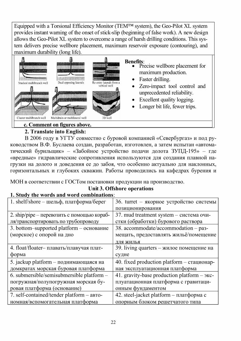
Benefits:• Precise wellbore placement for
maximum production.
• Faster drilling.
• Zero-impact tool control and
unprecedented reliability.
• Excellent quality logging.
• Longer bit life, fewer trips.
c. Comment on figures above.
2. Translate into English:
В 2006 году в УГТУ совместно с буровой компанией «Севербургаз» и под ру-ководством В.Ф. Буслаева создан, разработан, изготовлен, а затем испытан «автома-
тический бурильщик» – «Забойное устройство подачи долота ЗУПД-195» – где
«вредные» гидравлические сопротивления используются для создания плавной на-
грузки на долото и доведения ее до забоя, что особенно актуально для наклонных,горизонтальных и глубоких скважин. Работы проводились на кафедрах бурения и
МОН в соответствии с ГОСТом постановки продукции на производство.
Unit 3. Offshore operations
1. Study the words and word combinations:
1. shelf/shore – шельф, платформа/берег 36. turret – якорное устройство системы
позиционирования
2. ship/pipe – перевозить с помощью кораб-
ля/транспортировать по трубопроводу
37. mud treatment system – система очи-
стки (обработки) бурового раствора
3. bottom–supported platform – основание
(морское) с опорой на дно
38. accommodate/accommodation – раз-
мещать, предоставлять жильё/помещение
для жилья 4. float/floater– плавать/плавучая плат-
форма
39. living quarters – жилое помещение на
судне
5. jackup platform – поднимающаяся на
домкратах морская буровая платформа
40. fixed production platform – стационар-
ная эксплуатационная платформа
6. submersible/semisubmersible platform –
погружная/полупогружная морская бу-
ровая платформа (основание)
41. gravity-base production platform – экс-
плуатационная платформа с гравитаци-
онным фундаментом
7. self-contained/tender platform – авто-
номная/вспомогательная платформа
42. steel-jacket platform – платформа с
опорным блоком решетчатого типа
7/27/2019 English for students
http://slidepdf.com/reader/full/english-for-students 23/42
23
8. production platform – эксплуатационная
платформа
43. spud can – понтон опоры
9. anchor mooring = rack and pinion gear
system – якорная швартовая система
44. caisson – свая-столб большого диа-
метра и глубокого заложения
10. dynamic positioning system (DPS) –
система позиционирования (стабилиза-ции положения)
45. concrete/steel-reinforced concrete – бе-
тон/ железобетон
11. hull/lower hull = mat – опорная плита/
нижний остов
46. рin – соединять болтами
12. open-truss – решетчатой конструкции 47. pile – свая
13. columnar – колоннообразный, под-
держиваемый на столбах
48. guyed-tower – опора башенного типа с
оттяжками
14. main deck – главная палуба 49. sway – раскачиваться
15. cross braced member – опоясывающее
соединение с поперечными раскосами
50. spar platform /deep-draft caisson vessel
(DDCV) – платформа в форме сваи-столба/судно (плавучая платформа) глу-
бокой осадки в форме сваи-столба
16. buoy/buoyant/buoyancy – буй, плаву-
чий, плавучесть
51. compliant platform – управляемая ( ре-
гулируемая) платформа
17. tow – буксировать, буксир 52. detach - отделять, разъединять
18. marine rise = riser – морской стояк,
водоотделяющая колонна
53. with respect to – в отношении, с учё-
том
19. thruster – домкрат, движитель 54. pivot – ось вращения, точка опоры
20. beacon – маяк 55. feasible – возможный, вероятный 21. tension/tensioner – растяжение, на-
тяжное устройство
56. floating production, storage and offload-
ing system (FPSO) – плавучая система
добычи, хранения и отгрузки ( разгрузки)
нефтепродуктов
22. tension-leg platform (TLP) – платфор-
ма с растянутыми опорами
57. current – течение
23. tendon – тросовая тяга 58. inherent – свойственный
24. facilitate – облегчать 59. peculiar – особый, специальный
25. development well – эксплуатационная скважина 60 well template – донная опорная плита
26. subsea wellhead/BOP – подводная
устьевая головка/противовыбросовый
превентор
61. gimbals – универсальный подвес,
универсальное шарнирное соединение
27. ancillary – добавочное оборудование 62. satellite well – скважина-спутник
28. bumper sub – ударный переводник 63. umbilical – шлангокабель
29. tolerate – допускать 64. process – обрабатывать
30. heave/heave compensator – вертикальная
качка/компенсатор вертикальной качки
65. commingle/divert – смешивать/ откло-
нять 31. telescoping joint – раздвижное соеди-
нение
66. boost pressure – рост давления, увели-
чение напора
7/27/2019 English for students
http://slidepdf.com/reader/full/english-for-students 24/42
24
32. ball joint connection – шаровое шар-
нирное соединение
67. tailored – приспособленный, рассчи-
танный
33. moon pool – буровая шахта (в корпусе
судна)
68. tap – открывать
34. payload capacity – допускаемая за-
грузка
69. harsh – сложный, суровый
35. storage/flotation capability – резерву-
арная ёмкость/плавучая способность
70. diver – водолаз
2. Read the text and do exercises:
1. The major difference between onshore and offshore operations is in a top drive
and in the platform upon which the rig is mounted. A top drive is a power swivel located
below the travelling block that drives the drillstring by an electric or hydraulic motor.An offshore platform is a large structure used to house workers and machinery in order to
drill wells in the ocean bed, extract oil and/or natural gas, process the produced fluids and
ship or pipe them to the shore. Most offshore platforms are located on the continentalshelf, though with advances in technology and increasing crude oil prices drilling and pro-
duction in deeper waters becomes possible. A typical platform (a correct name for the
structure in a marine environment) may have around thirty wellheads located on the plat-
form and directional drilling allows reservoirs to be accessed at both different depths and
at remote positions up to 5 miles (8 kilometers) from the platform.
2. There are two main categories of drilling rig structures used offshore: 1) mobile
bottom -supported and floating platforms; 2) production structures used exclusively for
development wells.
The first category of mobile structures includes the following platforms:
• jackup platforms,
• submersible platforms (swamp barges),
• anchor-stationed or dynamically positioned semisubmersible platforms,
• anchor-stationed or dynamically positioned drillships.Production structures used for developing offshore fields from platforms are of two
types: 1) self-contained platforms and 2) tender or jackup assisted platforms. The large
production platform, equipped with a complete set of drilling equipment and some facili-ties for storing and processing, is called self-contained platform. The small floating plat-
form, a tender; anchored next to the platform and having a space to accommodate the liv-ing quarters and many of the rig components, assists the work.
3. Jackup drilling platforms usually have two barge-like hulls and at least three ver-
tical legs through the hulls. They are towed from one drilling location to another with ga-
thered together hulls and elevated legs. On location these platforms anchor themselves by
deploying the legs to the ocean bottom on the lower hull (mat) using a rack and pinion gear sys-
tem on each leg. The upper hull can be jacked up 25 ft (8 m) above the sea using legs. There are
two basic leg configurations of jackup platforms:
• independent-leg type for relatively firm seabed. They are open-truss withcross braced tubular steel members. Each leg has a spud can on the end. The leg penetrates
the sea bottom (doesn’t rest on the mat). Legs are either vertical or tilted slightly outward
to provide stability when the hull is raised out of the water.
7/27/2019 English for students
http://slidepdf.com/reader/full/english-for-students 25/42
25
• Mat-supported type for soft seabed. They are columnar and made of large-
diameter steel tubes. Legs are connected with a mat. The mat rests on the seabed to stably
support the rig. The type is used on flat sea bottom in water depth of up to 50 m. The pene-
tration is slight.
Jackup drilling platforms are used in water depths from 15 to 120 m (about 400 feet)
with a maximum depth of 170 m (550 ft).4. Submersible drilling platforms consist of upper and lower hulls connected by a
network of posts or beams. The drilling equipment and living quarters are installed on theupper hull deck. The lower hull has the buoyancy capacity to float and support the upper
hull and equipment. When water is pumped into the lower hull, the platform submerges
and rests on the seabed to provide a working place for the drilling. Movement and drilling
operations proceed as that of the jackup platform. Most submerged platforms are used only
in shallow waters of about 25 ft ~ 8 to 10 meters. Ship-shaped submersible platforms are
called swamp barges.
5. In water depths greater than 100 m, floaters - drillships and semisubmersible arecommonly used. Drilling operations with floaters require peculiar technologies that are not
used for the operations of mobile bottom-supported drilling platforms. They are station-
keeping and marine riser systems, and drillstring motion compensator.
An adequate stationkeeping system is necessary to keep a floater within acceptable
limits above the subsea wellhead. One of the methods is an anchor mooring system, which
is specifically designed to resist surface forces providing stability during rough weather. It
consists of mooring lines (a combination of chains and wire ropes) and anchors.
The other is a dynamic positioning system (DPS) to maintain position over the well.
The vessel has several thrusters under the bottom. Computers onboard manipulate the
thrusters automatically. Acoustic positioning beacons, located around the subsea wellhead,
send the signals to the vessel; and/or the vessel receives position signals from satellites.
The computers analyze the signals and command movement of the thrusters to keep the
vessel's position within acceptable limits.
The marine riser system provides communication and circulation capability between
the surface and the seafloor and is used at some point during most offshore drilling. It con-
sists of a riser pipe, riser tensioners, and ancillaries. The riser pipe (a string of pipes 17~20
in. in diameter and about 50 ft in length) is connected to the top of subsea BOP and is
pulled up by the riser tensioner system onboard to keep vertical configuration. It serves as
a conduit for returning mud to the surface from the hole, and as a guide for running drillstem and casing from the floater to the hole under the seafloor. The riser can be quickly
detached from the wellhead or blowout preventer stack to facilitate vessel movement dur-
ing adverse weather conditions. A marine riser must be held in tension to prevent the riser
from collapsing under its weight. This can be accomplished by adding buoyant material to
the riser pipe, or by mechanical tensioning devices in water depths greater than 250 ft.
The motion compensator is a device to maintain constant weight on the bit during
drilling operation in spite of oscillation of the floater due to wave motion. One of the de-
vices is a bumper sub. It keeps the bit stable on the bottom-hole. Other device is a heave
compensator. It is placed in the derrick and the top of the drill stem remains stationary, asthe rig heaves up and down because either hydraulic or pneumatic cylinders acting as
springs. The telescoping (slip) joint on the top of the marine riser allows up to 30 ft of ver-

7/27/2019 English for students
http://slidepdf.com/reader/full/english-for-students 26/42
26
tical vessel motion. Lateral motion is tolerated by use of ball joint connections at the seaf-
loor and the surface.
6. Drillships contain all of the equipment and material needed to drill and complete
the well. An opening, called a moon pool, is equipped in the center of the ship from the
main deck to the water. A drilling assembly, a riser pipe, a wellhead equipment, and so
forth are lowered through the moon pool to the sea floor. Some of them have anchoringsystem mounted on a central turret. The ship is rotated about it using thrusters so that the
ship always faces incoming waves. Drillships have the capacity to drill wells in the waters
up to 12,000 feet (3,660 m). However, their use is limited to areas where wave action is not
severe.
These ships have production test facilities and oil storage tanks in addition to the
usual drilling equipment. To improve the efficiency of deepwater operations with the aim
of economic advantages, some drillships have dual-activity drilling system: two sets of
drilling equipment such as mud pumps, drawworks, top drives, and mud treatment sys-
tems. When a hole is drilled by the first drilling system, the second one is used for makingup casing and tubing strings in advance, and so on. Although the dual-activity system in
the deepwater drillship is in the early stage of deployment, it is readily recognized that the
system can save significant time and cost of drilling operations.
7. Semisubmersible drilling platforms (semis) have submerged pontoons (lowerhulls) that are interconnected to the drilling deck by vertical columns. The lower hulls
provide improved stability for the vessel. In drilling operations, the lower hulls are sub-
merged in the water about half-length of the column, but do not rest on the seabed.
A semisubmersible platform can be used in water from 200 to 10,000 feet (60 to 3,050m) deep, and provides a drilling rig generally more stable than does a drillship. Since a
major portion of the vessel is submerged, wave action can be minimized. As on a drillship,
a semisubmersible platform is stabilized by the complex mooring and positioning systems.
But they lack storage capability and payload capacity because of the structure.8. After discovering an offshore field it can be developed using the production (devel-
opment) platform, the structure to house the equipment; production, processing, treating fa-
cilities and an accommodation for the crew.The development platforms can be the following types: fixed production, tension-leg,
compliant (spar) and floating production systems. Modernized semisubmersible platforms and
drillships are also used as production platforms.
Fixed platforms are built on concrete and/or steel legs anchored directly onto the seabed,supporting a deck with space for drilling platforms (rigs), production facilities and crew quarters.
Such platforms due to their immobility are designed for very long term of use. Various types of
structure are employed: such as steel-jacket, concrete caisson and others. Steel jackets are vertic-
al sections made of tubular steel members, and are usually piled into the seabed. Concrete cais-
son or gravity–base platforms (have a large mass of steel-reinforced concrete on the bottom of
the legs, and gravity holds it in position structures) often have in-built oil storage in tanks below
the sea surface. These tanks are often used as a flotation capability, allowing them to be built
close to shore and then floated to their final position where they are sunk to the seabed. Fixed
platforms are economically feasible for installation in water depths up to about 1,700 feet (520m). The bottom-founded platforms providing stable working environment are immobile (in
case of depleting the field) and quite sensitive to water depth (with respect to costs).
7/27/2019 English for students
http://slidepdf.com/reader/full/english-for-students 27/42
27
9. A tension-leg platform (TLP) is a semisubmersible attached to the seabed by ver-
tical members called tendons, which are usually made of hollow steel tubes and tensioned
by excess buoyancy of the platform hull. Tendons are pinned to the seabed directly or indi-
rectly by piles. Motion characteristics of the TLP allow wells to be completed on its deck.It’s a big advantage because wells are one of the most important and expensive compo-
nents of a petroleum production system and ease of access to them is a matter of primeconcern in field development planning. But a TLP has only wellheads and no production
treating facilities onboard. The produced fluids are sent by seabed pipeline to a production plat-form in shallow water for treatment. TLPs are used in water depths up to about 6,000 feet
(2,000 m).
10. A compliant platform is a relatively light production platform that is designed to sway
with wind, waves, and currents. One type, a guyed-tower, is attached to a pivot on the ocean
bottom. Another type, a spar or deep-draft caisson vessel (DDCV) is a floating production
platform in the shape of a closed, vertical cylinder like a buoy. It has a deeply submerged,
spar-shaped hull and a deck structure. Compliant platforms are designed to sustain significantlateral deflections and forces. The guyed-tower types are usually used in water depths ranging
from 1,500 to 3,000 ft (450 to 900 m).
The spar has more inherent stability than a TLP since it has a large counterweight at
the bottom and does not depend on the mooring to hold it upright. It also has the ability, byadjusting the mooring line tensions (using chain-jacks attached to the mooring lines), to
move horizontally and to position itself over wells at some distance from the main plat-
form location. The spar was first applied as storage and loading buoy, further was used for
drilling and production. Like TLP it is possible to put Christmas trees of wells on the plat-form deck, and like FPSO, oil storage capability can be incorporated in the hull, making
this type attractive at isolated deep water locations. The first production spar was anchored
in 1,930 feet (588 m) in the Gulf of Mexico. The world's deepest spar after installing (ex-
pected mid-2009) will be at almost 8,000 feet (2,438 m).
11. The main types of floating production systems are FPSOs (floating production,
storage, and offloading systems). FPSOs consist of large monohull structures, generally
shipshaped, equipped with processing facilities. These platforms are moored to a location
for extended periods, and do not actually drill for oil or gas. Oil produced from offshore
production platforms can be transported to the mainland either by pipeline or by tanker.
When a tanker solution is chosen, it is necessary to accumulate oil in some form of tank
such that an oil tanker is not continuously occupied while sufficient oil is being produced
to fill the tanker. Often the solution is a decommissioned oil tanker which has been
stripped down and equipped with facilities to be connected to a mooring buoy. Oil is ac-
cumulated in the FPSO until there is sufficient amount to fill a transport tanker, at which
point the transport tanker connects to the floating storage unit and offloads the oil. Some
variants of these applications, called FSO (floating storage and offloading system) or FSU
(floating storage unit), are used exclusively for storage purposes, and host very little
process equipment.
12. The offshore field is developed by a directional drilling from one platform.
Wells, often 32 to 40, are drilled through a well template
on the ocean bottom that is used to position and separate the wells. The template is a steel frame with slots for each well. Each
7/27/2019 English for students
http://slidepdf.com/reader/full/english-for-students 28/42
28
slot locates and standardizes the instillation of a well. There are usually one or two extra
slots left undrilled on the template for any further field development.
When a development platform has been set, wells can be drilled with a land-type
well design. Conductor casing is set from above sea level, through the water, to as much as1,500 ft subsea. It provides mud returns and allows the blowout prevention system to exist
in the surface environment. This well design is identical to that onshore as the well control procedures should be employed. The well is completed with a Christmas tree; if it needs
artificial lift gas lift is used. By law offshore wells must be equipped with storm chokes,which are installed on the bottom of the well and are closed either manually or automati-
cally during the emergency.
13. Today more than 1,000 wells worldwide are drilled and completed subsea. Satel-
lite wells (the wells of remote portions of an offshore field or of a small unprofitable by itself
field) are drilled by a mobile offshore drilling unit and completed as subsea wells. They are
then tied to an existing production platform by flowlines and by umbilical connections. These
subsea solutions may consist of single wells or of a manifold centre for multiple wells. Amanifold consists of appropriately arranged valves and piping with associated controls
equipment and a structure to support these components. It allows produced fluid to be
commingled or diverted and injection fluids to be distributed to desired flow paths. With a
subsea manifold, number of flowlines and injection lines between wells and host platform
can be reduced substantially, saving large amount of investment.
14. The advancement of subsea technology has led to development of the equipment
tailored for subsea application. Besides manifolds to collect/divert produced and service
fluids to desired flow paths; it’s important to consider the benefit of multi-phase pumps,
which can boost the pressure of the gas-liquid mixture; gas/liquid separators and asso-
ciated control equipment. For different applications the control equipment can consist of a
surface blowout preventer stack; a subsea blowout preventer stack, a riser-diverter system;
a riser-diverter system with no blowout preventer; a diverter only; or a riserless system.
The presence of choke and kill lines extending from the surface to the stack allow fluids to
be pumped out of the well bypassing the marine riser. They are the source of the procedur-
al differences between onshore and offshore well control operations.
15. Installation and work on a well underwater can be done by three methods: a diver, a
diver in a one-atmosphere diving suit and a remotely operated vehicle. A diver breathing a he-
lium and oxygen mix can work down to 1,000 ft (300 m); in one-atmosphere diving suit - to
2,300 ft (700 m). A remotely operated vehicle (ROV)
is an unmanned submersible that can ef-fectively operate down to 15,000 ft (4600 m). It is connected to a mother ship on the surface
by a cable (umbilical). A closed-circuit television camera on the ROV allows operators on the
surface to manipulate the ROV with thrusters and do work with manipulator arms.
Today the platforms and subsea systems are applied in various combinations, each
aimed at best suiting the particular environment in which they operate. Research and de-
velopment still continue to tap oil and gas in still deeper water and harsher environment.
Ex. 1. Read and translate:
a. Buoy, buoyancy, buoyant; float, floater, floating; tension, tensioner; accommodate, ac-
commodation; treat, treatment; stable, stability; slight, slightly; connect, connection;Semisubmersible, subsea, bypass, interconnected, incorporated, offloading, offshore, on-
shore, reinforced, immobile, undrilled; riserless, jackup;
7/27/2019 English for students
http://slidepdf.com/reader/full/english-for-students 29/42
29
Bottom/mat-supported, self-contained, anchor-stationed, steel-reinforced, tension-leg;
b. a dynamic positioning system (DPS), a tension-leg platform (TLP), a floating production,
storage, and offloading system (FPSO), a remotely operated vehicle (ROV);
Ex. 2. Tell us if the statements are true, false or there is no information in the text:
1. Before the offshore rig is positioned, a subsea site and load-bearing capacity is investi-
gated to make sure it can support the rig.2. Offshore drilling needs floating or bottom-supported rigs/platforms.
3. Offshore platforms can carry on board a number of service systems such as cementing,geophysical logging, and so on.
4. On a drillship a satellite dish is used to track navigational satellites.
5. Jackup platforms are platforms that can be jacked up above the sea using legs that can be lo-
wered much like jacks.
6. Semisubmersible platforms are floating platforms tied to the seabed in a manner that elimi-
nates most vertical movement of the structure.
7. A floating production, storage and offloading vessel (FPSO) is designed to take all of the oilor gas produced from nearby platforms or templates, process it, and store it until the oil or gas
can be offloaded onto a tanker or transported through a pipeline.
8. Tension-leg platforms can be moved from place to place; can be ballasted up or down by al-
tering the amount of flooding in buoyancy tanks.
9. FPSOs are particularly effective in remote or deepwater locations where seabed pipelines are
not cost effective.
Ex. 3. Answer the questions to the text:
1. What is the major difference between onshore and offshore operations?
2. What types of platforms are used for offshore drilling?
3. Are there any differences between jackup and submersible rigs/platforms?
4. Why can floaters -drillships and the semisubmersibles - provide deeper offshore pene-
tration than the bottom-supported platforms?
5. Where is the drillship equipment lowered from?
6. Where is the marine riser connected to?
7. What are vertical and lateral motions tolerated by?
8. Are the production and drilling platforms equipped the same or differently?
9. Why are the fixed platforms deployed in spite of their immobility?
10. What is a tendon?
11. Where can the wells be completed while using TLPs: on the deck of the platform orsubsea?
12. What platform is the best suitable for isolated deep water location? Why?
13. Are FPSOs tailored for drilling?
14. Why is a template worth installing?
15. Is vertical or directional drilling common when a well is taped offshore?
16. What artificial lift method is usually employed for an offshore completion?
17. What is the function of a subsea manifold?
18. Who and what helps work on a well underwater?
19. What is research in offshore operations aimed at?Ex. 4. Comment on figures below.
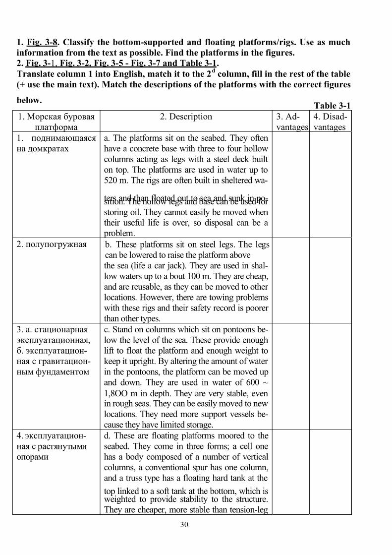
7/27/2019 English for students
http://slidepdf.com/reader/full/english-for-students 30/42
30
1. Fig. 3-8. Classify the bottom-supported and floating platforms/rigs. Use as much
information from the text as possible. Find the platforms in the figures.
2. Fig. 3-1, Fig. 3-2, Fig. 3-5 - Fig. 3-7 and Table 3-1.
Translate column 1 into English, match it to the 2d column, fill in the rest of the table
(+ use the main text). Match the descriptions of the platforms with the correct figures
below.Table 3-1
1. Морская буровая
платформа
2. Description 3. Ad-
vantages
4. Disad-
vantages
1. поднимающаяся
на домкратах
a. The platforms sit on the seabed. They often
have a concrete base with three to four hollow
columns acting as legs with a steel deck built
on top. The platforms are used in water up to
520 m. The rigs are often built in sheltered wa-
ters and then floated out to sea and sunk in po-sition. The hollow legs and base can be used for
storing oil. They cannot easily be moved whentheir useful life is over, so disposal can be a
problem.
2. полупогружная b. These platforms sit on steel legs. The legs
can be lowered to raise the platform above
the sea (life a car jack). They are used in shal-
low waters up to a bout 100 m. They are cheap,
and are reusable, as they can be moved to other
locations. However, there are towing problems
with these rigs and their safety record is poorer
than other types.
3. а. стационарная
эксплуатационная,
б. эксплуатацион-
ная с гравитацион-
ным фундаментом
c. Stand on columns which sit on pontoons be-
low the level of the sea. These provide enough
lift to float the platform and enough weight to
keep it upright. By altering the amount of water
in the pontoons, the platform can be moved up
and down. They are used in water of 600 ~
1,8OO m in depth. They are very stable, evenin rough seas. They can be easily moved to new
locations. They need more support vessels be-
cause they have limited storage.
4. эксплуатацион-
ная с растянутыми
опорами
d. These are floating platforms moored to the
seabed. They come in three forms; a cell one
has a body composed of a number of vertical
columns, a conventional spur has one column,
and a truss type has a floating hard tank at the
top linked to a soft tank at the bottom, which isweighted to provide stability to the structure.
They are cheaper, more stable than tension-leg
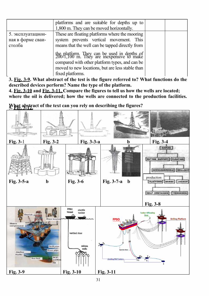
7/27/2019 English for students
http://slidepdf.com/reader/full/english-for-students 31/42
31
platforms and are suitable for depths up to
1,800 m. They can be moved horizontally.
5. эксплуатацион-
ная в форме сваи-
столба
These are floating platforms where the mooring
system prevents vertical movement. This
means that the well can be tapped directly from
the platform. They can be used in depths of200-1,100 m. They are inexpensive to make
compared with other platform types, and can be
moved to new locations, but are less stable than
fixed platforms.
3. Fig. 3-9. What abstract of the test is the figure referred to? What functions do the
described devices perform? Name the type of the platform.
4. Fig. 3-10 and Fig. 3-11. Compare the figures to tell us how the wells are located;
where the oil is delivered; how the wells are connected to the production facilities.
What abstract of the text can you rely on describing the figures?5. Fig. 3-12.
Fig. 3-1 Fig. 3-2 Fig. 3-3-a b Fig. 3-4
Fig. 3-5-a b Fig. 3-6 Fig. 3-7-a b
Fig. 3-8
Fig. 3-9 Fig. 3-10 Fig. 3-11
production
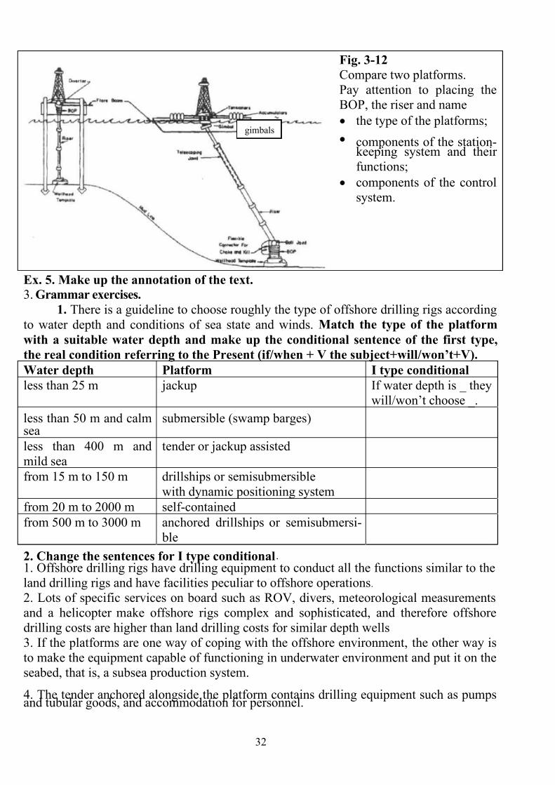
7/27/2019 English for students
http://slidepdf.com/reader/full/english-for-students 32/42
32
gimbals
Fig. 3-12
Compare two platforms.
Pay attention to placing the
BOP, the riser and name
• the type of the platforms;
• components of the station-keeping system and their
functions;
• components of the control
system.
Ex. 5. Make up the annotation of the text.
3. Grammar exercises.
1. There is a guideline to choose roughly the type of offshore drilling rigs according
to water depth and conditions of sea state and winds. Match the type of the platform
with a suitable water depth and make up the conditional sentence of the first type,
the real condition referring to the Present (if/when + V the subject+will/won’t+V).
Water depth Platform I type conditional
less than 25 m jackup If water depth is _ they
will/won’t choose _.
less than 50 m and calmsea
submersible (swamp barges)
less than 400 m and
mild sea
tender or jackup assisted
from 15 m to 150 m drillships or semisubmersible
with dynamic positioning system
from 20 m to 2000 m self-contained
from 500 m to 3000 m anchored drillships or semisubmersi-
ble
2. Change the sentences for I type conditional.1. Offshore drilling rigs have drilling equipment to conduct all the functions similar to the
land drilling rigs and have facilities peculiar to offshore operations.
2. Lots of specific services on board such as ROV, divers, meteorological measurements
and a helicopter make offshore rigs complex and sophisticated, and therefore offshore
drilling costs are higher than land drilling costs for similar depth wells
3. If the platforms are one way of coping with the offshore environment, the other way is
to make the equipment capable of functioning in underwater environment and put it on the
seabed, that is, a subsea production system.
4. The tender anchored alongside the platform contains drilling equipment such as pumpsand tubular goods, and accommodation for personnel.
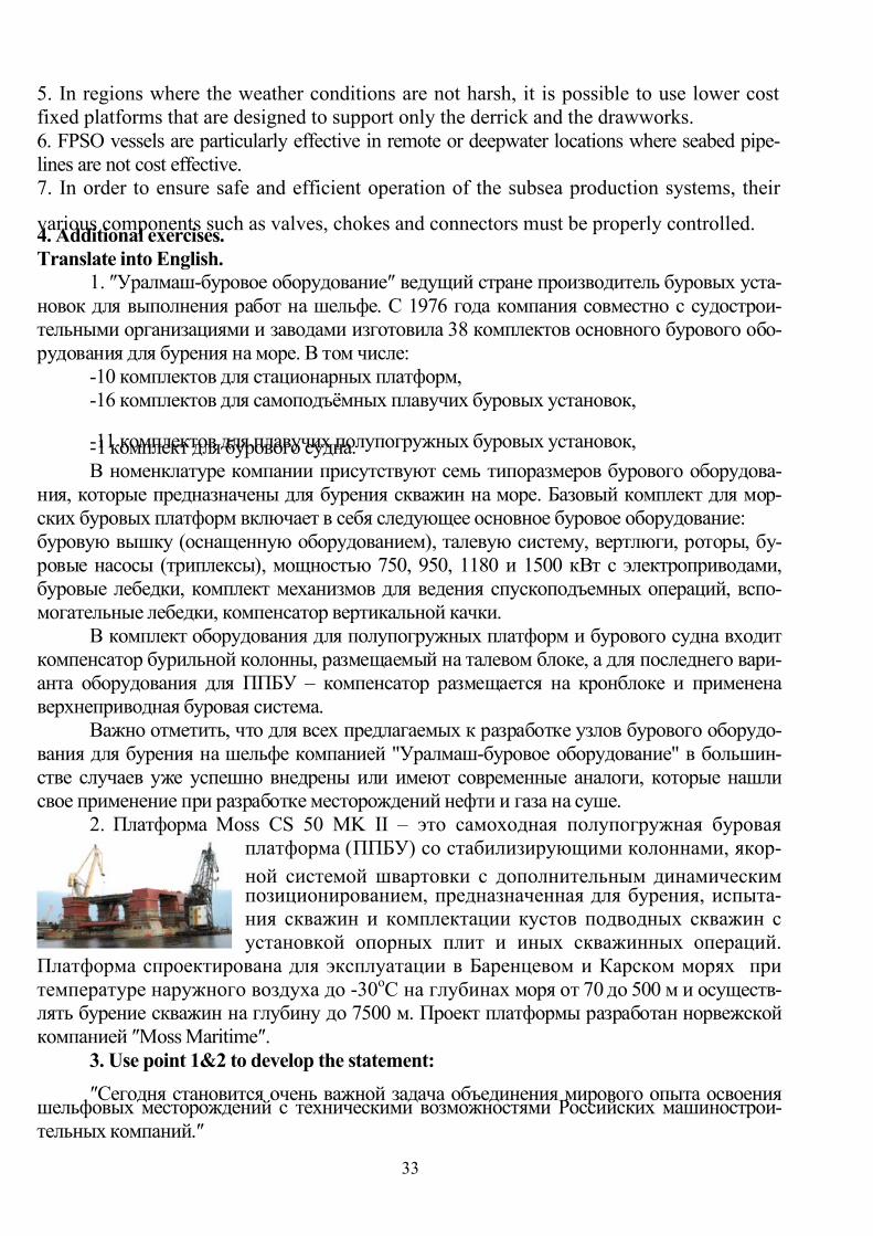
7/27/2019 English for students
http://slidepdf.com/reader/full/english-for-students 33/42
33
5. In regions where the weather conditions are not harsh, it is possible to use lower cost
fixed platforms that are designed to support only the derrick and the drawworks.
6. FPSO vessels are particularly effective in remote or deepwater locations where seabed pipe-
lines are not cost effective.7. In order to ensure safe and efficient operation of the subsea production systems, their
various components such as valves, chokes and connectors must be properly controlled.4. Additional exercises.
Translate into English.
1. ″Уралмаш-буровое оборудование″ ведущий стране производитель буровых уста-
новок для выполнения работ на шельфе. С 1976 года компания совместно с судострои-
тельными организациями и заводами изготовила 38 комплектов основного бурового обо-
рудования для бурения на море.В том числе:
-10 комплектов для стационарных платформ,
-16 комплектов для самоподъёмных плавучих буровых установок,
-11 комплектов для плавучих полупогружных буровых установок,-1 комплект для бурового судна.
В номенклатуре компании присутствуют семь типоразмеров бурового оборудова-
ния, которые предназначены для бурения скважин на море. Базовый комплект для мор-
ских буровых платформ включает в себя следующее основное буровое оборудование:
буровую вышку (оснащенную оборудованием), талевую систему, вертлюги, роторы, бу-
ровые насосы (триплексы), мощностью 750, 950, 1180 и 1500 кВт с электроприводами,
буровые лебедки, комплект механизмов для ведения спускоподъемных операций, вспо-
могательные лебедки, компенсатор вертикальной качки.
В комплект оборудования для полупогружных платформ и бурового судна входит
компенсатор бурильной колонны, размещаемый на талевом блоке, а для последнего вари-
анта оборудования для ППБУ – компенсатор размещается на кронблоке и применена
верхнеприводная буровая система.
Важно отметить, что для всех предлагаемых к разработке узлов бурового оборудо-
вания для бурения на шельфе компанией "Уралмаш-буровое оборудование" в большин-
стве случаев уже успешно внедрены или имеют современные аналоги, которые нашли
свое применение при разработке месторождений нефти и газа на суше.
2. Платформа Moss CS 50 MK II – это самоходная полупогружная буровая
платформа (ППБУ) со стабилизирующими колоннами, якор-
ной системой швартовки с дополнительным динамическим позиционированием, предназначенная для бурения, испыта-
ния скважин и комплектации кустов подводных скважин с
установкой опорных плит и иных скважинных операций.
Платформа спроектирована для эксплуатации в Баренцевом и Карском морях при
температуре наружного воздуха до -30оС на глубинах моря от 70 до 500 м и осуществ-
лять бурение скважин на глубину до 7500 м. Проект платформы разработан норвежской
компанией ″Moss Maritime″.
3. Use point 1&2 to develop the statement:
″Cегодня становится очень важной задача объединения мирового опыта освоения шельфовых месторождений с техническими возможностями Российских машинострои-
тельных компаний.″

7/27/2019 English for students
http://slidepdf.com/reader/full/english-for-students 34/42
34
Unit 4. Problems with wells
1. Study the words and word combinations:
1. workover – ремонт, ремонтные работы 23. sticking/differential sticking – заклини-
вание/прихват бурильной колонны
2. invasive – опущенный (в скважину) 24. dogleg – резкое изменение ствола
скважины
3. snubbing – спуск(инструмента) 25. keyseating – шнопочная канавка
4. retrieve – поднять (инструмент из
скважины)
26. inhibitor – замедлитель, хим. стабили-
затор
5. grapple/grip/grind – захват, заце-
пить/захватить/ размалывать
27. spiral-grooved drill collar – утяжеленная
бурильная труба (УБТ) со спиральными
желобками
6. malfunction – сбой 28. calcium/barium/magnesium sulfate –
сульфат кальция/бария/магния
7. hanger – подвеска 29. scale – окалина 8. packer – сальник, паркер 30. cord – шнур
9. fish/junk – бурильный инструмент/
предмет, упущенный в скважину
31. solvent – растворитель
10. impression block – печать для опреде-
ления положения инструмента, оставше-
гося в скважине
32. bradenhead squeeze – задавливать це-
мент при невысоком давлении через усть-
евую головку с сальниковым устройством
11. spear/overshot – ловильный ёрш, пи-
ка, трубоголовка/овершот
33. squeeze cementing – прокачка/ задавли-
вание под давлением цементного раствора
труб 12. mill/junk mill/milling tools – фреза/
цилиндрическая фреза/дробильные ин-
струменты
34. cement/bridge plug – цемент-
ная/мостовая пробка
13. junk basket – паук для ловли мелких
инструментов в забое
35. mechanical fatigue – механическая ус-
талость
14. washover pipe – промывная труба 36. holiday – просвет, отверстие (в цементе)
15. reamer/tapered mill reamer – расшири-
тель /конусный фрезерный расширитель
37. casing roller – оправка для ремонта об-
садных труб
17. 16. barb – зубец, шип 38. swage – оправка для исправления смя-тия
18. jolt – тряска, трясти, высаживать 39. clog – закупоривать
19. jar – ловильный яс, буровые ножницы 40. abandon – ликвидировать (скважину)
20. surfactant – ПАВ, поверхностно-
активное вещество
41. bond/sonic log – акустическая цементо-
метрия/акустический каротаж
21. lubricant – смазка 42. swabbing – поршневой эффект, поршне-
вание
22. propellant – действующее вещество 43. lead – пломба
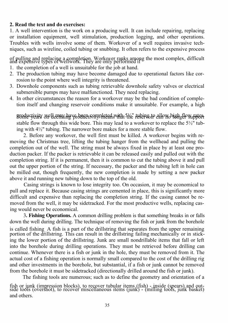
7/27/2019 English for students
http://slidepdf.com/reader/full/english-for-students 35/42
35
2. Read the text and do exercises:
1. A well intervention is the work on a producing well. It can include repairing, replacing
or installation equipment, well stimulation, production logging, and other operations.
Troubles with wells involve some of them. Workover of a well requires invasive tech-niques, such as wireline, coiled tubing or snubbing. It often refers to the expensive process
of pulling and replacing a completion. Workover ranks among the most complex, difficultand expensive types of wellwork. They are only performed if
1. the completion of a well is unsuitable for the job at hand.2. The production tubing may have become damaged due to operational factors like cor-
rosion to the point where well integrity is threatened.
3. Downhole components such as tubing retrievable downhole safety valves or electricalsubmersible pumps may have malfunctioned. They need replacing.
4. In other circumstances the reason for a workover may be the bad condition of comple-
tion itself and changing reservoir conditions make it unsuitable. For example, a high
productivity well may have been completed with 5½" tubing to allow high flow rates.Some years on declining productivity means that the reservoir can no longer support
stable flow through this wide bore. This may lead to a workover to replace the 5½" tub-
ing with 4½" tubing. The narrower bore makes for a more stable flow.
2. Before any workover, the well first must be killed. A workover begins with re-
moving the Christmas tree, lifting the tubing hanger from the wellhead and pulling the
completion out of the well. The string must be always fixed in place by at least one pro-
duction packer. If the packer is retrievable it can be released easily and pulled out with the
completion string. If it is permanent, then it is common to cut the tubing above it and pull
out the upper portion of the string. If necessary, the packer and the tubing left in hole can
be milled out, though frequently, the new completion is made by setting a new packer
above it and running new tubing down to the top of the old.
Casing strings is known to lose integrity too. On occasion, it may be economical to
pull and replace it. Because casing strings are cemented in place, this is significantly more
difficult and expensive than replacing the completion string. If the casing cannot be re-
moved from the well, it may be sidetracked. For the most productive wells, replacing cas-
ing would never be economical.
3. Fishing Operations. A common drilling problem is that something breaks in or falls
down the well during drilling. The technique of removing the fish or junk from the borehole
is called fishing.
A fish is a part of the drillstring that separates from the upper remaining portion of the drillstring. This can result in the drillstring failing mechanically or in stick-
ing the lower portion of the drillstring. Junk are small nondrillable items that fall or left
into the borehole during drilling operations. They must be retrieved before drilling can
continue. Whenever there is a fish or junk in the hole, they must be removed from it. The
actual cost of a fishing operation is normally small compared to the cost of the drilling rig
and other investments in the borehole, but substantial, if a fish or junk cannot be removed
from the borehole it must be sidetracked (directionally drilled around the fish or junk).
The fishing tools are numerous; such as to define the geometry and orientation of a
fish or junk (impression blocks), to recover tubular items (fish) - inside (spears) and out-side tools (overshot), to recover miscellaneous items (junk) - (milling tools, junk basket)
and others.
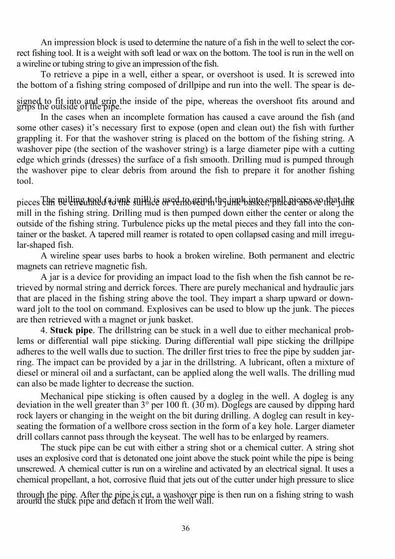
7/27/2019 English for students
http://slidepdf.com/reader/full/english-for-students 36/42
36
An impression block is used to determine the nature of a fish in the well to select the cor-
rect fishing tool. It is a weight with soft lead or wax on the bottom. The tool is run in the well on
a wireline or tubing string to give an impression of the fish.
To retrieve a pipe in a well, either a spear, or overshoot is used. It is screwed intothe bottom of a fishing string composed of drillpipe and run into the well. The spear is de-
signed to fit into and grip the inside of the pipe, whereas the overshoot fits
around andgrips the outside of the pipe.
In the cases when an incomplete formation has caused a cave around the fish (andsome other cases) it’s necessary first to expose (open and clean out) the fish with further
grappling it. For that the washover string is placed on the bottom of the fishing string. A
washover pipe (the section of the washover string) is a large diameter pipe with a cutting
edge which grinds (dresses) the surface of a fish smooth. Drilling mud is pumped through
the washover pipe to clear debris from around the fish to prepare it for another fishing
tool.
The milling tool (a junk mill)
is used to grind the junk into small pieces so that the pieces can be circulated to the surface or removed in a junk basket, placed above the junk
mill in the fishing string. Drilling mud is then pumped down either the center or along the
outside of the fishing string. Turbulence picks up the metal pieces and they fall into the con-
tainer or the basket. A tapered mill reamer is rotated to open collapsed casing and mill irregu-
lar-shaped fish.
A wireline spear uses barbs to hook a broken wireline. Both permanent and electric
magnets can retrieve magnetic fish.
A jar is a device for providing an impact load to the fish when the fish cannot be re-
trieved by normal string and derrick forces. There are purely mechanical and hydraulic jars
that are placed in the fishing string above the tool. They impart a sharp upward or down-
ward jolt to the tool on command. Explosives can be used to blow up the junk. The pieces
are then retrieved with a magnet or junk basket.
4. Stuck pipe. The drillstring can be stuck in a well due to either mechanical prob-
lems or differential wall pipe sticking. During differential wall pipe sticking the drillpipe
adheres to the well walls due to suction. The driller first tries to free the pipe by sudden jar-
ring. The impact can be provided by a jar in the drillstring. A lubricant, often a mixture of
diesel or mineral oil and a surfactant, can be applied along the well walls. The drilling mud
can also be made lighter to decrease the suction.
Mechanical pipe sticking is often caused by a dogleg in the well. A dogleg is anydeviation in the well greater than 3° per 100 ft. (30 m). Doglegs are caused by dipping hard
rock layers or changing in the weight on the bit during drilling. A dogleg can result in key-
seating the formation of a wellbore cross section in the form of a key hole. Larger diameter
drill collars cannot pass through the keyseat. The well has to be enlarged by reamers.
The stuck pipe can be cut with either a string shot or a chemical cutter. A string shot uses an explosive cord that is detonated one joint above the stuck point while the pipe is being
unscrewed. A chemical cutter is run on a wireline and activated by an electrical signal. It uses a
chemical propellant, a hot, corrosive fluid that jets out of the cutter under high pressure to slice
through the pipe. After the pipe is cut, a washover pipe is then run on a fishing string to washaround the stuck pipe and detach it from the well wall.
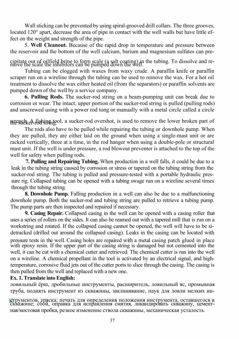
7/27/2019 English for students
http://slidepdf.com/reader/full/english-for-students 37/42
37
Wall sticking can be prevented by using spiral-grooved drill collars. The three grooves,
located 120° apart, decrease the area of pipe in contact with the well walls but have little ef-
fect on the weight and strength of the pipe.
5. Well Cleanout. Because of the rapid drop in temperature and pressure betweenthe reservoir and the bottom of the well calcium, barium and magnesium sulfates can pre-
cipitate out of oilfield brine to form scale (a salt coating) in the tubing. To dissolve and re-move the scale the inhibitors can be pumped down the well.
Tubing can be clogged with waxes from waxy crude. A paraffin knife or paraffinscraper run on a wireline through the tubing can be used to remove the wax. For a hot oil
treatment to dissolve the wax either heated oil (from the separators) or paraffin solvents are
pumped down of the well by a service company.6. Pulling Rods. The sucker-rod string on a beam-pumping unit can break due to
corrosion or wear. The intact, upper portion of the sucker-rod string is pulled (pulling rods)
and unscrewed using with a power rod tong or manually with a metal circle called a circle
wrench. A fishing tool, a sucker-rod overshot, is used to remove the lower broken part ofthe sucker-rod string.
The rods also have to be pulled while repairing the tubing or downhole pump. When
they are pulled, they are either laid on the ground when using a single-mast unit or are
racked vertically, three at a time, in the rod hanger when using a double-pole or structural
mast unit. If the well is under pressure, a rod blowout preventer is attached to the top of the
well for safety when pulling rods.
7. Pulling and Repairing Tubing. When production in a well falls, it could be due to a
leak in the tubing string caused by corrosion or stress or tapered on the tubing string from the
sucker-rod string. The tubing is pulled and pressure-tested with a portable hydraulic pres-
sure rig. Collapsed tubing can be opened with a tubing swage
run on a wireline several times
through the tubing string.
8. Downhole Pump. Falling production in a well can also be due to a malfunctioning
downhole pump. Both the sucker-rod and tubing string are pulled to retrieve a tubing pump.
The pump parts are then inspected and repaired if necessary.
9. Casing Repair. Collapsed casing in the well can be opened with a casing roller that
uses a series of rollers on the sides. It can also be reamed out with a tapered mill that is run on a
workstring and rotated. If the collapsed casing cannot be opened, the well will have to be si-
detracked (drilled out around the collapsed casing). Leaks in the casing can be located with
pressure tests in the well. Casing holes are repaired with a metal casing patch
glued in placewith epoxy resin. If the upper part of the casing string is damaged but not cemented into the
well, it can be cut with a chemical cutter and retrieved. The chemical cutter is run into the well
on a wireline. A chemical propellant in the tool is activated by an electrical signal, and high-
temperature, corrosive fluid jets out of the cutter ports to slice through the casing. The casing is
then pulled from the well and replaced with a new one.
Ex. 1. Translate into English:
ловильный ёрш, дробильные инструменты, расширитель, ловильный яс, промывная
труба, поднять инструмент из скважины, заклинивание, паук для ловли мелких ин-
струментов, тряска; печать для определения положения инструмента, оставшегося в скважине; сбой, оправка для исправления смятия, ликвидировать скважину, цемент-
ная/мостовая пробка, резкое изменение ствола скважины, механическая усталость.
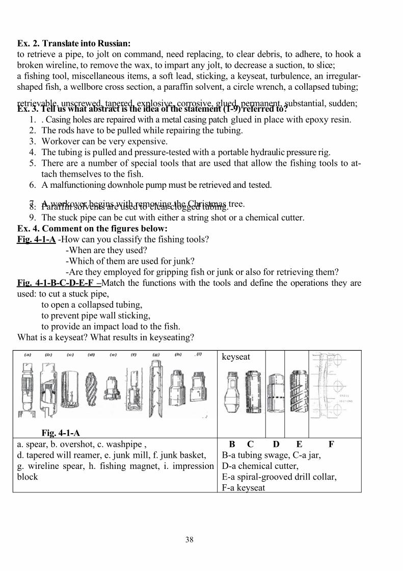
7/27/2019 English for students
http://slidepdf.com/reader/full/english-for-students 38/42
38
Ex. 2. Translate into Russian:
to retrieve a pipe, to jolt on command, need replacing, to clear debris, to adhere, to hook a
broken wireline, to remove the wax, to impart any jolt, to decrease a suction, to slice;
a fishing tool, miscellaneous items, a soft lead, sticking, a keyseat, turbulence, an irregular-shaped fish, a wellbore cross section, a paraffin solvent, a circle wrench, a collapsed tubing;
retrievable, unscrewed, tapered, explosive, corrosive, glued, permanent, substantial, sudden;Ex. 3. Tell us what abstract is the idea of the statement (1-9) referred to?
1. . Casing holes are repaired with a metal casing patch glued in place with epoxy resin.2. The rods have to be pulled while repairing the tubing.
3. Workover can be very expensive.
4. The tubing is pulled and pressure-tested with a portable hydraulic pressure rig.
5. There are a number of special tools that are used that allow the fishing tools to at-
tach themselves to the fish.
6. A malfunctioning downhole pump must be retrieved and tested.
7.
A workover begins with removing the Christmas tree.8. Paraffin solvents are used to clear clogged tubing.
9. The stuck pipe can be cut with either a string shot or a chemical cutter.
Ex. 4. Comment on the figures below:
Fig. 4-1-A -How can you classify the fishing tools?
-When are they used?
-Which of them are used for junk?
-Are they employed for gripping fish or junk or also for retrieving them?
Fig. 4-1-B-C-D-E-F – Match the functions with the tools and define the operations they are
used: to cut a stuck pipe,
to open a collapsed tubing,
to prevent pipe wall sticking,
to provide an impact load to the fish.
What is a keyseat? What results in keyseating?
Fig. 4-1-A
keyseat
a. spear, b. overshot, c. washpipe ,
d. tapered will reamer, e. junk mill, f. junk basket,
g. wireline spear, h. fishing magnet, i. impression
block
B C D E F
B-a tubing swage, C-a jar,
D-a chemical cutter,
E-a spiral-grooved drill collar,
F-a keyseat

7/27/2019 English for students
http://slidepdf.com/reader/full/english-for-students 39/42
39
Ex. 5. Make up the questions to the test according to the numerated abstracts.
Ex. 6. Make up the annotation of the text.
3. Grammar exercises. II and III types of conditional sentences.
II type- the unreal condition referring to the present:
if I +V2 (the Past Simple) – I + would+V(the Simple Infinitive)
III type- the unreal condition referring to the past:if I +had+V3(the Past Perfect) – I+ would+have + V3(the Perfect Infinitive)
If I were a mechanic now I would repair the pump.
If I worked on an offshore platform I’d know a lot about offshore operations.
Read the classification of possible malfunctions which require fishing operations
(causes and the ways of their prevention). Make up at least 5 sentences (one for each
abstract) of II and III types of conditional sentences (5+5).
There are a number of causes for fishing operations. Many of the causes are preventable
by careful planning of the drilling operation and being very watchful for the indication of possible future trouble.
The major causes are
1. Mechanical fatigue and overstress of drillstring components probably accounts for a
large portion of the fish and junk left in a borehole. The most common location of a
drillstring failure is in the drillpipe just above the drill collars, usually in a tool joint at the
base of the threaded pin. Also, drill collar tool joints are failure locations. Again, the base
of the threaded pin is the most likely location. Such possible failures can be prevented by
conducting nondestructive testing on these drillstring components prior to placing them
back in the borehole.2. Stuck drillstring is responsible for many fishing operations. A drillstring can become
stuck because of a number of problems. Pressure differential sticking, caving of the bore-
hole wall, cuttings accumulations and keyseating of drill collars are a few of these prob-
lems. Often when the drillstring becomes stuck it is necessary to unscrew the unstuck por-
tions of the drillstring, remove this portion, and return to the fish with a strengthened, spe-
cialized string for removing the fish. Usually there are signs that the drillstring is in danger
of being stuck prior to the actual sticking of the string. The drilling crew must be constant-
ly alert for these signs and react to them quickly. If these signs are not ignored, fishing op-
erations can be avoided.3. Broken bit components left behind in a borehole when the drillstring is removed and
hand tools and other foreign objects falling in the borehole constitute junk that must be re-
trieved. These components cannot be drilled up during normal drilling operations. They
may be milled with metal drilling bits and other special apparatus that can eventually re-
move these items in pieces. Such junk items can be very difficult to remove.
4. Logging cable and wireline can part due to the logging tool becoming stuck. Such ca-
ble and wireline can be removed by special fishing tools.
5. Production tubulars after long periods of service in a borehole can corrode and become
weakened. When such tubulars are removed during well workovers, these tubulars mayfail mechanically. Programs that have minimized production wells corrosion in production
wells have decreased the necessity for fishing operations in them.
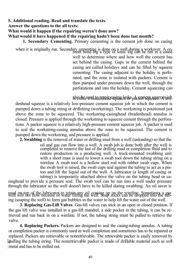
7/27/2019 English for students
http://slidepdf.com/reader/full/english-for-students 40/42
40
5. Additional reading. Read and translate the texts.
Answer the questions to the all texts:
What would it happen if the repairing weren’t done now?
What would it have happened if the repairing hadn’t been done last month?
1. Secondary Cementing. Primary cementing is the cement job done on casing
when it is originally run. Secondary cementing
is done on a well during a workover. A ce-ment bond log a type of sonic log can be run in a cased
well to determine where and how well the cement hasset behind the casing. Gaps in the cement behind the
casing are called holidays and can be filled by squeeze
cementing. The casing adjacent to the holiday is perfo-
rated, and the zone is isolated with packers. Cement is
then pumped under pressure down the well, through the
perforations and into the holiday. Cement squeezing can
also be used to repair casing leaks. A cement squeeze jobis either a bradenhead squeeze or packer squeeze. A bra-
denhead squeeze is a relatively low-pressure cement squeeze job in which the cement is
pumped down a tubing string or drillstring (workstring). The workstring is positioned just
above the zone to be squeezed. The workstring-casinghead (bradenhead) annulus is
closed. Pressure is applied through the workstring to squeeze cement through the perfora-
tions. A packer squeeze is a relatively high-pressure cement squeeze job. A packer is used
to seal the workstring-casing annulus above the zone to be squeezed. The cement is
pumped down the workstring, and pressure is applied.2. Swabbing is the removal of water or drilling mud from a well (unloading) so that the
oil and gas can flow into a well. A swab job is done both after the well iscompleted to remove the last of the drilling mud or completion fluid and torestore production in a producing well. A truck-mounted swabbing unitwith a short mast is used to lower a swab tool down the tubing string on awireline A swab tool is a hollow steel rod with rubber swab cups. Whenthe swab tool is raised, the swab cups seal against the tubing to act as a pis-ton and lift the liquid out of the well. A lubricator (a length of casing ortubing) is temporarily attached above the valve on the tubing head or ca-
singhead to provide a pressure seal. The swab tool can be run into a well under pressurethrough the lubricator so the well doesn't have to be killed during swabbing. An oil saver is
used on top of the lubricator to retain any oil coming up on the wireline. Sometimes a gaswell will not flow because of water filling the well. Soap sticks can be dropped into the tub-ing (soaping the well) to form gas bubbles in the water to help lift the water out of the well.
3. Replacing Gas-Lift Valves. Gas-lift valves can stick in an open or closed position. If
the gas lift valve was installed in a gas-lift mandrel, a side pocket in the tubing, it can be re-
trieved and run back in on a wireline. If not, the tubing string must be pulled to retrieve the
valve.
4. Replacing Packers. Packers are designed to seal the casing-tubing annulus. A tubing
or completion packer is commonly used in well completion and sometimes has to be repaired or
replaced. Packers are retrievable or nonretrievable. The retrievable packer is easily removed by
pulling the tubing string. The nonretrievable packer is made of drillable material such as soft
metal and has to be milled out.

7/27/2019 English for students
http://slidepdf.com/reader/full/english-for-students 41/42
41
5. Recompletion. A well is recomputed by abandoning the original producing zone and
completing in another zone. The well can be either drilled deeper to complete in a deeper zone
or plugged back to complete in a higher zone. The original producing zone must be sealed with
cement in one of three methods. A cement squeeze job can be used to plug perforations in thedepleted zone. Cement can be pumped down a workstring until it fills the well to the desired
level (a cement plug). Also, a bridge plug can be used to mechanically seal that level of the well,and then a dump boiler a long cylinder filled with cement can be run into the well to place the
cement on top of the bridge plug.
My speciality – Machinery and Mechanism of Oil and Gas Industry
Our country is rich in oil and gas. The most important fields are located in West Si-
beria, the Komi Republic, the Caucasus, the Ural- Volga area.
Oil and gas are of great importance as a mineral fuel for engines, communal and
household needs, for industrial enterprises, power stations, for railway and water transport.
That is why oil and gas industry needs highly qualified engineers. To meet the demands of
our Republic in these specialists they are trained at Ukhta State Technical University.We study at the Oil and Gas Production Faculty. This speciality is promising and at-
tracts creative young people. During the course of the study the students attend lectures
and classes learning both core and special subjects included into the curriculum, such as
Exploration the of Oil and Gas Fields, Drilling Equipment, Offshore Structures and others.
We do lab. works in the laboratories equipped with up-to-date instruments and devices.
The knowledge got during the academic year is contributed to the summer practice, where
the undergraduates try to master the know-how concerning oil and gas production.
While studying at the University some gifted students are engaged in research work
under the guidance of the highly-qualified specialists. On the fifth course everybody is busy with carrying out the research which is submitted as the graduation- paper at the end
of the year. After successful passing students are awarded the qualification of a mechanic-
engineer, which gives the young people the opportunity to work at enterprises of oil and
gas industry as well as at scientific-research institutes.
Words and word combinations:
industrial enterprises – промышленные предприятия
to meet the demands – отвечать требованиям
to be engaged in – быть занятым чем-то
to submit a graduation paper – представить дипломную работу to award the qualification – присваивать квалификацию
EXPRESSIONS USED FOR A SUMMARY
The text (article) under consideration entitled (headlined) … is about … .The text (article) I’m going to tell you is (was) taken from the newspaper... .
… was published in… .
The text (article) is devoted to … (is about … ).
The text (article) deals with (dwells on, touches upon ) the subject of … .
The purpose of the author is to inform the reader about (on) …… to provide the reader with new data about (on) …
… to assess the work done by ... (the suggestions that … )
7/27/2019 English for students
http://slidepdf.com/reader/full/english-for-students 42/42
… to stress the importance (necessity) of …
… to disclose the danger of … in case of ignoring …
The text (article) is divided into 2 (3, 4…) parts.
The first part deals with …I’d like to draw your attention to … .
The result is presented … .The data are analysed/compared with … .
The second part is about …The thing I want to mention now is …
Well, on the one hand , but on the other hand … .
There is no denying the fact that … .Judging by this it becomes obvious that … .
Moreover(nevertheless, otherwise , in fact ) … .
The third part touches upon … .
Then comes moment when … .The facts have proved that … .
It turned out that …(to cut the long story short …).
It is said in the conclusion that … .
The author comes to the conclusion that ... .
Personally I found the text (article) interesting (of educational value, thought-provoking,
dull, unconvincing, easy/difficult to understand) because …
The text (article) appeals to me because it provides me with new data (ideas, experience).
… presents new details of (about ) … .
… contributes to my knowledge of … .
… creates a broad panorama of … .
… explores the complexity of …
… offers food for thought.
… helps me to discover the world.
… enriches my outlook.
… makes me reconsider my attitude to … .
I find the text (article) disappointing because it aims at certain effect of … .
… lacks facts (data) of nowadays.
… confirms one’s already held opinions of … .
… idealizes smb. (smb’s idea of …)… reinforces / opposes popular notions of life.
… contradicts to reality.