Embed Size (px)
Citation preview

- 1 -
CONTENTS 1. SPINDLE SIZING ................................ERROR! BOOKMARK NOT DEFINED.
Power / Speed Requirements ............................................................Error! Bookmark not defined. 2. DESIGN DATA SECTION ......................ERROR! BOOKMARK NOT DEFINED.
Cutting Speeds and feeds..................................................................Error! Bookmark not defined. Table 1. Recommended values for precision boring/turning .................................................3 Table 2. Recommended values for precision milling.............................................................3 Table 3. Recommended values for drilling ............................................................................3 Table 4. Recommended values for gun drilling – Carbide Tool............................................4
Estimating Machining Power ...........................................................Error! Bookmark not defined. Table 5. Machining Power calculation:.................................................................................5 Table 6. N- tool rotating speed calculation: ..........................................................................5 Table 7. Feed Factors, C, for Power Constants......................................................................5 Table 8. Tool Wear Factors W...............................................................................................6 Table 9. Power Constants Kp for Ferrous Cast Metals Using Sharp Cutting Tools...............6 Table 10. Power Constant, KP, for High-Temperature Alloys, Tool Steel Stainless ..............6 Steel and Nonferrous Metal, Using Sharp Cutting Tools ......................................................6 Table 11. Power Canstants, Kp for Wrought Steels, Using Sharp Cutting Tools ..................7 Table 12. Formulas for Calculating the Metal Removal Rate, Q...........................................8
DRILLING .......................................................................................Error! Bookmark not defined. Estimating Drilling Thrust, Torque, and Power ...........................Error! Bookmark not defined.
Table 13. Thrust, Torque and Power at Drilling with a Sharp Drill ......................................8 Table 14. Work Material Factor, Kd for Drilling with a Sharp Drill .....................................9 Table 15. Chisel Edge Factors for Torque and Thrust .........................................................10 Table 16. Feed Factors Ff for Drilling..................................................................................10 Table 17. Drill Diameter Factors: FT for Thrust; FM for Torque .........................................11
GRINDING ......................................................................................Error! Bookmark not defined. Grinding Forces, Torque and Power.............................................Error! Bookmark not defined. Grinding Power.............................................................................Error! Bookmark not defined.
Table 18. PG –Grinding Power.............................................................................................11 Table 19. Approximately KC can be taken in next ranges: ..................................................11
ECT – Equivalent chip thickness in Grinding ..........................................................................11 Table 20. ECT = equivalent chip thickness .........................................................................11 Table 21. MRR = metal removal rate ................................................................................12
Basic Rules ...............................................................................Error! Bookmark not defined. Table 22. Grinding parameter recommendations typically range as follows: .....................12
Surface Finish– Ra ....................................................................Error! Bookmark not defined. Side Feed, Roughing and Finishing..........................................Error! Bookmark not defined.
Table 23. C- fraction of grinding wheel width.....................................................................12 Grinding Data Selection ...............................................................Error! Bookmark not defined.
Work materials .........................................................................Error! Bookmark not defined. Table 24. Grindability Groups ............................................................................................13
Maximum wheel speeds ..........................................................Error! Bookmark not defined. Table 25. Max. Peripheral Speeds for Grinding Wheels- Based on ANSI B7.1-1988 ........13 Table 26. Formulas for calculating the rotational speed ......................................................14

- 2 -
3. THE DRIVING MOTOR CHARACTERISTICS......... ERROR! BOOKMARK NOT DEFINED.
Driving Motor Power........................................................................................................................14 Table 27. Driving Motor Power ...........................................................................................14 Table 28. Machine Tool Efficiency Factors E ....................................................................14
Driving Motor Torque ......................................................................................................................14 Table 29. Formulas for calculating of Driving Motor Torque .............................................14
Electrical source parameters .............................................................Error! Bookmark not defined. Table 30. Electrical Formulas ..............................................................................................15 Table 31. Motor Amps at Full Load: ...................................................................................15
IEC Protection Indexes .....................................................................Error! Bookmark not defined. IEC Cooling and Duty Cycle Indexes ..............................................................................................16
4. FLOWCHARTS .................................................................................. 18 FLOWCHART FOR TURNING, BORING AND MILLING.........................................................18 FLOWCHART FOR DRILLING.....................................................................................................19 FLOWCHART FOR GRINDING....................................................................................................20
5. SIZING INSTRUCTIONS ......................ERROR! BOOKMARK NOT DEFINED. General rules for sizing.................................................................Error! Bookmark not defined. "DN" Value...................................................................................Error! Bookmark not defined. Threads Rotation Guide................................................................Error! Bookmark not defined.
6. MOST COMMON SPINDLE NOSE DESIGN ........... ERROR! BOOKMARK NOT DEFINED.
External Taper - G ........................................................................Error! Bookmark not defined. Milling Taper per ANSI B5.18 – M .............................................Error! Bookmark not defined. Milling Taper per ANSI B5.50 – MV ..........................................Error! Bookmark not defined. HSK per DIN 69893 - HA............................................................Error! Bookmark not defined. HSK per DIN 69893 - HB ............................................................Error! Bookmark not defined. HSK per DIN 69893 - HC ............................................................Error! Bookmark not defined. Komet ABS®Connection - K........................................................Error! Bookmark not defined. Other common available spindle nose designs.............................Error! Bookmark not defined.
7. CONVERSION CONSTANTS AND FORMULAS FOR METRIC AND U.S. UNITS.................................................................................................. 24
Table 32. Length Conversion...............................................................................................24 Table 33. Weight Conversion ..............................................................................................24 Table 34. Area Conversion ..................................................................................................24 Table 35. Volume Conversion .............................................................................................24 Table 36. Force and Torque Conversion..............................................................................25 Table 37. Power and Heat Conversion.................................................................................25 Table 38. Pressure Conversion.............................................................................................25 Table 39. Temperature Conversion Table............................................................................26

- 3 -
Table 1. Recommended values for precision boring/turning Hardness Cutting speed - High speed steel Cutting speed - Carbide uncoated Feed rate per revolution
Workpiece material [Bhn] Vc [feet/min] Vc [m/min] Vc [feet/min] Vc [m/min] f [inch] f [mm]
MIN MAX MIN MAX MIN MAX MIN MAX MIN MAX MIN MAX
Cast irons 190...320 16 197 5 60 33 492 10 150 0,003 0,020 0,080 0,500
Steel - plain carbon 85...200 49 394 15 120 197 919 60 280 0,003 0,020 0,080 0,500
Steel - alloys 35...50Rc 16 131 5 40 66 492 20 150 0,003 0,020 0,080 0,500
Steel - tool 50...58Rc 16 66 5 20 49 197 15 60 0,003 0,020 0,080 0,500
Steel - stainless 150...450 16 98 5 30 98 394 30 120 0,003 0,020 0,080 0,500
Aluminum alloys 30. . .150 492 1181 150 360 492 2625 150 800 0,003 0,020 0,080 0,500
Copper alloys 80...100Rb 98 591 30 180 164 1378 50 420 0,003 0,020 0,080 0,500
Nickel alloys 80. ..360 16 131 5 40 16 394 5 120 0,003 0,020 0,080 0,500
Titanium 250...375 16 98 5 30 33 328 10 100 0,003 0,020 0,080 0,500
Table 2. Recommended values for precision milling Hardness Cutting speed - High speed steel Cutting speed - Carbide uncoated Feed rate per tooth
Workpiece material [Bhn] Vc [feet/min] Vc [m/min] Vc [feet/min] Vc [m/min] ft [inch] ft [mm]
MIN MAX MIN MAX MIN MAX MIN MAX MIN MAX MIN MAX
Cast irons 190...320 16 197 5 60 33 492 10 150 0,005 0,012 0,120 0,300
Steel - plain carbon 85...200 49 394 15 120 197 919 60 280 0,005 0,012 0,120 0,300
Steel - alloys 35...50Rc 16 131 5 40 66 492 20 150 0,005 0,012 0,120 0,300
Steel - tool 50...58Rc 16 66 5 20 49 197 15 60 0,005 0,012 0,120 0,300
Steel - stainless 150...450 16 98 5 30 98 394 30 120 0,005 0,012 0,120 0,300
Aluminum alloys 30. . .150 492 1181 150 360 492 2625 150 800 0,005 0,012 0,120 0,300
Copper alloys 80...100Rb 98 591 30 180 164 1378 50 420 0,012 0,012 0,300 0,300
Nickel alloys 80...360 16 131 5 40 16 394 5 120 0,005 0,012 0,120 0,300
Titanium 250...375 16 98 5 30 33 328 10 100 0,005 0,012 0,120 0,300
Table 3. Recommended values for drilling Hardness Cutting speed Feed rate per revolution
Workpiece material [Bhn]
Cutting material Vc [feet/min] Vc [m/min] f [inch] f [mm]
MIN MAX MIN MAX MIN MAX MIN MAX
Cast irons 190...320 High speed steel 33 295 10 90 0,002 0,008 0,050 0,200
Steel - plain carbon 85. . .200 High speed steel 49 148 15 45 0,002 0,008 0,050 0,200
Steel - alloys 35...50Rc High speed steel 16 66 5 20 0,002 0,008 0,050 0,200
Steel - tool 50. . .58Rc High speed steel 16 66 5 20 0,002 0,008 0,050 0,200
Steel - stainless 150...450 High speed steel 16 33 5 10 0,002 0,008 0,050 0,200
Aluminum alloys 30. . . 150 High speed steel 16 377 5 115 0,002 0,008 0,050 0,200
Copper alloys 80...100Rb High speed steel 66 230 20 70 0,002 0,008 0,050 0,200
Nickel alloys 80...360 High speed steel 33 66 10 20 0,002 0,008 0,050 0,200
Titanium 250...375 High speed steel 16 49 5 15 0,002 0,008 0,050 0,200

- 4 -
Table 4. Recommended values for gun drilling – Carbide Tool
Gun Drill Diameters [inch]
Hardness Cutting speed 5/64" - 5/32" 5/32" - 1/4" 1/4" - 1/2" 1/2" - 3/4" 3/4" - 1" 1" - 2" Workpiece material [Bhn] Vc [feet/min] Vc [m/min] Feed - f [inch/revolution]
MIN MAX MIN MAX MIN MAX MIN MAX MIN MAX MIN MAX MIN MAX MIN MAXCast irons- soft 120-220 250 350 76 107 0,0003 0,001
Cast irons - hard 220-320 150 200 46 61 0,00015 0,00025
0,0003 0,00050,0015 0,001 0,003 0,002 0,005 0,003 0,007 0,003
Ductile Iron 140-260 200 300 61 91 0,00015 0,00025 0,0003 0,0005 0,0006 0,001 0,002 0,002
Malleable Iron 110-240 250 350 76 107 0,00015 0,00025 0,0003 0,0005 0,0006 0,001 0,002 0,002
Steel - soft 85...200 425 675 130 206
Steel - Medium 200-325 225 450 69 137
Steel - Hard 325-450 130 200 40 61
0,00015 0,00025 0,0003 0,0005 0,0006 0,001 0,001 0,002
Stainless Steel-Soft 135-275 250 300 76 91
Stainless Steel-Hard 275-425 150 225 46 69 0,00015 0,00025 0,0003 0,0005 0,0006 0,001 0,001 0,002
Aluminum alloys- except Die casting 650 198
Alum.Die casting 650 198
Magnesium 650 198
0,00015 0,00025 0,0003 0,001 0,003 0,005 0,008 0,01
Brass and Bronze 500 600 152 183 0,001 0,003 0,003 0,005 0,005 0,008 0,008 0,01
Copper 350 107 0,00015 0,00025 0,0003 0,0005
0,001 0,003 0,005 0,008
Gun Drill Diameters [inch]
Hardness Cutting speed 2,0 - 4,0 4,0 - 6,5 6,5 - 12,5 12,5 - 19,0 15,0 - 25,0 25,0 - 50,0 Workpiece material
[Bhn] Vc [feet/min] Vc [m/min] Feed - f [mm/revolution]
MIN MAX MIN MAX MIN MAX MIN MAX MIN MAX MIN MAX MIN MAX MIN MAXCast irons- soft 120-220 250 350 76 107 0,008 0,025
Cast irons - hard 220-320 150 200 46 61 0,0038 0,0064 0,008 0,013 0,038 0,025 0,076 0,051 0,127 0,064 0,178 0,076
Ductile Iron 140-260 200 300 61 91 0,0038 0,0064 0,008 0,013 0,015 0,02 0,038 0,051Malleable Iron 110-240 250 350 76 107 0,0038 0,0064 0,008 0,013 0,015 0,02 0,038 0,051
Steel - soft 85...200 425 675 130 206
Steel - Medium 200-325 225 450 69 137
Steel - Hard 325-450 130 200 40 61 0,0038 0,0064 0,008 0,013 0,015 0,02 0,025 0,038Stainless Steel - Soft 135-275 250 300 76 91
Stainless Steel - Hard 275-425 150 225 46 69 0,0038 0,0064 0,008 0,013 0,015 0,02 0,025 0,038Aluminum alloys-
except Die casting 650 198
Alum.Die casting 650 198
Magnesium 650 198 0,0038 0,0064 0,008 0,025 0,076 0,127 0,203 0,254Brass and Bronze 500 600 152 183 0,025 0,076 0,076 0,127 0,127 0,203 0,203 0,254
Copper 350 107 0,0038 0,0064 0,008 0,013 0,025 0,076 0,127 0,203

- 5 -
Table 5. Machining Power calculation:
Pc [HP] = Kp[HP/ in.3/min]×C×Q[in.3/min]×W
Pc [kW] = Kp[kW/ cm3/s]×C×Q[cm3/s]×W
where: Pc = power at the cutting tool; HP, or kW
Kp = power constant, HP/ in.3/min or kW/ cm3/s (Tables 9, 10 and 11)
Q = metal removal rate; in.3/min. or cm3/s (Table 12) C = feed factor for power constant (Table 7) W = tool wear factor (Table 8) V
C = cutting speed, fpm, or m/min (Table 1, 2, 3 and 4)
N = tool rotating speed, rpm or min-1
f = feed rate for turning; in./rev. or mm/rev (Table 1) f = feed rate for planing and shaping; in./stroke, or mm/stroke f
t = feed per tooth; in./tooth, or mm/tooth (Table 2)
fm = feed rate; in./min. or mm/min
dt = maximum depth of cut per tooth: in. or mm
d = depth of cut; in. or mm n
t = number of teeth on milling cutter
D = Tool diameter in inch or mm
Table 6. N- tool rotating speed calculation: Inch Units SI Metric Units
N- Tool rotating speed [rpm] [ ][ ].82.3inDfpmV
N C= [ ][ ]mmD
mVN C min/
47,318=
Table 7. Feed Factors, C, for Power Constants
Inch Unit SI Metric Unit
Feed
in.a C Feed
in.a C Feed
mm.b C Feed
mm.b C
0.001 1.60 0.014 0.97 0.02 1.70 0.35 0.97
0.002 1.40 0.015 0.96 0.05 1.40 0.38 0.95 0.003 1.30 0.016 0.94 0.07 1.30 0.40 0.94 0.004 1.25 0.018 0.92 0.10 1.25 0.45 0.92 0.005 1.19 0.020 0.90 0.12 1.20 0.50 0.90 0.006 1.15 0.022 0.88 0.15 1.15 0.55 0.88 0.007 1.11 0.025 0.86 0.18 1.11 0.60 0.87 0.008 1.08 0.028 0.84 0.20 1.08 0.70 0.84 0.009 1.06 0.030 0.83 0.22 1.06 0.75 0.83 0.010 1.04 0.032 0.82 0.25 1.04 0.80 0.82 0.011 1.02 0.035 0.80 0.28 1.01 0.90 0.80 0.012 1.00 0.040 0.78 0.30 1.00 1.00 0.78 0.013 0.98 0.060 0.72 0.33 0.98 1.50 0.72
- 6 -
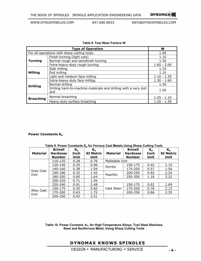
Table 8. Tool Wear Factors W
Power Constants Kp
Table 9. Power Constants Kp for Ferrous Cast Metals Using Sharp Cutting Tools
Material Brinell
Hardness Number
Kp Inch Unit
Kp SI Metric
Unit Material
Brinell Hardness Number
Kp Inch Unit
Kp SI Metric
Unit 110-120 0.28 0.76 Malleable Iron 120-140 0.35 0.96 150-175 0.42 1.15 140-160 0.38 1.04
Ferritic 175-200 0.57 1.56
160-180 0.32 1.42 200-250 0.82 2.24 180-200 0.60 1.64
Pearlitic 250-300 1.18 3.22
200-220 0.71 1.94
Gray Cast Iron
220-240 0.91 2.48 150-175 0.62 1.69 150-175 0.30 0.82 175-200 0.78 2.13 175-200 0.63 1.72
Cast Steel 200-250 0.86 2.35
Alloy Cast Iron
200-250 0.92 2.51
Table 10. Power Constant, KP, for High-Temperature Alloys, Tool Steel Stainless Steel and Nonferrous Metal, Using Sharp Cutting Tools
Type of Operation W For all operations with sharp cutting tools: 1.00
Finish turning (light cuts) 1.10 Normal rough and semifinish turning 1.30 Turning Fxtra-heavy-duty rough turning 1.60 - 2.00 Slab milling 1.10 End milling 1.10 Milling Light and medium face milling 1.10 - 1.25 Extra-heavy-duty face milling 1.30 - 1.60 Normal drilling 1.30 Drilling Drilling hard-to-machine materials and drilling with a very dull drill
1.50
Normal broaching 1.05 - 1.10 Broaching Heavy-duty surface broaching 1.20 - 1.30

- 7 -
Material Brinell Hardness Number
KP Inch Units
KP
Metric Units
Material Brinell Hardness Number
KP Inch Units
KP
Metric Units
High-Temp. Alloys 150-175 0.60 1.64 A 286 165 0.82 2.24 175-200 0.72 1.97 A 286 285 0.93 2.54
Stainless Steel 200-250 0.88 2.40
Chromology 200 0.87 3.22 Zinc Die Cast Alloys
… 0.25 0.68
Chromology 310 1.18 3.00 Pure Copper … 0.91 2.48 Inco 700 330 1.12 3.06 Inco 702 230 1.10 3.00 … 0.83 2.27 Hastelloy-B 230 1.10 3.00 … 0.50 1.36 M-252 230 1.10 3.00 … 0.25 0.68 M-252 310 1.20 3.28
Brass: Hard Medium Soft Leaded … 0.30 0.82
Ti-150 A 340 0.65 1.77 U-500 375 1.10 3.00 … 0.91 2.48 Monel Metal … 1.00 2.73
Bronze: Hard Medium … 0.50 1.36
175-200 0.75 2.05 200-250 0.88 2.40 … 0.25 0.68 250-300 0.98 2.68
Aluminum: Cast Rolled (Hard) … 0.33 0.90
300-350 1.20 3.28 Tool Steel
350-400 1.30 3.55 Magnesium Alloys
… 0.10 0.27
Table 11. Power Canstants, Kp for Wrought Steels, Using Sharp Cutting Tools
Material
Brinell Hardness Number
Kp
Inch Units
Kp SI Metric
Units Plain Carbon Steels
All Plain Carbon Steels
80-100 100-120 120-140 140-160 160-180 180-200 200-220 220-240 240-260 260-280 280-300 300-320 320-340 340-360
0.63 0.66 0.69 0.74 0.78 0.82 0.85 0.89 0.92 0.95 1.00 1.03 1.06 1.14
1.72 1.80 1.88 2.02 2.13 2.24 2.32 2.43 2.51 2.59 2.73 2.81 2.89 3.11
Free Machining Steels AISI 1108, 1109, 1110, 1115, 1116, 1117,1118,1119, 1120, 1125, 1126, 1132
100-120 120-140 140-160 160-180 180-200
0.41 0.42 0.44 0.48 0.50
1.12 1.15 1.20 1.31 1.36
AISI 1137, 1138, 1139, 1140, 1141, 1144, 1145, 1146, 1148, 1151
180-200 200-220 220-240 240-260
0.51 0.55 0.57 0.62
1.39 1.50 1.56 1.69
Alloy Steels AISI 4023, 4024, 4027, 4028, 4032 4037, 4042, 4047, 4137, 4140, 4142 4145, 4147, 4150, 4340, 4640, 4815, 4817, 4820, 5130 5132 5135, 5140 5145, 5150, 6118, 6150, 8637, 8640, 8642, 8645, 8650, 8740
140-160 160-180 180-200 200-220
0.62 0.65 0.69 0.72
1.69 1.77 1.88 1.97

- 8 -
220-240 240-260 260-280 280-300 300-320 320-340 340-360
0.76 0.80 0.84 0.87 0.91 0.96 1.00
2.07 2.18 2.29 2.38 2.48 2.62 2.73
AISI 4130, 4320, 4615, 4620, 4626, 5120, 8615, 8617, 8620, 8622, 8625, 8630, 8720
140-160 160-180 180-200 200-220 220-240 240-260 260-280 280-300 300-320 320-340
0.56 0.59 0.62 0.65 0.70 0.74 0.77 0.80 0.83 0.89
1.53 1.61 1.69 1.77 1.91 2.02 2.10 2.18 2.27 2.43
AISI 1330, I335, 1340, E52100 160-180 180-200 200-220 220-240 240-260 260-280
0.79 0.83 0.87 0.91 0.95 1.00
2.16 2.27 2.38 2.48 2.59 2.73
Table 12. Formulas for Calculating the Metal Removal Rate, Q
Metal Removal Rate
Operation For Inch Units Only Q = in.3/min
For SI Metric Units Only Q = cm3/s
Single-Point Tools (Turning, planing, and Shaping)
12 VC f d V C f d
60
Milling fm w d f m w d 60,000
Surface Broaching 12 VC w nc dt V C w n c d t
60 n
c = number of teeth engaged in work
w = width of cut; in. or mm V
C = cutting speed, fpm, or m/min (see Table 1, 2, 3 and 4)
f = feed rate for turning; in./rev. or mm/rev (see Table 1) f = feed rate for planing and shaping; in./stroke, or mm/stroke f
m = feed rate; in./min. or mm/min
dt = maximum depth of cut per tooth: in. or mm
d = depth of cut; in. or mm
Table 13. Thrust, Torque and Power at Drilling with a Sharp Drill
Inch Units SI Metric Units Thrust T = 2 Kd Ff FT BW+ Kd d2 J W [lb] T= 0.05 Kd Ff FT B W + 0.007 Kd d2 J W [N] Torque M= Kd Ff FM A W [in.-lb] M= 0.000025 Kd Ff FM A W [Nm] Power at Pc = M N / 63.025 [HP] Pc = M N / 9550 [kW]

- 9 -
the cutter where:
Pc = Power at the cutter; hp, or kW
M = Torque; in.- Ib, or Nm T = Thrust; Ib, or N K
d = Work material factor (See Table 14)
Ff = Feed factor (See Table 16)
FT = Thrust factor for drill diameter (See Table 17)
FM = Torque factor for drill diameter (See Table 17)
A = Chisel edge factor for torque (See Table 15) B = Chisel edge factor for thrust (See Table 15) J = Chisel edge factor for thrust (See Table 15) W = Tool wear factor (See Table 8) N = Spindle speed; rpm D = Drill diameter; in, or mm c = Chisel edge length; in, or mm (See Table 15) w = Web thickness at drill point; in, or mm (See Table 15)
Table 14. Work Material Factor, Kd for Drilling with a Sharp Drill
Work Material
Constant Kd
AISI 1117 (Resulfurized free machining mild steel) 12,000 Steel, 200 Bhn 24,000 Steel, 300 Bhn 31,000 Steel, 400 Bhn 34,000 cast Iron, 150 Bhn 14,000 Most Aluminum Alloys 7,000 Most Magnedum Alloys 4,000 Most Brasses 14,000 Leaded Brass 7,000
24,000a for Torque Austenitic Stainless Steel (Type 316)
35,000a for Thrust 18000a for Torque
Titanium Alloy T16A 29,000a for Thrust
Rent 41 40,000ab min. 30,000a for Torque
Hastelloy-c 37,000a for Thrust
aValues based upon a limited number of tests. bWill increase with rapid wear

- 10 -
Table 15. Chisel Edge Factors for Torque and Thrust
c/d Approx.
w/d
Torque Factor
A
Thrust Factor
B
Thrust Factor
J c/d
Approx. w/d
Torque Factor
A
Thrust Factor
B
Thrust Factor
J 0.03 0.025 1.000 1.100 0.001 0.18 0.155 1.085 1.355 0.030 0.05 0.045 1.005 1.140 0.003 0.20 0.175 1.105 1.380 0.040 0.08 0.070 1.015 1.200 0.006 0.25 0.220 1.155 1.445 0.065 0.10 0.085 1.020 1.235 0.010 0.30 0.260 1.235 1.500 0.090 0.13 0.110 1.040 1.270 0.017 0.35 0.300 1.310 1.575 0.120 0.15 0.130 1.080 1.310 0.022 0.40 0.350 1.395 1.620 0.160
Note: For drills of standard design, use c/d = 0.18 For split point drills, use c/d= 0.03 c/d = Length of Chisel Edge / Drill Diameter w/d= Web Thickness at Drill Point / Drill Diameter
Table 16. Feed Factors Ff for Drilling
Inch Units SI Metric Units Feed
inch/rev. Ff Feed
inch/rev. Ff Feed
mm/rev. Ff Feed
mm/rev. Ff
0.0005 0.0023 0.012 0.029 0.01 0.025 0.30 0.382 0.001 0.004 0.013 0.031 0.03 0.060 0.35 0.432 0.002 0.007 0.015 0.035 0.05 0.091 0.40 0.480 0.003 0.010 0.018 0.040 0.08 0.133 0.45 0.528 0.004 0.012 0.020 0.044 0.010 0.158 0.50 0.574 0.005 0.014 0.022 0.047 0.12 0.183 0.55 0.620 0.006 0.017 0.025 0.052 0.15 0.219 0.65 0.708 0.007 0.019 0.030 0.060 0.18 0.254 0.75 0.794 0.008 0.021 0.035 0.068 0.20 0.276 0.90 0.919 0.009 0.023 0.040 0.076 0.22 0.298 1.00 1.000 0.010 0.025 0.050 0.091 0.25 0.330 1.25 1.195

- 11 -
Table 17. Drill Diameter Factors: FT for Thrust; FM for Torque
Inch Units SI Metric Units Drill Dia. inch
FT FM Drill Dia. inch
FT FM Drill Dia. mm
FT FM Drill Dia. mm
FT FM
0.063 0.110 0.007 0.875 0.899 0.786 1.60 1.46 2.33 22.00 11.86 260.8 0.094 0.151 0.014 0.938 0.950 0.891 2.40 2.02 4.84 24.00 12.71 305.1 0.125 0.189 0.024 1.000 1.000 1.000 3.20 2.54 8.12 25.50 13.34 340.2 0.156 0.226 0.035 1.063 1.050 1.116 4.00 3.03 12.12 27.00 13.97 377.1 0.188 0.263 0.049 1.125 1.099 1.236 4.80 3.51 16.84 28.50 14.58 415.6 0.219 0.297 0.065 1.250 1.195 1.494 5.60 3.97 22.22 32.00 16.00 512.0 0.250 0.330 0.082 1.375 1.290 1.774 6.40 4.42 28.26 35.00 17.19 601.4 0.281 0.362 0.102 1.500 1.383 2.075 7.20 4.85 34.93 38.00 18.36 697.6 0.313 0.395 0.124 1.625 1.475 2.396 8.00 5.28 42.22 42.00 19.89 835.3 0.344 0.426 0.146 1.750 1.565 2.738 8.80 5.96 50.13 45.00 21.02 945.8 0.375 0.456 0.171 1.875 1.653 3.100 9.50 6.06 57.53 48.00 22.13 1062 0.438 0.517 0.226 2.000 1.741 3.482 11.00 6.81 74.90 50.00 22.86 1143 0.500 0.574 0.287 2.250 1.913 4.305 12.50 7.54 94.28 58.00 25.75 1493 0.563 0.632 0.355 2.500 2.081 5.203 14.50 8.49 123.1 64.00 27.86 1783 0.625 0.687 0.429 2.750 2.246 6.177 16.00 9.19 147.0 70.00 29.93 2095 0.688 0.741 0.510 3.000 2.408 7.225 17.50 9.87 172.8 76.00 31.96 2429 0.750 0.794 0.596 3.500 2.724 9.535 19.00 10.54 200.3 90.00 36.53 3293 0.813 0.847 0.689 4.000 3.031 12.13 20.00 10.98 219.7 100.00 39.81 3981
P
G = K
C x MRR [HP] or [kW]
Table 18. PG –Grinding Power
Inch Units SI Metric Units
Grinding Power 270,396
MRRKP C
G⋅
= [HP] 000,000,60
MRRKP C
G⋅
= [kW]
where :
PG = Grinding power at the grinding wheel; HP, or kW
KC = specific cutting force [psi] or [N/mm2] – see Table 19.
MRR = metal removal rate [mm3/min] or [in3/min] – see Table 21.
Table 19. Approximately KC can be taken in next ranges: Material KC [N/mm2] KC [psi]
unhardened steel 50,000 to 70,000 N/mm2 7,250,000 to 10,150,000 hardened steel 150,000 to 200,000 N/mm2 21,750,000 to 29,000,000 ECT – Equivalent chip thickness in Grinding
The definition of ECT is: CEL
AECT = [mm] or [inch]
CEL
aafzDECT arz ⋅⋅⋅⋅⋅
=π
ECT = equivalent chip thickness =f(ar,V,V
W,f
S) [mm] or [inch]
( )
Vaelyapproximat
VafV
ECT rrSW ⋅=
+= wV
1
Table 20. ECT = equivalent chip thickness
Inch Units SI Metric Units

- 12 -
ECT
12⋅⋅
=V
fSMRRECT S [inch]
1000⋅⋅
=V
fSMRRECT S [mm]
Table 21. MRR = metal removal rate MRR = SMRR x f
S
MRR = (1000 x ar x V
W) x f
S [mm3/min] or [in3/min]
Inch Units SI Metric Units
MRR
12⋅⋅= VECTMRR [in3/min] 1000⋅⋅= VECTMRR [mm3/min]
Table 22. Grinding parameter recommendations typically range as follows:
Recommended grinding parameter
SI- Metric Units Inch Units
Wheel speed 1200 to 1800 m/min 4000 to 6000 fpm Work speed 20 to 40 m/min 70 to 140 fpm Depth of cut for roughing grinding 0.01 to 0.025 mm 0.0004 to 0.001 inch Depth of cut for finish grinding around 0.005 mm around 0.0002 inch Grit sizes for roughing grinding for easy-to-grind materials
46 to 60
Grit sizes for roughing grinding for difficult-to-grind materials
> 80
Internal griding grit sizes for small holes
100 to 320
Specific metal removal rate – SMRR * 200 to 500 mm3/mm width/min
0.3 to 0.75 in3/inch width/min
Table 23. C- fraction of grinding wheel width Work Material Roughing, C Finishing, C
Steel 2/3 – 3/4 1/3 – 3/8 Stainless Steel 1/2 1/4 Cast Iron 3/4 3/8 Hardened Steel 1/2 1/4

- 13 -
Table 24. Grindability Groups Group Examples
Group 1 Unhardened Steels Group 2 Stainless Steels SAE 30201-30347, 51409-51501 Group 3 Cast iron Group 4 Tool Steels M1, M8, T1, H, O, L, F 52100 Group 5 Tool Steels M2, T2, T5, T6, D2, H41, H42, H43, M50 Group 6 Tool Steels M3, M4, T3, D7 Group 7 Tool Steels T15, M15 Group 8 Heat Resistaut Steels Inconel, Rene etc. Group 9 Carbide Materials P30 Diamond Wheel Group 10 Ceramic Materials
Table 25. Max. Peripheral Speeds for Grinding Wheels- Based on ANSI B7.1-1988 Maximum Operating Surface Speeds
sfpm –feet per minute (m/min)
Depending on Streingth of Bond
Classification No. Types of Wheelsa
Inorganic Bonds Organic Bonds
1
Straight wheels - Type 1, except classsifications 6, 7, 9, 10, 11, and 12 below Type 4b - Taper Side Wheels Types 5, 7, 20, 21, 22, 23, 24, 25, 26 Dish wheels - Type 12 Saucer wheels - Type 13 Cones and plugs - Types 16, 17, 18, 19
5,500 to 6,500 (1674 to 1980)
6,500 to 9,500 (1980 to 2898)
2 Cylinder wheels - Type 2 Segments
5,000 to 6,000 (1524 to 1830)
5,000 to 7,000 (1524 to 2136)
3 Cup shape tool grinding wheels – Types 6 and 11 (for fixed base machines)
4,500 to 6,000 (1374 to 1830)
6,000 to 8,500 (1830 to 2592)
4 Cup shape snagging wheels - Types 6 and 11 (for portable machines)
4,500 to 6,500 (1374 to 1980)
6,000 to 9,500 (1830 to 2898)
5 Abrasive disks 5,500 to 6,500 (1674 to 1980)
5,500 to 8,500 (1674 to 2592)
6 Reinforced wheels - except cutting-off wheels (depending on diameter and thickness) …
9,500 to 16,000 (2898 to 4878)
7 Type 1 wheels for bench and pedestal grinders, Types 1 and 5 also in certain sizes for surface grinders
5,500 to 7,550 (1674 to 2304)
6,500 to 9,500 (1980 to 2898)
8 Diamond and cubic boron nitride wheels Metal bond Steel centered cutting off
to 6,500 (1980) to 12,000 (3660) to 16,000 (4878)
to 9,500 (2898) …
to 16,000 (4878)
9 Cutting-offwheels -- Larger than 16- inch diameter ~ncL reinforced organic)
… 9,500 to 14,200 (2898 to 4326)
10 Cutting-offwheels - l6-inch diameter and smaller (incl. reinforced organic) …
9,500 to 16,000 (2898 to 4878)
11 Thread and flute grinding wheels 8,000 to 12,000 (2436 to 3660)
8,000 to 12,000 (2436 to 3660)
12 Crankshaft and camshaft grinding wheels 5,500 to 8,500 (1674 to 2592)
6,500 to 9,500 (1980 to 2898)

- 14 -
Table 26. Formulas for calculating the rotational speed
Inch Units SI Metric Units
Rotational Speed N [RPM]
π⋅⋅
=D
VN 12
π⋅⋅
=D
VN 1000
Driving Motor Power
The Power at the Driving motor, for all kind of machining is given below:
Table 27. Driving Motor Power Inch Units SI Metric Units
Driving Motor
Power
[ ][ ]HPEHPPPm =
[ ][ ]kWEkWPPm =
where P = power at the cutting tool; HP, or kW P
m = power at the motor; HP, or kW
E = machine tool efficiency factor (see Table 28)
Table 28. Machine Tool Efficiency Factors E Type of Drive E Direct and belt drive 0.90 Back Gear Drive 0.75 Geared Head Drive 0.70 – 0.80 Oil-Hydraulic Drive 0.60 – 0.90
Driving Motor Torque Separate formulas are required for use with customary inch units and for SI metric units:
Table 29. Formulas for calculating of Driving Motor Torque Inch Units SI Metric Units
Motor Torque at 100% Load
[ ][ ]rpmN
HPPT m
m⋅
=025,63
[lb-in] [ ]
[ ]rpmNkWP
T mm
⋅=
9550 [Nm]
where:
Tm - motor torque [lb-in] or [Nm];
Pm - motor power [HP] or [kW];
N - motor rotational speed [rpm]
and some additional units combination:
[ ]
[ ]rpmNHPP
T mm
⋅=
252,5 [lb-feet]
[ ][ ]rpmN
kWPT m
m⋅
=454,84
[lb-in] [ ]
[ ]rpmNHPP
T mm
⋅=
127,7 [Nm]

- 15 -
Table 30. Electrical Formulas Alternating Current
To Find Single Phase Three Phase
To Find Alternating or Direct Current
Amperas when Horsepower is
known pfEVHPI
⋅⋅⋅
=746
pfEV
HPI⋅⋅⋅
⋅=
73.1746
Amperas when Voltage and
Resistance are known
REI = [A]
Amperas when Kilowatts are
known pfVKWI
⋅⋅
=1000
pfV
KWI⋅⋅
⋅=
73.11000
Voltage when
Resistance and Current are known
RIV ⋅= [V]
Amperas when KVA are known V
KVAI 1000⋅=
VKVAI
⋅⋅
=73.1
1000
Resistance when Voltage and
Current are known IER = [Ohm]
Kilowatts 1000
pfVI ⋅⋅
100073.1 pfVI ⋅⋅⋅
KVA 1000
VI ⋅
100073.1 VI ⋅⋅
Horsepower = (Output) 746
pfEVI ⋅⋅⋅
74673.1 pfEVI ⋅⋅⋅⋅
General information (Approximation) at 100% Load: -at 575 V, 3-phase motor draws 1.0 A/HP -at 460 V, 3-phase motor draws 1.25 A/HP -at 230 V, 3-phase motor draws 2.5 A/HP -at 230 V, 1-phase motor draws 5.0 A/HP -at 115 V, 1-phase motor draws 10.0 A/HP
I- Current[A]; V= Voltage[V]; E= Efficiency- see Table 26.; pf= power factor- estimated at 80% for most motors; KVA=Kilovoltsamperes; KW=Kilowatts; R=Resistance[Ohm]; poles of Number
FrequencyRPM ×=
120
Table 31. Motor Amps at Full Load: Alternating Current
[A] Alternating Current [A] HP
Single- Phase
3- phase
DC [A]
HP Single- Phase
3- phase
DC [A]
0.5 4.9 2.0 2.7 25 … 60 92 1 8.0 3.4 4.8 30 … 75 110
1.5 10.0 4.8 6.6 40 … 100 146 2 12.0 6.2 8.5 50 … 120 180 3 17.0 8.6 12.5 60 … 150 215 5 28 14.4 20 75 … 180 268
7.5 40 21.0 29 100 … 240 355 10 50 26.0 38 125 … 300 443 15 … 38.0 56 150 … 360 534 20 … 50.0 74 200 … 480 712
Note: Values given in Table 31. are for all speeds and frequences at 230V. Amperas at voltage other
than 230 Volts can be figured:
NewVoltagefromTableAmpA .230 ⋅
= [A]

- 16 -
Protection Against Solid Objects Protection Against Liquids Number Definition Number Definition
0 No protection 0 No protection
1 Protected against solid
objects of over 50mm (e.g. accidental hand contact)
1
Protected against water vertically dripping
(condensation).
2 Protected against solid objects of over 12mm
(e.g.finger) 2
Protected against water dripping up to 15° from the vertical.
3 Protected against solid objects of over 2.5mm
(e.g. tools, wire) 3
Protected against rain falling at up to 60° from the vertical.
4 Protected against solid objects of over 1mm
(e.g. thin wire) 4
Protected against water splashes from all directions.
5 Protected against dust 5 Protected against jets of water
from all directions.
6 Totally protected against dust 6 Protected against jets of water
comparable to heavy seas.
7
Protected against the effects of immersion to depths of between
0.15 and 1m.
8 Protected against the effects of prolonged immersion at depth.

- 17 -
IEC has additional two digit designations indicating how a motor is cooled:
Designation Cooling design IC 01 Open design IC 40 TENV -Totally Enclosed Non-Ventilated IC 41 TEFC -Totally Enclosed Fan Cooled IC 43 TEAO -Totally Enclosed Air Over
Duty cycles could be designated as continuous, intermittent, or special duty (typically expressed in minutes), IEC uses eight duty cycle designations.
Duty Cycle Designation
Description
S1 Continuous duty. The motor works at a constant load for enough time to reach temperature equilibrium.
S2 Short-time duty. The motor works at a constant load, but not long enough to reach temperature equilibrium, and the rest periods are long enough for the motor to reach ambient temperature.
S3 Intermittent periodic duty. Sequential, identical run and rest cycles with constant load. Temperature equilibrium is never reached. Starting current has little effect on temperature rise.
S4 Intermittent periodic duty with starting. Sequential, identical start, run and rest cycles with constant load. Temperature equilibrium is not reached, but starting current affects temperature rise.
S5 Intermittent periodic duty with electric braking. Sequential, identical cycles of starting, running at constant load, electric braking, and rest. Temperature equilibrium is not reached.
S6 Continuous operation with intermittent load. Sequential, identical cycles of running with constant load and running with no load. No rest periods.
S7 Continuous operation with electric braking. Sequential identical cycles of starting, running at constant load and electric braking. No rest periods.
S8
Continuous operation with periodic changes in load and speed. Sequential, identical duty cycles of start, run at constant load and given speed, then run at other constant loads and speeds. No rest periods.

- 18 -
4. FLOWCHARTS FLOWCHART FOR TURNING, BORING AND MILLING
FLOWCHART FOR TURNING
BORING MILLING
WORKPIECE MATERIAL
AND TOOL TYPE
VC , f – TABLE 1 TABLE 2
KP - TABLE 9,10,11 C - TABLE 7 W - TABLE 8 Q - TABLE 12 E - TABLE 28
MACHINING POWER
P = KP×C×Q×W
TABLE 5 TABLE 6
ROTATION SPEED
π⋅=
DV
N C
TABLE 27
DRIVE MOTOR POWER
EP
PM =
TABLE 29
DRIVE MOTORTORQUE
π⋅⋅
=N
P30T MM
CALCULATED DATA FOR SPINDLE SELECTION:
VARIABLES DEFINED: VC - Cutting Speed f - Feed Rate Kp - Power Constant C - Feed Factor W - Tool Wear Factor Q - Metal Removal Rate D - Tool or Work diameter E - Machine Efficiency Factor N - Rotation Speed P - Machine Power PM - Drive Motor Power TM - Drive Motor Torque

- 19 -
FLOWCHART FOR DRILLING
FLOWCHART FOR DRILLING
WORKPIECE MATERIAL
AND TOOL TYPE
VC , f – TABLE 3 TABLE 4
Kd - TABLE 14 Ff - TABLE 16 FT, FM - TABLE 17 A,B,J - TABLE 15 W - TABLE 8 c/D - TABLE 15 w/D - TABLE 15 E - TABLE 28
MACHINING POWER
30N
MP⋅⋅
=π
TABLE 13
TABLE 29
TABLE 6
ROTATION SPEED
π⋅=
DV
N C
TABLE 27
DRIVE MOTOR POWER
EP
PM =
DRIVE MOTORTORQUE
π⋅⋅
=N
P30T MM
THE SPINDLE BOOK
PART 3. DYNOMAX Spindle catalogue
CALCULATED DATA FOR SPINDLE SELECTION:
1. ROTATION SPEED - N 2. DRIVE MOTOR POWER - PM
3. DRIVE MOTOR TORQUE - TM
VARIABLES DEFINED: VC - Cutting Speed f - Feed Rate Kd - Work material factor Ff - Feed factor FT - Thrust factor FM - Torque factor A - Chisel edge factor for torque B - Chisel edge factor for thrust J - Chisel edge factor for thrust W - Tool Wear Factor c - Chisel edge length w - Web thickness at drill point D - Drill diameter E - Machine Efficiency Factor N - Rotation Speed T - Thrust M - Torque P - Machine Power PM - Drive Motor Power TM - Drive Motor Torque
THRUST
T= Kd×Ff×FT×B×W+ Kd×d2×J×W
TABLE 13
TORQUE
M= Kd×Ff×FM×A×W
TABLE 13
- 20 -
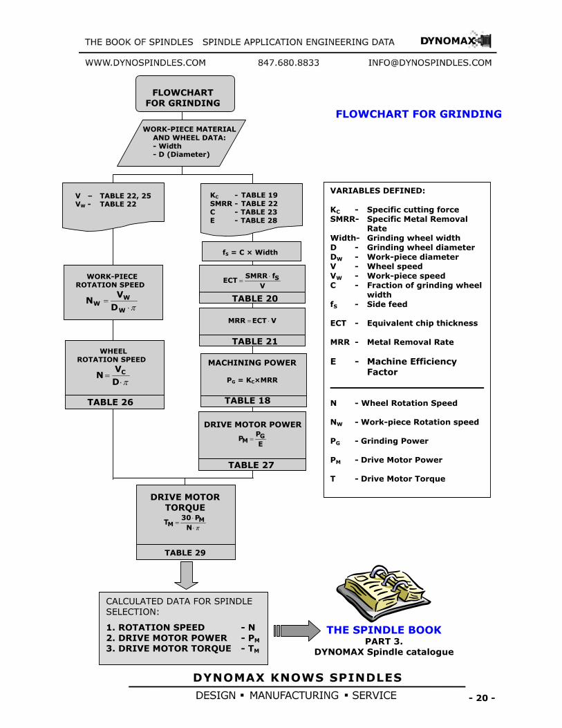
FLOWCHART FOR GRINDING
WORK-PIECE MATERIAL AND WHEEL DATA: - Width - D (Diameter)
V – TABLE 22, 25 VW - TABLE 22
KC - TABLE 19 SMRR - TABLE 22 C - TABLE 23 E - TABLE 28
MACHINING POWER
PG = KC×MRR
TABLE 18
WORK-PIECE ROTATION SPEED
π⋅=
W
WW D
VN
TABLE 29
DRIVE MOTORTORQUE
π⋅⋅
=N
P30T MM
THE SPINDLE BOOK
PART 3. DYNOMAX Spindle catalogue
CALCULATED DATA FOR SPINDLE SELECTION:
1. ROTATION SPEED - N 2. DRIVE MOTOR POWER - PM
3. DRIVE MOTOR TORQUE - TM
VARIABLES DEFINED: KC - Specific cutting force SMRR- Specific Metal Removal Rate Width- Grinding wheel width D - Grinding wheel diameter DW - Work-piece diameter V - Wheel speed VW - Work-piece speed C - Fraction of grinding wheel width fS - Side feed ECT - Equivalent chip thickness MRR - Metal Removal Rate E - Machine Efficiency Factor N - Wheel Rotation Speed NW - Work-piece Rotation speed PG - Grinding Power PM - Drive Motor Power T - Drive Motor Torque
TABLE 26
WHEEL ROTATION SPEED
π⋅=
DV
N C
fS = C × Width
VfSMRR
ECT S⋅=
TABLE 20
VECTMRR ⋅=
TABLE 21
DRIVE MOTOR POWER
EP
P GM =
TABLE 27
FLOWCHART FOR GRINDING

- 21 -
SPINDLE ROTATION COUNTERCLOCKWISE
SPINDLE ROTATION CLOCKWISE
SPINDLE ROTATION EITHER DIRECTION
Size* Bearing** D E F T Thread Key 1.00 30 25.400 47.00 44.00 13.00 .500-13 None 1.25 35 31.750 60.00 57.00 19.00 .500-13 6.35 1.62 45 41.275 74.00 71.00 27.00 .750-16 6.35 2.25 60 57.150 99.00 96.00 39.00 1.125-12 6.35 2.62 70 66.675 114.00 111.00 45.00 1.500-12 9.53
3.00 80 76.200 123.00 120.00 45.00 1.500-12 9.53 3.75 100 95.250 162.00 159.00 64.00 2.250-12 9.53 4.50 120 114.300 194.00 191.00 77.00 2.750-12 9.53 5.00 140 127.000 207.00 204.00 77.00 2.750-12 9.53

- 22 -
Size Bearing* A D E B F C 30 40 31.750 69.832 13.00 14.29 15.88 12.70 40 50 44.450 88.882 16.00 17.50 19.05 12.70 45 70 57.150 101.582 18.00 20.00 25.40 15.88
50 80 69.850 128.569 20.00 27.00 31.75 15.88 60 120 107.950 221.437 38.00 36.00 38.10 19.05
* Minimum front bearing bore size [mm]
Size Bearing* A D E 30 40 31.750 50.00 13.00 40 50 44.450 65.00 16.00 45 70 57.150 85.00 18.00 50 80 69.850 100.00 20.00
60 120 107.950 160.00 38.00
* Minimum front bearing bore size [mm]
Size Bearing* A D F E HSK 25A 30 19.000 25.00 9.40 10.00 HSK 32A 40 24.000 32.00 11.40 12.00 HSK 40A 50 30.000 40.00 14.40 15.00 HSK 50A 60 38.000 50.00 17.90 18.00 HSK 63A 70 48.000 63.00 22.40 23.00
HSK 80A 90 60.000 80.00 28.40 29.00 HSK 100A 110 75.000 100.00 35.40 36.00 HSK 125A 130 95.000 125.00 44.40 45.00 HSK 160A 170 120.000 160.00 57.40 58.00

- 23 -
* Minimum front bearing bore size [mm]
Size Bearing* A D F E
HSK 40B 50 24.000 40.00 20.50 21.00 HSK 50B 60 30.000 50.00 25.50 26.00 HSK 63B 70 38.000 63.00 25.50 26.00 HSK 80B 90 48.000 80.00 33.00 34.00 HSK 100B 110 60.000 100.00 41.00 42.00 HSK 125B 130 75.000 125.00 51.00 52.00 HSK 160B 170 95.000 160.00 64.00 65.00
* Minimum front bearing bore size [mm]
Clamp Force (kN)
Size Bearing* A D F E Guhring Mapal HSK 32C 40 24.000 32.00 11.40 12.00 9 11 HSK 40C 50 30.000 40.00 14.40 15.00 15 15 HSK 50C 60 38.000 50.00 17.90 18.00 23 21 HSK 63C 70 48.000 63.00 22.40 23.00 33 30 HSK 80C 90 60.000 80.00 28.40 29.00 50 38 HSK 100C 110 75.000 100.00 35.40 36.00 70 50
* Minimum front bearing bore size [mm]
Size Bearing* A D F E ABS 25 30 13.000 25.000 24.00 20.00 ABS 32 35 16.000 32.000 27.00 23.00 ABS 40 40 20.000 40.000 31.00 27.00 ABS 50 50 28.000 50.000 36.00 32.00 ABS 63 60 34.000 63.000 43.00 39.00
ABS 80 80 46.000 80.000 48.00 44.00 ABS 100 100 56.000 100.000 60.00 52.00 ABS 125 130 70.000 125.000 76.00 64.00 ABS 160 160 90.000 160.000 96.00 80.00 ABS 200 200 112.000 200.000 116.00 100.00
* Minimum front bearing bore size [mm]

- 24 -
7. Conversion Constants and Formulas for Metric and U.S. Units
Table 32. Length Conversion
[µm] micrometer × 0.00003937 = inches [in] [in] Inches × 25,400.1 = micrometer [µm] [mm] Milimeters × 0.039370 = inches. [in] [in] Inches × 25.4001 = milimeters. [mm] [m] Meters × 39.370 = inches. [in] [in] Inches × .0254 = meters. [m] [m] Meters × 3.2808 = feet. [ft] [ft] Feet × .30480 = meters. [m] [m] Meters × 1.09361 = yards. [yd] [yd] Yard × .91440 = meters. [m] [km] Kilometers × 3,280.8 = feet. [ft] [ft] Feet × .0003048 = kilometers [km]. [km] Kilometers × .62137 = Statute Miles. Statute Miles × 1.60935 = kilometers. [km] [km] Kilometers × .53959 = Nautical Miles. Nautical Miles × 1.85325 = kilometers. [km]
Table 33. Weight Conversion
[g] Grams × 981 = dynes. Dynes × .0010193 = grams. [g] [g] Grams × 15.432 = grains Grains × .0648 = grams. [g] [g] Grams × .03527 = ounces (Avd.). [oz] [oz] Ounces (Avd.) × 28.35 = grams. [g] [g]Grams × .033818 = fluid ounces (water). [oz] [oz] Fluid Ounces (water) × 29.57 = grams. [g] [kg] Kilograms × 35.27 = ounces (Avd.). [oz] [ozg Ounces (Avd.) × .02835 = kilograms. [kg] [fg] Kilograms × 2.20462 = pounds (Avd.). [lb] [lb] Pounds (Avd.) × .45359 = kilograms. [kg] Metric Tons (1000 kg.) × 1.10231 = Net Ton (2000 lb). Net Ton (2000 lb) × .90719 = Metric Tons (1000 kg). Metric Tons (1000 kg.) × .98421 = Gross Ton (2242 lb). Gross Ton (2240 lb) × 1.01605 = Metric Ton (1000 kg)
Table 34. Area Conversion
[mm2] Square Milimeters × .00155 = sqare inches. [in2] [in2] Square Inches × 645.136 = square milimeters. [mm2] [cm2]Square Centimeters × .155 = square inches. [in2] [in2] Square Inches × 6.45163 = square centimeters. [cm2 [m2] Square Meters × 10.76387 = square feet. [ft2] [ft2] Square Feet × .0929 = square meters. [m2] [m2] Square Meters × 1.19599 = square yards. [yd2] [yd2] Square Yards × .83613 = square meters. [m2] [ha] Hectares × 2.47104 = acres. Acres × .40469 = hectares. [ha] [km2] Square Kilometers × 247.104 = acres. Acres × .0040469 = square kilometers. [km2] [km2] Square Kilometers × .3861 = square miles. Square Miles × 2.5899 = square kilometers [km2]
Table 35. Volume Conversion [cm3] Cubic centimeters × .033818 = fluid ounces. Fluid Ounces × 29.57 = cubic centimeters. [cm3] [cm3] Cubic centimeters × .061023 = cubic inches. [in3] [in3]Cubic Inches × 16.387 = cubic centimeters. [cm3] [cm3] Cubic centimeters × .271 = fluid drams. Fluid Drams × 3.69 = cubic centimeters. [cm3] [l] Liters × 61.023 = cubic inches. [in3] [in3]Cubic Inches × .016387 = liters. [l] [l] Liters × 1.05668 = quarts. Quarts × .94636 = liters. [l] [l] Liters × .26417 = gallons. Gallons × 3.78543 = liters. [l] [l] Liters × .035317 = cubic feet. [ft3] [ft3] Cubic Feet × 28.316 = liters. [l] [hl] Hectoliters × 26.417 = gallons. Gallons × .0378543 = hectoliters. [hl] [hl] Hectoliters × 3. 5317 = cubic feet. [ft3] [ft3] Cubic Feet × .28316 = hectoliters. [hl] [hl] Hectoliters × 2.83794 = bushel (2150.42 cu. in.). Bushels (2150.42 cu. in.) × .352379 = hectoliters. [hl] [hl] Hectoliters ×.1308 = cubic yards. [yd3] [yd3]Cubic Yards × 7.645 = hectoliters. [hl] [m3] Cubic Meters × 264.17 = gallons. Gallons × .00378543 = cubic meters. [m3] [m3] Cubic Meters × 35.317 = cubic feet. [ft3] [ft3] Cubic Feet × .028316 = cubic meters. [m3] [m3] Cubic Meters × .1308 = cubic yards. [yd3] [yd3]Cubic Yards × 7.645 = cubic meters. [m3] [m3] Cubic Meters × 61,023.76 = cubic inches. [in3] [in3] Cubic Inches × 0.000016387 = cubic meters. [m3]

- 25 -
Table 36. Force and Torque Conversion [lb] pounds × 4.448 = Newton [N] [N] Newton × 0.2248 = pounds [lb] [lb-in] pound-inches × 0.11298 = Newton-meter [Nm] [Nm] Newton-meters × 8.851 = pound-inches [lb-in] [lb-ft] pound-feet × 1.356 = Newton-meter [Nm] [Nm] Newton-meters × 0.7376 = pound-feet [lb-ft] [oz-in] ounce-inches × 0.007062 = Newton-meter[Nm] [Nm] Newton-meters × 141.60 = ounce-inches [oz-in] [oz-in] ounce-inches × 0.005208 = pound-feet [lb-ft] [lb-ft] pound-feet × 192 = ounce-inches [oz-in] [oz-in] ounce-inches × 0.0625 = pound-inches [lb-in] [lb-in] pound-inches × 16 = ounce-inches [oz-in]
Table 37. Power and Heat Conversion [kW] Kilowatts × 1.341 = Horsepower. [HP] Horsepower × 0.746 = kilowatts. [kW] [kWh]Kilowatt Hours × 3415 = B.T.U. B.T.U. × 0.00029282 = kilowatt hours. [kWh] [Nm[ Newton-meters × 8.851 = pound-inches. [lb-in] Pound-Inches × 0.11298 = Newton-meters. [Nm] [cal] Calorie × 0.003968 = B.T.U. B.T.U. × 252 = calories. [cal] [J]Joules × 0.7373 = pound-feet. [lb-ft] Pound-Feet × 1.3563 = joules. [J] Cheval Vapeur × 0.9863 = Horsepower. [HP] Horsepower × 1.014 = Cheval Vapeur.
Table 38. Pressure Conversion
[Pa] Pascal × 1 = Newton per square meter [N/m2] [N/m2] × 1 = [Pa] [Pa] Pascal × 0.0001450=pounds per square inch [psi] [psi] pounds per square inch × 6894.8= Pascal [Pa] [Pa] Pascal × 0.02089= pounds per square foot [lb/ft2] [lb/ft2] pounds per square foot × 47.8698= Pascal [Pa] [atm] Atmosphere × 1 = [bar] [bar] × 1 = Atmosphere [atm] [atm] Atmosphere × 14.50 = [psi] [psi]pound per square inch×0.0680 = Atmosp.[atm] [atm] Atmosphere × 2116.8 = [lb/ft2] [lb/ft2]pound per square foot×0.000472= Atmosp.[atm] [atm] Atmosphere × 101325 = [Pa] or [N/m2] [Pa] Pascal × 0.000009869 = Atmosp.[atm] [N/mm2] × 145 = pounds per square inch [psi] [psi]pound per square inch × 0.006897 = [N/mm2]

- 26 -
Table 39. Temperature Conversion Table
100C
18032F °
=−°
Locate known temperature in °C/°F column. Read converted temperature in °F or °C column.
°F = (9/5 x °C) + 32 °C
°C= 5/9 (°F -32)
°C °C/°F °F °C °C/°F °F °C °C/°F °F
-45.4 -50 -58 15.5 60 140 76.5 170 338
-42.7 -45 -49 18.3 65 149 79.3 175 347
-40 -40 -40 21.1 70 158 82.1 180 356
-37.2 -35 -31 23.9 75 167 85 185 365
-34.4 -30 -22 26.6 80 176 87.6 190 374
-32.2 -25 -13 29.4 85 185 90.4 195 383
-29.4 -20 -4 32.2 90 194 93.2 200 392
-26.6 -15 5 35 95 203 96 205 401
-23.8 -10 14 37.8 100 212 98.8 210 410
-20.5 -5 23 40.5 105 221 101.6 215 419
-17.8 0 32 43.4 110 230 104.4 220 428
-15 5 41 46.1 115 239 107.2 225 437
-12.2 10 50 48.9 120 248 110 230 446
-9.4 15 59 51.6 125 257 112.8 235 455
-6. 7 20 68 54.4 130 266 115.6 240 464
-3.9 25 77 57.1 135 275 118.2 245 473
-1.1 30 86 60 140 284 120.9 250 482
1.7 35 95 62.7 145 293 123.7 255 491
4.4 40 104 65.5 150 302 126.5 260 500
7.2 45 113 68.3 155 311 129.3 265 509
10 50 122 71 160 320 132.2 270 518
12.8 55 131 73.8 165 329 136 275 527