Embed Size (px)
Citation preview

Learning ObjectivesOn completion of this unit a learner will be able to
• Describe ferrous metals , non-ferrous metals and non-metals
• Know the properties and uses of ferrous and non ferrous metals
• Know the safety precautions to be followed in a work shop
1.0 IntroductionEngineering materials are those which are extensively used in various
engineering applications such as used for construction of bridges, machine tools,automobiles, locomotives, ships, space crafts and many more.Steel is extensivelyused in construction of bridges.Iron is used for various machine tools.Aircraftshave aluminium bodies.Large number of household ,industrial goods,electronicsgoods are made using plastics like TV cabinets computer bodies & toys.
Classification of Engineering Materials
Engineering materials are basically classified into two groups namely metalsand non-metals, and their sub classification is given below.
Engineering Materials
1UNIT

Automobile Engineering Technician2
Classification of Engineering Materials
Mechanical Properties of Metals
The mechanical properties that determine the behavior of metals underapplied forces. These properties are most important for the designing point ofview.
1. Strength : Ability of a material to resist loads without failure.
2. Tensile Strength : Ability of a material in tension to withstand stresswithout failure.
3. Shear Strength : Ability of a material to withstand transverse loadswithout fracture.
4. Elasticity : Property of material which enables it to regain its originalshape after deformation with in the elastic limit.
5. Stiffness : Property of material which enables it to resist deformation.
6. Plasticity : Ability of material to be deformed permanently withoutfracture even after removal of force.
Engineering Materials
Metals Non Metals
Ferrousmetals
Non Ferrousmetals Polymers Ceramics
Wrought iron,Carbon Steels,Alloy steels,Cast Iron.
Al, Cu,Sl, tin,zn
Thermostatic plastics
Thermoplastic
Phenolformal
dehyde Refractoreis,Abrasives,glass, Cementand concrete
PVCPolythene,Acrylic resins

Paper - I Workshop Technology 3
7. Ductility : Ability of a material to deform plastically without ruptureunder tensile load.
8. Malleability : Property which enables the metal to withstanddeformation by a compressive load without fracture.
9. Brittleness : Property of the material of sudden fracture without anyappreciable deformation.
10. Hardness : Property of the material which enables it to resist abrasion,indentation, machining and scratching.
11. Toughness : Ability of material to absorb maximum energy upto fracturetakes place.
12. Fatigue : Failure of material under repeated (cyclic) loads or fluctuatingloads.
13. Weldability : Ability of a material to be joined by welding
14. Castability : Property of a metal which indicates the ease with whichit can be cast into different shapes and sizes from its liquid state.
Ferrous Metals
The metals which contain iron as base are called ferrous metals. Eg. Castiron, Alloy steels etc. These are clssified as
1) Pig iron 2) Cast iron 3) Wrought iron
4) Carbon Steel 5) Alloy steel.
The properties and uses of common engineering materials.
1.1 Cast IronPig iron remelted and there by refined together with definite amount of lime
stone,steel scrap and spoiled castings in cupola. It contain 2-4% carbon, asmall percentage of silicon, sulphur, phosphorus and manganese.
Properties of Cast Iron
1. It has good fluidity
2. It can be easily machined
3. It is brittle in nature
4. It is resistance to deformation

Automobile Engineering Technician4
5. It is wear resistant.
Uses of Cast Iron
1. It is used in making pipes
2. It is used for making machine bodies
3. It is used in making automotive industry parts.
1.2 Mild SteelThese are also called low carbon steels having carbon content of 0.15 -
0.3%.
Properties of Mild Steel
1. It has low fluidity.
2. It has good tensile strength.
3. It is ductile
4. It can be cold worked easily.
Uses
1. It is used for making structures
2. It is used for making nuts and bolts
3. It is used for making machine components.
4. It is used for making boiler plates.
1.3 High Carbon SteelsHigh carbon steels have more than 0.60% carbon i.e. 0.6 - 0.9% carbon .
It is generally used for making parts requiring strength, hardness and wearresistance.
Properties of High Carbon Steels
(1) It has good strength
(2) It has high toughness
(3) It has increased wear resistance.

Paper - I Workshop Technology 5
Uses
1. It is used for making Drop hammers
2. It is used for making Screw drivers
3. It is used for making laminated Springs
4. It is used for making gears.
5. It is used for making piston rings
1.4 Alloy SteelsSteel is a metal alloy consisting mostly of iron, in addition to small amount
of carbon, depending upon the grade and quality of the steel. Alloy steel is anytype of steel to which one or more elements besides carbon have been added toproduce a desired physical properties. The most common alloying elementsadded to steel are Chromium, Nickel, manganese, silicon, Vanadium etc. .
Properties of Alloy Steel
(1) High Strength
(2) High corrosion resistance
(3) High wear resistance
(4) Good toughness.
Uses
(1) It is used for making Aeroplane parts
(2) It is used for making automobile parts
(3) It is used for railway track work
(4) It is used for making locomotive parts
1.5 Stainless SteelIt contains 18% chromium, 8% nickle, 0.06% to 0.12% carbon. They are
called stainless because in the presence of oxygen, they develop a thin adherentfilm of chromium oxide that protects the metal from corrosion.
Properties of Stainless Steel
1. It has high corrosion resistance.

Automobile Engineering Technician6
2. It has high strength
3. Good toughness
4. It posses non magnetic properties.
5. It can be rolled.
Uses
1. It is used for making surgical instruments.
2. It is used for making utensils
3. It is used for making containers for pharmacautical industries.
4. It is used for making springs.
Non Ferrous MetalsThe metal which do not contain iron as base Eg: Al, cu, Lead ,Zn and gold
etc. All the non ferrous metals have common set of properties. The meltingpoint of these metals are generally lower than ferrous metals.
1.6 CopperCopper is easily identified from all other metals due to reddish in colour
and is extracted from copper pyrates.
Properties of Copper :
1. It is relatively soft.
2. It is very malleable and ductile
3. It is very good conductor of heat and electricity.
4. It is very flexible.
Uses of Copper
1. It is used for making electrical cables.
2. It is used for making kitchen vessels
3. It is used for making pipes which are used in refrigerators.
4. It is used making for ornaments.

Paper - I Workshop Technology 7
1.7 BrassIt is basically refers to a yellowish alloy of copper and zinc and it comprises
of 65% copper and 35% zinc. There are various classes of brass, depending onthe proportion of copper and zinc are available for various uses. The meltingpoint of brass ranges from 800oC - 1000 oC.
Properties of Brass
1. It is non corrosive
2. Air, water and some acids do not affect it.
3. It is poor conductor of electricity.
Uses
1. It is used for making utensils.
2. It is used for manufacturing ornaments.
3. It is used in hydraulic fittings, pump lining, in making bearing and bushes.
4. It is used in making locks.
1.8 BronzeIt is alloy of copper and tin. The composition range is 5-25% tin and 75 to
95% copper. The corrosion resistance of bronzes are superior than brasses.
Properties of Bronze
1. It is comparativley hard
2. It is resistance to surface wear
3. It can be casted into wires and sheets
4. It has high strength.
Uses
1. It is used in hydraulic fittings, pump linings,
2. It is used in making utensils, bearings, bushes, sheets, rods, wire etc.
1.9 TinAlthough it is used in small amounts, tin is an important metal. Tin is used as
protective layer on the sheet metal. It is obtained from tin stone.
Automobile Engineering Technician8
Properties of Tin
1. It is white soft metal
2. Good resistance to acid corrosion
3. Low strength
4. It is malleable and ductile.
5. It does not corrode at both dry and wet climates.
Uses
1. It is used as a coating on steel containers for preservation of food products
2. It is used in making thin foils and as an alloying element in the manufactureof bearings.
1.10 ZincIt is fourth most utilized industrially after iron, Aluminium and copper. It is
used for galvanising the steel sheet or wire as it serves as anode to protect fromcorrosion attack.
Properties of Zinc
1. It is soluble in copper
2. Low melting point and high fluidity.
3. High corrosion resistance
4. It is ductile and malleable.
Uses
1. It is used for die casting
2. It is used for production of brass
3. It is used in battery cells for making dry batteries
4. It is used as protective coating in iron and steel against rusting
1.11 Gun MetalGun metal contains 10%tin, 88% copper and 2% zinc. Zinc is added to
clean the metal and increase fluidity. It is not suitable for being worked in th coldstate.
Paper - I Workshop Technology 9
Properties of Gun Metal
1. It is highly anti corrosive
2. It has good machinability
3. It has good hardenability.
Uses
1. It is used for casting guns and cannons.
2. It is used for boiler fitting.
3. It is used for making bearings.
4. It is used for making glands in centrifugal pumps
1.12 White MetalWhite metal contains copper-tin-antinomy and it contain 88% tin, 8%
antimony and 4 % copper.
Properties
1. It is a soft metal with low coefficient of friction
2. It has little strength
Uses
It is the most common bearing metal used into cast iron boxes when thebearing are subjected to high pressure and load.
1.13 Aluminium Aluminium is most abundant metal in the earth crust. It is silvery white in
colour. It makes up about 8% by weight of the earth’s solid surface Aluminiumis remarkable for its low density and ability to resist corrosion
Properties of Aluminium
1. It is a good conductor of heat and electricity.
2. It is very light in weight.
3. In pure state is very weak and soft.
Uses

Automobile Engineering Technician10
Uses
1. It is used for making automobile parts
2. It is used for ornamemtal purpose
3. It is used for making aircraft parts
4. It is used for making bars, tubes&rivets
1.14 Non Metals1. Wood : Another name given to wood is timber.It is obtained from trees
after full growth and made suitable for engineering building process.
2. Plastics : The word plastic is commen term that is used for manymaterials of a synthetic or semi synthetic nature. Now plastic materials are mostwidely used for domestic as well as industrial purpose due to its low cost, lightweight and it looks decorative.
3. Rubber : Rubber is a polymer which is a word that is derived from thegreek meaning “many parts”. Natural rubber is formed in the latex which comesfrom the rubber trees. It is collected in a cup mounted on each tree. Rubber isused for making tyres, tubes, shock absorbers, rubber cushions, weather strippingaround car’s windshield and gaskets.
1.15 Safety Precautions1. Never wear loose clothing, ties and shirts with long sleeves.
2. Keep the shop floor clean and free from oil and greese.
3. Donot use blunt or dull tool, it slips and causes injury.
4. While using chisels, see that cutting is performed in the direction awayfrom the body.
5. Keep hands away from moving parts.
6. There must be sufficient light and ventilation at work place.
7. Exhaust fans should be provided to remove smokes and fumes.
8. Use proper tools according to the nature of the job.
9. Use of shoes and apron is essential.
10. Never carry tools in pocket.
Paper - I Workshop Technology 11
11. Observe all the safety codes while working in the workshop.
Summary1. All engineering materials are mainly clssified into metals and non metals
2. Metals are further classified in to ferrous and non ferrous metals.
3. The metals which contain iron as base are ferrous metals
4. Ferrous metals are classified in to five types i) Pig iron ii) Cast iron iii) Wrought iron iv) Carbon steels v) Alloys steels.
5. The metals which do not contain iron as base are non-ferrous metals
6. All non ferrous metals have common set of properties
7. Steels are classified in to i)low crbon steels ii)medium carbon steels iii)high carbon steels
Activity1. A learner should collect a piece of cast iron and mild steel
2. A learner should collect a piece of copper,silver,aluminium and lead
Short Answer Type Questions1. Classify Engineering materials
2. Write the properties of copper
3. What is the composition of gunmetal
4. What are uses of aluminium

Automobile Engineering Technician12
Learning ObjectivesOn completion of this unit a learner will be able to
• Explain various cutting tools used in fitting shop.
• Describe various work holding device used in fitting shop.
• List out various marking and measuring tools used in fitting.
• Explain about radial drilling machine.
2.0 IntroductionAlthough majority of the work can be finished to fairly good degree of
accuracy through various machining operations, but still needs some handoperations to obtain desired finish and fit .These operations are usually carriedon bench by fitter. Hence fitting is the process of assembling various partsmanufactured in the machine shop. Also a fitter’s task is unavoidable whendifferent parts are to be assembled in position.
Hence various tools and equipments are required to perform operations tofinish the work to the desired shape and size in assembling the unit.
Tools used in fitting:
Tools used in fitting is classified into following groups:
Fitting
2UNIT

Paper - I Workshop Technology 13
1. Cutting tools
2. Striking tools
3. Holding tools
4. Marking and measuring tools
In addition to the above tools ,the fitter needs other miscellaneous toolssuch as screw drivers and spanners etc.
2.1 Cutting ToolsCutting tools plays a most important role in removing excess metal from the
job to obtain desired finished part. The various cutting tools used in fitting are:
1. Chisels
2. Hacksaws
3. Files
4. Scrapers
5. Drill bits
6. Reamers
7. Taps
8. Dies and sockets
2.1.1 Chisels
Cold chisels are used for cutting thin sheets and to remove excess materialfrom large surfaces .In this case the surface finish and accuracy are usually poor.
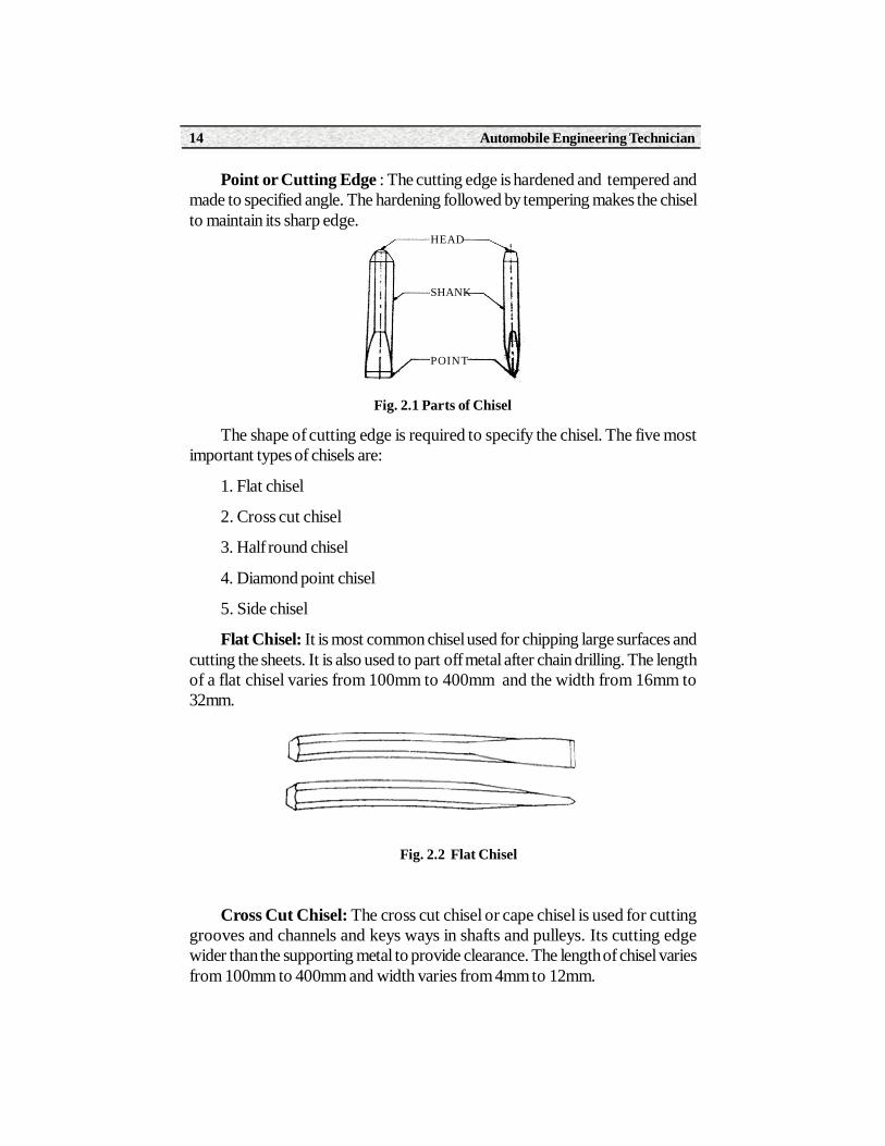
Parts of chisel:It consists of following parts
a) Head
b) Body or shank
c) Point or cutting edge
Head : The head is tapered towards top and made tough to with standhammer blows
Body or Shank : The cross section of the shank is made hexagonal oroctagonal to have grip while working.
Automobile Engineering Technician14
Point or Cutting Edge : The cutting edge is hardened and tempered andmade to specified angle. The hardening followed by tempering makes the chiselto maintain its sharp edge.
Fig. 2.1 Parts of Chisel
The shape of cutting edge is required to specify the chisel. The five mostimportant types of chisels are:
1. Flat chisel
2. Cross cut chisel
3. Half round chisel
4. Diamond point chisel
5. Side chisel
Flat Chisel: It is most common chisel used for chipping large surfaces andcutting the sheets. It is also used to part off metal after chain drilling. The lengthof a flat chisel varies from 100mm to 400mm and the width from 16mm to32mm.
Fig. 2.2 Flat Chisel
Cross Cut Chisel: The cross cut chisel or cape chisel is used for cuttinggrooves and channels and keys ways in shafts and pulleys. Its cutting edgewider than the supporting metal to provide clearance. The length of chisel variesfrom 100mm to 400mm and width varies from 4mm to 12mm.
HEAD
SHANK
POINT

Paper - I Workshop Technology 15
Fig. 2.3 Cross cut Chisel
Half Round Chisel : It is particularly useful for cutting oil ways ,cuttingcurved grooves in bearings ,bosses and pulleys .They are also used for settingover pilot holes. When a hole is to be drilled a pilot hole is drilled first.
Fig. 2.4 Half Round Chisel
Diamond Point Chisel.: Its edge is in the form of diamond used for cuttingV- grooves, cleaning corners and squaring small holes.
Fig. 2.5 Diamond Point Chisel
Side Chisel : This is used for chipping and removing the surplus metal inrectangular slots. The shank of the chisel is bent out a little side way and verticallydown again.
Automobile Engineering Technician16
Fig. 2.6 Side Chisel
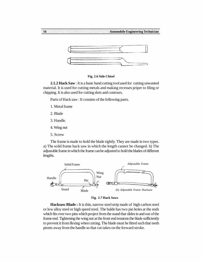
2.1.2 Hack Saw : It is a basic hand cutting tool used for cutting unwantedmaterial. It is used for cutting metals and making recesses priper to filing orchipping. It is also used for cutting slots and contours.
Parts of Hack saw : It consists of the following parts.
1. Metal frame
2. Blade
3. Handle.
4. Wing nut
5. Screw
The frame is made to hold the blade tightly. They are made in two types.a) The solid frame hack saw in which the length cannot be changed. b) Theadjustable frame in which the frame can be adjusted to hold the blades of differentlengths.
Fig. 2.7 Hack Saws
Hacksaw Blade : It is thin, narrow steel strip made of high carbon steelor low alloy steel or high speed steel. The balde has two pin holes at the endswhich fits over two pins which project from the stand that slides in and out of theframe end. Tightening the wing nut at the front end tensions the blade sufficientlyto prevent it from flexing when cutting. The blade must be fitted such that teethpionts away from the handle so that cut takes on the forward stroke.
Adjustable Frame
(b) Adjustable Frame Hacksaw
Solid Frame
Handle
Stand Blade
Pin
WingNut

Paper - I Workshop Technology 17
Fig. 2.8 Hack Saw Blade
2.1.3 FILES : File is a cutting tool with multiple teeth like cutting edgesused for producing smooth surface. The accuracy that can be acheived from0.2 to 0.05 mm.
Fig. 2.9 Parts of File
Parts of the File
1. Tang
2. Tip or point
3. Face or side
4. Edge
5. Heel
6. Shoulder
7. Handle
Woodenhandle
EdgePoint or Tip
FaceTeeth Heel Shoulder Feerule
Length of File Tang
Face
Tip Edge
Shoulder
Ferrule
Heel
Handle
Pin HoleBlade Length
250 to 200 mm
Direction of Cut Width
Pin Hole
Automobile Engineering Technician18
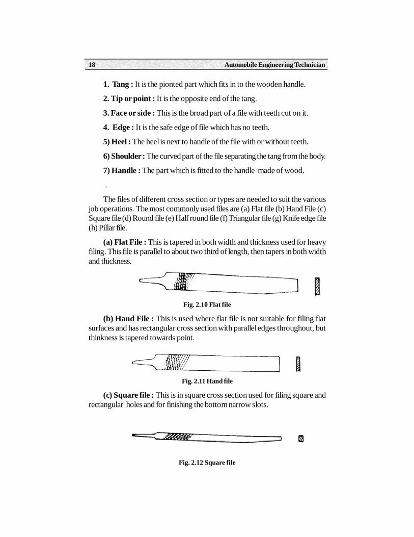
1. Tang : It is the pionted part which fits in to the wooden handle.
2. Tip or point : It is the opposite end of the tang.
3. Face or side : This is the broad part of a file with teeth cut on it.
4. Edge : It is the safe edge of file which has no teeth.
5) Heel : The heel is next to handle of the file with or without teeth.
6) Shoulder : The curved part of the file separating the tang from the body.
7) Handle : The part which is fitted to the handle made of wood.
.
The files of different cross section or types are needed to suit the variousjob operations. The most commonly used files are (a) Flat file (b) Hand File (c)Square file (d) Round file (e) Half round file (f) Triangular file (g) Knife edge file(h) Pillar file.
(a) Flat File : This is tapered in both width and thickness used for heavyfiling. This file is parallel to about two third of length, then tapers in both widthand thickness.
Fig. 2.10 Flat file
(b) Hand File : This is used where flat file is not suitable for filing flatsurfaces and has rectangular cross section with parallel edges throughout, butthinkness is tapered towards point.
Fig. 2.11 Hand file
(c) Square file : This is in square cross section used for filing square andrectangular holes and for finishing the bottom narrow slots.
Fig. 2.12 Square file
Paper - I Workshop Technology 19
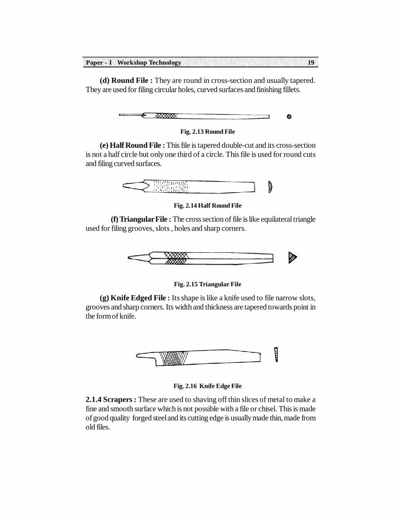
(d) Round File : They are round in cross-section and usually tapered.They are used for filing circular holes, curved surfaces and finishing fillets.
Fig. 2.13 Round File
(e) Half Round File : This file is tapered double-cut and its cross-sectionis not a half circle but only one third of a circle. This file is used for round cutsand filing curved surfaces.
Fig. 2.14 Half Round File
(f) Triangular File : The cross section of file is like equilateral triangleused for filing grooves, slots , holes and sharp corners.
Fig. 2.15 Triangular File
(g) Knife Edged File : Its shape is like a knife used to file narrow slots,grooves and sharp corners. Its width and thickness are tapered towards point inthe form of knife.
Fig. 2.16 Knife Edge File
2.1.4 Scrapers : These are used to shaving off thin slices of metal to make afine and smooth surface which is not possible with a file or chisel. This is madeof good quality forged steel and its cutting edge is usually made thin, made fromold files.
Automobile Engineering Technician20
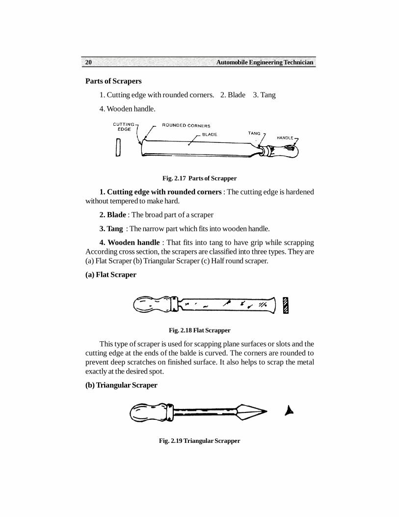
Parts of Scrapers
1. Cutting edge with rounded corners. 2. Blade 3. Tang
4. Wooden handle.
Fig. 2.17 Parts of Scrapper
1. Cutting edge with rounded corners : The cutting edge is hardenedwithout tempered to make hard.
2. Blade : The broad part of a scraper
3. Tang : The narrow part which fits into wooden handle.
4. Wooden handle : That fits into tang to have grip while scrappingAccording cross section, the scrapers are classified into three types. They are(a) Flat Scraper (b) Triangular Scraper (c) Half round scraper.
(a) Flat Scraper
Fig. 2.18 Flat Scrapper
This type of scraper is used for scapping plane surfaces or slots and thecutting edge at the ends of the balde is curved. The corners are rounded toprevent deep scratches on finished surface. It also helps to scrap the metalexactly at the desired spot.
(b) Triangular Scraper
Fig. 2.19 Triangular Scrapper

Paper - I Workshop Technology 21
It has three cutting edges and is made from old triangular files used to scrapround or curved surfaces and to remove sharp corners.
(c) Half round Scraper :
It is used for finishing curved surfaces and chamfering holes and removingburrs.
2.1.5 Drill Bits
A drill is a cutting tool for making through hole in a metal piece and usuallyit has two cutting edges set an angle with axis. It does not produce accuratehole. There are three types of drills.
(a) Flat Drill (b) Straight Fluted Drill (c) Twist Drill
(a) Flat Drill : It is a simple drill used for producing holdes in softer materialslike wood and plastic. This is made of high carbon steel and has two cuttingedges.
Fig. 2.20 Flat Drill
(b) Straight Fluted Drill : It has two cutting edges and two straight flutesused for drilling brass and non-ferrous metals.
Fig. 2.21 Straight Fluted Drill
(c) Twist Drill : This is most commonly used cutting tool in workshop. Ithas two cutting edges and two helical grooves which admits coolant and allowsthe chips to escape during the drilling. These are made of high speed steel.
Fig. 2.22 Twist Drill
Shank
Neck
Body
Flute Land
CuttingEdge
Body Clearance
Automobile Engineering Technician22
2.1.6 Reamers : A drill does not produce accurate hole and it must befinished by finishing tool called reamer. When an accurate hole with a smootherfinish a required a reamer is used. Hence the reamer can only follow the drilledhole and removes very small amount of metal to make it smooth
There are two types of reamers
(a) Hand Reamers
(b) Machine Reamers
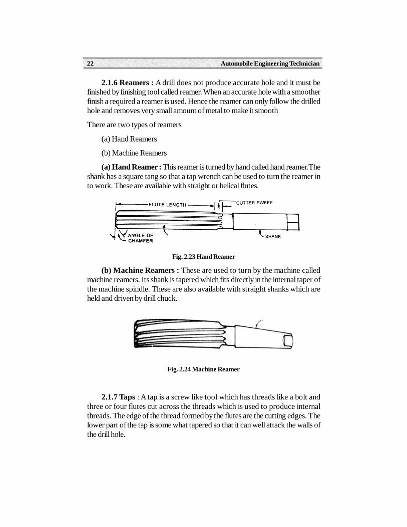
(a) Hand Reamer : This reamer is turned by hand called hand reamer.Theshank has a square tang so that a tap wrench can be used to turn the reamer into work. These are available with straight or helical flutes.
Fig. 2.23 Hand Reamer
(b) Machine Reamers : These are used to turn by the machine calledmachine reamers. Its shank is tapered which fits directly in the internal taper ofthe machine spindle. These are also available with straight shanks which areheld and driven by drill chuck.
Fig. 2.24 Machine Reamer
2.1.7 Taps : A tap is a screw like tool which has threads like a bolt andthree or four flutes cut across the threads which is used to produce internalthreads. The edge of the thread formed by the flutes are the cutting edges. Thelower part of the tap is some what tapered so that it can well attack the walls ofthe drill hole.

Paper - I Workshop Technology 23
Hand taps are usually made in sets of three (1) Taper tap (2) Second tap(3) Bottom tap.
(1) Taper Tap : In this tap about six threads are tapered and is used tostart the thread, so that the threads are formed gradually as the tap is turned intothe hole.
Fig. 2.25 Taper Tap
(2) Second tap : It is tapered back from the edge about three or fourthreads used after taper tap.It has been used to cut the threads as far as possible
Fig. 2.26 Second Tap
(3) Bottom Tap : It has full threads for the whole of its length. This is usedto finish the work prepared by the other two taps.
Fig. 2.27 Bottom Tap
2.1.8 Dies
It is a circular disc of harderned tool steel used to make external threads ona round rod or bolts with a die and stock. Die has a hole containing threads andflutes which form cutting edges. These are mainly two types
1. Solid Die 2. Adjustable Die.
1. Solid Die : It is one which has fixed dimension and cannot be adjustedfor smaller or large diameter. It is used for recutting damaged threads and maybe driven by suitable wrench.
2. Adjustable Die : It can be set to cut larger and smaller diameters. Ithas a split through one side and a slight adjustment is possible with the help ofset screw.

Automobile Engineering Technician24
Fig. 2.28 Two - Plate Die
2.1.9 Sockets
It is used for the drills whose taper is larger than spindle hole taper. It ismuch larger than sleeve. Its taper shunk conforms to the spindle hole taper andfits in to it.
2.2 Striking Tools --- Hammers
Hand hammers are also called striking tools used to strike the job. Theyare made of forged steel of various sizes and shapres to suit various purposeslike punching, chipping, marking, bending and riverting.
2.2.1 Parts of Hammer
Fig. 2.29 Parts of Hand Hammer
A hammer consists of four parts namely Face, Peen, Cheek and eye hole.
Face : It is the striking portion polished well and is given slight convexity toavoid spoilage of the surface of the metal to be hammered.
Peen : It is the other end of the head and is made into different shapes tosuit various operations.
Cheek : Middle portion of the hammer head.
Eye-Hole : It is made oval or elliptical in shape to accommodate the handle..
Face

Paper - I Workshop Technology 25
Depending upon the shape of the peen, hand hammers are classified as 1)Ball peen hammer 2) Cross peen hammer 3) Straight peen hammer.
1. Ball Peen Hammer : It has a flat striking face and ball shaped peenwhich is hardened and polished. This hammer is chiefly used for chipping andriverting.
Fig. 2.30 BallPen Hammer
2. Cross - Peen Hammer : It has wedged shape peen across the eye. Itis used for bending, stretching, hammering into shoulders.
Fig. 2.31 Cross-Pen Hammer
3. Straight Peen Hammer : This is similar to cross peen hammer exceptthat the peen in this case is parallel to eye. It is used for stretching and peeningthe metal.
Fig. 2.32 Straight Peen Hammer
4. Soft Hammer or Mallet : These are soft hammers used give lightblows where the work surface must not be damaged . They are made of eitherrubber, plastic or wood.

Automobile Engineering Technician26
Fig. 2.33 Soft Hammer
2.3 Holding Devices or VicesIn most of the metal cutting operations quite a large number of forces will
be involved. So it is necessary that the work must be secured highly so that itdoes not move when subjected to the cutting forces. Therefore, holding the jobis an important aspect of all metal cutting operations. A vice is a work holdingdevice used to grip the job tightly. Different types of vices are used for variouspurposes. They include
a. Bench vice
b. Pipe vice
c. Hand vice
d. Pin vice
e. Tool maker’s vice
2.3.1 Bench vice
This is most commonly used tool forholding the work. It has two jaws one ofwhich is fixed to the bench and other slideswith the aid of square screw and a box nutarrangement.The outer end of screw carriesa handle, and a collar prevents the screw fromcoming out of the unit while rotating.Thesliding jaw moves close to the fixed jaw tohold the work and the tightening force isexerted by further rotation of handle.Theworking faces of jaws are serrated to giveadditional grip.
Sliding JawFace
Body
Handle
Fig.2.34 Bench Wise

Paper - I Workshop Technology 27
2.3.2 Pipe Vice
It is generally used for holding round sections ,tubes and pipes etc.It hastwo serrated jaws,one is fixed and the is moved by rotation of handle.It is usedin lumbing work and it grips the circular objects at four points on its surfaces.
Fig. 2.35 Pipe Vice
2.3.3 Hand vice
It is used for gripping small objects like screw, rivets, keys when they areinconvenient to hold by the bench vice. It has two legs made of Mild steel whichholds two jaws at the top and are hinged together at the bottom .A spring isprovided between these legs to keep them away. The work is held between theserrated jaws by means of a wing nut and screw.
Fig. 2.36 Hand Vice
2.3.4 Pin vice
It is used for holding small parts such as wires ,nails and pins. It consists ofthree jaw self centering chuck which is operated by turning the handle to holdwork.
Fig. 2.37 Pin Vice

Automobile Engineering Technician28
2.3.4 Tool makers vice
It is a small vice made of mild steel used for holding small jobs whichrequires fitting or drilling.It is used by tool and die makers and silver smiths tohold small jobs.
Fig. 2.38 Tool Maker’s Vice
2.4 Marking Tools1. Surface Plate 2. V - Block
3. Scribers 4. Angle plate
5. Punches 6. Try - Square
2.4.1 Surface Plate
Surface plate is made of grey cast iron of solid design. It is used for testingthe flatness of work and also used for marking-out the work. A surface plate hasa surface of proved flatness. When used for testing flatness,the top of the plateshould be coated with their layer of red lead in oil. The surface to be tested mustbe cleaned, then place in contact with the plate and moved about. If it is reasonablyflat, subsequent examination will show spot of blue or red all over the surface.
Fig. 2.39 Surface Plate
2.4.2 V - Block : It is made of hardened steel with V-shaped grooves onthe top and botton,and rectangular slots on two sides for the location of clamps.Roundly shaped workpieces which are to be marked or drilled are placed onV-supports. In this way, they are firmly supported in a horizontal position andcannot rotate easily.
Movable Jaw Screw
Body
HandleFixed Jaw

Paper - I Workshop Technology 29
Fig. 2.40 Surface Plate
2.4.3 Scribers : It is made of tool steel with hardened and tamperedpoints and knurled on the body to provide grip. Scriber is used for makingstraight lines on metal surface with the aid of steel rule, try square and templates.The bent end is used to scratch line in places where the straight end cannotreach. The ends are sharpened on an oil stone when necessary.
Fig. 2.41 Single point Scriber Fig. 2.42 Double point Scriber
2.4.4 Angle plate : This is used in conjunction with the surface plate forsupporting work in the perpendicular position. It is madeof grey cast iron hastwo plane surfaces at right angles to each other. It has various slots in it to enablethe work to be held firmly by bolts and clamps.
Fig. 2.43 Angle Plate

Automobile Engineering Technician30
2.4.5 Punches : Punches are used in a bench work for marking out work,locating centres, etc in permanent manner. It is made of tool steel, hardenedand tempered . The shank is knurled to provide grip.
Punches are two types
1. Prick punch 2. Centre punches.
Prick punch is sharply pointed tool used for marking small dots along thelayout lines in order to make them last longer. Centre punch has an angle morethan abtuse and used to mark the centres of holes to be drilled.
Fig. 2.44 Prick Punch Fig. 2.45 Centre Punch
2.4.6 Try Square : It is made of steel and consist of a blade and a stockmade in one piece set at right angle to each other. It is used to test trueness ofmutually perpendicular surfaces and for making straight lines at right angle toeach other.
Fig. 2.46 Try Square
BLADE
STOCK

Paper - I Workshop Technology 31
2.5 Miscelleneous Tools
In addition to the above tools, the following tools are widely used in fitting.
1) File Card 2) Screw driver
3) Spanner 4) Pliers
1. File Card
It is the short wire brush used to remove small chips called pins, and toclean the file. While filing these chips are deposited between the teeth of filewhich reduces cutting ability and casuing scratches on work piece.
Fig. 2.47 File Card
2. Screw Driver
Screw driver is used for tightening and loosening the screws. It is made invariety of shapes to suit various job operations.
Fig. 2.48 Screw Driver
3. Spanners
These are also called wrenches, are used for tightening or loosening nutsand bolts. The following types of spanners are widely used in fitting.
a. Single end Spanner
b. Double end Spanner
c. Adjustable Spanner
d. Box Spanner

Automobile Engineering Technician32
Fig. 2.49 Spanner
4. Pliers
These are used for holding small jobs which are difficult to held by hand.They are used for bending and cutting the wires. The following types of pliersare most common.
1. Cutting pliers 2. Nose Pliers
Fig. 2.50 Cutting Plier Fig. 2.51 Nose plier
2.6 Checking and Measuring InstrumentsMeasuring Instruments :
a) Steel rule b) Calipers
c) Depth gauge d) Vernier Calipers
e) Micrometer f) Gauge block
a) Steel Rule
It is used for direct measurement of length which do not require greataccuracy and also used to transfer the measurements from steel rule to calipers.These are available in 150 mm or 300 mm in length.
Fig. 2.52 Steel Rule

Paper - I Workshop Technology 33
b. Calipers
These are used for measuring and transferring the inside or outsidedimensions for components. These are also used for comparing the sizes withexisting standards. The following types of calipers are most widely used inworkshops
1. Outside Calipers 2. Inside Calipers
1. Outside Calipers
It is used for measuring outside dimensions of cylindrical shapes and thethickness of metal pieces. It has two steel legs bent inwards.
Fig. 2.53 Outside Calipers
2. Inside Calipers
It is used to measure the diameter of holes and width of key ways orrecesses. Its legs are bent outwards.
Fig. 2.54 Inside Calipers
3) Depth Gauge
It is used to measure the bling holes, slots, recesses and height of projections.

Automobile Engineering Technician34
Fig. 2.55 Depth Guage
4. Vernier Calipers
These are widely used for precision measurement of length, thickness, depthand inside and outside diameters. With vernier caliper we can achieve accuracyupto 0.02 mm.
Fig. 2.56 Vernier Calipers
5. Micrometer
Micrometer is a precision tool used to measure external or internal dimensionssuch as diameters and thickness, with an accuracy upto 0.01 mm.
Fig. 2.57 Screw Thread Micrometer

Paper - I Workshop Technology 35
Fig. 2.58 Inside Micrometer
6. Gauge Block
They are used to check the accuracy of gauges to set comparators, sinebars and to make machine tool setups.
Fig. 2.59 Guage Block
7. Dividers
These are used for transferring dimensions and scrubing circles and arcs onwork surface. These are also used for dividing straight and curved lines.
2.7 Drilling MachinesDrilling is a process of making holes in a work piece and is carried out by
driving a rotating tool called “drill” into a rigidly held work peice. To accomplishthe drilling two things are required i.e. drilling macine and drilling tools. A drillingmachine is used for drilling holes. However it can perform operations other thandrilling such as reaming, boring, lapping etc.
Types of Drilling Machine
1) Portable drilling machine
Spindle(Ext-Rod)
Barrel Thimble
Distance
Measured
Handle
Vernier Slide Fine AdjustmentBeam
Lock ScrewsVernier ScaleWork

Automobile Engineering Technician36
2) Sensitive drilling machine
3) Radial drilling machine
4) Upright drilling machine
5) Gang drilling machine
2.7.1 Sensitive Drilling MachineIt isa small drilling machine is mounted on a bench in which feed is hand
operated, and the cutting force applied is determined by sense of feel of theoperator. The parts of sensitive drilling machine as shown below. It consists of avertical column, a work table, head supporting the motor and driving mechanism,and a vertical spindle for driving and rotating the drill.
The work is mounted on the work table which may be raised or loweredby the clamp to accomodate work pieces of different sizes. The driving mehanismconsists of V-belt drive from machine spindle to drill spindle. Three or fourspeed stepped cone pulley is provided to give various speed ranges. The spindleis designed and mounted in a sleeve such that the spindle rotates andsimultaneously moves up and down to provide feed for drill. This is achieved bya rack and pinion mechanism.
Fig. 2.60 Sensitive Drilling Machine

Paper - I Workshop Technology 37
2.7.2 Radial Drilling Machine
Radial drilling machines are used for drilling heavy work pieces, where it iseasier to move the drill rather than work and specially for the jobs where highdegree of accuracy is required. It consists of base, column, radial arm, drill headand driving mechanism. The arm of radial drilling machine can be swing aroundthe column to any position and angle. A wide range of spindle speeds, togetherwith automatic feed of the spindle, makes the radial drilling machine suitable fordrilling large castings. For lowering or raising the radial arm, a separate motor isprovided. The work can be firmly champed on the table having T-slots. Thetable is fixed to the base. The radial arm and the spindle can be adjusted withoutdisturbing the work setting.
Fig. 2.61 Radial Drilling Machine
2.8 Drill FittingsThe following devices are used for holding the drills.
a. Drill Chuck : It is designed to hold straight shank drills of different sizes.The jaws of the chuck are tightened around the drill by means of drill chuck key.. These drill chucks have standard taper shanks.
b. Machine spindle : These have morse taper holes. Standard taper drillsare directly fitted in the spindle. The drill may be removed by driving the drift..

Automobile Engineering Technician38
Fig. 2.62 Drill Chuck Fig. 2.63 Machine Spindle
c. Sleeve : It is used to hold the taper shank drills whose taper is less thantaper hole of the spindle.
Fig. 2.64 Sleeve Fig. 2.65 Socket
d. Socket : It is used for the drilling whose taper is larger than spindle holetaper. It is much longer than sleeve. Its taper shank confirms to the spindle holetaper and fits into it.
2.9 Drilling OperationsThe following operations are generally performed on drilling machine.
a) Drilling b) Reaming c) Boring
Taper Shank
Taper hole

Paper - I Workshop Technology 39
d) Counter boring e) Counter sinking f) Tapping
a) Drilling : It is the process of making cylindrical hole by rotation ofcutting tool.
b) Reaming : It is the process of making a hole smoothly and accuratelyby the tool called reamer.
c) Boring : It is the operation of enlarging a drilled hole to bring it torequired size by using single point cutting tool.
d) Counter boring : This operation is used for enlarging only to a certaindepth of already drilled hole in order to maintain alignment and true concentricityof the counter bored hole with the previously drilled hole and the tool is providedwith a pilot at its bottom.
e) Counter Sinking : It is the operation of enlarging the end of a drilledhole to give a conical shape for a short distance. This is done for providing aseat to the counter sunk heads of screws.
f) Tapping : It is the operation of cutting internal threads by using a cuttingtool called tap. In order to tap the hole, a special tapping chuck must be used.
Fig. 2.66 Drilling Machine Operations
Drilling Reaming Boring
Counter Sinking Tapping

Automobile Engineering Technician40
Summary1. Fitting is the process of assembling various parts manufactured in the
machine shop.
2. In fitting the hand tools are classified as cutting tools, marking tools,striking tools,holding tools, measuring and checking instruments.
3. Chisels are used to cut thin sheets and to remove excess material in theform of layers
4. Hacksaw is abasic hand cutting tool used to remove excess metal fromthe job
5. Files are used to remove excess metal from the job in the form of pow-der to make it smooth
6. Scrapers are used to remove excess metal in form of thin layers at se-lected spots to make it truly flat surface
7. Drilling is the process of making circular holes on the metal piece byrotating the tool against work piece
8. Reamer is a tool used to finish the already drilled hole on cylindricalholes
9.Tap is acutting tool used to cut internal threads and dies are used to cutexternal threads on the cylindrical rods and pipes
10. Striking tools are hammers used to strike the work or tool
11. Holding devices are used to hold work tightly to prevent slipping duringcutting operations.
Activity1. A learner should collect L-shape M S flat.
2. A learner should collect T-shape MS flat.
Short Answer Type Questions1. What is the use of a file.
2. What is the purpose of chisel.
3. Define scrappers.
4. Differentiate tap and die.

Paper - I Workshop Technology 41
5. What are srtiking tools.
6. Define drilling and reaming.
7. What is the importance of holding devices.
8. Name different types of drilling machines.
Long Answer Type Questions1. Define file and explain about any four files with sketch.
2. Explain about bench vice with naet sketch.
3. Define chisel and Explain about any two.
OJT Type Question1. Prepare U,V,L& T Shapes from a given MS Flat

Automobile Engineering Technician42
Learning ObjectivesOn completion of this unit, a learner will be able to
• List out metals used for sheet metal work.
• List and explain various tools used in sheet metal work.
• Explain various sheet metal operations.
• List and explain various sheet metal joints commonly used.
• Explain various fastening methods.
3.0 IntroductionSheet metal work is generally regarded as the working of metal from 16
SWG down to 30 SWG with hand tools and simple machines into variousforms by cutting ,forming into shapes and joining. Each guage designates a definitethickness.Higher the gauge number and lesser the thickness. The commonexamples of sheet metal work are pipes, boxes, funnels, photoframes, buckets,and cans etc. In sheet metal work the knowledge of geometry, mensuration andproperties of metal are most important for preparation of specific object.
Sheet Metal Work
3UNIT
Paper - I Workshop Technology 43
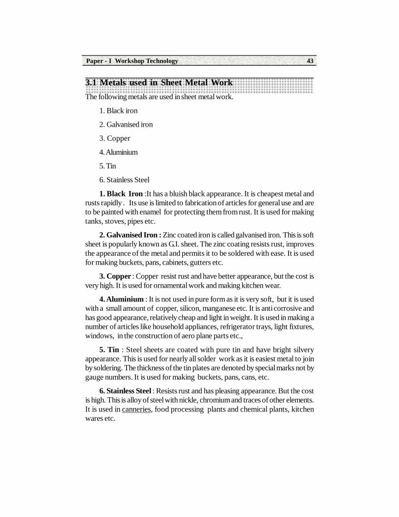
3.1 Metals used in Sheet Metal WorkThe following metals are used in sheet metal work.
1. Black iron
2. Galvanised iron
3. Copper
4. Aluminium
5. Tin
6. Stainless Steel
1. Black Iron :It has a bluish black appearance. It is cheapest metal andrusts rapidly . Its use is limited to fabrication of articles for general use and areto be painted with enamel for protecting them from rust. It is used for makingtanks, stoves, pipes etc.
2. Galvanised Iron : Zinc coated iron is called galvanised iron. This is softsheet is popularly known as G.I. sheet. The zinc coating resists rust, improvesthe appearance of the metal and permits it to be soldered with ease. It is usedfor making buckets, pans, cabinets, gutters etc.
3. Copper : Copper resist rust and have better appearance, but the cost isvery high. It is used for ornamental work and making kitchen wear.
4. Aluminium : It is not used in pure form as it is very soft, but it is usedwith a small amount of copper, silicon, manganese etc. It is anti corrosive andhas good appearance, relatively cheap and light in weight. It is used in making anumber of articles like household appliances, refrigerator trays, light fixtures,windows, in the construction of aero plane parts etc.,
5. Tin : Steel sheets are coated with pure tin and have bright silveryappearance. This is used for nearly all solder work as it is easiest metal to joinby soldering. The thickness of the tin plates are denoted by special marks not bygauge numbers. It is used for making buckets, pans, cans, etc.
6. Stainless Steel : Resists rust and has pleasing appearance. But the costis high. This is alloy of steel with nickle, chromium and traces of other elements.It is used in canneries, food processing plants and chemical plants, kitchenwares etc.

Automobile Engineering Technician44
3.1.1 Sheet Metal Hand Tools
A large number of hand tools used by sheet metal workers. Some of theimportant tools used are given below.
1. Measuring tools
(a) Steel rule
(b) Folding rule
(c) Circumference rule
(d) Vernier Calipers
(e) Micrometer
(f) Sheet metal guage
2. Straight edge
3. Scriber
4. Divider
5. Trammel point
6. Chisel
7. Punches
8. Hammers
9. Snips or Shears
10. Pliers
11. Stakes
12. Groovers
13. Rivetsets
14. Soldering Iron
3.1.2. Measuring Tools(a) Steel Rule : It is used for measuring and layouting small works with an
accuracy upto 0.5 mm.

Paper - I Workshop Technology 45
Fig. 3.1 Steel rule
(b) Folding Rule : It is used for measuring and laying out larger workpieces accuracy upto 0.5 mm
Fig. 3.2 Folding rule
(c) Circumference Rule : It is used to find out directly the circumferenceof a cylinder. One of the edge is marked with diameters and the values ofcircumference corresponding to each diameter is marked in the other edge.
Fig. 3.3 Circumference Rule
(d) Vernier Caliper : It is used for measuring dimensions upto 0.02 mm.
Fig. 3.4 Vernier Caliper

Automobile Engineering Technician46
(e) Micro Meter : This is used to measure the thickness of the metalsheet accurately upto 0.01 mm.
Fig. 3.5 Micrometer
(f) Sheet Metal Guage : This is used to measure the thickness of thesheet.
Fig. 3.6 Sheet Metal Guage
(2) Straight Edge : It is a steel bar has one long edge is bevelled andcomes in variety of lengths. It is used for drawing long straight lines.
Fig. 3.7 Straight Edge
(3) Scriber : It is a steel wire and its one end is sharply pointed andhardened to mark layout lines on the sheet metal.
Straight Edge
Work
Scriber

Paper - I Workshop Technology 47
Fig. 3.8 Single point Scriber Fig. 3.9 Double point Scriber
(4) Divider : Dividers are used to draw circle or arcs on sheet metal and todivide the lines into two equal parts.
Fig. 3.10 Divider
(5) Trammel Point : These are used to describe large circles and arcsbeyond the limits of dividers.
Fig. 3.11 Trammel point
(6) Chisels : These are used to cut sheets, rivets, bolts and for chippingoperations.
Fig. 3.12 Chisels
Automobile Engineering Technician48
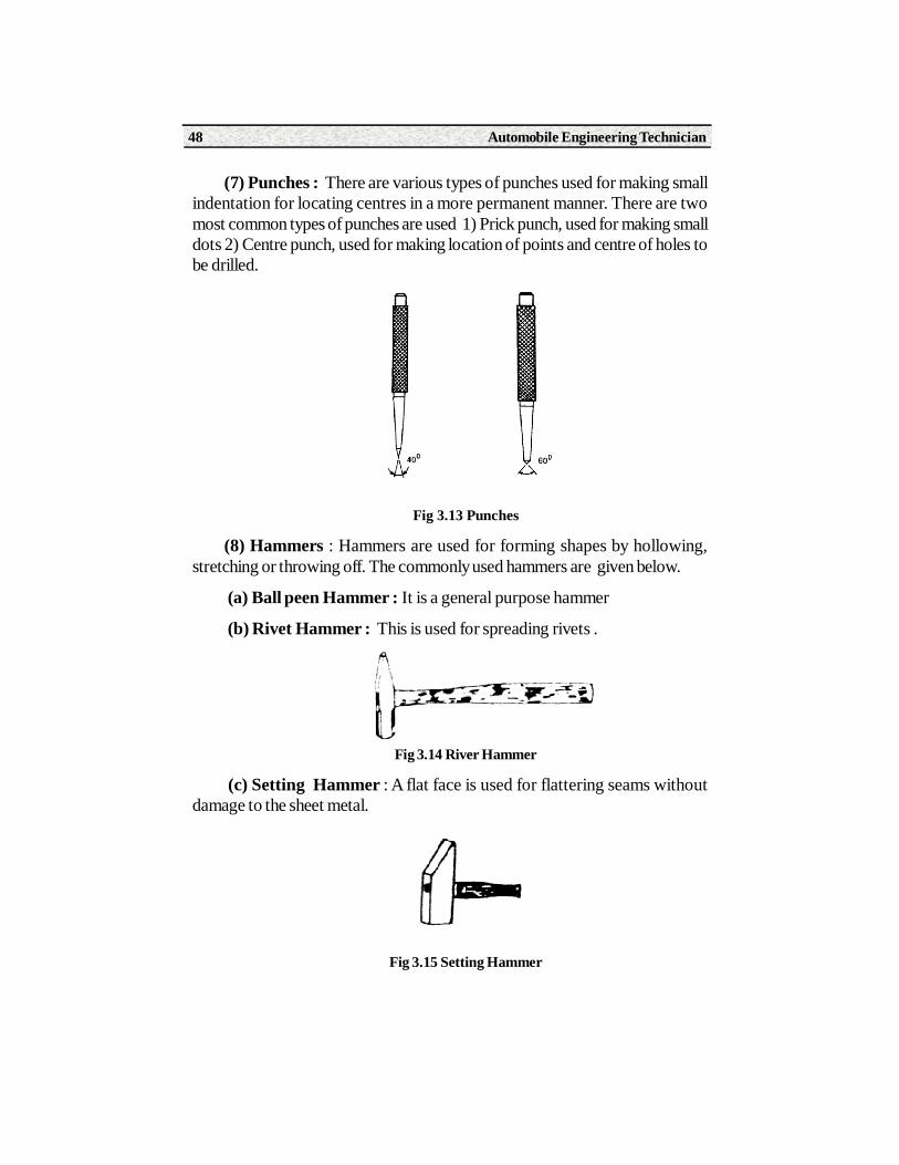
(7) Punches : There are various types of punches used for making smallindentation for locating centres in a more permanent manner. There are twomost common types of punches are used 1) Prick punch, used for making smalldots 2) Centre punch, used for making location of points and centre of holes tobe drilled.
Fig 3.13 Punches
(8) Hammers : Hammers are used for forming shapes by hollowing,stretching or throwing off. The commonly used hammers are given below.
(a) Ball peen Hammer : It is a general purpose hammer
(b) Rivet Hammer : This is used for spreading rivets .
Fig 3.14 River Hammer
(c) Setting Hammer : A flat face is used for flattering seams withoutdamage to the sheet metal.
Fig 3.15 Setting Hammer

Paper - I Workshop Technology 49
(d) Raising Hammer : This hammer is used for denting the metal downto shape.
Fig. 3.16 Raising hammer
(e) Mallet : Mallets are used where ever light blows are required. Thesemay be made of either fiber, plastic, wood or rubber.
Fig. 3.17 Mallet
(9) Snips or Shears : These are heavy scissors used for making straightor circular cuts. It is used only to cut 20 guage or thinner metals. The mostcommon types of snips are a) Straight snips, used for straight cuts, b) Bentsnips, used to make curved cuts.
Fig. 3.18 Straight Snips
(10 ) Pliers : There are two pliers which are used in sheet metal work.They are flat nose plier and round nose plier. Flat nose pliers are used forforming and holding work while round nose pliers are used for holding andforming in to various shapes.
Fig. 3.19 Pliers
Automobile Engineering Technician50
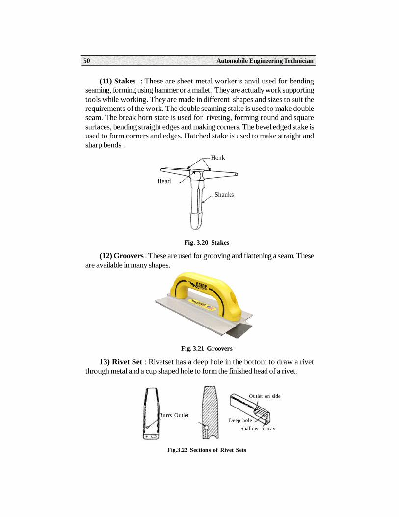
(11) Stakes : These are sheet metal worker’s anvil used for bendingseaming, forming using hammer or a mallet. They are actually work supportingtools while working. They are made in different shapes and sizes to suit therequirements of the work. The double seaming stake is used to make doubleseam. The break horn state is used for riveting, forming round and squaresurfaces, bending straight edges and making corners. The bevel edged stake isused to form corners and edges. Hatched stake is used to make straight andsharp bends .
Fig. 3.20 Stakes
(12) Groovers : These are used for grooving and flattening a seam. Theseare available in many shapes.
Fig. 3.21 Groovers
13) Rivet Set : Rivetset has a deep hole in the bottom to draw a rivetthrough metal and a cup shaped hole to form the finished head of a rivet.
Fig.3.22 Sections of Rivet Sets
Head
Honk
Shanks
Burrs OutletDeep hole
Shallow concav
Outlet on side

Paper - I Workshop Technology 51
(14) Soldering Iron : It is used to join two pieces of sheet metal by softsoldering (al alloy of tin and lead). Soft solder is transferred to the joint bymeans of soldering iron.
Fig. 3.23 Types of Soldering Irons
3.2 Sheet Metal OperationsThe major types of sheet metal operations are given below.
(1) Shearing
(2) Bending
(3) Drawing
(4) Squeezing
(1) Shearing
Shearing is the process of cutting across a sheet or strip. The various shearingoperations include
(a) Cutting off (b) Parting
(c) Blanking (d) Punching
(e) Piercing (e) Slitting
(g) Trimming
a. Cutting Off : It is the operation of shearing the piece from sheet metalwith a cut along a single line.
b. Parting : This means that the strip is removed between the two pieces topart them.
c. Blanking : It is the operation of cutting the flat sheet to the requiredshape and size using punch and die.
(a) Straight Iron
(b) Hatchet Iron

Automobile Engineering Technician52
d. Punching : It is the operation of making only circular holes in a sheetmetal.
e. Piercing : It is the operation of making a hole of any shape in a sheetmetal by punch and die.
f. Slitting : It is the operation of cutting the sheet metal in a line along thelength.
g. Trimming : It is the operation of finishing the edges of a part by removingexcess metal around it.
2. Bending : It is the folding operation by using suitable tools. It may bedone over stakes. The common forms of bending the sheet metal is single bendand double bend etc.
3. Drawing :It is the process of producing thin walled hallow or vesselshaped parts from the sheet metal. Again this process can be divided into twotypes. a) Deep drawing and shallow drawing..In deep drawing, the height of thecomponent is greater than the diameter or width. In shallow drawing the heightof the component is less than the diameter or width.
Fig. 3.24
(4) Squeezing : It is the quick and widely used method. The operationinvolves severe cold deformation and it requires a greater amount of pressureto deform the metal at cold state.
The most commonly used squeezing operation are sizing, coining, hobbing,riveting.
(a) Sizing : This operation is used for surfacing or flattening. A special dieis needed for every job.
(b) Coining : This is a process of making impressions or raising of imagesby a plastic flow by using a punch and die.

Paper - I Workshop Technology 53
(c) Hobbing : It is the process of producing cavities into surface of materialby pressing with a special punch called hub.
(d) Riveting : It is the process of fastening the two metal sheets by insertingmetal pin in to the sheets and spreading out by hammering to form the rivethead.
3.3 Sheet Metal Joints3.3.1 Hem and Seam Joints
(1) Hem Joint : Hem is an edge or border made by folding. It strengthensthe edges and eliminate the sharp edges. Hems are three types a) Single hem b)Double hem c) Wired edged hem
(a) Single Hem : It is made by single folding of the edge of sheet metal.
Fig. 3.25 Single Hem
(b) Double Hem : It is made by folding the edge over twice to make itsmooth. It provides much greater strength than single hem.
Fig. 3.26 Single Hem
c) Wired Edged Hem : It consists of holding a piece of sheet metal arounda wire of given diameter.

Automobile Engineering Technician54
Fig. 3.27 Wired Hem
(2)Seam Joint : It is the joint formed by two edges of sheet metal. Theprocess of joining the edges are called seaming. Different kinds of seams aregiven below. a) Lap seam b) Groove seam c) Single seam d) Double seam e)Dovetail seam f) Flanged Seam
a) Lap Seam : It is a simple type of seam which consists of lapping theedgeof one sheet over the other and the joint is made by soldering or riveting.
Fig. 3.28 Lap Seam
(b) Grooved Seam : It is made by hooking two single hems together
Fig. 3.29 Grooved Seam
(c) Single Seam : Single seam is used to join a bottom to vertical bodiesof various shapes.
Sheet
Hammer
Wire

Paper - I Workshop Technology 55
Fig. 3.30 Single Seam
(d) Double Seam : It is similar to single seam with the difference that itsformed edges bent upwards against the body.
Fig. 3.31 Double Seam
(e) Flanged Seam : It is used to join the bottom of a container to its body.
(f) Dovetail Seam : It is used to join sections such as one pipe to anotherpipe or a sheet to pipe It consists of narrow strips of metal which are formed byslitting the end of pipe.
Fig. 3.33 Dovetail Seam
Fig. 3.32 Flanged Seam

Automobile Engineering Technician56
3.3.2 Fastening Methods
The following fastening methods are widely adopted in sheet metal work.
(a) Riveting (b) Soldering (c) Brazing (d) Welding.
(a) Riveting : It is a permanent fastening method by using rivet. Rivetconsists of head, shank and tail are generally made of same metal as the partsthat are being joined. The required holes must be either punched or drilled beforeriveting.
Fig. 3.34 Rivet Sets
(b) Soldering : It is the process of joining two or more metal pieces bymeans of an alloy. This alloy is called solder made of lead and tin. The meltingpoint of solder is less than the metal to be joined. For soldering, the base metalis heated by soldering iron which also melts solders and flux. the flux (zinc chloridepaste) is used to dissolve the oxide film on the surface and also prevents oxidationduring soldering. The molten solder fills the space between mating surfaces. Itsolidifies and forms a strong joint.
Fig. 3.35 Solder
Hammer BlowHammer Blow
a) Drawing Rivet Set b) Shaping Rivet Set c) Forming Rivet
Solder Solder Iron

Paper - I Workshop Technology 57
c) Brazing : It is similar to soldering, but it gives much stronger joint. Themajor difference is that use of a harder filler material called spelter and its meltingpoint is higher than solder., but lower than the metal being joined. In brazingoperation the two metal pieces are to be joined must be cleaned. Flux (Borax)is applied on the joint and heated to a temperature just above the melting pointof the spelter. The liquid spelter is distributed between the surfaces by capillaryaction. After solidification it forms strong joint.
d) Sport Welding : The spot welding is used for joining the sheets byapplication of heat and pressure at specific locations called spots. In this, thesheets to be joined together are held between two electrodes at required locatedsports. Normally a high amperage current and low voltage is passed throughelectrodes causing local heating at that spots. The pressure applied on theelectrodes squeezes the sheet metal at various locations thus joining the twosheets together to form a joint.
Fig. 3.36 Sport Welding
Summary1. Sheet metal work is the process of making useful articles for household
as well as industrial.
2. Commonly used sheet metals are black iron, galvonised iron, copper,aluminium, stainless steel etc.
3. Tools used in sheet metals are measuring tools and operational tools.
4. Most common sheet metal operations are shearing, bending, drawing,squeezing etc.
5. Important fastening methods in sheet metal are riveting, soldering, brazingand spot welding.
Spot WeldTransformer
1,2 Electrodes
3. Movable Arm
4. Fixed Arm
5. Frame

Automobile Engineering Technician58
Activity1. A learner should collect funnel madeof sheet metal.
2. A learner should collect a square tray
3. A learner should collect riveted joint sheet metal piece.
4. A learner should collect soldered joint sheet metal piece.
Short Answer Type Questions1. Name different tools used in sheet metal work.
2. Define Seam in sheet metal work.
3. What is the purpose of mallet ?
Long Answer Type Questions1. Explain about any four important sheet metal operations.
2. Explain different sheet metal joints with sketches.
3. Explain brazing and soldering.
OJT / Related Questions1. Prepare a rectangular tray from a given G.I . sheet
2. Prepare a funnel of given dimensions from G.I. Sheet metals.
3. Join the given two sheet metal pieces by soldering.
4. Join the given sheet metal pieces by riveting.

Learning ObjectivesOn completion of this unit a learner will be able to
• Explain various hand tools used in carpentry
• Know the importance of holding devices
• Explain about various carpentry joints
• Know the different carpentry processes
4.0 Introduction Carpentry deals with the processing of wood to obtain desired shapes
and sizes. Strictly speaking carpentry deals with all works of a carpentry suchas roofs, floors, partitions etc of a buildings. While joining deals with the makingof doors, windows, cupboards, dressers stairs and all interior fitments for abuilding.
Timber is the basic material used for any type of wood work. It is availablein a wide choice of weights, strengths, colours and textures. Wood having goodmachining characteristics.
Carpentary
4UNIT
Automobile Engineering Technician60
4.1 Markings and Measuring Tools
Marking is one of the most important features of wood work and the jobaccuracy depends upon marking and measuring. These tools are used in woodwork for marking, measuring and checking the work at various stages.
Measuring Tools
The following tools are commonly used in wood work.
1. Steel rule
2. Wooden folding rule
3. Steel tape
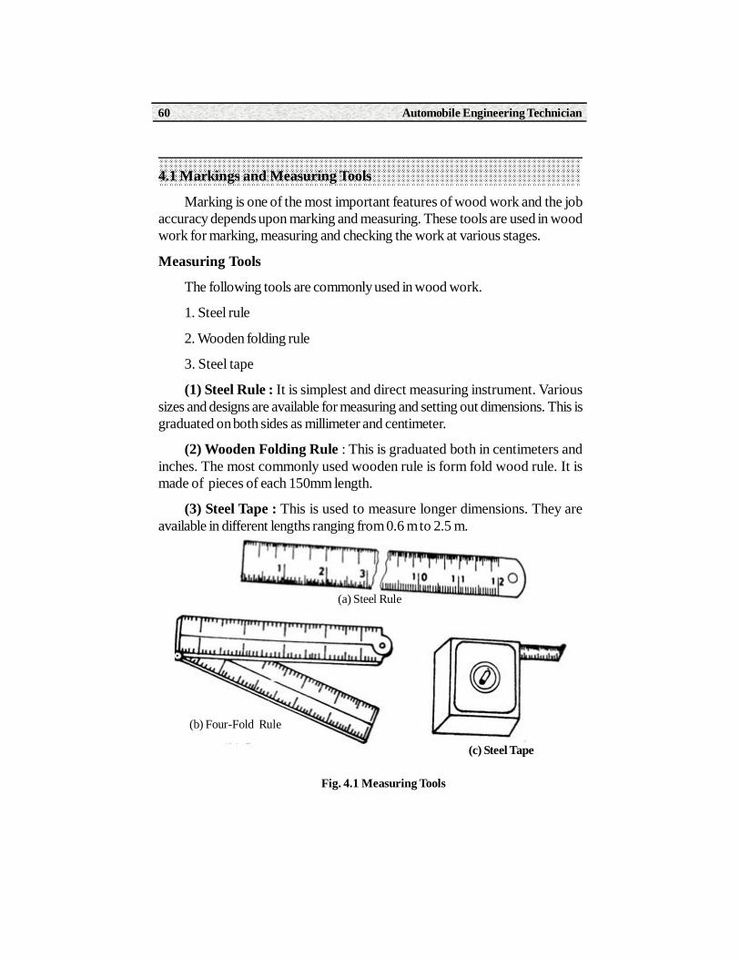
(1) Steel Rule : It is simplest and direct measuring instrument. Varioussizes and designs are available for measuring and setting out dimensions. This isgraduated on both sides as millimeter and centimeter.
(2) Wooden Folding Rule : This is graduated both in centimeters andinches. The most commonly used wooden rule is form fold wood rule. It ismade of pieces of each 150mm length.
(3) Steel Tape : This is used to measure longer dimensions. They areavailable in different lengths ranging from 0.6 m to 2.5 m.
Fig. 4.1 Measuring Tools
(a) Steel Rule
(b) Four-Fold Rule
(c) Steel Tape

Paper - I Workshop Technology 61
Marking Tools
The following tools are used for marking in wood working.
(1) Straight Edge
(2) Try square
(3) Marking guage
(4) Divider
(5) Marking knife
(1) Straight Edge : The straight edge is a machined flat piece having truelystraight and parallel edges. One of the longitudinal edge is generally madebevelled. It is used for testing trueness of surface and straightness of edges.
Fig. 4.2 Straight Edge
(2) Try Square : This is used for marking and testing angles of 90o. Itconsists of a steel blade, rivetted to a hard woodstock which has a protectivebrass plate on the working surface.
Fig. 4.3 Try square
Work
Straight Edge
Scriber
Bevelled Edge

Automobile Engineering Technician62
(3) Mitre Square : It is used for marking and testing 45o. It consists of asteel blade fitted in a wooden or metal stock at an inclination of 45o withhorizontal.
Fig. 4.4 Mitre Square
(4) Marking Knife : All the dimensional lines marked with pencil are cutwith marking knife. It has a chisel edge at one end and sharp point at other end.It is made of steel.
Fig. 4.5 Marking Knife
(5) Marking Guage : It is commonly used when absolute accuracy isrequired. It has a stem with a sharp point pin at one end. It is used to cut linealong the grains and parallel to an edge. The distance can be adjusted by slidingthe stock.
Fig. 4.6 Marking Guage
(6) Divider : It has two pointed legs and hardened to prevent wear. It isused for transferring dimensions and scribing curves or circles.

Paper - I Workshop Technology 63
Fig. 4.7 Divider
4.2 Cutting ToolsCutting tools are used to cut the wood to approximate size. The following
cutting tools are used in carpentry.
(a) Saw or Hand Saw : The saw is most commonly used cutting tool inwood working section. All saws used in wood work essentially consists of twomain parts - the blade which carries the cutting teeth and the handle used forholding during the cutting operations to apply pressure. The classification ofsaws is according to their teeth and the direction of grains of the wood to be cut.
Fig. 4.8 Hand Saw
The following types of saws are used in wood working.
(b) Rip Saw : Rip saw is used to cut the wood along the grains. The cuttingaction starts from near the tip and gradually the whole length.
Fig. 4.9 Rip Saw

Automobile Engineering Technician64
(b) Crosscut Saws : It is used for cutting the wood across the grains. Theaction of the teeth is that of a series of knives which sever the fibre and force outthe waste wood in the form of saw dust.
Fig. 4.10 Cross-cut saw
(c) Panel Saw : It has a fixer blade and is used for fine work, mostly on thebench. This is often used for ripping as well as cross cutting. The teeth haveslightly more hook than those of a cross cut saw.
(d) Tenon Saw : This saw is mostly used for cross-cutting when a fine andmore accurate finishing is required. The blade is very thin and reinforce with arigid steel back.
Fig. 4.11 Panel Saw
(e) Dovetail Saw : It is a smaller version of tenon saw, this saw is usedwhere the greatest accuracy is needed and fine shallow cuts are to be needed.
Fig. 4.12 Dovetail Saw
(f) Bow-Saw : It has a narrow blade which is held in tension by twisting thestring with a small wooden lever. These saws are used for cutting quick curves

Paper - I Workshop Technology 65
and the handles can revolve in their sockets. The blades can be adjusted to anydesired position when in use.
Fig. 4.13 Bow Saw
(g) Key Hole Saw : It is smallest saw. It has a tapered blade fixed into thehandle by screws. It is used for cutting key holes and is very useful for internaland intricate work.
Fig. 4.14 Key hole Saw
Chisels : A fairly large number of chisels are used in wood work for cuttingin different manners to produce desired shapes and cavities. The chisel consistsof these parts irrespective of their size and use. The common types of chisels areused in carpentry work are the following.
Fig. 4.15 Chisel
Handle
Brass
TangShoulder
Neck
Blade
Cutting Edge
Handle

Automobile Engineering Technician66
(i) Firmer Chisel : This chisel is capable of doing heavy work and is usedfor joining and shaping the wood with or without mallet. The blade is made ofrectangular section with bevel edge.
(ii) Paring Chisel : These chisel have a long blades used to cut the deepcorners with hand pressure. These are mostly used for pattern making.
(iii) Mortise Chisel : It is used for taking heavy and deep cuts resulting inmore stock removal as in case of making mortises.
(iv) Socket Chisel : It is provided with socket instead of tang. The woodenhandle is inserted into this socket. This prevents splitting of handle while removingheavy stock.
Fig. 4.16 Types of Chisels
PlanesPlanes are used in producing flat and smooth surfaces by cutting thin layers
of wood. The plane consists of these parts - Body, cutting blade, handle, knoband other controls. The common types of planes used in carpentry are
(a) Jack Plane : It consists of a wooden body or stock in which blade orcutter is fastened at an angle 45o to the sole. The plane iron and cap iron areassembled and inserted in a mouth of plane along with the wedge. The back ironsupports the cutting edge and also breaks the shavings so that curl away fromthe blade. The blade can be set for taking deeper or shallower cuts.
(i) Firmer Chisel
(ii) Pairing Chisel
(iii) Mortise Chisel
(iv) Socket Chisel
Blade HandleSocket

Paper - I Workshop Technology 67
Fig. 4.17 Wooden Jack Plane
(b) Trying Plane : These are used to make a true flat surfaces which areformed by jack plane. It is longer than jack plane.
Fig. 4.18 Trying Plane
(c) Smoothing Plane : It is nothing but a smaller wooden jack plane withouthandle. In operation its stock itself is held in both hands. It is used for betterfinish and smoothness to the surface already plane by a jack plane.
Fig. 4.19 Smoothing Plane
(d) Rebate Plane : It is small in size and is used to cut the recess along theedge of a work piece. In rebate plane the edges of cutting iron is in line with theside of plane.

Automobile Engineering Technician68
Fig. 4.20 Rebate Plane
(e) Plough Plane : It is used for making deep grooves of standard size. Adeep guage is fixed on the body, and is operated by thumb screw. It allows theplane to make a groove of constant depth.
Fig. 4.21 Plough Plane
(f) Router Plane : These planes are used for finishing the grooves to aconstant depth which are formed by chisel or saw.
Fig. 4.22 Plough Plane
Boring Tools
Boring tools are necessary to make holes in wood. The various types ofboring tools used are as follows
(1) Bradawl : It is used for boring small holes for inserting the screws andnails. It has chisel like point and it is operated by hand.
Paper - I Workshop Technology 69
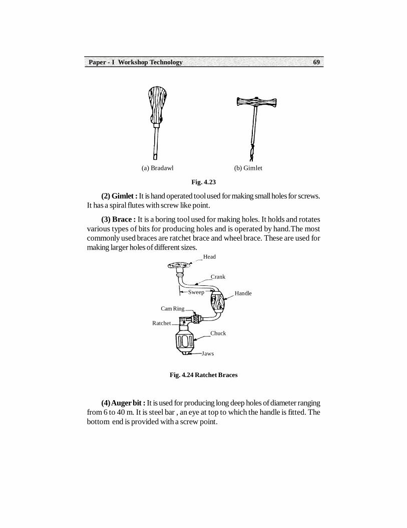
(a) Bradawl (b) Gimlet
Fig. 4.23
(2) Gimlet : It is hand operated tool used for making small holes for screws.It has a spiral flutes with screw like point.
(3) Brace : It is a boring tool used for making holes. It holds and rotatesvarious types of bits for producing holes and is operated by hand.The mostcommonly used braces are ratchet brace and wheel brace. These are used formaking larger holes of different sizes.
Fig. 4.24 Ratchet Braces
(4) Auger bit : It is used for producing long deep holes of diameter rangingfrom 6 to 40 m. It is steel bar , an eye at top to which the handle is fitted. Thebottom end is provided with a screw point.
Head
Crank
Handle
Chuck
Jaws
Ratchet
Cam Ring
Sweep
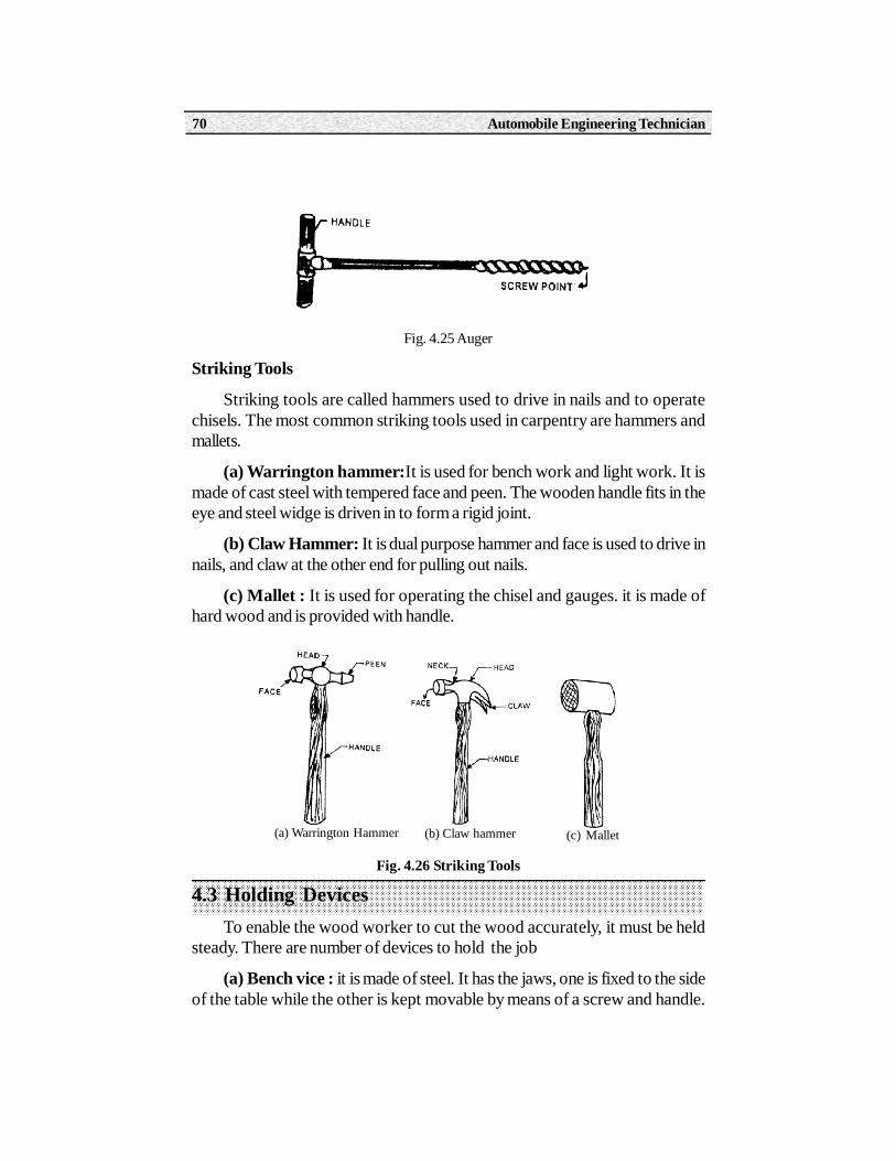
Fig. 4.25 Auger
Striking Tools
Striking tools are called hammers used to drive in nails and to operatechisels. The most common striking tools used in carpentry are hammers andmallets.
(a) Warrington hammer:It is used for bench work and light work. It ismade of cast steel with tempered face and peen. The wooden handle fits in theeye and steel widge is driven in to form a rigid joint.
(b) Claw Hammer: It is dual purpose hammer and face is used to drive innails, and claw at the other end for pulling out nails.
(c) Mallet : It is used for operating the chisel and gauges. it is made ofhard wood and is provided with handle.
Fig. 4.26 Striking Tools
4.3 Holding DevicesTo enable the wood worker to cut the wood accurately, it must be held
steady. There are number of devices to hold the job
(a) Bench vice : it is made of steel. It has the jaws, one is fixed to the sideof the table while the other is kept movable by means of a screw and handle.
(a) Warrington Hammer (b) Claw hammer (c) Mallet
Automobile Engineering Technician70

The job tab is held between the two jaws. The faces of jaws are lined with hardwood to prevent damage of work surface.
Fig. 4.27 Bench Vice
(b) Bench Stop : It is simply a block of wood projecting above the topsurface of the bench. This is used to prevent the wood from moving forwardwhen being planed.
(c) Bench hold Fast : It consists of a cast iron pillar, steel arm and screwwith a handle. It is used for securing the work to the bench. The pillar drops intoa hole bored in the bench and the screw operates the arm to hold work on thetable.
(d) Bench hook : It is used to support work while planning or cutting. It ismade of wood and can be placed conveniently on the work table.
(e) Sash Cramp : This is used for holding wide work such as frames ortops. It consists of a steel bar fitted with two jaws one of which is movable by ascrew and other is fixed into one of the spaced holes by a fastening pin.
Fig. 4.28 Bench Hook Fig. 4.29 Bench Holdfast
Paper - I Workshop Technology 71

Fig. 4.30 Sash Cramp
(g) G-Clamp : It is used to hold small works and it consists of frame witha fixed jaw at one end and movable jaw is operated by a screw and a thumb nutat the other end. It is also used to hold small parts for gluing.
Fig. 4.31 G-Clamp
4.4 Miscellaneous Tools(1) Rasp or File : It is used for finishing the wood surface. It has sharp
cutting teeth and it is used for finishing small curved surfaces.
Fig. 4.32 Rasp and File
(2) Scraper : It has a fine edge which cuts fine shavings and removes planemarks.
(3) Glass paper : Where a surface is having very small imperfections thatthe no other cutting tool will do, then glass paper is used. It consists of smallparticles of glass struck tosheet of paper. Its sharp edges cuts the wood.
(4) Ratchet Screw Driver : It is very useful for turning screws through afew degrees in.
(a) Rasp (b) File
Automobile Engineering Technician72

Fig. 4.42 Types of Screw Driver
(5) Screw Driver : These are used for screwing or unscrewing for thescrews used in wood work.
4.5 Carpentary Processes1. Marking : It is one of the most important operation of wood work and
the success of completing a job depends on accurate and orderly marking.These dimensions can be measured from an existing model and can be set outfrom the drawing prepared for the purpose. The dimensions are marked withrespect to the finished edge or finished face of a work.
2. Sawing : Sawing is one of the basic cutting operation carried out in acarpentry shop. To start the cut, the thumb of left hand is placed against theblade. This steadies the blade and enabling it to start in the right place. One ortwo short movements are given first, taking care that the saw works in the rightdirection. And then full, easy strokes are applied to cut the wood in a forwarddirection only. A point to note in all sawing work that the cut is made on one sideof the line already marked and that is on waste side
Fig. 4.33 Sawing
3. Planing : It is the operation of tuning up a piece of wood by a planner.The work for planning is supported by the bench stop in the vice. The pressureis applied during forward stroke and released on the returned stroke. It isimportant to move plane in straight line to avoid rounding at the ends and to
(a) Cabinet Screw Driver
(b) Ratchet Screw Driver
Paper - I Workshop Technology 73

obtain smooth surface. Planing is done along the grains. The surface planed aretested for flatness in all directions using a try square.
Fig. 4.34 Planning
4. Chiselling : It is the process of cutting excess wood with chisel to obtaindesired shape. In chiselling hard pressure is applied to remove thin layers. Malletis used when cuts are made across the grains.
Fig. 4.35 Chiselling
5. Boring : It is the process of making holes in wood. The work is securedto suitable vice and the hole position is marked with punch. The hole is providedby turning and feeding the bit into work.
6. Rebating : It is the process of cutting a recess along the edge of woodby a rebate plane. While rebating, the plane must be kept pressed into the sideof the wood.
7. Polishing : It is the process of producing a smooth reflecting surfacewith only the minimum removal of material. To obtain such a finish it is necessaryto incorporate a suitable abrasive within the polishing composition.
4.6 Carpentary JointsTerms joinery involves connecting of different wooden parts together by
means of properly made joints. In order to achieve good results, the joint made
(a) Surface Planning (b) Edge Planning
(a) Horizontal Paring (b) Vertical Paring
Automobile Engineering Technician74

in wood work are usually secured firmly by means of suitable fastners such asglues, dwels, screws, bolts and buts etc.
1. Halving Joint : The purpose of this joint is to reuse the corners andinter sections of the framing and at the same time keep all the face flush that inthe same plane. These joints are used in construction of frames. Marking andcutting of any joint must be accurate, so that it can shed together with the finalextreme surface level.
Fig. 4.36 ‘T’ Halving Joint
2. Mortise and Tenon Joint : It is strongest joint and is used for theconstruction of doors windows and frames. The tenon (tongue) fits into a mortise(mouth).
3. Mitre Joint : It is formed by cutting the ends at an angle. The two endsare joined by nails or screws. This joint is used in photo frames.
Fig. 4.37 Mortise & Tenon Joint
4. Dovetail Joint :This is strongest joint used for construction of boxesand cup boards.
(a)DovetailHalving joint (b)T- Joint
Paper - I Workshop Technology 75

Fig. 4.38 Mitre Joint Fig. 4.39 Dovetail Joint
5. Butt Joint : The fastening of boards edges to edges is frequentlynecessary to give a wider board. eg. Drawing board. In butt joint two trueedges are joined with glue. If it is properly done this joint is very strong.
Fig. 4.40 Butt Joint
4.7 Wood Working MachinesWood working machine plays a vital role in the modern wood work
particularly where large scale production of wooden articles is carried out.Modern development in wood working machinery with regard to the greatersafety for the operator, easy operation and greater accuracy. These developmentsled to higher output.
The commonly used wood working machines are as follows.
1. Wood Turning Lathe : It is one of the important and oldest machineused in carpentry shop. This is employed primarily for turning jobs in makingcylindrical parts. It resembles the engine lathe most frequently used in the machineshop and consists of a cast iron bed, head stock, tail stock, tool rest, live anddead centres and speed control device.
In practice the work piece is either clamped between two centres or on theface plate. Long jobs are held between the centres and turned with the help of
Automobile Engineering Technician76

goauge, chisel, parting tools. Generally the lathe is supplied together with a numberof accessories for making it useful for a variety of jobs.
Fig. 4.41 Wood Turning Lathe
2. Circular Saw : It can be used for ripping, cross cutting, bevelling andgrooving. This saw has flat table upon a which the work rests while being cut, acircular cutting blade, cut-off guide and a ripping fence that acts as a guide whilesawing along the grain of the wood. The circular saw usually has provisions fortilting the table upto 45o to enable the machine to cut at different angles requiredduring mitering and levelling.
Fig. 4.42 Circular Saw and Its Use
3. Band Saw : It means that an endless metal saw band that travels overthe rims of two or more rotating wheels. Other parts of band saw are frame,table ,saw guide, saw tensioning arrangement. It is most useful for making curvedor irregular cuts in wood. The band saw is available in two models vertical andhorizontal. In horizontal band saw, two wheels are arranged side by side and thetable is mounted underneath. In the vertical band saw the wheels are arrangedone over the above in a vertical plane below the table, angular cuts are obtainedby tilting the saw table.
Paper - I Workshop Technology 77
Fig. 4.43 Band Saw
4. Wood Planner : It is used for planning large work pieces and capableof producing true surface with enough accuracy at a faster rate. It consist oftable over which the work is fed against a revolving cylindrical cutter head carrying2-3 knifes. The cutter is mounted on a over head raft and the table can raised orlowered to attain desired thickness.
Fig. 4.44 Principle of Wood Planer
5. Sanding Machine : The sanding machine are used for producing smoothsurface after planning the wood. It seems a surface suitable for painting. Theaction of sanding machine is some as the sand paper producing the smooth
Automobile Engineering Technician78

surface. In sanding an abrasive is rubbed over the surface of wood to weardown hills by friction and thus present a smooth, uniform surface.
Fig. 4.55 Belt Sander Fig. 4.56
Summary1. Carpentry is the processing of wood to obtain desired shape and size
2. In carpentry hand tools are classified in to five types ie marking tools ,cutting tools ,boring tools ,striking tools and holding devices.
3. The wood working operations includes marking, sawing, planing,chiseling, boring and rebating.
4. The successful construction of wood depends on satisfactory joining.Themost common carpentry joints are halving joint,mortise joint tenonjoint,mitre joint,dovetail joint,and butt joint.
5. Wood working machines are primarily intended to increase theproductivity with higher accuracy which includes wood turning lathe,bandsaw,circular saw, sanding machine.
Activity 1. A learner should collect T-halving joint.
2. A learner should collect plain tenon joint.
3. A learner should collect dovetailbridge and bridge cornerjoint.
Short Answer Type Questions
1. Name different cutting tools used in carpentry.
2. What is the use of pincer.
3. Name different types of planes.
Work Piece
Table
Belt
Stop
Guard
Wheel
Tool or workres
Paper - I Workshop Technology 79

4. Listout carpentry joints.
Long Answer Type Questions1. Explain about any four carpentry processes.
2. Explain about wood turning lathe with neat sketch.
OJT Questions1. Make saw practicing.
2. Make Plane practicing.
3. Make boring practice.
4. Prepare a corner , T , butt joints etc., from a given wooden piece.
Automobile Engineering Technician80

Learning ObjectivesOn completion of this unit, a learner will be able to
• Know different types of hand tools, and their usage.
• Describe important smithy operations.
• Explain various machine forging operations.
• Know the safety precautions to be followed while doing welding.
• Get the knowledge about arc welding and gas welding procedure andproper handling of equipment used for the purpose
5.0 IntroductionForging is the process of deforming the metal into different shapes by heating
up to plastic state and by hammering or pressing at red hot condition. The processis usually carried out above re-crystalization temperature. Therefore this processis called hot working process. The term usually preferred to the production ofheavy parts and in large scale.
5.1 Hand Tools used in Forging
The following hand tools are used in forging.
Forging and Welding
5UNIT

Automobile Engineering Technician82
1) Anvil 2) Swage block 3) Tongs
4) Hammer 5) Chisel 6) Hardie Tools
7) Swages 8) Fullers 9) Flatters
10) Set Hammers 11) Punches 12) Drifts
1. Anvil : The anvil forms a good support for black smith’s work whenhammering. Its body is made of mild steel. These are made in different forms toprovide the means for other forging operations. The usual form of anvil has around hole called pitchel hole for bending rods and a square hole called hardiehole for holding square shanks of various tools such as swages, fullers, hardies,chisels.
Fig. 5.1 Anvil
2) Swage Block : It has different sizes and shapes of slots like half round,square and rectangular along its four sides. It is made of cast iron. This is usedas a support in punching holes and forming different shapes.
Fig. 5.2 Swage Block
Round HoleHardie Hole
StepWorking Face
Cutting FaceHorn
BeakBody
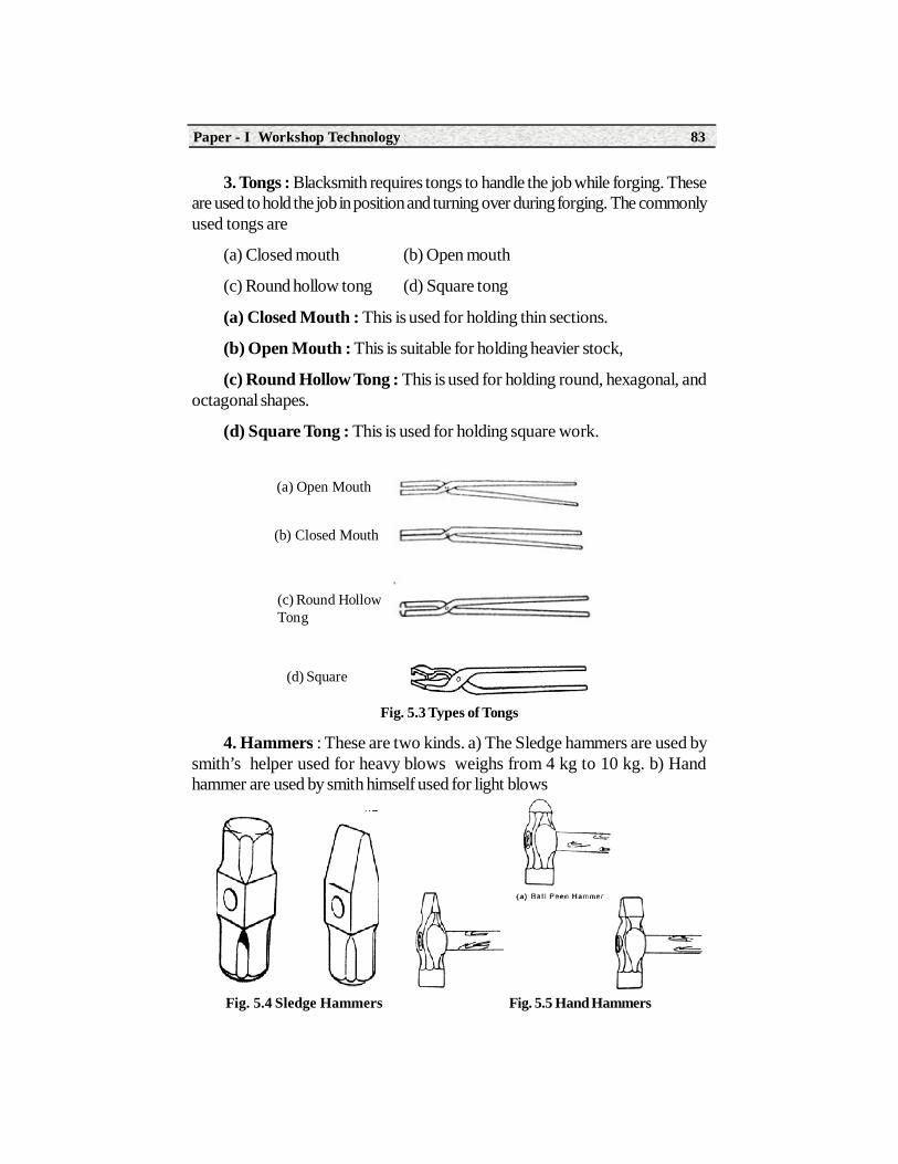
Paper - I Workshop Technology 83
3. Tongs : Blacksmith requires tongs to handle the job while forging. Theseare used to hold the job in position and turning over during forging. The commonlyused tongs are
(a) Closed mouth (b) Open mouth
(c) Round hollow tong (d) Square tong
(a) Closed Mouth : This is used for holding thin sections.
(b) Open Mouth : This is suitable for holding heavier stock,
(c) Round Hollow Tong : This is used for holding round, hexagonal, andoctagonal shapes.
(d) Square Tong : This is used for holding square work.
Fig. 5.3 Types of Tongs
4. Hammers : These are two kinds. a) The Sledge hammers are used bysmith’s helper used for heavy blows weighs from 4 kg to 10 kg. b) Handhammer are used by smith himself used for light blows
Fig. 5.4 Sledge Hammers Fig. 5.5 Hand Hammers
(a) Open Mouth
(b) Closed Mouth
(c) Round HollowTong
(d) Square

Automobile Engineering Technician84
5. Chisels : These are used for cutting metals and for necking prior tobreaking. They may be hot or cold depending on whether the metal to be cut ishot or cold. The hot chisel is used for cutting the metal when hot and its edge isat an angle of 30o. The cold chisel is used to cut cold materials.
(a) Hot Chisel (b) Cold Chisel
Fig. 5.6 Types of Chisels
6. Hardie Tools : It is a cutting tool with square shank to fit in the squarehole of the anvil. It is used in combination with hot or cold chisel.
Fig. 5.7 Hardie Tools
7. Swages : Swages are used for reducing and finishing the round, square,and hexagonal shapes. A set of swages are designed for round shapes andsquare shapes
Fig. 5.8 Swages

Paper - I Workshop Technology 85
8. Fullers : These are used in pair for necking down a piece of work. Thebottom fuller has square shank to fit in the hardie hole and top one is providedwith handle.
Fig. 5.9 Fullers and Their Use
9. Flatters : These are used to obtain smooth and finished flat surfaceswhich have already been shaped by fullers and swages.
Fig. 5.10 Flatter
10. Set Hammers : It is really a form of flatter. A set hammer is used forfinishing corners in shouldered work where the flatter would be inconvenient touse
Fig. 5.11 Set Hammer and Its Use
11. Punches : A punch is used for making holes in metal parts when it is atforging heat.

Automobile Engineering Technician86
Fig. 5.12 Punch and Its use
12. Drifts : It is a tool for enlarging the hole made by punch. They aredriven right through the punched hole.
Fig. 5.13 Use of Drift
5.2 Heating DevicesThe stocks are heated to the correct forging temperature in a smith’s hearth
or in a furnace. Gas oil of electric resistance furnaces are induction heatingclassified as open or closed hearths. Gas and oil are economical, easily controlledand mostly used as fuels. A common form of smith;s hearth is made of thick steelsheets. It is lined with fire bricks. It holds the coke and provides with tuyere anda tank containing water. Air is supplied through a fan or blower to hearth. Theair is admitted into the hearth may be regulated by a suitable valve arrangement.The hood at the top collects the fumes from the fire. Smoke and gas are finallyremoved into atmosphere. After firing the hearth the work piece is kept underthe fire. When it becomes sufficiently hot it is removed from the hearth forshaping.

Paper - I Workshop Technology 87
5.3 Smithy OperationsFor giving desired shape to the metal, number of operations are performred
in a smithy shop.They are listed here under.
a) Upsetting b) Drawing down
c) Setting down d) Bending
e) Fullering f) Swaging
g) Flattering
a. Upsetting : It is the process of increasing cross-sectional area at theexpense of its length. It is achieved by heating the bar at the middle and strikingthe end with hammer as shown in diagram.
Fig. 5.14 Upsetting
b. Drawing Down : It is the process of decreasing the cross section areawith a corresponding increase in length of a bar. The operation is carried byusing the edge or horn of the anvil or fullers. The bar is finally finished by flatters.
Fig. 5.15 Drawing Down
(a) Edge and Straight Peen Hammer(b) Set of
(c) Horn and Hand (d) Finishing by Flatters

Automobile Engineering Technician88
c. Setting Down : It is the process of decreasing thickness rather thangeneral reduction of area. It is initiated with fullers and finished with flatters.
Fig. 5.16 Setting down
d. Bending : This can be performed to produce different types of bentshapes such as angles, ovals and circles etc. for making a bend at that particularpart of job.
Fig. 5.17 Bending
e. Fullering : It is the process of increasing the length by necking the barbetween two fullers.
f. Swaging : It is an operation through which desired shapes are obtainedon the job by placing it an similar shape slot on the swage bock and thenapplying top swage on the other side of the job.
g. Flattering : It is an operation through which the surface of job shapedby fulters and swages are usually finished.
Blow BlowBlow
FullerFlatter
Set Hammer
a. Bending of Horn b. Angular bending in a vice c. Bending in a fixture for mass production

Paper - I Workshop Technology 89
Fig. 5.18 Swaging
5.4 Machine ForgingHeavy and medium forging are made in machine forging where as in hand
forging only a limited quantities of light forgings are produced. In machine forgingsledge hammer is replaced by power driven forging hammers or presses. Becausesledge hammers are unable to produce required degree of deformation of metalduring forging.
5.5 Forging Hammers
The forge hammers are classified as
(1) Mechanical
(2) Drop Hammers
(1) Mechanical Hammers are classified as
Mechanical hammers are classified as
a) Spring hammer
b) Pneumatic Hammer
(a) Spring Hammer : It is a light weight power hammer and is adopted forsmall forgings. It has a heavy rigid frame carrying a vertical projection at its top.This projection acts as housing for the bearing in which the laminated springoscillates. The rear end of this spring is pinned to small end of connecting rodand its front end is connected to a vertical top to which the die is fixed. Thebottom end of the connecting rod is attached to an eccentric sheave. This in turnconnected to the crank wheel that is driven by an electric motor. The bottom dieis keyed to the anvil block.
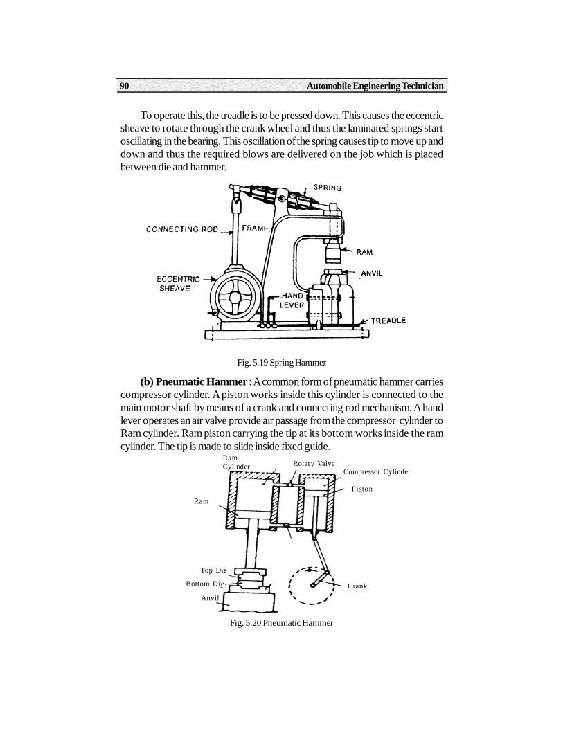
Automobile Engineering Technician90
To operate this, the treadle is to be pressed down. This causes the eccentricsheave to rotate through the crank wheel and thus the laminated springs startoscillating in the bearing. This oscillation of the spring causes tip to move up anddown and thus the required blows are delivered on the job which is placedbetween die and hammer.
Fig. 5.19 Spring Hammer
(b) Pneumatic Hammer : A common form of pneumatic hammer carriescompressor cylinder. A piston works inside this cylinder is connected to themain motor shaft by means of a crank and connecting rod mechanism. A handlever operates an air valve provide air passage from the compressor cylinder toRam cylinder. Ram piston carrying the tip at its bottom works inside the ramcylinder. The tip is made to slide inside fixed guide.
Ram
Top Die
Bottom Die
Anvil
RamCylinder Rotary Valve
Compressor Cylinder
Piston
Crank
Fig. 5.20 Pneumatic Hammer

Paper - I Workshop Technology 91
Air is compressed on both upward and downward strokes of the piston incompressor cylinder. This air enters into the ram cylinder through a control value.
Hammer falls by imparting blow to work piece due to its own weight whenthe air pressure exerted above the piston. The upward stroke of the hammer isobtained by exhausting the air above the piston and admitting in beneath thepiston.
(2) Drop Hammer
The drop hammer is suitable for production of large number of identicalforging components also. High quality components are by made this process.There are two types a) Steam or Air drop hammer b) Board Drop or Gravitydrop hammer
(a) Steam or Air Drop Hammer : These hammers are run by steam orcompressed air. These are similar to pneumatic hammer except that they do nothave a built in compressor. The generation of compressed air or steam takesplace separately and not within the hammer. There are two types of steamhammers in common use i) Single acting and ii) Double acting
In single acting steam (or air) hammer, the steam (or air) is admitted throughbottom part which lifts the ram upwards and then the ram is allowed to fall downunder gravity to provide required blow.
Fig. 5.21 Steam Hammer
(b) Board Drop (Gravity drop Hammer) : In this case the energy blowis entirely depends upon the weight of the hammer. The ram is attached to the
Safety Cover
Cylinder
Frame
Ram
Dies
Anvil
Valves
Controls

Automobile Engineering Technician92
board which passes between two rockers which are in continuous motion. Theram moves up with the help of routers and is held at desired height by clampsuntil they are released by the operator. At a preset height the board is rebasedso that it strikes the die which is fixed to the anvil. The work is deformed by theforce of blow. If the weight of the ram and the height from which it falls isgreater, the impact of blow will be more.
Fig. 5.22 Board drop Hammer
5.6 FORGING PRESSES
In press forging, the metal is shaped by squeezing it into the die cavities bypressing. Presses of 500 to 6000 tonnes capacities are in common use. Normallytwo types of presses are used a) Hydraulic presses are used for heavywork b)Mechanical presses are used for light work.
Mechanical presses operate at faster speed than hydraulic presses, buthydraulic presses provide greater squeezing force than mechanical presses.
WeldingIntroduction
Welding is the process of joining two or more metals by application of heatwith or without application of pressure and addition of filler rod. Now the basicpurpose of welding is to provide a means to join pieces by raising their temperatureto the fusion point so that they forms a pool of molten metal at the ends to bejoined and if needed supplement their pool with a filler metal which is normallysame metal as the metal pieces to be joined.
Paper - I Workshop Technology 93
Types of Welding
The modern methods of welding may be classified under two broad headings.a) Plastic welding b) Fusion Welding
In plastic welding or pressure welding, the pieces of metal to be joined areheated to a plastic state and then forced together by external pressure.eg forging
In fusion welding or non pressure welding, the material at the joint is heatedto a molten state and allowed to solidify. eg.Gas welding and arc welding etc.
1. Gas Welding : It is a fusion welding or non pressure welding method inwhich a strong gas flame is used to raise the temperature of the ends of thepieces to be joined to a heat sufficient to melt them. The metal thus melted startsflowing along the ends to be joined and forms a strong weld joint after solidifies.So many different combination of gases may be used, but the most common ofthese are oxygen and Acetylene, O2 & H2. Oxygen and hydrogen gas welding isused for metal for low melting point like non ferrous metal.
5.6.1 Oxygen - Acetylene WeldingThis welding can be used for welding almost all metals and alloys used in
engineering practice. The highest temperature that can be produced by a flameof oxygen and acetylene is nearly 3200OC. The correct adjustment of the flameis important for reliable works. When oxygen and acetylene are supplied totorch in nearly equal volumes, a neutral frame is produced having a maximumtemperature of 3200oC.
This neutral flame is widely used for welding steel, Stainless steel, Castiron, copper, Aluminium etc. An oxydising flame in which there is an excess ofoxygen used for welding brass. A carburising flame is one in which there is anexcess of acetylene compared to oxygen used for welding cast iron
Gas Welding Equipment
The most commonly used tools and equipment for oxy acetylene weldingconsists of following.
a) Welding torch b) Pressure Regulator
c) Welding tip d) Hose and Hose fittings
e) Goggles, gloves and spark lighter f) Gas cylinders
a) Welding Torch : This is a tool for mixing oxygen and acetylene inrequired proportions and burning the mixture at the end of its tip.

Automobile Engineering Technician94
(b) Welding Tip : It is that portion of the welding apparatus through whichthe gases pass just prior to their ignition and burning. These tips of differentshapes and sizes are governed by the diamter of opening. The diameter of thetip opening used depends upon the types of metal to be welded.
(c) Pressure Regulator : The function of a pressure regulator is to reducethe cylinder pressure to required working pressure and also to produce a steadyflow of gas regardless of the pressure variation at the source.
(d) Hose and Hose Fittings : The hose for welding torches should bestrong, durable, nonporous and light. The most common method of piping bothoxygen and acetylene gas is the reinforced rubber hose. The colour of oxygenpipes is black and acetylene is red.
(e) Goggles, Gloves and Spark Lighter : Goggles are fitted with colouredlenses are provided to protect the eyes from harmful heat , ultraviolet and infraredrays.
Gloves : These are used to protect the hands from any burnings or injury.
Spark Lighter : Provides a convenient and instant means for lighting thewelding torch.
Gas Cylinders : Oxygen cylinders are usually charged with about 40 litresof oxygen at a pressure of 154 kgs/ cm2 at 21oC. A full cylinder has a weight ofabout 80 kgs. Oxygen cylinder is painted with black. A safety valve is providedto release the oxygen before there is any danger of excess pressure.
Acetylene Cylinder : These cylinder carry a porous mass inside soakedin acetone which has a capacity to dissolve 25 times its own volume of acetylenefor every atmosphere of pressure applied. These cylinders are usually filled to apressure of 16 kgs to 21 kg/ cm2. It is painted with maroon colour
Gas Welding Procedure :
1. Arrange the two cylinders (O2 & C2 H2) in proper position (upright).
2. Blow out both cylinder valves before fitting the regulators so that all dirtmay be cleaned out and this operation should be done quickly.
3. The regulator and valve fitting should be thoroughly checked that there isno oil or grease.
4. Fix the oxygen and acetylene regulator and pressure gauges to cylinders.
5. Connect or check hose fittings of O2 and C2 H2.
Paper - I Workshop Technology 95
6. Open the cylinder valves gradually to avoid abrupt strain.
7. Check out for leakages at all joints before starting the work.
8. To start the work turn on the acetylene first and allow it to pass throughthe nozzle. Then turn on the oxygen slightly and allow the mixture to flow throughhoses and blow pipes are full and cleared off air.
9. Adjust the required pressure of the two gases and light the mixture.
10. Adjust the flames by regulating the supply of the gasses in correctproportions.
11. After the work is completed the oxygen valve should be closed firstfollowed by the acetylene valve.
12. Care should be taken always that oil and grease do not present at anyfittings may lead to an explosion.
5.6.2 Arc WeldingArc welding is the most extensively employed method of joining metal parts.
Here the source of heat is an electric arc. It is a fusion welding process in whichno mechanical pressure is applied for joining the metal. In this, the metal piecesto be joined are heated locally to the melting temperature by creating an electricarc and then allowed to solidify to form the welded joint.
Arc Welding Equipment
1. AC or DC welding machine 2. Electrode 3. Electrode holder
4. Cable, Cable connectors 5. Cable lugs. 6. Chipping hammer
7. Earth Clamps 8. Wire brush 9. Helmet
10. Safety goggles 11. Hand gloves 12. Appron and sleeves.
1. Welding Machine : Both AC and D.C’s are used for arc welding.When welding is employed the current is generated by a D.C generator. Thisgenerator can be driven by means of an electric motor or by means of petrol ordiesel engine. With the result D.C arc welding processes can be employedirrespective of whether main A.C supply is available or not.
For A.C arc welding a step down transformer is used which receives currentfrom the supply mains at 200-440 volts and transforms it to the required voltagefor welding i.e 40-100 volts. Arc welding machine consists of a steel tank mountedon three tyred wheels and the front wheel is steerable by means of a draw bar.An oil cooled, double wound step down transformer reduces the supply mains

Automobile Engineering Technician96
voltage to a welding voltage of 80 volts. All windings are totally enclosed in thesteel tank. The output of transformer can be varied by rotating a hand wheelwhich alters the air gap in the core of the choke resulting in stepless regulation ofthe current between 50-400 amps. The welding setting can be directly read atthe window on the top cover.
(2) Electrode : Both non consumable and consumable electrodes are usedfor arc welding. Non consumable electrode, may be made of carbon, graphiteor tungsten which donot consume during the welding operation. Consumableelectrode may be made of various metals depending upon their purpose and thechemical composition of the metal to be welded. These consumable electrodesmay be bare or coated. Bare electrodes are cheaper but the weld producedthrough these are poor quality and it needs high degree of skill on part of welder,if satisfactory results are expected. Therefore bare electrodes are rarely used inmodern welding practice, where as more popularly used in metal arc weldingare the coated electrodes which carry a core of bare metallic wire, providedwith a coating on the outside surface. Main advantage in using coating electrodeis to protect the molten metal from the oxidisation and nitrogen , to theestablishment and maintenance of the arc. Mild steel is the most commonlyused material for the core wire. Some of the other metals and alloy are also usedas core wire material. The electrode covering the flux coating perform manyfunctions that reducing atmosphere to prevent oxidation, forming stage with metalimpurities, establishing arc, providing necessary alloying elements to the weldmetal. The common ingredients of a flux are asbestos, mica, silica, flour spar,stealite, mg carbonate etc.
Arc Welding Procedure
Before starting the welding, the joint should be prepared well and thoroughlycleared to remove dirt, grease, oil, oxide etc. from the work surface. Edges ofthickened section should be bevelled . The work pieces should be firmly held.Make sure that connection are given properly to main supply as well as electroderod and work piece to be welded. The arc column is generated between anodewhich is positive pole of power supply and the cathode (-ve pole). When thesetwo conductors of an electric circuit are brought together and separated for asmall distance i.e. 2-4 mm such that an electric arc is formed. Heat is generatedas the ions strike the cathode. The temperature of an electric arc, depends uponthe type of electrode between which it struck. The heat of the arc raises thetemperature of the parent metal which is melted forming a pool of molten metal.The electrode rod is also melted and transferred between metal pieces to bewelded.Two thirds of heat is generated near the positive pole and one third isdeveloped near the negative pole. As a result an electrode that is connected to

Paper - I Workshop Technology 97
the positive pole will burn away approximately 50% faster than when connectedto the negative pole. The electrode of suitable size should be held at an angle of60-80o with work piece. Then the welding may be proceeded by maintaining agap 2-4 mm between the electrodes. After desired length has been welded theelectrode holder should be lifted quickly to break the arc.
Summary1. Forging of a heated metal by hammering or pressing.
2. Different tools used in forging are classified as
a) Heating Devices
b) Supporting tools
c) Holding tools
d) Cutting Tools etc.
3. Most of the forging work is done with hot metal and heating of metal iscarried out in a hearth or furnace are two types a) Open hearth
b) Closed hearth.
4. Supporting tools are used to support the work while hammering.
5. Most important forging operations are upsetting, drawingdown, setting down, bending, fullering, swaging and flattering.
6. Machine forging is suitable to produce large number of identical forgingsand is carried out by forcing the metal into die cavities by repeatedhammer blows.
Activity1. A learner should collect a round bar made from square rod.
2. A learner should collect S-hook
3. Collect a crane hook
4. Collect T-bolts
5. Collect arc welded, T-Joint, Lap joint, Butt joint.
6. Collect gas welded, T-joint, lap joint, and butt joint.

Automobile Engineering Technician98
Short Answer Type Questions1. Define forging.
2. What is meant by upsetting ?
3. What are Tongs ?
4. Write about supporting device in forging
Long Answer Type Questions1. Explain about any four smithy operations ?
2. Name different types of machine forging hammers and explain about anyone them
OJT Questions1. Make the practice of usage of forging tools.
2. Prepare a round bar from a square bar.
3. Make a crane hook, S-hook.
4. Make a butt joint by arc welding process.
5. Make a lap joint by Gas welding process.

Learning ObjectivesOn completion of this unit a learner will be able to
• Describe various hand moulding tools used in foundry.
• Explain about pattern making and different type of patterns used
• Classify moulding sands and their properties.
• Know the purpose of core and core making.
• Explain about various casting methods.
• Know about various defects in casting.
IntroductionManufacturing is the art of transforming the raw material into finished
product. This chapter deals with manufacture of products from molten metaland the products obtained are called Casting. Casting are produced when themolten metal is poured into the mould cavity and left to solidify. This is cheapestmethod of producing parts to a given shape.
Foundry
6UNIT

Automobile Engineering Technician100
6.1 Advantages and Linitation of CastingAdvantages of Casting
1. Size is not a limitation
2. There are several metals which can be cast.
3. Intricate components with cavities can be casted with accuracy andgood surface finish.
4. Casting, in general resists creep under high temperature.
5. Metal casting can be adopted for job work as well as for mass production.
Disadvantages
1. The process is not suitable for the metals having high melting point andlow fluidity.
2. Casting do not exhibit directionality of properties . The strength andtoughness of castings are usually inferior to forgings.
6.2 Foundry Equipment and Hand Mould ToolsFoundry tools and equipment may be classified into three groups namely
hand tools, flasks and mechanical tools.
Hand Tools in Moulding
(1) Shovel : It is used for mixing and tempering the moulding sand andloading the sand into flask.
Fig. 6.1 Shovel
(2) Riddle : It is a wire mesh fitted in to a wooden frame used for screeningthe sand and to scatter the fine moulding sand over pattern.

Paper - I Workshop Technology 101
Fig. 6.2 Riddle
(3) Rammer : These are used for packing the sand around the pattern in aflask. This is made of hard wood with one end flat and other wedge.
Fig. 6.3 Rammer
(4) Trowels : These are used for cleaning, smoothing and patching the flatsurface of the mould.
Fig. 6.4 Types of Trowels
(5) Slick : It has a flat on one end and spoon on the other end. It is used forpatching and smoothing the mould after the pattern has been drawn.
Fig. 6.5 Slick
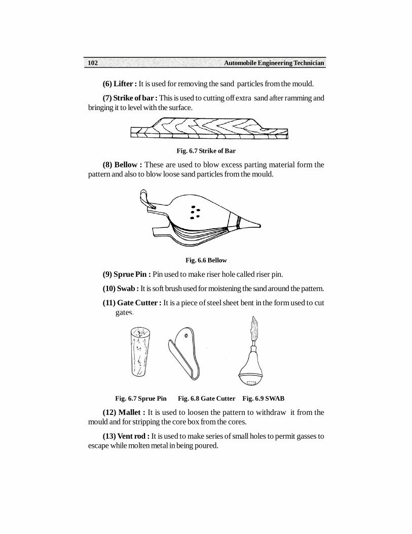
Automobile Engineering Technician102
(6) Lifter : It is used for removing the sand particles from the mould.
(7) Strike of bar : This is used to cutting off extra sand after ramming andbringing it to level with the surface.
Fig. 6.7 Strike of Bar
(8) Bellow : These are used to blow excess parting material form thepattern and also to blow loose sand particles from the mould.
Fig. 6.6 Bellow
(9) Sprue Pin : Pin used to make riser hole called riser pin.
(10) Swab : It is soft brush used for moistening the sand around the pattern.
(11) Gate Cutter : It is a piece of steel sheet bent in the form used to cut gates.
Fig. 6.7 Sprue Pin Fig. 6.8 Gate Cutter Fig. 6.9 SWAB
(12) Mallet : It is used to loosen the pattern to withdraw it from themould and for stripping the core box from the cores.
(13) Vent rod : It is used to make series of small holes to permit gasses toescape while molten metal in being poured.

Paper - I Workshop Technology 103
Fig. 6.10 Vent Rods
(14) Draw Spike or Screen : It is used to rap and draw patterns from thesand.
(15) Water Sprinkle : It is a device used for wetting and tempering themould sand.
Fig. 6.11 Water Sprinkle
(16) Spirit Level : It is used for aligning flasks and adjusting the straightedges in pit moulding.
Moulding Boxes : Sand moulds are prepared in specially constructedboxes called flasks. The purpose of flask is to impart the necessary strength tothe sand in moulding. Moulding flask is generally made into two parts. TheCope (Top section) and the drag (bottom section). These two are held in positionby dwel pins. The common types of moulding boxes are
Fig. 6.12 Moulding Boxes
(a) Snap flask : It is a small flask with open form. It is made with hinge onone corner and a lock on the opposite corner. It can be removed from themould before it is poured.
Automobile Engineering Technician104
(b) Box Flask : It is suitable for small and medium size castings, it is removedfrom the mould only after solidification of casting.
(c) Wooden moulding boxes : Wooden boxes are often used for makingrelatively large castings.
Mechanical Tools: These tools in the foundry include the many types ofmoulding machines that will ram the mould, roll it over, and draw the pattern.Besides there are power operated riddles sand mixtures and sand conveyersetc.
6.2 Types of Sands and PropertiesThe common sources of collecting foundry sands are from rivers, lakes,
sea and deserts. The principal ingredients of moulding sands are silica sandgrains, clay, moisture and miscellaneous materials. Moulding sand is classifiedas under
(1) Natural sand
(2) Synthetic sand
Natural Sand : Natural sand containing required proportion of clay (5-20%) is referred as green sand. It requires only to mix water. The clay developsthe strengths and plasticity for moulding. They are less refractory than syntheticsand.
Synthetic: These are obtained by crushing and mixing soft yellow sandstone, carbon ferrous rocks. This sand essentially high silica grains containingno clay in natural form. They are mixed with clay (3-5%) and water 3-4% todevelop required moulding properties.
Properties of Moulding Sand
Proper moulding sand must posses six important properties.
(1) Porosity : The sand should have sufficiently porous to provide a passagefor steam and gases other wise the gases penetrate into metal which leads to theformation of gas cavities in casting.
(2) Plasticity : It is the ability of a sand to acquire shape from the patternthat is moulded and retain it during casting.
(3) Flowability : It is the ability to flow under externally applied forces in todeeper sections of pattern and uniformly fill the flask.

Paper - I Workshop Technology 105
(4) Collapsability : It is the property of sand that permits it to collapseeasily during its knockout from the casting.
(5) Adhesivness : It is the ability of sand to stick to the surfaces of mouldingboxes. This enables the mould to retain in a box during handling.
(6) Cohesiveness : It is the ability of sand particles to stick each other. Itrefers to the strength of moulding sand to hold the grains together.
(7) Refractiveness : It is the ability of sand to withstand the heat of moltenmetal without fusion.
6.3 Pattern : Classification and MakingThe type of pattern used depends upon the design of casting, complexity of
shape, the number of castings to be produced. The following types of patternsare in common use.
(1) Solid Piece
(2) Split pattern
(3) Match plate pattern
(4) Gated pattern
(5) Sweep pattern
(6) Cope and drag pattern etc.
(1) Solid Pattern : It is made in single piece and is best suited for limitedproduction.
Fig. 6.13 Solid Pattern
(2) Split Pattern : It is used for intricate casting of unusual shapes. splitpattern may be two or three piece.

Automobile Engineering Technician106
(3) Match plate Pattern : These patterns are mostly used in machinemoulding as well as for producing large number of small castings by handmoulding.
(4) Gated Pattern : These patterns include gates and risers for producingcasting. The use of gated pattern eliminates the time required to cut the gatingsystem by hand.
(5) Sweep Pattern : The template made of wood or metal revolving arounda fixed axis in the mould shapes the sand to the desired contour. It is suitable forproduction of symmetrical castings.
Fig. 6.13 Sweep Pattern
Fig. 6.14 Gated Pattern
(6) Cope and Drag Pattern : This pattern is made of two halves whichare mounted on different plates. In this case, cope and drag parts of the mouldare made separately..

Paper - I Workshop Technology 107
Pattern MakingA pattern may be defined as a replica or facsimile model of the desired
casting which, when packed in a suitable moulding material, produces a cavitycalled mould. This cavity when filled with molten metal produces desired casting.
A pattern size is slightly larger than the finished casting by an amount calledallowance. 1) Shrinkages allowance : The pattern must be made over size tocompensate for contraction of liquid metal on cooling. 2) Machining allowance: It necessary to produce the finished surface of casting by machining. The excessin the dimensions of the casting over the finished casting called machiningallowoance. 3) Draft Allowance : When a pattern is removed from a mould, thetendency to tear away the edges of the mould is greatly reduced if the verticalsurfaces of the pattern are tapered inwards. 4) Distorsion Allowance : Thisallowance is applied to the castings of irregular shapes that are distorted incooling because of metal shrinkages. The material selected for a pattern shouldbe easily workable,durable and should maintain dimensional accuracy. Thecommon material used for making pattern are wood, metal, plastic and wax.
The pattern maker, before making pattern should study the blue print.Reproductions of the blue print laid out to full size scale on a flat smooth woodenboard. Select a working face and place a working edge straight, smooth andsquare with the face of the board. Start the layout of a symmetrical pattern fromcentre line. Select the proper contraction rule for making layout measurements.Mark straight line with knife edge and circles with divider. colour the layoutmarks and preserve the layout until the pattern has been constructed.
After preparing the layout proceed for pattern construction. Study the layoutand decide the location of parting lines. As per the layout, try to visualize theshape of the pattern and determine the number of separate pieces to be made.Start the construction of pattern from main part of its body. Cut and shapedifferent parts providing adequate draft on them. Check all the prepared partsfinally by placing them over the prepared layout. Assemble different parts inposition by glueing or by means of dowels pin. Finally check the whole of thecompleted pattern for accuracy.
6.4 Core and Core MakingCores are separate shapes of sand that are generally required to form the
hollow interior of the casting or a hole through the casting. These are placed inthe mould cavity before pouring to form the interior surface of the casting andare removed from finished part during shakeout and further processing.

Automobile Engineering Technician108
Core MakingCore making consists of the following operations 1) Core Sand
preparation 2) Core moulding 3) Baking 4) Core finishing
(1) Core Sand Preparation : The first consideration in making a core isto mix and prepare the sand properly. The mixing must be homogenous so thatthe core will be of uniform strength throught out.
(2) Core Moulding : Core is then made manually or with machines.Normally a core box is required for the preparation of cores.
(3) Core Baking : After the cores are prepared and placed on metal plateor core carriers, they are backed to remove the moisture and to develeop thestrength of the binder in core ovens at temperatures from 150oC - 400oCdepending upon the types of the binder used, the size of the cores and the lengthof baking time.
(4) Core Finishing : All rough places and unwanted fins are removed byfiling some cores are made in two or more pieces which must be assembledusually by pressing together with dextrin. The last operation in making of a coreis to apply a fine refractory coating to the surfacing.
6.5 Green Sand MouldingThese moulds are prepared with natural moulding sands or with mixture
of silica sand, bonding clay, and water. These materials are thoroughly mixed inproportions which will give desired properties for the class of work being done.The clay has been added to withstand the forces as the molten metal pouredinto the mould. These are widely used for small and medium castings. In thiscase no dry process of mould is necessary and the molten metal is poured assoon as mould is prepared. The term green refers to the moisture and not thecolour of the sand. To prevent the sand from burning on the face of the mould,a layer of facing sand is given to surrounding pattern.
6.5.1 Dry Sand MouldingThese sand moulds are prepared in similar way as in green sand moulds
except that the mould is dried before pouring molten metal. Drying is usuallycarried out in oven at about 240oC. The time of backing is depending on thebinders used in the sand mixture and the amount of mould surface to be dried.The removal moisture makes the mould stronger, improves erosion resistanceand surface condition. Dry sand moulds are used in preference to green sandmoulds for making medium to large size castings of cast iron and steel.

Paper - I Workshop Technology 109
6.6 SHELL MOULDING
It is basically a sand moulding in which the clay is replaced by resin bondingagent. it consists of the following steps.
(a) Preparation of thin shell made of a mixture of sand and thermo settingresin around a heated metal pattern.
(b) Separating the shell from the metal pattern
(c) Clamping two halves of the shell to form the mould.
(a) Preparation of Thin shell : Silica sand is thoroughly mixed withabout 5% thermo setting resin binder such as phenolformaldehyde and placedin a container. The metal pattern plate is heated to about 250oC in a oven and isclamped to the top of the box. The dump box is inverted so that the sand resinmixture covers the pattern. After 30 seconds, the resin curves causing the bondingof sand grains to form a shell around the pattern.
(b) Separating Shell : The dump plate is returned to its original positionand the surplus sand mixture falls back into the box. The pattern plate is removedand the shell is released by the ejector pins. The shells are light and thin usually5-10 mm thick.
(c) Mould Formation : Shell is hardened by final curing for a few minutesat about 320oC. The two halves of shell are joined together by adhesives toform the mould. This is placed in suitable box and is supported by coarse sandor steel shots held in a box . The mould is ready.
Fig. 6.15 Shell Moulding Process
Pattern Plate
(c) Clamping of Shells to form a
Ejector Pins
Pattern
Sand with
Dump box
(a) Preparation of Shell
(b) Separation of Shell

Automobile Engineering Technician110
6.7 Ceramic MouldingThis techniques employs a metal pattern and the pattern is kept in a flask. A
thick slurry of refractory material is applied to expose pattern surfaces. Thecoating becomes tacky almost on contact and is ready to receive backing material.This coarse slurry is poured over the facing coat until the flask is filled. It sets inabout 3-5 minutes. The pattern is then withdrawn and the ceramic mass removedfrom the flask is treated with catalyst to stabilise it chemically. The mould is thenheated at about 980oC in a furnace to expel the liquid binders completely. Themolten metal is then poured and the moulds are allowed to cool down slowly.
6.8 Special Casting MethodsMost of the moulds are destroyed after solidification of castings and hence
cannot be reused. This is not suitable for mass production. Now these specialcastings are used for large scale production of castings with close dimensionaltolerances and has a smooth surface finish. The principle of special castingmethods such as die casting and centrifugal castings.
Die Casting : This is nothing but permanent metal moulds or dies. This dieis made in two pieces are closed to form cavity. The die castings are two types1) Pressure die casting 2) Gravity die Casting
1) Pressure Die Casting : It involves the forcing of molten metal into diecavity under pressure and maintain this pressure until it solidifies.
2) Gravity Die Casting : In gravity die casting in which molten metal ispoured to the cavity by gravity. There fore it is known as gravity die casting.Here the moulds are coated with refracting materials and are closed.
Fig. 6.15 Pressure Die Casting
MovingPlaten
MouldCavity
FixedPlaten
LiquidMetal
InjectionPiston

Paper - I Workshop Technology 111
Centrifugal CastingIt is the variety method of producing castings in a rotating mould. The molten
metal is poured in to the mould which is rotating at a speed of 1500 rpm and thecentrigufal force spreads the molten metal uniformly along the entire length ofthe mould and holds it there until solidification is completed.
Fig. 6.15 Permanent Mould Casting
6.9 Defects in CastingThe various defects which are commonly occur in castings.
(1) Blow holes : These are appear as cavities in a casting. When they arevisible on the upper surface of the casting, they are called open blow holes.When they are concealed in the casting are called blow holes. These are formeddue to the trapped bubbles of gases in the metal and are exposed only aftermachining.
(2) Porosity : This defects occur in the casting in the form of pin holes.These are caused by the gases absorbed by the molten metal. The gasescommonly observed are O2, H2, and N2. The later two forms oxides and nitriderespectively.
(3) Shrinkage Allowance : It is a void or depression in the casting causedmainly due to uncontrolled solidification of the metal.
(4) Hot Tears : They are internal or external cracks having ragged edgesoccuring immediateley after metal has solidification. These are produced due topoor design and sudden sectional changes.
Sprue
Vertical PartingLine
Gate
Metal Core
Clamp
Casting

Automobile Engineering Technician112
(5) Shift : This is an external defect in a casting caused due to coremisplacement or mismathing of top and bottom parts.
(6) Shell : It is an enlargement of the mould cavity by metal pressure resultingin localised or overall enlargement of casting.
(7) Scabs : These are lumps of excess metal on the casting as a result oferosion of mould by the stream of molten metal.
Summary1. Foundry is the process of forming unfinished metal product by melting
the raw material and pouring it in to mould cavity
2. Foundry tools are classified in to three groups namely hand tools ,flasks and mechanical tools
3. Moulding sand in foundry is classified in to natural and synthetic
4. Proper moulding sand must posses six important properties such as porosity, flowability, collapsability, adhesiveness, cohesiveness and
refractiveness
5. Pattern is the full size model of the desired casting
6. Core is the body of the sand design to form holes and cavities in thecastings.These cores are two types, green sand cores and dry sandcores.
7. Common defects occur in castings are blow holes ,cold struts and misruns,hot tears,mismatch,shrikages cavities and swells ect,.
Short Answer Type Questions1.Define Pattern.
2.What is the purpose of Core.
3. Name different types of hand moulding tools used in foundry.
4. Give names of different moulding Sands.
5. What is Mould.
Long Answer Type Questions1. Explain Dry Sand Moulding.
2. Explain about different hand moulding tools with sketch.
3. Write about common Casting Defects.

Learning ObjectivesOn completion of this unit a learner will be able to
• Explain about hot working process
• Explain about cold working process
7.0 IntroductionMechanical working of a metal is the plastic deformation performed to
change dimensions, properties, and surface condition by means of mechanicalpressure. Mechanical working may be either hot working or cold working.Cold working is done below recrystalization temperature where notransformation of grain structure takes place. Hot working often allows moreextensive deformation which is done above the recrystalisation temperature.
7.1 Hot Working ProcessThe plastic deformation of metals above the recrystalisation temparature is
called hot working. However this temperature should not be too high becausethat gives rise to grain growth. In addition to more change of shape, hot workinghas profound effects on metal characteristics or properties.
The main hot working processes are
(1) Rolling (2) Piercing (3) Drawing
(4) Spinning (5) Extrusion
Mechanical Working of Metals
7UNIT

Automobile Engineering Technician114
(1) Rolling : It is the most efficient method of reducing the cross sectionalarea of large sections. The plastic deformation of metal takes place as its passesthrough a pair of rollers rotating in opposite direction. The hot rolling is used toproduce bars, plates, sheets, rails and other structural sections.
Fig. 7.1 Principle of Hot Rolling
(2) Piercing : Hot piercing is used to produce seamless tubes which is thenatural form from which is made any thin- walled round objects. A small hole ismade at the end of heated billet. It is pressed between two piercing rolls rotatingin the same direction.
Fig. 7.2 Piercing Process
(3) Drawing or Cupping : It is the process of making cup shaped articlesfrom flat circular blanks. The heated blank is placed over the die. The punchforces the metal through a die to form a cup shaped article.
Fig. 7.3 Hot Drawing or Cupping

Paper- I Workshop Technology 115
(4) Spinning : Spinning is a highly specialized art for producing lampreflectors, cooking utensils, funnels and containers used in chemical plants. Theblank is held between former and the adopter. The blanks rotates with the former.A specially shaped tool is then pressed against the blank and slowly move tocover the former. This process is suitable for ductile materials.
Fig. 7.4 Spinning Process
(5) Extrusion : Hot extrusion is used to produce long lengths with desiredcross section which is very difficult by any other process. Basically the extrusionprocess is like squeezing tooth paste of a tube.
Fig. 7.5 Direct Extrusion
7.2 Cold Working ProcessThe plastic deformation of metals below the recrystalization temperature is
called cold working. Cold working processes are usually carries at roomtemperature. During cold working operation the metal hardens, becomes strongerand its ductility is reduced. The principal methods of cold working are as follows.
1) Rolling 2) Bending 3) Drawing
4) Spinning 5) Extrusion 6) Squeezing
7) Riveting

Automobile Engineering Technician116
(1) Rolling : Cold rolling is performed at room temperature. In cold rolling,,metal is deformed into long lengths between heavy rollers. It is also used toimprove surface quality and dimensional accuracy.
(2) Bending : Cold Bending is the process by which a straight length istransformed into a curved length. It is one of the most widely used formingprocess for changing plates into drums and curved channels.
(3) Drawing : Long components of uniform cross section can be producedby drawing. Drawing operation involves the forcing of metal through a die bymeans of a tensile force to the exit side of the die. Cold drawing require highductility in the metal. It is used in the production of rod of various cross sections,wires and fuses.
Fig. 7.6 Wire drawing
(4) Spinning : It is the process of forming thin metal by pressing against aform which is in rotation. It is similar to hot working except that the processtakes place at room temperature. This process is suitable for soft metals.
(5) Extrusion : The process of cold extrusion is similar to that of hotextrusion except that the process takes place at room temperature. The metalwhich is to be extruded must posses the necessary ductility even at roomtemperature. The most popular method of cold extrusion is impact extrusion. Inimpact extrusion cold metal billet is placed in the die and ram drives the punchinto die cavity as a result extruded part is formed.
Fig. 7.7 Cold Extrusion

Paper- I Workshop Technology 117
(6) Squeezing Operation : Squeezing operation involves the severe colddeformation. It requires greater amount of pressure to attain the desired shapewhich is confined to cavity of die and punch. The following squeezing operationsare commonly used in metal working.
(a) Cold Heading (b) Cold reeding
(a) Cold heading : Basically it is a cold forging process for manufactureof headed components from ductile material. These components include bolts,screws, rivets and similar items.
Fig. 7.8 Process of Cold Heading
(7) Reeding : It is process of indenting large quantities of steel shorts intothe surface of metal. This is done by air blast or same mechanism means. Due tothis indentation favorable compressive stresses are developed at outer layer.This increases fatigue strength of metal and at the same time its surface is slightlyhardened and strengthened.
7.3 Advantages of Hot Working(1) Internal residual stress are not developed in the metal.
(2) Mechanical properties are improved.
(3) Maximum deformation is possible because of increased plasticity.
(4) Power requirement for the process is less.
Disadvantages
(1) Surface finish is poor
(2) Close dimensional tolerance can be minimized.
(3) Tooling cost is high.

Automobile Engineering Technician118
Advantages of Cold Working
(1) No oxidation and scaling results.
(2) Smooth finish is possible.
(3) Closer dimensional tolerances can be maintained.
(4) Strength and hardness are increased.
Disadvantages
(1) Internal stresses are relieved in the metal.
(2) There is possibility of crack formation.
(3) It requires high power
(4) Only suitable for ductile materials.
Summary1.Large number of parts are manufactured by metals forming techniques
which involves the severe plastic deformation under the action of applied forces.
2. Hot working is done above recrystallasition temperature
3. Cold Working is done below recrystallasition temperature are usually atroom temperature.
4. Important hot working processes are hot rolling,Extrusion,hot piercingetc.,
5. The coldworking processes are rolling,drawing,bending,squeezing ,shearing
Short Answer Type Questions1. Define hot and cold working
2. Define cold spinning
3. Explain hot extrusion
Long Answer Type Questions1. Explain about any four hot working processes.
2. What are advantages and disadvantages of hot working over coldworking ?

Learning ObjectivesOn completion of this unit a learner will be able to
• Know the working principle of lathe
• Draw the lathe diagram and identify its parts,and various operations
• State working principle of grinding
• Explain the application of grinding
8.1 IntroductionA lathe is one of the old and most important machine tools used in
production. It operates on the principle of excess metal removal by using acutting tool which is fed in to rotating work piece and can be given linear motionin the desired direction. The undesired excess material from the job is removedin the form of chips to obtain required shape and size.
Types of Lathe
(1) Speed lathe (2) Engine Lathe (3) Bench Lathe
(4) Capston and turret lathe (5) Tool room lathe
(6) Automatic lathe
Lathe
8UNIT
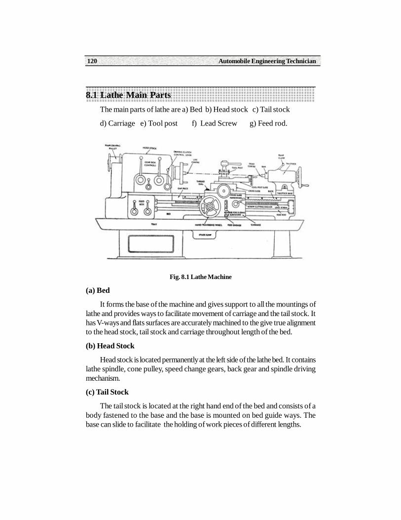
Automobile Engineering Technician120
8.1 Lathe Main PartsThe main parts of lathe are a) Bed b) Head stock c) Tail stock
d) Carriage e) Tool post f) Lead Screw g) Feed rod.
Fig. 8.1 Lathe Machine
(a) Bed
It forms the base of the machine and gives support to all the mountings oflathe and provides ways to facilitate movement of carriage and the tail stock. Ithas V-ways and flats surfaces are accurately machined to the give true alignmentto the head stock, tail stock and carriage throughout length of the bed.
(b) Head Stock
Head stock is located permanently at the left side of the lathe bed. It containslathe spindle, cone pulley, speed change gears, back gear and spindle drivingmechanism.
(c) Tail Stock
The tail stock is located at the right hand end of the bed and consists of abody fastened to the base and the base is mounted on bed guide ways. Thebase can slide to facilitate the holding of work pieces of different lengths.

Paper - I Workshop Technology 121
(d) Carriage
The carriage consists of a saddle and apron. The saddle slides on theguide ways and support the cross slide and compound rest. The apron is thepart of the carriage facing the operator. It contains gears and feed clutches thattransmits motion from the lead screw to carriage and cross slide.Compoundrest is mounted on the cross slide and can be swiveled to required angle toproduce taper.
(e) Tool Post
Tool post is located on the compound rest to hold the cutting tool.
(f) Lead Screw
The lead screw is used for thread cutting operation and it will be in the frontside of the machine passing through carriage.
(g) Feed Rod
It is used for employing automatic feed.
8.2 Lathe OperationsThe following operations are most common on lathe machines.
a) Turning b) Facing c) Reaming
d) Drilling e) Knurling f) Tapertuning.
(a) Turning
Turning in a lathe is to remove excess material from the work piece toproduce a cone shaped or a cylindrical surface. The various types of turningmade in lathe work are 1) Straight turning 2) Shoulder turning 3) Step turning.
Fig. 8.2 Turning

Automobile Engineering Technician122
(b) Facing
Facing is the operation of producing flat end surfaces that is normal to theaxis of rotation. The movement of tool is perpendicular to the axis of workpiece.
Fig. 8.3 Facing
(c) Reaming
It is the operation of finishing and sizing a drilled or bored hole. The reameris held in a tail stock spindle is fed slowly into the work which is revolving at verylow speed.
(d) Drilling
It is the process of making holes on work pieces. The drill is held in tailstock spindle and fed slowly in to the work piece which is revolving in a chuckof the head stock
(e) Knurling
It is the process of indenting the various forms on cylindrical work surfacesby using a knurling tool which is pressed against the rotating work and the designof the knurl rolls over the work and will be reproduced on the work
Fig. 8.4 Knurling

Paper - I Workshop Technology 123
(f) Taper Tuning
A taper may be defined as an uniform increase or decrease in the crosssection of a work piece measured along its length. A conical surface producedon lathe. In taper turning tool moves at an angle to the axis of rotation.
Fig. 8.5 Taper Torning
8.3 Grinding MachinesWorking Principle
Grinding is a metal cutting operation performed by means of a rotatingabrasive wheel that acts as a cutting tool. This is used to finish work piece whichshows a high surface quality, accuracy of shape and dimension.
8.4 Grinding Wheel MaterialsA grinding wheel is a multitooth cutter made up of many hard particles
known as abrasives. The abrasive grains are mixed with a suitable bond, whichacts as a holder when the wheel is in use. Abrasives may be classified in twoprincipal groups a) Natural b) Artificial or manufactured.
(a)Natural : The natural abrasives include sand stone or solid quartz,emery, corundum and diamond.Sandstone or solid quartz is one of the naturalabrasive stones from which grind stones are shaped .The quartz or cuttingagent is relatively soft so that materials harder than quartz cannot be abradedrapdily.
(b)Emery : It is a natural aluminium oxide. It contains 55 to 65% of alumina,the remaining consists of iron oxide and other impurities.
Corundum : It is a natural aluminium oxide. It contain from 75 to 95%aluminium oxide.Both emery and corundum have agreater hardness and betterabrasive action than quartz.
Automobile Engineering Technician124
Diamonds : Diamonds of less than gcm quality are crushed to produceabrasive grains for making grinding wheels.
Artificial :
a) Silicon Carbide
b) Aluminium Oxide
(a) Silicon Carbide : It is manufactured from 56 parts of silica sand, 34parts of powdered coke,2 parts of salt and 12 parts of saw dust in a along.
(b) Aluminium oxide : It is manufactured by heating mineral bauxite, ahydrated aluminium oxide clay containing silica, iron oxide, titanium oxide mixedwith ground coke iron borings
8.5 Applications of GrindingApplications of grinding include the grinding of external and internal
cylindrical grinding , tapered and formed surfaces, gear teeth, threads and otherusing appropriate wheels.
Summary1. Lathe operates on the principle that the excess metal is removed by
using a cutting tool which is fed in to a rotating work piece.
2. According to design and construction the lathes are classified as i)Speedlathe ii)engine lathe iii) Tool room lathe iv)capston and turret lathe
3. Operations which are performed on the lathe are turning, facing,taper turning ,drilling,boring and knurling
4. Grinding machine is used to finish the work piece to much higher accuracyand is performed by means of a rotating abrasive wheel that acts as acutting tool.
5. Grinding wheel materials are two types ie natural and synthetic
Short Answer Type Questions1. Explain the working principle of lathe
2. Name different lathe operations
3. Define knurling
4. Explain the principle of grinding
5. Name grinding wheel materials

Paper - I Workshop Technology 125
Long Answer Type Questions1. Draw a neat sketch of lathe and name the parts
2. Explain about any four lathe operations