Embed Size (px)
DESCRIPTION
The world's leading information resource for plant and asset management engineers.
Citation preview

June 2012
5-11
33-40
25-29
Latest News
Maintenance Myths
Non Destructive Testing
$6.80£4.16€5.00
Embedded Modelling Tools Enhance On-Site Weld Inspection Using Phased Array And Conventional UT.
26-27


5-11
17
25-29
33-40
56-59
72-74
Latest News
Maintenance Best Practice
Non Destructive Testing
Maintenance Myths
How To Write An Effective Lubrication Procedure
Buyers Guide
Contacts
PublisherMichael Dominguez
Editorialeditors/contributing: Jon Barret, Christer Idhammar, Alan FrancePaul Sacker
AdvertisingPaul Clappison
Paul MilesBrian Simpson
ProductionTom Britten
Websitewww.engineeringmaintenance.info
Phonetel: +44(0)1634 731646
Fax: +44(0)1634 731644
AddressMSL Media LTD, Cobalt House,
Centre Court, Sir Thomas Longley
Road, Rochester, Kent, ME2 4BQ
EMS Magazine4
EMS Magazine 5
The AKAZ power plant boasts a capacity of 2x125 MW and is estimated to require three years to complete. One of India’s most outstanding companies, LANCO has been driving growth in the fields of engineering, procurement and construction (EPC) as well as power, solar and natural resources and infrastructure for over twenty-five years and is today uniquely positioned to take the lead in these areas of its influence. Starting on March 27, 2012, SGS will provide quality assurance and quality control services throughout the three-year agreement. SGS is the world’s leader in testing, inspection, certification and verification guaranteeing clients superior specialist examination to ensure compulsory compliance with current regional, national and international standards and regulations. Comprehensive testing and inspection provided by SGS reduces risk and increases quality control during all phases of construction. Unparalleled certification services and verification methods practiced by SGS assist in securing required credentials recognized the world over. SGS expertise in quality assurance and quality control ensures that materials, products, machinery, equipment and industrial facilities
have been manufactured compliant to required and contractual specifications as well as mandatory prerequisites and quality criteria.
Natural Gas : The fuel of choice in state-of-the-art power plants
The industry charged with producing electric power has historically been one of the biggest culprits of pollution worldwide. Strict regulations have been put in place to force the industry to develop new methods aimed at reducing harmful emissions in order to diminish environmental harm. SGS expert testing, inspection, certification and verification guarantees that these stringent directives are met. Modern technologies permit natural gas, the cleanest of the fossil fuels, to be increasingly implemented in generating clean electricity. The use of natural gas has many environmental benefits including the emission of less greenhouse and smog related gasses, positively affecting overall air quality. Due to its abundance, natural gas also offers a cost-efficient alternative to dirty, more expensive resources. Power plants fuelled by natural gas are therefore becoming the popular choice of today’s environmentally responsible and business savvy operators.
The Added Value of SGS Services
SGS meticulously inspects equipment and materials for mechanical defects or regulatory deficits at the manufacturer level as well as on site in order to prevent costly corrective actions during the construction phase or catastrophic shutdowns once the plant is in operation. Expertise in testing, inspection, certification and verification as only SGS can deliver is of paramount priority to maximize asset excellence and value. SGS is proud to have been chosen to assist LANCO in this prestigious endeavour.
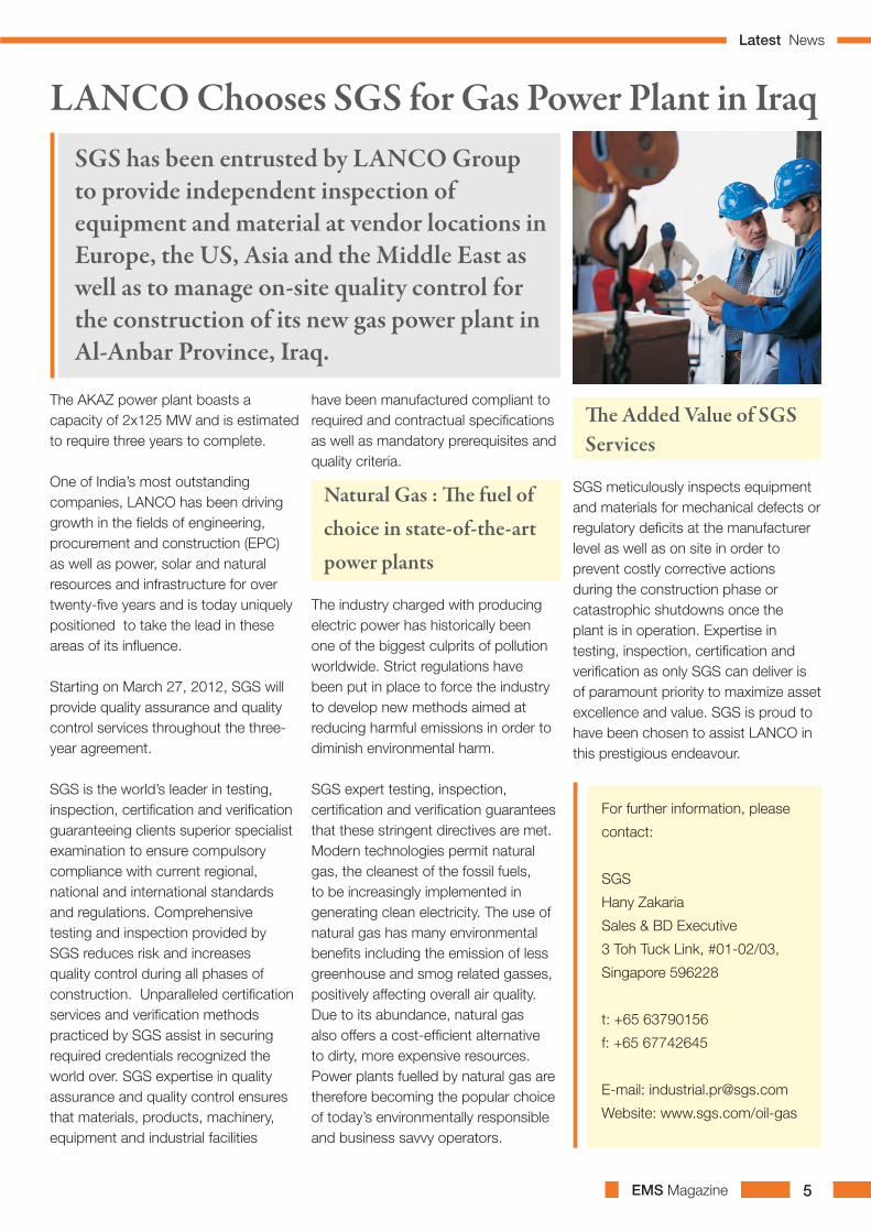
LANCO Chooses SGS for Gas Power Plant in IraqSGS has been entrusted by LANCO Group to provide independent inspection of equipment and material at vendor locations in Europe, the US, Asia and the Middle East as well as to manage on-site quality control for the construction of its new gas power plant in Al-Anbar Province, Iraq.
For further information, please
contact:
SGS
Hany Zakaria
Sales & BD Executive
3 Toh Tuck Link, #01-02/03,
Singapore 596228
t: +65 63790156
f: +65 67742645
E-mail: [email protected]
Website: www.sgs.com/oil-gas
Latest News

EMS Magazine6
EMS Magazine 7
These new ‘T’ Series pumps are designed for high-pressure, high flow applications. The T8045 can pump up to 170 litres per minute at 207 bar while the T8030 can output 102 litres per minute at 310 bar.
In line with all Hydra-Cell pumps, they have a seal-less design thateliminates leaks, hazards and the expense associated with seals and packing. They can operate with a closed or blocked suction line and run dry indefinitely without damage, eliminating downtime and repair costs.
The unique multi-diaphragm design is claimed to handle more abrasives with less wear than gear, screw or plunger pumps. The design also enables maintenance of valves and diaphragms to be undertaken easily in the field without the need for heavy lifting capabilities and this facility will bedemonstrated on the stand.
Visitors to the stand will see five other working displays that highlight the controllability, accuracy and durability of Hydra-Cell pumps for chemical metering, dosing and injection.
New Hydra-CellR pumps on display at Achema
Wanner International will unveil two new Hydra-CellR high performance diaphragm pumps for the first time at Achema 2012 Stand K96, Hall 8.
No More Costly Repairs Thanks To Speedy
Costly engine and machine repair bills are set to be a thing of the past, following the launch of the Husqvarna K760 OilGuard System this week by Speedy, the largest equipment rental and services company in the UK.
Specially designed to prevent engine damage, machine breakdowns and ultimately costly repairs, the K760 OilGuard uses an optical sensor system to detect when the incorrect oil/fuel mixture is used or if there is insufficient oil in the engine, both of which contribute to expensive and often irreparable damage to pistons and cylinders.
To further protect from damage, the K760 OilGuard uses a 15 second flush-out time to detect oil quantity and quality and it immediately reduces engine speed to ‘idle’ to avoid additional damage from occurring. The machine will then not operate until the fuel tank is emptied, and refuelled with correct mix. This is the perfect solution for contractors who use a mix of two-stroke and four-stoke equipment.
The specially coloured K760 OilGuard oil - developed for dusty environments like construction sites - is suitable for use in all two stroke equipment found in the construction industry.
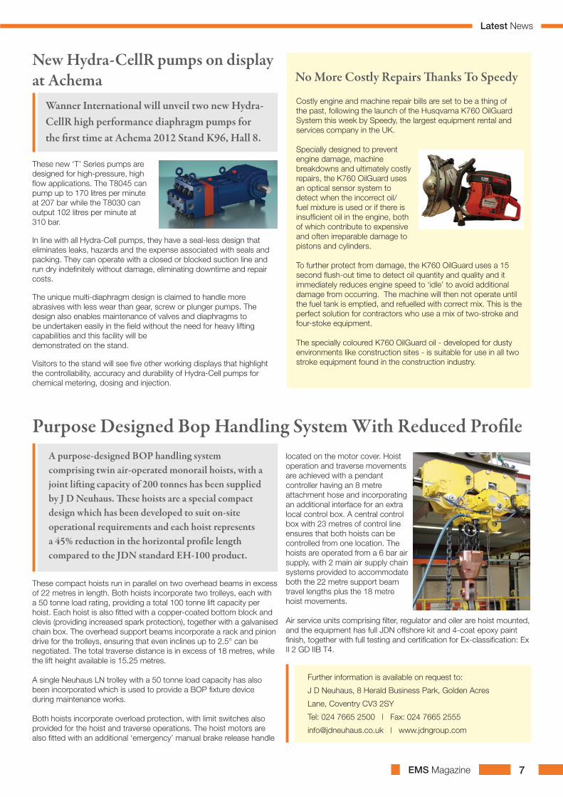
These compact hoists run in parallel on two overhead beams in excess of 22 metres in length. Both hoists incorporate two trolleys, each with a 50 tonne load rating, providing a total 100 tonne lift capacity per hoist. Each hoist is also fitted with a copper-coated bottom block and clevis (providing increased spark protection), together with a galvanised chain box. The overhead support beams incorporate a rack and pinion drive for the trolleys, ensuring that even inclines up to 2.5° can be negotiated. The total traverse distance is in excess of 18 metres, while the lift height available is 15.25 metres.
A single Neuhaus LN trolley with a 50 tonne load capacity has also been incorporated which is used to provide a BOP fixture device during maintenance works.
Both hoists incorporate overload protection, with limit switches also provided for the hoist and traverse operations. The hoist motors are also fitted with an additional ‘emergency’ manual brake release handle
located on the motor cover. Hoist operation and traverse movements are achieved with a pendant controller having an 8 metre attachment hose and incorporating an additional interface for an extra local control box. A central control box with 23 metres of control line ensures that both hoists can be controlled from one location. The hoists are operated from a 6 bar air supply, with 2 main air supply chain systems provided to accommodate both the 22 metre support beam travel lengths plus the 18 metre hoist movements.
Air service units comprising filter, regulator and oiler are hoist mounted, and the equipment has full JDN offshore kit and 4-coat epoxy paint finish, together with full testing and certification for Ex-classification: Ex II 2 GD IIB T4.
Purpose Designed Bop Handling System With Reduced ProfileA purpose-designed BOP handling system comprising twin air-operated monorail hoists, with a joint lifting capacity of 200 tonnes has been supplied by J D Neuhaus. These hoists are a special compact design which has been developed to suit on-site operational requirements and each hoist represents a 45% reduction in the horizontal profile length compared to the JDN standard EH-100 product.
Further information is available on request to:
J D Neuhaus, 8 Herald Business Park, Golden Acres
Lane, Coventry CV3 2SY
Tel: 024 7665 2500 | Fax: 024 7665 2555
[email protected] | www.jdngroup.com
Latest News

EMS Magazine8
The town of Fortrose located on the Moray
Firth, about 10 km north east of Inverness,
was certainly no exception as the small
coastal burgh is exposed to all the elements
the cold North Sea has to throw at it.
So when Inverness based mechanical and
electrical engineers Commissioning Solutions
Scotland were appointed to replace failed
process pumps for the local waste water
treatment facility, careful consideration had
to be given to the insulation material used to
protect the equipment and process flows from
freezing.
For this challenging and exposed environment
David Hawthorn of Commissioning Solutions
Scotland, working in conjunction with thermal
insulation contractors McDonald & Co,
specified Armacell’s Class O Armaflex nitrile
rubber insulation material.
Armaflex offered a number of benefits for
this application over the conventional glass
fibre insulation material which had previously
been used and failed on site. Glass fibre
or mineral wool insulation is reliant on an
easily punctured external foil vapour barrier
to prevent moisture ingress. If this barrier is
compromised, the result is wet insulation that
causes Corrosion Under Insulation (CUI) and
loss of thermal performance, especially in
tough conditions such as those encountered
at the Fortrose waste water treatment works.
As a closed cell foam material, Armaflex
provides an integral vapour barrier against
water ingress and condensation, with no
Armacell Insulation Protects WWT PlantThe Scottish Highlands are no stranger to cold weather but
the winters of 2010 and 2011 were severe even for this part of
the world, with temperatures regularly reaching –15 ºC.
Further information is available on
request:
Armacell UK Ltd, Mars Street, Oldham,
Lancashire OL9 6LY
Telephone: 0161 287 7040
Fax: 0161 633 2685
e-mail: [email protected]
www.armacell.com/uk
The 2.2kW single phase version can deliver 11.5 cfm (325 L/min) FAD capacity @ 8 bar - much greater than any similar compressor operating from this type of power supply.
The compact machine enables users to operate large capacity tools and equipment, but the operating noise level at just 58dB(A) makes it virtually inaudible in most production environments. Using the latest rotary screw technology ensures bot durable performance and optimum energy efficiency. It is part of the Fini ‘Micro’ range which also includes models at 3kW and 4kW (three phase) and capacity up to 20.5 cfm (580 L/min).
Big Compressor Performance From Compact Range
The Micro SE 308M from FPS Air Compressors is claimed to offer the biggest capacity of any compressor operating from a 230V single phase electrical supply.
Further Information:FPS Air Compressors LtdRycote lane, Thame, Oxon OX9 2JSTel: 01844 212233 | Fax: 01844 212620Email: [email protected]: www.fps-compressors.co.uk
New Pig continues its
commitment to innovation
with the introduction of
PIG® Grippy® absorbent
mat. The specially
formulated Grippy®
adhesive backing holds
tight and stays put no
matter what™, but peels
up easily without leaving
residue. NFSI certified to
help reduce slips and falls
by 90% when used as part of a floor safety programme.
For more information visit newpig.co.uk or call 0800
919 900
New Pig introduces exclusive PIG® Grippy® absorbent mat
additional water vapour barrier required. The
material has a moisture resistance factor of
>7,000 µ so even if the material becomes
damaged in some places, it will still provide
protection against condensation and water
ingress as the closed cell structure is built-up
throughout the material’s thickness.
Latest News

EMS Magazine 9
New Hansford Sensor Offers Triaxial Functionality
Hansford Sensors has launched a new triaxial
accelerometer, enabling three axes to be read
simultaneously. The new HS-109 Series vibration
sensor comes complete with the established and
proven M12 connector and is designed to be used
both offline and as a permanently mounted sensor on
industrial machinery.
In order to predict torsional and lateral vibrations in drivelines in rotating machinery supported by computer simulation, ARLA offers engineering services, troubleshooting support, and powerful simulation software (ARMD) also including a fluid-film bearing analysis tool. Engineers experience more details in the annual international rotordynamics seminar (next date: 15-18 October 2012, Cologne, Germany). www.arla.de
Computer Simulation to Support the Vibration Analysis
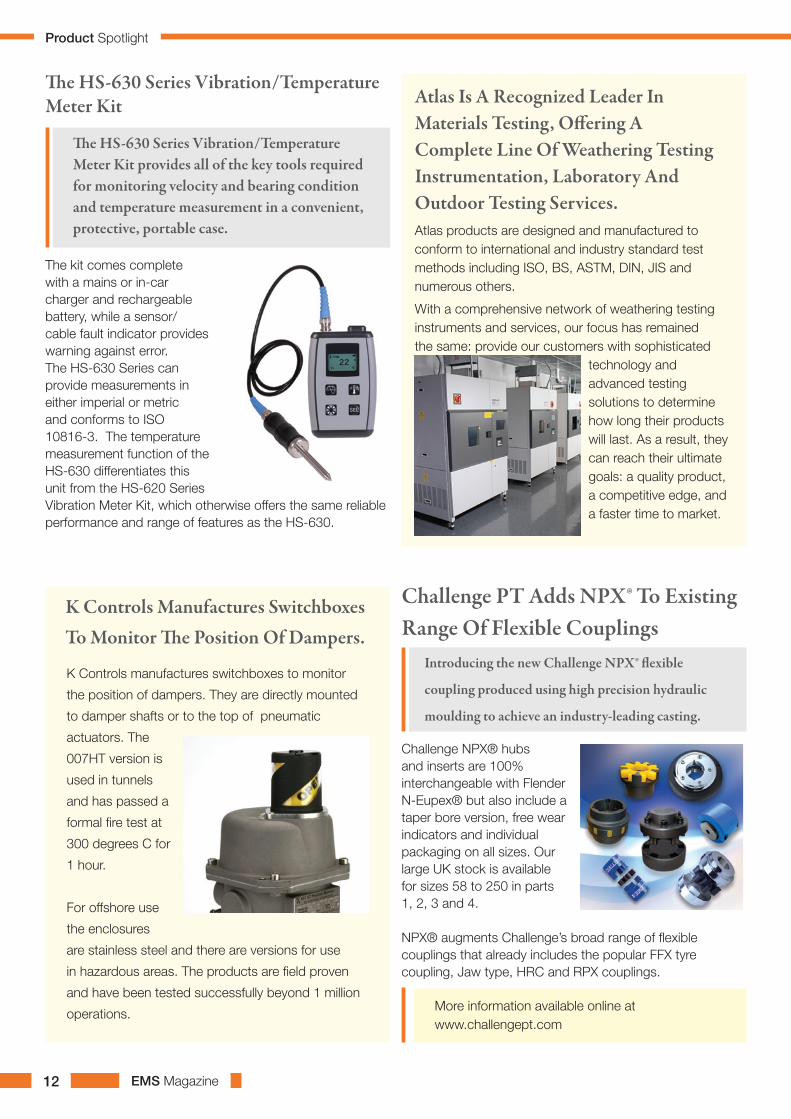
The HS-630 Series Vibration/Temperature Meter Kit provides all of the key tools required for monitoring velocity and bearing condition and temperature measurement in a convenient, protective, portable case. The kit comes complete with a mains or in-car charger and rechargeable battery, while a sensor/cable fault indicator provides warning against error. The HS-630 Series can provide measurements in either imperial or metric and conforms to ISO 10816-3. The temperature measurement function of the HS-630 differentiates this unit from the HS-620 Series Vibration Meter Kit, which otherwise offers the same reliable performance and range of features as the HS-630.
The HS-630 Series Vibration/Temperature Meter Kit
For more information on the extensive range of Hansford Sensors products, please visit:www.hansfordsensors.com.
Vibration Monitoring

EMS Magazine10
ERIKS has launched a new offer that allows engineers to purchase an MC1001 or MCX20 Gates self-assembly crimper for just £1 from the ERIKS Fluid Power Core Competence Centre. The offer underlines ERIKS’ intention to provide cost-savings and unrivalled service to customers at its nationwide network of Service, Repair and Core Competence Centres.
The £1 crimper offer is open to any customer who spends £2,850 on hose and couplings via the starter kit for the MC1001 or alternatively spends £4,950 on hose and couplings via the starter kit for the MCX20.
The MC1001 Crimper can crimp up to 1” wire braid and comes with a range of dies, including ¼”, ½” and ¾”. The MCX20 Starter Kit can crimp up to 1” multi spiral hose and 1” & 2” wire hydraulic hose and includes dies ¼”, ½” , ¾” and 1”.
All starter kit customers will receive free on-site crimper training from Gates, plus certification. For a free crimper demonstration at your premises call your local ERIKS Service Centre on 0845 006 6000.
For further information, please contact: Robyn Bradley, Marketing Executive, ERIKS UKT: +44 (0)121 508 6219 | M: +44(0)7740 452743 [email protected]
Eriks Offers Gates Self-Assembly Crimpers For Just £1
The new HT602D01 is ideal for paper machines and similar applications where high humidity and dusty environments would cause problems for alternative charge mode sensors.
The sensing element of the HT602D01 provides nominal sensitivity of 100mV/g over a frequency range of 0.5 to 8000Hz (±3dB). Unlike many sensors on the market, PCB Piezotronics’ HT602D01 uses a shear sensing element to minimise the base bending and thermal
transient effects that occur in conventional compression mode accelerometers. This renders the HT602D01 accelerometer far less sensitive to unwanted electrical output and leads to more accurate measurement of the actual vibration event.
Featuring a 2-pin MIL connector, the sensor can be used as a drop-in replacement for many existing accelerometers but offers the higher temperature range compared with conventional industrial devices. It is priced
very competitively against charge mode equivalents and possesses a number of other features that assist in making vibration measurements easier. These include a 360° swivel mount that allows for easy cable orientation and minimises the restrictions of cable bend radius; hermetically sealed stainless steel sensor housing with optional PTFE jacketed cables to eliminate the restrictions of lower cost polyurethane cables in the presence of acid fumes; and case isolated to prevent ground loops.
All standard PCB sensors and products are supplied with a two-year warranty and the company also offers to all customers, at no charge, 24-hour emergency telephone support. This service makes product and application
support available to customers and end-users, day or night, seven days per week.
PCB Piezotronics Introduces New High Temperature Icp® Industrial Accelerometer
PCB Piezotronics, a world leader in vibration, acoustic, pressure, force and torque sensors, has introduced a new high temperature ICP® (IEPE) industrial accelerometer that is capable of operation up to 163°C.
PCB Piezotronics Ltd,
7 Paynes Park, Hitchin,
Hertfordshire, SG5 1EH.
Tel: +44 (0) 1462 429710,
Fax: +44 (0) 1462 429798.
Email: [email protected]
Web site:
http://www.pcbsensors.
co.uk
Vibration Monitoring

EMS Magazine 11
They provide generalised protection for downstream airline production equipment, as well as many specialised application requirements including instrument air quality, printing and gas analysing devices etc. The HPD unit provides an ideal localised installation where high quality air is a critical requirement. They ensure a low dewpoint (-40°C) at point of use, or where an existing air supply has only been dried to a refrigerant air dryer quality of +3°C dewpoint.
The HPD dryer range utilises a disposable desiccant adsorption cartridge to
effectively remove moisture from a compressed air supply. The unique housing design allows the cartridge to be changed within only two minutes, without the need for any specialised tools. A pressure dewpoint of -40°C can be achieved with no energy consumption, no power required and no expensive air loss from the use of purged air.
Three HPD dryers are available offering flow capacities of 59, 122 and 210m3. The aluminium desiccant molecular sieve is easily replaceable and is incorporated in an aluminium housing, pressure rated
to 16 barg. The units are CE rated and operate independent of any separate power supply.
Dryers Provide -40ºC Dewpoint At Point-Of-Use For Maximum Economy
The HPD range of ‘point of use dryers’ from Hi-line Industries are compact and cost effective and feature a ‘minimum downtime’ cartridge change. They are ideally suited for remote installations, or wherever there may be only limited access available.
Further information is available from:
Tel: 01283 533377
Fax: 01283 533367
e-mail: [email protected]
www.hilineindustries.com
At the core of the suite is Infor10 ERP Business (SyteLine), a leading ERP solution specialized for the high tech industry, integrated through Infor10 ION technology with Infor10 PLM Discrete (PLM8) to help track, manage, monitor, and analyze products throughout the product lifecycle. These applications will help Oxford Instruments continue to grow by delivering standardized business processes and improving productivity across operations in China, Germany, Japan, the United States, and the United Kingdom. The applications replace a portfolio of legacy systems at Oxford Instruments, and are
expected to help the company improve productivity and deliver on its strategy to achieve 14 percent compound annual revenue growth by 2014. ERP Business will support a set of core processes throughout Oxford Instruments including customer facing processes such as order taking. By offering improved connectivity and integration with existing applications, ERP Business enables ‘straight-through processing’ where the various components of customer requirements are automatically sent to the relevant companies for fulfilment, without needing additional data entry. ERP Business is designed to eliminate
disparate systems, enable consistent, company-wide training and accelerate the integration of any further acquisitions. “We have not just bought a product, we have invested in a partner and have chosen Infor because the company’s expertise enables them to cover the majority of our requirements out-of-the-box,” said Gary Wearing, Director of Oxford Instruments NanoScience division. “We have some demanding milestones for the time and cost of implementation, and we will be measuring productivity improvements to make sure that the application delivers. But we are confident that both the company and the technology we have chosen will help us to achieve our growth strategy.”
Oxford Instruments Measures Up with InforInfor, a leading provider of business application software
serving more than 70,000 customers, today announced
that Oxford Instruments plc, has chosen a suite of
applications from Infor to support global operations.
Latest News
EMS Magazine12
Atlas products are designed and manufactured to conform to international and industry standard test methods including ISO, BS, ASTM, DIN, JIS and numerous others.
With a comprehensive network of weathering testing instruments and services, our focus has remained the same: provide our customers with sophisticated
technology and advanced testing solutions to determine how long their products will last. As a result, they can reach their ultimate goals: a quality product, a competitive edge, and a faster time to market.
Atlas Is A Recognized Leader In Materials Testing, Offering A Complete Line Of Weathering Testing Instrumentation, Laboratory And Outdoor Testing Services.
K Controls manufactures switchboxes to monitor
the position of dampers. They are directly mounted
to damper shafts or to the top of pneumatic
actuators. The
007HT version is
used in tunnels
and has passed a
formal fire test at
300 degrees C for
1 hour.
For offshore use
the enclosures
are stainless steel and there are versions for use
in hazardous areas. The products are field proven
and have been tested successfully beyond 1 million
operations.
K Controls Manufactures Switchboxes To Monitor The Position Of Dampers.
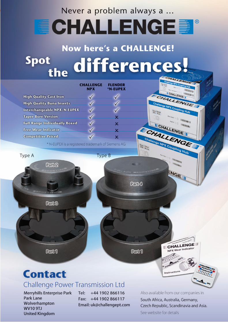
Challenge NPX® hubs and inserts are 100% interchangeable with Flender N-Eupex® but also include a taper bore version, free wear indicators and individual packaging on all sizes. Our large UK stock is available for sizes 58 to 250 in parts 1, 2, 3 and 4.
NPX® augments Challenge’s broad range of flexible couplings that already includes the popular FFX tyre coupling, Jaw type, HRC and RPX couplings.
Challenge PT Adds NPX® To Existing Range Of Flexible Couplings
Introducing the new Challenge NPX® flexible
coupling produced using high precision hydraulic
moulding to achieve an industry-leading casting.
More information available online at www.challengept.com
The kit comes complete with a mains or in-car charger and rechargeable battery, while a sensor/cable fault indicator provides warning against error. The HS-630 Series can provide measurements in either imperial or metric and conforms to ISO 10816-3. The temperature measurement function of the HS-630 differentiates this unit from the HS-620 Series Vibration Meter Kit, which otherwise offers the same reliable performance and range of features as the HS-630.
The HS-630 Series Vibration/Temperature Meter Kit
The HS-630 Series Vibration/Temperature Meter Kit provides all of the key tools required for monitoring velocity and bearing condition and temperature measurement in a convenient, protective, portable case.
Product Spotlight
EMS Magazine14
Thermal Energy International has installed a total of 92 steam traps throughout the facility’s process plant, which has removed the problems of mechanical steam trap failure and high maintenance costs.
The company’s most important site in Italy for technology, innovation and development of pharmaceutical products, the management asked Thermal Energy International to conduct a survey of its mechanical traps, which were regularly failing open, partly open and closed, necessitating both scheduled and unscheduled maintenance. To corroborate its findings, Thermal Energy International undertook a metered test on a process application and then carried out a positive bucket test.
The report from Thermal Energy International on the 51 steam traps
surveyed found that 30% had failed, resulting in an estimated 757 tonne/y of steam being lost each year at a cost of about 31,000 euros. As a result of the project, the company would not only be saving costs in energy and a reduction in maintenance but would also reduce its start-up time and reduce its CO2 emissions by a substantial 131 tonnes.
Thermal Energy International demonstrated that by replacing the existing traps with the GEM venturi orifice design, blocked steam traps could be prevented from impacting on production and start-up times, and by efficiently returning condensate back to the boilers maximum energy savings would be achieved. All 92 mechanical traps installed on industrial steam and some clean steam applications including PSG, distillers, air conditioning units and heat exchangers
were replaced with appropriately sized GEM steam traps.
Such has been the success of Thermal Energy International’s GEM steam traps that the company plans to install further GEM traps as further improvements and investment is made at the manufacturing facility. Instead of utilising a valve mechanism to close off steam for maximum energy and water conservation, the highly efficient GEM steam traps use the venturi orifice design to effectively drain condensate from the steam system. As the GEM steam traps have no moving parts to wedge open or fail, they provide the ultimate in reliability necessitating only minimal maintenance and requiring no spares, testing or monitoring equipment.
Available in a wide range of sizes for a full cross section of applications, the hardwearing GEM steam traps are manufactured from corrosion resistant stainless steel and are guaranteed for 10 years, obviating the need for repair or replacement. The GEM steam traps provide a fast payback - on some processes within a matter of days - from reduced energy costs and increased equipment reliability due to a reduction in damaging condensate in steam systems. In addition they improve product processing by enhancing the quality of steam and also reduce equipment repairs, downtime and replacement costs.
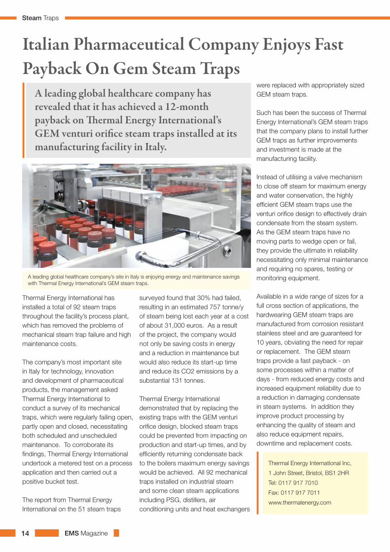
Italian Pharmaceutical Company Enjoys Fast Payback On Gem Steam Traps
A leading global healthcare company has revealed that it has achieved a 12-month payback on Thermal Energy International’s GEM venturi orifice steam traps installed at its manufacturing facility in Italy.
A leading global healthcare company’s site in Italy is enjoying energy and maintenance savings with Thermal Energy International’s GEM steam traps.
Thermal Energy International Inc,
1 John Street, Bristol, BS1 2HR
Tel: 0117 917 7010
Fax: 0117 917 7011
www.thermalenergy.com
Steam Traps
EMS Magazine 15
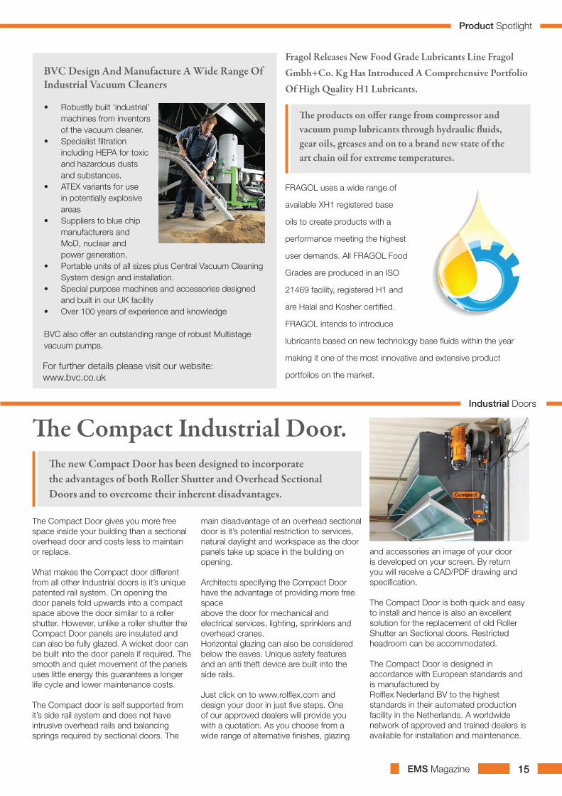
The Compact Door gives you more free space inside your building than a sectional overhead door and costs less to maintain or replace.
What makes the Compact door different from all other Industrial doors is it’s unique patented rail system. On opening the door panels fold upwards into a compact space above the door similar to a roller shutter. However, unlike a roller shutter the Compact Door panels are insulated and can also be fully glazed. A wicket door can be built into the door panels if required. The smooth and quiet movement of the panels uses little energy this guarantees a longer life cycle and lower maintenance costs.
The Compact door is self supported from it’s side rail system and does not have intrusive overhead rails and balancing springs required by sectional doors. The
main disadvantage of an overhead sectional door is it’s potential restriction to services, natural daylight and workspace as the door panels take up space in the building on opening.
Architects specifying the Compact Door have the advantage of providing more free spaceabove the door for mechanical and electrical services, lighting, sprinklers and overhead cranes.Horizontal glazing can also be considered below the eaves. Unique safety features and an anti theft device are built into the side rails. Just click on to www.rolflex.com and design your door in just five steps. One of our approved dealers will provide you with a quotation. As you choose from a wide range of alternative finishes, glazing
and accessories an image of your door is developed on your screen. By return you will receive a CAD/PDF drawing and specification. The Compact Door is both quick and easy to install and hence is also an excellent solution for the replacement of old Roller Shutter an Sectional doors. Restricted headroom can be accommodated.
The Compact Door is designed in accordance with European standards and is manufactured byRolflex Nederland BV to the highest standards in their automated production facility in the Netherlands. A worldwide network of approved and trained dealers is available for installation and maintenance.
The Compact Industrial Door.The new Compact Door has been designed to incorporate the advantages of both Roller Shutter and Overhead Sectional Doors and to overcome their inherent disadvantages.
FRAGOL uses a wide range of
available XH1 registered base
oils to create products with a
performance meeting the highest
user demands. All FRAGOL Food
Grades are produced in an ISO
21469 facility, registered H1 and
are Halal and Kosher certified.
FRAGOL intends to introduce
lubricants based on new technology base fluids within the year
making it one of the most innovative and extensive product
portfolios on the market.
Fragol Releases New Food Grade Lubricants Line Fragol Gmbh+Co. Kg Has Introduced A Comprehensive Portfolio Of High Quality H1 Lubricants.
The products on offer range from compressor and vacuum pump lubricants through hydraulic fluids, gear oils, greases and on to a brand new state of the art chain oil for extreme temperatures.
• Robustly built ‘industrial’ machines from inventors of the vacuum cleaner.
• Specialist filtration including HEPA for toxic and hazardous dusts and substances.
• ATEX variants for use in potentially explosive areas
• Suppliers to blue chip manufacturers and MoD, nuclear and power generation.
• Portable units of all sizes plus Central Vacuum Cleaning System design and installation.
• Special purpose machines and accessories designed and built in our UK facility
• Over 100 years of experience and knowledge
BVC also offer an outstanding range of robust Multistage vacuum pumps.
BVC Design And Manufacture A Wide Range Of Industrial Vacuum Cleaners
For further details please visit our website: www.bvc.co.uk
Industrial Doors
Product Spotlight

EMS Magazine 17
Yes, I think that most maintenance
organizations are overstaffed, not
necessary with own staff, but they
use more total maintenance hours
than necessary. Total maintenance
hours include your own internal
hours, overtime hours and contractor
hours. As an example from pulp and
paper industry: a newsprint mill or
a linerboard mill making 600,000
tons recycled paper per year on two
machines is very good at less than
0.3 total maintenance hours per ton
while most operations we have been
working with are using about 0.5 total
maintenance hours per ton.
If you work in a highly reactive
maintenance organization you will be
trapped in a circle of despair and you
are wasting too much time on doing
the wrong things. A circle of despair is
when you have to react to a problem
on a short notice. You then have to
correct the problem as fast as possible;
the quality of the correction will then
be less than perfect. This leads to that
it soon has to be repaired again and
this circle of despair will continue and
absorb all time you could have used to
do the right things.
The reasons why most maintenance
organizations are using more total
maintenance hours than necessary
is that they waste too much time on
doing the wrong things and this is
because they work in a system that
does not allow people to be as efficient
as they can be. To correct the system
is the responsibility of leadership. It is
the most important thing a leader can
do. I use the term leader because too
many managers are just managing
status quo.
Some examples on doing the wrong things include:
Maintenance is driven by cost
instead of actions that drives
cost.
Maintenance managers become
more focused on the budget
constraints then on delivering
reliability. Instead the focus must be
to improve total reliability. It is well
proven that a focus on improving
reliability will produce faster
quality production throughput and
lower costs.
Reacting to Equipment
breakdowns.
Our studies show that between
50% and 70% of all maintenance
work is avoidable. The reason
for this is that the basics of
maintenance prevention,
inspections and the right operating
practices concurrently with
planning, scheduling and execution
are not done well.
Reacting on emotional priorities.
Still today most maintenance
organizations are viewed as service
providers and not providers of
equipment reliability in an equal
partnership with operations.
Operations are still viewed as the
customer ordering work from the
maintenance organization. Among
many other wrong behaviors this
leads to a mindset to please the
customer by responding to their
requests instead of delivering what
is best for the business.
Top Management oxymoron.
Also top management agrees to all
of the above but often responds,
“Reliability is top priority but we must
cut costs first”
I call this statement an oxymoron
because the fact is that better reliability
drives down costs while a focus on
lower costs drives down reliability. It is a
very difficult predicament to solve. The
solution to achieve consistently and
sustainable lower costs is long term,
but as a manager you are working in a
system that forces you to make short
decisions.
The focus on cutting costs is
in most organizations done by
deferring maintenance work. A
valid maintenance job can never be
eliminated, it can only be postponed
and you will then often pay much more
later.
If cutting costs by elimination of people
without any improvements in people
productivity will result in increased
maintenance hours. You might have
fewer employees but more overtime
and contractor hours. Short term
savings and long term loss.
If the focus is to improve total reliability you will see short term cost and long term continuously improved production throughput and lower costs.
Are Most Maintenance Organizations Overstaffed?Christer Idhammar is a world-renowned and multiple award winning Reliability and Maintenance Consultant and Guru. He is the Founder and CEO of IDCON, INC in Raleigh NC, USA; A reliability and maintenance training and consulting company to the Industry worldwide since 1972. www.idcon.com
Maintenance Best Practice

EMS Magazine 19
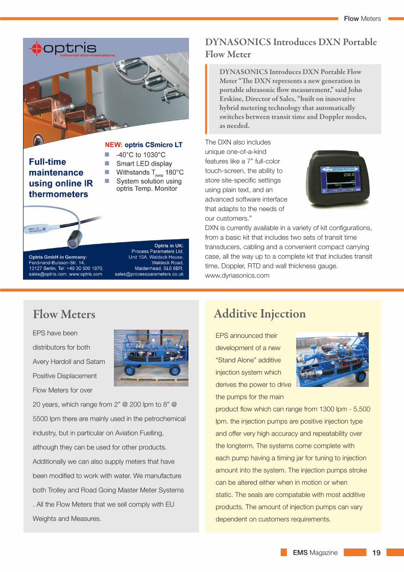
The DXN also includes unique one-of-a-kind features like a 7” full-color touch-screen, the ability to store site-specific settings using plain text, and an advanced software interface that adapts to the needs of our customers.”DXN is currently available in a variety of kit configurations, from a basic kit that includes two sets of transit time transducers, cabling and a convenient compact carrying case, all the way up to a complete kit that includes transit time, Doppler, RTD and wall thickness gauge. www.dynasonics.com
DYNASONICS Introduces DXN Portable Flow Meter
DYNASONICS Introduces DXN Portable Flow Meter “The DXN represents a new generation in portable ultrasonic flow measurement,” said John Erskine, Director of Sales, “built on innovative hybrid metering technology that automatically switches between transit time and Doppler modes, as needed.
Flow Meters Additive InjectionEPS have been
distributors for both
Avery Hardoll and Satam
Positive Displacement
Flow Meters for over
20 years, which range from 2” @ 200 lpm to 8” @
5500 lpm there are mainly used in the petrochemical
industry, but in particular on Aviation Fuelling,
although they can be used for other products.
Additionally we can also supply meters that have
been modified to work with water. We manufacture
both Trolley and Road Going Master Meter Systems
. All the Flow Meters that we sell comply with EU
Weights and Measures.
EPS announced their
development of a new
“Stand Alone” additive
injection system which
derives the power to drive
the pumps for the main
product flow which can range from 1300 lpm - 5,500
lpm. the injection pumps are positive injection type
and offer very high accuracy and repeatability over
the longterm. The systems come complete with
each pump having a timing jar for tuning to injection
amount into the system. The injection pumps stroke
can be altered either when in motion or when
static. The seals are compatable with most additive
products. The amount of injection pumps can vary
dependent on customers requirements.
Flow Meters

EMS Magazine20
The Company Barriquand is specialized in the design and the supply of Easy to Clean All Welded Plate Heat Exchangers called PLATULAR® and patented by our company since many years.
The PLATULAR® is of a robust construction manufactured from either stainless steel or higher alloys. To enable it to be broadly used with all different types of media, an independant and generous spacing can be provided between the heat transfer plates, whilst removable access covers and optional wash systems simplify routine cleaning and maintenance.
More information are directly available on our website at the address: http://www.barriquand.com
The SCHMIDT®
range of compact
shaft couplings
are available
through Abssac
limited, offers a
torsionally stiff
performance that
compensates for
unusually high
variable parallel shaft offsets, up to a staggering 275
mm. The well-balanced design allows rotation of the
shaft coupling, without side loads and is capable of
transmitting torque from 35 Nm up to 6610 Nm from
the compact designs . 2D and 3D CAD format drawings
are available for all model types.
Unique Offset Shaft Coupling
For further information why not look at our web
site www.abssac.co.uk for further details.
Tel : ABSSAC 01386 421005
Packed with useful features
and functions, including
Automatic Calibration,
Calculates and adusts
for pressure and Internal
Logging as standard to
name just some. Designed
to be fully portable with the
user in mind to allow only
a few simple steps to achieve rapid, accurate and reliable
measurements on the go.
AMS Dewpoint HygrometersMoisture control between -1100C (-1660F) to +200C
(+680F) dewpoint can easily be done using these small
and lightweight Handheld Dewpoint Hygrometers
from Alpha Moisture Systems, the Models SADPmini
and SADPmini-Ex.
Find out more and get a quote here at:
www.dew-point.com or email: [email protected]
or call: +44 (0) 1274 733 100.
Recently, TTL gained added respect
in this strictly monitored field by
passing a meticulous manufacturing
audit by one of the largest and
foremost pharmaceutical companies,
worldwide. FG lubes, formulated
for the pharmaceutical industry,
range from popular multipurpose
greases and oils to OEM approved
temperature/pressure lubricants used in complex, high speed
tablet presses. Food processing, beverage and many other
essential companies utilize these proven, cost saving, FG
products in all types of applications, on a daily basis; PTFE
fortified bearing greases, long life gear and compressor oils,
water resistant greases, and much, much more.
Tribology/TechLube (TTL) has originated, specified and produced the highest quality, synthetic and specialty, Food Grade (FG) rated lubricants for over 30 years
Please visit www.tribology.com for a comprehensive
overview of TTL’s highly effective capabilities!
Product Spotlight
Couplings

EMS Magazine 21
LICO Electronics GmbH Klederinger Str. 31A-2320 KlederingAustriaTel + 43 1 706 43 00Fax + 43 1 706 41 31email: [email protected]
LICO Hungaria Kft Raba u. 4H-2030 Erd,HungaryTel + 36 23 520 113Fax + 36 23 520 115email: [email protected]
LICO Mecatronic S.R.L.Str.Bucinului Nr.2B / 19RO-540526 Targu-MuresRomaniaTel. +40 365 807 497Fax: +40 365 434 999Email: [email protected]
in Engine-rooms, Wind generators, Power Plants, Ovens, Generators, Dryers, Trains, Gas turbines, Heating rooms, Factories, Inventories and many more. Reliable 2- or 4-wire N/O or N/C switches, FM approved, connect to your existing alarm system or take the comprehensive LICO HDL &
Detect Heat & OverheatBefore There Is Fire Or Explosion
Stand-Alone or intermitting Alarmpanel HDL to secure life and your values by “in advance monitoring”.
Learn more by:www.prevent-a-fire.eu or www.fenwal-direct.eu
Detect Heat and Overheat (and Fire) and report/alarm from 60 – 385°C
DayCor® Corona cameras see and
show where insulation is compromised;
where corona rings are missing; which
insulators are left unwashed; where are
the punctured insulators; where are
air gaps in a generator; what is wrong
with a switchgear’s design; where are
broken-strands on conductors, etc.
When selecting technologies to monitor
electrical assets’ conditions it is worth
knowing that corona cameras provide
immediate pinpointed imaging of the
faulty components that need attention.
Existing complimenting technologies
such as thermography and acoustics
cannot pinpoint the emitting sources.
Thermography indicates hot spots
which are not created by partial
discharge such as corona and acoustic
devices can indicate the existence of
discharges without showing their exact
location.
Ofil offers a range of products for
various inspection modes. DayCor®
Superb is a very popular hand held
corona camera used worldwide.
DayCor® ROM Ofil is a stabilized
airborne system for most helicopters
made and mounts. UVollé is a
compact corona camera for daily use
by maintenance engineers providing
immediate information in real time.
DayCor® Corona Cameras Detect Partial & Full Electrical Discharges On Medium And High Voltage Constructions And Display Them.
Information obtained is used by maintenance teams to monitor and control the conditions of their assets.
For more information please
visit: www.ofilsystems.com
Condition Monitoring
Explosion Protection

EMS Magazine22
By ensuring the correct information is available on various processes, case studies and costings, selecting the best descaling option for your building project is simple!
AquaVantage Hard Water Treatment has been developed over 20 years by Vaughan Industries Limited. Their hard water treatment is the most powerful and effective treatment of its type available. Their unique process ensures that water stays treated for up to 7 days so that the last appliance and shower head receives treated water. This long treatment life allows
the process to treat cold and hot water supplies effectively and also assists with Bio Film and Bacteria control in stored water, Cooling Towers, Jacuzzis and Swimming Pools.
The unique process is currently being used extensively throughout the UK, China, South Africa, USA and other countries. It is easily treating pipe diameters of 15mm to 5ft in diameter.
All hard water treatments are effective in varying degrees at controlling hard water effects in plumbing, plant, appliances and facilities. However, most processes developed by others do not possess the power and effect to descale all of the pipe line and appliances throughout any building from one point, in any water hardness levels, in spite of claims made.
Only a truly effective process can keep calorifiers cleaner, lengthen the operational life of Steam Generator Humidifiers, keep wall mounted hot water boilers in good order and maintain the whole plumbing arrangements in any building in a scale free condition. This can only be
achieved with a process that has a long and effective “life” in water which will descale plumbing and appliances in a very short time and continue keeping them free of hard scale deposits.
The unique system called AquaVantage Hard Water Treatment does exactly this, usually from the rising main, in any building or industrial process where all of the water will become softer as the surface tension is reduced. This enables the water to descale existing plumbing and appliances as well as reduce further accumulations.
AquaVantage Hard Water Treatment is built with a 20 year design life and requires no maintenance. It carries a warranty of 3 years and requires electrical power to operate. Fitting is quick and simple, no mess, no plumbing and no inconvenience.
First Choice in Hard Water Treatments.There are many hard water treatments available to engineering and design companies, but how can you choose the best one?
Venturi Seperator 150mm pipes with and without treatment.
For further information please contact:-Main UK Sales AgentMr Trevor Best,Aquair on 01908 [email protected]
A treated cooler on a 273mm pipe after 11 months. Before fitting it would normally have 23 tubes blocked solid in under 8 months.
Descaling

EMS Magazine 23
The Swedish Centre for Maintenance Management, a trade association for reliability and maintenance suppliers in the Nordic countries, grants the award to highlight maintenance efforts resulting in profitability increases on behalf of the customer. SPM participated with SPM HD®, the new and patented measuring technique for shock pulse measurement on rotating machinery. SPM HD®, launched in 2011, has attracted much interest in industries everywhere, primarily for its capacity to deliver reliable condition information on low speed machinery.The award winner was presented on the evening of March 15, in conjunction with an industry banquet at the tradeshow Underhåll 2012 in Gothenburg, Sweden. SPM earned the award with the following justification: ”SPM HD® is the result of long term development with a high level of innovation. The product efficiently improves reliability work in an important application area of industrial maintenance.”
SPM Wins Prestigious Industry Award For SPM HD®SPM Instrument proudly announce our winning of the Scandinavian First Maintenance Service Award 2012.
SPM Instrument UK LimitedTel +44 1706 835331 | Fax +44 1706 260640 www.spminstrument.co.uk | [email protected]
EMS Magazine24
Unique “Bidirectional Hydrodynamic Drive” (BHD) patented design provides minimum discharge of water – less than 1% of total system flow – during cleaning while maximizing filter screen cleaning efficiency. The only automatic filter offering a “no leak” body design; 316 Stainless body and screen construction provides superior component longevity. Virtually limitless flow rates and various degrees of filtration are available from 1500 to 10-micron. Made in USA.VAF Filtration Systems ~ www.vafusa.com ~ +1 303 425 4242
VAF specializes in the Engineering & Manufacture of automatic self-cleaning individual, modular and skid mounted filtration systems that include integrated controls and valves for Cooling Towers, Pre-RO, Desalination, Water & Waste Water applications.
When the pressure loss (DP)
across the filter has reached
7 psi / 0.5 bar, cleaning is
performed by motor driven,
rotating, stainless steel
brushes. The flushing valve
opens and pressure in the
flushing chamber exhausts the
collected dirt. The cleaning
process takes 8-10 seconds,
with no interruption of flow.
The screen element is 316 stainless steel wedgewire, down
to 200um.
The BE-Series automatic electric filtersThe BE-Series automatic electric filters combine the advantages of high quality filtration from different water sources with a self-cleaning feature that does not rely on hydraulic scanner nozzles. Flushing can occur at pressures as low as 15 psi / 1 bar.
VAF Filtration Systems ~ www.vafusa.com ~ +1 303 425 4242
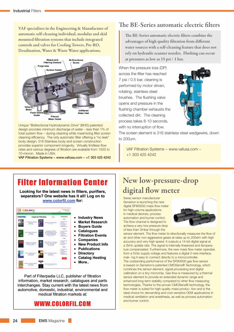
Swiss sensor manufacturer Sensirion is launching the new digital SFM3000 mass flow meter for high-volume applications in medical devices, process automation and burner control. The flow channel is designed to achieve a very low pressure drop of less than 3mbar through the sensor element. The flow meter bi-directionally measures the flow of air and other non-aggressive gases at rates up to 200slm with high accuracy and very high speed. It outputs a 14-bit digital signal at a 2kHz update rate. The signal is internally linearized and tempera- ture compensated. Furthermore, the new mass flow meter operates from a 5Vdc supply voltage and features a digital 2-wire interface, mak- ing it easy to connect directly to a microcontroller.The outstanding performance of the SFM3000 gas flow sensor is based on Sensirion’s patented CMOSens® Technology, which combines the sensor element, signal processing and digital calibration on a tiny microchip. Gas flow is measured by a thermal sensor element to provide an extended dynamic range and enhanced long-term stability compared to other flow measuring technologies. Thanks to the proven CMOSens® technology, the flow meter is suited for high-quality mass produc- tion and is the ideal choice for demanding and cost-sensitive OEM applications in medical ventilation and anesthesia, as well as process automation and burner control.
New low-pressure-drop digital flow meter
Industrial Filters

EMS Magazine26
Embedded Modelling Tools Enhance On-Site Weld Inspection Using Phased Array And Conventional UT.
The wider use of multi-technique ultrasonic instruments combining phased array, TOFD and conventional UT has increased the number of parameters to be controlled by the ultrasonic technician.
Visualization and modelling tools are generally of great
help to ensure that all settings are in accordance with the
inspection technique and code requirements. These tools
are now available on portable phased array flaw detectors
and can now be used in real time, on-site inspections.
The ASTM E2700, Standard Practice for Contact Ultrasonic
Testing of Welds Using Phased Arrays, is used as an
example of typical code requirements. This practice refers
to the use of angle beam inspection with either sectorial
scan (S-scan) or linear scan (L-scan), also called electronic
scan (E-scan). The practice is based on its equivalent
standard for conventional UT ASTM E164 (BS EN1714 Non
destructive testing of welded joints, Ultrasonic testing of
welded joints).
A typical setup for workflow for an inspector undertaking
weld inspection includes the following steps, defined via the
ScanPlan: define inspection parameters, select probe and
wedge, define the “part” to be inspected, define focal laws,
position probes on parts and set up the encoder. The final
step would be Calibration. These are the most common
steps that an inspector has to go through before going
on-site.
The user interface of the phased array flaw detector
discussed here was designed to match this intuitive
workflow as closely as possible. One important aspect
to notice is that most of these steps refer to examination
procedure and scan plan requirements. Once the inspection
technique has been established, which essentially include
probes and scans, quantity selection, as well as the type
of scan; the details of the scan plan can be defined. This
approach is in accordance with the standard practice
which states that the phased array scanning procedure for
welds shall be established using a scan plan indicating the
stand-off positions for the probes and the appropriate beam
angles.
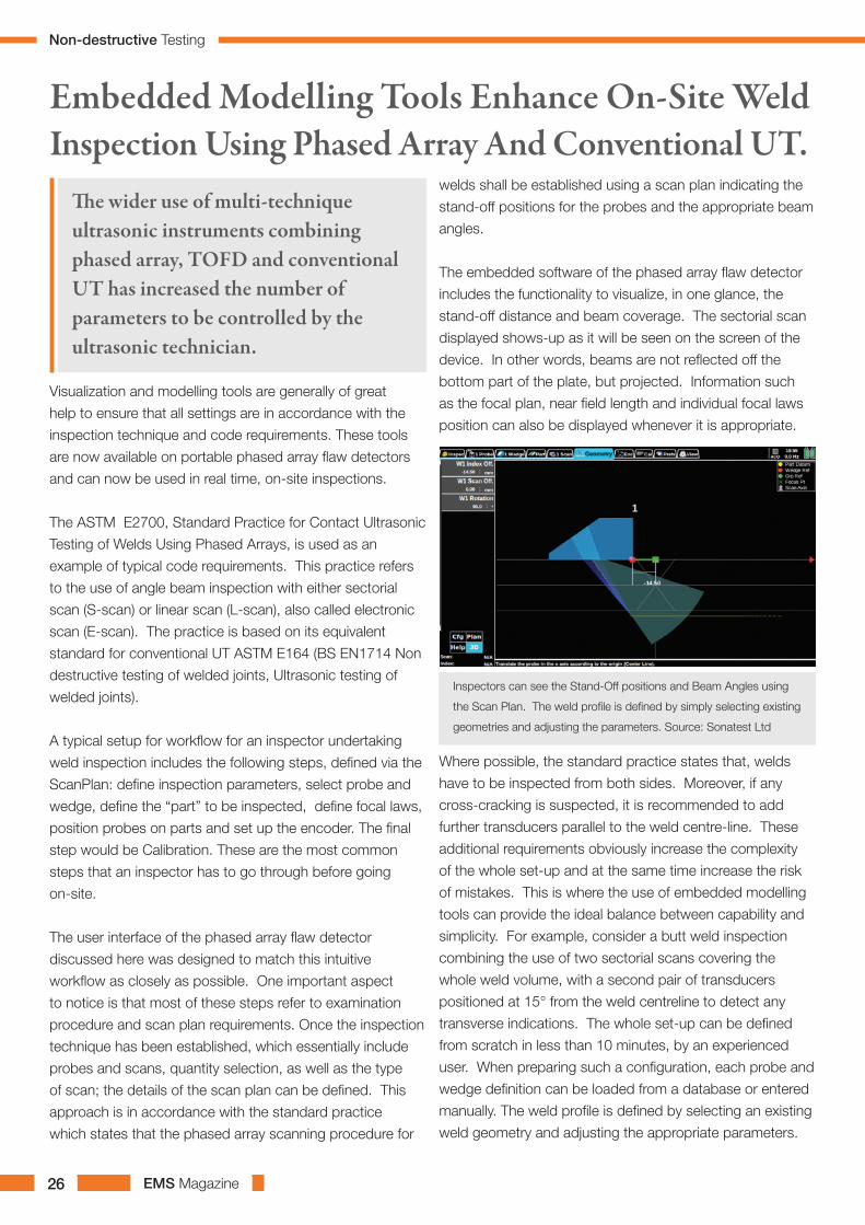
The embedded software of the phased array flaw detector
includes the functionality to visualize, in one glance, the
stand-off distance and beam coverage. The sectorial scan
displayed shows-up as it will be seen on the screen of the
device. In other words, beams are not reflected off the
bottom part of the plate, but projected. Information such
as the focal plan, near field length and individual focal laws
position can also be displayed whenever it is appropriate.
Inspectors can see the Stand-Off positions and Beam Angles using
the Scan Plan. The weld profile is defined by simply selecting existing
geometries and adjusting the parameters. Source: Sonatest Ltd
Where possible, the standard practice states that, welds
have to be inspected from both sides. Moreover, if any
cross-cracking is suspected, it is recommended to add
further transducers parallel to the weld centre-line. These
additional requirements obviously increase the complexity
of the whole set-up and at the same time increase the risk
of mistakes. This is where the use of embedded modelling
tools can provide the ideal balance between capability and
simplicity. For example, consider a butt weld inspection
combining the use of two sectorial scans covering the
whole weld volume, with a second pair of transducers
positioned at 15° from the weld centreline to detect any
transverse indications. The whole set-up can be defined
from scratch in less than 10 minutes, by an experienced
user. When preparing such a configuration, each probe and
wedge definition can be loaded from a database or entered
manually. The weld profile is defined by selecting an existing
weld geometry and adjusting the appropriate parameters.
Non-destructive Testing
EMS Magazine 27
Technician Tips:Common steps that an inspector should go through before on-site inspection:
• Define Inspection parameters• Choose probe & wedge• Define part being inspected• Define focal laws• Position probes on part• Set up Encoder• Calibrate
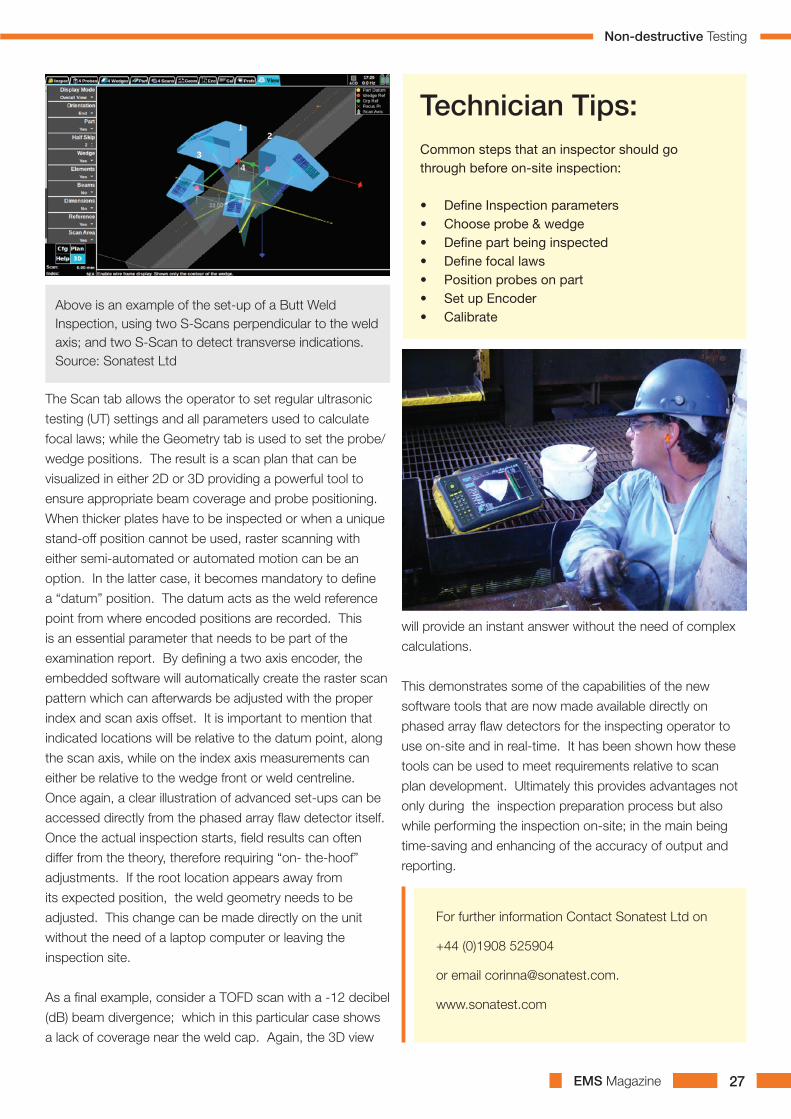
Above is an example of the set-up of a Butt Weld Inspection, using two S-Scans perpendicular to the weld axis; and two S-Scan to detect transverse indications. Source: Sonatest Ltd
The Scan tab allows the operator to set regular ultrasonic
testing (UT) settings and all parameters used to calculate
focal laws; while the Geometry tab is used to set the probe/
wedge positions. The result is a scan plan that can be
visualized in either 2D or 3D providing a powerful tool to
ensure appropriate beam coverage and probe positioning.
When thicker plates have to be inspected or when a unique
stand-off position cannot be used, raster scanning with
either semi-automated or automated motion can be an
option. In the latter case, it becomes mandatory to define
a “datum” position. The datum acts as the weld reference
point from where encoded positions are recorded. This
is an essential parameter that needs to be part of the
examination report. By defining a two axis encoder, the
embedded software will automatically create the raster scan
pattern which can afterwards be adjusted with the proper
index and scan axis offset. It is important to mention that
indicated locations will be relative to the datum point, along
the scan axis, while on the index axis measurements can
either be relative to the wedge front or weld centreline.
Once again, a clear illustration of advanced set-ups can be
accessed directly from the phased array flaw detector itself.
Once the actual inspection starts, field results can often
differ from the theory, therefore requiring “on- the-hoof”
adjustments. If the root location appears away from
its expected position, the weld geometry needs to be
adjusted. This change can be made directly on the unit
without the need of a laptop computer or leaving the
inspection site.
As a final example, consider a TOFD scan with a -12 decibel
(dB) beam divergence; which in this particular case shows
a lack of coverage near the weld cap. Again, the 3D view
will provide an instant answer without the need of complex
calculations.
This demonstrates some of the capabilities of the new
software tools that are now made available directly on
phased array flaw detectors for the inspecting operator to
use on-site and in real-time. It has been shown how these
tools can be used to meet requirements relative to scan
plan development. Ultimately this provides advantages not
only during the inspection preparation process but also
while performing the inspection on-site; in the main being
time-saving and enhancing of the accuracy of output and
reporting.
For further information Contact Sonatest Ltd on
+44 (0)1908 525904
or email [email protected].
www.sonatest.com
Non-destructive Testing
EMS Magazine28
ISO 3834 requires NDT personnel to be qualified in accordance with ISO 9712. Third-party certification is well established, and there is a choice of certification bodies accredited to ISO/IEC 17024. However, even highly reputed third-party certification may not fully address competence requirements. ISO 9001 makes the organisation responsible for determining the competences necessary for personnel performing work affecting conformity to product requirements.
For inspection bodies, UKAS has expanded upon the ISO 9001 systems approach to competence management. Its RG0 guidelines on the application of ISO/IEC 17020, state that the organization should:
A)Identify the range of inspection activitiesB) Identify the competence required for each activityC)Train and assess against the competence criteriaD)Authorise persons for activities under appropriate supervisionE)Monitor performance to re-assess competence
Third-party personnel certification may offer full compliance with stages B), C) and E), but A) and D) remain the responsibility of the inspection body. Whilst an ISO 9712 Level 2 UT operator will be competent in defect detection for the samples and applications they have experience of, that may not be the case for materials and joint geometries relevant to a new role. The competence requirements should be made explicit, for example, ‘ISO 9712 Level 2 in UT plus critical defect sizing endorsement plus two years’ experience in UT inspection of welds in C-Steel of up to 50mm thickness plus familiarity with XYZ equipment in combination with ABC probes.’ Such detailed assessments of competence requirements help with recruitment advertisements and training plans.
An effective certification body should welcome involvement from industry to ensure that their schemes address requirements. Inspection bodies and operators have utilised the TWI Certification Ltd employer-specific scheme to develop ISO 9712 compliant CSWIP certification for the specific competence assurance
requirements of their NDT procedures. Employer-specific certification is able to comply with stages A), B), C), and E) of the RG0 competence management process, and assures the full compliance of inspection and testing personnel with ISO 3834.
Additionally, with a Research and Technology Organisation, and UKAS-accredited Test House, Validation Centre and Certification Body under one roof, TWI has also provided clients with technical justification and validation of inspection procedures, verified POD, and blind trials, leading to full procedure-specific performance-based competence assurance of NDT operators. Whilst this level of competence assurance may be rarely required outside of the most highly regulated and safety critical sectors of industry, such as nuclear power, the ability to support inspection bodies with third-party certification that addresses role-specific competences is becoming increasingly necessary to satisfy compliance requirements.
Are your NDT personnel Qualified, Certified or Competent?
As ISO 3834 is being increasingly specified, it is essential that
inspection bodies involved with welded products understand its
competence requirements. ISO 3834, Quality requirements for
fusion welding of metallic materials, recognises welding as a special
process, and is the main reference for other standards, including
EN 15085, Railway applications – Welding of railway vehicles
and components, and EN 1090, Execution of steel structures and
aluminium structures, a harmonised supporting standard for the
Construction Products Regulation.
EUR ING Chris Eady CEng MRAeS
FWeldI - Chief Executive - TWI
Certification Ltd
Tel: +44(0)1223 899614
E-mail: [email protected]
Website: www.cswip.com
Non destructive Testing

EMS Magazine 29

EMS Magazine30
Recent distribution agreements mean that
customers now have a single source for all
their equipment requirements.
“The advantage of our approach is that
we can source the best products from a
selected range of different manufacturers,
whereas if you use one manufacturer for
everything you aren’t going to get the best
of each type of product, or the best price,”
said Boiswood managing partner Tony
Kent.
Buying from a single supplier also reduces
administration time and has the benefit of a
single point of contact.
Products offered by Boiswood include
valves, regulators, flow monitors, sensors
and switches, as well as general purpose
double ferrule valves and fittings. They are
available in materials such as stainless steel
and nickel alloy for general industrial use, as
well as specialty materials such as Monel
Boiswood Offers A Single Source For Process Control Equipment
Independent equipment supplier Boiswood
can offer a complete range of industrial
process control equipment. and Hastelloy for high purity applications.
Sectors served include the pharmaceutical,
petrochemical, cryogenics, water, food and
drink, HVAC, power and semiconductor
industries.
Boiswood also provides a high level of
hands-on service and support, with its
engineers working closely with customers,
including process system designers,
laboratory technicians, production
managers, chemists and other scientists.
Throughout Belzona’s history, the company has been at the forefront of addressing environmental issues through the conservation of plant and equipment and energy efficient measures in order to assist its customers with meeting their environmental goals.
Belzona can help organisations meet their environmental objectives by extending the service life of machinery and equipment, with considerable savings in energy costs when compared with refabrication.
From damaged pumps to corroded heat exchangers. By way of example, it is common for the efficiency of a worn pump to deteriorate in performance by over 10%. By rebuilding a pump with one of Belzona’s ceramic filled metal repair
products and coating with Belzona 1341 (Supermetalglide), efficiency gains of up to 20% can be achieved.
The high solar reflectance and ability to emit any collected heat has qualified Belzona 3111 (Flexible Membrane), a multi-surface waterproofing roofing membrane, to meet requirements of the US Environmental Protection Agency’s (EPA) ENERGY STAR program. In addition, as this product is water-based the product is very safe to use and produces minimal VOC’s. Belzona solutions can also act as pollution control systems. Pipes and hoses, areas of corrosion under insulation (CUI) and chemical containment areas are prone to leaks which if left untreated can result in potential environmental damage. Belzona’s cold applied solutions offer a reliable leak
repair solution, which will ensure the long term protection of buildings, structures, machinery and equipment.
By choosing Belzona’s repair, protect and improve approach, the need to replace equipment also reduces waste in terms of scrap metal and rubber. For further information on how Belzona can help you meet your environmental responsibilities please visit www.belzona.com
Belzona, Helping To Conserve The EnvironmentBelzona aims to protect the environment through both its internal controls and by the work it does to assist other organisations in meeting their environmental responsibilities.
Belzona Polymerics LimitedClaro Road, Harrogate, HG1 4DS EnglandTelephone: +44 1423 567641Facsimile: +44 1423 [email protected]
Industrial Protective Coatings
Process Control Equipment


EMS Magazine32
EMS Magazine 33
Maintenance Myths, Mindsets & MistakesPart 1 – Establishing Maintenance Task Intervals
1. Abstract
2. Introduction
3. Determining Maintenance Task Intervals
4. Failure Rate Data
5. Protective Systems
6. Conclusion
7. Further Information
This paper sets out some of the most common myths,
mindsets and mistakes that are made when establishing
maintenance task intervals.
There are four basic types of maintenance that can be
applied to equipment. The task intervals for the three
‘routine’ types of maintenance are dependent on different
factors – these factors are often poorly understood.
This lack of understanding is a common cause of poor
operational reliability and availability.
Successful reliability growth and performance improvement
is all about ‘doing the right maintenance’ on the equipment.
Determining the ‘right maintenance’ takes time and
resources.
Experience has shown that the only way to make real,
lasting improvement in the maintenance arena is by:
• Changing the way in which people think (ie dispelling
all the myths, mindsets and mistakes that have been
ingrained in maintainers’ thinking over their working life)
• Providing an approach (such as RCM [1] ) that
encompasses a structure whereby the changed thinking
can be brought to fruition.
The most common myths, mindsets and mistakes that are
made when establishing maintenance task intervals are
summarised in the following paragraphs; a full explanation is
given in the subsequent sections of this paper.
There are four basic types of maintenance that can be
applied to equipment. The task intervals for the different
types of maintenance are dependent on different factors
– these factors are often poorly understood. This lack of
understanding is a common cause of poor operational
reliability and availability.
A common statement that maintainers make is “We need to
check our critical equipment more often than our non-critical
equipment”. This sounds like good ‘common sense’ but is,
in fact, wrong for On-condition maintenance.
A common statement that maintainers make is “It doesn’t
fail so often, therefore, I don’t need to check it so often”.
This sounds like good ‘common sense’ but is wrong for
On-condition maintenance.
A common statement is “We monitor our equipment MTBFs
carefully so that we can determine how often we should
overhaul/replace equipment”. In fact the task interval (ie
the fixed interval at which the scheduled restoration or
discard task is carried out) is determined by the “life” of the
equipment. Crucially, “life” and MTBF are different.
Many maintainers think that there are just three types of
maintenance: predictive, preventive and corrective – ie
they mistakenly think that On-condition tasks (ie predictive
maintenance) and Failure-finding tasks (ie detective
maintenance) are one and the same; they are completely
different.
The belief that collecting failure rate data leads to better
maintenance is, in most instances, a myth. The data
we need is rarely available and so key decisions about
maintenance have to be made in the absence of hard data.
Organisations that rely heavily on protective systems
frequently reduce the maintenance carried out on them
in order to reduce overall spend; they assume that the
protective systems will operate when required. These
systems can and do fail; organisations may be vulnerable
to serious consequences if the protected function
subsequently fails. Maintenance spend must be directed to
where it will do the most good.
1. Abstract
Maintenance Myths
EMS Magazine34
The last 20-30 years have been characterised by massive technological change and most industries have responded by investing heavily in automation and technology to reduce headcount, improve product quality, reduce unit price and improve safety and environmental integrity etc. The net result is that organisations are increasingly reliant on their assets to perform when required.
In some organisations, equipment failure is becoming increasingly intolerable and the consequences of failure can seriously affect safety and the environment or be expensive in terms of lost production or customer service. Some failures are sufficient to threaten the financial stability of the organisation or even force it out of business.In other organisations equipment failure is much less severe but can still adversely affect profitability or customer service.
Regardless of the industry sector, organisations are striving to increase cost effectiveness – in most organisations improving equipment reliability is the key to overall performance improvement and cost effectiveness. Successful reliability growth and performance improvement is all about ‘doing the right maintenance’ on the equipment.
Many regard maintenance as ‘applied common sense [2]’ – in many respects this is true but only if the proponent of the ‘common sense’ actually understands what he or she is doing. This paper sets out some of the most common maintenance errors that many make when establishing maintenance task intervals.
The maintenance arena is littered with an assortment of myths, mindsets and mistakes which often mean that the resulting equipment maintenance does not achieve the desired outcome, is frequently flawed (sometimes fatally!) and is sometimes plain wrong.
Current management styles demand ‘instant results’ preferably via a ‘quick fix’. Frankly, it is a myth to think that quick-fixes work in the maintenance arena. Achieving reliability growth or performance improvement is neither quick nor easy; if it was, you would have done it by now!
Reliability-centred Maintenance [RCM] is an approach for determining the right maintenance for plant and equipment in its operating context. RCM is not a ‘quick fix’ but applied correctly, it can transform an organisation’s approach to maintenance and hence lead to substantial improvements in equipment reliability, overall performance and cost effectiveness.
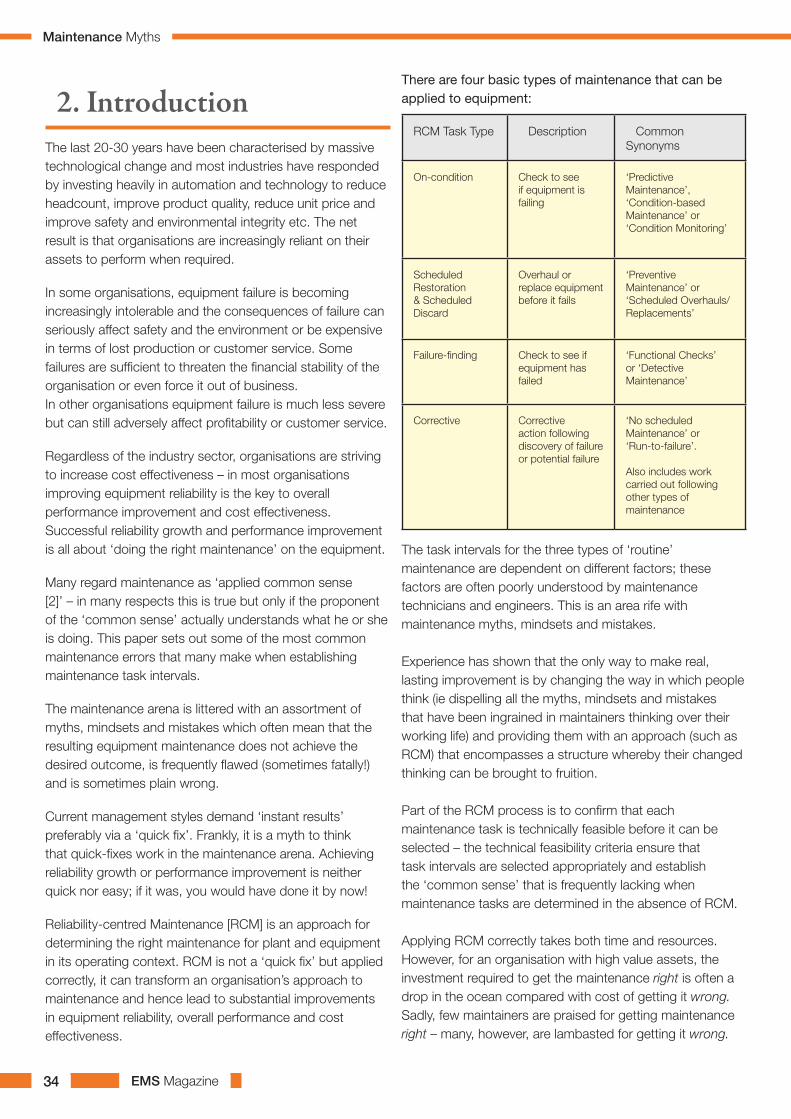
There are four basic types of maintenance that can be applied to equipment:
The task intervals for the three types of ‘routine’ maintenance are dependent on different factors; these factors are often poorly understood by maintenance technicians and engineers. This is an area rife with maintenance myths, mindsets and mistakes.
Experience has shown that the only way to make real, lasting improvement is by changing the way in which people think (ie dispelling all the myths, mindsets and mistakes that have been ingrained in maintainers thinking over their working life) and providing them with an approach (such as RCM) that encompasses a structure whereby their changed thinking can be brought to fruition.
Part of the RCM process is to confirm that each maintenance task is technically feasible before it can be selected – the technical feasibility criteria ensure that task intervals are selected appropriately and establish the ‘common sense’ that is frequently lacking when maintenance tasks are determined in the absence of RCM.
Applying RCM correctly takes both time and resources. However, for an organisation with high value assets, the investment required to get the maintenance right is often a drop in the ocean compared with cost of getting it wrong. Sadly, few maintainers are praised for getting maintenance right – many, however, are lambasted for getting it wrong.
RCM Task Type Description Common Synonyms
On-condition Check to see if equipment is failing
‘Predictive Maintenance’, ‘Condition-based Maintenance’ or ‘Condition Monitoring’
Scheduled Restoration & Scheduled Discard
Overhaul or replace equipment before it fails
‘Preventive Maintenance’ or ‘Scheduled Overhauls/Replacements’
Failure-finding Check to see if equipment has failed
‘Functional Checks’ or ‘Detective Maintenance’
Corrective Corrective action following discovery of failure or potential failure
‘No scheduled Maintenance’ or ‘Run-to-failure’.
Also includes work carried out following other types of maintenance
2. Introduction
Maintenance Myths

EMS Magazine 35
EMS Magazine36
Mistakes in determining maintenance task intervals are common (usually because the factors that determine the task intervals for the different types of maintenance are poorly understood).
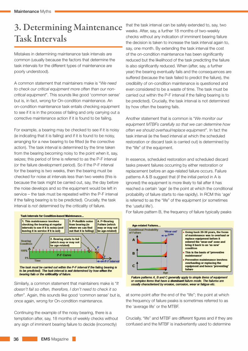
A common statement that maintainers make is “We need to check our critical equipment more often than our non-critical equipment”. This sounds like good ‘common sense’ but is, in fact, wrong for On-condition maintenance. An on-condition maintenance task entails checking equipment to see if it is in the process of failing and only carrying out a corrective maintenance action if it is found to be failing.
For example, a bearing may be checked to see if it is noisy (ie indicating that it is failing) and if it is found to be noisy, arranging for a new bearing to be fitted (ie the corrective action). The task interval is determined by the time taken from the bearing becoming noisy to the point when it, say, seizes; this period of time is referred to as the P-F interval (or the failure development period). So if the P-F interval for the bearing is two weeks, then the bearing must be checked for noise at intervals less than two weeks (this is because the task might be carried out, say, the day before the noise develops and so the equipment would be left in service – the task must be repeated within the P-F interval if the failing bearing is to be predicted). Crucially, the task interval is not determined by the criticality of failure.
Similarly, a common statement that maintainers make is “It doesn’t fail so often, therefore, I don’t need to check it so often”. Again, this sounds like good ‘common sense’ but is, once again, wrong for On-condition maintenance.
Continuing the example of the noisy bearing, there is a temptation after, say, 18 months of weekly checks without any sign of imminent bearing failure to decide (incorrectly)
3. Determining Maintenance Task Intervals
that the task interval can be safely extended to, say, two weeks. After, say, a further 18 months of two-weekly checks without any indication of imminent bearing failure the decision is taken to increase the task interval again to, say, one month. By extending the task interval the cost of the on-condition maintenance has been significantly reduced but the likelihood of the task predicting the failure is also significantly reduced. When (after, say, a further year) the bearing eventually fails and the consequences are suffered (because the task failed to predict the failure), the credibility of on-condition maintenance is questioned and even considered to be a waste of time. The task must be carried out within the P-F interval if the failing bearing is to be predicted). Crucially, the task interval is not determined by how often the bearing fails.
Another statement that is common is “We monitor our equipment MTBFs carefully so that we can determine how often we should overhaul/replace equipment”. In fact the task interval (ie the fixed interval at which the scheduled restoration or discard task is carried out) is determined by the “life” of the equipment.
In essence, scheduled restoration and scheduled discard tasks prevent failures occurring by either restoration or replacement before an age-related failure occurs. Failure patterns A & B suggest that (if the initial period in A is ignored) the equipment is more likely to fail after it has reached a certain ‘age’ (ie the point at which the conditional probability of failure starts to rise rapidly). In RCM this ‘age’ is referred to as the “life” of the equipment (or sometimes the ‘useful life’).For failure pattern B, the frequency of failure typically peaks
at some point after the end of the “life”; the point at which the frequency of failure peaks is sometimes referred to as the ‘average life’ or the MTBF.
Crucially, “life” and MTBF are different figures and if they are confused and the MTBF is inadvertently used to determine
Maintenance Myths

EMS Magazine 37
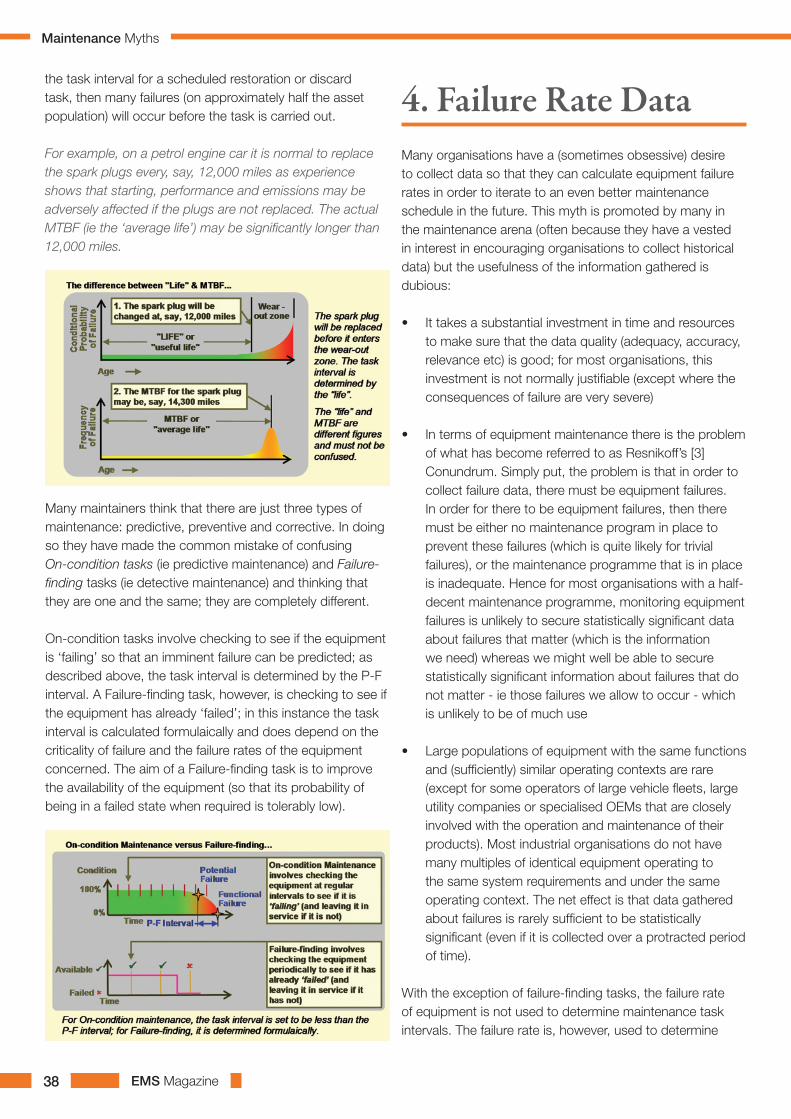
EMS Magazine38
the task interval for a scheduled restoration or discard task, then many failures (on approximately half the asset population) will occur before the task is carried out.
For example, on a petrol engine car it is normal to replace the spark plugs every, say, 12,000 miles as experience shows that starting, performance and emissions may be adversely affected if the plugs are not replaced. The actual MTBF (ie the ‘average life’) may be significantly longer than 12,000 miles.
Many maintainers think that there are just three types of maintenance: predictive, preventive and corrective. In doing so they have made the common mistake of confusing On-condition tasks (ie predictive maintenance) and Failure-finding tasks (ie detective maintenance) and thinking that they are one and the same; they are completely different.
On-condition tasks involve checking to see if the equipment is ‘failing’ so that an imminent failure can be predicted; as described above, the task interval is determined by the P-F interval. A Failure-finding task, however, is checking to see if the equipment has already ‘failed’; in this instance the task interval is calculated formulaically and does depend on the criticality of failure and the failure rates of the equipment concerned. The aim of a Failure-finding task is to improve the availability of the equipment (so that its probability of being in a failed state when required is tolerably low).
Many organisations have a (sometimes obsessive) desire to collect data so that they can calculate equipment failure rates in order to iterate to an even better maintenance schedule in the future. This myth is promoted by many in the maintenance arena (often because they have a vested in interest in encouraging organisations to collect historical data) but the usefulness of the information gathered is dubious:
• It takes a substantial investment in time and resources to make sure that the data quality (adequacy, accuracy, relevance etc) is good; for most organisations, this investment is not normally justifiable (except where the consequences of failure are very severe)
• In terms of equipment maintenance there is the problem of what has become referred to as Resnikoff’s [3] Conundrum. Simply put, the problem is that in order to collect failure data, there must be equipment failures. In order for there to be equipment failures, then there must be either no maintenance program in place to prevent these failures (which is quite likely for trivial failures), or the maintenance programme that is in place is inadequate. Hence for most organisations with a half-decent maintenance programme, monitoring equipment failures is unlikely to secure statistically significant data about failures that matter (which is the information we need) whereas we might well be able to secure statistically significant information about failures that do not matter - ie those failures we allow to occur - which is unlikely to be of much use
• Large populations of equipment with the same functions and (sufficiently) similar operating contexts are rare (except for some operators of large vehicle fleets, large utility companies or specialised OEMs that are closely involved with the operation and maintenance of their products). Most industrial organisations do not have many multiples of identical equipment operating to the same system requirements and under the same operating context. The net effect is that data gathered about failures is rarely sufficient to be statistically significant (even if it is collected over a protracted period of time).
With the exception of failure-finding tasks, the failure rate of equipment is not used to determine maintenance task intervals. The failure rate is, however, used to determine
4. Failure Rate Data
Maintenance Myths

EMS Magazine 39
whether or not maintenance is worth doing and in
determining spare parts stocking policy.
In summary, therefore, the belief that collecting failure rate
data leads to better maintenance is, in most instances,
a myth. In practice serious decisions about maintenance
have to be made with inadequate hard data simply because
the data that we need is rarely available. RCM provides
a framework to highlight what information is needed and
a structure to enable RCM Analysis groups to make the
necessary decisions about maintenance task intervals (in
particular) in the absence of hard data.
In modern, high risk process plant it is not uncommon for
the maintenance of the protective systems to account for
more than 30% of the maintenance labour spend on site;
the reason for this is simply the number of these systems
that have been installed (and need on-going maintenance).
Organisations that rely heavily on protective systems
frequently make the mistake of assuming that their
protective systems will act when required (ie if the protected
function fails) and reduce the maintenance carried out on
the protective systems to save money. However, protective
systems can and do fail.
Over the years, the introduction of technology solutions
and automation into many organisations was primarily
focused on reducing product unit cost (largely by increasing
throughput and reducing headcount - particularly production
personnel). This transition has been successful in many
industries and most organisations now rely very heavily on
5. Protective Systems
the installed technology and automation.
In addition to reducing product unit costs, the wide-scale
application of technology and automation has done much to
improve safety and environmental integrity. Many high-risk
industries are very reliant on automation to ensure safety
and environmental integrity - the risk of major incidents
occurring has been reduced substantially by the introduction
of protective systems (which are often configured in ‘layers’
so that failure of any one protective system is protected by
another protective system etc).
The large population of protective systems installed and
the level of protection provided does come with a risk -
complacency on behalf of the maintainers (which is further
compounded when organisation are under financial pressure
to reduce spend). Automation in general and protective
systems in particular can and do fail; some modern control
systems are designed to identify and sound an alarm if there
is a failure in the protection system but many do not. In
practice, organisations may well be unaware that protective
systems are in a failed state which, in turn, makes them very
vulnerable to serious consequences if the protected function
subsequently fails.
There have been some significant headline industrial
accidents that have occurred because protective systems
have been in a failed state when called upon to operate;
several of these incidents have been as a direct result of
complacency with regard to protective systems and some
have been attributable to maintenance cost-cutting.
RCM allows organisations to determine the maintenance
requirements of the protective systems so that the
combined probability of the system being in a failed state
when the protected function subsequently fails is reduced
to a tolerable level. This ensures that maintenance spend is
directed to where it will do the most good.
Maintenance Myths

EMS Magazine40
The drive to improve cost effectiveness has led
organisations to focus on increasing equipment
reliability so as to improve overall performance (and
hence cost effectiveness). Successful reliability growth
and performance improvement is all about ‘doing the
right maintenance on the equipment’. There is a great
temptation to improve cost effectiveness by reducing
maintenance budgets – this works in the very short
term but not in the medium and longer terms.
The maintenance arena is littered with an assortment
of myths, mindsets and mistakes which often mean
that the resulting equipment maintenance does not
achieve the desired outcome, is frequently flawed and
is sometimes plain wrong. In particular, it is a myth
to think that quick-fixes work in the maintenance
arena. Achieving reliability growth or performance
improvement is neither quick nor easy; if it was, you
would have done it by now!
Reliability-centred Maintenance [RCM] is a proven
approach for determining the right maintenance for
plant and equipment in its operating context. With its
beginnings in the demanding civil aviation industry,
RCM is not a ‘quick fix’ but applied correctly, it can
transform an organisation’s approach to maintenance
and hence lead to substantial improvements in
equipment reliability, overall performance and cost
effectiveness. RCM optimises the maintenance for the
on-site equipment and in so doing ensures that money
spent on maintenance is spent where it will do the
most good.
Applying RCM correctly takes both time and
resources. However, for an organisation with high
value assets, the investment required to get the
maintenance right is often a drop in the ocean
compared with cost of getting it wrong. In brief, the
return on investment for RCM is substantial provided
that the assorted maintenance myths, mindsets and
mistakes are dispelled and the right maintenance is
implemented.
6. Conclusion;
This paper was written by Simon Deakin and Steve Bailey of Mutual Consultants Ltd. See also Maintenance Myths, Mindsets and Mistakes Parts 2 & 3, Improving Operational Reliability & Availability and The Maintenance Arena respectively.
Please do not hesitate to contact either of us for more information on how RCM can transform equipment performance and achieve desired operational reliability and availability:
[1] RCM – Reliability-centred Maintenance. Short-form definition: “A process used to determine the maintenance requirements of plant and equipment in its operating context”
[2] A dictionary definition of ‘common sense’ is: sound practical judgment that is independent of specialised knowledge, training, or the like; normal native intelligence.
[3] HL Resnikoff, Mathematical Aspects of Reliability-centered Maintenance, 1978
Simon Deakin is the Managing Director of Mutual Consultants Limited and a mechanical engineer.
He has extensive practical experience and training skills in RCM which have been developed over a period of more than twenty years working with both large and small clients in diverse industries. Simon is an experienced RCM practitioner fully trained by Aladon LLC.
Prior to working in consulting he worked in the design, installation and commissioning of major capital equipment to the process and manufacturing industries.
Steve Bailey is a Senior Consultant and a mechanical engineer.
He has over 14 years of practical experience and training skills in RCM preceded by seventeen years of railway experience at a number of maintenance depots both in a technical and managerial capacity. Steve is an experienced RCM practitioner fully trained by Aladon LLC.
Steve is also trained in Commercial Systems Analysis, Software Engineering and Simulation Modelling and has developed many bespoke software applications.
7. Further Information;
Maintenance Myths

EMS Magazine42
With today’s optimized machinery, alignment is a vital part in the daily Maintenance work. Machines need to be online continuously with a minimum of interruptions. A machine breakdown causes devastating loss of production.
“Nearly 50% of all machine
breakdowns are caused by
misalignment”
Monition Ltd has created a dedicated website to promote awareness and knowledge for all alignment applications. This includes the supply of Fixturlaser products to help compete in today’s marketplace. The products are designed to help outperform your competitors regarding price, quality and reliability. Keeping your machines in line and online are all crucial factors in order to stay ahead of the competition. We welcome you
Alignment Of Machines Has Been Performed For Over 200 Years
The reasons have not always been obvious, but in the modern world the necessity of alignment is common knowledge.
to explore what www.shaftalignment.co.uk can do for your business!
Laser Alignment for Everyone www.shaftalignment.co.uk
For additional information
telephone Monition on:
01909 722000
Alternatively you can email us
at: [email protected].
From the simple one-button-to-press, VibMeter 320 to top-of-the-range units for condition based and predictive maintenance, machine balancing and alignment, C-Cubed’s products are all incredibly easy to use. C-Cubed’s new Vib Meter 320is a simple to use,incredibly low cost vibration meter that records, analyses and displays vibration signals at the push of a button. The unit includes colour coded alarmlevels for ISO values and bearing condition,zoomablevibration spectrum (FFT) with cursor anddiagnosesout of balance, misalignment and looseness.
The Vib Meter 320 represents the very latest in technology with an 800 lines resolution FFT, fully zoomable, vibration spectrum display. The fully dymanic cursor displays frequency and amplitude values and readings can be saved and recalled at will. Colour coded frequency band alarms based on run speed can be displayed to diagnose machine faults with all alarm levels and settings stored in non-volatile flash memory. The Vib Meter 320 is the latest in a line ofeasy to use high specification maintenance products and perfectly complements C-Cubed’s family of condition based monitoring and
inspection systems, offering high level functionality and capability at extremely low cost. The Vib Meter 320 can be fully customised for private label versions and is available with quantity discounts for OEM applications.
Vibration Analysis Tools For Maintenance Engineers.C-Cubed manufactures and supplies a complete range of low cost, high performance, easy to use vibration analysis tools for maintenance engineers.
C-Cubed +44 (0) 1256 [email protected]
Vibration Analysis
Machine Alignment
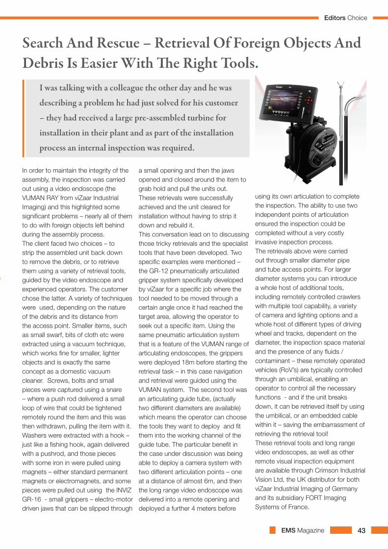
EMS Magazine 43
In order to maintain the integrity of the assembly, the inspection was carried out using a video endoscope (the VUMAN RAY from viZaar Industrial Imaging) and this highlighted some significant problems – nearly all of them to do with foreign objects left behind during the assembly process. The client faced two choices – to strip the assembled unit back down to remove the debris, or to retrieve them using a variety of retrieval tools, guided by the video endoscope and experienced operators. The customer chose the latter. A variety of techniques were used, depending on the nature of the debris and its distance from the access point. Smaller items, such as small swarf, bits of cloth etc were extracted using a vacuum technique, which works fine for smaller, lighter objects and is exactly the same concept as a domestic vacuum cleaner. Screws, bolts and small pieces were captured using a snare – where a push rod delivered a small loop of wire that could be tightened remotely round the item and this was then withdrawn, pulling the item with it. Washers were extracted with a hook – just like a fishing hook, again delivered with a pushrod, and those pieces with some iron in were pulled using magnets – either standard permanent magnets or electromagnets, and some pieces were pulled out using the INVIZ GR-16 - small grippers – electro-motor driven jaws that can be slipped through
a small opening and then the jaws opened and closed around the item to grab hold and pull the units out. These retrievals were successfully achieved and the unit cleared for installation without having to strip it down and rebuild it. This conversation lead on to discussing those tricky retrievals and the specialist tools that have been developed. Two specific examples were mentioned – the GR-12 pneumatically articulated gripper system specifically developed by viZaar for a specific job where the tool needed to be moved through a certain angle once it had reached the target area, allowing the operator to seek out a specific item. Using the same pneumatic articulation system that is a feature of the VUMAN range of articulating endoscopes, the grippers were deployed 18m before starting the retrieval task – in this case navigation and retrieval were guided using the VUMAN system. The second tool was an articulating guide tube, (actually two different diameters are available) which means the operator can choose the tools they want to deploy and fit them into the working channel of the guide tube. The particular benefit in the case under discussion was being able to deploy a camera system with two different articulation points – one at a distance of almost 6m, and then the long range video endoscope was delivered into a remote opening and deployed a further 4 meters before
using its own articulation to complete the inspection. The ability to use two independent points of articulation ensured the inspection could be completed without a very costly invasive inspection process.The retrievals above were carried out through smaller diameter pipe and tube access points. For larger diameter systems you can introduce a whole host of additional tools, including remotely controlled crawlers with multiple tool capability, a variety of camera and lighting options and a whole host of different types of driving wheel and tracks, dependent on the diameter, the inspection space material and the presence of any fluids / contaminant – these remotely operated vehicles (RoV’s) are typically controlled through an umbilical, enabling an operator to control all the necessary functions - and if the unit breaks down, it can be retrieved itself by using the umbilical, or an embedded cable within it – saving the embarrassment of retrieving the retrieval tool!These retrieval tools and long range video endoscopes, as well as other remote visual inspection equipment are available through Crimson Industrial Vision Ltd, the UK distributor for both viZaar Industrial Imaging of Germany and its subsidiary FORT Imaging Systems of France.
Search And Rescue – Retrieval Of Foreign Objects And Debris Is Easier With The Right Tools.
I was talking with a colleague the other day and he was
describing a problem he had just solved for his customer
– they had received a large pre-assembled turbine for
installation in their plant and as part of the installation
process an internal inspection was required.
Editors Choice
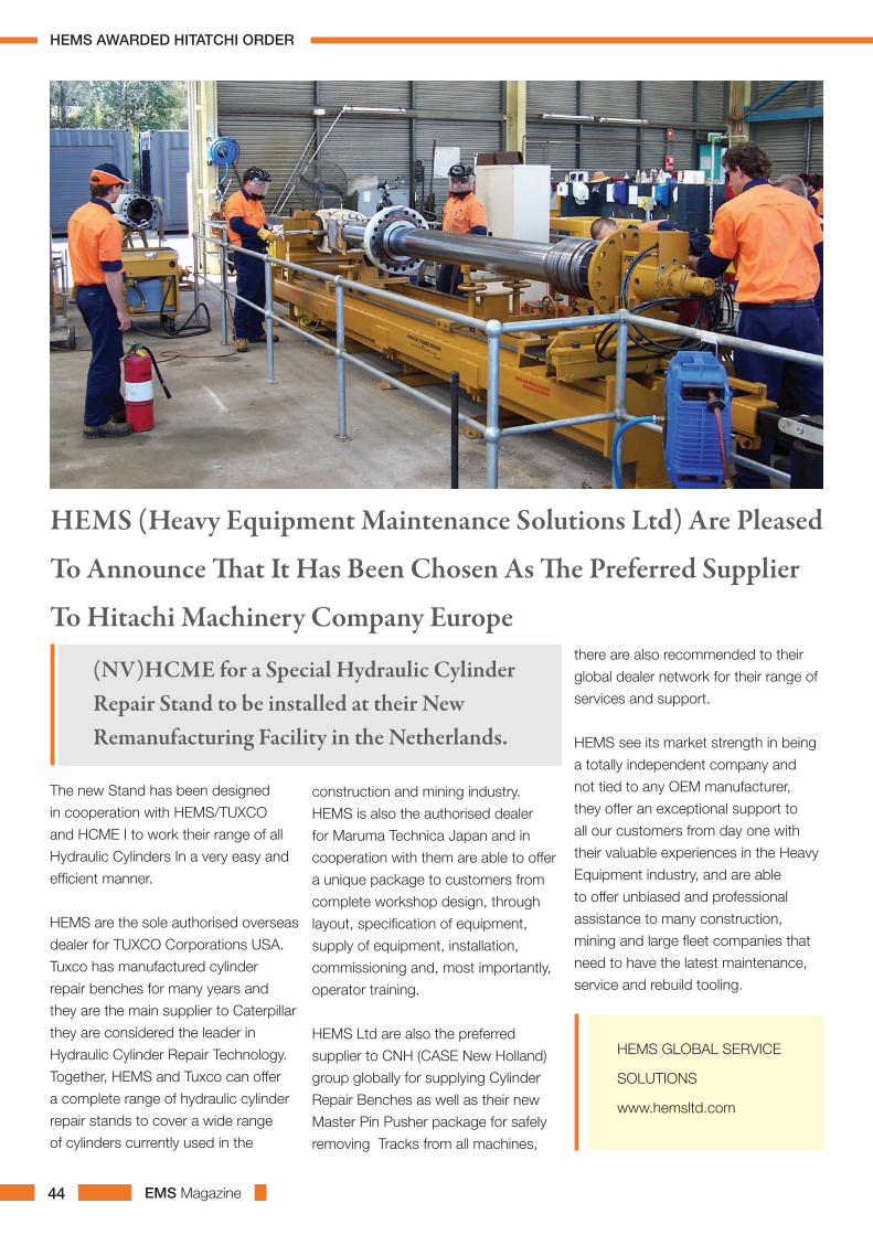
EMS Magazine44
The new Stand has been designed
in cooperation with HEMS/TUXCO
and HCME I to work their range of all
Hydraulic Cylinders In a very easy and
efficient manner.
HEMS are the sole authorised overseas
dealer for TUXCO Corporations USA.
Tuxco has manufactured cylinder
repair benches for many years and
they are the main supplier to Caterpillar
they are considered the leader in
Hydraulic Cylinder Repair Technology.
Together, HEMS and Tuxco can offer
a complete range of hydraulic cylinder
repair stands to cover a wide range
of cylinders currently used in the
construction and mining industry.
HEMS is also the authorised dealer
for Maruma Technica Japan and in
cooperation with them are able to offer
a unique package to customers from
complete workshop design, through
layout, specification of equipment,
supply of equipment, installation,
commissioning and, most importantly,
operator training.
HEMS Ltd are also the preferred
supplier to CNH (CASE New Holland)
group globally for supplying Cylinder
Repair Benches as well as their new
Master Pin Pusher package for safely
removing Tracks from all machines,
HEMS (Heavy Equipment Maintenance Solutions Ltd) Are Pleased
To Announce That It Has Been Chosen As The Preferred Supplier
To Hitachi Machinery Company Europe there are also recommended to their
global dealer network for their range of
services and support.
HEMS see its market strength in being
a totally independent company and
not tied to any OEM manufacturer,
they offer an exceptional support to
all our customers from day one with
their valuable experiences in the Heavy
Equipment industry, and are able
to offer unbiased and professional
assistance to many construction,
mining and large fleet companies that
need to have the latest maintenance,
service and rebuild tooling.
(NV)HCME for a Special Hydraulic Cylinder Repair Stand to be installed at their New Remanufacturing Facility in the Netherlands.
HEMS GLOBAL SERVICE
SOLUTIONS
www.hemsltd.com
HEMS AWARDED HITATCHI ORDER

EMS Magazine 45
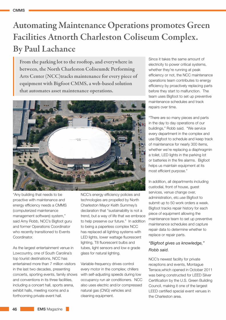
EMS Magazine46
“Any building that needs to be proactive with maintenance and energy efficiency needs a CMMS (computerized maintenance management software) system,” said Amy Robb, NCC’s Bigfoot guru and former Operations Coordinator who recently transitioned to Events Coordinator.
As the largest entertainment venue in Lowcountry, one of South Carolina’s top tourist destinations, NCC has entertained more than 7 million visitors in the last two decades, presenting concerts, sporting events, family shows and conventions in its three facilities, including a concert hall, sports arena, exhibit halls, meeting rooms and a forthcoming private event hall.
NCC’s energy efficiency policies and technologies are propelled by North Charleston Mayor Keith Summey’s declaration that “sustainability is not a trend, but a way of life that we embrace to help preserve our future.” In addition to being a paperless complex NCC has replaced all lighting systems with LED lights, lower wattage fluorescent lighting, T8 fluorescent bulbs and tubes, light sensors and low e grade glass for natural lighting.
Variable-frequency drives control every motor in the complex; chillers with self-adjusting speeds during low occupancy run air conditioners. NCC also uses electric and/or compressed natural gas (CNG) vehicles and cleaning equipment.
Since it takes the same amount of electricity to power critical systems, whether they’re running at peak efficiency or not, the NCC maintenance operations team contributes to energy efficiency by proactively replacing parts before they start to malfunction. The team uses Bigfoot to set up preventive maintenance schedules and track repairs over time.
“There are so many pieces and parts in the day to day operations of our buildings,” Robb said. “We service every department in the complex and use Bigfoot to schedule and keep track of maintenance for nearly 300 items, whether we’re replacing a diaphragmin a toilet, LED lights in the parking lot or batteries in the fire alarms. Bigfoot helps us maintain equipment at its most efficient purpose.”
In addition, all departments including custodial, front of house, guest services, venue change over, administration, etc.use Bigfoot to submit up to 50 work orders a week. Bigfoot tracks repair history for each piece of equipment allowing the maintenance team to set up preventive maintenance schedules and capture repair data to determine whether to replace or repair parts.
“Bigfoot gives us knowledge,”
Robb said.
NCC’s newest facility for private receptions and events, Montague Terrace,which opened in October 2011 was being constructed for LEED Silver Certification by the U.S. Green Building Council, making it one of the largest LEED certified special event venues in the Charleston area.
Automating Maintenance Operations promotes Green Facilities Atnorth Charleston Coliseum Complex.By Paul Lachance
From the parking lot to the rooftop, and everywhere in between, the North Charleston Coliseum& Performing Arts Center (NCC)tracks maintenance for every piece of equipment with Bigfoot CMMS, a web-based solution that automates asset maintenance operations.
CMMS

EMS Magazine 47
“Bigfoot will definitely help us get LEED certified by tracking equipment and building a maintenance forecasting systemfor the new facility,” Robb said. “We are already setting up future PM schedules with three-week lead times for maintenance checks. So Bigfoot alerts us if we need to replace an air filter or a lobby door, or plan for more maintenance resources.”
CMMS for Sustainability, Energy and Utility Optimization
A well-developed CMMS software package designed by software developers who take the time to understand the needs of facilities maintenance and operations professionals, can be a fundamental contributor to energy efficiency and support of green practices.
Energy costs are one of the biggest line items in an organization’s budget. Given the financial impact this can have it is little wonder that many facilities managers and energy engineers are on a mission to trim costs wherever possible. Installing alternative energy systems doesn’t necessarily equal energy efficiency unless the equipment is being monitored and necessary action taken when it is found to be operating at less than peak efficiency.
CMMS monitors a variety of meter readings, including pressure, temperature, voltage and hours run, and also helps operators identify energy peaks and spikes. Thorough preventive maintenance (PM) planning can dramatically improve the energy efficiency of facility assets.
CMMS should interface with commercially available technologies to correlate energy consumption with specific asset performance levels to identify “energy hogs.” Then PMs can be set up based on hourly run times instead of extended calendar periods,
ensuring they are completed at optimal times. This results in a more efficient use of staff, reduced downtime and lower maintenance costs.
Tracking and monitoring an asset’s utility consumption can also help trigger appropriate corrective and preventive action. For example, if an asset is “running hot,” based on thermal readings or spikes in utility consumption, this might indicate a potential maintenance issue. CMMS can capture warnings, chart a trend and trigger a PM. The result is optimal equipment operation without relying on manual monitoring, and reduced energy consumption, which translates to increased profitability.
Improved EfficiencyInterfacing CMMS with building automation systems allows operators to capture alarm data, display trends and automatically trigger work orders. For example, an overheated air handler generates an alarm ticket, which creates a work order. The cause is diagnosed as an electrical issue. With the help of CMMS, the maintenance team is able to correct the issue and now the unit requires less energy to operate. Over time, operators can observe energy spikes on a particular air handler unit and become proactive about scheduling work orders for those peak periods.
For facility maintenance, strong asset utilization can equate to less asset
usage and less energy consumption. For example, if an HVAC system is operating efficiently because of comprehensive PM work managed by CMMS, facilities managers use less heating from boiler X, when boiler Y and Z are running efficiently.
CMMS can also track equipment history and grade performance over time. Instead of automatically projecting capital expenses to replace old equipment, CMMS identifies which assets are poor performers by ranking every component. Surprisingly, a newer asset could be consuming more energy by failing frequently and costing more to repair over time. An asset would be retired or replaced based on several factors besides its age: frequency of failure, energy consumption, frequency of work orders, cost trends, etc. Using CMMS a facilities manager can be proactive about his maintenance plan and reduce capital expenditures.
For a manufacturer, finely
tuned operation of production
equipment creates more output
with less waste, and less waste
equals fewer raw materials used.
Improved utilization and reduced
downtime equals less energy
consumption, lower costs and
sustainable operations. CMMS
automates the preventative
maintenance plan for all plant
floor equipment.
CMMS
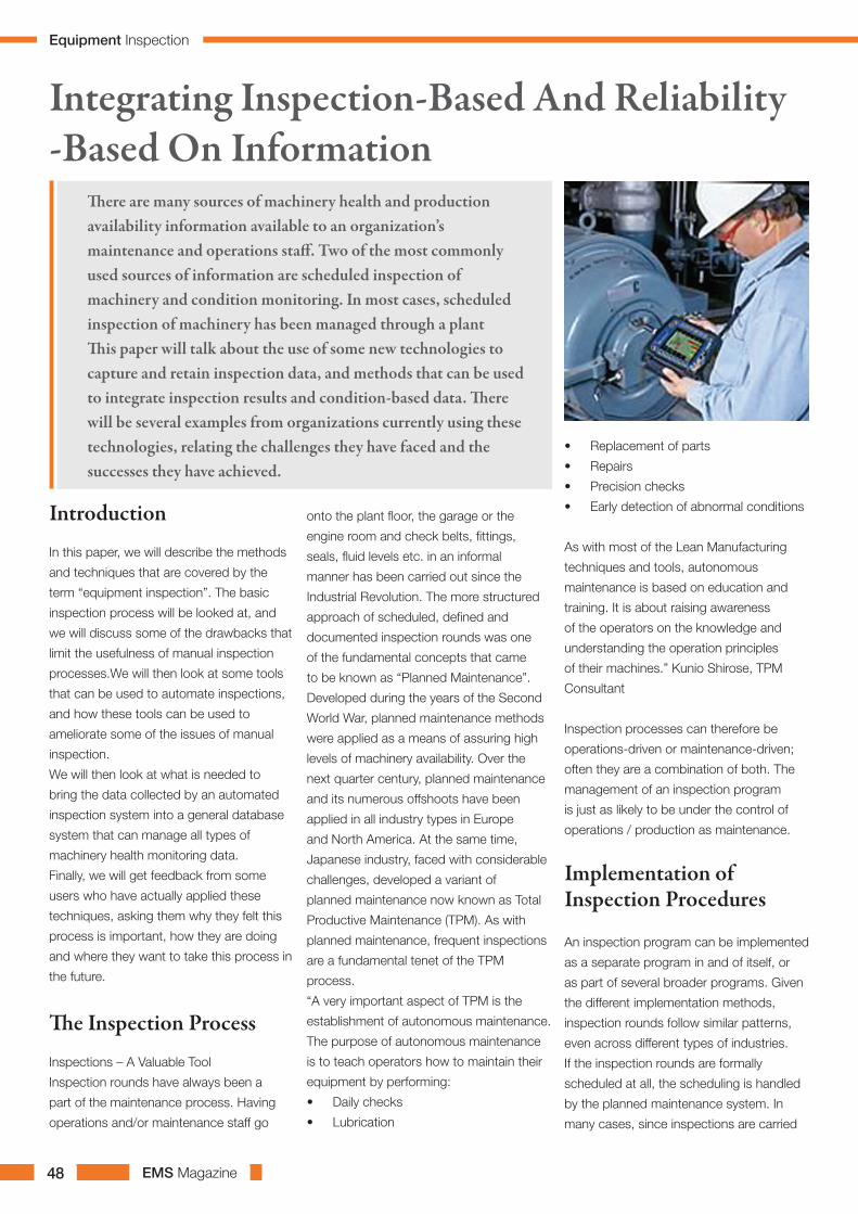
EMS Magazine48
Introduction
In this paper, we will describe the methods
and techniques that are covered by the
term “equipment inspection”. The basic
inspection process will be looked at, and
we will discuss some of the drawbacks that
limit the usefulness of manual inspection
processes.We will then look at some tools
that can be used to automate inspections,
and how these tools can be used to
ameliorate some of the issues of manual
inspection.
We will then look at what is needed to
bring the data collected by an automated
inspection system into a general database
system that can manage all types of
machinery health monitoring data.
Finally, we will get feedback from some
users who have actually applied these
techniques, asking them why they felt this
process is important, how they are doing
and where they want to take this process in
the future.
The Inspection Process
Inspections – A Valuable Tool
Inspection rounds have always been a
part of the maintenance process. Having
operations and/or maintenance staff go
onto the plant floor, the garage or the
engine room and check belts, fittings,
seals, fluid levels etc. in an informal
manner has been carried out since the
Industrial Revolution. The more structured
approach of scheduled, defined and
documented inspection rounds was one
of the fundamental concepts that came
to be known as “Planned Maintenance”.
Developed during the years of the Second
World War, planned maintenance methods
were applied as a means of assuring high
levels of machinery availability. Over the
next quarter century, planned maintenance
and its numerous offshoots have been
applied in all industry types in Europe
and North America. At the same time,
Japanese industry, faced with considerable
challenges, developed a variant of
planned maintenance now known as Total
Productive Maintenance (TPM). As with
planned maintenance, frequent inspections
are a fundamental tenet of the TPM
process.
“A very important aspect of TPM is the
establishment of autonomous maintenance.
The purpose of autonomous maintenance
is to teach operators how to maintain their
equipment by performing:
• Daily checks
• Lubrication
• Replacement of parts
• Repairs
• Precision checks
• Early detection of abnormal conditions
As with most of the Lean Manufacturing
techniques and tools, autonomous
maintenance is based on education and
training. It is about raising awareness
of the operators on the knowledge and
understanding the operation principles
of their machines.” Kunio Shirose, TPM
Consultant
Inspection processes can therefore be
operations-driven or maintenance-driven;
often they are a combination of both. The
management of an inspection program
is just as likely to be under the control of
operations / production as maintenance.
Implementation of Inspection Procedures
An inspection program can be implemented
as a separate program in and of itself, or
as part of several broader programs. Given
the different implementation methods,
inspection rounds follow similar patterns,
even across different types of industries.
If the inspection rounds are formally
scheduled at all, the scheduling is handled
by the planned maintenance system. In
many cases, since inspections are carried
Integrating Inspection-Based And Reliability -Based On Information
There are many sources of machinery health and production availability information available to an organization’s maintenance and operations staff. Two of the most commonly used sources of information are scheduled inspection of machinery and condition monitoring. In most cases, scheduled inspection of machinery has been managed through a plant This paper will talk about the use of some new technologies to capture and retain inspection data, and methods that can be used to integrate inspection results and condition-based data. There will be several examples from organizations currently using these technologies, relating the challenges they have faced and the successes they have achieved.
Equipment Inspection
EMS Magazine 49
out on a daily or per shift basis, they are not
scheduled as work orders; they are treated
as part of the daily routine. Sometimes
inspection results are entered back into the
maintenance system (CMMS), but this is
unusual – in most cases they are not.
Traditional inspection data collection
tools are clipboards and check sheets. A
series of check sheets are created for the
inspector to follow. They can range from
very informal (“if you see a problem, make a
note on this form”) to very specific (“Check
Sheet PMP-1A is specifically tailored for
motor driven pumps in the finishing room.
Please complete all sections. Use an X
in the check boxes, not a tick mark.”)
Typically, the only review mechanism
available to determine if the work is being
done is to read/review the check sheets.
In some programs, results are keyed into
programs like Excel / Access etc. This
requires either 1) clerical staff support, or
2) the use of maintenance / operations
personnel to enter the data. These efforts
are often subject to interruption or even
abandonment if clerical support becomes
unavailable or if the inspection sheet data
entry becomes too heavily backlogged.
Challenges to Inspection Procedures
There are a number of challenges to the
manual inspection process. Inspection
programs using check sheets are difficult to
monitor – many inspection rounds never get
carried out, and it’s difficult to determine if
they haven’t been carried out.
The data collected on inspection check
sheets is highly prone to error – entries
are illegible, different inspectors use their
own terms to describe problem conditions,
meter values are transcribed incorrectly.
This is difficult for the person reviewing the
inspection results, and even more difficult if
those results are required to be entered into
a database or a spreadsheet.
Another source of error is simply that there
is often confusion about which machine
train is being inspected – especially in
process industries where there is lots of
identical equipment in operation.
The inspection check sheet offers little
additional support to the inspector when
he/she discovers what may be a problem
– there isn’t any way to review previous
inspections or query the check sheet for
further help.
Finally, the inspection check sheets need to
be reviewed by someone capable of taking
the next step – either ordering work to be
done or more tests.
Automated Inspection Methods
Even with the substantial challenges
presented by manual inspection methods,
the results are highly beneficial. Plants that
have implemented these programs report
substantial returns on investment and
increased asset availability. The benefits of a
properly managed inspection program have
led to the adoption of new technology to
reduce or eliminate some of the difficulties
of paper-based inspections.
What is automated inspection?
Automated inspection involves the use of
portable instrumentation to electronically
capture the inspection results at the
machine itself.
Inspection rounds, instead of being printed
out as check sheets or work orders are
downloaded to handheld computers, just
like routes are downloaded to a vibration
data collector. Instead of carrying a
clipboard from machine to machine, the
operator carries the handheld computer,
entering observational and meter data into
the computer.
The operator can either follow the machine
order set in the handheld computer (walk
the round) or the operator can choose to
follow his own route, and use a bar code,
touch button or RFID (radio frequency
identification) scanner to identify the
machine that is being inspected.
If the operator wants to make a note, he/
she is able to use the pen and/or the
keyboard to enter a note directly into the
handheld computer.
Once the round is completed, the data is
uploaded into a workstation (once again,
just like uploading a vibration route).
The operator is able to produce reports,
generate alarms etc. At least one system
exists that allow the automatic generation
of corrective work orders based on the data
collected in the inspection rounds.
Automation HardwareUntil recently, clipboards and forms were
the only really effective tool that could be
applied to basic machinery inspection.
Commercial–grade laptop computers are
too fragile to be taken out onto the shop
floor. Devices designed for other types of
data collection, such as vibration analysis,
are rugged enough to be taken into the
plant, but they are too expensive to be
broadly deployed to operators, and they
are not flexible enough to collect the data
sets needed for effective inspection. In the
last three years, a new type of device, the
industrial handheld computer, has been
applied to the inspection process. These
units combine the ease of use of consumer
grade PDA’s such as the Palm and the
Pocket PC with the ruggedness of industrial
instrumentation. They are generally
equipped with touch screens and pens, like
the consumer PDA’s. Some units also come
equipped with keyboards.
The industrial handheld marketplace is
relatively new, and highly competitive. As
such, handheld computer hardware has
been the focus of considerable research
and development, with the happy benefit
(for the users of this technology) that the
price / performance ratio of these units
has dropped considerably since their
introduction.
Advantages of automation
Direct Data Capture
All data is captured at source, minimizing
the possibility of error and eliminating the
need for keypunching.
Using pre-defined pick lists (Figure 3) and
comments ensures consistency of data
Equipment Inspection

EMS Magazine50
throughout the plant, improving the ability to
use inspection data as a decision support
tool.
Proper Machine Identification
Industrial handheld devices can use
integrated bar coding or other identification
tags (RFID, touch button, etc.) to ensure
that the operator is collecting data about
the right machine.
Improves Field-Level Decision Making
The operator can have alarms, historical
trends, on-alert instructions and machine
schematics downloaded into the handheld
device or available through a wireless link.
This allows the operator to receive further
instructions in the event of an alarm while
he is at the machine.
Automatic Escalation of Detected Problems
Manual inspection methods require
someone (either the person doing the
inspection or the person reviewing the
inspection check sheets) to notify the
maintenance planner of the existence of a
problem. Electronically recorded inspections
can automatically notify the CMMS to
schedule follow-up work to confirm or fix
the problem.
If the inspector detects a problem and
remedies it (adds lubricant, cleans up a spill
etc.) he now has to record that this work
was carried out in the CMMS. Handheld
devices can allow the inspector to record.
Any work done while performing the
inspection round – even on machines that
are not in the inspection round. “What Gets
Measured, Gets Done” The recording of
data collected during inspections ensures
that the inspections and basic care routes
are carried out, and that missed or skipped
inspections are apparent immediately.
Integrating Inspections With Condition MonitoringInspection programs are one of the most
powerful tools available for moving plants
away from breakdown maintenance into a
planned/preventive maintenance regime.
Predictive maintenance programs are being
carried out with considerable success in
every type of industry around the world,
and are seen as logical extensions of the
inspection-driven preventive maintenance
program.
The methodology of PM-based inspections
and predictive maintenance programs are
fundamentally the same – create a list of
items to check, and then go out into the
plant and check them on a routine basis.
The underlying purpose of PM-based
inspections and predictive maintenance
programs are also fundamentally the
same – look for situations that are out of
the norm, and then arrange for some action
to be taken to bring them back into line.
Information collected by the inspection
process can be very helpful to reliability
personnel who are looking for machines
that are operating abnormally. Conversely,
the operations and maintenance can find
reliability evaluations very valuable when
developing maintenance and production
schedules. It stands to reason that there
would be considerable benefit in bringing all
machinery health data (including inspection
results) together into a single “common
area”. All interested parties within the
organization (operations and maintenance,
specifically) could have easy access to that
data.
Although there are many similarities in the
data sets gathered by inspection processes
and condition monitoring processes, there
are several key differences that need to be
addressed before an effective integration
can take place.
Broader Scope Of DataThe technologies used in condition
monitoring are, for the most part,
equipment-centric. Tools such as vibration
analysis, lubricant analysis, ultrasonic
testing etc. are primarily concerned with the
health of the equipment being tested.
Inspections also focus on the health of
the machine, but they can be equally
concerned with environmental, quality
and performance issues. In a single
inspection round, data may be collected on
bearing surface temperature (a condition
monitoring process), the amount of fluids
being consumed by a particular machine
(an environmental process), the amount of
power consumed versus product produced
(performance) and the amount and reasons
for scrapped product (production quality).
Anyone attempting to integrate inspection
data with condition monitoring data
(especially if they are trying to bring
inspection data into a condition monitoring
software) needs to recognize the broader
scope of inspection surveys.
2) Numeric Versus Non-Numeric Data
Condition monitoring data is primarily
numeric in nature (thermography data and
analytical ferrography images are notable
exceptions). Most condition monitoring
systems reflect this fact – they are designed
to import, store and alarm on numbers. For
the most part, text-type data handling is an
afterthought.
Inspection data sets can have numeric
values (meter readings, counts, etc.) but
a substantial portion of inspection data is
non-numeric. Notes, single selection pick
lists, multi-selection checklists, etc. are
all fundamental elements of an inspection
check sheet. In addition, it is necessary to
be able to specify alarm conditions based
on these lists – for example, being able to
raise an alarm if the inspector identifies a
fault in a pick list.
Record of ComplianceAnother area of difference between
condition monitoring data collection
processes and operations-based inspection
is the emphasis placed on record of
compliance. Most condition monitoring
programs do not have a heavy emphasis
on compliance record keeping – because
it’s not really necessary. When data is being
collected once a month or even once a
week, a simple overdue measurement
points report will suffice to let you know
if any points are being missed. The same
Equipment Inspection
EMS Magazine 51
level of tracking is usually enough for oil
samples, thermography readings etc.
In the operations inspection world,
readings/observations are often recorded
once a shift, sometimes even more
frequently. A missed point is quickly
masked by the inspection done by the next
shift. If these readings are being used to
calculate metrics such as OEE or average
productivity by shift, missed readings can
skew the values of these metrics. Therefore,
inspection systems require the ability to
track and trend, not just the inspection
data itself, but the record of compliance in
collecting the inspection data. A high level
of compliance is needed before metrics
generated from the inspection data can be
used with confidence.
Common Data InfrastructureBringing information from inspection
programs and condition monitoring
programs together effectively requires a
common data infrastructure. Put simply,
it means that every system that is used to
collect data on a building, a machine train
within the building, and/or a component
within the machine train must use the
same identifiers. These identifiers include
location id, machine id, component id, and
bar code value (if bar coding technology
is used). If multiple technologies are used
to gather data on individual bearings (like
vibration and temperature) the method used
to identify bearing location (drive end / non
drive end, inboard / outboard, A-B-C-D
etc.)
Given that some inspection data does
not focus specifically on equipment (for
example, environmental surveys) that
common data infrastructure must allow
data collection points to be applied to
facilities, processes, and a number of other
entities beyond the equipment.
Common Result Delivery MethodSetting up a common data infrastructure
and making sure that your inspection
database system can handle both numeric
and non-numeric data will not amount to
much benefit if you can’t analyze or report
on condition monitoring and inspection
data in a unified fashion. All of your data
management systems should at least have
the ability to expose their data in a readily
accessible fashion so that common reports
can be generated. This can range from
the ability to export data to something
like Crystal Reports™ or Microsoft™
Excel™, or it could be a more advanced
capability such as XML that allows data to
be accessed by a wide variety of reporting
tools.
Conclusion
Inspection rounds have always been
a part of the maintenance process,
and, thanks in part to TPM, they
are also now seen as an operations
tool as well. There are a number
of challenges to programs based
on the traditional inspection check
sheet. Some of these challenges are
include error-prone data, confusion
about machine train identification,
no access to previously collected
data and often-ignored data review
requirements.
Automated inspection involves the
use of portable instrumentation to
electronically capture the inspection
results at the machine itself. Some of
the advantages of using inspection
instrumentation are:
Direct data capture
Proper machine identification
Improved field-level decision making
Automatic escalation of detected
problems.
Record of repairs carried out
Improved ability to ensure
inspections are carried out.
It is perceived that there is
considerable benefit in bringing
condition monitoring data together
with inspection results into a single
“common area. Although there are
many similarities in the data sets
gathered by inspection processes
and condition monitoring processes,
there are several key differences that
need to be addressed before an
effective integration can take place.
Inspection data sets have a broader
scope than machine condition
monitoring data sets.
Inspection data sets have a
substantial amount of non-numeric
data – condition monitoring data is
primarily numeric in nature.
The system should offer some form
of record of compliance with the
data collection schedule – an area of
significant importance for operations-
based inspections.
Some form of common data
infrastructure is needed to make
sure that inspection findings can be
matched up to condition monitoring
findings
Some form of reporting or analysis
tool that can access and combine
the inspection and condition
monitoring datasets into a unified
report.
Equipment Inspection

EMS Magazine 53
The ability to maintain coolant on
the seal face is even more critical
when compounded by the demands
associated with the pumping of
abrasive media or a pump’s ability to
withstand intermittent and unscheduled
coolant loss. The ability to run two
hard-faced seal materials such as SiC
against each other often is desirable
but not practical due to the premature
failures that result from elevated
temperatures caused by friction at the
seal interface.
In the case of a centrifugal gas
compressor, a noncontacting
mechanical seal is used to contain
the gas within the machine. A lift
mechanism, such as spiral grooves,
is included in the design of the seal.
During operation the seal faces do
not make contact except at startup
and shutdown. The intense frictional
heat occurring at this time must be
controlled or face damage can occur.
Based on the benefits nature’s hardest
substance would appear to offer for
this application, the idea of using the
diamond as a wear resistant face
material in seals is not new. Diamond
also possesses many other attractive
properties, including extremely high
thermal conductivity and chemical
resistance. Unfortunately, previous
attempts at integrating diamond into
seal faces failed due to difficulties
in ensuring that the diamond face
presented the necessary surface
finish required for such a demanding
tribological application. Following
extensive research and development
and improvements in equipment and
processes, those problems appear to
have been solved.
Today, a new form of diamond
with ultrananocrystalline grains has
entered the industrial arena. Invented
at Argonne National Laboratory and
commercialized for seals by John
Crane, Inc. and Advanced Diamond
Technologies, Inc., UNCD®, as it is
commercially known, provides the
surface roughness typical of normal,
unprocessed seal. UNCD has been
dynamically tested and shown to
signifi- cantly reduce the frictional heat
and increase the life of the seal faces in
accelerated wear. The work highlighted
in this article was completed, in part,
by funding from the National Science
Foundation.
Ultrananocrystalline Diamond Can Improve Seal Performance
Through extensive R&D and the advent of improved
equipment and processes, the seal faces are in sliding
contact and prevent the liquid in the pump from
reaching atmosphere. This contact also generates
frictional heat that must be removed from the seal
faces. Failure to remove this unwanted heat often
results in the boiling of the lubricating liquid film at
the seal faces, usually leaving a deleterious residue and
causing premature failure of elastomeric components
in the seals (static-secondary seals). Both of these
undesirable effects of elevated temperatures lead to
premature seal failure.
Manufacturing Hurdles
One of the major obstacles in
providing a diamond-treated surface
for a mechanical seal is maintaining
the surface flatness and roughness
necessary to achieve sealing. Early
work in diamond surfacing placed
extreme demands on finishing and
polishing the diamond to meet the
Seal Maintenance
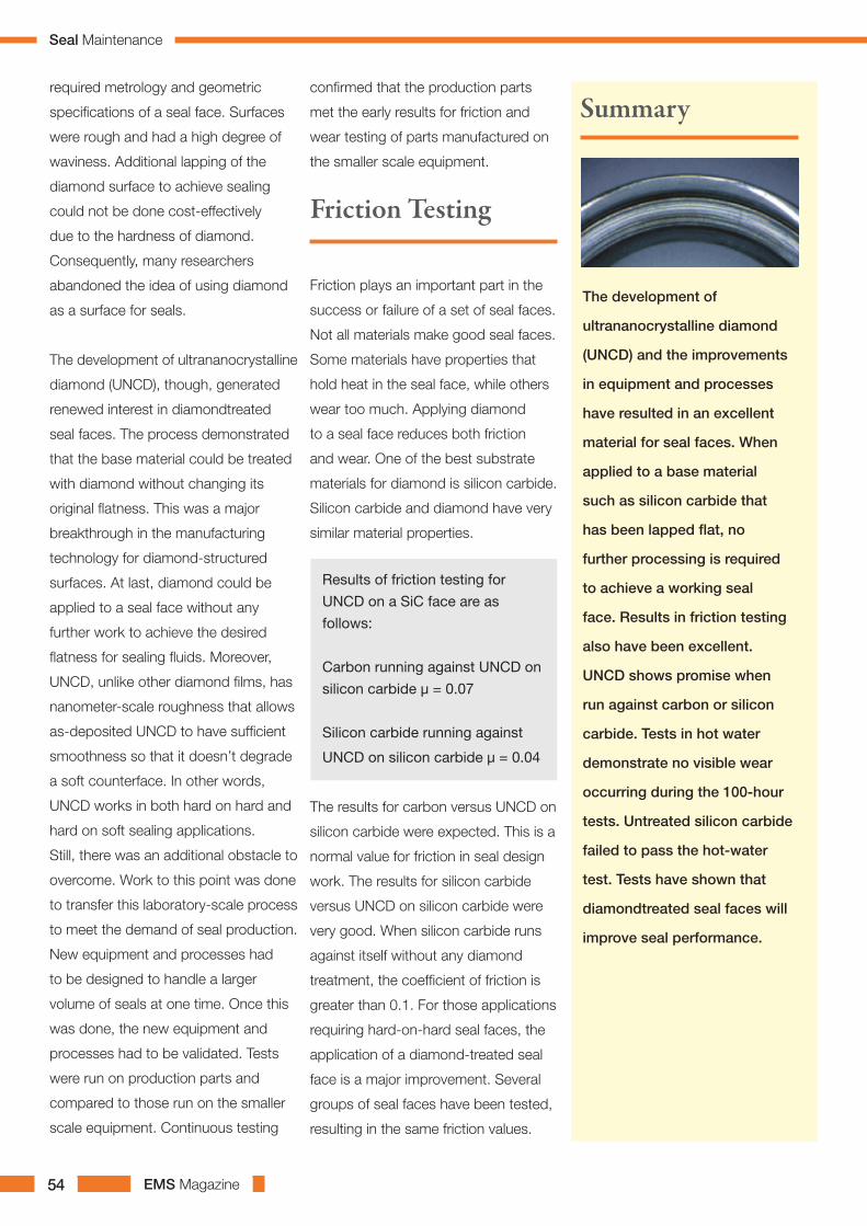
EMS Magazine54
required metrology and geometric
specifications of a seal face. Surfaces
were rough and had a high degree of
waviness. Additional lapping of the
diamond surface to achieve sealing
could not be done cost-effectively
due to the hardness of diamond.
Consequently, many researchers
abandoned the idea of using diamond
as a surface for seals.
The development of ultrananocrystalline
diamond (UNCD), though, generated
renewed interest in diamondtreated
seal faces. The process demonstrated
that the base material could be treated
with diamond without changing its
original flatness. This was a major
breakthrough in the manufacturing
technology for diamond-structured
surfaces. At last, diamond could be
applied to a seal face without any
further work to achieve the desired
flatness for sealing fluids. Moreover,
UNCD, unlike other diamond films, has
nanometer-scale roughness that allows
as-deposited UNCD to have sufficient
smoothness so that it doesn’t degrade
a soft counterface. In other words,
UNCD works in both hard on hard and
hard on soft sealing applications.
Still, there was an additional obstacle to
overcome. Work to this point was done
to transfer this laboratory-scale process
to meet the demand of seal production.
New equipment and processes had
to be designed to handle a larger
volume of seals at one time. Once this
was done, the new equipment and
processes had to be validated. Tests
were run on production parts and
compared to those run on the smaller
scale equipment. Continuous testing
confirmed that the production parts
met the early results for friction and
wear testing of parts manufactured on
the smaller scale equipment.
Friction plays an important part in the
success or failure of a set of seal faces.
Not all materials make good seal faces.
Some materials have properties that
hold heat in the seal face, while others
wear too much. Applying diamond
to a seal face reduces both friction
and wear. One of the best substrate
materials for diamond is silicon carbide.
Silicon carbide and diamond have very
similar material properties.
Results of friction testing for
UNCD on a SiC face are as
follows:
Carbon running against UNCD on
silicon carbide µ = 0.07
Silicon carbide running against
UNCD on silicon carbide µ = 0.04
The results for carbon versus UNCD on
silicon carbide were expected. This is a
normal value for friction in seal design
work. The results for silicon carbide
versus UNCD on silicon carbide were
very good. When silicon carbide runs
against itself without any diamond
treatment, the coefficient of friction is
greater than 0.1. For those applications
requiring hard-on-hard seal faces, the
application of a diamond-treated seal
face is a major improvement. Several
groups of seal faces have been tested,
resulting in the same friction values.
Friction Testing
The development of
ultrananocrystalline diamond
(UNCD) and the improvements
in equipment and processes
have resulted in an excellent
material for seal faces. When
applied to a base material
such as silicon carbide that
has been lapped flat, no
further processing is required
to achieve a working seal
face. Results in friction testing
also have been excellent.
UNCD shows promise when
run against carbon or silicon
carbide. Tests in hot water
demonstrate no visible wear
occurring during the 100-hour
tests. Untreated silicon carbide
failed to pass the hot-water
test. Tests have shown that
diamondtreated seal faces will
improve seal performance.
Summary
Seal Maintenance

EMS Magazine 55
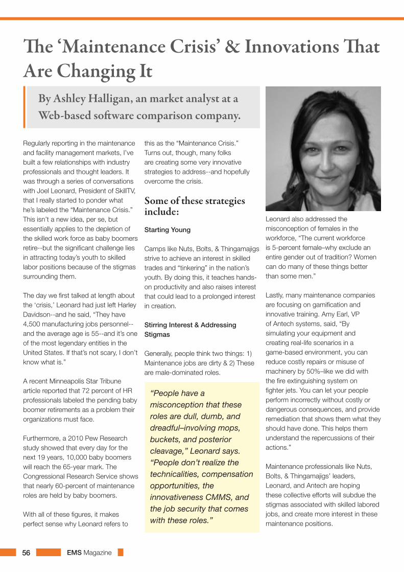
EMS Magazine56
Regularly reporting in the maintenance and facility management markets, I’ve built a few relationships with industry professionals and thought leaders. It was through a series of conversations with Joel Leonard, President of SkillTV, that I really started to ponder what he’s labeled the “Maintenance Crisis.” This isn’t a new idea, per se, but essentially applies to the depletion of the skilled work force as baby boomers retire--but the significant challenge lies in attracting today’s youth to skilled labor positions because of the stigmas surrounding them.
The day we first talked at length about the ‘crisis,’ Leonard had just left Harley Davidson--and he said, “They have 4,500 manufacturing jobs personnel--and the average age is 55--and it’s one of the most legendary entities in the United States. If that’s not scary, I don’t know what is.”
A recent Minneapolis Star Tribune article reported that 72 percent of HR professionals labeled the pending baby boomer retirements as a problem their organizations must face.
Furthermore, a 2010 Pew Research study showed that every day for the next 19 years, 10,000 baby boomers will reach the 65-year mark. The Congressional Research Service shows that nearly 60-percent of maintenance roles are held by baby boomers.
With all of these figures, it makes perfect sense why Leonard refers to
this as the “Maintenance Crisis.” Turns out, though, many folks are creating some very innovative strategies to address--and hopefully overcome the crisis.
Some of these strategies include:
Starting Young
Camps like Nuts, Bolts, & Thingamajigs strive to achieve an interest in skilled trades and “tinkering” in the nation’s youth. By doing this, it teaches hands-on productivity and also raises interest that could lead to a prolonged interest in creation. Stirring Interest & Addressing Stigmas
Generally, people think two things: 1) Maintenance jobs are dirty & 2) These are male-dominated roles.
“People have a misconception that these roles are dull, dumb, and dreadful–involving mops, buckets, and posterior cleavage,” Leonard says. “People don’t realize the technicalities, compensation opportunities, the innovativeness CMMS, and the job security that comes with these roles.”
Leonard also addressed the misconception of females in the workforce, “The current workforce is 5-percent female–why exclude an entire gender out of tradition? Women can do many of these things better than some men.”
Lastly, many maintenance companies are focusing on gamification and innovative training. Amy Earl, VP of Antech systems, said, “By simulating your equipment and creating real-life scenarios in a game-based environment, you can reduce costly repairs or misuse of machinery by 50%–like we did with the fire extinguishing system on fighter jets. You can let your people perform incorrectly without costly or dangerous consequences, and provide remediation that shows them what they should have done. This helps them understand the repercussions of their actions.”
Maintenance professionals like Nuts, Bolts, & Thingamajigs’ leaders, Leonard, and Antech are hoping these collective efforts will subdue the stigmas associated with skilled labored jobs, and create more interest in these maintenance positions.
The ‘Maintenance Crisis’ & Innovations That Are Changing It
By Ashley Halligan, an market analyst at a Web-based software comparison company.
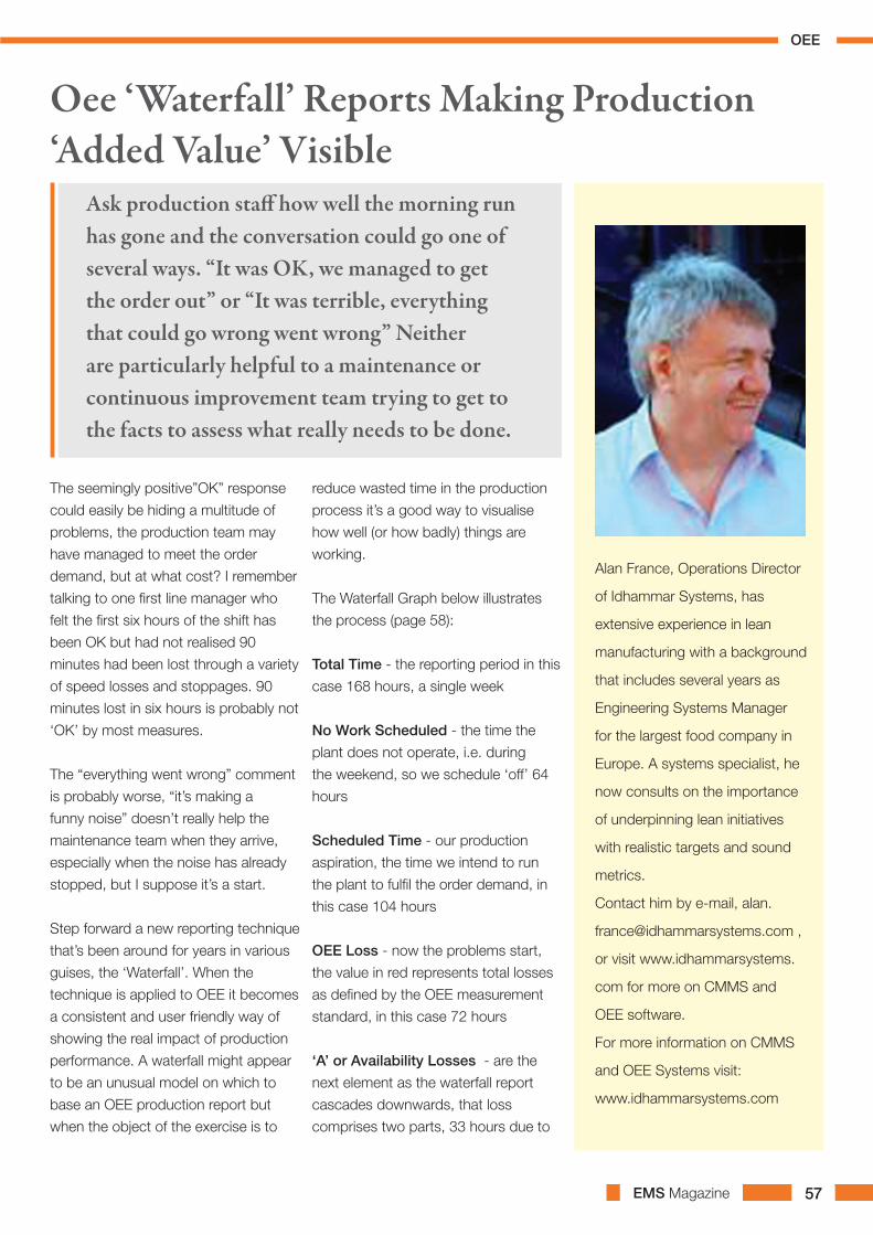
EMS Magazine 57
The seemingly positive”OK” response
could easily be hiding a multitude of
problems, the production team may
have managed to meet the order
demand, but at what cost? I remember
talking to one first line manager who
felt the first six hours of the shift has
been OK but had not realised 90
minutes had been lost through a variety
of speed losses and stoppages. 90
minutes lost in six hours is probably not
‘OK’ by most measures.
The “everything went wrong” comment
is probably worse, “it’s making a
funny noise” doesn’t really help the
maintenance team when they arrive,
especially when the noise has already
stopped, but I suppose it’s a start.
Step forward a new reporting technique
that’s been around for years in various
guises, the ‘Waterfall’. When the
technique is applied to OEE it becomes
a consistent and user friendly way of
showing the real impact of production
performance. A waterfall might appear
to be an unusual model on which to
base an OEE production report but
when the object of the exercise is to
reduce wasted time in the production
process it’s a good way to visualise
how well (or how badly) things are
working.
The Waterfall Graph below illustrates
the process (page 58):
Total Time - the reporting period in this
case 168 hours, a single week
No Work Scheduled - the time the
plant does not operate, i.e. during
the weekend, so we schedule ‘off’ 64
hours
Scheduled Time - our production
aspiration, the time we intend to run
the plant to fulfil the order demand, in
this case 104 hours
OEE Loss - now the problems start,
the value in red represents total losses
as defined by the OEE measurement
standard, in this case 72 hours
‘A’ or Availability Losses - are the
next element as the waterfall report
cascades downwards, that loss
comprises two parts, 33 hours due to
Oee ‘Waterfall’ Reports Making Production ‘Added Value’ Visible
Ask production staff how well the morning run has gone and the conversation could go one of several ways. “It was OK, we managed to get the order out” or “It was terrible, everything that could go wrong went wrong” Neither are particularly helpful to a maintenance or continuous improvement team trying to get to the facts to assess what really needs to be done.
Alan France, Operations Director
of Idhammar Systems, has
extensive experience in lean
manufacturing with a background
that includes several years as
Engineering Systems Manager
for the largest food company in
Europe. A systems specialist, he
now consults on the importance
of underpinning lean initiatives
with realistic targets and sound
metrics.
Contact him by e-mail, alan.
or visit www.idhammarsystems.
com for more on CMMS and
OEE software.
For more information on CMMS
and OEE Systems visit:
www.idhammarsystems.com
OEE
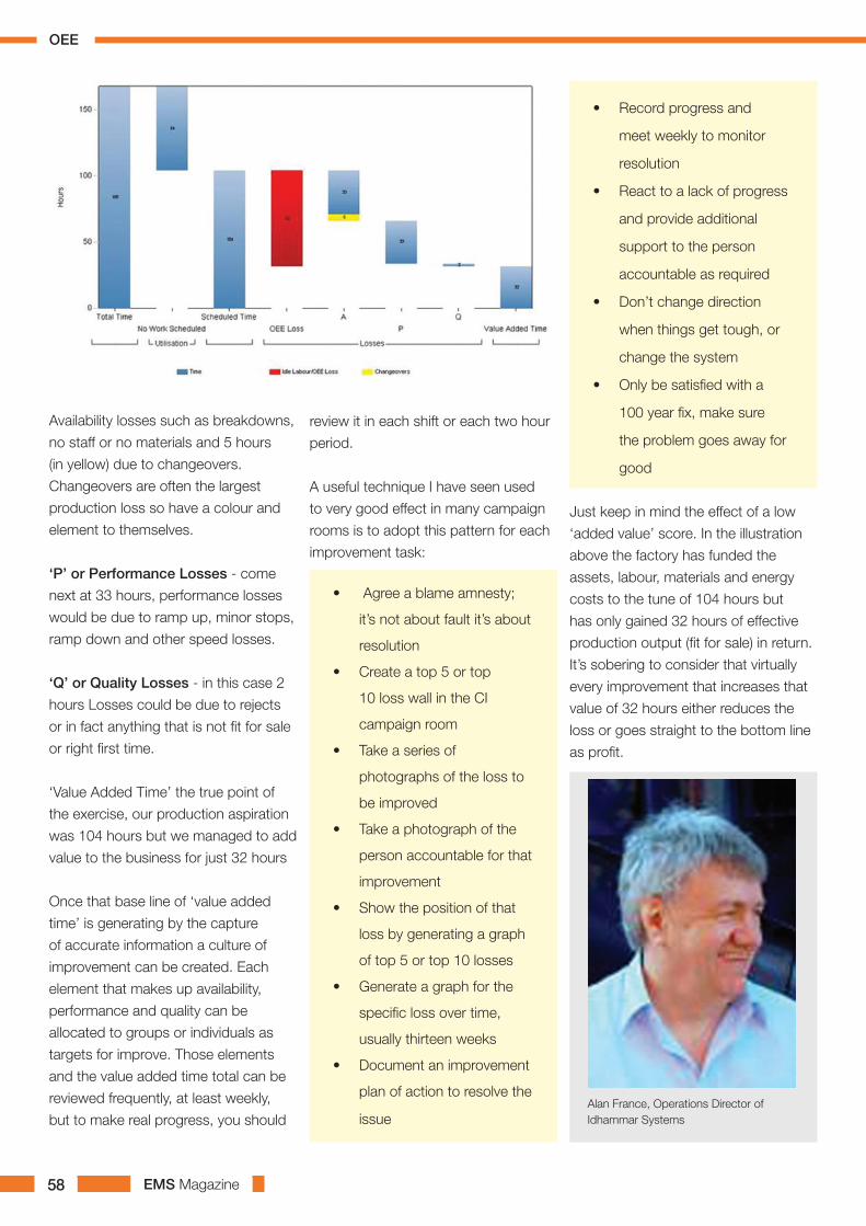
EMS Magazine58
Availability losses such as breakdowns,
no staff or no materials and 5 hours
(in yellow) due to changeovers.
Changeovers are often the largest
production loss so have a colour and
element to themselves.
‘P’ or Performance Losses - come
next at 33 hours, performance losses
would be due to ramp up, minor stops,
ramp down and other speed losses.
‘Q’ or Quality Losses - in this case 2
hours Losses could be due to rejects
or in fact anything that is not fit for sale
or right first time.
‘Value Added Time’ the true point of
the exercise, our production aspiration
was 104 hours but we managed to add
value to the business for just 32 hours
Once that base line of ‘value added
time’ is generating by the capture
of accurate information a culture of
improvement can be created. Each
element that makes up availability,
performance and quality can be
allocated to groups or individuals as
targets for improve. Those elements
and the value added time total can be
reviewed frequently, at least weekly,
but to make real progress, you should
review it in each shift or each two hour
period.
A useful technique I have seen used
to very good effect in many campaign
rooms is to adopt this pattern for each
improvement task:
• Agree a blame amnesty;
it’s not about fault it’s about
resolution
• Create a top 5 or top
10 loss wall in the CI
campaign room
• Take a series of
photographs of the loss to
be improved
• Take a photograph of the
person accountable for that
improvement
• Show the position of that
loss by generating a graph
of top 5 or top 10 losses
• Generate a graph for the
specific loss over time,
usually thirteen weeks
• Document an improvement
plan of action to resolve the
issue
• Record progress and
meet weekly to monitor
resolution
• React to a lack of progress
and provide additional
support to the person
accountable as required
• Don’t change direction
when things get tough, or
change the system
• Only be satisfied with a
100 year fix, make sure
the problem goes away for
good
Just keep in mind the effect of a low
‘added value’ score. In the illustration
above the factory has funded the
assets, labour, materials and energy
costs to the tune of 104 hours but
has only gained 32 hours of effective
production output (fit for sale) in return.
It’s sobering to consider that virtually
every improvement that increases that
value of 32 hours either reduces the
loss or goes straight to the bottom line
as profit.
Alan France, Operations Director of Idhammar Systems
OEE

EMS Magazine 59

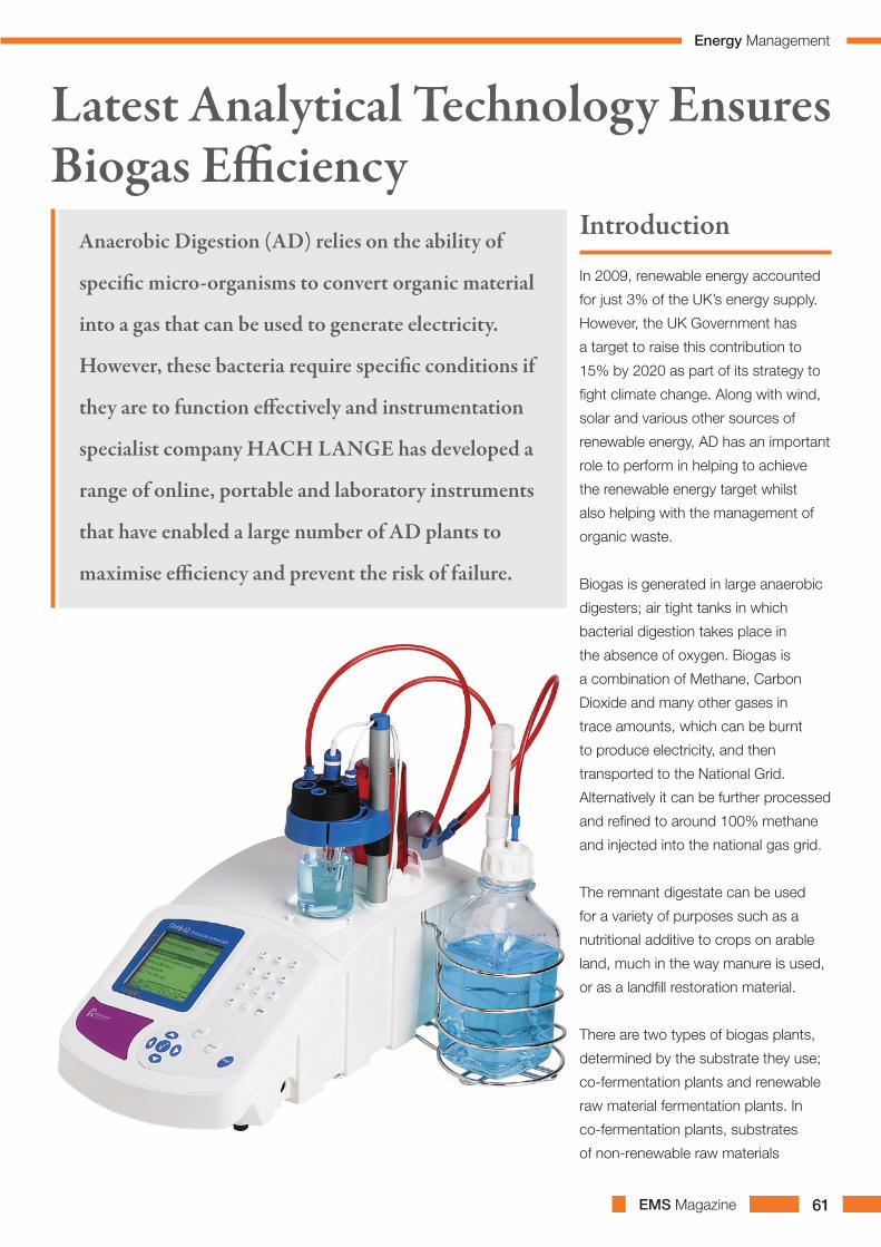
EMS Magazine 61
In 2009, renewable energy accounted
for just 3% of the UK’s energy supply.
However, the UK Government has
a target to raise this contribution to
15% by 2020 as part of its strategy to
fight climate change. Along with wind,
solar and various other sources of
renewable energy, AD has an important
role to perform in helping to achieve
the renewable energy target whilst
also helping with the management of
organic waste.
Biogas is generated in large anaerobic
digesters; air tight tanks in which
bacterial digestion takes place in
the absence of oxygen. Biogas is
a combination of Methane, Carbon
Dioxide and many other gases in
trace amounts, which can be burnt
to produce electricity, and then
transported to the National Grid.
Alternatively it can be further processed
and refined to around 100% methane
and injected into the national gas grid.
The remnant digestate can be used
for a variety of purposes such as a
nutritional additive to crops on arable
land, much in the way manure is used,
or as a landfill restoration material.
There are two types of biogas plants,
determined by the substrate they use;
co-fermentation plants and renewable
raw material fermentation plants. In
co-fermentation plants, substrates
of non-renewable raw materials
Latest Analytical Technology Ensures Biogas Efficiency
Anaerobic Digestion (AD) relies on the ability of
specific micro-organisms to convert organic material
into a gas that can be used to generate electricity.
However, these bacteria require specific conditions if
they are to function effectively and instrumentation
specialist company HACH LANGE has developed a
range of online, portable and laboratory instruments
that have enabled a large number of AD plants to
maximise efficiency and prevent the risk of failure.
Introduction
Energy Management

EMS Magazine62
are used, such as residues from fat
separators, food residues, flotation oil,
industrial waste products (glycerol or oil
sludge) and domestic organic waste.
Renewable raw material fermentation
plants utilise materials such as maize,
grass, complete cereal plants and
grains, sometimes together with
manure slurry.
Efficiency is vital to the success of
a biogas production plant; bacteria
require optimum conditions to
effectively produce biogas from the
digestion of organic matter. Plant
operators therefore have a strong
interest in the efficiency of their biogas
plant and the activity of the bacteria.
Consequently these production
plants require reliable, on-site analysis
in combination with continuously
operating process instruments.
Loading excessive levels of biomass
into a digester may have severe
economic consequences and could
potentially lead to biomass inactivation
and necessitate a cost-intensive
restart. Conversely, under-loading
a biomass digester could also have
financial implications, because less
electricity is produced and potential
revenue is lost. Substrate amounts
must be tailored to achieve the
optimum rate of bacterial digestion.
The degradation process which occurs
within the biogas plant digesters
does so in a highly sensitive microbial
environment. The digesting, methane-
producing bacteria, for example,
are highly temperature sensitive and
most active within the temperature
ranges of around 35 to 40 DegC and
between 54 to approximately 57 DegC.
The specific nature of the microbial
environment inside the digesters must
be maintained throughout fermentation
to increase production and avoid
inactivation of the highly responsive
bacteria.
Process monitoring instruments used across
the fermentation cycle allow operators to
constantly supervise the anaerobic digestion
rate and biogas production.
The Need For Testing And Monitoring
and the values generated enable the
system supervisor to identify potential
process problems such as the
imminent inversion of digester biology,
so that countermeasures can be
initiated. The FOS stands for Flüchtige
Organische Säuren, i.e. volatile organic
acids while TAC stands for Totales
Anorganisches Carbonat, i.e. total
inorganic carbonate (alkaline buffer
capacity).
To measure the FOS/TAC ratio with
the TIM 840 titrator, 5ml of sample is
added to a titration beaker containing
a follower bar. 50ml of distilled water
is then added and the measurement
is started. The addition of reagents is
then conducted automatically by the
titrator which saves operator time and
reduces the potential for human error.
After about 5 minutes the TAC and
FOS values are calculated automatically
using a pre-programmed formula.
All measured values can be stored in
the autotitrator and/or sent to a printer
or PC.
The FOS/TAC ratio provides an
indication of the acidification of the
fermenter, which is an important
measurement because a low acid
content demonstrates that the rate of
bacterial digestion is not high enough.
Conversely, too high an acid content
means bacterial digestion is exceeding
required levels, due to an overloading
of substrate.
Monitoring Equipment
HACH LANGE provides portable,
laboratory and online monitoring
systems that facilitate examination
at key points within the fermentation
process, including eluate analysis,
where the substrate is fed into the
digester, but also within the digester
itself. Online process analysis
instrumentation can be employed
to continuously maintain optimum
conditions within the biogas plant and/
or samples can be collected regularly
for analysis.
Different analytical instruments
are required for different stages of
the fermentation process: at the
substrate entry point; within the main
digester; in post-fermentation tanks
and to continuously monitor biogas
production.
One of the most important
measurements for assessing
fermentation progress is known as the
FOS/TAC ratio. This is determined by
the HACH LANGE TIM 840 Titrator,
Energy Management
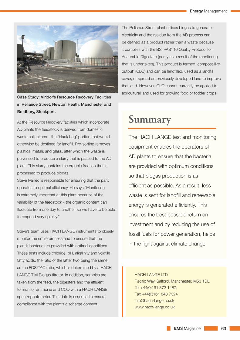
EMS Magazine 63
HACH LANGE LTD
Pacific Way, Salford, Manchester. M50 1DL
Tel +44(0)161 872 1487,
Fax +44(0)161 848 7324
www.hach-lange.co.uk
Case Study: Viridor’s Resource Recovery Facilities
in Reliance Street, Newton Heath, Manchester and
Bredbury, Stockport.
At the Resource Recovery facilities which incorporate
AD plants the feedstock is derived from domestic
waste collections – the ‘black bag’ portion that would
otherwise be destined for landfill. Pre-sorting removes
plastics, metals and glass, after which the waste is
pulverised to produce a slurry that is passed to the AD
plant. This slurry contains the organic fraction that is
processed to produce biogas.
Steve Ivanec is responsible for ensuring that the pant
operates to optimal efficiency. He says “Monitoring
is extremely important at this plant because of the
variability of the feedstock - the organic content can
fluctuate from one day to another, so we have to be able
to respond very quickly.”
Steve’s team uses HACH LANGE instruments to closely
monitor the entire process and to ensure that the
plant’s bacteria are provided with optimal conditions.
These tests include chloride, pH, alkalinity and volatile
fatty acids; the ratio of the latter two being the same
as the FOS/TAC ratio, which is determined by a HACH
LANGE TIM Biogas titrator. In addition, samples are
taken from the feed, the digesters and the effluent
to monitor ammonia and COD with a HACH LANGE
spectrophotometer. This data is essential to ensure
compliance with the plant’s discharge consent.
The HACH LANGE test and monitoring
equipment enables the operators of
AD plants to ensure that the bacteria
are provided with optimum conditions
so that biogas production is as
efficient as possible. As a result, less
waste is sent for landfill and renewable
energy is generated efficiently. This
ensures the best possible return on
investment and by reducing the use of
fossil fuels for power generation, helps
in the fight against climate change.
The Reliance Street plant utilises biogas to generate
electricity and the residue from the AD process can
be defined as a product rather than a waste because
it complies with the BSI PAS110 Quality Protocol for
Anaerobic Digestate (partly as a result of the monitoring
that is undertaken). This product is termed ‘compost-like
output’ (CLO) and can be landfilled, used as a landfill
cover, or spread on previously developed land to improve
that land. However, CLO cannot currently be applied to
agricultural land used for growing food or fodder crops.
Summary
Energy Management
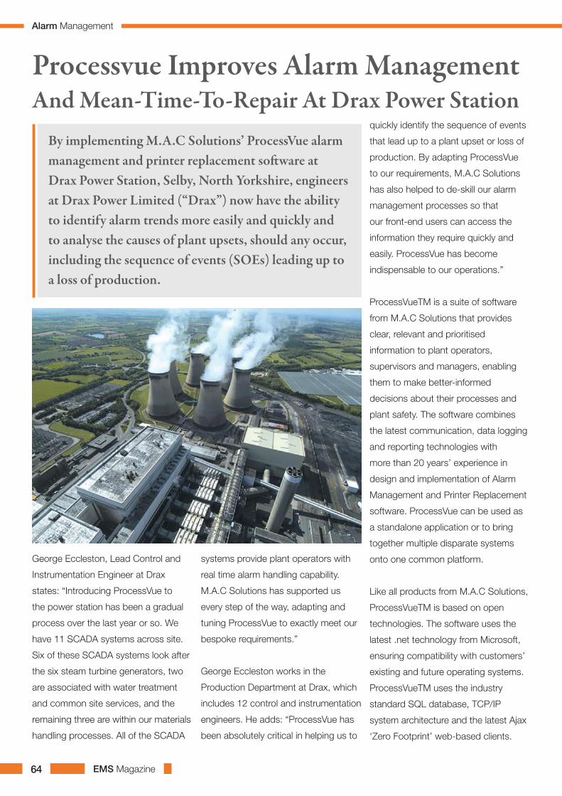
EMS Magazine64
George Eccleston, Lead Control and
Instrumentation Engineer at Drax
states: “Introducing ProcessVue to
the power station has been a gradual
process over the last year or so. We
have 11 SCADA systems across site.
Six of these SCADA systems look after
the six steam turbine generators, two
are associated with water treatment
and common site services, and the
remaining three are within our materials
handling processes. All of the SCADA
systems provide plant operators with
real time alarm handling capability.
M.A.C Solutions has supported us
every step of the way, adapting and
tuning ProcessVue to exactly meet our
bespoke requirements.”
George Eccleston works in the
Production Department at Drax, which
includes 12 control and instrumentation
engineers. He adds: “ProcessVue has
been absolutely critical in helping us to
quickly identify the sequence of events
that lead up to a plant upset or loss of
production. By adapting ProcessVue
to our requirements, M.A.C Solutions
has also helped to de-skill our alarm
management processes so that
our front-end users can access the
information they require quickly and
easily. ProcessVue has become
indispensable to our operations.”
ProcessVueTM is a suite of software
from M.A.C Solutions that provides
clear, relevant and prioritised
information to plant operators,
supervisors and managers, enabling
them to make better-informed
decisions about their processes and
plant safety. The software combines
the latest communication, data logging
and reporting technologies with
more than 20 years’ experience in
design and implementation of Alarm
Management and Printer Replacement
software. ProcessVue can be used as
a standalone application or to bring
together multiple disparate systems
onto one common platform.
Like all products from M.A.C Solutions,
ProcessVueTM is based on open
technologies. The software uses the
latest .net technology from Microsoft,
ensuring compatibility with customers’
existing and future operating systems.
ProcessVueTM uses the industry
standard SQL database, TCP/IP
system architecture and the latest Ajax
‘Zero Footprint’ web-based clients.
Processvue Improves Alarm Management And Mean-Time-To-Repair At Drax Power Station
By implementing M.A.C Solutions’ ProcessVue alarm management and printer replacement software at Drax Power Station, Selby, North Yorkshire, engineers at Drax Power Limited (“Drax”) now have the ability to identify alarm trends more easily and quickly and to analyse the causes of plant upsets, should any occur, including the sequence of events (SOEs) leading up to a loss of production.
Alarm Management
EMS Magazine 65
ProcessVue’s architecture is designed
to enable interfacing with almost any
control system, bringing all data into
a standard configurable format. This
allows simple Operator Sequence of
Event [SOE] display and high level
KPI reporting and analysis. These
disparate systems might include
SCADA systems, Distributed Control
Systems, emergency shutdown, fire
control, buildings management or
any system that can output data in
an ASCII format. With ProcessVue, all
alarm sources are put into a standard,
open format so that operators can view
the KPIs without anyone having to write
complex code.
Drax Power Station runs on various
DCS system (five different technologies)
linked to eight separate SCADA
systems, which handle all process
data and more than 70,000 separate
alarms. As George Eccleston states:
“Prior to implementing ProcessVue,
the alarms coming from our SCADA
system were very detailed and did not
offer a concise message to our Process
Engineers. We therefore wanted
software that would better manage
the structure of the alarm message by
parsing it and then sending the new,
reconstructed message out to our SOE
web clients [which were installed by
M.A.C Solutions in January 2010].
“It is critical that our IT systems
enable us to access process data and
alarms quickly and easily. We have
literally thousands of events each day
that need to be recorded, as well as
safety-critical processes that need
monitoring and managing in terms of
process alarms.
“ProcessVue is one of the key tools
enabling root cause analysis of events
at the power station, thereby helping
us to investigate and report on these
events to senior management and
other parts of our organisation.”
He continues: “Drax prides itself
on maintaining high availability and
reliability of the power station. Loss of
production time could be costly and
we have set ourselves a long term
target for managing any reduction in
plant availability, excluding planned
outages. Knowing that our engineers
can rectify any issues that arise as
quickly as possible is essential, and
since implementing ProcessVue
we have significantly improved our
mean-time-to-repair critical items
of plant and equipment. In addition,
we are also benefiting from having
“Introducing ProcessVue to the power station has been
a gradual process over the last year or so. We have
11 SCADA systems across site. Six of these SCADA
systems look after the six steam turbine generators,
two are associated with water treatment and common
site services, and the remaining three are within our
materials handling processes. All of the SCADA systems
provide plant operators with real time alarm handling
capability. M.A.C Solutions has supported us every step
of the way, adapting and tuning ProcessVue to exactly
meet our bespoke requirements.”
ProcessVue at Drax Power
complete transparency of information
and the fact that our dependency on
paper-based systems and reporting
has disappeared.”
“If the plant has a trip on a safety-
critical system such as the level
monitoring of boiler water, this needs
to be recorded for audit and reporting
purposes. All safety-critical processes
at Selby are monitored and recorded
using ProcessVue.
“ProcessVue can be interrogated to
give all alarm occurrences between,
say, 01.00 and 02.00 on that day and
then analyse the results. Back in the
1990s, we had around 20 line printers,
which ran continuously, churning out
alarm reports, which were only ever
read if there was a problem. Obviously,
reading these types of reports was very
time consuming and it was difficult to
spot trends or key events in the data,
the technology could also make the
whole system unreliable.
Alarm Management

EMS Magazine66
“Phase One implementation of Alarm
Management at Drax was all about
moving towards a paperless system
by installing printer replacement
software, which we did with M.A.C
Solutions’ help. Phase Two focused
on retrieving the data, receiving the
alarms and recording this information
on a PC-based system. Phase Three
is where we are now, with the ability
to recognise different types of alarm
messages and to sort these into a
database using standard Microsoft
SQL tools. What comes next is moving
towards automating these reports and
analysing the data.”
In May 2011, M.A.C Solutions began
implementing the ProcessVue Analyser
software module at Drax. ProcessVue
Analyser is a business intelligence
software module, which offers a wide
range of high level reporting features,
including event reporting, frequency
analysis, standing and chattering
alarm reporting, operator response
times, and customised reporting.
The Analyser Web Client enables the
presentation of EEMUA alarm-based
KPIs through dashboards.
A properly managed alarm system
is now a critical, integral part of any
production or process manufacturing
facility. Since its establishment in 1991,
EEMUA 191 has become the globally
accepted standard for good practice
alarm management. ProcessVueTM
reporting is based on EEMUA 191
guidelines.
To establish an alarm management
system based on these guidelines
or to ascertain if a current system
is operating effectively and within
the guidelines, alarm data must be
collected and analysed on a continuous
basis. Just collecting this data can be
a challenge in itself. Bringing this data
into a usable format for control room
operators and reporting on this data
to Alarm Managers are two critical
functions.
Features within ProcessVueTM
include advanced KPI reporting based
on EEMUA 191 guidelines; alarm
rationalisation (locating ‘bad actors’
and ‘nuisance alarms’); Sequence of
Event and real time display in web
browser; alarm system benchmarking;
alarm and event analysis; and alarm
and event archiving.
Software to EEMUA 191 Guidelines
George Eccleston continues:
“ProcessVue helps us to identify
any nuisance alarms, for example,
chattering events, which can then be
targeted for rectification or repair, as
these can often hide genuine alarms.
If the software didn’t help to do this,
the risk is that key events could be
hidden within a nuisance alarm flood
or shower. Since October 2011 when
Analyser was officially released here,
the software has enabled us to identify
these nuisance alarms, which in turn
has reduced alarm load significantly
and to shelve those alarms in a
practical logical way.”
ProcessVueTM is also being used by
other major UK-based nuclear and
energy utility companies. As Jason
Cook, ProcessVue Sales Engineer at
M.A.C Solutions states: “Companies
such as Drax are very keen to improve
their alarm management with a view to
making more informed decisions about
their plant and processes in terms of
KPIs and employee health & safety.
How a power station manages and
reacts to critical process alarms could
save plant and even lives and this is
where ProcessVue really comes into its
own.”
For more information on
ProcessVue, visit the website
at www.ProcessVue.com or
telephone 01527 592999, or
email [email protected]
Features within
ProcessVueTM
include advanced KPI
reporting based on
EEMUA 191 guidelines;
alarm rationalisation
(locating ‘bad actors’
and ‘nuisance alarms’);
Sequence of Event and
real time display in web
browser; alarm system
benchmarking; alarm and
event analysis; and alarm
and event archiving.
Alarm Management
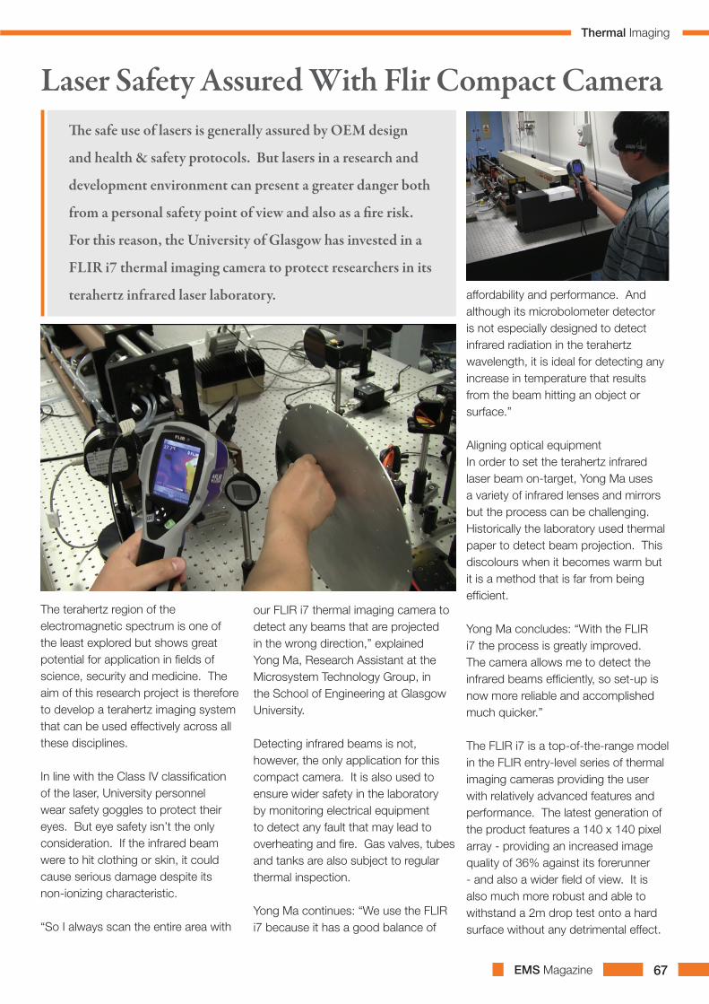
EMS Magazine 67
The terahertz region of the electromagnetic spectrum is one of the least explored but shows great potential for application in fields of science, security and medicine. The aim of this research project is therefore to develop a terahertz imaging system that can be used effectively across all these disciplines.
In line with the Class IV classification of the laser, University personnel wear safety goggles to protect their eyes. But eye safety isn’t the only consideration. If the infrared beam were to hit clothing or skin, it could cause serious damage despite its non-ionizing characteristic.
“So I always scan the entire area with
our FLIR i7 thermal imaging camera to detect any beams that are projected in the wrong direction,” explained Yong Ma, Research Assistant at the Microsystem Technology Group, in the School of Engineering at Glasgow University.
Detecting infrared beams is not, however, the only application for this compact camera. It is also used to ensure wider safety in the laboratory by monitoring electrical equipment to detect any fault that may lead to overheating and fire. Gas valves, tubes and tanks are also subject to regular thermal inspection.
Yong Ma continues: “We use the FLIR i7 because it has a good balance of
Laser Safety Assured With Flir Compact CameraThe safe use of lasers is generally assured by OEM design
and health & safety protocols. But lasers in a research and
development environment can present a greater danger both
from a personal safety point of view and also as a fire risk.
For this reason, the University of Glasgow has invested in a
FLIR i7 thermal imaging camera to protect researchers in its
terahertz infrared laser laboratory. affordability and performance. And although its microbolometer detector is not especially designed to detect infrared radiation in the terahertz wavelength, it is ideal for detecting any increase in temperature that results from the beam hitting an object or surface.”
Aligning optical equipmentIn order to set the terahertz infrared laser beam on-target, Yong Ma uses a variety of infrared lenses and mirrors but the process can be challenging. Historically the laboratory used thermal paper to detect beam projection. This discolours when it becomes warm but it is a method that is far from being efficient.
Yong Ma concludes: “With the FLIR i7 the process is greatly improved. The camera allows me to detect the infrared beams efficiently, so set-up is now more reliable and accomplished much quicker.”
The FLIR i7 is a top-of-the-range model in the FLIR entry-level series of thermal imaging cameras providing the user with relatively advanced features and performance. The latest generation of the product features a 140 x 140 pixel array - providing an increased image quality of 36% against its forerunner - and also a wider field of view. It is also much more robust and able to withstand a 2m drop test onto a hard surface without any detrimental effect.
Thermal Imaging
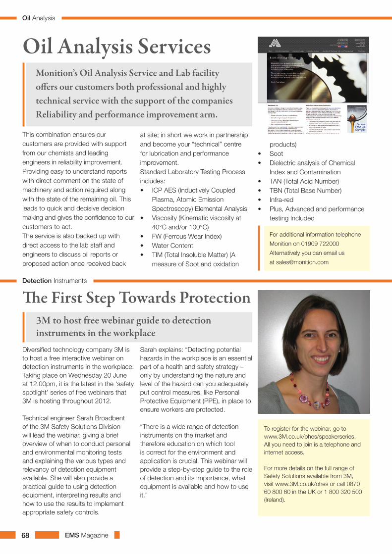
EMS Magazine68
This combination ensures our customers are provided with support from our chemists and leading engineers in reliability improvement. Providing easy to understand reports with direct comment on the state of machinery and action required along with the state of the remaining oil. This leads to quick and decisive decision making and gives the confidence to our customers to act.The service is also backed up with direct access to the lab staff and engineers to discuss oil reports or proposed action once received back
at site; in short we work in partnership and become your “technical” centre for lubrication and performance improvement.Standard Laboratory Testing Process includes:• ICP AES (Inductively Coupled
Plasma, Atomic Emission Spectroscopy) Elemental Analysis
• Viscosity (Kinematic viscosity at 40°C and/or 100°C)
• FW (Ferrous Wear Index)• Water Content• TIM (Total Insoluble Matter) (A
measure of Soot and oxidation
Oil Analysis ServicesMonition’s Oil Analysis Service and Lab facility offers our customers both professional and highly technical service with the support of the companies Reliability and performance improvement arm.
products)• Soot• Dielectric analysis of Chemical
Index and Contamination• TAN (Total Acid Number)• TBN (Total Base Number)• Infra-red• Plus, Advanced and performance
testing Included
For additional information telephone
Monition on 01909 722000
Alternatively you can email us
Diversified technology company 3M is to host a free interactive webinar on detection instruments in the workplace. Taking place on Wednesday 20 June at 12.00pm, it is the latest in the ‘safety spotlight’ series of free webinars that 3M is hosting throughout 2012.
Technical engineer Sarah Broadbent of the 3M Safety Solutions Division will lead the webinar, giving a brief overview of when to conduct personal and environmental monitoring tests and explaining the various types and relevancy of detection equipment available. She will also provide a practical guide to using detection equipment, interpreting results and how to use the results to implement appropriate safety controls.
Sarah explains: “Detecting potential hazards in the workplace is an essential part of a health and safety strategy – only by understanding the nature and level of the hazard can you adequately put control measures, like Personal Protective Equipment (PPE), in place to ensure workers are protected.
“There is a wide range of detection instruments on the market and therefore education on which tool is correct for the environment and application is crucial. This webinar will provide a step-by-step guide to the role of detection and its importance, what equipment is available and how to use it.”
The First Step Towards Protection3M to host free webinar guide to detection instruments in the workplace
To register for the webinar, go to www.3M.co.uk/ohes/speakerseries. All you need to join is a telephone and internet access.
For more details on the full range of Safety Solutions available from 3M, visit www.3M.co.uk/ohes or call 0870 60 800 60 in the UK or 1 800 320 500 (Ireland).
Detection Instruments
Oil Analysis

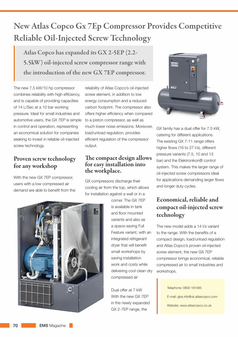
The new 7.5 kW/10 hp compressor
combines reliability with high efficiency,
and is capable of providing capacities
of 14 L/Sec at a 10 bar working
pressure. Ideal for small industries and
automotive users, the GX 7EP is simple
in control and operation, representing
an economical solution for companies
seeking to invest in reliable oil-injected
screw technology.
Proven screw technology for any workshop
With the new GX 7EP compressor,
users with a low compressed air
demand are able to benefit from the
reliability of Atlas Copco’s oil-injected
screw element, in addition to low
energy consumption and a reduced
carbon footprint. The compressor also
offers higher efficiency when compared
to a piston compressor, as well as
much lower noise emissions. Moreover,
load/unload regulation, provides
efficient regulation of the compressor
output.
The compact design allows for easy installation into the workplace. GX compressors discharge their
cooling air from the top, which allows
for installation against a wall or in a
corner. The GX 7EP
is available in tank
and floor mounted
variants and also as
a space-saving Full
Feature variant, with an
integrated refrigerant
dryer that will benefit
small workshops by
saving installation
work and costs while
delivering cool clean dry
compressed air
Dual offer at 7 kW
With the new GX 7EP
in the newly expanded
GX 2-7EP range, the
GX family has a dual offer for 7.5 kW,
catering for different applications.
The existing GX 7-11 range offers
higher flows (16 to 27 l/s), different
pressure variants (7.5, 10 and 13
bar) and the Elektronikon® control
system. This makes the larger range of
oil-injected screw compressors ideal
for applications demanding larger flows
and longer duty cycles.
Economical, reliable and compact oil-injected screw technology
The new model adds a 14 l/s variant
to the range. With the benefits of a
compact design, load/unload regulation
and Atlas Copco’s proven oil-injected
screw element, the new GX 7EP
compressor brings economical, reliable
compressed air to small industries and
workshops.
New Atlas Copco Gx 7Ep Compressor Provides Competitive Reliable Oil-Injected Screw Technology
Atlas Copco has expanded its GX 2-5EP (2.2-
5.5kW) oil-injected screw compressor range with
the introduction of the new GX 7EP compressor.
Telephone: 0800 181085
E-mail: [email protected]
Website: www.atlascopco.co.uk
EMS Magazine70


EMS Magazine72
Buyers Guide

EMS Magazine 73
Adver
tise H
ere
Buyers Guide

EMS Magazine74
Buyers Guide