Embed Size (px)
Citation preview

King Fahd University of Petroleum & Minerals CIVIL ENGINEERING DEPARTMENT
ENGINEERING GRAPHICS WITH
AUTOCAD CE101
LABORATORY MANUAL Mostefa Bouchama
July 2004

2
PREFACE This laboratory manual is designed to help students to use AutoCAD software for
engineering graphics.
The objectives of this manual are focused on how to use AutoCAD Program as a drawing
tool to draw objects and to develop basic concepts of engineering graphics, which are
essential for every student enrolled in engineering. It is also an excellent method of
learning the basics of AutoCAD software for more general purpose.
The class-work and homework assignments in this manual are arranged to match the
lecture sessions and are saved in the laboratory server.
Every command is explained, and examples of its use are shown during the lecture.
Mr. Mostfa Bouchama KFUPM, Dhahran, Saudi Arabia July 2004

3
CONTENTS
Preface
1. Introduction to AutoCAD
2. Drawing with AutoCAD
3. Text with AutoCAD
4. Orthographic Projection with AutoCAD
5. Geometric Construction with AutoCAD
6. Dimensions with AutoCAD
7. Sectioning with AutoCAD
8. Auxiliary views with AutoCAD
9. Surface Intersection with AutoCAD
10. Pictorial Drawing with AutoCAD
11. Freehand Sketching
12. 3D Drawing
Appendices:
A. Types of Lines in Engineering Graphics.
B. Types of Holes in Engineering Graphics.
C. AutoCAD Drawing and Editing Commands.
D. AutoCAD Function Keys.
E. Drawing Assignments.

4
1. INTRODUCTION TO AUTOCAD 1.1 Introduction:
In this section you are going to learn how to deal with the different AutoCAD
Windows and their contents.
When you start AutoCAD, three windows will be displayed on your screen:
a. AutoCAD window: AutoCAD Window consists of the following components:
- The standard menu bars
- The floating toolbars
- The command line
- The drawing area
- The status bar
Draw toolbar, Modify toolbar and Object Snap toolbar can be added to your AutoCAD
window by selecting the command View from the standard menu bar and choose any
toolbar from the toolbar dialog box.
b. Today Window: The use of Today window will help you:
- Start a new drawing
- Open a drawing
- Find a drawing
- Save a drawing
- Load AutoCAD symbol libraries
And you will also learn how to set up tools such as grid and snap to make drawing accurate
and easier.

5
c. Active Assistance Window: This window will display information about any
AutoCAD command.
1.2 Starting AutoCAD
Opening a Drawing.
a. From the pull-down menu, select the command Open.
b. Choose the drive where the drawing is saved.
c. Select the drawing you want open from the listed drawing names.
Starting a new drawing.
a. From the pull-down menu, select the command new.
b. Specify the new name of the drawing.
c. Click the OK box.
Prototype Drawing.
a. From the pull-down menu, select the command Open.
b. From the template dialog box, select the file you want to use.
c. You May choose to erase the contents of the file or modify it.
Any drawing can be used as a template.
Closing a drawing
You can close a drawing without exiting AutoCAD program, or you can close a drawing
and exiting AutoCAD program.
a. From the file menu, select Exit command, this will close the program.
b. From the file menu, select New or Open command, this will allow you to continue
using the program.

6
Saving a drawing.
a. When you type at the command line, or select from the file menu the save
command AutoCAD will display a save dialog box which will allow you to save
your drawing under the current name or choose another name.
b. If the drawing is already named, you can select the Qsave command from
the standard toolbar menu.
While you are working on your drawing, remember to save your work every 15 to 20
minutes. This way will save you time and frustrations in case something goes wrong with
your computer.

7
2. DRAWING WITH AUTOCAD
2.1 Drawing lines with AutoCAD
AutoCAD Entry Commands:
You can draw lines by using anyone of the five coordinate entry methods below:
- Absolute Rectangular Coordinates; (100, 0)
- Relative Rectangular Coordinates; @ (100, 0)
- Absolute Polar Coordinates; 100< 90º
- Relative Polar Coordinates; @ 100< -90º
- Direct Distance Entry; 100
Steps to begin drawing a line:
a- Type L at the command prompt and press the Enter key, or
b- Click le Line icon tool from the Draw toolbar.
In any case, AutoCAD will prompt you with a message asking you to specify the first
point to begin your line.
- You can type the coordinates (x, y) of a point, and press enter to start the line,
(Cartesian coordinate entry).
3- After you have selected the first point AutoCAD will ask you to specify the next point:
Enter @ 45, 0 to extend the line 45 units to the right from the last point, (Relative
Cartesian coordinate entry); then
- Enter @55< 30º to extend the line 55 units 30º upward from the last point, (relative
polar coordinate entry).
8
- Move the cursor horizontally to the right, and then enter 100 at the command prompt
to extend the line 100 units in the horizontal direction, (direct distance entry).
4- Press Enter to terminate the line command.
Drawing Hidden lines
- From the object properties toolbar, choose the line type command, and then select
Hidden
- Proceed as above.
40°
85°
120°90°
105° 109°90°
75°
60°
71°
45°
A
B
C
DE
F
G
H
I
J
K
AB = 65.5 FG = 44 BC =35 GH = 25CD =51 HI = 50DE =20 IJ = 50EF = 32 JK = 56 76
515125
25
51
51
13
C
51
25
13
40
7612
0°
130°70°
60°
This assignment will give practice in point selection.Use AutoCAD line command and anyone of the entry method to translate distances on your drawing.Select a starting point that will help you position your view on your screen.Notice all dimensions are in millimeter
Plate 1

9
2.2 Drawing circles with AutoCAD
You can draw circles by specifying one of the options cited below:
• The center and the radius or the diameter of the circle.
• 2 points (2P option). The two points are located on the circle.
• 3 points (3P option). The three points are located on the circle.
• 2 tangents and a radius, (TTR option).
• 3tangents, (TTT option).
Steps to begin drawing a Circle:
1- Type C at the command prompt and press the Enter key, or
2- Click le Circle icon tool from the Draw toolbar.
In any case, AutoCAD will prompt you with a message asking you to select one of the
options cited above.
A- Center Radius or Diameter Option:
a- You can type the coordinates (x, y) of a center point, or
b- Select a point on the screen, using the mouse.
c- After you have selected the center point AutoCAD will ask you to specify the radius
of the circle.
d- Press Enter to terminate the command.
B- 2P (two points) Option:
AutoCAD will ask you to specify 2 points (first end point of the diameter and then the
second end point of the diameter).

10
C- 3P (three points) Option:
AutoCAD will ask you to specify 3 points (first point on the circle, second point on the
circle and third point on the circle).
D- Tangent, Tangent, Radius Option:
AutoCAD will ask you to specify the first point on an object for the first tangent, the
second point on an object for the second tangent of the circle.
E- Tangent, Tangent, Tangent Option:
AutoCAD will ask you to specify 3 points.
2.3 Drawing Arcs with AutoCAD
You can draw arcs by specifying one of the following options:
• Drawing an Arc by specifying 3 points on the screen.
• Drawing an Arc by specifying, the starting point, the center of the arc and the
ending point.
• Drawing an Arc by specifying the Starting point, the Center of the arc, and the
Angle.
• Drawing an Arc by specifying the Starting point the Center of the arc, and the
Length of the arc.
• Drawing an Arc by specifying the Starting point, the End point, and the Direction
of the arc.
• Drawing an Arc by using the option continue to join two lines by an arc. (See
example)

11
3. TEXT WITH AUTOCAD
Text can be created and added to your drawing through the keyboard.
Selecting the text font and height:
- Select the text style command from the Format Pull-Down menu, and then make all
the necessary changes on the text style dialog box, such as: Text height, text font
ect.
Creating single and multiple line text:
- Select the text command from the draw pull-down menu, then select Single line
text or Multiple line, or
- Type Dtext or DT at the command line, or
- Select the text icon A from the Draw toolbar.
PART NO. ITEM NO.
DRAWN BY:
APPROVED BY: DRAWING TITLE:
SCALE:
101
Style (ROMANS)Height (3)Fit
Style (GOTHICE)Height (10)Left Justified
Style (ROMANT)Height (6)FIT
Style (STANDARD)Height (5)Middle center
Style (STANDARD)Height (5)Left Justified
Style (ROMANS)Height (3)FIT
DATE:
ISSUED: CODE
12345DRAWING NO:
89133
152203
287
2554
7689
Plate 2

12
4. ORTHOGRAPHIC PROJECTION
Definition:
Orthographic projection is a drawing representation using the front, the top, and the left
or the right side views of an object.
This drawing representation is designed to describe the object through its principle
views, the relation between them, the size and the location dimensions of each one and
how they are related compared to the pictorial view. The emphasis is placed mainly on the
visualization of the object.
One of the most efficient methods of creating orthographic views with AutoCAD is
through the use of AutoCAD Drawing and Editing Commands, such as: Line, Circle,
Erase, Copy, Offset, Mirror, Block, ect.
The understanding of orthographic projection is essential for the topics that follow such
as: Auxiliary views, Sectioning and Surface Intersections.

13
P1
Plate 3
P2
Plate 4

14
P3
Plate 5
P4
Plate 6

15
P5
Plate 7
TITLE: Scale:
Name:
Dwg#:
Date:
DRAW 3 VIEWS OF THE OBJECT SHOWN ABOVE TO SCALE 2:1
10
10
20
10
10
10
P6 P7
P8 P9
DRAW 3 VIEWS OF THE OBJECT SHOWN ABOVE TO SCALE 2:1
DRAW 3 VIEWS OF THE OBJECT SHOWN ABOVE TO SCALE 2:1
DRAW 3 VIEWS OF THE OBJECT SHOWN ABOVE TO SCALE 2:1
10
10
10
10
20
10
10
40
40
20
20
1010
10
10
4040
10
10
40
4040
30
40
1020
10
4040
40
30
20
10
Plate 8

16
This drawing is save in your AutoCAD program directory under the name P12.1. Use AutoCAD Program to draw three views from the pictorial view above. 2. Use sacle 2:1. 3. Add your name and ID. 4. Print your drawing on an A4 sheet
60°
105°
60
32
15°
30°
3625
6
27,5
TITLE: Scale:
Name:
Dwg#:
Date:
15
85
25
15
10
7
45
30 50
20
20
?10
? 16 Through
This drawing is save in your AutoCAD program under the name P91. Use AutoCAD Program to draw three views from the pictorial view above. 2. Use sacle 2:1. 3. Add your name and ID. 4. Print your drawing on an A4 sheet
P9,P10,P11,P12
This drawing is save in your AutoCAD program directory under the name P10.1. Use AutoCAD Program to draw three views from the pictorial view above. 2. Use sacle 1:1. 3. Add your name and ID. 4. Print your drawing on an A4 sheet
35
30130
5020
60
70
50
20
40
15
30
907020
60
This drawing is save in your AutoCAD program directory under the name P11.1. Use AutoCAD Program to draw three views from the pictorial view above. 2. Use sacle 2:1. 3. Add your name and ID. 4. Print your drawing on an A4 sheet
15
85
25
2030
10
40
15
20
40
10
15
15
1518
10
plate 9
40
15
15
30
60
R6
Note: All radius are R6
Note: All chamfers are 5x5 at 45°
10
60
15
15
11
18
100
4520
5
20
30
5
20
TITLE: Scale:
Name:
Dwg#:
Date:
15030
37
8
30
45
22
8
2xR6
60
Plate 10

17
5. GEOMETRIC CONSTRUCTION WITH AUTOCAD
Geometric construction is based on plane geometry, including; points, lines, circles, arcs
and polygons.
AutoCAD provides powerful commands for creating complex geometric figures.
AutoCAD commands used in this section are: Circle command with the TTR option
(Tangent, Tangent and Radius); Fillet command, Trim command Offset command and
Polygon command. Every command is explained and examples are shown during the
lecture session.
The techniques and applications explained are used throughout the class work and
homework assignments

18
DRAW THE OBJECT HERE TO SCALE 2:1ALL DIMENSIONS ARE IN MM.
T1
DRAW THE OBJECT HERE TO SCALE 1:5ALL DIMENSIONS ARE IN MM.
T2
Plate 11
T5T6
T7T8
Plate 12

19
6. DIMENSIONING WITH AUTOCAD
Dimensioning is the process of describing an object by its size.
The dimension values indicate the measurement of the dimension of the object. These
dimensions are extracted automatically from the drawing view.
Here are some selected AutoCAD dimensioning commands that you will use in this course:
- Linear: It creates distance between two points in the XY plane.
- Aligned: The dimension line is parallel to the distance to be dimensioned.
- Baseline: All dimensions are measured from the same baseline.
- Continue: All dimensions are placed end to end.
- Radius: It measures the radius of a circle or an arc.
- Diameter: It measures the diameter of a circle.
- Angular: It measures the angle between two intersecting lines.
- Leader: Creates leader line with annotation
- Center Mark: Indicates the center of circles and arcs. It can be changed to
center lines.
After you select the type of dimension you want to place on your drawing, AutoCAD will
ask you to select two points between the distances you want to measure, then the
dimension will appear automatically on the object.

20
7. SECTIONAL VIEWS WITH AUTOCAD
There are three type of sections used in engineering graphics:
a. Full Section.
b. Offset Section.
c. Half Section.
Each section is distinguished through its cutting plane line
The use of sectional views in engineering graphics is to make orthographic views less
complicated to visualize. Cutting the view to reveal the interior will eliminate all hidden
lines which will make the view easier to understand and to draw.
AutoCAD has several hatch patterns stored as a built-in library. The setting for
patterns, scale for pattern, angle for pattern and object selection can be done through
the hatching dialog box.
Procedure:
- Select Hatch command from the Draw pull-menu,
- Select the desired pattern,
- Set the scale pattern,
- Set the angle pattern,
- Select the area to hatch,
- Press enter to terminate the Hatch command.

21
SEC1
Complete the front view as an Offset section. (Do not section the rib).
Complete the front view as a Full section.
Draw the top view as a Full Section.(Do not section the rib).
Rib Rib
Plate 13
A
A
Determine the Sectioned Front View
Determine the Right Side Sectioned View. Determine the Sectioned Front
View
Determine the Half Section View.
SEC2
Plate 14

22
From the given top and right side views- Draw the required section views on A-A and on B-B- Add the principal dimensions (Length, Height, and Width)
SEC1
AA
B
B
Plate 15
In this assignment the use Mirror command will save you a lot of time.1. Draw section on B-B and a Left Side ViewShow all hidden lines and 3 principal dimensions2. Add you name , Date and drawing number3. Print your drawing on an A4 sheet.
Section A-A
A
A
BB
SEC2
Plate 16

23
3 HOLES X ? 10, C'BORE ? 20X8 DEEP2 HOLES Y ? 10, CSK AT 90° TO ? 20
? 30 HOLE HAS 10° INCLUDED ANGLE. (TAPER)
X
X X
Y Y
A
A1-Complete the Top and the Right side views.2- Draw a sectional view that will show the internal features of all 3 types of hole.3- Draw a section on A-A.
SEC6
Plate17
ADD A CUTTING PLANE LINE AND DRAW A FRONT VIEW AS A FULL SECTION VIEW.
SEC4
Plate 18
24
8. AUXILIARY VIEWS WITH AUTOCAD
Objects with inclined surfaces required more than two views to convey all information
regarding the shape of the object. Orthographic views of the object will not show the
true shape of the inclined surfaces. Auxiliary views are therefore drawn on an
auxiliary plane.
Auxiliary plane are always parallel to the inclined surfaces.
Main AutoCAD commands used in drawing auxiliary views are:
- Line
- Point
- Offset
- Trim
- Distance
- Divide

25
A1
Draw the auxiliary view of the pyramide as indicated by the line of sight.Label youe object.
Draw the auxiliary view of the pyramide as indicated by the line of sight.Label your object.
Plate 19
Draw a complete auxiliary view that will include the true shape of the inclined surface.
A2
Plate 20

26
Draw an auxiliary of surface A only.
A
A
A3
Plate 21
Draw the Auxiliary View of the inclined surface only.Put all construction work on a separate layer called cons, all text on a layer called txt.
A6
Plate 22

27
Plate 23

28
9. INTERSECTION OF SURFACE WITH AUTOCAD
Surface intersection is a study of solid penetrations. When two planes intersect each
others, there is a line common to both planes. This line is called Line of Intersection.
There two types of line of intersection.
- Line of intersection between lateral side objects; this line is drawn as a straight
line.
- Line of intersection between curved side objects; this line is drawn as a curved
line.
Finding lines of intersection between two solids using AutoCAD software requires the
use of the following commands:
Line: From Pull-down menu Draw, or Draw toolbar.
Point: Set from Pull-down menu Format and Point Style.
Copy: Set from the Pull-down menu Modify, or from the Modify toolbar.
Trim: Set from the Pull-down menu Modify, or from the Modify toolbar.
Offset: Set from the Pull-down menu Modify, or from the Modify toolbar.
Distance: Set from the Pull-down menu Tools, and then Inquiry.
Divide: Set from the Pull-down menu Draw, and then Point.
Pline: Set from the Pull-down menu Draw, or from the Draw toolbar.
Pedit: Set from the Pull-down menu Modify, then object, then Polyline or from the
Modify II toolbar.
Measure: Set from the Pull-down menu Draw, and then Point.

29
COMPLETE THE FRONT VIEW OF THE INTERSECTING RECTANGULAR AND THE HEXAGONAL PRISMS.- SHOW ALL LINES OF INTERSECTIONS.- SHOW ALL HIDDEN LINES.
Plate 24
COMPLETE THE FRONT VIEW OF THE INTERSECTING CYLINDERS.- SHOW ALL LINES OF INTERSECTIONS.- SHOW ALL HIDDEN LINES.
Plate 25

30
Complete the front view of the intersecting cylinder and the hexagonal prism.- Show the lines of intersection.- Show all hidden lines.
King Fahd University of Petrolrum and mineralsName: Date:
DWG#:
Scale:
CE101ID#:
Plate 26
COMPLETE THE FRONT VIEW OF THE INTERSECTING CYLINDERS.- SHOW ALL LINES OF INTERSECTIONS.- SHOW ALL HIDDEN LINES.
Plate 27

31
COMPLETE THE FRONT OF THE INTERSECTING CYLINDER AND THE IRREGULAR PRISM.- SHOW ALL HIDDEN LINES
Plate 28
Draw an auxiliary view of the intersecting cylinder and the triangular prism.Complete the front view showing the lines of intersection.Show all hidden lines.
Plate 29

32
Complete the front view, showing the lines of intersections
Plate 30
Draw an auxiliary view of the intersecting cylinder and the triangular prism.Complete the front view showing the lines of intersection.Show all hidden lines.
Plate 31

33
10. PICTORIAL DRAWING WITH AUTOCAD
Unlike the orthographic projection which is a two or three views drawing of an object,
The pictorial representation is a single view drawing projected in a single plane of
projection by one of the following methods:
- Isometric projection,
- Oblique projection, or
- Perspective projection.
Isometric Drawing with AutoCAD
AutoCAD provides the following commands to help you draw an isometric drawing:
- Isometric snap grid,
- Three isoplanes; Left, Top and Right. You can switch from one isoplane to another
by the function key F5 or Control + E.
Procedures:
A. Lines.
a. Select the SNAP command.
b. Select STYLE from the snap prompt.
c. Standard/Isometric: Type I and press Enter, this will display an isometric grid on
the screen.
d. Turn the grid on by pressing F7.
e. Use line command to draw a cube.

34
B. Isometric circles.
a. Select Ellipse command from the Draw menu.
b. Select Isocircle.
c. Enter centre of the circle.
d. Enter the Radius of the circle.
e. Use F5 to change from one isoplane to another.
Once you learn how to get into the isometric mode an toggle from one isoplane to another,
isometric drawings become considerably easier with AutoCAD. Most the commands you
have learned previously can be used for isometric.
Isometric drawing is the first step to 3D drawing.
Top isoplane
Left isoplane Right isoplane

35
ISO4
80
40 40
2040
30
60
30 40
40
50140
R10
10
90
Use AutoCAD program to create an isometric view from the three given views.Add your name and ID number.Print your drawing on an A4 sheet.
Plate 32
40
40
40
40
40
40
6080
40 60 100
20
20
45°
30
Given the three views of the block shown here. Use AutoCAD Program to draw the isometric view.Use scale 1:1.
ISO1
Plate 33

36
5055
25
Use AutoCAD program to draw the isometric view from the given three views
8010 30 10
15
15
2515
20
Plate 34
70
42
3510
10 3710 21
14
5
35
2028
32
DRAW AN ISOMETRIC VIEW FROM THE GIVEN VIEWS BELLOW.
Plate 35
37
11. FREEHAND SKETCHING
In this section students will use the skill and all information they have learned on the
previous topics to create freehand drawings such as: pictorial and multiview drawings.
Type of sketching:
- Pictorial sketching, (Isometric, Oblique and Perspective).
- Multiview sketching, (Front, Top and Side views).
Equipment for sketching:
- Pencil, (HB, H)
- Eraser (white)
- Paper

38
12. 3D DRAWINGS
Introduction:
After the isometric drawing, now it is time to switch to the 3D drawing.
In this section student will learn the fundamental concepts of producing a 3D drawings.
It shows how to create 3D drawing coordinates, (User Coordinate Systems), and how to
change viewpoints to see the object in 3D.
AutoCAD uses two types of coordinates:
- World Coordinate Systems (WCS).
- User Coordinate Systems (UCS).
World Coordinate Systems (WCS) represent the XY plane, use as AutoCAD default for all
2D drawings.
User Coordinate Systems (UCS) are the user defined coordinates; they help the user to
create his own working plane.
How to change the viewpoints:
- Select View from the pull-down menu.
- Select 3D Viewpoint
- Select SW Isometric and watch the new orientation of your drawing.
39
How to create a UCS:
- Select the command View from the pull-down menu.
- Highlight toolbar, and then select UCS.
- Select one option from the followings: Origin/Zaxis/3point/Object/View/X/Y/Z.
AutoCAD provides three methods of creating a 3D drawing:
a. Wireframe modeling.
b. Surface modeling.
c. Solid modeling.
Wireframe Modeling
Commands:
- Vpoint
- Copy
Example: Creating a 3D Wireframe rectangular prism.
a. Draw a 100x50 rectangle in the center of your screen
b. Use 3D Views from the View pull-down menu, then select SE (South East), to view
your rectangle taking a new orientation.
c. Type Co for copy at your keyboard; then select the rectangle, then type (0,0,30).
AutoCAD will create a copy of the rectangle 30 mm above the original.
d. Use the line Command and the Object Snap to connect the upper and the lower
corners.

40
Surface Modeling
Procedure:
a. From the pull-down menu Draw, highlight Surfaces, then select 3D face.
b. AutoCAD will ask you to pick the first point, then the second point, then the third
and fourth points to complete the 3D surface.
c. Use the copy command to copy the surface in the z-direction.
Solid Modeling
Solid modeling requires combining or subtracting primitive solid objects such as boxes,
cylinders, wedges, cones, to create the final 3D solid model. AutoCAD provides two
toolbars: Solids and Solid editing toolbars to create a solid model.
41
40
2530
R30
22
3D1 & 2
R10
3D1
3D2
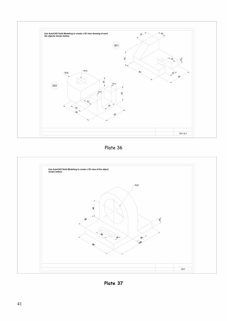
Use AutoCAD Solid Modeling to create a 3D view drawing of each the objects shown bellow.
80
6020
3020
40
15
20
60
15
15
80
30
Plate 36
90 120
45
45
30
15
30
15
R20
3D3
Use AutoCAD Solid Modeling to create a 3D view of the object shown bellow.
Plate 37

42
Use Solid Modeling to create a 3D view of each object shown below.
32
40
50
R6
6640
8
15
88
2012
22
18
R6
19 11
60
30
11
228
11
15
19
11
19
8
19
Plate38
4040
30
40
1020
10
4040
40
30
20
10
DRAW A SOLID MODEL OF EACH OBJECT FROM THE GIVEN ISOMETRIC VIEWS BELLOW.
10
10
10
10
20
10
10
Plate 39

43
APPENDICES

44
APPENDIX A
TYPES OF LINES IN ENGINEERING GRAPHICS
1 Dimension line: dark, thin and continuous.
2 Extension line: dark, thin and continuous.
3 Visible line: dark, thick and continuous.
4 Hidden line: Dark, medium and Dashed.
5 Center line: Dark, thin long dash and small dash.
6 Section line: Dark, Thin and Continuous.
7 Cutting Plane line: dark, thick long dash and small dash.

45
APPENDIX B
TYPES OF HOLES USED IN ENGINEERING GRAPHICS

46
APPENDIX C
AUTOCAD DRAWING AND EDITING COMMANDS
COORD- Function Key F6 will allow you to turn coordinates ON or OFF.
GRID- A matrix of dots that help you find your way around the
Screen. F7 key will turn the GRID ON or OFF.
SNAP- Will help you move on the screen to a predetermined point.
F9 Key turns the SNAP ON or OFF.
ORTHO- Will help you draw perpendicular lines. F8 key turns the
Orthogonal ON or OFF.
UNITS- Will allow you to select the units of measurement.
LAYERS- Will allow you to separate entities on your drawing.
LINE- L. Will allow you to draw lines.
POLYLINE- PL. Will allow you to draw a series of segments as one line.
PEDIT- Will allow you to edit a polyline.
OFFSET- Will allow you to create parallel lines.
ARCS- A. Will allow you to draw arcs.
CIRCLES- C. Will allow you to draw circles.
COPY- CO. Will allow to copy objects on the screen from one position to
another.
ARRAY- R. Rectangular array, it will allow you to create a matrix of
objects.
ARRAY- P. Polar array, it will allow you to create a circular array.

47
ROTATE- RO. Will allow you to rotate objects around a base point to
any angle.
MIRROR- Will allow you to mirror objects around a 90º axes.
MOVE- Will allow you to move objects within the screen.
BREAK- Will allow you to break a line into two entities.
EXTEND- Will allow you to extend a line to another graphic entity.
TRIM- Will allow you to shorten a line or a group of lines to their
intersections.
HATCH- Will allow you to place section lines using different patterns.
FILLET- Will allow you to convert sharp corners to round corners.
CHAMFER- Will allow you to cut sharp corners.
ERASE- E. Will allow you to delete any graphic entity from the screen

D. AUTOCAD FUNCTION KEYS
Keys Functions _______________________________________________________________________
F1. Help.
F2. Switches from Graphics mode to Text mode and vise versa.
F3. Turns Object Snap ON/OFF.
F6. Turns Coordinate read out ON/OFF.
F7. Turns Grid display ON/OFF.
F8. Turns Perpendicularity ON/OFF.
F9. Turns Snap ON/OFF.

E. DRAWING ASSIGNMENTS
Plates # Descriptions Pages #
Plate
1
Alphabet of lines 8
Plate
2
Different type of fonts and Text Styles 11
Plates
3 - 10
Orthographic Projections
Missing Views and 3View drawings
13 - 16
Plates
11 - 12
Geometric Construction 18
Plates
13 - 18
Sectional Views 21 - 23
Plates
19 - 23
Auxiliary Views 25 - 27
Plates
24 - 31
Surface Intersections 29 - 32
Plate
32 - 35
Pictorial Drawings 35 - 36
Plates
36 - 39
3D Drawings 41 - 42

2


![[PPT]CE 101 Engineering Drawing - İTÜweb.itu.edu.tr/~keceli/autocad/Orthographic_r1.ppt · Web viewTitle CE 101 Engineering Drawing Author Cem Cuneyt Ugur Last modified by yavuz](https://img.dokumen.tips/doc/110x75/5ad7441b7f8b9a991b8bd78a/pptce-101-engineering-drawing-itwebituedutrkeceliautocadorthographicr1pptweb.jpg)