Embed Size (px)
Citation preview

Engineering Fracture Mechanics 131 (2014) 687–701
Contents lists available at ScienceDirect
Engineering Fracture Mechanics
journal homepage: www.elsevier .com/locate /engfracmech
A fracture mechanics-based method for prediction of crackingof circular and elliptical concrete rings under restrainedshrinkage
http://dx.doi.org/10.1016/j.engfracmech.2014.10.0150013-7944/� 2014 The Authors. Published by Elsevier Ltd.This is an open access article under the CC BY license (http://creativecommons.org/licenses/by/3.0/).
⇑ Corresponding author.E-mail addresses: [email protected] (W. Dong), [email protected] (X. Zhou), [email protected] (Z. Wu).
Wei Dong a, Xiangming Zhou b,⇑, Zhimin Wu a
a State Key Laboratory of Coastal and Offshore Engineering, Dalian University of Technology, Dalian 116024, PR Chinab School of Engineering and Design, Brunel University, London UB8 3PH, UK
a r t i c l e i n f o a b s t r a c t
Article history:Received 23 March 2014Received in revised form 10 July 2014Accepted 8 October 2014Available online 16 October 2014
Keywords:Brittle fractureConcreteCrack initiationEnvironmental crackingR-curvesResidual stressesStress intensity factorTest standards
A new experimental method, utilizing elliptical ring specimens, is developed for assessingthe likelihood of cracking and cracking age of concrete subject to restrained shrinkage. Toinvestigate the mechanism of this new ring test, a fracture mechanics-based numericalapproach is proposed to predict crack initiation in restrained concrete rings by using theR-curve method. It has been found that numerical results accord well with experimentalresults in terms of cracking ages for both circular and elliptical concrete rings, indicatingthat the proposed fracture mechanics-based numerical approach is reliable for analyzingcracking in concrete ring specimens subject to restrained shrinkage.� 2014 The Authors. Published by Elsevier Ltd. This is an open access article under the CC
BY license (http://creativecommons.org/licenses/by/3.0/).
1. Introduction
When volume change of concrete from autogenous, drying or thermal shrinkage is restrained, residual stress will bedeveloped and crack may occur once the residual tensile stress exceeds the tensile strength of concrete. This shrinkage crack-ing is a major problem for flat concrete elements/structures with a large exposed surface area-to volume (A/V) ratio, such asindustrial floors, concrete pavements and bridge decks, in particular when concrete is at early ages. Cracking in concrete canreduce load carrying capacity and accelerate deterioration, which shortens the service life of concrete structures andincreases maintenance costs. Therefore, researchers are seeking to develop simple tests to assess how susceptible a concretemixture may be to cracking in decades. So far, such as the bar [1,2], the plate/slab [3,4] and the ring tests [5,6] have beendeveloped to evaluate the cracking tendency of concrete under restrained conditions. However, it has been found difficultiesin providing sufficient restraint in the bar and plate/slab tests [7]. On the other hand, the circular ring test has been widelyused for assessing cracking tendency of concrete and other cement-based materials [8,9] due to its simplicity and versatility.It has subsequently become a standard test method for assessing cracking potential of concrete and other cement-basedmaterials recommended by American Association of State Highway and Transport Officials (AASHTO) (i.e., AASHTO PP34-99: Standard Practice for Cracking Tendency using a Ring Specimen) and by American Society for Testing and Materials (ASTM)
Nomenclature
R critical energy release rate (fracture resistance)G crack driving energy rateR0 internal radius of a circular concrete ringRi external radius of a circular concrete ringR1 inner major radius of an elliptical concrete ringR2 inner minor radius of an elliptical concrete ringd wall thickness of a restraining steel ringE elastic modulusft splitting tensile strengthfc uniaxial compressive strengtht age of concreteKIC critical stress intensity factorCTODC critical crack tip opening displacementa crack lengthaf
c critical crack lengthw concrete ring wall thicknessr nominal stressT fictitious temperature dropac linear expansion coefficient of concreteac critical crack lengtha0 initial crack lengtha, b coefficients of R-curveecr(t,t0) stress–dependent strain at time trc(t0) stress in concrete at the time of loading t0
Eci(t0) elastic modulus of concrete at the time of loading t0
J(t,t0) creep functionu(t,t0) creep coefficientDrh increment of the circumferential tensile stress
688 W. Dong et al. / Engineering Fracture Mechanics 131 (2014) 687–701
(i.e., ASTM C1581/C1581M-09a: Standard Test Method for Determining Age at Cracking and Induced Tensile Stress Characteristicsof Mortar and Concrete under Restrained Shrinkage).
As a test method for assessing cracking potential of concrete, the ability of generating a visible crack within a short periodis desirable for large amount of assessment of cracking tendency of concretes or other cement-based materials. However, ithas been found that it may result in a fairly long period before the first cracking occurs in a restrained circular concrete ringdue to either the restraining steel core is not stiff enough or the concrete is characterized with high crack resistance [10,11].Besides, initial cracking may appear anywhere along the circumference of a circular ring specimen, making it difficult to bedetected or traced in experiment. Therefore, although standard dimensions of circular ring specimens are recommended byAASHTO and ASTM, respectively, many researchers have used circular ring specimens with other geometries [8,9,11–15].Meanwhile, a novel elliptical ring geometry was adopted for assessing cracking tendency of mortar under restrained condi-tion. In this initiative, the first cracking was expected to occur earlier than in a circular geometry to shorten experiment dura-tion. It was believed that there is higher stress intensity in an elliptical ring due to geometrical effect [16,17]. This initiativehas been recognized as an effort to increase the stress concentration provided by the ring by Moon and Weiss [14]. It shouldbe noted that, although it is generally regarded that higher degree of restraint can be provided by an elliptical geometry thana circular one in the restrained ring test, there is no evidence having been presented in scientific literature to validate this. Sofar, the researches related to elliptical concrete ring test [16–18] are focused on using elliptical ring test as a better tool thanthe circular ring test for estimating the cracking tendency of concrete or other cement-based materials. No much effort hasbeen made on exploring the mechanism of the elliptical ring test or validating the advantages of elliptical geometry over-whelming circular geometry in shortening ring test which is still not clear to concrete science and engineering community.
A few theoretical/numerical models have been proposed to predict residual stress development and cracking age of con-crete in restrained circular ring specimens. In a circular ring specimen, restraining effect from the central steel ring to thesurrounding concrete ring is uniform along its circumference. Consequently, uniform circumferential tensile stress isresulted in the concrete ring along its circumference. Therefore, the restraining effect from the central steel ring on surround-ing concrete can be conveniently replaced by a fictitious uniform pressure applied on the internal surface of the concrete ringin analytical/numerical analyses [11,12,19,20]. But, things are different in case of an elliptical geometry. The ellipticalgeometry produces a complicated and non-uniform circumferential stress in the elliptical concrete ring. Consequently, aclosed-form analytical solution is not available for predicting residual stress development in an elliptical concrete ring sub-ject to restrained shrinkage. Recently, Zhou et al. [21] conducted comparison test of a series of circular and elliptical concrete
X
Y
R0
R0
Steel RingConcrete Ring
d
R1
Steel RingConcrete Ring
R2
X
Y
d
(a) Circular ring (b) Elliptical ring
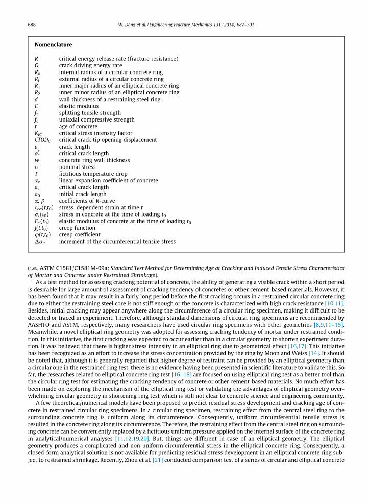
Fig. 1. Notation of geometrical parameters of circular and elliptical ring specimens.
W. Dong et al. / Engineering Fracture Mechanics 131 (2014) 687–701 689
rings and demonstrated the advantages of using elliptical rings over circular ones in faster and more reliable assessment ofcracking potential of concrete. They also proposed an elastic damage model based on maximum tensile stress cracking cri-terion for predicting crack initiation in circular and elliptical concrete rings under restrained shrinkage.
On the other hand, cracking criteria for concrete, which is generally regarded as a quasi-brittle material, can be a contro-versial issue in concrete science and engineering community. Although cracking of concrete can be determined based on theconventional maximum tensile stress cracking criterion, some researchers [8,15,23] have criticized that such a tensile stress-based failure criterion might not yield accurate results for cracking of concrete at early ages, and a fracture-based crackingcriterion tends to be more appropriate. In this case, the fracture resistance curve approach, which is based on fracturemechanics theory but is executed in the format of energy balance, has been widely used by many researches in analyzingcracking of concrete [8,15,19,22]. By comparing critical energy release rate (R-curve) and crack driving energy rate (G-curve),steady and unsteady crack propagation stages in concrete, as well as the critical moment of crack propagation evolving fromsteady to unsteady stage, can be determined. It should be noted that, the G-curve is closely related to the stress field around acrack in concrete and the shape and geometry of a concrete element. In the case of a restrained circular ring, the stress inconcrete can be conveniently calculated by using the fictitious uniform pressure to simulate the effect of shrinkage in con-crete. Stress intensity factor can also be approximately obtained by using a weighting function approach [23], in which R0/Ri
(R0 and Ri are internal and external radius of a circular concrete ring, respectively) was introduced as a sole characteristicparameter for determining the coefficients of the geometry function. However, the R-curve approach based on fracturemechanics cannot be directly employed for analyzing cracking in an elliptical concrete ring. Firstly, as aforementioned,the assumption of a uniform pressure between a concrete and a steel ring is not appropriate for simulating the effect ofshrinkage in an elliptical concrete ring due to the influence of its elliptical geometry. Secondly, compared with circular ringswhich are geometrically similar with geometry function depending on R0/Ri only, elliptical rings are much complicated. Theirgeometry function not only depends on their inner major radius-to-outer major radius ratio, i.e. R1/(R1 + d) with R1 and d (d isthe thickness of a steel ring) denoted in Fig. 1, but also the inner minor radius-to-outer minor radius ratio, i.e., R2/(R2 + d)with R2 denoted in Fig. 1, as well as the absolute values of the inner/outer major radiuses, i.e. R1 + d and R2 + d, and theinner/outer minor radiuses, i.e. R1 and R2. So far, there is neither geometry function of stress intensity factor having beenproposed for an elliptical ring, nor is the R-curve approach having been used to analyses cracking in a restrained ellipticalconcrete ring.
In line with these, a numerical approach was developed in this study to analyze fracture of concrete in restrained ringspecimens subject to drying from their outer circumferential cylindrical surface. A fictitious temperature field, which isderived based on free shrinkage test of concrete prisms, was applied on concrete ring specimens in numerical analyses tosimulate the mechanical effect of concrete shrinkage on rings under exposed condition. Secondly, a fracture-based failurecriterion is employed to determine crack occurrence in concrete rings subject to restrained shrinkage. It is found that crack-ing ages of both circular and elliptical rings, predicted by the proposed numerical approach, agree reasonably well withexperimental results, suggesting that the fracture-mechanics based numerical model, established in this research, is reliablefor analyzing cracking in restrained concrete ring specimens. It is expected that the fracture mechanics-based numericalmodel developed in this study will be helpful in exploring the mechanism of restrained elliptical concrete ring test whichcan be employed for assessing cracking tendency of concrete and other cement-based materials.
2. Experimental program
The mix proportions for the concrete used for this study was 1:1.5:1.5:0.5 (cement:sand:coarse aggregate:water) byweight with the maximum aggregate size of 10 mm. Concrete was prepared using a drum-type mixer and various concretespecimens were made including 100 mm-diameter and 200 mm-length cylinders for measuring mechanical properties of
690 W. Dong et al. / Engineering Fracture Mechanics 131 (2014) 687–701
concrete, 75 mm in square and 280 mm in length prisms for free shrinkage test, notched beams with the dimensions of100 � 100 � 500 mm3 for fracture test and a series of circular and elliptical ring specimens for restrained shrinkage test.Ready-mixed concrete was poured into relevant concrete moulds in layers and vibrated thoroughly after each layer of con-crete placement. Then the concrete specimens were covered by a layer of plastic sheet and cured in the normal laboratoryenvironment for 24 h. Subsequently, all specimens were de-moulded and moved into an environment chamber with 23 �Cand 50% relative humidity (RH) for continuous curing/drying. Mechanical properties of concrete, including elastic modulus E,splitting tensile strength ft and uniaxial compressive strength fc, were measured from the cylindrical specimens at 1, 3, 7, 14and 28 days, three specimens tested for each mechanical property at each age.
2.1. Material properties
It has been found that the average 28-day compressive and splitting tensile strength of the concrete are 27.21 and2.96 MPa, respectively, indicating that a normal strength concrete was prepared for this study. As aforementioned, onlymechanical properties of concrete at the ages of 1, 3, 7, 14 and 28 days were physically measured. Based on experimentalresults, regression analyses were conducted to obtain continuous equations that can estimate the age-dependent mechanicalproperties, in this case, E and ft, for the concrete. It was found that elastic modulus, E, in GPa of the concrete at early ages canbe predicted using Eq. (1).
Fig. 2
EðtÞ ¼ 0:0002t3 � 0:0134t2 þ 0:3693t þ 12:715 ðt 6 28Þ ð1Þ
Splitting tensile strength, ft, in MPa can be predicted using Eq. (2).
f tðtÞ ¼ 1:82t0:13 ðt 6 28Þ ð2Þ
In both equations, t is the age (unit: day) of concrete. The values of E and ft for concrete at other ages which were notdirectly measured can be obtained from Eqs. (1) and (2).
In this study, fracture properties, including the critical stress intensity factor KIC and the critical crack tip opening dis-placement CTODC, of concrete were derived based on the two-parameter fracture model (TPFM) recommended by RILEM[24] from experimental results of three-point bending tests of centrally notched beams, with the dimensions of100 � 100 � 500 mm3, the pre-crack length of 33.3 mm, and test span of 400 mm. All fracture tests were carried out undercrack mouth opening displacement (CMOD) control model using an Instron 2670 series crack opening displacement gaugewith a CMOD rate of 0.0075 mm/min. KIC and CTODC, at the ages of 1, 3, 7, 14 and 28 days, were calculated conforming toRILEM recommendation in this study. Based on the experimental results of KIC and CTODC at the ages of 1, 3, 7, 14 and28 days, regression analyses were conducted to obtain continuous equations for KIC and CTODC, respectively. It is found thatthe KIC in MPa mm1/2 and CTODC in mm of the concrete at early ages can be predicted as following:
KICðtÞ ¼ 3:92 lnðtÞ þ 12:6 ð3ÞCTODC ¼ �0:029t2 þ 1:62t þ 3:96 ð4Þ
In the above two equations, t is the age (unit: day) of concrete.
2.2. Free shrinkage tests
Free shrinkage of concrete was measured on concrete prisms with the dimensions of 280 mm in length and 75 mm squarein cross section, conforming to ISO 1920-8, subject to drying in the same environment condition as for curing concrete
0 5 10 15 20 25 30-500
-400
-300
-200
-100
0
Shrin
kage
Stra
in (μ
ε )
Age (days)
not sealed 2 sides sealed 3 sides sealed all sealed
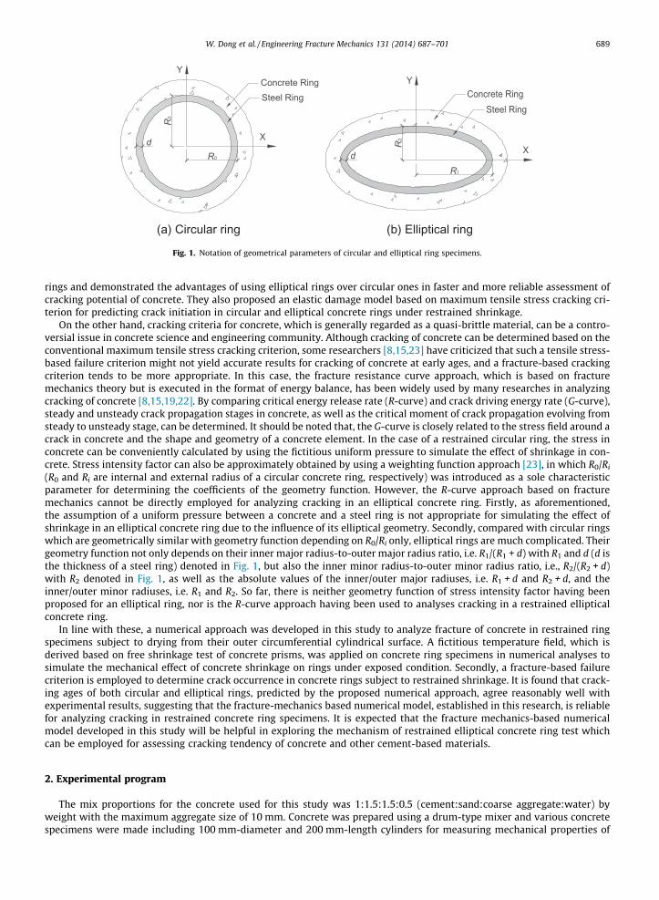
. Shrinkage strain of concrete obtained from free shrinkage test (note: side surface refers to the surface with the dimensions of 280 � 75 mm2).
(a) Circular ring (b) Elliptical ring I (c) Elliptical ring II
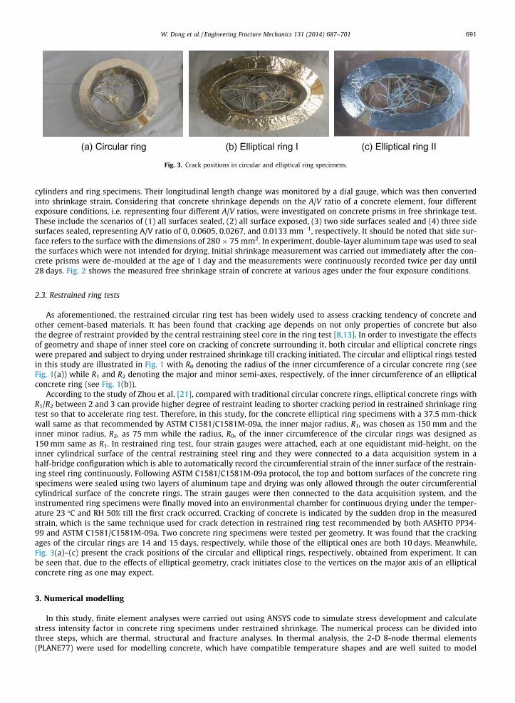
Fig. 3. Crack positions in circular and elliptical ring specimens.
W. Dong et al. / Engineering Fracture Mechanics 131 (2014) 687–701 691
cylinders and ring specimens. Their longitudinal length change was monitored by a dial gauge, which was then convertedinto shrinkage strain. Considering that concrete shrinkage depends on the A/V ratio of a concrete element, four differentexposure conditions, i.e. representing four different A/V ratios, were investigated on concrete prisms in free shrinkage test.These include the scenarios of (1) all surfaces sealed, (2) all surface exposed, (3) two side surfaces sealed and (4) three sidesurfaces sealed, representing A/V ratio of 0, 0.0605, 0.0267, and 0.0133 mm�1, respectively. It should be noted that side sur-face refers to the surface with the dimensions of 280 � 75 mm2. In experiment, double-layer aluminum tape was used to sealthe surfaces which were not intended for drying. Initial shrinkage measurement was carried out immediately after the con-crete prisms were de-moulded at the age of 1 day and the measurements were continuously recorded twice per day until28 days. Fig. 2 shows the measured free shrinkage strain of concrete at various ages under the four exposure conditions.
2.3. Restrained ring tests
As aforementioned, the restrained circular ring test has been widely used to assess cracking tendency of concrete andother cement-based materials. It has been found that cracking age depends on not only properties of concrete but alsothe degree of restraint provided by the central restraining steel core in the ring test [8,13]. In order to investigate the effectsof geometry and shape of inner steel core on cracking of concrete surrounding it, both circular and elliptical concrete ringswere prepared and subject to drying under restrained shrinkage till cracking initiated. The circular and elliptical rings testedin this study are illustrated in Fig. 1 with R0 denoting the radius of the inner circumference of a circular concrete ring (seeFig. 1(a)) while R1 and R2 denoting the major and minor semi-axes, respectively, of the inner circumference of an ellipticalconcrete ring (see Fig. 1(b)).
According to the study of Zhou et al. [21], compared with traditional circular concrete rings, elliptical concrete rings withR1/R2 between 2 and 3 can provide higher degree of restraint leading to shorter cracking period in restrained shrinkage ringtest so that to accelerate ring test. Therefore, in this study, for the concrete elliptical ring specimens with a 37.5 mm-thickwall same as that recommended by ASTM C1581/C1581M-09a, the inner major radius, R1, was chosen as 150 mm and theinner minor radius, R2, as 75 mm while the radius, R0, of the inner circumference of the circular rings was designed as150 mm same as R1. In restrained ring test, four strain gauges were attached, each at one equidistant mid-height, on theinner cylindrical surface of the central restraining steel ring and they were connected to a data acquisition system in ahalf-bridge configuration which is able to automatically record the circumferential strain of the inner surface of the restrain-ing steel ring continuously. Following ASTM C1581/C1581M-09a protocol, the top and bottom surfaces of the concrete ringspecimens were sealed using two layers of aluminum tape and drying was only allowed through the outer circumferentialcylindrical surface of the concrete rings. The strain gauges were then connected to the data acquisition system, and theinstrumented ring specimens were finally moved into an environmental chamber for continuous drying under the temper-ature 23 �C and RH 50% till the first crack occurred. Cracking of concrete is indicated by the sudden drop in the measuredstrain, which is the same technique used for crack detection in restrained ring test recommended by both AASHTO PP34-99 and ASTM C1581/C1581M-09a. Two concrete ring specimens were tested per geometry. It was found that the crackingages of the circular rings are 14 and 15 days, respectively, while those of the elliptical ones are both 10 days. Meanwhile,Fig. 3(a)–(c) present the crack positions of the circular and elliptical rings, respectively, obtained from experiment. It canbe seen that, due to the effects of elliptical geometry, crack initiates close to the vertices on the major axis of an ellipticalconcrete ring as one may expect.
3. Numerical modelling
In this study, finite element analyses were carried out using ANSYS code to simulate stress development and calculatestress intensity factor in concrete ring specimens under restrained shrinkage. The numerical process can be divided intothree steps, which are thermal, structural and fracture analyses. In thermal analysis, the 2-D 8-node thermal elements(PLANE77) were used for modelling concrete, which have compatible temperature shapes and are well suited to model

692 W. Dong et al. / Engineering Fracture Mechanics 131 (2014) 687–701
curved boundaries. Through thermal analysis, the temperature distribution in concrete can be achieved. In the followingstructural analysis, the elements for modelling concrete were replaced by the equivalent structural elements, i.e. PLANE183,which is a type of 2-D 8-node element with quadratic displacement behavior. PLANE183 elements are also well suited tomodelling irregular meshes and support plasticity, creep, stress stiffening, large deflection and large strain. In order to elim-inate the effect of friction between concrete and steel, the outer circumferential surface of the steel ring, which contacts theinner circumferential surface of the concrete ring, was coated with a release agent as suggested by ASTM C1581/C1581M-09a when preparing concrete ring tests. Accordingly, in numerical analyses, contact elements with zero friction betweenthe contacting pairs were utilized to simulate this measure in conducting concrete ring tests in practice. The material param-eters used in numerical analyses were as following: the elastic modulus and Poisson’s ratio of steel both remain constant as210 GPa and 0.3, respectively; the elastic modulus of concrete is determined using Eq. (1), which varies with age, and Pois-son’s ratio is set constant as 0.2. In fracture analysis, singular element was used to calculate SIF at crack tip. Because highstress gradients exist in the region around crack tip, special attention should be paid in that region. Therefore, a circlewas set at the tip of crack, in which the crack tip is the center of the circle and the radius of the circle is 2 mm. The firstrow of elements around the crack tip had a radius of 1/2 mm, and their mid-side nodes were placed at the quarter points,i.e. had a radius of 1/8 mm.
3.1. Modelling of restrained shrinkage
Compared with a circular steel core, an elliptical one can provide higher degree of restraint to concrete surrounding it andalso generate a non-uniform distribution of stress along its elliptical circumference when concrete is subject to dryingshrinkage. The geometry factor R1/R2 of an elliptical ring dominates the degree of stress concentration in concrete and sub-sequently influences cracking age and position. Therefore, the conventional uniform internal pressure assumption widelyadopted in analyzing restrained circular rings, which is used to simulate the effect of drying shrinkage, is not applicableto elliptical ones in restrained shrinkage test. In order to take into account the non-uniform stress distribution in ellipticalconcrete rings, a numerical approach was proposed to simulate the effect of geometry factor on cracking in concrete ringspecimens subject to drying shrinkage. In this approach, a derived fictitious temperature field is applied to concrete to sim-ulate the shrinkage effect so that a combined thermal and structural analysis can be adopted to analyze cracking in a con-crete ring specimen caused by restrained shrinkage. With the implementation of the fictitious temperature field, shrinkageof concrete caused by the temperature field is restrained by the inner steel core, resulting in compressive stress developed inthe steel core and tensile stress in the concrete ring. The derivation of the fictitious temperature field is elaborated elsewhere[21]. As the result of this exercise, Fig. 4 presents the derived relationship between fictitious temperature drop and A/V ratioat 3 days interval for a concrete element irrespective of its geometry/shape. For a given concrete ring with certain exposurecondition (i.e. certain A/V ratio), the relationship between fictitious temperature drop and concrete age can be derived bylinear interpolation from the relationship between A/V ratio and concrete age obtained in Fig. 4.
3.2. Crack driving energy rate curve (G-curve)
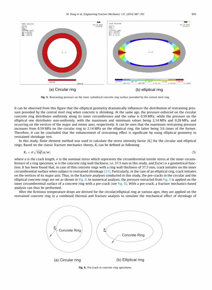
After the age-dependent fictitious temperature drop is determined, shrinkage effect can be simulated through applyingthe temperature drop on concrete in numerical analysis. When shrinkage of concrete is restrained by the inner steel ring,internal stress is developed in concrete, which is uniformly distributed in a circular ring but non-uniformly distributed inan elliptical ring. Fig. 5(a) and (b) present the restraining pressure on the inner circumferential concrete ring surfaceenforced by the central steel ring in a circular and an elliptical geometries, respectively, at the age of 10 days when con-crete is subject to restrained shrinkage (in Fig. 5(a) and (b) the grey ring represents the concrete ring, circular or elliptical).
0.00 0.01 0.02 0.03 0.04 0.05 0.06 0.07 0.08-50
-40
-30
-20
-10
0
Fict
itiou
s Te
mpe
ratu
re D
rop
(o C)
1 d 3 d 6 d 9 d 13 d 15 d 17 d 21 d 24 d 27 d
A/V (mm-1)
Fig. 4. Derived fictitious temperature drop with respect to A/V ratio for a concrete element.
(a) Circular ring (b) elliptical ring
Fig. 5. Restraining pressure on the inner cylindrical concrete ring surface provided by the central steel ring.
W. Dong et al. / Engineering Fracture Mechanics 131 (2014) 687–701 693
It can be observed from this figure that the elliptical geometry dramatically influences the distribution of restraining pres-sure provided by the central steel ring when concrete is shrinking. At the same age, the pressure enforced on the circularconcrete ring distributes uniformly along its inner circumference and the value is 0.59 MPa; while the pressure on theelliptical one distributes non-uniformly, with the maximum and minimum values being 2.14 MPa and 0.28 MPa, andoccurring on the vertices of the major and minor axes, respectively. It can be seen that the maximum restraining pressureincreases from 0.59 MPa on the circular ring to 2.14 MPa on the elliptical ring, the latter being 3.6 times of the former.Therefore, it can be concluded that the enhancement of restraining effect is significant by using elliptical geometry inrestrained shrinkage test.
In this study, finite element method was used to calculate the stress intensity factor (KI) for the circular and ellipticalrings. Based on the classic fracture mechanics theory, KI can be defined as following
KI ¼ rffiffiffiffiffiffiffiffipaf
pða=wÞ ð5Þ
where a is the crack length, r is the nominal stress which represents the circumferential tensile stress at the inner circum-ference of a ring specimen, w is the concrete ring wall thickness, i.e. 37.5 mm in this study, and f(a/w) is a geometrical func-tion. It has been found that, in case of thin concrete rings with a ring wall thickness of 37.5 mm, crack initiates on the innercircumferential surface when subject to restrained shrinkage [21]. Particularly, in the case of an elliptical ring, crack initiateson the vertices of its major axis. Thus, in the fracture analyses conducted in this study, the pre-cracks in the circular and theelliptical concrete rings are set as shown in Fig. 6. In numerical analysis, the pressure extracted from Fig. 5 is applied on theinner circumferential surface of a concrete ring with a pre-crack (see Fig. 6). With a pre-crack, a fracture mechanics-basedanalysis can thus be performed.
After the fictitious temperature drops are derived for the circular/elliptical ring at various ages, they are applied on therestrained concrete ring in a combined thermal and fracture analysis to simulate the mechanical effect of shrinkage of
Concrete Ringa
Concrete Ringa
(a) Circular ring (b) Elliptical ring
Fig. 6. Pre-crack in concrete ring specimens.
694 W. Dong et al. / Engineering Fracture Mechanics 131 (2014) 687–701
concrete. It is generally regarded that moisture gradient across a concrete section can influence shrinkage of concrete. Theassumption of uniform shrinkage across a concrete ring wall is acceptable when the influence of moisture gradient is lesssignificant [9,13], for example, in the case of a concrete ring specimen drying from its top and bottom surfaces in restrainedshrinkage test. Based on this assumption, crack initiates at the inner circumferential surface and propagates towards theouter one of a restrained concrete ring specimen. When the influence of moisture gradient becomes significant, the non-uni-form shrinkage across a concrete ring wall leads to higher tensile stress at the outer circumference than at the inner one of arestrained concrete ring. This subsequently results in crack initiating at the outer circumference [13], for instance, in the sce-nario that the ring specimens with a 75 mm thick wall drying from the outer circumference in restrained shrinkage test.However, comparing with the scenario of a thick concrete ring specimen with a 75 mm thick wall, the influence of moisturegradient on shrinkage of concrete is not significant in the case of a thin concrete ring specimen with the wall thickness of37.5 mm. In line with this, it is approximately assumed in this study that shrinkage of concrete is uniform across the wallof a 37.5 mm-thick concrete ring specimen. On the other hand, it was found that crack initiated at the inner circumferentialsurface in all thin ring specimens tested in this study, which verifies the uniform shrinkage assumption. Accordingly, in thisstudy the fictitious temperature field, simulating the effect of concrete shrinkage, was reasonably assumed uniform acrossthe wall of the thin concrete ring specimens with a 37.5 mm thick wall.
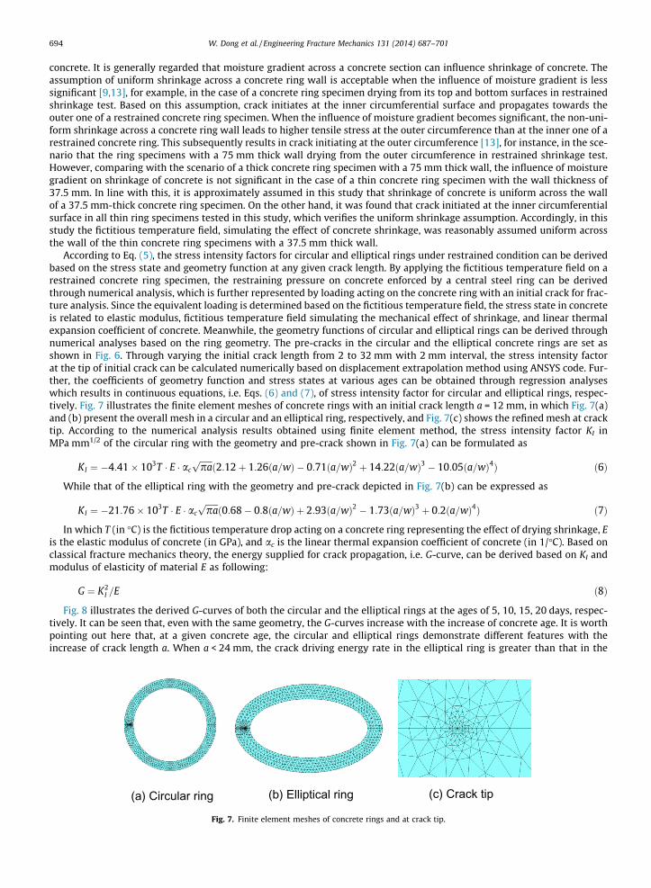
According to Eq. (5), the stress intensity factors for circular and elliptical rings under restrained condition can be derivedbased on the stress state and geometry function at any given crack length. By applying the fictitious temperature field on arestrained concrete ring specimen, the restraining pressure on concrete enforced by a central steel ring can be derivedthrough numerical analysis, which is further represented by loading acting on the concrete ring with an initial crack for frac-ture analysis. Since the equivalent loading is determined based on the fictitious temperature field, the stress state in concreteis related to elastic modulus, fictitious temperature field simulating the mechanical effect of shrinkage, and linear thermalexpansion coefficient of concrete. Meanwhile, the geometry functions of circular and elliptical rings can be derived throughnumerical analyses based on the ring geometry. The pre-cracks in the circular and the elliptical concrete rings are set asshown in Fig. 6. Through varying the initial crack length from 2 to 32 mm with 2 mm interval, the stress intensity factorat the tip of initial crack can be calculated numerically based on displacement extrapolation method using ANSYS code. Fur-ther, the coefficients of geometry function and stress states at various ages can be obtained through regression analyseswhich results in continuous equations, i.e. Eqs. (6) and (7), of stress intensity factor for circular and elliptical rings, respec-tively. Fig. 7 illustrates the finite element meshes of concrete rings with an initial crack length a = 12 mm, in which Fig. 7(a)and (b) present the overall mesh in a circular and an elliptical ring, respectively, and Fig. 7(c) shows the refined mesh at cracktip. According to the numerical analysis results obtained using finite element method, the stress intensity factor KI inMPa mm1/2 of the circular ring with the geometry and pre-crack shown in Fig. 7(a) can be formulated as
KI ¼ �4:41� 103T � E � ac
ffiffiffiffiffiffipap
ð2:12þ 1:26ða=wÞ � 0:71ða=wÞ2 þ 14:22ða=wÞ3 � 10:05ða=wÞ4Þ ð6Þ
While that of the elliptical ring with the geometry and pre-crack depicted in Fig. 7(b) can be expressed as
KI ¼ �21:76� 103T � E � ac
ffiffiffiffiffiffipap
ð0:68� 0:8ða=wÞ þ 2:93ða=wÞ2 � 1:73ða=wÞ3 þ 0:2ða=wÞ4Þ ð7Þ
In which T (in �C) is the fictitious temperature drop acting on a concrete ring representing the effect of drying shrinkage, Eis the elastic modulus of concrete (in GPa), and ac is the linear thermal expansion coefficient of concrete (in 1/�C). Based onclassical fracture mechanics theory, the energy supplied for crack propagation, i.e. G-curve, can be derived based on KI andmodulus of elasticity of material E as following:
G ¼ K2I =E ð8Þ
Fig. 8 illustrates the derived G-curves of both the circular and the elliptical rings at the ages of 5, 10, 15, 20 days, respec-tively. It can be seen that, even with the same geometry, the G-curves increase with the increase of concrete age. It is worthpointing out here that, at a given concrete age, the circular and elliptical rings demonstrate different features with theincrease of crack length a. When a < 24 mm, the crack driving energy rate in the elliptical ring is greater than that in the
(a) Circular ring (b) Elliptical ring (c) Crack tip
Fig. 7. Finite element meshes of concrete rings and at crack tip.

0 5 10 15 20 25 30 35
0.0
0.2
0.4
0.6
0.8
1.0
1.2
1.4
Ener
gy re
leas
e ra
te (N
/mm
)
Crack length (mm)
Circular 5 days Circular 10 days Circular 15 days Circular 20 days Elliptical 5 days Elliptical 10 days Elliptical 15 days Elliptical 20 days
Fig. 8. G-curves of circular and elliptical rings at various ages.
W. Dong et al. / Engineering Fracture Mechanics 131 (2014) 687–701 695
circular ring, indicating that the elliptical ring may crack earlier than the circular one if the critical crack length is less than24 mm. However, when a > 24 mm, the crack driving energy rate in the circular ring is greater than that in the elliptical ring,suggesting that the circular ring may crack earlier than the elliptical one if the critical crack length is greater than 24 mm.
3.3. Resistance curve (R-Curve)
The resistance curve (R-Curve) method presented here is based on the work of Ouyang and Shah [25] and Shah et al. [19]for investigating crack propagation in concrete. The R-curve is formulated as
R ¼ bwða� a0Þd2 ð9Þ
d1;2 ¼12þ a� 1
a� 1
4þ a� 1
a� a� 1
a
� �2" #1
2
ð10Þ
w ¼ 1� ðd2a� aþ 1Þðd1a� aþ 1Þ
aa0 � a0
a� a0
� �d2�d1
ð11Þ
where a = ac/a0, ac is the critical crack length and a0 is the initial crack length. In order to obtain reasonable results for anuncracked concrete specimen, like the circular or elliptical concrete rings investigated in this study through fracture analy-ses, the initial crack length should remain reasonably as small as possible by considering the sizes of aggregates. In theresearch of Ouyang and Shah [25], initial crack length was chosen as 2 mm for concrete elements. As long as this valueremains reasonably small, it has been found that the overall fracture analysis results on the same concrete elements but withdifferent initial crack lengths are very close by using the R-curve method. Therefore, in order to reduce the effects of arbi-trariness of a0 on fracture analysis results of an actually un-cracked concrete ring specimen, a0 should be reasonably as smallas possible, which was chosen as 2 mm in this study for both the circular and the elliptical concrete rings. Moreover, for thedetermination of parameters a and b, Shah et al. [19] developed an expression (see Eq. (12)) based on an infinitely large platewith a single edge-notch (SEN) pre-crack under tensile loading as following. Firstly, stress intensity factor (KIC) and criticalcrack tip opening displacement (CTODc) can be derived numerically. Then, an expression can be obtained by substitutingCTODc into KIC, which is presented as following
0:117CTOD2c E2
ðKICÞ2a0
¼ a 1� 1a2
� �1� 0:5
aþ 0:434
a2 � 0:154a3
� �2
ð12Þ
Once CTODc and KIC, which are two fracture parameters of concrete, are derived from three-point bending test results ofnotched beams conforming to the recommendation of RILEM on TPFM, a can be determined using Eq. (12). Further, b isobtained by satisfying the equation of R ¼ K2
I =E, which can be expressed as
b ¼ ðKICÞ2ðaa0 � a0Þ�d2
E 1� d2a�aþ1d1a�aþ1
� � ð13Þ
It should be noted that the R-curve derived from Eqs. (9)–(13) is based on the geometry of an infinitely large plate. How-ever, according to Ouyang and Shah [25], for the same geometry and initial crack length, the derived R-curve also applies tofinite size specimens. R-curve is defined as an envelope of G-curves with different specimen sizes but the same initial crack
0 1 2 t Age
σθ
σθ(1) 3
σθ(2)
σθ(3)
σθ(t)
Fig. 9. Illustration of creep estimation in numerical analysis.
696 W. Dong et al. / Engineering Fracture Mechanics 131 (2014) 687–701
length [25]. Weiss et al. [8] have verified that the R-curves for circular ring specimens with different characteristic sizes butthe same initial crack length are similar to that of an infinitely large plate. Therefore, in this study the R-curves for the cir-cular and elliptical rings were approximately taken as that of an infinite large plate with a SEN pre-crack.
3.4. Creep
Since the derivation of fictitious temperature drop is based on volume change of concrete prisms subject to free shrinkagetest, the effect of creep on strain in a ring specimen is not taken into account when using the fictitious temperature drop to
0.0
0.4
0.8
1.2
1.6
2.0
2.4
2.8
Nom
inal
stre
ss (M
Pa)
Age (days)
stress without creep effect stress with creep effect
(a) Circular ring
0 2 4 6 8 10 12 14 16 18 20
0 2 4 6 8 10 12 14 16 180.0
1.5
3.0
4.5
6.0
7.5
9.0
10.5
12.0
Nom
inal
stre
ss (M
Pa)
Age (days)
Stress with creep effect Stress without creep effect
(b) Elliptical ring
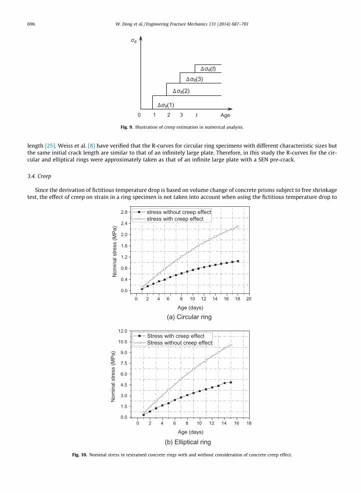
Fig. 10. Nominal stress in restrained concrete rings with and without consideration of concrete creep effect.

W. Dong et al. / Engineering Fracture Mechanics 131 (2014) 687–701 697
simulate the shrinkage effect of concrete. But actually cracking of a concrete ring specimen is affected by not only shrinkagebut also creep, two unique material properties of concrete which not many other engineering materials possess one or bothof them. Therefore, it is significant to estimate the magnitude of creep during the process of restrained shrinkage in concrete.In this study creep of concrete is estimated using the formula recommended by CEB-FIP Model Code 2010, in which the totalstrain is the sum of elastic strain and creep strain and can be expressed as
ecrðt; t0Þ ¼ rcðt0Þ1
Eciðt0Þþuðt; t0Þ
Eci
� �¼ rcðt0ÞJðt; t0Þ ð14Þ
where ecr(t,t0) is the stress-dependent strain of concrete at time t, rc(t0) is the stress in concrete at the time of loading t0,Eci(t0) is the modulus of elasticity of concrete at the time of loading t0, Eci is the modulus of elasticity of concrete at theage of 28 days, J(t,t0) is the creep function, and u(t,t0) is the creep coefficient. Details for obtaining these parameters canbe referenced to CEB-FIP Model Code 2010. Since ecr(t,t0) depends on the circumferential tensile stress of a concrete ringunder restrained shrinkage, the stress can be divided into many increments Drh, which is caused by shrinkage of concreteincreasing with age. For example, when investigating the effects of creep at 10th day, the stress increment Drh(1) caused byshrinkage at the first day will affect that at the following 10 days, and the stress increment Drh(2) caused by shrinkage at thesecond day will only affect that of the following 9 days. This process is schematically illustrated in Fig. 9. After taking intoaccount the creep effect of concrete, the nominal stress in the circular and elliptical rings was calculated and presented inFig. 10(a) and (b), respectively. The nominal stress, without the consideration of concrete creep, in the circular and ellipticalrings was also presented for comparison purpose in Fig. 10. It can be seen that, with the consideration of creep, the nominalstress in both circular and elliptical concrete rings become much smaller as expected.
0 2 4 6 8 10 12 140.0
0.2
0.4
0.6
0.8
1.0
1.2
1.4
1.6
Allo
wab
le n
omin
al s
tress
(MPa
)
Crack length (mm)
(a,σmax)
(a) Circular ring
0 2 4 6 8 10 12 14 16 180
3
6
9
12
15
18
21 (a,σmax)
Allo
wab
le n
omin
al s
tress
(MPa
)
Crack length (mm)
(b) Elliptical ring
Fig. 11. Allowable nominal stress in concrete rings from fracture analysis.
698 W. Dong et al. / Engineering Fracture Mechanics 131 (2014) 687–701
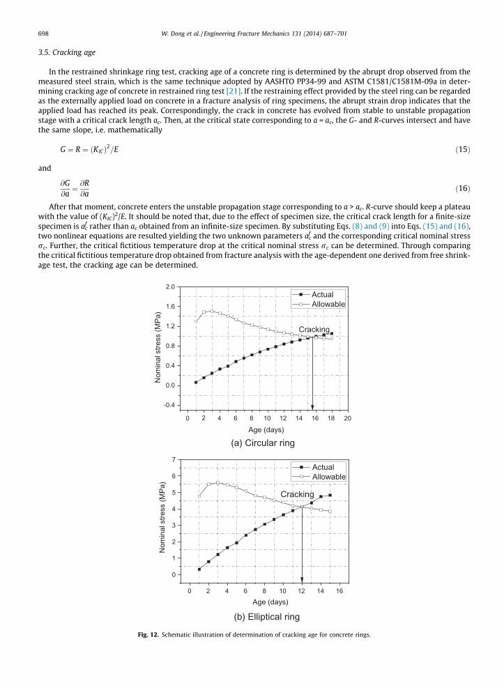
3.5. Cracking age
In the restrained shrinkage ring test, cracking age of a concrete ring is determined by the abrupt drop observed from themeasured steel strain, which is the same technique adopted by AASHTO PP34-99 and ASTM C1581/C1581M-09a in deter-mining cracking age of concrete in restrained ring test [21]. If the restraining effect provided by the steel ring can be regardedas the externally applied load on concrete in a fracture analysis of ring specimens, the abrupt strain drop indicates that theapplied load has reached its peak. Correspondingly, the crack in concrete has evolved from stable to unstable propagationstage with a critical crack length ac. Then, at the critical state corresponding to a = ac, the G- and R-curves intersect and havethe same slope, i.e. mathematically
G ¼ R ¼ ðKICÞ2=E ð15Þ
and
@G@a¼ @R@a
ð16Þ
After that moment, concrete enters the unstable propagation stage corresponding to a > ac. R-curve should keep a plateauwith the value of (KIC)2/E. It should be noted that, due to the effect of specimen size, the critical crack length for a finite-sizespecimen is af
c rather than ac obtained from an infinite-size specimen. By substituting Eqs. (8) and (9) into Eqs. (15) and (16),two nonlinear equations are resulted yielding the two unknown parameters af
c and the corresponding critical nominal stressrc. Further, the critical fictitious temperature drop at the critical nominal stress rc can be determined. Through comparingthe critical fictitious temperature drop obtained from fracture analysis with the age-dependent one derived from free shrink-age test, the cracking age can be determined.
0 2 4 6 8 10 12 14 16 18 20
-0.4
0.0
0.4
0.8
1.2
1.6
2.0
Nom
inal
stre
ss (M
Pa)
Age (days)
Actual Allowable
Cracking
(a) Circular ring
0 2 4 6 8 10 12 14 16
0
1
2
3
4
5
6
7
Nom
inal
stre
ss (M
Pa)
Age (days)
Actual Allowable
Cracking
(b) Elliptical ring
Fig. 12. Schematic illustration of determination of cracking age for concrete rings.
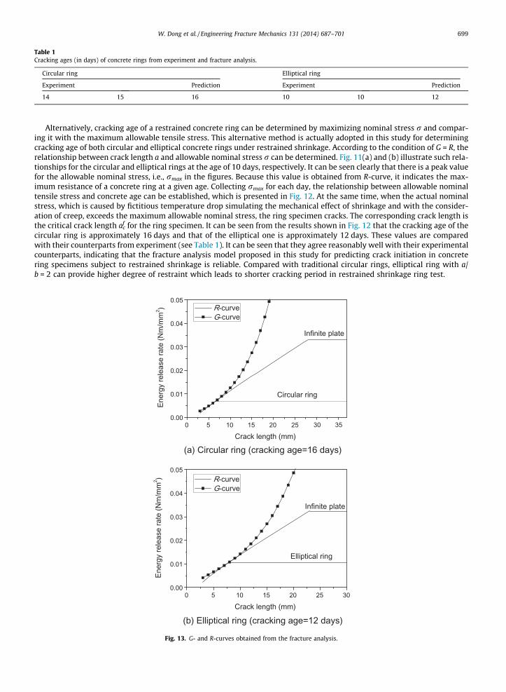
Table 1Cracking ages (in days) of concrete rings from experiment and fracture analysis.
Circular ring Elliptical ring
Experiment Prediction Experiment Prediction
14 15 16 10 10 12
W. Dong et al. / Engineering Fracture Mechanics 131 (2014) 687–701 699
Alternatively, cracking age of a restrained concrete ring can be determined by maximizing nominal stress r and compar-ing it with the maximum allowable tensile stress. This alternative method is actually adopted in this study for determiningcracking age of both circular and elliptical concrete rings under restrained shrinkage. According to the condition of G = R, therelationship between crack length a and allowable nominal stress r can be determined. Fig. 11(a) and (b) illustrate such rela-tionships for the circular and elliptical rings at the age of 10 days, respectively. It can be seen clearly that there is a peak valuefor the allowable nominal stress, i.e., rmax in the figures. Because this value is obtained from R-curve, it indicates the max-imum resistance of a concrete ring at a given age. Collecting rmax for each day, the relationship between allowable nominaltensile stress and concrete age can be established, which is presented in Fig. 12. At the same time, when the actual nominalstress, which is caused by fictitious temperature drop simulating the mechanical effect of shrinkage and with the consider-ation of creep, exceeds the maximum allowable nominal stress, the ring specimen cracks. The corresponding crack length isthe critical crack length af
c for the ring specimen. It can be seen from the results shown in Fig. 12 that the cracking age of thecircular ring is approximately 16 days and that of the elliptical one is approximately 12 days. These values are comparedwith their counterparts from experiment (see Table 1). It can be seen that they agree reasonably well with their experimentalcounterparts, indicating that the fracture analysis model proposed in this study for predicting crack initiation in concretering specimens subject to restrained shrinkage is reliable. Compared with traditional circular rings, elliptical ring with a/b = 2 can provide higher degree of restraint which leads to shorter cracking period in restrained shrinkage ring test.
0.00
0.01
0.02
0.03
0.04
0.05
Infinite plate
Circular ring
Ener
gy re
leas
e ra
te (N
m/m
m2 )
Crack length (mm)
R-curveG-curve
(a) Circular ring (cracking age=16 days)
0 5 10 15 20 25 30 35
0 5 10 15 20 25 300.00
0.01
0.02
0.03
0.04
0.05
Elliptical ring
Ener
gy re
leas
e ra
te (N
m/m
m2 )
Crack length (mm)
R-curveG-curve
Infinite plate
(b) Elliptical ring (cracking age=12 days)
Fig. 13. G- and R-curves obtained from the fracture analysis.

700 W. Dong et al. / Engineering Fracture Mechanics 131 (2014) 687–701
Based on the cracking age derived from Fig. 12, the G- and R-curves for circular and elliptical rings are illustrated inFig. 13(a) and (b), respectively. At the cracking ages, G- and R-curves intersect and also have the same slope. The crack lengthcorresponding to the point of intersection is the critical crack length af
c for a ring specimen. After this point, the R-curvereaches a plateau while G-curve keeps increasing overwhelming the R-curve, indicating fracture failure of the ring specimen.
4. Conclusions
A numerical approach based on fracture mechanics has been developed for predicting concrete cracking in restrained cir-cular and elliptical ring specimens subject to drying shrinkage. Ring specimens are widely used for assessing cracking ten-dency of concrete and other cement-based materials with the circular ring test has become a standard methodrecommended by both AASHTO and ASTM. The derived fictitious temperature field was used to simulate the effect of shrink-age in circular and elliptical ring specimens. The driving energy for crack propagation in a ring specimen can be determinednumerically while the resistance to crack propagation can also be derived based on measured fracture parameters of con-crete. Cracking age of restrained concrete rings can be determined by comparing the G- and R-curves. The following conclu-sions can be drawn:
(a) Cracking ages from numerical analyses agreed well with experimental results for circular and elliptical ring speci-mens. It indicates that using a fictitious temperature field to simulate the shrinkage of concrete and introducing resis-tance curve to investigate the cracking behavior of concrete in restrained shrinkage test are appropriate and reliable.
(b) Based on experimental and numerical results, it can be seen that the elliptical ring with R1/R2 = 2 cracks earlier thanthe circular ring, which can shorten the cracking period in restrained shrinkage ring test. The numerical results indi-cate that restraining pressure caused by shrinkage enforced on a circular concrete ring distributes uniformly along itscircumference, while that on an elliptical one distributes non-uniformly. Due to geometry effect, the maximum cir-cumferential tensile stress in an elliptical ring is about 3.6 times of that in a circular ring, which promotes markedlythe restraint effect on concrete in restrained shrinkage test.
(c) According to the evolution of crack driving energy rate, in addition to the geometry effect, it is the critical crack lengthaf
c corresponding to unstable cracking propagation which determines the advantage of using elliptical geometry inrestrained ring test to shorten test duration. For the normal strength concrete investigated in this research, whenaf
c < 24 mm, the driving energy in an elliptical ring is greater than that in a circular ring indicating that elliptical geom-etry can provide higher degree of restraint. In contrast, when af
c > 24 mm, things are different. The driving energy in anelliptical ring becomes less than that in a circular ring, indicating that an elliptical ring needs a longer period to crack.
Acknowledgments
The financial support of the UK Engineering and Physical Sciences Research Council under the grant of EP/I031952/1, andthe National Natural Science Foundation of China under the grant of NSFC 51121005/51109026 is gratefully acknowledged.
References
[1] Parilee AM, Buil M, Serrano JJ. Effect of fiber addition on the autogenous shrinkage of silica fume concrete. ACI Mater J 1989;86(2):139–44.[2] Kovler K. Testing system for determining the mechanical behavior of early age concrete under restrained and free uniaxial shrinkage. RILEM Mater
Struct 1994;27(6):324–30.[3] Kraai PP. A proposed test to determine the cracking potential due to drying shrinkage of concrete. Concr Construct 1985;30(9):775–8.[4] Shales CA, Hover KC. Influence of mix-proportion and construction operations on plastic shrinkage cracking in thin slabs. ACI Mater J
1988;85(6):495–504.[5] Carlson RC, Reading TJ. Model of studying shrinkage cracking in concrete building wall. ACI Struct J 1998;85(4):395–404.[6] Grzybowski M, Shah SP. Shrinkage cracking of fiber reinforced concrete. ACI Mater J 1990;87(2):138–48.[7] Weiss WJ. Prediction of early-age shrinkage cracking in concrete. Ph.D Dissertation, Northwestern University, Evanston, Illinois; 1999.[8] Weiss WJ, Yang W, Shah SP. Influence of specimen size/geometry on shrinkage cracking of rings. ASCE J Engng Mech 2000;126(1):93–101.[9] Weiss WJ, Shah SP. Restrained shrinkage cracking: the role of shrinkage reducing admixtures and specimen geometry. RILEM Mater Struct
2002;35(3):85–91.[10] Bentur A, Kovler K. Evaluation of early age cracking characteristics in cementitious systems. RILEM Mater Struct 2003;36(3):183–90.[11] Moon JH, Pease B, Weiss J. Quantifying the influence of specimen geometry on the results of the restrained ring test. J ASTM Int 2006;3(8):1–14.[12] Hossain AB, Weiss J. Assessing residual stress development and stress relaxation in restrained concrete ring specimens. Cem Concr Comp
2004;26(5):531–40.[13] Hossain AB, Weiss J. The role of specimen geometry and boundary conditions on stress development and cracking in the restrained ring test. Cem
Concr Res 2006;36(1):189–99.[14] Moon JH, Weiss J. Estimating residual stress in the restrained ring test under circumferential drying. Cem Concr Comp 2006;28(5):486–96.[15] Passuello A, Moriconi G, Shah SP. Cracking behavior of concrete with shrinkage reducing admixtures and PVA fibers. Cem Concr Comp
2009;31(10):699–704.[16] He Z, Zhou XM, Li ZJ. New experimental method for studying early-age cracking of cement-based materials. ACI Mater J 2004;101(1):50–6.[17] He Z, Li ZJ. Influence of alkali on restrained shrinkage behavior of cement-based materials. Cem Concr Res 2005;35(3):457–63.[18] He Z, Li ZJ, Chen MZ, Liang WQ. Properties of shrinkage-reducing admixture-modified pastes and mortar. RILEM Mater Struct 2006;39(4):445–53.[19] Shah SP, Ouyang C, Marikunte S, Yang W, Becq-Giraudon EA. A method to predict shrinkage cracking of concrete. ACI Mater J 1998;95(4):339–46.[20] Shah HR, Weiss WJ. Quantifying shrinkage cracking in fiber reinforced concrete using the ring test. RILEM Mater Struct 2006;39(9):887–99.

W. Dong et al. / Engineering Fracture Mechanics 131 (2014) 687–701 701
[21] Zhou XM, Dong W, Oladiran O. Assessment of restrained shrinkage cracking of concrete using elliptical ring specimens: experimental and numerical.ASCE J Mater Civ Engng 2014. http://dx.doi.org/10.1061/(ASCE) MT. 1943-5533.000100.
[22] Turcry P, Loukili A, Haidar K, Pijaudier CG, Belarbi A. Cracking tendency of self-compacting concrete subjected to restrained shrinkage: experimentalstudy and modeling. J Mater Civ Engng 2006;18(1):46–54.
[23] Wu XR, Carlson AJ. Weight function and stress intensity factors. Pergamon, Tarrytown, N.J; 1990.[24] Shah SP. RILEM committee on fracture mechanics of concrete-test methods, determination of the fracture parameters (Ks
Ic and CTODc) of plain concreteusing three-point bend tests. RILEM Mater Struct 1990;23(6):457–60.
[25] Ouyang CS, Shah SP. Geometry-dependent R-curve for quasi-brittle materials. J Am Ceram Soc 1991;74(11):2831–6.