Embed Size (px)
Citation preview
west virginia department of environmental protection
Division of Air Quality601 57 Street, SEth
Charleston, WV 25304Phone: (304) 926-0475 • Fax: (304) 926-0479
Earl Ray Tomblin, GovernorRandy C. Huffman, Cabinet Secretary
www.dep.wv.gov
ENGINEERING EVALUATION / FACT SHEET
BACKGROUND INFORMATION
Application No.: R13-3269Plant ID No.: 017-00158Applicant: EQT Gathering, LLCFacility Name: Janus Compressor StationLocation: Near West Union, Doddridge CountySIC/NAICS Code: 1311/211111Application Type: ConstructionReceived Date: August 28, 2015Engineer Assigned: Joe KesslerFee Amount: $4,500Date Received: September 9, 2015Complete Date: September 24, 2015Due Date: December 23, 2015Applicant's Ad Date: September 8, 2015Newspaper: The Herald RecordUTM’s: 516.767 km Easting • 4,345.400 km Northing • Zone 17Latitude/Longitude: 39.25777/-80.80566Description: Construction of a natural gas compressor station.
DESCRIPTION OF PROCESS
EQT Gathering, LLC (EQT) is proposing to construct a natural gas compressor station to belocated approximately 3.1 miles south-southwest of West Union, WV east of County Route (CR)11 (Arnold’s Creek Road). The proposed Janus Compressor Station will consist of four (4)Caterpillar G3616 4-Stroke Lean Burn (4SLB) 5,350 horsepower (hp) compressor engines, five (5)Capstone C200 NG 200kWe Microturbines, two (2) Exterran 125 mmscf/day triethylene glycol(TEG) dehydration units (GDUs), two (2) fuel gas heaters (1.15 and 0.77 mmBtu/hr), and two (2)8,820 gallon produced liquid storage tanks.
Natural gas produced in area wells will enter into the facility and will be compressed by theengines (ENG-001 through ENG-004). The compressed gas is sent and through the GDUs (DEHY-
Promoting a healthy environment.

001 and DEHY-002) where it is dehydrated to the desired level. The compressor engines are eachcontrolled (CO, VOCs, and formaldehyde) by an EMIT Technologies EBX-9000-3036F-8C4E-48Coxidation catalyst (C1 through C4).
Glycol dehydration is a liquid desiccant system used for the removal of water from naturalgas. In each GDU, lean, water-free glycol is fed to the top of an absorber (known as a "contactor")where it is contacted with the wet natural gas stream. The glycol removes water from the natural gasby physical absorption and is carried out the bottom of the column. The dry natural gas leaves thetop of the absorption column and is fed into a pipeline for transportation. The dehydrator still ventgases are each sent an associated enclosed flare (FLARE-001 and FLARE-002) for destruction. Additionally, each GDU contains several TEG storage tanks. However, the storage tanks are definedas de minimis sources under Table 45-13B of 45CSR13 as they are each less than 10,000 gallons andTEG has an extremely low vapor pressure (<0.01 mm Hg).
After leaving the absorber, each glycol stream - now referred to as “rich” glycol - is fed toa flash vessel where flashed hydrocarbon vapors are either sent to the reboiler as fuel or, if thereboiler is not in operation, sent to the associated enclosed flare. Any liquid hydrocarbons removedin the flash tank are sent to one of the 8,820 gallon produced liquid storage tanks (T-001 and T-002). Vapors from the produced liquids storage tanks (working/breathing/flashing) are sent to anassociated enclosed flare (FLARE-003).
After leaving the flash vessel, in each unit, the rich glycol is fed to a Glycol RegeneratorColumn. Each Regenerator Column consists of a column, an overhead condenser, and the reboiler.The glycol is thermally regenerated to remove excess water and regain high purity. The heat for theregeneration is provided by two (2) 2.31 mmBtu/hr natural gas-fired reboilers (RB-001 and RB-002). The hot, lean glycol is cooled by a heat-exchanger and is then fed to a pump where it is sent to theglycol absorber for reuse. Liquids produced in the regeneration process are sent to one of the facilitystorage tanks.
A portion of the gas is withdrawn after dehydration but before the station outlet metering andsent to the fuel gas system. The fuel gas is directed through a fuel gas scrubber and metering beforebeing directed to the compressor engines and other gas-powered equipment. Two (2) fuel gasheaters (HTR-1 and HTR-2) will be used in the fuel gas system to prevent the formation of hydratesand to minimize condensate dropout from the pressure reduction.
There are many other small storage tanks proposed for the facility (T-003 through T-024)used for bulk storage (lube oil storage, compressor oil storage, TEG storage, etc.). Any emissionsfrom the miscellaneous tanks are, based on the vapor pressures of the materials stored, consideredinsignificant. Additionally, the proposed facility will utilize an uncontrolled truck loadout (L1) toremove condensate and produced water from the site (estimated to be a maximum of 210,000gallons/year). Five (5) 200 kWe uncontrolled Microturbines (EG-001 through EG-005) will be usedto produce primary power for the facility.
SITE INSPECTION
On November 18, 2015, the writer conducted an inspection of the proposed location of theJanus Compressor Station. The proposed Janus site is located in a rural area of Doddridge County
Fact Sheet R13-3269EQT Gathering, LLC
Page 2 of 14 Janus Compressor Station

approximately 3.1 miles south-southwest of West Union, WV east of County Route (CR) 11(Arnold’s Creek Road). The writer was accompanied on the inspection by Mr. Alex Bosiljevac,Environmental Coordinator with EQT. Observations from the inspection include:
! The proposed facility will lie atop a hill approximately 3.1 miles south-southwest of WestUnion, WV east of County Route (CR) 11 (Arnold’s Creek Road). The area is rural in naturewith scattered homes and farms within several miles of the proposed location. Much naturalgas construction activity (pipelines, well-heads, etc.) is located in the County;
! At the time of the inspection, EQT was in the process of improving an access road to the topof the hill where the compressor station will sit and doing extensive landscaping work at theproposed site. No emission units were seen on the property; and
! The occupied dwelling located nearest to the proposed site is approximately 0.50 milesnorthwest of the proposed site on a hillside near CR 11/4 (Left Fork Run Road). Apreviously occupied home near the beginning of the access road to the site was in the processof being demolished.
The following is a picture of the proposed site of the Janus Compressor Station taken on theday of the inspection:
Fact Sheet R13-3269EQT Gathering, LLC
Page 3 of 14 Janus Compressor Station

Directions: [Latitude: 39.25777, Longitude: -80.80566] From the intersection of United States (US)Route 50 and CR 11 (Arnold’s Creek Road), travel south on CR 11 for approximately 0.7 miles andthen turn left onto CR 11/4 (Left Fork Run Road) - this road was unmarked at the time of inspection. Follow the CR 11/4 for approximately 1.1 miles to the facility access road on the right. Thecompressor station is located at the end of the access road atop the hill.
AIR EMISSIONS AND CALCULATION METHODOLOGIES
EQT included in Attachment N of the permit application air emissions calculations for theequipment and processes at the Janus Compressor Station. The following will summarize thecalculation methodologies used by EQT to calculate the potential-to-emit (PTE) of the proposedfacility.
Compressor Engines
Potential emissions from each of the four (4) Caterpillar G3616 4SLB 5,350 hp compressorengines (ENG-001 through ENG-004) were based on post-control emission factors provided by theoxidation catalyst vendor, the engine vendor, and as given in AP-42, Section 3.2 (AP-42 is adatabase of emission factors maintained by USEPA). Hourly emissions were based on the (ascalculated using a fuel heat rating of 7,338 Btu/hp-hr) maximum design heat input (MDHI) of theengines of 39.43 mmBtu/hr and the maximum hp rating. Annual emissions were based on 8,760hours of operation per year. The following table details the PTE of each compressor engine:
Table 1: Per-Compressor Engine PTE
Pollutant Emission Factor SourceHourly
(lb/hr)
Annual
(ton/yr)
CO 0.1729 g/hp-hr (controlled) Catalyst Vendor 2.04 8.93(1)
XNO 0.50 g/hp-hr Engine Vendor 5.90 25.83
2.5 10PM /PM /PM 9.91 x 10 lb/mmBtu AP-42, Table 3.2-2 0.39 1.71(2) -3
2SO 5.88 x 10 lb/mmBtu AP-42, Table 3.2-2 0.02 0.10-4
VOCs 0.3335 g/hp-hr (controlled) Catalyst Vendor 3.93 17.23(1)
Total HAPs Various AP-42, Table 3.2-2 1.00 4.38
Formaldehyde 0.02 g/hp-hr (controlled) Catalyst Vendor 0.24 1.03(1)
(1) Based on post-control emission factor provided by the catalytic converter vendor.
(2) Includes condensables.
Microturbines
Emissions from the five (5) 2.28 mmBtu/hr Capstone C200 NG 200kWe Microturbines (EG-001 and EG-005) were based on the emission factors provided by the vendor and taken from AP-42,Section 3.1. Hourly emissions were based on the maximum electrical output and the MDHI of theunits. Annual emissions were based on an annual operation of 8,760 hours. All emissions wereincreased by 20% to account for the possibility of “richer gas.” The PTE generated by eachmicroturbine and the emission factor/emission factor source are given in the following table:
Fact Sheet R13-3269EQT Gathering, LLC
Page 4 of 14 Janus Compressor Station

Table 2: Per-Microturbine PTE (1)
Pollutant Emission Factor SourceHourly
(lb/hr)
Annual
(ton/yr)
XNO 0.40 lb/MWe-hr Vendor Information 0.08 0.35
CO 1.10 lb/MWe-hr Vendor Information 0.22 0.96
2.5 10PM /PM /PM 6.6 x 10 lb/mmBtu AP-42, Table 3.1-2a 0.02 0.07(2) -3
2SO 3.4 x 10 lb/mmBtu AP-42, Table 3.1-2a 0.01 0.03-4
VOC 0.10 lb/MWe-hr Vendor Information 0.02 0.11
Total HAPs Various AP-42, Table 3.1-3 ~0.00 ~0.00
(1) Final emissions increase by 20% to account for potentially richer gas burned.
Glycol Regenerator Column/GDU Flash Tank Emissions
Uncontrolled VOC and Hazardous Air Pollutant (HAP) emissions from the glycolregenerator and GDU flash tank are based on the emissions calculation program GRI-GLYCalcVersion 4.0. GRI-GLYCalc is a well-known program for estimating air emissions from glycol unitsusing TEG. Included in the application is a copy of the appropriate GLY-Calc analysis sheets. Arepresentative gas analysis taken on October 10, 2012 was used to provide inputs to GLY-Calc andwas included in the permit application. Controlled emissions were based on a 98% destruction andremoval efficiency (DRE) of hydrocarbons of the associated enclosed flares.
Flare Combustion Exhaust Emissions
Emissions created from the combustion of the hydrocarbons (coming from the GDU StillVents/Flash Tanks and the storage tanks) at the enclosed flares (FLARE-001 through FLARE-003)were based on emission factors provided for natural gas combustion as given in AP-42 Section 1.4. While Section 1.4 of AP-42 is primarily intended for estimating emissions from boilers combustingnatural gas, in the absence of other factors, it can be used to conservatively estimate the nominalamounts of expected combustion emissions from various pollutants from enclosed flares. Hourlyemissions were based on the capacity of the units (in mmBtu/hr) and annual emissions were basedon an annual operation of 8,760 hours. A waste gas heat content value of 1,226 Btu/ft was used3
in the calculations.
Reboiler/Fuel Heaters Combustion Exhaust Emissions
Combustion emissions from the reboilers (RB-001 and RB-002) and Fuel Gas Heaters (HTR-1 and HTR-2) were based on the emission factors provided for natural gas combustion as given inAP-42 Section 1.4. Hourly emissions were based on the MDHI of the units and annual emissionswere based on an annual operation of 8,760 hours. A fuel/waste gas heat content value of 1,226Btu/ft was used in the calculations. 3
Fact Sheet R13-3269EQT Gathering, LLC
Page 5 of 14 Janus Compressor Station

Storage Tanks
EQT provided an estimate of the uncontrolled emissions produced from the two (2) producedliquids storage tanks (T-001 and T-002) using the TANKS 4.09d program (working/breathing losses)as provided under AP-42, Section 7 and using E&P TANKS (flashing losses). E&P TANKS is acomputer-based software designed to use site-specific information to predict emissions frompetroleum production storage tanks. As stated above, the uncontrolled emissions are captured andsent, via a closed vent system, to an enclosed flare (FLARE-003) for destruction. The controlledemissions from the noted storage tanks are, therefore, based on a minimum DRE of 95% (EQTconservatively used a lower DRE for FLARE-003 to account for the lower volume of hydrocarbonsemitted at the storage tanks).
Truck Loadouts
Air emissions from produced liquid loading operations (L1) occur as fugitive emissionsgenerated by displacement of vapors when loading trucks. The emission factor used to generate theVOC emissions is based on Equation (1) of AP-42 Section 5.2-4. In this equation, EQT usedvariables specific to the liquids loaded and to the method of loading - in this case “splash loading.” Additionally, worst-case annual emissions were based on a maximum loading rate of 210,000gal/year of liquids. As no maximum hourly pumping rate was provided, hourly emissions werebased on a maximum loading rate of 1,000 gal/hour.
Fugitives
Equipment Leaks
EQT based their VOC fugitive equipment leak calculations on emission factors taken fromthe document EPA-453/R-95-017 - “Protocol for Equipment Leak Emission Estimates” Table 2-4(VOCs) with a 20% safety factor added on. No control efficiencies, as based on a Leak Detectionand Repair (LDAR) protocol, were applied. Component counts were given and shall be limited inthe draft permit. VOC by-weight percentages (15%) of the natural gas was also used in thecalculations and is based on a site-specific gas analysis taken on October 10, 2012.
Maintenance and Emergency Events
EQT also included in their fugitive emission estimate a certain number of scenarios wherenatural gas is released for emergency or maintenance purposes. Those included were filtermaintenance (2 events/year), compressor blowdown/startup events (24 events/year), stationemergency shutdowns (1 event/year), and “pigging” events (3 events/year). Emissions werecalculated in accordance with Equations W-35 and W-36 in Subpart W of 40 CFR 98. VOC by-weight percentages (15%) of the natural gas was also used in the calculations and is based on a site-specific gas analysis taken on October 10, 2012.
Fact Sheet R13-3269EQT Gathering, LLC
Page 6 of 14 Janus Compressor Station
Emissions Summary
Based on the above estimation methodology as submitted in Attachment N of the permitapplication, the post-modification facility-wide PTE of the proposed Janus Compressor Station isgiven in Attachment A.
REGULATORY APPLICABILITY
The proposed Janus Compressor Station is subject to the following substantive state andfederal air quality rules and regulations: 45CSR2, 45CSR6, 45CSR13, 40 CFR 60 Subpart JJJJ, and40 CFR 63, Subparts HH and ZZZZ. Each applicable rule (and those that have questionable non-applicability) and EQT's compliance therewith will be discussed in detail below.
45CSR2: To Prevent and Control Particulate Air Pollution from Combustion of Fuel in IndirectHeat Exchangers
Pursuant to the definition of “fuel burning unit” under 45CSR2 (“producing heat or powerby indirect heat transfer”), 45CSR2 does not apply to the compressor engines or microturbines.
The GDU Reboilers and Fuel Gas Heaters have been determined to each meet the definitionof a “fuel burning unit” under 45CSR2 and are, therefore, subject to the applicable requirementstherein. However, pursuant to the exemption given under §45-2-11, as the MDHI of the GDUReboilers and Fuel Gas Heaters are less than 10 mmBtu/hr, the units are not subject to sections 4,5, 6, 8 and 9 of 45CSR2. The only remaining substantive requirement is under Section 3.1 - VisibleEmissions Standards.
Pursuant to 45CSR2, Section 3.1, the reboilers and heaters are subject to an opacity limit of10%. Proper maintenance and operation of the units (and the use of flash gas or natural gas as fuel)should keep the opacity of the units well below 10% during normal operations.
45CSR6: To Prevent and Control Particulate Air Pollution from Combustion of Refuse
EQT has proposed enclosed flaring for control of the waste gas produced from GDU andproduced liquid storage tanks. Each enclosed flare meets the definition of an “incinerator” under45CSR6 and is, therefore, subject to the requirements therein. The substantive requirementsapplicable to the enclosed flare are discussed below.
45CSR6 Emission Standards for Incinerators - Section 4.1
Section 4.1 limits PM emissions from incinerators to a value determined by the followingformula:
Emissions (lb/hr) = F x Incinerator Capacity (tons/hr)
Where, the factor, F, is as indicated in Table I below:
Table I: Factor, F, for Determining Maximum Allowable Particulate Emissions
Fact Sheet R13-3269EQT Gathering, LLC
Page 7 of 14 Janus Compressor Station

Incinerator Capacity Factor F
A. Less than 15,000 lbs/hr 5.43
B. 15,000 lbs/hr or greater 2.72
For the enclosed flares (FLARE-001 and FLARE-002) servicing the GDUs, based oninformation included in the application, the maximum vapor mass sent to each flare will be 270 lb/hr(0.14 tons/hour). Based on the above equation, the particulate matter limit of each flare is 0.76lbs/hr. Conservatively using AP-42 Section 1.4 natural gas emission factors (see above), total PMfrom each enclosed flare was estimated to be 0.04 lbs/hr, which is in compliance with the 45CSR6limit.
Based on the maximum capacity of the storage tank enclosed flare of 20,280 scf/hr, and usingthe density of methane (0.0422 lb/scf) as a reasonable surrogate, the capacity of FLARE-003 in lbs/hrwould be approximately 855 lbs/hour (0.43 tons/hr). Using this value in the above equationproduces a PM emission limit of 2.33 lb/hr. Conservatively using AP-42 Section 1.4 natural gasemission factors (see above), total PM from the enclosed flare was estimated to be 0.25 lbs/hr, whichis in compliance with the 45CSR6 limit.
45CSR6 Opacity Limits for - Section 4.3, 4.4
Pursuant to Section 4.3, and subject to the exemptions under 4.4, each enclosed flare has a20% limit on opacity during operation. Proper design and operation of the enclosed flares shouldprevent any substantive opacity from the units.
45CSR10: To Prevent and Control Air Pollution from the Emission of Sulfur Oxides (NONAPPLICABILITY)
Pursuant to the definition of “fuel burning unit” under 45CSR10 (“producing heat or powerby indirect heat transfer”), the limitations on fuel burning units under 45CSR10 do not apply to thecompressor engines or microturbines.
245CSR10 has requirements limiting SO emissions from “fuel burning units,” limiting in-
2 2stack SO concentrations of “manufacturing processes,” and limiting H S concentrations in processgas streams. The only potential applicability of 45CSR10 to the Janus Compressor Station is thelimitations on fuel burning units. The GDU Reboilers and Fuel Gas Heaters have each beendetermined to meet the definition of a “fuel burning unit” under 45CSR10. However, pursuant tothe exemption given under §45-10-10.1, as the MDHI of the GDU Reboilers and Fuel Gas Heatersare less than 10 mmBtu/hr, the units are not subject to the limitations on fuel burning units under45CSR10.
45CSR13: Permits for Construction, Modification, Relocation and Operation of StationarySources of Air Pollutants, Notification Requirements, Administrative Updates, TemporaryPermits, General Permits, and Procedures for Evaluation
The proposed construction of the Janus Compressor Station has a potential to emit in excessof six (6) lbs/hour and ten (10) TPY of a regulated pollutant (see Attachment A) and, therefore,pursuant to §45-13-2.24, the construction is defined as a “stationary source” under 45CSR13. Pursuant to §45-13-5.1, “[n]o person shall cause, suffer, allow or permit the construction . . . and
Fact Sheet R13-3269EQT Gathering, LLC
Page 8 of 14 Janus Compressor Station
operation of any stationary source to be commenced without . . . obtaining a permit to construct.” Therefore, EQT is required to obtain a permit under 45CSR13 for the construction and operation ofthe facility.
As required under §45-13-8.3 (“Notice Level A”), EQT placed a Class I legal advertisementin a “newspaper of general circulation in the area where the source is . . . located.” The ad ran onSeptember 8, 2015 in The Herald Record and the affidavit of publication for this legal advertisementwas submitted on September 21, 2015.
45CSR14: Permits for Construction and Major Modification of Major Stationary Sources of AirPollution for the Prevention of Significant Deterioration - (NON APPLICABILITY)
The Janus Compressor Station is proposed to be located in Doddridge County, WV. Doddridge County is classified as "in attainment" with all National Ambient Air Quality Standards. Therefore, as the facility is not a "listed source" under §45-14-2.43, the individual major sourceapplicability threshold for all pollutants is 250 TPY. As given in Attachment A, the facility-widePTE of the proposed Janus Compressor Station is less than 250 TPY for all criteria pollutants. Therefore, the facility is not defined as a "major stationary source" under either 45CSR14 and therule does not apply.
45CSR27: To Prevent and Control the Emissions of Toxic Air Pollutants - (NONAPPLICABILITY)
Pursuant to §45-27-3.1, the “owner or operator of a plant that discharges or may dischargea toxic air pollutant into the open air in excess of the amount shown in the Table A [of 45CSR27]shall employ [Best Available Technology] at all chemical processing units emitting the toxic airpollutant.” As calculated from Table 1 above, the aggregate PTE of formaldehyde generated by thecompressor engines is greater than 0.5 TPY - greater than the 1,000 pound per year threshold givenin Table A of 45CSR27. However, internal combustion engines do no meet the definition of“chemical processing units” under §45-27-2.4 and, therefore, they are not subject to BAT under45CSR27.
45CSR30: Requirements for Operating Permits
45CSR30 provides for the establishment of a comprehensive air quality permitting systemconsistent with the requirements of Title V of the Clean Air Act. The proposed Janus CompressorStation will meet the definition of a “major source under §112 of the Clean Air Act” as outlinedunder §45-30-2.26 and clarified (fugitive policy) under 45CSR30b. The proposed facility-wide PTE(see Attachment A) of a regulated pollutant does exceed 100 TPY. Therefore, as a result of thispermit, the source is a major source subject to 45CSR30. The Title V (45CSR30) application willbe due within twelve (12) months after the commencement date of any operation authorized by thispermit.
Fact Sheet R13-3269EQT Gathering, LLC
Page 9 of 14 Janus Compressor Station

Subpart Kb—Standards of Performance for Volatile Organic Liquid Storage Vessels (IncludingPetroleum Liquid Storage Vessels) for Which Construction, Reconstruction, or ModificationCommenced After July 23, 1984 - (NON APPLICABILITY)
Pursuant to §60.110b, 40 CFR 60, Subpart Kb applies to “each storage vessel with a capacitygreater than or equal to 75 cubic meters (m ) that is used to store volatile organic liquids (VOL) for3
which construction, reconstruction, or modification is commenced after July 23, 1984.” The largeststorage tanks proposed for the Janus Compressor Station are each 8,820 gallons, or 33 m . 3
Therefore, Subpart Kb does not apply to any storage tanks at the proposed facility.
40 CFR 60 Subpart KKKK: Standards of Performance for Stationary Combustion Turbines -(NON APPLICABILITY)
Pursuant to §60.4305(a), 40 CFR 60, Subpart KKKK applies if “you are the owner oroperator of a stationary combustion turbine with a heat input at peak load equal to or greater than10.7 gigajoules (10 MMBtu) per hour, based on the higher heating value of the fuel, whichcommenced construction, modification, or reconstruction after February 18, 2005.” Themicroturbines proposed for the Janus Compressor Station are each rated at 2.28 mmBtu/hr and arenot, therefore, subject to Subpart KKKK. Further it is important to note that, pursuant to§60.4305(b), stationary combustion turbines regulated under Subpart KKKK are exempt from therequirements of 40 CFR 60, Subpart GG.
40 CFR 60 Subpart JJJJ: Standards of Performance for Stationary Spark Ignition InternalCombustion Engines.
EQT’s four (4) Caterpillar G3616 4SLB 5,350 hp compressor engines proposed for theSherwood Compressor Station are defined under 40 CFR 60, Subpart JJJJ as stationary spark-ignition internal combustion engines (SI ICE) and are each, pursuant to §60.4230(a)(4)(i), subjectto the applicable provisions of the rule. Pursuant to §60.4233(e): “Owners and operators ofstationary SI ICE with a maximum engine power greater than or equal to 75 KW (100 HP) (exceptgasoline and rich burn engines that use LPG) must comply with the emission standards in Table 1to this subpart for their stationary SI ICE.” Therefore, as the proposed EQT’s compressor enginesare greater than 100 hp, each engine must comply with the emission standards under Table 1 for
x“Non-Emergency SI ICE $ 500 hp manufactured after July 1, 2010:” NO - 1.0 g/HP-hr, CO - 2.0g/HP-hr, and VOC - 0.7 g/HP-hr. The emission standards and the proposed compliance therewithof the engines are given in the following table:
Table 3: Caterpillar G3616 Subpart JJJJ Compliance
PollutantStandard
(g/HP-hr)
Uncontrolled
Emissions (g/bhp)(1)
Control
Percentage
Controlled
Emissions (g/bhp)(1) JJJJ Compliant?
xNO 1.0 0.50 0.00% 0.50 Yes
CO 2.0 2.47 93.00% 0.17 Yes
VOC 0.7 0.75 55.53% 0.33 Yes
(1) Based on the EMIT Technologies, Inc. Model EBX-9000-3036F-8C4E-48C oxidation catalyst specification
2sheet included in the permit application. VOC emissions based on NMNEHC + CH O emission factors.
Fact Sheet R13-3269EQT Gathering, LLC
Page 10 of 14 Janus Compressor Station
The Caterpillar G3616 is not a “certified” engine under Subpart JJJJ so EQT will have toshow compliance with the emission standards pursuant to §60.4243(b)(2)(ii): conducting an initialperformance test and thereafter conducting subsequent performance testing every 8,760 hours or 3years, whichever comes first, to demonstrate compliance. Performance testing requirements aregiven under §60.4244 of Subpart JJJJ. EQT will additionally have to meet all applicable monitoring,recording, and record-keeping requirements under Subpart JJJJ.
40 CFR 60, Subpart OOOO: Standards of Performance for Crude Oil and Natural GasProduction, Transmission and Distribution
On April 27, 2012, the USEPA issued a final rule (with amendments finalized on August 16,2012) that consists of federal air standards for natural gas wells that are hydraulically fractured, alongwith requirements for several other sources of pollution in the oil and gas industry that currently arenot regulated at the federal level. Each potentially applicable section of Subpart OOOO is discussedbelow.
Compressor Engines
Pursuant to §60.5365(c), “[e]ach reciprocating compressor affected facility, which is a singlereciprocating compressor located between the wellhead and the point of custody transfer to thenatural gas transmission and storage segment” that is constructed after August 23, 2011 is subjectto the applicable provisions of Subpart OOOO. As the Janus Compressor Station is located beforethe point of custody transfer, the compressor engines are applicable to Subpart OOOO. Thesubstantive requirements for the engines are given under §60.5385(a): the engines’ “rod packing”must replaced according to the given schedule and the engine must meet applicable MRR givenunder §60.5410(c), §60.5415(c), and §60.5420(b)(1).
Pneumatic Controllers - (NON APPLICABILITY)
Pursuant to §60.5365(d)(2), “[f]or the natural gas production segment (between the wellheadand the point of custody transfer to the natural gas transmission and storage segment and notincluding natural gas processing plants), each pneumatic controller affected facility, which is a singlecontinuous bleed natural gas-driven pneumatic controller operating at a natural gas bleed rate greaterthan 6 scfh” that is constructed after August 23, 2011 is subject to the applicable provisions ofSubpart OOOO. As the Janus Compressor Station is located before the point of custody transfer,any pneumatic controllers that meet the above definition will be required to meet the substantiverequirement for pneumatic controllers as given under §60.5390. However, in the permit application,EQT stated that “no pneumatic controllers installed will meet the definition of a pneumatic controlleraffected facility [under Subpart OOOO].”
Storage Tanks - (NON APPLICABILITY)
Pursuant to §60.5365(e), for “[e]ach storage vessel affected facility, which is a single storagevessel, located in the oil and natural gas production segment, natural gas processing segment ornatural gas transmission and storage segment” that is constructed after August 23, 2011 and,
Fact Sheet R13-3269EQT Gathering, LLC
Page 11 of 14 Janus Compressor Station
pursuant to §60.5395 has “VOC emissions equal to or greater than 6 tpy” must meet the controlrequirements under §60.5395 as of October 15, 2013. The substantive requirement is to “reduceVOC emissions by 95.0 percent or greater.” The controlled PTE of each storage tank proposed forthe Janus Compressor Station is less than 6 TPY. Therefore, the storage tanks are not subject to therequirements of Subpart OOOO.
40 CFR 63 Subpart HH: National Emission Standards for Hazardous Air Pollutants From Oiland Natural Gas Production Facilities
On June 1, 2013 the DAQ took delegation of the area source provisions of 40 CFR 63,Subpart HH. Pursuant to §63.760(a)(3), as the Janus Compressor Station - an area source of HAPs(see Attachment A) - “process[es], upgrade[s], or store[s] natural gas prior to the point at whichnatural gas enters the natural gas transmission and storage source category or is delivered to a finalend user,” it is defined as an area source subject to the applicable provisions under Subpart HH.
Pursuant to §63.760(b)(2), each TEG GDU located at an area source that meets therequirements under §63.760(a)(3) is defined as an affected facility under Subpart HH. Therequirements for affected sources at area sources are given under §63.764(d). However, for a GDU,exemptions to these requirements are given under §63.764(e): if (1) “actual annual average flowrateof natural gas to the glycol dehydration unit is less than 85 thousand standard cubic meters [3mmscf/day] per day” or (2) “actual average emissions of benzene from the glycol dehydration unitprocess vent to the atmosphere are less than 0.90 megagram [1 TPY] per year.”
Information in the permit application indicates the the maximum aggregate PTE of benzeneemissions from each GDU is less than 1 TPY. Therefore, the GDUs are exempt from the SubpartHH requirements given under §63.764(d).
40 CFR 63 Subpart ZZZZ: Standards of Performance for Stationary Spark Ignition InternalCombustion Engines
On June 1, 2013 the DAQ took delegation of the area source provisions of 40 CFR 63,Subpart ZZZZ. As the Janus Compressor Station is defined as an area source of HAPs (seeAttachment A), the facility is subject to applicable requirements of Subpart ZZZZ. Pursuant to§63.6590(c):
An affected source that meets any of the criteria in paragraphs (c)(1) through (7) of this section must
meet the requirements of this part by meeting the requirements of 40 CFR part 60 subpart IIII, for
compression ignition engines or 40 CFR part 60 subpart JJJJ, for spark ignition engines. No further
requirements apply for such engines under this part.
§63.6590(c)(1) specifies that “[a] new or reconstructed stationary RICE located at an areasource” is defined as a RICE that shows compliance with the requirements of Subpart ZZZZ by“meeting the requirements of . . . 40 CFR part 60 subpart JJJJ, for spark ignition engines.” Pursuantto §63.6590(a)(2)(iii), a “stationary RICE located at an area source of HAP emissions is new if [theapplicant] commenced construction of the stationary RICE on or after June 12, 2006.” The enginesproposed for the Janus Compressor Station are each defined as a new stationary RICE (applicationstates manufacture date of engines is July 2013) and, therefore, will show compliance with Subpart
Fact Sheet R13-3269EQT Gathering, LLC
Page 12 of 14 Janus Compressor Station
ZZZZ by meeting the requirements of 40 CFR 60, Subpart JJJJ. Compliance with Subpart JJJJ isdiscussed above.
TOXICITY OF NON-CRITERIA REGULATED POLLUTANTS
This section provides an analysis for those regulated pollutants that may be emitted from theproposed Janus Compressor Station and that are not classified as “criteria pollutants.” Criteria
xpollutants are defined as Carbon Monoxide (CO), Lead (Pb), Oxides of Nitrogen (NO ), Ozone,
10 2.5 2Particulate Matter (PM and PM ), and Sulfur Dioxide (SO ). These pollutants have NationalAmbient Air Quality Standards (NAAQS) set for each that are designed to protect the public healthand welfare. Other pollutants of concern, although designated as non-criteria and without nationalconcentration standards, are regulated through various federal and programs designed to limit theiremissions and public exposure. These programs include federal source-specific Hazardous AirPollutants (HAPs) limits promulgated under 40 CFR 61 (NESHAPS) and 40 CFR 63 (MACT). Anypotential applicability to these programs were discussed above under REGULATORYAPPLICABILITY.
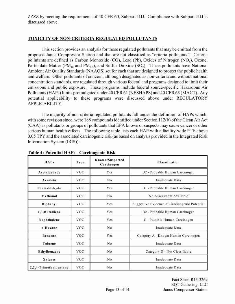
The majority of non-criteria regulated pollutants fall under the definition of HAPs which,with some revision since, were 188 compounds identified under Section 112(b) of the Clean Air Act(CAA) as pollutants or groups of pollutants that EPA knows or suspects may cause cancer or otherserious human health effects. The following table lists each HAP with a facility-wide PTE above0.05 TPY and the associated carcinogenic risk (as based on analysis provided in the Integrated RiskInformation System (IRIS)):
Table 4: Potential HAPs - Carcinogenic Risk
HAPs TypeKnown/Suspected
CarcinogenClassification
Acetaldehyde VOC Yes B2 - Probable Human Carcinogen
Acrolein VOC No Inadequate Data
Formaldehyde VOC Yes B1 - Probable Human Carcinogen
Methanol VOC No No Assessment Available
Biphenyl VOC Yes Suggestive Evidence of Carcinogenic Potential
1,3-Butadiene VOC Yes B2 - Probable Human Carcinogen
Naphthalene VOC Yes C - Possible Human Carcinogen
n-Hexane VOC No Inadequate Data
Benzene VOC Yes Category A - Known Human Carcinogen
Toluene VOC No Inadequate Data
Ethylbenzene VOC No Category D - Not Classifiable
Xylenes VOC No Inadequate Data
2,2,4-Trimethylpentane VOC No Inadequate Data
Fact Sheet R13-3269EQT Gathering, LLC
Page 13 of 14 Janus Compressor Station
All HAPs have other non-carcinogenic chronic and acute effects. These adverse healthaffects may be associated with a wide range of ambient concentrations and exposure times and areinfluenced by source-specific characteristics such as emission rates and local meteorologicalconditions. Health impacts are also dependent on multiple factors that affect variability in humanssuch as genetics, age, health status (e.g., the presence of pre-existing disease) and lifestyle. As statedpreviously, there are no federal or state ambient air quality standards for these specific chemicals. For a complete discussion of the known health effects of each compound refer to the IRIS databaselocated at www.epa.gov/iris.
AIR QUALITY IMPACT ANALYSIS
The estimated maximum emissions of the proposed facility are less than applicabilitythresholds that would define the proposed facility as “major” under 45CSR14 and, therefore, no airquality impacts modeling analysis was required. Additionally, based on the nature and location ofthe proposed source, an air quality impacts modeling analysis was not required under §45-13-7.
MONITORING, COMPLIANCE DEMONSTRATIONS, REPORTING, AND RECORDINGOF OPERATIONS
The draft permit contains extensive and detailed monitoring, compliance demonstration, andrecord-keeping requirements (MRR) on all emission units primarily based on the applicablerequirements contained in the recently issued G35-C General Permit. The requirements are givenunder Section 4.2 (and some additional record-keeping and reporting requirements under Section 4.3and 4.4, respectively) of the draft permit and may be reviewed at that location.
PERFORMANCE TESTING OF OPERATIONS
The draft permit contains performance testing requirements primarily based on the applicablerequirements contained in the recently issued G35-C General Permit. The requirements are givenunder Section 4.3 of the draft permit and may be reviewed at that location.
RECOMMENDATION TO DIRECTOR
The information provided in the permit application indicates that compliance with allapplicable state and federal air quality regulations will be achieved. Therefore, I recommend to theDirector the issuance of a Permit Number R13-3269 to EQT Gathering, LLC for the proposedconstruction and operation of the Janus Compressor Station located near West Union, DoddridgeCounty, WV.
Joe Kessler, PEEngineer
Date
Fact Sheet R13-3269EQT Gathering, LLC
Page 14 of 14 Janus Compressor Station