Embed Size (px)
Citation preview

Learners Resource Package
Engineering Drawing Interpretation 2 NM44/2
ISOMETRIC VIEW OF SHAFT AND PULLEY ASSEMBLY
SHAFT ASSEMBLY SECTIONAL FRONT VIEW
SECOND EDITIONSAMPLE

NM44/2 Engineering Drawing Interpretation 2 Learners Resource Package July 2004
1
First published in October,1998 by TAFE Manufacturing & Educational Services PO Box 218 Bankstown NSW 2200 2nd Edition November 2000 3rd Edition July 2004 This work is copyright. Any inquiries about the use of this material should be directed to the publisher. 8 New South Wales Technical and Further Education Commission 2004 Permission to use certain illustrations from the publication “Pen Pencil & Paper” written and illustrated by Raymond D Bell and Mechanical Drawing Exercises, Engineering Graphics Book 2 compiled by Dan Quigley has been granted by: Department of Education Victoria ENGINEERING DRAWING INTERPRETATION 2 NM44/2
CONTENT Introduction
What you will need for this module 2 Module organiser 3
Module sections
Section 1 Pictorial views 5
Section 2 Orthogonal projection 24
Section 3 Dimensioning 43
Section 4 Surface texture - linear/geometric tolerancing 53
Section 5 Section detail and assembly drawings 74 Section 6 Drawing analysis and data sheets 110
SAMPLE

NM44/2 Engineering Drawing Interpretation 2 Learners Resource Package July 2004
5
Section 1: Pictorial Views PURPOSE
In this section we will extend the work completed in MEC076 Engineering Drawing Interpretation on isometric and oblique projection. You will be required to sketch shapes and then draw them accurately using drawing equipment.
Objectives At the end of this section you should be able to: Construct detailed pictorial views from two and three view third angle orthogonal drawings
of simple engineering objects. Advice on section completion. The work may need to be completed inside and outside the classroom if the majority of exercises are attempted.
SAMPLE

NM44/2 Engineering Drawing Interpretation 2 Learners Resource Package July 2004
6
Projection - Methods of drawing An engineering drawing must ideally show the true shape of an object as well as all necessary sizes to allow it to be made and interpreted correctly. A pictorial drawing ( Axonometric, oblique or perspective) may give an instant impression of an object and its use, but, be ineffective in showing correct proportions and dimensions as an orthogonal drawing would.
Projection Distinctive features Generic Particular
Application
Orthogonal
Third angle
(preferred)
First angle
Generally a multiview
drawing
Axanometric Isometric
Dimetric
Trimetric
Parallel lines
of sight
(Orthogonal)
Oblique Cavalier
Cabinet
General
Converging
Line of sight
Perspective One-point
(parallel)
Two point
(angular)
Three point
(oblique)
Single view
‘Pictorial’ drawings
Pictorial drawings The table above has introduced a number of terms, or names that you might not be familiar with. Orthogonal, Isometric, Oblique and Perspective are probably words that you are already familiar with. Why have all the listed variations? No system, where we try to draw a three dimensional object on a flat sheet of paper, is perfect. Consider the isometric drawing of a block with a 45E chamfer on each corner. These chamfers come out as vertical or horizontal lines. On two corners, the lines are dead in line with the lines showing each extremity of the block. On a simple object like this, our eyes are not confused, and it does not create much of a problem. However, on more complex objects this can not be overlooked, and the object needs to be viewed from a different angle to avoid misinterpreting the shape of the job.
SAMPLE

NM44/2 Engineering Drawing Interpretation 2 Learners Resource Package July 2004
7
Pictorial views Axononmetric drawing There are three basic methods of Axonometric drawing:
Isometric Where the three angles between the three principle axes of the object form equal angles of 120º.
Dimetric Trimetric
Both of these methods use angles and scaled lengths which make them more difficult to draw. The following three drawings show the differences.
Isometric drawing Dimetric drawing Trimetric drawing
FULL SCALE
FULL SCALE
FULL SCALE
FULL SCALE
FULL SCALE
FULL SCALE
120º 120º
120º
X Y
Z
30º 30º 7º
41.5º
Z
X Y
131.5º
131.5º
97º
FULL SCALE
Z
X Y
β α
Note: α and β are variable but not equal.
Scales for X and Y are different and are determined from equations
X
Y
Dimetric and Trimetric drawings are simply variations of Isometric drawings to give clarity. In drawing work the following angles are usually used.
Isometric uses - angles of 30º and 30º. Diametric uses - angles of 7º and 41º 30' Trimetric gives the draftsperson some latitude in that the angles can be arranged to give the best interpretation and indication of shape. The special set square shows angles of 10º, 15º, 25º and 45º that can be used in any combination.
Special set square for dimetric projection Special set square for trimetric projection Dimetric and Trimetric drawings are usually drawn using special set squares and scales True axonometric projection requires scaling of all the principle axes lengths. To simplify drafting procedures it is usual to produce axonometric drawings as explained in the next section of work.
SAMPLE

NM44/2 Engineering Drawing Interpretation 2 Learners Resource Package July 2004
8
Pictorial Drawings
Isometric Oblique Perspective
How accurate are they? Do they give a true picture? When an edge or face is looked at from an angle, the true length is not seen by the eye. Look at the drawing of the 80 mm edge illustrated on this page, and you will see what is meant. However, a great number of pictorial drawings are drawn with edges and faces shown at full length
80
mm
From 60º the 80mm edge looks about 40mm long
From 30º the 80mm edge looks about 68mm long
From straight on you see a true length, that is 80mm.
As the viewing point moves away from a normal (right angles to) position, the length of the edge or face being viewed appears shorter. If pictorial drawings are to be made true to size, these shortened lengths should be used. In most cases this is not done as it would be too time consuming, hence, most pictorial drawings give a distorted view by using full lengths instead of scaled lengths.
The difference between: Isometric drawing Isometric projection
30º15’
The difference between an Isometric drawing (solid line) and an Isometric Projection (Dotted Line). Isometric drawings are easier and quicker to draw and are mostly used. Isometric projections are time consuming and difficult to draw, however they do give the correct size. You can see the difference between an Isometric DRAWING and an Isometric PROJECTION. The isometric drawing makes the 20 mm cube look larger than an actual 20mm cube would look to the eye. To make the cube look right, isometric projection would have to be used. The drawing is the solid line, the projection is the dotted line. To draw the projection, the 20mm cube is tilted forward on one corner until all the lines appear equal in length to the eye. The cube, and any other shape, is calculated to be tilted through 35º15' for this to take place. You can see the extent of the work to be completed in order to produce an isometric projection. A side view drawn at 35º15' has to be constructed first so that the correct heights can be projected across. This is time consuming, hence most of the isometric views made are isometric drawings, not isometric projections. This means that when an isometric drawing is looked at we are seeing an oversize object. The proportion of oversize can be determined from the views. All isometric work to be undertaken in this module will utilise isometric drawing.
SAMPLE
NM44/2 Engineering Drawing Interpretation 2 Learners Resource Package July 2004
9
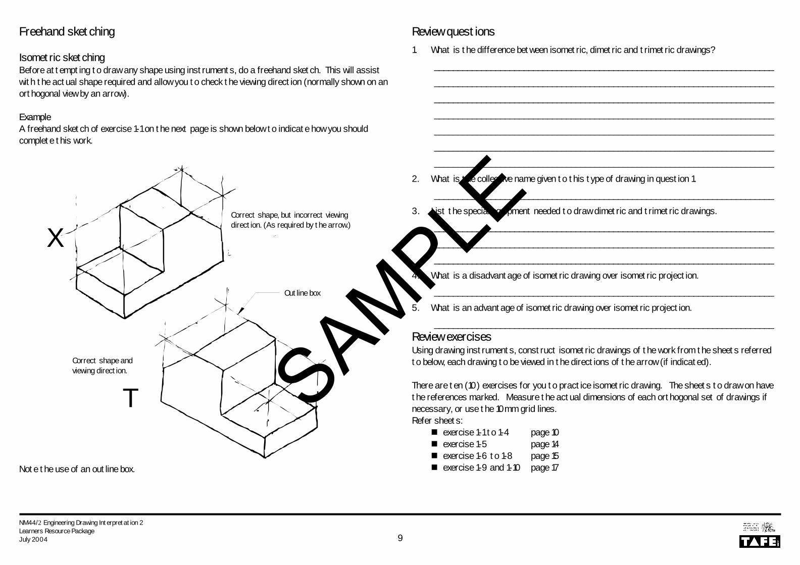
Freehand sketching Isometric sketching Before attempting to draw any shape using instruments, do a freehand sketch. This will assist with the actual shape required and allow you to check the viewing direction (normally shown on an orthogonal view by an arrow). Example A freehand sketch of exercise 1-1 on the next page is shown below to indicate how you should complete this work.
Note the use of an outline box.
Review questions 1. What is the difference between isometric, dimetric and trimetric drawings?
________________________________________________________________________
________________________________________________________________________
________________________________________________________________________
________________________________________________________________________
________________________________________________________________________
________________________________________________________________________
________________________________________________________________________
2. What is the collective name given to this type of drawing in question 1.
________________________________________________________________________
3. List the special equipment needed to draw dimetric and trimetric drawings.
________________________________________________________________________
________________________________________________________________________
________________________________________________________________________
4. What is a disadvantage of isometric drawing over isometric projection.
________________________________________________________________________
5. What is an advantage of isometric drawing over isometric projection.
________________________________________________________________________ Review exercises Using drawing instruments, construct isometric drawings of the work from the sheets referred to below, each drawing to be viewed in the directions of the arrow (if indicated). There are ten (10) exercises for you to practice isometric drawing. The sheets to draw on have the references marked. Measure the actual dimensions of each orthogonal set of drawings if necessary, or use the 10mm grid lines. Refer sheets:
exercise 1-1 to 1-4 page 10 exercise 1-5 page 14 exercise 1-6 to 1-8 page 15 exercise 1-9 and 1-10 page 17
X
T
Correct shape, but incorrect viewing direction. (As required by the arrow.)
Correct shape and viewing direction.
Outline box
SAMPLE

NM44/2 Engineering Drawing Interpretation 2 Learners Resource Package July 2004
10
Exercise:: Draw or sketch the following objects (Exercise 1-4) in isometric projection
Exercise 1 - 1 Exercise 1 - 3
Exercise 1 - 2
STUDENTS NAME DRAWING NoMANUFACTURING & ENGINEERING DIVISION NM44-1-5
SAMPLE