Embed Size (px)
Citation preview
Level 1 Construction Fundamentals Study Guide
43
ENGINEERING CONCEPTS
Constructors must have a basic understanding of the natural characteristics of materials which areincorporated into the construction process. This information can be obtained from publishedtechnical reports and advertising material prepared by suppliers. Some sources of informationconcerning technical properties of specific materials can be found in these sources.
Sweets Catalog compiles technical construction material advertising literature published bysuppliers. It is organized by the Construction Specification Institute’s Master Format which isorganized by 16 Divisions. American Society for Testing and Materials (ASTM) is anorganization engaged in the standardization of technical specifications and testing methods.American Standards Association (ASA) develops national industrial standards representingmanufacturers, technical organizations and government agencies. Underwriters Laboratories(UL) is a nonprofit organization which investigates and tests materials, products, equipment,construction methods and construction systems in its laboratories. A UL-APPROVED seal ofapproval is recognized as a safeguard against hazards to life and property. Many specificationsrequire UL approvals. Thomas’ Register complies manufacturers’ information on variousmanufactured products.
Engineering Material PropertiesThe Materials most widely used in the construction industry are aggregates, asphalt, Portlandcement concrete, masonry, iron, steel and wood. Therefore, a basic understanding of theirmaterial properties is reviewed here. The Specifications are developed to provide the contractorwith an in-depth description of what materials to use, the characteristics the materials must have,the installation procedures the contractor must follow, the manufacturer’s instructions and theinspection and testing procedures that will be utilized to verify the proper installation andstrengths. The properties most often considered when selecting materials are outlined below.
Aggregate PropertiesAggregates are particles of random shape and size. They are found in nature as sand, gravel, orrock that can be crushed into particles. Aggregate sizes vary from several inches to the smallestgrains of sand. Particles smaller than the size of a grain of sand are considered impurities. Aggregates are normally used as bases placed on top of the soil to uniformly distribute the load over the soil for a footing or road. The qualities that indicate the usefulness of aggregate for theconstruction industry are the weight, the strength of the particles to resist repetitive freezing andthawing, the strength of the mass to transmit a compressive force, the strength of the individualparticles to resist being crushed the strength of the aggregate particles to resist wear by abrasion,the adhesion of the aggregate particles to a cementing agent such as Portland cement or asphaltand the permeability of the mass. Weight is important for large stone used for riprap. Riprap isplaced at the end of culverts or along the edge of a body of water to prevent erosion. Theaggregate quality of resisting weathering is called soundness of the aggregate. The aggregate
Level 1 Construction Fundamentals Study Guide
44
particles at the surface of asphalt or concrete are subject to abrasion from the vehicle wheels.Also, in an asphalt pavement the aggregate particles throughout the asphalt pavement are subjectto abrasion because the pavement is continuously shifting under the weight of the vehicles whichcauses the particles to rub against each other. Finally, permeability is a measure of the ease withwhich water will flow through an aggregate’s voids. High permeability is needed if the aggregateis used as a filter or drain.
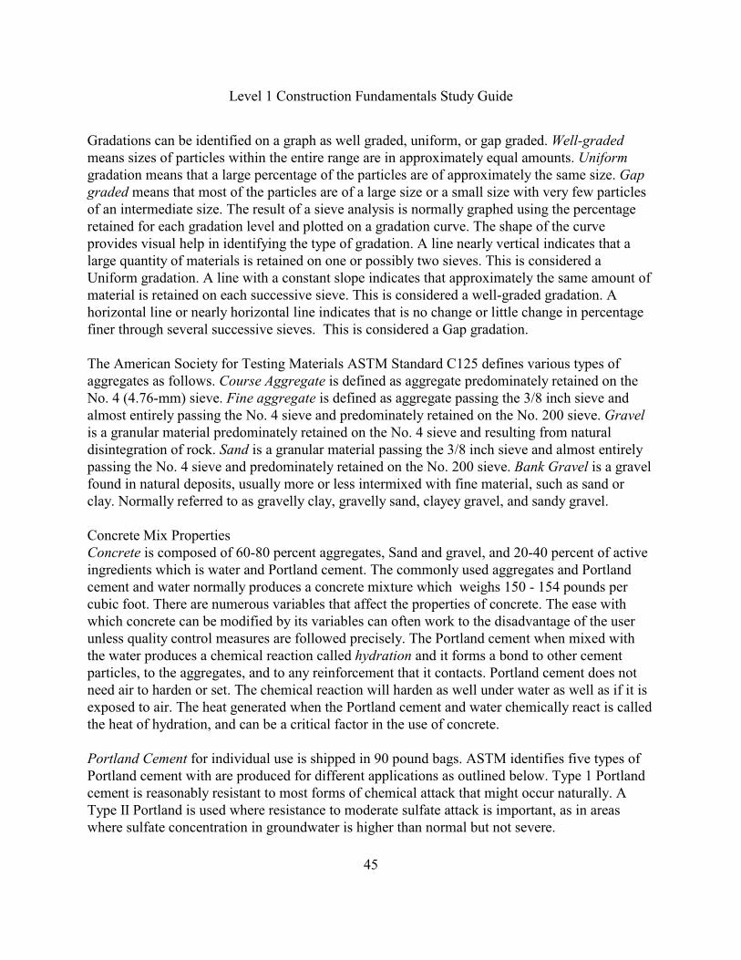
Aggregate Size and Gradation are important for all construction applications. The mostimportant features are range of sizes and gradation. Gradation is the distribution within the rangecovered. A set of sieves stacked on top of each other is used to determine size and gradation. Asample of the aggregate to be analyzed is placed in the top sieve which has the largest holes. TheSieve sizes commonly used for aggregates in the construction industry and the actual dimensions,the sizes designated in millimeters and inches or fractions of an inch are shown below. The sievedesignations indicate the clear openings between wires which are squares with the givendimensions. When a size is given as a number, such as a No. 40 sieve, it means there are thatnumber of holes in a lineal inch. Therefore, the No. 40 sieve has a total of 40 openings per linealinch and 1600 openings in a square inch. The openings are not 1/40 of an inch in width becausethe wires take up much of the space. Therefore, the openings are actually smaller but it is anapproximate method for estimating opening sizes in inches.
Sieve Designation Sieve Aggregate
Descriptionmm inches Opening Size in Inches
4 inches 4.00 Cobbles above 3inches
75 mm 3 inches 3.00
Coarse Gravels
3" - 3/4"37.5 mm 1-1/2 inches 1.50
19.0 mm 3/4 inch 0.75
12.5 ½ inch 0.50
Fine Gravels
3/4 - No. 46.3 mm 1/4 inch 0.25
4.76 mm No. 4 0.187
2.36 mm No. 8 0.0937 Course Sand No. 4-10
1.18 mm No. 16 0.0469 Medium Sands
No 10 - No 400.6 mm No. 30 0.0234
0.3 mm No. 50 0.0117 Fine Sands
No. 40 - No. 200
Below 200 Silt/Clay0.15 mm No. 100 0.0059
0.074 mm No. 200 0.0029
Level 1 Construction Fundamentals Study Guide
45
Gradations can be identified on a graph as well graded, uniform, or gap graded. Well-gradedmeans sizes of particles within the entire range are in approximately equal amounts. Uniformgradation means that a large percentage of the particles are of approximately the same size. Gapgraded means that most of the particles are of a large size or a small size with very few particlesof an intermediate size. The result of a sieve analysis is normally graphed using the percentageretained for each gradation level and plotted on a gradation curve. The shape of the curveprovides visual help in identifying the type of gradation. A line nearly vertical indicates that alarge quantity of materials is retained on one or possibly two sieves. This is considered aUniform gradation. A line with a constant slope indicates that approximately the same amount ofmaterial is retained on each successive sieve. This is considered a well-graded gradation. Ahorizontal line or nearly horizontal line indicates that is no change or little change in percentagefiner through several successive sieves. This is considered a Gap gradation. The American Society for Testing Materials ASTM Standard C125 defines various types ofaggregates as follows. Course Aggregate is defined as aggregate predominately retained on theNo. 4 (4.76-mm) sieve. Fine aggregate is defined as aggregate passing the 3/8 inch sieve andalmost entirely passing the No. 4 sieve and predominately retained on the No. 200 sieve. Gravelis a granular material predominately retained on the No. 4 sieve and resulting from naturaldisintegration of rock. Sand is a granular material passing the 3/8 inch sieve and almost entirelypassing the No. 4 sieve and predominately retained on the No. 200 sieve. Bank Gravel is a gravelfound in natural deposits, usually more or less intermixed with fine material, such as sand orclay. Normally referred to as gravelly clay, gravelly sand, clayey gravel, and sandy gravel.
Concrete Mix PropertiesConcrete is composed of 60-80 percent aggregates, Sand and gravel, and 20-40 percent of activeingredients which is water and Portland cement. The commonly used aggregates and Portlandcement and water normally produces a concrete mixture which weighs 150 - 154 pounds percubic foot. There are numerous variables that affect the properties of concrete. The ease withwhich concrete can be modified by its variables can often work to the disadvantage of the userunless quality control measures are followed precisely. The Portland cement when mixed withthe water produces a chemical reaction called hydration and it forms a bond to other cementparticles, to the aggregates, and to any reinforcement that it contacts. Portland cement does notneed air to harden or set. The chemical reaction will harden as well under water as well as if it isexposed to air. The heat generated when the Portland cement and water chemically react is calledthe heat of hydration, and can be a critical factor in the use of concrete.
Portland Cement for individual use is shipped in 90 pound bags. ASTM identifies five types ofPortland cement with are produced for different applications as outlined below. Type 1 Portlandcement is reasonably resistant to most forms of chemical attack that might occur naturally. AType II Portland is used where resistance to moderate sulfate attack is important, as in areaswhere sulfate concentration in groundwater is higher than normal but not severe.
Level 1 Construction Fundamentals Study Guide
46
A Type III Portland cement is called a High-Early-Strength because it achieves its specifiedstrength in 7 days rather than in 28 days, but there is also a corresponding increase in the heat ofhydration. A Type IV Portland cement referred to as Low Heat is used where the rate and amountof heat generated must be minimized. It is primarily used in large mass placements of concretesuch as deep or thick foundations. A Type V Portland cement has high resistance to sulfate attackis important. It is primarily used where the soil or ground water contains high sulfateconcentrations.
The Water/Cement Ratio determines the strength of Portland cement concrete. This ratio is themost important parameter used to control the compressive strength of concrete. There is aminimum Water/cement ratio required for complete hydration of all the cement molecules. But,an excessive amount of water reduces its strength, hardness, durability and resistance to chemicalattack and resistance to freeze-thaw. Thus the construction worker who adds water to the mix tomake it more workable is significantly reducing all the desirable characteristics of the finishedconcrete. All of the desirable properties of the finished concrete, such as durability, hardness,abrasion resistance, etc. are improved as the strength increases.
Air-Entrainment of Portland cements is the process of adding microscopic bubbles of air whichare distributed uniformly throughout the mix. Air entrainment provides improved resistance tofreeze-thaw and to scaling caused by chemicals and salts used for ice and snow removal.
Concrete ReinforcementConcrete Reinforcement is used in most structural applications because Portland cement concreteis quite weak in tension. Therefore, it is reinforced for tension with deformed reinforcing bar alsoknown as rebar. In the United States, the Concrete Reinforcing Steel Institute (CRSI) Manual ofStandard Practice describes the selection, use and standard placement methods for bar supportsand reinforcing bar. The bar supports are commonly known as chairs and bolsters. Reinforcing ismanufactured for a variety of yield stresses or grades. The most common reinforcement gradesare Grade 40, Grade 50, Grade 60 and Grade 75. For these grades, the yield stress is 40,000,50,000, 60,000, and 75,000 psi, respectively. Reinforcement is rolled into round bars withdeformed surfaces designed to improve the adhesion to the concrete.
There are a few different types of Concrete Reinforcement. The two primary types used in theUnited States are Welded Wire Fabric (WWF) and Deformed reinforcing. Welded Wire Fabric(WWF) containing of wires arranged in a square or rectangular configuration and welded at theirintersection. This designation identifies a Plain wire is denoted by the letter “W” [MW] anddeformed wire by the letter “D” [MD”]. The brackets [ ] indicate Metric Units.

Level 1 Construction Fundamentals Study Guide
47
The Welded Wire fabric designation of: WWF 6 x 12 - W16 x W8 [152 x 305 - MW103 xMW52]. This is identified as follows. The 6 indicates the Spacing (inches) of the longitudinalwires which is 6 inches [152mm] in this example. The 12 indicates the Spacing (inches) of thetraverse wires which is 12 inches [305 mm] in this example. The W16 [MW103] indicates thelongitudinal plain wire size and the W8 [MW52] indicates the traverse wire size.
Deformed Reinforcing Bar is specified as a bar number such as a #3 bar or #4 bar. The diameter isdetermined by taking the bar # and dividing by 8. Therefore, a #3 bar is 3/8 inch in diameter. A #4
bar is 4/8 or ½ inch. The Deformed Rebar table below provides the identifying number onreinforcing and its corresponding Nominal Dimension in inches, the Diameter and the Weightper Foot in Pounds.
Bar No. Bar size in
inches
Diameter
in inches
Area
Sq. in.
Perimeter in
inches
Weight-lbs per
foot
1 1/8
2 1/4 Rd. 0.250 0.05 0.786 0.167
3 3/8 rd. 0.375 0.11 1.178 0.376
4 ½ rd. 0.500 0.20 1.571 0.668
5 5/8 rd. 0.625 0.31 1.963 1.043
6 3/4 rd. 0.750 0.44 2.356 1.502
7 7/8 rd. 1.875 0.60 2.749 2.044
8 1 rd. 1.000 0.79 3.142 2.670
9 1 sq. 1.128 1000 3.544 3.400
10 1 1/8 sq. 1.270 1.27 3.990 4.303
11 1 1/4 sq. 1.410 1.56 4.430 5.313
14 1 ½ sq. 1.693 2,25 5.320 7.650
18 2 sq. 2.257 4.00 7.909 13.600
Types of Bar SupportsBar supports are used to position reinforcing bars in reinforced concrete to ensure a minimumamount of concrete cover over the rebar. The bar supports may be made of steel wire, plastic orprecast concrete. Bar supports are not normally shown on the plans and they are not furnished bythe reinforcing steel supplier which generally means that the contractor must follow the standardwhich is incorporated by reference and the reference standard is found in the TechnicalSpecifications. Normally, the Bar Supports are not found on the Contractor’s plans.
Level 1 Construction Fundamentals Study Guide
48
Reinforcement PlacementConcrete Reinforcement is Placed according to a moment diagram for a beam that is supportedby two columns under typical load conditions. The beam will be under tension on the bottom ofthe section at mid span between the two columns and it will be under tension on the top of thesection over the columns. Therefore, you must place the proper size of reinforcing bar, located inthe correct position in both regions to sustain these tensile forces.
As a general rule, the minimum standard Concrete Cover over Reinforcement is specified fromthe outside of the bar to the face of the concrete and they are based on the size of the bar and thelocation as follows. Three inches at sides where concrete is cast against earth and on bottoms offootings. Two inches for bars larger than a #5 where concrete surfaces would be exposed to theweather and 1-1/2 inches for smaller than #5 bars. 1-1/2 inches over spirals and ties in columns.1-1/2 inches to nearest bars on the top, bottom and sides of beams and girders. Also, a 3/4 of aninch cover is needed for #11 rebar and smaller bars on top, bottom and sides of joists and on topand bottom of slabs where concrete surfaces are not exposed to the ground or weather. 1-1/2inches for #14 and #18 bars. Also, 3/4 of an inch cover is required from the faces of all walls notexposed directly to the ground for #11 and smaller bars.
Masonry PropertiesOrganizations such as the International Masonry Institute (IMA), and the Brick Institute ofAmerica (BIA) have established an engineered approach to Masonry Design and Construction.Their efforts continue to provide the latest in engineering data, design guidelines, andconstruction practices for masonry construction. Masonry wall units are held together withmortar and the quality of the mortar mix effects the wall. Mortar binds the masonry unitstogether into a single permanent structure and it seals the joints against moisture and airpenetration. The mortar acts as the bond for the various components of the masonry structuresuch as reinforcement rebar, metal ties and anchor bolts. Portland cement, lime, sand and waterare combined to produce mortars which have good durability and high compressive strengths.But, masonry cement, sand, and water are combined for convenience. The masonry cement ispre-blended by the manufacturer and it will normally include lime, an air-entraining agent, andother ingredients which produce the desired properties. The properties of the individualingredients are provided below.
Portland cement used in mortars allows Types I, II, and III. Air-entraining Portland cementshould be used with extreme caution since the research has shown that there are wide variationsin the actual measured air content at the job site. The compressive strength of the mortar dependsupon the proportion of Portland cement in the mix.
Hydrated Lime is essential to good quality mortar. It is a key ingredient and it is important tounderstand its characteristics and effects on mortar. The lime component improves workability,elasticity and water retention. Water retention in a mortar prevents rapid loss of water from
Level 1 Construction Fundamentals Study Guide
49
mortar in contact with the masonry units. Lime also improves its bond strength and improves themortar’s plasticity and flexibility. Lime undergoes the least amount of change in volume whichmeans it shrinks the least after hardening. Mortar is resistant to weather and should be able toresist strong winds, freezing temperatures, and alternate wet and dry weather. These cycles arebeneficial to lime-based mortar, and they increase the overall strength of the mortar as it ages.
Sand acts as a filler in mortar which contributes to the strength of the mix. Natural sand is usedin most mortars. Sand decreases the shrinkage of mortar which occurs in setting and drying,therefore, minimizing cracking. It is important to use a good grade of sand. Water used in mortarshould be clean and free from alkalis, salts, acids, and organic matter. Retempering is theaddition of water to mortar mixes that have lost water while sitting on the mortar board. Thepractice of retempering will reduce the compressive strength, but it increases the bond strength ofthe mortar mix. Many times, the CSI Division 04 Masonry, the technical specifications limit thenumber of times that retempering is permitted and establishes a time limit for the use of a mortar.
Types of Masonry CementAs mentioned before, Masonry Cement is a pre-blended by the manufacturer and used forconvenience at the job site. The American Society for Testing Materials (ASTM) recognizes fivetypes of mortars for masonry. They are types M, S, N, O, and K. Type M is the strongest. TypesO and K are the weakest. Until recently, the masonry codes recognized all five mortar types, but,the latest masonry codes focus primarily on the use of Type S and Type N.
Type N mortar is a medium-strength mortar recommended for use in exposed masonry abovegrade. Typically it is used for exposed exterior building walls, interior load-bearing walls andinterior non load-bearing walls or partitions, chimneys, and parapet walls. Type S mortar is amedium-high strength mortar which is used where high bond strength and lateral strength areimportant. Type S mortar is recommended for use in foundations, basements, exterior walls,interior load-bearing walls, reinforced walls and non-reinforced masonry where maximumflexural strength is required.
Types of Masonry Walls and Their ComponentsMasonry Walls are formed from various types of masonry units and their backing can be block,brick, wood or concrete. The descriptions below describe the most common types of masonrywalls. The concrete block wall consists of masonry units bonded together with mortar to formload bearing or non-load bearing walls above or below grade. The concrete masonry block unitscome in various sizes and wall thicknesses. The solid brick wall consists of two tiers or wythes ofbrick which is bonded together with header bricks. The composite wall consists of face brickwith a header brick interlocked back into a block backup wall containing header blocks to receivethe header brick and regular block. The insulated cavity wall consists of two tiers or wythes ofmasonry separated by a continuous air space and bonded together using metal ties to providewater drainage using flashing and weep holes. The Brick Institute of America recommends the
Level 1 Construction Fundamentals Study Guide
50
construction of cavity walls where there is severe weather exposure, or where a maximumresistance to rain penetration is desired. Finally, a veneer masonry wall is a single thickness ofmasonry units attached to the backing with corrugated metal ties but it is not bonded to thebacking. A veneer wall is a non-load bearing wall used primarily for decorative purposes.
There are various types of metal ties used to bind the face wall to the backup wall. For instance,the dovetail anchor is used to tie masonry units to a concrete wall. The anchor fits into a slotembedded in the concrete wall. The galvanized metal tie is used to bind the veneer brick wall tothe backing. The rectangular tie is used to tie the face wall to the backup wall in a composite wallor a cavity wall. The reinforced masonry wall consists of masonry units tied together usinghorizontal reinforcing wire or metal ties and vertical reinforcing bars. The vertical reinforcingbars in the masonry cores are grouted in either a low-lift or high-lift grouting process dependingupon what it calls for in the technical specifications.
A Masonry Wall contains the following components. Horizontal joint reinforcement is used totie masonry units together to form a single structural unit. There are some types of metal jointreinforcement which are embedded in the horizontal mortar joint. The ladder or truss typereinforcement is used to tie masonry units together. Control joints are vertical joints that separatewalls into sections and allow freedom of movement. They occur at specified intervals in long,straight walls or where abrupt changes in wall thicknesses occur. They also should be placed atopenings; at intersections of main walls and cross walls; and at locations of structural columns inmain walls.
A bond beam is a continuous, cast-in-place lintel block with reinforcement bars placed in thecore of the lintel block. Bond beams may run around the perimeter of a building or betweencontrol joints. They may also be utilized as a lintel over an opening. Bond Beams are used as acontinuous tie for exterior block walls where control joints are not required. They also act asstructural members transmitting lateral loads to other structural members, and they can providebearing for beams and joists. Lintels are used over openings in block walls to carry the loadaround the opening. They can consist of precast concrete units, structural steel shapes, a bondbeam with reinforcement or a combination of materials. Bond beams and lintel are installed inconjunction with the masonry wall is being placed.
Masonry Brick Positions and PatternsBrick is laid in various positions in the construction of solid brick walls, reinforced brick walls,or cavity walls. There are six Brick Positions. The stretcher position is a brick laid in a horizontalposition with the longest, narrowest side facing the front of the wall. The stretcher position is themost common brick position. The header position is a brick laid in a horizontal position with theshortest, narrowest side facing the front of the wall. This is also referred to the header coursewhere a masonry unit is laid over two individual wythes of walls, thereby tying them together.The soldier position is a brick laid in a vertical position with its longest, narrowest side facing

Level 1 Construction Fundamentals Study Guide
51
the front of the wall. The shiner position is a brick laid in a horizontal position with the largestside facing the front face of the wall. The rowlock position is a brick laid in a horizontal positionwith the narrowest side or face edge placed in the bed of mortar and the longest side runningback into the wall. The rowlock position is commonly used on window sills. The Sailor positionis a brick that is laid in a vertical position with the largest side facing the front of the masonrywall.
Many times the brick positions are arranged in a wall to form a Brick Pattern or recurring designwhich is referred to as a Brick Pattern Bond. There are five basic structural bond patterns forbrick and they are described below. The Running bond pattern consists of all bricks laid in astretcher position with a one-half or one-third lap. This is commonly referred to as the stretcherbond pattern. The Common or American bond pattern consists of all stretchers with a course ofheader brick at a specified interval such as fifth course, sixth course or seventh course header.Another version is the header course contains a Flemish header. The Flemish bond patternconsists of alternating stretcher and header bricks on the same course. The headers on every othercourse should be centered over the stretcher below. The English bond pattern consists ofalternating courses of header and stretcher bricks. The Stack bond pattern consists of masonryunits laid directly over one another so that all of the head joints line up in a plumb verticalposition. The stack bond is used for decorative purposes and structurally it is the poorest of all ofthe bonds discussed since there is not overlapping of the masonry units.
Structural Steel The most common Structural Steel Shapes are the Wide Flange (W), the Standard I section (S),the Channels (C), the Hollow Structural Sections (HSS), Structural Tees (T, ST or TS), Angleiron with equal and unequal legs (p), the I-shaped steel pile section (HP), and plate steel. WideFlange (W), the Standard I section (S), the Channels (C) all follow the same designation format.The letter indicates the steel shape, the first number indicates the nominal depth of the steelmember and the second number indicates the nominal weight per foot. For example, the steelshape designation of W 14 x 90 means the capital letter W tells you that the shape is a WideFlange (W), the 14 indicates that the nominal depth is 14 inches, and the 90 indicates that thenominal weight per foot is 90 pounds per lineal foot.
Channels use the same designation sequence as the W and S except the structural steel shape anddesign properties are different. Channels are usually used as secondary framing members whenloads and spans are too great. They are used as wall girts which are horizontal members attachedto the columns to support siding. Channel is also used as roof purlins which are the framingmembers spanning between the roof beams to support the roof deck. Channel can also be usedfor door and window frames, stairs, stringers, and as web and cord members in trusses. Anglesare used as the connecting pieces for beams, as chord and web members in light trusses andjoists. They are also used as bracing, and as reinforcing around openings normally called lintelsand as supports for mechanical equipment. The American Institute of Steel Construction (AISC)
Level 1 Construction Fundamentals Study Guide
52
publishes a manual titled, Specification for the Design, Fabrication and Erection of StructuralSteel for Buildings. This manual covers structural steel design properties with nominaldimensions and weight, and steels construction methods.
Prior to the fabrication of each structural steel member the manufacturer must submit to thecontractor a shop drawing indicating the size of the member, the detailed dimensions for theconnectors and dimensions for each member in the structure. During the structural steelfabrication process at the manufacturers location, each piece of steel is given an erection markthat allows the contractor to identify each member at the job site. The erection markings for eachmember are then organized into a set of erection drawings which are issued to the contractorindicating the locations and proper positioning of each piece of steel within the structure.
Open-web Steel JoistsThese are lightweight trusses that are used for supporting roofs and floors. The most commonjoist series are the K-Series, the LH Series, the DLH Series and the Joist Girders. The K series isnormally fabricated in depths that range from 8 inches thru 30 inches and spans up to 60 feet.The LH is fabricated in depths that range from 18 inches thru 48 inches and spans up to 96 feet.The DLH is fabricated in depths that range from 52 inches thru 72 inches and spans up to 144feet. The Steel Joist Institute (SJI) publishes numerous manuals such as the StandardSpecifications, Load Tables, and Weight Tables for Steel Joists and Joist Girders.
Steel Floor and Roof DeckThese are roll formed metal in varying configurations for composite metal decks, non-compositemetal decks and metal roofs. Composite floor deck is designated Type “VL”, “VLI”, and “VLR”.The non-composite floor deck is designated Type “C” and the Roof deck is designated Type “B”,“F”, “A”, “N”, and “E”. The Steel Deck Institute publishes numerous manuals such as the SDIManual of Construction with Steel Deck.
Structural steel and metal decking are extremely susceptible to fire, therefore, they must befireproofed based upon the major occupancy classification which is assigned to each buildingduring the initial design stages of the project. Some typical occupancy classifications includearena and theater type occupancies, health care and detention type occupancies, business typeoccupancies, industrial occupancies and residential occupancies.
Fireproofing Structural SteelThe amount of fireproofing that is applied to a structural steel member depends on the fire-resistance rating required and the type of material that is to be protected. Materials normally usedfor the protection of a structural steel frame include regular and lightweight concrete, cellularconcrete, gypsum wall board, plaster, and sprayed-on mineral wool. There are three commonmethods for fireproofing structural steel. You can encase the steel member in concrete. Second,you can encase the steel member with gypsum wallboard. Finally, you can protect the structural

Level 1 Construction Fundamentals Study Guide
53
steel beams, columns and decking with sprayed-on insulation.
Welding SymbolsThe two most common methods for connecting structural steel members in structural steel frameconstruction are bolting and welding. Welding can be done in the manufacturers shop undercontrolled conditions and it can be done at the construction site. Welding is the fusing of twopieces of metal together. The two most often used types of welded connections are the fillet weldand the butt or groove weld. A fillet weld is used to weld two pieces of metal together that areperpendicular to each other. A butt weld is used to weld two pieces of metal together that are setend to end or parallel to each other. The typical butt welded, joints are the Square butt weld, thesingle-V butt weld, and the Single Bevel butt joint. The American Welding Society hasestablished the basic welding symbols for fillet and butt welds, some supplementary weldsymbols and a standard location for elements of a welding symbol. Below is an example of thewelding arrow symbol and their meanings.
Welding Arrow Symbol
BASIC WELDING SYMBOLS SUPPLEMENTARY WELD SYMBOLS
FILLET
BUTT OR GROOVE TYPE WELD
ALL
AROUND
FIELD
WELD
CONTOUR
SQUARE V BEVEL FLUSH CONVEX
** (' * ± =T & ³
Adapted from the American Welding Society manual titled Structural Welding Code D1.1.
Level 1 Construction Fundamentals Study Guide
54
Structural LumberEach piece of lumber is assigned on the basis of its expected use to the category of factory andshop lumber or yard lumber. Yard lumber is used structurally and includes most of the lumber forconstruction. Yard lumber is further divided according to size and shape into boards, dimensionlumber and timbers. Most of the lumber in construction falls into the category of dimensionallumber also called Structural Lumber. Boards are defined as 1" to 1-1/2" thick and 2“ to 12"wide. Boards are further classified as a common grade or rough sawn or surfaced grade ordressed. Dimension lumber is 2" to 4" thick and 2" and wider. Timbers are 5" and thicker and 5"and wider. Boards and dimensional lumber are known by their nominal size such as a 2 x 4which is not 2" thick by 4" wide. Its actual dimensions are 1-1/2" thick x 3-1/2" wide.
Dimension lumber is further divided into Joists and Planks, Light Framing and Decking. Joistsare members that are 2 inches to 4 inches in nominal thickness and at least 6 inches wide. Theyare graded according to their bending strength on their narrow edge. Planks have the samedimensions as joists but they are graded on their wider dimension. Light Framing are membersthat are 2 inches to 4 inches nominal thickness and 2 inches to 4 inches wide. They aresometimes referred to as wood frame construction which consists of studs, plates, joists, andrafters. Decking is 2 inches to 4 inches thick and 4 inches or wider, but they are used on theirwider dimension.
Timbers are further divided into Beams and Stringers and Posts and Timbers. Beams andStringers are members with a width more than 2 inches greater than the thickness. Normally,something called a Beam or Stringer is at least 4 inches thick and at least 2 inches wider thanthey are thick. They are installed horizontally and they are ranked according to the Extreme Fiber
bBending stress (F ) when loaded on the narrower of the two dimensions. Posts and Timbers havea width that is no more than 2 inches greater than the thickness. These are members that areeither square or nearly square in cross section. Normally, they are installed vertically and they are
cranked according to their Compression Parallel to the Grain (F //) because the loads are carriedon the cross section.
Structural lumber, also referred to as dimensional lumber, is a classification of lumber for piecesat least 2 inches thick and it is graded according to its ultimate use and its strength in resisting thestresses placed on each piece in that use. The top grade of most species is select structural grade,which is used only where high strength, stiffness, and good appearance are all required. The nextlower grade is No. 1 grade lumber which may have tiny knots but otherwise it has almost thesame qualities as select structural. The No. 2 grade lumber may have larger knots than No. 1, butthey the knots are tight, and the grade is excellent for floor and roof framing members. The No. 3grade has still more and larger defects and it can be used for sills and some plate members inresidential construction. The Construction grade falls somewhere between Select Structural andNo. 1 grade and it is used for extreme fiber stress in bending. Construction grade is the standardwhere straightness and strength are more important, such as in concrete formwork. The Stud
Level 1 Construction Fundamentals Study Guide
55
cgrade is stiff, straight lumber with a high Compression Parallel to the Grain (F //) value. Thestud grade is excellent for vertical walls in residential construction. The Standard grade and the Utility grade are still lower grades than stud grade lumber. The bottom grade is Economy gradewhich is used for nonstructural purposes. The surfaces of a piece of lumber can be rough sawn ordressed. A dressed piece of lumber with the designation of S1S means smooth on one side. Thedesignation of S2S means smooth two sides and S4S means smooth on all four sides. Dressedcan also be designated S1E which means smooth on one edge or S1S1E which means smoothone side and one edge.
The ASTM D2555 standard titled Methods for Establishing Clear Wood Strength Values,established the stresses at failure and an accurate modulus of elasticity for each wood species.The samples tested under ASTM D2555 have no defects to reduce their strength or stiffness. Allowable stresses for lumber are determined by reducing the stresses in the samples tested underASTM D2555 to provide for a safety factor of approximately 2.5. These allowable stresses andthe modulus of elasticity are published in ASTM D245, Methods for Establishing StructuralGrades for Visually Graded Lumber. The National Forest Products Association (NFPA)publishes a manual titled National Design Specifications for Stress-Grade Lumber and ItsFasteners. This manual includes grades established for each species of wood with allowablestresses for each grade. These stresses are derived by multiplying the basic allowable clear woodstresses by ratios.
Grading standards for softwoods are published by the U.S. Department of Commerce in ProductStandard PS 20 titled the American Softwood Lumber Standard. The grading rules for eachregion are established by numerous organizations whose rules conform to the PS 20 gradingstandard with additions for the special conditions in each region. Then each regionalmanufacturer’s association adjusts or refines their grading rules to categorize its lumber productsaccording to their conditions. Some of the regional associations are the Western Wood ProductsAssociation (WWPA), the Southern Forest Products Association (SFPA), the NortheasternLumber Manufacturers’ Association and the National Hardwood Lumber Association.
Each manufacturers’ association then places their Grading mark or stamp on each piece oflumber. A typical grading mark shows in the upper left portion of the stamp the sawmill numberthat processes the lumber and just below it is the logotype of the manufacturers’ organizationestablishing the grading rules. In the lower right portion of the stamp is the species abbreviationsuch as ES-AF which means Englemann spruce and Alpine fir, or Hem Fir for Hemlock and Fir,or the symbol of a backwards P and a forward P together which means Ponderosa Pine or LP forLodgepole pine. The upper right portion of the stamp states the grade or stress rating such as SELfor Select or CONST for Construction or 2 & BTR STUD which means a No 2. or better gradingfor Studs. The upper right portion of the stamp may contain the stress rating instead of the gradesuch as 1650 f or 1500 f 1.4 E. The remaining information which appears in the middle portionof the stamp may contain its moisture content such as MC 15 which means surfaced at Moisture
Level 1 Construction Fundamentals Study Guide
56
content of 15% or less. Another abbreviation is S-DRY which means surfaced at M.C. of 19% orless. Dry lumber has been seasoned to a moisture content of 19 percent or less. Green lumber hasa moisture content in excess of 19 percent.
Allowable Stresses and StrengthsThe allowable stresses and strengths of wood are divided into the following types. The Extreme
bFiber Bending stress (F ), as single member uses or repetitive member uses, is the stress that
bmust be resisted in a beam undergoing bending. The F value of a beam is the strength of extremefibers in bending when a member is used horizontally such as a floor joist. This generally meansthat the top fibers of a joist will be in compression and the bottom fibers will be in tension. The
bF rating value is the pounds per square inch (psi) that the beam will resist a force exerteddownward at the center of the joist.
cThe Compression Perpendicular to the Grain (F z ) is the stress induced by pressing the fiberstogether in a traverse direction. There is no appreciable difference in strength to resist thiscompression perpendicular to the annual rings or parallel to the rings. The Compression Parallel
cto the Grain (F //) is the stress induced by pressing the fibers together longitudinally. The
vHorizontal Shear Parallel to the Grain (F //) is the stress induced by the tendency for the upper
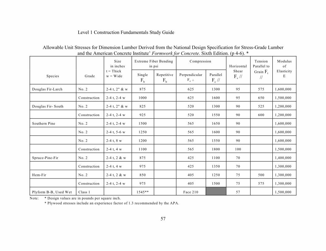
tfibers to slide over the lower fibers as a beam bends. The Tension parallel to the grain (F //) isthe stress induced by pulling apart in a longitudinal direction. The resistance to tensionperpendicular to the grain is extremely weak that it is usually considered negligible. The Modulusof Elasticity (E) is a measure of the stiffness or resistance to deflection. The Modulus ofElasticity is a measure of the ability to resist failure due to excessive deformation. It is used topredict movement under a load and avoid failure due to excessive movement. The modulus ofElasticity (E) value of a piece of lumber is the ratio between the load of the member and theamount the member will deflect under the load. The higher the E value, the stiffer the lumber.Among common woods used for structural lumber Douglas fir and Southern yellow pine havethe highest F and E values. The table below provides the allowable stresses for some typicalspecies of structural lumber. These stresses were derived from recommendations of the NationalForest Products Association (NFPA) and the American Concrete Institute (ACI).
Plywood and PlyformPlywood contains thin layers or plies of wood called veneers. The veneers are bonded togetherwith glues under heat and pressure. Plywood always has an odd number of plies such as three,five or seven. The grain of the plies is alternated and glued at right angles to each other formaximum strength. Plyform uses seven plies and water resistant glues for formwork.
Level 1 Construction Fundamentals Study Guide
57
Allowable Unit Stresses for Dimension Lumber Derived from the National Design Specification for Stress-Grade Lumberand the American Concrete Institute’ Formwork for Concrete. Sixth Edition. (p 4-6). *
Species Grade
Size
in inches
t = Thick
w = Wide
Extreme Fiber Bending
in psi
Compression
Horizontal
Shear
vF //
Tension
Parallel to
tGrain F//
Modulus
of
Elasticity
ESingle
bFRepetitive
bFPerpendicular
cF zParallel
cF //
Douglas Fir-Larch No. 2 2-4 t, 2" & w 875 625 1300 95 575 1,600,000
Construction 2-4 t, 2-4 w 1000 625 1600 95 650 1,500,000
Douglas Fir- South No. 2 2-4 t, 2" & w 825 520 1300 90 525 1,200,000
Construction 2-4 t, 2-4 w 925 520 1550 90 600 1,200,000
Southern Pine No. 2 2-4 t, 2-4 w 1500 565 1650 90 1,600,000
No. 2 2-4 t, 5-6 w 1250 565 1600 90 1,600,000
No. 2 2-4 t, 8 w 1200 565 1550 90 1,600,000
Construction 2-4 t, 4 w 1100 565 1800 100 1,500,000
Spruce-Pine-Fir No. 2 2-4 t, 2 & w 875 425 1100 70 1,400,000
Construction 2-4 t, 4 w 975 425 1350 70 1,300,000
Hem-Fir No. 2 2-4 t, 2 & w 850 405 1250 75 500 1,300,000
Construction 2-4 t, 2-4 w 975 405 1500 75 575 1,300,000
Plyform B-B, Used Wet Class 1 1545** Face 210 57 1,500,000
Note: * Design values are in pounds per square inch.
* Plywood stresses include an experience factor of 1.3 recommended by the APA.
Level 1 Construction Fundamentals Study Guide
58
Plywood contains a center ply which is called the core, and the exposed plies are called the faces.Any other plies between the core and the faces are called the cross bands. The standard width of asheet of plywood is four feet and the most common length is 8 feet. The Plywood sheetthicknesses commonly available are 3/8", ½”, 5/8" and 3/4" for residential structural purposes.Plyform uses 5/8", 3/4", 1", 1-1/8" and 1-1/4". The 3/4" plyform is common.
Each piece of Plywood contains a grading mark or stamp. The American Plywood Association(APA) organizes their plywood into Appearance grades and Engineered grades of plywood.These grade tables are further subdivided into Interior and Exterior Types of plywood. Theinterior types of plywood are made with glue that is adequate for indoor use. The exterior typesof plywood are made with hot resin glue that is unaffected by water and resists weathering. Thesetypes are further subdivided by Grade Designation such as interior, structural I, sturd-i-floor,underlayment, plugged and B-B Plyform.
The engineered grade’s stamp indicates the grade of the veneers, the species group number, theidentification index numbers or the species group, the type of plywood use, the thickness, themill number or product standard and the type of glue is specified. Across the top of most gradestamps are two letters separated by a hyphen. The first letter is the grade of the veneer on thepanel face and the second letter is the grade of the veneer on the panel back. The only letters usedto grade the face veneers qualities are A, B, C, D, and N. A grade A face veneer is smooth, hasno open defects, but may have some neat repairs. A grade B veneer has a solid surface with nosplits wider than 1/32" and all of the defects are repaired with smooth plugs. The grade C veneermay have splits up to ½" and knot holes up to 1-1/2" as long as they do not affect the requiredstrength of the plywood. The grade D veneer is the poorest grade and it has a rough appearanceand knots. The identification index has two numbers. The first identification index number statesthe maximum span if the plywood sheet is used on the roof. The second identification number, tothe right of the slash provides the maximum span if the plywood is used for a sub flooring.
The B-B Plyform Class I or Class II is a concrete grade with a high reuse factor. This has asmooth surface on both sides with no splits and all of the defects are plugged. The Plyform isseven plies, it is water resistant, and it is milled oiled to resist concrete adhering to the surface.Plyform is made only from certain wood species which conform to the APA specifications.Plyform is also available in High Density Overlay (HDO) and Structural 1 grades. Class 1 is themost commonly available plyform.
Statics and Strength of MaterialsAll construction materials must resist a force. A force is a push or pull on a material and the mostcommon force in construction is the pull of gravity. However, other forces that must be takeninto consideration are wind and water. A force exerted on the surface of an object is assumed tobe uniform over the internal areas of the object. Stress is a force per unit area over which theforce acts and it is calculated by dividing the force by the areas on which it acts and it is
Level 1 Construction Fundamentals Study Guide
59
expressed as pounds per square inch (psi) of kips per square inch (Ksi) where a kip is equal to1000 pounds. The strength of a material is the ability to resist a force. Also, the strength of amaterial in technical terms is equal to the stress that the material can resist. Therefore, thestrength of a material has the same units as stress which are expressed in psi or Ksi. This alsomeans that the useful strength of a material is equal to the stress at the point of failure. Failuretakes place when a material can no longer resist the weight applied upon it and the material eitherbreaks or it deforms. Deformation is defined as a change in the outside dimension of a materialcaused by a force. This deformation is expressed in terms of strain which is the total change inthe dimension divided by the original dimension. The term strain means the total change indimension divided by the original dimension. Strain is a ratio, therefore, it has no units, but theamount of deformation and the original length must utilize the same unit to provide a correctratio. They are usually measured in inches. The deformation that can be allowed a materialdepends upon its intended use. A material that deforms slowly when a force is applied to it for anextended period of years, even though the force is too small to cause failure in a short period oftime. This deformation is called creep.
The engineering profession has determined the stress that causes failure for various materials.However, nothing is designed to be stressed to the point of failure. Instead, a lower stress calledthe allowable stress is selected. The failure stress is greater than the allowable stress by a factorwhich is called the safety factor. The safety factor and the allowable stresses for various materialsare published by various organizations. Some organizations that publish allowable stresses arethe American Concrete Institute (ACI) American Institute of Steel Construction (AISC), theConcrete Reinforcing Steel Institute (CRSI), the Steel Joist Institute (SJI) and the National ForestProducts Association. Economy requires that the actual stress be near the allowable. If it is not,then the material is being used inefficiently because using less material would be adequate. Theactual stress is called the working stress. There are three types of stresses and correspondingstrengths. They are compressive, tensile and shearing. Each depends upon the position of theforces with respect to the object.
In Joseph Wujek’s (1999) book titled Applied Statics, Strength of Materials, and BuildingStructure Design he describes the following terms. A beam is a structural member that rests oncertain reactions and it is subject to forces acting normally perpendicular to its longitudinal axis,thereby causing it to bend. In structural design, a beam is a horizontally positioned load-bearingstructural member used in buildings. However, in construction, joists, girders, headers, lintels orpurlins behave like and are treated as beams. A load is an external force applied to beams andother structural forces. The reacting forces at the beam supports which counter the applied loadand keep the beam in static equilibrium are called reactions. The loads and reactions combine tocause the beam to bend.
Level 1 Construction Fundamentals Study Guide
60
There are numerous types of beams. The simple beam spans between two reactions located at theextreme ends of the beam. The overhanging beam is a beam that rests on two reactions andextends beyond one bearing point. The double overhanging beam rests on two reactions and bothbeams ends extend beyond the reactions. The continuous beam is supported by three or morereactions. A cantilever beam extends from a single reaction (p 72).
Moment The moment of a force is a measure of its ability to cause turning, rotating or twisting about anaxis of rotation. The moment (M) can be determined as the product of a force, P, and theperpendicular distance, d, from the line of action of the force to the axis of rotation about whichwe can find the moment.
The moment (M) = Pd. A moment is always expressed in unit of force (P) times distance (d) andthe common units for moments (M) are pound-inches (lb-in.), pound-feet (lb-ft.), newton-meters(N-m), and kip-feet (k-ft.). A kip is 1000 pounds.
The equations of static equilibrium indicate that the sums of the horizontal forces must be zero.
xThis is expressed as 3 F = 0. Second, the sum of the vertical forces with an upward forceassigned a positive (+) sign and a downward force given a negative (-) sign and setting them
vequal to zero. This is expressed as 3 F = 0. Third, the sum of the moments about any axismust be zero. This is expressed as 3 M = 0 (p 74).
For example, a wooden beam 12 feet long and it carries a concentrated load of 150 pounds at a
2 1distance of 4 feet from Reaction (R ). Reaction (R ) is pinned 8 feet from the load. What are the
1 2values for R and R ?
Using the three equations of static equilibrium from above and the wooden beam exampledescribed above, the sum of the horizontal forces is zero since there are no horizontal forces
xprovided. Therefore, 3 F = 0. Second, the sum of the vertical forces must be equal to zero. In
v 1 2 1 2the example, 3 F = 0 which is: 150 lbs - R - R = 0. We also know that R + R = 150 lbs.
1 2We know that Reaction R is pinned which is the axis of rotation and R is 12 feet from the axis
1of rotation and is acting with a tendency to cause counterclockwise rotation about R . Therefore,
23 M = 0 = + (R x 12 feet) - (150 pounds x 8 feet)
20 = 12 R - 1200 lb-ft
212 R = 1200 lb-ft
212 ft R = 1200 lb-ft12 ft 12 ft
2R = 100 lb
Level 1 Construction Fundamentals Study Guide
61
v 1 2 2Finally, 3 F = 0 = R + R - 150 lb. Also, R = 100 lbs.
1Therefore, R + 100 lbs - 150 lbs.
10 = R - 50 lbs
1R = 50 lbs
ShearA beam is designed to resist the bending and shearing stresses that are induced by the effects ofthe applied loads and the resulting reactions. The designer utilizes the loads and the resultantforces to determine the shear forces and the bending moments across the beam length. The shearforces and bending moments determine the beam material properties and cross section requiredto withstand these stresses. Shear stress occurs when two forces with parallel but offset lines ofaction act in opposite directions on the beam.
A beam under a load has the tendencies for it to fail due to either vertical shear or horizontalshear. Vertical shear is the shearing force that tends to cause a member to fail by cuttingperpendicular to the beam’s longitudinal axis. This occurs at or near the beam supports. This typeof failure is often a concern in short beams carrying heavy loads. Horizontal Shear is thetendency of theoretical layers in a member to slide horizontally.
Joseph Wujek (1999) says that Vertical shear (V) is calculated at any point along a beam by
up downsumming any forces acting upward (F ) and subtracting any forces acting downward (F ) tothe left of the section under consideration. This method assumes that the beam is in staticequilibrium. The definition for calculating a vertical shear force (V) is the vertical shear force atthe section under consideration is equal to the sum of the forces acting upward minus the sum of
upthe forces acting downward calculated to the left of the section. The formula is V @ x = 3 F -
down3 F to the left of the section under consideration (p 189).
The section under consideration and the shear force calculations are cited as a measurement fromthe left end of the beam. For example, V @ 2 feet indicates that the computation is made with thesection placed 2 feet away from the left end of the beam. Also, the location of the section of theshear force calculation is followed by a negative (-) or positive (+) symbol which denotesplacement of the section just to the left (-) or just to the right (+) of the concentrated force.
Also, there is no vertical shear force that exists directly below a reaction or concentrated loadbecause a shear force requires offsetting forces. Therefore, a reaction or concentrated force hasno offsetting forces, hence the vertical shear is undefined at these locations. Consequently, thecalculation of the shear force must be made a small distance to the right and left of the reaction orthe concentrated force (p189).
Level 1 Construction Fundamentals Study Guide
62
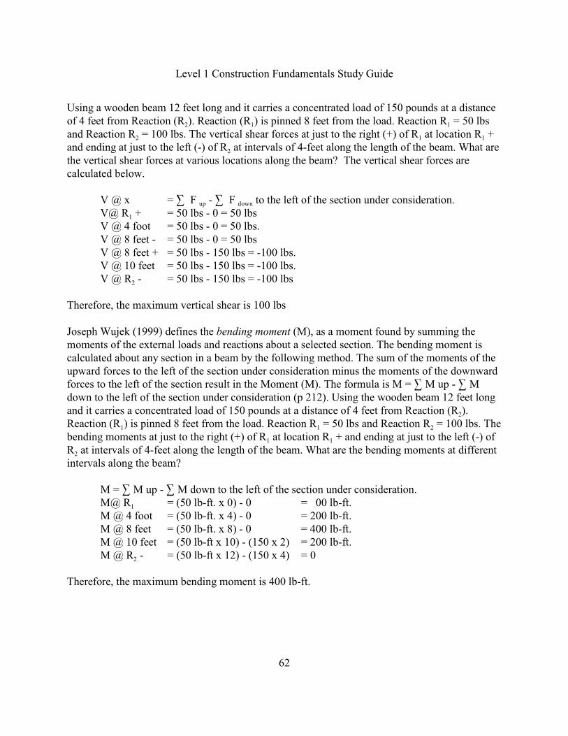
Using a wooden beam 12 feet long and it carries a concentrated load of 150 pounds at a distance
2 1 1of 4 feet from Reaction (R ). Reaction (R ) is pinned 8 feet from the load. Reaction R = 50 lbs
2 1 1and Reaction R = 100 lbs. The vertical shear forces at just to the right (+) of R at location R +
2and ending at just to the left (-) of R at intervals of 4-feet along the length of the beam. What arethe vertical shear forces at various locations along the beam? The vertical shear forces arecalculated below.
up downV @ x = 3 F - 3 F to the left of the section under consideration.
1V@ R + = 50 lbs - 0 = 50 lbsV @ 4 foot = 50 lbs - 0 = 50 lbs.V @ 8 feet - = 50 lbs - 0 = 50 lbsV @ 8 feet + = 50 lbs - 150 lbs = -100 lbs.V @ 10 feet = 50 lbs - 150 lbs = -100 lbs.
2V @ R - = 50 lbs - 150 lbs = -100 lbs
Therefore, the maximum vertical shear is 100 lbs
Joseph Wujek (1999) defines the bending moment (M), as a moment found by summing themoments of the external loads and reactions about a selected section. The bending moment iscalculated about any section in a beam by the following method. The sum of the moments of theupward forces to the left of the section under consideration minus the moments of the downwardforces to the left of the section result in the Moment (M). The formula is M = 3 M up - 3 Mdown to the left of the section under consideration (p 212). Using the wooden beam 12 feet long
2and it carries a concentrated load of 150 pounds at a distance of 4 feet from Reaction (R ).
1 1 2Reaction (R ) is pinned 8 feet from the load. Reaction R = 50 lbs and Reaction R = 100 lbs. The
1 1bending moments at just to the right (+) of R at location R + and ending at just to the left (-) of
2R at intervals of 4-feet along the length of the beam. What are the bending moments at differentintervals along the beam?
M = 3 M up - 3 M down to the left of the section under consideration.
1M@ R = (50 lb-ft. x 0) - 0 = 00 lb-ft.M @ 4 foot = (50 lb-ft. x 4) - 0 = 200 lb-ft.M @ 8 feet = (50 lb-ft. x 8) - 0 = 400 lb-ft.M @ 10 feet = (50 lb-ft x 10) - (150 x 2) = 200 lb-ft.
2M @ R - = (50 lb-ft x 12) - (150 x 4) = 0
Therefore, the maximum bending moment is 400 lb-ft.
Level 1 Construction Fundamentals Study Guide
63
Engineering Materials Exercise
1. Which source or organization promotes a uniform organization system for organizingconstruction materials, specifications and documentation into Divisions and Sections forprojects.
A. Sweet’s Catalog.B. Underwriters Laboratory.C. Construction Specifications Institute.D. American Society for Testing Materials.
2. You are interested in finding all of the manufacturers technical lifting data for apermanent overhead crane that the Contractor will install in a manufacturing facility.What is the name of the Reference source?
A. Sweet’s Catalog.B. Thomas’ Register.C Engineering News Record.D. Crane and Riggers Association.
3. Which organization is engaged in the standardization of technical specifications andtesting methods?
A. Underwriters Laboratories.B. American Standards Association.C. Construction Specifications Institute.D. American Society for Testing Materials.
4. Which organization investigates and tests materials, products, equipment, constructionmethods and construction systems to safeguard against hazards to life and property?
A. Underwriters Laboratories.B. American Standards Association.C. Construction Specifications Institute.D. American Society for Testing Materials.
Level 1 Construction Fundamentals Study Guide
64
Engineering Materials Exercise
5. What are Large stones that are placed at the end of culverts or along the edge of a body ofwater to prevent erosion called?
A. Riprap.B. Impurities.C. Weathering.D. Permeability.
6. What are aggregate particles smaller than the size of a grain of sand called?
A. Riprap.B. Abrasion.C. Impurities.D. Permeability.
7. What is a measure of the ease with which water will flow through an aggregate’s voidscalled?
A. Riprap.B. Impurities.C. Weathering.D. Permeability.
8. What is the aggregate quality of resisting weathering called?
A. Abrasion.B. Adhesion.C. Soundness.D. Permeability.
9. What type of pavement system is subject to abrasion throughout because the pavementcontinuously flexes under the weight of traffic?
A. Asphalt.B. Concrete.C. Gravel road.D. Sandy road
Level 1 Construction Fundamentals Study Guide
65
Engineering Materials Exercise
10. What does a sieve size of No. 40, mean?
A. There are 40 openings per lineal inch.B. There are 40 openings per lineal foot.C. There are 40 inches of surface area.D. There are 1600 inches of surface area.
11. Which sieve size are the aggregates initially placed into for analysis?
A. 4 inches.B. 1/4 inchC. No. 4D. No. 200
12. A gradation chart shows a line with a constant slope which indicates that approximatelythe same amount of material is retained on each successive sieve. What is this gradationcalled?
A. Gap graded.B. Well graded.C. Skip graded.D. Uniform gradation.
13. What is the weight of a Cubic Yard of concrete?
A. 150 poundsB. 1350 poundsC. 2430 poundsD. 4050 pounds
14. What is the term for a material that strains slowly when a force is applied to it for anextended period of years, even though the force is too small to cause failure in a shortperiod of time?
A. Creep.B. Deformation.C. Working stress.D. Allowable stress.
Level 1 Construction Fundamentals Study Guide
66
Engineering Materials Exercise
15. What is the chemical reaction called when Portland cement is mixed with the water?
A. SettingB. Adhesion.C. Hydration.D. Air-entrainment.
16. Which of the following types of soil has high permeability?
A. Clay.B. Gravel.C. Solid Rock.D. Fine Sands & Silts.
17. Which type of Portland cement is used where an early strength gain is important?
A. Type I.B. Type III.C. Type M.D. Type O.
18. Which concrete characteristic is improved by air-entraining the concrete?
A. Strength.B. Hydration.C. Sulfate resistance.D. Freeze-thaw resistance.
19. What is the most important parameter used to control the strength of concrete?
A. Air-entrainment.B. Water/Cement Ratio.C. Type of Portland Cement.D. Coarse/Fine Aggregate Ratio.
Level 1 Construction Fundamentals Study Guide
67
Engineering Materials Exercise
20. What is Air-entrained Portland cement Concrete quite weak in?
A. Tension.B. Durability.C. Compression.D. Bond Strength.
21. Which technical resource must be consulted to determine the bar support spacing for a Concrete Bridge deck?
A. American Concrete Institute.B. Concrete Reinforcing Steel Institute.C. Construction Specifications Institute.D. American Society for Testing Materials.
22. What is the diameter in inches of a #8 bar?
A. 1/8 B. ½C. 1.0D. 8.0
23. What is the weight of a bag of Portland Cement in pounds?
A. 50B. 90C. 120D. 150
24. What is the weight of a #5 deformed bar in pounds?
A. 0.310B. 0.625C. 1.043D. 1.963
Level 1 Construction Fundamentals Study Guide
68
Engineering Materials Exercise
25. Which materials are incorporated by reference and not normally shown on the plans or inthe Technical Specifications?
A. Concrete.B. Bar Supports.C. Reinforcement.D. Welded Wire Fabric.
26. Which type of masonry cement is used where bond and lateral strength are important?
A. Type I.B. Type III.C. Type N.D. Type S.
27. Which type of masonry cement is used for foundation walls and isolated piers?
A. Type K.B. Type N.C. Type O.D. Type S.
28. Which type of masonry cement is used for reinforced masonry?
A. Type K.B. Type N.C. Type O.D. Type S.
29. Which of the following mortar ingredients improves the mortar’s workability?
A. Lime.B. Sand.C. Gravel.D. Portland cement.
Level 1 Construction Fundamentals Study Guide
69
Engineering Materials Exercise
30. Which of the following mortar ingredients decreases the shrinkage of mortar while settingand drying?
A. Lime.B. Sand.C. Water.D. Portland cement.
31. What ingredient is added to mortar for retempering?
A. Lime.B. Sand.C. Water.D. Portland cement.
32. Which mortar property is increased by retempering?
A. Oxidation.B. Bond Strength.C. Weather Resistance.D. Compressive Strength.
33. What is the strongest overlap of masonry units when building a wall?
A. No lap.B. One-quarter lap.C. One-half lap.D. One-third lap.
34. Structural bonding can be accomplished by tying two wythes together with a brick. Whenit is laid in this position, what is the brick position called?
A. Sailor.B. Header.C. Soldier.D. Stretcher.
Level 1 Construction Fundamentals Study Guide
70
Engineering Materials Exercise
35. What is the most common brick position?
A. Shiner.B. Header.C. Rowlock.D. Stretcher.
36. What brick position is commonly used on window sills?
A. Sailor.B. Header.C. Soldier.D. Rowlock.
37. What is the weakest pattern bond?
A. Stack.A. Flemish.B. Running.C. Common.
38. Which of the following masonry components allows freedom of movement in a masonrywall?
A. Bond Beam.B. Control Joint.C. Vertical Joint reinforcement.D. Horizontal Joint reinforcement.
39. Which of the following masonry components are continuous, they may run around theperimeter of a building or between control joints and act as structural members, and theycan provide bearing for beams and joists?
A. Lintels.B. Bond Beam.C. Control Joint.D. Vertical Joint reinforcement.
Level 1 Construction Fundamentals Study Guide
71
Engineering Materials Exercise
40. Which of the following masonry components are used over openings in block walls tocarry the load around the opening?
A. Lintels.B. Bond Beam.C. Control Joint.D. Vertical Joint reinforcement.
41. Which type of wall is desired where there is severe weather exposure, or where amaximum resistance to rain penetration is desired?
A. Cavity.B. Veneer.C. Composite.D. Reinforced Masonry.
42. What does the steel designation C 12 x 20.7 mean?
A. C is the steel shape, 12 is the nominal depth and 20.7 is the pounds per foot.B. C is the steel shape, 12 is the pounds per foot and 20.7 is the nominal depth.C. C is the steel series, 12 is the nominal depth and 20.7 is the pounds per foot.D. C is the flange width series, 12 is the pounds per foot, and 20.7 is the nominal
depth.
43. Which organization publishes structural steel design properties manuals and manuals thatcover steel construction methods?
A. American Welding Society.B. The American Iron and Steel Institute.C. American Society for Testing Materials.D. American Institute of Steel Construction.
44. What are the drawings called that are issued to the contractor from the manufacturerindicating the locations and proper positioning of each piece of steel within the structure?
A. Shop Drawings.B. Erection Drawings.C. Working Drawings.D. Architectural Drawings.
Level 1 Construction Fundamentals Study Guide
72
Engineering Materials Exercise
45. What structural steel component is the steel designation “VL” referring to?
A. Angle.B. Steel Shape.C. Metal Decking.D. Open-web joist.
46. What structural steel component is the steel designation “LH” referring to?
A. Channel.B. Steel Shape.C. Metal Decking.D. Open-web joist.
47. Which of the following is structural steel most susceptible to for failure?
A. Fire.B. Rain.C. Snow.D. Chemical.
48. What is sprayed onto structural steel to increase its fire resistance capability?
A. Paint.B. Creosote.C. Preservative.D. Mineral wool.
49. How is the fireproofing of a steel structure determined?
A. Size.B. Height.C. Occupancy.D. Adjacent structures.

Level 1 Construction Fundamentals Study Guide
73
Engineering Materials Exercise
50. What type of weld fits two pieces of metal together end-to-end for welding?
A. Slot.B. Butt.C. Plug.D. Fillet.
51. Assume you have a fillet weld symbol on the top of the welding symbol arrow. Whichside will the weld be placed on?
A. The ends are welded.B. All sides all the way around.C. Arrow side that it is pointing to.D. Other side from where the arrow is pointing.
52. Assume you have a square weld symbol with a solid flag on a pole coming up from thechange in direction of the arrow. What does the solid backwards flag on a pole tell you?
A. Field weld.B. Flush weld.C. Contour weld.D. Weld all the way around.
53. If the weld is supposed to be on all four sides, what symbol will be used?
A. Circle.B. Single- V.C. Convex.D. Right Triangle.
54. What is the wood member called that is graded according to its bending strength on itsnarrow edge which is 2-4 inches thick and at least 6 inches wide?
A. Joists.B. Planks.C. Boards.D. Timbers.
Level 1 Construction Fundamentals Study Guide
74
Engineering Materials Exercise
55. What is the wood member called that is graded according to its bending strength on itsnarrow edge which is at least 4 inches thick and at least 2 inches wider than they arethick?
A. Planks.B. Light Framing.C. Post and Timbers.D. Beams and Stringers.
56. What is the stress term called that has the narrow dimension carrying the load with thefibers at the top in compression and the bottom fibers are in tension?
A. Modulus of Elasticity (E).
bB. Extreme Fiber Bending (F ).
vC. Horizontal Shear Parallel to the Grain (F //).
cD. Compression Perpendicular to the Grain (F z ).
57. What is the stress term called in a wood frame structure which works in unison to supportthe load on the structure and allows part of the load from a weaker member to bedistributed to adjacent members?
A. Modulus of Elasticity (E).
tB. Tension parallel to the grain (F //)
bC. Extreme Fiber Bending (F ) in a Single member.
bD. Extreme Fiber Bending (F ) in Repetitive members.
58. What is the wood member called that is graded according to its bending strength on itswider dimension which is 2-4 inches thick and at least 6 inches wide?
A. Joists.B. Planks.C. Boards.D. Posts and Timbers.
Level 1 Construction Fundamentals Study Guide
75
Engineering Materials Exercise
59. What is the wood member called that is graded according to its load being are carried onthe cross section?
A. Joists.B. Planks.C. Boards.D. Posts and Timbers.
60. What is the stress term called that is induced by pressing the fiber together longitudinallyon its cross section?
tA. Tension parallel to the grain (F //)
cB. Compression Parallel to the Grain (F //)
vC. Horizontal Shear Parallel to the Grain (F //).
cD. Compression Perpendicular to the Grain (F z ).
61. What is the stress term called that is induced by the tendency for the upper fibers to slideover the lower fibers as a beam bends?
tA. Tension parallel to the grain (F //)
cB. Compression Parallel to the Grain (F //)
vC. Horizontal Shear Parallel to the Grain (F //).
cD. Compression Perpendicular to the Grain (F z ).
62. What is the stress term called which is a measure of the stiffness or resistance todeflection?
A. Modulus of Elasticity (E).
bB. Extreme Fiber Bending (F ).
vC. Horizontal Shear Parallel to the Grain (F //).
cD. Compression Perpendicular to the Grain (F z ).
63. Which of the following values is a typical number for the Modulus of Elasticity (E)?
A. 90B. 800C. 1,800D. 1,300,000
Level 1 Construction Fundamentals Study Guide
76
Engineering Materials Exercise
64. Which of the following soft wood species used for structural lumber have the highestFiber bending and Modulus of Elasticity (E) values?
A. Cedar and Larch.B. Loblolly Pine and Ponderosa Pine.C. White spruce and Western White Pine.D. Douglas Fir and Southern Yellow Pine.
65. Under the structural lumber classification system, What is the name of the top grade?
A. No. 1B. Stud Grade.C. Construction Grade.D. Select Structural Grade.
66. What is the structural lumber grade used where straightness and strength are the mostimportant consideration such as in concrete formwork?
A. No. 1.B. Standard Grade.C. Construction Grade.D. Select Structural Grade.
67. What does the abbreviation of S2S stamp on a piece of lumber mean?
A. Select Two Sides.B. Select Two Edges.C. Smooth Two Sides.D. Smooth Two Edges.
68. What is the moisture content percentage of the lumber stamp abbreviation of S-DRY?
A. 1 B. 8C. Less than 19.D. Greater than 19.
Level 1 Construction Fundamentals Study Guide
77
Engineering Materials Exercise
69. What does the B-B designation plyform refer to?
A. The category classification of lumber.B. The group number of relating to the number of plies.C. The front and back surface plies which have knots up to 1 inch on both sides.D. The front and back surface plies have a solid surface with smooth repair plugs.
70. What is the term for a material that deforms slowly when a force is applied to it for anextended period of years, even though the force is too small to cause failure in a shortperiod of time?
A. Creep.B. Strain.C. Tension.D. Compression.
71. What is the stress term called that when the stress is induced by pulling apart in alongitudinal direction?
tA. Tension parallel to the grain (F //)
cB. Compression Parallel to the Grain (F //)
vC. Horizontal Shear Parallel to the Grain (F //).
cD. Compression Perpendicular to the Grain (F z ).
72. What is the term called that is a measure of its ability to cause turning, rotating ortwisting about an axis of rotation?
A. Tension.B. Moment.C. Vertical Shear.D. Horizontal Shear.
73. What is the term called where the force tends to cause a member to fail by cuttingperpendicular to the beam’s longitudinal axis at or near the beam’s supports?
A. Tension.B. Moment.C. Vertical Shear.D. Horizontal Shear.
Level 1 Construction Fundamentals Study Guide
78
Engineering Materials Exercise
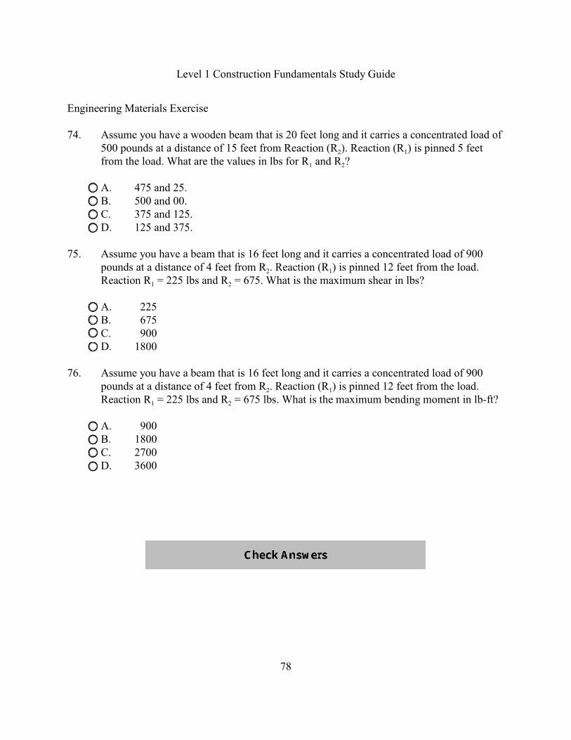
74. Assume you have a wooden beam that is 20 feet long and it carries a concentrated load of
2 1500 pounds at a distance of 15 feet from Reaction (R ). Reaction (R ) is pinned 5 feet
1 2from the load. What are the values in lbs for R and R ?
A. 475 and 25.B. 500 and 00.C. 375 and 125.D. 125 and 375.
75. Assume you have a beam that is 16 feet long and it carries a concentrated load of 900
2 1pounds at a distance of 4 feet from R . Reaction (R ) is pinned 12 feet from the load.
1 2Reaction R = 225 lbs and R = 675. What is the maximum shear in lbs?
A. 225B. 675C. 900D. 1800
76. Assume you have a beam that is 16 feet long and it carries a concentrated load of 900
2 1pounds at a distance of 4 feet from R . Reaction (R ) is pinned 12 feet from the load.
1 2Reaction R = 225 lbs and R = 675 lbs. What is the maximum bending moment in lb-ft?
A. 900B. 1800C. 2700D. 3600
Level 1 Construction Fundamentals Study Guide
79
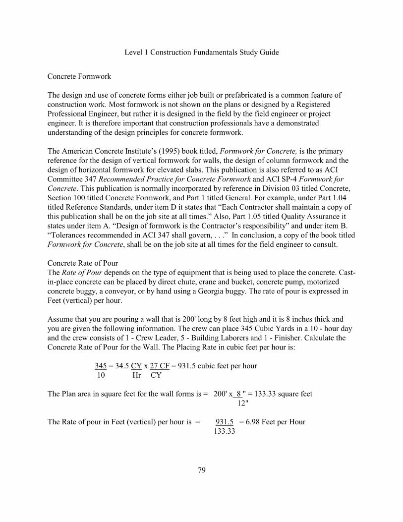
Concrete Formwork
The design and use of concrete forms either job built or prefabricated is a common feature ofconstruction work. Most formwork is not shown on the plans or designed by a RegisteredProfessional Engineer, but rather it is designed in the field by the field engineer or projectengineer. It is therefore important that construction professionals have a demonstratedunderstanding of the design principles for concrete formwork.
The American Concrete Institute’s (1995) book titled, Formwork for Concrete, is the primaryreference for the design of vertical formwork for walls, the design of column formwork and thedesign of horizontal formwork for elevated slabs. This publication is also referred to as ACICommittee 347 Recommended Practice for Concrete Formwork and ACI SP-4 Formwork forConcrete. This publication is normally incorporated by reference in Division 03 titled Concrete,Section 100 titled Concrete Formwork, and Part 1 titled General. For example, under Part 1.04titled Reference Standards, under item D it states that “Each Contractor shall maintain a copy ofthis publication shall be on the job site at all times.” Also, Part 1.05 titled Quality Assurance itstates under item A. “Design of formwork is the Contractor’s responsibility” and under item B.“Tolerances recommended in ACI 347 shall govern, . . .” In conclusion, a copy of the book titled Formwork for Concrete, shall be on the job site at all times for the field engineer to consult.
Concrete Rate of PourThe Rate of Pour depends on the type of equipment that is being used to place the concrete. Cast-in-place concrete can be placed by direct chute, crane and bucket, concrete pump, motorizedconcrete buggy, a conveyor, or by hand using a Georgia buggy. The rate of pour is expressed inFeet (vertical) per hour.
Assume that you are pouring a wall that is 200' long by 8 feet high and it is 8 inches thick andyou are given the following information. The crew can place 345 Cubic Yards in a 10 - hour dayand the crew consists of 1 - Crew Leader, 5 - Building Laborers and 1 - Finisher. Calculate theConcrete Rate of Pour for the Wall. The Placing Rate in cubic feet per hour is:
345 = 34.5 CY x 27 CF = 931.5 cubic feet per hour 10 Hr CY
The Plan area in square feet for the wall forms is = 200' x 8 " = 133.33 square feet 12"
The Rate of pour in Feet (vertical) per hour is = 931.5 = 6.98 Feet per Hour 133.33
Level 1 Construction Fundamentals Study Guide
80
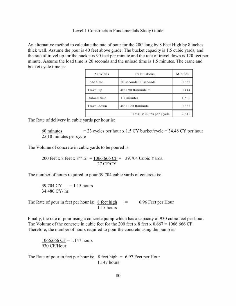
An alternative method to calculate the rate of pour for the 200' long by 8 Feet High by 8 inchesthick wall. Assume the pour is 40 feet above grade. The bucket capacity is 1.5 cubic yards, andthe rate of travel up for the bucket is 90 feet per minute and the rate of travel down is 120 feet perminute. Assume the load time is 20 seconds and the unload time is 1.5 minutes. The crane andbucket cycle time is:
Activities Calculations Minutes
Load time 20 seconds/60 seconds 0.333
Travel up 40' / 90 ft/minute = 0.444
Unload time 1.5 minutes 1.500
Travel down 40' / 120 ft/minute 0.333
Total Minutes per Cycle 2.610
The Rate of delivery in cubic yards per hour is:
60 minutes = 23 cycles per hour x 1.5 CY bucket/cycle = 34.48 CY per hour2.610 minutes per cycle
The Volume of concrete in cubic yards to be poured is:
200 feet x 8 feet x 8"/12" = 1066.666 CF = 39.704 Cubic Yards.27 CF/CY
The number of hours required to pour 39.704 cubic yards of concrete is:
39.704 CY = 1.15 hours34.480 CY/ hr.
The Rate of pour in feet per hour is: 8 feet high = 6.96 Feet per Hour1.15 hours
Finally, the rate of pour using a concrete pump which has a capacity of 930 cubic feet per hour.The Volume of the concrete in cubic feet for the 200 feet x 8 feet x 0.667 = 1066.666 CF.Therefore, the number of hours required to pour the concrete using the pump is:
1066.666 CF = 1.147 hours930 CF/Hour
The Rate of pour in feet per hour is: 8 feet high = 6.97 Feet per Hour1.147 hours
Level 1 Construction Fundamentals Study Guide
81
Lateral Concrete Pressure on Wall FormsThe Lateral Concrete Pressure exerted on vertical formwork is affected by several factors. First,the freshly placed concrete initially acts as a fluid exerting hydrostatic pressure against thevertical formwork. Second, the weight of the concrete exerts pressure on the forms and concreteis assumed to weigh between 150 and 154 pounds per cubic foot. Third, the placement rate ofconcrete affects the lateral pressure. The greater the height of the wall allows the concrete tobehave as a fluid which has a greater lateral pressure at the bottom. Fourth, The temperature ofthe concrete and the atmospheric conditions affect the setting time which affects the pressure onthe forms. Fifth, vibration of the concrete increases the lateral pressure because the concrete actsas a fluid for the full depth being vibrated. Sixth, the consistency of the concrete mix affects thelateral pressure. In conclusion, the lateral concrete pressure is a function of the hydrostaticpressure, the weight of the concrete, the rate of the pour, the temperature of the concrete, theconsolidation of concrete by vibration and the consistency of the concrete mix all effect thelateral concrete pressure.
The ACI 347 Committee has developed the following formulas for calculating the maximumlateral pressure (p) for the design of wall forms. The lateral pressure (p) is expressed in poundsper square foot (psf). The ACI 347 Committee also insists that these formulas were developed forvery specific conditions. The basic lateral pressure formulas for the wall forms are based uponthe following placement conditions. The concrete is made with a Type I cement weighing 150pounds per cubic foot, containing no pozzolans or admixtures, with a maximum slump of 4inches. The internal vibration is limited to a depth of 4 feet or less below the concrete surface,and the maximum rate of pour cannot exceed 10 feet per hour (p 5-12). The ACI 347 Committeerecommends these formulas with limitations for the lateral pressure on wall forms as follows. ForWalls with placement rates of less than 7 feet per hour, the pressure is:
p = 150 + 9000RT
For Wall with placement rates of 7 feet per hour and up to10 feet per hour, the pressure is: p = 150+ 43,400 + 2800 R
T T
The abbreviations in the formulas represent the following units:p = lateral pressure in pounds per square foot (psf)R = the rate of concrete placement in feet per hourT = the temperature of the concrete in the form, in degrees Fahrenheit.
Finally, the lateral pressure on the wall forms is limited as follows. The Maximum pressure is2000 psf but in no case greater than 150 times the height of the wall, whichever is less. This isexpressed as p = 150h. The minimum pressure is 600 psf.

Level 1 Construction Fundamentals Study Guide
82
An example of the maximum lateral concrete pressure for the design of wall forms for a 12-foothigh wall that will be placed at 5 feet per hour. The temperature of the concrete at the time of thepour will be 75F. Also, Type 1 cement was used without admixtures, and the slump with this mixis typically 4 inches or less. The top 3 feet of the concrete must be vibrated according to thespecifications. For this case, the maximum fluid pressure is calculated under the assumption thatthe unit weight of the concrete will be approximately 150 pounds per cubic foot (pcf). Therefore,for walls with a placement rate of less than 7 feet per hour, the maximum pressure is:
p = 150 + 9000RT
p = 150 + 9000 (5) = 750 psf75
Check for maximum pressure: the lesser of 2,000 psf and 150h, whichever is less:
p = 150h = 150 (12) = 1800 psf
In this example, use the formula value of 750 psf because the conditions for the placement of theconcrete match the assumptions for the rate of placement formula, so that this maximum will bereduced by the initial set within the lower portions of the concrete.
This pressure will build up as a fluid pressure based on the 150 pounds per cubic foot (pcf) unitweight of the fluid. To determine the height of the maximum pressure, the 150h represents thepressure of concrete in its liquid state which can be equated to the maximum pressure calculated.The formula is p = 150h which can be expressed in terms of the distance (h) from the top of theconcrete pour as:
h = p150
The h represents the distance from the top of the concrete pour to where the calculated maximumpressure begins. In this example, the distance from the top of the pour to the point of maximumpressure is:
h = 750 psf = 5 feet150 p
Level 1 Construction Fundamentals Study Guide
83
Lateral Concrete Pressure on Column Forms The ACI 347 Committee has also developed the following formula for calculating the maximumlateral pressure for the design of column forms. The lateral pressure is expressed in pounds persquare foot (psf). The ACI 347 Committee also insists that the column formula was developedfor very specific conditions. The basic lateral pressure formula for the column forms is basedupon the following placement conditions which are similar to the wall form formula. Theconcrete is made with a Type I cement weighing 150 pounds per cubic foot, containing nopozzolans or admixtures, with a maximum slump of 4 inches. The internal vibration is limited toa depth of 4 feet or less below the concrete surface (p 5-13).
The ACI 347 Committee states that the column forms are small enough that the concrete isfrequently placed to their full height within the time that it takes the concrete to begin to set. Also, the vibration of the concrete frequently extends the full height of the form which results ingreater maximum lateral pressures than those that occur in wall forms. Therefore, the pressure incolumn forms is essentially a fluid (p 5-13). The ACI 347 Committee recommends this formulawith limitations for the lateral pressure on columns as follows:
For Columns, where the maximum height of a single lift of concrete for the pour does not exceed18 feet per hour, the pressure is:
p = 150 + 9000RT
Finally, the lateral pressure on the column forms is limited as follows. The Maximum pressure is3000 psf but in no case greater than 150 times the height of the column, whichever is less. This isexpressed as p = 150h. The minimum pressure is 600 psf.
An example of the maximum lateral concrete pressure for the design of column forms given thefollowing conditions is shown below.
Height of column = 15 Feet Rate of pour (R) = 10 Feet per hourConcrete Temperature (T) = 40 Degrees Fahrenheit
For columns, the maximum concrete pressure on the column is?
p = 150 + 9000 10 = 2400 psf 40
Check for maximum pressure: the lesser of 3000 psf and 150h = 150 x 15= 2250 psf. Therefore,in this example, use the 150h = 2250 psf as the maximum pressure instead of the formula value.
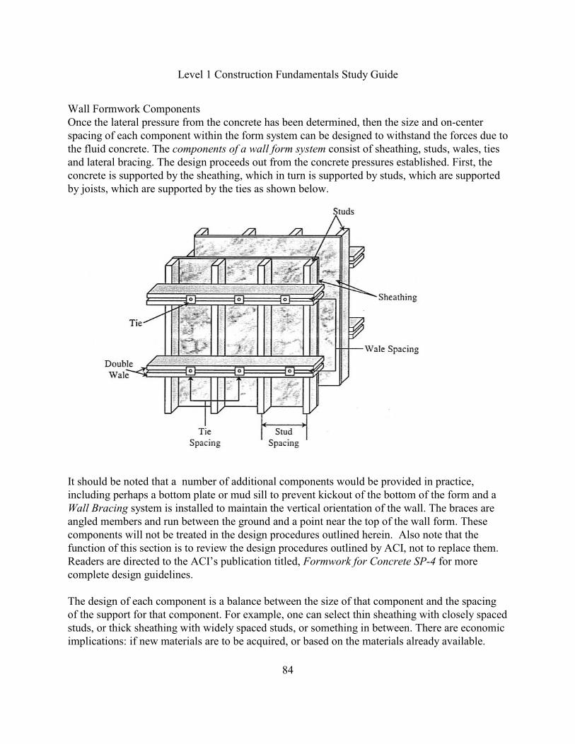
Level 1 Construction Fundamentals Study Guide
84
Wall Formwork ComponentsOnce the lateral pressure from the concrete has been determined, then the size and on-centerspacing of each component within the form system can be designed to withstand the forces due tothe fluid concrete. The components of a wall form system consist of sheathing, studs, wales, tiesand lateral bracing. The design proceeds out from the concrete pressures established. First, theconcrete is supported by the sheathing, which in turn is supported by studs, which are supportedby joists, which are supported by the ties as shown below.
It should be noted that a number of additional components would be provided in practice,including perhaps a bottom plate or mud sill to prevent kickout of the bottom of the form and aWall Bracing system is installed to maintain the vertical orientation of the wall. The braces areangled members and run between the ground and a point near the top of the wall form. Thesecomponents will not be treated in the design procedures outlined herein. Also note that thefunction of this section is to review the design procedures outlined by ACI, not to replace them.Readers are directed to the ACI’s publication titled, Formwork for Concrete SP-4 for morecomplete design guidelines.
The design of each component is a balance between the size of that component and the spacingof the support for that component. For example, one can select thin sheathing with closely spacedstuds, or thick sheathing with widely spaced studs, or something in between. There are economicimplications: if new materials are to be acquired, or based on the materials already available.

Level 1 Construction Fundamentals Study Guide
85
Plyform Sheathing and Sheathing TablesSheathing is the material in contact with the concrete. The most common sheathing material forjob-built formwork is plyform. The American Plywood Association (APA) defines plyform as acomposite material made by gluing together thin layers or plies of wood. The quality of the pliesused for the surface has an impact on the smoothness of the concrete surface. Plyform forconcrete is graded B-B which is sanded smooth with some plugs allowed. The Plyform strengthis given by its Class; most plyform is Class 1 which is the stronger class. The grain direction isalternated in each layer to provide resistance to warping and curling of the plywood. In theUnited States, the plyform is made with an odd number of layers so that there is one more layerwith its grain in the same direction as the face grain than there is perpendicular to that directionas shown below.
Plywood Grain Directions
As a result, the plywood is stronger when the face grain runs in the direction of the span. Sincethe sheathing “spans” from stud to stud, the plywood is usually used with the face grain runningfrom one stud to the next, rather than parallel to the studs. This orientation is called “face grainparallel to the span.” In the United States the plywood and the plyform is made with the facegrain parallel to the long dimension of the plywood.
The American Concrete Institute (ACI) has calculated the safe spans for numerous formworkcomponents and developed a series of formwork tables that provide the field engineer with aquick method for selecting the appropriate spacing for the material sizes available. The tableshave been arranged into four groups. Tables 7-2, 7-3 and 7-4 are called plywood sheathing tablesand they are utilized to determine the maximum stud spacing. Tables 7-5, 7-6, 7-7 are calledjoists, studs, stringers or any other beam components of the formwork where the framingmembers are used singly. The joist tables are used to determine the maximum wale spacing.Tables 7-8, 7-9, 7-10 are called double wale tables where the members are used double. The waletables are used to determine the maximum allowable wall tie spacing.
In summary, the design of a wall form system uses plywood sheathing tables 7-2, 7-3 and 7-4 todetermine the stud spacing. It uses the joist, stud, and stringer tables 7-5, 7-6, 7-7 to determinethe wale spacing and it uses the double wale tables 7-8, 7-9, 7-10 to determine the maximumwall tie spacing.

Level 1 Construction Fundamentals Study Guide
86
Maximum Allowable Stud SpacingThe formwork design process begins with the selected sheathing and the tables are used todetermine the maximum stud spacing. It is common to start with an assumed sheathing thickness,and with that thickness to calculate a stud spacing. The stud spacing comes from the ACI’sPlywood Sheathing Design Tables 7-2, 7-3 and 7-4. They are for plyform sheathing utilized inthe construction of walls, columns and elevated slabs. These tables cover three different loadsituations. Table 7-2 is titled Safe Spacing, in Inches, of Supports for Plywood Sheathing,Continuous over Four or More Supports (p 7-7). Table 7-3 is titled, Safe Spacing, in Inches, ofSupports for Plywood Sheathing, Continuous over Two Spans (p 7-8). Table 7-4 is titled SafeSpacing, in Inches, of Supports for Plywood Sheathing with only two points of support (p 7-9).The continuous over many spans approach is usually assumed, because ordinarily there are atmost 24” spacing over the 8-foot side of the plywood; hence, there will be at least four spans.
To use the sheathing design tables 7-2, 7-3 or 7-4, first calculate the maximum concrete pressure.Then, select a sheathing thickness, and decide whether the loading will be short term or longterm. Short term loading is often referred to as a single use. Long term loading is often referred toas forms that will be used several times. The Sheathing Design Tables 7-2, 7-3 and 7-4 werecalculated for both short term and long term using the working stresses for Class 1 concreteplyform. The tables contain the concrete pressures down the left-hand side. Horizontally, thetable is divided into two halves by the vertical double line. The values to the left of this doublevertical line are the short term loads and the values to the right of the double vertical line are thelong-term loads. The long term loading is the more common in practice.
bThe Sheathing Design Tables also contain the parameters for the allowable bending stress (F’ ),the rolling shear, and the allowable design value for the modulus of elasticity (E’) using B-B
bClass 1 Plyform. The allowable bending stress (F’ ) is either 1930 psi or 1545 psi. The rollingshear is either 72 psi or 57 psi. The allowable modulus of elasticity (E’) is 1,500,000. Next, thedesigner must consider the orientation of the plywood and make a selection of which of the twocolumns on each side of the double line will be used. The orientation of the plywood options oneach side of the double line is Face grain parallel to the span and Face grain perpendicular to thespan. Face grain parallel to the span is more common, but the Face grain perpendicularorientation is sometimes used. After determining the proper portion of the table, it is a matter offinding the intersection of the column for the sheathing thickness and the row for the maximumexpected pressure. The intersection will be the maximum allowable spacing of the studs. Anexample for determining the maximum allowable spacing of studs for a wall form system basedupon the following conditions is:
Concrete pressure: 750 psf.
Stud Support Conditions: Continuous over 3 or more spansLoading Duration: Short termSheathing: 1" B-B Class 1 Plyform, Face Grain Parallel to Span
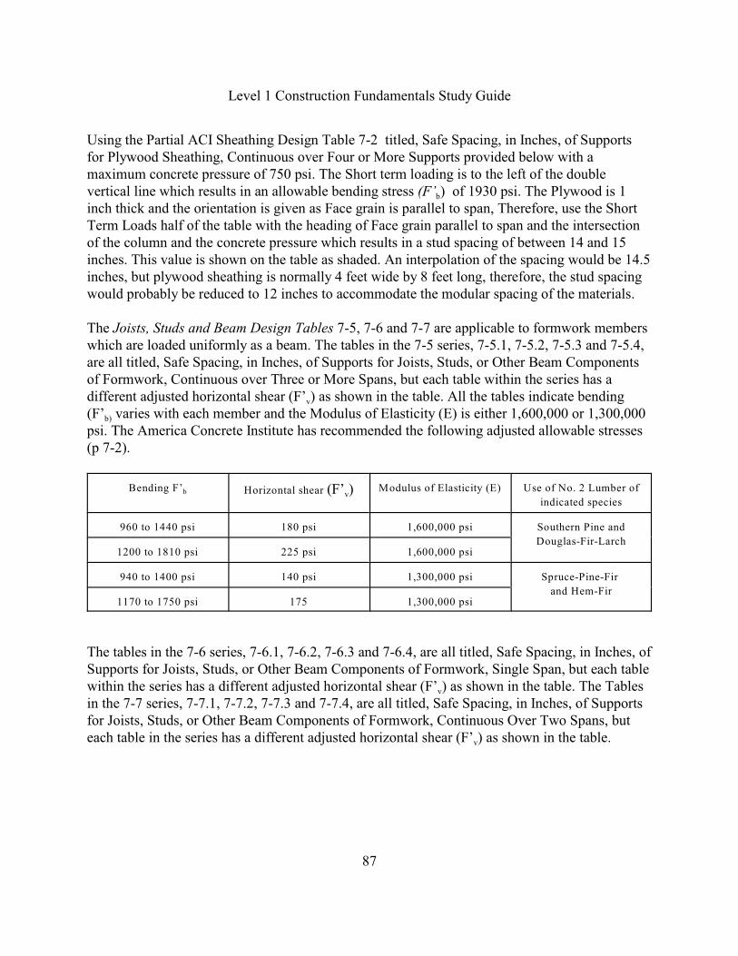
Level 1 Construction Fundamentals Study Guide
87
Using the Partial ACI Sheathing Design Table 7-2 titled, Safe Spacing, in Inches, of Supportsfor Plywood Sheathing, Continuous over Four or More Supports provided below with amaximum concrete pressure of 750 psi. The Short term loading is to the left of the double
bvertical line which results in an allowable bending stress (F’ ) of 1930 psi. The Plywood is 1inch thick and the orientation is given as Face grain is parallel to span, Therefore, use the ShortTerm Loads half of the table with the heading of Face grain parallel to span and the intersectionof the column and the concrete pressure which results in a stud spacing of between 14 and 15inches. This value is shown on the table as shaded. An interpolation of the spacing would be 14.5inches, but plywood sheathing is normally 4 feet wide by 8 feet long, therefore, the stud spacingwould probably be reduced to 12 inches to accommodate the modular spacing of the materials.
The Joists, Studs and Beam Design Tables 7-5, 7-6 and 7-7 are applicable to formwork memberswhich are loaded uniformly as a beam. The tables in the 7-5 series, 7-5.1, 7-5.2, 7-5.3 and 7-5.4,are all titled, Safe Spacing, in Inches, of Supports for Joists, Studs, or Other Beam Componentsof Formwork, Continuous over Three or More Spans, but each table within the series has a
vdifferent adjusted horizontal shear (F’ ) as shown in the table. All the tables indicate bending
b)(F’ varies with each member and the Modulus of Elasticity (E) is either 1,600,000 or 1,300,000psi. The America Concrete Institute has recommended the following adjusted allowable stresses(p 7-2).
bBending F’vHorizontal shear (F’ ) Modulus of Elasticity (E) Use of No. 2 Lumber of
indicated species
960 to 1440 psi 180 psi 1,600,000 psi Southern Pine and
Douglas-Fir-Larch1200 to 1810 psi 225 psi 1,600,000 psi
940 to 1400 psi 140 psi 1,300,000 psi Spruce-Pine-Fir
and Hem-Fir1170 to 1750 psi 175 1,300,000 psi
The tables in the 7-6 series, 7-6.1, 7-6.2, 7-6.3 and 7-6.4, are all titled, Safe Spacing, in Inches, ofSupports for Joists, Studs, or Other Beam Components of Formwork, Single Span, but each table
vwithin the series has a different adjusted horizontal shear (F’ ) as shown in the table. The Tablesin the 7-7 series, 7-7.1, 7-7.2, 7-7.3 and 7-7.4, are all titled, Safe Spacing, in Inches, of Supportsfor Joists, Studs, or Other Beam Components of Formwork, Continuous Over Two Spans, but
veach table in the series has a different adjusted horizontal shear (F’ ) as shown in the table.
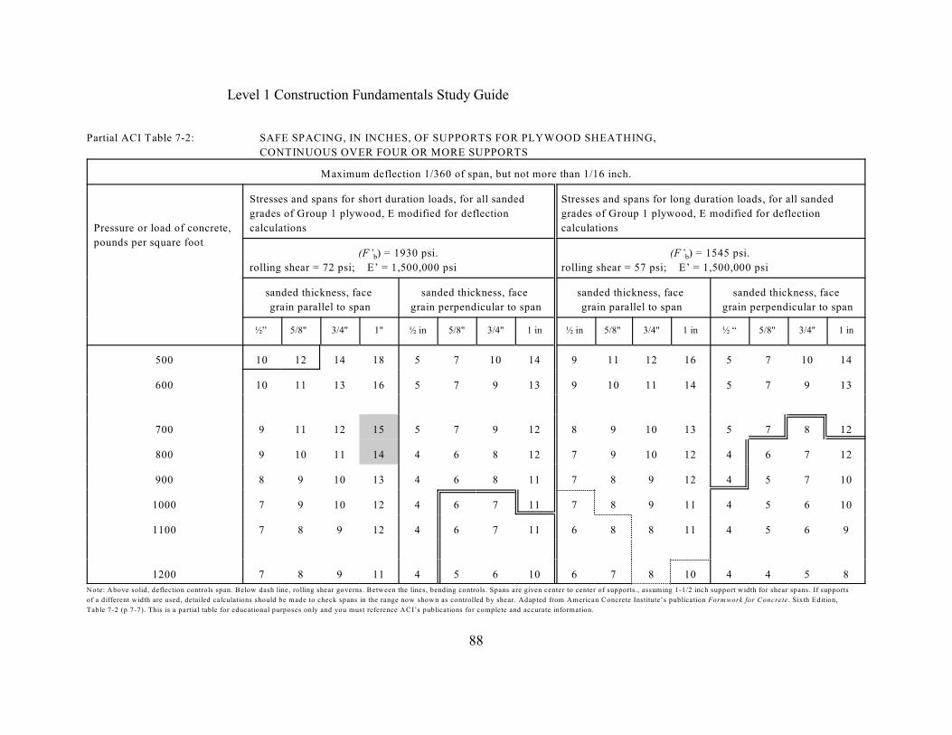
Level 1 Construction Fundamentals Study Guide
88
Partial ACI Table 7-2: SAFE SPACING, IN INCHES, OF SUPPORTS FOR PLYWOOD SHEATHING,
CONTINUOUS OVER FOUR OR MORE SUPPORTS
Maximum deflection 1/360 of span, but not more than 1/16 inch.
Pressure or load of concrete,
pounds per square foot
Stresses and spans for short duration loads, for all sanded
grades of Group 1 plywood, E modified for deflection
calculations
Stresses and spans for long duration loads, for all sanded
grades of Group 1 plywood, E modified for deflection
calculations
b(F’ ) = 1930 psi.
rolling shear = 72 psi; E’ = 1,500,000 psib(F’ ) = 1545 psi.
rolling shear = 57 psi; E’ = 1,500,000 psi
sanded thickness, face
grain parallel to span
sanded thickness, face
grain perpendicular to span
sanded thickness, face
grain parallel to span
sanded thickness, face
grain perpendicular to span
½” 5/8" 3/4" 1" ½ in 5/8" 3/4" 1 in ½ in 5/8" 3/4" 1 in ½ “ 5/8" 3/4" 1 in
500 10 12 14 18 5 7 10 14 9 11 12 16 5 7 10 14
600 10 11 13 16 5 7 9 13 9 10 11 14 5 7 9 13
700 9 11 12 15 5 7 9 12 8 9 10 13 5 7 8 12
800 9 10 11 14 4 6 8 12 7 9 10 12 4 6 7 12
900 8 9 10 13 4 6 8 11 7 8 9 12 4 5 7 10
1000 7 9 10 12 4 6 7 11 7 8 9 11 4 5 6 10
1100 7 8 9 12 4 6 7 11 6 8 8 11 4 5 6 9
1200 7 8 9 11 4 5 6 10 6 7 8 10 4 4 5 8
Note: Above solid, deflection controls span. Below dash line, rolling shear governs. Between the lines, bending controls. Spans are given center to center of supports., assuming 1-1/2 inch support width for shear spans. If supports
of a different width are used, detailed calculations should be made to check spans in the range now shown as controlled by shear. Adapted from American Concrete Institute’s publication Formwork for Concrete. Sixth Edition,
Table 7-2 (p 7-7). This is a partial table for educational purposes only and you must reference ACI’s publications for complete and accurate information.
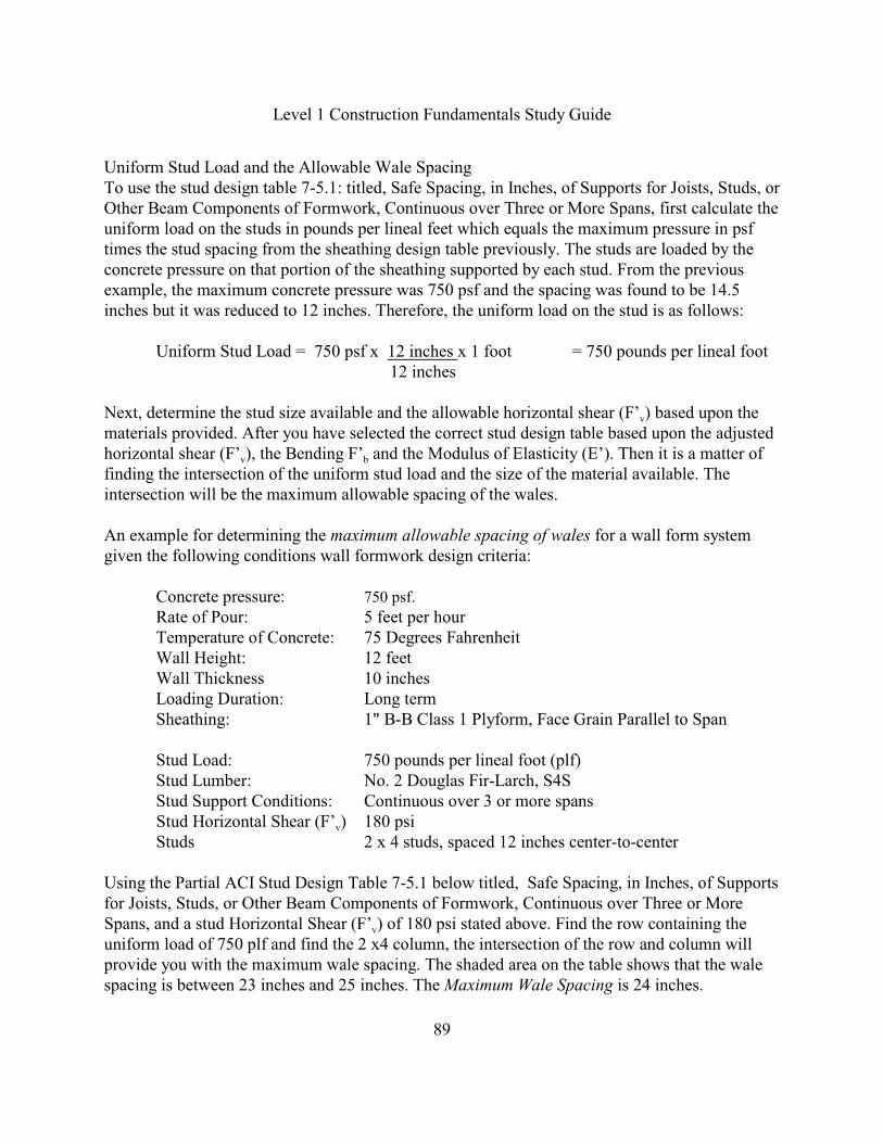
Level 1 Construction Fundamentals Study Guide
89
Uniform Stud Load and the Allowable Wale SpacingTo use the stud design table 7-5.1: titled, Safe Spacing, in Inches, of Supports for Joists, Studs, orOther Beam Components of Formwork, Continuous over Three or More Spans, first calculate theuniform load on the studs in pounds per lineal feet which equals the maximum pressure in psftimes the stud spacing from the sheathing design table previously. The studs are loaded by theconcrete pressure on that portion of the sheathing supported by each stud. From the previousexample, the maximum concrete pressure was 750 psf and the spacing was found to be 14.5inches but it was reduced to 12 inches. Therefore, the uniform load on the stud is as follows:
Uniform Stud Load = 750 psf x 12 inches x 1 foot = 750 pounds per lineal foot 12 inches
vNext, determine the stud size available and the allowable horizontal shear (F’ ) based upon thematerials provided. After you have selected the correct stud design table based upon the adjusted
v bhorizontal shear (F’ ), the Bending F’ and the Modulus of Elasticity (E’). Then it is a matter offinding the intersection of the uniform stud load and the size of the material available. Theintersection will be the maximum allowable spacing of the wales.
An example for determining the maximum allowable spacing of wales for a wall form systemgiven the following conditions wall formwork design criteria:
Concrete pressure: 750 psf.
Rate of Pour: 5 feet per hourTemperature of Concrete: 75 Degrees FahrenheitWall Height: 12 feetWall Thickness 10 inchesLoading Duration: Long termSheathing: 1" B-B Class 1 Plyform, Face Grain Parallel to Span
Stud Load: 750 pounds per lineal foot (plf)Stud Lumber: No. 2 Douglas Fir-Larch, S4SStud Support Conditions: Continuous over 3 or more spans
vStud Horizontal Shear (F’ ) 180 psiStuds 2 x 4 studs, spaced 12 inches center-to-center
Using the Partial ACI Stud Design Table 7-5.1 below titled, Safe Spacing, in Inches, of Supportsfor Joists, Studs, or Other Beam Components of Formwork, Continuous over Three or More
vSpans, and a stud Horizontal Shear (F’ ) of 180 psi stated above. Find the row containing theuniform load of 750 plf and find the 2 x4 column, the intersection of the row and column willprovide you with the maximum wale spacing. The shaded area on the table shows that the walespacing is between 23 inches and 25 inches. The Maximum Wale Spacing is 24 inches.
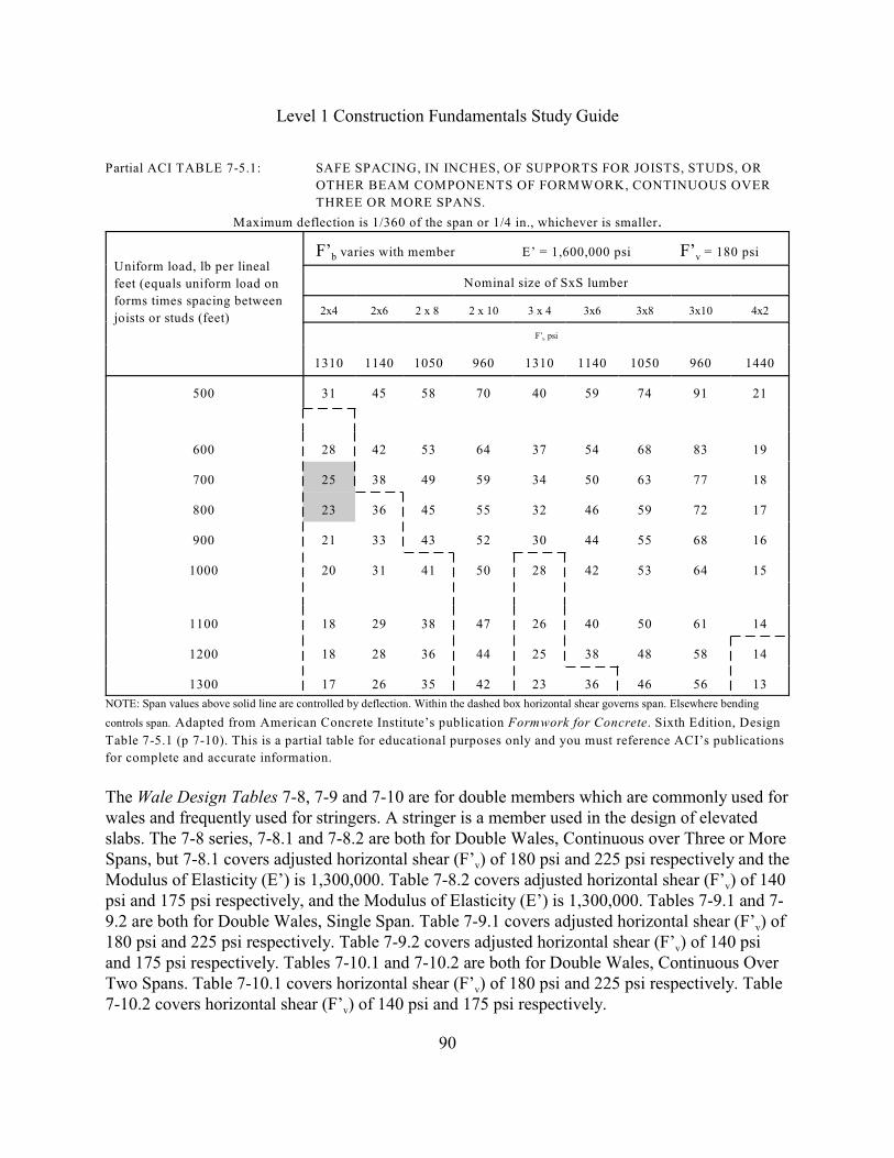
Level 1 Construction Fundamentals Study Guide
90
Partial ACI TABLE 7-5.1: SAFE SPACING, IN INCHES, OF SUPPORTS FOR JOISTS, STUDS, OR
OTHER BEAM COMPONENTS OF FORMWORK, CONTINUOUS OVER
THREE OR MORE SPANS.
Maximum deflection is 1/360 of the span or 1/4 in., whichever is smaller.
Uniform load, lb per lineal
feet (equals uniform load on
forms times spacing between
joists or studs (feet)
b v F’ varies with member E’ = 1,600,000 psi F’ = 180 psi
Nominal size of SxS lumber
2x4 2x6 2 x 8 2 x 10 3 x 4 3x6 3x8 3x10 4x2
bF’ psi
1310 1140 1050 960 1310 1140 1050 960 1440
500 31 45 58 70 40 59 74 91 21
600 28 42 53 64 37 54 68 83 19
700 25 38 49 59 34 50 63 77 18
800 23 36 45 55 32 46 59 72 17
900 21 33 43 52 30 44 55 68 16
1000 20 31 41 50 28 42 53 64 15
1100 18 29 38 47 26 40 50 61 14
1200 18 28 36 44 25 38 48 58 14
1300 17 26 35 42 23 36 46 56 13
NOTE: Span values above solid line are controlled by deflection. Within the dashed box horizontal shear governs span. Elsewhere bending
controls span. Adapted from American Concrete Institute’s publication Formwork for Concrete. Sixth Edition, Design
Table 7-5.1 (p 7-10). This is a partial table for educational purposes only and you must reference ACI’s publications
for complete and accurate information.
The Wale Design Tables 7-8, 7-9 and 7-10 are for double members which are commonly used forwales and frequently used for stringers. A stringer is a member used in the design of elevatedslabs. The 7-8 series, 7-8.1 and 7-8.2 are both for Double Wales, Continuous over Three or More
vSpans, but 7-8.1 covers adjusted horizontal shear (F’ ) of 180 psi and 225 psi respectively and the
vModulus of Elasticity (E’) is 1,300,000. Table 7-8.2 covers adjusted horizontal shear (F’ ) of 140psi and 175 psi respectively, and the Modulus of Elasticity (E’) is 1,300,000. Tables 7-9.1 and 7-
v9.2 are both for Double Wales, Single Span. Table 7-9.1 covers adjusted horizontal shear (F’ ) of
v180 psi and 225 psi respectively. Table 7-9.2 covers adjusted horizontal shear (F’ ) of 140 psiand 175 psi respectively. Tables 7-10.1 and 7-10.2 are both for Double Wales, Continuous Over
vTwo Spans. Table 7-10.1 covers horizontal shear (F’ ) of 180 psi and 225 psi respectively. Table
v7-10.2 covers horizontal shear (F’ ) of 140 psi and 175 psi respectively.
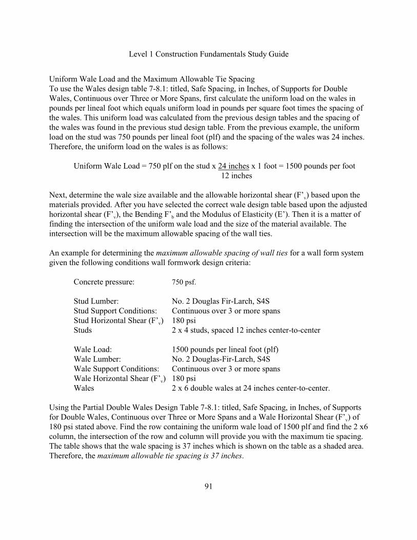
Level 1 Construction Fundamentals Study Guide
91
Uniform Wale Load and the Maximum Allowable Tie SpacingTo use the Wales design table 7-8.1: titled, Safe Spacing, in Inches, of Supports for DoubleWales, Continuous over Three or More Spans, first calculate the uniform load on the wales inpounds per lineal foot which equals uniform load in pounds per square foot times the spacing ofthe wales. This uniform load was calculated from the previous design tables and the spacing ofthe wales was found in the previous stud design table. From the previous example, the uniformload on the stud was 750 pounds per lineal foot (plf) and the spacing of the wales was 24 inches.Therefore, the uniform load on the wales is as follows:
Uniform Wale Load = 750 plf on the stud x 24 inches x 1 foot = 1500 pounds per foot 12 inches
vNext, determine the wale size available and the allowable horizontal shear (F’ ) based upon thematerials provided. After you have selected the correct wale design table based upon the adjusted
v bhorizontal shear (F’ ), the Bending F’ and the Modulus of Elasticity (E’). Then it is a matter offinding the intersection of the uniform wale load and the size of the material available. Theintersection will be the maximum allowable spacing of the wall ties.
An example for determining the maximum allowable spacing of wall ties for a wall form systemgiven the following conditions wall formwork design criteria:
Concrete pressure: 750 psf.
Stud Lumber: No. 2 Douglas Fir-Larch, S4SStud Support Conditions: Continuous over 3 or more spans
vStud Horizontal Shear (F’ ) 180 psiStuds 2 x 4 studs, spaced 12 inches center-to-center
Wale Load: 1500 pounds per lineal foot (plf)Wale Lumber: No. 2 Douglas-Fir-Larch, S4SWale Support Conditions: Continuous over 3 or more spans
vWale Horizontal Shear (F’ ) 180 psiWales 2 x 6 double wales at 24 inches center-to-center.
Using the Partial Double Wales Design Table 7-8.1: titled, Safe Spacing, in Inches, of Supports
vfor Double Wales, Continuous over Three or More Spans and a Wale Horizontal Shear (F’ ) of180 psi stated above. Find the row containing the uniform wale load of 1500 plf and find the 2 x6column, the intersection of the row and column will provide you with the maximum tie spacing.The table shows that the wale spacing is 37 inches which is shown on the table as a shaded area.Therefore, the maximum allowable tie spacing is 37 inches.
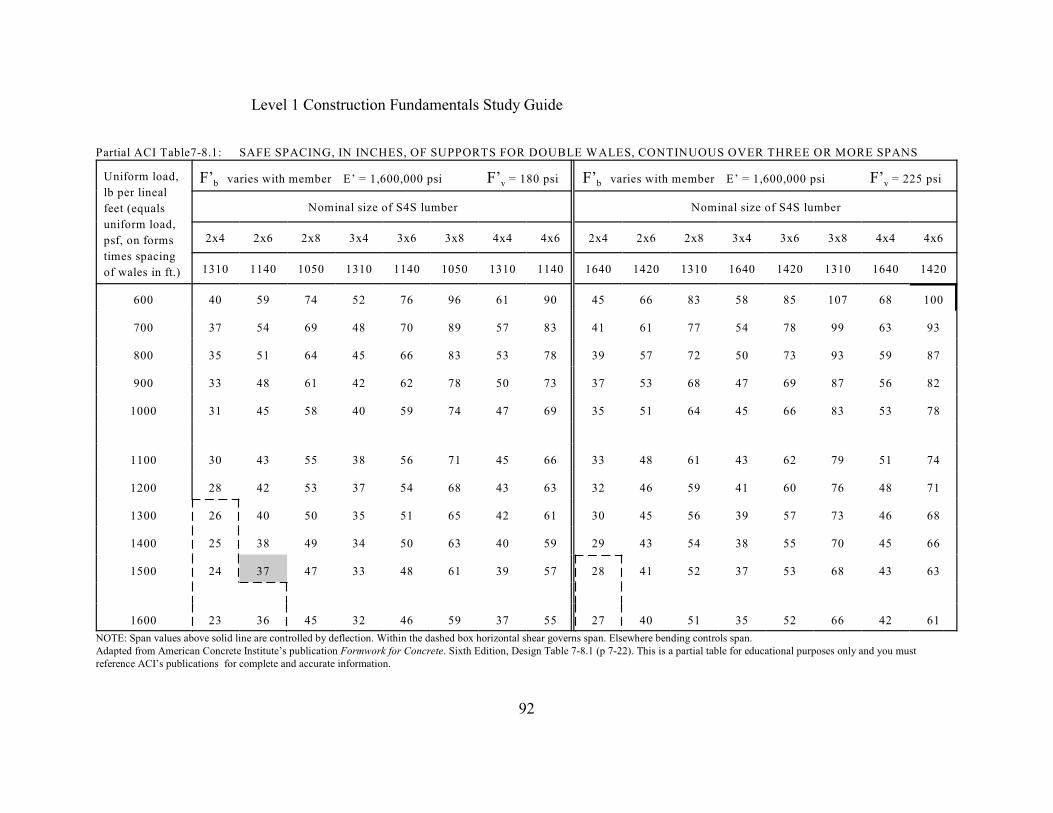
Level 1 Construction Fundamentals Study Guide
92
Partial ACI Table7-8.1: SAFE SPACING, IN INCHES, OF SUPPORTS FOR DOUBLE WALES, CONTINUOUS OVER THREE OR MORE SPANS
Uniform load,
lb per lineal
feet (equals
uniform load,
psf, on forms
times spacing
of wales in ft.)
b v b vF’ varies with member E’ = 1,600,000 psi F’ = 180 psi F’ varies with member E’ = 1,600,000 psi F’ = 225 psi
Nominal size of S4S lumber Nominal size of S4S lumber
2x4 2x6 2x8 3x4 3x6 3x8 4x4 4x6 2x4 2x6 2x8 3x4 3x6 3x8 4x4 4x6
1310 1140 1050 1310 1140 1050 1310 1140 1640 1420 1310 1640 1420 1310 1640 1420
600 40 59 74 52 76 96 61 90 45 66 83 58 85 107 68 100
700 37 54 69 48 70 89 57 83 41 61 77 54 78 99 63 93
800 35 51 64 45 66 83 53 78 39 57 72 50 73 93 59 87
900 33 48 61 42 62 78 50 73 37 53 68 47 69 87 56 82
1000 31 45 58 40 59 74 47 69 35 51 64 45 66 83 53 78
1100 30 43 55 38 56 71 45 66 33 48 61 43 62 79 51 74
1200 28 42 53 37 54 68 43 63 32 46 59 41 60 76 48 71
1300 26 40 50 35 51 65 42 61 30 45 56 39 57 73 46 68
1400 25 38 49 34 50 63 40 59 29 43 54 38 55 70 45 66
1500 24 37 47 33 48 61 39 57 28 41 52 37 53 68 43 63
1600 23 36 45 32 46 59 37 55 27 40 51 35 52 66 42 61
NOTE: Span values above solid line are controlled by deflection. Within the dashed box horizontal shear governs span. Elsewhere bending controls span.Adapted from American Concrete Institute’s publication Formwork for Concrete. Sixth Edition, Design Table 7-8.1 (p 7-22). This is a partial table for educational purposes only and you mustreference ACI’s publications for complete and accurate information.
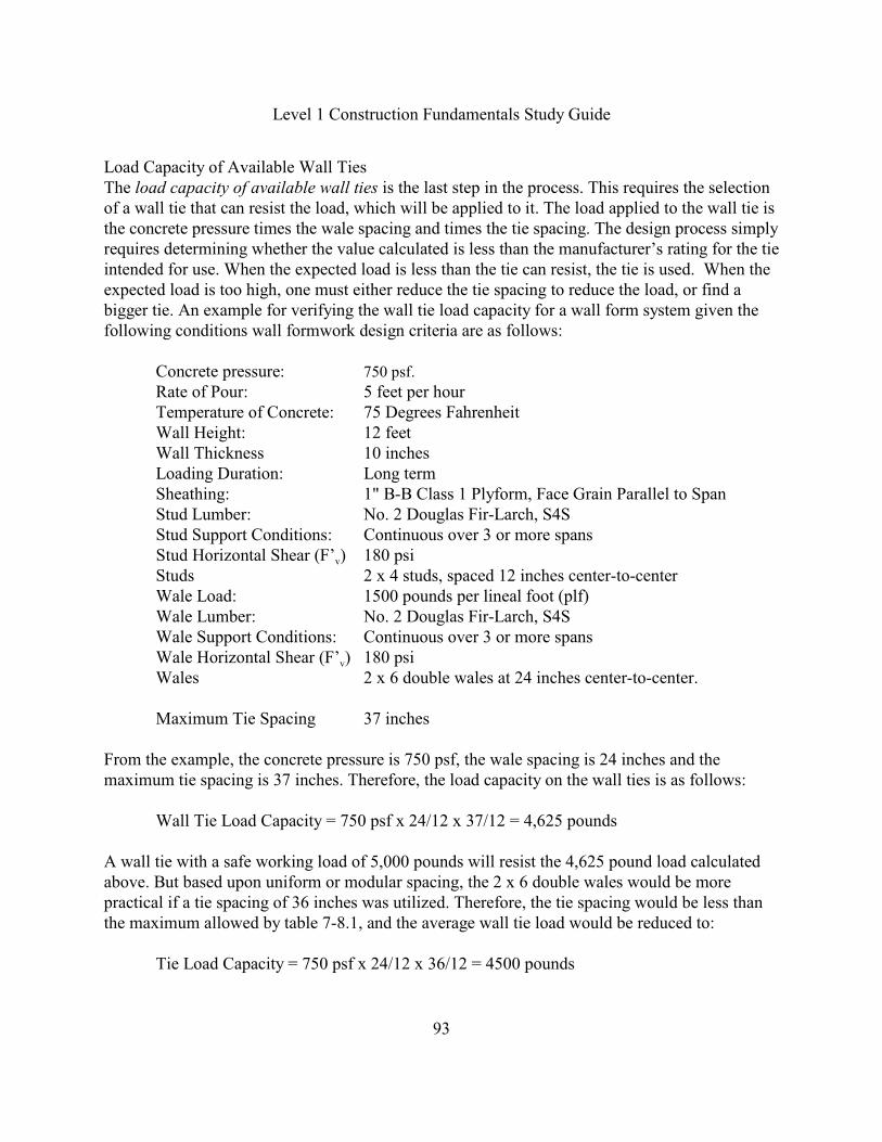
Level 1 Construction Fundamentals Study Guide
93
Load Capacity of Available Wall TiesThe load capacity of available wall ties is the last step in the process. This requires the selectionof a wall tie that can resist the load, which will be applied to it. The load applied to the wall tie isthe concrete pressure times the wale spacing and times the tie spacing. The design process simplyrequires determining whether the value calculated is less than the manufacturer’s rating for the tieintended for use. When the expected load is less than the tie can resist, the tie is used. When theexpected load is too high, one must either reduce the tie spacing to reduce the load, or find abigger tie. An example for verifying the wall tie load capacity for a wall form system given thefollowing conditions wall formwork design criteria are as follows:
Concrete pressure: 750 psf.
Rate of Pour: 5 feet per hourTemperature of Concrete: 75 Degrees FahrenheitWall Height: 12 feetWall Thickness 10 inchesLoading Duration: Long termSheathing: 1" B-B Class 1 Plyform, Face Grain Parallel to SpanStud Lumber: No. 2 Douglas Fir-Larch, S4SStud Support Conditions: Continuous over 3 or more spans
vStud Horizontal Shear (F’ ) 180 psiStuds 2 x 4 studs, spaced 12 inches center-to-centerWale Load: 1500 pounds per lineal foot (plf)Wale Lumber: No. 2 Douglas Fir-Larch, S4SWale Support Conditions: Continuous over 3 or more spans
vWale Horizontal Shear (F’ ) 180 psiWales 2 x 6 double wales at 24 inches center-to-center.
Maximum Tie Spacing 37 inches
From the example, the concrete pressure is 750 psf, the wale spacing is 24 inches and themaximum tie spacing is 37 inches. Therefore, the load capacity on the wall ties is as follows:
Wall Tie Load Capacity = 750 psf x 24/12 x 37/12 = 4,625 pounds
A wall tie with a safe working load of 5,000 pounds will resist the 4,625 pound load calculatedabove. But based upon uniform or modular spacing, the 2 x 6 double wales would be morepractical if a tie spacing of 36 inches was utilized. Therefore, the tie spacing would be less thanthe maximum allowed by table 7-8.1, and the average wall tie load would be reduced to:
Tie Load Capacity = 750 psf x 24/12 x 36/12 = 4500 pounds
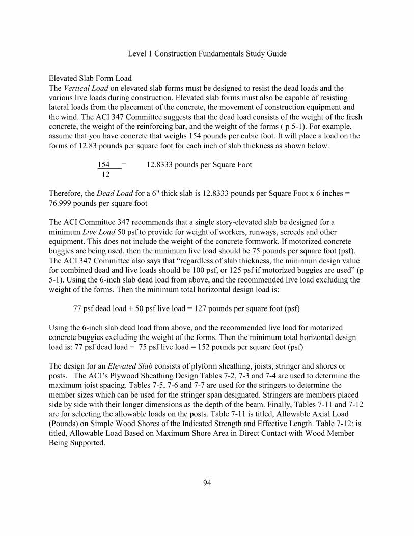
Level 1 Construction Fundamentals Study Guide
94
Elevated Slab Form LoadThe Vertical Load on elevated slab forms must be designed to resist the dead loads and thevarious live loads during construction. Elevated slab forms must also be capable of resistinglateral loads from the placement of the concrete, the movement of construction equipment andthe wind. The ACI 347 Committee suggests that the dead load consists of the weight of the freshconcrete, the weight of the reinforcing bar, and the weight of the forms ( p 5-1). For example,assume that you have concrete that weighs 154 pounds per cubic foot. It will place a load on theforms of 12.83 pounds per square foot for each inch of slab thickness as shown below.
154 = 12.8333 pounds per Square Foot 12
Therefore, the Dead Load for a 6" thick slab is 12.8333 pounds per Square Foot x 6 inches =76.999 pounds per square foot
The ACI Committee 347 recommends that a single story-elevated slab be designed for aminimum Live Load 50 psf to provide for weight of workers, runways, screeds and otherequipment. This does not include the weight of the concrete formwork. If motorized concretebuggies are being used, then the minimum live load should be 75 pounds per square foot (psf).The ACI 347 Committee also says that “regardless of slab thickness, the minimum design valuefor combined dead and live loads should be 100 psf, or 125 psf if motorized buggies are used” (p5-1). Using the 6-inch slab dead load from above, and the recommended live load excluding theweight of the forms. Then the minimum total horizontal design load is:
77 psf dead load + 50 psf live load = 127 pounds per square foot (psf)
Using the 6-inch slab dead load from above, and the recommended live load for motorizedconcrete buggies excluding the weight of the forms. Then the minimum total horizontal designload is: 77 psf dead load + 75 psf live load = 152 pounds per square foot (psf)
The design for an Elevated Slab consists of plyform sheathing, joists, stringer and shores orposts. The ACI’s Plywood Sheathing Design Tables 7-2, 7-3 and 7-4 are used to determine themaximum joist spacing. Tables 7-5, 7-6 and 7-7 are used for the stringers to determine themember sizes which can be used for the stringer span designated. Stringers are members placedside by side with their longer dimensions as the depth of the beam. Finally, Tables 7-11 and 7-12are for selecting the allowable loads on the posts. Table 7-11 is titled, Allowable Axial Load(Pounds) on Simple Wood Shores of the Indicated Strength and Effective Length. Table 7-12: istitled, Allowable Load Based on Maximum Shore Area in Direct Contact with Wood MemberBeing Supported.
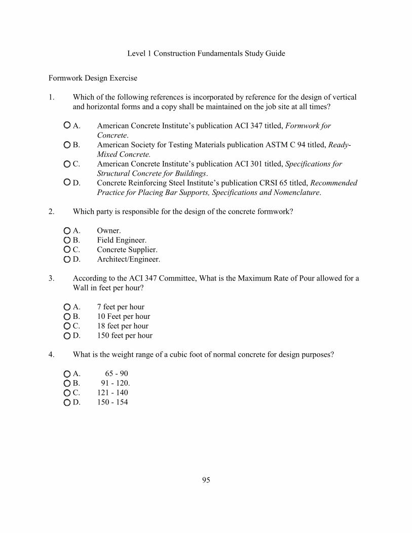
Level 1 Construction Fundamentals Study Guide
95
Formwork Design Exercise
1. Which of the following references is incorporated by reference for the design of verticaland horizontal forms and a copy shall be maintained on the job site at all times?
A. American Concrete Institute’s publication ACI 347 titled, Formwork forConcrete.
B. American Society for Testing Materials publication ASTM C 94 titled, Ready-Mixed Concrete.
C. American Concrete Institute’s publication ACI 301 titled, Specifications forStructural Concrete for Buildings.
D. Concrete Reinforcing Steel Institute’s publication CRSI 65 titled, RecommendedPractice for Placing Bar Supports, Specifications and Nomenclature.
2. Which party is responsible for the design of the concrete formwork?
A. Owner.B. Field Engineer.C. Concrete Supplier.D. Architect/Engineer.
3. According to the ACI 347 Committee, What is the Maximum Rate of Pour allowed for aWall in feet per hour?
A. 7 feet per hourB. 10 Feet per hourC. 18 feet per hourD. 150 feet per hour
4. What is the weight range of a cubic foot of normal concrete for design purposes?
A. 65 - 90 B. 91 - 120.C. 121 - 140D. 150 - 154
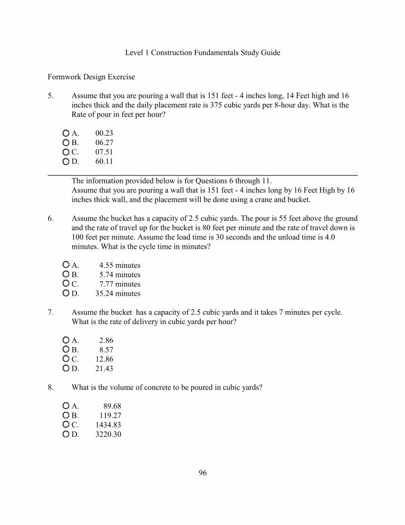
Level 1 Construction Fundamentals Study Guide
96
Formwork Design Exercise
5. Assume that you are pouring a wall that is 151 feet - 4 inches long, 14 Feet high and 16inches thick and the daily placement rate is 375 cubic yards per 8-hour day. What is theRate of pour in feet per hour?
A. 00.23B. 06.27C. 07.51D. 60.11
The information provided below is for Questions 6 through 11. Assume that you are pouring a wall that is 151 feet - 4 inches long by 16 Feet High by 16
inches thick wall, and the placement will be done using a crane and bucket.
6. Assume the bucket has a capacity of 2.5 cubic yards. The pour is 55 feet above the groundand the rate of travel up for the bucket is 80 feet per minute and the rate of travel down is100 feet per minute. Assume the load time is 30 seconds and the unload time is 4.0minutes. What is the cycle time in minutes?
A. 4.55 minutesB. 5.74 minutesC. 7.77 minutesD. 35.24 minutes
7. Assume the bucket has a capacity of 2.5 cubic yards and it takes 7 minutes per cycle.What is the rate of delivery in cubic yards per hour?
A. 2.86B. 8.57C. 12.86D. 21.43
8. What is the volume of concrete to be poured in cubic yards?
A. 89.68B. 119.27C. 1434.83D. 3220.30

Level 1 Construction Fundamentals Study Guide
97
Formwork Design Exercise
9. Assume that you can place 33 Cubic Yards per hour. How many hours are required topour the cubic yards of concrete?
A. 0.28B. 3.61C. 14.91D. 2385.40
10. Assume that it takes 2.25 hours to pour the 151 feet - 4 inches long by 16 Feet High by 16inches thick wall. What is the rate of pour in feet(vertical) per hour?
A. 0.14B. 7.11C. 10.00D. 14.91
11. Assume the pour is using a concrete pump with a capacity of 635 cubic feet per hour.How many hours are required to pour the cubic yards of concrete?
A. 0.03B. 5.07C. 10.00D. 39.69
12. Given the following design conditions for a wall form system:
Wall height = 10 Feet highRate of Pour (R) = 6 Feet per hourConcrete Temperature (T) = 70 Degrees FahrenheitWall Thickness = 15 inches
What is the maximum pressure on the wall in pounds per square foot (psf)?
A. 771B. 921C. 1010D. 1436
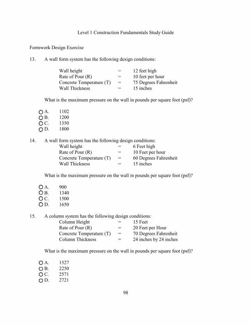
Level 1 Construction Fundamentals Study Guide
98
Formwork Design Exercise
13. A wall form system has the following design conditions:
Wall height = 12 feet highRate of Pour (R) = 10 feet per hourConcrete Temperature (T) = 75 Degrees FahrenheitWall Thickness = 15 inches
What is the maximum pressure on the wall in pounds per square foot (psf)?
A. 1102B. 1200C. 1350D. 1800
14. A wall form system has the following design conditions:Wall height = 6 Feet highRate of Pour (R) = 10 Feet per hourConcrete Temperature (T) = 60 Degrees FahrenheitWall Thickness = 15 inches
What is the maximum pressure on the wall in pounds per square foot (psf)?
A. 900B. 1340C. 1500D. 1650
15. A column system has the following design conditions:Column Height = 15 FeetRate of Pour (R) = 20 Feet per HourConcrete Temperature (T) = 70 Degrees FahrenheitColumn Thickness = 24 inches by 24 inches
What is the maximum pressure on the wall in pounds per square foot (psf)?
A. 1527B. 2250C. 2571D. 2721
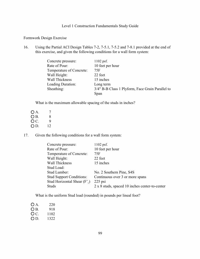
Level 1 Construction Fundamentals Study Guide
99
Formwork Design Exercise
16. Using the Partial ACI Design Tables 7-2, 7-5.1, 7-5.2 and 7-8.1 provided at the end ofthis exercise, and given the following conditions for a wall form system:
Concrete pressure: 1102 psf.
Rate of Pour: 10 feet per hourTemperature of Concrete: 75FWall Height: 22 feetWall Thickness 15 inchesLoading Duration: Long termSheathing: 3/4" B-B Class 1 Plyform, Face Grain Parallel to
Span
What is the maximum allowable spacing of the studs in inches?
A. 7B. 8C. 9D. 12
17. Given the following conditions for a wall form system:
Concrete pressure: 1102 psf.
Rate of Pour: 10 feet per hourTemperature of Concrete: 75FWall Height: 22 feetWall Thickness 15 inchesStud Load:Stud Lumber: No. 2 Southern Pine, S4SStud Support Conditions: Continuous over 3 or more spans
vStud Horizontal Shear (F’ ) 225 psiStuds 2 x 8 studs, spaced 10 inches center-to-center
What is the uniform Stud load (rounded) in pounds per lineal foot?
A. 220B. 918C. 1102D. 1322
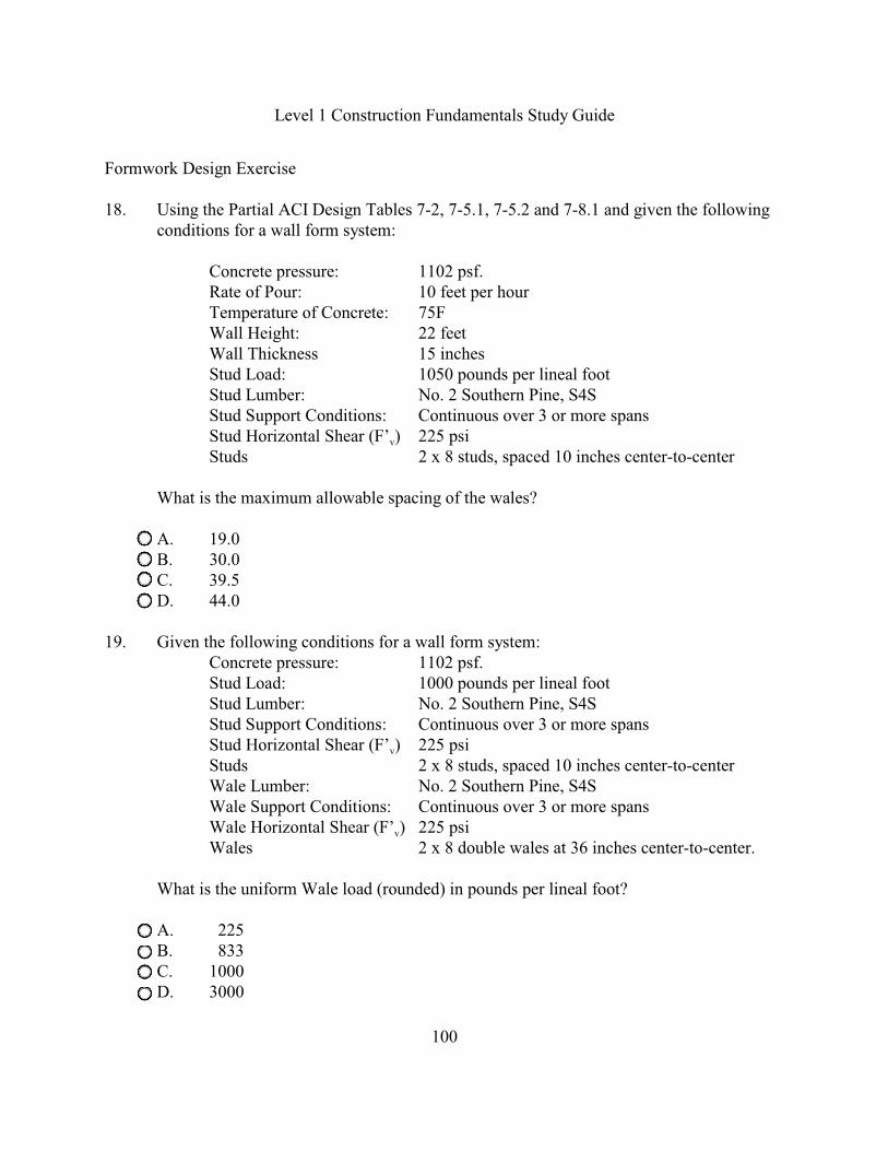
Level 1 Construction Fundamentals Study Guide
100
Formwork Design Exercise
18. Using the Partial ACI Design Tables 7-2, 7-5.1, 7-5.2 and 7-8.1 and given the followingconditions for a wall form system:
Concrete pressure: 1102 psf.Rate of Pour: 10 feet per hourTemperature of Concrete: 75FWall Height: 22 feetWall Thickness 15 inchesStud Load: 1050 pounds per lineal footStud Lumber: No. 2 Southern Pine, S4SStud Support Conditions: Continuous over 3 or more spans
vStud Horizontal Shear (F’ ) 225 psiStuds 2 x 8 studs, spaced 10 inches center-to-center
What is the maximum allowable spacing of the wales?
A. 19.0B. 30.0C. 39.5D. 44.0
19. Given the following conditions for a wall form system:Concrete pressure: 1102 psf.Stud Load: 1000 pounds per lineal footStud Lumber: No. 2 Southern Pine, S4SStud Support Conditions: Continuous over 3 or more spans
vStud Horizontal Shear (F’ ) 225 psiStuds 2 x 8 studs, spaced 10 inches center-to-centerWale Lumber: No. 2 Southern Pine, S4SWale Support Conditions: Continuous over 3 or more spans
vWale Horizontal Shear (F’ ) 225 psiWales 2 x 8 double wales at 36 inches center-to-center.
What is the uniform Wale load (rounded) in pounds per lineal foot?
A. 225B. 833C. 1000D. 3000

Level 1 Construction Fundamentals Study Guide
101
Formwork Design Exercise
20. Using the Partial ACI Design Tables 7-2, 7-5.1, 7-5.2 and 7-8.1 and given the followingconditions for a wall form system:
Wale load 1550 pounds per lineal footWale Lumber: No. 2 Southern Pine, S4SWale Support Conditions: Continuous over 3 or more spans
vWale Horizontal Shear (F’ ) 225 psiWales 2 x 8 double wales at 36 inches center-to-center.
What is the maximum allowable tie spacing in inches?
A. 36.5 B. 40.5C. 46.0D. 51.5
21. Given the following conditions for a wall form system:
Concrete pressure: 1102 psf.Stud Load: 1000 pounds per lineal footStud Lumber: No. 2 Southern Pine, S4SStud Support Conditions: Continuous over 3 or more spans
vStud Horizontal Shear (F’ ) 225 psiStuds 2 x 8 studs, spaced 10 inches center-to-centerWale Load: 2000 pounds per lineal foot (plf)Wale Lumber: No. 2 Southern Pine, S4SWale Support Conditions: Continuous over 3 or more spans
vWale Horizontal Shear (F’ ) 225 psiWales 2 x 8 double wales at 36 inches center-to-center.
Maximum Tie Spacing: 45 inches
What is the Wall Tie load capacity in pounds (rounded to whole number)?
A. 2000B. 2755C. 2918D. 12398
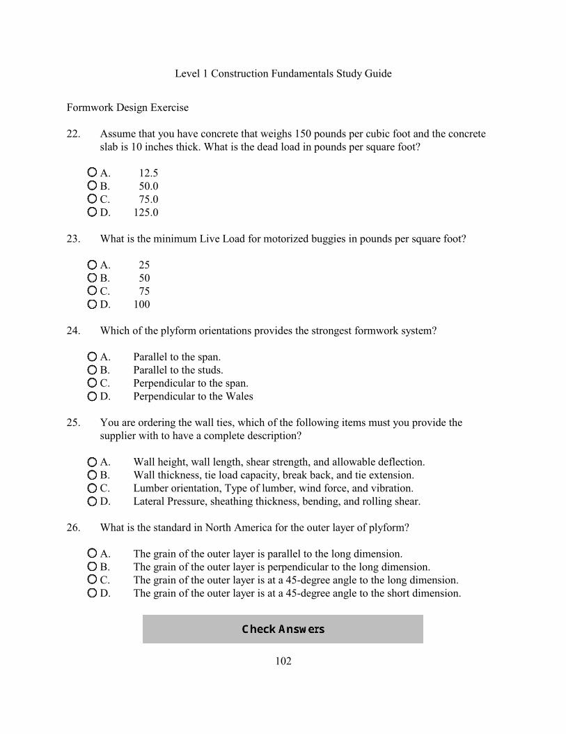
Level 1 Construction Fundamentals Study Guide
102
Formwork Design Exercise
22. Assume that you have concrete that weighs 150 pounds per cubic foot and the concreteslab is 10 inches thick. What is the dead load in pounds per square foot?
A. 12.5B. 50.0C. 75.0D. 125.0
23. What is the minimum Live Load for motorized buggies in pounds per square foot?
A. 25B. 50C. 75D. 100
24. Which of the plyform orientations provides the strongest formwork system?
A. Parallel to the span.B. Parallel to the studs.C. Perpendicular to the span.D. Perpendicular to the Wales
25. You are ordering the wall ties, which of the following items must you provide thesupplier with to have a complete description?
A. Wall height, wall length, shear strength, and allowable deflection.B. Wall thickness, tie load capacity, break back, and tie extension.C. Lumber orientation, Type of lumber, wind force, and vibration.D. Lateral Pressure, sheathing thickness, bending, and rolling shear.
26. What is the standard in North America for the outer layer of plyform?
A. The grain of the outer layer is parallel to the long dimension.B. The grain of the outer layer is perpendicular to the long dimension.C. The grain of the outer layer is at a 45-degree angle to the long dimension.D. The grain of the outer layer is at a 45-degree angle to the short dimension.
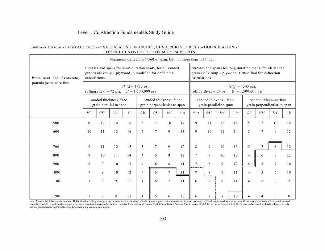
Level 1 Construction Fundamentals Study Guide
103
Formwork Exercise - Partial ACI Table 7-2: SAFE SPACING, IN INCHES, OF SUPPORTS FOR PLYWOOD SHEATHING,
CONTINUOUS OVER FOUR OR MORE SUPPORTS
Maximum deflection 1/360 of span, but not more than 1/16 inch.
Pressure or load of concrete,
pounds per square foot
Stresses and spans for short duration loads, for all sanded
grades of Group 1 plywood, E modified for deflection
calculations
Stresses and spans for long duration loads, for all sanded
grades of Group 1 plywood, E modified for deflection
calculations
b(F’ ) = 1930 psi.
rolling shear = 72 psi; E’ = 1,500,000 psib(F’ ) = 1545 psi.
rolling shear = 57 psi; E’ = 1,500,000 psi
sanded thickness, face
grain parallel to span
sanded thickness, face
grain perpendicular to span
sanded thickness, face
grain parallel to span
sanded thickness, face
grain perpendicular to span
½” 5/8" 3/4" 1" ½ in 5/8" 3/4" 1 in ½ in 5/8" 3/4" 1 in ½ “ 5/8" 3/4" 1 in
500 10 12 14 18 5 7 10 14 9 11 12 16 5 7 10 14
600 10 11 13 16 5 7 9 13 9 10 11 14 5 7 9 13
700 9 11 12 15 5 7 9 12 8 9 10 13 5 7 8 12
800 9 10 11 14 4 6 8 12 7 9 10 12 4 6 7 12
900 8 9 10 13 4 6 8 11 7 8 9 12 4 5 7 10
1000 7 9 10 12 4 6 7 11 7 8 9 11 4 5 6 10
1100 7 8 9 12 4 6 7 11 6 8 8 11 4 5 6 9
1200 7 8 9 11 4 5 6 10 6 7 8 10 4 4 5 8Note: Above solid, deflection controls span. Below dash line, rolling shear governs. Between the lines, bending controls. Spans are given center to center of supports., assuming 1-1/2 inch support width for shear spans. If supports of a different with are used, detailedcalculations should be made to check spans in the range now shown as controlled by shear. Adapted from American Concrete Institute’s publication Formwork for Concrete. Sixth Edition, Design Table 7-2 (p 7-7). This is a partial table for educational purposes onlyand you must reference ACI’s publications for complete and accurate information.
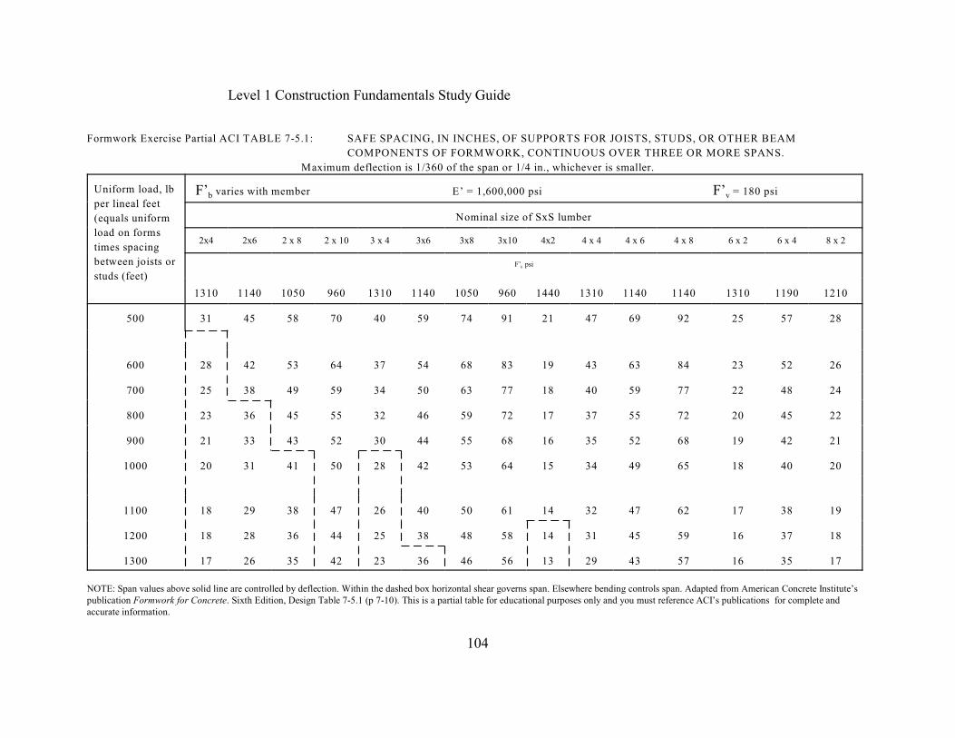
Level 1 Construction Fundamentals Study Guide
104
Formwork Exercise Partial ACI TABLE 7-5.1: SAFE SPACING, IN INCHES, OF SUPPORTS FOR JOISTS, STUDS, OR OTHER BEAM
COMPONENTS OF FORMWORK, CONTINUOUS OVER THREE OR MORE SPANS.
Maximum deflection is 1/360 of the span or 1/4 in., whichever is smaller.
Uniform load, lb
per lineal feet
(equals uniform
load on forms
times spacing
between joists or
studs (feet)
b v F’ varies with member E’ = 1,600,000 psi F’ = 180 psi
Nominal size of SxS lumber
2x4 2x6 2 x 8 2 x 10 3 x 4 3x6 3x8 3x10 4x2 4 x 4 4 x 6 4 x 8 6 x 2 6 x 4 8 x 2
bF’ psi
1310 1140 1050 960 1310 1140 1050 960 1440 1310 1140 1140 1310 1190 1210
500 31 45 58 70 40 59 74 91 21 47 69 92 25 57 28
600 28 42 53 64 37 54 68 83 19 43 63 84 23 52 26
700 25 38 49 59 34 50 63 77 18 40 59 77 22 48 24
800 23 36 45 55 32 46 59 72 17 37 55 72 20 45 22
900 21 33 43 52 30 44 55 68 16 35 52 68 19 42 21
1000 20 31 41 50 28 42 53 64 15 34 49 65 18 40 20
1100 18 29 38 47 26 40 50 61 14 32 47 62 17 38 19
1200 18 28 36 44 25 38 48 58 14 31 45 59 16 37 18
1300 17 26 35 42 23 36 46 56 13 29 43 57 16 35 17
NOTE: Span values above solid line are controlled by deflection. Within the dashed box horizontal shear governs span. Elsewhere bending controls span. Adapted from American Concrete Institute’spublication Formwork for Concrete. Sixth Edition, Design Table 7-5.1 (p 7-10). This is a partial table for educational purposes only and you must reference ACI’s publications for complete andaccurate information.
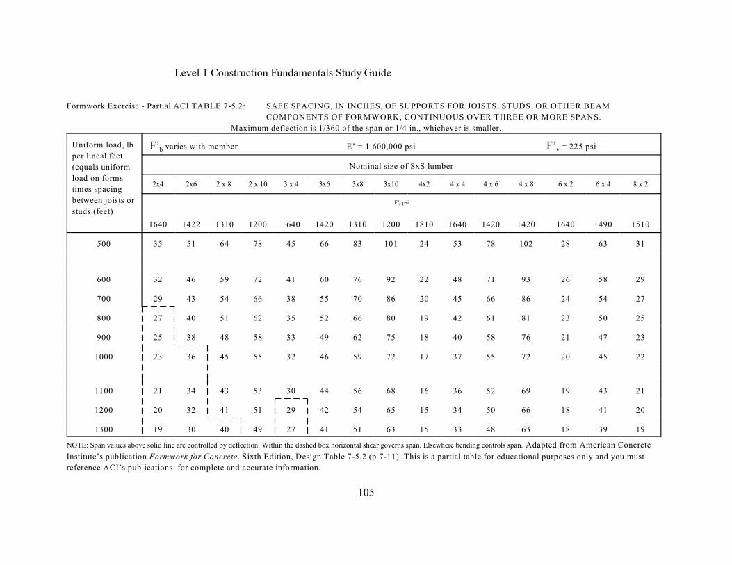
Level 1 Construction Fundamentals Study Guide
105
Formwork Exercise - Partial ACI TABLE 7-5.2: SAFE SPACING, IN INCHES, OF SUPPORTS FOR JOISTS, STUDS, OR OTHER BEAM
COMPONENTS OF FORMWORK, CONTINUOUS OVER THREE OR MORE SPANS.
Maximum deflection is 1/360 of the span or 1/4 in., whichever is smaller.
Uniform load, lb
per lineal feet
(equals uniform
load on forms
times spacing
between joists or
studs (feet)
b v F’ varies with member E’ = 1,600,000 psi F’ = 225 psi
Nominal size of SxS lumber
2x4 2x6 2 x 8 2 x 10 3 x 4 3x6 3x8 3x10 4x2 4 x 4 4 x 6 4 x 8 6 x 2 6 x 4 8 x 2
bF’ psi
1640 1422 1310 1200 1640 1420 1310 1200 1810 1640 1420 1420 1640 1490 1510
500 35 51 64 78 45 66 83 101 24 53 78 102 28 63 31
600 32 46 59 72 41 60 76 92 22 48 71 93 26 58 29
700 29 43 54 66 38 55 70 86 20 45 66 86 24 54 27
800 27 40 51 62 35 52 66 80 19 42 61 81 23 50 25
900 25 38 48 58 33 49 62 75 18 40 58 76 21 47 23
1000 23 36 45 55 32 46 59 72 17 37 55 72 20 45 22
1100 21 34 43 53 30 44 56 68 16 36 52 69 19 43 21
1200 20 32 41 51 29 42 54 65 15 34 50 66 18 41 20
1300 19 30 40 49 27 41 51 63 15 33 48 63 18 39 19
NOTE: Span values above solid line are controlled by deflection. Within the dashed box horizontal shear governs span. Elsewhere bending controls span. Adapted from American Concrete
Institute’s publication Formwork for Concrete. Sixth Edition, Design Table 7-5.2 (p 7-11). This is a partial table for educational purposes only and you must
reference ACI’s publications for complete and accurate information.
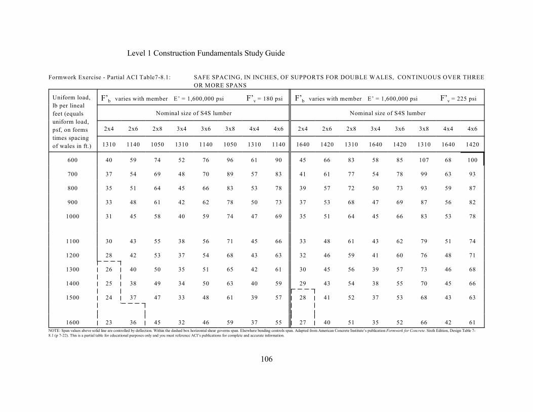
Level 1 Construction Fundamentals Study Guide
106
Formwork Exercise - Partial ACI Table7-8.1: SAFE SPACING, IN INCHES, OF SUPPORTS FOR DOUBLE WALES, CONTINUOUS OVER THREE
OR MORE SPANS
Uniform load,
lb per lineal
feet (equals
uniform load,
psf, on forms
times spacing
of wales in ft.)
b v b vF’ varies with member E’ = 1,600,000 psi F’ = 180 psi F’ varies with member E’ = 1,600,000 psi F’ = 225 psi
Nominal size of S4S lumber Nominal size of S4S lumber
2x4 2x6 2x8 3x4 3x6 3x8 4x4 4x6 2x4 2x6 2x8 3x4 3x6 3x8 4x4 4x6
1310 1140 1050 1310 1140 1050 1310 1140 1640 1420 1310 1640 1420 1310 1640 1420
600 40 59 74 52 76 96 61 90 45 66 83 58 85 107 68 100
700 37 54 69 48 70 89 57 83 41 61 77 54 78 99 63 93
800 35 51 64 45 66 83 53 78 39 57 72 50 73 93 59 87
900 33 48 61 42 62 78 50 73 37 53 68 47 69 87 56 82
1000 31 45 58 40 59 74 47 69 35 51 64 45 66 83 53 78
1100 30 43 55 38 56 71 45 66 33 48 61 43 62 79 51 74
1200 28 42 53 37 54 68 43 63 32 46 59 41 60 76 48 71
1300 26 40 50 35 51 65 42 61 30 45 56 39 57 73 46 68
1400 25 38 49 34 50 63 40 59 29 43 54 38 55 70 45 66
1500 24 37 47 33 48 61 39 57 28 41 52 37 53 68 43 63
1600 23 36 45 32 46 59 37 55 27 40 51 35 52 66 42 61NOTE: Span values above solid line are controlled by deflection. Within the dashed box horizontal shear governs span. Elsewhere bending controls span. Adapted from American Concrete Institute’s publication Formwork for Concrete. Sixth Edition, Design Table 7-8.1 (p 7-22). This is a partial table for educational purposes only and you must reference ACI’s publications for complete and accurate information.
Level 1 Construction Fundamentals Study Guide
107
Soil Mechanics
Soil Investigation TestsSoil Investigation or Soil Exploration consists of three steps: boring, sampling and testing. First,the boring refers to the drilling of a hole in the ground. Some of the most common types ofborings are auger borings, wash borings, test pits, and core borings. Second, sampling refers tothe removing the soil from the holes. Samples may be classified as either disturbed orundisturbed. Auger borings and wash boring methods bring the soil sample to the surface wheresamples are collected. Soil samples by these methods are considered disturbed samples ans someof their characteristics are changed. Soil sampling is the equipment used to extract, contain andseal the samples from the borings during the subsurface soil investigation. At the surface, thedisturbed soil samples should be placed in airtight containers and labeled for the lab. Third,testing refers to the lab and field tests that can be conducted to determine the soil properties.
There are numerous tests that can be made to evaluate various soil properties, but the mostcommon test in the United States is the Standard Penetration Test (SPT). The StandardPenetration Test (SPT) is useful in determining certain properties of cohesionless soils. The SPTutilizes a split spoon sampler which has an outside diameter (O.D.) of 2 inches and it is 18 - 24inches long. The sampler is attached to the bottom of a drilling rod and driven into the soil with a140 pound hammer falling 30 inches. As the sampler is driven the 18 inches into the sampler, thenumber of blows required to penetrate each of the three 6 inch increments is recorded separatelyon the boring log. The standard penetration resistance “N” value is the number of blows requiredto penetrate the last 12 inches. Below is an example of a partial Geotechnical or SoilInvestigation Report and on the following pages is an example of the Soil Boring Location Plan,the Soil Boring #8 and the Relative Density and Consistency Table. These are the ProposedPublic Service Building Procedures:
The borings were drilled using a CME model 45 “skid” drill rig. The drill rig utilized hollowstem augers to sample depths where samples were obtained in a two-inch O.D. split spoonsampler driven by a 140 pound hammer falling 30 inches. The number of blows required to drivethe sampler three six-inch increments are recorded on the boring logs. The first six inches isconsidered the seating drive. The summation of the number of blows required for the second andthird six inches is termed the penetration resistance “N” value in blows per foot (bpf). This fieldprocedure is referred to as the Standard Penetration Test (SPT) and is an American Society forTesting and Materials test procedure (ASTM D-1586).
The “N” values from the SPT are used for the determination of the relative density of granularsoils (sand, gravel, low plasticity silt, and mixtures of sand and gravel) or the consistency ofcohesive soils (clay and plastic silts). A chart is provided in the back of this report whichprovides a correlation between “N” values and the relative density of granular soils or theconsistency of cohesive soils.

Level 1 Construction Fundamentals Study Guide
108
Proposed Public Service Building Soil Boring Location Plan
Soil Investigation ReportThe Soil Investigation Report is used to identify the drilling procedures and the penetrationresistance “N” value. From each Soil Boring, you can extract the water table, the PenetrationBlow Counts and the Soil Classification provided by the testing firm. Finally, it is theContractor’s responsibility to determine the Penetration “N” value from the Soil Boring, which isthe summation of the number of blows required for the second and third penetration counts. Thenusing this total number of blows, you must determine the relative density of sand or theconsistency of clay and compare the table’s description to the to the Soil ClassificationDescription on the soil boring.

Level 1 Construction Fundamentals Study Guide
109
Proposed Public Service Building Soil Boring Example
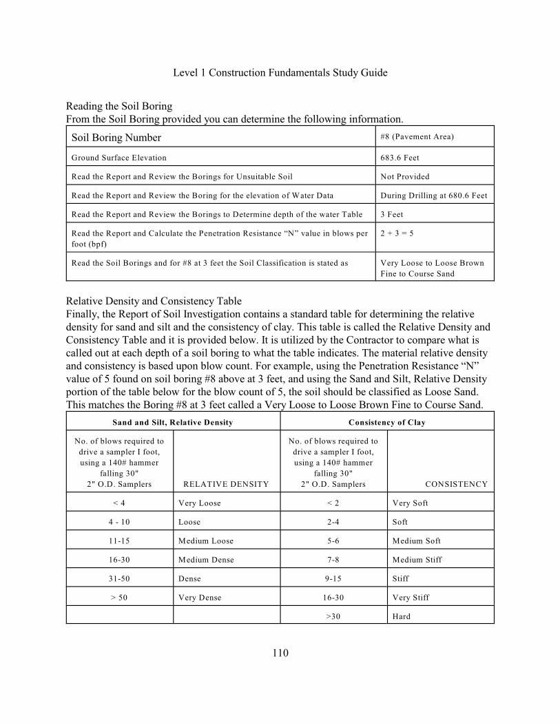
Level 1 Construction Fundamentals Study Guide
110
Reading the Soil BoringFrom the Soil Boring provided you can determine the following information.
Soil Boring Number #8 (Pavement Area)
Ground Surface Elevation 683.6 Feet
Read the Report and Review the Borings for Unsuitable Soil Not Provided
Read the Report and Review the Boring for the elevation of Water Data During Drilling at 680.6 Feet
Read the Report and Review the Borings to Determine depth of the water Table 3 Feet
Read the Report and Calculate the Penetration Resistance “N” value in blows per
foot (bpf)
2 + 3 = 5
Read the Soil Borings and for #8 at 3 feet the Soil Classification is stated as Very Loose to Loose Brown
Fine to Course Sand
Relative Density and Consistency TableFinally, the Report of Soil Investigation contains a standard table for determining the relativedensity for sand and silt and the consistency of clay. This table is called the Relative Density andConsistency Table and it is provided below. It is utilized by the Contractor to compare what iscalled out at each depth of a soil boring to what the table indicates. The material relative densityand consistency is based upon blow count. For example, using the Penetration Resistance “N”value of 5 found on soil boring #8 above at 3 feet, and using the Sand and Silt, Relative Densityportion of the table below for the blow count of 5, the soil should be classified as Loose Sand.This matches the Boring #8 at 3 feet called a Very Loose to Loose Brown Fine to Course Sand.
Sand and Silt, Relative Density Consistency of Clay
No. of blows required to
drive a sampler I foot,
using a 140# hammer
falling 30"
2" O.D. Samplers RELATIVE DENSITY
No. of blows required to
drive a sampler I foot,
using a 140# hammer
falling 30"
2" O.D. Samplers CONSISTENCY
< 4 Very Loose < 2 Very Soft
4 - 10 Loose 2-4 Soft
11-15 Medium Loose 5-6 Medium Soft
16-30 Medium Dense 7-8 Medium Stiff
31-50 Dense 9-15 Stiff
> 50 Very Dense 16-30 Very Stiff
>30 Hard
Level 1 Construction Fundamentals Study Guide
111
Soil CategoriesSoils are separated in three broad categories. They are cohesionless, cohesive and organic soils.Cohensionless soils are gravel, sand, and silt. Gravel has particle sizes of 3 inches down to a #4sieve. Sand particles range from a #4 sieve down to a #200 sieve. Sand and gravel can be furtherdivided into fine and course such as fine sand and course sand. Finally, clay or the fines is a #200sieve on down. The common type of cohesive soil is clay which has particle sizes less than a#200 sieve. Organic soil are undesirable for supporting structures and must not contaminate thedesirable sands and gravels. Finally, Loam roughly contains equal parts of sand, silt and clay.
A cohesive soils particle sizes may be determined by the hydrometer method which is a processfor indirectly observing the settling velocities of the particles in a soil-water mixture. Anothertechnique for analyzing cohesive soils is by use of the Atterberg limits method. Atterberg definefour states of consistency for cohesive soils. They are liquid, plastic, semisolid, and solid.
Soil properties and characteristics are influenced by changes in water content and there are threephenomena that are directly related to the water in the soil. They are permeability, capillarity, andfrost heave. Permeability is the movement of water within a soil. Capillarity is the rise of waterabove the ground water table against the pull of gravity but is in contact with the water table asits source. Frost heave is the vertical expansion of soil caused by water freezing.
Soil Classification SystemsThe most commonly used Soil Classification Systems based upon grain size are the Unified SoilClassification System (USCS). and the American Association of State Highway andTransportation Officials (AASHTO) system. The OSHA Standards for the Construction Industryin 29 CFR PART 1926.650 in Appendix A of Subpart P titled Soil Classification paragraph (c)Requirements (1) Classification and (2) Basis of classification it states that “the classification ofthe soil deposits shall be made based on the results of at least one visual inspection and at leastone manual analysis (p 257). The standard also incorporates by reference the American Societyfor Testing Materials (ASTM) standard D2488 titled, Standard Recommended PracticesDescription of Soils. Therefore, a person must have a basic understanding of soil terminology sothat they can properly identify and classify the soil. Your daily excavation inspections willrequire you to use the following soil terminology. According to OSHA 1926 Appendix Aparagraph (b) Definitions it states that “the definitions and example . . are based on, in whole orin part, the following: American Society for Testing Materials (ASTM) Standards D653-85 andD2488; The Unified Soils Classification System; The U.S. Department of Agriculture (USDA)Textural Classification Scheme; and the National Bureau of Standards Report BSS-121.
A Cemented Soil means a soil in which the particles are held together by a chemical agent, suchas calcium carbonate, such that a hand-size sample cannot be crushed into a powder or individualsoil particles by finger pressure. Cemented soils include hardpan. These soils are also extremelyhard to excavate.

Level 1 Construction Fundamentals Study Guide
112
A Clay is a soil that is hard to break up when dry, but can be crushed to a powder (fine grainedsoil) and can be moldable when wet and sticks together (cohesive). A Cohesive Soil is a soil witha high clay content which sticks together when wet or dry. Cohesive soil does not crumble, canbe excavated with vertical side slopes, and is plastic when moist. Cohesive soil is hard to breakup when dry, and exhibits significant cohesion when submerged under water. Cohesive soilsinclude clayey silt, sandy clay, silty clay, clay and organic clay. A Cohensionless soil is a loosesand or granular gravel that freely runs. A Dry Soil is a soil that does not exhibit visible signs ofmoisture content.
A Granular Soil means a gravel , sand or silt with little or no clay content. Granular soil has nocohesive strength. Some moist granular soils exhibit apparent cohesion. Granular soil cannot bemolded when moist and crumbles easily when dry. A Layered System means two or moredistinctly different soils or rock types arranged in layers. Micaceous seams or weakened planes inrock or shale are considered layered. Moist soil means a soil condition in which a soil looks andfeels damp. Moist cohesive soil can easily be shaped into a ball and rolled into small diameterthreads before crumbling. Moist granular soil that contains some cohesive material will exhibitsigns of cohesion between particles. A Plastic soil means a property of a soil which allows thesoil to be deformed or molded without cracking, or appreciable volume change.
A Saturated Soil is a soil in which the voids are filled with water. Saturation does not requireflow. Saturation or near saturation, is necessary for the proper use of instruments such as a pocketpentrometer or torvane. A Spoil refers to the earth and material drawn from an excavation. Theterm Submerged Soil means soil which is under water or is free seeping. Wet soil means soil thatcontains significantly more moisture than moist soil, but in such range of values that cohesivematerial will slump or begin to flow when vibrated. Granular material that would exhibitcohesive properties when moist will lose those cohesive properties when wet.
According to the standards, the acceptable Field Soil Visual Tests shall be conducted to providesufficient quantitative and qualitative information as may be necessary to identify properly theproperties, factors, and conditions affecting the classification of the soil. Visual analysis isconducted to determine the qualitative information regarding the excavation site in general, thesoil adjacent to the excavation, the soil forming the sides of the open excavation, and the soiltaken as examples from excavated material. Therefore, it is imperative that while making a visualinspection that you look for distress and the signs of trench failure. It should be understood thatClay is one of the most dangerous materials because the vertical walls of an excavation appear tobe solid and stable. However, clay is drastically effected by water, wind, and pressure. Watercauses it to swell, wind causes it to dry and shrink rapidly, and the soil pressure causes clay tobulge. Any or all of the conditions described above can cause trench failure. Below are thedefinitions of the types of distress that result in trench failure.
Level 1 Construction Fundamentals Study Guide
113
Types of Distress that Result in Trench FailureDistress means that the soil is in a condition where a cave-in is imminent or is likely to occur.Distress is evidenced by such phenomena as the development of fissures in the face of or surfaceof an open excavation; the subsidence of the horizontal plane of an excavation; the bulging of theface of an excavation; the heaving of material from the bottom of an excavation; the spalling ofmaterial from the face of a rock excavation; the raveling of small amounts of material tricklingdown into the excavation; and the seeping of water into the excavation.
The initial signs of trench failure begin immediately after removing the soil, the trench becomesunstable and the soil in the trench walls begins to move into the excavation. This movementusually is not visible but the soil is moving because the surface of the ground is in tension,therefore, the weight of the soil causes surface cracks parallel to the trench, approximately one-third to two-thirds of the trench depth from the trench edge. For example, if the depth of thetrench is 9 feet deep, these surface tension cracks may be found somewhere between three (3)feet and six (6) feet from the edge of the trench. The edge of the excavation may also subside butthis is hard to see.
The second sign of trench failure is in the face of the excavation, Cracks, normally horizontal,may appear on the face and the walls of the excavation may bulge into the excavation but thesesigns of failure are also hard to see. The third sign of progressive trench failure is when thebottom of the trench initially fails or kicks into the excavation. This leaves the upper portion ofthe face unsupported and the trench wall is hanging on by the shear force. A second failure willoccur soon after the first failure as the upper portion of the excavation collapses into the trench.Often a worker is trapped by the initial cave-in and co-workers will jump into the trench to help,unaware that multiple cave-ins are likely. Normally, the second and third cave-ins are the onesthat will kill or injure the rescuers. Therefore, you should be aware that cave-ins normally occurin multiples. The final sign of trench failure is rain flowing into the surface cracks will increasethe surcharge load in the soil. These fissures may appear to close while wet but they will reappearwider after some drying takes place. Water will also be retained in the spoil pile and this willcreate an increase in the surcharge load on the trench.
Field Visual Inspections for ExcavationThere are over fifteen potential Types of Distress That Result in Trench Failure that you mustperiodically visually inspect for when an excavation is open. The following distresses are definedbelow to help you identify the potential types of soil conditions at the job site that may lead to atrench failure. Fissured means a soil material that has a tendency to break along definite planesof fracture with little resistance, or a material that exhibits open cracks, such as tension cracks, inan exposed surface such as on the existing horizontal surface or on the excavation face. Theexcavation face means the vertical or inclined earth surfaces formed as a result of the excavationwork. This is sometimes referred to as the excavation sides.

Level 1 Construction Fundamentals Study Guide
114
Unsupported Faces or Walls are immediately developed once an excavation is excavated and theweight of the soil, due to gravity places vertical and horizontal (lateral) pressure on the wall. This gravity translates directly to weight. In many cases, one cubic foot of soil weights anaverage of 120 pounds per cubic foot. A column of soil one foot wide, five feet deep and sixlong weighing 120 pounds per cubic foot would weigh 3600 pounds per side. (1 foot wide x 5feet deep x 6 feet long x 120 pounds per cubic foot). If you multiply each vertical wall by two, afull cave-in could easily be 7200 pounds.
Other visual inspections are for Bulging which occurs as a result of the vertical and lateral forcesbeing exerted on the unsupported walls. Bulging will first appear on the face of the wall asprotrusions into the open excavation. Subsidence occurs as a result of unbalanced stresses in thesoil. Subsidence causes the soil to sink on the surface and bulging of the vertical face of thetrench. If uncorrected, this condition can cause face failure and entrapment of workers in thetrench. Heaving or squeezing is caused by the downward pressure created by the weight ofadjoining soil. This pressure causes a bulge in the bottom of the cut. Heaving and squeezing canoccur even when shoring or shielding has been properly installed. Boiling is evidenced by anupward water flow into the bottom of the cut. A high water table is one of the causes of boiling.Boiling produces a "quick" condition in the bottom of the cut, and can occur even when shoringor trench boxes are used. Some additional visual inspections are for Raveling which is evidencedby small amounts of material suddenly separating from the face of an excavation and trickling orrolling down into the excavation. Spalling is evidenced by small fragments of rock break up orscale off the excavation face. This is caused by vibration near a fractured unstable rock face.
Other visual inspections are for a Surcharge Load means an excessive vertical load or weightcaused by the spoil pile being too close to the trench edge or equipment being too close to thetrench edge. These activities effect the trench stability. Vibration is a dynamic force introducedinto the ground from blasting, pile driving, traffic, construction equipment and proximity torailroad tracks and industrial turbines. Undercutting is caused by excavating below the existingfoundation of a nearby structures and not providing enough clearance area. A PreviouslyDisturbed Soil is a soil which will never return to its original position or stability. Thepreviously disturbed soil will slide or ravel into the new excavation. Finally, you must inspect fora Layered Soil System where two or more distinctly different soils or rock types are arranged inlayers. The soil layers slope into the excavation at a four Horizontal to one Vertical (4H:IV) orsteeper slope. A layered system is controlled by its weakest layer and this can result in a wedgefailure.
Some trench failure terms are Sliding or slumping may occur as a result of tension cracks, weaksoil, water soaked soil, hard soil or rock on top of a weak soil layer. Toppling is also caused bytension cracks. Toppling occurs when the trench's vertical face shears along the tension crack lineand topples into the excavation. Sloughing is where the sides cave into the trench duringexcavation.
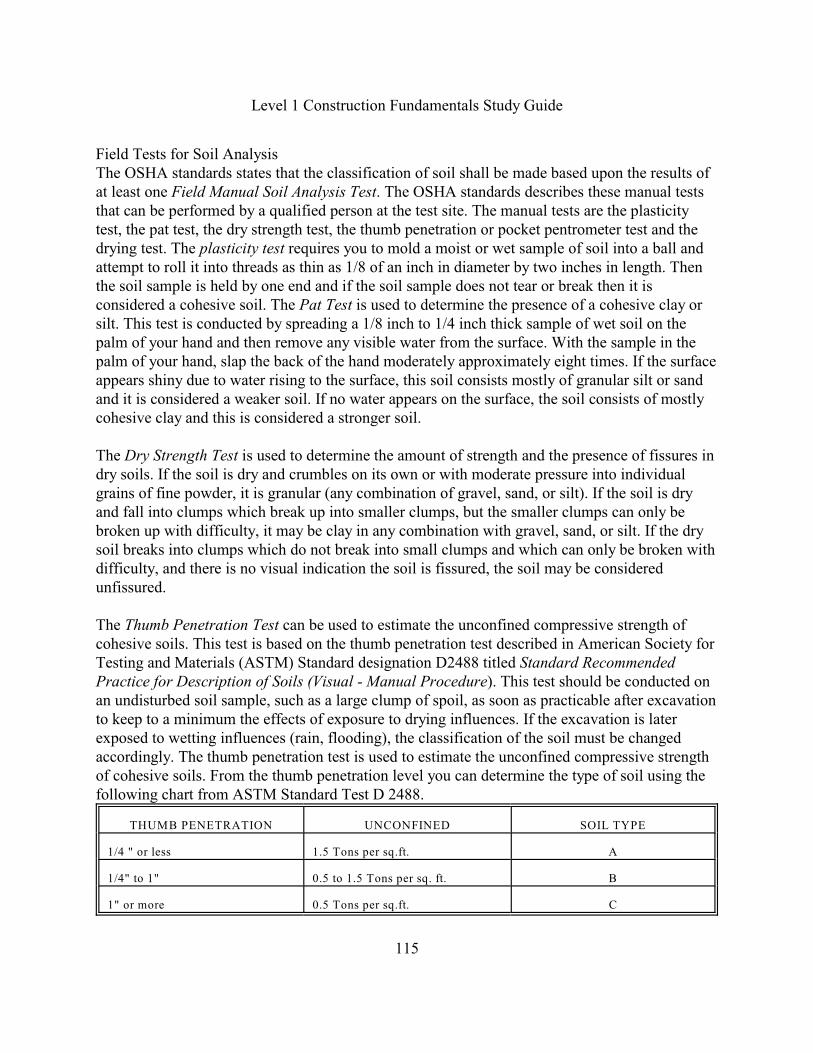
Level 1 Construction Fundamentals Study Guide
115
Field Tests for Soil AnalysisThe OSHA standards states that the classification of soil shall be made based upon the results ofat least one Field Manual Soil Analysis Test. The OSHA standards describes these manual teststhat can be performed by a qualified person at the test site. The manual tests are the plasticitytest, the pat test, the dry strength test, the thumb penetration or pocket pentrometer test and thedrying test. The plasticity test requires you to mold a moist or wet sample of soil into a ball andattempt to roll it into threads as thin as 1/8 of an inch in diameter by two inches in length. Thenthe soil sample is held by one end and if the soil sample does not tear or break then it isconsidered a cohesive soil. The Pat Test is used to determine the presence of a cohesive clay orsilt. This test is conducted by spreading a 1/8 inch to 1/4 inch thick sample of wet soil on thepalm of your hand and then remove any visible water from the surface. With the sample in thepalm of your hand, slap the back of the hand moderately approximately eight times. If the surfaceappears shiny due to water rising to the surface, this soil consists mostly of granular silt or sandand it is considered a weaker soil. If no water appears on the surface, the soil consists of mostlycohesive clay and this is considered a stronger soil.
The Dry Strength Test is used to determine the amount of strength and the presence of fissures indry soils. If the soil is dry and crumbles on its own or with moderate pressure into individualgrains of fine powder, it is granular (any combination of gravel, sand, or silt). If the soil is dryand fall into clumps which break up into smaller clumps, but the smaller clumps can only bebroken up with difficulty, it may be clay in any combination with gravel, sand, or silt. If the drysoil breaks into clumps which do not break into small clumps and which can only be broken withdifficulty, and there is no visual indication the soil is fissured, the soil may be consideredunfissured.
The Thumb Penetration Test can be used to estimate the unconfined compressive strength ofcohesive soils. This test is based on the thumb penetration test described in American Society forTesting and Materials (ASTM) Standard designation D2488 titled Standard RecommendedPractice for Description of Soils (Visual - Manual Procedure). This test should be conducted onan undisturbed soil sample, such as a large clump of spoil, as soon as practicable after excavationto keep to a minimum the effects of exposure to drying influences. If the excavation is laterexposed to wetting influences (rain, flooding), the classification of the soil must be changedaccordingly. The thumb penetration test is used to estimate the unconfined compressive strengthof cohesive soils. From the thumb penetration level you can determine the type of soil using thefollowing chart from ASTM Standard Test D 2488.
THUMB PENETRATION UNCONFINED SOIL TYPE
1/4 " or less 1.5 Tons per sq.ft. A
1/4" to 1" 0.5 to 1.5 Tons per sq. ft. B
1" or more 0.5 Tons per sq.ft. C
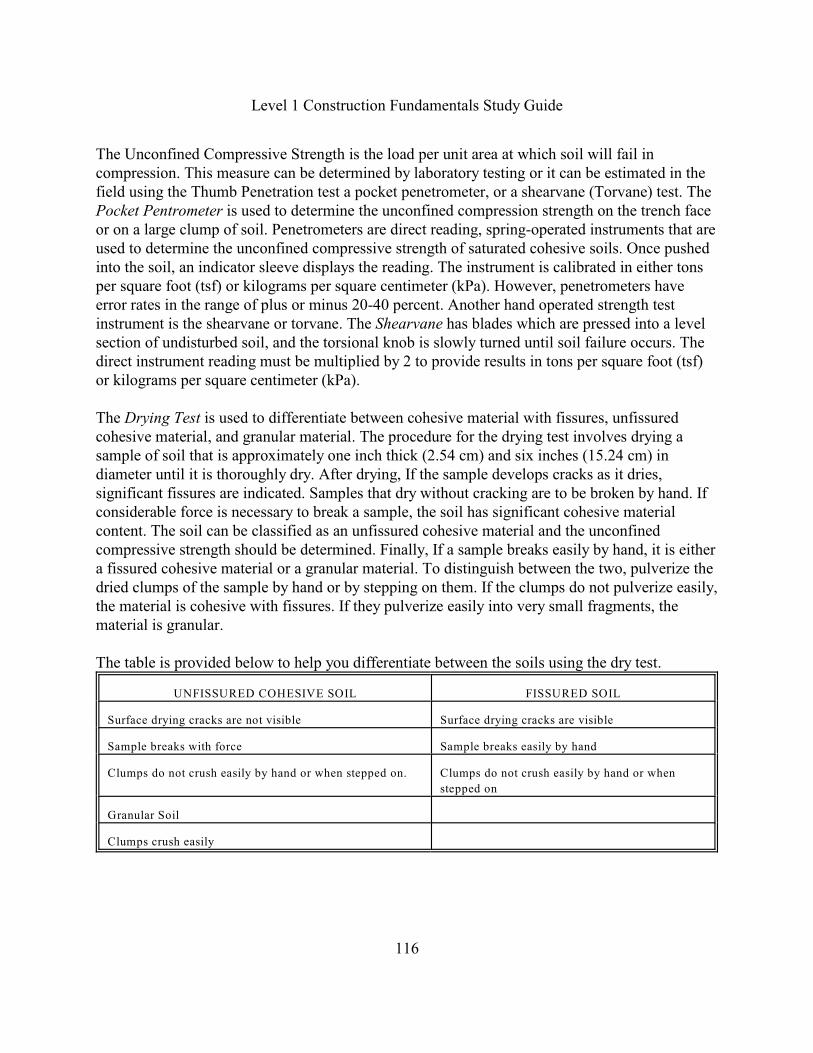
Level 1 Construction Fundamentals Study Guide
116
The Unconfined Compressive Strength is the load per unit area at which soil will fail incompression. This measure can be determined by laboratory testing or it can be estimated in thefield using the Thumb Penetration test a pocket penetrometer, or a shearvane (Torvane) test. ThePocket Pentrometer is used to determine the unconfined compression strength on the trench faceor on a large clump of soil. Penetrometers are direct reading, spring-operated instruments that areused to determine the unconfined compressive strength of saturated cohesive soils. Once pushedinto the soil, an indicator sleeve displays the reading. The instrument is calibrated in either tonsper square foot (tsf) or kilograms per square centimeter (kPa). However, penetrometers haveerror rates in the range of plus or minus 20-40 percent. Another hand operated strength testinstrument is the shearvane or torvane. The Shearvane has blades which are pressed into a levelsection of undisturbed soil, and the torsional knob is slowly turned until soil failure occurs. Thedirect instrument reading must be multiplied by 2 to provide results in tons per square foot (tsf)or kilograms per square centimeter (kPa).
The Drying Test is used to differentiate between cohesive material with fissures, unfissuredcohesive material, and granular material. The procedure for the drying test involves drying asample of soil that is approximately one inch thick (2.54 cm) and six inches (15.24 cm) indiameter until it is thoroughly dry. After drying, If the sample develops cracks as it dries,significant fissures are indicated. Samples that dry without cracking are to be broken by hand. Ifconsiderable force is necessary to break a sample, the soil has significant cohesive materialcontent. The soil can be classified as an unfissured cohesive material and the unconfinedcompressive strength should be determined. Finally, If a sample breaks easily by hand, it is eithera fissured cohesive material or a granular material. To distinguish between the two, pulverize thedried clumps of the sample by hand or by stepping on them. If the clumps do not pulverize easily,the material is cohesive with fissures. If they pulverize easily into very small fragments, thematerial is granular.
The table is provided below to help you differentiate between the soils using the dry test.
UNFISSURED COHESIVE SOIL FISSURED SOIL
Surface drying cracks are not visible Surface drying cracks are visible
Sample breaks with force Sample breaks easily by hand
Clumps do not crush easily by hand or when stepped on. Clumps do not crush easily by hand or when
stepped on
Granular Soil
Clumps crush easily
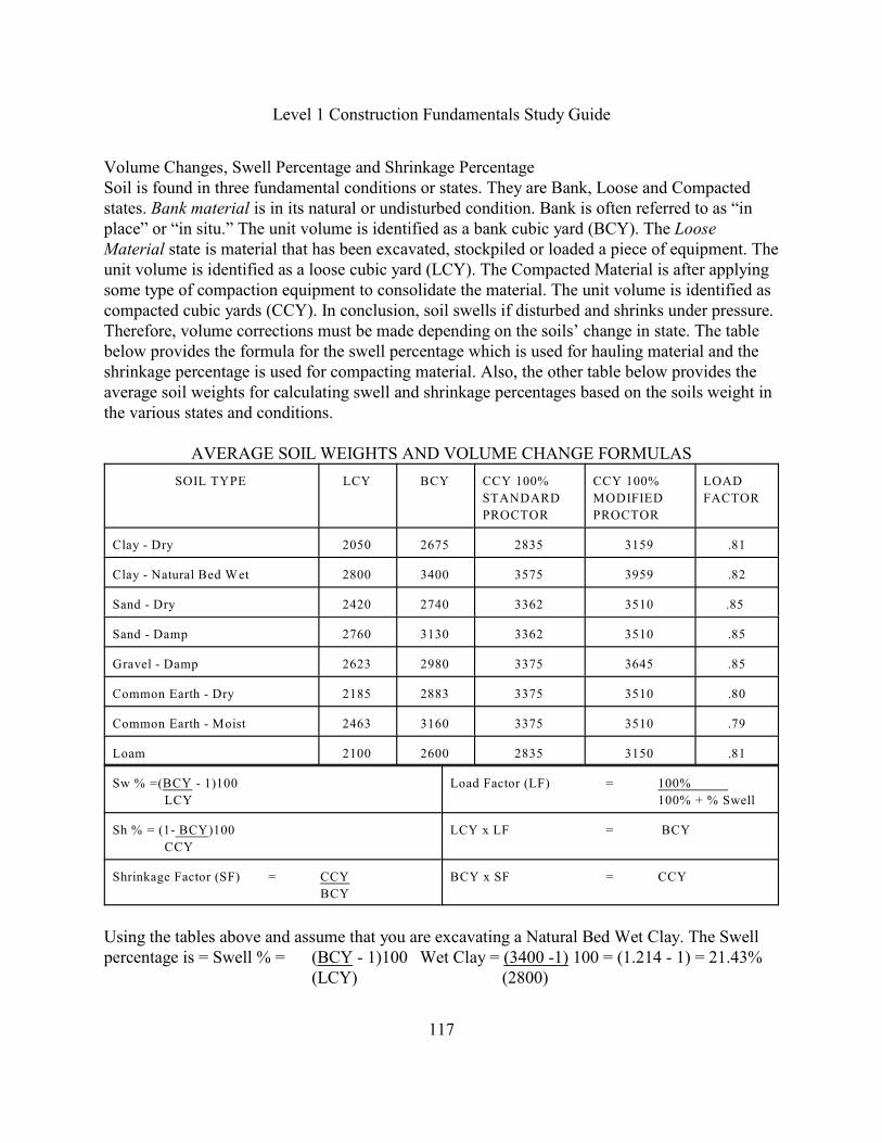
Level 1 Construction Fundamentals Study Guide
117
Volume Changes, Swell Percentage and Shrinkage PercentageSoil is found in three fundamental conditions or states. They are Bank, Loose and Compactedstates. Bank material is in its natural or undisturbed condition. Bank is often referred to as “inplace” or “in situ.” The unit volume is identified as a bank cubic yard (BCY). The LooseMaterial state is material that has been excavated, stockpiled or loaded a piece of equipment. Theunit volume is identified as a loose cubic yard (LCY). The Compacted Material is after applyingsome type of compaction equipment to consolidate the material. The unit volume is identified ascompacted cubic yards (CCY). In conclusion, soil swells if disturbed and shrinks under pressure.Therefore, volume corrections must be made depending on the soils’ change in state. The tablebelow provides the formula for the swell percentage which is used for hauling material and theshrinkage percentage is used for compacting material. Also, the other table below provides theaverage soil weights for calculating swell and shrinkage percentages based on the soils weight inthe various states and conditions.
AVERAGE SOIL WEIGHTS AND VOLUME CHANGE FORMULAS
SOIL TYPE LCY BCY CCY 100%
STANDARD
PROCTOR
CCY 100%
MODIFIED
PROCTOR
LOAD
FACTOR
Clay - Dry 2050 2675 2835 3159 .81
Clay - Natural Bed Wet 2800 3400 3575 3959 .82
Sand - Dry 2420 2740 3362 3510 .85
Sand - Damp 2760 3130 3362 3510 .85
Gravel - Damp 2623 2980 3375 3645 .85
Common Earth - Dry 2185 2883 3375 3510 .80
Common Earth - Moist 2463 3160 3375 3510 .79
Loam 2100 2600 2835 3150 .81
Sw % =(BCY - 1)100
LCY
Load Factor (LF) = 100%
100% + % Swell
Sh % = (1- BCY)100
CCY
LCY x LF = BCY
Shrinkage Factor (SF) = CCY
BCY
BCY x SF = CCY
Using the tables above and assume that you are excavating a Natural Bed Wet Clay. The Swellpercentage is = Swell % = (BCY - 1)100 Wet Clay = (3400 -1) 100 = (1.214 - 1) = 21.43%
(LCY) (2800)
Level 1 Construction Fundamentals Study Guide
118
Now assume that you are compacting a wet sand around the structure. The shrinkage percentageis:
Shrinkage % = (1- BCY)100 Damp Sand = (1 - 3,130) 100 = (1 - .892) = 10.8% CCY 3,510
Compaction is defined as the voids in the soil are reduced as portions of the air and moisture aredriven out by the use of mechanical compaction equipment such as rollers, vibrating rollers andtampers. Reduced voids and increased density produce a more stable earth fill., which willprovide a greater weight carrying capacity.
A standard laboratory test called a Proctor Test has been developed to evaluate a soil’s moisture-density relationship under specified compaction conditions. Actually, there are two Proctor testswhich have been standardized by the American Society for Testing Materials and (ASTM) andthe American Association of State Highway and Transportation Officials (AASHTO). These arethe Standard Proctor Test and the Modified Proctor Test.
The Standard Proctor Test is performed using a steel cylinder mold 4 inch in diameter with aheight of 4.59 inches and it is filled with a sample of the proposed material in three layers. Eachlayer is struck with 25 blows from a 5.5-pound, 2 inch diameter hammer dropped from a heightof 12 inches. The Modified Proctor Test is performed using the same cylinder and the sample isplaced in 5 layers. Each layer is struck with 25 blows with a 10-pound, 2 inch diameter hammerdropped from a height of 18 inches (stroke). The Modified Proctor is specified for fill materialdesignated for use under areas where high design loads are anticipated such as airport run waysand paved areas.
The relationship between moisture content and density of the soil is similar with most soils.Therefore, the amount of moisture required for the soil to attain its maximum density undercompaction is called the Optimum Moisture Content. The Optimum Moisture Content is theprimary factor that will determine if the desired density will be achieved in the least number ofpasses. Normally the Technical Specifications specify the proctor test that will be utilized, thedensity percentage that must be achieved and the optimum moisture content range.
Another factor that will effect whether density is attained is the thickness of the compactedmaterial normally referred to as the lift. The normal lift for compaction purposes is between 6inches and 12 inches.
Level 1 Construction Fundamentals Study Guide
119
Soil Mechanics ExerciseQuestions 1 through 16 pertain to the Soil Investigation Report and Soil Boring Procedures andthe Relative Density and Consistency Table provided at the end of this exercise. Answer thefollowing questions. 1. The Soil Report discusses the Penetration Resistance “N” Blow Count Summation
procedure, What is the correct summation procedure?
A. Add Blow Counts 1 and 2.B. Add Blow Counts 1 and 3.C. Add Blow Counts 2 and 3.D. Add Blow Counts 1, 2, and 3.
2. What type of hammer and fall distance was utilized for sampling the soil borings?
A. a 5-pound hammer falling 12-inches.B. a 10-pound hammer falling 18-inches.C. a 100-pound hammer falling 18-inches.D. a 140-pound hammer falling 30-inches.
3. Which party is responsible for comparing the soil borings to the standard RelativeDensity and Consistency Table provided in the Soil Report?
A. Owner.B. Vendor.C. Contractor.D. Architect/Engineer.
4. What does the abbreviation bpf mean?
A. Bulk per foot.B. Bank per foot.C. Blows per foot.D. Borings per foot.
5. What does the abbreviation SPT mean?
A. Stiff Penetration Test.B. Standard Proctor Test.C. Standard Penetration Test.D. Society for Proctor Testing.

Level 1 Construction Fundamentals Study Guide
120
Soil Mechanics Exercise
6. Which organization established the penetration test boring procedures?
A. Testing Services.B. Standard Penetration Testing.C. Society for Proctor Testing.D. American Society for Testing and Materials.
7. What is the Ground Elevation for Soil Boring #5?
A. 682.3'B. 683.3'
C. 697.8'D. 807.0'
8. At what depth did they hit water during drilling for Soil Boring #5?
A. 0.0 Feet.B. 1.0 Foot.C. 2.5 FeetD. 15.0 Feet
9. Using Soil Boring #5, What is the Penetration Resistance “N” at 4 Feet in bpf?
A. 3B. 6C. 7D. 10
10. Using Soil Boring #5, is there any unsuitable soil?
A. Organic Topsoil.B. Rock and Boulders.C. Very Stiff Clay and Gravel.D. Loose to Very Loose Brown Fine to Course Sand.
Level 1 Construction Fundamentals Study Guide
121
Soil Mechanics Exercise
11. Using Soil Boring #5. What is the depth of the unsuitable soil in feet?
A. 0.00'B. 1.00'C. 2.50'D. 3.08'
12. What is the Soil Classification for Boring #5 shown at 6 feet?
A. Organic Topsoil.B. Rock and Boulders.C. Very Stiff Clay and Gravel.D. Loose to Very Loose Brown Fine to Course Sand.
13. Using the Relative Density and Consistency Table, Soil Boring #5 and assume thePenetration Resistance “N” is 7. What is the material description from the table?
A. Soft.B. Loose.C. Medium Stiff.D. Medium Dense.
14. At what depth was Boring #5 drilling operation stopped?
A. 0.0 Feet.B. 1.0 Foot.C. 2.5 FeetD. 15.0 Feet
15. Assume the Penetration Resistance “N” is 29 for a clay, from the Relative Density andConsistency table what is the material description?
A. Dense.B. Very Stiff.C. Medium Stiff.D. Medium Dense.

Level 1 Construction Fundamentals Study Guide
122
Soil Mechanics Exercise
16. Using the Relative Density and Consistency table, If the soil boring indicated a Sand whatterm are you looking for at the top of the Table?
A. Consistency.B. Medium Stiff.C. Medium Dense.D. Relative Density.
17. Which of the following soils is considered cohesionless?
A. Silt.B. ClayC. Gravel.D. Topsoil.
18. Which of the following soils is considered cohesive?
A. ClayB. Sand.C. Gravel.D. Topsoil.
19. Which of the following tests is performed on cohesionless soil to determine thedistribution of grain size?
A. Vane Test.B. Sieve Analysis.C. Atterberg Limits. D. Penetration Test.
20. Which of the following techniques is used to determine the liquid, plastic, semisolid, andsolid states of consistency for a cohesive soil?
A. Vane Test.B. Sieve Analysis.C. Atterberg Limits. D. Penetration Test.
Level 1 Construction Fundamentals Study Guide
123
Soil Mechanics Exercise
21. Which of the following terms refers to the ability of water to flow through a soil bytraveling through the void spaces?
A. Capillarity.B. Frost heave.C. Permeability.D. Ground Water Table.
22. What are the most commonly used soil classification systems based on grain size?
A. Atterberg Limits and Permeability.B. The U.S. Department of Agriculture (USDA) Textural Classification Scheme and
the National Bureau of Standards Report BSS-121. C. The Construction Specification Institute’s Master Format and the U.S.
Governments Master Work Breakdown Structure (WBS).D. Unified Soil Classification System (USCS) and the American Association of State
Highway and Transportation Officials (AASHTO).
23. What is the earth material drawn from an excavation called?
A. Spoil.B. Saturated Soil.C. Submerged Soil.D. Cohesionless Soil.
24. What type of soil is the most dangerous because the excavated faces appear to be solidand stable, but they are drastically affected by water, wind, and pressure?
A. Clay.B. Sand.C. Gravel.D. Stable Rock.
25. According to OSHA, what is the minimum ratio for a layered soil system?
A. 1H:1VB. 3H:1VC. 4H:1VD. 1H:4V.
Level 1 Construction Fundamentals Study Guide
124
Soil Mechanics Exercise26. A small amount of material suddenly separates from the face of an excavation and
trickles or rolls down into the excavation. What is the visual inspection term called?
A. Spalling.B. Heaving.C. Toppling.D. Raveling.
27. The layers on the face of the excavation slope at a ratio of four horizontal to one vertical(4H:1V) or greater. What is the visual inspection term called?
A. Sliding.B. Toppling.C. Undercutting.D. Sloped system.
28. There is upward water flow into the bottom of the excavation. What is the visualinspection term called?
A. Boiling.B. Sloughing.C. Submerged.D. Surcharge Load.
29. The soil has sunk on the horizontal surface. What is the visual inspection term called?
A. Boiling.B. Bulging.C. Heaving.D. Subsidence.
30. The soil is protruding from the face of the open excavation into the excavation. What isthe visual inspection term called?
A. Boiling.B. Bulging.C. Heaving.D. Subsidence.

Level 1 Construction Fundamentals Study Guide
125
Soil Mechanics Exercise
31. the soil is protruding up from the bottom of the excavation. What is the visual inspectionterm called?
A. Boiling.B. Bulging.C. Heaving.D. Subsidence.
32. the soil has open cracks on the horizontal ground or on the open face of the excavation.What is the visual inspection term called?
A. Fissure.B. Bulging.C. Sloughing.D. Subsidence.
33. What is the term for an excessive vertical load caused by the spoil pile or constructionequipment being too close to the trench edge?
A. Impact load.B. Undercutting.C. Underpinning.
D. Surcharge load.
34. What do the field thumb penetration, pocket penetrometer and the shearvane measure?
A. Shear Stress.B. Impact Load.C. Surcharge Load.D. Unconfined Compressive Strength.
35. Which field manual test is used to differentiate between cohesive material with fissures,unfissured cohesive material, and granular material?
A. Pat Test.B. Drying Test.C. Plasticity Test.D. Dry Strength Test.
Level 1 Construction Fundamentals Study Guide
126
36. Which field manual test checks for a cohesive soil?
A. Pat Test.B. Drying Test.C. Plasticity Test.D. Thumb Penetration Test.
37. Which field manual test is used to determine the presence of a cohesive clay or silt?
A. Pat Test.B. Drying Test.C. Plasticity Test.D. Thumb Penetration Test.
38. What is another name for a soil that contains equal parts of sand, silt and clay?
A. Spoil.B. Loam. C. Moist Soil.D. Common Earth.
39. Which of the following soil has no cohesive strength?
A. Clay.B. Moist Soil.C. Layered Soil.D. Granular Soil.
40. What is the soil state called if it is in its natural, or in place or in situ or undisturbed state?
A. Bank.B. LooseC. Solid.D. Compacted.
41. What is the soil state called when the soil is excavated?
A. Bank.B. LooseC. Solid.D. Compacted.
Level 1 Construction Fundamentals Study Guide
127
Soil Mechanics Exercise
42. Using the Average Soil Weights Table, What is the swell percentage using a Loam?
A. 08.3%B. 23.8%C. 31.9%D. 81.0%
43. Using the Average Soil Weights Table, What is the shrinkage percentage for a DampSand under the Modified Proctor method, What is the shrinkage percentage? .
A. 10.8B. 12.1C. 13.4D. 85.0
44. Which of the following is the primary factor that will determine if 97% density using the
Modified Proctor Test will be achieved in a predetermined number of passes?
A. Soil Type.B. Moisture Content.C. Swell Percentage.D. Shrinkage Percentage.
45. Which of the following procedures describes the Modified Proctor Test?
A. It uses a 5-pound hammer dropped from a height of 12 inches.B. It uses a 10-pound hammer dropped from a height of 18 inches.C. It uses a 13,000 pound hammer dropped from a height of 20 feet.D. It uses a 140-pound hammer dropped from a height of 30 inches.
46. Which of the following procedures describes the Standard Proctor Test?
A. It uses a 5-pound hammer dropped from a height of 12 inches.B. It uses a 10-pound hammer dropped from a height of 18 inches.C. It uses a 13,000 pound hammer dropped from a height of 20 feet.D. It uses a 140-pound hammer dropped from a height of 30 inches.
Level 1 Construction Fundamentals Study Guide
128
Soil Mechanics Exercise
47. What is the normal lift range in inches stated in the documents for attaining the specifieddensity percentage when compacting structural fill?
A. 6 - 12.B. 13 - 24. C. 25 - 48. D. 49 - 60.
48. Which document specifies the Proctor Test and the percentage range and the OptimumMoisture Content?
A. Bid Documents.B. General Requirements.C. Technical Specifications.D. Supplementary Conditions.
49. Which test is specified for fill material designated for use under areas where high designloads are anticipated such as airport run ways and paved areas?
A. Shearvane.B. PenetrometerC. Standard Proctor.D. Modified Proctor.
50. The Soil Tables and formulas contain the abbreviation BCY, What does BCY mean?
A. Bulk Cubic Yards.B. Bank Cubic Yards.C. Basic Cubic Yards.D. Borrow Cubic Yards.
51. Which test instrument measures the unconfined compressive strength of soil?
A. Standard Proctor.B. Modified Proctor.C. Pocket Penetrometer.D. Standard Penetration.
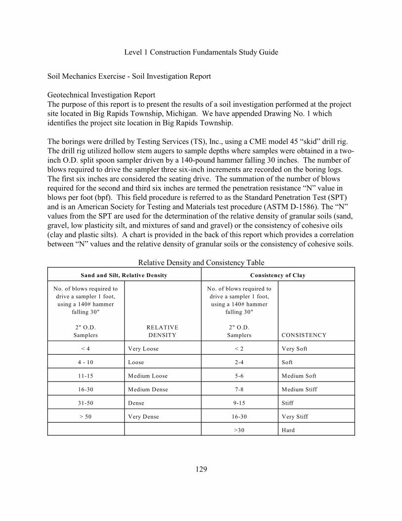
Level 1 Construction Fundamentals Study Guide
129
Soil Mechanics Exercise - Soil Investigation Report
Geotechnical Investigation Report The purpose of this report is to present the results of a soil investigation performed at the projectsite located in Big Rapids Township, Michigan. We have appended Drawing No. 1 whichidentifies the project site location in Big Rapids Township.
The borings were drilled by Testing Services (TS), Inc., using a CME model 45 “skid” drill rig. The drill rig utilized hollow stem augers to sample depths where samples were obtained in a two-inch O.D. split spoon sampler driven by a 140-pound hammer falling 30 inches. The number ofblows required to drive the sampler three six-inch increments are recorded on the boring logs. The first six inches are considered the seating drive. The summation of the number of blowsrequired for the second and third six inches are termed the penetration resistance “N” value inblows per foot (bpf). This field procedure is referred to as the Standard Penetration Test (SPT)and is an American Society for Testing and Materials test procedure (ASTM D-1586). The “N”values from the SPT are used for the determination of the relative density of granular soils (sand,gravel, low plasticity silt, and mixtures of sand and gravel) or the consistency of cohesive oils(clay and plastic silts). A chart is provided in the back of this report which provides a correlationbetween “N” values and the relative density of granular soils or the consistency of cohesive soils.
Relative Density and Consistency Table
Sand and Silt, Relative Density Consistency of Clay
No. of blows required to
drive a sampler 1 foot,
using a 140# hammer
falling 30"
2" O.D.
Samplers
RELATIVE
DENSITY
No. of blows required to
drive a sampler 1 foot,
using a 140# hammer
falling 30"
2" O.D.
Samplers CONSISTENCY
< 4 Very Loose < 2 Very Soft
4 - 10 Loose 2-4 Soft
11-15 Medium Loose 5-6 Medium Soft
16-30 Medium Dense 7-8 Medium Stiff
31-50 Dense 9-15 Stiff
> 50 Very Dense 16-30 Very Stiff
>30 Hard

Level 1 Construction Fundamentals Study Guide
130
Soil Mechanics Exercise - Soil Boring #5

Level 1 Construction Fundamentals Study Guide
131
Psychrometry and the Psychrometric ChartThis is the field of study concerned with the behavior of atmospheric air. Air in the atmosphere isa mixture of gases including oxygen and nitrogen, and water vapor. When one wishes tocondition an air space to create comfort for the occupants of the space, one will make changes inimportant properties of the air, including the temperature and the humidity. The impact of thesechanges on the comfort of the occupants is determined by considering the changes in a number ofother properties, which could result. The most common approach to evaluate this impact is byusing a chart solution of a number of thermodynamic relationships.
The psychrometric chart is a representation of all the important properties of atmospheric air andthe relationships between them. There are a number of properties shown, and a great many axeswhich run in different, often curving directions. The various properties and the direction of theappropriate axis are shown below.

Level 1 Construction Fundamentals Study Guide
132
Problems in psychometrics are solved by connecting lines on any two intersecting axes toidentify a point which represents the properties of the air under the conditions of the problem.The remaining properties can be read on the other axes.
Level 1 Construction Fundamentals Study Guide
133
Psychrometry Example
Using the Psychrometric chart, and given a Dry-Bulb (DB) Temperature is 90 degrees Fahrenheitand the Wet-bulb (WB) Temperature is 76 degrees Fahrenheit, Determine the following values.
First, what is the Relative Humidity (RH) value from the chart?
This found by following the downward curving lines and it reads greater than 50% andless than 60%. Therefore, the interpolation would be 54%.
Second, what is the Humidity Ratio (HR) value from the chart?
This is found by using the point of intersection between the Dry-bulb and the Wet-BulbTemperatures and then drawing a horizontal line to the right side. The Humidity ratioreads 0.0162. This is the humidity ratio or the pounds of moisture per pound of dry air.
Third, What is the Dew Point (DP) value from the chart?
This is found by using the point of intersection between the Dry-Bulb and the Wet-BulbTemperatures and then drawing a horizontal line to the left side. The Dew Point reads 71degrees F. This is the Dew Point of saturation.
Fourth, What is the Enthalpy value from the chart?This is found using the point of intersection between the Dry-Bulb and the Wet-BulbTemperatures and then following the diagonal line to the left side. The Enthalpy reads39.6 Btu per lb of dry air.
Heat is measured in British Thermal units, or BTU. A BTU is the amount of heat required toraise 1 pound of water 1 degree F. The rate of heat flow is measured in BTU per hour abbreviatedbtuh. Heating, Ventilating and Air Conditioning (HVAC systems use fluids to transport heat andcold to satisfy loads and maintain comfort. The fluids such as air, water, steam, and refrigerantare used to transport the heat and cold.
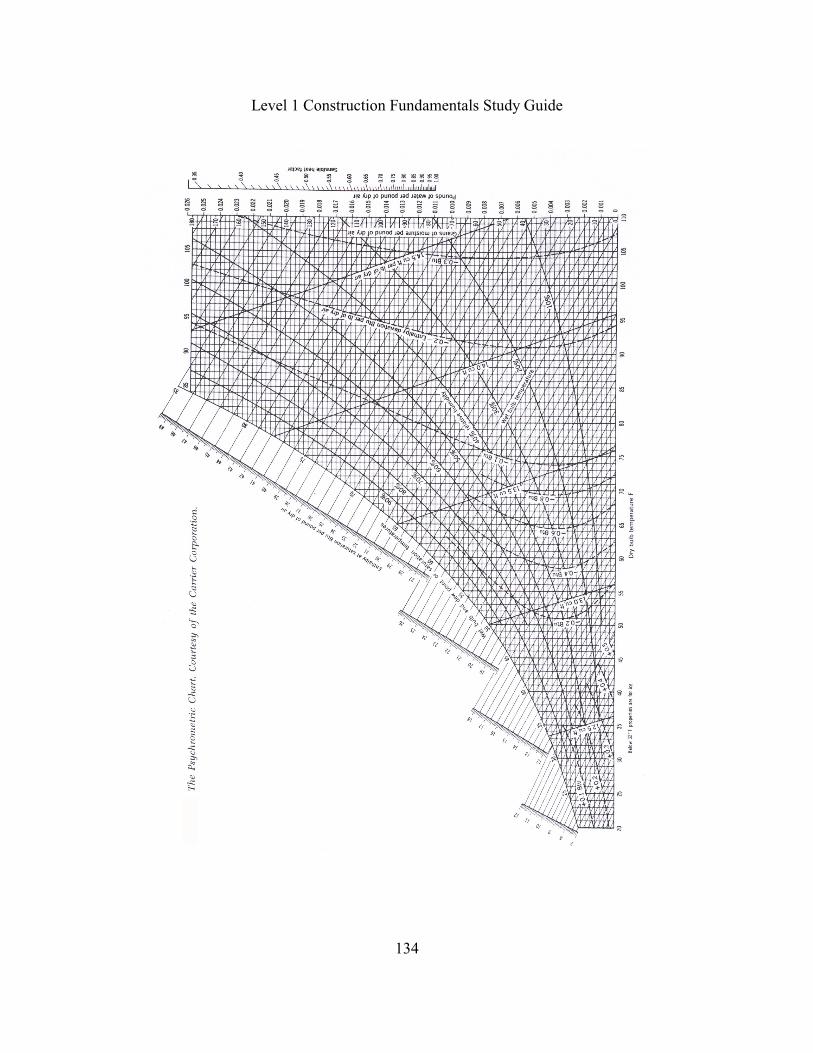
Level 1 Construction Fundamentals Study Guide
134

Level 1 Construction Fundamentals Study Guide
135
Psychrometric Exercise
Using the Psychrometric Chart and given a Dry Bulb Temperature of 85 degrees F and a WetBulb Temperature of 65F answer the following questions.
1. What is the Relative Humidity (RH) value?
A. 28B. 34C. 57D. 72
2. What is the Humidity Ratio (HR) value?
A. 0.0030B. 0.0088C. 30.0000D. 52.0000
3. What is the Dew Point (DP) value?
A. 0.0030 B. 0.0088C. 30.0000D. 52.0000
4. What is the Enthalpy value?
A. 0.0030 B. 0.0088C. 30.0000D. 52.0000
5. What is it called that measures the amount of heat required to raise the temperature of 1pound of water 1 degree Fahrenheit?
A. Enthalpy.B. Saturated.C. Relative Humidity.D. British thermal units.

Level 1 Construction Fundamentals Study Guide
136
Psychrometric Exercise
Using the Psychrometric Chart and given a Dry- Bulb Temperature of 75 degrees F and RelativeHumidity of 50% answer the following questions.
6. What is the Wet-Bulb (WB) value?
A. 56B. 63C. 70D. 90
7. What is the Humidity Ratio (HR) value?
A. 0.0092B. 28.5000C. 56.0000D. 69.0000
8. What is the Dew Point (DP) value?
A. 0.0092B. 28.5000C. 56.0000D. 69.0000
9. What is the Enthalpy value?
A. 0.0092B. 28.5000C. 56.0000D. 69.0000
10. What is another term for the total heat content of air?
A. Enthalpy.B. Saturated.C. Relative Humidity.D. British thermal units.