Embed Size (px)
Citation preview

ST:CA6A/5 February 2018 - 1 of 80 -
Company Directive
STANDARD TECHNIQUE: CA6A/5
Relating to the Installation of Underground Cables
Policy Summary
This technique forms the approved installation procedure for all underground cables,
which are installed within Western Power Distribution with the exception of pressure-
assisted cables at 33kV, 66kV and 132kV cables.
Serving the Midlands, South West and Wales
Gwasanaethu Canolbarth a De Orllewin Lloegr a Chymru
NOTE: The current version of this document is stored in the WPD Corporate Information Database. Any other copy in electronic or printed format may be out of date. Copyright 2018 Western Power Distribution

ST:CA6A/5 February 2018 - 2 of 80 -
IMPLEMENTATION PLAN
Introduction
This technique forms the approved installation procedure for all underground cables,
which are installed within Western Power Distribution with the exception of pressure-
assisted cables at 33kV, 66kV and 132kV cables.
Main Changes
The document has been updated to take into account the increase in joint hole sizes
required to accommodate the Lovink 33kV jointing system.
Recommendation that kerb lines are installed before cables are laid on new developments
Impact of Changes
No major change
Implementation Actions
Team managers to disseminate the information to their respective staff.
No formal training will be required.
Implementation Timetable
This Standard Technique can be implemented with immediate effect.

ST:CA6A/5 February 2018 - 3 of 80 -
REVISION HISTORY
Document Revision & Review Table
Date Comments Author
February 2018 33kV joint bay drawing changed to reflect
the Lovink 33kV joint system
(drawing 3.7.3, page 33 )
Recommendation that kerb lines are installed
before cables are laid on new developments
(Section 4.1)
Richard Summers
January 2017 Double 132kV circuits shown along with risk
assessment that needs to be carried out, this
risk assessment shall be saved in the health
and safety file.
Drawings for single and double 132kV
circuits including Surf duct and joint bays.
Clarification on bedding and blinding of
cable ducts in stone dust.
Removal of internal beads in all forms of
jointing of SDR 11 HDD ducts.
Guidance on cleating of cables.
Guidance on the running of 70mm² HDC
with other cable circuits and the need to
comply with EE 89.
Number of Surf ducts reduced to one.
Addition of Gorilla duct tape to hold single
core cables in trefoil.
Peter White
July 2013 Multiple circuits for 33kV shown Peter White
ST:CA6A/5 February 2018 - 4 of 80 -
UNDERGROUND CABLE INSTALLATION
CONTENTS
1.0 INTRODUCTION Page 6
2.0 PREPARATION Page 7
3.0 EXCAVATION Page 7
3.1 Trial Holes
3.2 Excavation and Waste
3.3 Abnormal Trench Depths, Shuttering, and Unstable Ground
3.4 Coordinated Trenching
3.5 Positioning of Utilities' Apparatus in Pavement
3.6 Use of Trench Plates
3.7 Pipes and Ducts
3.8 Joint Hole Dimensions
3.9 Preparation of 33kV Joint Holes
3.10 Installation of Cross Bonding Link Boxes on 66kV Flat Spaced Circuits
3.11 Landfill Tax
3.12 Contaminated Ground
3.13 Bridge Crossings
3.14 Substations and Buildings
3.14.1 Work in Buildings, including Indoor Substations
3.15 Earth Wires
3.16 Work Near Other Cables
3.17 Laying Cables Near Trees
3.18 Tree Planting Restrictions near underground cables
3.19 Railways
3.20 Motorways
3.21 Trenchless Technology
4.0 LAYING CABLE Page 45
4.1 Preparation
4.1.1 Precautions in Cold Weather
4.1.2 Cable Drums - Handling and Positioning
4.1.3 Winch Positioning
4.1.4 Cable Bedding
4.1.5 Cable Rollers - Positioning
4.1.5.1 Winch Pulling
4.1.5.2 Hand Pulling

ST:CA6A/5 February 2018 - 5 of 80 -
4.2 Cable Pulling
4.2.1 Cable Attachments
4.2.1.1 Attachment of Cable Stocking To Cable
4.2.1.2 Attachment of Pulling Rope To Stocking
4.2.2 Rope Bonds
4.2.2.1 Steel Wire Rope
4.2.3 Methods
4.2.3.1 Winch Pulling
4.2.3.2 Laying Cable from Moving Drum Trailer
4.2.3.3 Pulling in by Hand
4.2.3.4 Bond Pulling
4.2.4 Flaking and Coiling Cable
4.2.4.1 Coiling Cable
4.2.4.2 Flaking Cable
4.2.5 Pulling Single Core 33kV EPR and Single Core 11kV EPR Cable
4.3 Cleating
4.3.1 Horizontal Straight Runs
4.3.2 Horizontal Bends
4.3.3 Cable Runs other than Horizontal and Straight
4.4 Cable End Capping
4.4.1 Cold Shrink Cap
4.4.2 Heat Shrink Cap
4.4.3 Denso Tape Seals
5.0 REINSTATEMENT Page 73
5.1 Backfill to Marker Tape
5.2 Re-use of Excavated Material
5.3 Compacting
5.4 Reinstatement above Marker Tape
6.0 PRIOR TO ENERGIZATION OF THE ALL CABLE
CIRCUITS Page 75

ST:CA6A/5 February 2018 - 6 of 80 -
UNDERGROUND CABLE INSTALLATION
1.0 INTRODUCTION
1.1 This document has been produced for all staff engaged in the installation of
cables. It must be noted that the scope of this document does not cover the
installation of pressure-assisted 33kV, 66kV and 132kV cables, as they are
supplied and installed by the cable manufacturer concerned or some other selected
installer.
1.2 It is the responsibility of all staff engaged in underground cable installation to
comply with appropriate legislation. The legal framework for health and safety at
work is set down in a variety of legislation - Acts of Parliament, and Statutory
Regulations. A range of guidance providing information on recognised good
practice supports the legal requirements. This guidance is in the form of
Approved Codes of Practice (issued by the Health and Safety Commission) and
guidance notes, booklets and leaflets (issued by the Health and Safety Executive,
trade organisations, professional institutions etc.). There are also British and
International Standards.
1.3 The principle legislation, guidance etc. relevant to underground cable installations
is as follows: -
- Health and Safety at Work Act 1974
- Electricity, Safety, Quality and Continuity Regulations 2002
- Electricity at Work Regulations 1989
- Control of Pollution Act 1990
- Controlled Waste Regulations 1991
- New Roads and Streetworks Act 1991 (NRSWA)
- Traffic Management Act 2004
- Management of Health and Safety at Work Regulations 1992
- Workplace (Health, Safety, and Welfare) Regulations 1992
- Provision and Use of Work Equipment Regulations 1992
- Manual Handling Regulations 1992
- Construction (Design and Management) Regulations 2015
- WPD Distribution Safety Rules
- HSG 47 Avoiding Danger from Underground Services.
- NJUG Publications - Volume 1 “NJUG Guidelines on the Positioning and Colour
Coding of Underground Utilities’ Apparatus “
- NJUG Publications - Volume 4 "NJUG Guidelines for the Planning,
Installation and Maintenance of Utility Apparatus in Proximity to Trees"
- HSG 66 “Protection of Workers and the General Public during the
Development of Contaminated Land”

ST:CA6A/5 February 2018 - 7 of 80 -
2.0 PREPARATION
Before any work is carried out, the following items must have been completed
and copies of relevant documents are available at the site of the works: -
2.1 Accurate plans showing all apparatus (WPD's and other utilities or service
providers) in vicinity of work site.
2.2 Plan of proposed new cable route.
2.3 Easements/landowners notified.
2.4 Highway authorities and statutory undertakers notified sufficiently in advance to
meet NRSWA requirements.
2.5 Correct signing & guarding implemented as per ST: HS14D.
3.0 EXCAVATION
3.1 Trial Holes
Unless it is known from co-ordination drawings that the route is relatively clear of
obstructions, trial holes shall be taken at proposed joint locations and at such other
positions along the route as is necessary to ascertain the practical positioning of
the cable.
Trial holes should generally be at right angles to the run of cables and at least
150mm deeper than the proposed trench.
Surface covers belonging to other utilities may give a guide to the location of their
equipment.
3.2 Excavation and Waste
Refer to figures 3.2a, 3.2b & 3.2c and table 3.2 for details of specific trench
dimensions. If it is necessary to lay Surf fibre ducts in the same trench as the
WPD mains cables, refer to drawings G 4064.33, G4064.66 and G4065 for
dimensions and layout.
The actual width of trench depends on the following factors: -
- Type and size of cable being laid.
- Number of cables being laid in same trench.
- If low and high voltage cables being laid in same trench, the effect on the
cable ratings must be considered.
- Whether ducts are being used.


ST:CA6A/5 February 2018 - 14 of 80 -
- If mechanical means are being used in order to excavate the trench in order to
install a single cable, then the width can be as narrow as 150mm.
- The trench width must also allow for mechanical compaction.
Trenches should: -
(a) Have lines, levels, and contours to suit continuous pulling of cable by
winch.
(b) Be as straight as possible. Where bends are unavoidable the trench should
allow the cable to be installed at not less than its minimum-bending radius
using cable rollers.
(c) Be to the approved dimensions and normally have vertical sides which
should have a side support system (e.g. timbering), should the ground be
soft or loose.
(d) Have a firm and smooth contoured base.
(e) Be excavated with such precautions as are necessary to prevent damage to
the highway or ground surface from a slip or breaking away of the sides of
the trench. Cutting by machine (e.g. road saw, chain excavator or planer)
is preferred.
(f) Be excavated so that all railways, tramways, walls, roads, sewers, drains,
pipes, cables, structures, places, shall be secure against risk of subsidence
or damage, and shall be carried out to meet the requirements of the
authorities concerned.
(g) Where they pass from a footway to a roadway or at other positions where
a change of level is necessary, have a base that rises or falls gradually.
(h) Be cleared of water by pumping to prevent the risk of the trench
collapsing and hazard to the general public, especially trespassing
children. In locations where flooding can occur, measures shall be taken to
divert rainwater away from the trench (e.g. use of sandbags).
(i) Have provisions made during their excavation to cater for access of
persons and vehicles to property of places alongside the route.
(j) In concrete surfaces be cut through the concrete as per the HAUC
Specification for the Reinstatement of Openings in Highways.
(k) Where short lengths of ducts are installed, have a hole dug below the front
of the leading edge of duct-run so that anything that could be dragged into
the duct during cable pulling will fall into the hole instead.

ST:CA6A/5 February 2018 - 15 of 80 -
(l) If ground conditions in open terrain could lead to collapse of the trench
wall, the trench can be excavated with sloping sides. With machine
excavation, a standard 'V' shaped ditching bucket may be used.
Other works and properties, such as decorative walls and lawns, shall be
safeguarded against damage from excavated material by using some form of
sheeting. When machines are being used for excavation and the location of other
plant is known, the plant should be uncovered by hand excavation to reduce the
possibility of damage. If the excavation is likely to reduce the stability of any part
of any structure, work shall not be commenced unless adequate precautions are
taken to prevent the structure from collapse or deterioration. Flooding, or
vibration from heavy traffic can cause collapse of trench sides and subsidence of
adjacent structures. A trench side support system or shoring shall be used to avoid
this.
See ST: HS14B/3 Excavation and Shoring.
3.3 General 132kV Underground Cable Information
Typically 132kV circuits either start from overhead line terminal positions like an L4(M)
DT sealing end platform, see overleaf for sketch, or L7(C) DT sealing end platform or
from a substation on a three single phase 132kV sealing end structures, see drawing 3.3
for more information. With the sealing end platforms it is best to use individual cable
ladders for the three phases as this eliminates the minimum bending radius problems of
large cross sectional area (CSA) cables on the trident design cable ladders. The cables are
to be cleated to the cable ladders or structures using Ellis Patent Atlas two bolt cleats of
commensurate size for the respective cable. See below.
Ellis Patent Atlas two bolt cable cleat.
Bonding leads for 132kV circuits are 240mm² with the construction being plain or
concentric, all earthing and bonding of 132kV circuits shall comply with ENA ER C55/5
where the maximum induced voltage shall NOT exceed 65V.
It should be noted that if Surf Telecom ducts are to be run with 132kV circuits across
agricultural land then the ducts shall have 1000mm cover and there shall be a minimum
clearance between the Surf Telecom ducts and the 132kV circuits of 150mm.

ST:CA6A/5 February 2018 - 16 of 80 -
L4 (M) DT tower complete with sealing end platforms showing the trident style cable ladders.
These ladders will have minimum bending radius issues with large CSA cables.


ST:CA6A/5 February 2018 - 18 of 80 -
3.3.1 132kV Single Circuit cable Trench
A single 132kV circuit in its own trench is the preferred option of installing 132kV
circuits to a BSP or other location as this method of installation minimises the risk of
losing supply to the BSP or the overhead line, when compared to two 132kV
underground circuits in the same trench, as the double circuit in a single trench
configuration presents a high probability of hitting both circuits simultaneously with e.g.
a Horizontal Directional Drill (HDD), mechanical digger or other common mode failure
mechanism. The typical trench width for a single circuit is given in drawing 3.7.1 and the
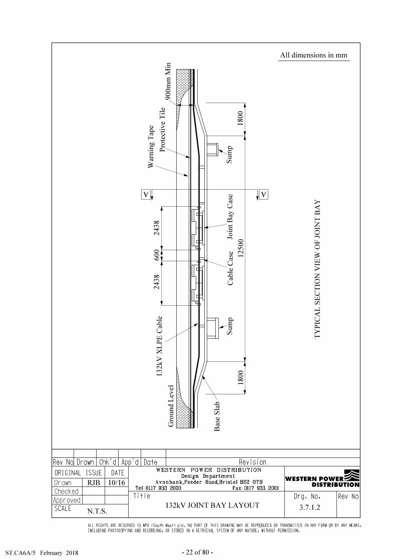
typical joint bay is shown in drawings 3.7.1.1, 3.7.1.2, 3.7.1.3 and 3.7.1.4.
If two circuits are to be run along the same route then the preferred option is to have the
centre to centre spacing of the two circuits set at 2500mm this provides thermal
independence of the circuits and also means a smaller cross sectional area cable can be
used as there will be no derating effects.
3.3.2 132kV Double circuit cable trench
The option of installing a two 132kV underground circuits into a single trench is
available but requires a risk assessment to be carried out with final sign off by the
requisite senior management, this risk assessment and sign off shall be kept in the Health
and Safety file for the particular underground cable project so that the information can be
reviewed at any time in the future if necessary.
This section aims to provide guidance on the management of dual 132kV circuits in the
same trench and recognizes the potential for increased network risk due to the creation of
a single point of failure and provides the guidance on assessing the level of risk and
identifying appropriate mitigation.
Distribution Managers and Major Projects Managers will have the following
responsibilities for all cases of where double 132kV circuits are laid in a single cable
trench for which they are responsible and which fall within their operational areas: -
The Identification and recording of the locations of all double 132kV circuits trenches
within their respective areas.
For each double 132kV circuit cable trench they shall identify and record the
following details: -
The number and cable rating of circuits contained within the trench.
The number of Customers supplied by those circuits.
Details of any Critical Customers and /or Interdependent Critical Infrastructure
supplied by those circuits e.g. Hospitals, Significant Food Manufactures or
Processes and Water/Oil/Gas/Sewage etc.
The recoverable demand / Customer numbers e.g. where 85% of connected
Customers are recoverable in switching time, this may result in a Low Risk
classification even though large numbers of customers are initially affected.

ST:CA6A/5 February 2018 - 19 of 80 -
The Criticality of the asset within the wider network.
The completion of an appropriate Risk Assessment for each asset. (See Risk score
sheet for double 132kV circuits in a single trench.)
Recording and retaining the unmitigated risk score (High/Medium/Low)
irrespective of any mitigating actions taken.
For this ST “risk” is the product of the likelihood and the consequence of both circuits
being damaged, and the loss of supply to all customers. When assessing the likelihood
consideration will be given to the route, surrounding land usage, is there an ability to
back feed the substation etc. When assessing the consequences, consideration should be
given to loss of multiple circuits e.g. loss of supplies to customers, the available supply
restoration options and the potential costs.
To aid in this assessment please refer to Appendix A clause A.3.3.1 Impact
Measurement and clause A.3.3.2 Actions arising from Risk Prioritisation for the
methodology to be used.


ST:CA6A/5 February 2018 - 25 of 80 -
TABLE 3.2 - NORMAL TRENCH DIMENSIONS - Three-Core Cable or Triplex.
Cable Type Location Trench Depth Trench Width
Single Cable
Min Cover
Over Cable
Trench Width
Two Cables
LV & Services Pavement or
private land 530mm 300mm 450mm 300mm
LV & Services Roadway
(ducts) 600mm 300mm 520mm 300mm
11kV (PICAS) Pavement or
private land 530mm 300mm 450mm 300mm
11kV (PICAS) Roadway
(ducts) 600mm 300mm 520mm 400mm
11kV (Triplex
EPR or XLPE)
Pavement or
private land 530mm 300mm 450mm 300mm
11kV (Triplex
EPR or XLPE)
Roadway
(ducts) 600mm 300mm 520mm 400mm
33kV H or HSL
Solid Type Cable all locations 900mm 300mm 750mm 600mm
- Single Underground Circuit using Single Core Cables (Laid in Trefoil)
Cable Type Locations Trench Depth Trench Width Min Cover over
Cable
132kV EPR or XLPE
laid in trefoil all locations 1098mm 850mm 900mm
66kV EPR or XLPE
laid in Trefoil all locations 1098mm 450mm 900mm
66kV EPR or XLPE
laid with 2D Flat
Spacing (630mm² or
larger c.s.a only)
all locations
Depends on diameter
of cable but
approximately
1050mm
550mm 900mm
33kV EPR or XLPE
laid in trefoil all locations 900mm 450mm 750mm
11kV (Single core
EPR) laid in trefoil
Pavement or private
land 530mm 300mm 450mm
11kV (Single core
EPR) laid in trefoil
Roadway
(ducts) 600mm 300mm 520mm
It is permissible to increase the trench depth for short lengths to avoid obstructions and overcome local engineering difficulties. When installing cables in agricultural land, it is necessary that the cable be laid at sufficient depth to allow for deep ploughing and cultivation. The recommended depths, to the top of the cable, as agreed with the National Farmers' Union are as follows:
All LV & 11kV cables - 1000mm depth All 33kV cables - 1000mm depth All 66kV cables - 1000mm depth All 132kV cables - 1000mm depth

ST:CA6A/5 February 2018 - 26 of 80 -
3.3 Abnormal Trench Depths, Shuttering, and Unstable Ground Shuttering with timber or other suitable material must be provided where it is
necessary to prevent danger from trench side collapse or falls of rock or other material from the side of the ground adjacent to the trench.
This requirement must be carefully considered where a person could be trapped or
buried or struck by material from any height. The Construction (Health, Safety, and Welfare) Regulations 1996 can be referred to for further guidance.
Where excavations deeper than normal are to be dug, reference should also be
made to ST: HS 14B – Excavation and Shoring, and BS 6031 (2009), which is the Code of Practice for Earthworks. This deals with the dangers of water draining into a deep excavation and also with the importance of having knowledge of the types of ground being excavated.
All excavation works shall be risk assessed prior to starting work in order to
determine whether appropriate shoring is required. As a guide excavations in excess of 1.2m deep shall be classified as 'deep excavations' by the ST: HS 14B and NRSWA, and, as such, the relevant highway authority shall be notified of the special condition.
In ground where subsidence is likely, the cable should be bedded in crushed
limestone or crushed granite dust with a pronounced snake, from one side of the cable trench to the other side of the cable trench, to allow for settlement. Damage may be caused to a cable termination by movement of the cable due to ground subsidence, and an anchor should be fitted to the cable with a loop provided to ensure that the minimum of stress is applied to the accessory.
3.4 Coordinated Trenching Coordinated trenching involves excavating one trench of suitable size to
accommodate all the mains to be laid by the various utilities (water, gas, BT etc.). The advantages are cheaper trenching, minimum disturbance to the public, and a lower likelihood of any undertaker damaging another's plant.
It is essential that early consultation takes place and full liaison between all
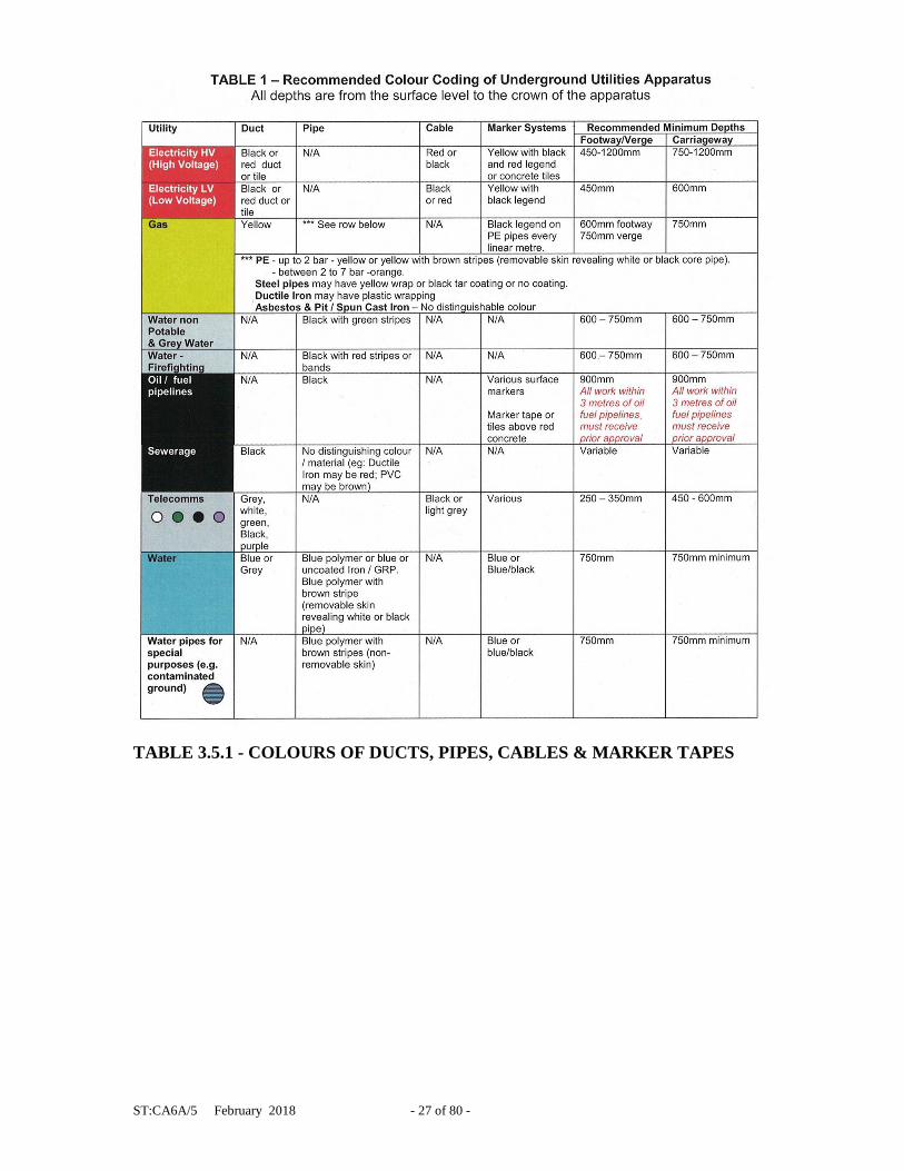
interested parties is imperative for the full benefits to be assured. 3.5 Positioning of Utilities' Apparatus in Pavement Figure 3.5, overleaf, shows the NJUG agreed standard positioning of utilities'
apparatus in a 2m wide new pavement and this shall normally be followed. If these clearances to other utilities' plant cannot be achieved refer back to the
relevant utility for guidance. The clearances to WPD cables should also allow for subsequent access and
jointing. Table 3.5.1, overleaf, details how other utilities' plant can be identified
underground.
ST:CA6A/5 February 2018 - 27 of 80 -
TABLE 3.5.1 - COLOURS OF DUCTS, PIPES, CABLES & MARKER TAPES

ST:CA6A/5 February 2018 - 28 of 80 -
TABLE 3.5.1 Continued - COLOURS OF DUCTS, PIPES, CABLES & MARKER
TAPES
3.6 Use of Trench Plates
Only fibreglass type trench plates (such as Technotrak ‘Safety Cross’ or Parker
‘Defiance Trench Cover’) will be used within WPD. For ease of ordering, these items have been set up on the E 5 system.
Trench plate use is restricted to footway excavations only where access to
properties is to be maintained. Trench plates must be used in conjunction with appropriate signing and guarding.
Trench plates shall not be left on site in isolation. A trench plate must be firmly fixed to the adjacent surfaces, preferably by using
pins at the corners. The plate must fit flush to the existing footway and any edge trips will be ramped with temporary tarmac.
A risk assessment will be completed on every occasion a trench plate is used. Trench plates shall not be used to defer permanent reinstatement.

ST:CA6A/5 February 2018 - 29 of 80 -
FIG 3.5 - TYPICAL CROSS-SECTION OF TRENCH SHOWING RELATIVE
POSITION OF MAINS
ST:CA6A/5 February 2018 - 30 of 80 -
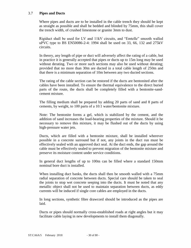
3.7 Pipes and Ducts
Where pipes and ducts are to be installed in the cable trench they should be kept as straight as possible and shall be bedded and blinded by 75mm, this shall cover the trench width, of crushed limestone or granite 3mm to dust.
Rigiduct shall be used for LV and 11kV circuits, and “Emtelle” smooth walled
uPVC type to BS EN50086-2-4: 1994 shall be used on 33, 66, 132 and 275kV circuits.
In theory, any length of pipe or duct will adversely affect the rating of a cable, but
in practice it is generally accepted that pipes or ducts up to 15m long may be used without derating. Two or more such sections may also be used without derating; provided that no more than 30m are ducted in a total cable length of 250m and that there is a minimum separation of 10m between any two ducted sections.
The rating of the cable section can be restored if the ducts are bentonited after the
cables have been installed. To ensure the thermal equivalence to the direct buried parts of the route, the ducts shall be completely filled with a bentonite-sand-cement mixture.
The filling medium shall be prepared by adding 20 parts of sand and 8 parts of
cements, by weight, to 100 parts of a 10:1 water/bentonite mixture. Note: The bentonite forms a gel, which is stabilized by the cement, and the
addition of sand increases the load-bearing properties of the mixture. Should it be necessary to remove this mixture, it may be flushed out of the ducts by using high-pressure water jets.
Ducts, which are filled with a bentonite mixture, shall be installed wherever
possible in a concrete surround but if not, any joints in the duct run must be effectively sealed with an approved duct seal. At the duct ends, the gap around the cable must be effectively sealed to prevent migration of the bentonite mixture and preserve its moisture content under service conditions.
In general duct lengths of up to 100m can be filled where a standard 150mm
nominal bore duct is installed. When installing duct banks, the ducts shall then be smooth walled with a 75mm
radial separation of concrete between ducts. Special care should be taken to seal the joints to stop wet concrete seeping into the ducts. It must be noted that any metallic object shall not be used to maintain separation between ducts, as eddy currents will be induced if single core cables are employed in the ducts.
In long sections, synthetic fibre drawcord should be introduced as the pipes are laid.
Ducts or pipes should normally cross-established roads at right angles but it may
facilitate cable laying in new developments to install them diagonally.
ST:CA6A/5 February 2018 - 31 of 80 -
3.8 Joint Hole Dimensions
Drawing G 4016 A gives the dimensions and layout for all standard joint holes
used in WPD.
3.9 Preparation of 66 and 33kV Joint Holes
As 66 and 33kV joints are basically flexible it is necessary to support the joints on
concrete slabs. Drawing 3.7.2, 3.7.2.A and 3.7.3 shows the recommended joint
bay layout. The length of slabbing will be dependant upon the particular joint
involved, (e.g. for trifurcating joints a length of 6 slabs should be used).
Three-slab width allows one slab each side of the joint as a working platform and
these outer slabs may be recovered once jointing is complete.
A granular sub-base will allow easy levelling of the slabs in addition this will also
assist with drainage of the working area if the area is wet. Sand bags beyond the
ends of the joint should support the cables, and be left in position once jointing is
complete.
3.10 Installation of Cross Bonding Link Boxes on 66 & 132kV Flat Spaced
Circuits
When installing 66kV or 132kV single core cables of conductor sizes of 630mm²
or larger then it becomes economical to consider laying the circuit in flat spaced
configuration where the spacing between the individual conductors can be D, 2D,
3D or 4D spacing where D is the diameter of an individual core, this will give the
circuit a slightly higher current rating but this will be offset by the increased cost
of the cross bonding link boxes. The design of the cross bonding system shall
comply with Electricity Network Association Engineering Recommendation
C55/4, refer to the Company Cable Engineer in Avonbank. When the link boxes
are installed in the ground the length of the bonding leads which connect the
joints to the link boxes must not exceed 8m.
This means that if the circuit is laid in the carriageway then the cross bonding link
boxes can be installed in the sidewalk; this will allow future maintenance on the
link boxes without having to get a lane closure. See drawing 3.10


ST:CA6A/5 February 2018 - 37 of 80 -
3.11 Landfill Tax
POL: EN 3, ST: EN 3A and ST: EN 3B sets out the regime for the disposal of
material excavated from sites. It defines inert and active waste and the
composition of mixed loads for the purposes of the interpretation of the HM
Customs and Excise Landfill Tax Levy.
Inactive or general waste incurs the lower rate of tax and is tightly defined. For
WPD purposes, materials such as rocks, soils, and concrete fall into this category.
Active waste includes plastics, tins, bitumen, paper and wood and the higher tax
rate applies. It is very important, therefore, that a mixed load is not corrupted with
unacceptable items of active waste such as compound tins, bits of cable, wood
shuttering etc. It is worth noting that the tax does make allowances for small
quantities of bitumen material including tarmac or asphalt in a load of soil dug up
for Utilities' street works. This qualifies at the lower tax rate if these incidental
amounts of active waste are considered to be no pollution risk.
3.12 Contaminated Ground
Often the local knowledge of a site is the single most important aspect when
assessing the risks of carrying out an excavation. In order to assess the risks
attached to the laying of cables in development land, the developers should notify
WPD of the land being contaminated and provide details of the contamination. If
the ground to be excavated is known to contain a high percentage of ash or peat,
or is contaminated with industrial waste or organic acids, then ST: HS 12J
“Precautions to be taken when working on contaminated land” should be referred
to. It defines contaminated material, the nature of its possible occurrence on WPD
sites, and the safe handling and personal protective measures to be employed by
employees and appointed contractors when carrying out excavation in the vicinity
of such material.
3.13 Bridge Crossings
The method of crossing and work involved should be agreed with the relevant
Bridge Authority who may opt to supervise the installation to ensure that the
bridge fabric and abutments are not damaged.
All cables shall be sinusoidally snaked prior to the approach of an abutment, to
allow for expansion and contraction of the bridge structure.
In the case of 33, 66 and 132kV cables, they shall also be cleated to the abutment.
It may be necessary to install cables in pipes or on trays fixed to the external
fabric of the bridge. Cleating should be avoided particularly on structures subject
to vibration. In situations where vibration occurs, then advice should be sought
from the Company Cable Engineer.
ST:CA6A/5 February 2018 - 38 of 80 -
Where it is not practicable to obtain normal burying depths, consideration should
be given to laying the cables in ducts, which in turn may have to be protected by
concrete and/or steel plates. Alternatively, chases may be formed under the
footpath and suitably protected from the possibility of vehicles mounting the
footpath.
3.14 Substations and Buildings
The Distribution Safety Rules apply to work on or near WPD's system and
apparatus, and apply to WPD employees and contractors alike.
All work in substation buildings and compounds must comply with the
Distribution Safety Rules, the appropriate sections of the Factories Acts, the
Electricity (Factories Act) Special Regulations and the Electricity Supply
Regulations. No person shall enter a substation without authority.
Where long objects or large machines have to be used, a Senior Authorised
Person must give permission and the work must be directly supervised by an
Authorised Person.
For safety and operational reasons, substations should not be used as stores, mess
rooms, or for shelter.
3.14.1 Work in Buildings, including Indoor Substations
In buildings protected by CO2 fire fighting installation the automatic operating
mechanism must be rendered inoperative before any work is done in the building.
Sensitive equipment is often installed in buildings and special care must be taken
to keep vibration to a minimum when working in the vicinity of such equipment.
Guidance on cleating is given in section 4.3.
Cable entry positions must be sealed to keep out vermin and stop water and gas
entering the building.
3.15 Earth Wires
For all aspects of earthing, then the suite of documents in ST: TP21B, ST: TP21D
and ST: TP21E, Engineering Specification EE89/2 shall be referred to for guidance.
Further guidance can be found in
\\avodcs01\eds\Engineering Design Manual\Connection Guides\33kV Connection
Guide\33kV Indoor Connection Guide - version 16.pdf
And
ST:CA6A/5 February 2018 - 39 of 80 -
L:\CIC\G81 + WPD Appendices
The laying of earth electrode close and parallel to hessian served power cables,
multicore cables, or bare metal pipes, is to be avoided. This is to reduce the risk of
them being punctured due to high currents or voltage transients on the electrode. It
is particularly important to ensure that insulation is applied to such cables at
positions where a long earth electrode terminates. Ideally, the end of the electrode
should be bent away from the cable or pipe, to increase the separation at this
point, in addition to the insulation.
Electrode must be at laid at least 300mm away from hessian served power cables
and bare metal pipes and 150mm away from plastic sheathed cables. Where a
crossing is necessary, PVC tape or a split plastic duct shall be applied around the
cable or pipe for 0.5m either side of a position where the cable or pipe crosses an
earth electrode, or for the distance over which the 0.3m separation cannot be
maintained.
When laying a 70mm² HDC earth conductor in the same trench as a LV, 11kV,
33kV, 66kV, 132kV, Pilot, Scada or Multicore cables the 70mm² HDC needs to
be in intimate contact with the native soil of the cable trench, in addition damage
to power cables or multicore cables due to high voltage transients or thermal
effects of earth fault current on/in the 70mm² HDC earth electrode shall be
prevented by adequate separation. In the absence of other information, it shall be
assumed that 150mm separation between the 70mm² HDC and the insulated
power circuit or other cables meets this requirement.
3.16 Excavation Work near Other Cables
Where work is being carried out near our underground cables special care is
required. The person in charge of the site of work shall be warned of the dangers
and advised of the route and depth of the mains, which may be affected. Copies of
the WPD booklet "Avoiding danger from underground electricity cables" shall be
sent to all contractors who work near WPD circuits. Further information can be
obtained from the Health & Safety Executive Guidance booklet HS (G) 47
entitled "Avoiding danger from underground services".
3.17 Laying Cables near Trees
Tree roots keep a tree healthy and upright. Most roots are found in the top 600mm
of soil and often grow out further than the tree’s height. The majority of these
roots are very fine; even close to a tree few will be thicker than a pencil. Most
street tree roots grow under the footway but may also extend under the
carriageway. If roots are damaged the tree may suffer irreversible harm and
eventually die.
Protecting Roots - Do’s and Don’ts
There are three designated zones around a tree each of which has its own criteria
for working practices.

ST:CA6A/5 February 2018 - 40 of 80 -
The Prohibited Zone
Don’t excavate within this zone.
Don’t use any form of mechanical plant within this zone
Don’t store materials, plant or equipment within this zone.
Don’t move plant or vehicles within this zone.
Don’t lean materials against, or chain plant to, the trunk.
Do contact the local authority tree officer or owner of the tree if excavation within
this zone is unavoidable.
Do protect any exposed roots uncovered within this zone with dry sacking.
Do backfill with a suitable inert granular and top soil material mix as soon as
possible on completion of works.
Do notify the local authority tree officer or the tree’s owner of any damage.
The Precautionary Zone
Don’t excavate with machinery. Where excavation is unavoidable within this
zone excavate only by hand or use trenchless techniques.
Don’t cut roots over 25mm in diameter, unless advice has been sought from the
local authority tree officer.
Don’t repeatedly move / use heavy mechanical plant except on hard standing.
Don’t store spoil or building material, including chemicals and fuels, within this
zone.
Do prune roots which have to be removed using a sharp tool (e.g. secateurs or
handsaw). Make a clean cut and leave as small a wound as possible.
Do backfill the trench with an inert granular material and top soil mix. Compact
the backfill with care around the retained roots. On non highway sites backfill
only with excavated soil.
Do protect any exposed roots with dry sacking ensuring this is removed before
backfilling.
Do notify the local authority tree officer or the tree’s owner of any damage.

ST:CA6A/5 February 2018 - 41 of 80 -
3.18 Tree Planting Restrictions near Underground Cables
Early consultation with WPD should take place before any tree work, including planting, is undertaken to ascertain the position of existing apparatus. When planning new tree planting, there should be liaison with the WPD, local authority and landowner so that the risks trees may pose to utility apparatus in the future are minimised.

ST:CA6A/5 February 2018 - 42 of 80 -
3.18.1 It has been established that root growth of some trees is a definite hazard
to all types of LV, 11kV, 33kV, 66kV and 132kV underground cable
circuits, therefore before any tree planting is carried out on an
underground cable easement, written approval must be obtained from
Western Power Distribution (WPD). Any approval granted by WPD to
plant trees on the easement must be subject to WPD retaining the right to
remove, at any time in the future, all trees which in the opinion of WPD
Engineer might become a danger to the underground cables. See drawing
3.18.1.
3.18.2 The written consent to plant trees will state what area may be planted and
also the type of tree.
3.18.3 The only hardwood plants, which can be planted directly across the
underground cable circuit, are hedge plants such as Quickthorn,
Blackthorn, Holly, etc. and these should only be planted where a hedge is
necessary either for screening purposes or to indicate a field boundary.
3.18.4 Poplar and Willow trees should not be planted within 10.0m of the
underground circuit.
3.18.5 The following trees and those of similar size, be they deciduous or
evergreen, should not be planted within 6.0m of the underground cable
circuit: Ash, Beech, Birch, most Conifers, Elm, Horse Chestnut, Lime,
Maple, Oak, and Sycamore. Apple and Pear trees also come into this
category. These trees may only be planted as individual specimens or a
single row in an area between 6.0m and 10.0m of any underground cable
circuit. Dense mass planting may only be carried out at distances greater
than 10.0m from any underground cable circuit.
3.18.6 Raspberries, Gooseberries, Red and Blackcurrants may be planted on the
easement but a 4.0m strip (2.0m each side of the underground cable
circuit) must be left clear at all times.
3.18.7 Root barriers can only be used with dwarf stock only. If these are to be
used please notify WPD with type and details of root barrier, and final
growth and root size.
3.18.8 In cases where screening is required, the following are shallow rooting and
may be planted close to any underground cable circuit: -
Blackthorn, Broom, Cotoneaster, Elder, Hazel, Laurel, Privet, Quickthorn,
Snowberry and most ornamental flowering shrubs.
3.18.9 Christmas trees (Picea Abies) may be planted within 3.0m of any
underground cable circuit. However, permission is given on the strict
understanding that the Christmas trees are clear felled at intervals not
exceeding seven years.


ST:CA6A/5 February 2018 - 44 of 80 -
3.18.10In situations where trees and bushes are already established over or near
the underground cable circuit, contact will be made with you by WPD to
decide on a future course of action.
3.19 Railways
Access to, or work within the Network Rail infrastructure and level crossings
poses special safety hazards to staff, contractors, railway users and the general
public. Consequently there are rigorous control measures in place, primarily set
out in: - (a) Energy Networks Association Engineering Recommendation G56/1-1996 "Arrangements for access by ENA Member Company staff to Railtrack infrastructure". (b) Department for Transport - Code of Practice for Coordination of Street Works and Works for Road Purposes and Related Matters, third edition August 2009 – See Appendix C on Works at or near Level Crossings.
Compliance with these requirements is mandatory, and further information should be sought from WPD Policy Document POL: GE14 and WPD Standard Technique ST: GE14A and ST: GE14B.
It is also worth noting that when trenching under a railway bridge, there is a need
to establish the position and details of the foundations plus a need to contact Network Rail to gain written clearance from them that the proposed cable route will not impinge on their existing structure.
3.20 Motorways Motorways are classified as 'protected' in the New Roads and Streetworks Act
(1991). WPD do not have any statutory rights in respect of motorways and the consent of the Ministry responsible for motorways must be obtained before WPD circuits can cross over or under motorways.
It is highly unlikely that any surface excavation will be allowed on motorways
after they have been opened to traffic. Underground crossings may only be allowed if guided boring techniques are employed. It is therefore extremely important that provision be made during the construction of motorways for cable crossings, if these are foreseen.
3.21 Trenchless Technology Trenchless technology can be a useful technique for installing cables where open
excavation may prove uneconomical or difficult. Many different systems can be employed which are dependant on site/ground conditions. The varying techniques, which may be employed, include: -
- Impact mole boring - Push rodding - Impact pipe ramming - Auger boring - Rock boring - Guided boring (Horizontal Directional Drilling - HDD)

ST:CA6A/5 February 2018 - 45 of 80 -
Advantages include the fact that fewer openings are required, these being limited
to the launch and receiving pits, and points where other existing services cross the
intended route. Careful planning is essential in determining the route with its
launch and receive pits and in accurately locating the points at which existing
underground mains and services cross the route. If necessary, trial holes must be
excavated at crossing points to ensure that no damage results from the passage of
the mole.
The duct used in HDD work shall be appropriately sized SDR 11 duct marked
with Danger Electric Cable, all joints of the SDR 11duct SHALL have the internal
bead removed regardless of whether the joint was fusion butt welded or electro
fusion coupled. If this bead is not removed the likelihood is there will be sheath
damage to the cable/s installed into the duct. All HDD work shall comply with
specification EE 53.
4.0 LAYING CABLE
4.1 Preparation
On new developments cables would not normally be laid until the kerb lines are in
situ. This will help ensure that cables are laid to the correct depth and position.
4.1.1 Precautions in Cold Weather
Cables with PVC or paper insulation or PVC oversheaths (e.g. service and
wavecon cables) should take place only when both cable and ambient temperature
have been at or above freezing point 0°C for the previous 24 hours as the cold
will damage the insulation and or oversheath. Polymeric (EPR and XLPE) cables
with MDPE oversheaths can be damaged if they are installed when the cable
temperatures are below -10°C. In very cold weather, special measures must be
taken to ensure that the cables are at a temperature above freezing point when
being laid.
Under such circumstances cables shall be stored indoors, preferably in a heated
building, to 'thaw out' for 24 hours before laying. The cable should then be
delivered to site on a sheeted trailer and installed as quickly as possible.
If the drum has already reached a temperature below freezing, the use of a hot air
blower, possibly of the propane type is recommended. Localised overheating must
be avoided.
Cables stored at temperatures, which are below that recommended for installation
should not be subject to any mechanical stress including shocks, impact, bending
or torsion.
ST:CA6A/5 February 2018 - 46 of 80 -
4.1.2 Cable Drums - Handling and Positioning
When handling drums, suitable precautions should be taken to avoid damage to
the cable and injury to people. Due regard should be paid to the mass of the drum,
the method and direction of rolling and the method of lifting.
It is preferable for ease of handling and safety to move drums by special cable
drum trailers and whenever possible the cable should be laid direct from these. In
certain cases it may be possible to lay cable from a drum trailer whilst it is being
towed alongside the trench, thus giving a considerable saving in time and effort.
For more guidance refer to section 4.2.3.2.
The drum mounting position, if stationary, will be influenced by the following:
- Accessibility - Good access to where the cable drum is to be mounted.
- Gradient - On sloping ground, cables should be pulled downhill.
- Bends - The drum should be mounted at the end of the trench nearest the
bends. The force required to pull cable is less near to the drum, and
therefore, the side forces and friction on the bends will also be less.
- Ducts - To minimise the disturbance to ducts and the resulting possibility
of damage to the cables, the drum should be at the end of the trench farthest
from the ducts.
- Jointing - Consecutive lengths of cable should be laid 'A' end to 'Z' end to
ensure correct rotation of the cores when jointing.
Generally, more than one of the above factors will be present and a compromise
will be necessary. When bends and ducts are adjacent the guidance given for
bends applies.
When rolling drums, it should be over short distances only and the drum rotation
should always be according to the arrow marked on the drum flange. This will
ensure that any slack cable is worked to the outer end. Failure to take this
precaution may result in slack cable collecting at the hub of the drum causing
damage.
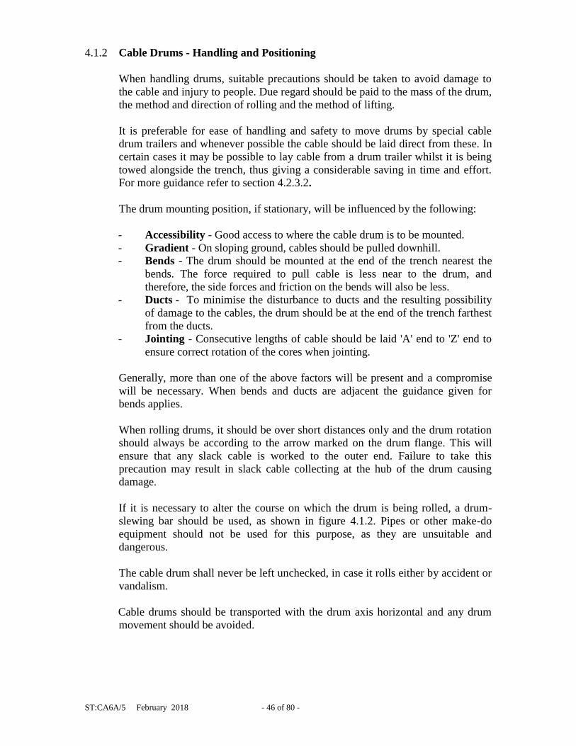
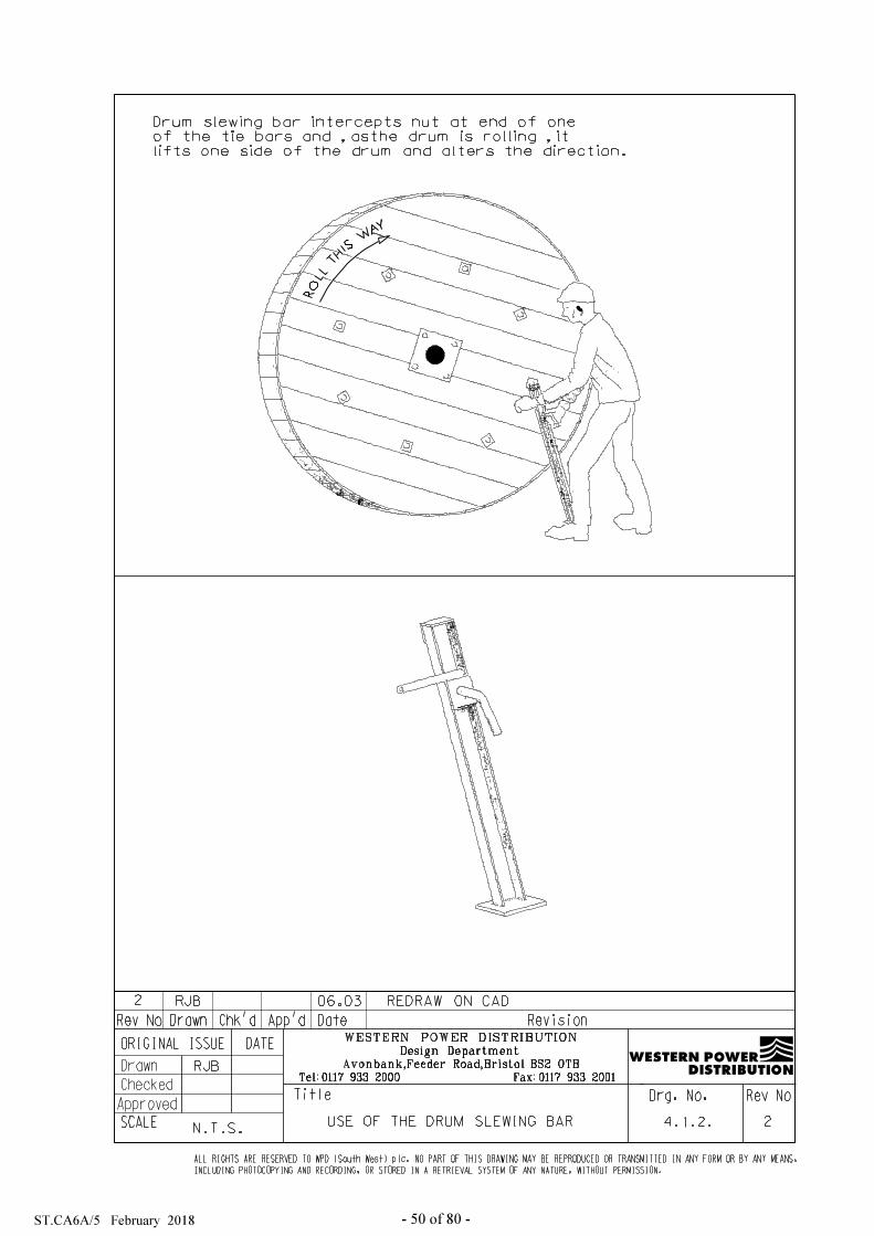
If it is necessary to alter the course on which the drum is being rolled, a drum-
slewing bar should be used, as shown in figure 4.1.2. Pipes or other make-do
equipment should not be used for this purpose, as they are unsuitable and
dangerous.
The cable drum shall never be left unchecked, in case it rolls either by accident or
vandalism.
Cable drums should be transported with the drum axis horizontal and any drum
movement should be avoided.

ST:CA6A/5 February 2018 - 47 of 80 -
The cable drum must be so arranged that the cable be pulled off the top of the
drum. If battens are fitted and the end of the cable cannot be seen, the drum
should be set up so that it will rotate during cable laying in the opposite direction
to the 'rolling' arrow.
Cable ends should be firmly attached to the drum during transport and storage to
prevent damage to the cable.
Care should be taken to avoid damage to the cables caused by nails or staples
used in drum manufacture or when applying battens.
For loading and unloading of cable drums, suitable lifting and hoisting equipment
should be used. A drum should not be dropped.
4.1.3 Winch Positioning
Normally, the cable will be pulled direct from the drum trailer but in its absence,
drum jacks and spindles should be used. A 2.1m long by 75mm outside diameter
5000kg SWL high tensile seamless steel tubular drum spindle with 2 x 5000kg
ratchet type cable drum jacks with timber bases and cups to take up to 100mm
spindles will support cable drums holding up to 250m of the largest standard sizes
of LV, HV and EHV cables.

ST:CA6A/5 February 2018 - 48 of 80 -
Cable drum jacks should be mounted on a firm level base. If the ground is
uneven, a foundation should be provided by using stout timber solidly packed.
Timber packing may also be necessary to prevent settling of the jacks by
spreading the weight if the ground is soft. It may be necessary to locate the drum
in the roadway away from the trench and in this case the drum should then be
offset by not more than 30 degrees to the line of the trench. For safety, the drum
should not be mounted closer than 1m to trench excavations of normal depth.
The drum should be raised to just clear the ground and the drum spindle levelled
to prevent the drum moving to one end. The level of the drum should be checked
by a plumb bob against the drum side or by placing a spirit level on the drum
spindle. When using a spirit level with heavy cable drums, readings should be
taken at each end to compensate for deflection of the loaded spindle.
The spindle should be greased and a check made for smooth rotation of the drum.
Drum battens and steel bands if fitted may then be removed. For safety, all nails
should be withdrawn from the battens and drum rim immediately and the battens
stacked neatly.
The winch to be used may be of the platform mounted, trailer mounted, or vehicle
mounted type.
The winch should be positioned at the end of the cable trench and securely
anchored. It is important to note that where a boom is used, the main anchorage
against the pull must be at the lower end of the boom. The anchorage should be
obtained by cross bracings recessed into the sides of the trench.
4.1.4 Cable Bedding
The bed of the cable trench shall be free from water, stones, and pieces of rock
that may cause damage to the cable. Loose stones in the trench sides that may be
dislodged during the cable pull, shall be removed.
Crushed limestone dust 3mm to dust, or crushed granite, 3mm to dust, shall be
imported and should be laid to provide a suitable bedding for the cable or duct.
Once the cable or duct has been laid onto the bedding a further layer of crushed
limestone dust or crushed granite dust shall be applied, this shall be for a depth of
75mm above the cable or duct.
4.1.5 Cable Rollers - Positioning
The rollers are necessary to avoid abrasion of the cable by keeping it clear of the
ground and to reduce friction during pulling. The types of roller generally
available are depicted in figure 4.1.5a. The ramps built into the straight and
corner cable rollers allow the cable end to ride over without being lifted. These
rollers are, therefore, suitable for either winch or hand pulling. The arrangement
of cable rollers will depend upon which of these methods is used.

ST:CA6A/5 February 2018 - 49 of 80 -
A typical arrangement of rollers in a trench is shown in figure 4.1.5b.
The straight rollers should be no more than 2m apart. Too great a spacing between
rollers will allow excessive sag in the cable and 'rowing' will result whenever the
pull is released and then taken up again. This is particularly wasteful of effort
during hand pulling. Special attention should be paid to the position of rollers in
the trench at points where a change of direction is made.
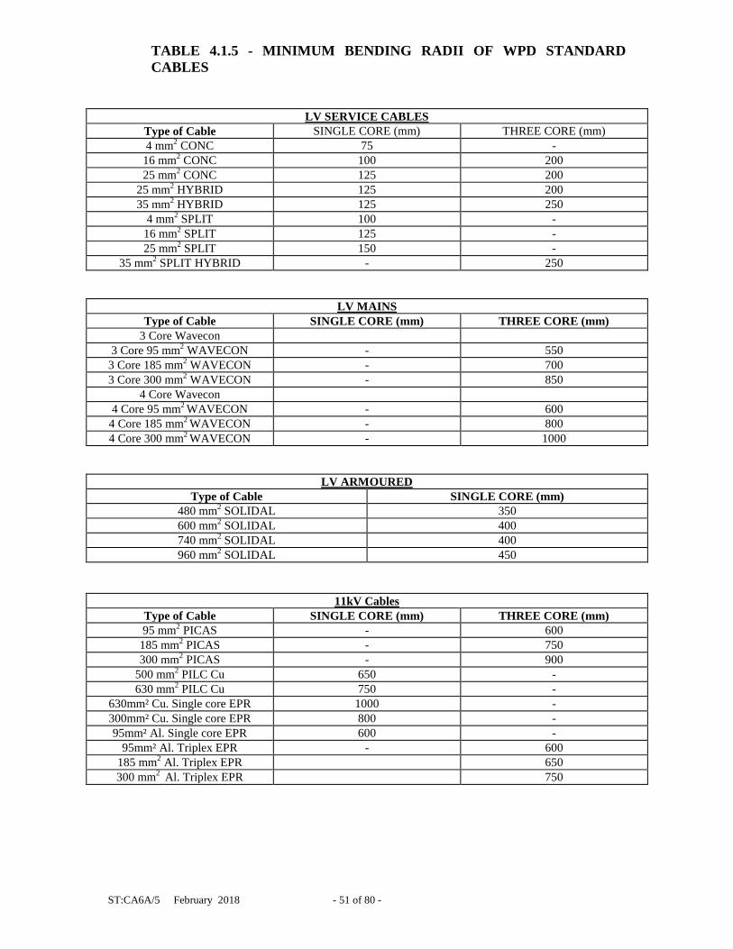
The positioning of the rollers should be such that the cable is not bent around too
sharp a radius. Refer to table 4.1.5 for details of minimum bending radius for
cables.
ST:CA6A/5 February 2018 - 51 of 80 -
TABLE 4.1.5 - MINIMUM BENDING RADII OF WPD STANDARD
CABLES
LV SERVICE CABLES
Type of Cable SINGLE CORE (mm) THREE CORE (mm)
4 mm2 CONC 75 -
16 mm2 CONC 100 200
25 mm2 CONC 125 200
25 mm2 HYBRID 125 200
35 mm2 HYBRID 125 250
4 mm2 SPLIT 100 -
16 mm2 SPLIT 125 -
25 mm2 SPLIT 150 -
35 mm2 SPLIT HYBRID - 250
LV MAINS
Type of Cable SINGLE CORE (mm) THREE CORE (mm)
3 Core Wavecon
3 Core 95 mm2 WAVECON - 550
3 Core 185 mm2 WAVECON - 700
3 Core 300 mm2 WAVECON - 850
4 Core Wavecon
4 Core 95 mm2 WAVECON - 600
4 Core 185 mm2 WAVECON - 800
4 Core 300 mm2 WAVECON - 1000
LV ARMOURED
Type of Cable SINGLE CORE (mm)
480 mm2 SOLIDAL 350
600 mm2 SOLIDAL 400
740 mm2 SOLIDAL 400
960 mm2 SOLIDAL 450
11kV Cables
Type of Cable SINGLE CORE (mm) THREE CORE (mm)
95 mm2 PICAS - 600
185 mm2 PICAS - 750
300 mm2 PICAS - 900
500 mm2 PILC Cu 650 -
630 mm2 PILC Cu 750 -
630mm² Cu. Single core EPR 1000 -
300mm² Cu. Single core EPR 800 -
95mm² Al. Single core EPR 600 -
95mm² Al. Triplex EPR - 600
185 mm2 Al. Triplex EPR 650
300 mm2 Al. Triplex EPR 750
ST:CA6A/5 February 2018 - 52 of 80 -
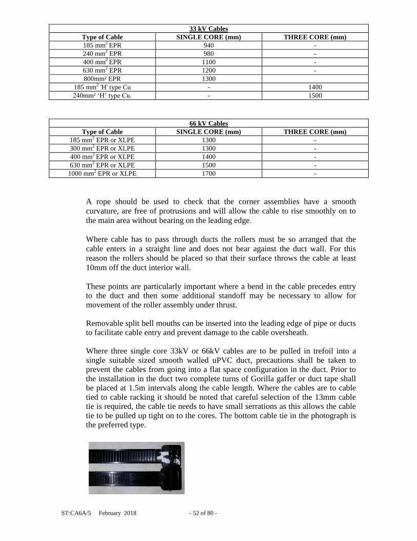
33 kV Cables
Type of Cable SINGLE CORE (mm) THREE CORE (mm)
185 mm2 EPR 940 -
240 mm2 EPR 980 -
400 mm2 EPR 1100 -
630 mm2 EPR 1200 -
800mm² EPR 1300
185 mm2 'H' type Cu - 1400
240mm² ‘H’ type Cu. - 1500
66 kV Cables
Type of Cable SINGLE CORE (mm) THREE CORE (mm)
185 mm2 EPR or XLPE 1300 -
300 mm2 EPR or XLPE 1300 -
400 mm2 EPR or XLPE 1400 -
630 mm2 EPR or XLPE 1500 -
1000 mm2 EPR or XLPE 1700 -
A rope should be used to check that the corner assemblies have a smooth
curvature, are free of protrusions and will allow the cable to rise smoothly on to
the main area without bearing on the leading edge.
Where cable has to pass through ducts the rollers must be so arranged that the
cable enters in a straight line and does not bear against the duct wall. For this
reason the rollers should be placed so that their surface throws the cable at least
10mm off the duct interior wall.
These points are particularly important where a bend in the cable precedes entry to the duct and then some additional standoff may be necessary to allow for movement of the roller assembly under thrust.
Removable split bell mouths can be inserted into the leading edge of pipe or ducts to facilitate cable entry and prevent damage to the cable oversheath. Where three single core 33kV or 66kV cables are to be pulled in trefoil into a single suitable sized smooth walled uPVC duct, precautions shall be taken to prevent the cables from going into a flat space configuration in the duct. Prior to the installation in the duct two complete turns of Gorilla gaffer or duct tape shall be placed at 1.5m intervals along the cable length. Where the cables are to cable tied to cable racking it should be noted that careful selection of the 13mm cable tie is required, the cable tie needs to have small serrations as this allows the cable tie to be pulled up tight on to the cores. The bottom cable tie in the photograph is the preferred type.
ST:CA6A/5 February 2018 - 53 of 80 -
4.1.5.1 Winch Pulling
Dynamometers should be fitted to all winches so as the maximum pulling tension of the cables is not exceeded on installation. A digital print out should also be obtained at the end of each completed cable pull to prove the cable was not over tensioned during installation. If the cable pull appears to be difficult it is advisable to use a caterpillar cable pusher, which is installed at the start of the cable run. This caterpillar is used in conjunction with the winch, when used in this fashion this will greatly reduce pulling tensions on the cable. The winch cable will always take a direct line between angle positions and may also tend to lift up or bear down hard according to the contour of the trench. The position and level of the rollers must, therefore, be carefully arranged to prevent the taut winch rope, or cable damaging or being damaged by pipes crossing the trench. An inverted skid plate attached to screw jacks wedged across the trench will guide the cable and winch rope under obstructions.
To facilitate the pulling of cables around bends in the trench, curved steel plates or special curved corner roller assemblies should be set up against the wall of the trench to minimise the additional strain due to change of direction. To counteract sideways thrust, packing should be used to stabilise the corner assemblies.
Crowbars or single rollers should not be used on their sides at bends as they can cause flattening or bird caging of the triplex cable during installation.
Where pulling is difficult lubrication will ease cables round bends and through
ducts. For safety, the lubricant must be applied by stick or brush and not by hand. A mixture of common household powdered detergent and powdered graphite mixed in equal proportions with water to form a paste is recommended for this, as it is 'non-sticky' and loose stones are unlikely to adhere to the cable.
Grease should not be used as the lubricant as grit will adhere to it. When two cables are to be laid side by side, a double line of rollers should be
placed in the trench at bends and duct entrance positions so that the second cable can be pulled as soon as the first cable has been taken off the straight line rollers and while the men are still in position.
4.1.5.2 Hand Pulling Cable rollers should be arranged as for winch pulling but some relaxation of the
measures to counter thrusts at corners may be possible. On straight sections of the trench the rollers should be placed centrally to allow a man to stand astride the cable when pulling.
4.2 Cable Pulling
Cable should always be pulled to provide a 1.2m overlap for jointing purposes.
Where cable is cut to length the end must be sealed to prevent moisture ingress.

ST:CA6A/5 February 2018 - 54 of 80 -
4.2.1 Cable Attachments
When using Triplex cable it helps to prevent the unwinding of the cable if 13mm
wide cable ties (E 5 No. 35370) are placed on the leading 5m to 7m of cable, prior
to the cable being laid. If this cable is then to be pulled into ducts the cable ties
should be taped over with Scotch 88 tape to prevent the cable ties snagging on the
ducts. All short lengths of triplex should be cable tied to prevent the cable
unwinding, prior to the laying of the short length of cable.
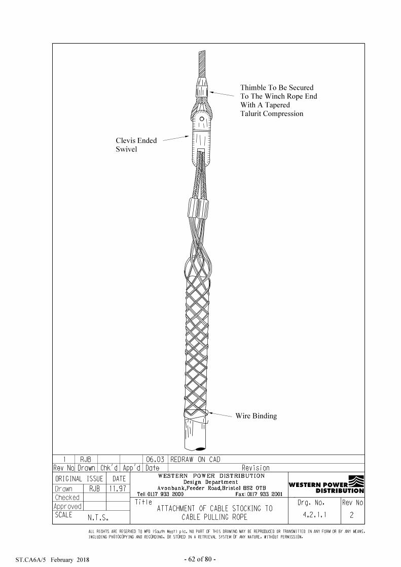
4.2.1.1 Attachment of Cable Stocking to Cable
The approved method of attachment of the cable pulling rope to the cable is by
cable stocking or three in one swivel head. There are wide ranges of sizes
available from many different manufacturers. The stockings distribute the pull
and avoid damage; care must be taken to ensure that the stocking fits over the
oversheath of the cable. In the case of Triplex cable individual stockings should
be applied to all three cores and these in turn should be attaches to the swivel on
the pulling bond. In all cases the stocking should be pushed fully on to the cable
and should be secured at the end with binding wire as shown in figure 4.2.1.1.
The cable stocking will also have a SWL equivalent to the maximum pulling
tension of the cable. After the end of the cable has been freed from the drum the
cable stocking should be fitted.
Table 4.2.1 gives guidance on maximum pulling tensions and diameters of cables
most commonly used in WPD.

ST:CA6A/5 February 2018 - 55 of 80 -
TABLE 4.2.1 - MAXIMUM STOCKING PULLING TENSIONS & OVERALL
DIAMETERS
Cable voltage Cable type Nominal overall diameter
(mm)
Pulling tension safe limit
(N)
66kV 185 mm2 EPR 54 6185N
66kV 300 mm2 EPR 57 6300N
66kV 400 mm2 EPR 60 6400N
66kV 630 mm2 EPR 65 6630N
66kV 1000 mm2 EPR 76 61000N
33kV 185 mm2 EPR 47 6627N
33kV 300 mm2 EPR 49 7203N
33kV 400 mm2 EPR 55 9075N
33kV 630 mm2 EPR 60 10800N
33kV 800mm² EPR 65 12675N
33kV 240mm²’H’ type Cu. 75 16875N
33kV 185 mm2 'H' type Cu 70 14700N
11kV 95 mm2 PICAS 50 6800N
11kV 185 mm2 PICAS 61 11163N
11kV 300 mm2 PICAS 73 15987N
11kV 400 mm2 PICAS Cu. 81 19683N
11kV 500 mm2 PILC 43 5547N
11kV 630 mm2 PILC 47 6627N
11kV 630 mm2 EPR 48 6912N
11kV 95 mm2 EPR Triplex 28 2352N
11kV 185 mm2 EPR Triplex 33 3267N
11kV 300 mm2 EPR Triplex 37 4107N
LV 3 Core 95 mm2 WCON 35 3675N
LV 3 Core 185 mm2 WCON 46 6348N
LV 3 Core 300 mm2 WCON 55 9075
LV 4 Core 95 mm2 WCON 40 4800N
LV 4 Core 185 mm2 WCON 54 8748N
LV 4 Core 300 mm2 WCON 64 12288N


ST:CA6A/5 February 2018 - 59 of 80 -
4.2.1.2 Attachment of Pulling Rope to Cable Stocking
When pulling by winch, a clevis-ended swivel must be fitted between the rope
and the thimble of the cable stocking. The swivel, as shown in figure 4.2.1.1, is
streamlined and complete with clevis fittings for rope and stocking. It shall also
have a SWL, which will at least match the maximum pulling tension associated
with the cable to be installed.
The swivel allows the rope to turn freely. Without a swivel a twisting strain will
result under load, and should there be a sudden release of this, the whip-back on a
steel rope will be dangerous and in many cases cause kinking.
4.2.2 Rope Bonds
The preferred rope bond used is steel wire rope, but this is not suitable for hand
pulling as it is springy, too small in diameter to grip, and broken strands may lead
to injury.
When pulling by hand, either natural or synthetic fibre rope may be used but care
must be taken to ensure the SWL of the rope is not a limitation when pulling
cables to the recommended maximum tensions.
4.2.2.1 Steel Wire Rope
For winches, steel wire rope is preferred to fibre rope as its smaller size allows a
compact arrangement of winch and take up spool, and there is little deterioration
if the rope is properly maintained. Gloves must always be worn when handling
wire ropes.
Tapered Talurit compressed ferrules should be specified for the thimble end to
avoid a shoulder that could catch up on ducts or rollers.
To prevent the possibility of kinking and disturbance of the lay, ropes should be
paid out without slack and in a straight line.
After use and before storage, the wire rope should be wire brushed, examined and
lubricated with wire rope dressing.
4.2.3 Methods
Winch pulling or the laying of cable direct from a moving cable drum trailer is to
be preferred to hand pulling purely because it is less arduous and fewer people are
required.
Nevertheless for short lengths of cable, hand pulling may be expedient.
Whichever method is used all men should wear protective gloves and footwear
throughout the pulling/handling operations.
ST:CA6A/5 February 2018 - 60 of 80 -
4.2.3.1 Winch Pulling
The winch operating procedures outlined in these sections are suitable for most
types of winch at present available, although some variation in procedure may be
required for a particular type of winch.
Winches should be fitted with a digital dynamometer arrangement to ensure the
maximum pulling tension of the cable being installed is not exceeded. A print of
the pulling tensions should be provided at the end of each completed cable pull.
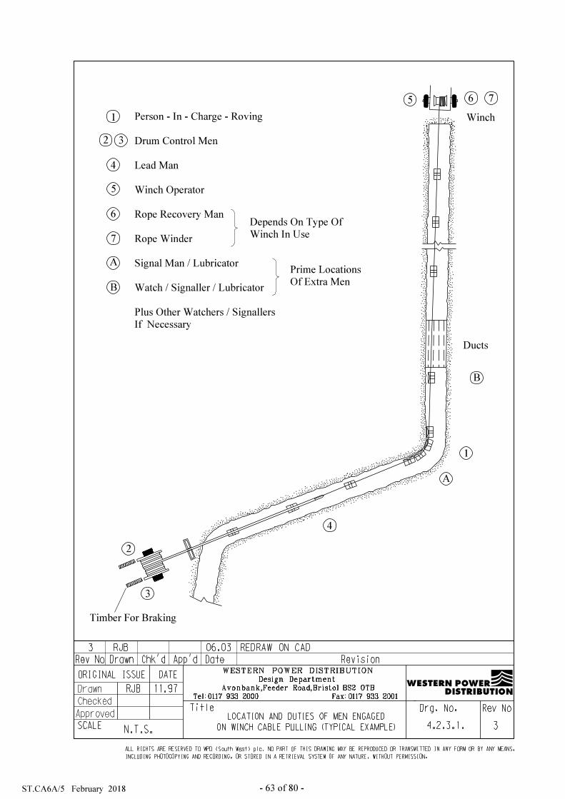
The number of men required is dependant on the winch type and size, and the
nature of the job. Figure 4.2.3.1 depicts a typical example of the location and duties of men on
winch cable pulling.
The person-in-charge should ensure that all personnel employed on cable winching are familiar with the signalling procedures employed. Each signal should be positive and distinct.
Portable radio may be helpful on schemes where hand signals cannot easily be used.
At any time, any man in the team is at liberty to give the emergency stop signal
should personal danger or serious circumstances arise. 4.2.3.2 Laying Cable from a Moving Drum Trailer Laying the cable directly into or beside the trench from a drum trailer whilst it is
being towed along slowly can make considerable saving in time and effort. This method can only be used if there is unobstructed access beside the trench and if there were no pipes or services crossing the trench under which the cable would have to be laid. It is ideally suited to coordinated mains laying in a common trench.
When laying direct into a trench, the end of the cable should be fed off the drum
and laid in position in the trench. The drum trailer should then be towed slowly alongside the trench. Three or four men must initially hold back the cable and then progressively ease it over the edge and onto the trench bed.
If the trench edge is not firm enough to allow a vehicle to be driven reasonably
close to it, the cable can be fed from the drum trailer on to the ground beside the trench. The cable end is pulled from the trailer and placed in its final position in the trench. The remainder of the cable is then laid from the moving drum trailer directly on to the ground beside the trench. Subsequently the cable is manhandled on to the trench bed, starting from the point where the end of the cable is already in the trench. This method is not recommended for 33kV cable or the larger sizes of 11kV EPR cable, i.e. 300mm² single core EPR and 630mm² single core EPR, as it is heavier, and stiffer to control and bend.

ST:CA6A/5 February 2018 - 61 of 80 -
4.2.3.3 Pulling in by Hand
When it is necessary to pull in by hand, the men should be spaced clear of each
other along the pulling rope. As the cable is pulled into the trench the men should
move back from the rope on to the cable.
To avoid dangers from trapping, men should not be positioned on corners, or on
the drum side of the cable rollers for pulling cable. The cable itself should be
handled with cable slings thereby avoiding the possibility pinching fingers
between cable rollers and the cable, and enabling men to pull with a straight back.
Care should be taken at bends to congregate men on the approach side so as to
relieve friction on the bend.
The supervisor should ensure good control of the cable and unified pulling efforts
either by using a whistle or other means with which the staff are familiar.
Similarly, cessation of pull should follow a clear signal.
It must also be seen to that any undue slack does not accumulate on the drum, by
employing somebody to apply braking, via the drum flanges, when necessary.
Where a cable is drawn through a road-crossing duct, pulling in should be stopped
when the cable end is near the duct mouth and the pulling in rope attached to a
pilot rope or wire, which has been previously drawn into the duct. The cable end
should then be eased into the duct mouth and pulling continued.
4.2.3.4 Bond Pulling
The general principle of bond pulling is as shown in figure 4.2.3.4.
A steel wire bond, which shall be at least twice the cable section length, is run out
through the whole length of the trench over cable rollers positioned in the trench
in the line, which the cable is to follow.
The cable shall be tied to the bond at no greater than 2m intervals along its entire
length. Where large diameter cables are to be installed, or the cables are to be
installed on a steep incline or down a shaft, the number of ties is to be increased.
At each change of direction the ties shall be released and the cable taken round
the bend using a series of vertical skid plates and horizontal rollers, the bond wire
passing through a snatch block. The cable shall be re-attached to the bond
immediately after the change of direction. The nose of the cable shall be guided
over the corner rollers ensuring that a positive tension is maintained on the nose
of the cable to prevent the build up a slack at the bend.

ST:CA6A/5 February 2018 - 64 of 80 -
Although this procedure is rather labour intensive, it has the overwhelming
advantage that there is no tension applied to the nose of the cable as it is
distributed along the length and the risk of stretching one or more of the cable
components is minimal.
4.2.4 Flaking and Coiling Cable
As it is not always possible to lay the complete length of cable directly into the
trench due to obstructions, limited choice of drum mounting position, or the need
to excavate and backfill part of the trench quickly and as a result it may be
necessary to coil the remainder of the cable or flake it off the drum.
At all stages of these operations, care must be taken not to twist the cable or bend
it too sharply.
In the coiling method, few men are required as the cable has already been pulled
off the drum and the coils have merely to be handled individually into position,
where they require little space.
The flaking method requires more labour as the cable has to be pulled off the
drum and handled in figures of eight which are larger than coils and require more
space.
4.2.4.1 Coiling Cable Where the whole of the required cable can be taken off the drum in the initial pull
but only part of this is laid directly in the trench, the surplus can be coiled to a suitable position in the manner shown in figure 4.2.4 a. The cable should be subsequently rolled out by a similar method. The coil diameter should not fall below the minimum-bending radius of the cable.
4.2.4.2 Flaking Cable Where all the required cable cannot be taken from the drum during the initial pull
(i.e. if the drum has to be mounted part way along the cable route) the cable can then be laid in the trench up to the drum position and the remainder then flaked off the drum and laid on the ground in the form of a figure of eight as shown in figure 4.2.4 b.
4.2.5 Pulling Single Core 66kV, 33kV EPR and Single Core 11kV EPR Cable The single cores should be laid in trefoil in trenches with dimensions as detailed
in table 3.2 and figure 3.2b. It is important that the trench is sufficiently wide to accommodate operatives who
should tie the three cores together at 1.5m intervals with 13mm wide plastic cable ties E 5 No 35370 (1m at bends). When installing three single core cables, the method to be adopted depends on site conditions. In most cases it may prove easier to pull each of the cores out individually and then tie them together in the trench. If the cables are to be laid in a green-field site, it may prove preferable to pull the three cores simultaneously from three drums and then tie them together as they enter the trench.

ST:CA6A/5 February 2018 - 65 of 80 -
When installing any voltage level of three single cores cables into a single duct
then all three cores shall be pulled together and every two metres two complete
turns of Gorilla duct tape E 5 number 60928 shall be applied to the cables prior to
entering the ducts, thus keeping the cables in trefoil.
4.3 Cleating
When it is necessary to install metal-sheathed cables on supports, the spacing of
these is an important factor.
Single core cables are to be cleated every 1.5m using Ellis patent cleats with an
Ellis patent strap in between every cleat.
The thermal expansion of 3 core cables is approximately 100mm in 250m over
the normal operating temperature range. Cleats if erected too closely together may
produce sheath fractures over a period due to localised flexing caused by
expansion and contraction with change in temperature.
Hooks or cleats should provide an axial length of support of not less than 0.6
times the diameter of the cable and the corners should be radiused 5mm to prevent
sharp indentations or damage to the cable.
4.3.1 Horizontal Straight Runs
Cables should be installed with sag in order to reduce the amount of flexing of the
sheath and 2% of the recommended span is suitable.
Norma lly, sagging should be carried out on each span about 2 spans behind the
last support in which the cable has been laid. It may be necessary to hold down
each span while the next one is sagged and a straight edge with a projection at the
middle equal to the required sag will be useful.
Supports, which grip the cable, are required only where a tendency to move has to
be restrained, such as joints, vertical runs, or slopes.
4.3.2 Horizontal Bends
Spacing of cleats on horizontal bends should be similar to that on straight
horizontal runs. If the distance between cleats is increased, horizontal supports
should be provided on the bends to allow lateral movement of the cable during
expansion.

ST:CA6A/5 February 2018 - 67 of 80 -
4.3.3 Cable Runs other than Horizontal and Straight
When it is necessary to install metal-sheathed cables on supports, the spacing of
these is an important factor.
Single core cables laid in touching trefoil are to be cleated every 1.5m using Ellis
patent Atlas two bolt cleats with an Ellis patent strap in between every cleat.
The thermal expansion of 3 core cables is approximately 100mm in 250m over
the normal operating temperature range. Cleats if erected too closely together may
produce sheath fractures over a period due to localised flexing caused by
expansion and contraction with change in temperature.
Hooks or cleats should provide an axial length of support of not less than 0.6
times the diameter of the cable and the corners should be radiused 5mm to prevent
sharp indentations or damage to the cable.
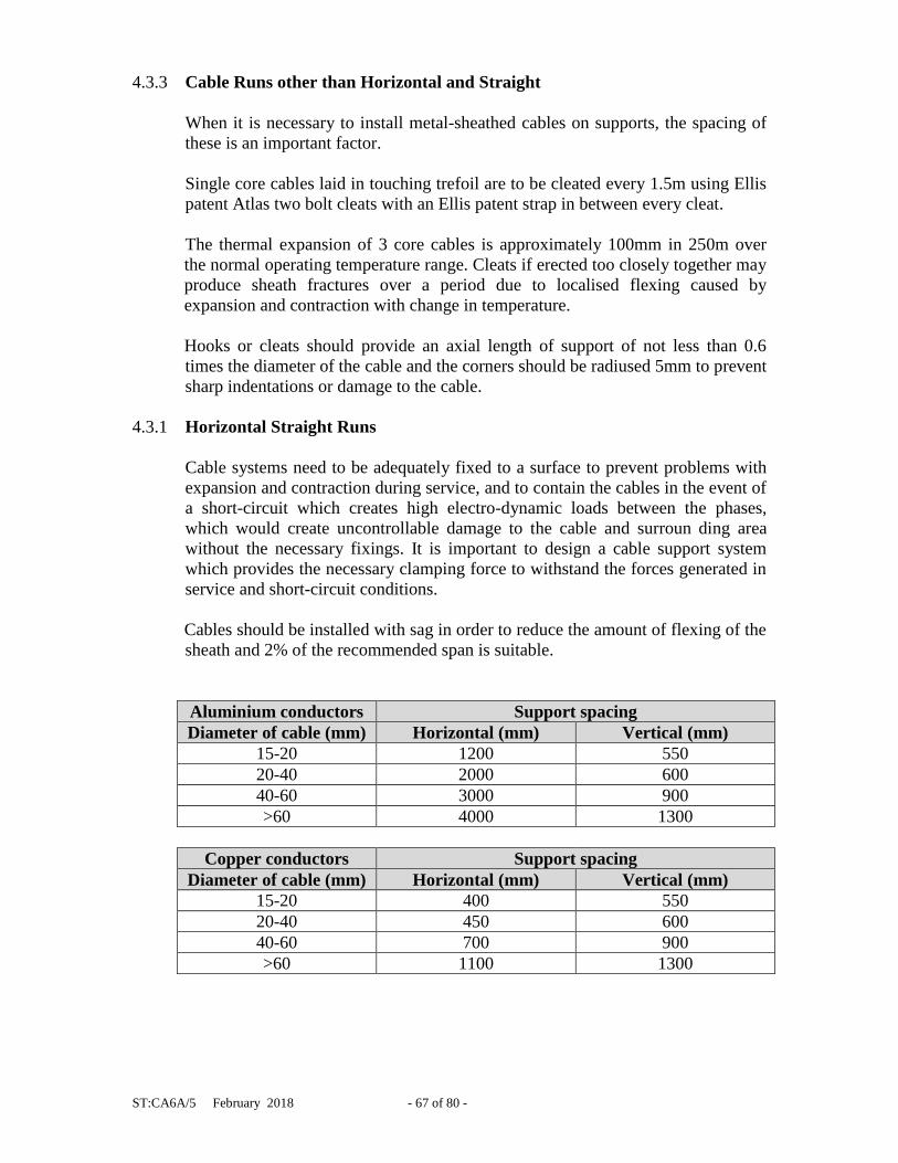
4.3.1 Horizontal Straight Runs
Cable systems need to be adequately fixed to a surface to prevent problems with
expansion and contraction during service, and to contain the cables in the event of
a short-circuit which creates high electro-dynamic loads between the phases,
which would create uncontrollable damage to the cable and surroun ding area
without the necessary fixings. It is important to design a cable support system
which provides the necessary clamping force to withstand the forces generated in
service and short-circuit conditions.
Cables should be installed with sag in order to reduce the amount of flexing of the
sheath and 2% of the recommended span is suitable.
Aluminium conductors Support spacing
Diameter of cable (mm) Horizontal (mm) Vertical (mm)
15-20 1200 550
20-40 2000 600
40-60 3000 900
>60 4000 1300
Copper conductors Support spacing
Diameter of cable (mm) Horizontal (mm) Vertical (mm)
15-20 400 550
20-40 450 600
40-60 700 900
>60 1100 1300

ST:CA6A/5 February 2018 - 68 of 80 -
Normally, sagging should be carried out on each span about 2 spans behind the
last support in which the cable has been laid. It may be necessary to hold down
each span while the next one is sagged and a straight edge with a projection at the
middle equal to the required sag will be useful.
Supports, which grip the cable, are required only where a tendency to move has to
be restrained, such as joints, vertical runs, or slopes. In this instance Ellis Patent
Atlas two bolt cable cleats shall be used.
4.3.2 Horizontal Bends
Spacing of cleats on horizontal bends should be similar to that on straight
horizontal runs. If the distance between cleats is increased, horizontal supports
should be provided on the bends to allow lateral movement of the cable during
expansion.
4.3.3 Cable Runs other than Horizontal and Straight
On bends, which are sloping or vertical, the cables should be cleated no more
frequently than is required for stable positioning.
For vertical or steeply sloping (> 60 deg from the horizontal) lengthy straight
runs, the cable should be snaked by bowing in opposite directions alternatively
between successive cleats.
A deflection of 5% of cleat spacing is suitable. For this the cleat should be at an
angle of about 6 degrees to the line of run and a single bolt fixing is convenient to
enable each cleat to set itself to the cable. Cleating should be carried out from the
bottom, with the cable eased off from the top as required. The greater the spacing
of the cleats compatible with mechanical strength, the easier will be the setting of
the cable.
4.4 Cable End Capping
The capping of cable ends, once the cable has been laid, is very important to
prevent the ingress of moisture. With the more modern insulating materials such
as PVC, XLPE etc. the need to prevent moisture ingress is to allow the LDPu
resin to seal effectively, prevent corrosion of aluminium conductors as well as the
requirement for electrical safety when working on these cables.
There are three preferred methods of capping cables: -
(a) Cold shrink cap
(b) Heat shrink cap
(c) Denso seal
ST:CA6A/5 February 2018 - 69 of 80 -
4.4.1 Cold Shrink Cap
The most commonly used, can be applied to all cable types. Before preparing and
applying, a cap of the correct size must be selected, caps are range taking to suit
variable cable diameters and to ensure a good moisture seal the selection is most
important.
Methods of Application
PVC Oversheath Cables
1. Select correct cap to suit cable diameter, ensure the cap is coated
internally with sealant and not pin-holed.
2. Clean and degrease PVC oversheath.
3. Slide the cap onto the cable pushing well onto the cable end.
4. Pull the spiral out of the cold shrink cap in an anti-clockwise direction
until the cold shrink cap is fully shrunk onto the cable.
4.4.2 Heat Shrink Cap
This is the most widely used method as it can be applied without any specific
skills. Before preparing and applying a heat shrink cap, the correct size must be
selected, as these caps are range taking to suit variable cable diameters.
In order to seal PVC oversheath cables such as service cable, WAVECON, or
PICAS, the following steps should be followed:
(1) Select correct size for cable diameter.
(2) Clean PVC oversheath with approved cleaner.
(3) Abrade PVC oversheath for the length of the cap using a rasp on large
diameter cables or emery cloth for service cables. Ensure the abrading is
undertaken circumferentially and all glossing if the sheath is removed.
(4) Clean abraded area with approved cleaner.
(5) Slide cap onto cable, pushing onto cable end.
(6) Using a soft blue flame, start shrinking from the closed end of the cap and
work towards the open end. Ensure the flame is worked evenly around the
cap and enough heat is given to melt the sealant, but not to burn the
material. Once the cap is fully shrunk down, a ring of sealant will be seen
at the open end of the cap.
ST:CA6A/5 February 2018 - 70 of 80 -
In order to seal PILCSTA or PILCSWA, either a heat shrink cap or a plumbed cap
can be used. If a heat shrink cap is to be used, the following steps should be
carried out:
(1) Mark outer serving the length of the cap plus 50mm from the cable end,
apply a wire or PVC tape binder at this point.
(2) Remove outer serving.
(3) Using a depth gauge, hacksaw cut around the armour at the binder.
(4) Remove armour and underlying bedding.
(5) Apply heat and remove bitumen impregnated paper, thoroughly clean lead
sheath and allow to cool.
(6) Clean lead sheath with approved cleaner.


ST:CA6A/5 February 2018 - 73 of 80 -
(7) Abrade the circumference of the lead sheath the full length of the cap,
using a file.
(8) Clean abraded area with approved cleaner.
(9) Ensure all sharp edges are removed from the cable end.
(10) Complete using steps 5 and 6 as for PVC oversheathed cables.
In order to seal Single core XLPE, Single core EPR or Triplex EPR, a heat shrink
cap shall be used and the following procedure applied: -
(1) Select correct size for cable diameter.
(2) Clean oversheath with approved cleaner.
(3) Abrade sheath for the length of the cap using a rasp on large diameter
cables or emery cloth for service cables, whilst ensuring the abrading is
undertaken circumferentially.
(4) Clean abraded area with approved cleaner.
(5) Using a very soft blue flame, gently heat up the abraded area until it
appears to slightly change colour.
(6) Complete using steps 5 and 6 as for PVC oversheathed cables.
4.4.3 Denso Tape Seals
As a temporary measure Denso tape seals may be applied to each individual cable
core end to affect a moisture seal.
5.0 REINSTATEMENT
5.1 Backfill to Marker Tape
Particular care is required when laying unarmoured cables in order to ensure that
no objects can cause a pressure point on the cable sheath. It may be necessary to
pad the sharp edged ends of earthenware ducts if there is any likelihood of cable
settlement.
Crushed limestone dust, 3mm to dust, or crushed granite dust, 3mm to dust, must
be used when bedding and blinding cables. The depth of crushed stone dust
bedding will depend on the cross sectional area or physical size of the cable being
laid; this should be compacted prior to laying the cable. The blinding should be
laid in a single operation after the cable has been lifted off the cable rollers.
Cables shall be blinded by 75mm of imported crushed stone dust before warning
marker tape be laid above the run of the cable. Should site conditions warrant the
use of protective equipment such as the 'Stokboard', the blinding of crushed
limestone or granite dust, shall still be 75mm.

ST:CA6A/5 February 2018 - 74 of 80 -
5.2 Re-use of Excavated Material
Temporary spoil and material heaps should be sited to interfere as little as
possible with the work to be carried out. Whilst, for convenience in handling, it
might be necessary to place them near excavations, the following points should be
borne in mind: -
a) They should not interfere with free access to the excavation.
b) They should be so constructed that there is no danger of the spoil
slumping in wet weather and entering the excavation.
c) Spoil heaps should not be placed in such a position as to endanger the
stability of existing works above or below ground or of the excavation, the
sides or side supports of which should be so designed as to be capable of
withstanding the additional stresses due to any superimposed load.
Spoil heaps should be graded to safe slopes taking into account the nature of the
material and the effects of wet weather, the material should remain substantially
unaltered in wet weather, but with materials that soften and slump a substantial
reduction in the slope should be anticipated and a adequate distance maintained
between the spoil heap and the edge of the excavation.
The clearance between the toe of the spoil heap and the edge of the excavation
should give sufficient working space at all times, and for this purpose the
clearance should be a distance equal to the depth of the excavation with a
minimum width of 1.50m
The following materials are categorised as unacceptable for reuse: -
- Peat and materials from swamps, marshes, or bogs.
- Logs, stumps, and perishable materials.
- Materials in a frozen condition.
- Liquid clays.
- Materials subject to spontaneous combustion.
- Materials having hazardous chemical or physical properties.
5.3 Compacting
Special care should be taken not to damage the cable during consolidation and
only hand rammers should be used within 150mm of the cable. When mechanical
rammers are used, there should be enough material placed in the trench so that it
can be compacted to a 150mm layer, particular care must be taken if the
'thumping' type rammer is used.
ST:CA6A/5 February 2018 - 75 of 80 -
5.4 Reinstatement above Marker Tape
The reinstatement, whether it is 'permanent' or ’interim’, should meet the
requirements as set out in the Department for Transport Specification for the
Reinstatement of Openings in Highways April 2010. This also applies reinstating
verges adjacent to highways.
For the reinstatement of open ground, it is usually adequate to compact the ground
from the surface. The ground should be left 'proud' to allow for subsequent
settlement. If turf has to be re-laid, it should be watered thoroughly during dry
weather.
6.0 PRIOR TO ENERGIZATION OF THE ALL CABLE CIRCUITS
In compliance with the ESQC Regulations 2003 no cable circuit shall be
energized unless the following minimum conditions have been meet: -
On building sites where cable has been laid, and/or additional cable will be
required to be laid in the near future then the minimum, which will be acceptable
prior to the cable, being energized, is the cables are covered with 75mm of
crushed limestone or granite dust, 3mm to dust, and marker tape laid on top of the
crushed limestone or granite dust, as per ST: NC2H – Relating to Inspection and
Recording.
Where joint holes have been dug and exposed the cables the minimum
requirement shall be that the joint hole shall signed and guarded as per ST:
HA14D.
Where the cable has been laid up to a pole, the minimum requirement shall be that
the cable and pole shall signed and guarded as per ST: HS14D.

ST:CA6A/5 February 2018 - 76 of 80 -
APPENDIX A
A.3.3.1 Impact Measurement
For double circuit 132kV circuits running in the same trench then the impact assessment
shall take into account three specific parameters: -
1) Number of customers affected, this is the number of customers that will
experience supply loss if both circuits were hit simultaneously with e.g. an HDD
or by a digger or some other common mode failure.
2) Time to restore supplies; this is the time to restore supplies to customers, taking
account of the circumstances, conditions and environment when the event occurs.
In practice restoration of supplies maybe through more than one stage.
3) Having double 132kV circuits in a single trench will increase the impact/risk of
other shut downs or outages where the load will be flowing in these two
underground circuits because then there is a heightened impact/risk if these
circuits are then hit during the shutdown or outage of adjacent circuits. This will
need to be considered when undertaking shutdowns or programming outages.
In assigning likelihood and impact, it is important to decide whether the impact should be
on the basis of: -
The worst that could happen (the realistic upper bound) or
The most likely outcome (the most probable outcome taking into account of
typical circumstances).
The basis of both likelihood and impact assignment should be clearly understood. For the
risk estimate to be realistic it is important that likelihood and impact are assigned on the
same basis, e.g. assigning impact on the basis of the worst that could happen and the
likelihood based on the what is mostly likely would result in a gross over estimate of the
risk.
Single parameters shall be based on the value of a particular likelihood, impact or
expectation. Risk shall also be considered as likelihood and impact in combination.
A single parameter evaluation of the double circuit e.g. customers interrupted compares
the predicted level of performance with the level that WPD is prepared to tolerate or may
consider acceptable. This shall take into account relevant targets, recent performance,
regulator perception etc. and judges purely on the basis of potential likelihood, impact or
expectation value.
The matrix below sets out the parameters to evaluate the risk significance, exceeding
thresholds should trigger an action consistent with the description in the action column of
the prioritisation table overleaf: -

ST:CA6A/5 February 2018 - 77 of 80 -
Single Parameter and Prioritisation Thresholds
Impact
measure Base Value Low Medium High
CI
Customers interrupted actual number
of connected customers losing supply
for greater than 3 minutes as a result of
a double circuit strike
<1,000 –
10,000
10,000 –
100,000 >100,000
CI
Customer Interruptions – actual value
of CI’s (customers interrupted /
customer base * 100)
<1.0 - 10 10 - 100 >100
CI
Customer Interruption Financial
Impact – calculated value of CI penalty
payments under IIS
<£500k -
£1m £1m - £5m >£5m
CI Customer Interruption Target – actual
value of CI’s as a % annual target <0.3 – 1% 1% - 10% >10%
CML
Customer Minutes Lost – actual value
of CML’s (customer minutes lost /
customer base)
<1.0 - 10 10 - 100 >100
CML Customer Minutes Lost Target – actual
value of CML’s as a % of annual target <0.3 – 1% 1% - 10% >10%
CML
Customer Minutes Lost Financial
Impact – calculated value of CML
penalty payments due under IIS
<£1m -
£10m
£10m -
£50m >£50m
ERTS Emergency Return to Service – time to
provide back-up supply
<6hrs –
12hrs
12hrs –
24hrs >24hrs
Duration Duration of fault repair <2 weeks
– 6 weeks
6 weeks –
16 weeks >16 weeks
EGS
Electricity Guaranteed Standards –
actual value of EGS payments
necessary (irrespective of whether they
are valid, ex-gratia or subject to
extraordinary event claims)
<£1k -
£10k
£10k -
£100k >£100k
Probability
Probability of loss of alternative
supplies – actual per unit likelihood of
the loss of alternative circuit while
repairs are being carried out
<0.001 –
0.1 0.1 – 1.0 >1
A.3.3.2 Actions arising from Risk Prioritisation
The requirement in prioritisation is for a simple traffic light system based on the risk
level. It sets out options and principles for risk prioritisation through determination of the
tolerability and acceptability to the business.
A red risk might still be acceptable, the prioritisation relates to the level at which WPD
should be aware of a particular risk and the type of action that might be appropriate.

ST:CA6A/5 February 2018 - 78 of 80 -
The nature of double circuit in a single trench is such that there could be a number of risks in the project that have red or high as the lowest reasonably economically achievable level. In practice many of these maybe acceptable to the business as an inherent risk of network improvement. The level at which the business is aware of particular risks should be that which will authorise and implement the optimum management plan this may include recovery plans, media management etc. The table below provides some general guidance on actions that may be appropriate to particular prioritisation levels and operates through a simple red/amber/green or high/medium/low traffic light system supported by descriptions of effect on the business and the level of action that could be appropriate for that risk level.
Guidance on Risk Prioritisation by Category.
Risk
Category Definition Clarification/Effect Typical Actions
Red High
- High/very high potential
impact to the business.
- Strong case for adoption
of further risk control
and/or mitigation.
- Risk may be tolerated but
might require senior
management awareness
and sign off
- Identify and evaluate all
possible additional risk
controls and mitigations.
- Formal note that all
reasonable risk controls and
mitigations are in place.
Decision to proceed or take
alternative action course of
action typically taken at
senior manager/director
level.
Amber Tolerable
- Significant potential
impact to the business.
- Evaluate further risk
control and/or
mitigation.
- Risk tolerable subject to
control to the lowest
practical and practicable
level.
- Identify and evaluate
additional risk controls and
mitigations.
- Formal note that all
reasonable risk controls and
mitigations are in place
typically endorsed by
appropriate senior
manager/director.
Green Acceptable
- Low potential impact to
the business.
- Potential for additional
inexpensive risk control
and/or mitigation.
- Potential for relaxation
of controls/mitigations
where saving is
disproportionate to risk
increase.
- Risk acceptable to the
business.
- Review to identify any
additional simple and low
cost risk controls and
mitigations.
- Review to identify potential
for relaxation of proposed
controls/mitigations.
- Formal note that all
reasonable risk controls and
mitigations are in place
typically endorsed by
appropriate manager. The degree of detail and amount of resource in analysis of risks and management options will depend on priority of the risk to the business.

ST:CA6A/5 February 2018 - 79 of 80 -
Impact measure
Dual 132kV circuit in single trench
Unmitigated Risk Scores Notes on range of risk.
Low Medium High Customers interrupted
actual number of
connected customers
Customer Interruptions
– actual value of CI’s
(customers interrupted
/ customer base * 100)
Customer Interruption
Financial Impact
calculated value of CI
penalty payments
under IIS
Customer Interruption
Target actual value of
CI’s as a % annual
target
Customer Minutes
Lost – actual value of
CML’s (customer
minutes lost / customer
base)
Customer Minutes
Lost Target as a % of
annual target
Customer Minutes
Lost Financial Impact
calculated value of
CML penalty
payments due under
IIS
Emergency Return to
Service time to provide
back-up supply
Duration of fault repair
Electricity Guaranteed
Standards actual value
of EGS payments
necessary (irrespective
of whether they are
valid, ex-gratia or
subject to
extraordinary event
claims)
Probability of loss of
alternative supplies
actual per unit
likelihood of the loss
of alternative circuit
while repairs are being
carried out
Impact/risk on other
shut downs or outages
if this double circuit
were to be hit.
Risk score sheet for double 132kV circuits in a single trench.

ST:CA6A/5 February 2018 - 80 of 80 -
APPENDIX B
SUPERSEDED DOCUMENTATION
This documents supersedes ST: CA6A/4 dated January 2017 which has now bee
withdrawn.
APPENDIX C
ANCILLARY DOCUMENTATION
POL: EN3, POL: GE14, ST: EN3A, ST: EN3B, ST: HS12J, ST: HS14B/3, ST: GE14A,
ST: GE14B, HS (G) 47.
APPENDIX D
IMPACT ON COMPANY POLICY
The document has been updated to take into account the laying double circuit 132kV in
the same trench and details the precautions and risk assessment that need to be
undertaken. It also provides drawings of joint bay layouts etc.
This document the provides guidance to Primary System Design, Engineering Design and
Major Projects who design the 132kV underground cable networks in WPD.
This document applies to all new installations on the WPD network. There is no
retrospective requirement in this document, but cable networks subject to significant
alteration should be considered for redesign in line with this document.
APPENDIX E
IMPLEMENTATION OF POLICY
Team managers to disseminate the information to their respective Primary System
Design, Engineering Design and all relevant Major Project staff.
No formal training will be required.
APPENDIX F
KEY WORDS
Cable, Installation, Excavation, Laying, Reinstatement.