Embed Size (px)
Citation preview
Engineered Gasketing Products
C-1
ContentsGasketing Products Introduction ........................................................ C-2 Quick Reference Selection Guide ...................... C-3 Compressed Inorganic Fiber Gasketing ............ C-4 Style ST-706 ................................................ C-5 Styles IFG® 5500 and 5507 ......................... C-5 High Temp Compressed Graphite or Carbon Fiber Gasketing ................................... C-6 Style G-9900 ................................................ C-7 Styles 9800, 9850 ........................................ C-7 BLUE-GARD® Compressed Gasketing .............. C-8 Styles 3000 to 3700 ..................................... C-9 Styles 2900 / 2950 Gasketing ............................. C-9 AGRI-GARD™ Style 2676 ............................... C-10 LEAK-GARD™ Style 3750 ............................... C-10 MULTI-SWELL™ Style 3760 ........................... C-10 GYLON® Gasketing .......................................... C-11 Styles 3500, 3504, 3510 ............................ C-13 Style 3530 .................................................. C-13 Style 3535 Joint Sealant ............................ C-13 Style 3540 .................................................. C-14 Style 3545 .................................................. C-14 Styles HP 3560, HP 3561 .......................... C-15 Style 3565 ENVELON® ............................. C-15 Style 3522 Diaphragm Material ................. C-17 Welded GYLON® ...................................... C-17 STRESS SAVER® Gasketing ........................... C-16 GRAPH-LOCK® Gasketing .............................. C-18 Style 3128 HOCHDRUCK® ........................ C-18 Styles 3120 to 3128 ................................... C-19 Premium Grade Rubber Gasketing .................. C-20 Styles 22, 7797, 7986, 8314, 9064, 9122, 9518, 9520, 9780 .................. C-21 Reinforced Rubber Gasketing & Diaphragm .... C-22 Styles 19, 7992, 8798, 9200 ...................... C-22 Vegetable Fiber Gasketing ............................... C-23 Styles 660, 670, 681 .................................. C-23
Engineering Data Factors Affecting Gasket Performance ............ C-24 Gasket Selection .............................................. C-24 Chemical Resistance Chart ............................. C-26 Sheet Sizes and Tolerances ............................ C-39 "M" and "Y" Data .............................................. C-40 Gasket Constants ............................................ C-40 ASTM F104 Line Callouts ................................ C-41 Bolting and Flange Information ........................ C-42 Before Installation ............................................ C-43 Installation ........................................................ C-43 Gasket Assembly Stress Recommendations ... C-43 Torque and Stress Tables ................................ C-44 Gasket Design Tips .......................................... C-48 Gasketing Terms .............................................. C-49 Test Procedures ............................................... C-54 Test Equipment ................................................ C-57 Application Data Form ..................................... C-58
Garlock Gasketing
GasketsGasketsGarlockGarlock
®
AGRI-GARD™, LEAK-GARD™, and Multi-Swell™ are trademarks of Garlock Inc.
BLUE-GARD®, ENVELON®, GRAPH-LOCK®, GYLON®, IFG®, and STRESS SAVER® are registered trademarks of Garlock Inc.
C-2
800(427)
700(371)
600(315)
500(260)
400(201)
300(150)
200(95)
100(38)
00 500 1000 1500 2000 2500
(34.5) (69) (103.5) (138) (172.5)���������������������
������������������
���
BLUE-GARD® 3000BLUE-GARD® 3200, 3300, 3400, 3700IFG® 5500, 5507G-9900, 9800, 9850ST-706
Note: Style ST-706 is the only asbestos-free compressed sheet material recommended for superheated steam.
Garlock Gasketing Products
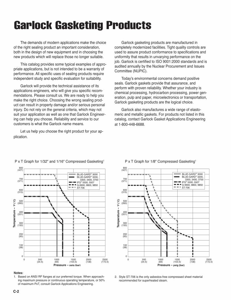
P x T Graph for 1/32" and 1/16" Compressed Gasketing1 P x T Graph for 1/8" Compressed Gasketing1
Notes: 1. Based on ANSI RF flanges at our preferred torque. When approach-
ing maximum pressure or continuous operating temperature, or 50% of maximum PxT, consult Garlock Applications Engineering.
2. Style ST-706 is the only asbestos-free compressed sheet material recommended for superheated steam.
Garlock gasketing products are manufactured in completely modernized facilities. Tight quality controls are used to assure product conformance to specifications and uniformity that results in unvarying performance on the job. Garlock is certified to ISO 9001:2000 standards and is audited annually by the Nuclear Procurement and Issues Committee (NUPIC).
Todayʼs environmental concerns demand positive seals. Garlock gaskets provide that assurance, and perform with proven reliability. Whether your industry is chemical processing, hydrocarbon processing, power gen-eration, pulp and paper, microelectronics or transportation, Garlock gasketing products are the logical choice.
Garlock also manufactures a wide range of elasto-meric and metallic gaskets. For products not listed in this catalog, contact Garlock Gasket Applications Engineering at 1-800-448-6688.
The demands of modern applications make the choice of the right sealing product an important consideration, both in the design of new equipment and in choosing the new products which will replace those no longer suitable.
This catalog provides some typical examples of appro-priate applications, but is not intended to be a warranty of performance. All specific uses of sealing products require independent study and specific evaluation for suitability.
Garlock will provide the technical assistance of its applications engineers, who will give you specific recom-mendations. Please consult us. We are ready to help you make the right choice. Choosing the wrong sealing prod-uct can result in property damage and/or serious personal injury. Do not rely on the general criteria, which may not suit your application as well as one that Garlock Engineer-ing can help you choose. Reliability and service to our customers is what the Garlock name means.
Let us help you choose the right product for your ap-plication.
800(427)
700(371)
600(315)
500(260)
400(201)
300(150)
200(95)
100(38)
00 500 1000 1500 2000 2500
(34.5) (69) (103.5) (138) (172.5)���������������������
������������������
���
BLUE-GARD® 3000BLUE-GARD® 3200, 3300, 3400, 3700IFG® 5500, 5507G-9900, 9800, 9850ST-706
C-3
I F
G® 550
0
Gene
ral S
ervic
e
Style
G-9
900
Hi
gh Te
mpe
ratu
re
Style
312
5SS/
TC
Hi
gh Te
mpe
ratu
re
Style
ST-
706
Sa
tura
ted,
Sup
erhe
ated
Ste
am
Style
350
0 GY
LON®
Ag
gres
sive
Chem
icals
St
yle 3
510
GYLO
N®
Aggr
essiv
e Ch
emica
ls
Style
354
5 GY
LON®
Ag
gres
sive
Chem
icals
1. Flange Metallic ■ ■ ■ ■ ■ ■ ■
Materials Non-Metallic *2. Continuous Ambient to 200°F Operating (20°C to 95°C) ■ ■ ■ ■ ■ ■ ■
Temperature 200°F to 300°F (COT) (95°C to 150°C) ■ ■ ■ ■ ■ ■ ■
300°F to 400°F (150°C to 205°C) ■ ■ ■ ■ ■ ■ ■
400°F to 500°F (205°C to 260°C) ■ ■ ■ ■ ■ ■ ■
500°F to 650°F (260°C to 345°C) ■ ■ ■ 650°F to 750°F (345°C to 400°C) ■ ■ 750°F to 1200°˚F (400°C to 650°C) * 3. Application Vacuum to 250 psig Pressure (Vacuum to 17 bar) ■ ■ ■ ■ ■ ■ ■
Vacuum to 1000 psig (Vacuum to 69 bar) ■ ■ ■ ■ ■ ■ ■
Vacuum to 1500 psig (Vacuum to 103 bar) ■ ■ ■ Vacuum to 2000 psig (Vacuum to 138 bar) ■ ■ 4. PxT Values 0 to 50,000 psig x °F (0 to 1,500 bar x °C) ■ ■ ■ ■ ■ ■ ■
0 to 350,000 psig x °F (0 to 12,000 bar x °C) ■ 1 ■ ■ ■ 2* ■ ■ ■
0 to 700,000 psig x °F (0 to 25,000 bar x °C) ■ 3 ■ 3
Quick Reference Selection Guide
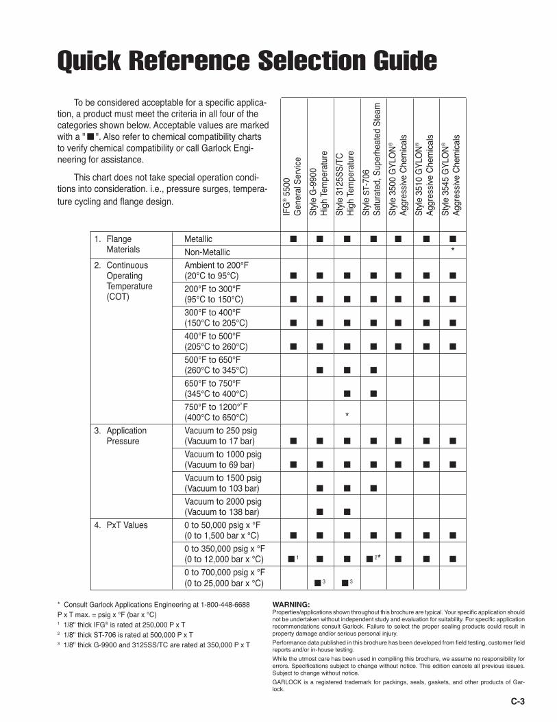
* Consult Garlock Applications Engineering at 1-800-448-6688P x T max. = psig x °F (bar x °C)1 1/8" thick IFG® is rated at 250,000 P x T2 1/8" thick ST-706 is rated at 500,000 P x T3 1/8" thick G-9900 and 3125SS/TC are rated at 350,000 P x T
To be considered acceptable for a specific applica-tion, a product must meet the criteria in all four of the categories shown below. Acceptable values are marked with a " ■ ". Also refer to chemical compatibility charts to verify chemical compatibility or call Garlock Engi-neering for assistance.
This chart does not take special operation condi-tions into consideration. i.e., pressure surges, tempera-ture cycling and flange design.
WARNING:Properties/applications shown throughout this brochure are typical. Your specific application should not be undertaken without independent study and evaluation for suitability. For specific application recommendations consult Garlock. Failure to select the proper sealing products could result in property damage and/or serious personal injury. Performance data published in this brochure has been developed from field testing, customer field reports and/or in-house testing. While the utmost care has been used in compiling this brochure, we assume no responsibility for errors. Specifications subject to change without notice. This edition cancels all previous issues. Subject to change without notice. GARLOCK is a registered trademark for packings, seals, gaskets, and other products of Gar-lock.
C-4
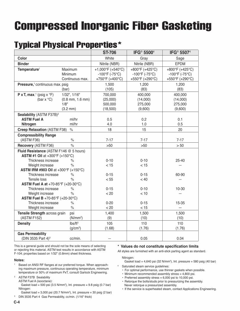
Compressed Inorganic Fiber Gasketing ST-706 IFG® 55004 IFG® 55074
Color White Gray SageBinder Nitrile (NBR) Nitrile (NBR) EPDMTemperature1 Maximum +1,000°F (+540°C) +800°F (+425°C) +800°F (+425°C) Minimum -100°F (-75°C) -100°F (-75°C) -100°F (-75°C) Continuous max. +750°F (+400°C) +550°F (+290°C) +550°F (+290°C)Pressure,1 continuous max. psig 1,500 1,200 1,200 (bar) (105) (83) (83) P x T, max.1 (psig x °F) 1/32", 1/16" 700,000 400,000 400,000 (bar x °C) (0.8 mm, 1.6 mm) (25,000) (14,000) (14,000) 1/8" 500,000 275,000 275,000 (3.2 mm) (18,500) (9,600) (9,600)Sealability (ASTM F37B)2 ASTM Fuel A ml/hr 0.5 0.2 0.1 Nitrogen ml/hr 4.0 1.0 0.5Creep Relaxation (ASTM F38) % 18 15 20Compressibility Range (ASTM F36) % 7-17 7-17 7-17Recovery (ASTM F36) % >50 >50 > 50Fluid Resistance (ASTM F146 @ 5 hours) ASTM #1 Oil at +300°F (+150°C) Thickness increase % 0-10 0-10 25-40 Weight increase % < 15 < 15 — ASTM IRM #903 Oil at +300°F (+150°C) Thickness increase % 0-15 0-15 60-90 Tensile loss % < 55 < 40 — ASTM Fuel A at +70-85°F (+20-30°C) Thickness increase % 0-15 0-10 10-30 Weight increase % < 20 < 10 — ASTM Fuel B +70-85°F (+20-30°C) Thickness increase % 0-20 0-15 15-35 Weight increase % < 20 < 15 —Tensile Strength across grain psi 1,400 1,500 1,500 (ASTM F152) (N/mm2) (9) (10) (10)Density lbs/ft3 105 110 110 (g/cm3) (1.68) (1.76) (1.76)Gas Permeability (DIN 3535 Part 4)3 cc/min. — 0.05 0.04
This is a general guide and should not be the sole means of selecting or rejecting this material. ASTM test results in accordance with ASTM F-104; properties based on 1/32" (0.8mm) sheet thickness.
Notes: 1 Based on ANSI RF flanges at our preferred torque. When approach-
ing maximum pressure, continuous operating temperature, minimum temperature or 50% of maximum PxT, consult Garlock Engineering.
2 ASTM F37B Sealability ASTM Fuel A (isooctane): Gasket load = 500 psi (3.5 N/mm2), Int. pressure = 9.8 psig (0.7 bar) Nitrogen: Gasket load = 3,000 psi (20.7 N/mm2), Int. pressure = 30 psig (2 bar)
3 DIN 3535 Part 4 Gas Permeability, cc/min. (1/16" thick)
Typical Physical Properties*
* Values do not constitute specification limitsAll styles are furnished with an anti-stick parting agent as standard.
Nitrogen: Gasket load = 4,640 psi (32 N/mm2), Int. pressure = 580 psig (40 bar)
4 Saturated steam service guidelines: • For optimal performance, use thinner gaskets when possible. • Minimum recommended assembly stress = 4,800 psi. • Preferred assembly stress = 6,000 psi to 10,000 psi. • Retorque the bolts/studs prior to pressurizing the assembly. Never retorque a pressurized assembly. • If the service is superheated steam, contact Applications Engineering.
C-5
Style ST-706
Benefits
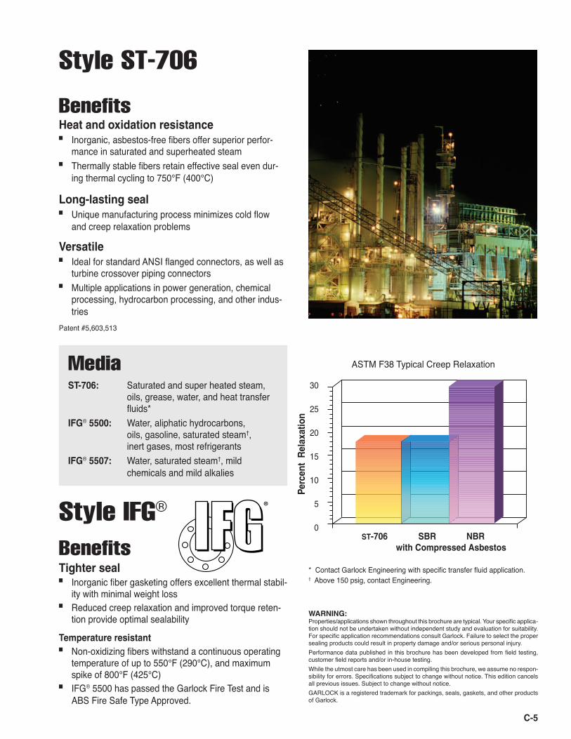
ASTM F38 Typical Creep Relaxation
WARNING:Properties/applications shown throughout this brochure are typical. Your specific applica-tion should not be undertaken without independent study and evaluation for suitability. For specific application recommendations consult Garlock. Failure to select the proper sealing products could result in property damage and/or serious personal injury. Performance data published in this brochure has been developed from field testing, customer field reports and/or in-house testing. While the utmost care has been used in compiling this brochure, we assume no respon-sibility for errors. Specifications subject to change without notice. This edition cancels all previous issues. Subject to change without notice. GARLOCK is a registered trademark for packings, seals, gaskets, and other products of Garlock.
30
25
20
15
10
5
0
Perc
ent
Rel
axat
ion
ST-706 SBR NBR with Compressed Asbestos
Heat and oxidation resistance■ Inorganic, asbestos-free fibers offer superior perfor-
mance in saturated and superheated steam■ Thermally stable fibers retain effective seal even dur-
ing thermal cycling to 750°F (400°C)
Long-lasting seal■ Unique manufacturing process minimizes cold flow
and creep relaxation problems
Versatile■ Ideal for standard ANSI flanged connectors, as well as
turbine crossover piping connectors ■ Multiple applications in power generation, chemical
processing, hydrocarbon processing, and other indus-tries
Patent #5,603,513
Style IFG®
Benefits
Media
ST-706: Saturated and super heated steam, oils, grease, water, and heat transfer fluids* IFG® 5500: Water, aliphatic hydrocarbons, oils, gasoline, saturated steam†, inert gases, most refrigerantsIFG® 5507: Water, saturated steam†, mild chemicals and mild alkalies
Tighter seal■ Inorganic fiber gasketing offers excellent thermal stabil-
ity with minimal weight loss■ Reduced creep relaxation and improved torque reten-
tion provide optimal sealability
Temperature resistant■ Non-oxidizing fibers withstand a continuous operating
temperature of up to 550°F (290°C), and maximum spike of 800°F (425°C)
■ IFG® 5500 has passed the Garlock Fire Test and is ABS Fire Safe Type Approved.
* Contact Garlock Engineering with specific transfer fluid application.† Above 150 psig, contact Engineering.
®
High Temp Compressed Graphite or Carbon Fiber Gasketing
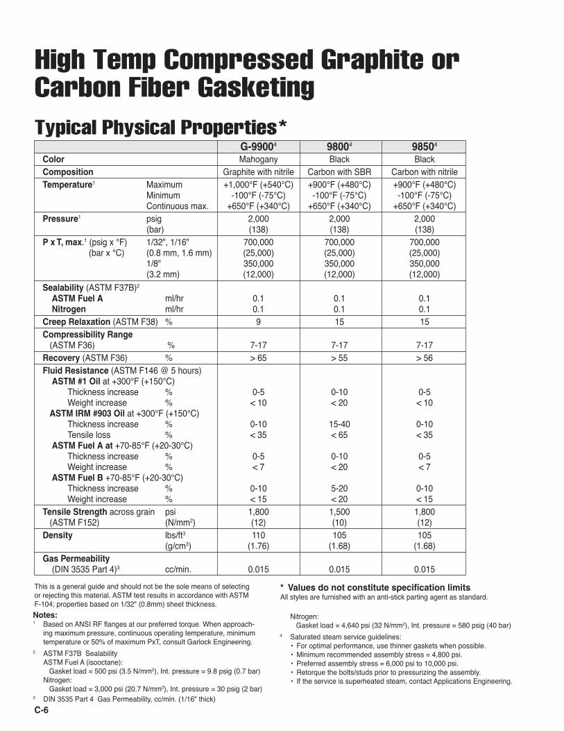
G-99004 98004 98504
Color Mahogany Black BlackComposition Graphite with nitrile Carbon with SBR Carbon with nitrileTemperature1 Maximum +1,000°F (+540°C) +900°F (+480°C) +900°F (+480°C) Minimum -100°F (-75°C) -100°F (-75°C) -100°F (-75°C) Continuous max. +650°F (+340°C) +650°F (+340°C) +650°F (+340°C)Pressure1 psig 2,000 2,000 2,000 (bar) (138) (138) (138)P x T, max.1 (psig x °F) 1/32", 1/16" 700,000 700,000 700,000 (bar x °C) (0.8 mm, 1.6 mm) (25,000) (25,000) (25,000) 1/8" 350,000 350,000 350,000 (3.2 mm) (12,000) (12,000) (12,000)Sealability (ASTM F37B)2 ASTM Fuel A ml/hr 0.1 0.1 0.1 Nitrogen ml/hr 0.1 0.1 0.1Creep Relaxation (ASTM F38) % 9 15 15Compressibility Range (ASTM F36) % 7-17 7-17 7-17Recovery (ASTM F36) % > 65 > 55 > 56Fluid Resistance (ASTM F146 @ 5 hours) ASTM #1 Oil at +300°F (+150°C) Thickness increase % 0-5 0-10 0-5 Weight increase % < 10 < 20 < 10 ASTM IRM #903 Oil at +300°F (+150°C) Thickness increase % 0-10 15-40 0-10 Tensile loss % < 35 < 65 < 35 ASTM Fuel A at +70-85°F (+20-30°C) Thickness increase % 0-5 0-10 0-5 Weight increase % < 7 < 20 < 7 ASTM Fuel B +70-85°F (+20-30°C) Thickness increase % 0-10 5-20 0-10 Weight increase % < 15 < 20 < 15Tensile Strength across grain psi 1,800 1,500 1,800 (ASTM F152) (N/mm2) (12) (10) (12)Density lbs/ft3 110 105 105 (g/cm3) (1.76) (1.68) (1.68)Gas Permeability (DIN 3535 Part 4)3 cc/min. 0.015 0.015 0.015
Notes: 1 Based on ANSI RF flanges at our preferred torque. When approach-
ing maximum pressure, continuous operating temperature, minimum temperature or 50% of maximum PxT, consult Garlock Engineering.
2 ASTM F37B Sealability ASTM Fuel A (isooctane): Gasket load = 500 psi (3.5 N/mm2), Int. pressure = 9.8 psig (0.7 bar) Nitrogen: Gasket load = 3,000 psi (20.7 N/mm2), Int. pressure = 30 psig (2 bar)
3 DIN 3535 Part 4 Gas Permeability, cc/min. (1/16" thick)
This is a general guide and should not be the sole means of selecting or rejecting this material. ASTM test results in accordance with ASTM F-104; properties based on 1/32" (0.8mm) sheet thickness.
Nitrogen: Gasket load = 4,640 psi (32 N/mm2), Int. pressure = 580 psig (40 bar)
4 Saturated steam service guidelines: • For optimal performance, use thinner gaskets when possible. • Minimum recommended assembly stress = 4,800 psi. • Preferred assembly stress = 6,000 psi to 10,000 psi. • Retorque the bolts/studs prior to pressurizing the assembly. • If the service is superheated steam, contact Applications Engineering.
* Values do not constitute specification limitsAll styles are furnished with an anti-stick parting agent as standard.
Typical Physical Properties*
C-6
WARNING:Properties/applications shown throughout this brochure are typical. Your specific applica-tion should not be undertaken without independent study and evaluation for suitability. For specific application recommendations consult Garlock. Failure to select the proper sealing products could result in property damage and/or serious personal injury. Performance data published in this brochure has been developed from field testing, customer field reports and/or in-house testing. While the utmost care has been used in compiling this brochure, we assume no respon-sibility for errors. Specifications subject to change without notice. This edition cancels all previous issues. Subject to change without notice. GARLOCK is a registered trademark for packings, seals, gaskets, and other products of Garlock.
Style G-9900 Hi-Temp Styles 9800 / 9850Benefits
Tough and reliable■ Graphite fiber gasketing withstands extreme tempera-
tures and pressures, as well as many chemicals■ Passed Garlock Fire tests, and is ABS Fire Safe Type
Approved■ Meets Navy Spec STR 508
Tighter seal■ Maintains superior seal during thermal cycling, even in
saturated steam and hot oils■ Significantly reduces emissions to meet stringent
Clean Air Act requirements
Easy to install■ Patented* graphite fiber sheet is easier to handle and
cut than exfoliated graphite sheets or metal-inserted gasket material
* Patent #4,859,526Note: For nuclear orders, specify Style G-9920.
Media
G-9900: Saturated steam, water, inert gases, aliphatic hydrocarbons, oils, gasoline, and most refrigerants9800: Saturated steam†, water, and inert gases9850: Water, saturated steam†, aliphatic hydro- carbons, oils, gasoline, most refrigerants
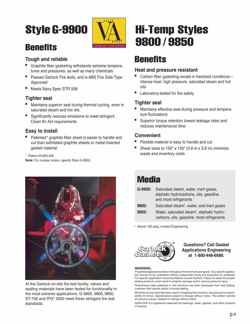
At the Garlock on-site fire test facility, valves and sealing materials have been tested for functionality in the most extreme applications. G-9900, 9800, 9850, ST-706 and IFG® 5500 meet these stringent fire test standards.
BenefitsHeat and pressure resistant■ Carbon fiber gasketing excels in harshest conditions—
intense heat, high pressure, saturated steam and hot oils
■ Laboratory-tested for fire safety
Tighter seal■ Maintains effective seal during pressure and tempera-
ture fluctuations■ Superior torque retention lowers leakage rates and
reduces maintenance time
Convenient■ Flexible material is easy to handle and cut■ Sheet sizes to 150" x 150" (3.8 m x 3.8 m) minimize
waste and inventory costs
GasketsGasketsGarlockGarlock
Questions? Call Gasket Applications Engineering
at 1-800-448-6688.
®
† Above 150 psig, contact Engineering.
� � � � � � � � � � � � �
� � � � � � � � � � � � �
� � � � � � � � � � � � � � � � � � � � � � � � � � � � � � � � � � � �
C-7
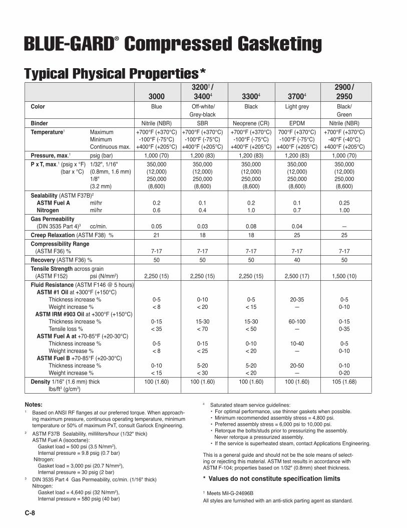
BLUE-GARD® Compressed Gasketing 3200† / 2900 /
3000 34004 33004 37004 2950Color Blue Off-white/ Black Light grey Black/ Grey-black GreenBinder Nitrile (NBR) SBR Neoprene (CR) EPDM Nitrile (NBR)Temperature1 Maximum +700°F (+370°C) +700°F (+370°C) +700°F (+370°C) 700°F (+370°C) +700°F (+370°C) Minimum -100°F (-75°C) -100°F (-75°C) -100°F (-75°C) -100°F (-75°C) -40°F (-40°C) Continuous max. +400°F (+205°C) +400°F (+205°C) +400°F (+205°C) +400°F (+205°C) +400°F (+205°C)Pressure, max.1 psig (bar) 1,000 (70) 1,200 (83) 1,200 (83) 1,200 (83) 1,000 (70)P x T, max.1 (psig x °F) 1/32", 1/16" 350,000 350,000 350,000 350,000 350,000 (bar x °C) (0.8mm, 1.6 mm) (12,000) (12,000) (12,000) (12,000) (12,000) 1/8" 250,000 250,000 250,000 250,000 250,000 (3.2 mm) (8,600) (8,600) (8,600) (8,600) (8,600)Sealability (ASTM F37B)2 ASTM Fuel A ml/hr 0.2 0.1 0.2 0.1 0.25 Nitrogen ml/hr 0.6 0.4 1.0 0.7 1.00Gas Permeability (DIN 3535 Part 4)3 cc/min. 0.05 0.03 0.08 0.04 —Creep Relaxation (ASTM F38) % 21 18 18 25 25Compressibility Range (ASTM F36) % 7-17 7-17 7-17 7-17 7-17Recovery (ASTM F36) % 50 50 50 40 50Tensile Strength across grain (ASTM F152) psi (N/mm2) 2,250 (15) 2,250 (15) 2,250 (15) 2,500 (17) 1,500 (10)Fluid Resistance (ASTM F146 @ 5 hours) ASTM #1 Oil at +300°F (+150°C) Thickness increase % 0-5 0-10 0-5 20-35 0-5 Weight increase % < 8 < 20 < 15 — 0-10 ASTM IRM #903 Oil at +300°F (+150°C) Thickness increase % 0-15 15-30 15-30 60-100 0-15 Tensile loss % < 35 < 70 < 50 — 0-35 ASTM Fuel A at +70-85°F (+20-30°C) Thickness increase % 0-5 0-15 0-10 10-40 0-5 Weight increase % < 8 < 25 < 20 — 0-10 ASTM Fuel B +70-85°F (+20-30°C) Thickness increase % 0-10 5-20 5-20 20-50 0-10 Weight increase % < 15 < 30 < 20 — 0-20Density 1/16" (1.6 mm) thick 100 (1.60) 100 (1.60) 100 (1.60) 100 (1.60) 105 (1.68) lbs/ft3 (g/cm3)
Notes: 1 Based on ANSI RF flanges at our preferred torque. When approach-
ing maximum pressure, continuous operating temperature, minimum temperature or 50% of maximum PxT, consult Garlock Engineering.
2 ASTM F37B Sealability, milliliters/hour (1/32" thick) ASTM Fuel A (isooctane): Gasket load = 500 psi (3.5 N/mm2), Internal pressure = 9.8 psig (0.7 bar) Nitrogen: Gasket load = 3,000 psi (20.7 N/mm2), Internal pressure = 30 psig (2 bar)
3 DIN 3535 Part 4 Gas Permeability, cc/min. (1/16" thick) Nitrogen: Gasket load = 4,640 psi (32 N/mm2), Internal pressure = 580 psig (40 bar)
4 Saturated steam service guidelines: • For optimal performance, use thinner gaskets when possible. • Minimum recommended assembly stress = 4,800 psi. • Preferred assembly stress = 6,000 psi to 10,000 psi. • Retorque the bolts/studs prior to pressurizing the assembly. Never retorque a pressurized assembly. • If the service is superheated steam, contact Applications Engineering.
Typical Physical Properties*
This is a general guide and should not be the sole means of select-ing or rejecting this material. ASTM test results in accordance with ASTM F-104; properties based on 1/32" (0.8mm) sheet thickness.
† Meets Mil-G-24696BAll styles are furnished with an anti-stick parting agent as standard.
* Values do not constitute specification limits
C-8
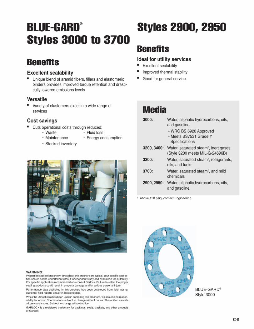
BLUE-GARD® Styles 3000 to 3700
BenefitsExcellent sealability■ Unique blend of aramid fibers, fillers and elastomeric
binders provides improved torque retention and drasti-cally lowered emissions levels
Versatile■ Variety of elastomers excel in a wide range of
services
Cost savings■ Cuts operational costs through reduced:
• Waste • Fluid loss • Maintenance • Energy consumption • Stocked inventory
WARNING:Properties/applications shown throughout this brochure are typical. Your specific applica-tion should not be undertaken without independent study and evaluation for suitability. For specific application recommendations consult Garlock. Failure to select the proper sealing products could result in property damage and/or serious personal injury. Performance data published in this brochure has been developed from field testing, customer field reports and/or in-house testing. While the utmost care has been used in compiling this brochure, we assume no respon-sibility for errors. Specifications subject to change without notice. This edition cancels all previous issues. Subject to change without notice. GARLOCK is a registered trademark for packings, seals, gaskets, and other products of Garlock.
C-9
Media
3000: Water, aliphatic hydrocarbons, oils, and gasoline - WRC BS 6920 Approved - Meets BS7531 Grade Y Specifications3200, 3400: Water, saturated steam†, inert gases (Style 3200 meets MIL-G-24696B)3300: Water, saturated steam†, refrigerants, oils, and fuels3700: Water, saturated steam†, and mild chemicals2900, 2950: Water, aliphatic hydrocarbons, oils, and gasoline
BenefitsIdeal for utility services■ Excellent sealability■ Improved thermal stability■ Good for general service
Styles 2900, 2950
† Above 150 psig, contact Engineering.
BLUE-GARD® Style 3000
C-10
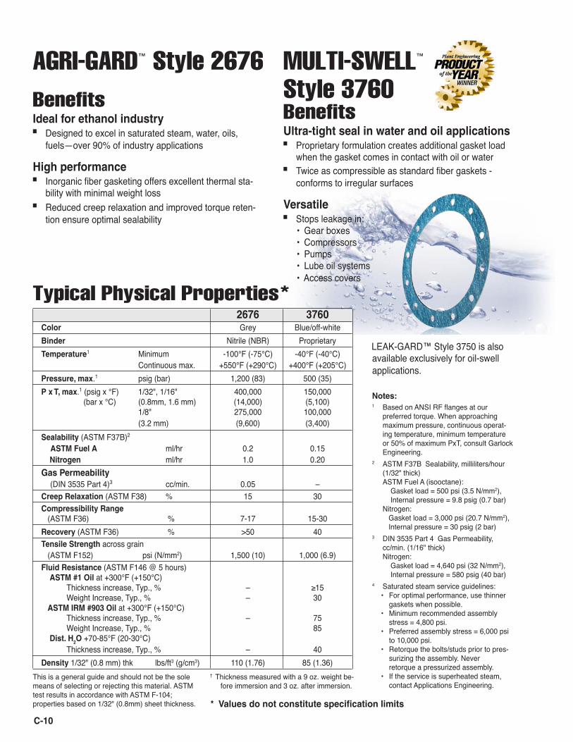
AGRI-GARD™ Style 2676 MULTI-SWELL™ Style 3760Benefits
Notes: 1 Based on ANSI RF flanges at our
preferred torque. When approaching maximum pressure, continuous operat-ing temperature, minimum temperature or 50% of maximum PxT, consult Garlock Engineering.
2 ASTM F37B Sealability, milliliters/hour (1/32" thick) ASTM Fuel A (isooctane): Gasket load = 500 psi (3.5 N/mm2), Internal pressure = 9.8 psig (0.7 bar) Nitrogen: Gasket load = 3,000 psi (20.7 N/mm2), Internal pressure = 30 psig (2 bar)
3 DIN 3535 Part 4 Gas Permeability, cc/min. (1/16" thick) Nitrogen: Gasket load = 4,640 psi (32 N/mm2), Internal pressure = 580 psig (40 bar)
4 Saturated steam service guidelines:• For optimal performance, use thinner
gaskets when possible.• Minimum recommended assembly
stress = 4,800 psi.• Preferred assembly stress = 6,000 psi
to 10,000 psi.• Retorque the bolts/studs prior to pres-
surizing the assembly. Never retorque a pressurized assembly.
• If the service is superheated steam, contact Applications Engineering.
BenefitsIdeal for ethanol industry■ Designed to excel in saturated steam, water, oils,
fuels—over 90% of industry applications
High performance■ Inorganic fiber gasketing offers excellent thermal sta-
bility with minimal weight loss■ Reduced creep relaxation and improved torque reten-
tion ensure optimal sealability
This is a general guide and should not be the sole means of selecting or rejecting this material. ASTM test results in accordance with ASTM F-104; properties based on 1/32" (0.8mm) sheet thickness. * Values do not constitute specification limits
Typical Physical Properties*
2676 3760Color Grey Blue/off-whiteBinder Nitrile (NBR) ProprietaryTemperature1 Minimum -100°F (-75°C) -40°F (-40°C) Continuous max. +550°F (+290°C) +400°F (+205°C)Pressure, max.1 psig (bar) 1,200 (83) 500 (35)P x T, max.1 (psig x °F) 1/32", 1/16" 400,000 150,000 (bar x °C) (0.8mm, 1.6 mm) (14,000) (5,100) 1/8" 275,000 100,000 (3.2 mm) (9,600) (3,400)Sealability (ASTM F37B)2 ASTM Fuel A ml/hr 0.2 0.15 Nitrogen ml/hr 1.0 0.20Gas Permeability (DIN 3535 Part 4)3 cc/min. 0.05 –Creep Relaxation (ASTM F38) % 15 30Compressibility Range (ASTM F36) % 7-17 15-30Recovery (ASTM F36) % >50 40Tensile Strength across grain (ASTM F152) psi (N/mm2) 1,500 (10) 1,000 (6.9)Fluid Resistance (ASTM F146 @ 5 hours) ASTM #1 Oil at +300°F (+150°C) Thickness increase, Typ., % – ≥15 Weight Increase, Typ., % – 30 ASTM IRM #903 Oil at +300°F (+150°C) Thickness increase, Typ., % – 75 Weight Increase, Typ., % 85 Dist. H2O +70-85°F (20-30°C) Thickness increase, Typ., % – 40Density 1/32" (0.8 mm) thk lbs/ft3 (g/cm3) 110 (1.76) 85 (1.36)
Ultra-tight seal in water and oil applications■ Proprietary formulation creates additional gasket load
when the gasket comes in contact with oil or water■ Twice as compressible as standard fiber gaskets -
conforms to irregular surfaces
Versatile■ Stops leakage in:
• Gear boxes • Compressors
• Pumps • Lube oil systems • Access covers
† Thickness measured with a 9 oz. weight be-fore immersion and 3 oz. after immersion.
LEAK-GARD™ Style 3750 is also available exclusively for oil-swell applications.

WARNING:Properties/applications shown throughout this brochure are typical. Your specific application should not be undertaken without independent study and evaluation for suitability. For specific application recommendations consult Garlock. Failure to select the proper sealing products could result in property damage and/or serious personal injury. Performance data published in this brochure has been developed from field testing, customer field reports and/or in-house testing. While the utmost care has been used in compiling this brochure, we assume no responsibility for errors. Specifications subject to change without notice. This edition cancels all previous issues. Subject to change without notice. GARLOCK is a registered trademark for packings, seals, gaskets, and other products of Garlock.
GYLON® Gasketing
C-11
Notes: 1 Based on ANSI RF flanges at our preferred torque. When approaching
maximum pressure, temperature or 50% of maximum PxT, consult Garlock Engineering. For Styles HP 3560 and HP 3561, consult Garlock if approaching maximum temperature, or 50% of maximum pressure or P x T.
2 For HP 3560 and HP 3561, 1/16" thickness only; for 3535, 1/4" thick- ness only.
3 ASTM F37B Sealability, milliliters/hour (1/32" thick) ASTM Fuel A (isooctane): Gasket load = 1,000 psi (7 N/mm2), Internal pressure = 9.8 psig (0.7 bar)
4 DIN 3535 Part 4 Gas Permeability, cc/min. (1/16" thick) Nitrogen: Internal pressure = 580 psig (40 bar), Gasket load = 4,640 psi (32 N/mm2)
GYLON® Styles 3500 3504 3510 3530 3540 3545 HP 3560 HP 3561 3565 3591 3594Color Fawn with Blue with Off-white with Black with White with White with Fawn with Off-white with White & blue Gold with Green with black brand black brand black brand no brand black brand black brand black brand black brand w/black brand black brand black brandComposition PTFE with PTFE with PTFE with PTFE with Microcellular Microcellular GYLON® with GYLON® with PTFE with PTFE with PTFE with silica glass barium graphite PTFE PTFE perforated perforated glass barium sulfate glass filler microspheres sulfate 316LSS insert 316LSS insert microspheresTemperature1 Minimum -450°F -450°F -450°F -450°F -450°F -450°F — — -450°F -450°F -450°F (-268°C) (-268°C) (-268°C) (-268°C) (-268°C) (-268°C) — — (-268°C) (-268°C) (-268°C) Cont. max. +500°F +500°F +500°F +500°F +500°F +500°F +500°F +500°F +500°F +500°F +500°F (+260°C) (+260°C) (+260°C) (+260°C) (+260°C) (+260°C) (+260°C) (+260°C) (+260°C) (+260°C) (+260°C)Pressure, psig 1,200 800 1,200 1,200 1,200 1,200 2,500 2,500 1,200 1,200 800 Cont. max.1 (bar) (83) (55) (83) (83) (83) (83) (172) (172) (83) (83) (55)P x T, max.1 1/32", 1/16" 350,000 350,000 350,000 350,000 350,000 350,000 700,0002 700,0002 350,000 350,000 350,000 (0.8 mm,1.6 mm) (12,000) (12,000) (12,000) (12,000) (12,000) (12,000) (25,000) (25,000) (12,000) (12,000) (12,000) psig x °F 1/8" 250,000 250,000 250,000 250,000 250,000 250,000 450,000 450,000 250,000 250,000 250,000 (bar x °C) (3.2 mm) (8,600) (8,600) (8,600) (8,600) (8,600) (8,600) (15,000) (15,000) (8,600) (8,600) (8,600)Sealability ASTM Fuel A ml/hr 0.22 0.12 0.04 0.02 0.25 0.15 0.022 0.012 0.33 0.20 0.50 (ASTM F37B)3 Gas Permeability cc/min. < 0.015 < 0.015 < 0.015 < 0.015 < 0.015 < 0.015 < 0.0152 < 0.0152 < 0.015 < 0.015 < 0.015 (DIN 3535 Part 4)4
Creep Relaxation % 18 40 11 29 10 15 202 202 35 35 30 (ASTM F38) Compressibility Range (ASTM F36) % 7-12 25-45 4-10 7-17 70-85 60-70 4-92 3-72 35-50 15-25 10-20Recovery % >40 >30 >40 >40 >8 >15 >452 >502 >35 >40 >45 (ASTM F36) Tensile Strength psi 2,000 2,000 2,000 3,000 — — 5,0002 5,0002 1,800 2,000 2,000 (ASTM D1708) (N/mm2) (14) (14) (14) (21) (34) (34) (13) (14) (14)Flammability Will not support flame Will not support flameBacterial Growth Will not support Will not support
This is a general guide and should not be the sole means of selecting or rejecting this material. ASTM test results in accordance with ASTM F-104; properties based on 1/32" (0.8mm) sheet thickness, except Style 3565, based on 1/16" (1.6mm).
Typical Physical Properties*
* Values do not constitute specification limits
C-12
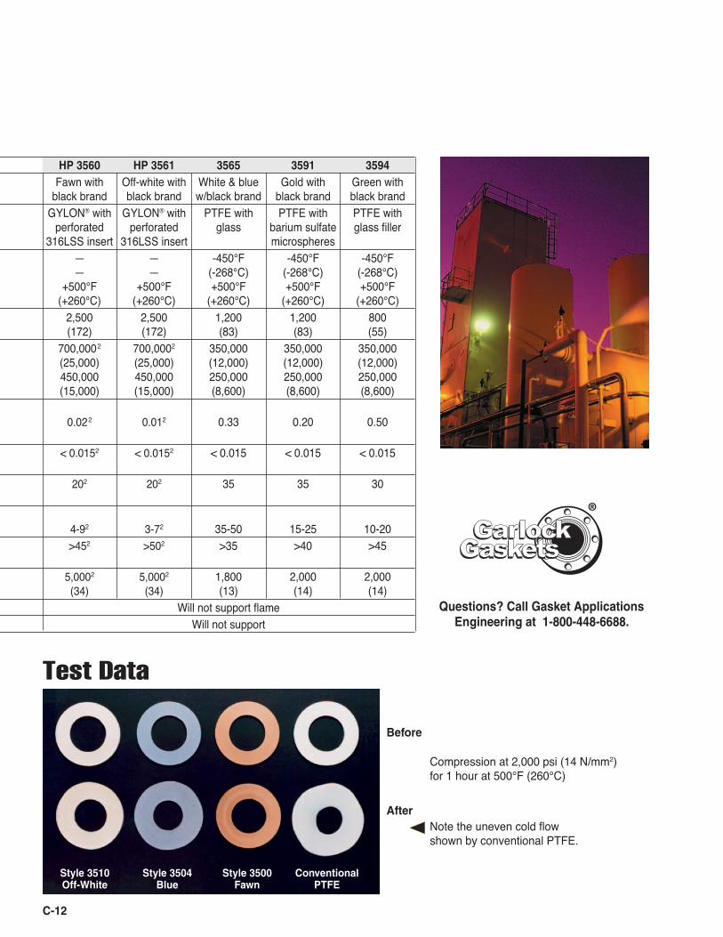
Test Data
Before
After
Compression at 2,000 psi (14 N/mm2) for 1 hour at 500°F (260°C)
Questions? Call Gasket Applications Engineering at 1-800-448-6688.
Note the uneven cold flow shown by conventional PTFE.
Style 3510 Style 3504 Style 3500 Conventional Off-White Blue Fawn PTFE
GasketsGasketsGarlockGarlock
®
HP 3560 HP 3561 3565 3591 3594 Fawn with Off-white with White & blue Gold with Green with black brand black brand w/black brand black brand black brand GYLON® with GYLON® with PTFE with PTFE with PTFE with perforated perforated glass barium sulfate glass filler 316LSS insert 316LSS insert microspheres — — -450°F -450°F -450°F — — (-268°C) (-268°C) (-268°C) +500°F +500°F +500°F +500°F +500°F (+260°C) (+260°C) (+260°C) (+260°C) (+260°C) 2,500 2,500 1,200 1,200 800 (172) (172) (83) (83) (55) 700,0002 700,0002 350,000 350,000 350,000 (25,000) (25,000) (12,000) (12,000) (12,000) 450,000 450,000 250,000 250,000 250,000 (15,000) (15,000) (8,600) (8,600) (8,600) 0.022 0.012 0.33 0.20 0.50
< 0.0152 < 0.0152 < 0.015 < 0.015 < 0.015 202 202 35 35 30
4-92 3-72 35-50 15-25 10-20 >452 >502 >35 >40 >45
5,0002 5,0002 1,800 2,000 2,000 (34) (34) (13) (14) (14) Will not support flame Will not support
C-13
Style 3535 Joint SealantBenefitsChemical resistance■ Pure PTFE is chemically
inert, withstands a wide range of chemicals
■ Conforms to FDA regulations
Easy to install■ Continuous length on spools is easily cut and formed■ Strong adhesive backing aids installation on narrow or
hard-to-reach flanges■ Available in widths from 1/8" to 1"
Notes: 1 ASTM F37B Sealability, milliliters/hour (1/4" thick)
ASTM Fuel A (isooctane): Gasket load: 3,000 psi (20.7 N/mm2), Internal pressure: 30 psig (2 bar)
2 DIN 3535 Part 4 Gas Permeability, cc/min. (1/4" thick) Nitrogen: Internal pressure: 580 psig (40 bar), Gasket load: 4,640 psi (32 N/mm2)
Typical Physical PropertiesSealability (ASTM F37B)1 ml/hr 0.1Gas Permeability (DIN 3535 Part 4)2 cc/min. 0.05
GYLON® Style 3530
Tighter seal■ Graphite-filled PTFE offers extremely low void con-
tent for minimal emissions
Chemical resistance■ Black GYLON® delivers long service against volatile
hazardous pollutants (VHAP and VOC)■ Withstands high concentrations of hydrofluoric
acids and other glass-dissolving media■ Also ideal for monomer service and cryogenics
Benefits
GYLON® Styles 3500 to 3510
Tighter seal■ Improved performance over conventional PTFE ■ Reduced product loss and emissions
Reduced creep relaxation■ Unique manufacturing process minimizes cold flow prob-
lems typical of skived and expanded PTFE sheets■ Excellent bolt torque retention
Chemical resistance■ Withstands a wide range of chemicals for extended ser-
vice life in a wide variety of applications
Cost savings■ Cuts operational costs through reduced:
• Fluid loss • Inventory costs • Energy consumption • Waste • Maintenance costs
Largest sheet sizes*■ Offers some of the largest sheet sizes in the industry■ Improved material utilization reduces waste
Branding and color coding■ Easy identification of superior GYLON® products■ Reduces misapplication and use of unauthorized,
inferior substitutes* 60" x 60" (1524 mm x 1524 mm), 70" x 70" (1778 mm x 1778 mm),
60" x 90" (1524 mm x 2286 mm)
Benefits
Media GYLON® 3500: Strong acids (except hydrofluoric), solvents, hydrocarbons, water, steam, chlorine, and cryogenics. Conforms to FDA regulations. (For oxygen service, specify "Style 3502 for oxygen service.")GYLON® 3504: Moderate concentrations of acids and some caustics, hydrocarbons, solvents, water, refrigerants, and cryogenics. Conforms to FDA regulations. (For oxygen service, specify "Style 3505 for oxygen service.")GYLON® 3510: Strong caustics, moderate acids, chlorine, gases, water, steam, hydrocarbons, and cryogenics. Conforms to FDA regulations. (For oxygen service, specify "Style 3503 for oxygen service.")
WARNING:Properties/applications shown throughout this brochure are typical. Your specific applica-tion should not be undertaken without independent study and evaluation for suitability. For specific application recommendations consult Garlock. Failure to select the proper sealing products could result in property damage and/or serious personal injury. Performance data published in this brochure has been developed from field testing, customer field reports and/or in-house testing. While the utmost care has been used in compiling this brochure, we assume no respon-sibility for errors. Specifications subject to change without notice. This edition cancels all previous issues. Subject to change without notice. GARLOCK is a registered trademark for packings, seals, gaskets, and other products of Garlock.
C-14
WINNERChemical Processingʼs
VAALER AWARD
■ Pure microcellular PTFE■ Similar to Style 3545, but without rigid core■ Ideal for wavy, warped, pitted, or scratched
fl anges, and for many types of fl at face* fl anges
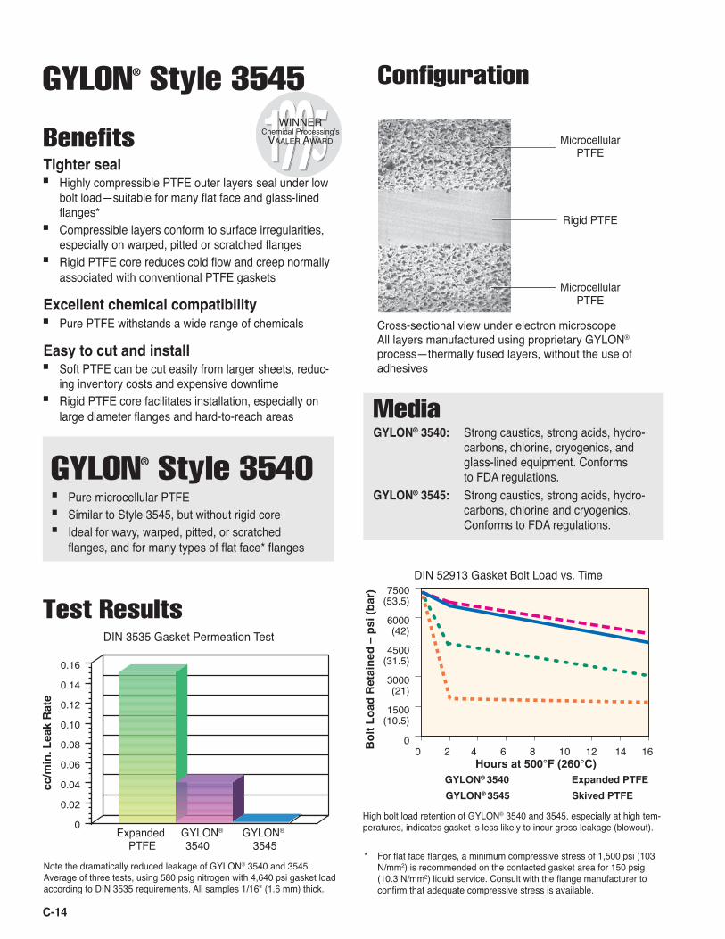
Test ResultsDIN 3535 Gasket Permeation Test
0.16
0.14
0.12
0.10
0.08
0.06
0.04
0.02
0
cc/m
in. L
eak
Rat
e
Expanded GYLON® GYLON®
PTFE 3540 3545
DIN 52913 Gasket Bolt Load vs. Time
Note the dramatically reduced leakage of GYLON® 3540 and 3545. Average of three tests, using 580 psig nitrogen with 4,640 psi gasket load according to DIN 3535 requirements. All samples 1/16" (1.6 mm) thick.
7500(53.5)
6000(42)
4500(31.5)
3000(21)
1500(10.5)
0Bo
lt L
oad
Ret
ain
ed –
psi
(b
ar)
High bolt load retention of GYLON® 3540 and 3545, especially at high tem-peratures, indicates gasket is less likely to incur gross leakage (blowout).
GYLON® Style 3545
Tighter seal■ Highly compressible PTFE outer layers seal under low
bolt load—suitable for many fl at face and glass-lined fl anges*
■ Compressible layers conform to surface irregularities, especially on warped, pitted or scratched fl anges
■ Rigid PTFE core reduces cold fl ow and creep normally associated with conventional PTFE gaskets
Excellent chemical compatibility■ Pure PTFE withstands a wide range of chemicals
Easy to cut and install■ Soft PTFE can be cut easily from larger sheets, reduc-
ing inventory costs and expensive downtime■ Rigid PTFE core facilitates installation, especially on
large diameter fl anges and hard-to-reach areas
Benefi ts
Confi guration
Cross-sectional view under electron microscopeAll layers manufactured using proprietary GYLON®
process—thermally fused layers, without the use of adhesives
MicrocellularPTFE
Rigid PTFE
MicrocellularPTFE
Media GYLON® 3540: Strong caustics, strong acids, hydro- carbons, chlorine, cryogenics, and glass-lined equipment. Conforms to FDA regulations. GYLON® 3545: Strong caustics, strong acids, hydro- carbons, chlorine and cryogenics. Conforms to FDA regulations.
GYLON® 3540
GYLON® 3545
Expanded PTFE
Skived PTFE
0 2 4 6 8 10 12 14 16Hours at 500°F (260°C)
* For fl at face fl anges, a minimum compressive stress of 1,500 psi (103 N/mm2) is recommended on the contacted gasket area for 150 psig (10.3 N/mm2) liquid service. Consult with the fl ange manufacturer to confi rm that adequate compressive stress is available.
GYLON® Style 3540
C-15
GYLON® Style 3565 ENVELON® Gasketing**
Tighter seal■ Soft, deformable exterior conforms to surface irregu-
larities; ideal for worn, warped or pitted flanges■ Stable blue core improves cold flow resistance■ Low bolt load requirements ensure a tight seal on
glass-lined or wavy flanges†
■ Direct sintering of GYLON® layers prevents leak paths and adhesive contamination
Easy to install■ Unitized construction avoids jacket foldover■ Rigid core facilitates installation of large gaskets
Minimizes inventory■ Custom-cut gaskets from large sheets offer conve-
nience while reducing costly inventory buildup■ Ideal replacement for slit, milled, formed shield and
double jacketed envelope gaskets†
Benefits
WARNING:Properties/applications shown throughout this brochure are typical. Your specific appli-cation should not be undertaken without independent study and evaluation for suitability. For specific application recommendations consult Garlock. Failure to select the proper sealing products could result in property damage and/or serious personal injury. Performance data published in this brochure has been developed from field testing, customer field reports and/or in-house testing. While the utmost care has been used in compiling this brochure, we assume no responsibility for errors. Specifications subject to change without notice. This edition cancels all previous issues. Subject to change without notice. GARLOCK is a registered trademark for packings, seals, gaskets, and other products of Garlock.
* Consult Garlock Applications Engineering when using flanges in pres-sure classes above 300 lbs.
** Patents #4,961,891; #4,900,629† When sealing uneven flanges, gasket must be four times thicker than
maximum gap between flanges.
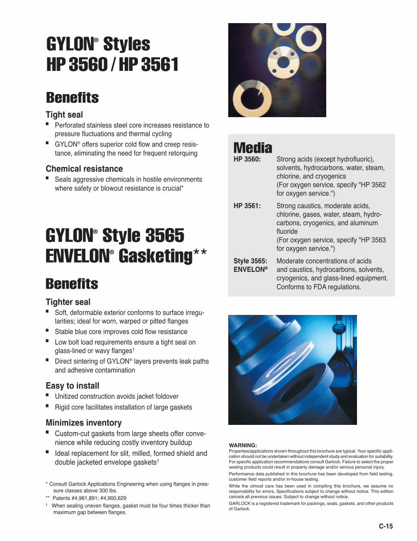
GYLON® Styles HP 3560 /
HP 3561
Tight seal■ Perforated stainless steel core increases resistance to
pressure fluctuations and thermal cycling■ GYLON® offers superior cold flow and creep resis-
tance, eliminating the need for frequent retorquing
Chemical resistance■ Seals aggressive chemicals in hostile environments
where safety or blowout resistance is crucial*
Benefits
Media HP 3560: Strong acids (except hydrofluoric), solvents, hydrocarbons, water, steam, chlorine, and cryogenics (For oxygen service, specify "HP 3562 for oxygen service.")HP 3561: Strong caustics, moderate acids, chlorine, gases, water, steam, hydro- carbons, cryogenics, and aluminum fluoride (For oxygen service, specify "HP 3563 for oxygen service.")Style 3565: Moderate concentrations of acids ENVELON® and caustics, hydrocarbons, solvents, cryogenics, and glass-lined equipment. Conforms to FDA regulations.
C-16
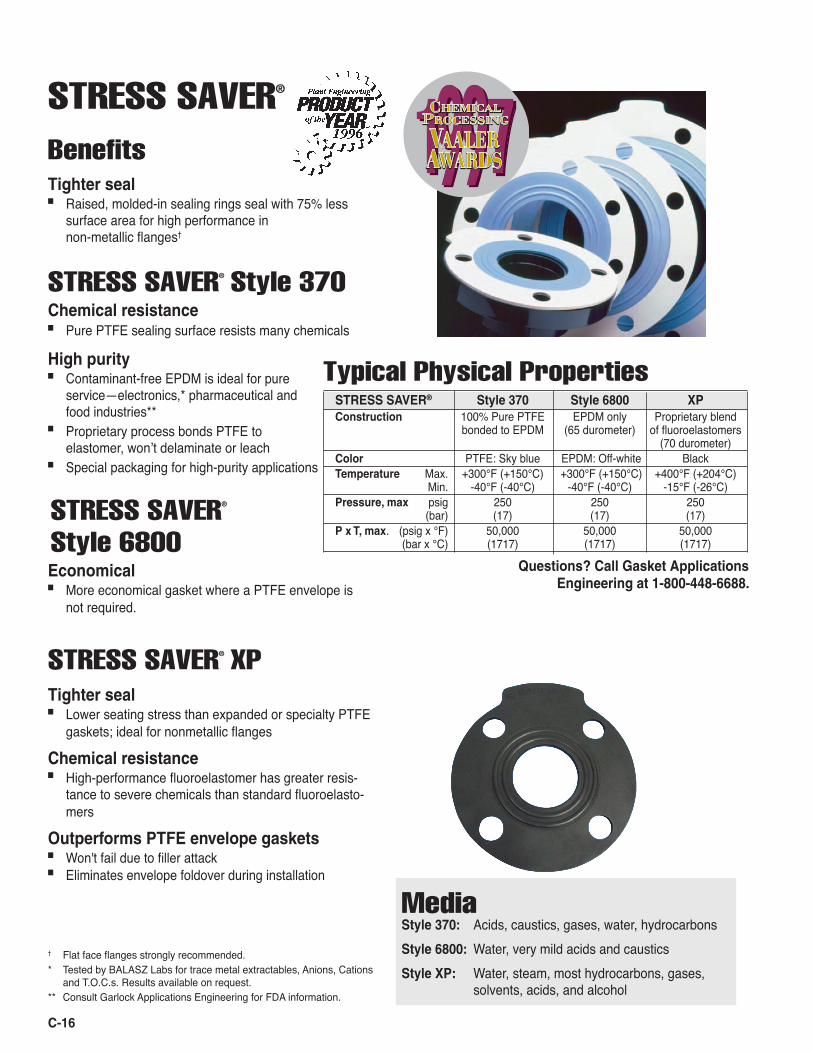
STRESS SAVER®
BenefitsTighter seal■ Raised, molded-in sealing rings seal with 75% less
surface area for high performance in non-metallic flanges†
STRESS SAVER® Style 370Chemical resistance■ Pure PTFE sealing surface resists many chemicals
High purity■ Contaminant-free EPDM is ideal for pure
service—electronics,* pharmaceutical and food industries**
■ Proprietary process bonds PTFE to elastomer, wonʼt delaminate or leach
■ Special packaging for high-purity applications
STRESS SAVER®
Style 6800Economical■ More economical gasket where a PTFE envelope is
not required.
† Flat face flanges strongly recommended.* Tested by BALASZ Labs for trace metal extractables, Anions, Cations
and T.O.C.s. Results available on request.** Consult Garlock Applications Engineering for FDA information.
Questions? Call Gasket Applications Engineering at 1-800-448-6688.
Typical Physical PropertiesSTRESS SAVER® Style 370 Style 6800 XP Construction 100% Pure PTFE EPDM only Proprietary blend bonded to EPDM (65 durometer) of fluoroelastomers (70 durometer)Color PTFE: Sky blue EPDM: Off-white BlackTemperature Max. +300°F (+150°C) +300°F (+150°C) +400°F (+204°C) Min. -40°F (-40°C) -40°F (-40°C) -15°F (-26°C)Pressure, max psig 250 250 250 (bar) (17) (17) (17)P x T, max. (psig x °F) 50,000 50,000 50,000 (bar x °C) (1717) (1717) (1717)
Media Style 370: Acids, caustics, gases, water, hydrocarbonsStyle 6800: Water, very mild acids and causticsStyle XP: Water, steam, most hydrocarbons, gases, solvents, acids, and alcohol
STRESS SAVER® XPTighter seal■ Lower seating stress than expanded or specialty PTFE
gaskets; ideal for nonmetallic flanges
Chemical resistance■ High-performance fluoroelastomer has greater resis-
tance to severe chemicals than standard fluoroelasto-mers
Outperforms PTFE envelope gaskets■ Won't fail due to filler attack■ Eliminates envelope foldover during installation
C-17
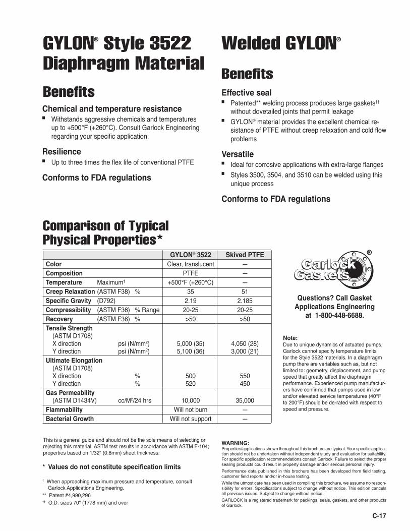
GYLON® Style 3522 Diaphragm Material
Chemical and temperature resistance■ Withstands aggressive chemicals and temperatures
up to +500°F (+260°C). Consult Garlock Engineering regarding your specific application.
Resilience■ Up to three times the flex life of conventional PTFE
Conforms to FDA regulations
Benefits
This is a general guide and should not be the sole means of selecting or rejecting this material. ASTM test results in accordance with ASTM F-104; properties based on 1/32" (0.8mm) sheet thickness.
† When approaching maximum pressure and temperature, consult Garlock Applications Engineering.** Patent #4,990,296†† O.D. sizes 70" (1778 mm) and over
* Values do not constitute specification limits
Welded GYLON®
Effective seal■ Patented** welding process produces large gaskets††
without dovetailed joints that permit leakage■ GYLON® material provides the excellent chemical re-
sistance of PTFE without creep relaxation and cold flow problems
Versatile■ Ideal for corrosive applications with extra-large flanges■ Styles 3500, 3504, and 3510 can be welded using this
unique process
Conforms to FDA regulations
Benefits
WARNING:Properties/applications shown throughout this brochure are typical. Your specific applica-tion should not be undertaken without independent study and evaluation for suitability. For specific application recommendations consult Garlock. Failure to select the proper sealing products could result in property damage and/or serious personal injury. Performance data published in this brochure has been developed from field testing, customer field reports and/or in-house testing. While the utmost care has been used in compiling this brochure, we assume no respon-sibility for errors. Specifications subject to change without notice. This edition cancels all previous issues. Subject to change without notice. GARLOCK is a registered trademark for packings, seals, gaskets, and other products of Garlock.
GYLON® 3522 Skived PTFEColor Clear, translucent —Composition PTFE —Temperature Maximum† +500°F (+260°C) —Creep Relaxation (ASTM F38) % 35 51Specific Gravity (D792) 2.19 2.185Compressibility (ASTM F36) % Range 20-25 20-25Recovery (ASTM F36) % >50 >50Tensile Strength (ASTM D1708) X direction psi (N/mm2) 5,000 (35) 4,050 (28) Y direction psi (N/mm2) 5,100 (36) 3,000 (21)Ultimate Elongation (ASTM D1708) X direction % 500 550 Y direction % 520 450Gas Permeability (ASTM D1434V) cc/M2/24 hrs 10,000 35,000Flammability Will not burn —Bacterial Growth Will not support —
Comparison of Typical Physical Properties*
Questions? Call Gasket Applications Engineering
at 1-800-448-6688.
GasketsGasketsGarlockGarlock
®
Note: Due to unique dynamics of actuated pumps, Garlock cannot specify temperature limits for the Style 3522 materials. In a diaphragm pump there are variables such as, but not limited to: geometry, displacement, and pump speed that greatly affect the diaphragm performance. Experienced pump manufactur-ers have confirmed that pumps used in low and/or elevated service temperatures (40°F to 200°F) should be de-rated with respect to speed and pressure.

GRAPH-LOCK® Gasketing
BenefitsExcellent resistance■ Pure exfoliated graphite flake material excels in
extreme conditions, withstanding heat, pressure, and aggressive chemicals
■ Proven fire-safe
Reliable seal■ Seals easily under moderate bolt load, offers
superior torque retention■ Retains dimensional stability in high temperatures;
seals tightly even during pressure fluctuations
Also available: Style 3120: Nuclear-grade homogeneous sheetStyle 3122: High-purity homogeneous sheet
Versatility■ Available in two grades—industrial grade is 98% pure;
nuclear grade is 99.5% pure■ Available as standard homogeneous sheet or metal-
inserted sheet for applications requiring extra strength
C-18
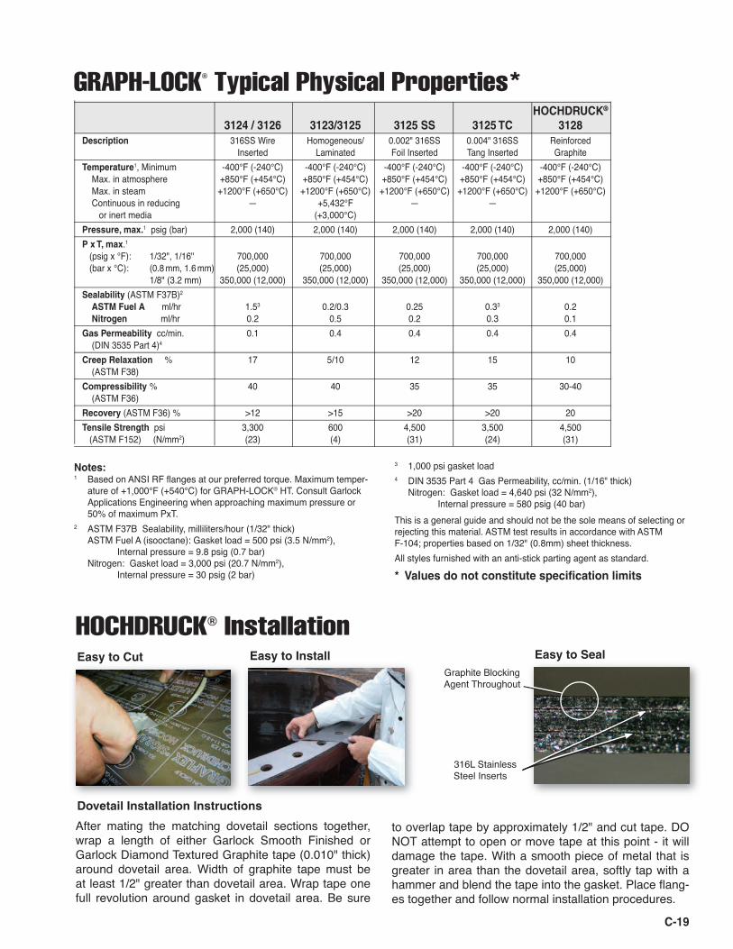
HOCHDRUCK® Style 3128 Gasketing
■ Easy and safe to handle without breakage■ Anti-scratch and anti-stick properties built in surface of
gasket■ Seals much tighter than standard graphite gaskets■ Available with reduced sulfur (3128RS) and with
1000ºF temperature rating (3128HT)■ Dove-tails seal tightly
Easy to install■ Can be cut with a utility knife■ Remains flat during installation
Benefits
High-Performance Reinforced graphite gasket material with improved sealability characteristics
WARNING:Properties/applications shown throughout this brochure are typical. Your specific applica-tion should not be undertaken without independent study and evaluation for suitability. For specific application recommendations consult Garlock. Failure to select the proper sealing products could result in property damage and/or serious personal injury. Performance data published in this brochure has been developed from field testing, customer field reports and/or in-house testing. While the utmost care has been used in compiling this brochure, we assume no respon-sibility for errors. Specifications subject to change without notice. This edition cancels all previous issues. Subject to change without notice. GARLOCK is a registered trademark for packings, seals, gaskets, and other products of Garlock.
C-19
HOCHDRUCK® 3124 / 3126 3123/3125 3125 SS 3125 TC 3128
Description 316SS Wire Homogeneous/ 0.002" 316SS 0.004" 316SS Reinforced Inserted Laminated Foil Inserted Tang Inserted GraphiteTemperature1, Minimum -400°F (-240°C) -400°F (-240°C) -400°F (-240°C) -400°F (-240°C) -400°F (-240°C) Max. in atmosphere +850°F (+454°C) +850°F (+454°C) +850°F (+454°C) +850°F (+454°C) +850°F (+454°C) Max. in steam +1200°F (+650°C) +1200°F (+650°C) +1200°F (+650°C) +1200°F (+650°C) +1200°F (+650°C) Continuous in reducing — +5,432°F — — or inert media (+3,000°C)
Pressure, max.1 psig (bar) 2,000 (140) 2,000 (140) 2,000 (140) 2,000 (140) 2,000 (140)P x T, max.1
(psig x °F): 1/32", 1/16" 700,000 700,000 700,000 700,000 700,000 (bar x °C): (0.8 mm, 1.6 mm) (25,000) (25,000) (25,000) (25,000) (25,000) 1/8" (3.2 mm) 350,000 (12,000) 350,000 (12,000) 350,000 (12,000) 350,000 (12,000) 350,000 (12,000)Sealability (ASTM F37B)2
ASTM Fuel A ml/hr 1.53 0.2/0.3 0.25 0.33 0.2 Nitrogen ml/hr 0.2 0.5 0.2 0.3 0.1Gas Permeability cc/min. 0.1 0.4 0.4 0.4 0.4 (DIN 3535 Part 4)4
Creep Relaxation % 17 5/10 12 15 10 (ASTM F38) Compressibility % 40 40 35 35 30-40 (ASTM F36) Recovery (ASTM F36) % >12 >15 >20 >20 20Tensile Strength psi 3,300 600 4,500 3,500 4,500 (ASTM F152) (N/mm2) (23) (4) (31) (24) (31)
Notes: 1 Based on ANSI RF fl anges at our preferred torque. Maximum temper-
ature of +1,000°F (+540°C) for GRAPH-LOCK® HT. Consult Garlock Applications Engineering when approaching maximum pressure or 50% of maximum PxT.
2 ASTM F37B Sealability, milliliters/hour (1/32" thick)ASTM Fuel A (isooctane): Gasket load = 500 psi (3.5 N/mm2), Internal pressure = 9.8 psig (0.7 bar)Nitrogen: Gasket load = 3,000 psi (20.7 N/mm2), Internal pressure = 30 psig (2 bar)
This is a general guide and should not be the sole means of selecting or rejecting this material. ASTM test results in accordance with ASTM F-104; properties based on 1/32" (0.8mm) sheet thickness.All styles furnished with an anti-stick parting agent as standard.
* Values do not constitute specifi cation limits
GRAPH-LOCK® Typical Physical Properties*
3 1,000 psi gasket load4 DIN 3535 Part 4 Gas Permeability, cc/min. (1/16" thick)
Nitrogen: Gasket load = 4,640 psi (32 N/mm2), Internal pressure = 580 psig (40 bar)
Easy to Cut Easy to Install
After mating the matching dovetail sections together, wrap a length of either Garlock Smooth Finished or Garlock Diamond Textured Graphite tape (0.010" thick) around dovetail area. Width of graphite tape must be at least 1/2" greater than dovetail area. Wrap tape one full revolution around gasket in dovetail area. Be sure
Dovetail Installation Instructions
Easy to SealGraphite Blocking Agent Throughout
316L Stainless Steel Inserts
HOCHDRUCK® Installation
to overlap tape by approximately 1/2" and cut tape. DO NOT attempt to open or move tape at this point - it will damage the tape. With a smooth piece of metal that is greater in area than the dovetail area, softly tap with a hammer and blend the tape into the gasket. Place fl ang-es together and follow normal installation procedures.
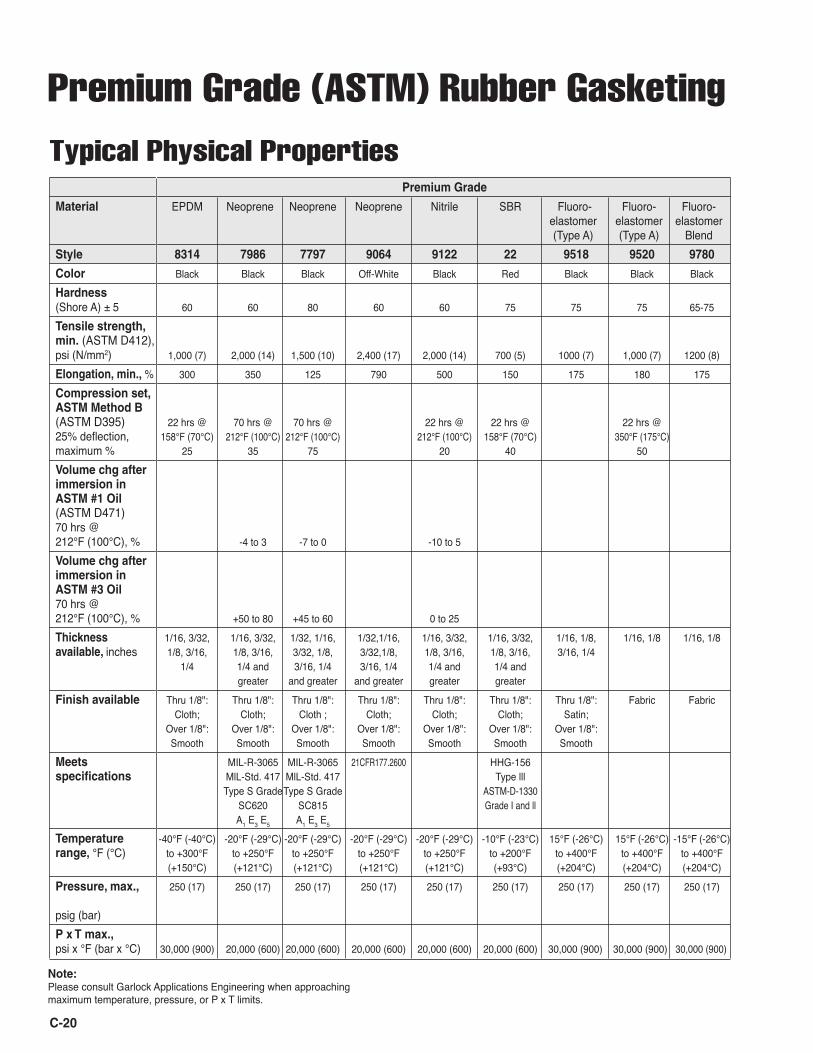
Premium Grade
Material EPDM Neoprene Neoprene Neoprene Nitrile SBR Fluoro- Fluoro- Fluoro- elastomer elastomer elastomer (Type A) (Type A) Blend Style 8314 7986 7797 9064 9122 22 9518 9520 9780
Color Black Black Black Off-White Black Red Black Black Black
Hardness (Shore A) ± 5 60 60 80 60 60 75 75 75 65-75
Tensile strength, min. (ASTM D412), psi (N/mm2) 1,000 (7) 2,000 (14) 1,500 (10) 2,400 (17) 2,000 (14) 700 (5) 1000 (7) 1,000 (7) 1200 (8)
Elongation, min., % 300 350 125 790 500 150 175 180 175
Compression set, ASTM Method B (ASTM D395) 22 hrs @ 70 hrs @ 70 hrs @ 22 hrs @ 22 hrs @ 22 hrs @ 25% deflection, 158°F (70°C) 212°F (100°C) 212°F (100°C) 212°F (100°C) 158°F (70°C) 350°F (175°C) maximum % 25 35 75 20 40 50 Volume chg after immersion in ASTM #1 Oil (ASTM D471) 70 hrs @ 212°F (100°C), % -4 to 3 -7 to 0 -10 to 5 Volume chg after immersion in ASTM #3 Oil 70 hrs @ 212°F (100°C), % +50 to 80 +45 to 60 0 to 25 Thickness 1/16, 3/32, 1/16, 3/32, 1/32, 1/16, 1/32,1/16, 1/16, 3/32, 1/16, 3/32, 1/16, 1/8, 1/16, 1/8 1/16, 1/8 available, inches 1/8, 3/16, 1/8, 3/16, 3/32, 1/8, 3/32,1/8, 1/8, 3/16, 1/8, 3/16, 3/16, 1/4 1/4 1/4 and 3/16, 1/4 3/16, 1/4 1/4 and 1/4 and greater and greater and greater greater greater Finish available Thru 1/8": Thru 1/8": Thru 1/8": Thru 1/8": Thru 1/8": Thru 1/8": Thru 1/8": Fabric Fabric Cloth; Cloth; Cloth ; Cloth; Cloth; Cloth; Satin; Over 1/8": Over 1/8": Over 1/8": Over 1/8": Over 1/8": Over 1/8": Over 1/8": Smooth Smooth Smooth Smooth Smooth Smooth Smooth Meets MIL-R-3065 MIL-R-3065 21CFR177.2600 HHG-156 specifications MlL-Std. 417 MlL-Std. 417 Type lll Type S Grade Type S Grade ASTM-D-1330 SC620 SC815 Grade I and ll A1 E3 E5 A1 E3 E5 Temperature -40°F (-40°C) -20°F (-29°C) -20°F (-29°C) -20°F (-29°C) -20°F (-29°C) -10°F (-23°C) 15°F (-26°C) 15°F (-26°C) -15°F (-26°C) range, °F (°C) to +300°F to +250°F to +250°F to +250°F to +250°F to +200°F to +400°F to +400°F to +400°F (+150°C) (+121°C) (+121°C) (+121°C) (+121°C) (+93°C) (+204°C) (+204°C) (+204°C)
Pressure, max., 250 (17) 250 (17) 250 (17) 250 (17) 250 (17) 250 (17) 250 (17) 250 (17) 250 (17) psig (bar)P x T max., psi x °F (bar x °C) 30,000 (900) 20,000 (600) 20,000 (600) 20,000 (600) 20,000 (600) 20,000 (600) 30,000 (900) 30,000 (900) 30,000 (900)
C-20
Premium Grade (ASTM) Rubber Gasketing
Typical Physical Properties
Note: Please consult Garlock Applications Engineering when approaching maximum temperature, pressure, or P x T limits.
C-21
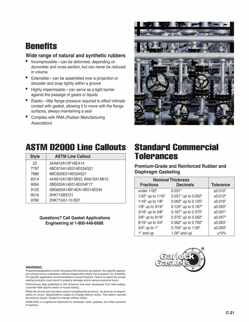
ASTM D2000 Line Callouts
BenefitsWide range of natural and synthetic rubbers■ Incompressible—can be deformed, depending on
durometer and cross section, but can never be reduced in volume
■ Extensible—can be assembled over a projection or shoulder and snap tightly within a groove
■ Highly impermeable—can serve as a tight barrier against the passage of gases or liquids
■ Elastic—little flange pressure required to effect intimate contact with gasket, allowing it to move with the flange surfaces, always maintaining a seal
■ Complies with RMA (Rubber Manufacturing Association)
Standard Commercial TolerancesPremium-Grade and Reinforced Rubber and Diaphragm Gasketing
Nominal Thickness Fractions Decimals Tolerance under 1/32" 0.031" ±0.010" 1/32" up to 1/16" 0.031" up to 0.062" ±0.012" 1/16" up to 1/8" 0.062" up to 0.125" ±0.016" 1/8" up to 3/16" 0.125" up to 0.187" ±0.020" 3/16" up to 3/8" 0.187" up to 0.375" ±0.031" 3/8" up to 9/16" 0.375" up to 0.562" ±0.047" 9/16" up to 3/4" 0.562" up to 0.750" ±0.063" 3/4" up to 1" 0.750" up to 1.00" ±0.093" 1" and up 1.00" and up ±10%
WARNING:Properties/applications shown throughout this brochure are typical. Your specific applica-tion should not be undertaken without independent study and evaluation for suitability. For specific application recommendations consult Garlock. Failure to select the proper sealing products could result in property damage and/or serious personal injury. Performance data published in this brochure has been developed from field testing, customer field reports and/or in-house testing. While the utmost care has been used in compiling this brochure, we assume no respon-sibility for errors. Specifications subject to change without notice. This edition cancels all previous issues. Subject to change without notice. GARLOCK is a registered trademark for packings, seals, gaskets, and other products of Garlock.
Style ASTM Line Callout
22 2AA810A13F16EA14 7797 4BC815A14E014E034G21 7986 6BC620E014E034G21 8314 4AA610A13B13B33, BA610A14B13 9064 2BE620A14E014E034F17 9122 5BG620A14B14EA14E014E034 9518 2HK710B3721 9780 2HK715A1-10 B37
GasketsGasketsGarlockGarlock
®
Questions? Call Gasket Applications Engineering at 1-800-448-6688.
C-22
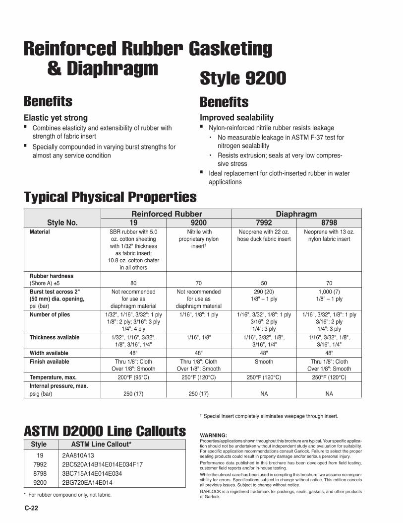
Reinforced Rubber Gasketing & Diaphragm
WARNING:Properties/applications shown throughout this brochure are typical. Your specific applica-tion should not be undertaken without independent study and evaluation for suitability. For specific application recommendations consult Garlock. Failure to select the proper sealing products could result in property damage and/or serious personal injury. Performance data published in this brochure has been developed from field testing, customer field reports and/or in-house testing. While the utmost care has been used in compiling this brochure, we assume no respon-sibility for errors. Specifications subject to change without notice. This edition cancels all previous issues. Subject to change without notice. GARLOCK is a registered trademark for packings, seals, gaskets, and other products of Garlock.
Style No. 19 9200 7992 8798 Material SBR rubber with 5.0 Nitrile with Neoprene with 22 oz. Neoprene with 13 oz. oz. cotton sheeting proprietary nylon hose duck fabric insert nylon fabric insert with 1/32" thickness insert† as fabric insert; 10.8 oz. cotton chafer in all others Rubber hardness (Shore A) ±5 80 70 50 70 Burst test across 2" Not recommended Not recommended 290 (20) 1,000 (7) (50 mm) dia. opening, for use as for use as 1/8" – 1 ply 1/8" – 1 ply psi (bar) diaphragm material diaphragm material Number of plies 1/32", 1/16", 3/32": 1 ply 1/16", 1/8": 1 ply 1/16", 3/32", 1/8": 1 ply 1/16", 3/32", 1/8": 1 ply 1/8": 2 ply; 3/16": 3 ply 3/16": 2 ply 3/16": 2 ply 1/4": 4 ply 1/4": 3 ply 1/4": 3 ply Thickness available 1/32", 1/16", 3/32", 1/16", 1/8" 1/16", 3/32", 1/8", 1/16", 3/32", 1/8", 1/8", 3/16", 1/4" 3/16", 1/4" 3/16", 1/4" Width available 48" 48" 48" 48" Finish available Thru 1/8": Cloth Thru 1/8": Cloth Smooth Thru 1/8": Cloth Over 1/8": Smooth Over 1/8": Smooth Over 1/8": Smooth Temperature, max. 200°F (95°C) 250°F (120°C) 250°F (120°C) 250°F (120°C) Internal pressure, max. psig (bar) 250 (17) 250 (17) NA NA
Typical Physical Properties
* For rubber compound only, not fabric.
BenefitsElastic yet strong■ Combines elasticity and extensibility of rubber with
strength of fabric insert■ Specially compounded in varying burst strengths for
almost any service condition
Benefits
Style 9200
Improved sealability■ Nylon-reinforced nitrile rubber resists leakage • No measurable leakage in ASTM F-37 test for
nitrogen sealability • Resists extrusion; seals at very low compres-
sive stress■ Ideal replacement for cloth-inserted rubber in water
applications
ASTM D2000 Line Callouts Style ASTM Line Callout*
19 2AA810A13 7992 2BC520A14B14E014E034F17 8798 3BC715A14E014E034 9200 2BG720EA14E014
† Special insert completely eliminates weepage through insert.
Reinforced Rubber Diaphragm
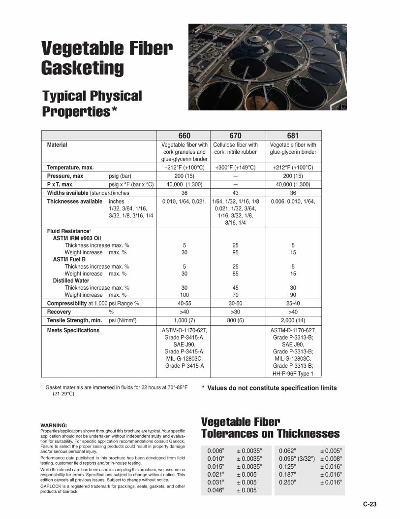
Vegetable Fiber Gasketing
WARNING:Properties/applications shown throughout this brochure are typical. Your specific application should not be undertaken without independent study and evalua-tion for suitability. For specific application recommendations consult Garlock. Failure to select the proper sealing products could result in property damage and/or serious personal injury. Performance data published in this brochure has been developed from field testing, customer field reports and/or in-house testing. While the utmost care has been used in compiling this brochure, we assume no responsibility for errors. Specifications subject to change without notice. This edition cancels all previous issues. Subject to change without notice. GARLOCK is a registered trademark for packings, seals, gaskets, and other products of Garlock.
0.006" ± 0.0035"0.010" ± 0.0035"0.015" ± 0.0035"0.021" ± 0.005"0.031" ± 0.005"0.046" ± 0.005"
Vegetable FiberTolerances on Thicknesses
0.062" ± 0.005"0.096" (3/32") ± 0.008"0.125" ± 0.016"0.187" ± 0.016"0.250" ± 0.016"
Typical Physical Properties*
C-23
660 670 681Material Vegetable fiber with Cellulose fiber with Vegetable fiber with cork granules and cork, nitrile rubber glue-glycerin binder glue-glycerin binder Temperature, max. +212°F (+100°C) +300°F (+149°C) +212°F (+100°C)Pressure, max psig (bar) 200 (15) — 200 (15)P x T, max. psig x °F (bar x °C) 40,000 (1,300) — 40,000 (1,300)Widths available (standard)inches 36 43 36Thicknesses available inches 0.010, 1/64, 0.021, 1/64, 1/32, 1/16, 1/8 0.006, 0.010, 1/64, 1/32, 3/64, 1/16, 0.021, 1/32, 3/64, 3/32, 1/8, 3/16, 1/4 1/16, 3/32, 1/8, 3/16, 1/4Fluid Resistance1 ASTM IRM #903 Oil Thickness increase max. % 5 25 5 Weight increase max. % 30 95 15 ASTM Fuel B Thickness increase max. % 5 25 5 Weight increase max. % 30 85 15 Distilled Water Thickness increase max. % 30 45 30 Weight increase max. % 100 70 90Compressibility at 1,000 psi Range % 40-55 30-50 25-40Recovery % >40 >30 >40Tensile Strength, min. psi (N/mm2) 1,000 (7) 800 (6) 2,000 (14)Meets Specifications ASTM-D-1170-62T, ASTM-D-1170-62T, Grade P-3415-A; Grade P-3313-B; SAE J90, SAE J90, Grade P-3415-A; Grade P-3313-B; MIL-G-12803C, MIL-G-12803C, Grade P-3415-A Grade P-3313-B; HH-P-96F Type 1
1 Gasket materials are immersed in fluids for 22 hours at 70°-85°F (21-29°C).
* Values do not constitute specification limits
C-24
Factors Affecting Gasket Performance
A gasket has one basic function: to create a positive seal between two relatively stationary parts. The gasket must do a number of different jobs well to function prop-erly: first, create an initial seal; second, maintain the seal over a desired length of time; third, be easily removed and replaced. Varying degrees of success are dependent on how well the gasket does the following: 1. Seals system fluid. 2. Chemically resists the system fluid to prevent serious
impairment of its physical properties. 3. Deforms enough to flow into the imperfections on the
gasket seating surfaces to provide intimate contact between the gasket and the seating surfaces.
4. Withstands system temperatures without serious impairment of its performance properties.
5. Is resilient and resists creep enough to maintain an adequate portion of the applied load.
6. Has sufficient strength to resist crushing under the applied load, and maintain its integrity when being handled and installed.
7. Does not contaminate the system fluid. 8. Does not promote corrosion of the gasket seating
surfaces. 9. Is easily and cleanly removable at the time of replace-
ment.
During the gasket product selection process that fol-lows, we recommend that these nine (9) factors be used as a checklist from the viewpoint of the userʼs degree of need for each factor and the manufacturerʼs degree of compliance.
Gasket SelectionSelecting gasketing materials for particular appli-
cations is not an easy task. The variables present in a flanged connection seem endless and yet all of them must be taken into consideration to assure a proper seal. In the past, the acronym "TAMP" (Temperature, Application, Media and Pressure) seemed to give sufficient information to make a gasketing recommendation. Today, items such as: the flange metallurgy, the amount of bolt thread em-bedment, the amount of flange rotation, the amount of bolt stretch, the additives to the media and the flange surface finish (in addition to other variables) determine how well a gasket will perform. In general, the definition of what a seal is has changed drastically over the years. Leakage measurements have gone from drips a minute to parts per million.
This catalog is designed to help guide you through the various gasketing products and narrow your choices. All industry standard tests are included in order to allow an end user a means of comparison between different materi-als. Many of the test procedures require that the tests be conducted on 1/32" material. As a rule of thumb, gasket performance decreases as material thickness increases. In addition, compressive loads must be increased with thicker materials. Proper bolting sequences are neces-sary to ensure those compressive loads are uniform. The temperature, pressure and P x T ratings are all based on optimum conditions. When approaching those extremes, it is suggested that you consult with the Garlock Applications Engineering Department or possibly upgrade to a material that has higher ratings.
As industry standards change and new products are introduced, this catalog will be updated. In the mean-time, we urge you to take advantage of our experienced personnel for assistance. In-plant training, instructional video tapes, additional technical information and gasketing recommendations all are available to help in your selec-tion process. Please feel free to call, fax, write, or e-mail us should you have any questions or concerns. Garlock is here to help.
Questions? Call Gasket Applications Engineering at 1-800-448-6688
WARNING:Properties/applications shown throughout this brochure are typical. Your specific applica-tion should not be undertaken without independent study and evaluation for suitability. For specific application recommendations consult Garlock. Failure to select the proper sealing products could result in property damage and/or serious personal injury. Performance data published in this brochure has been developed from field testing, customer field reports and/or in-house testing. While the utmost care has been used in compiling this brochure, we assume no respon-sibility for errors. Specifications subject to change without notice. This edition cancels all previous issues. Subject to change without notice. GARLOCK is a registered trademark for packings, seals, gaskets, and other products of Garlock.
C-25
TemperatureIn most selection processes, the temperature of the
fluid at the gasketed joint should be considered first. This will reduce the number of product candidates quickly, es-pecially as temperatures go from 200°F (95°C) to 1,000°F (540°C). When system operating temperatures approach a particular gasket materialʼs maximum continuous operating temperature limit, an upgrade to a superior material is sug-gested. In some situations cryogenic temperatures must also be considered.
ApplicationThe most important information under Application is
the type of flange and bolts used. The number, size and grade of bolts used in the application determines the load available. The surface area being compressed is calcu-lated from the gasket contact dimensions. The load from the bolts and the contact area of the gasket result in the compressive load available to seal the gasket. We have calculated and tabulated this information on standard ANSI raised face flanges (see page C-45). Compressive stress available on non-standard flanges must be calculated on an individual basis. Without this information, we cannot choose between various types of materials such as elasto-meric (rubber) gaskets, compressed sheet, GRAPH-LOCK® and GYLON® styles.
MediaThere are thousands of different fluids. We cannot, in
this manual, make recommendations for all fluids. Fortu-nately, however, there are a relatively limited number of fluids that make up the vast majority of the media encoun-tered in industry. A general overview of fluid compatibility is provided for the most popular styles shown in this manual (see Chemical Resistance chart, pages C-26 to C-38). System cleanout and flushes should also be considered. Additional information on products versus fluids is available upon request.
PressureNext to be considered is the internal pressure of the
fluid at the gasketed joint. We list the maximum pres-sure limits for each style. If severe and frequent pressure changes are involved, we should be given the details, since an alternative product may be needed.
Pressure (psi or bar) x Temperature (°F or °C) We strongly recommend that pressure and tempera-
ture be considered simultaneously by using the following procedure:1. First select the Garlock style(s) being considered for
your application/service,2. List the maximum pressure, temperature and P x T
value for the style(s),3. Make sure the actual service conditions do not exceed
the style limitations in any of the three criteria. If they donʼt, the style(s) can be used, provided all other requirements are met. If they do exceed any one limit, another style or styles should be considered. Rarely can a style be recommended when the service condi-tions of pressure and temperature are both at the maximum limits for that style.
Example: BLUE-GARD® Compressed Asbestos-free Gasketing Style 30001. Pressure Limit: 1,000 psig (70 bar)2. Maximum Temperature Limit: 700°F (370°C);
Continuous Operating Temp.: 400°F (205°C)3. P x T Limit: 350,000* (12,000)
At 1,000 psig (70 bar), maximum temperature is 350°F (180°C).
ImportantMaximum pressure and P x T ratings are based on
the use of ANSI RF flanges at our preferred torque. The ratings were developed using laboratory tests at ideal gasketing conditions. Field conditions will undoubtedly affect the gasket performance.
When approaching maximum pressure, continu-ous operating temperature, minimum temperature or 50% of maximum PxT, consult Garlock Applications Engineering.
We hasten to point out that this method for gasket selection is merely a general guide and should not be the sole means for selecting or rejecting a product.* P x T based on 1/16" sheet thickness unless otherwise stated.
GasketsGasketsGarlockGarlock
®
C-26
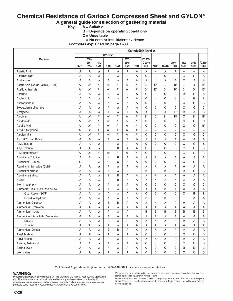
Chemical Resistance of Garlock Compressed Sheet and GYLON®
A general guide for selection of gasketing material Key: A = Suitable B = Depends on operating conditions C = Unsuitable – = No data or insufficient evidence Footnotes explained on page C-38.
Call Gasket Applications Engineering at 1-800-448-6688 for specific recommendations.
Abietic Acid A A A A A A A A – A A – – –Acetaldehyde A A A A A A A C C C C C C BAcetamide A A A A A A A A C A A C A BAcetic Acid (Crude, Glacial, Pure) A1 A1 A1 A1 A1 A1 A1 B1 B1 B1 B1 B1 B1 B1
Acetic Anhydride A1 A1 A1 A1 A1 A1 A1 B1 B1 B1 B1 B1 B1 B1
Acetone A A A A A A A C B C C B B AAcetonitrile A A A A A A A C – C C – B BAcetophenone A A A A A A A C C C C C C B2-Acetylaminofluorene A A A A A A A C C C C C C CAcetylene A A A A A A A A B A A12 B A BAcrolein A1 A1 A1 A1 A1 A1 A1 B1 C B1 B1 C B1 B1
Acrylamide A1 A1 A1 A1 A1 A1 A1 C C C C C C CAcrylic Acid A1 A1 A1 A1 A1 A1 A1 C C C C C C B1
Acrylic Anhydride A1 A1 A1 A1 A1 A1 A1 – – – – – – –Acrylonitrile A1 A1 A1 A1 A1 A1 A1 C C C C C C CAir (300ºF and Below) A A A A A A A A A A A A A AAllyl Acetate A A A A A A A C C C C C C BAllyl Chloride A A A B B A A C C C C C C BAllyl Methacrylate A1 A1 A1 A1 A1 A1 A1 C C C C C C CAluminum Chloride A A A B B A A A A A A A A AAluminum Fluoride C – A C C A A C C C C C C CAluminum Hydroxide (Solid) A A A A A A A A A A A A A AAluminum Nitrate A A A A A A – B B B B B B BAluminum Sulfate A A A B B A A A A A A A A AAlums A A A B B A A A A A A A A A4-Aminodiphenyl A A A A A A A C C C C C C CAmmonia, Gas, 150°F and below A A A A A A A A A B A A A A Gas, Above 150°F A A A A A A A C C C C C B B Liquid, Anhydrous A A A A A A A B – B B – A AAmmonium Chloride A A A B B A A A A A A A A AAmmonium Hydroxide A A A A A A A A A A A A A AAmmonium Nitrate A A A A A A – B B B B B B BAmmonium Phosphate, Monobasic A A A A A A A A A A A A A A Dibasic A A A A A A A A A A A A A A Tribasic A A A A A A A A A A A A A AAmmonium Sulfate A A A B B A A A A A A A A AAmyl Acetate A A A A A A A C C C C C C BAmyl Alcohol A A A A A A A A A A A A A AAniline, Aniline Oil A A A A A A A C C C C C C BAniline Dyes A A A A A A A C B C C B B Bo-Anisidine A A A A A A A C C C C C C C
WARNING:Properties/applications shown throughout this brochure are typical. Your specific application should not be undertaken without independent study and evaluation for suitability. For specific application recommendations consult Garlock. Failure to select the proper sealing products could result in property damage and/or serious personal injury.
Performance data published in this brochure has been developed from field testing, cus-tomer field reports and/or in-house testing. While the utmost care has been used in compiling this brochure, we assume no respon-sibility for errors. Specifications subject to change without notice. This edition cancels all previous issues.
Garlock Style Number
GYLON® Medium 3504 3535 IFG 5500 3565 3510 3540 G-9900 290014 3200 2930 IFG 5507 3500 3594 3591 3560 3561 3545 3530 9850 9800 ST-706 3000 3400 3300 3700
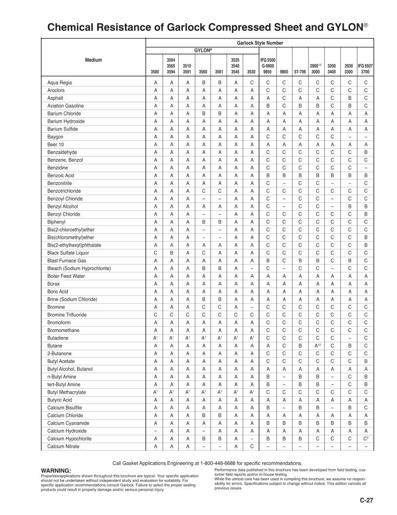
Chemical Resistance of Garlock Compressed Sheet and GYLON®
WARNING:Properties/applications shown throughout this brochure are typical. Your specific application should not be undertaken without independent study and evaluation for suitability. For specific application recommendations consult Garlock. Failure to select the proper sealing products could result in property damage and/or serious personal injury.
Performance data published in this brochure has been developed from field testing, cus-tomer field reports and/or in-house testing. While the utmost care has been used in compiling this brochure, we assume no respon-sibility for errors. Specifications subject to change without notice. This edition cancels all previous issues.
Call Gasket Applications Engineering at 1-800-448-6688 for specific recommendations.
Garlock Style Number
GYLON®
Medium 3504 3535 IFG 5500 3565 3510 3540 G-9900 290014 3200 2930 IFG 5507 3500 3594 3591 3560 3561 3545 3530 9850 9800 ST-706 3000 3400 3300 3700
Aqua Regia A A A B B A C C C C C C C CAroclors A A A A A A A C C C C C C CAsphalt A A A A A A A A C A A C B CAviation Gasoline A A A A A A A B C B B C B CBarium Chloride A A A B B A A A A A A A A ABarium Hydroxide A A A A A A A A A A A A A ABarium Sulfide A A A A A A A A A A A A A ABaygon A A A A A A A C C C C C – –Beer 10 A A A A A A A A A A A A A ABenzaldehyde A A A A A A A C C C C C C BBenzene, Benzol A A A A A A A C C C C C C CBenzidine A A A A A A A C C C C C C –Benzoic Acid A A A A A A A B B B B B B BBenzonitrile A A A A A A A C – C C – – CBenzotrichloride A A A C C A A C C C C C C CBenzoyl Chloride A A A – – A A C – C C – C CBenzyl Alcohol A A A A A A A C – C C – B BBenzyl Chloride A A A – – A A C C C C C C BBiphenyl A A A B B A A C C C C C C CBis(2-chloroethyl)ether A A A – – A A C C C C C C CBis(chloromethyl)ether A A A – – A A C C C C C C BBis(2-ethylhexyl)phthalate A A A A A A A C C C C C C BBlack Sulfate Liquor C B A C A A A C C C C C C CBlast Furnace Gas A A A A A A A B C B B C B CBleach (Sodium Hyprochlorite) A A A B B A – C – C C – C CBoiler Feed Water A A A A A A A A A A A A A ABorax A A A A A A A A A A A A A ABoric Acid A A A A A A A A A A A A A ABrine (Sodium Chloride) A A A B B A A A A A A A A ABromine A A A C C A – C C C C C C CBromine Trifluoride C C C C C C C C C C C C C CBromoform A A A A A A A C C C C C C CBromomethane A A A A A A A C C C C C C CButadiene A1 A1 A1 A1 A1 A1 A1 C C C C C – CButane A A A A A A A A C B A12 C B C2-Butanone A A A A A A A C C C C C C CButyl Acetate A A A A A A A C C C C C C BButyl Alcohol, Butanol A A A A A A A A A A A A A An-Butyl Amine A A A A A A A B – B B – C Btert-Butyl Amine A A A A A A A B – B B – C BButyl Methacrylate A1 A1 A1 A1 A1 A1 A1 C C C C C C CButyric Acid A A A A A A A A A A A A A ACalcium Bisulfite A A A A A A A B – B B – B CCalcium Chloride A A A B B A A A A A A A A ACalcium Cyanamide A A A A A A A B B B B B B BCalcium Hydroxide – A A – A A A A A A A A A ACalcium Hypochlorite A A A B B A – B B B C C C C2
Calcium Nitrate A A A – – A C – – – – – – –
C-27
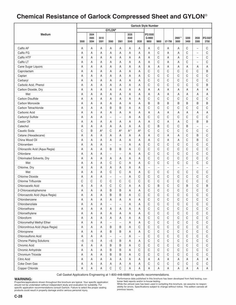
Chemical Resistance of Garlock Compressed Sheet and GYLON®
WARNING:Properties/applications shown throughout this brochure are typical. Your specific application should not be undertaken without independent study and evaluation for suitability. For specific application recommendations consult Garlock. Failure to select the proper sealing products could result in property damage and/or serious personal injury.
Performance data published in this brochure has been developed from field testing, cus-tomer field reports and/or in-house testing. While the utmost care has been used in compiling this brochure, we assume no respon-sibility for errors. Specifications subject to change without notice. This edition cancels all previous issues.
Call Gasket Applications Engineering at 1-800-448-6688 for specific recommendations.
Garlock Style Number
GYLON® Medium 3504 3535 IFG 5500 3565 3510 3540 G-9900 290014 3200 2930 IFG 5507 3500 3594 3591 3560 3561 3545 3530 9850 9800 ST-706 3000 3400 3300 3700
Calflo AF A A A A A A A A C A A C – CCalflo FG A A A A A A A A C A A C – CCalflo HTF A A A A A A A A C A A C – CCalflo LT A A A A A A A A C A A C – CCane Sugar Liquors A A A A A A A A A A A A A ACaprolactam A A A A A A A C C C C C C BCaptan A A A A A A A C C C C C C CCarbaryl A A A A A A A C C C C C C CCarbolic Acid, Phenol A A A A A A A C C C C C C BCarbon Dioxide, Dry A A A A A A A A A A A A A A Wet A A A A A A A A A A A A A ACarbon Disulfide A A A A A A A C C C C C C CCarbon Monoxide A A A A A A A B B B B B B BCarbon Tetrachloride A A A B B A A C C C C C C CCarbonic Acid A A A A A A A A A A A A A ACarbonyl Sulfide A A A – – A A C C C C C C CCastor Oil A A A A A A A A C A A C B BCatechol A A A A A A A C B C C B – –Caustic Soda C B A6 C A6 A11 A6 C C C C C C CCetane (Hexadecane) A A A A A A A A C A A C B CChina Wood Oil A A A A A A A A C A A C B CChloramben A A A – – A A C C C C C C CChlorazotic Acid (Aqua Regia) A A A B B A C C C C C C C CChlordane A A A – – A A C C C C C C CChlorinated Solvents, Dry A A A A A A A C C C C C C C Wet A A A C C A A C C C C C C CChlorine, Dry A A A A A A A – – – – – – – Wet A A A C C A A C C C C C C CChlorine Dioxide A A A – – A C C C C C C C CChlorine Trifluoride C C C C C C C C C C C C C CChloroacetic Acid A A A C C A A C B C C B C B2-Chloroacetophenone A A A B B A A C C C C C C CChloroazotic Acid (Aqua Regia) A A A B B A C C C C C C C CChlorobenzene A A A A A A A C C C C C C CChlorobenzilate A A A – – A A C C C C C C CChloroethane A A A A A A A C C C C C C CChloroethylene A A A A A A A C C C C C C CChloroform A A A A A A A C C C C C C CChloromethyl Methyl Ether A A A – – A A C C C C C C CChloronitrous Acid (Aqua Regia) A A A B B A C C C C C C C CChloroprene A A A B B A A C C C C C C CChlorosulfonic Acid A A A – – A – C C C C C C CChrome Plating Solutions –5 –5 A –5 B A A C C C C C C CChromic Acid A A A B B A C C C C C C C CChromic Anhydride A A A B B A C C C C C C C CChromium Trioxide A A A B B A C C C C C C C CCitric Acid A A A A A A A A A A A A A ACoke Oven Gas A A A A A A A C C C C C C CCopper Chloride A A A C C A A A A A A A A A
C-28
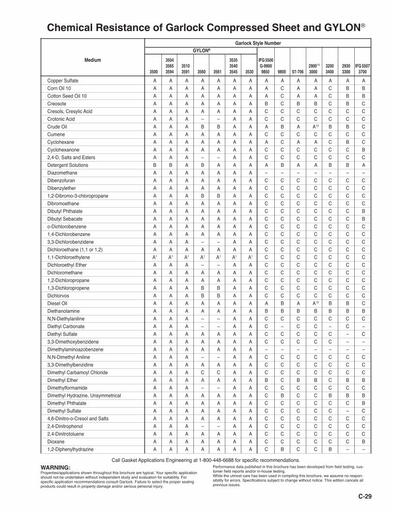
Chemical Resistance of Garlock Compressed Sheet and GYLON®
WARNING:Properties/applications shown throughout this brochure are typical. Your specific application should not be undertaken without independent study and evaluation for suitability. For specific application recommendations consult Garlock. Failure to select the proper sealing products could result in property damage and/or serious personal injury.
Performance data published in this brochure has been developed from field testing, cus-tomer field reports and/or in-house testing. While the utmost care has been used in compiling this brochure, we assume no respon-sibility for errors. Specifications subject to change without notice. This edition cancels all previous issues.
Call Gasket Applications Engineering at 1-800-448-6688 for specific recommendations.
Garlock Style Number
GYLON®
Medium 3504 3535 IFG 5500 3565 3510 3540 G-9900 290014 3200 2930 IFG 5507 3500 3594 3591 3560 3561 3545 3530 9850 9800 ST-706 3000 3400 3300 3700
Copper Sulfate A A A A A A A A A A A A A ACorn Oil 10 A A A A A A A A C A A C B BCotton Seed Oil 10 A A A A A A A A C A A C B BCreosote A A A A A A A B C B B C B CCresols, Cresylic Acid A A A A A A A C C C C C C CCrotonic Acid A A A – – A A C C C C C C CCrude Oil A A A B B A A A B A A12 B B CCumene A A A A A A A C C C C C C CCyclohexane A A A A A A A A C A A C B CCyclohexanone A A A A A A A C C C C C C B2,4-D, Salts and Esters A A A – – A A C C C C C C CDetergent Solutions B B A B A A A A B A A B B ADiazomethane A A A A A A A – – – – – – –Dibenzofuran A A A A A A A C C C C C C CDibenzylether A A A A A A A C C C C C C C1,2-Dibromo-3-chloropropane A A A B B A A C C C C C C CDibromoethane A A A A A A A C C C C C C CDibutyl Phthalate A A A A A A A C C C C C C BDibutyl Sebacate A A A A A A A C C C C C C Bo-Dichlorobenzene A A A A A A A C C C C C C C1,4-Dichlorobenzene A A A A A A A C C C C C C C3,3-Dichlorobenzidene A A A – – A A C C C C C C CDichloroethane (1,1 or 1,2) A A A A A A A C C C C C C C1,1-Dichloroethylene A1 A1 A1 A1 A1 A1 A1 C C C C C C CDichloroethyl Ether A A A – – A A C C C C C C CDichloromethane A A A A A A A C C C C C C C1,2-Dichloropropane A A A A A A A C C C C C C C1,3-Dichloropropene A A A B B A A C C C C C C CDichlorvos A A A B B A A C C C C C C CDiesel Oil A A A A A A A A B A A12 B B CDiethanolamine A A A A A A A B B B B B B BN,N-Diethylaniline A A A – – A A C C C C C C CDiethyl Carbonate A A A – – A A C – C C – C –Diethyl Sulfate A A A A A A A C C C C C – C3,3-Dimethoxybenzidene A A A A A A A C C C C C – –Dimethylaminoazobenzene A A A A A A A – – – – – – –N,N-Dimethyl Aniline A A A – – A A C C C C C C C3,3-Dimethylbenzidine A A A A A A A C C C C C C CDimethyl Carbamoyl Chloride A A A C C A A C C C C C C CDimethyl Ether A A A A A A A B C B B C B BDimethylformamide A A A – – A A C C C C C C CDimethyl Hydrazine, Unsymmetrical A A A A A A A C B C C B B BDimethyl Phthalate A A A A A A A C C C C C C BDimethyl Sulfate A A A A A A A C C C C C – C4,6-Dinitro-o-Cresol and Salts A A A A A A A C C C C C C C2,4-Dinitrophenol A A A – – A A C C C C C C C2,4-Dinitrotoluene A A A A A A A C C C C C C CDioxane A A A A A A A C C C C C C B1,2-Diphenylhydrazine A A A A A A A C B C C B – –
C-29
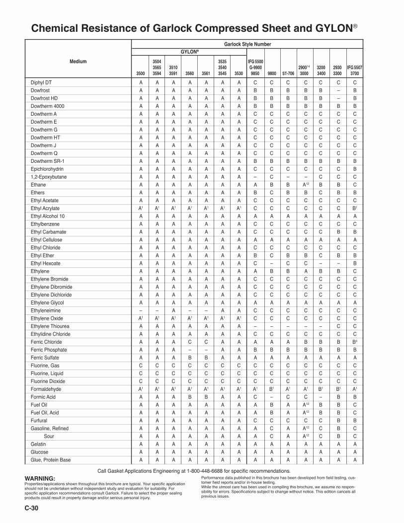
Diphyl DT A A A A A A A C C C C C C CDowfrost A A A A A A A B B B B B – BDowfrost HD A A A A A A A B B B B B – BDowtherm 4000 A A A A A A A B B B B B B BDowtherm A A A A A A A A C C C C C C CDowtherm E A A A A A A A C C C C C C CDowtherm G A A A A A A A C C C C C C CDowtherm HT A A A A A A A C C C C C C CDowtherm J A A A A A A A C C C C C C CDowtherm Q A A A A A A A C C C C C C CDowtherm SR-1 A A A A A A A B B B B B B BEpichlorohydrin A A A A A A A C C C C C C B1,2-Epoxybutane A A A A A A A – C – – C C CEthane A A A A A A A A B B A12 B B CEthers A A A A A A A B C B B C B BEthyl Acetate A A A A A A A C C C C C C CEthyl Acrylate A1 A1 A1 A1 A1 A1 A1 C C C C C C B1
Ethyl Alcohol 10 A A A A A A A A A A A A A AEthylbenzene A A A A A A A C C C C C C CEthyl Carbamate A A A A A A A C C C C C B BEthyl Cellulose A A A A A A A A A A A A A AEthyl Chloride A A A A A A A C C C C C C CEthyl Ether A A A A A A A B C B B C B BEthyl Hexoate A A A A A A A C – C C – – BEthylene A A A A A A A A B B A B B CEthylene Bromide A A A A A A A C C C C C C CEthylene Dibromide A A A A A A A C C C C C C CEthylene Dichloride A A A A A A A C C C C C C CEthylene Glycol A A A A A A A A A A A A A AEthyleneimine – – A – – A A C C C C C C CEthylene Oxide A1 A1 A1 A1 A1 A1 A1 C C C C C C CEthylene Thiourea A A A A A A A – – – – – C CEthylidine Chloride A A A A A A A C C C C C C CFerric Chloride A A A C C A A A A A B B B B4
Ferric Phosphate A A A – – A A B B B B B B BFerric Sulfate A A A B B A A A A A A A A AFluorine, Gas C C C C C C C C C C C C C CFluorine, Liquid C C C C C C C C C C C C C CFluorine Dioxide C C C C C C C C C C C C C CFormaldehyde A1 A1 A1 A1 A1 A1 A1 A1 B1 A1 A1 B1 B1 A1
Formic Acid A A A B B A A C – C C – B BFuel Oil A A A A A A A A B A A12 B B CFuel Oil, Acid A A A A A A A A B A A12 B B CFurfural A A A A A A A C C C C C B BGasoline, Refined A A A A A A A A C A A12 C B C Sour A A A A A A A A C A A12 C B CGelatin A A A A A A A A A A A A A AGlucose A A A A A A A A A A A A A AGlue, Protein Base A A A A A A A A A A A A A A
C-30
Chemical Resistance of Garlock Compressed Sheet and GYLON®
WARNING:Properties/applications shown throughout this brochure are typical. Your specific application should not be undertaken without independent study and evaluation for suitability. For specific application recommendations consult Garlock. Failure to select the proper sealing products could result in property damage and/or serious personal injury.
Performance data published in this brochure has been developed from field testing, cus-tomer field reports and/or in-house testing. While the utmost care has been used in compiling this brochure, we assume no respon-sibility for errors. Specifications subject to change without notice. This edition cancels all previous issues.
Call Gasket Applications Engineering at 1-800-448-6688 for specific recommendations.
Garlock Style Number
GYLON®
Medium 3504 3535 IFG 5500 3565 3510 3540 G-9900 290014 3200 2930 IFG 5507 3500 3594 3591 3560 3561 3545 3530 9850 9800 ST-706 3000 3400 3300 3700
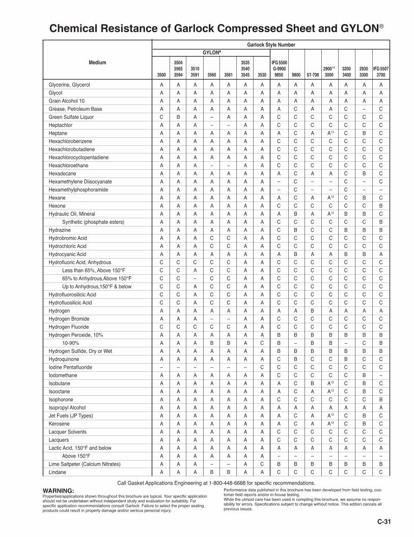
Glycerine, Glycerol A A A A A A A A A A A A A AGlycol A A A A A A A A A A A A A AGrain Alcohol 10 A A A A A A A A A A A A A AGrease, Petroleum Base A A A A A A A A C A A C – CGreen Sulfate Liquor C B A – A A A C C C C C C CHeptachlor A A A – – A A C C C C C C CHeptane A A A A A A A A C A A12 C B CHexachlorobenzene A A A A A A A C C C C C C CHexachlorobutadiene A A A A A A A C C C C C C CHexachlorocyclopentadiene A A A A A A A C C C C C C CHexachloroethane A A A – – A A C C C C C C CHexadecane A A A A A A A A C A A C B CHexamethylene Diisocyanate A A A A A A A – C – – C – CHexamethylphosphoramide A A A A A A A – C – – C – –Hexane A A A A A A A A C A A12 C B CHexone A A A A A A A C C C C C C BHydraulic Oil, Mineral A A A A A A A A B A A12 B B C Synthetic (phosphate esters) A A A A A A A C C C C C C BHydrazine A A A A A A A C B C C B B BHydrobromic Acid A A A C C A A C C C C C C CHydrochloric Acid A A A C C A A C C C C C C CHydrocyanic Acid A A A A A A A A B A A B B AHydrofluoric Acid, Anhydrous C C C C C A A C C C C C C C Less than 65%, Above 150°F C C A C C A A C C C C C C C 65% to Anhydrous,Above 150°F C C – C C A A C C C C C C C Up to Anhydrous,150°F & below C C A C C A A C C C C C C CHydrofluorosilicic Acid C C A C C A A C C C C C C CHydrofluosilicic Acid C C A C C A A C C C C C C CHydrogen A A A A A A A A A B A A A AHydrogen Bromide A A A – – A A C C C C C C CHydrogen Fluoride C C C C C A A C C C C C C CHydrogen Peroxide, 10% A A A A A A A B B B B B B B 10-90% A A A B B A C B – B B – C BHydrogen Sulfide, Dry or Wet A A A A A A A B B B B B B BHydroquinone A A A A A A A C B C C B C CIodine Pentafluoride – – – – – – C C C C C C C CIodomethane A A A A A A A C C C C C B –Isobutane A A A A A A A A C B A12 C B CIsooctane A A A A A A A A C A A12 C B CIsophorone A A A A A A A C C C C C C BIsopropyl Alcohol A A A A A A A A A A A A A AJet Fuels (JP Types) A A A A A A A A C A A12 C B CKerosene A A A A A A A A C A A12 C B CLacquer Solvents A A A A A A A C C C C C C CLacquers A A A A A A A C C C C C C CLactic Acid, 150°F and below A A A A A A A A A A A A A A Above 150°F A A A A A A A – – – – – – –Lime Saltpeter (Calcium Nitrates) A A A – – A C B B B B B B BLindane A A A B B A A C C C C C C C
C-31
Chemical Resistance of Garlock Compressed Sheet and GYLON®
WARNING:Properties/applications shown throughout this brochure are typical. Your specific application should not be undertaken without independent study and evaluation for suitability. For specific application recommendations consult Garlock. Failure to select the proper sealing products could result in property damage and/or serious personal injury.
Performance data published in this brochure has been developed from field testing, cus-tomer field reports and/or in-house testing. While the utmost care has been used in compiling this brochure, we assume no respon-sibility for errors. Specifications subject to change without notice. This edition cancels all previous issues.
Call Gasket Applications Engineering at 1-800-448-6688 for specific recommendations.
Garlock Style Number
GYLON®
Medium 3504 3535 IFG 5500 3565 3510 3540 G-9900 290014 3200 2930 IFG 5507 3500 3594 3591 3560 3561 3545 3530 9850 9800 ST-706 3000 3400 3300 3700

C-32
Linseed Oil A A A A A A A A B A A B A BLiquified Petroleum Gas (LPG) A A A A A A A A B C A12 B B CLithium Bromide A A A A A A A A – A A – A ALithium, Elemental C C C C C C C C C C C C C CLubricating Oils, Refined A A A A A A A A B A A12 B B C Mineral or Petroleum Types A A A A A A A A B A A12 B B C Sour A A A A A A A B B B B B B CLye C B A6 C A6 A11 A6 C C C C C C CMagnesium Chloride A A A B B A A A A A A A A AMagnesium Hydroxide A A A A A A A B B B B B B BMagnesium Sulfate A A A A A A A A A A A A A AMaleic Acid A A A A A A A B B B B B B AMaleic Anhydride A A A A A A A C – C C – C CMercuric Chloride A A A C C A A A A A A A B AMercury A A A A A A A A A A A A A AMethane A A A A A A A A B B A C B CMethanol, Methyl Alcohol A A A A A A A A A A A A A AMethoxychlor A A A A A A A C C C C C C CMethylacrylic Acid A A A – – A A C C C C C C CMethyl Alcohol A A A A A A A A A A A A A A2-Methylaziridine – – A – – A A C C C C C C CMethyl Bromide A A A A A A A C C C C C C CMethyl Chloride A A A B B A A C C C C C C CMethyl Chloroform A A A A A A A C C C C C C C4,4 Methylene Bis(2-chloroaniline) A A A – – A A C C C C C C CMethylene Chloride A A A A A A A C C C C C C C4,4-Methylene Dianiline A A A A A A A C C C C C C –Methylene Diphenyldiisocyanate A A A – – A A C C C C C C –Methyl Ethyl Ketone A A A A A A A C C C C C C CMethyl Hydrazine A A A A A A A C B C C B B BMethyl Iodide A A A A A A A C C C C C B –Methyl Isobutyl Ketone (MIBK) A A A A A A A C C C C C C BMethyl Isocyanate A A A A A A A – C - – C – –Methyl Methacrylate A1 A1 A1 A1 A1 A1 A1 C C C C C C CN-Methyl-2-Pyrrolidone A A A A A A A C B C C B – –Methyl Tert. Butyl Ether (MTBE) A A A A A A A B C B B B C CMilk 10 A A A A A A A A A A A A A A Mineral Oils A A A A A A A A B A A12 B B CMobiltherm 600 A A A A A A A A C A A C – CMobiltherm 603 A A A A A A A A C A A C – CMobiltherm 605 A A A A A A A A C A A C – CMobiltherm Light A A A A A A A C C C C C C CMolten Alkali Metals C C C C C C C C C C C C C CMonomethylamine A A A A A A A C B C C B A BMultiTherm 100 A A A A A A A A C A A C B CMultiTherm 503 A A A A A A A A C A A C – CMultiTherm IG-2 A A A A A A A A C A A C B CMultiTherm PG-1 A A A A A A A A C A A C B CMuriatic Acid A A A C C A A C C C C C C C
Chemical Resistance of Garlock Compressed Sheet and GYLON®
WARNING:Properties/applications shown throughout this brochure are typical. Your specific application should not be undertaken without independent study and evaluation for suitability. For specific application recommendations consult Garlock. Failure to select the proper sealing products could result in property damage and/or serious personal injury.
Performance data published in this brochure has been developed from field testing, cus-tomer field reports and/or in-house testing. While the utmost care has been used in compiling this brochure, we assume no respon-sibility for errors. Specifications subject to change without notice. This edition cancels all previous issues.
Call Gasket Applications Engineering at 1-800-448-6688 for specific recommendations.
Garlock Style Number
GYLON®
Medium 3504 3535 IFG 5500 3565 3510 3540 G-9900 290014 3200 2930 IFG 5507 3500 3594 3591 3560 3561 3545 3530 9850 9800 ST-706 3000 3400 3300 3700
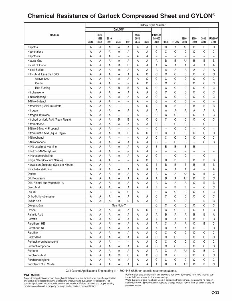
C-33
Chemical Resistance of Garlock Compressed Sheet and GYLON®
WARNING:Properties/applications shown throughout this brochure are typical. Your specific application should not be undertaken without independent study and evaluation for suitability. For specific application recommendations consult Garlock. Failure to select the proper sealing products could result in property damage and/or serious personal injury.
Performance data published in this brochure has been developed from field testing, cus-tomer field reports and/or in-house testing. While the utmost care has been used in compiling this brochure, we assume no respon-sibility for errors. Specifications subject to change without notice. This edition cancels all previous issues.
Call Gasket Applications Engineering at 1-800-448-6688 for specific recommendations.
Garlock Style Number
GYLON®
Medium 3504 3535 IFG 5500 3565 3510 3540 G-9900 290014 3200 2930 IFG 5507 3500 3594 3591 3560 3561 3545 3530 9850 9800 ST-706 3000 3400 3300 3700
Naphtha A A A A A A A A C A A12 C B CNaphthalene A A A A A A A C C C C C C CNaphthols A A A – – A A – – – – – – –Natural Gas A A A A A A A A B B A12 B B BNickel Chloride A A A B B A A A A A A A A ANickel Sulfate A A A A A A A A A A A A A ANitric Acid, Less than 30% A A A A A A C C C C C C C C Above 30% A A A A A A C C C C C C C C Crude A A A – – A C C C C C C C C Red Fuming A A A B B A C C C C C C C CNitrobenzene A A A A A A A C C C C C C C4-Nitrobiphenyl A A A A A A A C C C C C C C2-Nitro-Butanol A A A – – A – C – C C – C –Nitrocalcite (Calcium Nitrate) A A A – – A C B B B B B B BNitrogen A A A A A A A A A A A A A ANitrogen Tetroxide A A A – – A – C C C C C C CNitrohydrochloric Acid (Aqua Regia) A A A B B A C C C C C C C CNitromethane A A A A A A A C – C C – C –2-Nitro-2-Methyl Propanol A A A – – A – C – C C – C –Nitromuriatic Acid (Aqua Regia) A A A B B A C C C C C C C C4-Nitrophenol A A A – – A A C C C C C C C2-Nitropropane A A A A A A A C – C C – C CN-Nitrosodimethylamine A A A A A A A B B B B B – –N-Nitroso-N-Methylurea A A A – – A A – – – – – – –N-Nitrosomorpholine A A A A A A A C – C C – C –Norge Niter (Calcium Nitrate) A A A – – A C B B B B B B BNorwegian Saltpeter (Calcium Nitrate) A A A – – A C B B B B B B BN-Octadecyl Alcohol A A A A A A A A A A A A – AOctane A A A A A A A A C A A12 C B COil, Petroleum A A A A A A A A B A A12 B B COils, Animal and Vegetable 10 A A A A A A A A C A A C B BOleic Acid A A A A A A A B – B B – C COleum A – C C C A – C C C C C C COrthodichlorobenzene A A A A A A A C C C C C C COxalic Acid A A A B B A A C – C C – B BOxygen, Gas See Note 7 C C C C C C COzone A A A A A A C C C C C C C CPalmitic Acid A A A A A A A A B A A B B AParaffin A A A A A A A A B A A B B CParatherm HE A A A A A A A A C A A C B CParatherm NF A A A A A A A A C A A C – CParathion A A A A A A A C C C C C C CParaxylene A A A A A A A C C C C C C CPentachloronitrobenzene A A A – – A A C C C C C C CPentachlorophenol A A A A A A A C C C C C C CPentane A A A A A A A A C A A12 C B CPerchloric Acid A A A C C A C C C C C C C CPerchloroethylene A A A A A A A C C C C C C CPetroleum Oils, Crude A A A A A A A A B A A12 B B C
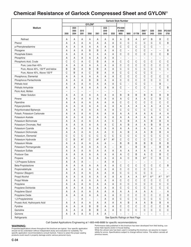
Chemical Resistance of Garlock Compressed Sheet and GYLON®
WARNING:Properties/applications shown throughout this brochure are typical. Your specific application should not be undertaken without independent study and evaluation for suitability. For specific application recommendations consult Garlock. Failure to select the proper sealing products could result in property damage and/or serious personal injury.
Performance data published in this brochure has been developed from field testing, cus-tomer field reports and/or in-house testing. While the utmost care has been used in compiling this brochure, we assume no respon-sibility for errors. Specifications subject to change without notice. This edition cancels all previous issues.
Call Gasket Applications Engineering at 1-800-448-6688 for specific recommendations.
Garlock Style Number
GYLON® Medium 3504 3535 IFG 5500 3565 3510 3540 G-9900 290014 3200 2930 IFG 5507 3500 3594 3591 3560 3561 3545 3530 9850 9800 ST-706 3000 3400 3300 3700
Refined A A A A A A A A B A A12 B B CPhenol A A A A A A A C C C C C C Bp-Phenylenediamine A A A A A A A C C C C C – –Phosgene A A A B B A A C – C C – – BPhosphate Esters A A A A A A A C C C C C C BPhosphine A A A A A A A – – – – – – –Phosphoric Acid, Crude C C A C B A A C C C C C C C Pure, Less than 45% A A A A A A A C C C C C C C Pure, Above 45%, 150°F and below B B A B B A A C C C C C C C Pure, Above 45%, Above 150°F C B A C B A A C C C C C – –Phosphorus, Elemental A A A A A A A C C C C C C CPhosphorus Pentachloride A A A B B A A C C C C C C CPhthalic Acid A A A A A A A C – C C – B –Phthalic Anhydride A A A A A A A C – C C – C BPicric Acid, Molten – – – – – – – – – – – – – – Water Solution A A A A A A A B B B B B B BPinene A A A A A A A A C A A C B CPiperidine A A A A A A A C C C C C C CPolyacrylonitrile A A A A A A A A A A A A A APolychlorinated Biphenyls A A A A A A A C C C C C C CPotash, Potassium Carbonate A A A A A A A A A A A A A APotassium Acetate A A A A A A A A A A A A A APotassium Bichromate A A A A A A C A B A A B B APotassium Chromate, Red A A A A A A C A B A A B B APotassium Cyanide A A A A A A A A A A A A A APotassium Dichromate A A A A A A C A B A A B B APotassium, Elemental C C C C C C C C C C C C C CPotassium Hydroxide C B A6 C A6 A11 A6 C C C C C C CPotassium Nitrate A A A A A A – B B B B B B BPotassium Permanganate A A A A A A – B – B B – B BPotassium Sulfate A A A A A A A A A A A A A AProducer Gas A A A A A A A A C B A C B CPropane A A A A A A A A C B A12 C B C1,3-Propane Sultone A A A – – A A – – – – – – –Beta-Propiolactone A A A A A A A C C C C C C BPropionaldehyde A A A A A A A C C C C C – –Propoxur (Baygon) A A A A A A A C C C C C – –Propyl Alcohol A A A A A A A A A A A12 A12 A12 A12
Propyl Nitrate A A A A A A A C C C C C C CPropylene A A A A A A A C C C C C C CPropylene Dichloride A A A A A A A C C C C C C CPropylene Glycol A A A A A A A A A A A A - APropylene Oxide A A A A A A A C C C C C C B1,2-Propylenimine – – A – – A A C C C C C C CPrussic Acid, Hydrocyanic Acid A A A A A A A A B A A B B APyridine A A A B B A A C C C C C C BQuinoline A A A B B A A C C C C C C CQuinone A A A A A A – – – – – – – –Refrigerants See Specific Ratings on Next Page
C-34
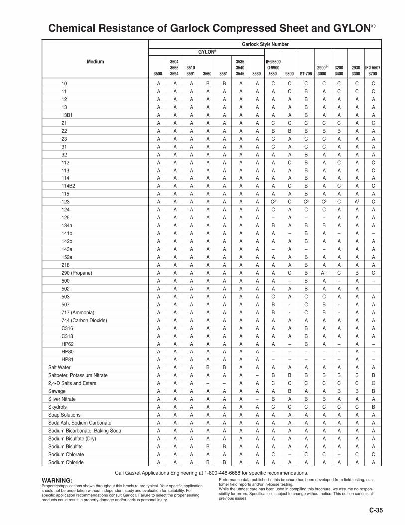
Chemical Resistance of Garlock Compressed Sheet and GYLON®
WARNING:Properties/applications shown throughout this brochure are typical. Your specific application should not be undertaken without independent study and evaluation for suitability. For specific application recommendations consult Garlock. Failure to select the proper sealing products could result in property damage and/or serious personal injury.
Performance data published in this brochure has been developed from field testing, cus-tomer field reports and/or in-house testing. While the utmost care has been used in compiling this brochure, we assume no respon-sibility for errors. Specifications subject to change without notice. This edition cancels all previous issues.
Call Gasket Applications Engineering at 1-800-448-6688 for specific recommendations.
Garlock Style Number
GYLON®
Medium 3504 3535 IFG 5500 3565 3510 3540 G-9900 290014 3200 2930 IFG 5507 3500 3594 3591 3560 3561 3545 3530 9850 9800 ST-706 3000 3400 3300 3700
10 A A A B B A A C C C C C C C 11 A A A A A A A A C B A C C C 12 A A A A A A A A A B A A A A 13 A A A A A A A A A B A A A A 13B1 A A A A A A A A A B A A A A 21 A A A A A A A C C C C C A C 22 A A A A A A A B B B B B A A 23 A A A A A A A C A C C A A A 31 A A A A A A A C A C C A A A 32 A A A A A A A A A B A A A A 112 A A A A A A A A C B A C A C 113 A A A A A A A A A B A A A C 114 A A A A A A A A A B A A A A 114B2 A A A A A A A A C B A C A C 115 A A A A A A A A A B A A A A 123 A A A A A A A C3 C C3 C3 C A3 C 124 A A A A A A A C A C C A A A 125 A A A A A A A – A – – A A A 134a A A A A A A A B A B B A A A 141b A A A A A A A A – B A – A – 142b A A A A A A A A A B A A A A 143a A A A A A A A – A – – A A A 152a A A A A A A A A A B A A A A 218 A A A A A A A A A B A A A A 290 (Propane) A A A A A A A A C B A12 C B C 500 A A A A A A A A – B A – A – 502 A A A A A A A A A B A A A – 503 A A A A A A A C A C C A A A 507 A A A A A A A B - C B - A A 717 (Ammonia) A A A A A A A B - C B - A A 744 (Carbon Dioxide) A A A A A A A A A A A A A A C316 A A A A A A A A A B A A A A C318 A A A A A A A A A B A A A A HP62 A A A A A A A A – B A – A – HP80 A A A A A A A – – – – – A – HP81 A A A A A A A – – – – – A –Salt Water A A A B B A A A A A A A A ASaltpeter, Potassium Nitrate A A A A A A – B B B B B B B2,4-D Salts and Esters A A A – – A A C C C C C C CSewage A A A A A A A A B A A B B BSilver Nitrate A A A A A A – B A B B A A A Skydrols A A A A A A A C C C C C C BSoap Solutions A A A A A A A A A A A A A ASoda Ash, Sodium Carbonate A A A A A A A A A A A A A ASodium Bicarbonate, Baking Soda A A A A A A A A A A A A A ASodium Bisulfate (Dry) A A A A A A A A A A A A A ASodium Bisulfite A A A B B A A A A A A A A ASodium Chlorate A A A A A A A C – C C – C CSodium Chloride A A A B B A A A A A A A A A
C-35
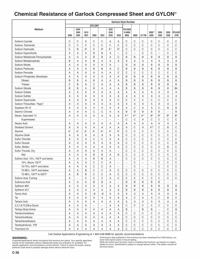
Chemical Resistance of Garlock Compressed Sheet and GYLON®
WARNING:Properties/applications shown throughout this brochure are typical. Your specific application should not be undertaken without independent study and evaluation for suitability. For specific application recommendations consult Garlock. Failure to select the proper sealing products could result in property damage and/or serious personal injury.
Performance data published in this brochure has been developed from field testing, cus-tomer field reports and/or in-house testing. While the utmost care has been used in compiling this brochure, we assume no respon-sibility for errors. Specifications subject to change without notice. This edition cancels all previous issues.
Call Gasket Applications Engineering at 1-800-448-6688 for specific recommendations.
Garlock Style Number
GYLON® Medium 3504 3535 IFG 5500 3565 3510 3540 G-9900 290014 3200 2930 IFG 5507 3500 3594 3591 3560 3561 3545 3530 9850 9800 ST-706 3000 3400 3300 3700
Sodium Cyanide C C A C C A A C C C C C C CSodium, Elemental C C C C C C C C C C C C C CSodium Hydroxide C B A6 C A6 A11 A6 C C C C C C CSodium Hypochlorite A A A B B A – C – C C – C CSodium Metaborate Peroxyhydrate A A A B B A C B B B B B B BSodium Metaphosphate B A A B A A A A A A A A A ASodium Nitrate A A A A A A – B B B B B B BSodium Perborate A A A B B A C B B B B B B BSodium Peroxide A A A A A A C C C C C C C CSodium Phosphate, Monobasic A A A A A A A B B B B B B B Dibasic B B A B A A A B B B B B B B Tribasic C B A C A A A B B B B B B BSodium Silicate B B A B A A A B B B B B B B4Sodium Sulfate A A A A A A A A A A A A A ASodium Sulfide A A A A A A A A A A A A A ASodium Superoxide A A A A A A C C C C C C C CSodium Thiosulfate, “Hypo” A A A A A A A A A A A A A ASoybean Oil 10 A A A A A A A A C A A C B BStannic Chloride A A A C C A A B B B B B – BSteam, Saturated 13 A A A A A A A A13 A13 A13 B9 B9 B9 B9
Superheated – – – – – – – C C A C C C CStearic Acid A A A A A A A A A A A A A AStoddard Solvent A A A A A A A A C A A12 C B CStyrene A1 A1 A1 A1 A1 A1 A1 C C C C C C CStyrene Oxide A A A A A A A C C C C C C CSulfur Chloride A A A C C A A C C C C C C CSulfur Dioxide A A A A A A A C C C C C C BSulfur, Molten A A A A A A A C C C C C B CSulfur Trioxide, Dry A A A A A A – C C C C C C C Wet A A A B B A B C C C C C C CSulfuric Acid, 10%, 150°F and below A A A B B A – C C C C C C C 10%, Above 150°F A A A C C A – – C – – C C C 10-75%, 500°F and below A A A C C A – – C – – C C C 75-98%, 150°F and below A A B C C A C C C C C C C C 75-98%, 150°F to 500°F A B B C C A C C C C C C C CSulfuric Acid, Fuming A – C C C A C C C C C C C CSulfurous Acid A A A B B A – B B B B B – –Syltherm 800 A A A A A A A B B B B B B BSyltherm XLT A A A A A A A B B B B B B BTannic Acid A A A –8 –8 A A A A A A A A ATar A A A A A A A A C A A C B CTartaric Acid A A A A A A A A A A A A A A2,3,7,8-TCDB-p-Dioxin A A A – – A A C C C C C C CTertiary Butyl Amine A A A A A A A B – B B – C BTetrabromoethane A A A A A A A C C C C C C CTetrachlorethane A A A A A A A C C C C C C CTetrachloroethylene A A A A A A A C C C C C C CTetrahydrofuran, THF A A A A A A A C C C C C C CTherminol 44 A A A A A A A C C C C C C C
C-36
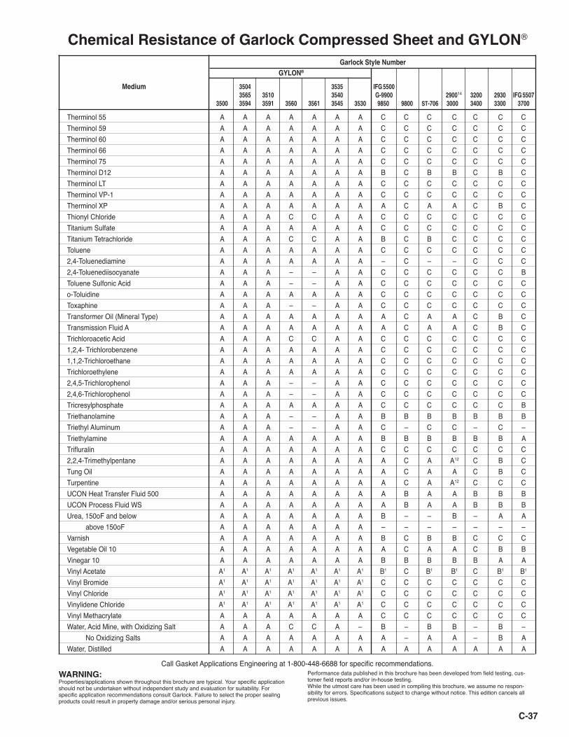
Chemical Resistance of Garlock Compressed Sheet and GYLON®
WARNING:Properties/applications shown throughout this brochure are typical. Your specific application should not be undertaken without independent study and evaluation for suitability. For specific application recommendations consult Garlock. Failure to select the proper sealing products could result in property damage and/or serious personal injury.
Performance data published in this brochure has been developed from field testing, cus-tomer field reports and/or in-house testing. While the utmost care has been used in compiling this brochure, we assume no respon-sibility for errors. Specifications subject to change without notice. This edition cancels all previous issues.
Call Gasket Applications Engineering at 1-800-448-6688 for specific recommendations.
Garlock Style Number
GYLON®
Medium 3504 3535 IFG 5500 3565 3510 3540 G-9900 290014 3200 2930 IFG 5507 3500 3594 3591 3560 3561 3545 3530 9850 9800 ST-706 3000 3400 3300 3700
C-37
Therminol 55 A A A A A A A C C C C C C CTherminol 59 A A A A A A A C C C C C C CTherminol 60 A A A A A A A C C C C C C CTherminol 66 A A A A A A A C C C C C C CTherminol 75 A A A A A A A C C C C C C CTherminol D12 A A A A A A A B C B B C B CTherminol LT A A A A A A A C C C C C C CTherminol VP-1 A A A A A A A C C C C C C CTherminol XP A A A A A A A A C A A C B CThionyl Chloride A A A C C A A C C C C C C CTitanium Sulfate A A A A A A A C C C C C C CTitanium Tetrachloride A A A C C A A B C B C C C CToluene A A A A A A A C C C C C C C2,4-Toluenediamine A A A A A A A – C – – C C C2,4-Toluenediisocyanate A A A – – A A C C C C C C BToluene Sulfonic Acid A A A – – A A C C C C C C Co-Toluidine A A A A A A A C C C C C C CToxaphine A A A – – A A C C C C C C CTransformer Oil (Mineral Type) A A A A A A A A C A A C B CTransmission Fluid A A A A A A A A A C A A C B CTrichloroacetic Acid A A A C C A A C C C C C C C1,2,4- Trichlorobenzene A A A A A A A C C C C C C C1,1,2-Trichloroethane A A A A A A A C C C C C C CTrichloroethylene A A A A A A A C C C C C C C2,4,5-Trichlorophenol A A A – – A A C C C C C C C2,4,6-Trichlorophenol A A A – – A A C C C C C C CTricresylphosphate A A A A A A A C C C C C C BTriethanolamine A A A – – A A B B B B B B BTriethyl Aluminum A A A – – A A C – C C – C –Triethylamine A A A A A A A B B B B B B ATrifluralin A A A A A A A C C C C C C C2,2,4-Trimethylpentane A A A A A A A A C A A12 C B CTung Oil A A A A A A A A C A A C B CTurpentine A A A A A A A A C A A12 C C CUCON Heat Transfer Fluid 500 A A A A A A A A B A A B B BUCON Process Fluid WS A A A A A A A A B A A B B BUrea, 150oF and below A A A A A A A B – – B – A A above 150oF A A A A A A A – – – – – – –Varnish A A A A A A A B C B B C C CVegetable Oil 10 A A A A A A A A C A A C B BVinegar 10 A A A A A A A B B B B B A AVinyl Acetate A1 A1 A1 A1 A1 A1 A1 B1 C B1 B1 C B1 B1
Vinyl Bromide A1 A1 A1 A1 A1 A1 A1 C C C C C C CVinyl Chloride A1 A1 A1 A1 A1 A1 A1 C C C C C C CVinylidene Chloride A1 A1 A1 A1 A1 A1 A1 C C C C C C CVinyl Methacrylate A A A A A A A C C C C C C CWater, Acid Mine, with Oxidizing Salt A A A C C A – B – B B – B – No Oxidizing Salts A A A A A A A A – A A – B AWater, Distilled A A A A A A A A A A A A A A
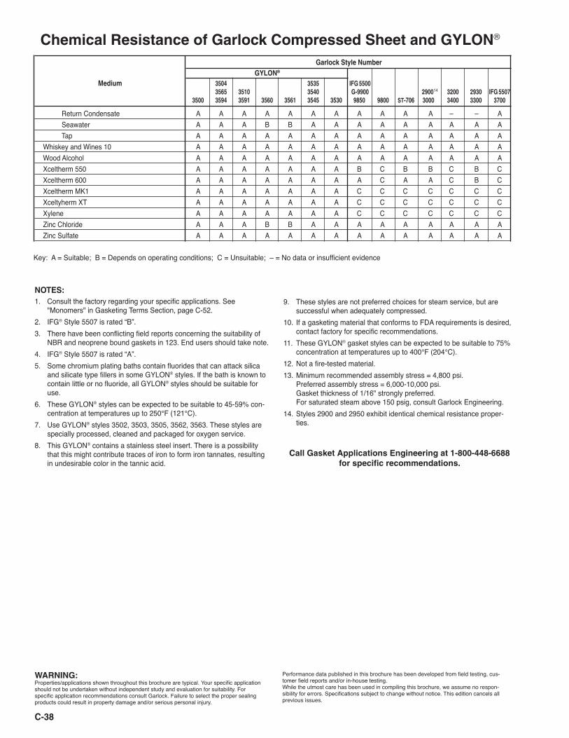
Chemical Resistance of Garlock Compressed Sheet and GYLON®
WARNING:Properties/applications shown throughout this brochure are typical. Your specific application should not be undertaken without independent study and evaluation for suitability. For specific application recommendations consult Garlock. Failure to select the proper sealing products could result in property damage and/or serious personal injury.
Performance data published in this brochure has been developed from field testing, cus-tomer field reports and/or in-house testing. While the utmost care has been used in compiling this brochure, we assume no respon-sibility for errors. Specifications subject to change without notice. This edition cancels all previous issues.
Call Gasket Applications Engineering at 1-800-448-6688 for specific recommendations.
Garlock Style Number
GYLON® Medium 3504 3535 IFG 5500 3565 3510 3540 G-9900 290014 3200 2930 IFG 5507 3500 3594 3591 3560 3561 3545 3530 9850 9800 ST-706 3000 3400 3300 3700
C-38
Return Condensate A A A A A A A A A A A – – A Seawater A A A B B A A A A A A A A A Tap A A A A A A A A A A A A A AWhiskey and Wines 10 A A A A A A A A A A A A A AWood Alcohol A A A A A A A A A A A A A AXceltherm 550 A A A A A A A B C B B C B CXceltherm 600 A A A A A A A A C A A C B CXceltherm MK1 A A A A A A A C C C C C C CXceltyherm XT A A A A A A A C C C C C C CXylene A A A A A A A C C C C C C CZinc Chloride A A A B B A A A A A A A A AZinc Sulfate A A A A A A A A A A A A A A
Key: A = Suitable; B = Depends on operating conditions; C = Unsuitable; – = No data or insufficient evidence
NOTES:1. Consult the factory regarding your specific applications. See
"Monomers" in Gasketing Terms Section, page C-52.2. IFG® Style 5507 is rated “B”.3. There have been conflicting field reports concerning the suitability of
NBR and neoprene bound gaskets in 123. End users should take note.4. IFG® Style 5507 is rated “A”.5. Some chromium plating baths contain fluorides that can attack silica
and silicate type fillers in some GYLON® styles. If the bath is known to contain little or no fluoride, all GYLON® styles should be suitable for use.
6. These GYLON® styles can be expected to be suitable to 45-59% con-centration at temperatures up to 250°F (121°C).
7. Use GYLON® styles 3502, 3503, 3505, 3562, 3563. These styles are specially processed, cleaned and packaged for oxygen service.
8. This GYLON® contains a stainless steel insert. There is a possibility that this might contribute traces of iron to form iron tannates, resulting in undesirable color in the tannic acid.
9. These styles are not preferred choices for steam service, but are successful when adequately compressed.
10. If a gasketing material that conforms to FDA requirements is desired, contact factory for specific recommendations.
11. These GYLON® gasket styles can be expected to be suitable to 75% concentration at temperatures up to 400°F (204°C).
12. Not a fire-tested material.13. Minimum recommended assembly stress = 4,800 psi.
Preferred assembly stress = 6,000-10,000 psi. Gasket thickness of 1/16" strongly preferred. For saturated steam above 150 psig, consult Garlock Engineering.
14. Styles 2900 and 2950 exhibit identical chemical resistance proper-ties.
Call Gasket Applications Engineering at 1-800-448-6688 for specific recommendations.
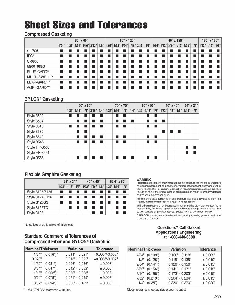
C-39
60" x 60" 60" x 120" 60" x 180" 150" x 150" 1/64" 1/32" 3/64" 1/16" 3/32" 1/8" 1/64" 1/32" 3/64" 1/16" 3/32" 1/8" 1/64" 1/32" 3/64" 1/16" 3/32" 1/8" 1/32" 1/16" 1/8"
ST-706 ■ ■ ■ ■ ■ ■ ■ ■ ■ ■ ■ ■ ■ ■ ■ ■ ■ ■ ■ ■ ■
IFG® ■ ■ ■ ■ ■ ■ ■ ■ ■ ■ ■ ■ ■ ■ ■ ■ ■ ■ ■ ■ ■
G-9900 ■ ■ ■ ■ ■ ■ ■ ■ ■ ■ ■ ■ ■ ■ ■ ■ ■ ■ ■ ■ ■
9800 / 9850 ■ ■ ■ ■ ■ ■ ■ ■ ■ ■ ■ ■ ■ ■ ■ ■ ■ ■ ■ ■ ■
BLUE-GARD® ■ ■ ■ ■ ■ ■ ■ ■ ■ ■ ■ ■ ■ ■ ■ ■ ■ ■ ■ ■ ■
MULTI-SWELL™ ■ ■ ■ ■ ■ ■ ■ ■ ■ ■ ■ ■ ■ ■ ■ ■ ■ ■ ■ ■ ■
LEAK-GARD™ ■ ■ ■ ■ ■ ■ ■ ■ ■ ■ ■ ■ ■ ■ ■ ■ ■ ■ ■ ■ ■
AGRI-GARD™ ■ ■ ■ ■ ■ ■ ■ ■ ■ ■ ■ ■ ■ ■ ■ ■ ■ ■ ■ ■ ■
Sheet Sizes and TolerancesCompressed Gasketing
Flexible Graphite Gasketing
Note: Tolerance is ±10% of thickness.
24" x 24" 40" x 40" 59.4" x 60" 1/32" 1/16" 1/8" 1/32" 1/16" 1/8" 1/32" 1/16" 1/8"
Style 3123/3125 ■ ■ ■ ■ ■ ■ ■ ■ ■
Style 3124/3126 ■ ■ ■ ■ ■ ■ ■ ■ ■
Style 3125SS ■ ■ ■ ■ ■ ■ ■ ■ ■
Style 3125TC ■ ■ ■ ■ ■ ■ ■
Style 3128 ■ ■ ■ ■
Standard Commercial Tolerances of Compressed Fiber and GYLON® Gasketing Nominal Thickness Variation Tolerance 1/64" (0.016")* 0.014" - 0.021" +0.005"/-0.002" 0.020" 0.018" - 0.025" +0.005"/-0.002" 1/32" (0.031") 0.026" - 0.036" ± 0.005" 3/64" (0.047") 0.042" - 0.052" ± 0.005" 1/16" (0.062") 0.056" - 0.068" ± 0.006" 5/64" (0.078") 0.071" - 0.085" ± 0.007" 3/32" (0.094") 0.086" - 0.102" ± 0.008"* 1/64" GYLON® tolerance = ±0.005"
GYLON® Gasketing 60" x 60" 70" x 70" 60" x 90" 40" x 40" 24" x 24" 1/32" 1/16" 1/8" 3/16" 1/4" 1/32" 1/16" 1/8" 1/4" 1/32" 1/16" 1/8" 1/32" 1/16" 1/8" 1/16" 1/8"
Style 3500 ■ ■ ■ ■ ■ ■ ■ ■ ■
Style 3504 ■ ■ ■ ■ ■ ■ ■ ■ ■ ■
Style 3510 ■ ■ ■ ■ ■ ■ ■ ■ ■
Style 3530 ■ ■ ■ ■ ■ Style 3540 ■ ■ ■ ■ ■ ■ ■ ■
Style 3545 ■ ■ ■ ■ ■ ■ ■ ■
Style HP-3560 ■ ■
Style HP-3561 ■ ■
Style 3565 ■ ■ ■ ■ ■ ■ ■ ■ ■
Nominal Thickness Variation Tolerance
Questions? Call Gasket Applications Engineering
at 1-800-448-6688
WARNING:Properties/applications shown throughout this brochure are typical. Your specific application should not be undertaken without independent study and evalua-tion for suitability. For specific application recommendations consult Garlock. Failure to select the proper sealing products could result in property damage and/or serious personal injury. Performance data published in this brochure has been developed from field testing, customer field reports and/or in-house testing. While the utmost care has been used in compiling this brochure, we assume no responsibility for errors. Specifications subject to change without notice. This edition cancels all previous issues. Subject to change without notice. GARLOCK is a registered trademark for packings, seals, gaskets, and other products of Garlock.
7/64" (0.109") 0.100" - 0.118" ± 0.009" 1/8" (0.125") 0.115" - 0.135" ± 0.010" 9/64" (0.141") 0.126" - 0.156" ± 0.015" 5/32" (0.156") 0.141" - 0.171" ± 0.015" 3/16" (0.188") 0.173" - 0.203" ± 0.015" 7/32" (0.219") 0.204" - 0.234" ± 0.015" 1/4" (0.25") 0.230" - 0.270" ± 0.020"Close tolerance sheet available upon request.
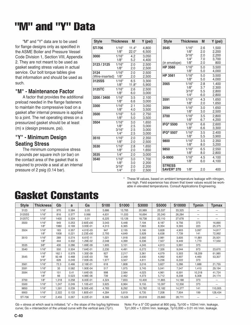
C-40
"M" and "Y" Data
ST-706 1/16" 11.4* 4,800 1/8" 22.0* 6,500 3000 1/16" 4.2 3,050 1/8" 5.2 4,400 3123 / 3125 1/16" 2.0 2,500 1/8" 2.0 2,500 3124 1/16" 2.0 2,500 (Wire-inserted) 1/8" 2.0 2,500 3125SS 1/16" 6.5 3,300 1/8" 11.8* 5,900 3125TC 1/16" 2.6 2,500 1/8" 6.0 3,000 3200 / 3400 1/16" 3.5 2,100 1/8" 6.6 3,000 3300 1/16" 2.1 3,050 1/8" 4.0 3,500 3500 1/16" 5.0 2,750 1/8" 5.0 3,500 3504 1/16" 3.0 1,650 1/8" 2.5 3,000 3/16" 2.5 3,000 1/4" 2.5 3,000 3510 1/16" 2.0 2,350 1/8" 2.0 2,500 3530 1/16" 2.8 1,650 1/8" 2.0 1,650 3535 1/4" 2.0 3,000 3540 1/16" 3.0 1,700 1/8" 3.0 2,200 3/16" 2.0 2,200 1/4" 2.0 2,500
3545 1/16" 2.6 1,500 1/8" 2.0 2,200 3/16" 2.0 2,200 1/4" 7.0 3,700 (in envelope) 1/8" 2.0 800 HP 3560 1/16" 5.0 3,500 1/8" 5.0 4,000 HP 3561 1/16" 5.0 3,500 1/8" 5.0 4,000 3565 1/16" 2.8 1,400 1/8" 3.7 2,300 3/16" 5.5 2,800 1/4" 6.0 2,800 3591 1/16" 4.3 1,650 1/8" 2.0 1,650 3594 1/16" 3.0 1,650 1/8" 3.0 2,500 3700 1/16" 3.5 2,800 1/8" 6.7 4,200 IFG® 5500 1/16" 6.6 2,600 1/8" 6.6 3,300 IFG® 5507 1/16" 3.5 2,400 1/8" 5.5 3,900 9800 1/16" 3.5 2,350 1/8" 8.0 3,200 9850 1/16" 6.5 2,550 1/8" 8.0 2,800 G-9900 1/16" 4.5 4,100 1/8" 6.0 4,100 STRESS SAVER® 370 1/8" 2.0 400
Style Thickness M Y (psi)
* These M values, based on ambient temperature leakage with nitrogen, are high. Field experience has shown that lower values would be work-able in elevated temperatures. Consult Applications Engineering.
Style Thickness M Y (psi)
Gasket Constants Style Thickness Gb a Gs S100 S1000 S3000 S5000 S10000 Tpmin Tpmax 3123 1/16" 970 0.384 0.05 5,686 13,765 20,989 25,537 33,325 — — 3125SS 1/16" 816 0.377 0.066 4,631 11,033 16,694 20,240 26,284 — — 3125TC 1/16" 1400 0.324 0.01 6,225 13,126 18,738 22,110 27,678 — — 3500 1/16" 949 0.253 2.60E+00 3,043 5,448 7,194 8,187 9,756 373 16,890 1/8" 1980 0.169 3.93E-01 4,313 6,365 7,663 8,354 9,393 223 25,375 3504 1/16" 183 0.357 4.01E-03 947 2,155 3,190 3,828 4,903 3,097 14,817 1/8" 1008 0.221 2.23E+00 2,793 4,649 5,928 6,638 7,739 141 72,992 3510 1/16" 289 0.274 6.61E-11 1,021 1,918 2,592 2,981 3,605 11,881 25,501 1/8" 444 0.332 1.29E-02 2,048 4,399 6,336 7,507 9,449 1,770 17,550 3535 3/8" 430 0.286 1.69E-09 1,605 3,101 4,245 4,913 5,991 373 3540 1/16" 550 0.304 7.64E-01 2,230 4,491 6,272 7,326 9,044 973 23,670 1/16" 162.1 0.379 1.35E-09 927 2,217 3,361 4,079 5,303 18,209 61,985 3545 1/8" 92.48 0.468 2.50E-03 799 2,349 3,930 4,992 6,907 4,460 53,307 3/16" 628 0.249 7.93E-05 1,977 3,507 4,611 5,236 6,222 373 3561 1/16" 72.3 0.466 2.16E-01 618 1,808 3,016 3,827 5,286 1,688 21,755 3591 1/16" 35 0.582 1.90E-04 517 1,975 3,745 5,041 7,547 1,410 29,194 3594 1/16" 151 0.41 1.64E-05 998 2,564 4,023 4,961 6,591 10,318 41,724 1/8" 66 0.523 4.98E-06 739 2,462 4,373 5,712 8,208 6,308 24,174 3700 1/8" 1,318 0.258 6.00E-01 4,324 7,833 10,400 11,865 14,188 373 — 5500 1/16" 1,247 0.249 1.10E+01 3,925 6,964 9,155 10,397 12,356 373 — 9850 1/16" 1,591 0.239 9.30E+00 4,783 8,292 10,782 12,182 14,377 141 110,005 9900 1/16" 2,322 0.133 1.80E+01 4,284 5,819 6,735 7,208 7,904 199 128,434 ST-706 1/16" 2,455 0.267 6.22E-01 8,396 15,526 20,818 23,860 28,711 — —
"M" and "Y" data are to be used for flange designs only as specified in the ASME Boiler and Pressure Vessel Code Division 1, Section VIII, Appendix 2. They are not meant to be used as gasket seating stress values in actual service. Our bolt torque tables give that information and should be used as such.
"M" - Maintenance FactorA factor that provides the additional
preload needed in the flange fasteners to maintain the compressive load on a gasket after internal pressure is applied to a joint. The net operating stress on a pressurized gasket should be at least (m) x (design pressure, psi).
"Y" - Minimum Design Seating Stress
The minimum compressive stress in pounds per square inch (or bar) on the contact area of the gasket that is required to provide a seal at an internal pressure of 2 psig (0.14 bar).
Note: For a 5" OD gasket at 800 psig, Tp100 = 102ml / min. leakage, Tp1,000 = 1.02ml / min. leakage, Tp10,000 = 0.01 ml / min. leakage.
Gb = stress at which seal is initiated; "a" = the slope of the log/log tightness curve; Gs = intersection of the unload curve with the vertical axis (Tp1).
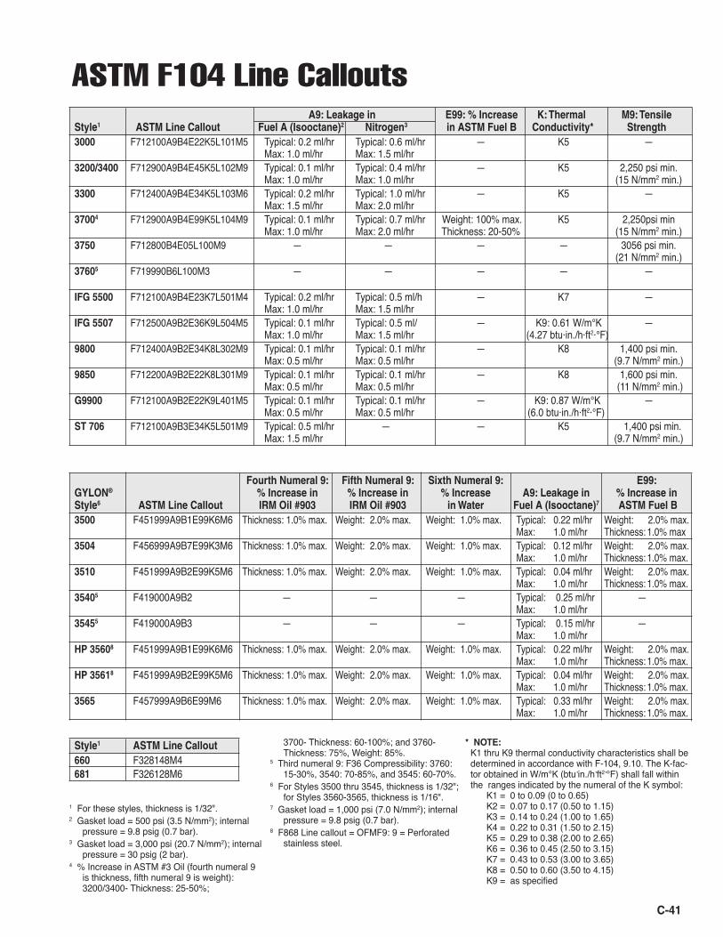
C-41
ASTM F104 Line Callouts A9: Leakage in E99: % Increase K: Thermal M9: Tensile Style1 ASTM Line Callout Fuel A (Isooctane)2 Nitrogen3 in ASTM Fuel B Conductivity* Strength3000 F712100A9B4E22K5L101M5 Typical: 0.2 ml/hr Typical: 0.6 ml/hr — K5 — Max: 1.0 ml/hr Max: 1.5 ml/hr3200/3400 F712900A9B4E45K5L102M9 Typical: 0.1 ml/hr Typical: 0.4 ml/hr — K5 2,250 psi min. Max: 1.0 ml/hr Max: 1.0 ml/hr (15 N/mm2 min.)3300 F712400A9B4E34K5L103M6 Typical: 0.2 ml/hr Typical: 1.0 ml/hr — K5 — Max: 1.5 ml/hr Max: 2.0 ml/hr37004 F712900A9B4E99K5L104M9 Typical: 0.1 ml/hr Typical: 0.7 ml/hr Weight: 100% max. K5 2,250psi min Max: 1.0 ml/hr Max: 2.0 ml/hr Thickness: 20-50% (15 N/mm2 min.)3750 F712800B4E05L100M9 — — — — 3056 psi min. (21 N/mm2 min.)37605 F719990B6L100M3 — — — — — IFG 5500 F712100A9B4E23K7L501M4 Typical: 0.2 ml/hr Typical: 0.5 ml/h — K7 — Max: 1.0 ml/hr Max: 1.5 ml/hrIFG 5507 F712500A9B2E36K9L504M5 Typical: 0.1 ml/hr Typical: 0.5 ml/ — K9: 0.61 W/m°K — Max: 1.0 ml/hr Max: 1.5 ml/hr (4.27 btu·in./h·ft2·°F) 9800 F712400A9B2E34K8L302M9 Typical: 0.1 ml/hr Typical: 0.1 ml/hr — K8 1,400 psi min. Max: 0.5 ml/hr Max: 0.5 ml/hr (9.7 N/mm2 min.)9850 F712200A9B2E22K8L301M9 Typical: 0.1 ml/hr Typical: 0.1 ml/hr — K8 1,600 psi min. Max: 0.5 ml/hr Max: 0.5 ml/hr (11 N/mm2 min.)G9900 F712100A9B2E22K9L401M5 Typical: 0.1 ml/hr Typical: 0.1 ml/hr — K9: 0.87 W/m°K — Max: 0.5 ml/hr Max: 0.5 ml/hr (6.0 btu·in./h·ft2·°F)ST 706 F712100A9B3E34K5L501M9 Typical: 0.5 ml/hr — — K5 1,400 psi min. Max: 1.5 ml/hr (9.7 N/mm2 min.)
1 For these styles, thickness is 1/32".2 Gasket load = 500 psi (3.5 N/mm2); internal
pressure = 9.8 psig (0.7 bar).3 Gasket load = 3,000 psi (20.7 N/mm2); internal
pressure = 30 psig (2 bar).4 % Increase in ASTM #3 Oil (fourth numeral 9
is thickness, fifth numeral 9 is weight): 3200/3400- Thickness: 25-50%;
Fourth Numeral 9: Fifth Numeral 9: Sixth Numeral 9: E99: GYLON® % Increase in % Increase in % Increase A9: Leakage in % Increase in Style6 ASTM Line Callout IRM Oil #903 IRM Oil #903 in Water Fuel A (Isooctane)7 ASTM Fuel B3500 F451999A9B1E99K6M6 Thickness: 1.0% max. Weight: 2.0% max. Weight: 1.0% max. Typical: 0.22 ml/hr Weight: 2.0% max. Max: 1.0 ml/hr Thickness: 1.0% max3504 F456999A9B7E99K3M6 Thickness: 1.0% max. Weight: 2.0% max. Weight: 1.0% max. Typical: 0.12 ml/hr Weight: 2.0% max. Max: 1.0 ml/hr Thickness: 1.0% max.3510 F451999A9B2E99K5M6 Thickness: 1.0% max. Weight: 2.0% max. Weight: 1.0% max. Typical: 0.04 ml/hr Weight: 2.0% max. Max: 1.0 ml/hr Thickness: 1.0% max.35405 F419000A9B2 — — — Typical: 0.25 ml/hr — Max: 1.0 ml/hr 35455 F419000A9B3 — — — Typical: 0.15 ml/hr — Max: 1.0 ml/hr HP 35608 F451999A9B1E99K6M6 Thickness: 1.0% max. Weight: 2.0% max. Weight: 1.0% max. Typical: 0.22 ml/hr Weight: 2.0% max. Max: 1.0 ml/hr Thickness: 1.0% max.HP 35618 F451999A9B2E99K5M6 Thickness: 1.0% max. Weight: 2.0% max. Weight: 1.0% max. Typical: 0.04 ml/hr Weight: 2.0% max. Max: 1.0 ml/hr Thickness: 1.0% max.3565 F457999A9B6E99M6 Thickness: 1.0% max. Weight: 2.0% max. Weight: 1.0% max. Typical: 0.33 ml/hr Weight: 2.0% max. Max: 1.0 ml/hr Thickness: 1.0% max.
Style1 ASTM Line Callout660 F328148M4681 F326128M6
3700- Thickness: 60-100%; and 3760- Thickness: 75%, Weight: 85%.
5 Third numeral 9: F36 Compressibility: 3760: 15-30%, 3540: 70-85%, and 3545: 60-70%.
6 For Styles 3500 thru 3545, thickness is 1/32"; for Styles 3560-3565, thickness is 1/16".
7 Gasket load = 1,000 psi (7.0 N/mm2); internal pressure = 9.8 psig (0.7 bar).
8 F868 Line callout = OFMF9: 9 = Perforated stainless steel.
* NOTE: K1 thru K9 thermal conductivity characteristics shall be
determined in accordance with F-104, 9.10. The K-fac-tor obtained in W/m°K (btu•in./h•ft2•°F) shall fall within the ranges indicated by the numeral of the K symbol:
K1 = 0 to 0.09 (0 to 0.65) K2 = 0.07 to 0.17 (0.50 to 1.15) K3 = 0.14 to 0.24 (1.00 to 1.65) K4 = 0.22 to 0.31 (1.50 to 2.15) K5 = 0.29 to 0.38 (2.00 to 2.65) K6 = 0.36 to 0.45 (2.50 to 3.15) K7 = 0.43 to 0.53 (3.00 to 3.65) K8 = 0.50 to 0.60 (3.50 to 4.15) K9 = as specified
C-42
Bolting and Flange Information
The gasketʼs function is to seal two different surfaces held together by one of several means, the most common being screw-threaded devices such as bolts. Sometimes the fastener itself must be sealed, as in the case of a steel drum bung.
The bolt is a spring. It is an elastic member that has been stretched to develop a load. The more spring pro-vided by the bolt, the better the retention of stress on the gasket to maintain a leakproof joint. It must not be over-elongated (over-strained), or the elastic limit of the steel will be exceeded. The bolt then deforms and, with contin-ued loading (stressing), may rupture.
To avoid such problems with bolt tightening, the use of a torque wrench is recommended. The torque tables on page C-44 show the recommended torque values for Garlock compressed sheet, GYLON® and GRAPH-LOCK® gasketing materials in 150 lb. and 300 lb. raised face flanges. The equipment designer may specify the recom-mended torque to prevent damage to the equipment from overtorquing. Garlockʼs recommended assembly stresses, page C-43, may help the equipment designer determine the maximum allowable torque per bolt. The load will be retained better by using a bolt with a longer grip, thereby ensuring a leakproof joint.
There are limits on the degree of flange surface imperfection that can be sealed successfully with a gasket. Large nicks, dents, or gouges must be avoided, since a gasket cannot properly seal against them. The surface fin-ish of a flange is described as follows:1. Roughness: Roughness is read in millionths of an inch (or meter) as the average of the peaks and valleys measured from a midline of the flange surface. This is ex-pressed either as rms (root mean square) or AA (arithmetic average). The difference between these two methods of reading is so small that they may be used interchangeably. Roughness is also expressed as AARH (arithmetic aver-age roughness height).2. Lay: Lay is the direction of the predominant surface-roughness pattern. Example: multidirectional, phonograph-ic spiral serrations, etc.3. Waviness: Waviness is measured in thousandths or fractions of an inch. Basically, it is the departure from overall flatness.
Typical roughness readings can be from 125 to 500 micro-inches for serrated flanges and 125-250 micro-inches for non-serrated flanges. Fine finishes, such as polished surfaces, should be avoided. Adequate "bite"
in the surface is required to develop enough friction to prevent the gasket from being blown out or from extruding or creeping excessively.
The lay of the finish should follow the midline of the gasket if possible. Take, for example, concentric circles on a round flange, or a phonographic spiral. Every effort should be made to avoid lines across the face, such as linear surface grinding, which at 180° points will cross the seal area at right angles to the gasket, allowing a direct leak path.
Waviness is seldom a problem under normal condi-tions. There are two areas that must be watched, however, since excessive waviness is very difficult to handle.
The first area is glass-lined equipment where the natural flow of the fused glass creates extreme waviness. Often the answer here is to use thick and highly compress-ible gasketing.
The second area of concern is warped flanges. If warpage is caused by heat or internal stresses, re-ma-chining is generally sufficient. However, warpage due to excessive bolt loads or insufficient flange thickness results in what is generally called bowing.
The solution is to redesign for greater flange rigidity. Sometimes backer plates can be added to strengthen the design without having to replace the parts. Another step would be to add more bolts. When this is done, usually smaller bolt diameters are possible, thus adding more bolt stretch and better joint performance.
Questions? Call Gasket Applications Engineering at 1-800-448-6688
®
GasketsGasketsGarlockGarlock
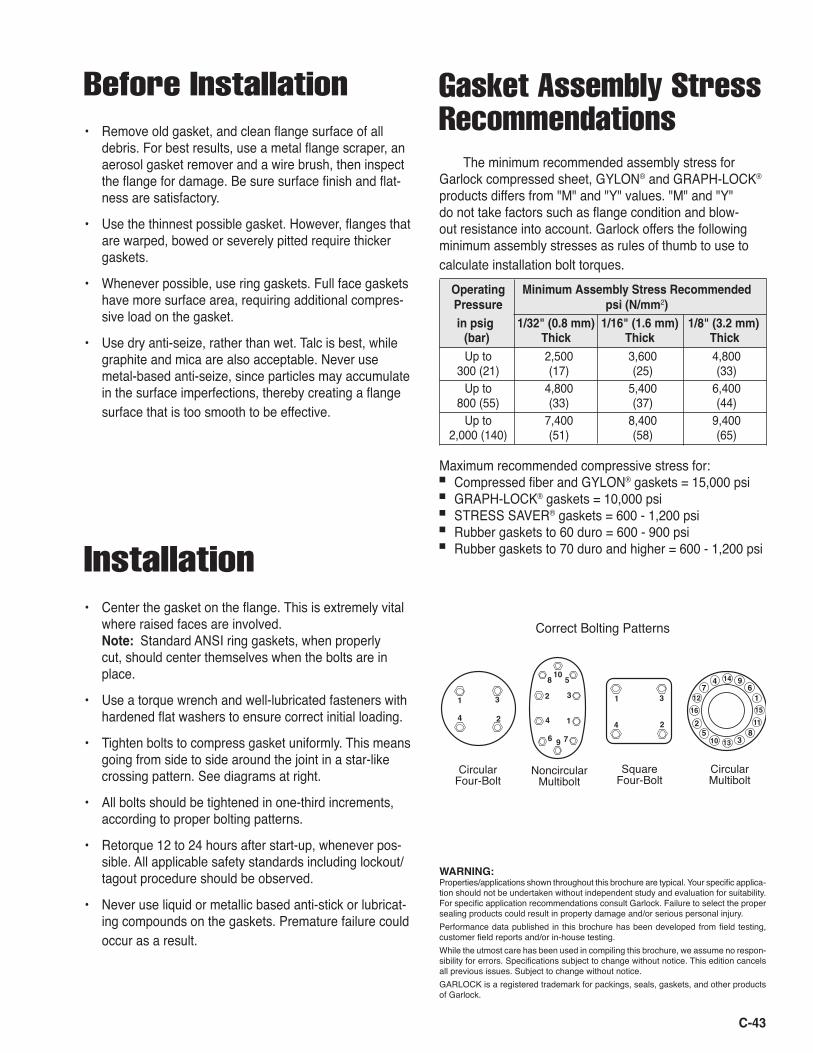
C-43
� �
�� �
� �
�
�
� �
�
�
��
�
��
��� ��
��
��
��
��
��
�
�
� �
�
�
�
�
�
CircularFour-Bolt
NoncircularMultibolt
SquareFour-Bolt
CircularMultibolt
� �
�� �
� �
�
�
� �
�
�
��
�
��
��� ��
��
��
��
��
��
�
�
� �
�
�
�
�
�
CircularFour-Bolt
NoncircularMultibolt
SquareFour-Bolt
CircularMultibolt
Before Installation• Remove old gasket, and clean flange surface of all
debris. For best results, use a metal flange scraper, an aerosol gasket remover and a wire brush, then inspect the flange for damage. Be sure surface finish and flat-ness are satisfactory.
• Use the thinnest possible gasket. However, flanges that are warped, bowed or severely pitted require thicker gaskets.
• Whenever possible, use ring gaskets. Full face gaskets have more surface area, requiring additional compres-sive load on the gasket.
• Use dry anti-seize, rather than wet. Talc is best, while graphite and mica are also acceptable. Never use metal-based anti-seize, since particles may accumulate in the surface imperfections, thereby creating a flange surface that is too smooth to be effective.
Installation• Center the gasket on the flange. This is extremely vital
where raised faces are involved. Note: Standard ANSI ring gaskets, when properly cut, should center themselves when the bolts are in place.
• Use a torque wrench and well-lubricated fasteners with hardened flat washers to ensure correct initial loading.
• Tighten bolts to compress gasket uniformly. This means going from side to side around the joint in a star-like crossing pattern. See diagrams at right.
• All bolts should be tightened in one-third increments, according to proper bolting patterns.
• Retorque 12 to 24 hours after start-up, whenever pos-sible. All applicable safety standards including lockout/tagout procedure should be observed.
• Never use liquid or metallic based anti-stick or lubricat-ing compounds on the gaskets. Premature failure could occur as a result.
The minimum recommended assembly stress for Garlock compressed sheet, GYLON® and GRAPH-LOCK® products differs from "M" and "Y" values. "M" and "Y" do not take factors such as flange condition and blow-out resistance into account. Garlock offers the following minimum assembly stresses as rules of thumb to use to calculate installation bolt torques. Operating Minimum Assembly Stress Recommended Pressure psi (N/mm2) in psig 1/32" (0.8 mm) 1/16" (1.6 mm) 1/8" (3.2 mm) (bar) Thick Thick Thick Up to 2,500 3,600 4,800 300 (21) (17) (25) (33) Up to 4,800 5,400 6,400 800 (55) (33) (37) (44) Up to 7,400 8,400 9,400 2,000 (140) (51) (58) (65)
Maximum recommended compressive stress for: ■ Compressed fiber and GYLON® gaskets = 15,000 psi■ GRAPH-LOCK® gaskets = 10,000 psi ■ STRESS SAVER® gaskets = 600 - 1,200 psi■ Rubber gaskets to 60 duro = 600 - 900 psi■ Rubber gaskets to 70 duro and higher = 600 - 1,200 psi
Correct Bolting Patterns
Gasket Assembly Stress Recommendations
WARNING:Properties/applications shown throughout this brochure are typical. Your specific applica-tion should not be undertaken without independent study and evaluation for suitability. For specific application recommendations consult Garlock. Failure to select the proper sealing products could result in property damage and/or serious personal injury. Performance data published in this brochure has been developed from field testing, customer field reports and/or in-house testing. While the utmost care has been used in compiling this brochure, we assume no respon-sibility for errors. Specifications subject to change without notice. This edition cancels all previous issues. Subject to change without notice. GARLOCK is a registered trademark for packings, seals, gaskets, and other products of Garlock.
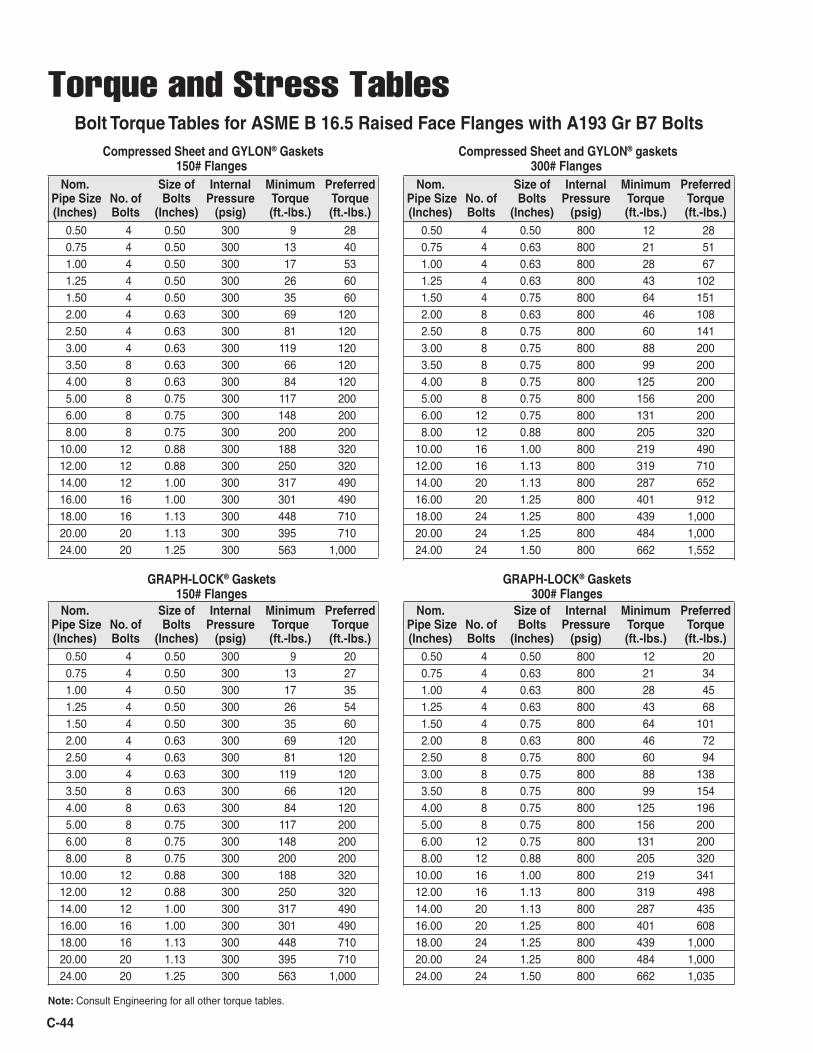
C-44
Nom. Size of Internal Minimum Preferred Pipe Size No. of Bolts Pressure Torque Torque (Inches) Bolts (Inches) (psig) (ft.-lbs.) (ft.-lbs.) 0.50 4 0.50 300 9 28 0.75 4 0.50 300 13 40 1.00 4 0.50 300 17 53 1.25 4 0.50 300 26 60 1.50 4 0.50 300 35 60 2.00 4 0.63 300 69 120 2.50 4 0.63 300 81 120 3.00 4 0.63 300 119 120 3.50 8 0.63 300 66 120 4.00 8 0.63 300 84 120 5.00 8 0.75 300 117 200 6.00 8 0.75 300 148 200 8.00 8 0.75 300 200 200 10.00 12 0.88 300 188 320 12.00 12 0.88 300 250 320 14.00 12 1.00 300 317 490 16.00 16 1.00 300 301 490 18.00 16 1.13 300 448 710 20.00 20 1.13 300 395 710 24.00 20 1.25 300 563 1,000
Nom. Size of Internal Minimum Preferred Pipe Size No. of Bolts Pressure Torque Torque (Inches) Bolts (Inches) (psig) (ft.-lbs.) (ft.-lbs.) 0.50 4 0.50 800 12 28 0.75 4 0.63 800 21 51 1.00 4 0.63 800 28 67 1.25 4 0.63 800 43 102 1.50 4 0.75 800 64 151 2.00 8 0.63 800 46 108 2.50 8 0.75 800 60 141 3.00 8 0.75 800 88 200 3.50 8 0.75 800 99 200 4.00 8 0.75 800 125 200 5.00 8 0.75 800 156 200 6.00 12 0.75 800 131 200 8.00 12 0.88 800 205 320 10.00 16 1.00 800 219 490 12.00 16 1.13 800 319 710 14.00 20 1.13 800 287 652 16.00 20 1.25 800 401 912 18.00 24 1.25 800 439 1,000 20.00 24 1.25 800 484 1,000 24.00 24 1.50 800 662 1,552
Torque and Stress TablesBolt Torque Tables for ASME B 16.5 Raised Face Flanges with A193 Gr B7 Bolts
Nom. Size of Internal Minimum Preferred Pipe Size No. of Bolts Pressure Torque Torque (Inches) Bolts (Inches) (psig) (ft.-lbs.) (ft.-lbs.) 0.50 4 0.50 300 9 20 0.75 4 0.50 300 13 27 1.00 4 0.50 300 17 35 1.25 4 0.50 300 26 54 1.50 4 0.50 300 35 60 2.00 4 0.63 300 69 120 2.50 4 0.63 300 81 120 3.00 4 0.63 300 119 120 3.50 8 0.63 300 66 120 4.00 8 0.63 300 84 120 5.00 8 0.75 300 117 200 6.00 8 0.75 300 148 200 8.00 8 0.75 300 200 200 10.00 12 0.88 300 188 320 12.00 12 0.88 300 250 320 14.00 12 1.00 300 317 490 16.00 16 1.00 300 301 490 18.00 16 1.13 300 448 710 20.00 20 1.13 300 395 710 24.00 20 1.25 300 563 1,000
Nom. Size of Internal Minimum Preferred Pipe Size No. of Bolts Pressure Torque Torque (Inches) Bolts (Inches) (psig) (ft.-lbs.) (ft.-lbs.) 0.50 4 0.50 800 12 20 0.75 4 0.63 800 21 34 1.00 4 0.63 800 28 45 1.25 4 0.63 800 43 68 1.50 4 0.75 800 64 101 2.00 8 0.63 800 46 72 2.50 8 0.75 800 60 94 3.00 8 0.75 800 88 138 3.50 8 0.75 800 99 154 4.00 8 0.75 800 125 196 5.00 8 0.75 800 156 200 6.00 12 0.75 800 131 200 8.00 12 0.88 800 205 320 10.00 16 1.00 800 219 341 12.00 16 1.13 800 319 498 14.00 20 1.13 800 287 435 16.00 20 1.25 800 401 608 18.00 24 1.25 800 439 1,000 20.00 24 1.25 800 484 1,000 24.00 24 1.50 800 662 1,035
Note: Consult Engineering for all other torque tables.
Compressed Sheet and GYLON® Gaskets150# Flanges
Compressed Sheet and GYLON® gaskets300# Flanges
GRAPH-LOCK® Gaskets300# Flanges
GRAPH-LOCK® Gaskets150# Flanges
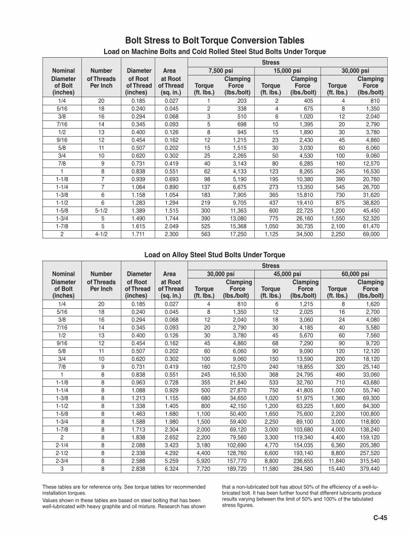
C-45
Load on Machine Bolts and Cold Rolled Steel Stud Bolts Under Torque Stress Nominal Number Diameter Area 7,500 psi 15,000 psi 30,000 psi Diameter of Threads of Root at Root Clamping Clamping Clamping of Bolt Per Inch of Thread of Thread Torque Force Torque Force Torque Force (inches) (inches) (sq. in.) (ft. lbs.) (lbs./bolt) (ft. lbs.) (lbs./bolt) (ft. lbs.) (lbs./bolt) 1/4 20 0.185 0.027 1 203 2 405 4 810 5/16 18 0.240 0.045 2 338 4 675 8 1,350 3/8 16 0.294 0.068 3 510 6 1,020 12 2,040 7/16 14 0.345 0.093 5 698 10 1,395 20 2,790 1/2 13 0.400 0.126 8 945 15 1,890 30 3,780 9/16 12 0.454 0.162 12 1,215 23 2,430 45 4,860 5/8 11 0.507 0.202 15 1,515 30 3,030 60 6,060 3/4 10 0.620 0.302 25 2,265 50 4,530 100 9,060 7/8 9 0.731 0.419 40 3,143 80 6,285 160 12,570 1 8 0.838 0.551 62 4,133 123 8,265 245 16,530 1-1/8 7 0.939 0.693 98 5,190 195 10,380 390 20,760 1-1/4 7 1.064 0.890 137 6,675 273 13,350 545 26,700 1-3/8 6 1.158 1.054 183 7,905 365 15,810 730 31,620 1-1/2 6 1.283 1.294 219 9,705 437 19,410 875 38,820 1-5/8 5-1/2 1.389 1.515 300 11,363 600 22,725 1,200 45,450 1-3/4 5 1.490 1.744 390 13,080 775 26,160 1,550 52,320 1-7/8 5 1.615 2.049 525 15,368 1,050 30,735 2,100 61,470 2 4-1/2 1.711 2.300 563 17,250 1,125 34,500 2,250 69,000
Load on Alloy Steel Stud Bolts Under Torque Stress Nominal Number Diameter Area 30,000 psi 45,000 psi 60,000 psi Diameter of Threads of Root at Root Clamping Clamping Clamping of Bolt Per Inch of Thread of Thread Torque Force Torque Force Torque Force (inches) (inches) (sq. in.) (ft. lbs.) (lbs./bolt) (ft. lbs.) (lbs./bolt) (ft. lbs.) (lbs./bolt) 1/4 20 0.185 0.027 4 810 6 1,215 8 1,620 5/16 18 0.240 0.045 8 1,350 12 2,025 16 2,700 3/8 16 0.294 0.068 12 2,040 18 3,060 24 4,080 7/16 14 0.345 0.093 20 2,790 30 4,185 40 5,580 1/2 13 0.400 0.126 30 3,780 45 5,670 60 7,560 9/16 12 0.454 0.162 45 4,860 68 7,290 90 9,720 5/8 11 0.507 0.202 60 6,060 90 9,090 120 12,120 3/4 10 0.620 0.302 100 9,060 150 13,590 200 18,120 7/8 9 0.731 0.419 160 12,570 240 18,855 320 25,140 1 8 0.838 0.551 245 16,530 368 24,795 490 33,060 1-1/8 8 0.963 0.728 355 21,840 533 32,760 710 43,680 1-1/4 8 1.088 0.929 500 27,870 750 41,805 1,000 55,740 1-3/8 8 1.213 1.155 680 34,650 1,020 51,975 1,360 69,300 1-1/2 8 1.338 1.405 800 42,150 1,200 63,225 1,600 84,300 1-5/8 8 1.463 1.680 1,100 50,400 1,650 75,600 2,200 100,800 1-3/4 8 1.588 1.980 1,500 59,400 2,250 89,100 3,000 118,800 1-7/8 8 1.713 2.304 2,000 69,120 3,000 103,680 4,000 138,240 2 8 1.838 2.652 2,200 79,560 3,300 119,340 4,400 159,120 2-1/4 8 2.088 3.423 3,180 102,690 4,770 154,035 6,360 205,380 2-1/2 8 2.338 4.292 4,400 128,760 6,600 193,140 8,800 257,520 2-3/4 8 2.588 5.259 5,920 157,770 8,800 236,655 11,840 315,540 3 8 2.838 6.324 7,720 189,720 11,580 284,580 15,440 379,440
Values shown in these tables are based on steel bolting that has been well-lubricated with heavy graphite and oil mixture. Research has shown
that a non-lubricated bolt has about 50% of the efficiency of a well-lu-bricated bolt. It has been further found that different lubricants produce results varying between the limit of 50% and 100% of the tabulated stress figures.
These tables are for reference only. See torque tables for recommended installation torques.
Bolt Stress to Bolt Torque Conversion Tables
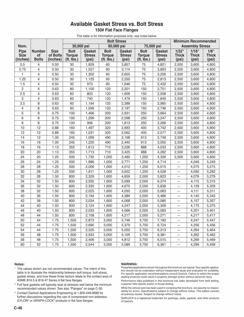
C-46
Bolt Stress Minimum Recommended Nom. 30,000 psi 60,000 psi 75,000 psi Assembly Stress Pipe Number Size Bolt Gasket Bolt Gasket Bolt Gasket 1/32" 1/16" 1/8" Size of of Bolts Torque Stress Torque Stress Torque Stress Thick Thick Thick (inches) Bolts (inches) (ft. lbs.) (psi) (ft. lbs.) (psi) (ft. lbs.) (psi) (psi) (psi) (psi) 0.5 4 0.50 30 1,929 60 3,857 75 4,821 2,500 3,600 4,800 0.75 4 0.50 30 1,557 60 3,114 75 3,893 2,500 3,600 4,800 1 4 0.50 30 1,302 60 2,605 75 3,256 2,500 3,600 4,800 1.25 4 0.50 30 1,125 60 2,250 75 2,813 2,500 3,600 4,800 1.5 4 0.50 30 973 60 1,946 75 2,432 2,500 3,600 4,800 2 4 0.63 60 1,100 120 2,201 150 2,751 2,500 3,600 4,800 2.5 4 0.63 60 803 120 1,606 150 2,008 2,500 3,600 4,800 3 4 0.63 60 740 120 1,479 150 1,849 2,500 3,600 4,800 3.5 8 0.63 60 1,194 120 2,388 150 2,985 2,500 3,600 4,800 4 8 0.63 60 1,099 120 2,197 150 2,746 2,500 3,600 4,800 5 8 0.75 100 1,466 200 2,931 250 3,664 2,500 3,600 4,800 6 8 0.75 100 1,299 200 2,598 250 3,247 2,500 3,600 4,800 8 8 0.75 100 906 200 1,813 250 2,266 2,500 3,600 4,800 10 12 0.88 160 1,497 320 2,993 400 3,742 2,500 3,600 4,800 12 12 0.88 160 1,031 320 2,062 400 2,577 2,500 3,600 4,800 14 12 1.00 245 1,099 490 2,198 613 2,748 2,500 3,600 4,800 16 16 1.00 245 1,220 490 2,440 613 3,050 2,500 3,600 4,800 18 16 1.13 355 1,613 710 3,226 888 4,033 2,500 3,600 4,800 20 20 1.13 355 1,713 710 3,425 888 4,282 2,500 3,600 4,800 24 20 1.25 500 1,730 1,000 3,460 1,250 4,326 2,500 3,600 4,800 26 24 1.25 500 1,886 1,000 3,771 1,250 4,714 — 4,049 5,249 28 28 1.25 500 2,006 1,000 4,012 1,250 5,015 — 4,075 5,275 30 28 1.25 500 1,811 1,000 3,622 1,250 4,528 — 4,092 5,292 32 28 1.50 800 2,329 1,600 4,659 2,000 5,823 — 4,076 5,276 34 32 1.50 800 2,550 1,600 5,099 2,000 6,374 — 4,115 5,315 36 32 1.50 800 2,335 1,600 4,670 2,000 5,838 — 4,129 5,329 38 32 1.50 800 2,025 1,600 4,050 2,000 5,063 — 4,111 5,311 40 36 1.50 800 2,194 1,600 4,389 2,000 5,486 — 4,145 5,345 42 36 1.50 800 2,034 1,600 4,068 2,000 5,085 — 4,157 5,357 44 40 1.50 800 2,124 1,600 4,247 2,000 5,309 — 4,175 5,375 46 40 1.50 800 2,033 1,600 4,066 2,000 5,083 — 4,201 5,401 48 44 1.50 800 2,108 1,600 4,217 2,000 5,271 — 4,217 5,417 50 44 1.75 1,500 2,873 3,000 5,746 3,750 7,182 — 4,247 5,447 52 44 1.75 1,500 2,690 3,000 5,379 3,750 6,724 — 4,256 5,456 54 44 1.75 1,500 2,525 3,000 5,050 3,750 6,313 — 4,264 5,464 56 48 1.75 1,500 2,553 3,000 5,105 3,750 6,381 — 4,262 5,462 58 48 1.75 1,500 2,406 3,000 4,812 3,750 6,015 — 4,269 5,469 60 52 1.75 1,500 2,544 3,000 5,089 3,750 6,361 — 4,299 5,499
Available Gasket Stress vs. Bolt Stress 150# Flat Face Flanges
This table is for information purposes only; see notes below.
Notes:1 The values shown are not recommended values. The intent of this
table is to illustrate the relationship between bolt torque, bolt stress, gasket stress, and how these three factors relate to the contact area of ASME B16.5 & B16.47 Series A flat face flanges.
2 Full face gaskets will typically seal at stresses well below the minimum recommended values shown. See also “Flanges” on page C-50.
3 Contact Garlock Applications Engineering at 1-800-448-6688 for further discussions regarding the use of compressed non-asbestos, GYLON® or GRAPH-LOCK® products in flat face flanges.
WARNING:Properties/applications shown throughout this brochure are typical. Your specific applica-tion should not be undertaken without independent study and evaluation for suitability. For specific application recommendations consult Garlock. Failure to select the proper sealing products could result in property damage and/or serious personal injury. Performance data published in this brochure has been developed from field testing, customer field reports and/or in-house testing. While the utmost care has been used in compiling this brochure, we assume no respon-sibility for errors. Specifications subject to change without notice. This edition cancels all previous issues. Subject to change without notice. GARLOCK is a registered trademark for packings, seals, gaskets, and other products of Garlock.
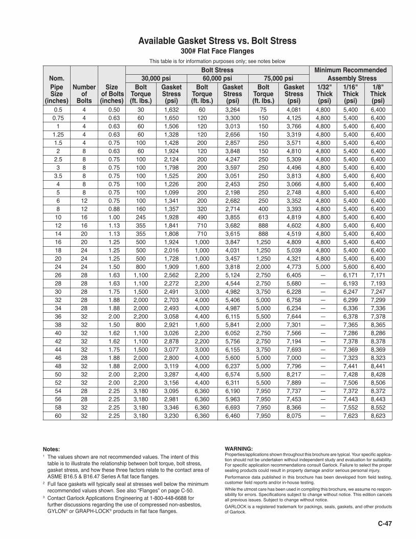
C-47
Available Gasket Stress vs. Bolt Stress 300# Flat Face Flanges
This table is for information purposes only; see notes below Bolt Stress Minimum Recommended Nom. 30,000 psi 60,000 psi 75,000 psi Assembly Stress Pipe Number Size Bolt Gasket Bolt Gasket Bolt Gasket 1/32" 1/16" 1/8" Size of of Bolts Torque Stress Torque Stress Torque Stress Thick Thick Thick (inches) Bolts (inches) (ft. lbs.) (psi) (ft. lbs.) (psi) (ft. lbs.) (psi) (psi) (psi) (psi) 0.5 4 0.50 30 1,632 60 3,264 75 4,081 4,800 5,400 6,400 0.75 4 0.63 60 1,650 120 3,300 150 4,125 4,800 5,400 6,400 1 4 0.63 60 1,506 120 3,013 150 3,766 4,800 5,400 6,400 1.25 4 0.63 60 1,328 120 2,656 150 3,319 4,800 5,400 6,400 1.5 4 0.75 100 1,428 200 2,857 250 3,571 4,800 5,400 6,400 2 8 0.63 60 1,924 120 3,848 150 4,810 4,800 5,400 6,400 2.5 8 0.75 100 2,124 200 4,247 250 5,309 4,800 5,400 6,400 3 8 0.75 100 1,798 200 3,597 250 4,496 4,800 5,400 6,400 3.5 8 0.75 100 1,525 200 3,051 250 3,813 4,800 5,400 6,400 4 8 0.75 100 1,226 200 2,453 250 3,066 4,800 5,400 6,400 5 8 0.75 100 1,099 200 2,198 250 2,748 4,800 5,400 6,400 6 12 0.75 100 1,341 200 2,682 250 3,352 4,800 5,400 6,400 8 12 0.88 160 1,357 320 2,714 400 3,393 4,800 5,400 6,400 10 16 1.00 245 1,928 490 3,855 613 4,819 4,800 5,400 6,400 12 16 1.13 355 1,841 710 3,682 888 4,602 4,800 5,400 6,400 14 20 1.13 355 1,808 710 3,615 888 4,519 4,800 5,400 6,400 16 20 1.25 500 1,924 1,000 3,847 1,250 4,809 4,800 5,400 6,400 18 24 1.25 500 2,016 1,000 4,031 1,250 5,039 4,800 5,400 6,400 20 24 1.25 500 1,728 1,000 3,457 1,250 4,321 4,800 5,400 6,400 24 24 1.50 800 1,909 1,600 3,818 2,000 4,773 5,000 5,600 6,400 26 28 1.63 1,100 2,562 2,200 5,124 2,750 6,405 — 6,171 7,171 28 28 1.63 1,100 2,272 2,200 4,544 2,750 5,680 — 6,193 7,193 30 28 1.75 1,500 2,491 3,000 4,982 3,750 6,228 — 6,247 7,247 32 28 1.88 2,000 2,703 4,000 5,406 5,000 6,758 — 6,299 7,299 34 28 1.88 2,000 2,493 4,000 4,987 5,000 6,234 — 6,336 7,336 36 32 2.00 2,200 3,058 4,400 6,115 5,500 7,644 — 6,378 7,378 38 32 1.50 800 2,921 1,600 5,841 2,000 7,301 — 7,365 8,365 40 32 1.62 1,100 3,026 2,200 6,052 2,750 7,566 — 7,286 8,286 42 32 1.62 1,100 2,878 2,200 5,756 2,750 7,194 — 7,378 8,378 44 32 1.75 1,500 3,077 3,000 6,155 3,750 7,693 — 7,369 8,369 46 28 1.88 2,000 2,800 4,000 5,600 5,000 7,000 — 7,323 8,323 48 32 1.88 2,000 3,119 4,000 6,237 5,000 7,796 — 7,441 8,441 50 32 2.00 2,200 3,287 4,400 6,574 5,500 8,217 — 7,428 8,428 52 32 2.00 2,200 3,156 4,400 6,311 5,500 7,889 — 7,506 8,506 54 28 2.25 3,180 3,095 6,360 6,190 7,950 7,737 — 7,372 8,372 56 28 2.25 3,180 2,981 6,360 5,963 7,950 7,453 — 7,443 8,443 58 32 2.25 3,180 3,346 6,360 6,693 7,950 8,366 — 7,552 8,552 60 32 2.25 3,180 3,230 6,360 6,460 7,950 8,075 — 7,623 8,623
Notes:1 The values shown are not recommended values. The intent of this
table is to illustrate the relationship between bolt torque, bolt stress, gasket stress, and how these three factors relate to the contact area of ASME B16.5 & B16.47 Series A flat face flanges.
2 Full face gaskets will typically seal at stresses well below the minimum recommended values shown. See also “Flanges” on page C-50.
3 Contact Garlock Applications Engineering at 1-800-448-6688 for further discussions regarding the use of compressed non-asbestos, GYLON® or GRAPH-LOCK® products in flat face flanges.
WARNING:Properties/applications shown throughout this brochure are typical. Your specific applica-tion should not be undertaken without independent study and evaluation for suitability. For specific application recommendations consult Garlock. Failure to select the proper sealing products could result in property damage and/or serious personal injury. Performance data published in this brochure has been developed from field testing, customer field reports and/or in-house testing. While the utmost care has been used in compiling this brochure, we assume no respon-sibility for errors. Specifications subject to change without notice. This edition cancels all previous issues. Subject to change without notice. GARLOCK is a registered trademark for packings, seals, gaskets, and other products of Garlock.
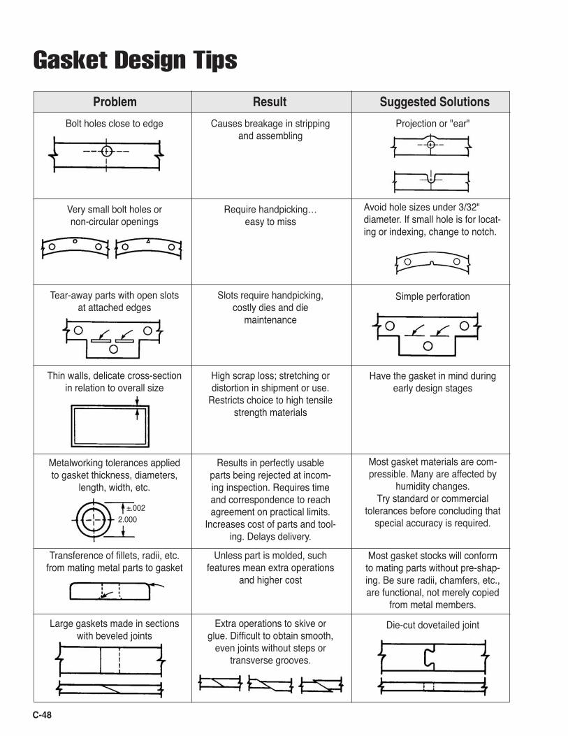
C-48
Gasket Design Tips
Problem Result Suggested Solutions
Projection or "ear"
Notch instead of hole
Avoid hole sizes under 3/32" diameter. If small hole is for locat-ing or indexing, change to notch.
Simple perforation
Have the gasket in mind during early design stages
Most gasket materials are com-pressible. Many are affected by
humidity changes. Try standard or commercial
tolerances before concluding that special accuracy is required.
Most gasket stocks will conform to mating parts without pre-shap-ing. Be sure radii, chamfers, etc., are functional, not merely copied
from metal members.
Die-cut dovetailed joint
Bolt holes close to edge
Very small bolt holes or non-circular openings
Tear-away parts with open slots at attached edges
Thin walls, delicate cross-section in relation to overall size
Metalworking tolerances applied to gasket thickness, diameters,
length, width, etc.
Transference of fillets, radii, etc. from mating metal parts to gasket
Large gaskets made in sections with beveled joints
Causes breakage in stripping and assembling
Require handpicking… easy to miss
Slots require handpicking, costly dies and die
maintenance
High scrap loss; stretching or distortion in shipment or use.
Restricts choice to high tensile strength materials
Results in perfectly usable parts being rejected at incom-ing inspection. Requires time and correspondence to reach agreement on practical limits.
Increases cost of parts and tool-ing. Delays delivery.
Unless part is molded, such features mean extra operations
and higher cost
Extra operations to skive or glue. Difficult to obtain smooth,
even joints without steps or transverse grooves.
2.000±.002
C-49
Gasketing TermsAmerican Bureau of Shipping
Garlock styles on the American Bureau of Shipping Type Approval program:
• ST-706 • BLUE-GARD® 3000, 3200 • GRAPH-LOCK® 3125SS, 3125TC • GYLON® 3500, 3504, 3510 • IFG® 5500* • 8459** • 9200 • G-9900* • 2400
Anti-Stick While we prefer that gaskets be installed with only the
factory-applied anti-stick, experience shows that additional anti-stick is helpful in some situations, such as areas where flanges cannot be separated easily. Coatings should be as light as possible. Dry powders are strongly recommended over pastes and grease-type compounds, which can drasti-cally reduce the crush strength and blowout resistance of the gasket. Additionally, grease or paste type materials may deteriorate or dissolve in service, leaving a possible leak path across the gasket.
Aviation Gasoline Gasoline with a high octane number is used for prop
driven airplane engines, as opposed to jet fuel for jet engines. Aviation gasoline contains a high percentage of aromatics. GYLON® is preferred; compressed sheet styles with nitrile binders can be successful in some applications (see Jet Fuel). Consult Engineering if you are unsure.
Bubble Tests Some end users perform bubble tests of their sys-
tem to check gasket tightness. This information is helpful before specifying a gasket. Bubble tests are an extremely tough test for a gasketed joint, and may not be an ap-propriate means to verify correct installation. Lightweight flanges with low available compressive load may never achieve "bubble tight" results.
Chlorine Service We recommend our GYLON® styles for chlorine. The
style selection is made based on flange information. Style 3510 is listed in the Chlorine Instituteʼs Pamphlet 95. Garlock Metallic Gasket Division products are also listed, including the GRAPHONIC® gasket.
Compression The amount of compression expected on a particular
gasket type depends on its compressibility data and the load applied. Sealing problems are often a result of lack of compression. Graphs of compression vs. Ioad on popular gasketing styles are available upon request. Close toler-ance sheet should be considered for applications requiring tight internal clearances such as split case pumps (see Modulus of Elasticity).
Compressive Stress Undercompression: Underloaded gaskets will have
higher leak rates and lower blowout resistance than prop-erly loaded gaskets. This has a profound effect on perfor-mance and is the most frequent cause of joint problems.
Overcompression: Overcompression can lead to crushing, which accelerates the degradation of the gasket and can even cause immediate failure.
Uneven Compression: Gaskets resist blowout based on the friction of the gasket against the flange. The higher the compressive load, both initially and during service, the higher the blowout resistance. When areas of high and low compression exist in a flange joint, the areas of low compression are prime candidates for blowout.
Crush Strength Garlock recommends a maximum compressive stress
of 15,000 psi on compressed fiber and GYLON® gasket-ing, and 10,000 psi on GRAPH-LOCK® gasketing. The actual crush strength of these materials is typically higher than that of homogeneous rubber.
Cryogenic Service We recommend our GYLON® styles down to
-450°F (-268°C), and our compressed sheet gasketing is typically recommended to -100°F (-75°C).
Dielectric Breakdown Voltage Many applications require a gasket which is not
a good conductor of electricity. Garlock has dielectric breakdown voltage test data available on our most popular gasketing styles. Generally speaking, GYLON® styles and compressed sheet that does not use carbon or graphite fibers have high dielectric breakdown values. Under humid or wet conditions, Styles 3504 and 3565 are particularly resistant to dielectric breakdown.
* Accepted for use where “fire safe” requirements are specified by ABS rules, and US Coast Guard regulations.
** Non-stocked item.
Emissions There is certainly a great deal of interest in limiting
emissions of the numerous chemicals and other sub-stances regulated under the Clean Air Act. Garlock has performed testing in this area and our report, available on request, covers the effects of gasket type, compressive load, internal pressure and flange finish on relative emis-sions levels. The use of heavier flanges where possible and the selection of premium gasket materials with good sealability numbers are the easiest ways to reduce emis-sions.
FDA Style 3500 (Fawn) and Style 3510 (Off-White) comply
with FDA regulation 21CFR177.1550. They meet ingredi-ent and extract requirements. The fillers are also accept-able under 21CFR177.2600 and coloring agents (where used) under 21CFR178.3297. The branding ink complies with 21CFR175.300. Style 3500 (Fawn) has USDA ap-proval for direct contact in meat and poultry applications.
Style 3504 (Blue), Style 3565 (ENVELON®), Style 3591 (Gold), and Style 3594 (Green) comply with FDA regulation 21CFR177.1550. They meet the ingredient and extract requirements. The filler is listed in the Food Chemicals Codex (FCC 3rd Edition) and is considered GRAS (generally recognized as safe – 21CFR170.30). The branding ink complies with 21CFR175.300.
Style 3522 (Clear) complies with FDA regulation 21CFR177.1550.
The ingredients for Style 3540 (Microcellular) and Style 3545 (Microcellular with Rigid Core) comply with FDA regulations 21CFR177.1550, 21CFR182.1, 21CFR182.1217, and 21CFR175.300. The branding ink complies with 21CFR175.300.
The PTFE resins used in Style 3535 PTFE joint sealant comply with FDA regulation 21CFR177.1550. The PSA tape used to hold the joint sealant material in place meets 21CFR175.105.
Fire Tests Garlock has developed a Fire Test Standard modeled
after industry fire tests API 589 and 607. Styles G-9900, 9800, 9850, ST-706, IFG® 5500 and GRAPH-LOCK® styles have all passed this fire test. Test procedures and results are available upon request.
Flanges Flanges come in all shapes and sizes, and the type of
flange used in a service has a large impact on the type of gasketing material recommended. Standard ANSI raised face flanges are best suited for use with compressed fiber
and GYLON® gaskets. Elastomer (rubber) gaskets may be crushed in these flanges.
Flat faced non-metallic flanges seal best with elas-tomeric (rubber) gaskets, such as the various STRESS SAVER® gasket styles. GYLON® Style 3545 may also be suitable for some applications. Compressed fiber and standard GYLON® are frequently used in flat-faced carbon steel flanges, but the compressive stress available in these flanges is well below our minimums. The result is that the gaskets are compressed very little; if there is a significant flange irregularity present, the gasket may not seal. Since leakage rates of gaskets depend on the avail-able compressive stress, the joint may not be as tight as the customer would like.
Glass-lined flanges are found in many chemical applications. Due to the inherent "waviness" created when these flanges are fired to apply the glass, the softer GYLON® styles such as Styles 3545, 3565, and 3504 are preferred. The gap between the flanges, when placed together empty, must be measured before the gasket is ordered. Gasket thickness should be four to five times the maximum gap observed.
Stainless steel (SS) flanges are common in many plants for chemical service, and often utilize low strength SS bolts. Due to the chemicals present and the low com-pressive stress generated by the bolts, Styles 3545, 3565, and 3504 are often recommended. We do prefer, however, the use of high strength, strain-hardened stainless steel bolts.
Flange Finish We recommend the flange finish conform, whenever
possible, to 30-55 serrations per inch, in a concentric or spiral pattern, cut with a 1/16" radius, round-nosed tool. This finish is usually difficult or impossible to create in non-circular flanges. We recommend that machined sur-faces which can not be serrated have a surface finish with a multi-directional lay and roughness of 125-250 micro-inch RMS.
Fuel Additives The chemical MTBE (methyl t-butyl ether) has be-
come a very common fuel additive and gasketing com-patibility inquiries on this material are frequent. Garlock in-house testing has shown GYLON® gasketing to be unaffected by MTBE. We have also found compressed sheet Styles 9850 and 3000 to be suitable for MTBE ser-vice. These materials are recommended for MTBE alone or mixed with gasoline.
C-50
C-51
Full Face Gaskets See Flanges.
Gasket Constants The ASME and ASTM committees are working on a
new system and new set of numbers to be used in the ASME code calculations for flange design. These new constants address leak rates at installation and during loss of compressive load and therefore are meant to help end users design for a certain leak level. The use of a defined leak rate will generally generate much higher bolt load requirements for the flanges, which should improve perfor-mance of designed joints. For gasket constant values, see page C-40. Also see M & Y Values and Emissions.
Gasket Grooves Gaskets installed in grooves or tongue and groove
flanges require one extra consideration: the compressed height of the gasket must fill the groove. This is typically important where a highly compressible gasket such as GYLON® Styles 3545 and 3540 or one of the GRAPH-LOCK® styles is used to replace a compressed sheet gasket. The fully compressed thickness, not the original thickness, must be greater than the groove depth or the space between the tongue and groove when flanges con-tact each other. Ideally, the tongue should be at least as tall as the groove depth.
Gasohol Gasohol is a blend of gasoline with an alcohol— usu-
ally 15% ethyl alcohol. GYLON® styles are preferred; nitrile-bound compressed sheet styles should be accept-able; most rubber gaskets are not recommended.
Installation Garlock strongly recommends the use of calibrated
torque wrenches to tighten bolts to the correct load. We have an installation procedure and discussion available upon request. A video covering the same material is also available.
Insulation Kits Customers will occasionally ask for a flange insulation
or isolation kit or gasket to electrically insulate one flange from the mating flange. Kits are available from a variety of distributors and include an insulating gasket along with a sleeve for the bolts and insulating washer to be installed under the steel washers and nuts.
Garlock does not currently sell kits, but we do offer many gasket styles with good electrical insulating proper-ties (see Dielectric Breakdown Voltage).
Jet Fuels Jet fuels are typically refined petroleum products
similar to kerosene. We recommend our GYLON®, nitrile bound compressed sheet and GRAPH-LOCK® products. (See Aviation Gasoline)
Leachable Levels (chemical) Some pipe specifications call out maximum levels of
"leachables" for gaskets. These limits are usually con-cerned with leachable chlorides, fluorides, halogens and sulfur. These ions, or charged particles, are of concern due to their tendency to promote corrosion of piping systems. Garlock keeps test results for numerous gasket styles on file and we will test and certify leachable chlo-rides, etc., where required. There is a charge for these tests. Due to the nature of this type of analysis, we publish "typical" leachables only on certain styles such as our nuclear grade Style 9920.
"M" and "Y" Values for Flange DesignSee page C-40.Note: Our testing shows an increase in "M" and "Y"
values as gasket thickness increases. This is the opposite of the trend found in the ASME Code. Fugitive emission and gasket blowout studies have validated this trend.
Modulus of Elasticity Some flange programs ask for the modulus of elastic-
ity for the gasket material. This could be erroneous, since only rubber gaskets are elastic. Other types of gasketing do not have a true modulus. Garlock Appli-cations Engi-neering does have compression vs. Ioad curves which can be inverted to calculate a rough esti-mate for use in these calculations (see Compression).
Monomers Monomers are materials, such as styrene and vinyl
chloride, which can combine with themselves and become polymers, such as polystyrene and polyvinyl chloride. GY-LON® Styles 3510 and 3530 are recommended for mono-mers, since elastomer-bound gaskets are rarely compat-ible with monomers. Some monomers, under certain conditions, will penetrate a gasket and polymerize inside the gasket, causing the gasket to swell and, occasionally, rupture. This effect is known as "popcorning". This effect can be reduced or eliminated with additional compressive load which lowers the void space inherent in a gasket.
C-52
Oxidizers Certain chemicals are known as strong oxidizers and,
as such, will readily combine with organic compounds. We recommend our GYLON® material for use in oxidizers.
Oxygen Service We recommend GYLON® Styles 3502, 3505, 3503
and metal-inserted Styles 3562 and 3563. These gaskets are specially manufactured and packaged to eliminate contamination by organic material.
pHThe pH scale is a measure of the acidity or alkalinity
of a solution. A pH of 7 is a neutral reading; it is neither acidic or alkaline. Readings of 1-2 are strongly acidic, while 13-14 indicates a strong alkaline or caustic media.
Note: A pH reading alone without the names of the chemicals involved is not enough to select a gasket. Also, since the pH scale is quite limited in range, a reading of "1" or "14" does not fully describe the concentration. We need the concentration expressed as a percentage. For example, sodium hydroxide at a con-centration of around 4% will "peg" the pH scale at 14, the same reading pro-duced by a 40% concentration.
Pressure Spikes Very high pressure spikes can occur in any line pump-
ing a liquid if a valve is closed rapidly, leaving the fluid flow nowhere to go. The inertia of the fluid may create extreme pressure spikes. These spikes occur too rapidly to be detected by a pressure gage but can cause a gasket to blow out.
Radiation Resistance We have conducted gamma radiation tests on our
compressed sheet Styles 3000, 3200, 3400, 3700, 5500, 5507, 9800, 9850, 9920 and ST-706. These tests indicate our compressed non-asbestos styles will handle a total exposure of approximately 5 x 10⁷ rads of gamma radia-tion. GYLON® Styles 3510 and 3545 have been tested. Test results are available.
Refrigerants A number of new refrigerants have been introduced
in an effort to protect the environment. CFC-type refriger-ants, believed to be responsible for depleting the ozone layer, are being phased out and replaced by HCFCs and HFCs. Our most frequent compatibility inquiries concen-
trate on R-134a, R-123 and R-141b. Information provided by refrigerant manufacturers indicates Style 3300 will be preferred for R-134a and R-123. Styles 5500, 3000 and 3300 are recommended for R-141b. Refer to the Chemical Resistance chart for a complete listing of refrigerants. The compatibility of the lubricants used with these refrigerants should be considered.
Reuse of Gaskets We are frequently asked about reusing a gasket. We
do not recommend this practice. A gasketʼs function is to conform to flange high and low spots when compressed, and its ability to reseal decreases after it is compressed. Gaskets which contain rubber and which have experienced elevated temperatures will be even less likely to reseal.
Shelf Life Garlock has spec sheets detailing proper storage con-
ditions and expected shelf life for our products. Available upon request.
Spacers in Flanges Some installations require a very thick gasket to fill a
large gap between flanges. We do not recommend stack-ing numerous gaskets in the same flange. In-house tests have shown that a better way to fill a 1/2" gap, for example, is to install a 1/16" gasket on each side of a 3/8" thick incompressible spacer ring. Ideally, the spacer ring will be consistent with piping metallurgy, serrated, and cut to the same dimensions as the gasket. We recommend higher minimum torques when using this arrangement.
Steam Steam can be found in plants in two forms: saturated
and superheated. Saturated steam is standard boiler steam and has a definite temperature for each pressure. Superheated steam is steam at a higher temperature than is found on the saturated steam curve for that particular pressure. We recommend ST-706 and our GRAPH-LOCK® styles for superheated steam. Please be aware of the pres-sure and P x T limits for each style when making a selec-tion, and consult with Garlock Engineering when approach-ing these limits. Also see notes on steam service found on fiber gasket specification pages.
Thermal ConductivitySee F104 Line Callouts.
Questions? Call Gasket Applications Engineering at 1-800-448-6688

Thickness, Gasket Garlock recommends the use of thinner gaskets wher-
ever possible. This not only lowers the cost of the gasket, it increases the performance of the joint by lowering emis-sions and product loss and increasing blowout resistance. Thinner gaskets will not seal as many flange irregularities as thicker gaskets, however, and require flatter flanges. Experience with the particular flange system is often an important guide when specifying a gasket thickness. A more complete discussion of the subject is available.
Torques, Bolt We realize many end users resist using a torque
wrench for installation. We have found the use of a torque wrench to be the least painful way to gain a substantial increase in performance. Any method which accurately controls the compressive load on the gasket is acceptable.
See Bolt Torque Tables for ANSI/ASME B16.5 RF flanges on page C-44. For non-standard flanges, contact Applications Engineering.
The maximum torque values for flanges such as glass-lined or PTFE-lined, FRP and PVC-type flanges are established by the flange manufacturer to avoid damage to the flanges. We recommend the use of the maximum allowable torque for each size. These maximum torques are usually lower, and often much lower, than we would recommend.
Traced Lines (Heat Traced) Heat traced lines pumping materials which are solid
at ambient temperature can present a number of problems for gaskets:1. The bolts are usually hotter than the flanges since the heat is applied from outside the pipe. This causes the bolts to expand more than the pipe, which lowers the compres-sive stress on the gasket.2. Any line which is shut down will freeze solid. When the line is reheated on start-up, there is occasionally a plug of solid material blocking a section of the pipe. The heating may cause some areas of the material to liquefy and then expand. The expansion can create extremely high pres-sures inside the joint if the solid plug is blocking a section of the line.
USDASee FDA.
C-53
Test ProceduresBlowout of Gasket Products(No ASTM Designation)
Garlock developed the equipment and test procedure used for testing the blowout resistance of gaskets at vary-ing pressures and temperatures.
This test method and procedure enable us to compare the blowout resistance of all types of non-metallic gasket-ing products. The test fluid is nitrogen gas. Internal pres-sures can be varied from atmospheric to approximately 5,000 psig (345 bar). The flanges and gaskets can be exposed to temperatures up to 1,000°F (540°C).
Garlock blowout tests are primarily used to compare various products, and do not represent results that can be expected under actual field conditions. The experience gained over many years in blowout testing provides part of the technical backup of our data on longer term P (psig or bar) x T (°F or °C) values.
Compressibility and Recovery of Gasket MaterialASTM Designation: F36
This method covers determination of the short-time compressibility and recovery at room temperature of sheet gasket materials.
This test method is not intended as a test for com-pressibility under prolonged stress applications, generally referred to as "creep", or for recovery following such pro-longed stress applications, the inverse of which is gener-ally referred to as "compression set".
Some initial compressibility is essential for proper installation of a gasket and is required to compensate for any flange irregularities such as minor flaws or nicks, non-parallelism, corrosion and variations in groove depth. Voids must be filled to obtain proper seating of the gasket or premature failure will occur.
In addition, good recovery upon release of load is indicative of torque retention of a gasketed joint.
Compressibility and recovery as defined by ASTM are two worthwhile physical property criteria for supplier and purchaser to agree upon as routine tests.
Creep Relaxation of Gasket MaterialASTM Designation: F38 Method B
Measured by means of a calibrated bolt with dial indicator, ASTM F38 provides a means for measuring the amount of creep relaxation of a gasket material at a stated time after a compressive stress has been applied. There is no fluid involved.
This method is designed to compare related products under controlled conditions in regard to their ability to maintain a given compressive stress as a function of time. A portion of the torque loss on the bolted flange is a result of creep relaxation. Creep relaxation is defined by ASTM as: "A transient stress-strain condition in which the strain increases concurrently with the decay of stress." The result of creep relaxation is loss of thickness of a gasket, which causes bolt torque loss, resulting in leakage.
Torque loss also can be caused by elongation of bolts, flange distortion and vibration. Therefore, results obtained in lab conditions should be correlated with field results.
Also see Torque Retention Test for further information.
Fluid Resistance of Gasket MaterialsASTM Designation: F146
These methods provide a standardized procedure for measuring the effect of immersion on physical properties of non-metallic gasketing materials in specified fluids un-der defined conditions of time and temperature. The types of materials covered are those included in the first numeral described in Classification F104. They are not applicable to the testing of vulcanized rubber, a method described in Test Method D471.
The test fluids and conditions outlined were selected as typical for the purposes of comparing different materi-als, and can be used as a routine test when agreed upon between the supplier and purchaser. The results of immer-sion tests are not intended to give any direct correlation with service conditions in view of the wide variations in temperature and special uses encountered in gasket ap-plications.
C-54
C-55
* DIN: Deutsches Institut für Normung e.V.
Gas PermeabilityDIN* Designation: 3535
This standard provides a means of measuring leakage of a gas through a gasket. This test is designed to com-pare the leakage rates of different products.
The fluid used is nitrogen gas at an internal pressure of 580 psig (40 bar) and a gasket loading of 4,640 psi (32 N/mm2). The apparatus is considerably more versatile than that used in ASTM F37. The sample gasket size can be varied; much higher internal pressures can be used. Normally measurements are made at room temperature. However, we have the ability to test at elevated tempera-tures.
The test measures the effects on leakage rates due to changes in gasket products themselves, in gasket thicknesses, in gasket flange widths, in varying internal pressures, in varying gasket loads, and at varying tem-peratures.
Helium Mass Spectrometer Test
The ability to control and detect leakage on an ever-decreasing scale is a requirement of industry today. Mass spectrometer technology is used where stringent leak detection is needed, such as in the manufacture of devices used in body implants, nuclear vessels and cathode ray tubes.
The Helium Mass Spectrometer Leak Detector (HeMSLD) develops a high vacuum, which enables it to detect trace amounts of helium that are present. Helium gas is used as a test media in standard flange fixtures on the DIN 3535 gas permeability fixture. The HeMSLD detects the helium leakage through the gasketed joint by way of a hand-held "sniffer" probe or by a hard-piped connection from the DIN 3535 fixture or equipment where other leak detection systems are used. Leakage as low as 1 x 10⁻⁹ standard cc He/second can be detected.
Other ASTM Tests
Purchasers may want to consider the use of the fol-lowing ASTM test methods, depending on their gasketing needs:
F147 Test Methods for Flexibility of Non-Metallic Gasket Materials
F607 Test Method for Adhesion of Gasket Materials to Metal Surfaces
Sealability of Gasket MaterialsASTM Designation: F37
Test methods A and B provide a means of evaluating fluid sealing properties at room temperature. Method A is restricted to liquid measurements and Method B (most common) can be used for both gas and liquid measure-ments.
These test methods are suitable for evaluating the sealing characteristics of a gasket product under differing compression flange loads. Since this physical property is so important to the proper function of a gasket, it should be used as an acceptance test when test methods are agreed upon between supplier and purchaser as follows: fluid, internal pressure of fluid, and flange load on the gasket specimen.
The most commonly used fluids are isooctane and nitrogen gas. Gasket load, fluid and internal pressures can vary according to customer needs. However, our experi-ence indicates a strong preference for nitrogen gas, with a gasket load of 3,000 psi (20.7 N/mm2) at an internal pres-sure of 30 psig (2 bar).
These precise measurements of leakage rates are designed to compare gasketing products under controlled conditions. The leakage measured comes either through the gasket, or between the gasket and the flange faces, or both. Our experience over many years with thousands of test samples indicates that, in most cases, the leakage measured is a result of leakage through the gasket.
It is not a question of whether or not any fibrous type gasketing product allows leakage through the gasket, but how much leakage, under any set of given conditions of time, temperature and pressure.
Questions? Call Gasket Applications Engineering at 1-800-448-6688
C-56
Standard Classification for Non-metallic Gasket MaterialsASTM Designation: F104
This classification system provides a means for specifying or describing pertinent properties of commer-cial non-metallic gasket materials. Materials composed of asbestos, cork, cellulose, and other non-asbestos materi-als in combination with various binders or fillers are in-cluded. Materials normally classified as rubber compounds are covered in Method D2000.
Since all the properties that contribute to gasket per-formance are not included, use of the classification system as a basis for selecting materials is limited.
The purpose of the classification system is intended to provide a common language for communication between suppliers and purchasers; to guide engineers and design-ers in the test methods commonly used for commercially available materials, and be versatile enough to cover new materials and test methods as they are introduced.
It is based on the principle that non-metallic gasket materials should be described, insofar as possible, in terms of specific physical and functional characteristics. An infinite number of such descriptions can be formulated by use of one or more standard statements based on stan-dard tests.
All fibrous and PTFE type gasketing materials in this catalog show our F104 Line Callout.
Tension of Non-metallic Gasket MaterialsASTM Designation: F152
The Universal Tester is used to determine the tensile strength of non-metallic gasketing products. The types of products covered are those containing various organic fibers, inorganic fibers, flexible graphite, or fluorocarbons as described in F104.
F152 is not applicable to the testing of vulcanized rub-ber, a method that is described in Test Method D142, nor for rubber O-rings, a method that is described in D1414.
The measurement of tensile strength characterizes various classes and grades of products of a given type. It also will aid the purchaser in determining whether the gas-keting product approved for a given application is being manufactured to acceptable quality. Various procedures are given for different types of materials, and in order to compare results from one lab to another, it is imperative that the applicable procedure be used.
The measurement of tensile strength should not be construed as an indication of the performance of that product in use.
Thermal Analysis System
Thermal Analysis, often referred to as TA, is a series of techniques that characterize materials by measuring and analyzing changes in their physical and chemical properties resulting from controlled and measured chang-es in temperature. The TA techniques include DSC (Dif-ferential Scanning Calorimetry), TGA (Thermal Gravimetric Analysis) and TMA (Thermal Mechanical Analysis).
DSC measures heat flow into or out of a material as it is undergoing a programmed thermal profile. The resulting plot of heat flow vs. temperature can reveal a great deal of information about a material. DSC is being used to deter-mine such things about a material as specific heat, melting point, crystallinity, glass transition temperature, degree of cure of thermosets, purity, oxidative stability, and reaction kinetics.
TGA measures changes in the weight of a material. By heating a sample in a controlled manner in various atmospheres, the composition of various materials can be determined. The technique is also useful for performing thermal stability studies.
TMA provides measurements of penetration, expan-sion, contraction, extension, and relaxation of materials as a function of either time or temperature. By using various probes and accessories, TMA can be used to determine expansion coefficients, softening points, heat-deflection temperatures, viscosity, creep, and stress relaxation.
Torque RetentionDIN 52913
This test is designed to determine the torque retention capabilities of gasketing products, when subjected to the compression load and operating temperature as defined by the test procedure.
The test consists of applying a predetermined load on the test gasket via a tension screw, then heating the gasket/flange assembly to the desired temperature (there is no internal pressure). The standard test period is either sixteen (16) hours or one hundred (100) hours. At the end of the required time period, the compression load which is left acting on the test gasket is measured. This allows one to calculate the torque retention capabilities of various gasketing products.
C-57
Fourier Transform Infrared Spectrometer (FTIR)
This instrument is equipped with a number of attachments that allow scanning of liquids and solids either by transmittance or reflectance. The spectrum of the scanned sample can be compared against standard spectra contained in internal libraries within the instrument. The search program automatically finds the best match. The sample and library spectra can be displayed together on the screen for comparison.
Imaging System
System consists of a Polarized Light Microscope (PLM), Stereo Microscope, Marcro Stand, Digital Camera and Image Analysis Software. The System is useful in many areas including investigating new materials, analysis of competitive products and in failure analysis.
The state of polarization of a light beam is gener-ally modified when it is reflected or transmitted through a material. That phenomenon allows PLM to be useful in material identfication and characterizztion, especially fi-bers and fillers. Magination in execess of 400X is possible.
The Stereo Microscope provides 3D images with a maxium magnification of approximately 100X.
The Digital Camera / Image Analysis Software per-mits for acrchieving, manipution and measurement of the images of interest.
Stereo microscope or Disecting microscope: Ste-reoscopic (3D) vision is possible by the combined action of two eyes. This requires an independent optical system for each eye (similar to how binoculars work). A stereo microscope features two tubes with independent optical systems with two eyepieces and two objectives. Which means that a stereo microscope is in fact, a combination of two compound monocular microscopes whose optical axes are at a right angle to each other and directed to the same specimen area.
Stereo microscopes are used for viewing natural specimens such as minerals, insects, plant parts; they are also used for technical applications such as illuminating coins, textiles, and electronic components. Because of its long working distance, dissection and precision assembly are possible under the stereo microscope.
A stereo microscope uses two different paths of light. This allows you to see a specimen in 3-D. Stereo micro-scopes have high depth perception but low resolution and magnification. These microscopes are great for dissecting
Test Equipmentas well as for viewing fossils and insect specimens. The best models have a built-in light source and zoom capa-bilities.
Programmable, Multi-Functional Test Stand (A.S.T.—Advanced Seal Tester)
This highly sophisticated, PC-driven test stand evaluates properties of gasketing materials under varying conditions; it can be programmed to test leak rates from high vacuum to 300 psig internal pressure, with different compressive loads or test temperatures. Any of the param-eters listed below can be programmed to ramp up while the other conditions are held constant, to study the effects these conditions have on the sealability of materials. A Helium Mass Rate Spectrometer can monitor leak rates; gasket thickness and leak rates are monitored to deter-mine percent compression vs. load, leak rate vs. compres-sive stress, maximum crush resistance, and more.
Programmable Parameters:• Compressive load (stress)• Time• Temperature• Internal pressure or vacuum• Leak rate measurement
Capabilities: • Compressive load: To 107,000 lbs force (475 KN) at room temperature To 73,000 lbs force (325 KN) at 570°F (300°C)• Temperature: to 840°F (450°C) • Gasket thickness: 0-5/16" (0-8mm) • Internal pressure: High vacuum (10-3 mbar) to 300 psig He (20 bar) • Helium leak rate measurement: 1 standard cc/ second down to 1 x 10-11 standard cc/ second
Questions? Call Gasket Applications Engineering at 1-800-448-6688
GasketsGasketsGarlockGarlock
®
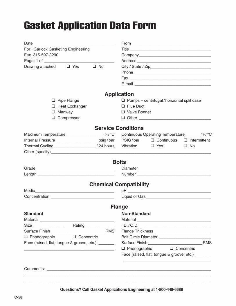
Gasket Application Data Form
Date ____________________________________ From ___________________________________For: Garlock Gasketing Engineering Title ____________________________________Fax 315-597-3290 Company ________________________________Page: 1 of _______________________________ Address _________________________________Drawing attached ❑ Yes ❑ No City / State / Zip ___________________________ Phone __________________________________ Fax ____________________________________ E-mail __________________________________
Application ❑ Pipe Flange ❑ Pumps – centrifugal / horizontal split case ❑ Heat Exchanger ❑ Flue Duct ❑ Manway ❑ Valve Bonnet ❑ Compressor ❑ Other ________________________________
Service ConditionsMaximum Temperature ________________ °F / °C Continuous Operating Temperature ______ °F / °CInternal Pressure ___________________psig / bar PSIG / bar ❑ Continuous ❑ IntermittentThermal Cycling ___________________/ 24 hours Vibration ❑ Yes ❑ NoOther (specify) _______________________________________________________________________
BoltsGrade ___________________________________ Diameter ________________________________Length __________________________________ Number _________________________________
Chemical CompatibilityMedia ___________________________________ pH _____________________________________Concentration ____________________________ Liquid or Gas _____________________________
FlangeStandard Non-StandardMaterial _________________________________ Material _________________________________Size ______________ Rating _____________ I.D. / O.D. ________________________________Surface Finish ________________________RMS Flange Thickness _________________________❑ Phonographic ❑ Concentric Bolt Circle Diameter _______________________Face (raised, flat, tongue & groove, etc.) _______ Surface Finish ________________________RMS________________________________________ ❑ Phonographic ❑ Concentric Face (raised, flat, tongue & groove, etc.) _______ _______________________________________
Comments: _________________________________________________________________________ ______________________________________________________________________________________________________________________________________________________________________
Questions? Call Gasket Applications Engineering at 1-800-448-6688
C-58
• ISO 9001:2000 registration for Industrial Gasketing, Industrial Packing, KLOZURE®
Oil Seals, Bearing Protectors, and Mechani-cal Seals, Expansion Joints, Hydraulic Com-ponents,and Industrial Rubber Products.
• A global network of stocking Authorized Gar-lock Distributors.
• Factory sales representatives and applica-tions engineers available for problem solving when and where it is needed.
• Toll-free 800 telephone and fax numbers for immediate product information.
• In-plant surveys of equipment and processes, providing the customer with recommenda-tions to identify and eliminate sealing and packing problems before they start.
More than just great products…Beyond offering you the widest available range of products for packing and sealing, Garlock enhances the value of its products with technical services and comprehensive training programs:
• The most sophisticated and most compre-hensive test facilities available.
• Technical fi eld seminars on all Garlock prod-ucts.
• Factory-sponsored product training pro-grams, including hands-on seminars, to ensure that Garlock representatives and their distributor personnel are the best in the industry.
• Technical Bulletins to keep you up-to-date on product enhancements and changes.
Customers who specify Garlock fl uid sealing products get, at no extra cost, the high quality support needed to run a profi table operation.
AUTHORIZED REPRESENTATIVE
Other Garlock facilities are located in:Columbia, SC, USA Houston, TX, USA Sydney, AustraliaPhone 1.803.783.1880 Phone 1.281.459.7200 Phone 61.2.9793.2511Fax 1.803.783.4279 Fax 1.281.458.0502 Fax 61.2.9793.2544São Paulo, Brazil Sherbrooke, Canada W. Yorkshire, EnglandPhone 55.11.4352.6161 Phone 1.819.563.8080 Phone 44.1422.313600Fax 55.11.4352.8181 Fax 1.819-563.5620 Fax 44.1422.313601Saint-Étienne, France Neuss, Germany Mexico City, MexicoPhone 33.4.7743.5100 Phone 49.2131.3490 Phone 52.555.567.7011Fax 33.4.7743.5151 Fax 49.2131.349.222 Fax 52.555.368.0418Singapore Shanghai, China Dubai, UAEPhone 65.6285.9322 Phone 86.021.62789702 Phone 971.4.8833652Fax 65.6284.5843 Fax 86.021.62787826 Fax 971.4.8833682
WARNING:Properties/applications shown throughout this brochure are typical. Your specific application should not be undertaken without independent study and evaluation for suitability. For specific application recommendations consult Garlock. Failure to select the proper sealing products could result in property damage and/or serious personal injury. Performance data published in this brochure has been developed from field testing, customer field reports and/or in-house testing.While the utmost care has been used in compiling this brochure, we assume no responsibility for errors. Specifications subject to change without notice. This edition cancels all previous issues. Subject to change without notice.GARLOCK is a registered trademark for packings, seals, gaskets, and other products of Garlock.© Garlock Inc 2007. All rights reserved worldwide.
PRINTED IN U.S.A. GSK 3:1 VIA-2/07-C
Garlock Sealing Technologies1666 Division StreetPalmyra, New York 14522 USA1-315-597-48111-800-448-6688Fax: 1-800-543-05981-315-597-3039
www.garlock.com