Embed Size (px)
Citation preview
6
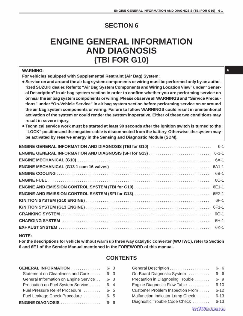
ENGINE GENERAL INFORMATION AND DIAGNOSIS (TBI FOR G10) 6-1
GENERAL INFORMATION 6- 3. . . . . . . . . . . . . . Statement on Cleanliness and Care 6- 3. . . . . General Information on Engine Service 6- 3. . Precaution on Fuel System Service 6- 4. . . . . Fuel Pressure Relief Procedure 6- 5. . . . . . . . Fuel Leakage Check Procedure 6- 5. . . . . . . .
ENGINE DIAGNOSIS 6- 6. . . . . . . . . . . . . . . . . . .
General Description 6- 6. . . . . . . . . . . . . . . . . . . On-Board Diagnostic System 6- 6. . . . . . . . . . Precaution in Diagnosing Trouble 6- 9. . . . . . . Engine Diagnostic Flow Table 6-10. . . . . . . . . . Customer Problem Inspection From 6-12. . . . . Malfunction Indicator Lamp Check 6-13. . . . . . Diagnostic Trouble Code Check 6-13. . . . . . . .
SECTION 6
ENGINE GENERAL INFORMATIONAND DIAGNOSIS
(TBI FOR G10)WARNING:For vehicles equipped with Supplemental Restraint (Air Bag) System: Service on and around the air bag system components or wiring must be performed only by an autho-
rized SUZUKI dealer. Refer to “Air Bag System Components and Wiring Location View” under “Gener-al Description” in air bag system section in order to confirm whether you are performing service onor near the air bag system components or wiring. Please observe all WARNINGS and “Service Precau-tions” under “On-Vehicle Service” in air bag system section before performing service on or aroundthe air bag system components or wiring. Failure to follow WARNINGS could result in unintentionalactivation of the system or could render the system inoperative. Either of these two conditions mayresult in severe injury.
Technical service work must be started at least 90 seconds after the ignition switch is turned to the“LOCK” position and the negative cable is disconnected from the battery. Otherwise, the system maybe activated by reserve energy in the Sensing and Diagnostic Module (SDM).
ENGINE GENERAL INFORMATION AND DIAGNOSIS (TBI for G10) 6-1. . . . . . . . . . . . . . . . . . . . . . . . . . . . .
ENGINE GENERAL INFORMATION AND DIAGNOSIS (SFI for G13) 6-1-1. . . . . . . . . . . . . . . . . . . . . . . . . . . . .
ENGINE MECHANICAL (G10) 6A-1. . . . . . . . . . . . . . . . . . . . . . . . . . . . . . . . . . . . . . . . . . . . . . . . . . . . . . . . . . . . . . .
ENGINE MECHANICAL (G13 1 cam 16 valves) 6A1-1. . . . . . . . . . . . . . . . . . . . . . . . . . . . . . . . . . . . . . . . . . . . . . .
ENGINE COOLING 6B-1. . . . . . . . . . . . . . . . . . . . . . . . . . . . . . . . . . . . . . . . . . . . . . . . . . . . . . . . . . . . . . . . . . . . . . . . .
ENGINE FUEL 6C-1. . . . . . . . . . . . . . . . . . . . . . . . . . . . . . . . . . . . . . . . . . . . . . . . . . . . . . . . . . . . . . . . . . . . . . . . . . . . .
ENGINE AND EMISSION CONTROL SYSTEM (TBI for G10) 6E1-1. . . . . . . . . . . . . . . . . . . . . . . . . . . . . . . . . . . .
ENGINE AND EMISSION CONTROL SYSTEM (SFI for G13) 6E2-1. . . . . . . . . . . . . . . . . . . . . . . . . . . . . . . . . . . .
IGNITION SYSTEM (G10 ENGINE) 6F-1. . . . . . . . . . . . . . . . . . . . . . . . . . . . . . . . . . . . . . . . . . . . . . . . . . . . . . . . . . .
IGNITION SYSTEM (G13 ENGINE) 6F1-1. . . . . . . . . . . . . . . . . . . . . . . . . . . . . . . . . . . . . . . . . . . . . . . . . . . . . . . . . . .
CRANKING SYSTEM 6G-1. . . . . . . . . . . . . . . . . . . . . . . . . . . . . . . . . . . . . . . . . . . . . . . . . . . . . . . . . . . . . . . . . . . . . . .
CHARGING SYSTEM 6H-1. . . . . . . . . . . . . . . . . . . . . . . . . . . . . . . . . . . . . . . . . . . . . . . . . . . . . . . . . . . . . . . . . . . . . .
EXHAUST SYSTEM 6K-1. . . . . . . . . . . . . . . . . . . . . . . . . . . . . . . . . . . . . . . . . . . . . . . . . . . . . . . . . . . . . . . . . . . . . . . .
NOTE:For the descriptions for vehicle without warm up three way catalytic converter (WUTWC), refer to Section6 and 6E1 of the Service Manual mentioned in the FOREWORD of this manual.
CONTENTS
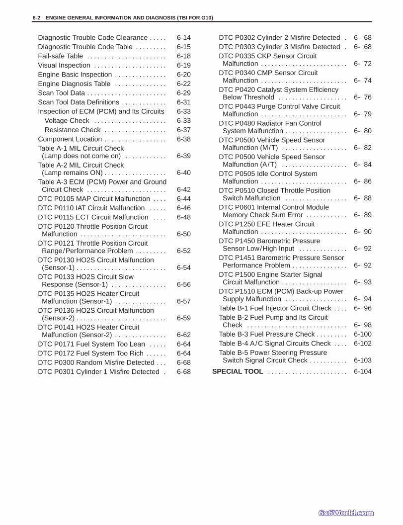
Diagnostic Trouble Code Clearance 6-14. . . . . Diagnostic Trouble Code Table 6-15. . . . . . . . . Fail-safe Table 6-18. . . . . . . . . . . . . . . . . . . . . . . Visual Inspection 6-19. . . . . . . . . . . . . . . . . . . . . Engine Basic Inspection 6-20. . . . . . . . . . . . . . . Engine Diagnosis Table 6-22. . . . . . . . . . . . . . . Scan Tool Data 6-29. . . . . . . . . . . . . . . . . . . . . . . Scan Tool Data Definitions 6-31. . . . . . . . . . . . . Inspection of ECM (PCM) and Its Circuits 6-33
Voltage Check 6-33. . . . . . . . . . . . . . . . . . . . . Resistance Check 6-37. . . . . . . . . . . . . . . . . .
Component Location 6-38. . . . . . . . . . . . . . . . . . Table A-1 MIL Circuit Check
(Lamp does not come on) 6-39. . . . . . . . . . . . Table A-2 MIL Circuit Check
(Lamp remains ON) 6-40. . . . . . . . . . . . . . . . . . Table A-3 ECM (PCM) Power and Ground
Circuit Check 6-42. . . . . . . . . . . . . . . . . . . . . . . DTC P0105 MAP Circuit Malfunction 6-44. . . . DTC P0110 IAT Circuit Malfunction 6-46. . . . . DTC P0115 ECT Circuit Malfunction 6-48. . . . DTC P0120 Throttle Position Circuit
Malfunction 6-50. . . . . . . . . . . . . . . . . . . . . . . . . DTC P0121 Throttle Position Circuit
Range/Performance Problem 6-52. . . . . . . . . DTC P0130 HO2S Circuit Malfunction
(Sensor-1) 6-54. . . . . . . . . . . . . . . . . . . . . . . . . . DTC P0133 HO2S Circuit Slow
Response (Sensor-1) 6-56. . . . . . . . . . . . . . . . DTC P0135 HO2S Heater Circuit
Malfunction (Sensor-1) 6-57. . . . . . . . . . . . . . . DTC P0136 HO2S Circuit Malfunction
(Sensor-2) 6-59. . . . . . . . . . . . . . . . . . . . . . . . . . DTC P0141 HO2S Heater Circuit
Malfunction (Sensor-2) 6-62. . . . . . . . . . . . . . . DTC P0171 Fuel System Too Lean 6-64. . . . . DTC P0172 Fuel System Too Rich 6-64. . . . . . DTC P0300 Random Misfire Detected 6-68. . . DTC P0301 Cylinder 1 Misfire Detected 6-68.
DTC P0302 Cylinder 2 Misfire Detected 6- 68. DTC P0303 Cylinder 3 Misfire Detected 6- 68. DTC P0335 CKP Sensor Circuit
Malfunction 6- 72. . . . . . . . . . . . . . . . . . . . . . . . . DTC P0340 CMP Sensor Circuit
Malfunction 6- 74. . . . . . . . . . . . . . . . . . . . . . . . . DTC P0420 Catalyst System Efficiency
Below Threshold 6- 76. . . . . . . . . . . . . . . . . . . . DTC P0443 Purge Control Valve Circuit
Malfunction 6- 79. . . . . . . . . . . . . . . . . . . . . . . . . DTC P0480 Radiator Fan Control
System Malfunction 6- 80. . . . . . . . . . . . . . . . . . DTC P0500 Vehicle Speed Sensor
Malfunction (M/T) 6- 82. . . . . . . . . . . . . . . . . . . DTC P0500 Vehicle Speed Sensor
Malfunction (A/T) 6- 84. . . . . . . . . . . . . . . . . . . DTC P0505 Idle Control System
Malfunction 6- 86. . . . . . . . . . . . . . . . . . . . . . . . . DTC P0510 Closed Throttle Position
Switch Malfunction 6- 88. . . . . . . . . . . . . . . . . . DTC P0601 Internal Control Module
Memory Check Sum Error 6- 89. . . . . . . . . . . . DTC P1250 EFE Heater Circuit
Malfunction 6- 90. . . . . . . . . . . . . . . . . . . . . . . . . DTC P1450 Barometric Pressure
Sensor Low/High Input 6- 92. . . . . . . . . . . . . . DTC P1451 Barometric Pressure Sensor
Performance Problem 6- 92. . . . . . . . . . . . . . . . DTC P1500 Engine Starter Signal
Circuit Malfunction 6- 93. . . . . . . . . . . . . . . . . . . DTC P1510 ECM (PCM) Back-up Power
Supply Malfunction 6- 94. . . . . . . . . . . . . . . . . . Table B-1 Fuel Injector Circuit Check 6- 96. . . . Table B-2 Fuel Pump and Its Circuit
Check 6- 98. . . . . . . . . . . . . . . . . . . . . . . . . . . . . Table B-3 Fuel Pressure Check 6-100. . . . . . . . . Table B-4 A/C Signal Circuits Check 6-102. . . . Table B-5 Power Steering Pressure
Switch Signal Circuit Check 6-103. . . . . . . . . . .
SPECIAL TOOL 6-104. . . . . . . . . . . . . . . . . . . . . . .
6-2 ENGINE GENERAL INFORMATION AND DIAGNOSIS (TBI FOR G10)
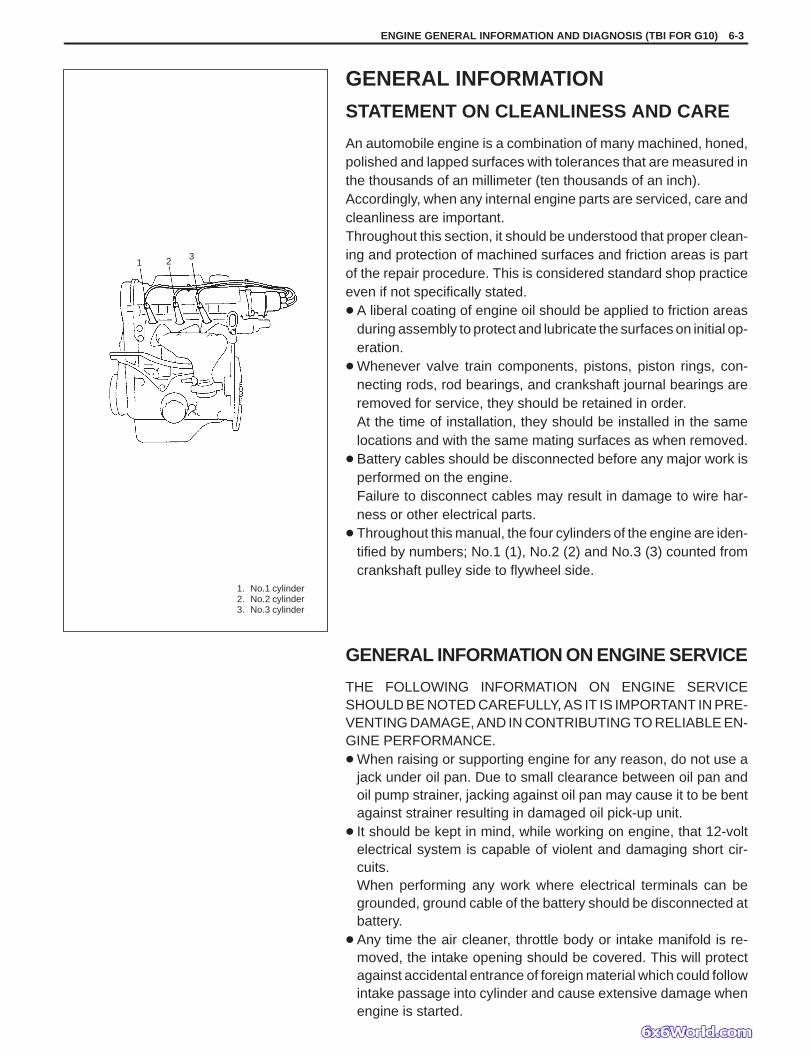
1. No.1 cylinder2. No.2 cylinder3. No.3 cylinder
1 2 3
ENGINE GENERAL INFORMATION AND DIAGNOSIS (TBI FOR G10) 6-3
GENERAL INFORMATION
STATEMENT ON CLEANLINESS AND CARE
An automobile engine is a combination of many machined, honed,polished and lapped surfaces with tolerances that are measured inthe thousands of an millimeter (ten thousands of an inch).Accordingly, when any internal engine parts are serviced, care andcleanliness are important.Throughout this section, it should be understood that proper clean-ing and protection of machined surfaces and friction areas is partof the repair procedure. This is considered standard shop practiceeven if not specifically stated. A liberal coating of engine oil should be applied to friction areas
during assembly to protect and lubricate the surfaces on initial op-eration.
Whenever valve train components, pistons, piston rings, con-necting rods, rod bearings, and crankshaft journal bearings areremoved for service, they should be retained in order.At the time of installation, they should be installed in the samelocations and with the same mating surfaces as when removed.
Battery cables should be disconnected before any major work isperformed on the engine.Failure to disconnect cables may result in damage to wire har-ness or other electrical parts.
Throughout this manual, the four cylinders of the engine are iden-tified by numbers; No.1 (1), No.2 (2) and No.3 (3) counted fromcrankshaft pulley side to flywheel side.
GENERAL INFORMATION ON ENGINE SERVICE
THE FOLLOWING INFORMATION ON ENGINE SERVICESHOULD BE NOTED CAREFULLY, AS IT IS IMPORTANT IN PRE-VENTING DAMAGE, AND IN CONTRIBUTING TO RELIABLE EN-GINE PERFORMANCE. When raising or supporting engine for any reason, do not use a
jack under oil pan. Due to small clearance between oil pan andoil pump strainer, jacking against oil pan may cause it to be bentagainst strainer resulting in damaged oil pick-up unit.
It should be kept in mind, while working on engine, that 12-voltelectrical system is capable of violent and damaging short cir-cuits.When performing any work where electrical terminals can begrounded, ground cable of the battery should be disconnected atbattery.
Any time the air cleaner, throttle body or intake manifold is re-moved, the intake opening should be covered. This will protectagainst accidental entrance of foreign material which could followintake passage into cylinder and cause extensive damage whenengine is started.
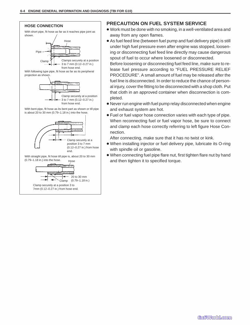
HOSE CONNECTION
Clamp securely at a position 3 to7mm (0.12–0.27 in.) from hose end.
With short pipe, fit hose as far as it reaches pipe joint asshown.
Hose
Pipe
Clamp Clamps securely at a position3 to 7 mm (0.12–0.27 in.)from hose end.
With following type pipe, fit hose as far as its peripheralprojection as shown.
Clamp securely at a position3 to 7 mm (0.12–0.27 in.)from hose end.
With bent pipe, fit hose as its bent part as shown or till pipeis about 20 to 30 mm (0.79–1.18 in.) into the hose.
Clamp securely at aposition 3 to 7 mm(0.12–0.27 in.) from hoseend.
With straight pipe, fit hose till pipe is, about 20 to 30 mm(0.79–1.18 in.) into the hose. Hose
20 to 30 mm(0.79–1.18 in.)Clamp
6-4 ENGINE GENERAL INFORMATION AND DIAGNOSIS (TBI FOR G10)
PRECAUTION ON FUEL SYSTEM SERVICE Work must be done with no smoking, in a well-ventilated area and
away from any open flames. As fuel feed line (between fuel pump and fuel delivery pipe) is still
under high fuel pressure even after engine was stopped, loosen-ing or disconnecting fuel feed line directly may cause dangerousspout of fuel to occur where loosened or disconnected.Before loosening or disconnecting fuel feed line, make sure to re-lease fuel pressure according to “FUEL PRESSURE RELIEFPROCEDURE”. A small amount of fuel may be released after thefuel line is disconnected. In order to reduce the chance of person-al injury, cover the fitting to be disconnected with a shop cloth. Putthat cloth in an approved container when disconnection is com-pleted.
Never run engine with fuel pump relay disconnected when engineand exhaust system are hot.
Fuel or fuel vapor hose connection varies with each type of pipe.When reconnecting fuel or fuel vapor hose, be sure to connectand clamp each hose correctly referring to left figure Hose Con-nection.After connecting, make sure that it has no twist or kink.
When installing injector or fuel delivery pipe, lubricate its O-ringwith spindle oil or gasoline.
When connecting fuel pipe flare nut, first tighten flare nut by handand then tighten it to specified torque.
ENGINE GENERAL INFORMATION AND DIAGNOSIS (TBI FOR G10) 6-5
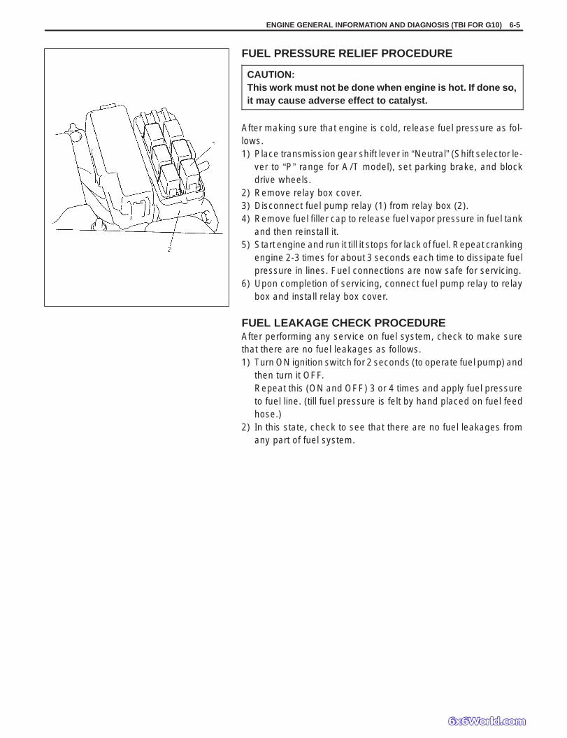
FUEL PRESSURE RELIEF PROCEDURE
CAUTION:This work must not be done when engine is hot. If done so,it may cause adverse effect to catalyst.
After making sure that engine is cold, release fuel pressure as fol-lows.1) Place transmission gear shift lever in “Neutral” (Shift selector le-
ver to “P” range for A/T model), set parking brake, and blockdrive wheels.
2) Remove relay box cover.3) Disconnect fuel pump relay (1) from relay box (2).4) Remove fuel filler cap to release fuel vapor pressure in fuel tank
and then reinstall it.5) Start engine and run it till it stops for lack of fuel. Repeat cranking
engine 2-3 times for about 3 seconds each time to dissipate fuelpressure in lines. Fuel connections are now safe for servicing.
6) Upon completion of servicing, connect fuel pump relay to relaybox and install relay box cover.
FUEL LEAKAGE CHECK PROCEDUREAfter performing any service on fuel system, check to make surethat there are no fuel leakages as follows.1) Turn ON ignition switch for 2 seconds (to operate fuel pump) and
then turn it OFF.Repeat this (ON and OFF) 3 or 4 times and apply fuel pressureto fuel line. (till fuel pressure is felt by hand placed on fuel feedhose.)
2) In this state, check to see that there are no fuel leakages fromany part of fuel system.
6-6 ENGINE GENERAL INFORMATION AND DIAGNOSIS (TBI FOR G10)
ENGINE DIAGNOSIS
GENERAL DESCRIPTION
This vehicle is equipped with an engine and emission control system which are under control of ECM (PCM).The engine and emission control system in this vehicle are controlled by ECM (PCM). ECM (PCM) has an On-Board Diagnostic system which detects a malfunction in this system and abnormality of those parts that influencethe engine exhaust emission. When diagnosing engine troubles, be sure to have full understanding of the outlineof “On-Board Diagnostic System” and each item in “Precaution in Diagnosing Trouble” and execute diagnosis ac-cording to “ENGINE DIAGNOSTIC FLOW TABLE”.There is a close relationship between the engine mechanical, engine cooling system, ignition system, exhaust sys-tem, etc. and the engine and emission control system in their structure and operation. In case of an engine trouble,even when the malfunction indicator lamp (MIL) doesn’t turn ON, it should be diagnosed according to this flow table.
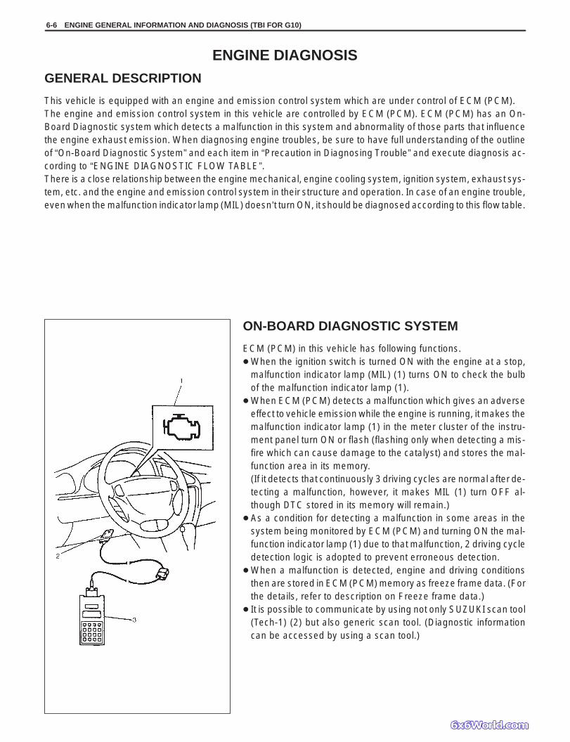
ON-BOARD DIAGNOSTIC SYSTEM
ECM (PCM) in this vehicle has following functions. When the ignition switch is turned ON with the engine at a stop,
malfunction indicator lamp (MIL) (1) turns ON to check the bulbof the malfunction indicator lamp (1).
When ECM (PCM) detects a malfunction which gives an adverseeffect to vehicle emission while the engine is running, it makes themalfunction indicator lamp (1) in the meter cluster of the instru-ment panel turn ON or flash (flashing only when detecting a mis-fire which can cause damage to the catalyst) and stores the mal-function area in its memory.(If it detects that continuously 3 driving cycles are normal after de-tecting a malfunction, however, it makes MIL (1) turn OFF al-though DTC stored in its memory will remain.)
As a condition for detecting a malfunction in some areas in thesystem being monitored by ECM (PCM) and turning ON the mal-function indicator lamp (1) due to that malfunction, 2 driving cycledetection logic is adopted to prevent erroneous detection.
When a malfunction is detected, engine and driving conditionsthen are stored in ECM (PCM) memory as freeze frame data. (Forthe details, refer to description on Freeze frame data.)
It is possible to communicate by using not only SUZUKI scan tool(Tech-1) (2) but also generic scan tool. (Diagnostic informationcan be accessed by using a scan tool.)
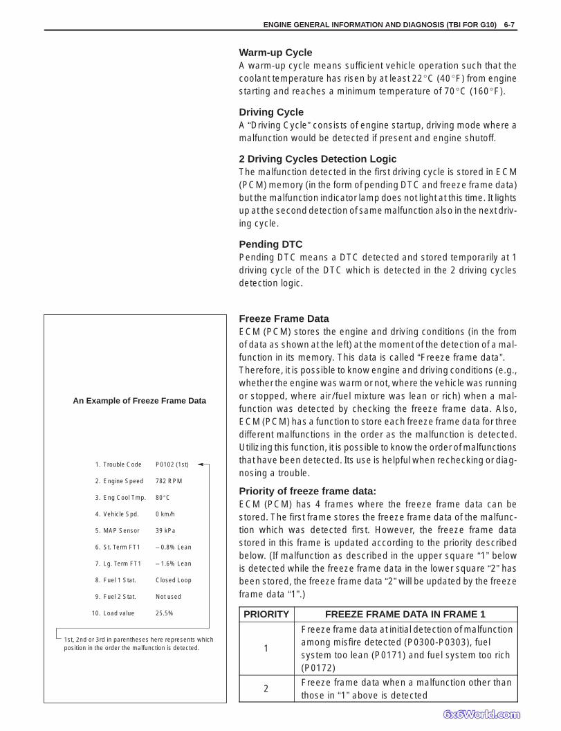
An Example of Freeze Frame Data
1. Trouble Code P0102 (1st)
2. Engine Speed 782 RPM
3. Eng Cool Tmp. 80C
4. Vehicle Spd. 0 km/h
5. MAP Sensor 39 kPa
6. St. Term FT1 – 0.8% Lean
7. Lg. Term FT1 – 1.6% Lean
8. Fuel 1 Stat. Closed Loop
9. Fuel 2 Stat. Not used
10. Load value 25.5%
1st, 2nd or 3rd in parentheses here represents whichposition in the order the malfunction is detected.
ENGINE GENERAL INFORMATION AND DIAGNOSIS (TBI FOR G10) 6-7
Warm-up CycleA warm-up cycle means sufficient vehicle operation such that thecoolant temperature has risen by at least 22C (40F) from enginestarting and reaches a minimum temperature of 70C (160F).
Driving CycleA “Driving Cycle” consists of engine startup, driving mode where amalfunction would be detected if present and engine shutoff.
2 Driving Cycles Detection LogicThe malfunction detected in the first driving cycle is stored in ECM(PCM) memory (in the form of pending DTC and freeze frame data)but the malfunction indicator lamp does not light at this time. It lightsup at the second detection of same malfunction also in the next driv-ing cycle.
Pending DTCPending DTC means a DTC detected and stored temporarily at 1driving cycle of the DTC which is detected in the 2 driving cyclesdetection logic.
Freeze Frame DataECM (PCM) stores the engine and driving conditions (in the fromof data as shown at the left) at the moment of the detection of a mal-function in its memory. This data is called “Freeze frame data”.Therefore, it is possible to know engine and driving conditions (e.g.,whether the engine was warm or not, where the vehicle was runningor stopped, where air / fuel mixture was lean or rich) when a mal-function was detected by checking the freeze frame data. Also,ECM (PCM) has a function to store each freeze frame data for threedifferent malfunctions in the order as the malfunction is detected.Utilizing this function, it is possible to know the order of malfunctionsthat have been detected. Its use is helpful when rechecking or diag-nosing a trouble.
Priority of freeze frame data:ECM (PCM) has 4 frames where the freeze frame data can bestored. The first frame stores the freeze frame data of the malfunc-tion which was detected first. However, the freeze frame datastored in this frame is updated according to the priority describedbelow. (If malfunction as described in the upper square “1” belowis detected while the freeze frame data in the lower square “2” hasbeen stored, the freeze frame data “2” will be updated by the freezeframe data “1”.)
PRIORITY FREEZE FRAME DATA IN FRAME 1
1
Freeze frame data at initial detection of malfunctionamong misfire detected (P0300-P0303), fuelsystem too lean (P0171) and fuel system too rich(P0172)
2Freeze frame data when a malfunction other thanthose in “1” above is detected
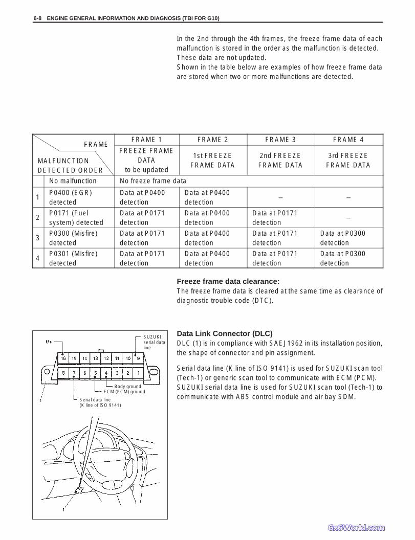
Body groundECM (PCM) ground
Serial data line (K line of ISO 9141)
SUZUKIserial dataline
6-8 ENGINE GENERAL INFORMATION AND DIAGNOSIS (TBI FOR G10)
In the 2nd through the 4th frames, the freeze frame data of eachmalfunction is stored in the order as the malfunction is detected.These data are not updated.Shown in the table below are examples of how freeze frame dataare stored when two or more malfunctions are detected.
FRAMEFRAME 1 FRAME 2 FRAME 3 FRAME 4
FRAME
MALFUNCTIONDETECTED ORDER
FREEZE FRAMEDATA
to be updated
1st FREEZEFRAME DATA
2nd FREEZEFRAME DATA
3rd FREEZEFRAME DATA
No malfunction No freeze frame data
1P0400 (EGR)detected
Data at P0400detection
Data at P0400detection
– –
2P0171 (Fuelsystem) detected
Data at P0171detection
Data at P0400detection
Data at P0171detection
–
3P0300 (Misfire)detected
Data at P0171detection
Data at P0400detection
Data at P0171detection
Data at P0300detection
4P0301 (Misfire)detected
Data at P0171detection
Data at P0400detection
Data at P0171detection
Data at P0300detection
Freeze frame data clearance:The freeze frame data is cleared at the same time as clearance ofdiagnostic trouble code (DTC).
Data Link Connector (DLC)DLC (1) is in compliance with SAEJ1962 in its installation position,the shape of connector and pin assignment.
Serial data line (K line of ISO 9141) is used for SUZUKI scan tool(Tech-1) or generic scan tool to communicate with ECM (PCM).SUZUKI serial data line is used for SUZUKI scan tool (Tech-1) tocommunicate with ABS control module and air bay SDM.

ENGINE GENERAL INFORMATION AND DIAGNOSIS (TBI FOR G10) 6-9
PRECAUTION IN DIAGNOSING TROUBLE
Don’t disconnect couplers from ECM (PCM), battery cable frombattery, ECM (PCM) ground wire harness from engine or mainfuse before confirming diagnostic information (DTC, freeze framedata, etc.) stored in ECM (PCM) memory. Such disconnection willerase memorized information in ECM (PCM) memory.
Diagnostic information stored in ECM (PCM) memory can becleared as well as checked by using SUZUKI scan tool (Tech-1)or generic scan tool. Before using scan tool, read its Operator’s(Instruction) Manual carefully to have good understanding as towhat functions are available and how to use it.
Priorities for diagnosing troubles.If two or more DTCs are stored, proceed to the flow table of theDTC which has detected earliest in the order and follow theinstruction in that table.If no instructions are given, troubleshoot diagnostic trouble codesaccording to the following priorities.1. Diagnostic trouble codes (DTCs) other than DTC P0171/
P0172 (Fuel system too lean/too rich) and DTC P0300/P0301/P0302/P0303 (Misfire detected)
2. DTC P0171/P0172 (Fuel system too lean/too rich)3. DTC P0300/P0301/P0302/P0303 (Misfire detected)
Be sure to read “Precautions for Electrical Circuit Service” in Sec-tion 0A before inspection and observe what is written there.
ECM (PCM) ReplacementWhen substituting a known-good ECM (PCM), check for followingconditions. Neglecting this check may cause damage to a known-good ECM (PCM).– Resistance value of all relays, actuators is as specified respec-
tively.– MAP sensor and TP sensor are in good condition and none of
power circuits of these sensors is shorted to ground.

6-10 ENGINE GENERAL INFORMATION AND DIAGNOSIS (TBI FOR G10)
ENGINE DIAGNOSTIC FLOW TABLE
Refer to the following pages for the details of each step.
STEP ACTION YES NO
1 Customer Complaint Analysis1) Perform customer complaint analysis referring to the
next page.Was customer complaint analysis performed?
Go to Step 2. Perform customercomplaint analysis.
2 Diagnostic Trouble Code (DTC) and Freeze Frame DataCheck, Record and Clearance1) Check for DTC (including pending DTC) referring to
the next page.Is there any DTC(s)?
1) Print DTC andfreeze frame dataor write themdown and clearthem by referringto “DTCClearance”section.
2) Go to Step 3.
Go to Step 4.
3 Visual Inspection1) Perform visual inspection referring to the next page.Is there any faulty condition?
1) Repair or replacemalfunction part.
2) Go to Step 11.
Go to Step 5.
4 Visual Inspection1) Perform visual inspection referring to the next page.Is there any faulty condition?
Go to Step 8.
5 Trouble Symptom Confirmation1) Confirm trouble symptom referring to the next page.Is trouble symptom identified?
Go to Step 6. Go to Step 7.
6 Rechecking and Record of DTC/Freeze Frame Data1) Recheck for DTC and freeze frame data referring to
“DTC Check” section.Is there any DTC(s)?
Go to Step 9. Go to Step 8.
7 Rechecking and Record of DTC/Freeze Frame Data1) Recheck for DTC and freeze frame data referring to
“DTC Check” section.Is there any DTC(s)?
Go to Step 10.
8 Engine Basic Inspection and Engine Diag. Table1) Check and repair according to “Engine Basic Check”
and “Engine Diag. Table” section.Are check and repair complete?
Go to Step 11. 1) Check and repairmalfunctionpart(s).
2) Go to Step 11.
9 Trouble shooting for DTC1) Check and repair according to applicable DTC diag.
flow table.Are check and repair complete?
10 Check for Intermittent Problems1) Check for intermittent problems referring to the next
page.Is there any faulty condition?
1) Repair or replacemalfunctionpart(s).
2) Go to Step 11.
Go to Step 11.
11 Final Confirmation Test1) Clear DTC if any.2) Perform final confirmation test referring to the next
page.Is there any problem symptom, DTC or abnormalcondition?
Go to Step 6. End.

ENGINE GENERAL INFORMATION AND DIAGNOSIS (TBI FOR G10) 6-11
1. CUSTOMER COMPLAINT ANALYSISRecord details of the problem (failure, complaint) and how it occurred as described by the customer. For thispurpose, use of such an inspection form will facilitate collecting information to the point required for properanalysis and diagnosis.
2. DIAGNOSTIC TROUBLE CODE (DTC)/FREEZE FRAME DATA CHECK, RECORD ANDCLEARANCEFirst, check DTC (including pending DTC), referring to “DTC check” section. If DTC is indicated, print it andfreeze frame data or write them down and then clear them by referring to “DTC clearance” section. DTC indi-cates malfunction that occurred in the system but does not indicate whether it exists now or it occurred in thepast and the normal condition has been restored now. To check which case applies, check the symptom inquestion according to Step 4 and recheck DTC according to Step 5.Attempt to diagnose a trouble based on DTC in this step only or failure to clear the DTC in this step will leadto incorrect diagnosis, trouble diagnosis of a normal circuit or difficulty in troubleshooting.
NOTE:If only Automatic transmission DTCs (P0705/P0720/P0753/P0758/P0751/P0756) or ImmobilizerDTCs (P1620 – P1623) are indicated in this step, perform trouble diagnosis according to “Diagnosis”in Section 7B or Section 8G.
3. and 4. VISUAL INSPECTIONAs a preliminary step, be sure to perform visual check of the items that support proper function of the enginereferring to “Visual Inspection” section.
5. TROUBLE SYMPTOM CONFIRMATIONBased on information obtained in Step 1 Customer complaint analysis and Step 2 DTC/freeze frame datacheck, confirm trouble symptoms. Also, reconfirm DTC according to “DTC Confirmation Procedure” describedin each DTC Diagnosis section.
6. and 7. RECHECKING AND RECORD OF DTC/FREEZE FRAME DATARefer to “DTC check” section for checking procedure.
8. ENGINE BASIC INSPECTION AND ENGINE DIAGNOSIS TABLEPerform basic engine check according to the “Engine Basic Inspection Flow Table” first. When the end of theflow table has been reached, check the parts of the system suspected as a possible cause referring to ENGINEDIAGNOSIS FLOW TABLE and based on symptoms appearing on the vehicle (symptoms obtained throughsteps of customer complaint analysis, trouble symptom confirmation and/or basic engine check) and repairor replace faulty parts, if any.
9. TROUBLESHOOTING FOR DTC (See each DTC Diag. Flow Table)Based on the DTC indicated in Step 5 and referring to the applicable DTC diag. flow table in this section, locatethe cause of the trouble, namely in a sensor, switch, wire harness, connector, actuator, ECM (PCM) or otherpart and repair or replace faulty parts.
10. CHECK FOR INTERMITTENT PROBLEMCheck parts where an intermittent trouble is easy to occur (e.g., wire harness, connector, etc.), referring to“INTERMITTENT AND POOR CONNECTION” in Section 0A and related circuit of DTC recorded in Step 2.
11. FINAL CONFIRMATION TESTConfirm that the problem symptom has gone and the engine is free from any abnormal conditions. If what hasbeen repaired is related to the DTC, clear the DTC once, perform DTC confirmation procedure and confirmthat no DTC is indicated.

6-12 ENGINE GENERAL INFORMATION AND DIAGNOSIS (TBI FOR G10)
CUSTOMER PROBLEM INSPECTION FORM (EXAMPLE)
User name: Model: VIN:
Date of issue: Date Reg. Date of problem: Mileage:
PROBLEM SYMPTOMS
Difficult Starting No cranking No initial combustion No combustion Poor starting at
(cold warm always) Other
Poor Driveability Hesitation on acceleration Back fire/After fire Lack of power Surging abnormal knocking Other
Poor Idling Poor fast idle Abnormal idling speed
(High Low) ( r /min.) Unstable Hunting ( r /min. to r /min.) Other
Engine Stall when Immediately after start Accel. pedal is depressed Accel. pedal is released Load is applied
A/C Electric load P/S Other
Other
OTHERS:
VEHICLE/ENVIRONMENTAL CONDITION WHEN PROBLEM OCCURS
Environmental Condition
WeatherTemperatureFrequencyRoad
Fair Cloudy Rain Snow Always OtherHot Warm Cool Cold ( F/ C) AlwaysAlways Sometimes ( times/ day, month) Only once Under certain conditionUrban Suburb Highway Mountainous (Uphill Downhill) Tarmacadam GravelOther
Vehicle Condition
Enginecondition
Cold Warming up phase Warmed up Always Other at startingImmediately after start Racing without load Engine speed ( r /min.)
Vehiclecondition
During driving: Constant speed Accelerating DeceleratingRight hand corner Left hand corner When shifting (Lever position ) At stopVehicle speed when problem occurs ( km/h, Mile/h) Other
Malfunction indicatorlamp condition Always ON Sometimes ON Always OFF Good condition
Diagnostic trouble First check: No code Malfunction code ( )gcode Second check: No code Malfunction code ( )
NOTE:The above form is a standard sample. It should be modified according to conditions characteristic of eachmarket.

ENGINE GENERAL INFORMATION AND DIAGNOSIS (TBI FOR G10) 6-13
MALFUNCTION INDICATOR LAMP (MIL)CHECK
1) Turn ON ignition switch (but the engine at stop) and check thatMIL lights.If MIL does not light up (or MIL dims), go to “Diagnostic FlowTable A-1” for troubleshooting.
2) Start engine and check that MIL turns OFF.If MIL remains ON and no DTC is stored in ECM (PCM), go to“Diagnostic Flow Table A-2” for troubleshooting.
DIAGNOSTIC TROUBLE CODE (DTC) CHECK
1) Prepare SUZUKI scan tool (Tech-1) or generic scan tool.2) With ignition switch OFF, connect it to data link connector (DLC)
(1) located on underside of instrument panel at driver’s seat side.
Special Tool:(A): SUZUKI scan tool(B): Mass storage cartridge(C): 16/14 pin DLC cable
3) Turn ignition switch ON and confirm that MIL lights.4) Read DTC, pending DTC and freeze frame data according to
instructions displayed on scan tool and print it or write it down.Refer to scan tool operator’s manual for further details.If communication between scan tool and ECM (PCM) is not pos-sible, check if scan tool is communicable by connecting it toECM (PCM) in another vehicle. If communication is possible inthis case, scan tool is in good condition. Then check data linkconnector and serial data line (circuit) in the vehicle with whichcommunication was not possible.
5) After completing the check, turn ignition switch off and discon-nect scan tool from data link connector.

6-14 ENGINE GENERAL INFORMATION AND DIAGNOSIS (TBI FOR G10)
DIAGNOSTIC TROUBLE CODE (DTC)CLEARANCE
1) Connect SUZUKI scan tool (Tech-1) or generic scan tool to datalink connector in the same manner as when making this connec-tion for DTC check.
2) Turn ignition switch ON.3) Erase DTC and pending DTC according to instructions dis-
played on scan tool. Refer to scan tool operator’s manual for fur-ther details.
4) After completing the clearance, turn ignition switch off and dis-connect scan tool from data link connector.
NOTE:DTC and freeze frame data stored in ECM (PCM) memoryare also cleared in following cases. Be careful not to clearthem before keeping their record. When power to ECM (PCM) is cut off (by disconnecting
battery cable, removing fuse or disconnecting ECM(PCM) connectors for 30 sec. or longer)
When the same malfunction (DTC) is not detected againduring 40 engine warm-up cycles.

ENGINE GENERAL INFORMATION AND DIAGNOSIS (TBI FOR G10) 6-15
DIAGNOSTIC TROUBLE CODE (DTC) TABLE
DTCNO.
DETECTING ITEMDETECTING CONDITION
(DTC will set when detecting:)MIL
P0105Manifold absolute pressurecircuit malfunction
Low pressure-high vacuum-low voltage(or MAP sensor circuit shorted to ground)High pressure-low vacuum-high voltage(or MAP sensor circuit open)
1 driving cycle
P0110Intake air temp. circuitmalfunction
Intake air temp. circuit low inputIntake air temp. circuit high input
1 driving cycle
P0115Engine coolant temp. circuitmalfunction
Engine coolant temp. circuit low inputEngine coolant temp. circuit high input
1 driving cycle
P0120Throttle position circuitmalfunction
Throttle position circuit low inputThrottle position circuit high input
1 driving cycle
P0121Throttle position circuitperformance problem
Poor performance of TP sensor 2 driving cycles
P0130HO2S circuit malfunction(Sensor-1)
Min. output voltage of HO2S-higher thanspecificationMax. output voltage of HO2S-lower thanspecification
2 driving cycles
P0133HO2S circuit slow response(Sensor-1)
Response time of HO2S-1 output voltagebetween rich and lean is longer thanspecification.
2 driving cycles
P0135HO2S heater circuitmalfunction (Sensor-1)
Terminal voltage is lower than specificationat heater OFF or it is higher at heater ON.
2 driving cycles
P0136HO2S circuit malfunction(Sensor-2)
Max. voltage of HO2S-2 is lower thanspecification or its min. voltage is higher thanspecification
2 driving cycles
P0141HO2S heater circuitmalfunction (Sensor-2)
Terminal voltage is lower than specificationat heater OFF or it is higher at heater ON.(or heater circuit or short)
2 driving cycles
P0171 Fuel system too lean
Short term fuel trim or total fuel trim (shortand long terms added) is larger thanspecification for specified time or longer.(fuel trim toward rich side is large.)
2 driving cycles
P0172 Fuel system too rich
Short term fuel trim or total fuel trim (shortand long term added) is smaller thanspecification for specified time or longer.(fuel trim toward lean side is large.)
2 driving cycles
P0300P0301P0302
Random misfire detectedCylinder 1 misfire detectedCylinder 2 misfire detected
Misfire of such level as to cause damage tothree way catalyst
MIL flashingduring misfire
detectionP0302P0303
Cylinder 2 misfire detectedCylinder 3 misfire detected Misfire of such level as to deteriorate emission
but not to cause damage to three way catalyst2 driving cycles

6-16 ENGINE GENERAL INFORMATION AND DIAGNOSIS (TBI FOR G10)
DTCNO.
DETECTING ITEMDETECTING CONDITION
(DTC will set when detecting:)MIL
P0335Crankshaft position sensorcircuit malfunction
No signal during engine running 1 driving cycle
P0340Camshaft position sensorcircuit malfunction
No signal for 2 sec. during engine cranking 1 driving cycle
P0420Catalyst system efficiencybelow threshold
Output waveforms of HO2S-1 and HO2S-2are similar.(Time from output voltage change of HO2S-1to that of HO2S-2 is shorter thanspecification.)
2 driving cycles
P0443EVAP Purge control valvecircuit malfunction
Purge control valve circuit is open or shortedto ground
2 driving cycles
P0480Radiator fan control circuitmalfunction
Radiator cooling fan relay terminal voltage islow when cooling temp. is lower thanspecification
2 driving cycles
P0500Vehicle speed sensormalfunction
No signal while running in “D” range or duringfuel cut at decelerating
2 driving cycles
P0505 Idle control system malfunction
Throttle opening change is small as comparedwith electrically live time. Throttle valve openingis not within its target range with CTP switch ONor drive voltage exists though ECM (PCM) is notoutputting ISC drive command.
1 driving cycle
P0510Closed throttle position switchmalfunction
Switch does not change from ON to OFF(or from OFF to ON) even when vehicle speedreaches over (or below) specification.
2 driving cycle
P1250Early Fuel Evaporation HeaterCircuit Malfunction
Heater monitor terminal voltage is higher thanspecified value when EFE OFF or it is lowerthan specified value when EFE ON.
2 driving cycles
P1450Barometric pressure sensorcircuit malfunction
Barometric pressure is lower or higher thanspecification. (or sensor malfunction)
1 driving cycle
P1451Barometric pressure sensorperformance problem
Difference between manifold absolutepressure (MAP sensor value) andbarometric pressure (barometric pressuresensor value) is larger than specificationduring cranking.
2 driving cycles
P1500Starter signal circuitmalfunction
Starter signal is not inputted from enginecranking till its start and after or it is alwaysinputted
2 driving cycles
P1510ECM (PCM) backup powersource malfunction
No backup power after starting engine 1 driving cycle

ENGINE GENERAL INFORMATION AND DIAGNOSIS (TBI FOR G10) 6-17
DTCNO.
DETECTING ITEMDETECTING CONDITION
(DTC will set when detecting:)MIL
P0705Transmission range sensor (switch)circuit malfunction (A/T)
No signal or multiple signals inputted withshifted in “D” range
1 drivingcycle
P0720Output speed sensor circuitmalfunction (A/T)
No signal while running vehicle with “D” or“2” range.
1 drivingcycle
P0751Shift solenoid A (#1) performanceor stuck off
While running in “D” range, engine speed ascompared to vehicle speed is higher or
2 driving
P0756Shift solenoid B (#2) performanceor stuck off
com ared to vehicle s eed is higher orlower than specified value.
cycles
P0753 Shift solenoid A (#1) electrical (A/T) Output command from PCM and outputvoltage do not agree (solenoid circuit
1 driving
P0758 Shift solenoid B (#2) electrical (A/T)voltage do not agree. (solenoid circuitshorted to ground or open)
cycle
P1620 ECU code not registered
P1621No ECU code transmitted fromImmobilizer Control Module Refer to Section 8A.
P1622 Fault in ECM (PCM)
P1623 ECU code not matched
6-18 ENGINE GENERAL INFORMATION AND DIAGNOSIS (TBI FOR G10)
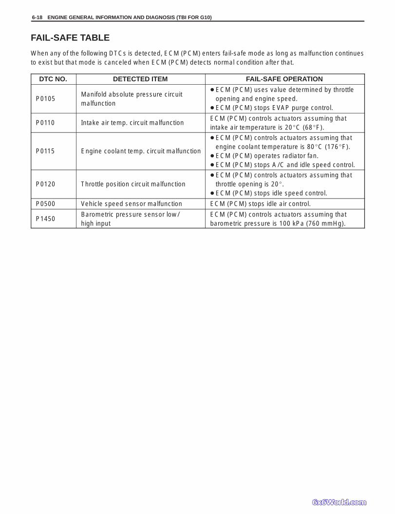
FAIL-SAFE TABLE
When any of the following DTCs is detected, ECM (PCM) enters fail-safe mode as long as malfunction continuesto exist but that mode is canceled when ECM (PCM) detects normal condition after that.
DTC NO. DETECTED ITEM FAIL-SAFE OPERATION
P0105Manifold absolute pressure circuitmalfunction
ECM (PCM) uses value determined by throttleopening and engine speed.
ECM (PCM) stops EVAP purge control.
P0110 Intake air temp. circuit malfunctionECM (PCM) controls actuators assuming thatintake air temperature is 20C (68F).
P0115 Engine coolant temp. circuit malfunction
ECM (PCM) controls actuators assuming thatengine coolant temperature is 80C (176F).
ECM (PCM) operates radiator fan. ECM (PCM) stops A/C and idle speed control.
P0120 Throttle position circuit malfunction ECM (PCM) controls actuators assuming that
throttle opening is 20. ECM (PCM) stops idle speed control.
P0500 Vehicle speed sensor malfunction ECM (PCM) stops idle air control.
P1450Barometric pressure sensor low/high input
ECM (PCM) controls actuators assuming thatbarometric pressure is 100 kPa (760 mmHg).

ENGINE GENERAL INFORMATION AND DIAGNOSIS (TBI FOR G10) 6-19
Operation
VISUAL INSPECTION
Visually check following parts and systems.
INSPECTION ITEM REFERRING SECTION
Engine oil – – – – – level, leakage Engine coolant – – – – – level, leakage Fuel – – – – – level, leakage A/T fluid – – – – – level, leakage Air cleaner element – – – – – dirt, clogging Battery – – – – – fluid level, corrosion of terminal Water pump belt – – – – – tension, damage Throttle cable – – – – – play, installation Vacuum hoses of air intake system – – – – – disconnection,
looseness, deterioration, bend Connectors of electric wire harness – – – – – disconnection, friction Fuses – – – – – burning Parts – – – – – installation, bolt – – – – – looseness Parts – – – – – deformation Other parts that can be checked visuallyAlso check following items at engine start, if possible Malfunction indicator lamp Charge warning lamp Engine oil pressure warning lamp Engine coolant temp. meter Fuel level meter Tachometer, if equipped Abnormal air being inhaled from air intake system Exhaust system – – – – – leakage of exhaust gas, noise Other parts that can be checked visually
Section 0BSection 0BSection 0BSection 0BSection 0B
Section 0BSection 6E1
Section 8
Section 6Section 6HSection 8 (section 6 for pressure check)Section 8Section 8
6-20 ENGINE GENERAL INFORMATION AND DIAGNOSIS (TBI FOR G10)
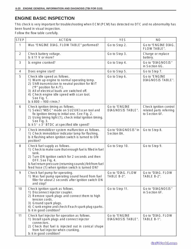
ENGINE BASIC INSPECTIONThis check is very important for troubleshooting when ECM (PCM) has detected no DTC and no abnormality hasbeen found in visual inspection.Follow the flow table carefully.
STEP ACTION YES NO
1 Was “ENGINE DIAG. FLOW TABLE” performed? Go to Step 2. Go to “ENGINE DIAG.FLOW TABLE”.
2 Check battery voltage.Is it 11 V or more?
Go to Step 3. Charge or replacebattery.
3 Is engine cranked? Go to Step 4. Go to “DIAGNOSIS”in Section 6G.
4 Does engine start? Go to Step 5. Go to Step 7.
5 Check idle speed as follows.1) Warm up engine to normal operating temp.2) Shift transmission to neutral position for M/T
(“P” position for A/T).3) All of electrical loads are switched off.4) Check engine idle speed with scan tool.
See Fig. 1.Is it 800 – 900 r /min.?
Go to Step 6. Go to “ENGINEDIAGNOSIS TABLE”.
6 Check ignition timing as follows.1) Select “MISC” mode on SUZUKI scan tool and
fix ignition timing to initial one. See Fig. 2.2) Using timing light (1), check initial ignition timing.
See Fig. 3.Is it 5 ± 3 BTDC at specified idle speed?
Go to “ENGINEDIAGNOSIS TABLE”.
Check ignition controlrelated parts referringto Section 6F.
7 Check immobilizer system malfunction as follows.1) Check immobilizer indicator lamp for flashing.Is it flashing when ignition switch is turned to ONposition?
Go to “DIAGNOSIS” inSection 8A.
Go to Step 8.
8 Check fuel supply as follows.1) Check to make sure that enough fuel is filled in fuel
tank.2) Turn ON ignition switch for 2 seconds and then
OFF. See Fig. 4.Is fuel return pressure (returning sounds) felt from fuelfeed hose (1) when ignition switch is turned ON?
Go to Step 10. Go to Step 9.
9 Check fuel pump for operating.1) Was fuel pump operating sound heard from fuel
filler for about 2 seconds after ignition switch ONand stop?
Go to “DIAG. FLOWTABLE B-3”.
Go to “DIAG. FLOWTABLE B-2”.
10 Check ignition spark as follows.1) Disconnect injector coupler.2) Remove spark plugs and connect them to high
tension cords.3) Ground spark plugs.4) Crank engine and check if each spark plug sparks.Is it in good condition?
Go to Step 11. Go to “DIAGNOSIS”in Section 6F.
11 Check fuel injector for operation as follows.1) Install spark plugs and connect injector
connectors.2) Check that fuel is injected out in conical shape
from fuel injector when cranking.Is it in good condition?
Go to “ENGINEDIAGNOSIS TABLE”.
Go to “DIAG. FLOWTABLE B-1”.

Select “DATALIST” mode
SELECT MENUF4: MISC TEST
ENGINE GENERAL INFORMATION AND DIAGNOSIS (TBI FOR G10) 6-21
Fig. 1 for Step 5 Fig. 2 for Step 6 Fig. 3 for Step 6
Fig. 4 for Step 8 Fig. 5 for Step 11

6-22 ENGINE GENERAL INFORMATION AND DIAGNOSIS (TBI FOR G10)
ENGINE DIAGNOSIS TABLE
Perform troubleshooting referring to following table when ECM (PCM) has detected no DTC and no abnormalityhas been found in visual inspection and engine basic inspection previously.
Condition Possible Cause Referring Item
Hard Starting(Engine cranks OK)
Ignition system out of order Faulty spark plug Leaky high-tension cord Loose connection or disconnection of high-
tension cords or lead wires Faulty ignition coilFuel system out of order Dirty or clogged fuel hose or pipe Malfunctioning fuel pump Air inhaling from intake manifold gasket or
throttle body gasket Fuel injector resistor malfunctionEngine and emission control system out oforder Faulty idle control system Faulty ECT sensor or MAP sensor
Faulty ECM (PCM)Low compression
Poor spark plug tightening or faulty gasket Compression leak from valve seat Sticky valve stem
Weak or damaged valve springs
Compression leak at cylinder head gasket
Sticking or damaged piston ring
Worn piston, ring or cylinder
Others Malfunctioning PCV valve
Spark plugs in Section 6FHigh-tension cords in Section 6FHigh-tension cords in Section 6F
Ignition coil in Section 6F
Diagnostic Flow Table B-3Diagnostic Flow Table B-3
Fuel injector resistor in Section 6E1
Diagnostic Flow Table P0505ECT sensor or MAP sensor inSection 6E1
Compression check in Section6ASpark plugs in Section 6FValves inspection in Section 6AValves inspection in Section 6A
Valve springs inspection inSection 6ACylinder head inspection inSection 6ACylinders, pistons and piston ringsinspection in Section 6ACylinders, pistons and piston ringsinspection in Section 6A
PCV system in Section 6E1
ENGINE GENERAL INFORMATION AND DIAGNOSIS (TBI FOR G10) 6-23
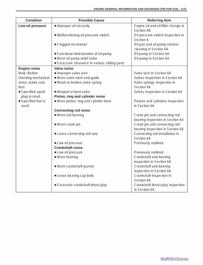
Condition Possible Cause Referring Item
Low oil pressure Improper oil viscosity
Malfunctioning oil pressure switch
Clogged oil strainer
Functional deterioration of oil pump Worn oil pump relief valve Excessive clearance in various sliding parts
Engine oil and oil filter change inSection 0BOil pressure switch inspection inSection 8Oil pan and oil pump strainercleaning in Section 6AOil pump in Section 6AOil pump in Section 6A
Engine noiseNote: Beforechecking mechanicalnoise, make surethat: Specified spark
plug in used. Specified fuel is
used.
Valve noise Improper valve lash Worn valve stem and guide Weak or broken valve spring
Warped or bent valvePiston, ring and cylinder noise Worn piston, ring and cylinder bore
Connecting rod noise Worn rod bearing
Worn crank pin
Loose connecting rod nuts
Low oil pressureCrankshaft noise Low oil pressure Worn bearing
Worn crankshaft journal
Loose bearing cap bolts
Excessive crankshaft thrust play
Valve lash in Section 6AValves inspection in Section 6AValve springs inspection inSection 6AValves inspection in Section 6A
Pistons and cylinders inspectionin Section 6A
Crank pin and connecting rodbearing inspection in Section 6ACrank pin and connecting rodbearing inspection in Section 6AConnecting rod installation inSection 6APreviously outlined
Previously outlinedCrankshaft and bearinginspection in Section 6ACrankshaft and bearinginspection in Section 6ACrankshaft inspection inSection 6ACrankshaft thrust play inspectionin Section 6A

6-24 ENGINE GENERAL INFORMATION AND DIAGNOSIS (TBI FOR G10)
Condition Possible Cause Referring Item
Overheating Inoperative thermostat Poor water pump performance Clogged or leaky radiator Improper engine oil grade
Clogged oil filter or oil strainer Poor oil pump performance Faulty radiator fan control system
Dragging brakes Slipping clutch Blown cylinder head gasket
Thermostat in Section 6BWater pump in Section 6BRadiator in Section 6BEngine oil and oil filter change inSection 0BOil pressure check in Section 6AOil pressure check in Section 6ARadiator fan control system inSection 6E1Trouble diagnosis in Section 5Trouble diagnosis in Section 7CCylinder head in Section 6A
Poor gasolinemileage
Ignition system out of order Leaks or loose connection of high-tension cord Faulty spark plug (improper gap, heavy deposits
and burned electrodes, etc.)Engine and emission control system out oforder High idle speed
Poor performance of TP sensor, ECT sensor orMAP sensor
Faulty fuel injector Faulty fuel injector resistor Faulty ECM (PCM)Low compressionOthers Poor valve seating Dragging brakes Slipping clutch Thermostat out of order Improper tire pressure
High-tension cords in Section 6FSpark plugs in Section 6F
Refer to item “Improper engineidle speed” previously outlinedTP sensor, ECT sensor or MAPsensor in Section 6E1Diagnostic Flow Table B-1Fuel injector resistor in Section 6E1
Previously outlined
Valves inspection in Section 6ATrouble diagnosis in Section 5Trouble diagnosis in Section 7CThermostat in Section 6BRefer to Section 3F
Excessive engineoil consumption
Oil leakage Blown cylinder head gasket Leaky camshaft oil sealsOil entering combustion chamber Sticky piston ring Worn piston and cylinder
Worn piston ring groove and ring Improper location of piston ring gap Worn or damaged valve stem seal
Worn valve stem
Cylinder head in Section 6ACamshaft in Section 6A
Piston cleaning in Section 6APistons and cylinders inspectionin Section 6APistons inspection in Section 6APistons assembly in Section 6AValves removal and installation inSection 6AValves inspection in Section 6A

ENGINE GENERAL INFORMATION AND DIAGNOSIS (TBI FOR G10) 6-25
Condition Possible Cause Referring Item
Engine hesitates(Momentary lack ofresponse asaccelerator isdepressed.Can occur at allvehicle speeds.Usually most severewhen first trying tomake vehicle move,as from a stop sign.)
Ignition system out of order Spark plug faulty or plug gap out of adjustment Leaky high-tension cordFuel system out of order Fuel pressure out of specificationEngine and emission control system out oforder Poor performance of TP sensor, ECT sensor or
MAP sensor Faulty fuel injector Faulty ECM (PCM)Engine overheatingLow compression
Spark plugs in Section 6FHigh-tension cords in Section 6F
Diagnostic Flow Table B-3Trouble diagnosis in Section 6
TP sensor, ECT sensor or MAPsensor in Section 6E1Diagnostic Flow Table B-1
Refer to “Overheating” sectionPreviously outlined
Surge(Engine powervariation understeady throttle orcruise.Feels like vehiclespeeds up and downwith no change inaccelerator pedal.)
Ignition system out of order Leaky or loosely connected high-tension cord Faulty spark plug (excess carbon deposits,
improper gap, and burned electrodes, etc.)Fuel system out of order Variable fuel pressure Kinky or damaged fuel hose and lines Faulty fuel pump (clogged fuel filter)Engine and emission control system out oforder Poor performance of MAP sensor Faulty fuel injector Faulty ECM (PCM)
High-tension cords in Section 6FSpark plugs in Section 6F
Diagnostic Flow Table B-3
MAP sensor in Section 6E1Diagnostic Flow Table B-1
Excessivedetonation(Engine makescontinuouslysharp metallicknocks that changewith throttle opening.Sounds like pop cornpopping.)
Engine overheatingIgnition system out of order Faulty spark plug Loose connection of high-tension cordFuel system out of order Clogged fuel filter (faulty fuel pump) or fuel lines Air inhaling from intake manifold or throttle body
gasketEngine and emission control system out oforder Poor performance of ECT sensor or MAP sensor
Faulty fuel injector Faulty ECM (PCM) Excessive combustion chamber deposits
Refer to “Overheating” section
Spark plugs in Section 6FHigh-tension cords in Section 6F
Diagnostic Flow Table B-1 or B-2
Trouble diagnosis in Section 6
ECT sensor or MAP sensor inSection 6E1Diagnostic Flow Table B-1
Piston and cylinder head cleaningin Section 6A

6-26 ENGINE GENERAL INFORMATION AND DIAGNOSIS (TBI FOR G10)
Condition Possible Cause Referring Item
Engine has nopower
Ignition system out of order Faulty spark plug Faulty ignition coil with ignitor Leaks, loose connection or disconnection of
high-tension cordEngine overheatingFuel system out of order Clogged fuel hose or pipe
Malfunctioning fuel pump Air inhaling from intake manifold gasket or
throttle body gasketEngine and emission control system out oforder Maladjusted accelerator cable play
Poor performance of TP sensor, ECT sensor orMAP sensor
Faulty fuel injector Faulty ECM (PCM)Low compressionOthers Dragging brakes Slipping clutch
Spark plugs in Section 6FIgnition coil in Section 6FHigh-tension cords in Section 6F
Refer to “Overheating” section
Diagnostic Flow Table B-3 inSection 6Diagnostic Flow Table B-2
Accelerator cable play in Section6E1TP sensor, ECT sensor or MAPsensor in Section 6E1Diagnostic Flow Table B-1
Previously outlined
Trouble diagnosis in Section 5Trouble diagnosis in Section 7C
ENGINE GENERAL INFORMATION AND DIAGNOSIS (TBI FOR G10) 6-27
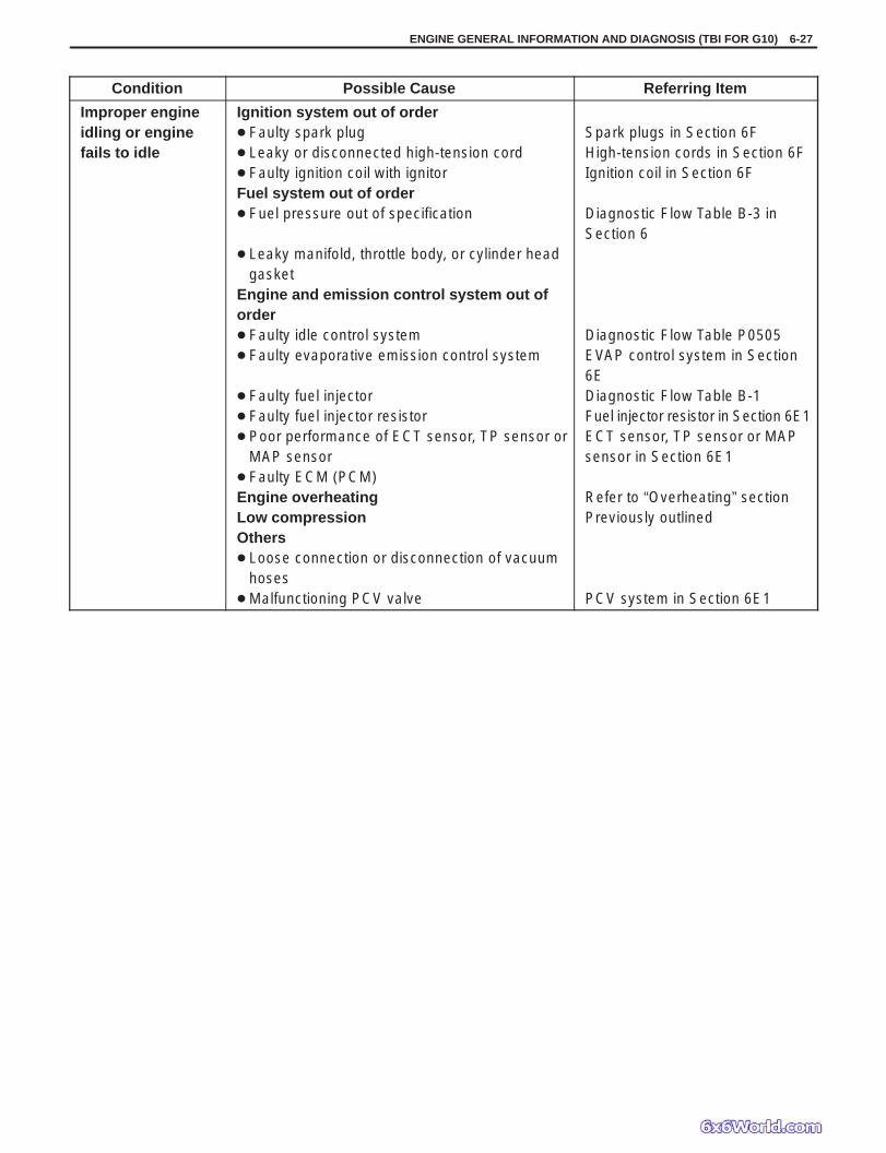
Condition Possible Cause Referring Item
Improper engineidling or enginefails to idle
Ignition system out of order Faulty spark plug Leaky or disconnected high-tension cord Faulty ignition coil with ignitorFuel system out of order Fuel pressure out of specification
Leaky manifold, throttle body, or cylinder headgasket
Engine and emission control system out oforder Faulty idle control system Faulty evaporative emission control system
Faulty fuel injector Faulty fuel injector resistor Poor performance of ECT sensor, TP sensor or
MAP sensor Faulty ECM (PCM)Engine overheatingLow compressionOthers Loose connection or disconnection of vacuum
hoses Malfunctioning PCV valve
Spark plugs in Section 6FHigh-tension cords in Section 6FIgnition coil in Section 6F
Diagnostic Flow Table B-3 inSection 6
Diagnostic Flow Table P0505EVAP control system in Section6EDiagnostic Flow Table B-1Fuel injector resistor in Section 6E1ECT sensor, TP sensor or MAPsensor in Section 6E1
Refer to “Overheating” sectionPreviously outlined
PCV system in Section 6E1
6-28 ENGINE GENERAL INFORMATION AND DIAGNOSIS (TBI FOR G10)
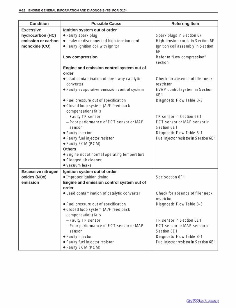
Condition Possible Cause Referring Item
Excessivehydrocarbon (HC)emission or carbonmonoxide (CO)
Ignition system out of order Faulty spark plug Leaky or disconnected high-tension cord Faulty ignition coil with ignitor
Low compression
Engine and emission control system out oforder Lead contamination of three way catalytic
converter Faulty evaporative emission control system
Fuel pressure out of specification Closed loop system (A/F feed back
compensation) fails– Faulty TP sensor– Poor performance of ECT sensor or MAP
sensor Faulty injector Faulty fuel injector resistor Faulty ECM (PCM)Others Engine not at normal operating temperature Clogged air cleaner Vacuum leaks
Spark plugs in Section 6FHigh-tension cords in Section 6FIgnition coil assembly in Section6FRefer to “Low compression”section
Check for absence of filler neckrestrictorEVAP control system in Section6E1Diagnostic Flow Table B-3
TP sensor in Section 6E1ECT sensor or MAP sensor inSection 6E1Diagnostic Flow Table B-1Fuel injector resistor in Section 6E1
Excessive nitrogenoxides (NOx)emission
Ignition system out of order Improper ignition timingEngine and emission control system out oforder Lead contamination of catalytic converter
Fuel pressure out of specification Closed loop system (A/F feed back
compensation) fails– Faulty TP sensor– Poor performance of ECT sensor or MAP
sensor Faulty injector Faulty fuel injector resistor Faulty ECM (PCM)
See section 6F1
Check for absence of filler neckrestrictor.Diagnostic Flow Table B-3
TP sensor in Section 6E1ECT sensor or MAP sensor inSection 6E1Diagnostic Flow Table B-1Fuel injector resistor in Section 6E1
ENGINE GENERAL INFORMATION AND DIAGNOSIS (TBI FOR G10) 6-29
Ambient temp.
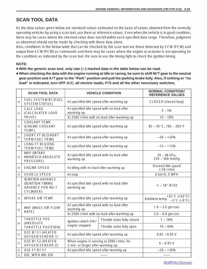
SCAN TOOL DATA
As the data values given below are standard values estimated on the basis of values obtained from the normallyoperating vehicles by using a scan tool, use them as reference values. Even when the vehicle is in good condition,there may be cases where the checked value does not fall within each specified data range. Therefore, judgmentas abnormal should not be made by checking with these data alone.Also, conditions in the below table that can be checked by the scan tool are those detected by ECM (PCM) andoutput from ECM (PCM) as commands and there may be cases where the engine or actuator is not operating (inthe condition) as indicated by the scan tool. Be sure to use the timing light to check the ignition timing.
NOTE: With the generic scan tool, only star () marked data in the table below can be read. When checking the data with the engine running at idle or racing, be sure to shift M/T gear to the neutral
gear position and A/T gear to the “Park” position and pull the parking brake fully. Also, if nothing or “noload” is indicated, turn OFF A/C, all electric loads, P/S and all the other necessary switches.
SCAN TOOL DATA VEHICLE CONDITION NORMAL CONDITION/REFERENCE VALUES
FUEL SYSTEM B1 (FUELSYSTEM STATUS)
At specified idle speed after warming up CLOSED (closed loop)
CALC LOAD(CALCULATED LOAD
At specified idle speed with no load afterwarming up
3 – 5%(VALUE) At 2500 r /min with no load after warming up 10 – 18%
COOLANT TEMP.(ENGINE COOLANTTEMP.)
At specified idle speed after warming up 85 – 95C, 185 – 203F
SHORT FT BI (SHORTTERM FUEL TRIM)
At specified idle speed after warming up –20 – +20%
LONG FT BI (LONGTERM FUEL TRIM)
At specified idle speed after warming up –15 – +15%
MAP (INTAKEMANIFOLD ABSOLUTEPRESSURE)
At specified idle speed with no load afterwarming up
29 – 48 kPa,220 – 360 mmHg
ENGINE SPEED At idling with no load after warming up Desired idle speed± 50 r /min
VEHICLE SPEED At stop 0 km/h, 0 MPH
IGNITION ADVANCE(IGNITION TIMINGADVANCE FOR NO.1CYLINDER)
At specified idle speed with no load afterwarming up
–1 – 18 BTDC
INTAKE AIR TEMP. At specified idle speed after warming up +35C (+63F)–5C (–9F)
MAF (MASS AIR FLOWRATE)
At specified idle speed with no load afterwarming up
1.0 – 3.0 gm/secRATE)
At 2500 r /min with no load after warming up 3.0 – 6.0 gm/sec
THROTTLE POS(ABSOLUTE Ignition switch ON/ Throttle valve fully closed 7 – 18%
(ABSOLUTETHROTTLE POSITION)
gengine stopped Throttle valve fully open 70 – 90%
O2S B1 S1 (HEATEDOXYGEN SENSOR-1)
At specified idle speed after warming up 0.05 – 0.95 V
O2S B1 S2 (HEATEDOXYGEN SENSOR-2)
When engine is running at 2000 r /min. for 3 min. or longer after warming up.
0 – 0.95 V
O2S FT B1 S1 At specified idle speed after warning up –20 – +20%
DIS. WITH MIL ON —— ——

6-30 ENGINE GENERAL INFORMATION AND DIAGNOSIS (TBI FOR G10)
SCAN TOOL DATA CONDITION NORMAL CONDITION/REFERENCE VALUES
DESIRED IDLE At idling with no load after warming up, M/T850 r/min(DESIRED IDLE SPEED)
g g ,at neutral, A/T at “P” range 850 r /min
TP SENSOR VOLT(THROTTLE POSITION Ignition switch
ON/engineThrottle valve fully closed More than 0.2 V
(SENSOR OUTPUTVOLTAGE)
ON/enginestopped Throttle valve fully open Less than 4.8 V
INJ PULSE WIDTH(FUEL INJECTION
At specified idle speed with no load afterwarming up 0.8 – 2.3 msec.
(PULSE WIDTH) At 2500 r /min with no load after warming up 0.8 – 2.3 msec.
IAC FLOW DUTY (IDLEAIR CONTROL FLOWDUTY)
At idling with no load after warming up 20 – 40%
TOTAL FUEL TRIM At specified idle speed after warming up –35 – +35%
BATTERY VOLTAGE Ignition switch ON/engine stop 10 – 14 V
CANIST PRG DUTY(EVAP CANISTERPURGE FLOW DUTY)
At specified idle speed after warming up 0 – 100%
CLOSED THROT POS(CLOSED THROTTLE
Throttle valve at idle position ON(CLOSED THROTTLEPOSITION) Throttle valve opens larger than idle position OFF
FUEL CUTWhen engine is at fuel cut condition ON
FUEL CUTOther than fuel cut condition OFF
RAD FAN(RADIATOR FAN Ignition switch
ON
Engine coolant temp.:Lower than 92.5C
(199F)OFF
(CONTROL RELAY) ON
Engine coolant temp.:97.5C (208F) or higher ON
ELECTRIC LOAD
Ignition switch ON/Headlight, small light,heater fan and rear window defogger allturned OFF
OFF
ELECTRIC LOADIgnition switch ON/Headlight, small light,heater fan or rear window defogger turnedON
ON
A/C SWITCH
Engine running after warming up, A/C notoperating OFF
A/C SWITCHEngine running after warming up, A/Coperating ON
PSP SWITCHEngine running at idle speed and steering wheelat straight-ahead position. OFF
(if equipped). Engine running at idle speed and steering wheelturned to the right or left as far as it stops. ON
FUEL TANK LEVEL –––––––––––– 0 – 100%
BAROMETRIC PRESS –––––––––––– Display the barometric pressure
FUEL PUMPWithin 3 seconds after ignition switch ON orengine running ON
Engine stop at ignition switch ON. OFF

ENGINE GENERAL INFORMATION AND DIAGNOSIS (TBI FOR G10) 6-31
SCAN TOOL DATA CONDITION NORMAL CONDITION/REFERENCE VALUES
VSS (for 4-A/T)(Vehicle Speed Sensor) At stop. 0 km/h 0 MPH
SHIFT SOL1CON (Command Signal)MON (Monitor Signal)
Ignition switch ON, selector lever is shifted at P,R or N range OFF
( g )SHIFT SOL2CON (Command Signal)MON (Monitor Signal)
Ignition switch ON, selector lever is shifted at Drange and vehicle stops ON
THROT POS LEVEL(THROTTLE POSITIONLEVER FOR A/T)
“0” (about idle position), “1”, “2”, “3”, “4”, “5”, “6” or “7” (about full open) appearsaccording to throttle valve opening.
TRANS. RANGE(TRANSMISSIONRANGE SENSOR)
“P”, “R”, “N”, “D”, “2” or “L” appears according tho selector lever position.
GEAR POSITIONSelect lever at D, 2 or L range 1
GEAR POSITIONSelect lever at P, N or R range –

6-32 ENGINE GENERAL INFORMATION AND DIAGNOSIS (TBI FOR G10)
SCAN TOOL DATA DEFINITIONSFUEL SYSTEM (FUEL SYSTEM STATUS)Air/ fuel ratio feedback loop status displayed as eitheropen or closed loop. Open indicates that ECM (PCM)ignores feedback from the exhaust oxygen sensor.Closed indicates final injection duration is correctedfor oxygen sensor feedback.
CALC LOAD (CALCULATED LOAD VALUE, %)Engine load displayed as a percentage of maximumpossible load. Value is calculated mathematically us-ing the formula: actual (current) intake air volume maximum possible intake air volume x 100%.
COOLANT TEMP.(ENGINE COOLANT TEMPERATURE, C, F)It is detected by engine coolant temp. sensor
SHORT FT B1 (SHORT TERM FUEL TRIM, %)Short term fuel trim value represents short termcorrections to the air / fuel mixture computation. A val-ue of 0 indicates no correction, a value greater than0 means an enrichment correction, and a value lessthan 0 implies an enleanment correction.
LONG FT B1 (LONG TERM FUEL TRIM, %)Long term fuel trim Value represents long term correc-tions to the air / fuel mixture computation. A value of 0indicates no correction, a value greater than 0 meansan enrichment correction, and a value less than 0 im-plies an enleanment correction.
MAP (INTAKE MANIFOLD ABSOLUTEPRESSURE, kPa, inHg)It is detected by manifold absolute pressure sensor andused (among other things) to compute engine load.
ENGINE SPEED (rpm)It is computed by reference pulses from crankshaftposition sensor.
VEHICLE SPEED (km/h, MPH)It is computed based on pulse signals from vehiclespeed sensor.
IGNITION ADVANCE(IGNITION TIMING ADVANCE FOR NO.1CYLINDER, )Ignition timing of NO.1 cylinder is commanded byECM (PCM). The actual ignition timing should bechecked by using the timing light.
INTAKE AIR TEMP. (C, F)It is detected by intake air temp. sensor and used todetermine the amount of air passing into the intakemanifold as air density varies with temperature.
MAF (MASS AIR FLOW RATE, gm/s, lb/min)It represents total mass of air entering intake manifoldwhich is computed based on signals from MAP sen-sor, IAT sensor, TP sensor, etc.
THROTTLE POS(ABSOLUTE THROTTLE POSITION, %)When throttle position sensor is fully closed position,throttle opening is indicated as 0% and 100% full openposition.
OXYGEN SENSOR B1 S1(HEATED OXYGEN SENSOR-1, V)It indicates output voltage of HO2S-1 installed on ex-haust manifold (pre-catalyst).
OXYGEN SENSOR B1 S2(HEATED OXYGEN SENSOR-2, V)It indicates output voltage of HO2S-2 installed on ex-haust pipe (post-catalyst). It is used to detect catalystdeterioration.
DESIRED IDLE (DESIRED IDLE SPEED, rpm)The Desired Idle Speed is an ECM (PCM) internal pa-rameter which indicates the ECM (PCM) requestedidle. If the engine is not running, this number is not valid.
TP SENSOR VOLT (THROTTLE POSITIONSENSOR OUTPUT VOLTAGE, V)The Throttle Position Sensor reading provides throttlevalve opening information in the form of voltage.
INJ PULSE WIDTH(FUEL INJECTION PULSE WIDTH, msec.)This parameter indicates time of the injector drive(valve opening) pulse which is output from ECM(PCM) (but injector drive time of NO.1 cylinder formultiport fuel injection).
IAC FLOW DUTY (IDLE AIR (SPEED) CONTROLDUTY, %)This parameter indicates opening of the throttle valvein terms of percentage to opening controllable by theISC actuator.
TOTAL FUEL TRIM (%)The value of Total Fuel Trim is obtained by putting val-ues of short Term Fuel Trim and Long Term Fuel Trimtogether. This value indicates how much correction isnecessary to keep the air / fuel mixture stoichiomet-rical.
BATTERY VOLTAGE (V)This parameter indicates battery positive voltage in-putted from main relay to ECM (PCM).
ENGINE GENERAL INFORMATION AND DIAGNOSIS (TBI FOR G10) 6-33
CANIST PURGE DUTY (EVAP CANISTERPURGE FLOW DUTY, %)This parameter indicates valve ON (valve open) timerate within a certain set cycle of EVAP purge solenoidvalve which controls the amount of EVAP purge.0% means that the purge valve is completely closedwhile 100% is a fully open valve.
CLOSED THROTTLE POSITION (ON/OFF)This parameter will read ON when throttle valve is ful-ly closed, or OFF when the throttle is not fully closed.
FUEL CUT (ON/OFF)ON : Fuel being cut (output signal to injector is
stopped)OFF : Fuel not being cut
RAD FAN(RADIATOR FAN CONTROL RELAY, ON/OFF)ON : Command for radiator fan control relay opera-
tion being output.OFF : Command for relay operation not being out-
put.
ELECTRIC LOAD (ON/OFF)ON : Headlight, small light, heater fan or rear win-
dow defogger ON signal inputted.OFF : Above electric loads all turned OFF.
A/C SWITCH (ON/OFF)ON : Command for A/C operation being output
from ECM (PCM) to A/C amplifier.OFF : Command for A/C operation not being output.
FUEL TANK LEVEL (%)This parameter indicates approximate fuel level in thefuel tank. As the detectable range of the fuel level sen-sor is set as 0 to 100%, however, with some modelswhose fuel tank capacity is smaller, the indicated fuellevel may be only 70% even when the fuel tank is full.
PSP SWITCH (ON/OFF)ON : PSP switch detects P/S operation (high PS
pressure).OFF : PSP switch not detects P/S operation.
BAROMETRIC PRESS (kPa, inHg)This parameter represents a measurement of baro-metric air pressure and is used for altitude correctionof the fuel injection quantity and ISC actuator control.
FUEL PUMP (ON/OFF)ON is displayed when the ECM (or PCM) activates thefuel pump via the fuel pump relay switch.
VSS (A/T) (km/h, MPH)If is computed by using pulse signals from vehicle(output) speed sensor on automatic transmission.
TRANS RANGE (TRANSMISSION RANGESENSOR, P, R, N, D, 2 OR L)It is indicated transmission range detected by trans-mission range sensor.
SHIFT SOL 1-CON (SHIFT SOLENOID-1,ON/OFF)ON : ON command being output to shift solenoid-1OFF : ON command not being output.
SHIFT SOL 2-CON (SHIFT SOLENOID-2,ON/OFF)ON : ON command being output to shift solenoid-2OFF : ON command not being output.
SHIFT SOL 1-MON (SHIFT SOLENOID-1,ON/OFF)The monitor result of the shift solenoid-1 circuit is dis-played.ON : Electricity being passed to shift solenoid-1 or
circuit open.OFF : Electricity not being passed or circuit short.
SHIFT SOL 2-MON (SHIFT SOLENOID-2,ON/OFF)The monitor result of the shift solenoid-2 circuit is dis-played.ON : Electricity being passed to shift solenoid-2 or
circuit open.OFF : Electricity not being passed or circuit short.
THROT POS LEVEL (THROTTLE POSITIONLEVEL FOR A/T, “0”, “1”, “2”, “3”, “4”, “5”, “6”or “7”)This parameter indicates which level (zone) thethrottle valve opening is in. The throttle opening is di-vided into 8 levels (zones) from “0” (about idle posi-tion) to “7” (about full open) and signals are assignedto each opening level (zone). ECM (PCM) control theautomatic gear change of the automatic transmissionby using these signals according to the signal fromthe TP sensor.
GEAR POSITIONThis parameter indicates the A/T gear position whichis computed on signals from the Transmission RangeSwitch, VSS, TP Sensor, and so forth.

6-34 ENGINE GENERAL INFORMATION AND DIAGNOSIS (TBI FOR G10)
1. ECM (PCM)2. ECM (PCM) couplers
(Viewed from harness side)
1. ECM (PCM)2. Couplers3. Body ground4. Service wire
16
C03C02 C01
12
12345678910111234567812345678910
111213
1213141516171819202122910111213141514151617181920212223242526
INSPECTION OF ECM (PCM) AND ITSCIRCUITS
ECM (PCM) and its circuits can be checked at ECM (PCM) wiringcouplers by measuring voltage and resistance.
CAUTION:ECM (PCM) cannot be checked by itself. It is strictly prohib-ited to connect voltmeter or ohmmeter to ECM (PCM) withcoupler disconnected from it.
Voltage Check1) Remove ECM (PCM) (1) from body referring to Section 6E.2) Check voltage at each terminal of couplers (2) connected.
NOTE:As each terminal voltage is affected by the battery voltage,confirm that it is 11 V or more when ignition switch is ON.

ENGINE GENERAL INFORMATION AND DIAGNOSIS (TBI FOR G10) 6-35
CO
NN
EC
TO
R “
C02
”TER-
MINALWIRE
COLORCIRCUIT
STANDARDVOLTAGE
CONDITION
1 B ECM (PCM) ground – –
2 W/Bl Power source 10 – 14 V Ignition switch ON
3 — Blank — —
4 — Blank — —
5 — Blank — —
6 — Blank — —
7 R/G EVAP canister purge valve 10 – 14 V Ignition switch ON
8 G/Or Shift solenoid B (A/T)
0 VIgnition switch ON, selector lever at “P”range
8 G/Or Shift solenoid-B (A/T)10 – 14 V
Ignition switch ON, selector lever at “D”range
9 G/W Shift solenoid A (A/T)
0 VIgnition switch ON, selector lever at “P”range
9 G/W Shift solenoid-A (A/T)10 – 14 V
Ignition switch ON, selector lever at “D”range
10 Or Igniter (IGT) — —
11 Gr/Y ISC actuator — —
12 Y/B Fuel injector 10 – 14 V Ignition switch ON
13 B/Bl Ground for injector — —
14 W Power source for back-up 10 – 14 V Ignition switch ON and OFF
15 W/Bl Power source 10 – 14 V Ignition switch ON
16 Gr/B ISC actuator relay 0.3 – 1.0 V Ignition switch ON
17 V/Y Malfunction indicator lamp0.2 – 2.0 V Ignition switch ON
17 V/Y Malfunction indicator lamp10 – 14 V When engine running
18 V/G Immobilizer indicator lamp0.2 – 2.0 V Ignition switch ON
18 V/G Immobilizer indicator lamp10 – 14 V When engine running at idle
19 Lg/B Heater of H02S-2 10 – 14 V Ignition switch ON
20 Bl Radiator fan control relay
10 – 14 VIgnition switch ON, Engine coolanttemp: Below 91.5C (197F)
20 Bl Radiator fan control relay0.3 – 1.0 V
Ignition switch ON, Engine coolanttemp: 96.0C (205F) or higher
21 P/W Fuel pump relay0.3 – 1.3 V For 2 seconds after ignition switch ON
21 P/W Fuel pump relay10 – 14 V After the above time
22 Bl/B Main relay 0.4 – 1.5 V Ignition switch ON
23 – Blank — —
24 Gr/R ISC actuator — —
25 Y/R EFE heater relay 10 – 14 V Ignition switch ON
26 B/R Ground for injector — —

6-36 ENGINE GENERAL INFORMATION AND DIAGNOSIS (TBI FOR G10)
CO
NN
EC
TO
R “
C01
”TER-
MINALWIRE
COLORCIRCUIT
STANDARDVOLTAGE
CONDITION
1 Lg Power source for sensor 4.75 – 5.25 V Ignition switch ON
2 Or Camshaft position sensor (+) — —
3 W/BCrankshaft position sensor(+)
— —
4 Gr/GClosed throttle position switch
0 – 1 VIgnition switch ON, ISC actuatorplunger is in contact with throttle leverscrew
4 Gr/G(In ISC actuator)
4 – 6 VIgnition switch ONPlunger is apart from throttle leverscrew
5 Lg/RManifold absolute pressuresensor
3.3 – 4.0 VIgnition switch ONBarometric pressure: 100 kPa,760 mmHg
6 Lg/W Throttle position sensor0.2 – 1.0 V
Ignition switch ON, when clearancebetween throttle lever and throttle stopscrew is less than 0.35 mm (0.014 in.)
2.8 – 4.8 VIgnition switch ONThrottle valve at full open position
7 Gr/W Engine coolant temp. sensor 0.55 – 0.95 VIgnition switch ONEngine coolant temp.: 80C (176F)
8 P/B Heater of H02S-1 10 – 14 V Ignition switch ON
9 G Ground for sensors — —
10 W Camshaft position sensor (–) — —
11 W/RCrankshaft position sensor(+)
— —
12 W/B EFE heater monitor0 – 1 V Heater relay OFF
12 W/B EFE heater monitor10 – 14 V Heater relay ON
13 R Heated oxygen sensor-1 Refer to DTC flow chart
14 Gr Intake air temp. sensor 2.0 – 2.7 VIgnition switch ONSensor ambient temp.(Intake air temp): 20C (68F)
10 – 14 V Ignition switch ON
15 Bl/WPower steering pressureswitch (If equipped) 0 – 1 V
With engine running at idle speed,turning steering wheel to the right or leftas far as it stops, repeating it a fewtimes
16 B/YEngine start switch 6 – 12 V While engine cranking
16 B/Yg
(Engine start signal) 0 – 1 V Other than above

ENGINE GENERAL INFORMATION AND DIAGNOSIS (TBI FOR G10) 6-37
CO
NN
EC
TO
R “
C03
”TER-
MINALWIRE
COLORCIRCUIT STANDARD
VOLTAGECONDITION
1 V/WData link connector(SUZUKI serial data line)
4 – 6 V Ignition switch ON
Bl Vehicle speed sensor (+) (A/T) 0.4 – 0.8 V Ignition switch ON
2Y/G Vehicle speed sensor (M/T)
Indicatordeflectionrepeated0 V and 4 – 6 V
Ignition switch ONFront left tire turned slowly with frontright tire locked
3 G Transmis-sion range
“2” rangeIgnition switch ON, Selector lever at “2”range
4 Or/Ysion rangesensor(switch)
“N” range 10 – 14 V Ignition switch ON, Selector lever at “N”range
5 Or/B
(switch)(A/T only). “P” range
Ignition switch ON, Selector lever at “P”range
6 — Blank – —
7 — Blank – —
8 R Heated oxygen sensor-2 Refer to DTC flow chart
9 — — — —
0 1 5 V Ignition switch ON fuel tank fully filled10 Y/R Fuel level sensor (gauge)
0 – 1.5 V Ignition switch ON, fuel tank fully filled10 Y/R Fuel level sensor (gauge)
3 5 5 V Ignition switch ON fuel tank emptied3 – 5.5 V Ignition switch ON, fuel tank emptied
11 — Blank — —
12 R/GData link connector(OBD serial data line)
10 – 14 V Ignition switch ON
13 P Vehicle speed sensor (–) (A/T) 0.4 – 0.8 V Ignition switch ON
14 G/Bl Transmis-sion range
“L” rangeSelector lever at “L”range
15 G/Rsion rangesensor(switch)
“D” range 10 – 14 VIgnitionswitch ON
Selector lever at “D”range
16 R
(switch)(A/T) “R” range
Selector lever at “R”range
17 Lg/RA/C ON (output) signal for A/Ccontroller (if equipped)
0 – 1 VWhile engine running and A/C notoperatingg
controller (if equipped)10 – 14 V While engine running and A/C operating
18 Br/Y Electric load signal
0 –1 VIgnition switch ONHeadlight, small light, heater fan andrear window defogger turned OFF
18 Br/Y Electric load signal
10 – 14 VIgnition switch ONHeadlight, small light, heater fan andrear window defogger turned ON
19 Bl/RA/C (input) signal for A/Camplifier
10 – 14 VWhile engine running and A/C notoperating
amplifier0 – 0.6 V While engine running and A/C operating
20 B/W Ignition switch 10 – 14 V Ignition switch ON
21 — Blank — —
22 — Blank — —

6-38 ENGINE GENERAL INFORMATION AND DIAGNOSIS (TBI FOR G10)
1
2
1. ECM (PCM)coupler disconnected
2. Ohmmeter
RESISTANCE CHECK1) Disconnect ECM (PCM) couplers from ECM (PCM) with ignition
switch OFF.
CAUTION:Never touch terminals of ECM (PCM) itself or connectvoltmeter or ohmmeter.
2) Check resistance between each terminal of couplers discon-nected.
CAUTION: Be sure to connect ohmmeter probe from wire harness
side of coupler. Be sure to turn OFF ignition switch for this check. Resistance in table below represents that when parts
temperature is 20C (68F).
TERMINALS CIRCUIT STANDARD RESISTANCE
C01-8 to C03-20 H02S-1 heater 11.7 – 14.3 ΩC02-19 to C03-20 H02S-2 heater 11.7 – 14.3 Ω
C02-12 to C02-2/15 Fuel injector 2.4 – 3.6 ΩC02-7 to C02-2/15 EVAP canister purge valve 30 – 34 ΩC02-21 to C03-20 Fuel pump relay 100 – 120 Ω
C02-16 to C02-2/15 ISC actuator relay 100 – 120 ΩC02-25 to C02-2/15 EFE heater relay 100 – 120 Ω
C02-8 to Body ground Shift solenoid-B 8 – 20 ΩC02-9 to Body ground Shift solenoid-A 8 – 20 ΩC02-20 to C02-2/15 Radiator fan control relay 100 – 120 ΩC02-22 to C02-14 Main relay 100 – 120 Ω
C02-1 to Body ground Ground Continuity
C02-13 to Body ground Ground Continuity
C02-26 to Body ground Ground Continuity
ENGINE GENERAL INFORMATION AND DIAGNOSIS (TBI FOR G10) 6-39
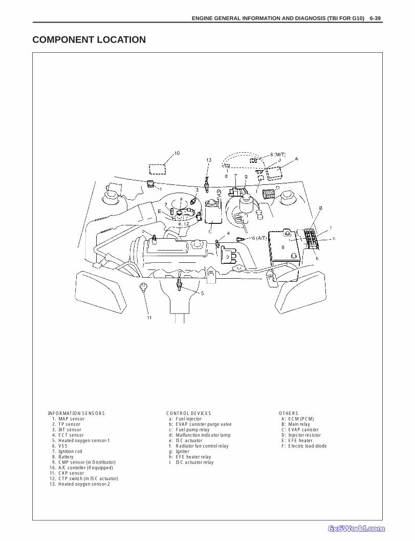
INFORMATION SENSORS-1. MAP sensor-2. TP sensor-3. IAT sensor-4. ECT sensor-5. Heated oxygen sensor-1-6. VSS-7. Ignition coil-8. Battery-9. CMP sensor (in Distributor)
-10. A/C contoller (if equipped)-11. CKP sensor-12. CTP switch (in ISC actuator)-13. Heated oxygen sensor-2
OTHERSA: ECM (PCM)B: Main relayC: EVAP canisterD: Injector resistorE: EFE heaterF: Electric load diode
CONTROL DEVICESa: Fuel injectorb: EVAP canister purge valvec: Fuel pump relayd: Malfunction indicator lampe: ISC actuatorf: Radiator fan control relayg: Igniterh: EFE heater relayi: ISC actuator relay
COMPONENT LOCATION
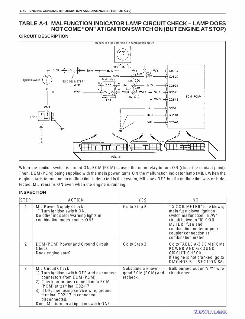
6-40 ENGINE GENERAL INFORMATION AND DIAGNOSIS (TBI FOR G10)
“IG COIL METER”Main relayIgnition switch
In fuse
Malfunction indicator lamp in combination meter
TABLE A-1 MALFUNCTION INDICATOR LAMP CIRCUIT CHECK – LAMP DOESNOT COME “ON” AT IGNITION SWITCH ON (BUT ENGINE AT STOP)
CIRCUIT DESCRIPTION
When the ignition switch is turned ON, ECM (PCM) causes the main relay to turn ON (close the contact point).Then, ECM (PCM) being supplied with the main power, turns ON the malfunction indicator lamp (MIL). When theengine starts to run and no malfunction is detected in the system, MIL goes OFF but if a malfunction was or is de-tected, MIL remains ON even when the engine is running.
INSPECTION
STEP ACTION YES NO
1 MIL Power Supply Check1) Turn ignition switch ON.Do other indicator/warning lights incombination meter comes ON?
Go to Step 2. “IG COIL METER” fuse blown,main fuse blown, ignitionswitch malfunction, “B/W”circuit between “IG COILMETER” fuse andcombination meter or poorcoupler connection atcombination meter.
2 ECM (PCM) Power and Ground CircuitCheckDoes engine start?
Go to Step 3. Go to TABLE A-3 ECM (PCM)POWER AND GROUNDCIRCUIT CHECK.If engine is not cranked, go toDIAGNOSIS in SECTION 8A.
3 MIL Circuit Check1) Turn ignition switch OFF and disconnect
connectors from ECM (PCM).2) Check for proper connection to ECM
(PCM) at terminal C02-17.3) If OK, then using service wire, ground
terminal C02-17 in connectordisconnected.
Does MIL turn on at ignition switch ON?
Substitute a known-good ECM (PCM) andrecheck.
Bulb burned out or “V/Y” wirecircuit open.
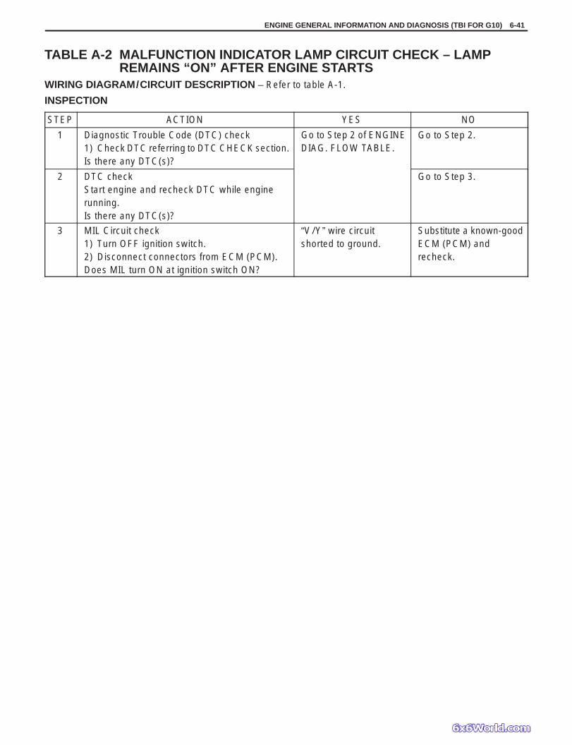
ENGINE GENERAL INFORMATION AND DIAGNOSIS (TBI FOR G10) 6-41
TABLE A-2 MALFUNCTION INDICATOR LAMP CIRCUIT CHECK – LAMPREMAINS “ON” AFTER ENGINE STARTS
WIRING DIAGRAM/CIRCUIT DESCRIPTION – Refer to table A-1.
INSPECTION
STEP ACTION YES NO
1 Diagnostic Trouble Code (DTC) check1) Check DTC referring to DTC CHECK section.Is there any DTC(s)?
Go to Step 2 of ENGINEDIAG. FLOW TABLE.
Go to Step 2.
2 DTC checkStart engine and recheck DTC while enginerunning.Is there any DTC(s)?
Go to Step 3.
3 MIL Circuit check1) Turn OFF ignition switch.2) Disconnect connectors from ECM (PCM).Does MIL turn ON at ignition switch ON?
“V/Y” wire circuitshorted to ground.
Substitute a known-goodECM (PCM) andrecheck.
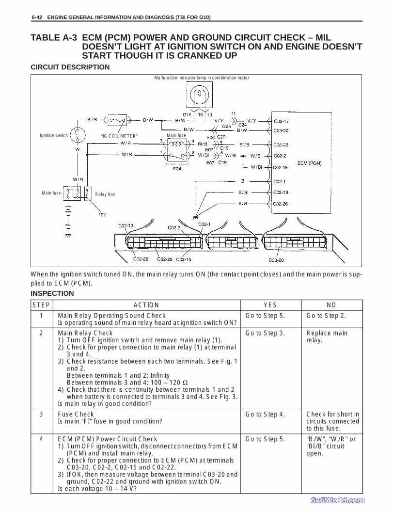
Main fuseIgnition switch
Main fuse
Malfunction indicator lamp in combination meter
Relay box
“IG COIL METER”
6-42 ENGINE GENERAL INFORMATION AND DIAGNOSIS (TBI FOR G10)
TABLE A-3 ECM (PCM) POWER AND GROUND CIRCUIT CHECK – MILDOESN’T LIGHT AT IGNITION SWITCH ON AND ENGINE DOESN’TSTART THOUGH IT IS CRANKED UP
CIRCUIT DESCRIPTION
When the ignition switch tuned ON, the main relay turns ON (the contact point closes) and the main power is sup-plied to ECM (PCM).
INSPECTION
STEP ACTION YES NO
1 Main Relay Operating Sound CheckIs operating sound of main relay heard at ignition switch ON?
Go to Step 5. Go to Step 2.
2 Main Relay Check1) Turn OFF ignition switch and remove main relay (1).2) Check for proper connection to main relay (1) at terminal
3 and 4.3) Check resistance between each two terminals. See Fig. 1
and 2.Between terminals 1 and 2: InfinityBetween terminals 3 and 4: 100 – 120 Ω
4) Check that there is continuity between terminals 1 and 2when battery is connected to terminals 3 and 4. See Fig. 3.
Is main relay in good condition?
Go to Step 3. Replace mainrelay.
3 Fuse CheckIs main “FI” fuse in good condition?
Go to Step 4. Check for short incircuits connectedto this fuse.
4 ECM (PCM) Power Circuit Check1) Turn OFF ignition switch, disconnect connectors from ECM
(PCM) and install main relay.2) Check for proper connection to ECM (PCM) at terminals
C03-20, C02-2, C02-15 and C02-22.3) If OK, then measure voltage between terminal C03-20 and
ground, C02-22 and ground with ignition switch ON.Is each voltage 10 – 14 V?
Go to Step 5. “B/W”, “W/R” or“Bl/B” circuitopen.

ENGINE GENERAL INFORMATION AND DIAGNOSIS (TBI FOR G10) 6-43
Fig. 1 for Step 2 Fig. 2 for Step 2 Fig. 3 for Step 2
1. Main relay2. Relay box
STEP ACTION YES NO
5 ECM (PCM) Power Circuit Check1) Using service wire, ground terminal C02-22 and
measure voltage between terminal C02-2 andground at ignition switch ON.
Is it 10 – 14 V?
Check ground circuits“Bl/B” and “W/Bl” foropen.If OK, then substitute aknown-good ECM(PCM) and recheck.
Go to Step 6.
6 Is operating sound of main relay heard in Step 1? Go to Step 7. “W/R” or “W/Bl” wireopen.
7 Main Relay Check1) Check main relay according to procedure in
Step 2.Is main relay in good condition?
“W/R” or “W/Bl” wireopen.
Replace main relay.

MAP sensor
To TP sensor
To other sensors
6-44 ENGINE GENERAL INFORMATION AND DIAGNOSIS (TBI FOR G10)
DTC P0105 MANIFOLD ABSOLUTE PRESSURE (MAP) CIRCUITMALFUNCTION
CIRCUIT DESCRIPTION
DTC DETECTING CONDITION POSSIBLE CAUSE
MAP: 5 kPa, 37.5 mmHg or less(Low pressure – High vacuums – Low voltage)
or MAP: 130 kPa, 975 mmHg or more
(High pressure – Low vacuums – High voltage)
“G” circuit open “Lg” circuit open or shorted to ground “Lg/R” circuit open or shorted to ground MAP sensor malfunction ECM (PCM) malfunction
NOTE: When DTC P0105, and/or P0120, P0510 are indicated together, it is possible that “Lg” circuit is open. When DTC P0105, P0110, P0115 and/or P0120 are indicated together, it is possible that “G” circuit is
open.
DTC CONFIRMATION PROCEDURE1) Clear DTC, start engine and keep it at idle for 1 min.2) Select “DTC” mode on scan tool and check DTC.

ENGINE GENERAL INFORMATION AND DIAGNOSIS (TBI FOR G10) 6-45
Fig. 1 for Step 2 Fig. 2 for Step 3
Scan tool
DLC
INSPECTION
STEP ACTION YES NO
1 Was “ENGINE DIAG. FLOW TABLE”performed?
Go to Step 2. Go to “ENGINE DIAG.FLOW TABLE”.
2 Check MAP Sensor and Its Circuit.1) Connect scan tool to DLC with ignition
switch OFF.2) Turn ignition switch ON.3) Check intake manifold pressure.
See Fig. 1.Is it 130 kPa or more or 5 kPa or less?
Go to Step 3. Intermittent trouble.Check for intermittentreferring to“INTERMITTENT ANDPOOR CONNECTION” inSection 0A.
3 Check Wire Harness.1) Disconnect MAP sensor connector with
ignition switch OFF.2) Check for proper connection of MAP
sensor at “Lg/R” and “G” wireterminals.
3) If OK, then with ignition switch ON, checkvoltage at each of “Lg” and “Lg/R” wireterminals. See Fig. 2.
Is voltage about 4 – 6 V at each terminal?
Go to Step 4. “Lg” wire open orshorted to ground circuit orshorted to power circuit,“Lg/R” wire open orshorted to ground, poorC01-5 connection orC01-1 connection.If wire and connection areOK, confirm that MAPsensor is normal and thensubstitute a known-goodECM (PCM) and recheck.NOTE: When batteryvoltage is applied to“Lg” wire, it is possiblethat MAP sensor is alsofaulty.
4 Check MAP sensor according to “MAPSensor Individual Check” in Section 6E1.Is it in good condition?
“Lg” wire shorted to“Lg/R” wire, “G” wireopen, poor C01-9connection.If wire and connection areOK, substitute a known-good ECM (PCM) andrecheck.
Replace MAP sensor.
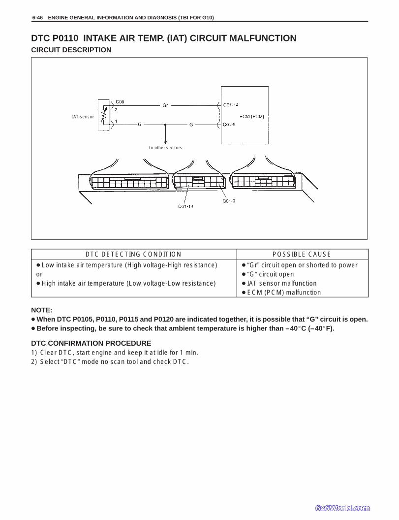
To other sensors
IAT sensor
6-46 ENGINE GENERAL INFORMATION AND DIAGNOSIS (TBI FOR G10)
DTC P0110 INTAKE AIR TEMP. (IAT) CIRCUIT MALFUNCTIONCIRCUIT DESCRIPTION
DTC DETECTING CONDITION POSSIBLE CAUSE
Low intake air temperature (High voltage-High resistance)or High intake air temperature (Low voltage-Low resistance)
“Gr” circuit open or shorted to power “G” circuit open IAT sensor malfunction ECM (PCM) malfunction
NOTE: When DTC P0105, P0110, P0115 and P0120 are indicated together, it is possible that “G” circuit is open. Before inspecting, be sure to check that ambient temperature is higher than –40C (–40F).
DTC CONFIRMATION PROCEDURE1) Clear DTC, start engine and keep it at idle for 1 min.2) Select “DTC” mode no scan tool and check DTC.

ENGINE GENERAL INFORMATION AND DIAGNOSIS (TBI FOR G10) 6-47
Fig. 1 for Step 2 Fig. 2 for Step 3 Fig. 3 for Step 4
Scan tool
DLC
INSPECTION
STEP ACTION YES NO
1 Was “ENGINE DIAG. FLOW TABLE” performed? Go to Step 2. Go to “ENGINE DIAG.FLOW TABLE”.
2 Check IAT Sensor and Its Circuit.1) Connect scan tool to DLC with ignition switch
OFF.2) Turn ignition switch ON.3) Check intake air temp. displayed on scan tool.
See Fig. 1.Is –40C (–40F) or 119C (246F) indicated?
Go to Step 3. Intermittent trouble.Check for intermittentreferring to “Intermittentand Poor Connection”in Section 0A.
3 Check Wire Harness.1) Disconnect IAT sensor connector with ignition
switch OFF.2) Check for proper connection to IAT sensor at
“Gr” and “G” wire terminals.3) If OK, then with ignition switch ON, is voltage
applied to “Gr” wire terminal about 4 – 6 V? SeeFig. 2.
Go to Step 5. “Gr” wire open orshorted to power, orpoor C01-14connection.If wire and connectionare OK, substitute aknown-good ECM(PCM) and recheck.
4 Does scan tool indicate –40C (–40F) at Step 2. Go to Step 6. Go to Step 5.
5 Check Wire Harness.1) Check intake air temp. displayed on scan tool
with ignition switch ON.Is –40C (–40F) indicated?
Replace IAT sensor. “Gr” wire shorted toground.If wire is OK, substitutea known-good ECM(PCM) and recheck.
6 Check Wire Harness.1) Using service wire, connect IAT sensor
connector terminals.2) Check intake air temp. displayed on scan tool
with ignition switch ON. See Fig. 3.Is 119C (246F) indicated?
Replace IAT sensor. “Gr” wire open or poorC01-9 connection.If wire and connectionare OK, substitute aknown-good ECM(PCM) and recheck.
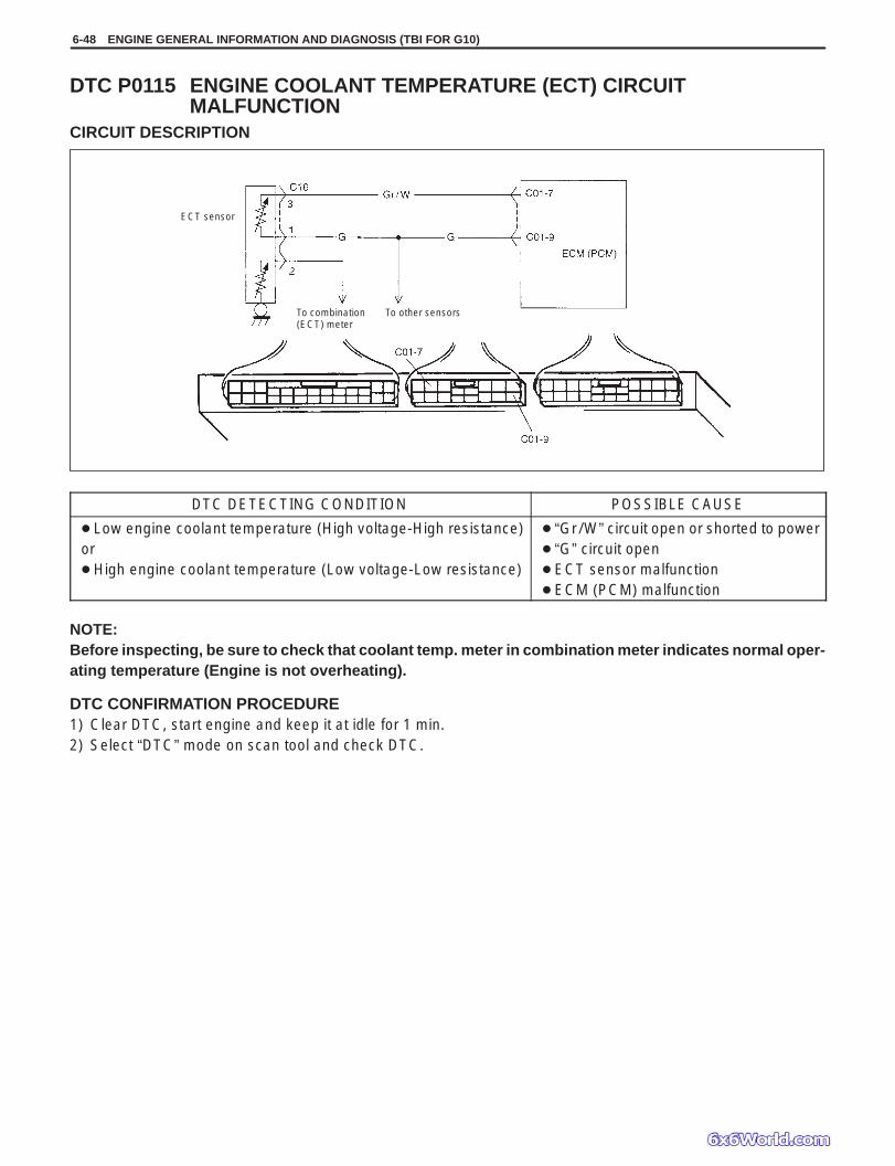
ECT sensor
To combination (ECT) meter
To other sensors
6-48 ENGINE GENERAL INFORMATION AND DIAGNOSIS (TBI FOR G10)
DTC P0115 ENGINE COOLANT TEMPERATURE (ECT) CIRCUITMALFUNCTION
CIRCUIT DESCRIPTION
DTC DETECTING CONDITION POSSIBLE CAUSE
Low engine coolant temperature (High voltage-High resistance)or High engine coolant temperature (Low voltage-Low resistance)
“Gr/W” circuit open or shorted to power “G” circuit open ECT sensor malfunction ECM (PCM) malfunction
NOTE:Before inspecting, be sure to check that coolant temp. meter in combination meter indicates normal oper-ating temperature (Engine is not overheating).
DTC CONFIRMATION PROCEDURE1) Clear DTC, start engine and keep it at idle for 1 min.2) Select “DTC” mode on scan tool and check DTC.

ENGINE GENERAL INFORMATION AND DIAGNOSIS (TBI FOR G10) 6-49
Fig. 1 for Step 2 Fig. 2 for Step 3 Fig. 3 for Step 4
Scan tool
DLC
INSPECTION
STEP ACTION YES NO
1 Was “ENGINE DIAG. FLOW TABLE” performed? Go to Step 2. Go to “ENGINE DIAG.FLOW TABLE”.
2 Check ECT Sensor and Its Circuit.1) Connect scan tool with ignition switch OFF.2) Turn ignition switch ON.3) Check engine coolant temp. displayed on scan
tool. See Fig. 1.Is –40C (–40F) or 119C (246F) indicated?
Go to Step 3. Intermittent trouble.Check for intermittentreferring to “Intermittentand Poor Connection”in Section 0 A.
3 Check Wire Harness.1) Disconnect ECT sensor connector.2) Check engine coolant temp. displayed on scan
tool.Is –40C (–40F) indicated?
Replace ECT sensor. “Gr/W” wire shorted toground.If wire is OK, substitutea known-good ECM(PCM) and recheck.
4 Does scan tool indicate –40C (–40F) at Step 2. Go to Step 6. Go to Step 5.
5 Check Wire Harness.1) Disconnect ECT sensor connector with
ignition switch OFF.2) Check for proper connection to ECT sensor at
“G” and “Gr/W” wire terminals.3) If OK, then with ignition switch ON, is voltage
applied to “G” wire terminal about 4 – 6 V?See Fig. 2.
Go to Step 4. “Gr/W” wire open orshorted to power, orpoor C01-7 connection.If wire and connectionare OK, substitute aknown-good ECM(PCM) and recheck.
6 Check Wire Harness.1) Using service wire, connect ECT sensor
connector terminals. See Fig. 3.2) Turn ignition switch ON and check engine
coolant temp. displayed on scan tool.Is 119C (246F) indicated?
Replace ECT sensor. “G” wire open orpoor C01-9 connection.If wire and connectionare OK, substitute aknown-good ECM(PCM) and recheck.

To other sensors
Throttle position sensor
To other sensors
6-50 ENGINE GENERAL INFORMATION AND DIAGNOSIS (TBI FOR G10)
DTC P0120 THROTTLE POSITION CIRCUIT MALFUNCTIONCIRCUIT DESCRIPTION
DTC DETECTING CONDITION POSSIBLE CAUSE
Signal voltage highor Signal voltage low
“G” circuit open “Lg/W” circuit open or shorted to ground “Lg” circuit open or shorted to power or ground TP sensor malfunction ECM (PCM) malfunction
NOTE: When DTC P0105, P0110, P0115 and/or P0120 are indicated together, it is possible that “G” circuit is
open. When DTC P0105, P0120 and/or P0510 are indicated together it is possible that “Lg” circuit is open.
DTC CONFIRMATION PROCEDURE1) Clear DTC, start engine and keep it at idle for 1 min.2) Select “DTC” mode on scan tool and check DTC.

ENGINE GENERAL INFORMATION AND DIAGNOSIS (TBI FOR G10) 6-51
Fig. 1 for Step 2 Fig. 2 for Step 3 Fig. 3 for Step 4
Scan tool
“Lg”
“Lg/W”
“3” “4”
“1”
INSPECTION
STEP ACTION YES NO
1 Was “ENGINE DIAG. FLOW TABLE”performed?
Go to Step 2. Go to “ENGINE DIAG.FLOW TABLE”.
2 Check TP Sensor and Its Circuit.1) Connect scan tool to DLC with ignition
switch OFF and then turn ignition switchON.
2) Check throttle valve opening percentagedisplayed on scan tool. See Fig. 1.
Is it displayed 2% or less?3) Check throttle valve opening percentage
displayed on scan tool while openingthrottle valve from idle position to full openposition. See Fig. 1.
Is it displayed 96% or higher?
Go to Step 3. Intermittent trouble.Check for intermittentreferring to “Intermittentand Poor Connection” inSection 0 A.
3 Check Wire Harness.1) Disconnect connector from TP sensor
with ignition switch OFF.2) Check for proper connection to TP sensor
at “Lg”, “Lg/W” and “G” wire terminal.3) If OK, then with ignition switch ON, check
voltage at each of “Lg” and “Lg/W” wireterminals. See Fig. 2.
Is voltage about 4 – 6 V at each terminal?
Go to Step 4. “Lg” wire open, “Lg”wire shorted to groundcircuit or power circuit or“G” wire, “Lg/W” wireopen or shorted to groundcircuit or poor C01-1 orC01-6 connection.If wire and connection areOK, substitute a known-good ECM (PCM) andrecheck.
4 Check TP Sensor.1) Check resistance between terminals of
TP sensor. See Fig. 3.Between 1 and 4: 2.87 – 5.33 kΩBetween 1 and 3: 100 Ω – 20 kΩ, varyingaccording to throttle valve opening.
Are measured values within specifications?
“G” wire open or poorC01–9 connection.If wire and connection areOK, substitute a known-good ECM (PCM) andrecheck.
Replace TP sensor.

To other sensors
Throttle position sensor
To other sensors
6-52 ENGINE GENERAL INFORMATION AND DIAGNOSIS (TBI FOR G10)
DTC P0121 THROTTLE POSITION CIRCUIT RANGE/PERFORMANCEPROBLEM
CIRCUIT DESCRIPTION
DTC DETECTING CONDITION POSSIBLE CAUSE
After engine warmed up. While vehicle running at specified engine speed. No change in intake manifold pressure (constant throttle opening) Difference between actual throttle opening (detected from TP sensor)
and opening calculated by ECM (PCM) (Obtained on the basis ofengine speed and intake manifold pressure) in larger than specifiedvalue.
2 driving cycle detection logic, continuous monitoring
TP sensor malfunction High resistance in the circuit ECM (PCM) malfunction
DTC CONFIRMATION PROCEDURE
WARNING: When performing a road test, select a place where there is no traffic or possibility of a traffic accident
and be very careful during testing to avoid occurrence of an accident. Road test should be carried out with 2 persons, a driver and a tester, on a level road.
1) Turn ignition switch OFF. Clear DTC with ignition switch ON, check vehicle and environmental condition for:– Altitude (barometric pressure): 2400 m, 8000 ft or less (560 mmHg, 75 kPa or more)– Ambient temp.: –10C, 14F or higher– Intake air temp.: 70C, 158F or lower– Engine coolant temp.: 70 – 110C, 158 – 230F
2) Warm up engine to normal operating temperature.3) Increase vehicle speed to 30 – 40 mph, 50 – 60 km/h in 3rd gear or “D” range and hold throttle valve at that
opening position for 1 min.4) Stop vehicle.5) Check DTC in “DTC” mode and pending DTC in “ON BOARD TEST” or “PENDING DTC” mode.

ENGINE GENERAL INFORMATION AND DIAGNOSIS (TBI FOR G10) 6-53
Fig. 1 for Step 2 Fig. 2 for Step 2
Fig. 3 for Step 3
Closed(condition “A”)
Fully open
Throttle Opening
Condition “A” Clearance between throttle lever andthrottle stop screw is less than 0.35 mm(0.014 in.).
clearance
“1”
“3” “4”
INSPECTION
STEP ACTION YES NO
1 Was “ENGINE DIAG. FLOW TABLE” performed? Go to Step 2. Go to “ENGINEDIAG. FLOWTABLE”.
2 Check TP Sensor and Its Circuit.1) Turn ignition switch OFF and connect SUZUKI scan tool to
DLC.2) Turn ignition switch ON and check TP sensor output
voltage when throttle valve is at idle position and fullyopened. See Fig. 1 and 2.
Dose voltage vary within specified value linearly as shown infigure?
If voltmeter wasused, checkterminal C01-6 forpoor connection.If OK, substitute aknown-good ECM(PCM) andrecheck.
Go to Step 3.
3 Check TP Sensor.1) Turn ignition switch OFF.2) Disconnect TP sensor connector.3) Check for proper connection to TP sensor at each terminal.4) If OK, then measure resistance between terminals and
check if each measured value is as specified below.See Fig. 3.Between 1 and 4: 2.87 – 5.33 kΩBetween 1 and 3: 100 Ω – 20 kΩ, varying according to
throttle valve opening.Are measured values as specified?
High resistance in“Lg”, “Lg/W” or“G” circuit.If wire andconnection areOK, substitute aknown-good ECM(PCM) andrecheck.
Replace TPsensor.

To generator
To other sensor
Mainfuse
Ignition switch
Heater
6-54 ENGINE GENERAL INFORMATION AND DIAGNOSIS (TBI FOR G10)
DTC P0130 HEATED OXYGEN SENSOR (HO2S) CIRCUIT MALFUNCTION(SENSOR-1)
CIRCUIT DESCRIPTION
DTC DETECTING CONDITION POSSIBLE CAUSE
When running at idle speed after engine warmed upand running at specified vehicle speed, HO2S-1output voltage does not go below 0.3 V or over0.6 V.
2 driving cycle detection logic, Monitoring once/1driving.
Heated oxygen sensor-1 malfunction “G” or “R” circuit open (poor connection) or short
DTC CONFIRMATION PROCEDURE
WARNING: When performing a road test, select a place where there is no traffic or possibility of a traffic accident
and be very careful during testing to avoid occurrence of an accident. Road test should be carried out with 2 persons, a driver and a tester.
1) Turn ignition switch OFF. Clear DTC with ignition switch ON, check vehicle and environmental condition for:– Altitude (barometric pressure): 2400 m, 8000 ft or less (560 mmHg, 75 kPa or more)– Ambient temp.: –10C, 14F or higher– Intake air temp.: 70C, 158F or lower
2) Warm up engine to normal operating temperature.3) Drive vehicle at 30 – 40 mph, 50 – 60 km/h for 2 min.4) Stop vehicle and run engine at idle for 2 min.5) Check DTC in “DTC” mode and pending DTC in “ON BOARD TEST” or “PENDING DTC” mode.
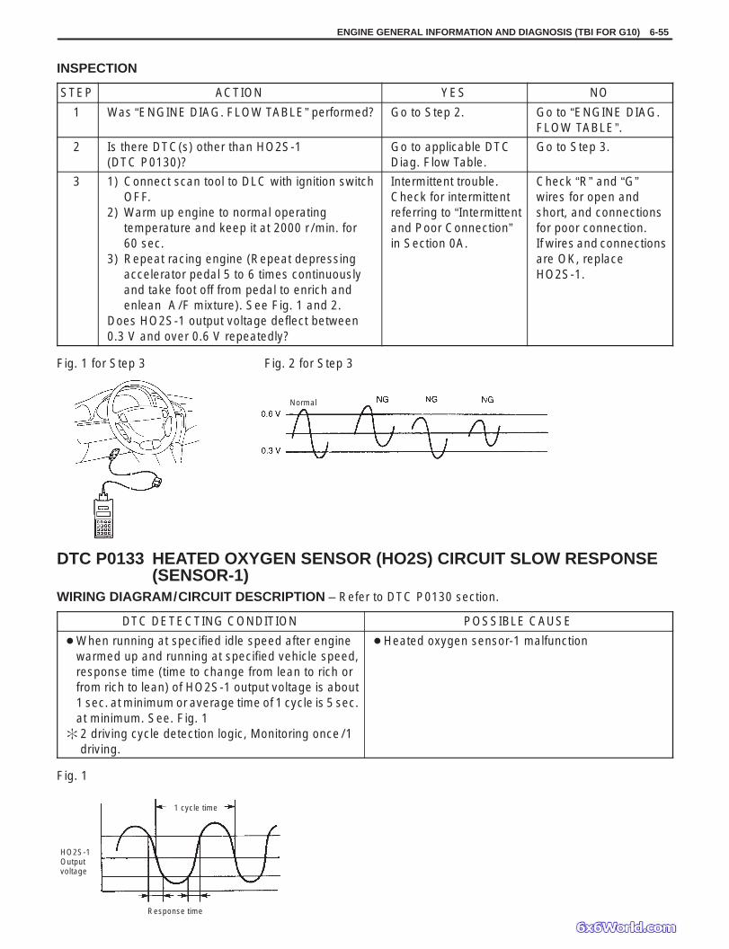
ENGINE GENERAL INFORMATION AND DIAGNOSIS (TBI FOR G10) 6-55
Fig. 1 for Step 3 Fig. 2 for Step 3
Normal
Fig. 1
HO2S-1Outputvoltage
1 cycle time
Response time
INSPECTION
STEP ACTION YES NO
1 Was “ENGINE DIAG. FLOW TABLE” performed? Go to Step 2. Go to “ENGINE DIAG.FLOW TABLE”.
2 Is there DTC(s) other than HO2S-1(DTC P0130)?
Go to applicable DTCDiag. Flow Table.
Go to Step 3.
3 1) Connect scan tool to DLC with ignition switchOFF.
2) Warm up engine to normal operatingtemperature and keep it at 2000 r/min. for60 sec.
3) Repeat racing engine (Repeat depressingaccelerator pedal 5 to 6 times continuouslyand take foot off from pedal to enrich andenlean A/F mixture). See Fig. 1 and 2.
Does HO2S-1 output voltage deflect between0.3 V and over 0.6 V repeatedly?
Intermittent trouble.Check for intermittentreferring to “Intermittentand Poor Connection”in Section 0A.
Check “R” and “G”wires for open andshort, and connectionsfor poor connection.If wires and connectionsare OK, replaceHO2S-1.
DTC P0133 HEATED OXYGEN SENSOR (HO2S) CIRCUIT SLOW RESPONSE(SENSOR-1)
WIRING DIAGRAM/CIRCUIT DESCRIPTION – Refer to DTC P0130 section.
DTC DETECTING CONDITION POSSIBLE CAUSE
When running at specified idle speed after enginewarmed up and running at specified vehicle speed,response time (time to change from lean to rich orfrom rich to lean) of HO2S-1 output voltage is about1 sec. at minimum or average time of 1 cycle is 5 sec.at minimum. See. Fig. 1
2 driving cycle detection logic, Monitoring once/1driving.
Heated oxygen sensor-1 malfunction
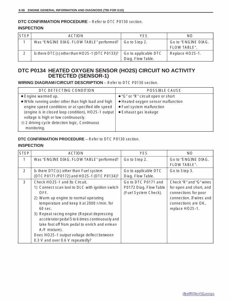
6-56 ENGINE GENERAL INFORMATION AND DIAGNOSIS (TBI FOR G10)
DTC CONFIRMATION PROCEDURE – Refer to DTC P0130 section.
INSPECTION
STEP ACTION YES NO
1 Was “ENGINE DIAG. FLOW TABLE” performed? Go to Step 2. Go to “ENGINE DIAG.FLOW TABLE”.
2 Is there DTC(s) other than HO2S-1 (DTC P0133)? Go to applicable DTCDiag. Flow Table.
Replace HO2S-1.
DTC P0134 HEATED OXYGEN SENSOR (HO2S) CIRCUIT NO ACTIVITYDETECTED (SENSOR-1)
WIRING DIAGRAM/CIRCUIT DESCRIPTION – Refer to DTC P0130 section.
DTC DETECTING CONDITION POSSIBLE CAUSE
Engine warmed up. While running under other than high load and high
engine speed conditions or at specified idle speed(engine is in closed loop condition), HO2S-1 outputvoltage is high or low continuously.
2 driving cycle detection logic, Continuousmonitoring.
“G” or “R” circuit open or short Heated oxygen sensor malfunction Fuel system malfunction Exhaust gas leakage
DTC CONFIRMATION PROCEDURE – Refer to DTC P0130 section.
INSPECTION
STEP ACTION YES NO
1 Was “ENGINE DIAG. FLOW TABLE” performed? Go to Step 2. Go to “ENGINE DIAG.FLOW TABLE”.
2 Is there DTC(s) other than Fuel system(DTC P0171/P0172) and HO2S-1 (DTC P0134)?
Go to applicable DTCDiag. Flow Table.
Go to Step 3.
3 Check HO2S-1 and Its Circuit.1) Connect scan tool to DLC with ignition switch
OFF.2) Warm up engine to normal operating
temperature and keep it at 2000 r/min. for60 sec.
3) Repeat racing engine (Repeat depressingaccelerator pedal 5 to 6 times continuously andtake foot off from pedal to enrich and enleanA/F mixture).
Does HO2S-1 output voltage deflect between0.3 V and over 0.6 V repeatedly?
Go to DTC P0171 andP0172 Diag. Flow Table(Fuel System Check).
Check “R” and “G” wiresfor open and short, andconnections for poorconnection. If wires andconnections are OK,replace HO2S-1.

To generator
To other sensor
Heater
Ignitionswitch
Mainfuse
“IG COIL METER”
ENGINE GENERAL INFORMATION AND DIAGNOSIS (TBI FOR G10) 6-57
DTC P0135 HEATED OXYGEN SENSOR (HO2S) HEATER CIRCUITMALFUNCTION (SENSOR-1)
CIRCUIT DESCRIPTION
DTC DETECTING CONDITION POSSIBLE CAUSE
DTC will set when A or B condition is met.A: Low voltage at terminal C01-8 when engine is
running at high load.B: High voltage at terminal C01-8 when engine is
running under condition other than above. 2 driving cycle detection logic, Continuous
monitoring.
HO2S-1 heater circuit open or shorted to ground ECM (PCM) malfunction
DTC CONFIRMATION PROCEDURE
WARNING: When performing a road test, select a place where there is no traffic or possibility of a traffic accident
and be very careful during testing to avoid occurrence of an accident. Road test should be carried out with 2 persons, a driver and a tester.
1) Turn ignition switch OFF.2) Clear DTC with ignition switch ON, start engine and keep it at idle for 1 min.3) Start vehicle and depress accelerator pedal fully for 5 sec. or longer.4) Stop vehicle.5) Check DTC in “DTC” mode and pending DTC in “ON BOARD TEST” or “PENDING DTC” mode.

6-58 ENGINE GENERAL INFORMATION AND DIAGNOSIS (TBI FOR G10)
Fig. 1 for Step 2 Fig. 2 for Step 3C01-8
INSPECTION
STEP ACTION YES NO
1 Was “ENGINE DIAG. FLOW TABLE” performed? Go to Step 2. Go to “ENGINE DIAG.FLOW TABLE”.
2 Check Heater for Operation.1) Check voltage at terminal C01-8. See Fig. 1.2) Warm up engine to normal operating temperature.3) Stop engine.4) Turn ignition switch ON and Check voltage at
Intermittent troubleCheck for intermittentreferring to“Intermittent andPoor Connection”
Go to Step 3.
terminal C01-8. See Fig. 1. Voltage should beover 10 V.
5) Start engine, run it at idle and check voltage at thesame terminal. Voltage should be below 1.9 V.
Are check results are specified?
in Section 0A.
3 Check Heater of Sensor-1.1) Disconnect HO2S-1 coupler with ignition switch
OFF.2) Check for proper connection to HO2S-1 at “B/W”
and “P/B” wire terminals.3) If OK, then check heater resistance. See Fig. 2.Is it 11.7 – 14.3 Ω at 20C, 68F?
“P/B” wire open orshorted to ground orpoor connection atC01-8. If wire andconnection are OK,substitute aknown-good ECM(PCM) and recheck.
Replace HO2S-1.

To other sensor
Heater
Ignitionswitch
Mainfuse
“IG COIL METER”
To ignition coil
To other sensor
ENGINE GENERAL INFORMATION AND DIAGNOSIS (TBI FOR G10) 6-59
DTC P0136 HEATED OXYGEN SENSOR (HO2S) CIRCUIT MALFUNCTION(SENSOR-2)
CIRCUIT DESCRIPTION
DTC DETECTING CONDITION POSSIBLE CAUSE
DTC will set when A or B condition is detected.A. Max. output voltage of HO2S-2 is lower than specified value or
Min. output voltage is higher than specified value while vehicledriving.
B. Engine is warmed up and HO2S-2 voltage is 4.5 V or more.(circuit open)
2 driving cycle detection logic, monitoring once/1 driving.
Exhaust gas leakage “G” or “R” circuit open or short Heated oxygen sensor-2 malfunction Fuel system malfunction

6-60 ENGINE GENERAL INFORMATION AND DIAGNOSIS (TBI FOR G10)
Usual driving: Driving at 30 – 40 mph, 50 – 60 km/h including short stop according to traffic signal. (under driving condition other than high-load,high-engine speed, rapid accelerating and decelerating)
1) 2) 3) 4) 5) 6) 7) 8) 9) 10) 11)and
50 mph(80 km / h)
Above 20 mph(32 km / h)
Usual driving
DTC CONFIRMATION PROCEDURE
WARNING: When performing a road test, select a place where there is no traffic or possibility of a traffic accident
and be very careful during testing to avoid occurrence of an accident. Road test should be carried out with 2 persons, a driver and a tester, on a level road.
1) Turn ignition switch OFF.Clear DTC with ignition switch ON, check vehicle and environmental condition for:– Altitude (barometric pressure): 2400 m, 8000 ft or less (560 mmHg, 75 kPa or more)– Ambient temp.: –10C, 14F or higher– Intake air temp.: 70C, 158F or lower– No exhaust gas leakage and loose connection
2) Warm up engine to normal operating temperature.3) Drive vehicle under usual driving condition for 5 min. and check HO2S-2 output voltage and “short term fuel
trim” with “Data List” mode on scan tool, and write it down.4) Stop vehicle (don’t turn ignition switch OFF).5) Increase vehicle speed to higher than 20 mph, 32 km/h and then stop vehicle.6) Repeat above steps 5) 4 times.7) Increase vehicle speed to about 50 mph (80 km/h) in 3rd gear or 2 range.8) Release accelerator pedal and with engine brake applied, keep vehicle coasting (fuel cut condition) for 10sec.
or more.9) Stop vehicle (don’t turn ignition switch OFF) and run engine at idle for 2 min.
After this step 9), if “Oxygen Sensor Monitoring TEST COMPLETED” is displayed in “READINESS TESTS”mode and DTC is not displayed in “DTC” mode, confirmation test is completed.If “TEST NOT COMPLTD” is still being displayed, proceed to next step 10).
10) Drive vehicle under usual driving condition for 10 min. (or vehicle is at a stop and run engine at idle for 10 min.or longer)
11) Stop vehicle (don’t turn ignition switch OFF). Confirm test results according to “Test Result Confirmation FlowTable” in “DTC CONFIRMATION PROCEDURE” of DTC P0420.

ENGINE GENERAL INFORMATION AND DIAGNOSIS (TBI FOR G10) 6-61
INSPECTION
STEP ACTION YES NO
1 Was “ENGINE DIAG. FLOW TABLE” performed? Go to Step 2. Go to “ENGINE DIAG.FLOW TABLE”.
2 Check exhaust system for leakage, looseconnection and damage.Is it good condition?
Go to Step 3. Repair or replace.
3 Check HO2S-2 and Its Circuit.Was HO2S-2 output voltage indicated on scantool in step 3) of DTC confirmation test lessthan 1.275 V?
Go to Step 4. “Lg/B” or “R” circuitopen or HO2S-2malfunction.
4 Check Short Term Fuel Trim.Did short term fuel trim very within –20 – +20%range in step 3) of DTC confirmation test?
Check “R” and “Lg/B”wire for open and short,and connection for poorconnection. If wire andconnection are OK,replace HO2S-2.
Check fuel system. Goto DTC P0171/P0172Diag. Flow Table.

6-62 ENGINE GENERAL INFORMATION AND DIAGNOSIS (TBI FOR G10)
To other sensor
Heater
Ignitionswitch
Mainfuse
“IG COIL METER”
To ignition coil
To other sensor
DTC P0141 HEATED OXYGEN SENSOR (HO2S) HEATER CIRCUITMALFUNCTION (SENSOR-2)
CIRCUIT DESCRIPTION
DTC DETECTING CONDITION POSSIBLE CAUSE
DTC will set when A or B condition it met.A. Low voltage at terminal C02-19 for specified time after engine
start or while engine running at high load.B. High voltage at terminal C02-19 while engine running under
other than above condition. 2 driving cycle detection logic, continuous monitoring.
HO2S-2 heater circuit open or shortedto ground
ECM (PCM) malfunction
DTC CONFIRMATION PROCEDURE1) Turn ignition switch OFF once and then ON.2) Clear DTC, start engine and warm up engine to normal operating temperature.3) Keep it at 2000 r/min for 2 min.4) Check pending DTC in “ON BOARD TEST” or “PENDING DTC” mode and DTC in “DTC” mode.
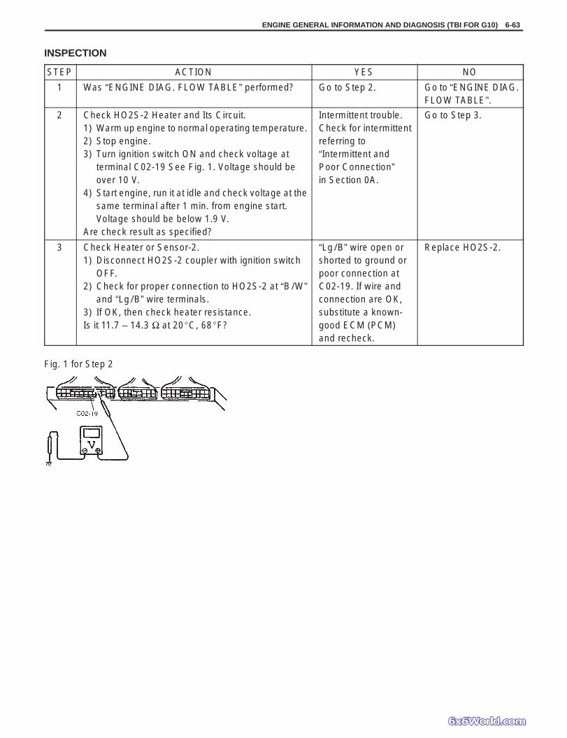
ENGINE GENERAL INFORMATION AND DIAGNOSIS (TBI FOR G10) 6-63
Fig. 1 for Step 2
INSPECTION
STEP ACTION YES NO
1 Was “ENGINE DIAG. FLOW TABLE” performed? Go to Step 2. Go to “ENGINE DIAG.FLOW TABLE”.
2 Check HO2S-2 Heater and Its Circuit.1) Warm up engine to normal operating temperature.2) Stop engine.3) Turn ignition switch ON and check voltage at
terminal C02-19 See Fig. 1. Voltage should beover 10 V.
4) Start engine, run it at idle and check voltage at thesame terminal after 1 min. from engine start.Voltage should be below 1.9 V.
Are check result as specified?
Intermittent trouble.Check for intermittentreferring to“Intermittent andPoor Connection”in Section 0A.
Go to Step 3.
3 Check Heater or Sensor-2.1) Disconnect HO2S-2 coupler with ignition switch
OFF.2) Check for proper connection to HO2S-2 at “B/W”
and “Lg/B” wire terminals.3) If OK, then check heater resistance.Is it 11.7 – 14.3 Ω at 20C, 68F?
“Lg/B” wire open orshorted to ground orpoor connection atC02-19. If wire andconnection are OK,substitute a known-good ECM (PCM)and recheck.
Replace HO2S-2.

6-64 ENGINE GENERAL INFORMATION AND DIAGNOSIS (TBI FOR G10)
Sensedinformation
Exhaustgas
Fuelinjector
A / Fmixture
Signal to decrease amount of fuel injection
Signal to increase amount of fuel injection
High voltage
Low voltage
INJECTORHEATEDOXYGENSENSOR-1
A / F mixturebecomesricher
Oxygenconcentrationdecreases
A / F mixturebecomesleaner
Oxygenconcentrationincreases
ECM(PCM)
ECM(PCM)
Mainfuse
Ignition switch“IG COIL METER”
Main relay
To other circuits
Injector resistor To othersensor
Fuelinjector
Heated oxygen sensor-1
HO2S-1
DTC P0171 FUEL SYSTEM TOO LEANDTC P0172 FUEL SYSTEM TOO RICHCIRCUIT DESCRIPTION
DTC DETECTING CONDITION POSSIBLE CAUSE
When following condition occurs while engine running underclosed loop condition.– Air/ fuel ratio too lean
Total fuel trim (short and long terms added) ismore than 30%
or
– Air/ fuel ratio too rich(Total fuel trim is less than –30%)
2 driving cycle detection logic, continuous monitoring.
Vacuum leaks (air drawn in). Exhaust gas leakage. Heated oxygen sensor-1 circuit
malfunction. Fuel pressure out of specification. Fuel injector malfunction (clogged or
leakage). MAP sensor poor performance. ECT sensor poor performance. IAT sensor poor performance. TP sensor poor performance. EVAP control system malfunction. PCV valve malfunction.

ENGINE GENERAL INFORMATION AND DIAGNOSIS (TBI FOR G10) 6-65
DTC CONFIRMATION PROCEDURE
WARNING: When performing a road test, select a place where there is no traffic or possibility of a traffic accident
and be very careful during testing to avoid occurrence of an accident. Road test should be carried out with 2 persons, a driver and a tester on a level road.
1) Turn ignition switch OFF.2) Clear DTC with ignition switch ON.3) Check vehicle and environmental condition for:
– Altitude (barometric pressure): 2400 m, 8000 ft or less (560 mmHg, 75 kPa or more)– Ambient temp.: –10C, 14F or higher– Intake air temp.: 70C, 158F or lower
4) Start engine and drive vehicle under usual driving condition (described in DTC confirmation procedure of DTCP0136) for 5 min. or longer and until engine is warmed up to normal operating temperature.
5) Keep vehicle speed at 30 – 40 mph, 50 – 60 km/h in 5th gear or “D” range for 5 min. or more.6) Stop vehicle (do not turn ignition switch OFF).7) Check pending DTC in “ON BOARD TEST” or “PENDING DTC” mode and DTC in “DTC” mode.
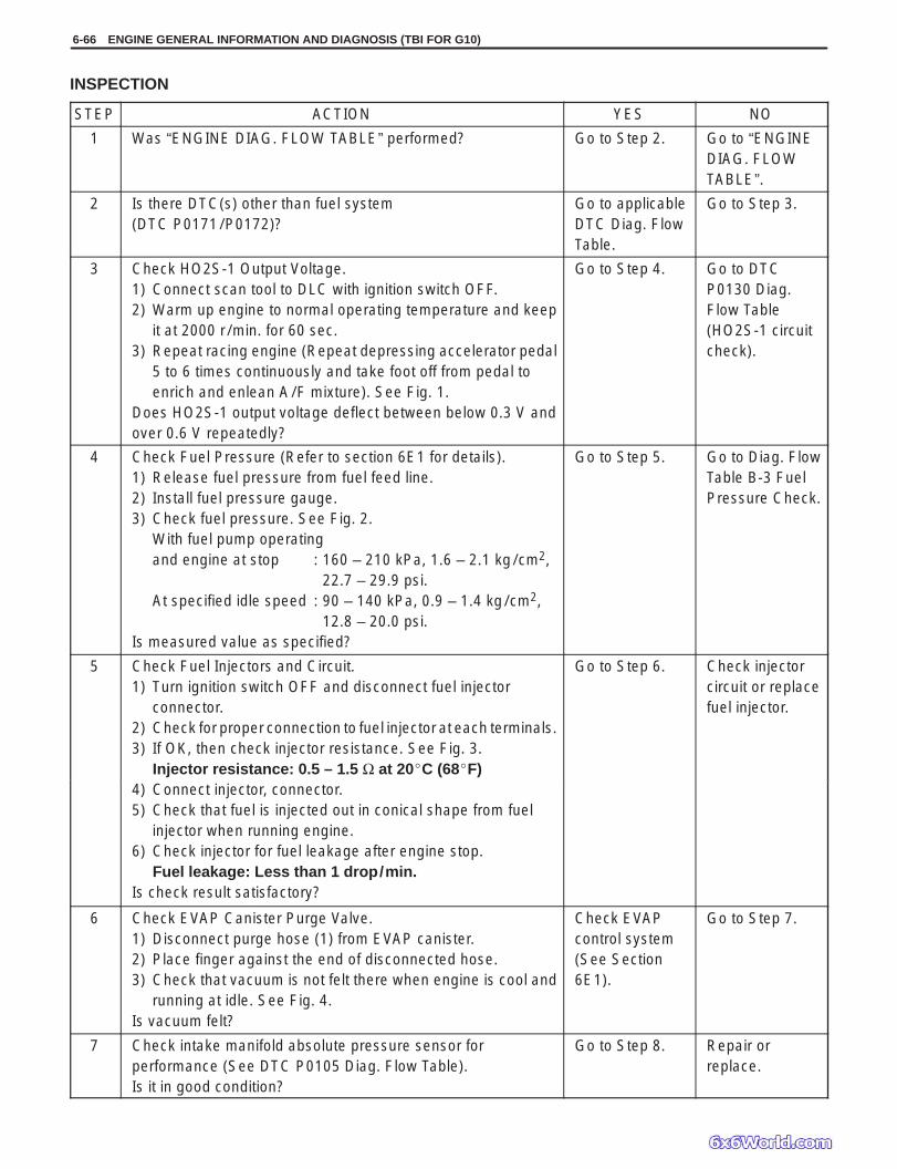
6-66 ENGINE GENERAL INFORMATION AND DIAGNOSIS (TBI FOR G10)
INSPECTION
STEP ACTION YES NO
1 Was “ENGINE DIAG. FLOW TABLE” performed? Go to Step 2. Go to “ENGINEDIAG. FLOWTABLE”.
2 Is there DTC(s) other than fuel system(DTC P0171/P0172)?
Go to applicableDTC Diag. FlowTable.
Go to Step 3.
3 Check HO2S-1 Output Voltage.1) Connect scan tool to DLC with ignition switch OFF.2) Warm up engine to normal operating temperature and keep
it at 2000 r/min. for 60 sec.3) Repeat racing engine (Repeat depressing accelerator pedal
5 to 6 times continuously and take foot off from pedal toenrich and enlean A/F mixture). See Fig. 1.
Does HO2S-1 output voltage deflect between below 0.3 V andover 0.6 V repeatedly?
Go to Step 4. Go to DTCP0130 Diag.Flow Table(HO2S-1 circuitcheck).
4 Check Fuel Pressure (Refer to section 6E1 for details).1) Release fuel pressure from fuel feed line.2) Install fuel pressure gauge.3) Check fuel pressure. See Fig. 2.
With fuel pump operatingand engine at stop : 160 – 210 kPa, 1.6 – 2.1 kg/cm2,
22.7 – 29.9 psi.At specified idle speed : 90 – 140 kPa, 0.9 – 1.4 kg/cm2,
12.8 – 20.0 psi.Is measured value as specified?
Go to Step 5. Go to Diag. FlowTable B-3 FuelPressure Check.
5 Check Fuel Injectors and Circuit.1) Turn ignition switch OFF and disconnect fuel injector
connector.2) Check for proper connection to fuel injector at each terminals.3) If OK, then check injector resistance. See Fig. 3.
Injector resistance: 0.5 – 1.5 Ω at 20C (68F)
Go to Step 6. Check injectorcircuit or replacefuel injector.
4) Connect injector, connector.5) Check that fuel is injected out in conical shape from fuel
injector when running engine.6) Check injector for fuel leakage after engine stop.
Fuel leakage: Less than 1 drop/min.Is check result satisfactory?
6 Check EVAP Canister Purge Valve.1) Disconnect purge hose (1) from EVAP canister.2) Place finger against the end of disconnected hose.3) Check that vacuum is not felt there when engine is cool and
running at idle. See Fig. 4.Is vacuum felt?
Check EVAPcontrol system(See Section6E1).
Go to Step 7.
7 Check intake manifold absolute pressure sensor forperformance (See DTC P0105 Diag. Flow Table).Is it in good condition?
Go to Step 8. Repair orreplace.
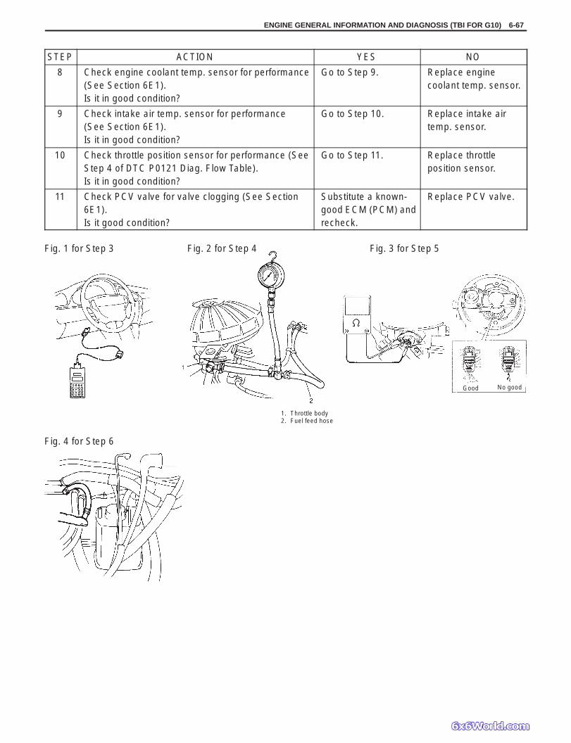
ENGINE GENERAL INFORMATION AND DIAGNOSIS (TBI FOR G10) 6-67
Fig. 1 for Step 3 Fig. 2 for Step 4 Fig. 3 for Step 5
Fig. 4 for Step 6
1. Throttle body2. Fuel feed hose
Good No good
STEP ACTION YES NO
8 Check engine coolant temp. sensor for performance(See Section 6E1).Is it in good condition?
Go to Step 9. Replace enginecoolant temp. sensor.
9 Check intake air temp. sensor for performance(See Section 6E1).Is it in good condition?
Go to Step 10. Replace intake airtemp. sensor.
10 Check throttle position sensor for performance (SeeStep 4 of DTC P0121 Diag. Flow Table).Is it in good condition?
Go to Step 11. Replace throttleposition sensor.
11 Check PCV valve for valve clogging (See Section6E1).Is it good condition?
Substitute a known-good ECM (PCM) andrecheck.
Replace PCV valve.

Ignition coil Igniter
Ignition switch
Mainfuse
Injector resistor Fuel injector
Crankshaftposition sensor
Camshaftposition sensor
Groundat engine
“I / G COIL METER”
Main relay
6-68 ENGINE GENERAL INFORMATION AND DIAGNOSIS (TBI FOR G10)
DTC P0300 RANDOM MISFIRE DETECTED (Misfire detected at 2 or morecylinders)
DTC P0301 CYLINDER 1 MISFIRE DETECTEDDTC P0302 CYLINDER 2 MISFIRE DETECTEDDTC P0303 CYLINDER 3 MISFIRE DETECTED
CIRCUIT DESCRIPTIONECM (PCM) monitors crankshaft revolution speed and engine speed via the crankshaft position sensor and cylin-der No. via the camshaft position sensor. Then it calculates the change in the crankshaft revolution speed and fromhow many times such change occurred in every 200 or 1000 engine revolutions, it detects occurrence of misfire.When ECM (PCM) detects a misfire (misfire rate per 200 revolutions) which can cause overheat and damage tothe three way catalytic converter, it makes the malfunction indicator lamp (MIL) flash as long as misfire occurs atthat rate.After that, however, when the misfire rate drops, MIL remains ON until it has been judged as normal 3 times underthe same driving conditions.Also, when ECM (PCM) detects a misfire (misfire rate per 1000 revolutions) which will not cause damage to threeway catalytic converter but can cause exhaust emission to be deteriorated, it makes MIL light according to the 2driving cycle detection logic.

ENGINE GENERAL INFORMATION AND DIAGNOSIS (TBI FOR G10) 6-69
Belowspecified value
DTC DETECTING CONDITION POSSIBLE CAUSE
Engine under other than high revolution condition Not on rough road Engine speed changing rate Manifold absolute
pressure changing rate Throttle opening changing rate Misfire rate per 200 or 1000 engine revolutions (how
much and how often crankshaft revolution speedchanges) is higher than specified value
Engine overheating Vacuum leaks (air inhaling) from air intake system Ignition system malfunction (spark plug(s), high-
tension cord(s), ignition coil assembly) Fuel pressure out of specification Fuel injector malfunction (clogged or leakage) Engine compression out of specification Valve lash (clearance) out of specification Manifold absolute pressure sensor malfunction Engine coolant temp. sensor malfunction PCV valve malfunction EVAP control system malfunction
DTC CONFIRMATION PROCEDURE
WARNING: When performing a road test, select a place where there is no traffic or possibility of a traffic accident
and be very careful during testing to avoid occurrence of an accident. Road test should be carried out with 2 persons, a driver and a tester.
1) Turn ignition switch OFF.2) Clear DTC with ignition switch ON.3) Check vehicle and environmental condition for:
– Altitude (barometric pressure): 2400 m, 8000 ft or less (560 mmHg, 75 kPa or more)– Ambient temp.: –10C, 14F or higher– Intake air temp.: 70C, 158F or lower– Engine coolant temp.: –10 – 110C, 14 – 230F
4) Start engine and keep it at idle for 2 min. or more.5) Check DTC in “DTC” mode and pending DTC in “ON BOARD TEST” or “PENDING DTC” mode.6) If DTC is not detected at idle, consult usual driving based on information obtained in “Customer complaint analy-
sis” and “Freeze frame data check”.
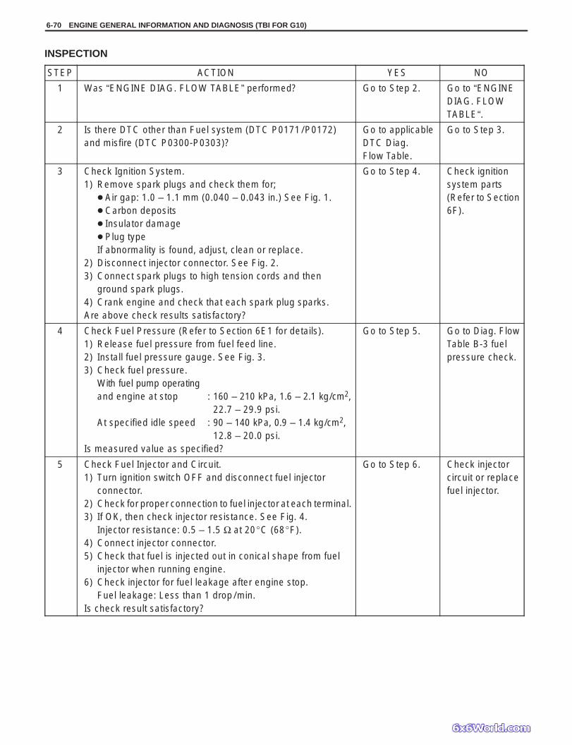
6-70 ENGINE GENERAL INFORMATION AND DIAGNOSIS (TBI FOR G10)
INSPECTION
STEP ACTION YES NO
1 Was “ENGINE DIAG. FLOW TABLE” performed? Go to Step 2. Go to “ENGINEDIAG. FLOWTABLE“.
2 Is there DTC other than Fuel system (DTC P0171/P0172)and misfire (DTC P0300-P0303)?
Go to applicableDTC Diag.Flow Table.
Go to Step 3.
3 Check Ignition System.1) Remove spark plugs and check them for;
Air gap: 1.0 – 1.1 mm (0.040 – 0.043 in.) See Fig. 1. Carbon deposits Insulator damage Plug typeIf abnormality is found, adjust, clean or replace.
2) Disconnect injector connector. See Fig. 2.3) Connect spark plugs to high tension cords and then
ground spark plugs.4) Crank engine and check that each spark plug sparks.Are above check results satisfactory?
Go to Step 4. Check ignitionsystem parts(Refer to Section6F).
4 Check Fuel Pressure (Refer to Section 6E1 for details).1) Release fuel pressure from fuel feed line.2) Install fuel pressure gauge. See Fig. 3.3) Check fuel pressure.
With fuel pump operatingand engine at stop : 160 – 210 kPa, 1.6 – 2.1 kg/cm2,
22.7 – 29.9 psi.At specified idle speed : 90 – 140 kPa, 0.9 – 1.4 kg/cm2,
12.8 – 20.0 psi.Is measured value as specified?
Go to Step 5. Go to Diag. FlowTable B-3 fuelpressure check.
5 Check Fuel Injector and Circuit.1) Turn ignition switch OFF and disconnect fuel injector
connector.2) Check for proper connection to fuel injector at each terminal.3) If OK, then check injector resistance. See Fig. 4.
Injector resistance: 0.5 – 1.5 Ω at 20C (68F).4) Connect injector connector.5) Check that fuel is injected out in conical shape from fuel
injector when running engine.6) Check injector for fuel leakage after engine stop.
Fuel leakage: Less than 1 drop/min.Is check result satisfactory?
Go to Step 6. Check injectorcircuit or replacefuel injector.

ENGINE GENERAL INFORMATION AND DIAGNOSIS (TBI FOR G10) 6-71
1. Throttle body2. Fuel feed hose
Good No good
1. Injector connector
STEP ACTION YES NO
6 Check PCV valve for clogging (See Section 6E1).Is it in good condition?
Go to Step 7. Replace PCV valve.
7 Check EVAP Canister Purge Valve for Closing.1) Disconnect purge hose (1) from EVAP canister.2) Place finger against the end of disconnected hose.3) Check that vacuum is not felt there, when engine is
cool and running at idle. See Fig. 5.Is vacuum felt?
Check EVAPcontrol system(See Section 6E1).
Go to Step 8.
8 Check intake manifold pressure sensor for performance(See Section 6E1).Is it in good condition?
Go to Step 9. Repair or replace.
9 Check engine coolant temp. sensor for performance(See Section 6E1).Is it in good condition?
Go to Step 10. Replace enginecoolant temp.sensor.
10 Check parts or system which can cause engine roughidle or poor performance.– Engine compression (See Section 6A).– Valve lash (See Section 6A).– Valve timing (Timing belt installation. See Section 6A).Are they in good condition?
Check wire harnessand connection ofECM (PCM) ground,ignition system andfuel injector forintermittent openand short.
Repair or replace.
Fig. 1 for Step 3 Fig. 2 for Step 3 Fig. 3 for Step 4
Fig. 4 for Step 5 Fig. 5 for Step 7

Oscilloscope Waveforms
Crankshafttiming belt pulley
CKPsensor
2V/Div.
5ms/Div.Waveforms at specified idle speed
6-72 ENGINE GENERAL INFORMATION AND DIAGNOSIS (TBI FOR G10)
DTC P0335 CRANKSHAFT POSITION (CKP) SENSOR CIRCUIT MALFUNCTIONCIRCUIT DESCRIPTION
DTC DETECTING CONDITION POSSIBLE CAUSE
No CKP sensor signal during 1 revolution ofcamshaft.
CKP sensor circuit open or short. Crankshaft timing belt pulley teeth damaged. CKP sensor malfunction, foreign material being
attached or improper installation. ECM (PCM) malfunction.
ReferenceConnect oscilloscope between terminals C01-3 (+) and C01-11 (–) of ECM (PCM) connector connected to ECM(PCM) and check CKP sensor signal.
DTC CONFIRMATION PROCEDURE1) Clear DTC, start engine and keep it at idle for 1 min.2) Select “DTC” mode on scan tool and check DTC.

ENGINE GENERAL INFORMATION AND DIAGNOSIS (TBI FOR G10) 6-73
INSPECTION
STEP ACTION YES NO
1 Was “ENGINE DIAG. FLOW TABLE” performed? Go to Step 2. Go to “ENGINE DIAG.FLOW TABLE”.
2 Check CKP Sensor for Resistance.1) Disconnect CKP sensor connector with ignition
switch OFF.2) Then check for proper connection to CKP sensor
at “W/B” and “W/R” wire terminals.3) If OK, measure sensor resistance between
terminals. See Fig. 1.CKP sensor resistance: 360 – 460 Ω
at 20C, (68F)4) Measure resistance between each terminal and
ground.Insulation resistance: 1 MΩ or more.
Were measured resistance valves in step 3) and 4)as specified?
Go to Step 3. Replace CKP sensor.
3 Check visually CKP sensor and pulley for thefollowing. See Fig. 2.
Damage No foreign material attached. Correct installation.
Are they in good condition?
“W/B” or “W/R” wireopen or shorted toground, or poorconnection at C01-3or C01-11.If wire and connectionare OK, intermittenttrouble or faulty ECM(PCM).Recheck forintermittent referringto “Intermittent andPoor Connection” inSection 0A.
Clean, repair orreplace.
Fig. 1 for Step 2 Fig. 2 for Step 3
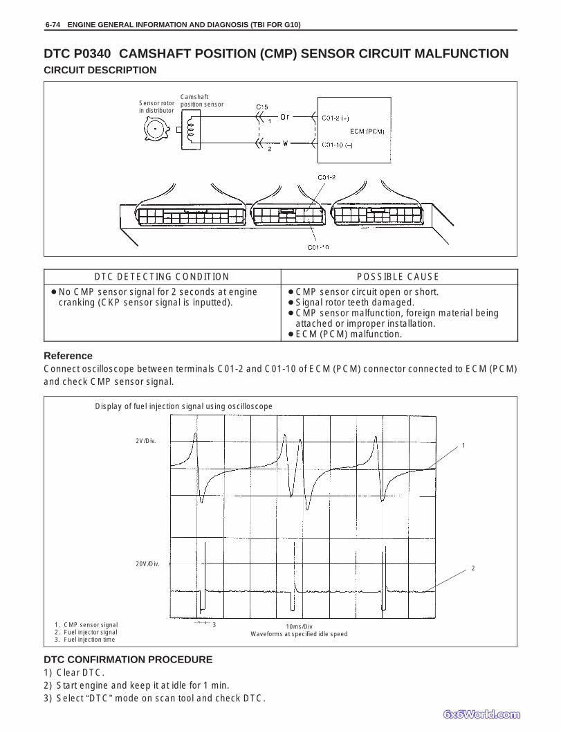
Display of fuel injection signal using oscilloscope
1. CMP sensor signal2. Fuel injector signal3. Fuel injection time
2V/Div.
20V/Div.
1
2
10ms/DivWaveforms at specified idle speed
3
Sensor rotorin distributor
Camshaftposition sensor
6-74 ENGINE GENERAL INFORMATION AND DIAGNOSIS (TBI FOR G10)
DTC P0340 CAMSHAFT POSITION (CMP) SENSOR CIRCUIT MALFUNCTIONCIRCUIT DESCRIPTION
DTC DETECTING CONDITION POSSIBLE CAUSE
No CMP sensor signal for 2 seconds at enginecranking (CKP sensor signal is inputted).
CMP sensor circuit open or short. Signal rotor teeth damaged. CMP sensor malfunction, foreign material being
attached or improper installation. ECM (PCM) malfunction.
ReferenceConnect oscilloscope between terminals C01-2 and C01-10 of ECM (PCM) connector connected to ECM (PCM)and check CMP sensor signal.
DTC CONFIRMATION PROCEDURE1) Clear DTC.2) Start engine and keep it at idle for 1 min.3) Select “DTC” mode on scan tool and check DTC.
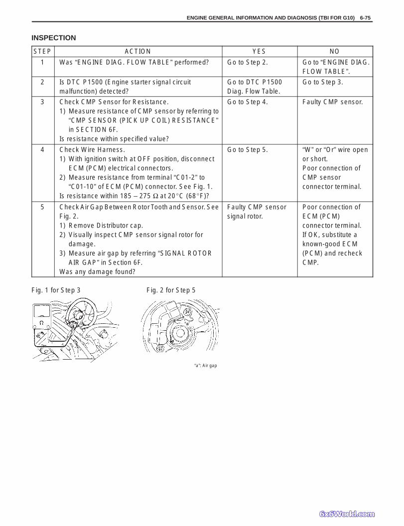
ENGINE GENERAL INFORMATION AND DIAGNOSIS (TBI FOR G10) 6-75
Fig. 1 for Step 3 Fig. 2 for Step 5
“a”: Air gap
INSPECTION
STEP ACTION YES NO
1 Was “ENGINE DIAG. FLOW TABLE” performed? Go to Step 2. Go to “ENGINE DIAG.FLOW TABLE”.
2 Is DTC P1500 (Engine starter signal circuitmalfunction) detected?
Go to DTC P1500Diag. Flow Table.
Go to Step 3.
3 Check CMP Sensor for Resistance.1) Measure resistance of CMP sensor by referring to
“CMP SENSOR (PICK UP COIL) RESISTANCE”in SECTION 6F.
Is resistance within specified value?
Go to Step 4. Faulty CMP sensor.
4 Check Wire Harness.1) With ignition switch at OFF position, disconnect
ECM (PCM) electrical connectors.2) Measure resistance from terminal “C01-2” to
“C01-10” of ECM (PCM) connector. See Fig. 1.Is resistance within 185 – 275 Ω at 20C (68F)?
Go to Step 5. “W” or “Or” wire openor short.Poor connection ofCMP sensorconnector terminal.
5 Check Air Gap Between Rotor Tooth and Sensor. SeeFig. 2.1) Remove Distributor cap.2) Visually inspect CMP sensor signal rotor for
damage.3) Measure air gap by referring “SIGNAL ROTOR
AIR GAP” in Section 6F.Was any damage found?
Faulty CMP sensorsignal rotor.
Poor connection ofECM (PCM)connector terminal.If OK, substitute aknown-good ECM(PCM) and recheckCMP.

6-76 ENGINE GENERAL INFORMATION AND DIAGNOSIS (TBI FOR G10)
Oscilloscope Waveforms
Engine running at Closed loop condition Fuel
Cut Idle after fuel cut
0.5 V / Div
2 sec. / Div
Heatedoxygensensor-1
Warm up three waycatalytic converter (if equipped)
Three way catalytic converter
To other sensor
To othersensors
Heated oxygen sensor-2
G
DTC P0420 CATALYST SYSTEM EFFICIENCY BELOW THRESHOLDCIRCUIT DESCRIPTION
ECM (PCM) monitors oxygen concentration in the exhaust gas which has passed the three way catalytic converterby HO2S-2.When the catalyst is functioning properly, the variation cycle of HO2S-2 output voltage (oxygen concentration) isslower than that of HO2S-1 output voltage because of the amount of oxygen in the exhaust gas which has beenstored in the catalyst.
Reference
DTC DETECTING CONDITION POSSIBLE CAUSE
While vehicle running at constant speed under otherthan high load.
Time from rich or lean switching command is outputtill HO2S-2 output voltage crosses 0.45 V is less thanspecified value.
2 driving cycle detection logic, monitoring once/1driving.
Exhaust gas leak Three way catalytic converter malfunction Fuel system malfunction HO2S-2 malfunction HO2S-1 malfunction

ENGINE GENERAL INFORMATION AND DIAGNOSIS (TBI FOR G10) 6-77
1) 2) 3) 4)
35 – 45 mph(55 – 65 km / h)30 – 40 mph(50 – 60 km / h)
DTC CONFIRMATION PROCEDURE
WARNING: When performing a road test, select a place where there is no traffic or possibility of a traffic accident
and be very careful during testing to avoid occurrence of an accident. Road test should be carried out with 2 persons, a driver and tester, on a level road.
1) Turn ignition switch OFF.Clear DTC with ignition switch ON, check vehicle and environmental condition for:– Altitude (barometric pressure): 2400 m, 8000 ft or less (560 mmHg, 75 kPa or more)– Ambient temp.: –10C, 14F or higher– Intake air temp.: 70C, 158F or lower– Engine coolant temp.: 70 – 110C, 158 – 230F
2) Start engine and drive vehicle at 40 – 47 mph, 65 – 75 km/h for 15 min. or longer.While this driving, if “Catalyst Monitoring TEST COMPLETED” is displayed in “READINESS TESTS” mode andDTC is not displayed in “DTC” mode, confirmation test is completed.If “TEST NOT COMPLTD” is still being displayed, continue test driving.
3) Decrease vehicle speed at 28 – 34 mph, 45 – 55 km/h, and hold throttle valve at that opening position for 2 min.and confirm that short term fuel trim vary within –20% –+20% range.
4) Stop vehicle (do not turn ignition switch OFF) and confirm test results according to following “Test Result Con-firmation Flow Table”.
Test Result Confirmation Flow Table
STEP ACTION YES NO
1 Check DTC in “DTC” mode and pending DTC in“ON BOARD TEST” or “PENDING DTC” mode.Is DTC or pending DTC displayed?
Proceed to applicableDTC Diag. Flow Table.
Go to Step 2.
2 Set scan tool to “READINESS TESTS” mode andcheck if testing has been completed.Is test completed?
No DTC is detected(confirmation test iscompleted).
Repeat DTCconfirmationprocedure.

6-78 ENGINE GENERAL INFORMATION AND DIAGNOSIS (TBI FOR G10)
INSPECTION
STEP ACTION YES NO
1 Was “ENGINE DIAG. FLOW TABLE” performed? Go to Step 2. Go to “ENGINE DIAG.FLOW TABLE”.
2 Check Short Term Fuel Trim.Did short term fuel trim vary within –20% –+20%range in step 3) of DTC confirmation test?
Go to Step 3. Check fuel system.Go to DTC P0171/P0172Diag. Flow Table.
3 Check HO2S-2 for Output Voltage.Perform steps 1) through 9) of DTC confirmationprocedure for DTC P0136 (HO2S-2 malfunction)and check output voltage of HO2S-2 then.Is over 0.6 V and below 0.3 V indicated?
Replace three waycatalytic converter.
Check “G” and “R”wires for open andshort, and connectionsfor poor connection.If wires and connectionsare OK, replaceHO2S-2.

ENGINE GENERAL INFORMATION AND DIAGNOSIS (TBI FOR G10) 6-79
Mainfuse
Main relay
To other valves
EVAP canisterpurge valve
EVAP canisterpurge valve Surge
tank
Tank pressurecontrol valve
Fuel vapor separatorFuel filter cap
Fuellevelsensor
Fuel tank
EVAPcanister
DTC P0443 PURGE CONTROL VALVE CIRCUIT MALFUNCTIONCIRCUIT DESCRIPTION
DTC DETECTING CONDITION POSSIBLE CAUSE
Canister Purge control valve circuit is openedor shorted.
“R/G” circuit open or short “W/BI” circuit open Canister purge valve malfunction
DTC CONFIRMATION PROCEDURE1) Clear DTC with ignition switch ON.2) Select “DTC” mode on scan tool and check DTC.
INSPECTION
STEP ACTION YES NO
1 Check EVAP canister purge valve operation1) With ignition switch OFF, disconnect coupler
from canister purge valve.2) Check resistance of EVAP canister purge
valve. See Fig. 1.Resistance betweentwo terminals : 30 – 34 Ω at 20C (68F)Resistance betweenterminal and body : 1M Ω or higher
Is it as specified?
“R/G” circuit open orshort.
Replace EVAP canisterpurge valve.
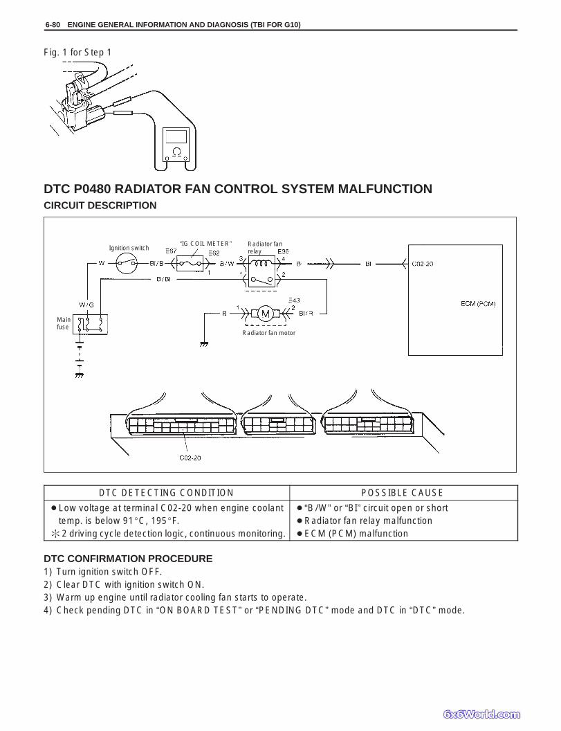
6-80 ENGINE GENERAL INFORMATION AND DIAGNOSIS (TBI FOR G10)
Fig. 1 for Step 1
Mainfuse
Ignition switch“IG COIL METER” Radiator fan
relay
Radiator fan motor
DTC P0480 RADIATOR FAN CONTROL SYSTEM MALFUNCTIONCIRCUIT DESCRIPTION
DTC DETECTING CONDITION POSSIBLE CAUSE
Low voltage at terminal C02-20 when engine coolanttemp. is below 91C, 195F.
2 driving cycle detection logic, continuous monitoring.
“B/W” or “BI” circuit open or short Radiator fan relay malfunction ECM (PCM) malfunction
DTC CONFIRMATION PROCEDURE1) Turn ignition switch OFF.2) Clear DTC with ignition switch ON.3) Warm up engine until radiator cooling fan starts to operate.4) Check pending DTC in “ON BOARD TEST” or “PENDING DTC” mode and DTC in “DTC” mode.

ENGINE GENERAL INFORMATION AND DIAGNOSIS (TBI FOR G10) 6-81
Fig. 1 for Step 2 Fig. 2 for Step 3
1. Radiator fan relay2. Relay box
INSPECTION
STEP ACTION YES NO
1 Was “ENGINE DIAG. FLOW TABLE” performed? Go to Step 2. Go to “ENGINE DIAG.FLOW TABLE”.
2 Check Radiator Cooling Fan Relay and Its Circuit.1) Turn ignition switch ON.2) Check for voltage at terminal C02-20 of ECM
(PCM) connector connected, under followingcondition. See Fig. 1.When engine coolant temp. is lower than96C, 205F and A/C switch turns OFF: 10 – 14 V
Is voltage as specified?
Intermittent trouble orfaulty ECM (PCM).Check for intermittentreferring to “Intermittentand Poor Connection”in Section 0A.
Go to Step 3.
3 Check Radiator Fan Control Relay.1) Turn ignition switch OFF and remove radiator
fan relay.2) Check for proper connection to the relay at
“B/W” and “Bl” wire terminals.3) If OK, then measure resistance between
terminals a and b. See Fig. 2.Is it 100 – 120 Ω?
“B/W” or “Bl” circuitopen or short.If wires and connectionsare OK, substitute aknown-good ECM (PCM)and recheck.
Replace radiator fanrelay.
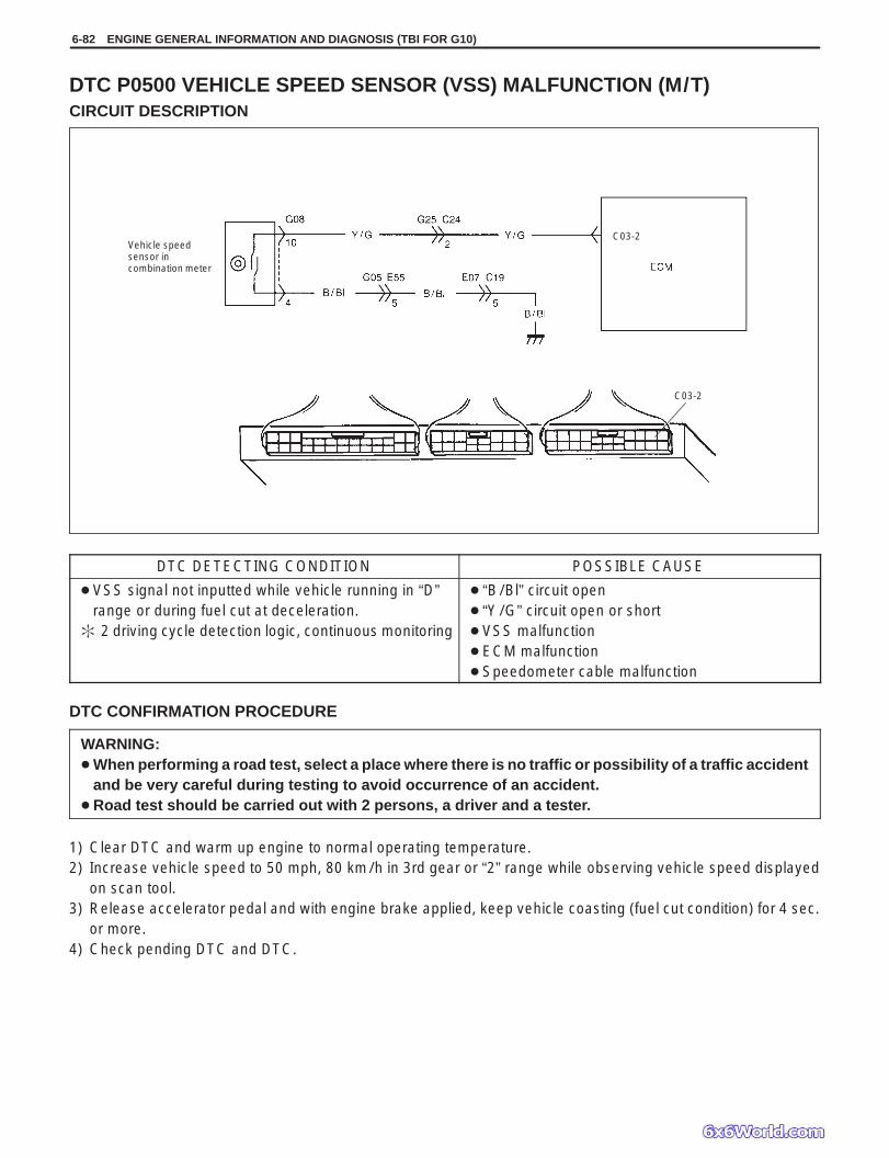
6-82 ENGINE GENERAL INFORMATION AND DIAGNOSIS (TBI FOR G10)
Vehicle speedsensor incombination meter
C03-2
C03-2
DTC P0500 VEHICLE SPEED SENSOR (VSS) MALFUNCTION (M/T)CIRCUIT DESCRIPTION
DTC DETECTING CONDITION POSSIBLE CAUSE
VSS signal not inputted while vehicle running in “D”range or during fuel cut at deceleration.
2 driving cycle detection logic, continuous monitoring
“B/Bl” circuit open “Y/G” circuit open or short VSS malfunction ECM malfunction Speedometer cable malfunction
DTC CONFIRMATION PROCEDURE
WARNING: When performing a road test, select a place where there is no traffic or possibility of a traffic accident
and be very careful during testing to avoid occurrence of an accident. Road test should be carried out with 2 persons, a driver and a tester.
1) Clear DTC and warm up engine to normal operating temperature.2) Increase vehicle speed to 50 mph, 80 km/h in 3rd gear or “2” range while observing vehicle speed displayed
on scan tool.3) Release accelerator pedal and with engine brake applied, keep vehicle coasting (fuel cut condition) for 4 sec.
or more.4) Check pending DTC and DTC.

ENGINE GENERAL INFORMATION AND DIAGNOSIS (TBI FOR G10) 6-83
Fig. 1 for Step 3 Fig. 2 for Step 4
C03-2
INSPECTION
STEP ACTION YES NO
1 Was “ENGINE DIAG. FLOW TABLE” performed? Go to Step 2. Go to “ENGINE DIAG.FLOW TABLE”.
2 Does speedometer indicate vehicle speed? Go to Step 3. Speedometer cabledisconnected orbroken.
3 Check VSS and Its Circuit.1) Disconnect ECM connector with ignition
switch OFF.2) Check for proper connection to ECM at
terminal C03-2.3) If OK, then connect ohmmeter between
terminal C03-2 of ECM connector and bodyground. See Fig. 1.
4) Hoist front end of vehicle and lock front righttire.
5) Turn front left tire slowly.Does ohmmeter indicator deflect between0 and ∞ a few times while tire is turned onerevolution?
Intermittent trouble or faulty ECM.Check for intermittentreferring to “Intermittentand Poor Connection”in Section 0A.
Go to Step 4.
4 Check VSS.1) Remove combination meter.2) Connect ohmmeter between “VSS” terminal
(No.10) and “GND” (No.4) terminal ofcombination meter and turn cable joint ofspeedometer with a screwdriver. Ohmmeterindicator should move back and forth between0 (zero) and ∞ (infinity) 4 times while cable jointis turned one full revolution. See Fig. 2.
Is it in good condition?
“Y/G” or “B/Bl” wireopen or short, or poorconnector connection.
Replace VSS.

6-84 ENGINE GENERAL INFORMATION AND DIAGNOSIS (TBI FOR G10)
Vehicle speed sensor (on A / T)
Countershaftgear
PCMC03-2
C03-13
Bl
P
C03-2
C03-13
DTC P0500 VEHICLE SPEED SENSOR (VSS) MALFUNCTION FOR A/TVEHICLE (A/T)
CIRCUIT DESCRIPTION – Refer to Section 6E1 for VSS operation.
DTC DETECTING CONDITION POSSIBLE CAUSE
While fuel is kept cut at lower than 4000 r/min forlonger than 4 sec.
VSS signal not inputted. 2 driving cycle detection logic, continuous
monitoring.
“BI” or “P” circuit open or short. Vehicle speed sensor malfunction. Foreign material being attached or sensor installed
improperly. Gear damaged.
DTC CONFIRMATION PROCEDURE
WARNING: When performing a road test, select a place where there is no traffic or possibility of a traffic accident
and be very careful during testing to avoid occurrence of an accident. Road test should be carried out with 2 persons, a driver and a tester, on a level road.
1) Turn ignition switch OFF and then ON.2) Clear DTC and warm up engine to normal operating temperature.3) Increase vehicle speed to 50 mph, 80 km/h in “2” range.4) Release accelerator pedal and with engine brake applied, keep vehicle coasting (fuel cut condition) for 4 sec.
or more.5) Stop vehicle and check DTC and pending DTC.

ENGINE GENERAL INFORMATION AND DIAGNOSIS (TBI FOR G10) 6-85
Fig. 1 for Step 2 Fig. 2 for Step 3
INSPECTION
STEP ACTION YES NO
1 Was “ENGINE DIAG. FLOW TABLE” performed? Go to Step 2. Go to “ENGINEDIAG. FLOWTABLE”.
2 Check VSS for Resistance.1) Disconnect VSS connection with ignition switch OFF.2) Check for proper connection to VSS at “Bl” and “P” wire
terminals.3) If OK, then check resistance of VSS. See Fig. 1.
Resistance between terminals : 100 – 300 ΩResistance between terminal and transmission : 1 MΩ or more
Are check result satisfactory?
Go to Step 3. Replace VSS.
3 Check Visually VSS and Counter Shaft Gear for theFollowing. See Fig. 2. No damage No foreign material attached Correct installationAre they in good condition?
“BI” or “P” wireopen or shorted toground or poorC03-2 or C03-13connection. Ifwires andconnections areOK, intermittenttrouble or faultyPCM. Check forintermittentreferring to“Intermittent andPoor Connection”in Section 0A.
Clean, repair orreplace.

Mainfuse
Main relay
Idle speedcontrol relay
To TP sensor
Idle speed control actuator
6-86 ENGINE GENERAL INFORMATION AND DIAGNOSIS (TBI FOR G10)
DTC P0505 IDLE CONTROL SYSTEM MALFUNCTIONCIRCUIT DESCRIPTION
DTC DETECTING CONDITION POSSIBLE CAUSE
DTC will set when A, B or C condition is met.A: Throttle opening change is small as compared with
electrically live time.B: Throttle valve opening is not within its target range
with CTP switch ON.C: Drive voltage exists though ECM (PCM) is not
outputting ISC drive command.
Malajusted accelerater cable Poor movement of throttle valve Closed throttle position switch malfunction Idle speed control actuator malfunction Idle speed control relay malfunction “Gr/B”, “Gr/Y”, “Gr”, “Gr/R”, “Gr/G”, “Lg” or “B/Bl”
circuit open or short Throttle position sensor malfunction ECM (PCM) malfunction
DTC CONFIRMATION PROCEDURE1) Turn ignition switch OFF.2) Clear DTC with ignition switch ON.3) Start cold engine.4) Run it idle for 5 min.5) Select “DTC” mode on scan tool and check DTC.
NOTE:If engine speed changes up and down when engine speed is increased by opening throttle valve morethan half but not changing its opening, it is possible that closed throttle position switch is malfunction-ing.

ENGINE GENERAL INFORMATION AND DIAGNOSIS (TBI FOR G10) 6-87
Fig. 1 for Step 3 Fig. 2 for Step 3 Fig. 3 for Step 3
1. ISCA relay2. Relay box
DTC P0505INSPECTION
STEP ACTION YES NO
1 Was “ENGINE DIAG. FLOW TABLE” performed? Go to Step 2. Go to “ENGINE DIAG.FLOW TABLE”.
2 Check Idle Control System.1) Connect SUZUKI scan tool to DLC with ignition
switch OFF, set parking brake and block drivewheels.
2) Warm up engine to normal operatingtemperature.
3) Clear DTC and select “MISC TEST” mode onSUZUKI scan tool.
Is it possible to control (increase and reduce)engine idle speed by using SUZUKI scan tool?
Check TP sensor (Go toDTC P0121 Flow Table)If TP sensor is OK,intermittent trouble orfaulty ECM (PCM).Check for intermittentreferring to “Intermittentand Poor Connection”in Section 0A.
Go to Step 3.
3 Check ISC Relay.1) Ignition switch OFF and remove ISC relay
(“ISCA”).2) Check for proper connection to ISC relay at
terminals 3 and 4.3) Check resistance between each two terminals.
Between terminals 1 and 2: InfinityBetween terminals 3 and 4: 100 – 120 Ω
4) Check that there is continuity betweenterminals 1 and 2 when battery is connected toterminals 3 and 4.
Is ISC relay in good condition?
Go to Step 4. Replace ISC relay.
4 Check Idle Speed Control Actuator.1) Check ISC actuator operation by referring to
ISC ACTUATOR INSPECTION in Section 6.Is it good condition?
Check “Gr/B”, “Gr/Y”,“Gr” and “Gr/R” circuitfor open and short.If wires and connectionsare OK, substitute aknown-good ECM(PCM) and recheck.
Replace throttle lowerbody with ISC actuator.
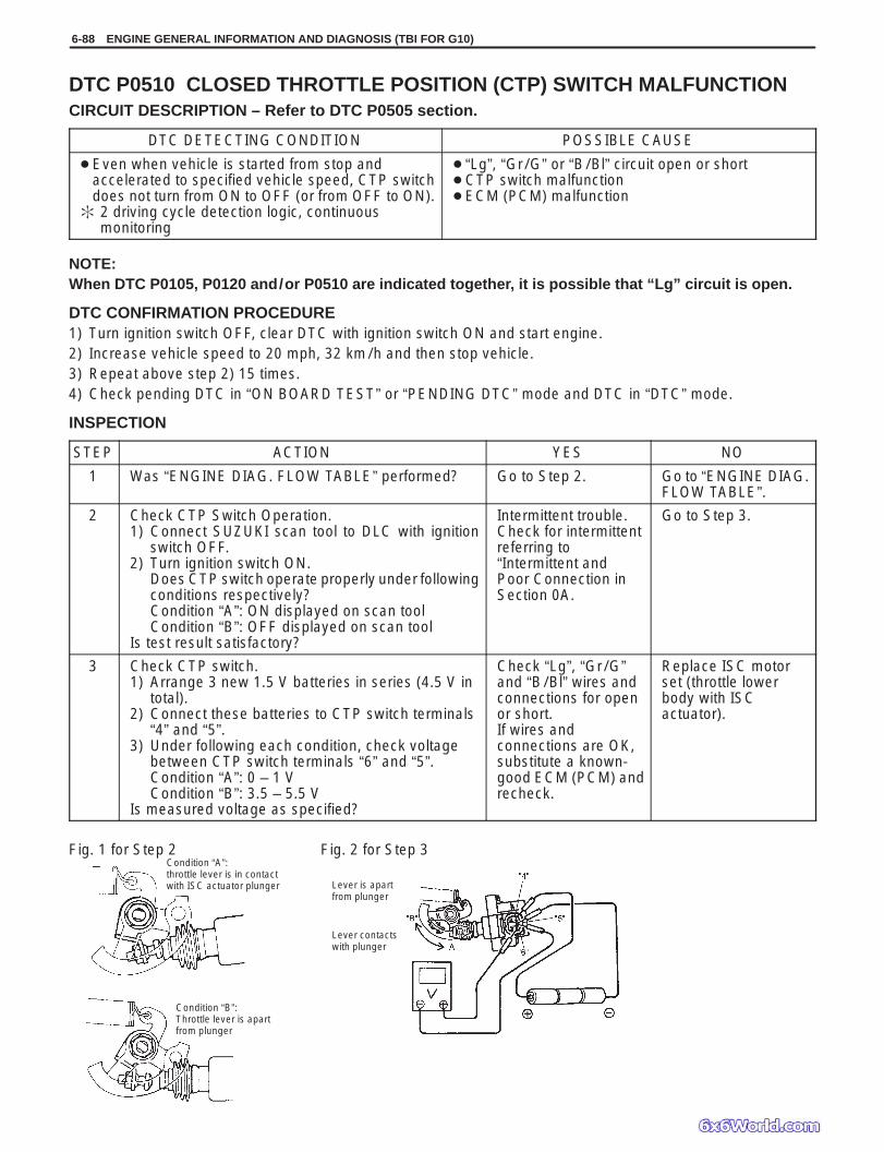
6-88 ENGINE GENERAL INFORMATION AND DIAGNOSIS (TBI FOR G10)
Fig. 1 for Step 2 Fig. 2 for Step 3
Lever is apartfrom plunger
Lever contactswith plunger
Condition “A”:throttle lever is in contactwith ISC actuator plunger
Condition “B”:Throttle lever is apartfrom plunger
DTC P0510 CLOSED THROTTLE POSITION (CTP) SWITCH MALFUNCTIONCIRCUIT DESCRIPTION – Refer to DTC P0505 section.
DTC DETECTING CONDITION POSSIBLE CAUSE
Even when vehicle is started from stop andaccelerated to specified vehicle speed, CTP switchdoes not turn from ON to OFF (or from OFF to ON).
2 driving cycle detection logic, continuousmonitoring
“Lg”, “Gr/G” or “B/Bl” circuit open or short CTP switch malfunction ECM (PCM) malfunction
NOTE:When DTC P0105, P0120 and/or P0510 are indicated together, it is possible that “Lg” circuit is open.
DTC CONFIRMATION PROCEDURE1) Turn ignition switch OFF, clear DTC with ignition switch ON and start engine.2) Increase vehicle speed to 20 mph, 32 km/h and then stop vehicle.3) Repeat above step 2) 15 times.4) Check pending DTC in “ON BOARD TEST” or “PENDING DTC” mode and DTC in “DTC” mode.
INSPECTION
STEP ACTION YES NO
1 Was “ENGINE DIAG. FLOW TABLE” performed? Go to Step 2. Go to “ENGINE DIAG.FLOW TABLE”.
2 Check CTP Switch Operation.1) Connect SUZUKI scan tool to DLC with ignition
switch OFF.2) Turn ignition switch ON.
Does CTP switch operate properly under followingconditions respectively?Condition “A”: ON displayed on scan toolCondition “B”: OFF displayed on scan tool
Is test result satisfactory?
Intermittent trouble.Check for intermittentreferring to“Intermittent andPoor Connection inSection 0A.
Go to Step 3.
3 Check CTP switch.1) Arrange 3 new 1.5 V batteries in series (4.5 V in
total).2) Connect these batteries to CTP switch terminals
“4” and “5”.3) Under following each condition, check voltage
between CTP switch terminals “6” and “5”.Condition “A”: 0 – 1 VCondition “B”: 3.5 – 5.5 V
Is measured voltage as specified?
Check “Lg”, “Gr/G”and “B/Bl” wires andconnections for openor short.If wires andconnections are OK,substitute a known-good ECM (PCM) andrecheck.
Replace ISC motorset (throttle lowerbody with ISCactuator).
ENGINE GENERAL INFORMATION AND DIAGNOSIS (TBI FOR G10) 6-89
DTC P0601 INTERNAL CONTROL MODULE MEMORY CHECK SUM ERROR
DTC DETECTING CONDITION POSSIBLE CAUSE
DTC P0601: Data write error (or check sum error)when written into ECM (PCM)
2 driving cycle detection logic, continuous monitoring.
ECM (PCM)
DTC CONFIRMATION PROCEDURE1) Turn ignition switch OFF.2) Clear DTC with ignition switch ON and then turn ignition switch OFF.3) Start engine and run it at idle if possible.4) Check pending DTC in “ON BOARD TEST” or “PENDING DTC” mode and DTC in “DTC” mode.
INSPECTIONSubstitute a known-good ECM (PCM) and recheck.
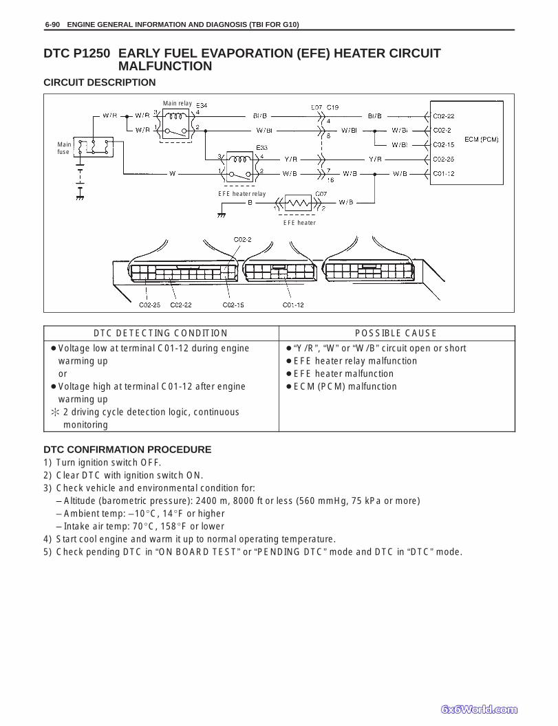
Mainfuse
Main relay
EFE heater
EFE heater relay
6-90 ENGINE GENERAL INFORMATION AND DIAGNOSIS (TBI FOR G10)
DTC P1250 EARLY FUEL EVAPORATION (EFE) HEATER CIRCUITMALFUNCTION
CIRCUIT DESCRIPTION
DTC DETECTING CONDITION POSSIBLE CAUSE
Voltage low at terminal C01-12 during enginewarming upor
Voltage high at terminal C01-12 after enginewarming up
2 driving cycle detection logic, continuousmonitoring
“Y/R”, “W” or “W/B” circuit open or short EFE heater relay malfunction EFE heater malfunction ECM (PCM) malfunction
DTC CONFIRMATION PROCEDURE1) Turn ignition switch OFF.2) Clear DTC with ignition switch ON.3) Check vehicle and environmental condition for:
– Altitude (barometric pressure): 2400 m, 8000 ft or less (560 mmHg, 75 kPa or more)– Ambient temp: –10C, 14F or higher– Intake air temp: 70C, 158F or lower
4) Start cool engine and warm it up to normal operating temperature.5) Check pending DTC in “ON BOARD TEST” or “PENDING DTC” mode and DTC in “DTC” mode.

ENGINE GENERAL INFORMATION AND DIAGNOSIS (TBI FOR G10) 6-91
1. Relay box2. “PTC”
INSPECTION
STEP ACTION YES NO
1 Was “ENGINE DIAG. FLOW TABLE” performed? Go to Step 2. Go to “ENGINE DIAG.FLOW TABLE”.
2 Check EFE Heater and Its Circuit.Check for voltage at terminal C01-12 of ECM (PCM)connector connected, under following eachcondition.During engine warming up (Coolant temp.:Below 80C, 176F, Engine speed: Over 750 r/min):Over 1.0 VAfter warming up: Below 1.0 VIs each voltage as specified?
Intermittent trouble.Check for intermittentreferring to“Intermittent and PoorConnection” inSection 0A.
Go to Step 3.
3 Check EFE Heater Relay.1) Turn OFF ignition switch and remove EFE heater
relay (“PTC”). See Fig. 2.2) Check for proper connection to relay at terminal
3 and 4. See Fig. 3.3) Check resistance between each two terminals.
Between terminals 1 and 2: InfinityBetween terminals 3 and 4: 100 – 120 Ω
4) Check that there is continuity between terminals1 and 2 when battery is connected to terminals3 and 4. See Fig. 4.
Is EFE heater relay in good condition?
Go to Step 4. Replace EFE heaterrelay.
4 Check EFE Heater and Its Circuit.1) Turn ignition switch OFF and disconnect ECM
(PCM) connectors.2) Check for proper connection to ECM (PCM) at
terminals C02-25 and C01-12.3) If OK, then measure resistance between terminal
C01-12 and ground.Is it 0.5 – 30 Ω at 20C (68F)?
“W”, “Y/R” or “W/B”circuit open or short.If wire andconnections are OK,substitute a known-good ECM (PCM) andrecheck.
“W/B” circuit open orshort.If wire andconnections are OK,replace EFE heater.
Fig 1. for Step 4 Fig. 2 for Step 3 Fig. 3 for Step 3
Fig. 4 for Step 3

6-92 ENGINE GENERAL INFORMATION AND DIAGNOSIS (TBI FOR G10)
Fig. 1 for Step 1
DTC P1450 BAROMETRIC PRESSURE SENSOR LOW/HIGH INPUTDTC P1451 BAROMETRIC PRESSURE SENSOR PERFORMANCE PROBLEMWIRING DIAGRAM/CIRCUIT DESCRIPTIONBarometric pressure sensor is installed in ECM (PCM).
DTC DETECTING CONDITION POSSIBLE CAUSE
DTC P1450: Barometric pressure: 136 kPa 1025 mmHg or higher, or
33 kPa 250 mmHg or lower
ECM (PCM) (barometric pressure sensor)malfunction
DTC P1451: Vehicle stopped. Engine cranking. Difference between barometric pressure and intake
manifold absolute pressure is 26 kPa, 200 mmHg or more. 2 driving cycle detection logic, monitoring once/1 driving.
Manifold absolute pressure sensor and itscircuit malfunction
ECM (PCM) (barometric pressure sensor)malfunction
DTC CONFIRMATION PROCEDURE1) Turn ignition switch OFF.2) Clear DTC with ignition switch ON.3) Turn ignition switch ON for 2 sec., crank engine for 2 sec. and run it at idle for 1 min.4) Check pending DTC in “ON BOARD TEST” or “PENDING DTC” mode and DTC in “DTC” mode.
INSPECTION
DTC P1450:Substitute a known-good ECM (PCM) and recheck.
DTC P1451:NOTE:Note that atmospheric pressure varies depending on weather conditions as well as altitude.Take that into consideration when performing these check.
STEP ACTION YES NO
1 1) Connect scan tool to DLC with ignition switchOFF.
2) Turn ignition switch ON and select “DATALIST” mode on scan tool.
3) Check manifold absolute pressure. See Fig. 1.Is it barometric pressure (approx. 100 kPa,760 mmHg) at sea level?
Substitute a known-good ECM (PCM) andrecheck.
Check intake manifoldpressure sensor and itscircuit.Go to P0105 DIAG.FLOW TABLE.
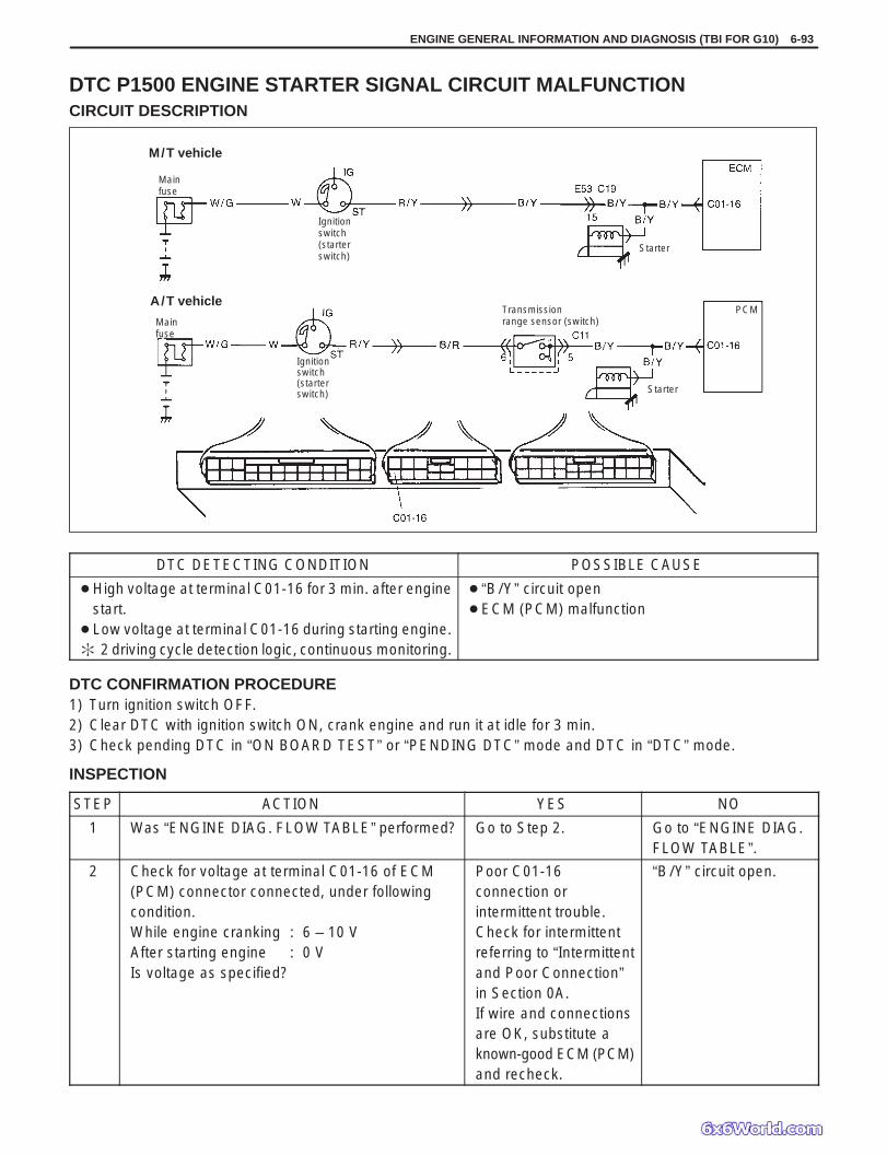
Mainfuse
M/T vehicle
Ignitionswitch(starterswitch)
Starter
A/T vehicle
Mainfuse
Ignitionswitch(starterswitch)
Transmissionrange sensor (switch)
Starter
PCM
ENGINE GENERAL INFORMATION AND DIAGNOSIS (TBI FOR G10) 6-93
DTC P1500 ENGINE STARTER SIGNAL CIRCUIT MALFUNCTIONCIRCUIT DESCRIPTION
DTC DETECTING CONDITION POSSIBLE CAUSE
High voltage at terminal C01-16 for 3 min. after enginestart.
Low voltage at terminal C01-16 during starting engine. 2 driving cycle detection logic, continuous monitoring.
“B/Y” circuit open ECM (PCM) malfunction
DTC CONFIRMATION PROCEDURE1) Turn ignition switch OFF.2) Clear DTC with ignition switch ON, crank engine and run it at idle for 3 min.3) Check pending DTC in “ON BOARD TEST” or “PENDING DTC” mode and DTC in “DTC” mode.
INSPECTION
STEP ACTION YES NO
1 Was “ENGINE DIAG. FLOW TABLE” performed? Go to Step 2. Go to “ENGINE DIAG.FLOW TABLE”.
2 Check for voltage at terminal C01-16 of ECM(PCM) connector connected, under followingcondition.While engine cranking : 6 – 10 VAfter starting engine : 0 VIs voltage as specified?
Poor C01-16connection orintermittent trouble.Check for intermittentreferring to “Intermittentand Poor Connection”in Section 0A.If wire and connectionsare OK, substitute aknown-good ECM (PCM)and recheck.
“B/Y” circuit open.

To DLC“DOME”
Mainfuse
6-94 ENGINE GENERAL INFORMATION AND DIAGNOSIS (TBI FOR G10)
DTC P1510 ECM (PCM) BACK-UP POWER SUPPLY MALFUNCTIONCIRCUIT DESCRIPTION
Battery voltage is supplied so that diagnostic trouble code memory, values for engine control learned by ECM(PCM), etc. are kept in ECM (PCM) even when the ignition switch is turned OFF.
DTC DETECTING CONDITION POSSIBLE CAUSE
Low voltage at terminal C02-14 after starting engine. “W” circuit open ECM (PCM) malfunction
DTC CONFIRMATION PROCEDURE1) Clear DTC, start engine and run it at idle for 1 min.2) Select “DTC” mode on scan tool and check DTC.
INSPECTION
STEP ACTION YES NO
1 Check for voltage at terminal C02-14 of ECM(PCM) connector connected, under eachcondition, ignition switch OFF and enginerunning.Is it 10 – 14 V at each condition?
Poor C02-14connection orintermittent trouble.Check for intermittentreferring to “Intermittentand Poor Connection”in Section 0A.If wire and connectionsare OK, substitute aknown- good ECM(PCM) and recheck.
“W” circuit open.

ENGINE GENERAL INFORMATION AND DIAGNOSIS (TBI FOR G10) 6-95
BLANK
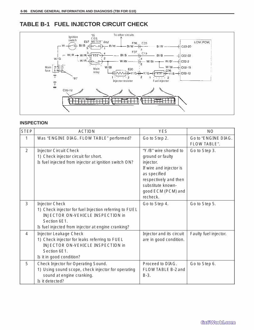
“IGCOILMETER”
Mainfuse
Ignitionswitch
Mainrelay
To other circuits
Injector resistor Fuel injector
6-96 ENGINE GENERAL INFORMATION AND DIAGNOSIS (TBI FOR G10)
TABLE B-1 FUEL INJECTOR CIRCUIT CHECK
INSPECTION
STEP ACTION YES NO
1 Was “ENGINE DIAG. FLOW TABLE” performed? Go to Step 2. Go to “ENGINE DIAG.FLOW TABLE”.
2 Injector Circuit Check1) Check injector circuit for short.Is fuel injected from injector at ignition switch ON?
“Y/B” wire shorted toground or faultyinjector.If wire and injector isas specifiedrespectively and thensubstitute known-good ECM (PCM) andrecheck.
Go to Step 3.
3 Injector Check1) Check injector for fuel Injection referring to FUEL
INJECTOR ON-VEHICLE INSPECTION inSection 6E1.
Is fuel injected from injector at engine cranking?
Go to Step 4. Go to Step 5.
4 Injector Leakage Check1) Check injector for leaks referring to FUEL
INJECTOR ON-VEHICLE INSPECTION inSection 6E1.
Is it in good condition?
Injector and its circuitare in good condition.
Faulty fuel injector.
5 Check Injector for Operating Sound.1) Using sound scope, check injector for operating
sound at engine cranking.Is it detected?
Proceed to DIAG.FLOW TABLE B-2 andB-3.
Go to Step 6.

ENGINE GENERAL INFORMATION AND DIAGNOSIS (TBI FOR G10) 6-97
STEP ACTION YES NO
6 Check Injector Resistor for Resistance.1) Disconnect resistor connector with ignition switch
OFF.2) Check for proper connection to resistor at each
terminals.3) If connection is OK, check resistance.Is resistance 1.9 – 2.1 Ω (at 20C, 68F)?
“W/Bl”, “Y/G” or “Y/B”wire open or poorC02-12 connection.If wires andconnections are OK,substitute a known-good ECM (PCM) andrecheck.
Replace resistor.

6-98 ENGINE GENERAL INFORMATION AND DIAGNOSIS (TBI FOR G10)
Mainfuse
Ignitionswitch
To other circuits
Mainrelay
Fuel pump relay Fuel pump
CAUTION: Check to make sure that connection ismade between correct terminals. Wrong connectioncan cause damage to ECM (PCM), wire harness, etc.
TABLE B-2 FUEL PUMP AND ITS CIRCUIT CHECK
INSPECTION
STEP ACTION YES NO
1 Was “ENGINE DIAG. FLOW TABLE” performed? Go to Step 2. Go to “ENGINEDIAG. FLOWTABLE”.
2 Check Fuel Pump Control System for Operation. See Fig. 1.Is fuel pump heard to operate for 2 sec. after ignition switchON?
Fuel pump circuitis in goodcondition.
Go to Step 3.
3 Check Fuel Pump for Operation.1) Remove fuel pump relay from relay box with ignition
switch OFF.2) Check for proper connection to relay at each terminals.3) If OK, using service wire, connect terminals E28-1 and
E28-2 of relay connector. See Fig. 2.
Is fuel pump heard to operate at ignition switch ON?
Go to Step 4. “P”, “B” or “W/Bl”circuit open or fuelpump malfunction.
4 Check Fuel Pump Relay for Operation.1) Check resistance between each two terminals of fuel
pump relay. See Fig.3.Between terminals “1” and “2”: InfinityBetween terminals “3” and “4”: 100 – 120 Ω
2) Check that there is continuity between terminals “1” and“2” when battery is connected to terminals “3” and “4”. SeeFig. 4.
Is fuel pump relay in good condition?
“P/W” circuit openor poor C02-21connection.If wire andconnection areOK, substitute aknown-good ECM(PCM) andrecheck.
Replace fuel pumprelay.
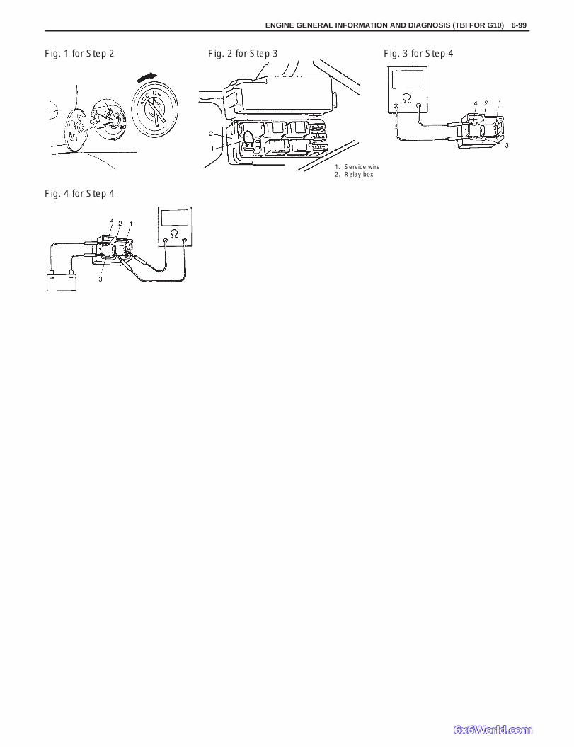
ENGINE GENERAL INFORMATION AND DIAGNOSIS (TBI FOR G10) 6-99
Fig. 1 for Step 2 Fig. 2 for Step 3
1. Service wire2. Relay box
Fig. 3 for Step 4
Fig. 4 for Step 4

1. Fuel pump2. Fuel filter3. Throttle body4. Fuel injector5. Fuel pressure regulator
6. Special tool(Fuel pressure gauge &3-way joint)
7. Fuel feed line8. Fuel return line
6-100 ENGINE GENERAL INFORMATION AND DIAGNOSIS (TBI FOR G10)
TABLE B-3 FUEL PRESSURE CHECK
INSPECTION
STEP ACTION YES NO
1 Check Fuel Pressure (Refer to Section 6E1 for details).1) Release fuel pressure from fuel feed line.2) Install fuel pressure gauge.3) Check fuel pressure by repeating ignition switch
ON and OFF. See Fig. 1.Is fuel pressure then 160 – 210 kPa (1.6 – 2.1 kg/cm2,22.7 – 29.9 psi)?
Go to Step 2. Go to Step 4.
2 Is 90 kPa (0.9 kg/cm2, 12.8 psi) or higher fuelpressure retained for 1 minute after fuel pump isstopped at Step 1?
Normal fuel pressure. Go to Step 3.
3 1) Start engine and warm it up to normal operatingtemperature.
2) Keep it running at specified idle speed.Is fuel pressure then within 90 – 140 kPa(0.9 – 1.4 kg/cm2, 12.8 – 20.0 psi)?
Normal fuel pressure. Clogged vacuumpassage for fuelpressure regulatoror
Faulty fuel pressureregulator.
4 Is there fuel leakage from fuel feed line hose, pipe ortheir joint?
Fuel leakage fromhose, pipe or joint.
Go to Step 10.
5 Was fuel pressure higher than specification in Step 1? Go to Step 6. Go to Step 7.
6 1) Disconnect fuel return hose from throttle body andconnect new return hose to it.
2) Insert the other end of new return hose intoapproved gasoline container.
3) Operate fuel pump.Is specified fuel pressure obtained then?
Restricted fuel returnhose or pipe.
Faulty fuel pressureregulator.
7 Was no fuel pressure supplied in Step 1? Go to Step 8. Go to Step 9.
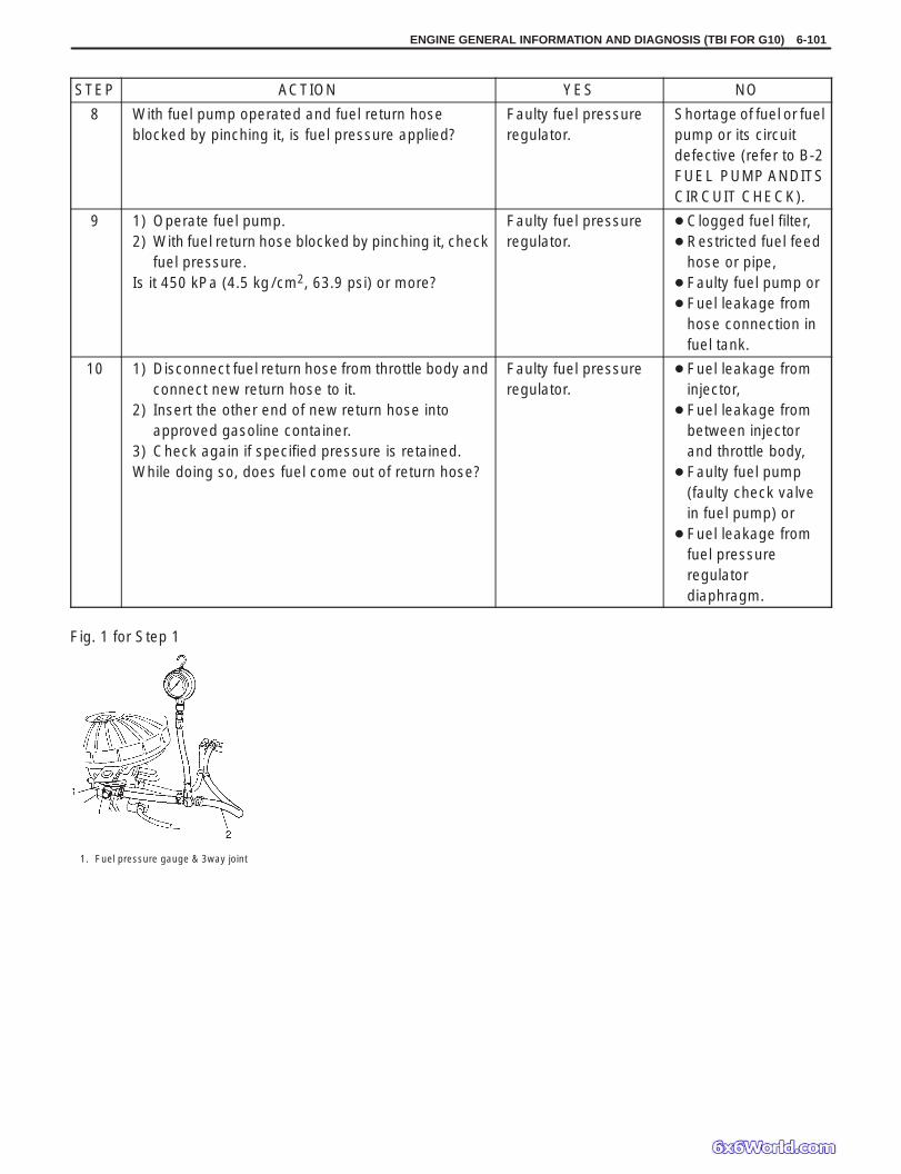
ENGINE GENERAL INFORMATION AND DIAGNOSIS (TBI FOR G10) 6-101
Fig. 1 for Step 1
1. Fuel pressure gauge & 3way joint
STEP ACTION YES NO
8 With fuel pump operated and fuel return hoseblocked by pinching it, is fuel pressure applied?
Faulty fuel pressureregulator.
Shortage of fuel or fuelpump or its circuitdefective (refer to B-2FUEL PUMP ANDITSCIRCUIT CHECK).
9 1) Operate fuel pump.2) With fuel return hose blocked by pinching it, check
fuel pressure.Is it 450 kPa (4.5 kg/cm2, 63.9 psi) or more?
Faulty fuel pressureregulator.
Clogged fuel filter, Restricted fuel feed
hose or pipe, Faulty fuel pump or Fuel leakage from
hose connection infuel tank.
10 1) Disconnect fuel return hose from throttle body andconnect new return hose to it.
2) Insert the other end of new return hose intoapproved gasoline container.
3) Check again if specified pressure is retained.While doing so, does fuel come out of return hose?
Faulty fuel pressureregulator.
Fuel leakage frominjector,
Fuel leakage frombetween injectorand throttle body,
Faulty fuel pump(faulty check valvein fuel pump) or
Fuel leakage fromfuel pressureregulatordiaphragm.

A / Camplifier
(A / C ON output signal)
(A / C input signal)
6-102 ENGINE GENERAL INFORMATION AND DIAGNOSIS (TBI FOR G10)
TABLE B-4 A/C SIGNAL CIRCUITS CHECK (VEHICLE WITH A/C)
INSPECTION
STEP ACTION YES NO
1 Check A/C (Input) Signal Circuit.1) Check voltage at terminal C03-19.
While engine running and A/C switchand/or heater blower switch OFF(A/C is not operating) : 10 – 14 VWhile engine running and both A/Cswitch and heater blower switch ON(A/C is operating) : About 0 V
Are check results as specified?
Go to Step 2. “Bl/R” wire open orshort.
Poor C03-19connection.
Poor A/C amplifiercoupler connectionor faulty A/Csystem.
2 Check A/C ON (Output) Signal Circuit.1) Check voltage at terminal C03-17.
While engine running and A/C switchand/or heater blower switch OFF(A/C is not operating) : About 0 VWhile engine running at idle speedand both A/C switch and heater blowerswitch ON (A/C is operating) : 10 – 14 V
Are check results as specified?
A/C control signalcircuits are in goodcondition.
“Lg/R” wire open orshort.
Poor performance ofECT sensor, TPsensor.
Engine start signalinputted or
Poor C03-17connection.
If none of the aboveexists, substitute aknown-good ECM(PCM) and recheck.
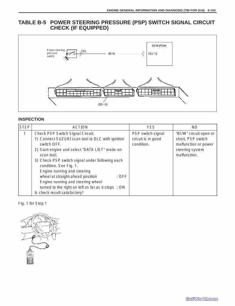
Power steeringpressureswitch
ENGINE GENERAL INFORMATION AND DIAGNOSIS (TBI FOR G10) 6-103
TABLE B-5 POWER STEERING PRESSURE (PSP) SWITCH SIGNAL CIRCUITCHECK (IF EQUIPPED)
INSPECTION
STEP ACTION YES NO
1 Check PSP Switch Signal Circuit.1) Connect SUZUKI scan tool to DLC with ignition
switch OFF.2) Start engine and select “DATA LIST” mode on
scan tool.3) Check PSP switch signal under following each
condition. See Fig. 1.Engine running and steeringwheel at straight-ahead position : OFFEngine running and steering wheelturned to the right on left as far as it stops : ON
Is check result satisfactory?
PSP switch signalcircuit is in goodcondition.
“Bl/W” circuit open orshort, PSP switchmalfunction or powersteering systemmalfunction.
Fig. 1 for Step 1

6-104 ENGINE GENERAL INFORMATION AND DIAGNOSIS (TBI FOR G10)
09931-76011SUZUKI scan tool (Tech 1 A) kit
1. Storage case2. Operator’s manual3. Tech 1 A4. DLC cable (14/26 pin,
09931-76040)5. Test lead/probe6. Power source cable7. DLC cable adaptor8. Self-test adaptor
-1. Pressure gauge09912-58441
-2. Pressure hose09912-58431
-3. 3-way joint & hose09912-58490
Mass storage cartridge09931-7603016/14 pin DLC cable
SPECIAL TOOL

ENGINE GENERAL INFORMATION AND DIAGNOSIS (TBI FOR G13) 6-1
SECTION 6
ENGINE GENERAL INFORMATIONAND DIAGNOSIS
(TBI FOR G13)NOTE:For the details of this section, refer to same section of the Service Manual mentioned in the FOREWORDof this manual.