Embed Size (px)
Citation preview

Engine DesignBen Rossiter

Introduction
For this section we will be considering the engine as two parts;
The lower part comprises of the cylinder block and the rotating assembly (Crankshaft, con-rods and pistons)
The upper part includes the cylinder head, the valves and the valve drive system.

The Lower part The function of the block and the rotating
assembly is to turn the pressure creating by burning the fuel, into a mechanical output.

Q. Which parts make up the rotating assembly?
The crankshaft, the connecting rods and the pistons
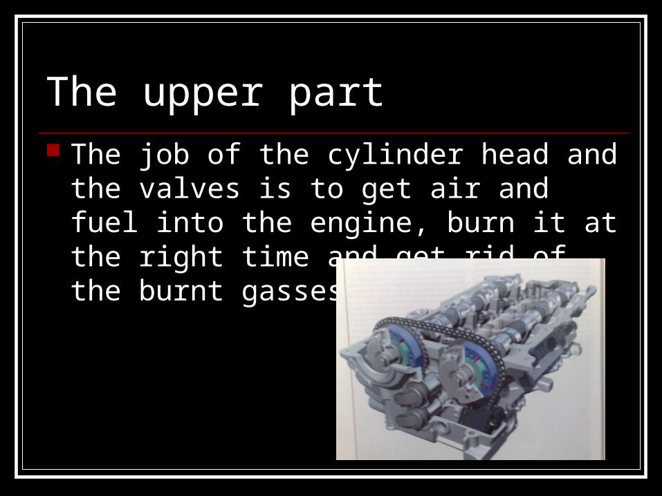
The upper part The job of the cylinder head and the valves
is to get air and fuel into the engine, burn it at the right time and get rid of the burnt gasses afterwards.

Mechanical output We previously mentioned Mechanical
output. This needs to be considered as both Torque and Power.
Torque“The average push provided by the engine.”It is the force applied at a given distance.It is dependant upon;1. The amount of pressure (BMEP) which pushes
the piston down during the power stroke2. The time for which the pressure is applied3. The area of the piston and the stroke4. The compression ratio*, valve timing and engine
speed.
*Hence why Diesels have more Torque generally.

Torque – Cont. When the engine is running
at high speed there is less time for pressure to develop.
Maximum torque occurs between 1/3 – 1/2
Of most engines maximum
safe speed.
Porsche 911 GT3 Torque curve

Power“The rate at which the engine does work.”
1. Work = Force x Distance 2. Power = (Force x Distance)/ Time
3. But Distance/ Time = Speed For a car, this correlates to:
Power = Force (Torque) x Speed (Engine speed)In real life car terms;
Max. Power vs. Aerodynamic Drag determines Max. SpeedTorque vs. Weight (influenced by gearing) determines the
acceleration

Power - cont So it is strange that most drivers value
acceleration over maximum speed, but they study power output figures over torque?!

Torque and Power The balance between torque and power is
important in the I.C. Engine, as it develops little torque when running slowly.
This must be considered throughout engine design.
Lets look at an example of this in practice....

Torque and Power example Consider an engine designed for good
torque output, with max. torque @ low speed i.e. 2500rpm
Compared to; A ‘peak power’ speed of 6000rpm with
max. safe speed of 7000rpm.

Q. How will the performance of the engines be different? The First example will be more flexible, pulling
more willingly from low speed and needing less gear changing.
Engines designed for high power will provide better performance (if the driver is willing to use the gearbox) keeping engine speed close to peak power.

Compromise We now see a need for compromise, in
order to achieve a specific output (Highly flexible, low speed torque or high performance with relatively weak low speed performance)
Or, of course, try to achieve the best of both worlds; The British imperial units were well balanced, their max. Torque in pounds feet being almost the same as the max. Power in bhp.

Adjusting the Balance The balance of power and torque is achieved by
increasing the maximum amount of power delivered by the engine (a lot easier than increasing the torque*)
This is because the power developed by an engine depends above all on the rate at which it can burn fuel, than in turn depending on how fast the air can be sucked in and expelled, which depends on the speed of the engine and the size of the ducts and valves.
*Except for what?
Engine Speed and its effect on power
In very round terms, Formula 1 racing teams recon than running an engine 1000rpm faster is worth another 50bhp.
(This of course put immense amounts of wear around the cylinders and piston rings and as such Formula 1 engines are only ever used twice before being rebuilt.)

Induction and exhaust High losses are incurred during the induction
of air and push out exhaust gasses. This sees a need for consideration of
thermodynamics, in terms of how the gasses will flow through the engine;
Inlet and exhaust manifolds, inlet and exhaust ports and combustion chambers must be considered during design.

The Combustion Chamber Windage losses occur through internal air
movements in the engine, other than those which take place inside the combustion chamber. For example;
Q. When the piston is descending during the induction stroke, what happens to the air beneath the piston?
A. It has to transfer to the space beneath one of the other pistons which is ascending on its power stroke.
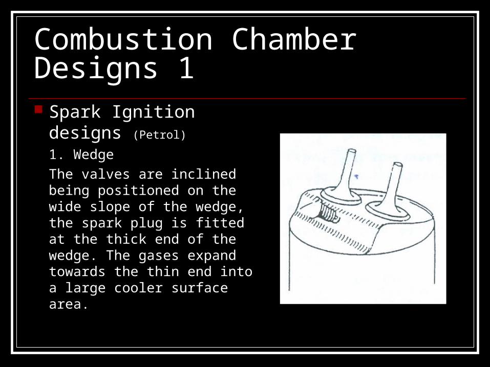
Combustion Chamber Designs 1 Spark Ignition designs
(Petrol)
1. Wedge
The valves are inclined being positioned on the wide slope of the wedge, the spark plug is fitted at the thick end of the wedge. The gases expand towards the thin end into a large cooler surface area.

Combustion Chambers Designs 22. Hemispherical
The valves are larger inclined and fitted across the engine. The plug is positioned as near centre as possible.
This shape provides maximum volume with minimum surface area

Combustion Chambers Designs 3 3. Bowl in Piston
The cylinder head is flat and the valves are positioned vertically.
The combustion chamber being formed in the piston crown, the shape being free from sharp edges.

Q. State Advantages of a hemispherical combustion chamber
The Hemispherical combustion chamber will give improved efficiency in the cylinder through gas-flow improvement.
Combustion radiates evenly, completely burning the air/fuel mixture.
Improved value dimensions, i.e. maximum volume with minimum surface area.
Performance Characteristics In order to obtain strong, low speed torque you need
a fast flow of air going into the combustion chamber. A narrow inlet port must therefore be used in order to
obtain maximum gas flow. By adding features which allow changing the size and shape
of the passages you can achieve ranging performance capabilities; some engines use 2 inlet valves per cylinder, with it being possible to shut off one of them at low speed, opening it only when the power requirement is high enough (High engine RPM.)

Performance Characteristics For maximum power, the engine must pass
as much air and fuel mixture as possible through itself in the shortest possible time.
Therefore the larger the valves and the deeper they open, the more mixture can enter the combustion chamber – as long as the rest of the intake system doesn’t restrict the flow!

Timing the Engine Engine timing can also have an effect upon
the induction and exhaust;“When the throttle is nearly closed, the induction stroke of the piston is not only sucking in air, but also reducing the air pressure in the whole of the inlet manifold, meaning the induction stroke itself consumes more power. The closer the throttle valve is to the inlet port, the more severe this effect becomes, which is the reason why modern petrol engines have seemingly complicated inlet manifolds with long air ducts.”

Diesel Efficiency “Diesels don't have throttle valves, so at
part-load their pumping losses are less.”This is one reason for a diesels higher efficiency.
Q. What is the other?
A. The higher compression ratio

The Upper Part of the engine The following slides will consider the major
aspects of the cylinder head.

The Cylinder Head The cylinder head bolts onto the top of the cylinder block where it
forms the top of the combustion chamber. In-line engines of light vehicles have just one cylinder head for all
the cylinders. Larger in-line engines can have 2 or more. V-type and horizontally-opposed engines have a separate cylinder
head for each bank of cylinders. Just as with engine blocks, cylinder heads can be made of cast
iron, or aluminium alloy. A head made of aluminium alloy is lighter than if it were made of
cast iron. Aluminium also conducts heat away more quickly than iron. So with an aluminium-alloy head, the heat of combustion can be conducted away into the coolant more quickly.
Manufacturing the head is similar to manufacturing the block. A casting mold is made. Sand cores are put in to form any hollow areas. Depending on the engine, these can be for coolant and lubricant passages, and inlet and exhaust ports.
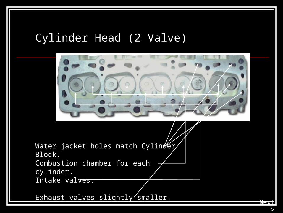
Cylinder Head (2 Valve)
Water jacket holes match Cylinder Block.
Combustion chamber for each cylinder.
Intake valves.
Exhaust valves slightly smaller.Next >
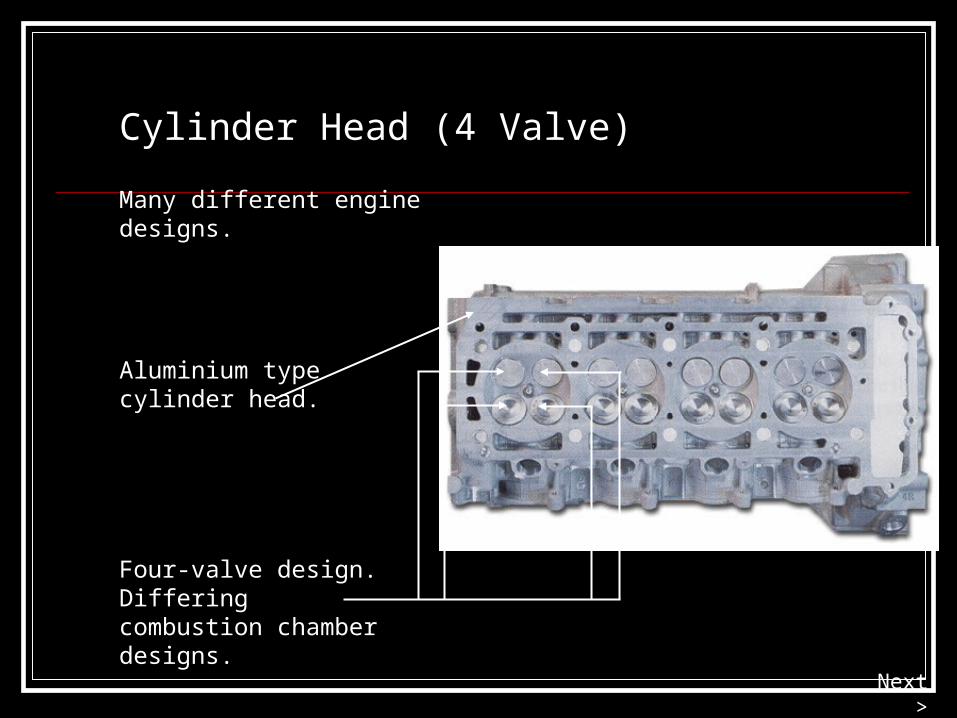
Cylinder Head (4 Valve)
Many different engine designs.
Aluminium typecylinder head.
Four-valve design. Differing combustion chamber designs.
Next >

Cylinder Head Components
Valve mounts.
Bare cylinder headholds many parts.
Valve openers.
Valves.
Cotters
Retainers
Seals
Springs
Bare cylinderhead
Valves
Rocker arms
Pivots
Push rods
Next >

Valves and Valve Seats

Valve seats in cylinder head In some cast-iron cylinder heads, the seats are
cut directly into the edge of the valve port. These valve seat areas are machined from the metal of the cylinder head. In some engines, the valve seat area is hardened during manufacture.
In others, hard metal valve seat inserts are pressed into the machined holes. Valve seat inserts are metal rings that match the shape of the valve. They are usually made of an iron alloy. They are used in aluminium cylinder heads to provide a sealing surface for seating the valve.

Valve Construction “Poppet” or “Mushroom”
The faces of the valve are ground at an angle of 45 degrees or 30 degrees. Some engines use 30 degrees or 45 degrees face angles for inlet valves, and 45 degrees for exhaust valves.
Valve seats are often ground to the same angle as the valve face, but they can differ. The difference is called an interference angle. An interference angle allows for a quick bedding-in of the valve face to the seat on new engines. It may also allow for slight changes in angle as a valve heats and expands.
The valve stem is precision ground to suit guide. (tight tolerance)
Seat angle
Next >
Changing Times (Fuel) Leaded fuels used to leave a deposit on the
valve that protected the valve seats. With unleaded petrol /gasoline, however this deposit doesn’t occur, and therefore all cast iron heads are now using unleaded fuel and have hardened valve seats.

Inlet Valve

Exhaust has higher temperatures.
Exhaust Valves
Sodium becomes liquid during operation and the heat transfer aides cooling.
Thicker stem.
Hollow-stem type.
Metallic sodium for cooling.
Thicker stem
Next >

Valve Seals
Keep oil out of combustion chamber.
Umbrella seals.
Spring shield.
O-ring seals.
Next >
Valve stem

Valve Oil Seals and Springs

Valve Springs and Valve Bounce• The springs usually have their coils closer at the bottom than the top; This makes different parts of the spring vibrate at different frequencies, and prevents wasteful valve spring vibration.
• Springs can also be made of wire with an especially shaped strong section that limits valve bounce.
• A duel coil spring assembly also helps to eliminate valve bounce; a condition where the springs resonate at high engine speed (causing them to open again after they have closed – losing pressure and therefore Torque.)
• Unless the valve is held on its seat, it also allows leakage from the combustion chamber. Carbon builds up on the valve stem.
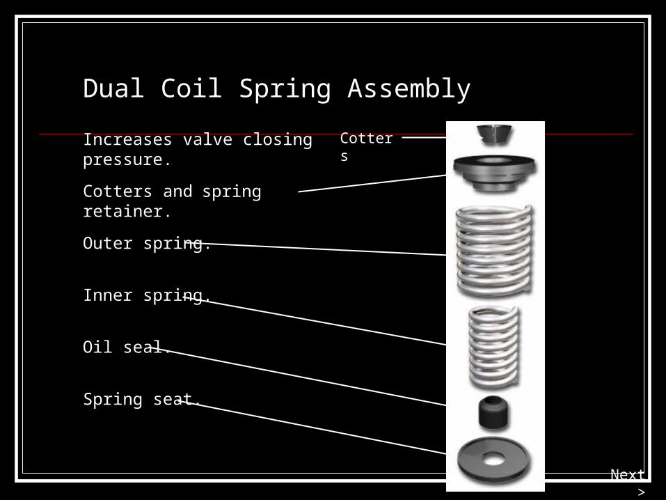
Dual Coil Spring Assembly
Increases valve closing pressure.
Cotters and spring retainer.
Outer spring.
Inner spring.
Oil seal.
Spring seat.
Cotters
Next >

Valve Guides
Integral valve guide is cheaper.
Clearance hole is machined in.
Valve seats may also be pressed-in type.
Pressed-in guide of cast iron or bronze.
Simplifies valve guide repair.
Seatinsert
Next >
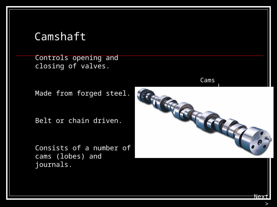
Camshaft
Made from forged steel.
Belt or chain driven.
Consists of a number of cams (lobes) and journals.
Controls opening and closing of valves.
Cams
Journals
Next >

The Camshaft

Camshaft and lobes

Cam Operation
Cams open and close valves.
As the camshaft rotates, campushes the valve open.
Intake valves on one side,exhaust on the other.
NoseDuration
Lift
Intake
Exhaust
Next >

A) The face
B) The nose
C) The beak
D) The eye
The diagram shows a cam. What is the pointed part called?
Question

Camshaft Locations
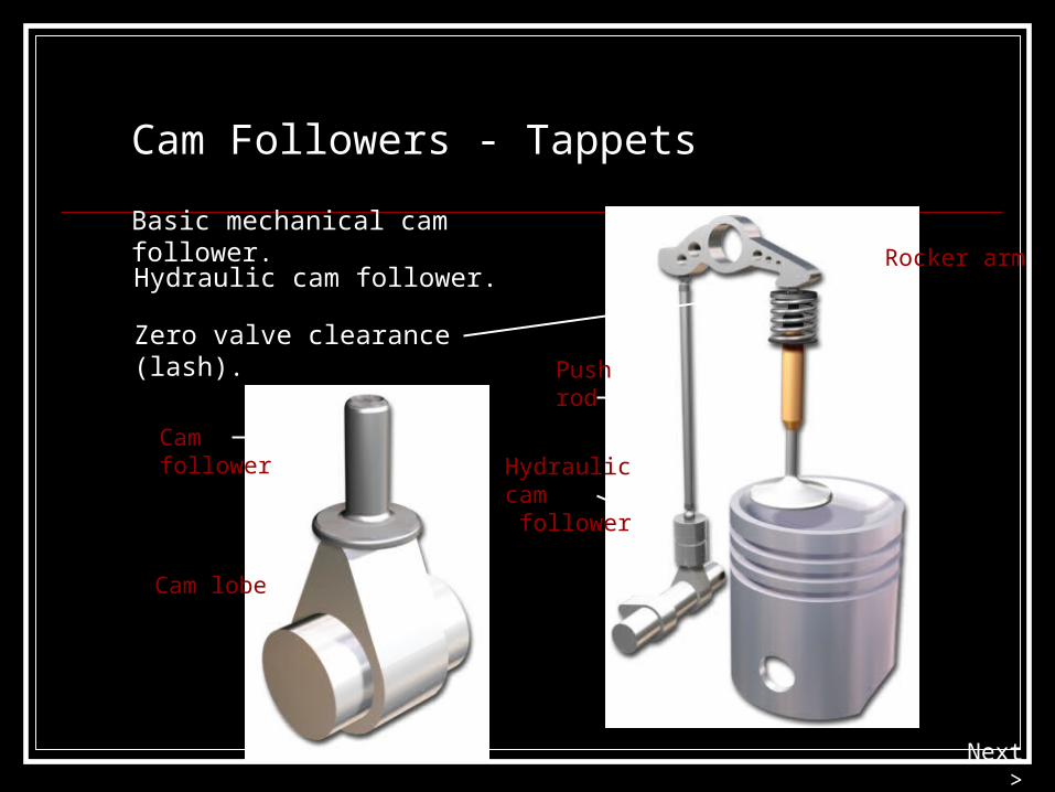
Cam Followers - Tappets
Basic mechanical cam follower.
Hydraulic cam follower.
Zero valve clearance (lash).
Cam follower
Cam lobe
Rocker arm
Push rod
Hydrauliccam follower
Next >

Solid follower.
Hydraulic follower.
Roller follower.
Cup type follower.
Cam Follower Types
Next >

Rocker Arms
Cast or pressed steel construction.
Transfers push-rod motion to valve.
Valve clearance is known as lash adjustment.
Next >

The Valve Train

Overhead Valve (OHV)
AKA Cam-in-Block.
Common in earlier engines.
Uses Valve follower, push rod and rocker arm.
Pushrod
Rocker arm
Valvefollower
Next >

OHV Gear Assembly1. Rocker shaft retaining
bolt
2. Pushrod
3. Lubrication passages
4. Exhaust valve assembly
5. Camshaft bearing journal
6. Camshaft lobe
7. Hydraulic tappet
8. Turbulence ramp
9. Inlet valve assembly
10.Rocker arm

Overhead Cam (OHC)
Camshaft in cylinder head.
Uses cup type follower.
May have separate camshafts for intake and exhaust valves.
Next >

SOHC Layout examples

DOHC Layout example
1. Idler pulley
2. Tensioning pulley
3. Drive belt
4. Inlet camshaft
5. Inlet valves
6. Exhaust camshaft
7. Exhaust valves

Valve Timing diagrams

Variable valve timing

Variable Cam Timing (VCT)
1. Camshaft Timing Pulley
2. Spring
3. Outer Helical Teeth
4. Adaptor with ring grooves
5. Oil supply to front chamber
6. Oil supply to rear chamber
7. Rear chamber
8. Front chamber
9. Blanking plug with seal
10. Inner Helical teeth