Embed Size (px)
Citation preview

ENGINE – 2ZR-FE ENGINEEG-28
�ENGINE CONTROL SYSTEM
1. General
The engine control system for the 2ZR-FE engine has following systems.
System Outline
SFI(Sequential MultiportFuel Injection)
� An L-type SFI system detects the intake air mass with a hot-wire type massair flow meter.
� The fuel injection system is a sequential multiport fuel injection system.
ETCS-i(Electronic ThrottleControlSystem-intelligent)[See page EG-44]
Optimally controls the throttle valve opening in accordance with the amountof accelerator pedal effort, the throttle valve opening control request from theECM, and the condition of the engine and the vehicle.
� A linkless-type is used, without an accelerator cable.� An accelerator pedal position sensor is provided on the accelerator pedal.� The non-contact type throttle position sensor and accelerator pedal position
sensor are used.
ESA(Electronic SparkAdvance)
Ignition timing is determined by the ECM based on signals from varioussensors. The ECM corrects ignition timing in response to engine knocking.
Dual VVT-i(Variable ValveTiming-intelligent)[See page EG-49]
Regulates operation of the intake and exhaust camshafts to ensure an optimalvalve timing in accordance with the engine condition.
Fuel Pump Control[See page EG-55]
� Fuel pump operation is controlled by signals from the ECM.� The fuel pump is stopped when the SRS airbag is deployed in a front or side
collision.
Heated OxygenSensor and Air-fuelRatio Sensor HeaterControl
Maintains the temperature of the heated oxygen sensor and air-fuel ratiosensor at an appropriate level to increase accuracy of detection of the oxygenconcentration in the exhaust gas.
Evaporative EmissionControl[See page EG-56]
The ECM controls the purge flow of evaporative emissions (HC) in thecanister in accordance with engine conditions.
Approximately five hours after the ignition switch has been turned OFF, theECM operates the canister pump module to detect any evaporative emissionleakage occurring in the EVAP (evaporative emission) control system throughchanges in the 0.02 in. leak pressure.
Engine ImmobilizerProhibits fuel delivery and ignition if an attempt is made to start the enginewith an invalid key.
Air ConditioningCut-off Control*
By turning the air conditioning compressor ON or OFF in accordance with theengine condition, drivability is maintained.
(Continued)*: Models with Air Conditioning System

ENGINE – 2ZR-FE ENGINE EG-29
System Outline
Cooling Fan Control[See page EG-68]
The cooling fan ECU steplessly controls the speed of the fans in accordancewith the engine coolant temperature, vehicle speed, engine speed, and airconditioning operating conditions. As a result, the cooling performance isimproved.
Starter Control(Cranking HoldFunction)[See page EG-70]
� Once the ignition switch is turned to the START position, this controlcontinues to operate the starter until the engine is started.*1
� Once the engine switch is pushed, this control continues to operate thestarter until the engine is started.*2
Diagnosis[See page EG-74]
When the ECM detects a malfunction, the ECM diagnoses and memorizes thefailed section.
Fail-safe[See page EG-74]
When the ECM detects a malfunction, the ECM stops or controls the engineaccording to the data already stored in memory.
*1: Models without Smart Key System*2: Models with Smart Key System

ENGINE – 2ZR-FE ENGINE
08MEG04Y
SENSORS
CRANKSHAFT POSITIONSENSOR
INTAKE CAMSHAFTPOSITION SENSOR
EXHAUST CAMSHAFTPOSITION SENSOR
MASS AIR FLOW METER
INTAKE AIRTEMPERATURE SENSOR
ENGINE COOLANTTEMPERATURE SENSOR
THROTTLE POSITIONSENSOR
ACCELERATOR PEDALPOSITION SENSOR
AIR-FUEL RATIO SENSOR(Bank 1, Sensor 1)
HEATED OXYGEN SENSOR(Bank 1, Sensor 2)
KNOCK SENSOR
CANISTER PUMP MODULE
CANISTER PRESSURESENSOR
TAILLIGHT RELAY
DEFOGGER RELAY
STOP LIGHT SWITCH
NE
G2
EV1
VG
THA
THW
VTA1VTA2
VPA1VPA2
A1A
OX1B
KNK1
PPMP
ELS1
ELS2
STPST1–
ECM
#10
#20
#30
#40
IGT1 – 4
IGF
OC1
OE1
M
HA1A
HT1B
FC
ACTUATORS
SFI
No. 1 FUEL INJECTOR
No. 2 FUEL INJECTOR
No. 3 FUEL INJECTOR
No. 4 FUEL INJECTOR
ESA
IGNITION COILwith IGNITER
SPARK PLUG
DUAL VVT-i
INTAKE CAMSHAFTTIMING OIL CONTROLVALVE
EXHAUST CAMSHAFTTIMING OIL CONTROLVALVE
ETCS-i
THROTTLE CONTROLMOTOR
AIR-FUEL RATIO SENSORAND HEATED OXYGENSENSOR HEATER CONTROL
Bank 1, Sensor 1
Bank 1, Sensor 2
FUEL PUMP CONTROL
CIRCUIT OPENINGRELAY
FUEL PUMP
EG-30
2. Construction
The configuration of the engine control system is as shown in the following chart.
(Continued)

ENGINE – 2ZR-FE ENGINE
08MEG05Y
CLUTCH SWITCH*1
PARK/NEUTRALPOSITION SWITCH*2
TRANSMISSION CONTROLSWITCH*2
BATTERY
EFI MAIN RELAY
IGNITION SWITCH*3
IG2 RELAY
CRUISE CONTROL SWITCH*4
TRANSPONDER KEY ECU*3
ID CODE BOX*5
SKID CONTROL ECU
No. 1 JUNCTIONCONNECTOR
No. 2 JUNCTIONCONNECTOR
AIR CONDITIONINGAMPLIFIER*6
AIRBAG SENSOR ASSEMBLY
DLC3
D
D, 2, L
3
BATT
+B
MREL
STSW
IGSW
CCS
IMI
IMO
CAN(V Bus)
TC
TACH
ECM
MPMP
PRG
RFC
STAR
ACCR
STA
STSW
ACCR
STAR
STA
SPD
W
VPMP
EVAPORATIVE EMISSIONCONTROL
LEAK DETECTIONPUMP
VENT VALVE
PURGE VSV
COOLING FAN CONTROL
COOLING FAN ECU
COOLING FAN MOTOR
STARTER CONTROL*3
STARTER RELAY
ACC CUT RELAY
STARTER SIGNAL
STARTER CONTROL*5
MAIN BODY ECU(Instrument PanelJunction Block)
ACC RELAY
ST CUT RELAY
PARK/NEUTRALPOSITION SWITCH
STARTER RELAY
COMBINATION METER
MIL
P, R, N
EG-31
*1: Manual Transaxle Models*2: Automatic Transaxle Models*3: Models without Smart Key System*4: Models with Cruise Control System*5: Models with Smart Key System*6: Models with Air Conditioning System

ENGINE – 2ZR-FE ENGINE
08SEG08Y
Skid ControlECU
Airbag SensorAssembly
Air ConditioningAmplifier*1
No. 1 JunctionConnector
No. 2 JunctionConnector
DLC3
Accelerator PedalPosition Sensor
CAN(V Bus)
ECM
Battery
Clutch Switch*4
Park/NeutralPosition Switch*5
Stop Light Switch
IG2 Relay
EFI Main Relay
CombinationMeter
Cruise ControlSwitch*6
Taillight Relay
Defogger Relay
Ignition Switch*2
Transponder KeyECU*2
ID Code Box*3
Cooling FanMotor
Cooling FanECU
Purge VSVCircuit Opening Relay
CanisterFilter
Canister Pump Module� Vent Valve� Leak Detection Pump� Canister Pressure Sensor
Fuel Pump
Intake CamshaftPosition Sensor
Ignition Coilwith Igniter
Exhaust CamshaftPosition Sensor
ThrottleControlMotor
ThrottlePositionSensor
FuelInjector
Mass Air Flow Meter(Built-in Intake Air Temperature Sensor)
Knock Sensor
*7 *8
Crankshaft Position Sensor
Air-fuel Ratio Sensor(Bank 1, Sensor 1)
Heated Oxygen Sensor(Bank 1, Sensor 2)
Engine CoolantTemperature Sensor
*1: Models with Air Conditioning System*3: Models with Smart Key System*5: Automatic Transaxle Models*7: Intake Camshaft Timing Oil Control Valve
*2: Models without Smart Key System*4: Manual Transaxle Models*6: Models with Cruise Control System*8: Exhaust Camshaft Timing Oil Control Valve
EG-32
3. Engine Control System Diagram

ENGINE – 2ZR-FE ENGINE
08MEG13Y
Accelerator Pedal Position Sensor
Canister Pump Module� Vent Valve� Leak Detection Pump� Canister Pressure Sensor
Fuel Pump AssemblyDLC3
Heated Oxygen Sensor(Bank 1, Sensor 2)
Mass Air Flow Meter(Built-in Intake AirTemperature Sensor)
ECM
Intake Camshaft TimingOil Control Valve
Exhaust Camshaft Timing Oil Control Valve
Ignition Coil with Igniter
Purge VSV
Exhaust Camshaft Position Sensor
Intake Camshaft Position Sensor
Air-fuel Ratio Sensor(Bank 1, Sensor 1)
Engine CoolantTemperature Sensor
Throttle Position Sensor
Knock Sensor
Crankshaft PositionSensor
Fuel Injector
EG-33
4. Layout of Main Components

ENGINE – 2ZR-FE ENGINEEG-34
5. Main Components of Engine Control System
General
The main components of the 2ZR-FE engine control system are as follows:
Components Outline Quantity Function
ECM 32-bit 1
The ECM optimally controls the SFI,ESA, and ISC to suit the operatingconditions of the engine in accordancewith the signals provided by the sensors.
Air-fuel Ratio Sensor(Bank 1, Sensor 1)
Type with Heater(Planar Type)
1
As with the heated oxygen sensor, thissensor detects the oxygen concentrationin the exhaust emission. However, itdetects the oxygen concentration in theexhaust emission linearly.
Engine CoolantTemperature Sensor
Thermistor Type 1This sensor detects the engine coolanttemperature by means of an internalthermistor.
Heated Oxygen Sensor(Bank 1, Sensor 2)
Type with Heater(Cup Type)
1
This sensor detects the oxygenconcentration in the exhaust emissionby measuring the electromotive forcewhich is generated in the sensor itself.
Mass Air Flow Meter Hot-wire Type 1This sensor has a built-in hot-wire todirectly detect the intake air mass.
Crankshaft PositionSensor (Rotor Teeth)
Pick-up Coil Type(36-2)
1This sensor detects the engine speed andperforms the cylinder identification.
Camshaft PositionSensor (Rotor Teeth)
MRE (MagneticResistance Element)
Type (3)2
This sensor performs the cylinderidentification.
Throttle PositionSensor
Non-contact Type 1This sensor detects the throttle valveopening angle.
Accelerator PedalPosition Sensor
Non-contact Type 1This sensor detects the amount of pedaleffort applied to the accelerator pedal.
Knock SensorBuilt-in Piezoelectric
Element Type(Flat Type)
1
This sensor detects an occurrence of theengine knocking indirectly from thevibration of the cylinder block causedby the occurrence of engine knocking.
Fuel Injector 12-hole Type 4
The fuel injector is anelectromagnetically-operated nozzlewhich injects fuel in accordance withthe signals from the ECM.

ENGINE – 2ZR-FE ENGINE
00REG21Y
Air-fuelRatio Sensor
A1A+(3.3 V)
A1A–
(2.9 V)
ECM
Air-fuel Ratio Sensor Circuit
HeatedOxygenSensor
OX1B
ECM
EX1B
Heated Oxygen Sensor
: Heated Oxygen Sensor: Air-fuel Ratio Sensor
4.2
Air-fuel Ratio Sensor DataDisplayed on Techstream
2.2
11(Rich) 14.7 19 (Lean)
0.1
Heated OxygenSensor Output (V)
1
Air-fuel RatioD13N11
EG-35
Air-fuel Ratio Sensor and Heated Oxygen Sensor
1) General
� The air-fuel ratio sensor and heated oxygen sensor differ in output characteristics.
� Approximately 0.4V is constantly applied to the air-fuel ratio sensor, which outputs an amperage thatvaries in accordance with the oxygen concentration in the exhaust emission. The ECM converts thechanges in the output amperage into voltage in order to linearly detect the present air-fuel ratio. Theair-fuel ratio sensor data is read out by the Techstream.
� The output voltage of the heated oxygen sensor changes in accordance with the oxygen concentrationin the exhaust emission. The ECM uses this output voltage to determine whether the present air-fuelratio is richer or leaner than the stoichiometric air-fuel ratio.

ENGINE – 2ZR-FE ENGINE
047EG68Y
Alumina
Atmosphere
Heater
Sensor Element (Zirconia)
PlatinumElectrode
Alumina
Dilation Layer
Planar Type Air-fuel Ratio Sensor
HeaterAtmosphere
Sensor Element(Zirconia)
Cup Type Heated Oxygen Sensor
PlatinumElectrode
01YEG10Y
Hot-wire Element
TemperatureSensing Element
Air FlowIntake Air Temperature Sensor
EG-36
2) Construction
� The basic construction of the air-fuel ratio sensor and heated oxygen sensor is the same. However, theyare divided into the cup type and the planar type, according to the different types of heater constructionthat are used.
� The cup type sensor contains a sensor element that surrounds a heater.
� The planar type sensor uses alumina, which excels in heat conductivity and insulation, to integrate asensor element with a heater, thus realizing the excellent warm-up performance of the sensor.
� Warm-up Specification �
Sensor Type Planar Type Cup Type
Warm-up Time Approx. 10 sec. Approx. 30 sec.
Mass Air Flow Meter
� This compact and lightweight mass air flow meter, which is a plug-in type, allows a portion of the intakeair to flow through the detection area. By directly measuring the mass and the flow rate of the intake air,the detection precision is improved and the intake air resistance has been reduced.
� This air flow meter has a built-in intake air temperature sensor.

ENGINE – 2ZR-FE ENGINE
04FEG64Y04FEG63Y
CrankshaftPositionSensor
Timing Rotor
Intake CamshaftPosition Sensor
Exhaust CamshaftPosition Sensor
Timing Rotors
08MEG14Y
720° CA
180° CA 180° CA 180° CA
360° CA 360° CA
5 V
0 V
0 V
2 Teeth Missing
EG-37
Crankshaft and Camshaft Position Sensors
1) General
� The pick-up coil type crankshaft position sensor is used. The timing rotor of the crankshaft consistsof 34 teeth, with 2 teeth missing. The crankshaft position sensor outputs the crankshaft rotation signalsevery 10�, and the missing teeth are used to determine the top-dead-center.
� The MRE (Magnetic Resistance Element) type intake and exhaust camshaft position sensors are used.To detect the camshaft position, each timing rotor on the intake and exhaust camshafts is used togenerate 3 (3 Hi Output, 3 Lo Output) pulses for every 2 revolutions of the crankshaft.
� Sensor Output Waveforms �

ENGINE – 2ZR-FE ENGINE
04FEG96Y
Timing Rotor
Intake CamshaftPosition Sensor
VCV1
G2+
G2–ECM
232CH41
EngineSpeed
SensorOutput
MRE Type
Digital Output
EngineSpeed
SensorOutput
No Detecting
Analog Output
Pick-up Coil Type
EG-38
2) MRE Type Camshaft Position Sensor
� The MRE type camshaft position sensor consists of an MRE, a magnet and a sensor. The direction ofthe magnetic field changes due to the different shapes (protruded and non-protruded portions) of thetiming rotor, which passes by the sensor. As a result, the resistance of the MRE changes, and the outputvoltage to the ECM changes to Hi or Lo. The ECM detects the camshaft position based on this outputvoltage.
� The differences between the MRE type camshaft position sensor and the pick-up coil camshaftposition sensor used on the conventional model are as follows.
ItemSensor Type
MRE Pick-up Coil
Signal OutputConstant digital output starts fromlow engine speeds.
Analog output changes withthe engine speed.
Camshaft Position Detection
Detection is made by comparingthe NE signals with the Hi/Looutput switch timing due to theprotruded/non-protrudedportions of the timing rotor, ormade based on the number of theinput NE signals during Hi/Looutputs.
Detection is made bycomparing the NE signalswith the change of waveformthat is output when theprotruded portion of thetiming rotor passes.
� Wiring Diagram �
� MRE Type and Pick-up Coil Type Output Waveform Image Comparison �

ENGINE – 2ZR-FE ENGINE
04FEG78Y
082EG14Y230LX12
Throttle Body Throttle PositionSensor Portion
A View from A
MagneticYoke
Hall IC
MagneticYoke
Cross Section
Throttle PositionSensor
Magnetic Yoke
Magnetic Yoke
VTA1
ETA
VCTA
VTA2
ECM
HallIC
HallIC
V
OutputVoltage
0
VTA2
VTA1
Fully Close Fully Open
Throttle Valve Opening Angle
Service TipThe inspection method differs from the conventional contact type throttle position sensor becausethis non-contact type sensor uses a Hall IC. For details, refer to the 2009 Corolla Repair Manual(Pub. No. RM08M0U).
EG-39
Throttle Position Sensor
The non-contact type throttle position sensor is used. This sensor uses a Hall IC, which is mounted on thethrottle body.
� The Hall IC is surrounded by a magnetic yoke. The Hall IC converts the changes that occur in themagnetic flux at that time into electrical signals and outputs it as a throttle valve effort to the ECM.
� The Hall IC contains circuits for the main and sub signals. It converts the throttle valve opening anglesinto electric signals with two differing characteristics and outputs them to the ECM.

ENGINE – 2ZR-FE ENGINE
04FEG94Y
082EG12Y228TU24
A
A
Internal Construction
Magnetic Yoke
Accelerator PedalArm
Magnetic Yoke
Hall IC
A – A Cross Section
Accelerator PedalPosition Sensor
Magnetic Yoke
HallIC
Magnetic Yoke
VPA
EPA
VCPA
VPA2
EPA2
HallIC
VCP2
ECM
V
OutputVoltage
5
0
VPA2
VPA
FullyClose
FullyOpen
Accelerator Pedal Depressed Angle
Service TipThe inspection method differs from the conventional contact type accelerator pedal positionsensor because this non-contact type sensor uses a Hall IC.For details, refer to the 2009 Corolla Repair Manual (Pub. No. RM08M0U).
EG-40
Accelerator Pedal Position Sensor
The non-contact type accelerator pedal position sensor uses a Hall IC.
� The magnetic yoke that is mounted at the accelerator pedal arm rotates around the Hall IC in accordancewith the amount of effort that is applied to the accelerator pedal. The Hall IC converts the changes in themagnetic flux that occur at that time into electrical signals, and outputs them as accelerator pedal effortto the ECM.
� The Hall IC contains circuits for the main and sub signals. It converts the accelerator pedal depressedangles into electric signals with two differing characteristics and outputs them to the ECM.
� TMC Models �

ENGINE – 2ZR-FE ENGINE
08SEG06Y
082EG12Y285EG72
Sensor Housing
Hall IC
Accelerator Pedal Arm
Magnetic Yoke
Hall ICVCPA EPA VPA
Hall IC
Magnetic Yoke
VCP2
EPA2
VPA2
ECM
V5
Output Voltage
0
VPA2
VPA
FullyClose
FullyOpen
Accelerator Pedal Depressed Angle
Service Tip
The inspection method differs from the conventional contact type accelerator pedal positionsensor because this non-contact type sensor uses a Hall IC.For details, refer to the 2009 Corolla Repair Manual (Pub. No. RM08M0U).
EG-41
� TMMC & NUMMI Models �

ENGINE – 2ZR-FE ENGINE
214CE04
: Conventional Type
: Flat Type
(V)
Voltage
A
B
A: Detection Band of Conventional Type
B: Detection Band of Flat Type
Frequency (Hz)Characteristic of Knock Sensor
214CE02214CE01
Steel Weight
Insulator
Piezoelectric Element
Open/Short Circuit Detection Resistor
Flat Type Knock Sensor(Non-resonant Type)
Piezoelectric Element
Vibration Plate
Conventional Type Knock Sensor(Resonant Type)
EG-42
Knock Sensor (Flat Type)
1) General
In the conventional type knock sensor (resonant type), a vibration plate which has the same resonancepoint as the knocking frequency of the engine is built in and can detect the vibration in this frequencyband.On the other hand, a flat type knock sensor (non-resonant type) has the ability to detect vibration in awider frequency band from about 6 kHz to 15 kHz, and has the following features.
� The engine knocking frequency will change a bit depending on the engine speed. The flat type knocksensor can detect the vibration even when the engine knocking frequency is changed. Thus thevibration detection ability is increased compared to the conventional type knock sensor, and a moreprecise ignition timing control is possible.
2) Construction
� The flat type knock sensor is installed on the engine through the stud bolt installed on the cylinderblock. For this reason, a hole for the stud bolt is running through the center of the sensor.
� Inside of the sensor, a steel weight is located on the upper portion and a piezoelectric element is locatedunder the weight through the insulator.
� The open/short circuit detection resistor is integrated.

ENGINE – 2ZR-FE ENGINE
214CE08
Steel Weight
Inertia
Piezoelectric Element
214CE06
Knock Sensor
Piezoelectric Element
200 kΩ
Open/Short Circuit Detection Resistor
KNK1
EKNK
ECM
5 V
150 kΩ
IC
Service Tip
� In accordance with the adoption of an open/short circuit detection resistor, the inspectionmethod for the sensor has been changed. For details, refer to the 2009 Corolla Repair Manual(Pub. No. RM08M0U).
� To prevent the water accumulation in the connecter, make sure to install the flat type knocksensor in the position as shown in the following illustration.
04FEG70Y
Knock Sensor
10� 10�
EG-43
3) Operation
The knocking vibration is transmitted to thesteel weight and its inertia applies pressure tothe piezoelectric element. The actiongenerates electromotive force.
4) Open/Short Circuit Detection Resistor
While the ignition is ON, the open/short circuit detection resistor in the knock sensor and the resistorin the ECM keep constant the voltage at the terminal KNK1 of engine.An IC (Integrated Circuit) in the ECM is always monitoring the voltage of the terminal KNK1. If theopen/short circuit occurs between the knock sensor and the ECM, the voltage of the terminal KNK1 willchange and the ECM detects the open/short circuit and stores DTC (Diagnostic Trouble Code).

ENGINE – 2ZR-FE ENGINE
01ZEG05Y
Accelerator Pedal Position Sensor
Throttle Valve Throttle Position Sensor
Throttle Control Motor
Mass Air Flow Meter
Cruise Control Switch*
Skid Control ECU
CAN (V Bus)
ECMIgnition Coil
Fuel Injector
EG-44
6. ETCS-i (Electronic Throttle Control System-intelligent)
General
� The ETCS-i is used, providing excellent throttle control in all the operating ranges.
� The accelerator cable has been discontinued, and an accelerator pedal position sensor has been providedon the accelerator pedal.
� In the conventional throttle body, the throttle valve opening angle is determined invariably by the amountof the accelerator pedal effort. In contrast, the ETCS-i uses the ECM to calculate the optimal throttlevalve opening angle that is appropriate for the respective driving condition and uses a throttle controlmotor to control the opening angle.
� The ETCS-i controls the ISC (Idle Speed Control) system, the TRAC (Traction Control), VSC (VehicleStability Control) system and cruise control system*.
� In case of an abnormal condition, this system switches to the limp mode.
� System Diagram �
*: Models with Cruise Control System

ENGINE – 2ZR-FE ENGINE
00REG05Y
Throttle Body
Throttle Control Motor
Throttle Position Sensor Portion
A
Reduction Gears
View from A
Throttle Valve
Magnetic Yoke
Hall IC (for Throttle Position Sensor)
Throttle Control Motor
Cross Section
EG-45
Construction
1) Throttle Position Sensor
The throttle position sensor is mounted on the throttle body to detect the opening angle of the throttlevalve.
2) Throttle Control Motor
A DC motor with excellent response and minimal power consumption is used for the throttle controlmotor. The ECM performs the duty cycle control of the direction and the amperage of the current thatflows to the throttle control motor in order to regulate the opening angle of the throttle valve.
Operation
1) General
The ECM drives the throttle control motor by determining the target throttle valve opening angle inaccordance with the respective operating condition.
� Non-linear Control
� Idle Speed Control
� TRAC Throttle Control
� VSC Coordination Control
� Cruise Control*
*: Models with Cruise Control System

ENGINE – 2ZR-FE ENGINE
005EG13Y
: With Control: Without Control
Vehicle’s Longitudinal G
Throttle Valve Opening Angle
Accelerator Pedal Depressed Angle
�
0
�
0
�
0Time �
EG-46
2) Non-linear Control
The ECM controls the throttle valve to an optimal opening angle that is appropriate for the drivingcondition such as the amount of the accelerator pedal effort and the engine speed in order to realizeexcellent throttle control and comfort in all operating ranges.
� Control Examples During Acceleration and Deceleration �
3) Idle Speed Control
The ECM controls the throttle valve in order to constantly maintain an ideal idle speed.
4) TRAC Throttle Control
As part of TRAC system, the throttle valve is closed by a request signal from the skid control ECU if anexcessive amount of slippage is created at a driving wheel, thus it facilitates the vehicle in ensuringstability and driving force.
5) VSC Coordination Control
In order to bring the effectiveness of the VSC system control into full play, the throttle valve openingangle is controlled by effecting a coordination control with the skid control ECU.
6) Cruise Control*
An ECM with an integrated cruise control ECU directly actuates the throttle valve for operation of thecruise control.
*: Models with Cruise Control System

ENGINE – 2ZR-FE ENGINE
199EG45
ECM
Accelerator Pedal Position Sensor
MainSub
Accelerator Pedal
Open
MainSub
Throttle Valve Return Spring
Throttle Control Motor
Throttle Body
Throttle Position Sensor
199EG46
ECM
Accelerator Pedal Position Sensor
MainSub
Accelerator Pedal
Close by Return Spring
MainSub
Throttle Position Sensor
Throttle Valve Return Spring
Throttle Control Motor
Throttle Body
EG-47
Fail-safe of Accelerator Pedal Position Sensor
� The accelerator pedal position sensor is comprised of two (main, sub) sensor circuits. If a malfunctionoccurs in either one of the sensor circuits, the ECM detects the abnormal signal by voltage differencebetween these two sensor circuits and switches to the limp mode. In the limp mode, the remaining circuitis used to calculate the accelerator pedal depressed angle, in order to operate the vehicle under limp modecontrol.
� If both circuits have a malfunction, the ECM detects the abnormal signal by voltage from these twosensor circuits and discontinues the throttle control. At this time, the vehicle can be driven within itsidling range.

ENGINE – 2ZR-FE ENGINE
199EG47
Fuel Injectors ECM Ignition Coil
Accelerator Pedal Position Sensor
MainSub
Accelerator Pedal
Return to Prescribed Angle
MainSub
Throttle Position Sensor
Throttle Valve Return Spring
Throttle Control Motor
Throttle Body
EG-48
Fail-safe of Throttle Position Sensor
� The throttle position sensor is comprised of two (main, sub) sensor circuits. If a malfunction occurs ineither one or both of the sensor circuits, the ECM detects the abnormal signal by voltage differencebetween these two sensor circuits, cuts off the current to the throttle control motor, and switches to thelimp mode. Then, the force of the return spring causes the throttle valve to return and stay at the prescribedopening angle. At this time, the vehicle can be driven in the limp mode while the engine output isregulated through the control of the fuel injection (intermittent fuel-cut) and ignition timing inaccordance with the accelerator opening.
� The same control as above is effected if the ECM detects a malfunction in the throttle control motorsystem.

ENGINE – 2ZR-FE ENGINE
04FEG114Y
Exhaust Camshaft Timing OCV*Intake Camshaft Timing OCV*
Exhaust Camshaft Position Sensor
Intake Camshaft Position Sensor
Engine Coolant Temperature Sensor
ECM
� Mass Air Flow Meter
� Throttle Position Sensor
Crankshaft Position Sensor
*: Oil Control Valve
221EG16
ECM
Crankshaft Position Sensor
Mass Air Flow Meter
Throttle Position Sensor
Engine Coolant Temp. Sensor
Camshaft Position Sensors
Vehicle Speed Signal
Target Valve Timing
Feedback
Correction
Actual Valve Timing
Duty CycleControl
Camshaft Timing Oil Control Valves
EG-49
7. Dual VVT-i (Variable Valve Timing-intelligent) System
General
� The Dual VVT-i system is designed to control the intake and exhaust camshafts within a range of 55�and 40� respectively (of Crankshaft Angle) to provide valve timing that is optimally suited to the enginecondition. This improves torque in all the speed ranges as well as increasing fuel economy, and reducingexhaust emissions.
� Using the engine speed, intake air mass, throttle position and engine coolant temperature, the ECM cancalculate optimal valve timing for each driving condition and controls the camshaft timing oil controlvalve. In addition, the ECM uses signals from the camshaft position sensor and the crankshaft positionsensor to detect the actual valve timing, thus providing feedback control to achieve the target valvetiming.

ENGINE – 2ZR-FE ENGINE
281EG42
281EG43
281EG44
281EG45
281EG46
281EG42
281EG42
TDC
BDC
EX IN
EX IN
EX IN
EX IN
EX IN
EX IN
EX IN
Most Retarded
To Retarded Side
To Advanced Side
To Advanced Side
To Retarded Side
Most Retarded
EG-50
Effectiveness of Dual VVT-i System
Operation State Objective Effect
During IdlingEliminating overlap toreduce blow back to theintake side
� Stabilized idle speed� Better fuel economy
At Light LoadEliminating overlap toreduce blow back to theintake side
Ensured engine stability
At Medium LoadIncreasing overlap toincrease internal EGR toreduce pumping loss
� Better fuel economy� Improved emission
control
In Low to MediumSpeed Range withHeavy Load
Advancing the intakevalve close timing forvolumetric efficiencyimprovement
Improved torque in lowto medium speed range
In High SpeedRange with HeavyLoad
Retarding the intakevalve close timing forvolumetric efficiencyimprovement
Improved output
At LowTemperatures
Eliminating overlap toreduce blow back to theintake side leads to thelean burning condition,and stabilizes the idlingspeed at fast idle
� Stabilized idle speed� Better fuel economy
� Upon Starting� Stopping the
Engine
Eliminating overlap tominimize blow back tothe intake side
Improved startability

ENGINE – 2ZR-FE ENGINE
04FEG107Y
Housing
Vane (Fixed on Intake Camshaft)
Lock Pin
Sprocket
Intake Camshaft
At a Stop In Operation
Oil Pressure
Lock Pin
04FEG108Y
HousingLock Pin
Sprocket
Advance Assist Spring
Vane (Fixed on Exhaust Camshaft)
Exhaust Camshaft
EG-51
Construction
1) VVT-i Controller
� Each controller consists of the housing driven from the timing chain and the vane coupled with theintake or exhaust camshaft.
� Both the intake and exhaust sides have a four-blade vane.
� The oil pressure sent from the advanced or retarded side path at the intake and exhaust camshaftscauses rotation in the VVT-i controller vane circumferential direction to vary the intake and exhaustvalve timing continuously.
� When the engine is stopped, a lock pin locks the intake camshaft at the most retarded end and theexhaust camshaft at the most advanced end, to ensure that the engine starts properly.
� An advance assist spring is provided on the exhaust side VVT-i controller. This spring applies torquein the advance direction when the engine is stopped, thus ensuring the engagement of the lock pin.
� Intake Side VVT-i Controller �
� Exhaust Side VVT-i Controller �

ENGINE – 2ZR-FE ENGINE
04FEG97Y
To VVT-i Controller (Advanced Side)
Spring
SleeveDrain
Oil Pressure
Drain
Spool Valve
Coil Plunger
To VVT-i Controller (Retarded Side)
04FEG115Y
To VVT-i Controller (Retarded Side)
To VVT-i Controller (Retarded Side)
Drain Drain
Oil Pressure
EG-52
2) Camshaft Timing Oil Control Valve
This camshaft timing oil control valve controls the spool valve using duty cycle control from the ECM.This allows hydraulic pressure to be applied to the VVT-i controller advanced or retarded side. Whenthe engine is stopped, the camshaft timing oil control valve (intake) will move to the most retardedposition, and the camshaft timing oil control valve (exhaust) will move to the advance position.
� Intake Camshaft Timing Oil Control Valve �
� Exhaust Camshaft Timing Oil Control Valve �

ENGINE – 2ZR-FE ENGINE
04FEG109Y
Vane
Rotation DirectionOil Pressure
ECM
IN Drain
04FEG110Y
Vane
Rotation DirectionOil Pressure
ECM
Drain IN
EG-53
Operation
1) Advance
When the camshaft timing oil control valve is positioned as illustrated below by the advance signals fromthe ECM, the resultant oil pressure is applied to the timing advance side vane chamber to rotate thecamshaft in the timing advance direction.
� Intake Side �
� Exhaust Side �

ENGINE – 2ZR-FE ENGINE
04FEG111Y
Vane
Rotation DirectionOil Pressure
ECM
Drain IN
04FEG167Y
Vane
Rotation Direction Oil Pressure
ECM
IN Drain
EG-54
2) Retard
When the camshaft timing oil control valve is positioned as illustrated below by the retard signals fromthe ECM, the resultant oil pressure is applied to the timing retard side vane chamber to rotate the camshaftin the timing retard direction.
� Intake Side �
� Exhaust Side �
3) Hold
After reaching the target timing, the valve timing is held by keeping the camshaft timing oil control valvein the neutral position unless the traveling state changes.This adjusts the valve timing at the desired target position and prevents the engine oil from running outwhen it is unnecessary.

ENGINE – 2ZR-FE ENGINE
04FEG24Y
Front AirbagSensors (RH and LH)
Airbag Sensor Assembly
CAN (V Bus)
ECM
Circuit Opening Relay
From Battery
Curtain Shield Airbag Sensor Assembly (RH and LH)*
Side Airbag Sensor Assembly(RH and LH)*
Fuel Pump Motor
EG-55
8. Fuel Pump Control
A fuel cut control is used to stop the fuel pump when the airbag is deployed in the front or side collision. Inthis system, the airbag deployment signal from the airbag sensor assembly is detected by the ECM, and itturns OFF the circuit opening relay.After the fuel cut control has been activated, turning the ignition switch from OFF to ON cancels the fuel cutcontrol, and the engine can be restarted.
*: Models with Side and Curtain Shield Airbags

ENGINE – 2ZR-FE ENGINE
Service Tip
� The canister pump module performs the EVAP leak check. This check is done approximately fivehours after the engine is turned off. So you may hear sound coming from underneath the luggagecompartment for several minutes. It does not indicate a malfunction.
� The pinpoint pressure test procedure is carried out by pressurizing the fresh air line that runs fromthe pump module to the air filler neck. For details, refer to the 2009 Corolla Repair Manual (Pub.No. RM08M0U).
EG-56
9. EVAP (Evaporative Emission) Control System
General
The EVAP (evaporative emission) control system prevents the vapor gas that is created in the fuel tank frombeing released directly into the atmosphere.
� The canister stores the vapor gas that has been created in the fuel tank.
� The ECM controls the purge VSV in accordance with the driving conditions in order to direct the vaporgas into the engine, where it is burned.
� In this system, the ECM checks the evaporative emission leak and outputs DTC (Diagnostic TroubleCode) in the event of a malfunction. An EVAP (evaporative emission) leak check consists of anapplication of a vacuum pressure to the system and monitoring the changes in the system pressure in orderto detect a leakage.
� This system consists of the purge VSV, canister, refueling valve, canister pump module, and ECM.
� The ORVR (Onboard Refueling Vapor Recovery) function is provided in the refueling valve.
� The canister pressure sensor has been included to the canister pump module.
� The canister filter has been provided on the fresh air line. This canister filter is maintenance-free.
� The followings are the typical conditions for enabling an EVAP leak check:
Typical EnablingCondition
� Five hours have elapsed after the engine has been turned OFF*.� Altitude: Below 2400 m (8000 feet)� Battery voltage: 10.5 V or more� Ignition switch: OFF� Engine coolant temperature: 4.4 to 35�C (40 to 95�F)� Intake air temperature: 4.4 to 35�C (40 to 95�F)
*: If engine coolant temperature does not drop below 35�C (95�F), this time should be extended to 7 hours.Even after that, if the temperature is not less than 35�C (95�F), the time should be extended to 9.5 hours.

ENGINE – 2ZR-FE ENGINE
00REG22Y
To Intake Manifold
Purge VSV
Purge Air Line
ECM
Fuel Tank
Canister Filter
Fresh Air Line
Refueling Valve
Canister Pump Module
Leak Detection Pump & Pump Motor
Canister Pressure Sensor
M
P Canister
08SEG23Y
Purge VSV Purge Air Line
Fuel Tank
Fresh Air Line
Canister Filter
Canister Pump Module� Vent Valve� Leak Detection Pump� Canister Pressure Sensor
Refueling Valve
Canister
EG-57
System Diagram
Layout of Main Components

ENGINE – 2ZR-FE ENGINEEG-58
Function of Main Components
Component Function
CanisterContains activated charcoal to absorb the vapor gas that is createdin the fuel tank.
RefuelingValve
Controls the flow rate of the vapor gas from the fuel tank to thecanister when the system is purging or during refueling.
RestrictorPassage
Prevents a large amount of vacuum during purge operation orsystem monitoring operation from affecting the pressure in thefuel tank.
Fresh Air LineFresh air goes into the canister and the cleaned drain air goes outinto the atmosphere.
CanisterPump Module
Vent ValveOpens and closes the fresh air line in accordance with the signalsfrom the ECM.
Leak DetectionPump
Applies vacuum pressure to the EVAP control system inaccordance with the signals from the ECM.
CanisterPressure Sensor
Detects the pressure in the EVAP control system and sends thesignals to the ECM.
Purge VSV
Opens in accordance with the signals from the ECM when thesystem is purging, in order to send the vapor gas that was absorbedby the canister into the intake manifold. In system monitoringmode, this valve controls the introduction of the vacuum into thefuel tank.
Canister Filter Prevents dust and debris in the fresh air from entering the system.
ECM
Controls the canister pump module and purge VSV in accordancewith the signals from various sensors, in order to achieve a purgevolume that suits the driving conditions. In addition, the ECMmonitors the system for any leakage and outputs a DTC if amalfunction is found.

ENGINE – 2ZR-FE ENGINE
D13N07285EG76
Chamber AFresh Air Line
Refueling Valve (Open)
Chamber B
From Fuel Tank
Internal Pressure
Canister
During Refueling
To Fuel Tank
Positive Pressure (Fuel Tank Pressure)
Restrictor PassageNegative Pressure (Intake Manifold Pressure)
During Purge Operation or System Monitoring Operation
228TU119
Fuel Tank CapFresh Air
Fuel Inlet Pipe
To Canister
Cleaned Drain Air
EG-59
Construction and Operation
1) Refueling Valve
The refueling valve consists of the chamber A, chamber B, and restrictor passage. A constantatmospheric pressure is applied to the chamber A.
� During refueling, the internal pressure of the fuel tank increases. This pressure causes the refuelingvalve to lift up, allowing the vapor gas to enter the canister.
� The restrictor passage prevents the large amount of vacuum that is created during purge operation orsystem monitoring operation from entering the fuel tank, and limits the flow of the vapor gas from thefuel tank to the canister. If a large volume of vapor gas recirculates into the intake manifold, it willaffect the air-fuel ratio control of the engine. Therefore, the role of the restrictor passage is to helpprevent this from occurring.
2) Fuel Inlet (Fresh Air Line)
In accordance with the change of structure of the EVAP control system, the location of a fresh air lineinlet has been changed from the air cleaner section to the near fuel inlet. The flesh air from the atmosphereand drain air cleaned by the canister will go in and out of the system through the passage shown below.
ENGINE – 2ZR-FE ENGINE
279EG26279EG25
Fresh Air
Canister Pressure Sensor
Leak Detection Pump
� Pump Motor
� Vane Pump
Canister Pressure Sensor
Vent ValveFresh Air
Canister
D13N17
Canister Pump Module
Fresh Air
Vent Valve
Filter Filter
M
P
Leak Detection Pump & Pump Motor
Canister Pressure Sensor
Reference Orifice [0.5 mm (0.02 in.) Diameter]
Filter
To Canister
EG-60
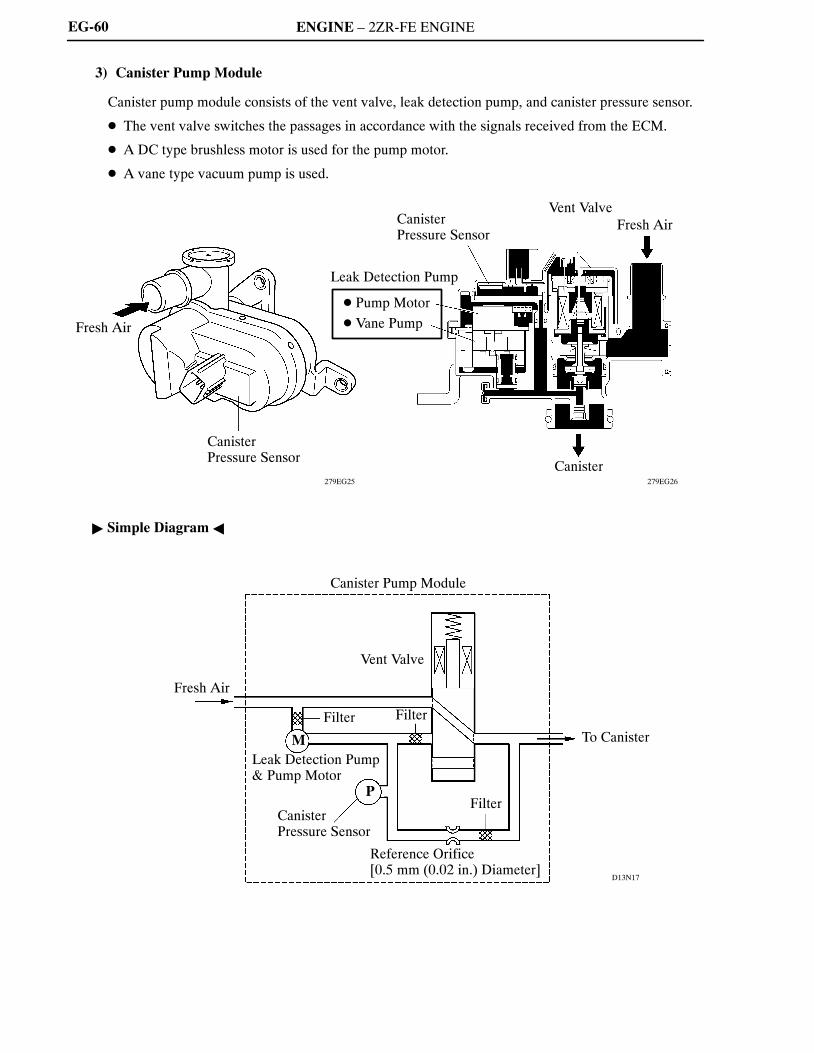
3) Canister Pump Module
Canister pump module consists of the vent valve, leak detection pump, and canister pressure sensor.
� The vent valve switches the passages in accordance with the signals received from the ECM.
� A DC type brushless motor is used for the pump motor.
� A vane type vacuum pump is used.
� Simple Diagram �

ENGINE – 2ZR-FE ENGINE
00REG23Y
Purge VSV(Open)
To Intake ManifoldAtmosphere
ECM
00REG24Y
Close
Open
EG-61
System Operation
1) Purge Flow Control
When the engine has satisfied the predetermined conditions (closed loop, engine coolant temperatureabove 74�C (165�F), etc.), the stored vapor gas is purged from the canister whenever the purge VSV isopened by the ECM.The ECM will change the duty ratio cycle of the purge VSV, thus controlling purge flow volume. Purgeflow volume is determined by intake manifold pressure and the duty ratio cycle of the purge VSV.Atmospheric pressure is allowed into the canister to ensure that purge flow is constantly maintainedwhenever purge vacuum is applied to the canister.
2) ORVR (On-board Refueling Vapor Recovery)
When the internal pressure of the fuel tank increases during refueling, this pressure causes the diaphragmin the refueling valve to lift up, allowing the vapor gas to enter the canister. Because the vent valve isalways open (even when the engine is stopped) when the system is in a mode other than the monitoringmode, the air that has been cleaned through the canister is discharged outside the vehicle via the freshair line. If the vehicle is refueled in the monitoring mode, the ECM will recognize the refueling by wayof the canister pressure sensor, which detects the sudden pressure increase in the fuel tank, and will openthe vent valve.

ENGINE – 2ZR-FE ENGINE
060XA19C
PurgeVSV
VentValve
Pump Motor
System Pressure
ON (Open)
OFF (Close)
ONOFF (Vent)
ONOFF
Atmospheric Pressure
0.02 in. Leak Pressure
1) 2) 3) 4) 5) 6)
EG-62
3) EVAP Leak Check
a. General
The EVAP leak check operates in accordance with the following timing chart:
� Timing Chart �
Order Operation Description Time
1)Atmospheric PressureMeasurement
ECM turns vent valve OFF (vent) and measures EVAPcontrol system pressure to memorize atmosphericpressure.
10 sec.
2)0.02 in. LeakPressure Measurement
Leak detection pump creates negative pressure (vacuum)through 0.02 in. orifice and the pressure is measured.ECM determines this as 0.02 in. leak pressure.
60 sec.
3) EVAP Leak Check
Leak detection pump creates negative pressure (vacuum)in EVAP control system and EVAP control systempressure is measured. If stabilized pressure is larger than0.02 in. leak pressure, ECM determines EVAP controlsystem has a leakage.If EVAP control system pressure does not stabilize within12 minutes, ECM cancels EVAP monitor.
Within12 min.
4) Purge VSV MonitorECM opens purge VSV and measures EVAP controlsystem pressure increase. If increase is large, ECMinterprets this as normal.
10 sec.
5)Repeat 0.02 in. LeakPressure Measurement
Leak detection pump creates negative pressure (vacuum)through 0.02 in. orifice and pressure is measured. ECMdetermines this as 0.02 in. leak pressure.
60 sec.
6) Final CheckECM measures atmospheric pressure and records monitorresult.
—

ENGINE – 2ZR-FE ENGINE
00REG25Y
D13N22
Purge VSV(OFF)
Atmosphere
ECM
Canister Pump Module
Vent Valve(OFF)
M
P
Leak Detection Pump& Pump Motor
CanisterPressure Sensor
Purge VSV
Vent Valve
Pump Motor
System Pressure
ON (Open)
OFF (Close)
ONOFF (Vent)
ON
OFF
Atmospheric Pressure
0.02 in. Leak Pressure
Atmospheric Pressure Measurement
EG-63
b. Atmospheric Pressure Measurement
1) When the ignition switch is turned OFF, the purge VSV and vent valve are turned OFF. Therefore,the atmospheric pressure is introduced into the canister.
2) The ECM measures the atmospheric pressure through the signals provided by the canister pressuresensor.
3) If the measurement value is out of standards, the ECM actuates the leak detection pump in order tomonitor the changes in the pressure.

ENGINE – 2ZR-FE ENGINE
00REG26Y
036EG126TE
Purge VSV(OFF)
Atmosphere
ECM
Canister Pump Module
Vent Valve(OFF)
Leak Detection Pump& Pump Motor
Canister PressureSensor
M
P
Reference Orifice
Purge VSV
Vent Valve
Pump Motor
System Pressure
ON (Open)OFF (Close)
ONOFF (Vent)
ONOFF
Atmospheric Pressure
0.02 in. Leak Pressure
0.02 in. Leak Pressure Measurement
EG-64
c. 0.02 in. Leak Pressure Measurement
1) The vent valve remains OFF, and the ECM introduces atmospheric pressure into the canister andactuates the leak detection pump in order to create a negative pressure.
2) At this time, the pressure will not decrease beyond a 0.02 in. leak pressure due to the atmosphericpressure that enters through a 0.02 in. diameter reference orifice.
3) The ECM compares the logic value with this pressure, and stores it as a 0.02 in. leak pressure in itsmemory.
4) If the measurement value is below the standard, the ECM will determine that the reference orificeis clogged and store DTC (Diagnostic Trouble Code) P043E in its memory.
5) If the measurement value is above the standard, the ECM will determine that a high flow rate pressureis passing through the reference orifice and store DTCs (Diagnostic Trouble Codes) P043F, P2401and P2402 in its memory.

ENGINE – 2ZR-FE ENGINE
00REG27Y
036EG127TE
Purge VSV(OFF)
Atmosphere
ECM
Canister Pump Module
Vent Valve(ON)
Leak Detection Pump& Pump Motor
CanisterPressure Sensor
M
P
Reference Orifice
Vacuum
Purge VSV
Vent Valve
Pump Motor
System Pressure
OFF (Close)
ON (Open)
ON
OFF (Vent)
ON
OFF
Atmospheric Pressure
0.02 in. leak Pressure
P0455
P0456
Normal
EVAP Leak Check
EG-65
d. EVAP Leak Check
1) While actuating the leak detection pump, the ECM turns ON the vent valve in order to introduce avacuum into the canister.
2) When the pressure in the system stabilizes, the ECM compares this pressure with the 0.02 in. leakpressure in order to check for a leakage.
3) If the measurement value is below the 0.02 in. leak pressure, the ECM determines that there is noleakage.
4) If the measurement value is above the 0.02 in. leak pressure and near atmospheric pressure, the ECMdetermines that there is a gross leakage (large hole) and stores DTC P0455 in its memory.
5) If the measurement value is above the 0.02 in. leak pressure, the ECM determines that there is a smallleakage and stores DTC P0456 in its memory.

ENGINE – 2ZR-FE ENGINE
00REG28Y
036EG128TE
Atmosphere
Purge VSV(ON)
ECM
Atmosphere
Canister Pump Module
Vent Valve(ON)
Leak Detection Pump& Pump Motor
CanisterPressure Sensor
M
P
Purge VSV
Vent Valve
Pump Motor
System Pressure
ON (Open)
OFF (Close)
ONOFF (Vent)
ONOFF
Atmospheric Pressure
0.02 in. leak Pressure
Normal
P0441
Purge VSV Monitor
EG-66
e. Purge VSV Monitor
1) After completing an EVAP leak check, the ECM turns ON (open) the purge VSV with the leakdetection pump actuated, and introduces the atmospheric pressure from the intake manifold to thecanister.
2) If the pressure change at this time is within the normal range, the ECM determines the condition tobe normal.
3) If the pressure is out of the normal range, the ECM will stop the purge VSV monitor and store DTCP0441 in its memory.

ENGINE – 2ZR-FE ENGINE
01MEG03Y
036EG129TE
Purge VSV(OFF)
ECM
Atmosphere
Canister Pump Module
Vent Valve(OFF)
M
P
Leak Detection Pump& Pump Motor
Canister PressureSensor Reference Orifice
Purge VSV
Vent Valve
Pump Motor
System Pressure
ON (Open)OFF (Close)
ONOFF (Vent)
ONOFF
Atmospheric Pressure
0.02 in. leak Pressure
P0456
Normal
Repeat 0.02 in. Leak Pressure Measurement
EG-67
f. Repeat 0.02 in. Leak Pressure Measurement
1) While the ECM operates the vacuum pump, the purge VSV and vent valve turn off and a repeat 0.02in. leak pressure measurement is performed.
2) The ECM compares the measured pressure with the pressure during EVAP leak check.
3) If the pressure during the EVAP leak check is below the measured value, the ECM determines thatthere is no leakage.
4) If the pressure during the EVAP leak check is above the measured value, the ECM determines thatthere is a small leakage and stores DTC P0456 in its memory.

ENGINE – 2ZR-FE ENGINE
04FEG27Y
Engine CoolantTemperature Sensor
Combination Meter
Vehicle Speed Signal
Crankshaft PositionSensor
From Battery
From Ignition Switch
ECM
CAN (V Bus)
Air Conditioning Amplifier*
Cooling FanRelay
Cooling FanMotor
CoolingFan ECU
EG-68
10. Cooling Fan Control System
General
A cooling fan control system is used. To achieve an optimal fan speed in accordance with the engine coolanttemperature, vehicle speed, engine speed, and air conditioning operating conditions*, the ECM calculatesthe proper fan speed and sends the signals to the cooling fan ECU. Upon receiving the signals from the ECM,the cooling fan ECU actuates the fan motors. Also, the fan speed is controlled by the ECUs using the steplesscontrol.
� Wiring Diagram �
*: Models with Air Conditioning System

ENGINE – 2ZR-FE ENGINE
189EG14189EG13
189EG16189EG15
FanSpeed
(A) Fan speed required byengine coolant temperature
Engine CoolantTemperature
FanSpeed
RefrigerantPressure
(B) Fan speed required byair conditioningrefrigerant pressure
FanSpeed
FanSpeed
Engine Speed
(C) Fan speed required byengine speed
Vehicle Speed
(D) Fan speed required byvehicle speed
EG-69
Operation
As illustrated below, the ECM determines the required fan speed by selecting the fastest fan speed fromamong the following:(A) The fan speed required by the engine coolant temperature, (B) the fan speed required by the airconditioning refrigerant pressure, (C) the fan speed required by the engine speed, and (D) the fan speedrequired by the vehicle speed.

ENGINE – 2ZR-FE ENGINE
00SEG55Y
Battery
Ignition Switch
Starter
ACC Cut Relay
� Clutch Switch*1
� Park/Neutral Position Switch*2
StarterRelay
ECM
ACCR
STSW
STAR
STA
� Engine Speed Signal� Engine Coolant
Temperature Signal
EG-70
11. Starter Control (Cranking Hold Function)
General
1) For Models without Smart Key System
� Once the ignition switch is turned to the START position, this control continues to operate the starteruntil the engine starts, without having to hold the ignition switch in the START position. This preventsstarting failures.
� When the ECM detects a start signal from the ignition switch, this system monitors the engine speed(NE) signal and continues to operate the starter until it determines that the engine has started.
� System Diagram �
*1: Manual Transaxle Models*2: Automatic Transaxle Models

ENGINE – 2ZR-FE ENGINE
04FEG32Y
PUSH
Engine Switch
Brake Pedal
Battery
Main Body ECU(Instrument PanelJunction Block)
STP
ACC Relay
Starter
IG
ST CutRelay
Park/NeutralPositionSwitch
StarterRelay
ECM
STSWACCRSTAR
STA
� Engine Speed Signal� Engine Coolant
Temperature Signal
EG-71
2) For Models with Smart Key System
� Once the engine switch is pushed, this function continues to operate the starter until the engine starts,provided that the brake pedal is pressed. This prevents starting failures and the engine from beingcranked after the engine has started.
� When the ECM detects a start signal from the main body ECU, this system monitors the engine speed(NE) signal and continues to operate the starter until it determines that the engine has started.Furthermore, even if the ECM detects a start signal from the main body ECU, this system will notoperate the starter if the ECM has determined that the engine has already started.
� If the starter relay (STAR) signal cannot be output because the power supplied to the ECM is low, themain body ECU outputs the starter relay (STAR) signal instead to help actuate the starter.
� System Diagram �

ENGINE – 2ZR-FE ENGINE
00SEG57Y
Ignition SwitchPosition
Starter Relay
Accessory Power
Engine Speed Signal(NE)
START
ON
ON
OFFON
OFF
Cranking LimitApprox. 2 to 25 sec.
SuccessfulStarting of Engine
Failed Starting ofEngine
ECM determines that the engine has startedsuccessfully when the engine speed isapproximately 500 rpm.
EG-72
Operation
1) For Models without Smart Key System
� As indicated in the following timing chart, when the ECM detects a start signal from the ignitionswitch, it energizes the starter relay to operate the starter. If the engine is already running, the ECMwill not energize the starter relay.
� After the starter operates and the engine speed becomes higher than approximately 500 rpm, the ECMdetermines that the engine has started and stops the operation of the starter.
� If the engine has any failure and does not work, the starter operates as long as its maximum continuousoperation time and stops automatically. The maximum continuous operation time is approximately2 seconds through 25 seconds depending on the engine coolant temperature condition. When theengine coolant temperature is extremely low, it is approximately 25 seconds and when the engine iswarmed up sufficiently, it is approximately 2 seconds.
� This system cuts off the current that powers the accessories while the engine is cranking to preventthe accessory illumination from operating intermittently due to the unstable voltage that is associatedwith the cranking of the engine.
� This system has the following protections.
– In case that the starter begins to operate, but cannot detect the engine speed signal, the ECM willstop the starter operation immediately. However, if the ignition switch is held in the STARTposition, the starter continues to operate.
� Timing Chart �

ENGINE – 2ZR-FE ENGINE
00SEG57Y
Start Signal
Starter Relay
Accessory Power
Engine Speed Signal(NE)
ON
OFF
ON
OFF
ON
OFF
Cranking LimitApprox. 2 to 25 sec.
SuccessfulStarting of Engine
Failed Starting ofEngine
ECM determines that the engine has startedsuccessfully when the engine speed isapproximately 500 rpm.
EG-73
2) For Models with Smart Key System
� As indicated in the following timing chart, when the ECM detects a start signal (STSW) from the mainbody ECU, the ECM outputs the STAR and ACCR signals to the main body ECU. Upon detecting theSTAR and ACCR signals from the ECM, the main body ECU energizes the starter relay to operatethe starter. If the engine is already running, the ECM stops the output of the STAR and ACCR signalsto the main body ECU. Thus, the main body ECU will not energize the starter relay.
� After the starter operates and the engine speed becomes higher than approximately 500 rpm, the ECMdetermines that the engine has started and stops the output of the STAR and ACCR signals to the mainbody ECU. Thus, the main body ECU will stop the operation of the starter.
� If the engine has any failure and does not work, the starter operates as long as its maximum continuousoperation time and stops automatically. The maximum continuous operation time is approximately2 seconds through 25 seconds depending on the engine coolant temperature condition. When theengine coolant temperature is extremely low, it is approximately 25 seconds and when the engine iswarmed up sufficiently, it is approximately 2 seconds.
� This system cuts off the current that powers the accessories while the engine is cranking to preventthe accessory illumination from operating intermittently due to the unstable voltage that is associatedwith the cranking of the engine.
� This system has the following protections.– While the engine is running normally, the starter does not operate.– In case the driver keeps pressing the engine switch and the engine successfully started, the ECM
stops the output of the STAR and ACCR signals when the engine speed becomes higher than 1,200rpm. Thus, the main body ECU will stop the operation of the starter.
– In case the driver keeps pressing the engine switch and the engine does not start, the ECM stopsthe output of the STAR and ACCR signals after 30 seconds have elapsed. Thus, the main body ECUwill stop the operation of the starter.
– In case the ECM cannot detect an engine speed signal while the starter is operating, the ECM willimmediately stop the output of the STAR and ACCR signals. Thus, the main body ECU will stopthe operation of the starter.
� Timing Chart �

ENGINE – 2ZR-FE ENGINE
Service Tip
To clear the DTC that is stored in the ECM, use a Techstream or disconnect the battery terminal orremove the EFI fuse for 1 minute or longer.
EG-74
12. Diagnosis
� When the ECM detects a malfunction, the ECM makes a diagnosis and memorizes the failed section.Furthermore, the MIL in the combination meter illuminates or blinks to inform the driver.
� The ECM will also store the DTCs of the malfunctions. The DTCs can be accessed by the use of theTechstream.
� For details, refer to the 2009 Corolla Repair Manual (Pub. No. RM08M0U).
13. Fail-safe
When a malfunction is detected at any of the sensors, there is a possibility of an engine or other malfunctionoccurring if the ECM were to continue to control the engine control system in the normal way. To preventsuch a problem, the fail-safe function of the ECM either relies on the data stored in memory to allow theengine control system to continue operating, or stops the engine if a hazard is anticipated. For details, referto the 2009 Corolla Repair Manual (Pub. No. RM08M0U).
Copyright 2011 - 2014 Service Repair Solutions, Inc.