Embed Size (px)
Citation preview

© 2020 Eaton. All rights reserved..
Understanding diesel
cylinder deactivation
October 21, 2020
Engage the Experts

© 2020 Eaton. All rights reserved..
Tony TrueloveGlobal Marketing Communications Manager, Eaton
• Welcome!
• Fourth in a series of
webinars on diesel
cylinder deactivation
• Feel free to send us
questions

© 2020 Eaton. All rights reserved..
Engage the Experts: free webinars on commercial vehicle engine strategies
September 9 The truth about diesel CDA and NVHTom Reinhart, Southwest Research Institute (SwRI)
September 30 Achieving 2027 emissions regulationsChris Sharp, Southwest Research Institute (SwRI)
October 14 The advantages of CDA over real-world drive cyclesDr. Mrunal Joshi, Cummins
October 21 Understanding diesel cylinder deactivationDr. Greg Shaver, Purdue University
October 28 CDA versus cylinder cutout: a technology overview Dr. Cody Allen, University of Illinois

© 2020 Eaton. All rights reserved..
Today’s discussion
• Based on extensive
research from 30
published papers
• List can be downloaded
from the Resources area

© 2020 Eaton. All rights reserved..
Dr. Dheeraj GosalaResearch engineer, Cummins
• Dheeraj Gosala is a research engineer in the Advanced Systems Performance group in Cummins Research & Technology. He works on advanced controls development for next-generation spark-ignited and diesel engine systems within electrified commercial vehicle powertrains.
• Dheeraj graduated with a PhD from Purdue University in 2018. His doctoral dissertation investigated the potential of diesel engine variable valve actuation, including cylinder deactivation, in achieving fuel-efficient emissions reduction.

© 2020 Eaton. All rights reserved..
Dr. Cody AllenAssistant Professor, University of Illinois
• Cody Allen is an Assistant Professor at the University of
Illinois at Urbana-Champaign in the Department of
Agricultural and Biological Engineering.
• His research focuses on creating cleaner, more efficient
heavy-duty vehicles by exploring advanced powertrain
technologies and architectures, including works resulting in
over a half-dozen peer-reviewed publications related to
diesel engine variable valve actuation and cylinder
deactivation. He also develops model-based control
algorithms and validation tools for machine automation
leading to improved productivity, efficiency, and safety.
• Prior to joining the faculty at the University of Illinois, Cody
worked as a Guidance, Navigation, and Control Engineer for
Boeing Defense, Space & Security.
• He received a PhD in Mechanical Engineering from Purdue
University in 2019, MSME from Purdue in 2016, and BSME
with high honors from the University of Illinois in 2014

© 2020 Eaton. All rights reserved..
Dr. James McCarthy, Jr.Chief Engineer for Vehicle Technologies and Innovation, Eaton
• Prior to joining Eaton, Jim worked on
diesel engine technologies at Detroit
Diesel
• Focused on product innovation and
growth to develop solutions for engine
technologies to conserve fossil fuels
and reduce emissions
• Holds a Ph.D., Masters of Science and
Bachelors of Science in Mechanical
Engineering from Purdue University

© 2020 Eaton. All rights reserved..
Dr. Eckhard GrollHead of the School of Mechanical Engineering, Purdue University
• Dr. Eckhard A. Groll is the Reilly Professor of Mechanical Engineering
and also serves as the Head of Mechanical Engineering.
• He received his Diploma in Mechanical Engineering from the University of the Ruhr in Bochum, Germany, in 1989 and a Doctorate in Mechanical
Engineering from the University of Hannover, Germany, in 1994.
• Prof. Groll teaches thermodynamics and his research focuses on the fundamental thermal sciences as applied to advanced energy conversion
systems, components, and their working fluids. He is a world-renown expert in positive displacement compressors and expanders.
• He has been the principal investigator or co-principal investigator on
more than 120 research grants and more than 40 educational grants from various governmental agencies, professional societies, and more
than 30 different industrial sponsors.
• He has authored or co-authored more than 370 archival journal articles and conference papers. He has been the co-author of 4 book chapters
and the editor or co-editor of 7 conference proceedings.
• He serves as the Regional Editor for the Americas for the International Journal of Refrigeration and is a fellow of the American Society of
Heating, Refrigerating, and Air Conditioning Engineers (ASHRAE).

MECHANICAL ENGINEERINGSTATEOF THESCHOOL
EckhardA. Groll
9

Undergraduates
10
▪ More than 97% of Purdue ME
students graduate with industry
experience (internships, co-ops, and
research)
▪ 75% of graduates go to work in
industry (automotive, aerospace,
defense, energy, biomedicine,
manufacturing, management, and
much more!)

Company-Sponsored Student Design Projects
11
▪ 14 senior design projects (approx. 28% of all teams) were direct collaborations with industry partners
• Teams of 4-6 seniors spend their final semester tackling a company’s engineering issue
• Could be a manufacturing problem, a new feature for an existing product, or any other issue large or small
• Many companies implement their designs, and hire the students right after graduation!
▪ Corporate Partners Program has grown to
include 13 partners(Phillips 66, EBI, Modineer, ArcelorMittal, Eaton, Lilly,
Sandia, Norfolk Southern, Exxon, Altair, Lawrence
Livermore, Air Products, Whirlpool)

A Master’s Degree for Working Professionals
12
▪ 26% of Purdue ME graduate students
are fully online
▪ Purdue ME’s Online Masters program
ranked #1 in the country by US News
& World Report
▪ Flexibility for working professionals,
anywhere in the world
▪ purdue.edu/ME/online
“This degree has opened doors for me into a
new position on the research side here at
3M. Corporate R&D is something I had
always wanted to get into from the beginning,
and this Purdue program has really enabled
that to happen.”

Purdue is a Research Powerhouse
13
▪ Purdue generates half a billion dollars in research funding every year
▪ World-class facilities and labs found nowhere else
▪ 90 mechanical engineering faculty in 21 different research areas
▪ $38.1 million in research expenditures in 2019-20
▪ More than a 50% increase in just 4 years!
▪ Just recently:
• $8M from US Army for Energetic Materials research
• $5M from NSF to use augmented reality in
manufacturing worker education
• $5M from NSF for precision agriculture with
Internet-of-Things

14
Research Area Chart

Many ways to get involved!
15
▪ There’s a place for your research at Purdue!
▪ Sponsor a project with one faculty, or participate
in a research center
▪ Share costs with government-funded projects
from DOE, DOD, NASA, etc.
▪ Small-business grants
available for startup companies
▪ Purdue has decades of
experience with hundreds of
corporate partners!

© 2020 Eaton. All rights reserved..
Dr. Greg ShaverProfessor of Engineering, Purdue University
• Dr. Shaver is a Full Professor, University Faculty Scholar, and College of Engineering Early Career Research Award recipient. He joined the Purdue Faculty in 2006.
• He is focused on creating challenging, interesting, relevant, career-launching research and learning opportunities for Purdue students. His research program is dedicated to clean, safe, and efficient commercial vehicles – via advanced diesel & natural gas engine systems/controls, powertrain electrification, and vehicle automation/connectivity.
• His efforts are well known in the industry and regulatory agencies, including the U.S. EPA and California Air Resources Board. This is a result of Greg’s students and industry collaborators demonstrating that future diesel engines can simultaneously reduce emissions (NOx and soot), fuel consumption, and CO2 emissions through the use of variable valve actuation (VVA) and cylinder deactivation.
• Greg earned graduate (PhD 2005, MSME 2004) and undergraduate (BSME 2000 w/ highest distinction) degrees from Stanford and Purdue, respectively.

Understanding Diesel Engine Cylinder Deactivation(and some context relative to other approaches)
October 21st, 2020
PI: Dr. Gregory Shaver
Project management: Eric Holloway
With funding from, and in collaboration with:
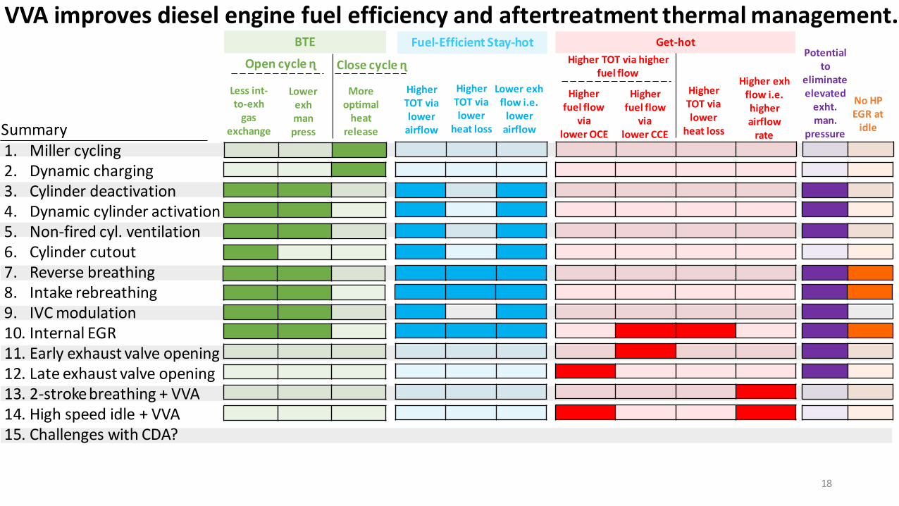
VVA improves diesel engine fuel efficiency and aftertreatment thermal management.BTE Fuel-Efficient Stay-hot Get-hot
Open cycle ɳ Close cycle ɳ
Lower exhman press
Moreoptimal
heat release
Higher TOT via lower
heat loss
Higher TOT via lower
airflow
Lower exhflow i.e.
lower airflow
Higher exhflow i.e. higherairflow
rate
Potential to
eliminate elevated
exht. man.
pressure
No HP EGR at
idle
HigherTOT via lower
heat loss
Less int-to-exh
gas exchange
1. Miller cycling2. Dynamic charging. .3. Cylinder deactivation4. Dynamic cylinder activation5. Non-fired cyl. ventilation 6. Cylinder cutout7. Reverse breathing 8. Intake rebreathing. . . . . . . . . . . . . 9. IVC modulation10. Internal EGR11. Early exhaust valve opening12. Late exhaust valve opening13. 2-stroke breathing + VVA14. High speed idle + VVA 15. Challenges with CDA?
Higher fuel flow
vialower OCE
Higher TOT via higher fuel flow
Higher fuel flow
vialower CCESummary
18

VVA improves diesel engine fuel efficiency and aftertreatment thermal management.BTE Fuel-Efficient Stay-hot Get-hot
Open cycle ɳ Close cycle ɳ
Lower exhman press
Moreoptimal
heat release
Higher TOT via lower
heat loss
Higher TOT via lower
airflow
Lower exhflow i.e.
lower airflow
Higher exhflow i.e. higherairflow
rate
Potential to
eliminate elevated
exht. man.
pressure
No HP EGR at
idle
HigherTOT via lower
heat loss
Less int-to-exh
gas exchange
1. Miller cycling2. Dynamic charging. .3. Cylinder deactivation4. Dynamic cylinder activation5. Non-fired cyl. ventilation 6. Cylinder cutout7. Reverse breathing 8. Intake rebreathing. . . . . . . . . . . . . 9. IVC modulation10. Internal EGR11. Early exhaust valve opening12. Late exhaust valve opening13. 2-stroke breathing + VVA14. High speed idle + VVA 15. Challenges with CDA?
Higher fuel flow
vialower OCE
Higher TOT via higher fuel flow
Higher fuel flow
vialower CCESummary
19Presentation focus is cylinder deactivation (CDA), but I will draw comparisons to several other methods.

Experimental Setup at Purdue University
Cummins Power Lab – Test Cell 1
Aftertreatment systemDOC-DPF-SCR
Cummins 6-cylindercamless diesel engine
Fully flexible VVA systemCylinder-to-cylinder, cycle-by-cycle control
MeasurementsEmissions, temperatures, pressures, flow rates etc.
20

Experimental Setup at Purdue University
Cummins Power Lab – Test Cell 1
Aftertreatment systemDOC-DPF-SCR
Cummins 6-cylindercamless diesel engine
Fully flexible VVA systemCylinder-to-cylinder, cycle-by-cycle control
MeasurementsEmissions, temperatures, pressures, flow rates etc.
21

Experimental Setup at Purdue University
Cummins Power Lab – Test Cell 1
DOCDPFSCR
Aftertreatment systemDOC-DPF-SCR
Cummins 6-cylindercamless diesel engine
Fully flexible VVA systemCylinder-to-cylinder, cycle-by-cycle control
MeasurementsEmissions, temperatures, pressures, flow rates etc.
22

Experimental Setup at Purdue University
Cummins Power Lab – Test Cell 1
Aftertreatment systemDOC-DPF-SCR
Cummins 6-cylindercamless diesel engine
Fully flexible VVA systemCylinder-to-cylinder, cycle-by-cycle control
MeasurementsEmissions, temperatures, pressures, flow rates etc.
23

Fuel Efficiency
Close Cycle Efficiency
Open CycleEfficiency
Mechanical Efficiency
Expansion
Exhaust
Expansion
Exhaust
Compression
Intake
Area of pumping loop ∝ 𝟏
𝑶𝒑𝒆𝒏 𝑪𝒚𝒄𝒍𝒆 𝑬𝒇𝒇𝒊𝒄𝒊𝒆𝒏𝒄𝒚
Closed loop
log
P
log V
Potential for fuel efficiency improvements with VVA
Pumping (Open) loop
24
Ways to increase open cycle efficiency - Reduce intake-to-exhaust manifold gas exchange
- Use VVA to lower per cylinder int.-to-exht. man. gas exchange (iEGR, IVC)
- Use VVA to decrease # of cylinders exchanging gas from int-to-exht. man. (CDA, DCA, NFCV, rev. breathing, cyl. cut, etc.)
- Lower exhaust manifold pressure- Use VVA to reduce back pressure req’d for thermal management or
to drive HP EGR (CDA, DCA, NFCV, rev. breathing, iEGR, IVC)

BTE Fuel-Efficient Stay-hot Get-hot
Open cycle ɳ Close cycle ɳ
Lower exhman press
Moreoptimal
heat release
Higher TOT via lower
heat loss
Higher TOT via lower
airflow
Lower exhflow i.e.
lower airflow
Higher exhflow i.e. higherairflow
rate
No HP EGR at
idle
HigherTOT via lower
heat loss
Less int-to-exh
gas exchange
1. Miller cycling2. Dynamic charging. .3. Cylinder deactivation4. Dynamic cylinder activation5. Non-fired cyl. ventilation 6. Cylinder cutout7. Reverse breathing 8. Intake rebreathing. . . . . . . . . . . . . 9. IVC modulation10. Internal EGR11. Early exhaust valve opening12. Late exhaust valve opening13. 2-stroke breathing + VVA14. High speed idle + VVA 15. Challenges with CDA?
Higher fuel flow
vialower OCE
Higher TOT via higher fuel flow
Higher fuel flow
vialower CCESummary
25
Potential to
eliminate elevated
exht. man.
pressure
VVA improves diesel engine fuel efficiency and aftertreatment thermal management.

Conventional six-cylinder operation Fixed CDA – 3 cylinders firing (3 CF)
Fixed CDA – 2 cylinders firing (2 CF)Fixed CDA – 4 cylinders firing (4 CF)
• Both valve actuation and fuel injection are disabled
• Fuel injected in the active cylinders is increased to meet torque/power
• Fixed set of cylinders are deactivated every engine cycle
Cylinder Deactivation
26

Cylinder Deactivation – 800 rpm, 1.3 bar (curb idle)
140
160
180
200
220
240
260
0.8 1 1.2 1.4 1.6
Turb
ine
Ou
tlet
Tem
per
atu
re (°
C)
Normalized Fuel Consumption
TM 6CF
FE 6CF
60% more fuel
120°C higher
6 cylinder operation
(6CF)TM – conventional thermal management mode
FE – conventional fuel efficient mode
27

Cylinder Deactivation – 800 rpm, 1.3 bar (curb idle)
140
160
180
200
220
240
260
0.8 1 1.2 1.4 1.6
Turb
ine
Ou
tlet
Tem
per
atu
re (°
C)
Normalized Fuel Consumption
3CF
FE 6CF
41% fuel savings
TM 6CF
~60°C higher
Fixed CDA (3CF)
6 cylinder operation
(6CF)
28
CDA achieves elevated engine-out temperatures at lower fuel consumption

Cylinder Deactivation – 800 rpm, 1.3 bar (curb idle)
140
160
180
200
220
240
260
0.8 1 1.2 1.4 1.6
Turb
ine
Ou
tlet
Tem
per
atu
re (°
C)
Normalized Fuel Consumption
3CF 41% fuel savings
~60°C higher
TM 6CF2CF
39% fuel savingsFixed CDA
(2CF)
Fixed CDA (3CF)
~120°C higher
FE 6CF
6 cylinder operation
(6CF)
29
CDA achieves elevated engine-out temperatures at lower fuel consumption

Cylinder Deactivation – 800 rpm, 1.3 bar (curb idle)
140
160
180
200
220
240
260
0.8 1 1.2 1.4 1.6
Turb
ine
Ou
tlet
Tem
per
atu
re (°
C)
Normalized Fuel Consumption
3CF 41% fuel savings
~60°C higher
TM 6CF2CF
39% fuel savings
CDA achieves elevated engine-out temperatures at lower fuel consumption
~120°C higher
FE 6CF0
0.2
0.4
0.6
0.8
1
1.2
0 1 2 3 4
No
rmal
ized
NO
x fl
ow
rat
e
Normalized soot flow rate
2CF
3CF
TM 6CF
FE 6CF
CDA shows lower engine-out NOx and soot emissions than conventional 6-cylinder thermal management operation
Normalized exhaust flow rates
TM 6CF FE 6CF 3 CF 2 CF 30

Cylinder Deactivation – Elev. Ext. Man. Pressure, at 800 rpm, 1.3 bar (curb idle)
140
160
180
200
220
240
260
0.8 1 1.2 1.4 1.6
Turb
ine
Ou
tlet
Tem
per
atu
re (°
C)
Normalized Fuel Consumption
3CF
FE 6CF
41% fuel savings
~60°C higher
TM 6CF2CF
39% fuel savings
~120°C higher
CDA can achieve elevated engine-out temperatures at lower fuel consumption
without requiring elevated exhaust manifold pressure (EEMP)
3CF w/o EEMP
0
0.2
0.4
0.6
0.8
1
1.2
0 1 2 3 4
No
rmal
ized
NO
x fl
ow
rat
e
Normalized soot flow rate
3CF
TM 6CF
FE 6CF
3CF w/o EEMP
31
2CF

Cylinder Deactivation – CDA+LIVC and CDA+iEGR at 800 rpm, 1.3 bar (curb idle)
140
160
180
200
220
240
260
0.8 1 1.2 1.4 1.6
Turb
ine
Ou
tlet
Tem
per
atu
re (°
C)
Normalized Fuel Consumption
3CF
FE 6CF
41% fuel savings
~60°C higher
TM 6CF2CF
39% fuel savings
~120°C higher3CF+LIVC
3CF+iEGR
3CF+iEGR
• CDA+LIVC : Higher TOT, lower fuel consumption than 3CF• CDA+iEGR : Enables improved TOT vs FC tradeoff
.1
.1
.1
0
0.2
0.4
0.6
0.8
1
1.2
0 1 2 3 4
No
rmal
ized
NO
x fl
ow
rat
e
Normalized soot flow rate
3CF
TM 6CF
FE 6CF
• CDA+LIVC • CDA+iEGR
Within desired emission constraints
.1
3CF+iEGR.1
3CF+iEGR
.1
3CF+LIVC
32
2CF

300
350
400
450
500
550
600
1 1.1 1.2 1.3 1.4
Turb
ine
Ou
tlet
Tem
per
atu
re (d
eg C
)
Normalized Fuel Consumption
FE 6CF
• CDA yields higher engine-outlet temperatures than 6-cylinder operation, making it possible to perform DPF regeneration during highway cruise
• Fuel penalty with respect to best BSFC 6-cyl operation
Active DPF regen
Cylinder Deactivation – Highway cruise 1200 rpm, 7.6 bar
3CF
4CF
6CF
33

0.7
0.8
0.9
1
1.3 2.5 3.8 5.1 6.4
No
rma
lize
d F
ue
l Co
nsu
mp
tio
n
BMEP (bar)
CDA results in 4-25% fuel savings, depending on engine load, and yields up to 200 deg C higher engine-out temperatures
Cylinder Deactivation – 2200 rpm, 1.3-5.2 bar
FE 6CF3CF
34

BTE Fuel-Efficient Stay-hot Get-hot
Open cycle ɳ Close cycle ɳ
Lower exhman press
Moreoptimal
heat release
Higher TOT via lower
heat loss
Higher TOT via lower
airflow
Lower exhflow i.e.
lower airflow
Higher exhflow i.e. higherairflow
rate
No HP EGR at
idle
HigherTOT via lower
heat loss
Less int-to-exh
gas exchange
1. Miller cycling2. Dynamic charging. .3. Cylinder deactivation4. Dynamic cylinder activation5. Non-fired cyl. ventilation 6. Cylinder cutout7. Reverse breathing 8. Intake rebreathing. . . . . . . . . . . . . 9. IVC modulation10. Internal EGR11. Early exhaust valve opening12. Late exhaust valve opening13. 2-stroke breathing + VVA14. High speed idle + VVA 15. Challenges with CDA?
Higher fuel flow
vialower OCE
Higher TOT via higher fuel flow
Higher fuel flow
vialower CCESummary
35
Potential to
eliminate elevated
exht. man.
pressure
VVA improves diesel engine fuel efficiency and aftertreatment thermal management.

Dynamic Cylinder Activation (DCA)
Form of CDA with a different set of active cylinders each engine cycle
Fixed Cylinder DeactivationFixed CDA (3 CF)
Dynamic Cylinder ActivationDCA (3 CF equivalent)
36

Fixed CDA
DCA alternating pattern
DCA aperiodic pattern
Dynamic Cylinder Activation is studied using two ‘recipes’
37

0
0.2
0.4
0.6
0.8
1
1.2
0 1 2 3 4
No
rmal
ized
NO
x fl
ow
rat
e
Normalized soot flow rate
FE 6CF
DCA shows similar fuel savings, exhaust temperatures and emissions
as fixed CDA with equivalent number of cylinders firing
140
160
180
200
220
240
260
0.8 1 1.2 1.4 1.6
Normalized Fuel Consumption
DCA (3CF equivalent)
Turb
ine
Ou
tlet
Tem
per
atu
re (°
C)
3CF
3CF
DCA (3CF equivalent)
TM 6CF
FE 6CF
Dynamic Cylinder Activation at 800 rpm, 1.3 bar
TM 6CF2CF
38
2CF

Fixed CDA- 3 CF
Frequency
Six-cylinder operation
Torsional vibration in DCA- Additional degree of freedom
Torsional vibration(Ang Acc Flywheel)
39

Fixed CDA- 3 CF
DCA (alternating pattern)
DCA (aperiodic pattern)
Frequency
3 CF equivalent
3 CF equivalent
Six-cylinder operation
Torsional vibration in DCA- Additional degree of freedom
Acceptable torsional vibration –
Switch between fixed CDA and appropriate DCA
strategy depending on engine speed
Torsional vibration(Ang Acc Flywheel)
40

BTE Fuel-Efficient Stay-hot Get-hot
Open cycle ɳ Close cycle ɳ
Lower exhman press
Moreoptimal
heat release
Higher TOT via lower
heat loss
Higher TOT via lower
airflow
Lower exhflow i.e.
lower airflow
Higher exhflow i.e. higherairflow
rate
No HP EGR at
idle
HigherTOT via lower
heat loss
Less int-to-exh
gas exchange
1. Miller cycling2. Dynamic charging. .3. Cylinder deactivation4. Dynamic cylinder activation5. Non-fired cyl. ventilation 6. Cylinder cutout7. Reverse breathing 8. Intake rebreathing. . . . . . . . . . . . . 9. IVC modulation10. Internal EGR11. Early exhaust valve opening12. Late exhaust valve opening13. 2-stroke breathing + VVA14. High speed idle + VVA 15. Challenges with CDA?
Higher fuel flow
vialower OCE
Higher TOT via higher fuel flow
Higher fuel flow
vialower CCESummary
41
Potential to
eliminate elevated
exht. man.
pressure
VVA improves diesel engine fuel efficiency and aftertreatment thermal management.

Conventional Operation
CDA – 3CF140
160
180
200
220
240
260
0.8 1 1.2 1.4 1.6
Turb
ine
Ou
tle
t Te
mp
era
ture
(de
g C
)
Normalized Fuel Consumption
3 CF
2 CF TM 6CF
FE 6CF
Reverse breathing and intake rebreathing for stay-hot
800 rpm, 1.3 bar (curb idle)
42

Fired Reverse Breathing
• Uses no external EGR• Low airflow strategy
140
160
180
200
220
240
260
0.8 1 1.2 1.4 1.6
Turb
ine
Ou
tle
t Te
mp
era
ture
(de
g C
)
Normalized Fuel Consumption
3 CF
FRB-2cyl
FRB-1cyl
2 CF TM 6CF
FE 6CF
Reverse breathing and intake rebreathing for stay-hot
800 rpm, 1.3 bar (curb idle)
43

Non-Fired Reverse Breathing
140
160
180
200
220
240
260
0.8 1 1.2 1.4 1.6
Turb
ine
Ou
tle
t Te
mp
era
ture
(de
g C
)
Normalized Fuel Consumption
3 CF
FRB-2cyl
FRB-1cyl
NFRB-3cyl
2 CF TM 6CF
FE 6CF
• Uses no external EGR• Low airflow strategy
Reverse breathing and intake rebreathing for stay-hot
800 rpm, 1.3 bar (curb idle)
44

140
160
180
200
220
240
260
0.8 1 1.2 1.4 1.6
Turb
ine
Ou
tle
t Te
mp
era
ture
(de
g C
)
Normalized Fuel Consumption
3 CF
FRB-2cyl
FRB-1cylIRB-3cyl
NFRB-3cyl
Intake Rebreathing
TM 6CF
FE 6CF
Normalized exhaust flow rates
TM 6CF FE 6CF 3 CF 2 CF FRB-2cyl IRB-3cyl NFRB-3cyl
• Uses no external EGR• Low airflow strategy
Reverse breathing and intake rebreathing for stay-hot
2 CF800 rpm, 1.3 bar (curb idle)
45

140
160
180
200
220
240
260
0.8 1 1.2 1.4 1.6
Turb
ine
Ou
tle
t Te
mp
era
ture
(de
g C
)
Normalized Fuel Consumption
3 CF
FRB-2cyl
FRB-1cylIRB-3cyl
NFRB-3cyl
TM 6CF
FE 6CF
Normalized exhaust flow rates
TM 6CF FE 6CF 3 CF 2 CF FRB-2cyl IRB-3cyl NFRB-3cyl
Reverse breathing and intake rebreathing for stay-hot
2 CF800 rpm, 1.3 bar (curb idle)
0
0.2
0.4
0.6
0.8
1
1.2
0 1 2 3
No
rmal
ized
NO
x fl
ow
rat
e
Normalized soot flow rate
FE 6CF
TM 6CF
3 CF
NFRB-3cyl
FRB-2cyl
IRB-3cyl
46
2 CF

BTE Fuel-Efficient Stay-hot Get-hot
Open cycle ɳ Close cycle ɳ
Lower exhman press
Moreoptimal
heat release
Higher TOT via lower
heat loss
Higher TOT via lower
airflow
Lower exhflow i.e.
lower airflow
Higher exhflow i.e. higherairflow
rate
No HP EGR at
idle
HigherTOT via lower
heat loss
Less int-to-exh
gas exchange
1. Miller cycling2. Dynamic charging. .3. Cylinder deactivation4. Dynamic cylinder activation5. Non-fired cyl. ventilation 6. Cylinder cutout7. Reverse breathing 8. Intake rebreathing. . . . . . . . . . . . . 9. IVC modulation10. Internal EGR11. Early exhaust valve opening12. Late exhaust valve opening13. 2-stroke breathing + VVA14. High speed idle + VVA 15. Challenges with CDA?
Higher fuel flow
vialower OCE
Higher TOT via higher fuel flow
Higher fuel flow
vialower CCESummary
47
Potential to
eliminate elevated
exht. man.
pressure
VVA improves diesel engine fuel efficiency and aftertreatment thermal management.

Stock operation for fuel efficiency and thermal management
140
160
180
200
220
240
260
0.8 1 1.2 1.4 1.6
Turb
ine
Ou
tlet
Tem
per
atu
re (°
C)
Normalized Fuel Consumption
TM 6CF
FE 6CF
800 rpm, 1.3 bar (curb idle)
48

Internal EGR for fuel-efficient stay-hot while using zero external EGR
140
160
180
200
220
240
260
0.8 1 1.2 1.4 1.6
Turb
ine
Ou
tlet
Tem
per
atu
re (°
C)
Normalized Fuel Consumption
3CF
2CF TM 6CF
FE 6CF
800 rpm, 1.3 bar (curb idle)
49

Internal EGR for fuel-efficient stay-hot while using zero external EGR
140
160
180
200
220
240
260
0.8 1 1.2 1.4 1.6
Turb
ine
Ou
tlet
Tem
per
atu
re (°
C)
Normalized Fuel Consumption
3CF
2CF TM 6CF
FE 6CF
ReinductionNVO
Normalized exhaust flow rates
NVO
Crank Angle Degree→
Val
ve L
ift→
Val
ve L
ift→
Crank Angle Degree→
Valve profiles for iEGR via reinduction
Valve profiles for iEGR via negative valve overlap (NVO)
35% fuel savings
35% fuel savings
TM 6CF FE 6CF 3CF 2CF ReI NVO
800 rpm, 1.3 bar (curb idle)
50
• Uses no external EGR• Low airflow strategy

140
160
180
200
220
240
260
0.8 1 1.2 1.4 1.6
Turb
ine
Ou
tlet
Tem
per
atu
re (d
eg C
)
Normalized Fuel Consumption
3 CF
FRB-2cyl
FRB-1cylIRB-3cyl
NFRB-3cyl
TM 6CF
FE 6CF
Internal EGR strategies for stay-hot – Zero HP external EGR
2 CF
ReinductionNVO
VVA can be used for fuel efficient stay-hot while maintaining all emissions within constraintswithout requiring any external HP EGR
800 rpm, 1.3 bar (curb idle)No HP EGR
0
0.2
0.4
0.6
0.8
1
1.2
0 1 2 3
No
rma
lize
d N
Ox
flo
w r
ate
Normalized soot flow rate
FE 6CF
TM 6CF
3 CF
Reinduction
2 CF
NVO
NFRB-3cyl
FRB-2cyl
IRB-3cyl
51

BTE Fuel-Efficient Stay-hot Get-hot
Open cycle ɳ Close cycle ɳ
Lower exhman press
Moreoptimal
heat release
Higher TOT via lower
heat loss
Higher TOT via lower
airflow
Lower exhflow i.e.
lower airflow
Higher exhflow i.e. higherairflow
rate
No HP EGR at
idle
HigherTOT via lower
heat loss
Less int-to-exh
gas exchange
1. Miller cycling2. Dynamic charging. .3. Cylinder deactivation4. Dynamic cylinder activation5. Non-fired cyl. ventilation 6. Cylinder cutout7. Reverse breathing 8. Intake rebreathing. . . . . . . . . . . . . 9. IVC modulation10. Internal EGR11. Early exhaust valve opening12. Late exhaust valve opening13. 2-stroke breathing + VVA14. High speed idle + VVA 15. Challenges with CDA?
- CDA during transient operation
Higher fuel flow
vialower OCE
Higher TOT via higher fuel flow
Higher fuel flow
vialower CCESummary
52
Potential to
eliminate elevated
exht. man.
pressure
VVA improves diesel engine fuel efficiency and aftertreatment thermal management.

HDFTP Profile
Unloaded idle initial condition
Curb idle initial condition
Motoring initial condition
BM
EP (B
ar)
53
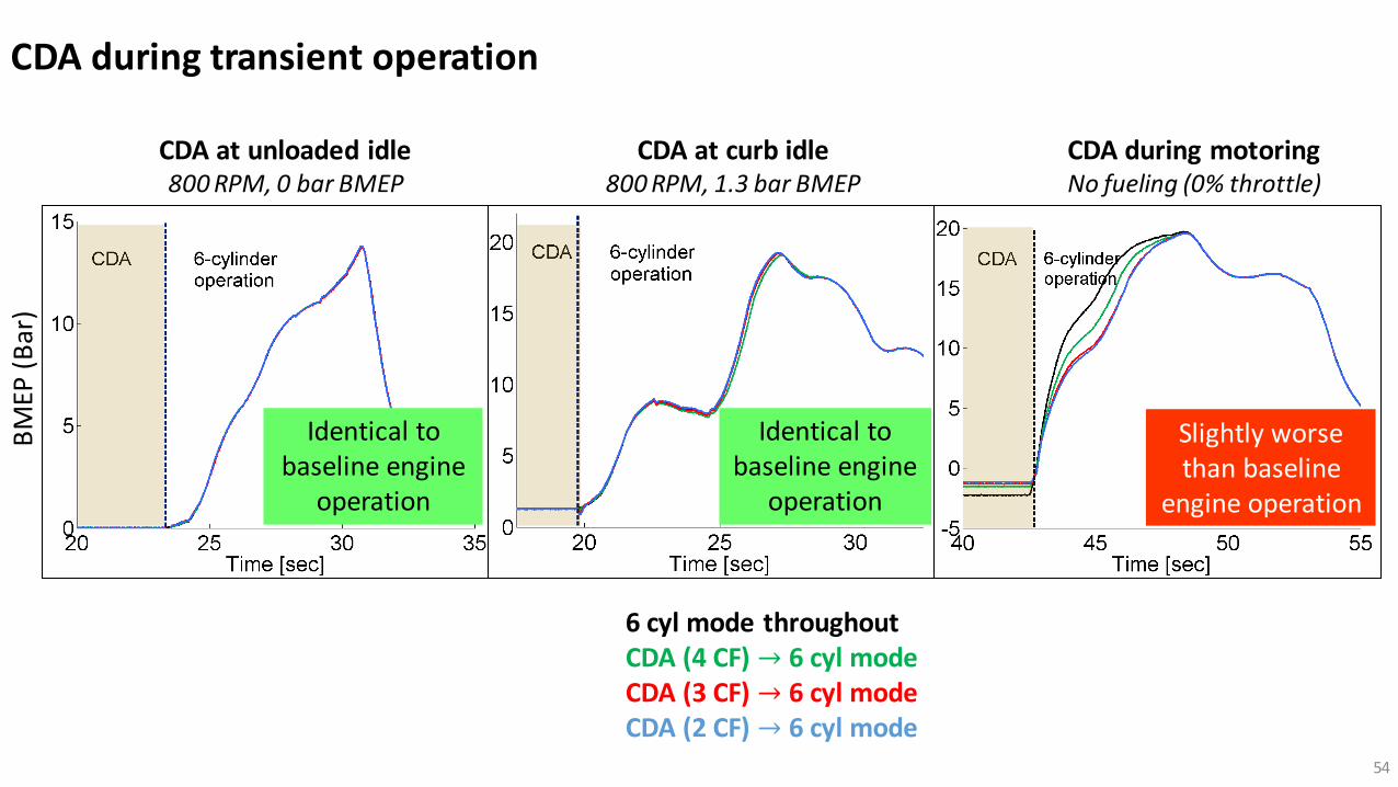
CDA during transient operation
CDA during transient operationB
MEP
(B
ar)
CDA at unloaded idle 800 RPM, 0 bar BMEP
CDA at curb idle 800 RPM, 1.3 bar BMEP
CDA during motoringNo fueling (0% throttle)
6 cyl mode throughout CDA (4 CF) → 6 cyl mode CDA (3 CF) → 6 cyl mode CDA (2 CF) → 6 cyl mode
Identical to baseline engine
operation
Identical to baseline engine
operation
Slightly worse than baseline
engine operation
54

CDA during transient operationB
MEP
(B
ar)
CDA at unloaded idle 800 RPM, 0 bar BMEP
CDA at curb idle 800 RPM, 1.3 bar BMEP
CDA during motoringNo fueling (0% throttle)
Slightly worse than baseline
engine operation
6 cyl mode throughout CDA (4 CF) → 6 cyl mode CDA (3 CF) → 6 cyl mode CDA (2 CF) → 6 cyl mode
Beg
inn
ing
of
acce
lera
tio
n
Identical to baseline engine
operation
Identical to baseline engine
operationBeg
inn
ing
of
acce
lera
tio
n
55

BTE Fuel-Efficient Stay-hot Get-hot
Open cycle ɳ Close cycle ɳ
Lower exhman press
Moreoptimal
heat release
Higher TOT via lower
heat loss
Higher TOT via lower
airflow
Lower exhflow i.e.
lower airflow
Higher exhflow i.e. higherairflow
rate
No HP EGR at
idle
HigherTOT via lower
heat loss
Less int-to-exh
gas exchange
1. Miller cycling2. Dynamic charging. .3. Cylinder deactivation4. Dynamic cylinder activation5. Non-fired cyl. ventilation 6. Cylinder cutout7. Reverse breathing 8. Intake rebreathing. . . . . . . . . . . . . 9. IVC modulation10. Internal EGR11. Early exhaust valve opening12. Late exhaust valve opening13. 2-stroke breathing + VVA14. High speed idle + VVA 15. Challenges with CDA?
- CDA during transient operation - Charge trapping study- Oil accumulation study - Vibration with CDA
Higher fuel flow
vialower OCE
Higher TOT via higher fuel flow
Higher fuel flow
vialower CCESummary
56
Potential to
eliminate elevated
exht. man.
pressure
VVA improves diesel engine fuel efficiency and aftertreatment thermal management.

BTE Fuel-Efficient Stay-hot Get-hot
Open cycle ɳ Close cycle ɳ
Lower exhman press
Moreoptimal
heat release
Higher TOT via lower
heat loss
Higher TOT via lower
airflow
Lower exhflow i.e.
lower airflow
Higher exhflow i.e. higherairflow
rate
No HP EGR at
idle
HigherTOT via lower
heat loss
Less int-to-exh
gas exchange
1. Miller cycling2. Dynamic charging. .3. Cylinder deactivation4. Dynamic cylinder activation5. Non-fired cyl. ventilation 6. Cylinder cutout7. Reverse breathing 8. Intake rebreathing. . . . . . . . . . . . . 9. IVC modulation10. Internal EGR11. Early exhaust valve opening12. Late exhaust valve opening13. 2-stroke breathing + VVA14. High speed idle + VVA 15. Challenges with CDA?
Higher fuel flow
vialower OCE
Higher TOT via higher fuel flow
Higher fuel flow
vialower CCESummary
57
Potential to
eliminate elevated
exht. man.
pressure
VVA improves diesel engine fuel efficiency and aftertreatment thermal management.

1. Miller cycling2. Dynamic charging. .3. Cylinder deactivation (CDA)4. Dynamic cylinder activation (DCA)5. Non-fired cyl. ventilation (NFCV)6. Cylinder cutout7. Reverse breathing 8. Intake rebreathing. . . . . . . . . . . . . 9. IVC modulation10. Internal EGR11. Early exhaust valve opening (EEVO)12. Late exhaust valve opening (LEVO)13. 2-stroke breathing + VVA. 14. High speed idle + VVA . . . . . . . . . 15. . . . . -100.0
0.0
100.0
200.0
300.0
400.0
500.0
600.0
700.0
800.0
900.0
500 1000 1500 2000 2500Engine Speed (RPM)
Load
(lb
-ft)
Zone 1 Zone 2
Zone 4
Zone 3
Zone 6
NT
E R
egio
n
• Miller cycling• Dynamic charging• IVC modulation
• Miller cycling• Dynamic charging• IVC modulation
• CDA• NFCV• DCA• Dynamic charging• IVC modulation
• CDA• NFCV• DCA
• LEVO• Miller cycling
Zone 5
Summary
Stay-Hot
Get-Hot
58
VVA improves diesel engine fuel efficiency and aftertreatment thermal management.

1. Miller cycling2. Dynamic charging. .3. Cylinder deactivation (CDA)4. Dynamic cylinder activation (DCA)5. Non-fired cyl. ventilation (NFCV)6. Cylinder cutout7. Reverse breathing 8. Intake rebreathing. . . . . . . . . . . . . 9. IVC modulation10. Internal EGR11. Early exhaust valve opening (EEVO)12. Late exhaust valve opening (LEVO)13. 2-stroke breathing + VVA. 14. High speed idle + VVA . . . . . . . . . 15. . . . . -100.0
0.0
100.0
200.0
300.0
400.0
500.0
600.0
700.0
800.0
900.0
500 1000 1500 2000 2500Engine Speed (RPM)
Load
(lb
-ft)
Zone 1 Zone 2
Zone 4
Zone 3
Zone 6
NT
E R
egio
n
• Miller cycling• Dynamic charging• IVC modulation
• Miller cycling• Dynamic charging• IVC modulation
• CDA• NFCV• DCA• Dynamic charging• IVC modulation
• CDA• NFCV• DCA
• LEVO• Miller cycling
Zone 5
Summary
Stay-Hot
Get-Hot
59
VVA improves diesel engine fuel efficiency and aftertreatment thermal management.

Brad Pietrzak
Ford
Lucius Wang
Faurecia
Leighton Roberts Eaton
Dr. ChuanDing
Mathworks
MayuraHalbe
Cummins
Sylvia LuMBA
Student
Soumya Nayyar
Cummins
Matt Van VoorhisRousch
Troy OdstrcilBoeing
Dr. Aswin RameshCummins
Dr. Dheeraj Gosala
Cummins
Dr. MrunalJoshi
Cummins
Dr. Alex TaylorBTMS
Dr. Kalen Vos
Sandia NL
Prof. Cody Allen
U. of Illinois
ShvetaDhamankar
John FosterDTNA
David Meyer
Technical Support
Ryan ThayerDr. Eric Holloway
Project Management
Greg Shaver
PI
Graduate Students
Purdue Team
60

© 2020 Eaton. All rights reserved..
Q & A

© 2020 Eaton. All rights reserved..
Engage the Experts: free webinars on commercial vehicle engine strategies
September 9 The truth about diesel CDA and NVHTom Reinhart, Southwest Research Institute (SwRI)
September 30 Achieving 2027 emissions regulationsChris Sharp, Southwest Research Institute (SwRI)
October 14 The advantages of CDA over real-world drive cyclesDr. Mrunal Joshi, Cummins
October 21 Understanding diesel cylinder deactivationDr. Greg Shaver, Purdue University
October 28 CDA versus cylinder cutout: a technology overview Dr. Cody Allen, University of Illinois

© 2020 Eaton. All rights reserved..