Embed Size (px)
Citation preview

EN
ER
GY
SO
LV0
1-
02
T-1
26
25
Ver.01
DIFFERENTIAL TEMPERATURE CONTROLLER FOR SOLAR HEATING SYSTEMS WITH 4 SENSORS
AND 4 CONFIGURABLE OUTPUTS
1 - DESCRIPTIONEnergySol plus is a differential temperature controller for solar heating systems with four temperature sensors and four relay outputs, which performs the control and management of all kinds of facilities, including booster systems (gas or electric heating.) This controller has functions that prevents the overheating and freezing of the water in the pipes of the collectors and operates in the water circulation of the pump control through the temperature differential between solar collectors and thermal storage tank (or swimming pool).EnergySol plus provides the user with a quick configuration of its functions through its wide range of predefined layouts and a friendly interface. According to the application you can select one out of 9 layouts (or types of installation) predefined in the controller or freely use the available functions by configuring it in a customized manner.
2 - APPLICATIONSolar heating systems aided by a pump.
3 - TECHNICAL SPECIFICATIONS- Power supply: 90 to 264Vac (50/60Hz)- Temperature control: S1, S3 and S4: -50 to 200°C / -58 to 392°F (using sensor SB59) S2: -50 to 105°C / -58 to 221°F- Resolution: 0.1°C between -10 and 100°C and 1°C in the remainder of the band 1 °F the all of the range- Inputs:Four temperature sensors: S1 - temperature sensor 1
S2 - temperature sensor 2S3 - temperature sensor 3 S4 - temperature sensor 4 (sensor sold separately)
- Outputs:Four relay outputs: RL1 - Operation of the pump
Maximum current 5(3)A/240Vac 1/8HPContact NO
RL2 - Auxiliary operation 1Maximum current 5(3)A/240Vac 1/8HPContact NO
RL3 - Auxiliary operation 2Maximum current 5(3)A/240Vac 1/8HPContact NO
RL4 - Auxiliary operation 3Maximum current 5(3)A/240Vac 1/8HPContact NO
- Dimensions (WxHxD): 90 x 130 x 43mm. - Operating Temperature of the controller: 0 to 50°C- Operating humidity: 10 to 90% RH (no condensation)
www.fullgauge.comMADE IN BRAZIL
1 2
3
4
5
6
7
8
9 10 11 12 13 14 15 16 17 18
4 - IDENTIFICATION OF THE PARTS OF THE ONTROLLER'S
PARTS
4.1 - Identification of the terminalsEnergySol plusdrawing below.
has two sets of terminals located in the rear of the controller, as shown in the
The temperature sensor inputs and the communicationconnections with SITRAD are located in the verticalterminals.
Relay outputs and power supply of the located in the horizontal connectors
controller are
AB Serial
CommunicationRS-485
Sensor S1
Sensor S2
Sensor S3
Sensor S4
LO
AD
1
Mai
n
Su
pp
ly (
*)
(*) For the model EnergySol plus:17 = 90 to 264Vac,18 = 0 Vac
For the model EnergySol L plus:17 = 12 Vac/Vdc,18 = 0 Vac/Vdc
2L
OA
D 3
LO
AD
4L
OA
D
RL1 RL2 RL3 RL4
4.2 - Identification of the front panelEnergySol plus features a liquid crystal display as a visual interface with the user on the front panel and four navigation keys, as shown in the figure below.
and : These keys are used to work through the menus and functions of the controller. When the user is
adjusting a certain function, the key decreases and
increases the value of that function.
: If the user is viewing the main screen andpresses this key, the display will show the easy access functions. When the menu or sub-menu is being viewed, the controller returns to the main screen or the next highest menu.
: This is used to enter in a menu or function. By adjusting a function this key is to confirm a new value.
Menu
OK
Full GaugeControls
Full GaugeControls
5 - HOW TO ACCESS THE MENUSEnergySol plus plus has all its programming separated into menus as shown below: To access the
menus on the controller, press and simultaneously for 2 seconds.You will then see the 01-Access Code screen showing the value 000 .
06-Config
07-Descriptions
08-Layout
05-Clock
02-Functions
03-Parameters
04-Schedule
01-Access Code
5.1 - Access CodeThe menu 01-Access Code is used to enter a security code to allow access to certain programs.
123 : Allows functions, parameters, scheduler, clock and configurations to be changed.
231: Allows unit of measurement to be changed (°C/°F).
717 : Allows the layout of the installation to be selected.

5.2 - Functions menu The functions form a group of adjustments for a given application, e.g.: control setpoints, hysteresis, functions associated to each output, etc. On the table below are shown all the EnergySol plus available functions
DescriptionFunTemperature hysteresis to turn on the circulation pump Temperature hysteresis to turn off the circulation pumpSolar collector minimum temperature to activate the pump Pump restart delay Negative Hysteresis to activate the solar collector pump to dissipate heat Hysteresis to turn off the pump on heat-sink function Minimum temperature to enable the pump to act as heat-sinkSolar collector antifreeze temperature to activate the pumpAntifreeze hysteresis temperature Antifreeze pump minimum activation time Solar collector overheat temperature to deactivate the circulation pump Solar collector overheat temperature hysteresis of the circulation pump Storage tank overheat temperature to deactivate the circulation pump Storage tank overheat temperature hysteresis to re-conect the circulation pump Sensor S3 position Sensor S4 position Relay RL2 functionRelay RL3 functionRelay RL4 functionDifference between S2 and S3 to alternate storage tanks (if S3=tank 2) Maximum time to exchange the storage tank (if F20 does not occur) Operational priority between storage tanksS2 temperature setpoint to turn off the auxiliary heating
F01F02F03F04F05F06F07F08F09F10F11F12F13F14F15F16F17F18F19F20F21F22F23
Min. Max.
Celsius Fahrenheit
Unit1.11.0
-50.00
-40.01.00.0-211.00
0.01.00.01.000000
1.010
-50.0
40.039.9200.09990.040.0105.010.020.0999
200.020.0105.020.0
42533
50.01440
2105.0
8.04.0
-50.00
0.05.0
105.08.05.00
90.01.0
105.01.00000010300
15.0
147
-58009
2214690
1941
2211000001830059
°F°F°F
Sec.°F°F°F°F°F
Sec.°F°F°F°F-----
°FMin.
-°F
°C°C°C
Sec.°C°C°C°C°C
Sec.°C°C°C°C-----
°CMin.
-°C
Standard11
-580
-72132-51032132100000110
-58
7272392999072221503699939236221364253390
14402
221
Min. Max. Unit Standard
S3 temperature Setpoint to turn off the auxiliary heatingTemperature hysteresis reactivate the auxiliary heatingTime to reach Setpoint (F23 or F24) before turning on 2nd boosterS2 temperature setpoint to activate the heat sink S3 temperature setpoint to activate the heat sink Temperature hysteresis to stop auxiliary heating Booster RL2 and RL3 operating mode Setpoint to activate the circulation of water in the main water lineTemperature hysteresis to disable the circulation of water in the main water lineMinimum time of the water circulation in the main water lineMaximum time of the water circulation in the main water lineMinimum time between operations involving water circulation in the main water line Output RL2 alternative functionOutput RL3 alternative functionOutput RL4 alternative function RL1 circulation pump operating modeRL2 circulation pump operating modeChoice of sensors for the temperature differential
F24F25F26F27F28F29F30F31F32F33F34F35F36F37F38F39F40F41
-50.01.01
-50.0-50.01.00
-50.01.0111000000
15.01.030
45.045.01.02
25.01.011010000000
591301131131277111010000000
°F°F
Min. °F°F°F-
°F°F
Min.Min.Min.
------
°C°C
Min.°C°C°C-
°C°C
Min.Min.Min.
------
-5811
-58-5810
-581111000000
200.020.01440105.0200.020.0
2200.020.0144014401440
111221
39236
1440221392362
39236
144014401440
111221
F01 - Temperature hysteresis to turn on the circulation pump Allows for the setting of the temperature difference between the collector and the storage tank to operate the circulation pump. If the difference is greater than or equal to the value set in this function the pump is turned on.
F02 - Temperature hysteresis to turn off the circulation pump Allows for the setting the temperature difference between the collector and the storage tank to turn off the circulation pump. If the difference is less than the value set in this function the pump is turned off.
F03 - Solar collector minimum temperature to activate the pump Allows for the setting of the minimum temperature in the collector sensor to operate the circulation pump. Besides the temperature difference between the collector and storage tank, it is necessary that the collector temperature is greater than or equal to the value set in this position for the pump to be connected.
F04 - Pump restart delay This function sets the minimum time that the circulation pump should be switched off before being activated again.
F05 - Negative Hysteresis to activate the solar collector pump to dissipate heat When the temperature in the storage tank is greater than the temperature in the collector, the difference between the collector and the storage tank will be negative. If this difference is less than the value set for this function the collector circulation pump will be turned on to dissipate the heat. To disable this function, increase the value until “Off’’ is shown in the display.
F06 - Hysteresis to turn off the pump on heat-sink function When the temperature of the storage tank decreases in such a way that the negative differential goes below the value set for this function, the pump is deactivated as a heat-sink.
F07 -Minimum temperature to enable the pump to act as heat-sinkFor security, in this function the operator sets the value of the minimum temperature of sensor S2 to allow the pump to be activated to dissipate heat.
F08 - Solar collector antifreeze temperature to activate the pumpThis function sets a temperature value to prevent the collectors from freezing (in cold regions). When the temperature sensor of the collector is below this value, the circulation pump of the collector is activated. To deactivate the anti-freeze function, simply decrease the value until the message “Off’’ appears in the display.
F09 - Antifreeze hysteresis temperature This is the difference in temperature of the collector sensor to turn off the antifreeze mode. When the antifreeze mode is activated, the pump will be activated until the temperature sensor of the collector reaches the value of F08+F09.
F10 - Antifreeze pump minimum activation time This is the minimum time for the pump to be connected with safety to ensure that the water flows in all collectors.
F11 - Solar collector overheat temperature to deactivate the circulation pump This is the maximum temperature in the collector above the temperature where the circulation pump can no longer operate. This is a security measure to protect the hydraulic system in cases of overheating.
F12 - Solar collector overheat temperature hysteresis of the circulation pump This is the temperature difference that the collector should be showing, after reaching the overheating temperature, so that the circulation pump can be activated again.
F13 - Storage tank overheat temperature to deactivate the circulation pump This is the maximum desired temperature in the storage tank, above which the collector circulation pump cannot operate. This is a security measure to protect the hydraulic system in cases of overheating.
F14 - Overheating temperature hysteresis of the storage tank to re-connect the circulationpumpThis is the temperature difference that the storage tank should show, after reaching the overheating temperature, so that the circulation pump can be activated again.
F15 - Position of sensor S3Allows the choice of the location where the sensor S3 will be installed
Unused - Not usedReservoir 1 - Storage tank 1Reservoir 2 - Storage tank 2Sol. Pan. 2 - Collector 2Water Circ. - Main water line
F16 - Position of sensor S4Allows the choice of the location where the sensor S4 will be installed
Unused - Not usedSol. Pan- Input to the CollectorWater Circ. - Main water line
F17 - Relay RL2 functionChoice of the function of the output relay RL2
Unused - NoneHeating - Heating by gas or a heating elementPanel selec - 2 stage valve for selection of the collectorPan 2 circ - Circulation pump for the collector 2Reservoir 2 - Circulation pump for storage tank 2Cyclic - The output is turned on and off respecting the time in P03 and P04
F18 - Relay RL3 functionChoice of the function of the output relay RL3
Unused - NoneHeating - Heating by gas or a heating elementHeat Dis. - Heat sinkCyclic - The output is turned on and off respecting the time in P05 and P06

F19 - Relay RL4 functionAllows the choice of the function for the output relay RL4
Unused - NoneHeating - Heating by gas or a heating element of storage tank 2Water Circ. - Main water lineCyclic - The output is turned on and off in time respecting the P07 and P08
F20 - Difference between S2 and S3 to alternate storage tanks (if S3=tank 2) This function is used in applications where two separate storage tanks are used separately with a single common collector. The selection between the two storage tanks is made with a pump for each of them (as in layout 6). The value set in this function represents the maximum temperature difference between the two storage tanks. When the temperature in storage tank 1 is higher than in storage tank 2, and this difference is greater than the value set in this function, the EnergySol plus turn off the storage tank 1 pump and turn on the storage tank 2 pump.
F21 - Maximum time to exchange the storage tank (if F20 does not occur) In systems with two storage tanks this function determines the maximum operating time for each storage tank if the temperature difference between them does not reach the value set in F20.
F22 - Operational priority between storage tanksIf the system operates with two storage tanks, this function sets which tank has the heating precedence. Thus, the storage tank with the lower priority will be heated only when the selected storage tanks is already within the set temperature range, and will have the heating stopped if the selected tanks requires heating. In the automatic mode the two storage tanks are heated in an alternate way, based on the temperature and time settings of the functions F20 and F21.
Auto - The use of collector PCB for each tank will be alternated for each tank, adhering to the settings of F21 and F22.
Reservoir 1 - The storage tanks connected to relay RL1 will have priorityReservoir 2 - The storage tanks connected to relay RL2 will have priority
F23 - S2 temperature setpoint to turn off the auxiliary heating This is the temperature measured by sensor S2 that the auxiliary heating will be turned off
F24 - S3 temperature Setpoint to turn off the auxiliary heatingThis is the temperature measured by sensor S3 that the auxiliary heating will be turned off
F25 - Temperature hysteresis reactivate the auxiliary heatingThis is the temperature difference to reconnect the auxiliary heating after reaching the Setpoint.
F26 - Time to reach the Setpoint (F23 or F24) before starting the 2nd boosterSets the maximum time to reach the auxiliary heating Setpoint before turning on the second booster.
F27 - S2 temperature setpoint to activate the heat sink Sets the S2 temperature above that where the heat sink is operated.
F28 - S3 temperature setpoint to activate the heat sink Sets the S3 temperature above that where the heat sink is operated.
F29 - Temperature hysteresis to stop auxiliary heating It is the temperature differential in S2 and S3 to stop using the heat sink.
F30 - Operation mode of boosters RL2 and RL3RL2 First - Booster RL2 will operate firstRL3 First - Booster RL3 will operate firstTogether - Both boosters act together
If F36 and/or F37 were configured as "Schedule", each relay will need to have an event registered in the SCHEDULER, or be manually activated to become operational.
F31 - Setpoint to activate the circulation of water in the main water lineIn systems using recirculation of the main water line this function sets the Setpoint temperature of the outlet water for use. If this is below the value set for this function, the controller activates the circulation pump of the main water line.
F32 - Hysteresis for disabling the water circulation in the main water lineIn systems that use recirculation of the main water line, this function is the temperature differential at the output for use needed to turn off the main water line pump. If the temperature is greater than F31 plus the value set for this function, the pump will be disconnected.
F33 - Minimum time of the water circulation in the main water lineIn systems using the recirculation of the main water line this function sets the minimum time that the water circulation pump in the main water line will be operational. Even though the temperature in the main water line has already reached the temperature to stop the pump, it will remain connected for the remaining time to complete the minimum set time.
F34 - Maximum time of the water circulation in the main water lineIn systems using the recirculation of the main water line this function sets the maximum time that the water will be circulating in the main water line. If the operating time of the pump exceeds the value set for this function, the pump is turned off. This occurs even though the required temperature has not been reached.
F35 - Minimum time between circulation water operations in the main water lineIn recirculation systems using the main water line this function sets the minimum stopped time of the main water line pump before being operated again.
F36 - Output RL2 alternative function Regular - Activation in accordance with the functions related to RL2.Schedule - Allows the operation according to the functions only when there is an active
event set in the events Scheduler of RL2.
F37 - Output RL3 alternative function Regular - Activation in accordance with the functions related to RL3.Schedule - Allows the operation according to the functions only when there is an active event
set in the events scheduler of RL3.
F38 - Output RL4 alternative function Regular - Activation in accordance with the functions related to RL4.Schedule - Allows the operation according to the functions only when there is an active event
set in the events scheduler of RL4.F39 - RL1 circulation pump operating modeFor normal use of the device, this function is set to Automatic control and the circulation pump is activated while respecting the values set in the functions. If this function is set to Off or On, the functions related to the pump will be ignored and the pump will remain in this state until this function is changed to automatic control again.Auto - Automatic Control
off - Circulation pump is always off
on - Circulation pump always on
F40 - RL2 circulation pump operating modeThis function is only used if the relay RL2 is used as the circulation pump of a second collector. In this case, this function is similar to F39. The two pumps cannot be operated simultaneously. To avoid this situation, the option On is available only when another pump is set to Off. If one of the pumps is set to On, the other pump will not allow that it is set to Automatic control.Auto - Automatic Control
off - Circulation pump is always off
on - Circulation pump always on
F41 - Choose the sensors for the temperature differentialWhen the sensor S3 is used with the same storage tank as sensor S2, this function allows you to choose which of the two sensors will be used to calculate the temperature differential to activate the pump.
S1-S2 - The pump will be activated by the temperature difference of sensors S1 and S2
S1-S3 -The pump will be activated by the temperature difference of sensors S2 and S3
5.3 - - Parameters menuThese are the system parameter settings. Among them are: offset of each sensor, alarms, and parameters for the cyclic timers.
FunMinimum temperature alarm for S1Maximum temperature alarm for S1Time that the cyclic timer is connected (RL2)Time that the cyclic timer is disconnected (RL2)Time that the cyclic timer is connected (RL3)Time that the cyclic timer is disconnected (RL3)Time that the cyclic timer is connected (RL4)Time that the cyclic timer is disconnected (RL4)Minimum allowable value to set F23 and F27Maximum amount allowed to set F23 and F27Minimum allowable value to set F24 and F28Maximum allowable value to set F24 and F28Minimum allowable value to set F31Maximum allowable value to set F31Time of manual operation of output RL2Time of manual operation of output RL3Time of manual operation of output RL4Density of the heated liquid in the collectorSpecific heat of the heated fluid in the collectorPump flow rateTemperature offset of sensor S1Temperature offset of sensor S2Temperature offset of sensor S3Temperature offset of sensor S4
P01P02P03P04P05P06P07P08P09P10P11P12P13P14P15P16P17P18P19P20P21P22P23P24
Celsius Fahrenheit
-50.0-50.0
111111
-50.0-50.0-50.0-50.0-50.0-50.0
0001110
-5.0-5.0-5.0-5.0
200.0200.0999999999999999999
105.0105.0200.0200.0200.0200.09999999995000500060000
5.05.05.05.0
-50.0200.0
111111
-50.0105.0-50.0200.0-50.0200.0
000
99741805000.00.00.00.0
-58-58
111111
-58-58-58-58-58-580001110-9-9-9-9
3923929999999999999999992212213923923923929999999995000500060000
9999
-58392111111
-58221-58392-58392000
99741805000000
°F°F
min.min.min.min.min.min.°F°F°F°F°F°F
min.min.min.
kg/m³J/kg.K
L/h°F°F°F°F
°C°C
min.min.min.min.min.min.°C°C°C°C°C°C
min.min.min.
kg/m³J/kg.K
L/h°C°C°C°C
Description Min. Max. Unit Standard Min. Max. Unit Standard

WaterPropylene Glycol Solution 40%Propylene Glycol Solution 50%
Density
4186 J/Kg.K3621 J/Kg.K3559 J/Kg.K
Liquid
WaterPropylene Glycol Solution 40%Propylene Glycol Solution 50%
Density
997 Kg/m31030 Kg/m1036 Kg/m3
Liquid
P01 - Minimum temperature alarm for S1If the temperature of sensor S1 is below the value set in this parameter, the controller will show on the display a message relating to this alarm. The audible alarm will also be operated, if the buzzer is enabled.
P02 - Maximum temperature alarm for S1If the temperature sensor S1 is above the value set for this parameter, the controller will show on the display a message relating to this alarm. The audible alarm will also be operated, if the buzzer is enabled.
P03 - Time that the cyclic timer will be connected (RL2)When the relay RL2 is cyclic, it will use the ON time as the value set in this parameter.
P04 - Time that the cyclic timer is disconnected (RL2)When the relay RL2 is cyclic, it will use the OFF time as the value set in this parameter.
P05 - Time that the cyclic timer is connected (RL3)When the relay RL3 is cyclant, it will use the ON time as the value set in this parameter.
P06 - Time that the cyclic timer is disconnected (RL3)When the relay RL3 is cyclant, it will use the OFF time as the value set in this parameter.
P07 - Time that the cyclic timer is connected (RL4)When the relay RL4 is cyclant, it will use the ON time as the value set in this parameter.
P08 - Time that the cyclic timer is disconnected (RL4)When the relay RL4 is cyclant, it will use the OFF time as the value set in this parameter.
P09 - Minimum allowable value to set F23 and F27Parameterizes the minimum value allowed for the adjustment of functions F23 and F27. These functions adjust the temperature Setpoints in S2.
P10 - Maximum amount allowed to set F23 and F27Parameterizes the minimum value allowed for the adjustment of functions F23 and F27. These functions adjust the temperature Setpoints in S2.
P11 - Minimum allowable value to set F24 and F28Parameterizes the minimum value allowed for the adjustment of functions F23 and F27. These functions adjust the average temperature Setpoints in S3.
P12 - Maximum allowable value to set F24 and F28Parameterizes the maximum value allowed for the adjustment of functions F23 and F27. These functions adjust the average temperature Setpoints in S3.
P13 - Minimum allowable value to set F31Parameterizes the minimum value allowed for the adjustment of the F31 function, which adjusts the Setpoint for the temperature control of the main water line.P14 - Maximum allowable value to set F31Parameterizes the minimum value allowed for the adjustment of the F31 function, which adjusts the Setpoint for the temperature control of the main water line.
P15 - Time for the manual operation of output RL2Parameterizes the running time of RL2 output when operated manually. To manually operate the RL2 output, use the easy access features.
P16 - Time for the manual operation of output RL3Parameterizes the running time of RL3 output when operated manually. To manually operate the RL3 output, use the easy access features.
P17 - Time of manual operation of output RL4Parameterizes the running time of RL4 output when operated manually. To manually operate the RL4 output, use the easy access features.
P18 - Density of the heated liquid in the collectorUsing the value of this parameter, EnergySol plus carries out the calculations relating to the energy meter. With the energy meter (built-in feature of the controller) it is possible to measure the amount of energy absorbed by the solar heating system.
P19 - Specific heat of the heated fluid in the collectorUsing the value of this parameter, EnergySol plus carries out the calculations relating to the energy meter. With the energy meter (built-in feature of the controller) it is possible to measure the amount of energy absorbed by the solar heating system.
P20 - Pump flow rateUsing the value of this parameter, EnergySol plus carries out the calculations relating to the energy meter. With the energy meter (built-in feature of the controller) it is possible to measure the amount of energy absorbed by the solar heating system.If the selected temperature unit is Celsius, the unit will be used for flow L / h (liters per hour). If you select the temperature units Fahrenheit, the unit will be flow used GPH (gallon per hour).For transform the unit of l / m (liter per minute) to L / h (liters per minute), simply multiply the value by 60. Of the same can be obtained off the value of GPM (gallon per minute) for GPH (gallon per hour).Ex L 1 / L = 60 m / h1 GPM = 60 GPH
P21 - Temperature offset of sensor S1With this parameter it is possible to make small offset corrections in the reading of temperature sensor S1.
P22 - Temperature offset of sensor S2With this parameter it is possible to make small offset corrections in the reading of temperature sensor S2.
P23 - Temperature offset of sensor S3With this parameter it is possible to make small offset corrections in the reading of temperature sensor S3.
P24 - Temperature offset of sensor S4With this parameter it is possible to make small offset corrections in the reading of temperature sensor S4.
5.4 - Scheduler Menu Each of the outputs RL2, RL3 and RL4 has a schedule of events and can be configured to operate only as long as there is an active event. When you enter the Scheduler menu, the user must first of all configure the operating mode of the scheduler, then set up the events.
Operation mode of the RL2 scheduler:Operation mode of the RL3 scheduler:Operation mode of the RL4 scheduler:
Weekly: Weekly Programming - In this mode the instrument can configure up to 4 different events for each day of the week.Work Days: Weekdays Programming - In this mode, the instrument keeps the same events from weekdays (Monday to Friday) and allows you to program different events for Saturday and Sunday.Daily : Daily Programming - In this mode, the instrument keeps the same events for all days of the week
Programing of the RL2 scheduler:Programing of the RL3 scheduler:Programing of the RL4 scheduler:
The programming of the scheduler is done by setting up the start time and end time of each event. The total number of events depends on the operating mode selected for each schedule. If the Daily mode is selected, when programming the event, the screen will show "Sun. thru Sat." indicating that the event will be repeated daily (every day of the week). In this mode four events can be set up
In the Weekly mode, the event time for each day of the week should be set up, thus allowing the event to occur every day at distinct times or occur only on certain days of the week. The display will show the day of the week corresponding to the event.
An event can be configured to start on one day and end in another. To do this, an event start time must be set up and the end time must be increased until the "cross" are visible. Therefore a second event must be set up with the initial time set to "00:00" and the end time of the event. To turn an event off, simply increase the off time until "off" is visible.
.
RL2 Sched Evt
RL2 Sched Mode
04-Schedule
RL2 Sched ModeA01@ Daily
Sun. thru Sat.E01@ 08:00/10:00Sun. thru Sat.E02@ 10:00/12:00Sun. thru Sat.E03@ 12:00/14:00Sun. thru Sat.E04@ 14:00/16:00
5.5 - Clock Setting MenuIn the clock set-up menu the clock time and day of the week can be set up. When accessing the menu the current time and the day of week will be displayed with the hour digits flashing. Using the keys
and you can change this value and the key to confirm the new value.
With each setting, the next field will flash indicating that it can be changed. The values that are set are the hours, minutes, seconds and day of the week. By confirming the day week, the clock setting is complete.If the driver is off for a long time, the clock may lose its settings due to the low internal battery level that keeps it in operation. In this case the "set clock" message will be displayed. If the clock is not set, the events that are set in the scheduler will not run. To get the controller to return to its normal operation, the clock must be set correctly. To fully recharge the battery, the controller needs to be energized for around 10 hours.
5.6 - Settings MenuIn the settings menu the user can adjust the display, enable the audible beep, set the language and address on the RS-485 network.
OK
05-Clock 17:00:00 Sex
C01- Preferential indicationAllows the choice of the content to be displayed on the main screen:
Sensor 1 - S1 TemperatureSensor 2 - S2 TemperatureSensor 3 - S3 TemperatureSensor 4 - S4 TemperatureDiffer. - Differential temperature of controlAll - Temperatures S1, S2, S3 and S4Outs - State of RelaysClock - Day and timeEnergy - Energy MeterRotate - Switch between temperature, differential temperature and state of the outputs
C02 - LCD ContrastAllows the display contrast to be adjusted.
FunPreferential indicationLCD ContrastLCD backlight intensity Timer OffBuzzer OnLanguageAddress on the RS-485 network
C01C02C03C04C05C06C07
Description Min. Max. Unit Standard
0000001
994
144012
247
1535001
---
Min.---

C03 - Backlight intensityAllows the display illumination intensity to be adjusted.
C04 - Time OffAllows the time maximum that the display can be shown when the controller is inactive.
C05 - Buzzer OnAllows the buzzer to be enabled.
off - Buzzer disabled
on - Buzzer enabled
C06 - LanguageSelects the display language.
Portugues - Portuguese
English - English
Espanol - Spanish
C07 - Address on the RS-485 networkAllows the 485 network address of the controller to be set up.
5.7 - Adjustment Menu of the descriptionsAllows the adjustment of the messages from the sensors used by EnergySol plus from a list. The selected message will be used on the main screen of the unit. This adjustment allows the user to identify, in a easier manner, where each sensor is positioned. It should be noted that the descriptions do not interfere with the operation of the equipment; therefore they should be set up according to the installation.
Description of sensor 1
Description of sensor 2
Description of sensor 3
1 S1 Description-
2-S2 Description
3-S3 Description
Description of sensor 44-S4 Description
5.8 - Selection of the Layout EnergySol plus allows the user to quickly set up its functions making use of predefined layouts. According to the application it is possible to select one of the nine topologies shown in this manual, or configure the controller in a customized manner. These layouts are intended to simplify the setting of EnergySol plus, pre-setting some functions and not showing the functions that are not relevant to the application of such a layout.
To change the layout, access the menu “01-Access Code” e insira o código 717.
The screen for selecting the layout will then be shown. To change the layout, use the and
keys until the required option is shown. The key confirms the selection, and the key
cancels it. When changing this, the functions menu is populated with default values from the selected layout.
The table below shows the main features of each layout.
OK
Menu
Layout Layout 1
Layout Layout 2
Layout Layout 3
Layout Custom
5.8.1 - Layout 1This layout uses the temperature differential between the sensors S1 and S2 to control the circulation pump through relay RL1. Other sensors and outputs are disabled.
Collector
PumpRL1
Storage tank
°C
S4*
°C
S2
°C
S1
When the temperature difference between the sensors S1 and S2 reaches the value set in F01, the circulation pump (RL1) is operated. The water travels through the collector heating the water in the tank. The temperature difference gradually decreases, and when it reaches the value set in F02, the pump is turned off.
*The sensor S4 can be used to estimate the solar energy absorbed by the system. This value is indicative of the amount of energy saved by using solar power rather than electrical system, for example. The absorbed solar energy calculation is activated through the easy access menu.
These functions use the default values shown in the table according to the layout chosen.These are not displayed by the controller and they cannot be edited
FunTemperature hysteresis to turn on the circulation pump Temperature hysteresis to turn off the circulation pump Solar collector minimum temperature to activate the pump Pump restart delay Negative Hysteresis to activate the solar collector pump to dissipate heat Hysteresis to turn off the pump on heat-sink function Minimum temperature to enable the pump to act as heat-sinkSolar collector antifreeze temperature to activate the pumpAntifreeze hysteresis temperature Antifreeze pump minimum activation time Solar collector overheat temperature to deactivate the circulation pump Solar collector overheat temperature hysteresis of the circulation pump Storage tank overheat temperature to deactivate the circulation pump Storage tank overheat temperature hysteresis to re-connect the circulation pump Position of sensor S3Sensor S4 position Relay RL2 functionRelay RL3 functionRelay RL4 functionRL1 circulation pump operating mode
F01F02F03F04F05F06F07F08F09F10F11F12F13F14F15F16F17F18F19F39
Celsius Fahrenheit
1.11.0
-50.00
-40.01.00.0
-21.01.00
0.01.00.01.0-----0
40.039.9200.09990.040.0105.010.020.0999
200.020.0105.020.0
-----2
8.04.0
-50.00
0.05.0
105.08.05.00
90.01.0
105.01.0000000
11
-580
-72132-510321321-----0
727239299907222150369993923622136-----2
147
-58009
2214690
1941
2211000000
°F°F°F
Sec.°F°F°F°F°F
Sec.°F°F°F°F------
°C°C°C
Sec.°C°C°C°C°C
Sec.°C°C°C°C------
5.8.1.1 - Table of parameters used in Layout 1
Description Min. Max. Unit Standard Min. Max. Unit Standard

5.8.2 - Layout 2This layout uses the temperature differential between the sensors S1 and S2 to control the circulation pump through relay RL1. The temperature sensor S3, also in the storage tank is used to operate the gas booster via relay RL2. If there is a shortage of gas, the heating element connected to relay RL3 is activated (the lack of gas is identified by the time taken without reaching the Setpoint).
When the temperature difference between the sensors S1 and S2 is above the value set in F01, the circulation pump (RL1) is operated. The water travels through the collector heating the water in the tank. The temperature difference gradually decreases, and when it reaches the value set in F02, the pump is turned off.During the time set in the events scheduler, if the temperature measured by sensor S3 is less than the value set in F24, the relay RL2 is operated as heating until the S3 temperature reaches the temperature of F24. If the temperature does not reach the Setpoint in time set in F26, the relay RL3 is operated as a second booster. When connecting the second booster, the first will be turned off.For this operational logic to work automatically, it must be configured in the event schedulers of relays RL2 and RL3.If the event is set up in only one of the schedulers, only the relay that has the event set up will be operational. If the event is set up only in the RL2 scheduler, it will become operational at the beginning of the event and if the temperature does not reach the Setpoint value set within the set time in F26, it will be turned off. If the RL3 scheduler is set, on its own, the RL3 come into operation only after the time set in F26.The booster heaters can also be operated through the easy access menu. In this case, the operation will be identical to the operation when set in the event scheduler. The duration of the manual operation of each relay is set in P15 and P16.
Sensor S4 can be used to estimate the solar energy absorbed by the system. This value is an indication of the amount of energy saved by using solar power rather than an electrical system, for example. The absorbed solar energy calculation is activated through the easy access menu.
Collector
PumpRL1
Storage tank
°C
S4*°C
S2
°C
S1
°C
S3 ResistRL3
GasRL2
FunTemperature hysteresis to turn on the circulation pump Temperature hysteresis to turn off the circulation pump Solar collector minimum temperature to activate the pump Pump restart delay Negative Hysteresis to activate the solar collector pump to dissipate heat Hysteresis to turn off the pump on heat-sink function Minimum temperature to enable the pump to act as heat-sinkSolar collector antifreeze temperature to activate the pumpAntifreeze hysteresis temperature Antifreeze pump minimum activation time Solar collector overheat temperature to deactivate the circulation pump Solar collector overheat temperature hysteresis of the circulation pump Storage tank overheat temperature to deactivate the circulation pump Storage tank overheat temperature hysteresis to re-connect the circulation pump Position of sensor S3Sensor S4 position Relay RL2 functionRelay RL3 functionRelay RL4 functionS3 temperature Setpoint to turn off the auxiliary heating
F01F02F03F04F05F06F07F08F09F10F11F12F13F14F15F16F17F18F19F24
Celsius Fahrenheit5.8.2.1 - Table of parameters used in Layout 2
Temperature hysteresis reactivate the auxiliary heatingTime to reach Setpoint (F23 or F24) before turning on 2nd boosterOperating mode of booster RL2 and RL3Output RL2 alternative function Output RL3 alternative function RL1 circulation pump operating modeChoice of sensors for the temperature differential
F25F26F30F36F37F39F41
These functions use the default values shown in the table according to the layout chosen.These are not displayed by the controller and they cannot be edited
Description
1.11.0
-50.00
-40.01.00.0
-21.01.00
0.01.00.01.0-----
-50.0
40.039.9200.09990.040.0105.010.020.0999
200.020.0105.020.0
-----
200.0
8.04.0
-50.00
0.05.0
105.08.05.00
90.01.0
105.01.010110
15.0
11
-580
-72132-510321321-----
-58
727239299907222150369993923622136-----
392
°F°F°F
Sec.°F°F°F°F°F
Sec.°F°F°F°F-----
°F
°C°C°C
Sec.°C°C°C°C°C
Sec.°C°C°C°C-----
°C
147
-58009
2214690
1941
22111011059
1.01---0-
20.01440
---2-
1.03001100
11---0-
361440
---2-
°FMin.
-----
°CMin.
-----
13001100
Min. Max. Unit Standard Min. Max. Unit Standard
5.8.3 - Layout 3This layout uses the temperature differential between the sensors S1 and S2 to control the circulation pump through relay RL1.The temperature sensor S3, also in the storage tank is used to operate the booster heating (RL2) and the heat sink (RL3).
When the temperature difference between the sensors S1 and S2 is above the value set in F01, the circulation pump (RL1) is operated.The water travels through the collector heating the water in the tank. The temperature difference gradually decreases, and when it reaches the value set in F02, the pump is turned off.During the time set in the events scheduler, if the temperature measured by sensor S3 is less than the value set in F24, the relay RL2 is operated as booster heating until the S3 temperature reaches the temperature of F24. The booster heaters can also be operated through the easy access menu. In this case, the operation will be identical to the operation when set in the event scheduler. The time that the manual operation will remain in operation is set by P15.If the temperature sensor S3 reaches the value of F28, the heat sink is triggered by the relay RL3. The temperature difference of sensor S2 should decrease to turn off the heat sink that is configured in F29.
* The sensor S4 can be used to estimate the solar energy absorbed by the system. This value is an indication of the amount of energy saved by using solar power rather than an electrical system, for example. The absorbed solar energy calculation is activated through the easy access menu.
Collector
PumpRL1
Storage tank
°C
S4*°C
S2
°C
S1
°C
S3 Heat sink RL3
Gas/Electric BoosterRL2

These functions use the default values shown in the table according to the layout chosen.These are not displayed by the controller and they cannot be edited
FunTemperature hysteresis to turn on the circulation pump Temperature hysteresis to turn off the circulation pump Solar collector minimum temperature to activate the pump Pump restart delay Negative Hysteresis to activate the solar collector pump to dissipate heat Hysteresis to turn off the pump on heat-sink function Minimum temperature to enable the pump to act as heat-sinkSolar collector antifreeze temperature to activate the pumpAntifreeze hysteresis temperature Antifreeze pump minimum activation time Solar collector overheat temperature to deactivate the circulation pump Solar collector overheat temperature hysteresis of the circulation pump Storage tank overheat temperature to deactivate the circulation pump Storage tank overheat temperature hysteresis to re-connect the circulation pump Position of sensor S3Sensor S4 position Relay RL2 functionRelay RL3 functionRelay RL4 functionS3 temperature Setpoint to turn off the auxiliary heatingTemperature hysteresis reactivate the auxiliary heatingS3 temperature setpoint to activate the heat sink Temperature hysteresis to stop auxiliary heating Output RL2 alternative functionOutput RL3 alternative functionRL1 circulation pump operating modeChoice of sensors for the temperature differential
F01F02F03F04F05F06F07F08F09F10F11F12F13F14F15F16F17F18F19F24F25F28F29F36F37F39F41
Celsius Fahrenheit
40.039.9200.09990.040.0105.010.020.0999
200.020.0105.020.0
-----
200.020.0200.020.0
--2-
11
-580
-72132-510321321-----
-581
-581--0-
727239299907222150369993923622136-----
3923639236--2-
°F°F°F
Sec.°F°F°F°F°F
Sec.°F°F°F°F-----
°F°F°F°F----
°C°C°C
Sec.°C°C°C°C°C
Sec.°C°C°C°C-----
°C°C°C°C----
5.8.3.1 - Table of parameters used in Layout 3
1.11.0
-50.00
-40.01.00.0
-21.01.00
0.01.00.01.0-----
-50.01.0
-50.01.0--0-
Min. Max. Unit Standard Min. Max.Description Unit Standard147
-58009
2214690
1941
221110120591
11311000
8.04.0
-50.00
0.05.0
105.08.05.00
90.01.0
105.01.010120
15.01.045.01.01000
* The sensor S4 can be used to estimate the solar energy absorbed by the system. This value is indicative of the amount of saved energy by using solar power rather than their electrical system, for example. The absorbed solar energy calculation is activated through the easy access menu.
5.8.4 - Layout 4This layout uses two collectors. The exchange between the panes is performed through a valve, which can be controlled by the events scheduler, or by the greater temperature between the collectors. The temperature differential between the selected collector sensor (S1 or S3) and the sensor S2 controls the circulation pump through the relay RL1. The temperature sensor S2, in the storage tank is used to operate the heat sink (RL3).
When the temperature difference between the sensors of the PCB S1 and S2 is above the value set in F01, the circulation pump (RL1) is operated. The water travels through the collector heating the water in the tank. The temperature difference gradually decreases, and when it reaches the value set in F02, the pump is turned off. To operate the valve connected to relay RL2 at a certain time, an event must be created in the scheduler of RL2 and F36 be configured with the Scheduler option. If F36 is set to Normal, the collector with the highest temperature will be selected. The valve can only be carried out when the pump is turned off. When changing the collector, the valve will remain at least 10 minutes without making a new change. If the temperature sensor S3 reaches the value of F27, the relay RL3 will be operated as a heat sink. The temperature difference of sensor S2 should decrease to turn off the heat sink that is configured in F29.
Collector 1
PumpRL1
Storage Tank °C
S2
°C
S3 Heat sinkRL3
Collector 2
°C
S1
VálvulaRL2
°C
S4*
These functions use the default values shown in the table according to the layout chosen.These are not displayed by the controller and they cannot be edited
FunTemperature hysteresis to turn on the circulation pump Temperature hysteresis to turn off the circulation pump Solar collector minimum temperature to activate the pump Pump restart delay Negative Hysteresis to activate the solar collector pump to dissipate heat Hysteresis to turn off the pump on heat-sink function Minimum temperature to enable the pump to act as heat-sinkSolar collector antifreeze temperature to activate the pumpAntifreeze hysteresis temperature Antifreeze pump minimum activation time Solar collector overheat temperature to deactivate the circulation pump Solar collector overheat temperature hysteresis of the circulation pump Storage tank overheat temperature to deactivate the circulation pump Storage tank overheat temperature hysteresis to re-connect the circulation pump Position of sensor S3Sensor S4 position Relay RL2 functionRelay RL3 functionRelay RL4 functionS2 temperature setpoint to activate the heat sink Temperature hysteresis to stop auxiliary heating Output RL2 alternative function Output RL3 alternative function RL1 circulation pump operating mode
F01F02F03F04F05F06F07F08F09F10F11F12F13F14F15F16F17F18F19F27F29F36F37F39
Celsius Fahrenheit
1.11.0
-50.00
-40.01.00.0
-21.01.00
0.01.00.01.0-----
-50.01.00-0
40.039.9200.09990.040.0105.010.020.0999
200.020.0105.020.0
-----
105.020.0
1-2
8.04.0
-50.00
0.05.0
105.08.05.00
90.01.0
105.01.030220
45.01.0000
11
-580
-72132-510321321-----
-5810-0
727239299907222150369993923622136-----
221361-2
147
-58009
2214690
1941
221130220
1131000
°F°F°F
Seg.°F°F°F°F°F
Seg.°F°F°F°F-----
°F°F---
°C°C°C
Seg.°C°C°C°C°C
Seg.°C°C°C°C-----
°C°C---
5.8.4 .1 - Table of parameters used in Layout 4
Min. Max. Unit Standard Min. Max. Unit StandardDescription
5.8.5 - Layout 5This layout uses two collectors. Each collector has a specific pump for its use. The selection of each collector can be made through the events scheduler, or the greater temperature between the collectors. The temperature differential between the selected collector sensor (S1 or S3) and the sensor S2 controls the circulation pump of the selected collector. The temperature sensor S2 is also used to operate the heating booster (RL3).
Gas/Electric BoosterRL3Collector 1
Storage Tank °C
S2
°C
S3
Collector 2
°C
S1
PumpRL2
PumpRL1
When the temperature difference between the sensors S1 and S2 is above the value set in F01, the circulation pump (RL1) is operated. The water travels through the collector heating the water. The temperature difference gradually decreases, and when it reaches the value set in F02, the pump is turned off. For the collector to be used with pump connected to the relay RL2 at a certain time an event must be created in the scheduler of the RL2 and F36 set as the schedule option. Then the difference between the S2 and S3 sensors to operate the pump will be seen. The control differentials for the second collector are the same for collector 1, i.e., F01 and F02. If F36 is set to Normal, the collector with the highest temperature will be selected. Replacing one collector for another will only be done when both pumps are off. When changing the solar thermal collector, observe the time of 10 minutes before making a new change. Under no circumstances can the pumps be triggered simultaneously.For the heating booster (RL3) to operate, an event scheduler for RL3 must be set. During the event time, the heating is controlled by the temperature sensor S2. The heat should remain on until the S2 temperature reaches the value of F23, and can be reactivated if the temperature decreases to the value of F25. If no event is registered in the system, the booster will only work if it is operated manually via the easy access menu. The manual operation of RL3 has its duration set in P16. During this time, the operational logic is identical to the operation during an event in the schedule.
°C
S4*
*The sensor S4 can be used to estimate the solar energy absorbed by the system. This value is indicative of the amount of saved energy by using solar power rather than their electrical system, for example. The absorbed solar energy calculation is activated through the easy access menu.
These functions use the default values shown in the table according to the layout chosen.These are not displayed by the controller and they cannot be edited
Fun
F01F02F03F04F05F06F07F08F09F10F11F12F13F14F15F16F17F18F19F23F25F36F37F39F40
Temperature hysteresis to turn on the circulation pump Temperature hysteresis to turn off the circulation pump Solar collector minimum temperature to activate the pump Pump restart delay Negative Hysteresis to activate the solar collector pump to dissipate heat Hysteresis to turn off the pump on heat-sink function Minimum temperature to enable the pump to act as heat-sinkSolar collector antifreeze temperature to activate the pumpAntifreeze hysteresis temperature Antifreeze pump minimum activation time Solar collector overheat temperature to deactivate the circulation pump Solar collector overheat temperature hysteresis of the circulation pump Storage tank overheat temperature to deactivate the circulation pump Storage tank overheat temperature hysteresis to re-connect the circulation pump Position of sensor S3Sensor S4 position Relay RL2 functionRelay RL3 functionRelay RL4 functionS2 temperature setpoint to turn off the auxiliary heating Temperature hysteresis reactivate the auxiliary heatingOutput RL2 alternative function Output RL3 alternative function RL1 circulation pump operating modeRL2 circulation pump operating mode
1.11.0
-50.00
-40.01.00.0
-21.01.00
0.01.00.01.0-----
-50.01.00-00
40.039.9200.09990.040.0105.010.020.0999
200.020.0105.020.0
-----
105.020.0
1-22
°C°C°C
Sec.°C°C°C°C°C
Sec.°C°C°C°C-----
°C°C----
8.04.0
-50.00
0.05.0
105.08.05.00
90.01.0
105.01.030310
15.01.00100
11
-580
-72132-510321321-----
-5810-00
727239299907222150369993923622136-----
221361-22
°F°F°F
Sec.°F°F°F°F°F
Sec.°F°F°F°F-----
°F°F----
147
-58009
2214690
1941
2211303105910100
5.8.5.1 - Table of parameters used in Layout 5 Celsius Fahrenheit
Min. Max. Unit Standard Min. Max. Unit StandardDescription
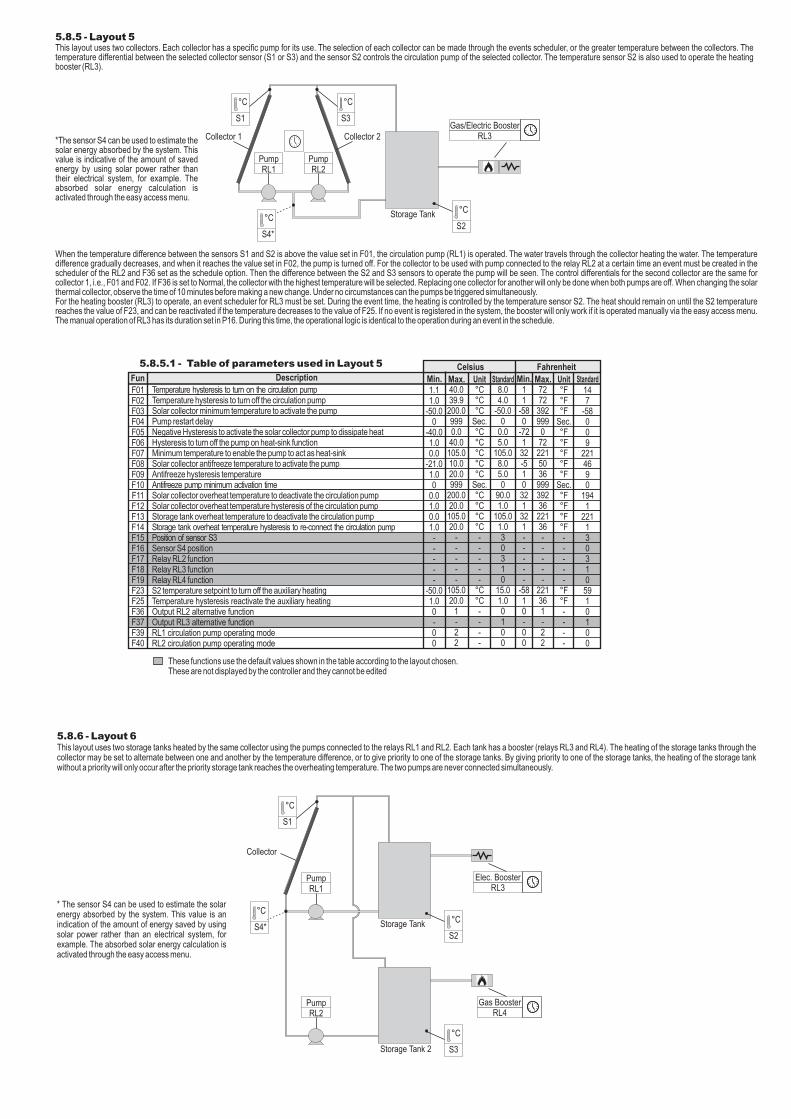
5.8.6 - Layout 6This layout uses two storage tanks heated by the same collector using the pumps connected to the relays RL1 and RL2. Each tank has a booster (relays RL3 and RL4). The heating of the storage tanks through the collector may be set to alternate between one and another by the temperature difference, or to give priority to one of the storage tanks. By giving priority to one of the storage tanks, the heating of the storage tank without a priority will only occur after the priority storage tank reaches the overheating temperature. The two pumps are never connected simultaneously.
Elec. BoosterRL3
Storage Tank °C
S2
Collector
°C
S1
PumpRL1
Gas BoosterRL4
Storage Tank 2
°C
S3
PumpRL2
°C
S4*
* The sensor S4 can be used to estimate the solar energy absorbed by the system. This value is an indication of the amount of energy saved by using solar power rather than an electrical system, for example. The absorbed solar energy calculation is activated through the easy access menu.

The automatic control of pumps is provided by the temperature difference between the collector and each storage tank. The pump connected to the relay RL1 is controlled by the differential sensors S1 and S2. The pump connected to the relay RL2 is controlled by the differential between the sensors S1 and S2.If function F22 is set to give priority to storage tank 1, the pump connected to the relay RL1 will be operated when the differential between the sensors S1 and S2 is equal to or greater than the value set in F01. The water in the solar thermal collector heats the water in storage tank 1. The temperature difference gradually decreases, and when it reaches the value set in F02, the pump is turned off. The differential operation of storage tank 2 will be checked only after the storage tank 1 reaches the value to turn off the pump connected to relay RL1. Therefore the pump connected to relay RL2 will be operated if the temperature differential between sensors S1 & S3 is equal to or less than the value set in F01.If storage tank 1 has the priority in heating, the heating of storage tank 2 will be stopped if the differential between the sensors S1 and S2 is greater than F01. The pump connected to the relay RL2 will then be disconnected and the pump connected to the relay RL1 will be operated.If the function F22 is set to give priority to storage tank 2, the operation will be similar, but giving priority to the operation of the pump connected to relay RL2.If the function F22 is set to alternate the storage tanks, the operation of each pump is set through the F20 and F21 functions. If both pumps are off and the two operational differentials are less than the value set in F01, the pump will be operated in the storage tanks with the lowest temperature. The water will then travel through the collector and the temperature differential will gradually decrease. If the temperature difference between the two storage tanks (sensors S2 and S3) exceeds the value set in F20, the pump will turn off and the pump belonging to the other tank will be operated. The pump has an operating time limit that is set in F21. This is the time when the change of the storage tank to be heated occurs if the temperature difference to turn off the pump (F02) or the temperature difference to alternate the storage tanks (F20) has not been reached.Each storage tank has a heating booster. The heating booster of the storage tank operated by the relay RL3 and the booster of storage tank 2 by relay RL4. Each auxiliary heating output has an independent temperature set-point (F23 and F24). To operate, each auxiliary heating booster must have its operating time set up in the schedule. During the active event the output is operated if the temperature of the storage tank is below the set-point value. If no event is registered in the system, the booster will only work if it is operated manually via the easy access menu. The manual operation of RL3 and RL4 has its duration set in P16 and P17. During this time, the operational logic is identical to the operation during an event in the schedule.
5.8.6.1 - Table of parameters used in Layout 6
40.039.9200.09990.040.0105.010.020.0999
200.020.0105.020.0
-----
50.01440
2105.0200.020.0
---22
727239299907222150369993923622136-----
901440
222139236---22
Temperature hysteresis to turn on the circulation pump Temperature hysteresis to turn off the circulation pump Solar collector minimum temperature to activate the pump Pump restart delay Negative Hysteresis to activate the solar collector pump to dissipate heat Hysteresis to turn off the pump on heat-sink function Minimum temperature to enable the pump to act as heat-sinkSolar collector antifreeze temperature to activate the pumpAntifreeze hysteresis temperature Antifreeze pump minimum activation time Solar collector overheat temperature to deactivate the circulation pump Solar collector overheat temperature hysteresis of the circulation pump Storage tank overheat temperature to deactivate the circulation pump Storage tank overheat temperature hysteresis to re-connect the circulation pump Position of sensor S3Sensor S4 position Relay RL2 functionRelay RL3 functionRelay RL4 functionDifference between S2 and S3 to alternate storage tanks (if S3=tank 2) Maximum time to exchange the storage tank (if F20 does not occur) Operational priority between storage tanksS2 temperature setpoint to turn off the auxiliary heating S3 temperature Setpoint to turn off the auxiliary heatingTemperature hysteresis reactivate the auxiliary heatingOperating mode of booster RL2 and RL3Output RL3 alternative function Output RL4 alternative function RL1 circulation pump operating modeRL2 circulation pump operating mode
11
-580
-72132-510321321-----110
-58-581---00
1.11.0
-50.00
-40.01.00.0
-21.01.00
0.01.00.01.0-----
1.010
-50.0-50.01.0---00
Description Min. Max. Unit Standard Min. Max. Unit Standard
These functions use the default values shown in the table according to the layout chosen.These are not displayed by the controller and they cannot be edited
°C°C°C
Sec.°C°C°C°C°C
Sec.°C°C°C°C-----
°CMin.
-°C°C°C-----
°F°F°F
Sec.°F°F°F°F°F
Sec.°F°F°F°F-----
°FMin.
-°F°F°F-----
147
-58009
2214690
1941
22112041118300
15.015.01.021100
8.04.0
-50.00
0.05.0
105.08.05.00
90.01.0
105.01.02041110300
15.015.01.021100
5.8.7 - Layout 7This layout uses the temperature differential between the sensors S1 and S2 to control the circulation pump through relay RL1. The temperature sensor S2 is used to operate the gas heating booster (RL2). If there is a shortage of gas, the booster connected to relay RL3 will be activated (the lack of gas is identified by the time taken without reaching the set-point). The relay RL4 operates the main water system circulation pump, using the sensor S3 that measures the water temperature at the point of use.
Collector
Pump 1RL1
Storage Tank °C
S2
°C
S1
°C
S3Main water line
RL4
Use outlet point
When the temperature difference between the sensors S1 and S2 is above the value set in F01, the circulation pump (RL1) is operated.The water travels through the solar thermal collector heating the water in the storage tank. The temperature difference gradually decreases, and when it reaches the value set in F02, the pump is turned off.During the time set in the schedule, if the temperature measured by sensor S2 is less than the value set in F23, the relay RL2 is operated as heating until the temperature of S2 reaches the temperature of F23. If the temperature does not reach the set-point within the time set in F26, the relay RL3 is operated as a second booster. When connecting the second booster, the first will be turned off.For this operational logic to work automatically, it is required to set the schedule for relays RL2 and RL3. If the event is set up in only one of the schedulers, only the relay that has the event set up will be operational. If the event is set up only in the RL2 scheduler, it will become operational at the beginning of the event and if the temperature does not reach the set-point value set within the set time in F26, it will be turned off. If the RL3 schedule is set, on its own, the RL3 come into operation only after the time set in F26.
°C
S4*
* The sensor S4 can be used to estimate the solar energy absorbed by the system. This value is an indication of the amount of energy saved by using solar power rather than an electrical system, for example. The absorbed solar energy calculation is activated through the easy access menu.
Elec. BoosterRL3
Gas BoosterRL2

FunCelsius Fahrenheit
F01F02F03F04F05F06F07F08F09F10F11F12F13F14
Temperature hysteresis to turn on the circulation pump Temperature hysteresis to turn off the circulation pump Solar collector minimum temperature to activate the pump Pump restart delay Negative Hysteresis to activate the solar collector pump to dissipate heat Hysteresis to turn off the pump on heat-sink function Minimum temperature to enable the pump to act as heat-sinkSolar collector antifreeze temperature to activate the pumpAntifreeze hysteresis temperature Antifreeze pump minimum activation time Solar collector overheat temperature to deactivate the circulation pump Solar collector overheat temperature hysteresis of the circulation pump Storage tank overheat temperature to deactivate the circulation pump Storage tank overheat temperature hysteresis to re-connect the circulation pump
1.11.0
-50.00
-40.01.00.0
-21.01.00
0.01.00.01.0
40.039.9200.09990.040.0105.010.020.0999
200.020.0105.020.0
°C°C°C
Sec.°C°C°C°C°C
Sec.°C°C°C°C
8.04.0
-50.00
0.05.0
105.08.05.00
90.01.0
105.01.0
11
-580
-72132-510321321
727239299907222150369993923622136
°F°F°F
Sec.°F°F°F°F°F
Sec.°F°F°F°F
147
-58009
2214690
1941
2211
5.8.7.1 - Table of parameters used in Layout 7
The booster heaters can also be operated through the easy access menu. In this case, the operation will be identical to the operation when set in the event scheduler. The duration of the manual operation of each relay is set in P15 and P16.At the set time, the relay RL4 will operate the circulation of water in the main water line. The sensor S3 measures the outlet temperature at the point of use. If the temperature sensor S3 is less than the value of F31, the relay RL4 will operate until it reaches this temperature. In function F32 the temperature difference of sensor S3 is set; this should decrease to operate the RL4 pump. The relay will remain on until it reaches the set-point if it has not passed the minimum time set in function F33. In the function F34 the maximum time that relay RL4 is operational is set. After this time, the output is turned off, even if the set-point is not reached. After switching off, the relay RL4 is only reconnected after the time set in F35.
Description Min. Max. Unit Standard Min. Max. Unit Standard
F15F16F17F18F19 F23F25F26F30F31F32F33F34F35F36F37F38F39
Position of sensor S3Sensor S4 position Relay RL2 functionRelay RL3 functionRelay RL4 functionS2 temperature setpoint to turn off the auxiliary heating Temperature hysteresis reactivate the auxiliary heatingTime to reach Setpoint (F23 or F24) before turning on 2nd boosterOperating mode of booster RL2 and RL3Setpoint to activate the circulation of water in the Main water lineHysteresis for disabling the water circulation in the Main water lineMinimum time of the water circulation in the Main water lineMaximum time of the water circulation in the Main water lineMinimum time between operations involving water circulation in the Main water line Output RL2 alternative function Output RL3 alternative function Output RL4 alternative function RL1 circulation pump operating mode
-----
-50.01.01-
-50.01.0111
0
---
-----
105.020.01440
-200.020.0144014401440
2
---
-----
°C°C
Min.-
°C°C
Min.Min.Min.
----
40112
15.01.0300
25.01.0106051110
-----
-5811-
-581111
0
---
-----
22136
1440-
39236
144014401440
2
---
-----
°F°F
Min.-
°F°F
Min.Min.Min.
----
40112591300771106051110
These functions use the default values shown in the table according to the layout chosen.These are not displayed by the controller and they cannot be edited
5.8.8 - Layout 8This layout uses the temperature differential between the sensors S1 and S2 to control the circulation pump through relay RL1. The temperature sensor S2 is used to operate the heating booster connected to relay RL2 and the heat sink in the relay RL3. The relay RL4 operates the main water system circulation pump, using the sensor S3 that measures the water temperature at the point of use.
RL3Collector
Pump 1RL1
Storage Tank
°C
S2
°C
S1
°C
S3Main water lineRL4
When the temperature difference between the sensors S1 and S2 is above the value set in F01, the circulation pump (RL1) will be operated.The water travels through the collector heating the water in the tank. The temperature difference gradually decreases, and when it reaches the value set in F02, the pump is turned off.During the time set in the schedule, if the temperature measured by sensor S2 is less than the value set in F23, the relay RL2 is operated as heating until the S3 temperature reaches the temperature of F23.The boosters can also be operated through the easy access menu. In this case, the operation will be identical to the operation when set in the event scheduler . The easy access menu also allows the manual disconnection of the booster, which is operated by the schedule or triggered manually. When turning off the booster as an active event, it will remain off until triggered again by the next event or manually activated. To manually reconnect the booster that still has an active event, it will remain active until the end of the event and not the time set in parameter P15.During the time set in the schedule, the relay RL4 triggers the movement of water in the main water line. The sensor S3 measures the outlet temperature at the point of use. If the temperature sensor S3 is less than the value of F31, the pump connected to relay RL4 will operate until it reaches this temperature. In function F32 the temperature difference of sensor S3 is set, this should decrease to operate the RL4 pump. The pump will remain on when it reaches the set-point if it has not passed the minimum time set in function F33. In the function F34 the maximum time that relay RL4 is operational is set After this time, the output is turned off, even if the set-point is not reached. After switching off, the relay RL4 is only reconnected after the time set in F35.
°C
S4*
Use outlet point
*The sensor S4 can be used to estimate the solar energy absorbed by the system. This value is an indication of the amount of energy saved by using solar power rather than an electrical system, for example. The calculation of absorbed solar energy is activated through the easy access menu.
Gas / RL2
Elec. Booster

These functions use the default values shown in the table according to the layout chosen.These are not displayed by the controller and they cannot be edited
F27F29F31F32F33F34F35F36F37F38F39
S2 temperature setpoint to activate the heat sink Temperature hysteresis to stop auxiliary heating Setpoint to activate the circulation of water in the Main water lineHysteresis for disabling the water circulation in the Main water lineMinimum time of the water circulation in the Main water lineMaximum time of the water circulation in the Main water lineMinimum time between operations involving water circulation in the Main water line Output RL2 alternative function Output RL3 alternative function Output RL4 alternative function RL1 circulation pump operating mode
-50.01.0
-50.01.0111---0
105.020.0200.020.0144014401440-
---2
°C°C°C°C
Min.Min.Min.
----
45.01.025.01.0110101010
-581
-581111---0
2213639236
144014401440
---2
°F°F°F°F
Min.Min.Min.
----
1131771110101010
5.8.8.1 - Table of parameters used in Layout 8
FunCelsius Fahrenheit
F01F02F03F04F05F06F07F08F09F10F11F12F13F14
1.11.0
-50.00
-40.01.00.0
-21.01.00
0.01.00.01.0
40.039.9200.09990.040.0105.010.020.0999
200.020.0105.020.0
°C°C°C
Sec.°C°C°C°C°C
Sec.°C°C°C°C
11
-580
-72132-510321321
727239299907222150369993923622136
°F°F°F
Sec.°F°F°F°F°F
Sec.°F°F°F°F
F15F16F17F18F19F23F25
-----
-50.01.0
-----
105.020.0
-
---
°C°C
-----
-581
-----
22136
-----
°F°F
Temperature hysteresis to turn on the circulation pump Temperature hysteresis to turn off the circulation pump Solar collector minimum temperature to activate the pump Pump restart delay Negative Hysteresis to activate the solar collector pump to dissipate heat Hysteresis to turn off the pump on heat-sink function Minimum temperature to enable the pump to act as heat-sinkSolar collector antifreeze temperature to activate the pumpAntifreeze hysteresis temperature Antifreeze pump minimum activation time Solar collector overheat temperature to deactivate the circulation pump Solar collector overheat temperature hysteresis of the circulation pump Storage tank overheat temperature to deactivate the circulation pump Storage tank overheat temperature hysteresis to re-connect the circulation pump Position of sensor S3Sensor S4 position Relay RL2 functionRelay RL3 functionRelay RL4 functionS2 temperature setpoint to turn off the auxiliary heating Temperature hysteresis reactivate the auxiliary heating
Min. Max. Unit Standard Min. Max. Unit StandardDescription
147
-58009
221
01941
221140122591
469
8.04.0
-50.00
0.05.0
105.08.05.00
90.01.0
105.01.040122
15.01.0
5.8.9 - Layout 9This layout uses two solar thermal collectors. Each collector has a specific pump for its use. The selection of each collector can be made through the events scheduler, or the greater temperature between the collectors. The temperature differential between the selected collector sensor (S1 or S3) and the sensor S2 controls the circulation pump of the selected collector. The temperature sensor S2 is used to operate the heating booster connected to relay RL3. The relay RL4 operates the main water system circulation pump, using the sensor S3 that measures the water temperature at the point of use.
When the temperature difference between the sensors of the PCB S1 and S2 is above the value set in F01, the circulation pump (RL1) is operated. The water travels through the collector heating the water in the tank. The temperature difference gradually decreases, and when it reaches the value set in F02, the pump is turned off. For the collector to be used with pump connected to the relay RL2 at a certain time, an event must be created in the scheduler of the RL2 and F36 set as the scheduling option. Then the difference between the S2 and S3 sensors to operate the pump will be seen. The differential control for the pump connected to RL2 are the same as the pump connected to RL1, i.e., F01 and F02. If F36 is set to Normal, the collector with the highest temperature will be selected. Replacing one collector for another will only be done when both pumps are off. When changing the solar thermal collector, observe the time of 10 minutes before making a new change. Under no circumstances can the pumps be triggered simultaneously.For the heating booster (RL3) to operate, an event Schedule for RL3 must be set. During the event time, the heating is controlled by the temperature sensor S2. The heating remains on until the temperature in S2 reaches the value set in F23. If no event is registered in the system, the booster willonly work if it is operated manually via the easy access menu. The manual operation of RL3 has its duration set in P16. During this time, the operational logic is identical to the operation during an event in the schedule.The relay RL4 will operate the circulation of water in the main water line. The operating time of the event schedule relay RL4 must be set. During the active event, the S4 sensor measures the outlet temperature of the water at the point of use. If the temperature sensor S3 is less than the value of F31, the pump connected to relay RL4 will operate until it reaches this temperature. In function F32 the temperature difference of sensor S3 is set, this should decrease to operate the RL4 pump. The pump will remain on when it reaches the set-point if it has not passed the minimum time set in function F33. In the function F34 the maximum time that relay RL4 is operational is set After this time, the output is turned off, even if the set-point is not reached. After switching off, the relay RL4 will only be reconnected after the time set in F35.If no event is registered in the schedule of relay RL4, the circulation pump of the main water line will only work if it is triggered manually via the for access menu. The manual operation of RL4 has its duration set in P17. During this time, the operational logic is identical to the operation during an event in the schedule.
°C
S4Main water lineRL4
Gas/Electric BoosterRL3
Collector 1
Storage Tank °C
S2
°C
S3
Collector 2
°C
S1
PumpRL2
PumpRL1
Use outlet point
FunCelsius Fahrenheit
F01F02F03F04F05F06F07F08F09F10F11
Temperature hysteresis to turn on the circulation pump Temperature hysteresis to turn off the circulation pump Solar collector minimum temperature to activate the pump Pump restart delay Negative Hysteresis to activate the solar collector pump to dissipate heat Hysteresis to turn off the pump on heat-sink function Minimum temperature to enable the pump to act as heat-sinkSolar collector antifreeze temperature to activate the pumpAntifreeze hysteresis temperature Antifreeze pump minimum activation time Solar collector overheat temperature to deactivate the circulation pump
1.11.0
-50.00
-40.01.00.0
-21.01.00
0.0
40.039.9200.09990.040.0105.010.020.0999
200.0
°C°C°C
Sec.°C°C°C°C°C
Sec.°C
8.04.0
-50.00
0.05.0
105.08.05.00
90.0
11
-580
-72132-51032
72723929990722215036999392
°F°F°F
Sec.°F°F°F°F°F
Sec.°F
147
-58009
2214690
194
5.8.9.1 - Table of parameters used in Layout 9
Description Min. Max. Unit Standard Min. Max. Unit Standard

These functions use the default values shown in the table according to the layout chosen.These are not displayed by the controller and they cannot be edited
F12F13F14F15F16F17F18F19F23F25F31F32F33F34F35F36F37F38F39F40
Solar collector overheat temperature hysteresis of the circulation pump Storage tank overheat temperature to deactivate the circulation pump Storage tank overheat temperature hysteresis to re-connect the circulation pump Position of sensor S3Sensor S4 position Relay RL2 functionRelay RL3 functionRelay RL4 functionS2 temperature setpoint to turn off the auxiliary heating Temperature hysteresis reactivate the auxiliary heatingSetpoint to activate the circulation of water in the Main water lineHysteresis for disabling the water circulation in the Main water lineMinimum time of the water circulation in the Main water lineMaximum time of the water circulation in the Main water lineMinimum time between operations involving water circulation in the Main water line Output RL2 alternative function Output RL3 alternative function Output RL4 alternative function RL1 circulation pump operating modeRL2 circulation pump operating mode
1.00.01.0-----
-50.01.0
-50.01.00000--00
20.0105.020.0
-----
105.020.0200.020.0144014401440
3--22
°C°C°C-----
°C°C°C°C
Min.Min.Min.
-----
1321-----
-581
-5810000--00
3622136-----
2213639236
144014401440
3--22
°F°F°F-----
°F°F°F°F
Min.Min.Min.
-----
1.0105.01.032312
15.01.025.01.01101001100
12211323125917711101001100
5.8.10 - Customized Layout (custom)All layouts shown in this manual are intended to facilitate the setting of EnergySol plus, and it pre-configures some functions and does not show the functions that are not relevant to the application of such a layout. However, the user can choose to create their own topology freely using all the functions available with this controller. For this reason, when setting up the layout one should select the "Custom" option.
6 - EASY ACCESS FUNCTIONSIn the easy access menu, one can set the overheating temperature of the storage tanks, booster setpoints, operation of the pump and control of the power meter. To access this menu, press the
key while in the main EnergySol screen. To access any of the functions and confirm its value,
simply press the key.
To exit the function without changing its value or exit the menu, simply press the key.The configurable functions of the easy access menu are as follows:
Menu
OK
Menu
01-S2 Overheatng
02-S2 SetP Ht
04-S3 SetP Ht
05-S3 SetP Diss
03-S2 SetP Diss
06-Recirc SetP
07-RL2 Activat
- (F13)
- (F23)
- (F27)
- (F24)
- (F28)
- (F31)
- Manual Operation RL2
- Manual Operation RL3
- Manual Operation RL4
- Operational Mode of pump RL1
- Operational Mode of pump RL2
- Operation of the power meter
- Restarts energy metering
08-RL3 Activat
09-RL4 Activat
10-RL1 Op Mode
11-RL2 Op Mode
12-Energy Meter
13-Reset Energy
The functions are displayed only if its operation is set. For example, the set-point for temperature S2 for the auxiliary heating will only be displayed if the function RL2 is set as an auxiliary heating (layouts 5, 6, 7, 8 and 9). The functions that are always displayed are overheating of the storage tank and mode of operation of the pump RL1.
8.4 - Differential Control
8.5 - Energy MeterIf the sensor 4 is used at the input of the solar thermal collector, the EnergySol plus enables the estimation function of the solar energy collected. The estimation of energy is performed based on the flow of the pump used and the temperature variation of the water passing through the collector. For the measurement to be carried out correctly, it is necessary that the parameters P18, P19 and P20 are configured according to the installation.The density (P18) and the specific heat (P19) refer to the liquid heated by the collector. The default values used are for water: density 997kg / m³ and specific heat 4180 J/(kg K).If an additive is used, such as Ethylene glycol, the values supplied by the manufacturer should be used.
8.2 - Status of relay outputs
$ - Output off; % - Output on;$& - Output for manual override off;%& - Output for manual override off.
$ - Output off (Active event) % - Output on (Active event)
8.3 - Reading the Sensors
8 - INDICATIONS
By repeatedly pressing the one can see more information about EnergySol plus.The selected view will remain on display for 10 seconds and then the screen returns to the main screen. The possible options are:
8.1 - Clock
7 - CHANGING THE TEMPERATURE UNITSPara alterar a unidade de temperatura, acesse os menu 01-Codigo de acesso , enter the 231 code and confirm. Then the temperature unit selection screen will be shown indicating the current unit of measurement.
Press and use the and to change the unit of measurement. Press again to confirm.OK
E
E
Temperature unitCelsius
Friday17:00
RL1 RL2 RL3 RL4% $ $ %&
$S1-S2: 10.0#%S1-S3: 15.0#
Sensor 150.0#
S1:50.0 S2:26.0S3:50.0 S4:----
Energy Meter 500.00kWh

11 - INTRUMENT FIXATION MODE
11.1 - Screw fixation (WALL-MOUNTED)
10 - ALARM AND ERROR INDICATIONSIn the event of alarm or error in reading the sensors, EnergySol plus displays a warning message on the display with the backlight blinking.
Freeze Alarm
Hi Temp: S1
Erro:S1 S2 S3 S4
9 - MINIMUM AND MAXIMUM
By pressing the key repeatedly one can view the instructions for the minimum and maximum temperature for each sensor.The selected view will remain on the display for 10 seconds and then the screen will return to the
main screen. To delete the records of each sensor, press the key for 2 seconds during its presentation.
Sensor 1 10.0# 27.0#
If the schedule is off for a long time, the clock may lose its settings due to the low internal battery level that keeps it in operation. In this case the "set clock" message will be displayed. To fully recharge the battery, the controller needs to be energized for around 10 hours.
Adjust Clock
A AB B
A B
12 - INTEGRATING CONTROLLERS, RS-485 SERIAL INTERFACE
AND COMPUTER
®
EnergySol plus
A B
Full GaugeControls
Full GaugeControls
Terminationresistor (120R)
Connecting Block for Serial CommunicationUsed to connect more than one instrument to the Interface. The wire's connections must be made in agreement with the following rules: terminal A of the instrument connects to the terminal A of the
, that must be connected with the terminal A of the Interface. Repeat the action for terminal
Connecting block
B.A third terminal is provided to use in installations that need to connect the cable shield to ground.
RS-485 Network Serial interface RS-485
Full Gauge
RS-485 Serial Interface
®
Device used to establish the connection Full Gauge Controls’ instruments with the Sitrad .
IMPORTANTAccording to the chapters from the IEC60364 standard: 1: Install protectors against over voltage on power supply2: Sensor cables and computer signals can be together, however not at the same place where power supply and load wires pass for3: Install suppresor of transient in parallel to loads to increase the usefull life of the relays
Contact suppressor connection diagram
Sup
pres
sor
A1
A2
A1 e A2 are thecontactor coils.
ENVIRONMENTAL INFORMATIONPackage:The packages material are 100% recyclable. Just dispose it through specialized recyclers.
Products:The electro components of Full Gauge controllers can be recycled or reused if it is disassembled for specialized companies.
Disposal:Do not burn or throw in domestic garbage the controllers which have reached the end-of-life. Observe the respectively law in your region concerning the environmental responsible manner of dispose its devices. In case of any doubts, contact Full Gauge controls for assistance.


![MT530ES05-02T-15226 -FORMATO PARA INTERNET...Para entrar no menu de ajuste dos setpoints pressione / por 2 segundos. Será exibida a mensagem [SP1,]no display, em seguida exibirá](https://img.dokumen.tips/doc/110x75/5fdefe5a0a7d517ba00acac9/mt530es05-02t-15226-formato-para-internet-para-entrar-no-menu-de-ajuste-dos.jpg)