Embed Size (px)
Citation preview

Hybrid and electric vehicles, energy storage technologies and control systems
National and international R&D-projects, research institutions and funding programs
Vienna, October 21st 2008 in cooperation with and
Energy Storage Systems for Hybrid Vehicles; from Racing to Production Cars
Georg Brasseur, Graz University of Technology

2Rethinking Propulsion.
OutlineHybrid Endurance Racing in 2008 and 2009Hybrid System Design Features for Racing CarsEnergy and Power Storage for Racing Cars and Series-Production VehiclesHydraulic Energy StorageFlywheel Energy Storage Electric Energy Storage with Super Capacitors or BatteriesLessons Learned for Energy Storage Systems used at Racing Cars
Formula 1 Key Specifications for a Kinetic Energy Recovery SystemLessons Learned for Energy Storage Systems used at Hybrid Production Cars Work at the Institute in the Field of Batteries

3Rethinking Propulsion.
from: http://www.motorsport-total.com/mehr/news/2008/05/Was_steckt_hinter_dem_Hybrid-Apollo_08052407.html
Battery Compartment
Hybrid System
Gumpert Apollo at the 24h Nürburgring Race in May 2008
90 Li-ion cells with 27 Ah from GAIA
Courtesy of Gumpert Sportwagenmanufaktur
Hybrid Endurance Racing in 2008
Exploded View

4Rethinking Propulsion.
Hybrid Endurance Racing in 2009
Courtesy of Peugeot Motorsport
Power Electronic Converter
60kW Gear-Driven Electric Motor-
Generator
10 Li-Ion Battery Modules with 60 Cells each 60 kW (80 hp) for 20 s per lap
“Push-to-Pass”
Peugeot 908 Hybridfor Endurance Racing

5Rethinking Propulsion.
Hybrid System Design Features for Racing Cars
Powerful boosting (discharging) and strong recuperative breaking (charging), permanent hybrid system availability,small and lightweight components with a low centerof gravity,high system efficiency to prevent excessive coolingdemand (weight and space increase) andlimited product life (e.g. a few races or one season).
Specific requirements for a rechargeable energy storageHigh peak power rating (40 to 100 kW)but low storable energy (0.1 to 2 kWh):
e.g. 60 kW output power for 8 sec: equals 480 kWs = 133 Wh (Starter battery: 45 Ah @ 12 V = 540 Wh).

6Rethinking Propulsion.
Energy and Power Storage for RacingCars and Series-Production Vehicles40 to 100 kW, 0.1 to 2 kWh and weight as low as possible
Hydraulic,Flywheel,Electric with Super or Ultra Capacitors andElectric with rechargeable batteries
36 s0.1 h 3.6 s
Nano-Titanate
Nano-Titanate: Data from Altairnano NanoSafe™ Battery Technology
Flywheel systems and hydraulic accumulators can operate anywhere in the green box with almost infinite life.
Operating area of a storage for racing cars.
The hydraulic hybrid truck on the next slide operates here.

7Rethinking Propulsion.
Hydraulic Energy StoragePros:
High efficiency- Hydraulic Hybrids > 70 % - Electric Hybrids < 25 %
Cons:Weight and sizeControllabilityCommun. with the engine ECU
From www.epa.gov/otaq/technology, Clean Automotive Technology
Efficiencies While Accelerating &Breaking

8Rethinking Propulsion.
Flywheel Energy Storage ITwo solutions for a flywheel energy storage:The flywheel is operated in a vacuum containment ate.g. 50,000 rpm
a) Mechanical solution: Mechanically propelled flywheel is coupled to a Continuous Variable Transmission (CVT) that is hydraulically actuated and electrically controlled. Roundtrip efficiency including CVT > 70 %
b) Electromechanical solution: Fast spinning rotors of two or four reluctance motors. The rotors serve as flywheels and store energy in the inertia of fast spinning armatures (like with the mechanical solution). Charging and discharging as well as the conversion of the “mechanical rotor energy” to electric energy is done by magnetic fields originating from the stator windings. Roundtrip storage efficiency > 90 %
a)
b)
Photo of a mechanically propelled flywheel withCVT from supplier a)
Photo of an electromechanicalflywheel storage from supplier b)

9Rethinking Propulsion.
Pros:High efficiency: > 90 %Flywheel plus CVT > 70 %.Low weight and compact design.Operating temperature up to around 100 °C (small radiator volume).
Cons:Dynamic reaction forces (Coriolis Force) introduced to the moving vehicle due to a fast spinning flywheel.- Possible solution: two or four flywheels (rotors of electric motors)spinning clockwise and counterclockwise respectively.
Flywheel safety:- Debris of a bursting flywheel must be captured within the flywheel
containment and - return of the flywheel to rest in case of emergency, e.g. an accident,within a few seconds.
Dynamic controllability of the mechanical solution.
Flywheel Energy Storage II

10Rethinking Propulsion.
Electric Energy Storage withSuper Capacitors or Batteries
Courtesy of Peugeot MotorsportRagone plot illustrating the energy-power characteristics of various energy storages
Data from a Ragone Plot is somehow miss leading: Thermal power losses of the storage device are not visible!Internal (dynamic) storage resistance is the crucial specification
Examples for a 50 % duty cycle @ 60 kW (400 V & 150 A) with Lithium Batteries and with Super Capacitors:

11Rethinking Propulsion.
Lessons Learned for EnergyStorage Systems
used at Racing Cars
Hybrid racing cars with permanent recuperation & boost supportBatteries should not be used beyond 20 kW• if the weight of the storage has to be as low as possible and• if a battery surface temperature of less than 40 °C can not
be secured.Hydraulic storage system benefit from high roundtrip efficiencyand small radiator surfaces (> 100°C) but suffer from a huge size. UltraCap benefit from high efficiency but the surface temperature must be kept below around 50 °C.Mechanical and electromechanical flywheel storage benefit from high efficiency and small radiator surfaces (> 100°C). If safety is secured: best solution for racing cars.
Hybrid racing cars with “push-to-pass” buttonThe driver can get a boost from the hybrid system only once per lap. The low average charge and discharge power allows all 4 types of storages. Introduced to the 2009 Formula 1 rules.

12Rethinking Propulsion.
Formula 1 Key Specifications for aKINETIC ENERGY RECOVERY SYSTEM (K. E. R. S.)
Why? Better lap times and/or better fuel efficiency
… “1.20 Kinetic Energy Recovery System (KERS): a system that is designed to recover kinetic energy from the car during braking, store that energy and make it available to propel the car”…
… ”5.2.3 The maximum power, in or out, of any KERS must not exceed 60 kW”.
Energy released from the KERS may not exceed 400 kJ in any one lap.
“Measurements will be taken at the connection to the rear wheel drive train.”…
The challenge is: To overcompensate the added vehicle weight and the vehicle’s higher center of gravity.
13Rethinking Propulsion.
Lessons Learned for EnergyStorage Systems
used at Hybrid Production Cars
Hybrid production vehicles (HVs) with permanent recuperation & boost support
Low price, safety and longevity are the key features of the storage.• Battery temperature and depth-of-discharge (DOD) define the
maximum power level of the hybrid boost and recuperation. • Today’s HVs use only 5 % DOD in 95 % of all boosts 50 to
150 Wh(!) almost like in your Laptop battery. In the near future UltraCaps could be an issue for sporty HVs.All other storage types are too expensive, too bulky, suffer from too much wear or may be unsafe.Frequently used powerful boost and recuperation is not a problemfor a high capacity on-board battery (>20 kWh) Plug-in Hybrid Electric Vehicle (PEV)
14Rethinking Propulsion.
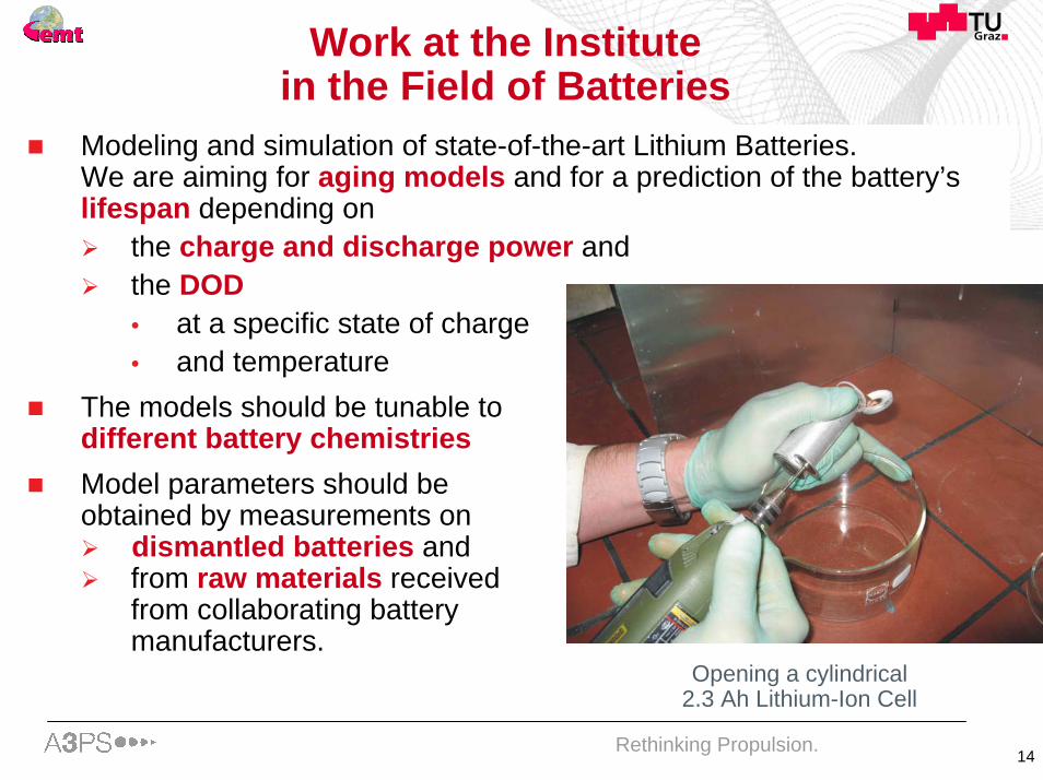
Work at the Institute in the Field of Batteries
Modeling and simulation of state-of-the-art Lithium Batteries. We are aiming for aging models and for a prediction of the battery’s lifespan depending on
the charge and discharge power and the DOD• at a specific state of charge• and temperature
The models should be tunable to different battery chemistriesModel parameters should beobtained by measurements on
dismantled batteries and from raw materials received from collaborating battery manufacturers.
Opening a cylindrical 2.3 Ah Lithium-Ion Cell

15Rethinking Propulsion.
Work at the Institute in the Field of Batteries
Cylindrical 2.3 AhLithium-Ion cell withremoved metal can
Anode, cathode andseparator of a 2.3 Ah
Lithium-Ion cell
Cycling of a 1 AhLithium-Ion cell at three temperature levels

16Rethinking Propulsion.
Work at the Institute in the Field of Batteries
Cycling of a 1 AhLithium-Ion cell at three temperature levels
Graphite surface of anewly dismantled cell
Graphite surface of a cellafter 300 cycles @ 60°C
Graphite Fluorine Carbon Oxygen Element distribution on a 37,852 µm cutout of the anode’s surface
Cell cycling and measuring the iron concentration of the anode’s surface

17Rethinking Propulsion.
contact
Univ.-Prof. Dr. Georg BrasseurDepartment of Electrical Measurement and MeasurementSignal Processing, Graz University of Technology
address: TU Graz, Inst. E 438Kopernikusgasse 24-IVA-8010 Graz, Austria
tel: +43-316-873-7271fax: +43-316-873-7266web: www.emt.tu-graz.ac.atemail: [email protected]

18Rethinking Propulsion.
Thank you for your attention !!!!!


